ASTER Technology IDCAM-447EW ID/IPCAM User Manual NVR IPCAM manual
Shenzhen ASTER Technology Co., Limited ID/IPCAM NVR IPCAM manual
User Manual

NVR&IPCAM USER MANUAL V1.0
N
NV
VR
R&
&I
IP
PC
CA
AM
M
(USER MANUAL)
V1.0
Thanks for choosing our products, please read this manual carefully before use!

NVR&IPCAM USER MANUAL V1.0
NOTICE
Installation condition
1) In order to ensure your rights, please read this manual carefully before installation.
2) This machine is indoor equipment. In order to prevent a short circuit or shock hazard, do not place it
in rain or wet environment.
3) If there is any solid or liquid in the machine, please disconnect the power at once, and ask the
qualified technicians to check before restart.
4) It cannot be installed in excessive dust or mechanical vibration place. It cannot be installed near any
heat sources such as radiators, air duct. Please put it in air circulation place.
5) It is a precision machine; almost no part can be repaired by user. Do not disassemble this product.
Failure must be repaired by qualified technicians.
6) Please disconnect the power before connecting with other devices.
7) Please turn off and pull out the pug, If the machine is not be used for a long time,
8) Do not use the power which could not match the power adapter.
9) In project installation, connect the ground to avoid lightning damage to the main chip. If the monitor
must be grounded, please avoid leakage damage to the machine.
10) Please select high quality hard disk which could meet the working demand of NVR. Please purchase
hard disk from regular merchants.
Installation Instructions
1) The Manual is for reference only.
2) The products are updated without extra notice.
3) Please contact our customer service department for the latest procedures and additional documentation.
4) Description of doubt or dispute subject to the final interpretation of our company.

NVR&IPCAM USER MANUAL V1.0
Table of contents
1 Preparation....................................................................................................................................................... 4
1.1 The topology ..................................................................................................................................... 4
1.2 IPCAM&NVR connection settings ................................................................................................. 4
1.3 Corresponds to the version of IPCAM&NVR ............................................................................... 7
1.4 Interface ............................................................................................................................................ 8
1.4.1 IPCAM interface ...................................................................................................................... 8
1.4.2 NVR front panel and interface ............................................................................................... 8
1.5 Remote controller ........................................................................................................................... 11
1.6 Mouse .............................................................................................................................................. 12
1.7 Live view ......................................................................................................................................... 13
1.7.1 Live mode icons ...................................................................................................................... 13
1.7.2 Mouse tools ............................................................................................................................. 13
2 Operations ................................................................................................................................................... 14
2.1 Turn on the NVR ............................................................................................................................ 14
2.2 System setup ................................................................................................................................... 15
2.3 Camera setup and area mark setup ............................................................................................. 16
2.3.1 Change the camera name ...................................................................................................... 16
2.3.2 Area mark setup ..................................................................................................................... 16
2.4 Alarm setup .................................................................................................................................... 17
2.5 Record operation ........................................................................................................................... 20
2.5.1 Preparation for recording ..................................................................................................... 20
2.5.2 Recording start and stop ....................................................................................................... 20
2.6 Playback.......................................................................................................................................... 21
2.7 Backup ............................................................................................................................................ 22
2.8 Audio setup ..................................................................................................................................... 23
2.9 PTZ setup ....................................................................................................................................... 23
2.10 User setup ....................................................................................................................................... 25
2.11 User shift ......................................................................................................................................... 26
2.12 Night view setup ............................................................................................................................. 26
2.13 Turn off the NVR ........................................................................................................................... 26
2.14 The status of HDD ......................................................................................................................... 27
2.15 IE connection .................................................................................................................................. 27
2.16 NVR networking example ............................................................................................................. 30
NVR&IPCAM USER MANUAL V1.0
4
1 Preparation
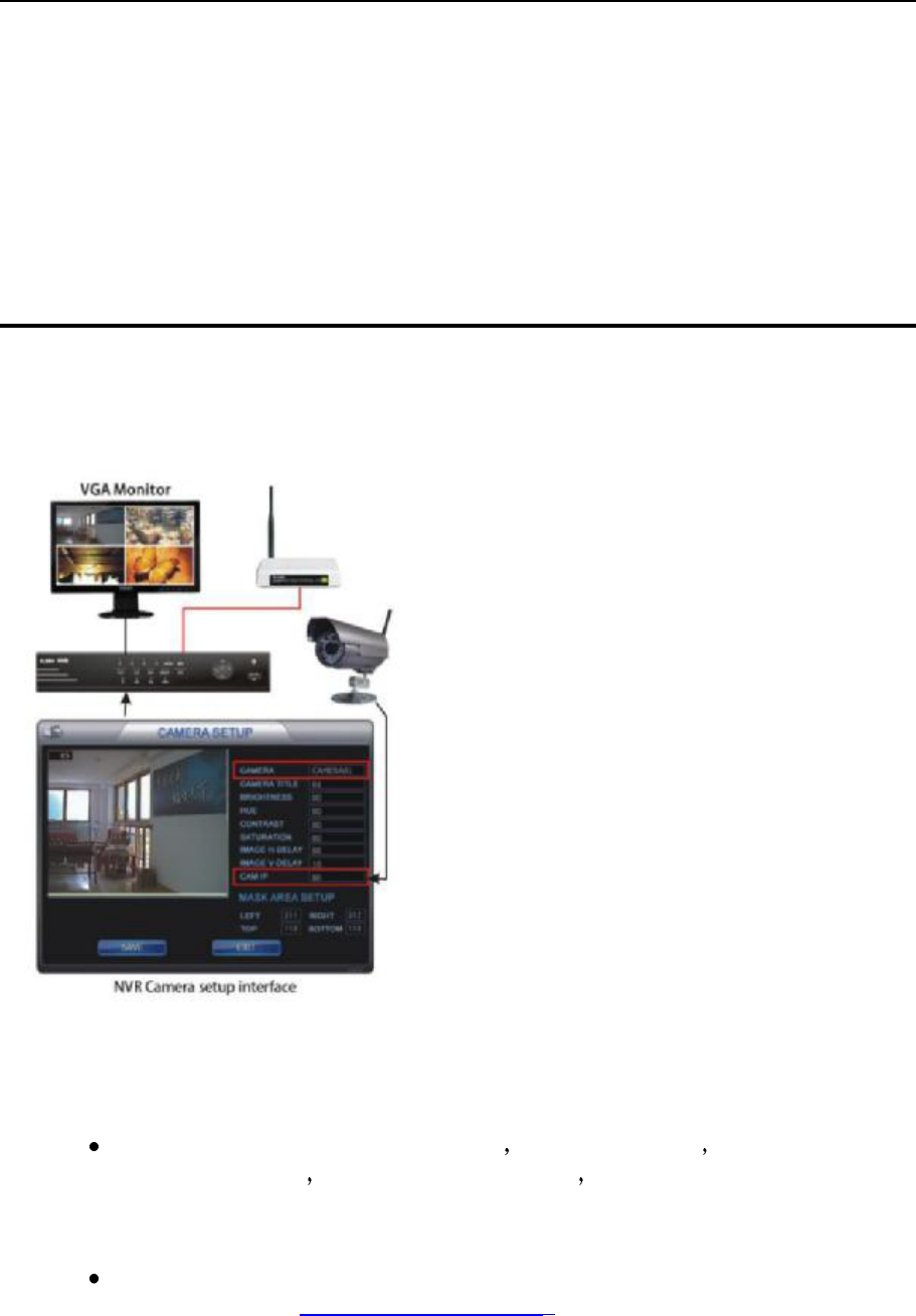
1.1 The topology
1.2 IPCAM&NVR connection settings
IPCAM connected to PC via net cable PC set to a fixed IP PC IP could be set
as192.168.1.101 subnet mask 255.255.255.0 default gateway 192.168.1.1.
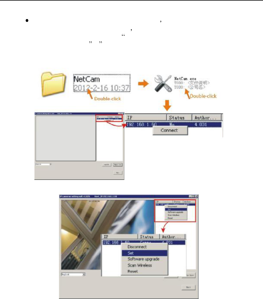
Copy Netcam.exe application in the CD from PC to USB disk. I t also could be
download from http://www.fab111.com:83. Then run it.
NVR&IPCAM USER MANUAL V1.0
5
Press reset button and power on the IPCAM NetCam software will show the IP:
192.168.1.60 thirty seconds later and then release the button. Move the cursor to
the IP and right click it, click connect", it will pop up the image; then right click
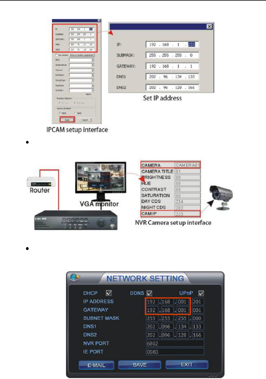
the IP and select set to set the IP. IPCAM will restart if the IP changed. If the
network segment of the IPCAM and PC is the same, you could see the new IP 30
seconds later. If the network segments are different, it could not be connected.
You will see the below picture after connection.
NVR&IPCAM USER MANUAL V1.0
6
The IP of IPCAM could be set in Camera setting menu in NVR.
Log in Network setting menu of NVR via network remote client to check the IP of
NVR and IPCAM in the same network segment.
NVR&IPCAM USER MANUAL V1.0
7
When setting alarm information, the network segment of Router, IPCAM and
NVR must be the same. NVR and Netcam software could not be connected to
IPCAM at the same time.
1.3 Corresponds to the version of IPCAM&NVR
Steps
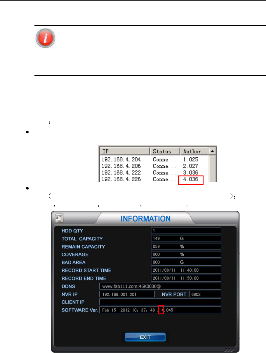
Open NetCam software in PC, when you see the IP, you could see the version of
IPCAM.
If the version of IPCAM is 4.036, then the version of NVR should be begin with 4.
Press INFO key in NVR front panel, it will pop up the INFO menu. 1.*** is
D1 2.*** is 960H 3.*** is 720P 4.*** is 1080P
NVR&IPCAM USER MANUAL V1.0
8
1.4 Interface
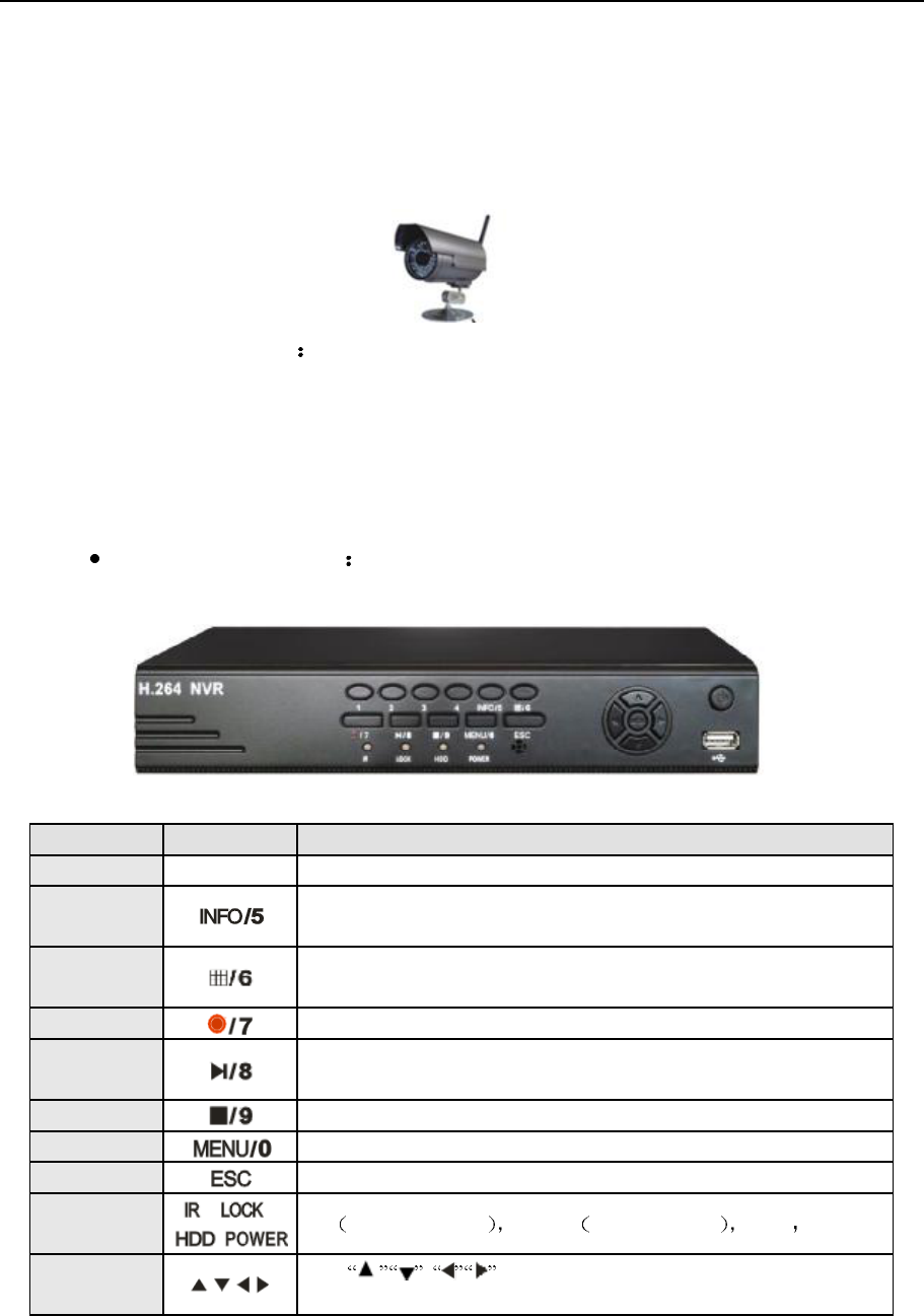
1.4.1 IPCAM interface
Full version interface
1) Power interface, 12V 1.5A.
1.4.2 NVR front panel and interface
A. Front panel
name icon Function
NO. keys 0-4 Switch channels; input password.
INFO/5 Press
it to popup information menu; press it again to enter into Log list;
input password.
16Split
screen/6
Press it to enter into four split screen, press it again to nine split screen;
input password.
Record/7
Record; input password
Play/8 Press it t
o pop up search menu, select the file to play; press it in play
mode to pause; input password.
Stop/9
Stop play or record; input password.
Menu/0
Menu; exit from sub-menu; input password.
Exit
Exit; press it in live mode to hide the mouse icons.
Mode light
IR remote controller LOCK front panel lock HDD POWER
Direction and
confirm a)
direction keys; control the direction of PTZ;
press left/ right key to play fast forward/ rewind in play mode;
NVR&IPCAM USER MANUAL V1.0
9
b) confirm.
c) press left/ rig
ht key to play fast forward/ rewind in play
mode;
d)
switch cameras in play and live mode. The cameras after
four should be switched via these two keys.
USB2.0 Connect to USB device to upgrade, backup; connect to USB mouse.
Power Power on/off
IR receiver
Receive the signal of remote controller. It could not be covered.
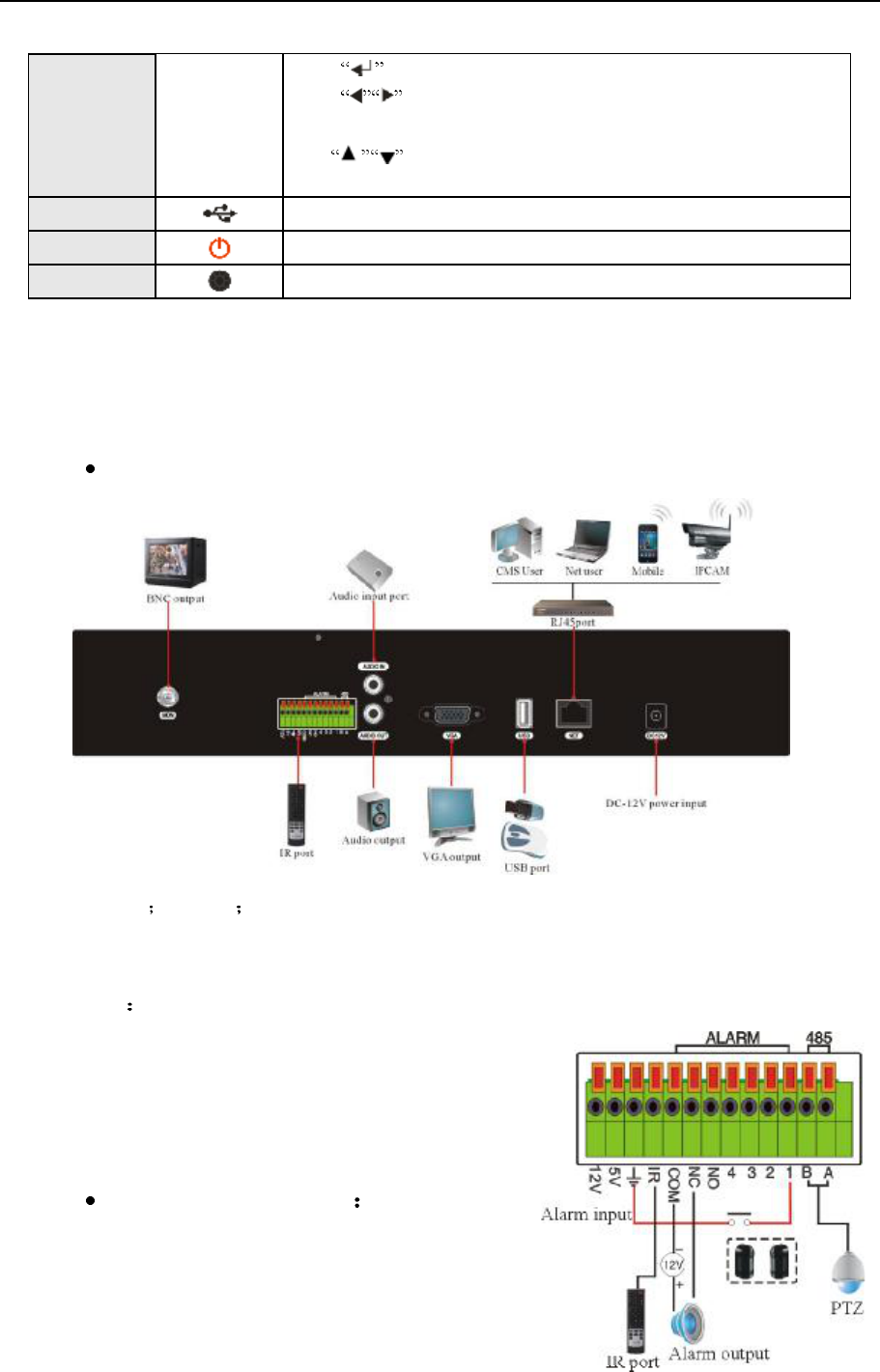
B. Rear panel
1) RS-485 ALARM IR.
2) Audio in/out
3) VGA
4) USB Connect to USB device to upgrade, backup; connect to USB mouse.
5) Net port.
6) BNC output
7) Power
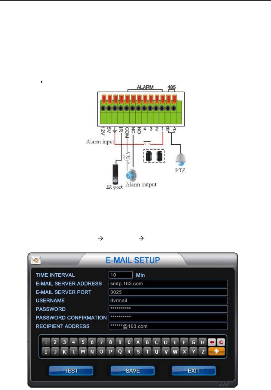
A. Alarm interface
NVR&IPCAM USER MANUAL V1.0
10
4 channel alarm in 1 channel alarm output.:
The above picture shows a typical alarm in /out connection way. In order to make
the NVR work well, it must connect to the ground as the above picture.
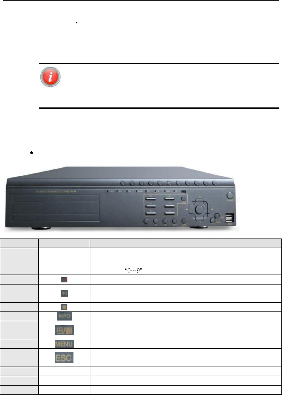
B Front panel
NAME ICON Function
NO. keys 0-9
X+
a) Switch channels;
b) Input password;
c) X+ with could switch from 10-19
Record Record
Play Press it
to pop up search menu, select the file to play; press it in play mode to
pause.
Stop Stop play or record.
INFO
Press it to popup information menu; press it again to enter into Log list.
Split Switch the split screen.
Menu
Menu; exit from sub-menu; input password.
Exit Exit; press it in live mode to hide the mouse icons.
Z+/Z- Zoom+/- Press it to zoom in/ out in PTZ mode.
F+/F- Focus+/- Press it to make focus+/-
I+/I- Iris+/- Press it to make Iris+/-
NVR&IPCAM USER MANUAL V1.0
11
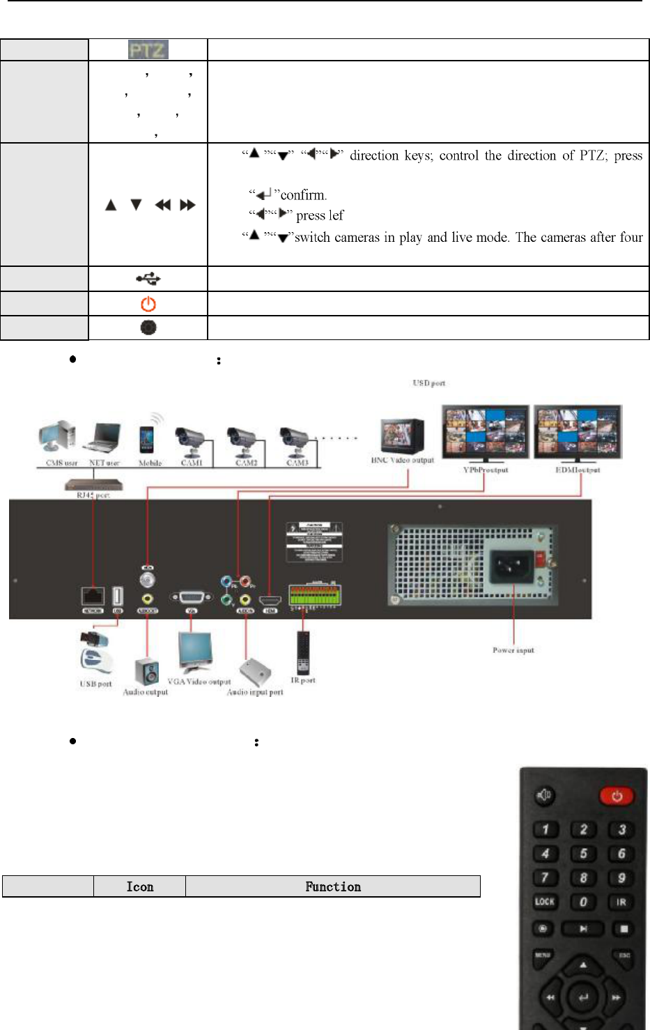
PTZ
Press it to control speed dome.
Light
POWER HDD
REC ALARM
NET PTZ
LOCK IR
They will be on in working mode.
Direction &
confirm
a)
left/ right key to play fast forward/ rewind in play mode;
b)
c)
t/ right key to play fast forward/ rewind in play mode;
a)
should be switched via these two keys.
USB2.0 Connect to USB device to upgrade, backup; connect to USB mouse.
Power Power on/off
IR
Receive the signal of remote controller. It could not be covered.
B Real panel
B alarm interface
The same as A alarm interface.
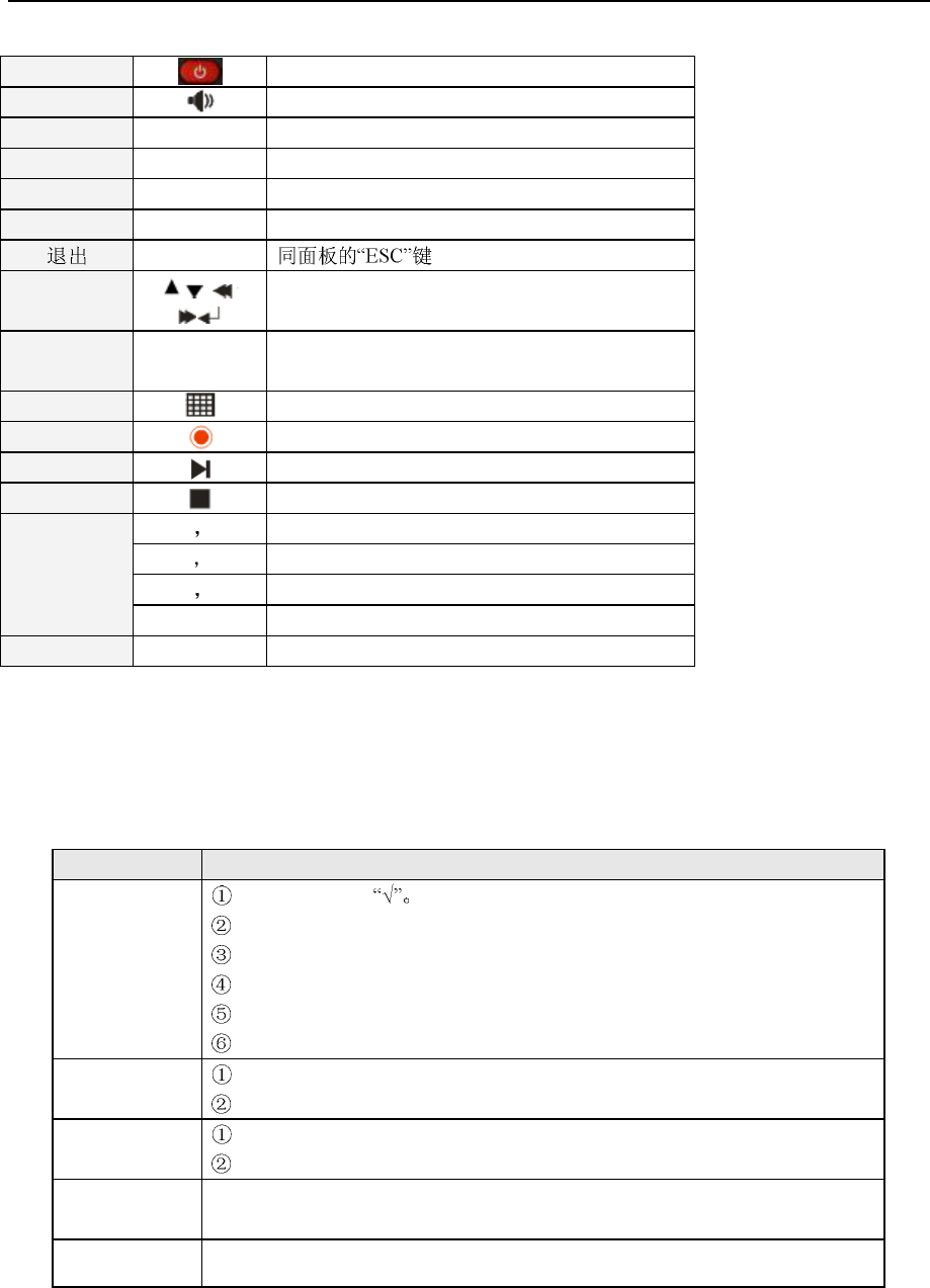
1.5 Remote controller
Icon Function
NVR&IPCAM USER MANUAL V1.0
12
Power
Press it to turn off thr NVR.
Audio
Press it to pop up audio setup menu.
NO. keys 0-9 Same as front panel.
Lock LOCK Lock the NVR.
IR IR Turn on/off IR.
MENU MENU Enter in to menu.
ESC
Direction &
confirm
Same as front panel.
INFO INFO
Press twice to popup information menu. Press
three times to popup log list.
Split
Switch the split screen.
Record
Record
Play/pause
Play and pause.
Stop
Stop play or record.
PTZ control
I+ I- Press it to make iris+/-.
F+ F- Press it to make focus+/-.
Z+ Z- Press it to make zoom +/-.
Auto Control speed dome rotate automatically.
PTZ PTZ Press it to control PTZ.
1.6 Mouse
Move the cursor to mouse icon will popup the prompt.
Operation Function
Left click
Select or cancel
Input password in login interface.
Select each function.
Full screen in live mode.
Switch channels.
Switch the items.
Right click To popup the mouse icons.
Switch channels and items.
Move cursor Move the cursor.
To pop up the mouse icons and prompt.
Drag the mouse
To select the mark area in camera settings. To select motion detection area in
motion alarm. Digital zoom in live or play mode in single screen.
Mouse wheel Switch the items in menu.
NVR&IPCAM USER MANUAL V1.0
13
1.7 Live view
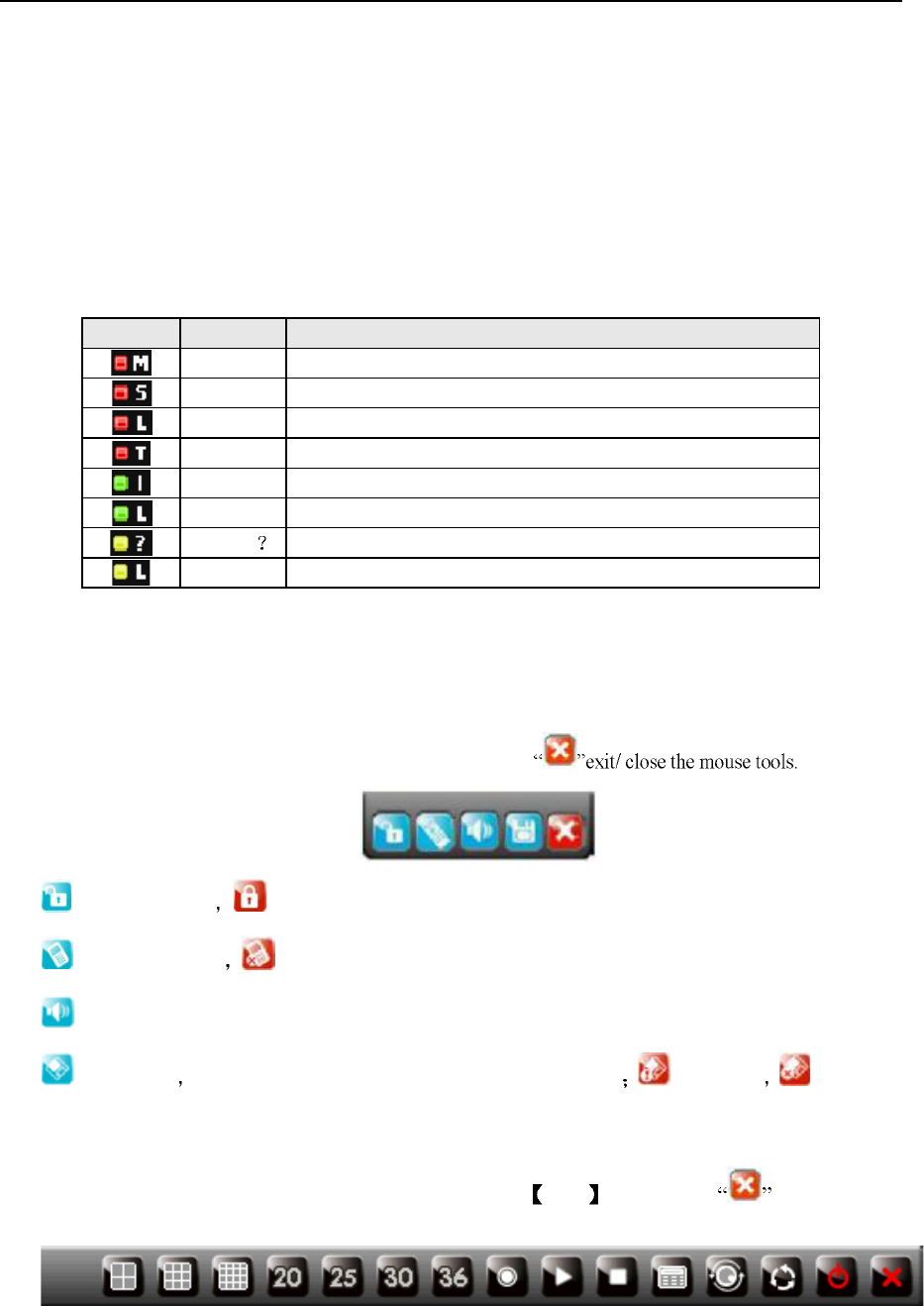
1.7.1 Live mode icons
Turn on the NVR to view the live image. It will show the date, time and camera name and record
mode in the screen.
Note: It need to press record key to start schedule record.
Icon color Description
Red M Under motion recording
Red S Under alarm recording.
Red L Video loss during recording
Red T Under timing recording.
Green I Waiting for event to activate recording
Green L
Video loss during waiting recording
Yellow
Have video input but no recording
Yellow L
No video input and recording.
1.7.2 Mouse tools
Mouse tools in top-right of the screen:
Press INFO key or right click the mouse to pop up the mouse tools.
Switch the users. lock. Click it to log in via input password.
Remote controller No signal of remote controller.
Control audio.
Information check the record mode, HDD mode and network mode HDD is full no HDD.
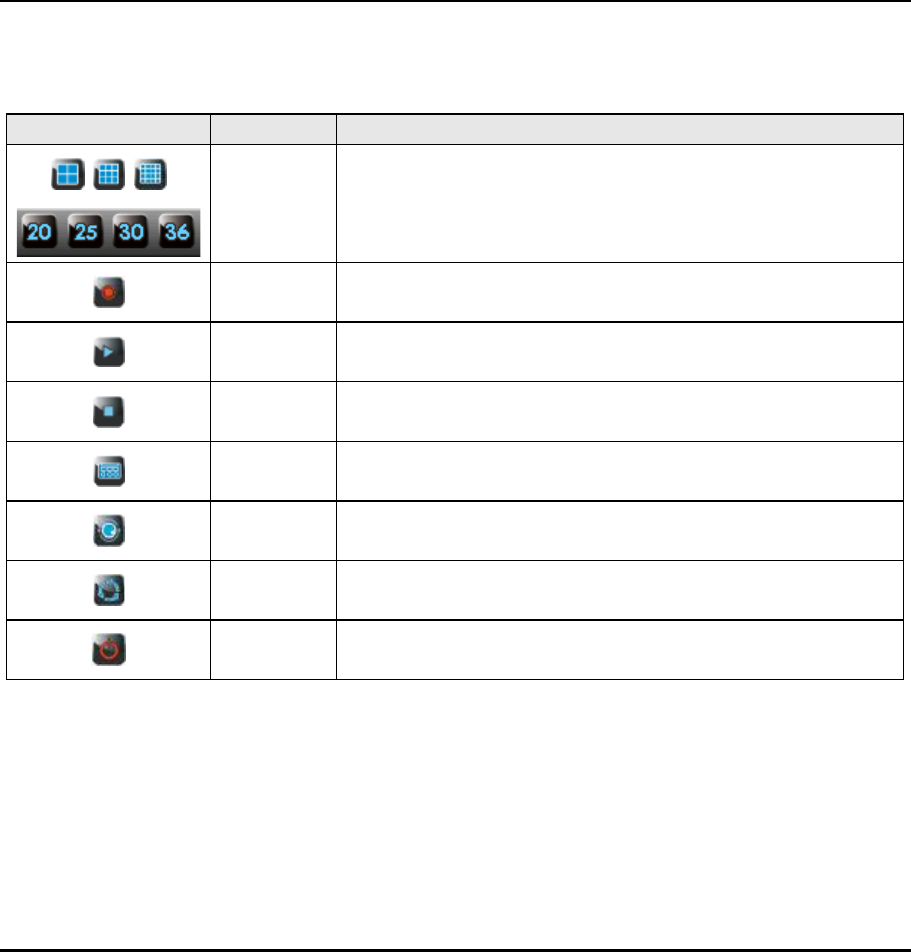
Mouse tools in bottom of the screen:
Right click the mouse to popup the mouse tools. Press ESC key or click to exit. Take
32ch NVR as example.
NVR&IPCAM USER MANUAL V1.0
14
Icons Name Description
Split Switch the split screen.
Record Record
Play Click it to popup search menu.
Stop Stop play or record.
Menu Enter into menu.
PTZ PTZ control.
SEQ Switch the channels automatically/ sequence.
Power Click it to popup the power prompt.
2 Operations
2.1 Turn on the NVR
Please check the voltage is fit for the NVR.
Please check the connection with other device is right or not.
Please insert the power line.
The power light is red after the NVR is power on.
NVR&IPCAM USER MANUAL V1.0
15
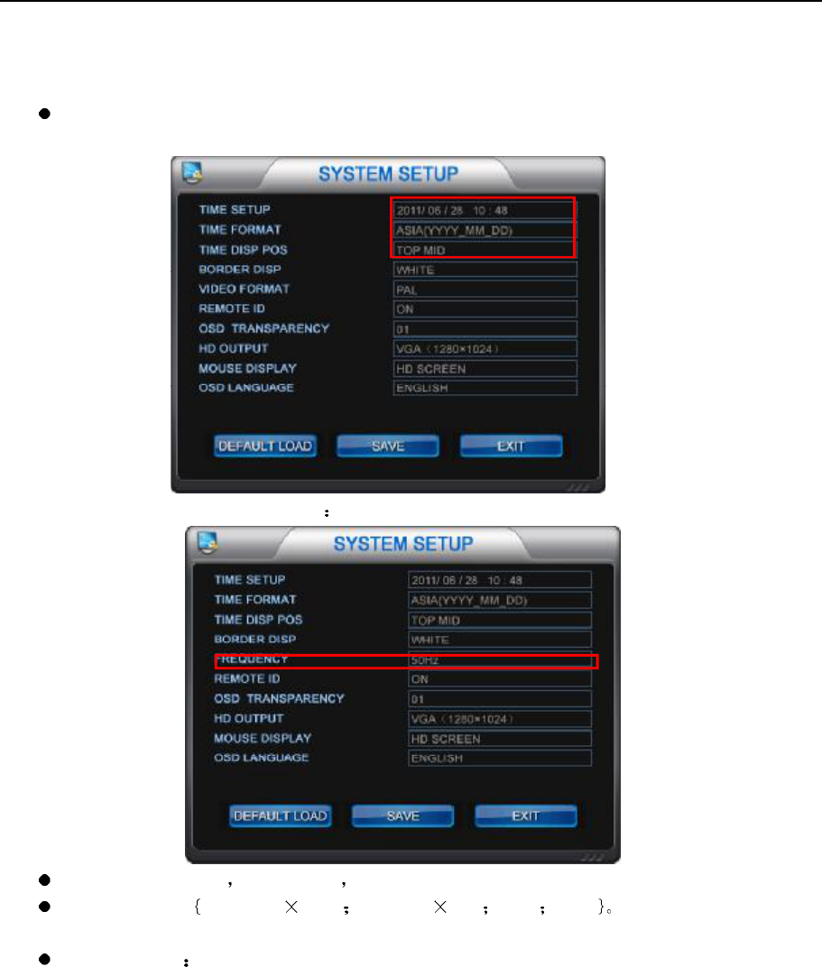
2.2 System setup
System time setup
Select "SYSTEM" in main menu to enter into SYSTEM SETUP interface.
The system menu of 720P/1080P resolution
Frequency: 50/60Hz 50Hzfor PAL 60Hz for NTCS.
HDMI output: VGA(1280 1024) VGA(800 600) HDMI YPbPr It should be corresponding
to the monitor.
Mouse display To select CVBS or HD monitor.
NVR&IPCAM USER MANUAL V1.0
16
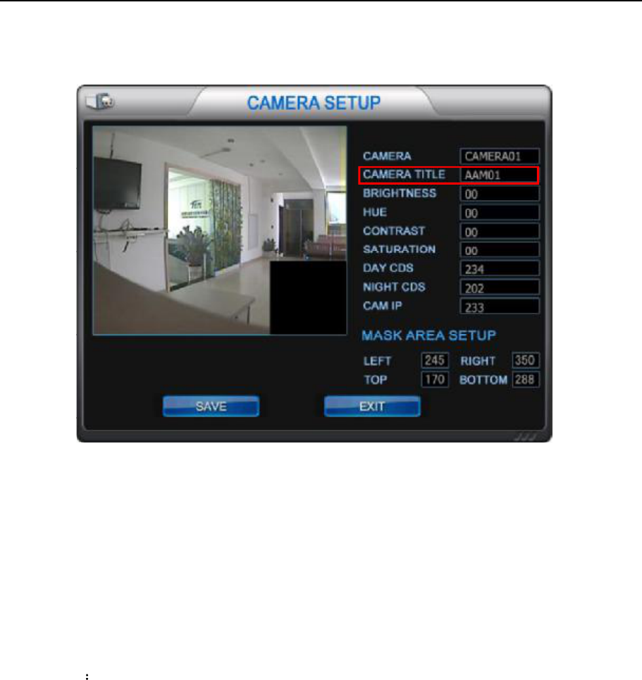
2.3 Camera setup and area mark setup
2.3.1 Change the camera name
Move the cursor to the letters, left/click the mouse to change the camera name.
2.3.2 Area mark setup
Drag a black square to hide some privacy part.
Operation way
Step one select the channels.
Step two drag the mouse to setup the square area.
Setup the left/right/up/down border
Left Click the mouse in the mark area to cancel the mark. Setup the place of left/right/up/down to modify
the area.
NVR&IPCAM USER MANUAL V1.0
17
2.4 Alarm setup
Example for alarm setup:
Channel 2
22:20 to 7:10next day.
It will alarm when the sensor feel somebody passed. The buzzer in the NVR will beep and send email.
Operation steps
Step one, connection
Note, If connect the alarm for NVR, please connect the alarm in port of the IPCAN with the ground; or it will
continue to alarm when schedule alarm happened. If connect the alarm for IPCAM, then please connect the
alarm in port of the NVR to the ground.
Step two, email setup
Firstly confirm the network connection of the NVR is well.
Then please follow the instruction: Menu network setup- email
NVR&IPCAM USER MANUAL V1.0
18
1) Time interval: To set the time interval for sending email. It should be in denomination of minutes.
2) Email server name: To set the email server for sending email.
3) Email server port: To set the email server port. Generally the SMTP port is 25.
4) User name: It's the email user name.
5) User password: It's the email password.
6) Password confirmation: To confirm your email password.
7) Receiving address: It's the email address.
Operation way: moving mouse cursor to the each box and left click the mouse to edit.
s right in network setup.
If the test email is failed, please check the setup of sending email in the web. It must open SMTP service
for the email.
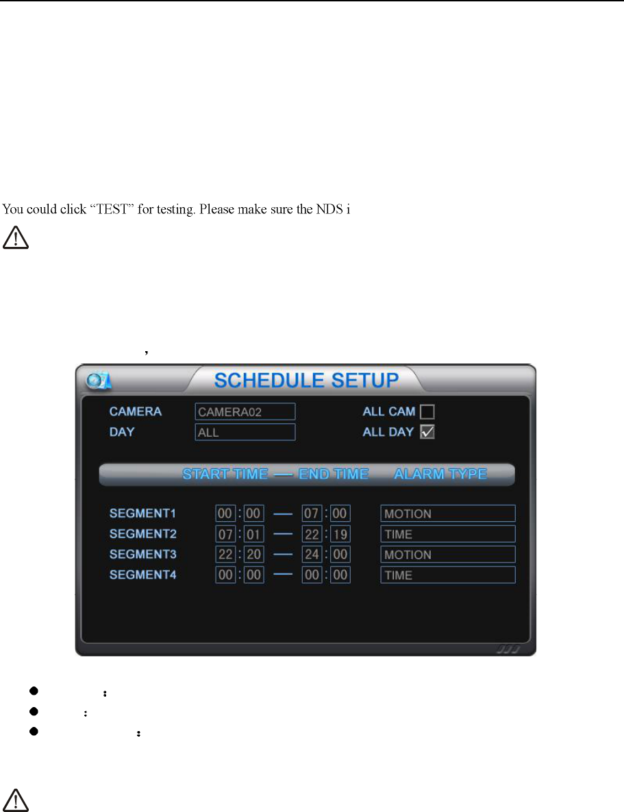
Step three, schedule setup.
Menu-->schedule setup
Camera select a channel or all channels.
Date set the date for recording. It could be set four time segment.
Time segment set the recording type. (time, motion, alarm, motion + alarm)
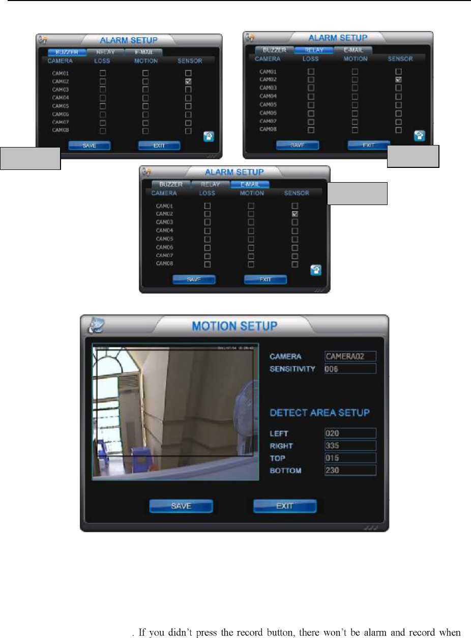
Step four, alarm setup
It no need alarm for motion, just set for sensor alarm; or the alarm will happened frequently.
NVR&IPCAM USER MANUAL V1.0
19
Step five, set recording area and sensitivity for motion recording.
Sensitivity: Select number 1-50 for motion sensitivity. Generally speaking, numerical value higher, the
sensitivity better.
Detection area: Select the motion detect area. Drag the mouse to select the area. When it detects there is
movement in this area, the boarder color will turn red.
Step six, start recording
Press record button to start
motion happened.
BUZZER
RELAY
E-MAIL
NVR&IPCAM USER MANUAL V1.0
20
2.5 Record operation
2.5.1 Preparation for recording
Connect all relevant device and power on for them. Confirm that there are video in and audio in.
Press INFO key to check the hard disk information. If the left capacity of the HDD is not enough, please change
it or open the overwrite function in HDD management menu.
Enter into schedule setup menu to set the relevant setup.
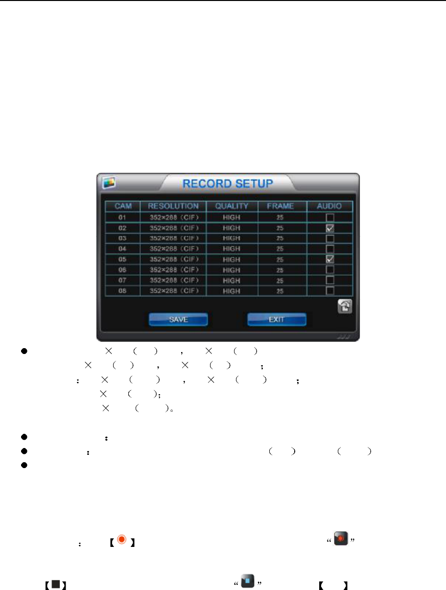
Enter into record setup menu to set record parameters.
Resolution: 352 288 CIF PAL 352 240 CIF NTSC
D1:704 576 D1 PAL 704 480 D1 NTSC
960H 960 576 960H PAL 960 480 960H NTSC
720P: 1280 720 720P
1080P:1920 1080 1080P
The system will restart after the resolution changed.
Quality (image) To set the image quality at high, middle and low.
Frame rate To modify the frame rate per second. 25fps PAL or 30fps NTSC
Audio: To set audio recording on and off.
2.5.2 Recording start and stop
a) Start recording: press key in front panel or use mouse to click the icon in mouse tool bar to
start record. Once start recording or HDD begin to write, the HDD indicate light will turn on.
b) Press key in front panel or use mouse to click the icon or press ESC key to stop record.
NVR&IPCAM USER MANUAL V1.0
21
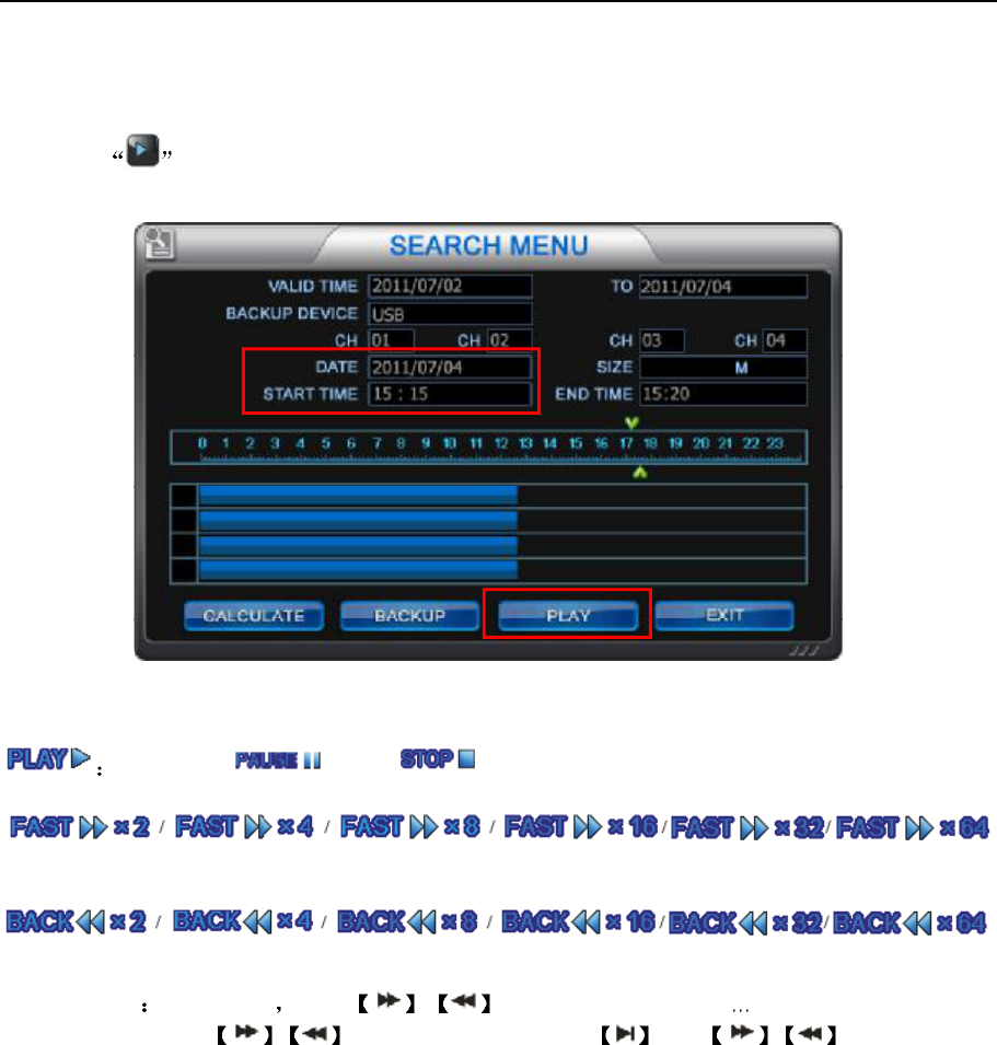
2.6 Playback
Click icon to enter recording search interface. You could search the recording file and backup the file
into another device. Also you could search for a video file to playback.
You could see the play status prompt in the bottom of the screen.
normal play pause stop
the speed of fast forward
The speed of fast rewind.
Operation way in play mode press / key once/twice/three times ..six times to play faster
and faster. Then press /again to play normally. Press and / to play forward
or rewind one frame.
NVR&IPCAM USER MANUAL V1.0
22
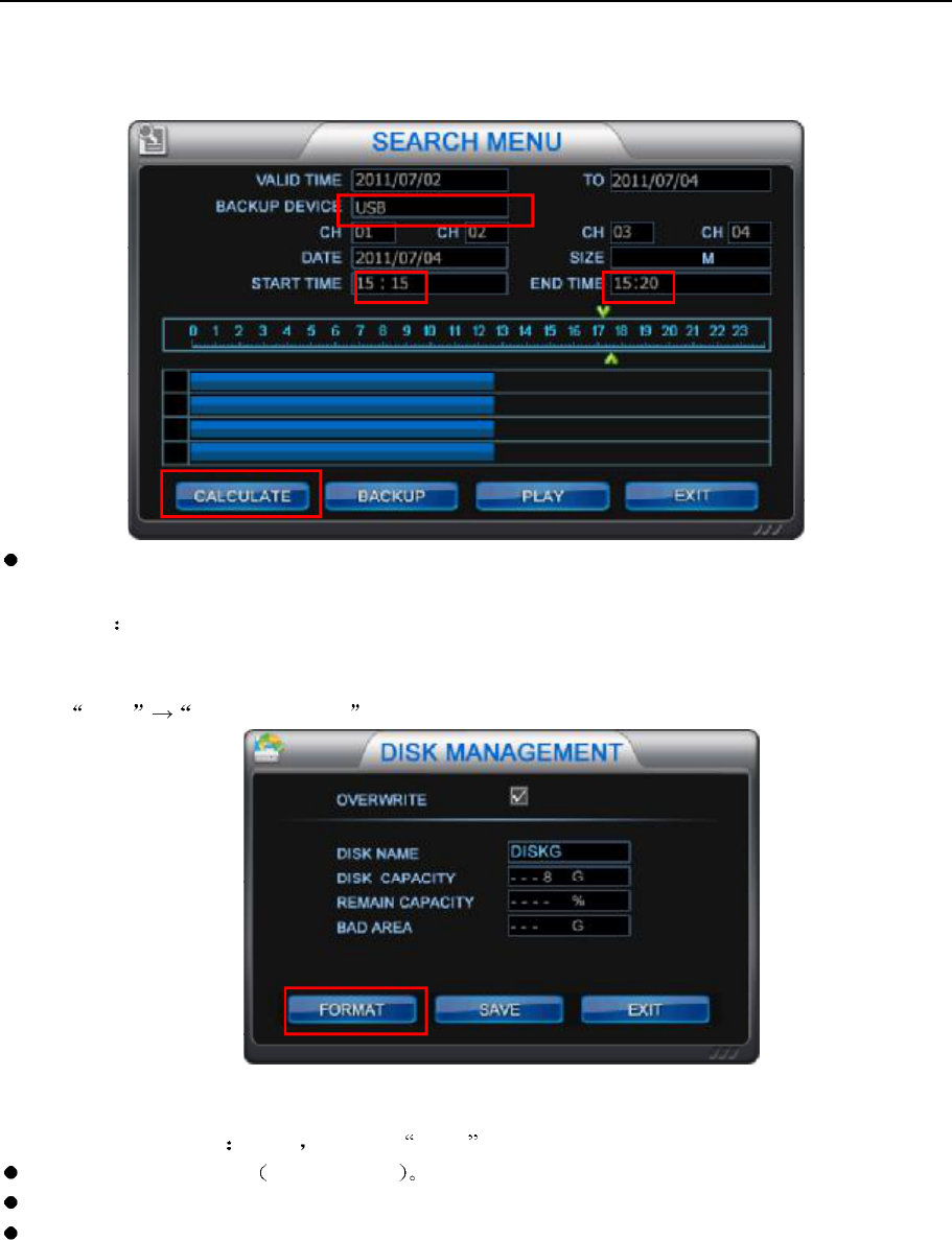
2.7 Backup
Select backup device
USB / CD(500M) / DVD 1.5G / MINI CD(180M)
USB backup Less than 30G. If the usb disk could not be read, please format it firstly.
USB format way:
Insert the usb disk into US port of NVR.
menu HDD management
Select the disk name disk A then click format .
Select backup channels 4 channels max
Select backup time: select the begin time and end time.
Calculate: To calculate the video file's capacity which you want to backup. Before your backup, please try to
proceed this operation
Note: not support mobile HDD backup.
NVR&IPCAM USER MANUAL V1.0
23
2.8 Audio setup
Press AUDIO key in front panel or in the remote controller or click to enter into audio setup
menu.
monitor : Mute, client, CH1-CH9 optional.
Broadcast NVR transfer the live audio to client or cameras via pickup device. If client/ some
channel is selected, the audio will be transfer to the client/ some channel. is selected.
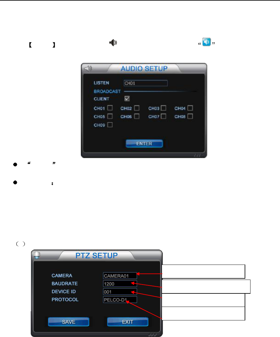
2.9 PTZ setup
1Set the parameters in PTZ setup menu firstly.
Select the channel connected
Select the baud rate of the speed
Set the ID for the speed dome
Select the communication
NVR&IPCAM USER MANUAL V1.0
24
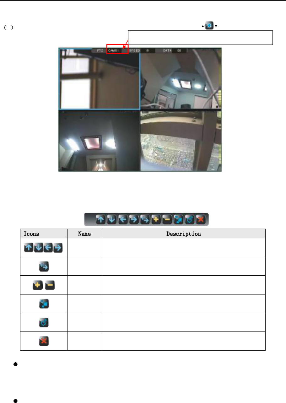
2After speed dome setup, please enter PTZ setup. Press the [PTZ] key or click to enter it.
Then it will display "PTZ: CAM01 SPEED:16 DATA:00" in the screen. It means DVR is under PTZ status now. Press
[PTZ] or [ESC] again to exit PTZ interface. When DVR is under PTZ status, it will display the mouse tool bar as
below:
Icons Name Description
Direction
key to move speed dome up, down, right and left.
Rotate
To make speed dome rotate automatically.
Press it again to stop rotating.
¦±±³ Zoom in and zoom out
preview
To check the preset data already saved.
Set To make preset setup.
Close
Shut off PTZ and exit PTZ interface.
Modify parameters:
You could use mouse or remote control to modify the preset data. Select the item which you want to modify
by press [SPOT] key on remote control or click the item directly by mouse. Then modify the data by left/right
click by mouse.
Preset setup:
Select the channel which is connect with speed dome
NVR&IPCAM USER MANUAL V1.0
25
a) Select image point in selected camera by keys. Set a number for the image in
DATA , such as 01 then click to finish the setup.
b) To view of image point which has been saved, you could select the corresponding number in DATA
then click to view.
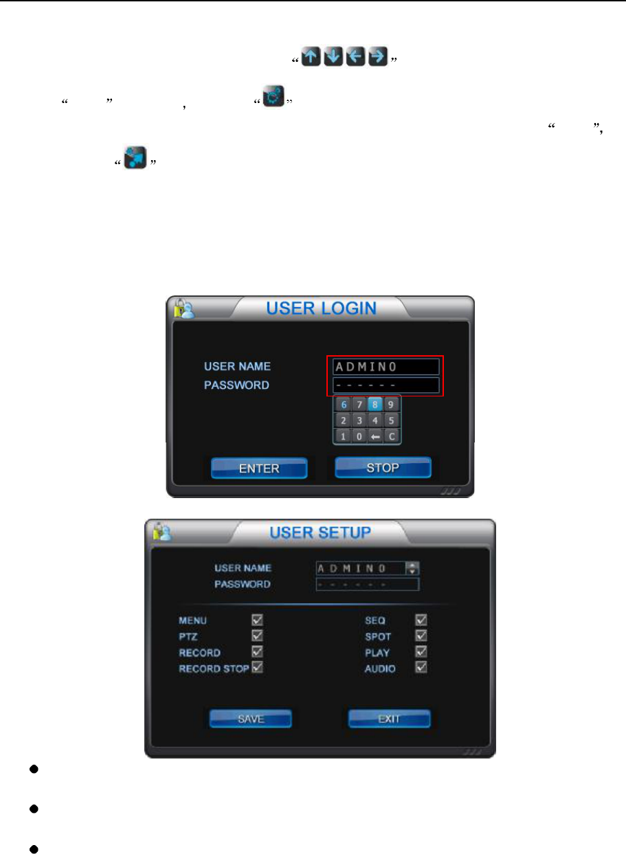
2.10 User setup
Before enter USER SETUP interface, you should enter USER LOGIN interface and type the correct password
first.
User name: To select administrator and users. There are 4 user name , ADMIN0, USER01, USER02 and
USER03. ADMIN0 is default one.
Password: To set user's password. The default password is 000000 for ADMIN0, 111111 for USER01,
222222 for USER02 and 333333 for USER03. And password is changeable by users.
Authority setup: As administrator, you could enter USER SETUP to grant normal user authority to make
setup.
NVR&IPCAM USER MANUAL V1.0
26
Unlock setup: If the DVR was locked, please click the " " on right top of screen. Then it wills popup the interface
of USER LOGIN. Type the user name and password to unlock the DVR. Then the icon " will turn to blue " ".
2.11 User shift
Please enter USER LOGIN interface to shift the user and type correspond password.
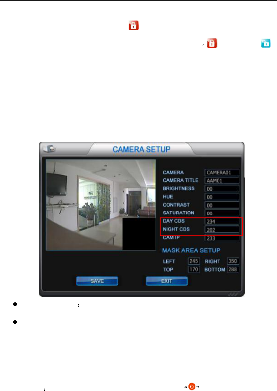
2.12 Night view setup
Enter into camera setup:
Day light perception Images switch to day mode when the light intensity is greater than the value,
the image is color. Default one is 234.
Night light perception: Images switch to night mode when the light intensity is smaller than the
value, the image is white and black. Default one is 202.
2.13 Turn off the NVR
Soft turn off exit from all operations and back to live mode. Press key in front panel or remote
NVR&IPCAM USER MANUAL V1.0
27
controller or click the mouse icon to popup turn off prompt, select OK to turn off the NVR. press
key three seconds to restart the NVR.
Hard turn off Pull the power line directly.
Abnormal crash: If the NVR restart five times failed in one hour, it will keep crash, the buzzer will beep. Please
cut off the power and power on again.
2.14 The status of HDD
Press INFO key in live mode, you could see the following icons,
The system information and HDD is full.
No HDD.
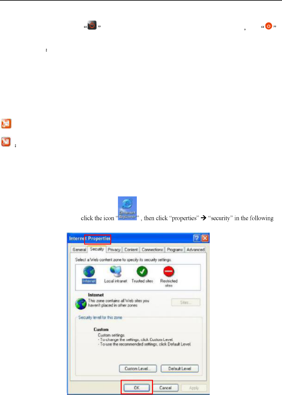
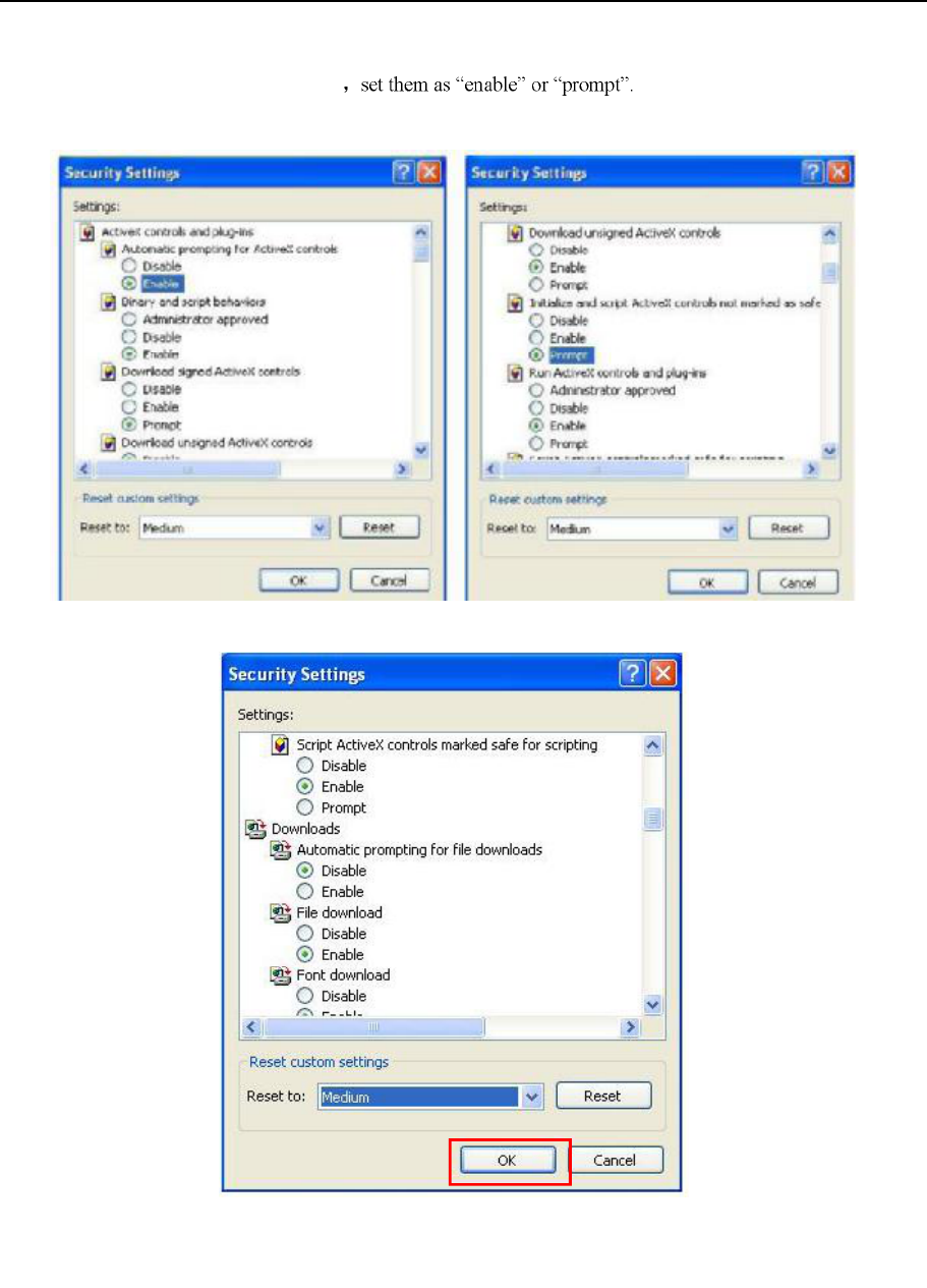
2.15 IE connection
Operation steps:
Step one: click security, Right-
dialog box.
NVR&IPCAM USER MANUAL V1.0
28
Step two, check all items in ActiveX
NVR&IPCAM USER MANUAL V1.0
29
Step three, IE ActiveX download address http://www.fab111.com:82/ or download it from the NVR IP,
e.g. http://192.168.1.220:82/ 82 is the IE port set in Network menu. it need to do port forwarding in the router
when download IE ActiveX controls from WAN.
Step four, it will popup login interface after the IE ActiveX controls was download.
There are four login way.
a) NVR LAN IP with DVR port, e.g.: 192.168.1.220:6802.
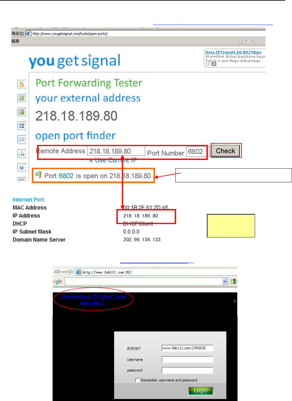
WAN connection:
Firstly confirm the WAN IP in the router is the real and useful IP. It must to do port forwarding for the NVR
port in the router. Then check the setting is successful or not in http://www.yougetsignal.com/tools/open-ports.
b) Router domain name with DVR port. E.g.: avdf.dyndns.com:6802. It need to apply for a domain name
in the web and fill in the domain name in the router.
c) Router WAN IP with DVR port. E.g. 20.30.40.50:6802. If the IP is fixed, this way could be used.
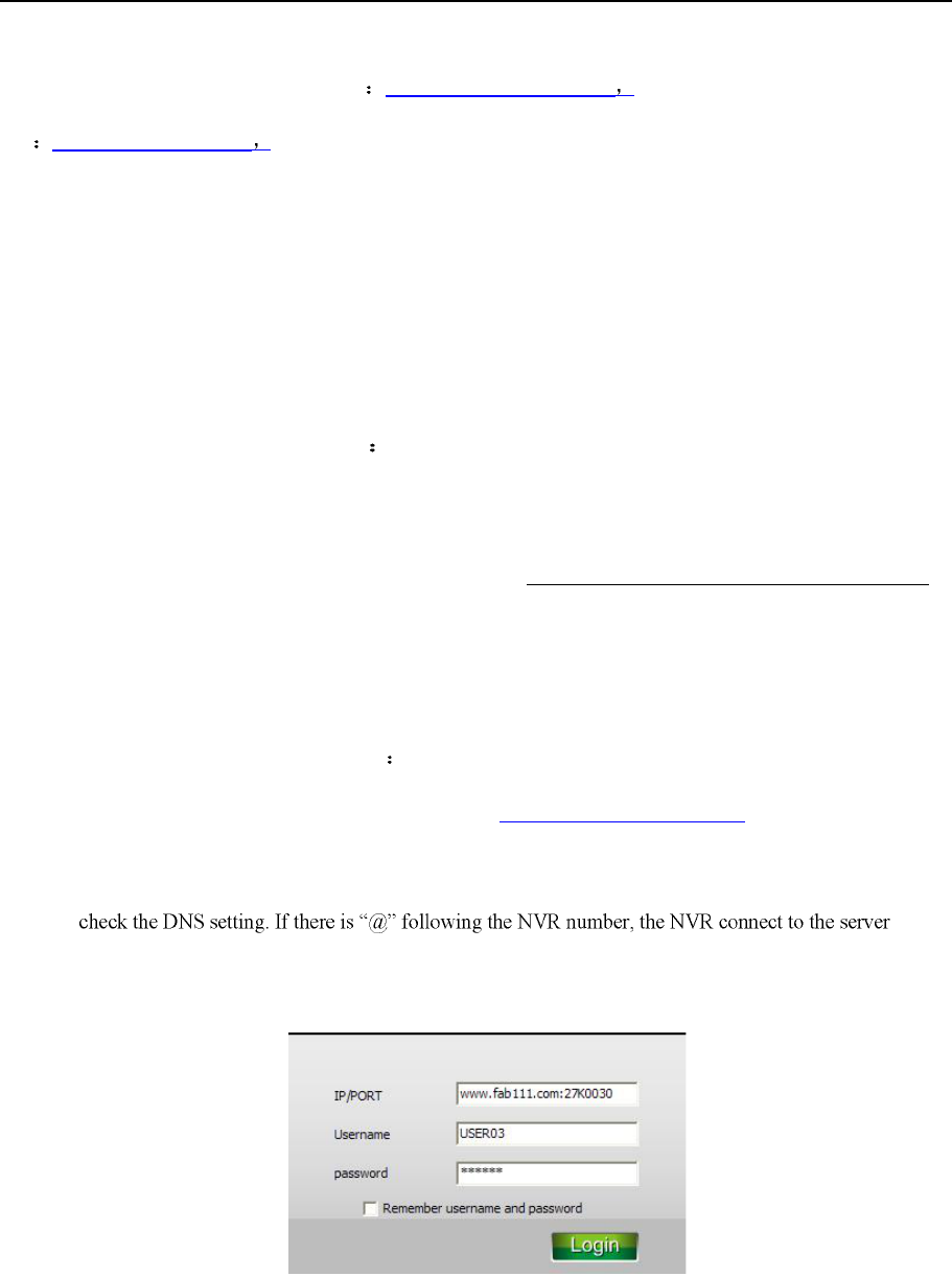
d) Free supply domain name with NVR number. E.g. www.fab111.com:27K0030. Please select DDNS in
network setup menu of NVR. Then you could check the DDNS information in INFO menu. Please
successfully.
NVR&IPCAM USER MANUAL V1.0
30
Click the left top link or http://www.fab111.com:83 to download the latest CMS and iMac
CMS. CMS support strong function.
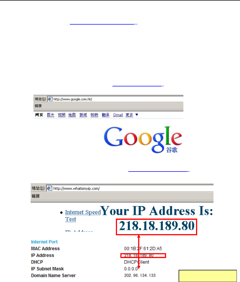
2.16 NVR networking example
1. Connect the NVR net cable with the PC. Type in http://www.google.com in IE address bar. Check the WAN
connection is well or not. Then you could see the page.
2. Confirm the router IP is the real and useful IP. Type in http://www.whatismyip.com in the IE address bar.
The IP shows here must be the same as the router IP. If no, it is not the real IP.
It is Router interface
NVR&IPCAM USER MANUAL V1.0
31
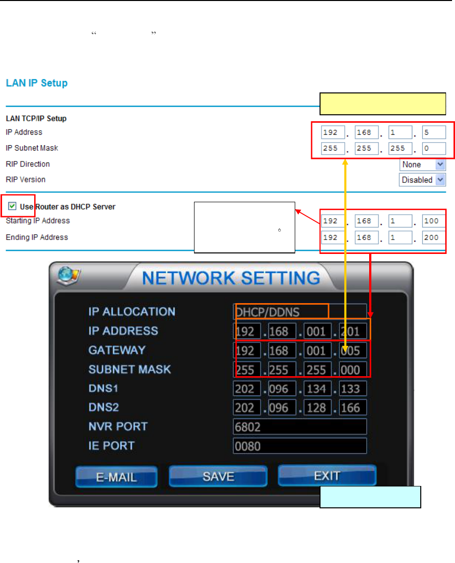
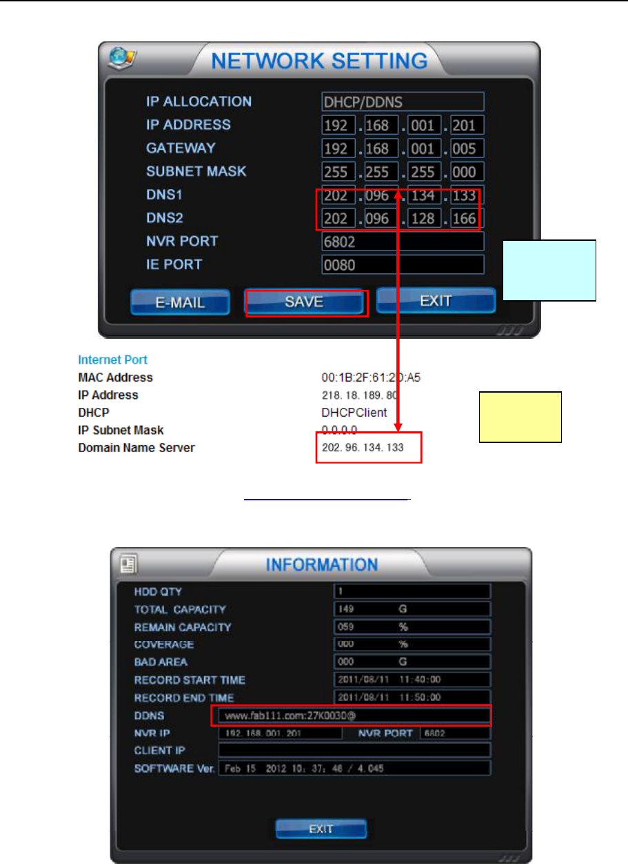
3. Set the IP item as DHCP/DDNS in network setup menu in NVR. If the DHCP in the router is open, the
NVR will get the IP from the router automatically. Please change the IP, it should out of the range of DHCP.
Check DNS IP it should be the same one in the router.
NVR IP address must
be out of this range
It is Router interface
It is NVR interface
NVR&IPCAM USER MANUAL V1.0
32
4. Open INFO menu in NVR. It will show www.fab111.com:27K0030@ in DDNS item. If no @, the
connection between NVR and server is failed. Please exit and enter into the INFO menu again after one
minute. If there is no @ again, please check the DNS setting of NVR is right or not.
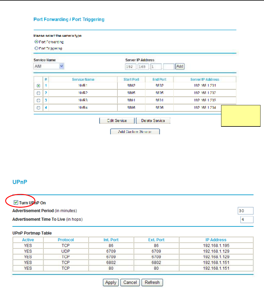
5. Set port forwarding in router. Set different port for different NVR and port forwarding separately.
It is router
interface
It is NVR
interface
NVR&IPCAM USER MANUAL V1.0
33
Open UPnP function in the router to fulfill the port forwarding of NVR automatically. It is suggested to
change the port in network setup menu after UPnP is open. And set auto port forwarding at once after save
the port. Click the refresh icon to see the latest IP and port.
It is Router
interface
NVR&IPCAM USER MANUAL V1.0
35
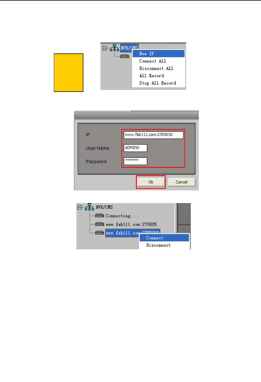
7. Open the MS client software, type in the domain name, NVR number, user name and password to test the
connection. If the connection is failed, please check with LAN IP.
Open the client software, right click NVR/CMS, select new IP, add it and connect it.
Note: the setting of router may not support WAN IP connection in local network, then the
connection via domain name and NVR number will also fail.
T
his is
client
software
interface

NVR&IPCAM USER MANUAL V1.0
36
FCC Caution.
§ 15.19 Labelling requirements.
This device complies with part 15 of the FCC Rules. Operation is subject to the following two
conditions: (1) This device may not cause harmful interference, and (2) this device must accept
any interference received, including interference that may cause undesired operation.
§ 15.21 Changes or modification warning
Any Changes or modifications not expressly approved by the party responsible for compliance
could void the user's authority to operate the equipment.
§ 15.105 Information to the user.
Note: This equipment has been tested and found to comply with the limits for a Class B digital
device, pursuant to part 15 of the FCC Rules. These limits are designed to provide reasonable
protection against harmful interference in a residential installation. This equipment generates uses
and can radiate radio frequency energy and, if not installed and used in accordance with the
instructions, may cause harmful interference to radio communications. However, there is no
guarantee that interference will not occur in a particular installation. If this equipment does cause
harmful interference to radio or television reception, which can be determined by turning the
equipment off and on, the user is encouraged to try to correct the interference by one or more of
the following measures:
-Reorient or relocate the receiving antenna.
-Increase the separation between theequipment and receiver.
-Connect the equipment into an outlet on a circuit different from that to which the receiver is
connected.
-Consult the dealer or an experienced radio/TV technician for help.
This equipment complies with FCC radiation exposure limits set forth for an
uncontrolled environment. This equipment should be installed and operated with
minimum distance 20cm between the radiator & your body.