ASUSTeK Computer 6218-A1 ADSL WIRELESS MODEM ROUTER User Manual paradyne Manual for EMI
ASUSTeK Computer Inc ADSL WIRELESS MODEM ROUTER paradyne Manual for EMI
UserManual.wiki
>
ASUSTeK Computer
>
6218 A1 User Manual
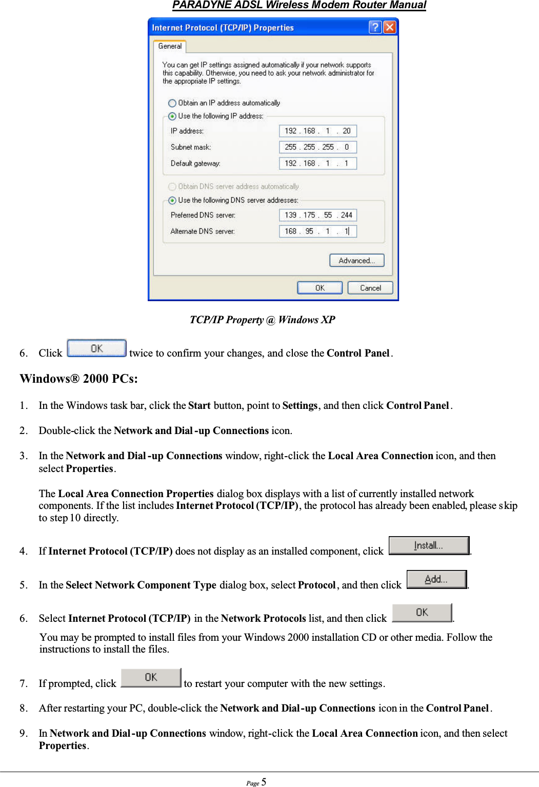
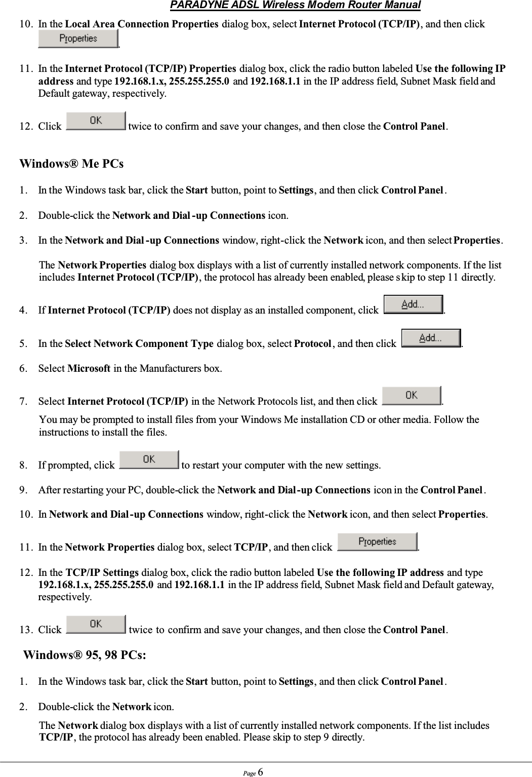
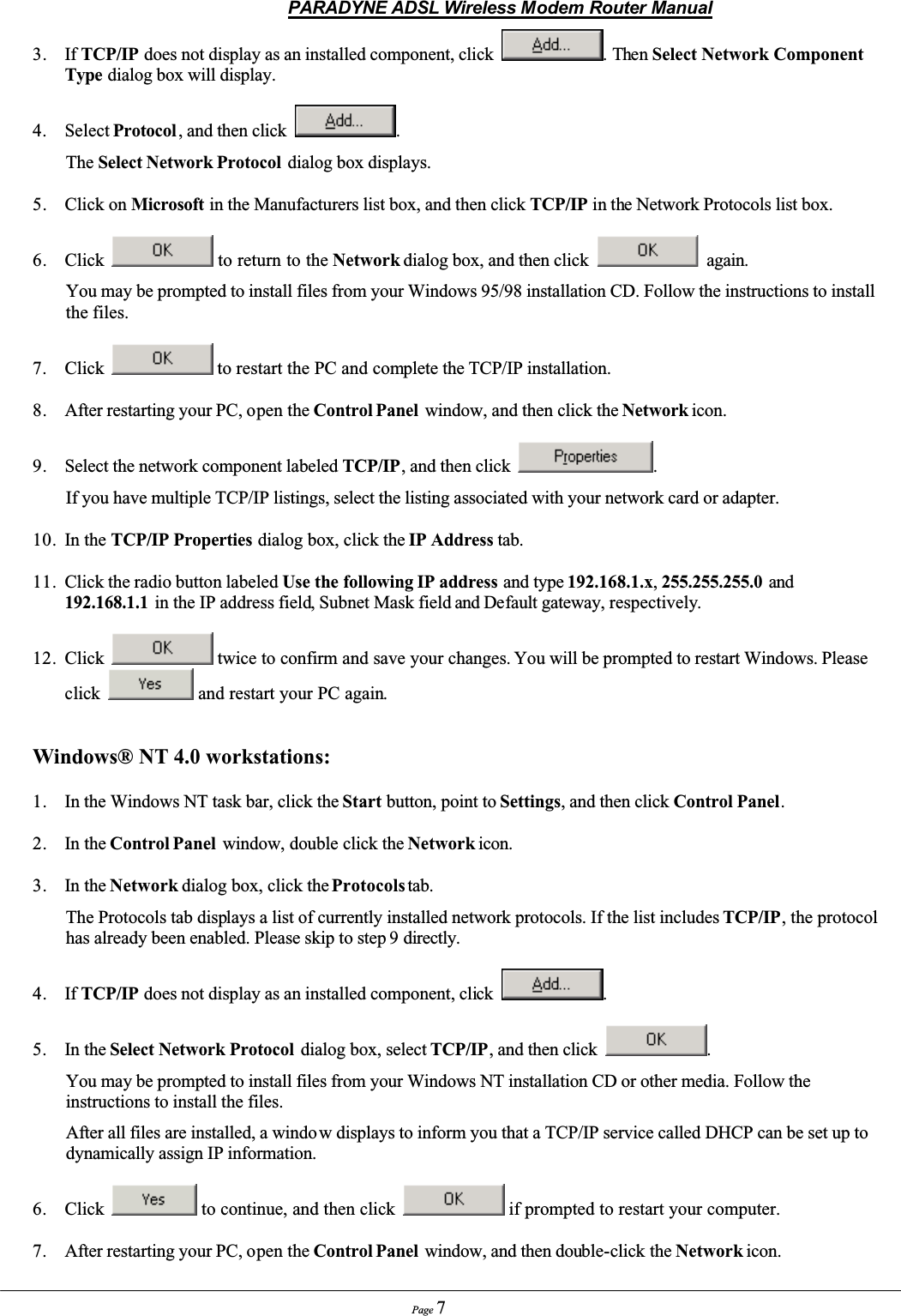
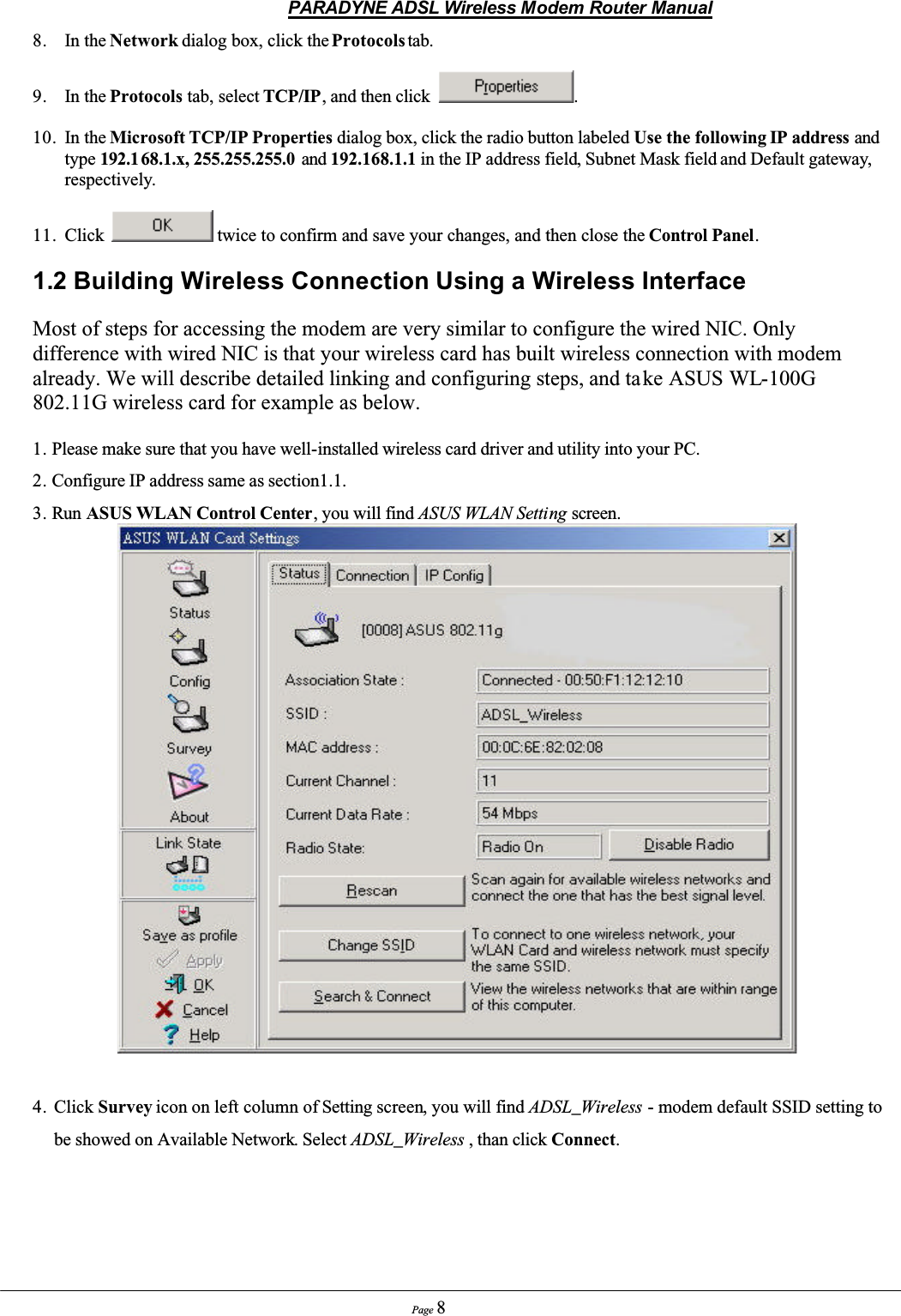
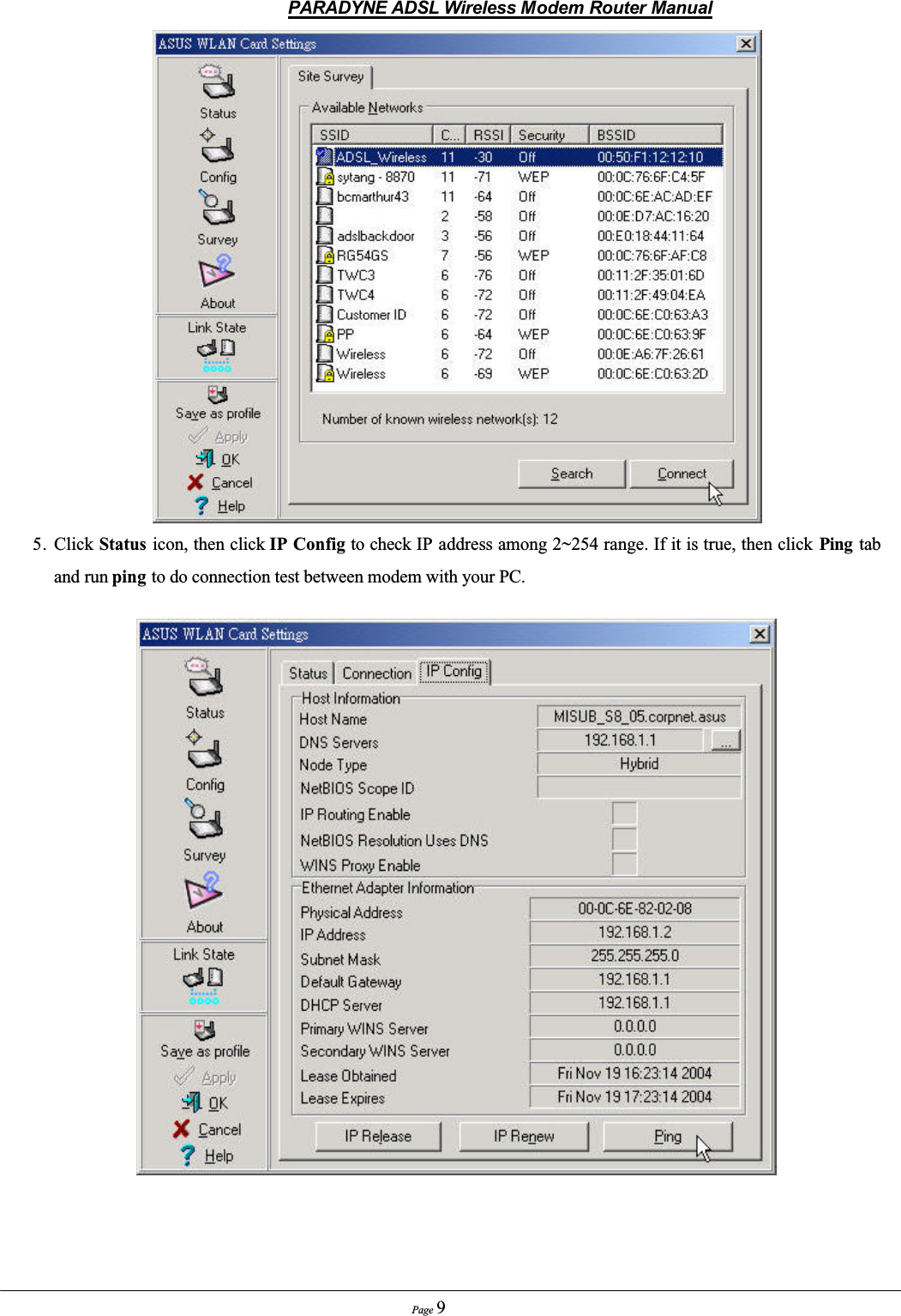
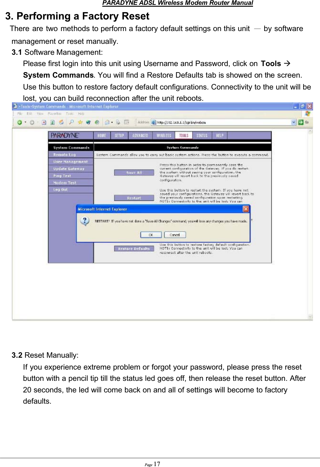
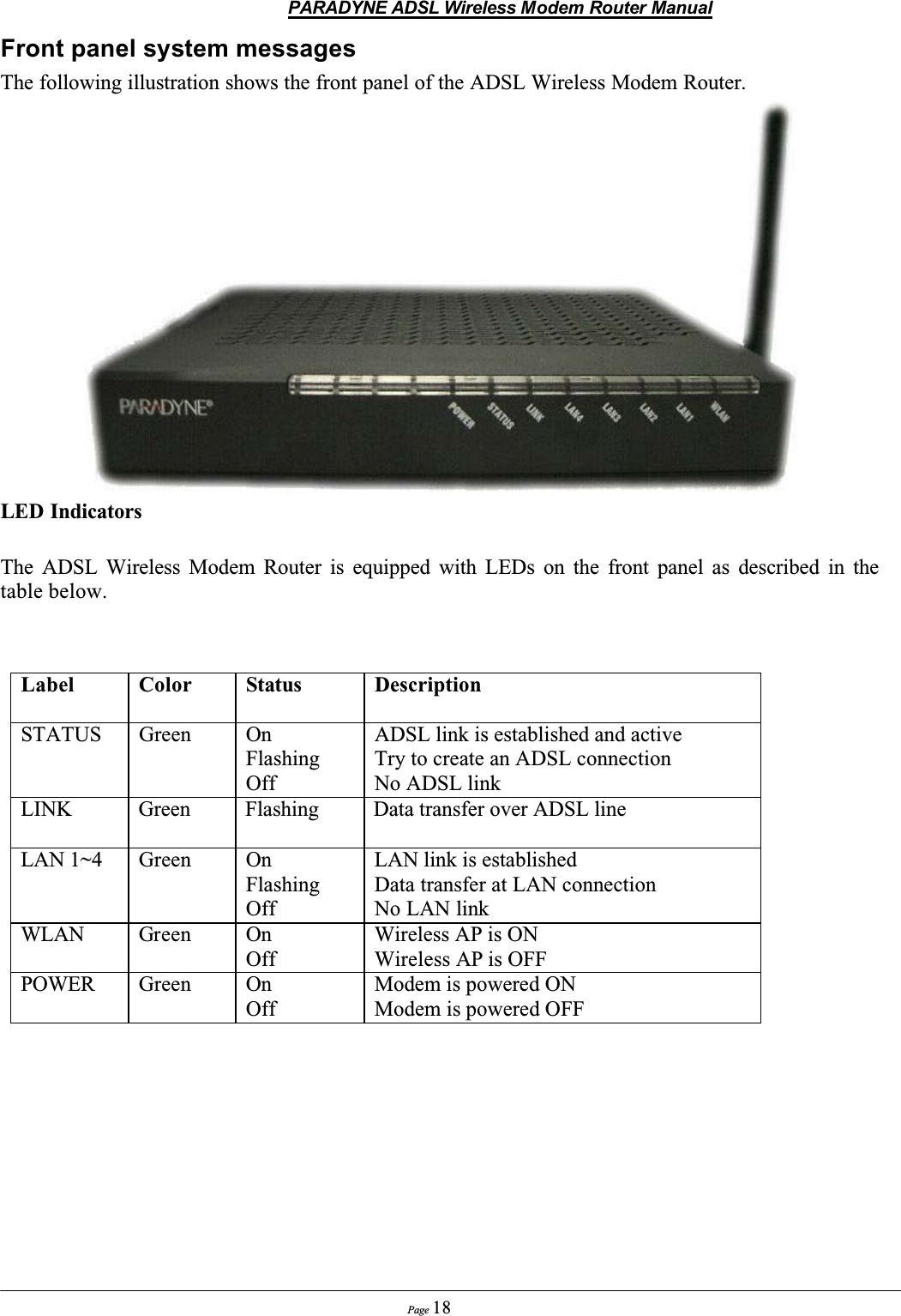
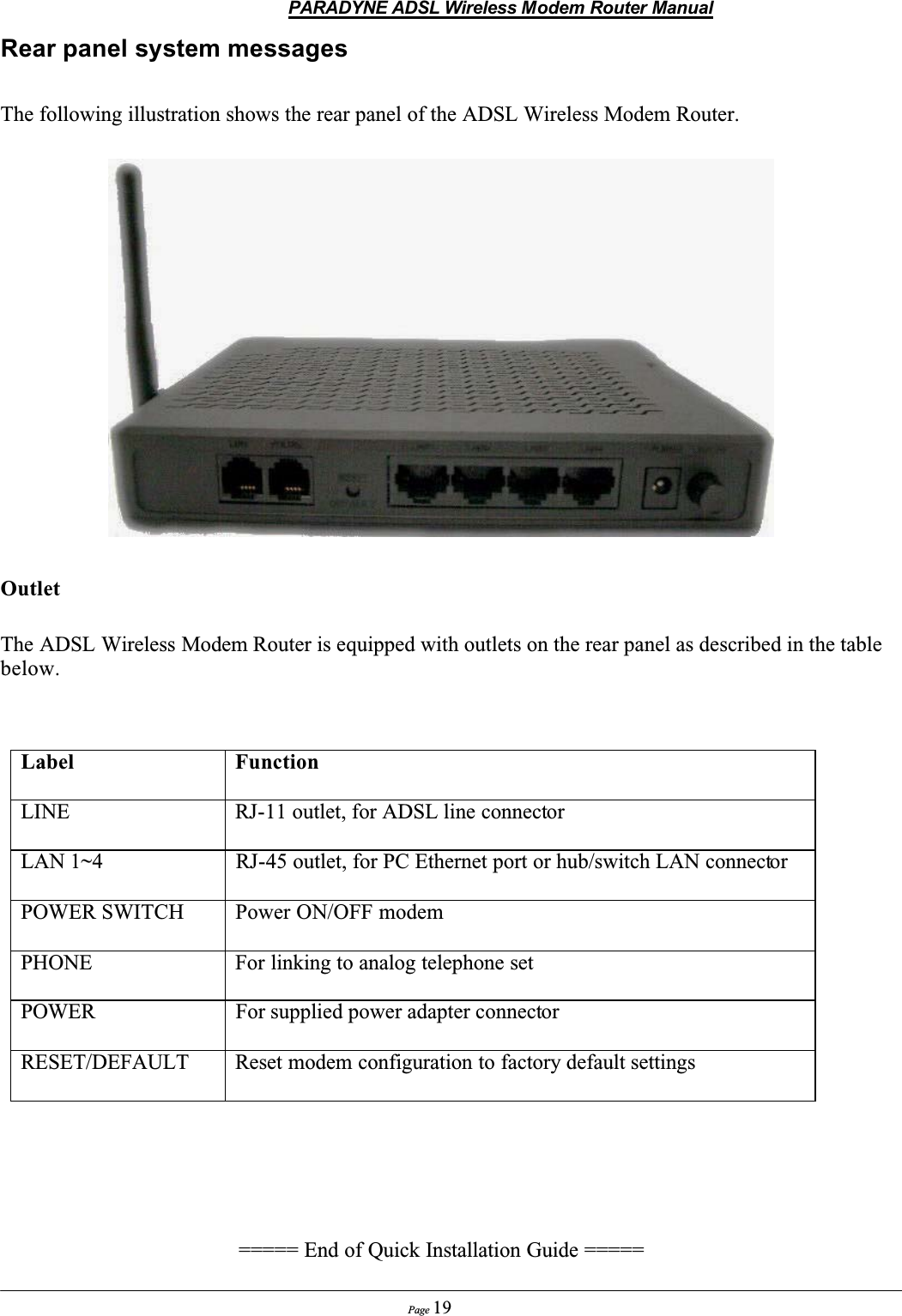
USERS MANUAL
Navigation menu
Upload a User Manual
Namespaces
Wiki Guide
HTML
PDF
Info
Views
User Manual
Discussion / Help
Navigation