ASUSTeK Computer 7265NG Wireless Network Adapter User Manual 7265NGW UserMan
ASUSTeK Computer Inc Wireless Network Adapter 7265NGW UserMan
UserManual.wiki
>
ASUSTeK Computer
>
7265NG User Manual
>
(7265NGW) UserMan
Contents
1.
(7265NGW) UserMan
2.
(7265NGW) UserMan_20141114
3.
(7265NGW) UserMan_Part 1
4.
(7265NGW) UserMan_Part 2
5.
(7265NGW) UserMan_20151231
(7265NGW) UserMan
Navigation menu
Upload a User Manual
Namespaces
Wiki Guide
HTML
PDF
Info
Views
User Manual
Discussion / Help
Navigation
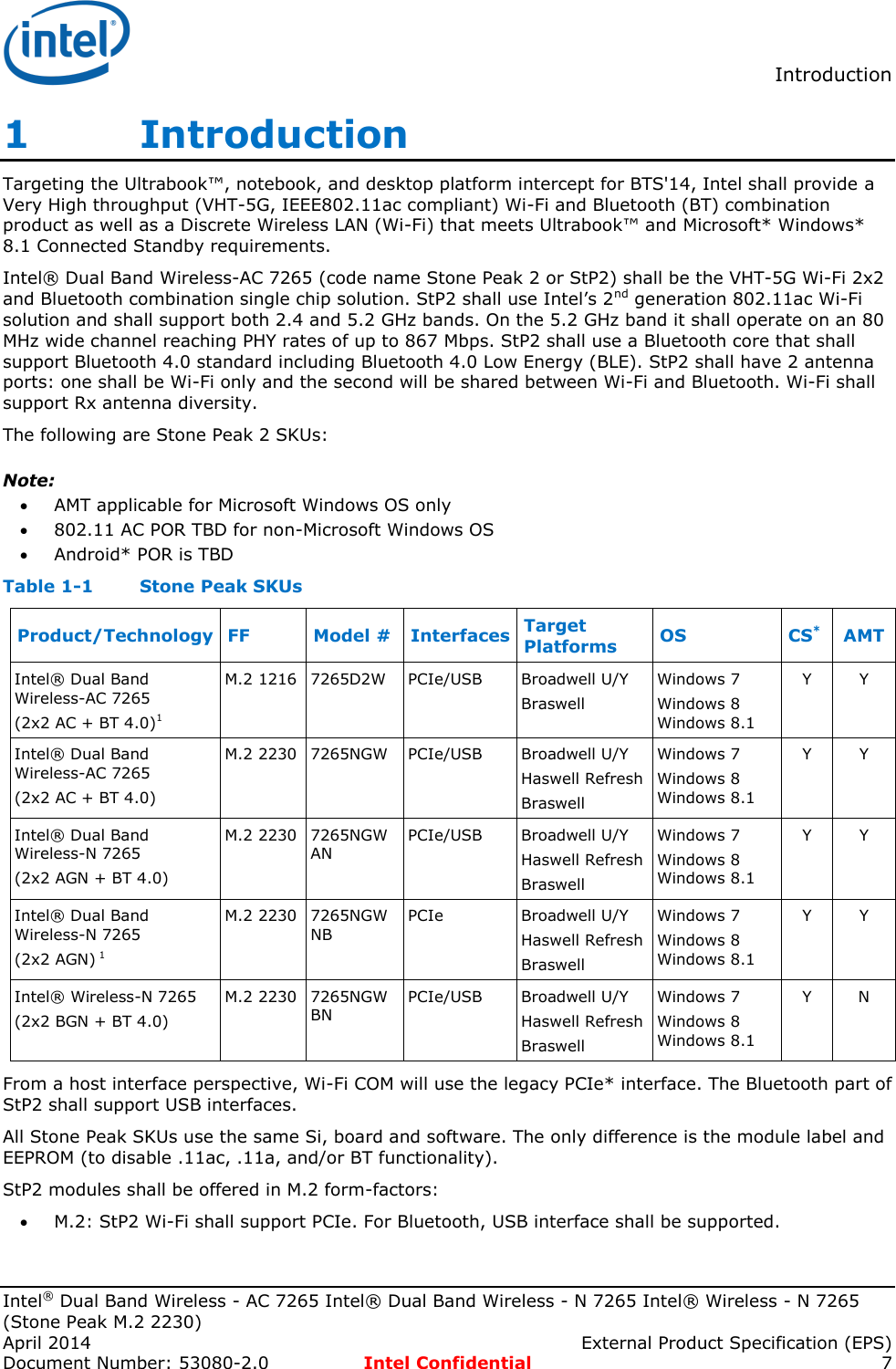
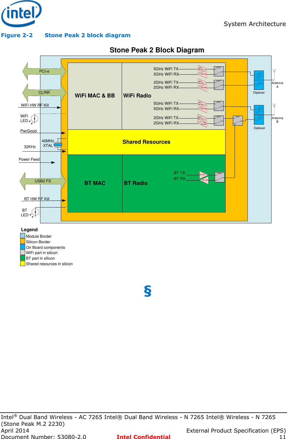
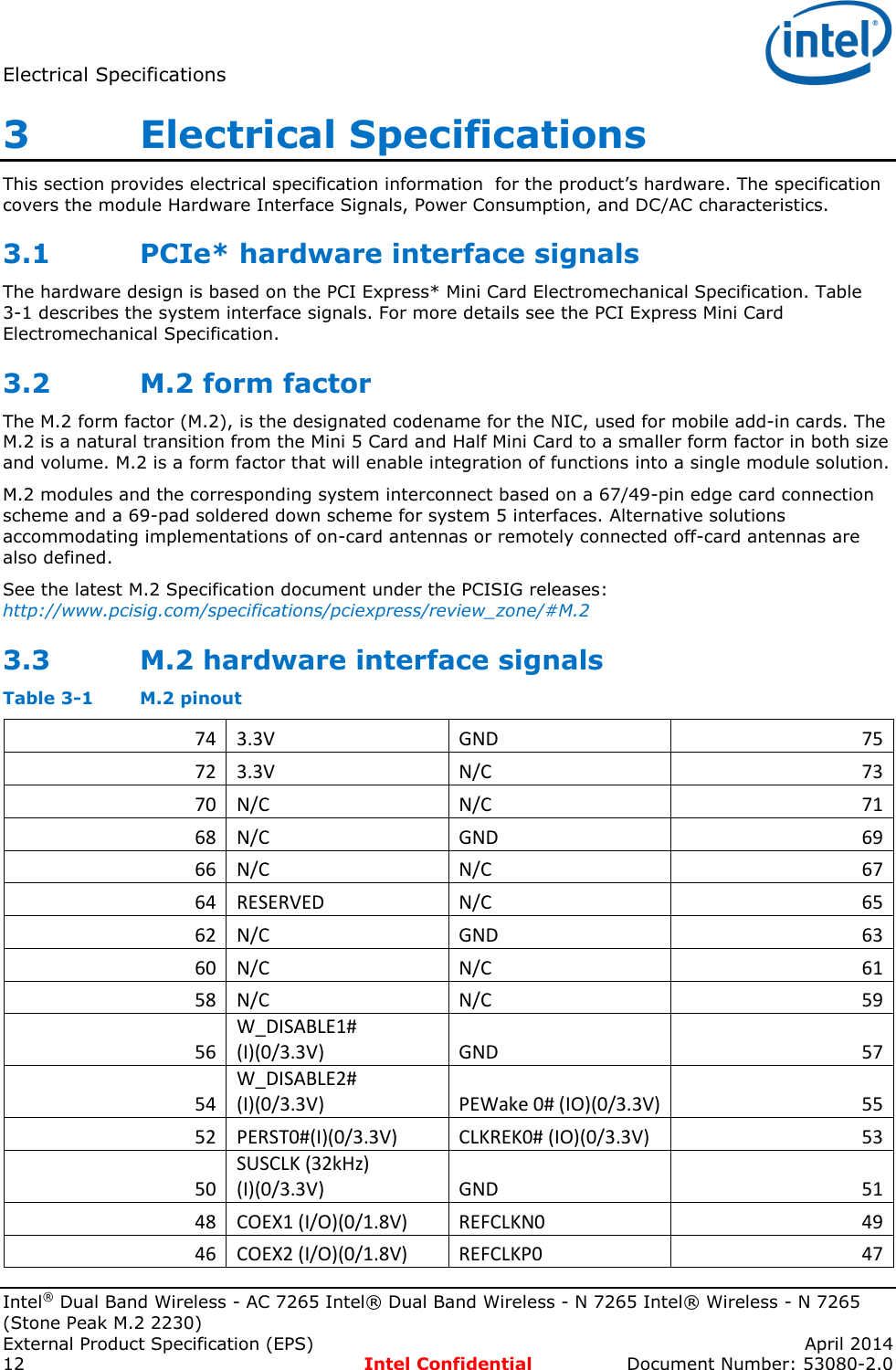
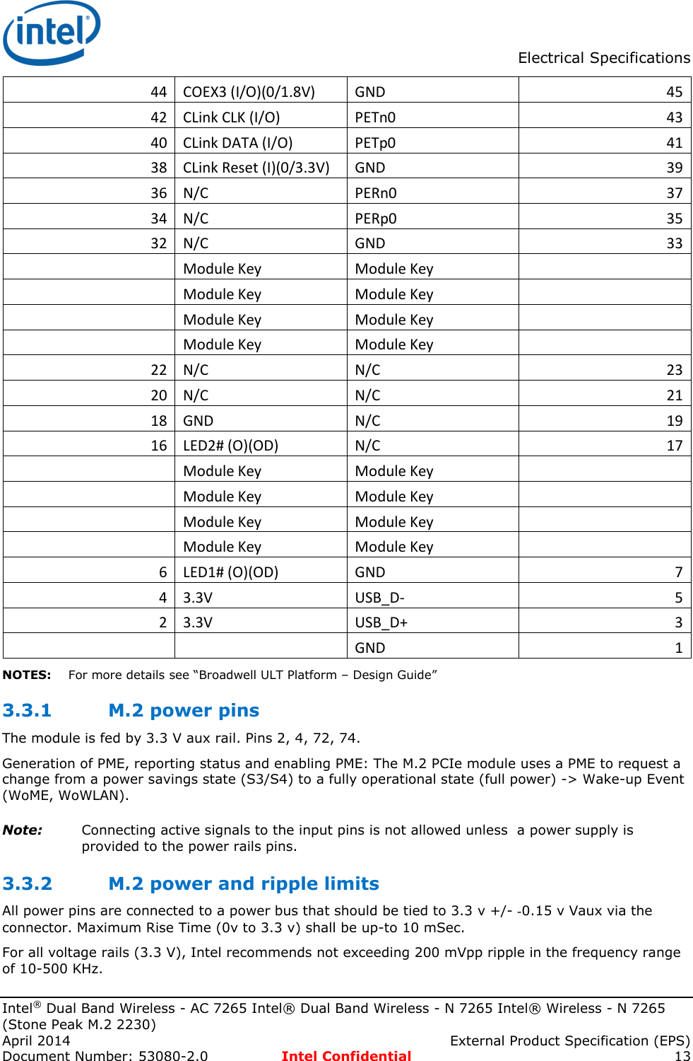
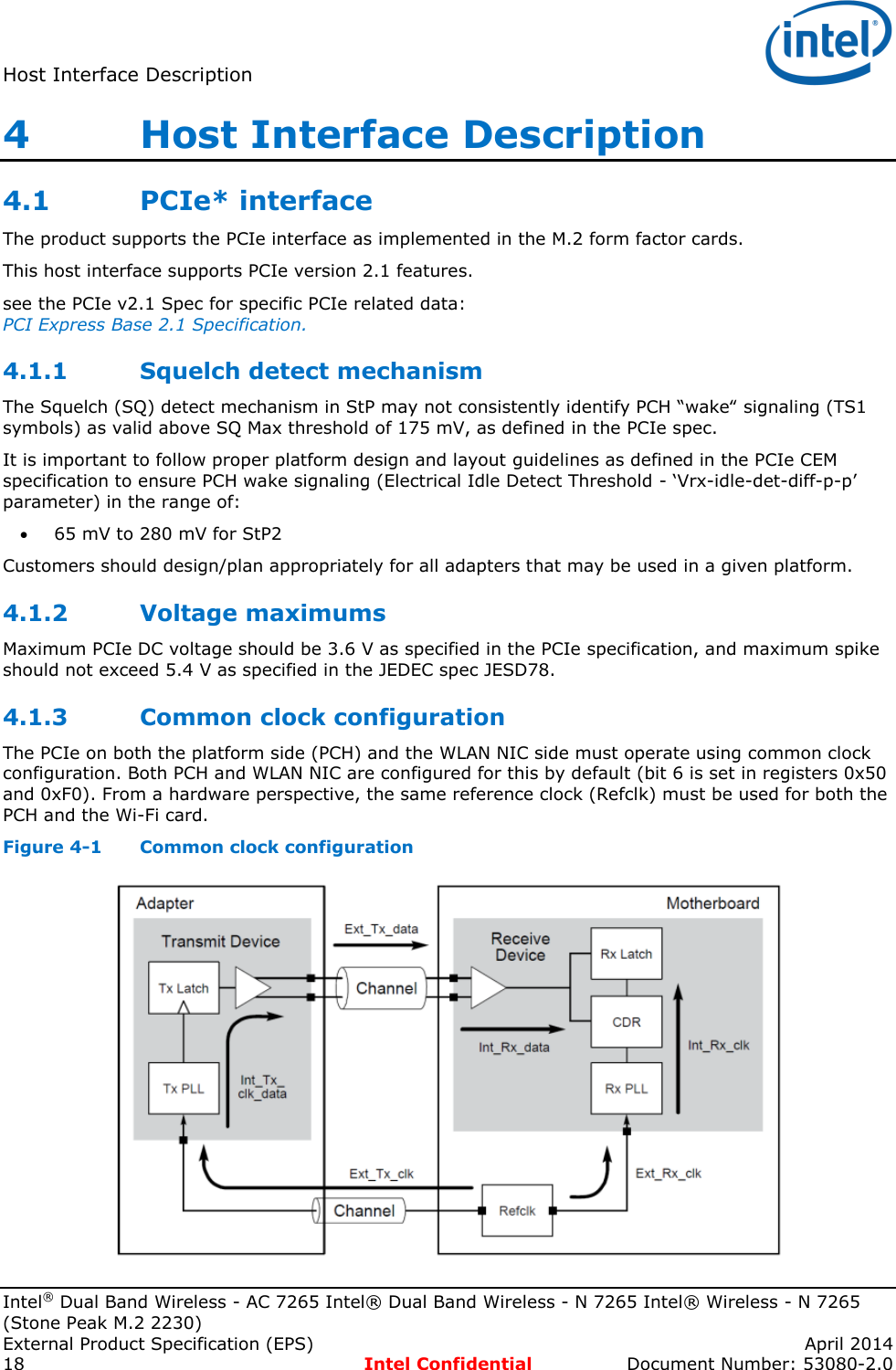
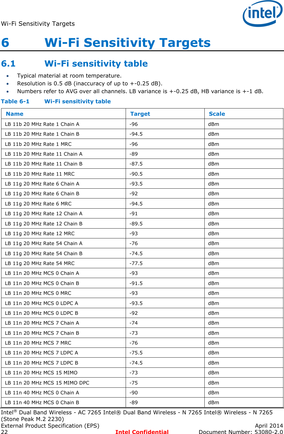
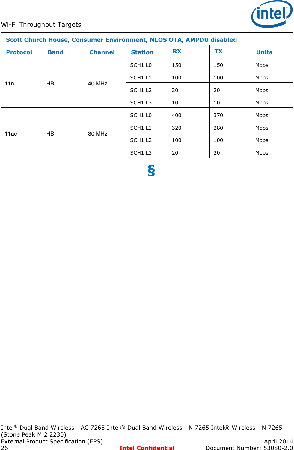
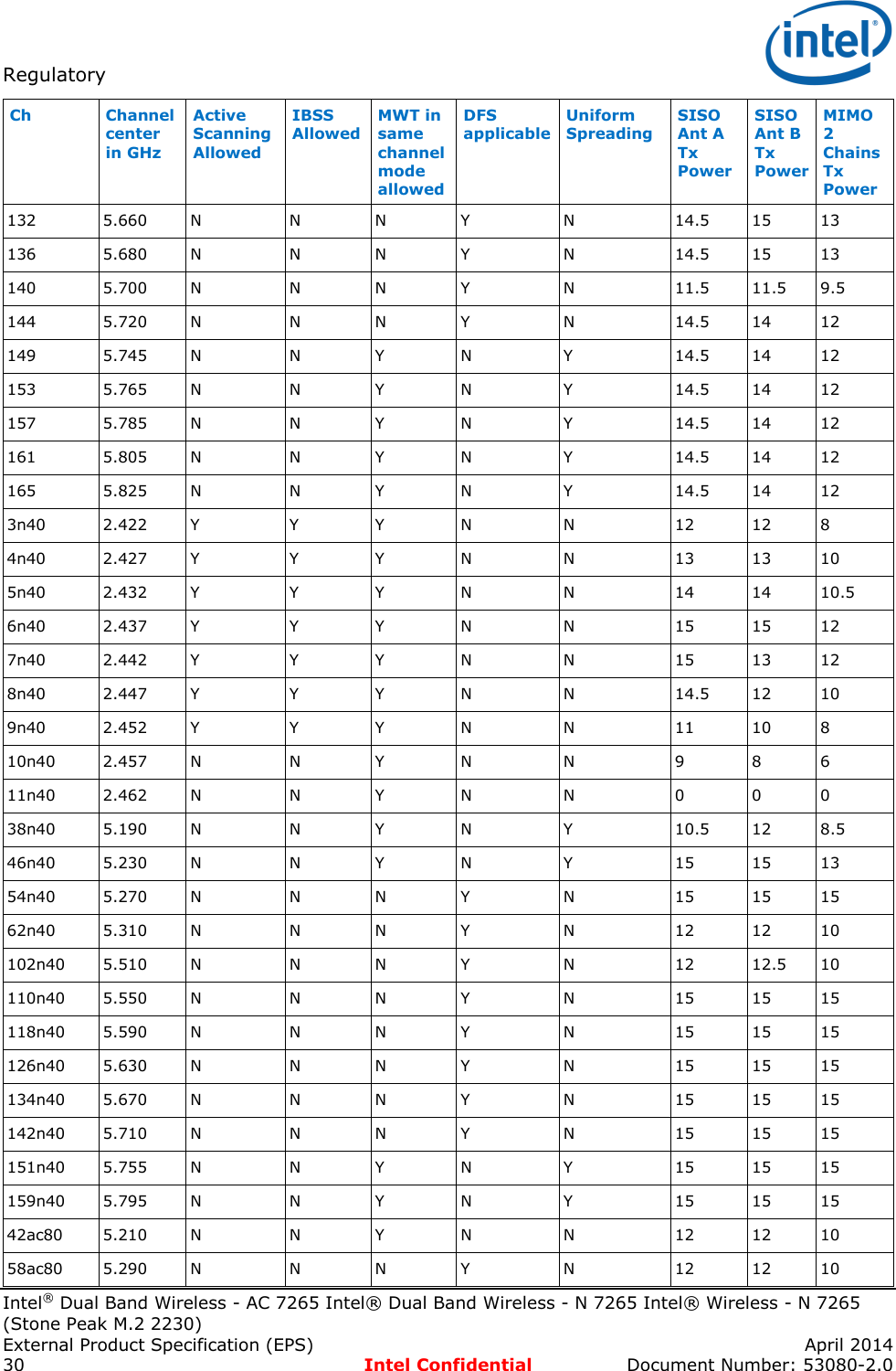
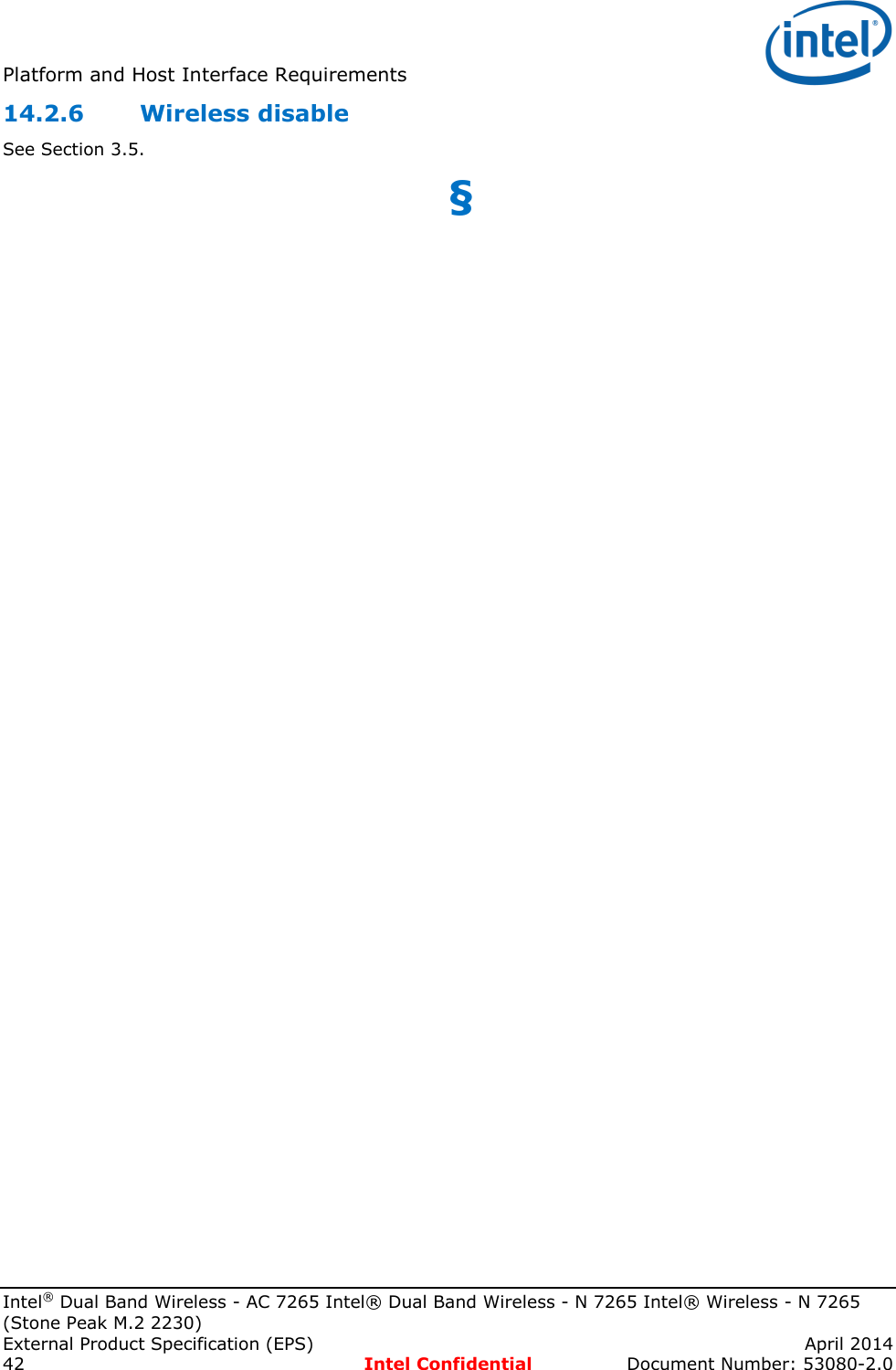
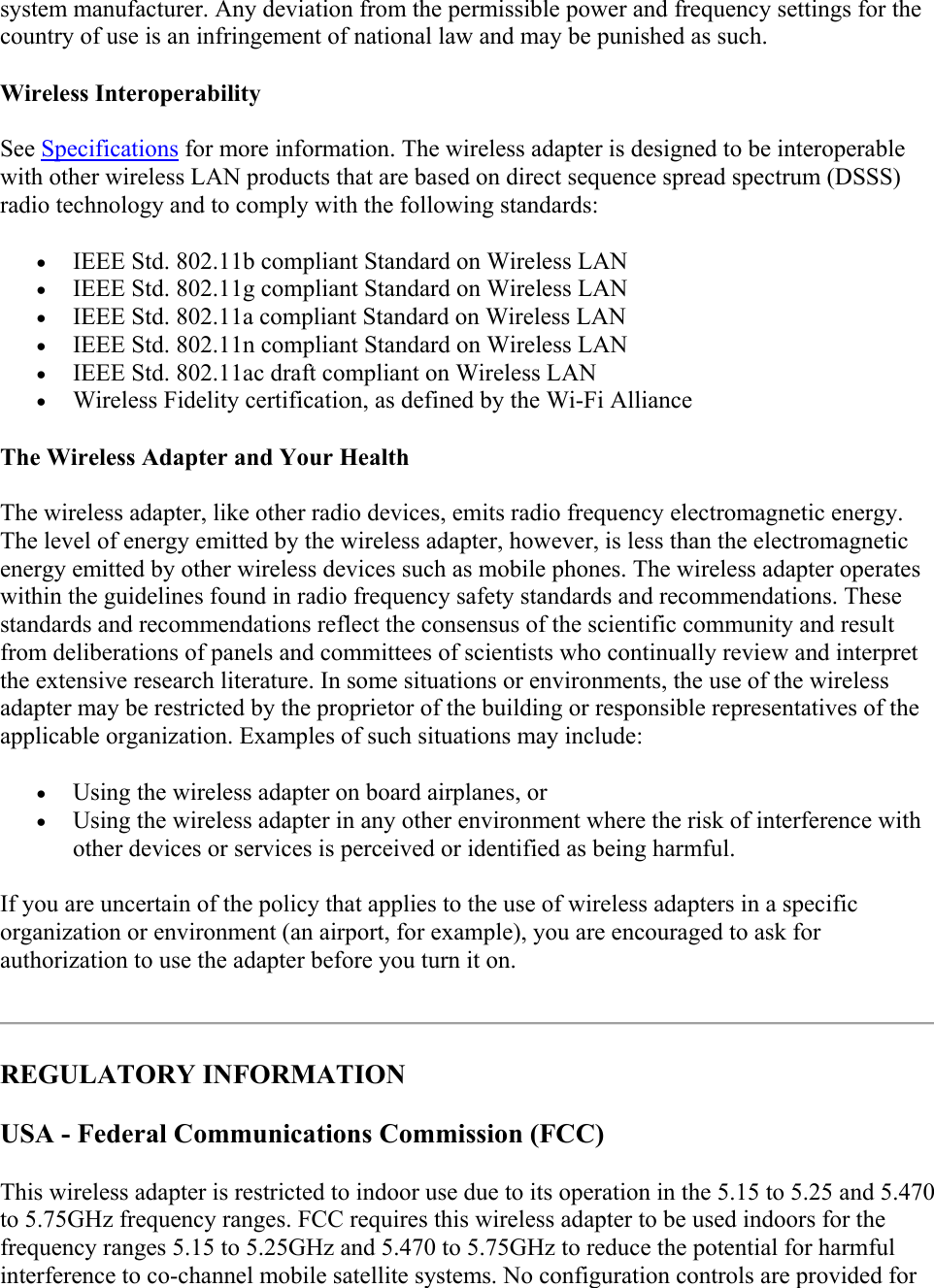
![Electrical Specifications Intel® Dual Band Wireless - AC 7265 Intel® Dual Band Wireless - N 7265 Intel® Wireless - N 7265 (Stone Peak M.2 2230) External Product Specification (EPS) April 2014 14 Intel Confidential Document Number: 53080-2.0 The card was tested under power rail noise up to 300 mVpp (10% of the nominal supply) w/o performance degradation. 3.3.3 Ground (GND) All ground pins are connected to a common ground bus that should be tied to system ground via the connector. 3.3.4 No BT SKUs For SKUs without BT: LED2#: NC W_DISABLE2#: Connect to GND USB_D-: NC USB_D+: NC 3.4 Module level power consumption 3.4.1 Power consumption definitions Module power consumption: 3.3 v rail power consumption. Note: Power consumption numbers define the total consumed power, including 3.3 v and 1.5 v power rails (the 1.5 v power rail is not in use.) Unless stated otherwise, power consumption refers to the highest average power consumption value over any 1-second period. Meter: measured using current probe loop on the power rails of the mini-card (or half mini-card interface/pins.) PCI-e ASPM (L1) and L1 sub states are enabled. (Note that L0s is not used.) Idle state assumes no scans. Scans will add ~15 mW to power consumption. Transmit output power is assumed to be 15 dBm. Platform is running on battery and power index is set to max power save (battery life.) Table 3-2 M.2 power consumption (mW) targets Test Benchmark Description Max Power [mW] WiFi + Bluetooth 1 Comms HW disabled HW RF kill All of the wireless devices on this card are disabled by HW RF-Kill. < 2 2 Comms SW disabled SW RF kill All of the wireless devices on this card are disabled by SW RF-Kill. (PCI at L1 Off / L2, USB at L2) < 2 3 Connected standby logo tests Wi-Fi is in connected standby (D0i3), low band, with no scan. Bluetooth core not paired (Windows OOB). <4 4 Windows idle associated, low band W-iFi is idle associated in low band. BT is running active A2DP profile (linked to stereo headset) but with no traffic. 16.5 5 Skype* video Wi-Fi is running Skype conference (2 people, SISO LB 20 MHz, 1.5 Mbps full duplex.) 160](https://usermanual.wiki/ASUSTeK-Computer/7265NG.7265NGW-UserMan/User-Guide-2421853-Page-14.png)
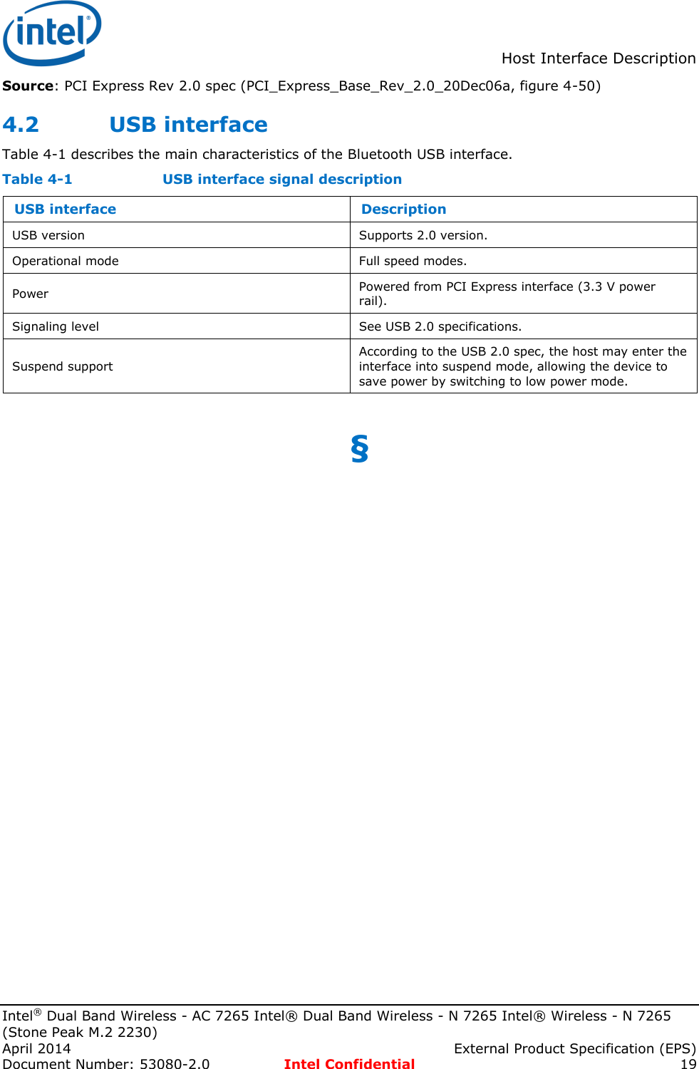
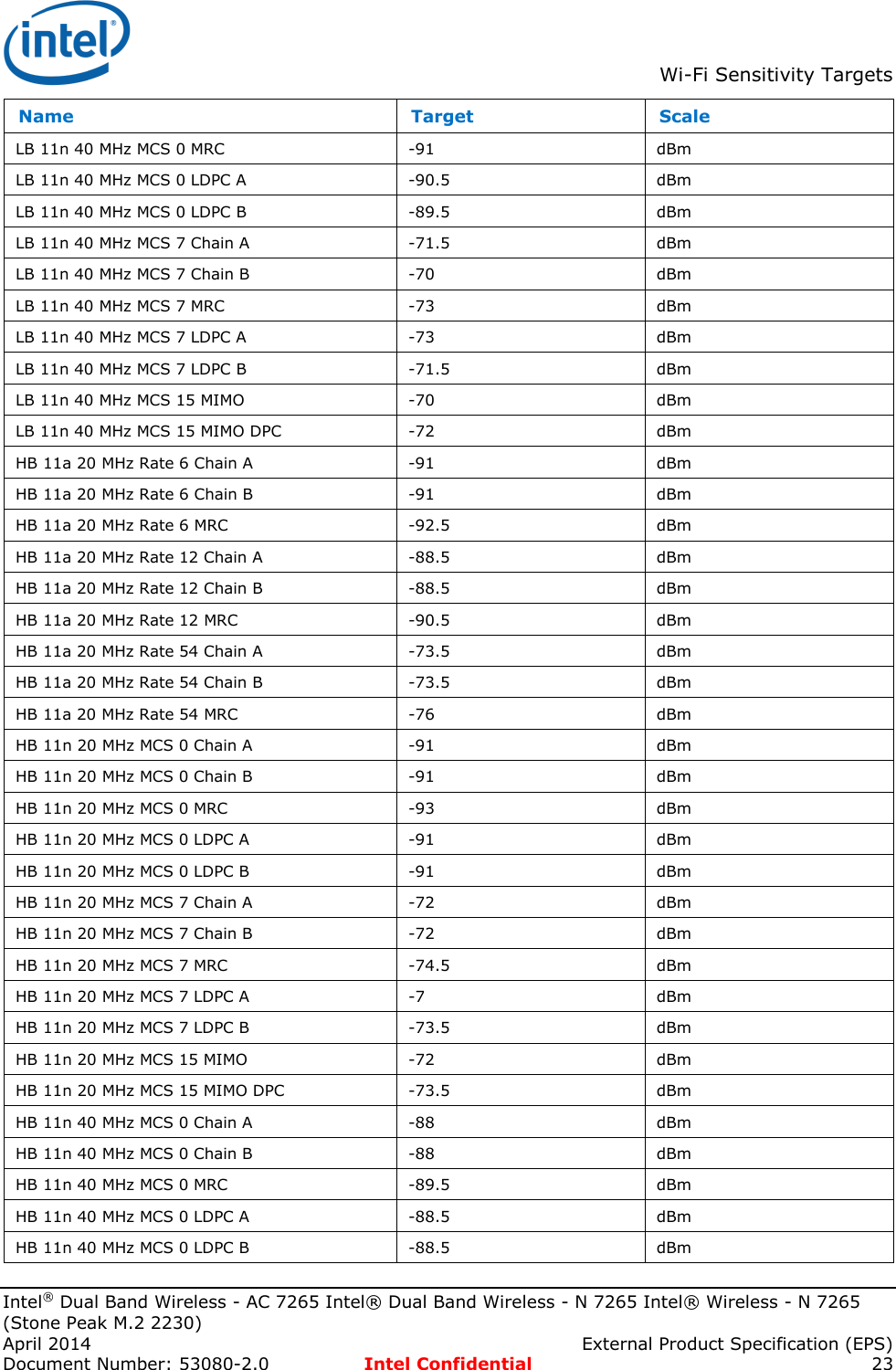
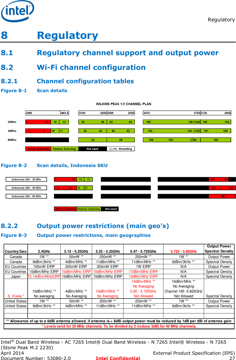
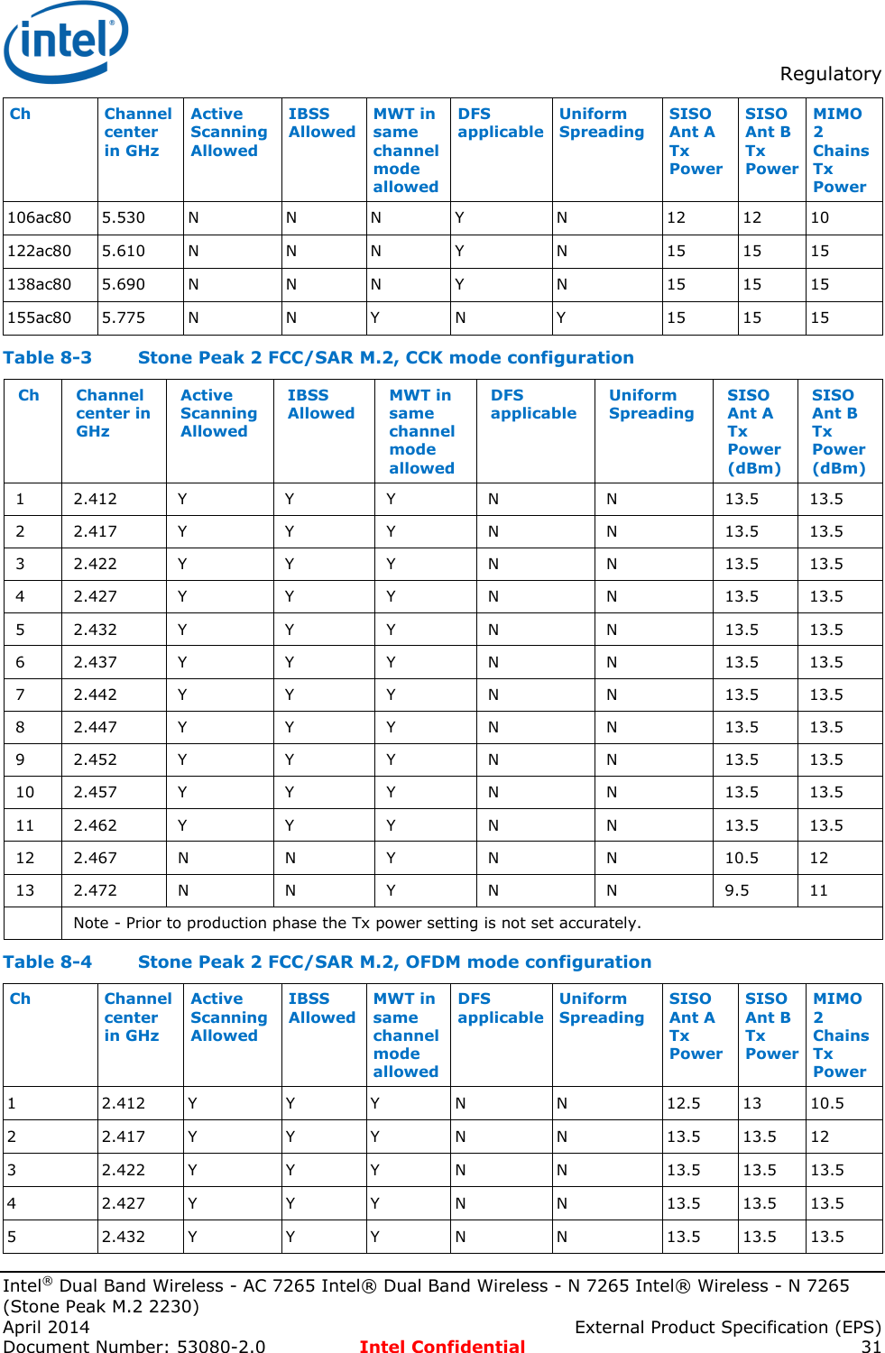
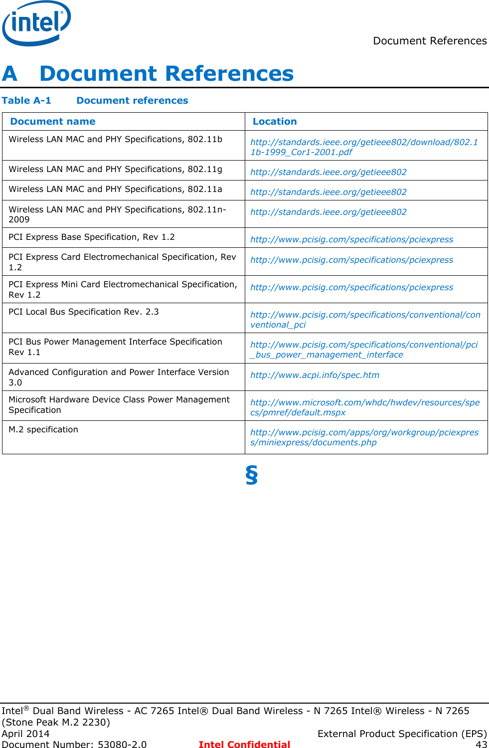
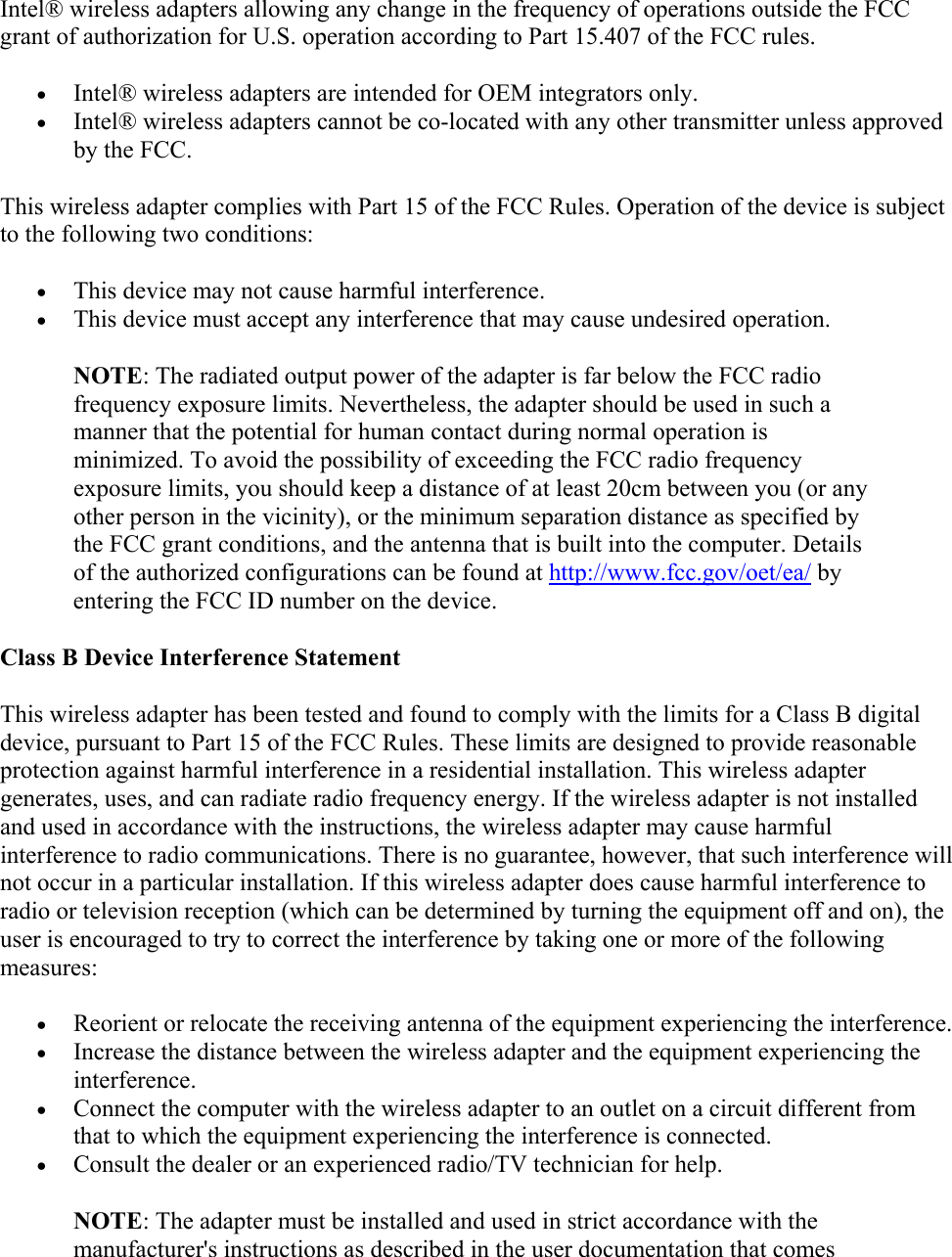
![Electrical Specifications Intel® Dual Band Wireless - AC 7265 Intel® Dual Band Wireless - N 7265 Intel® Wireless - N 7265 (Stone Peak M.2 2230) April 2014 External Product Specification (EPS) Document Number: 53080-2.0 Intel Confidential 15 Test Benchmark Description Max Power [mW] WiFi + Bluetooth conferencing Bluetooth paired with HFP (audio eSCO S2/S3.) 6 Video streaming (LB) Wi-Fi is running unidirectional Rx, 720/1080p @ 30fps (8 mbps) on low band. Bluetooth paired with A2DP @ 345 kbps. 385 7 WiDi DCM scenario Laptop is streaming WiDi content (max resolution) – 12 Mbps. Wi-Fi BSS client on LB, WiDi on HB (40 MHz channel.) BT is connected to a mouse (HID) 290 8 Comms excursion (modeled) Wi-Fi - 802.11n link at 200 mbps, FTP transmitting 90% and FTP receiving 10%. Bluetooth - A2DP, 375 Kbps (Tx). <1440 The modules are implemented according to the ACPI v3.0 Specification, supporting the peripheral power states D0 and D3 as listed in Table 3-3. D3 hot means D3 with PERST# high (de-asserted) and power on. D3 cold means D3 with PERST# low (asserted) and auxiliary power on. Table 3-3 Supported D-states Device power states Description D0 (Uninitiated and Active) Supported D3 (hot and cold) Supported for PCIe 3.4.2 Enabling Ethernet controllers with ASPM ASPM defines the “L” states of the PCIe connections, L0, L0s, L1 and L2; among all those states, L0s has very low power saving vs. high complexity and risk. As a result the StP w/Bluetooth hardware devices shall not support PCI Express* ASPM L0s power state, and shall support the L1 state that has high value as a power saving state. StP supports ASPM optionality ECN, allowing support of L1 without L0s. No special BIOS actions are required. 3.4.3 Intel® Power Optimizer With the Broadwell platform Intel has introduced new initiatives to significantly reduce platform power consumption. The Intel Power Optimizer is a power management framework that allows for usage of deep, long latency platform power management states through new bus extensions. Table 3-4 Stone Peak 2 family Intel® Power Optimizer capability Family Technology Form Factor Interface LTR RTD31 L1 States (L1.1, L1.2) 7265.NGWG 2x2 AC + BT M.2 PCIe/USB Yes Yes Yes 7265.NGWANG 2X2 AGN + BT M.2 PCIe/USB Yes Yes Yes 7265.NGWNBG 2X2 AGN (No BT) M.2 PCIe Yes Yes Yes 7265.NGWBNG 2x2 BGN + BT M.2 PCIe/USB Yes Yes Yes NOTES: 1. Connected standby systems only.](https://usermanual.wiki/ASUSTeK-Computer/7265NG.7265NGW-UserMan/User-Guide-2421853-Page-15.png)
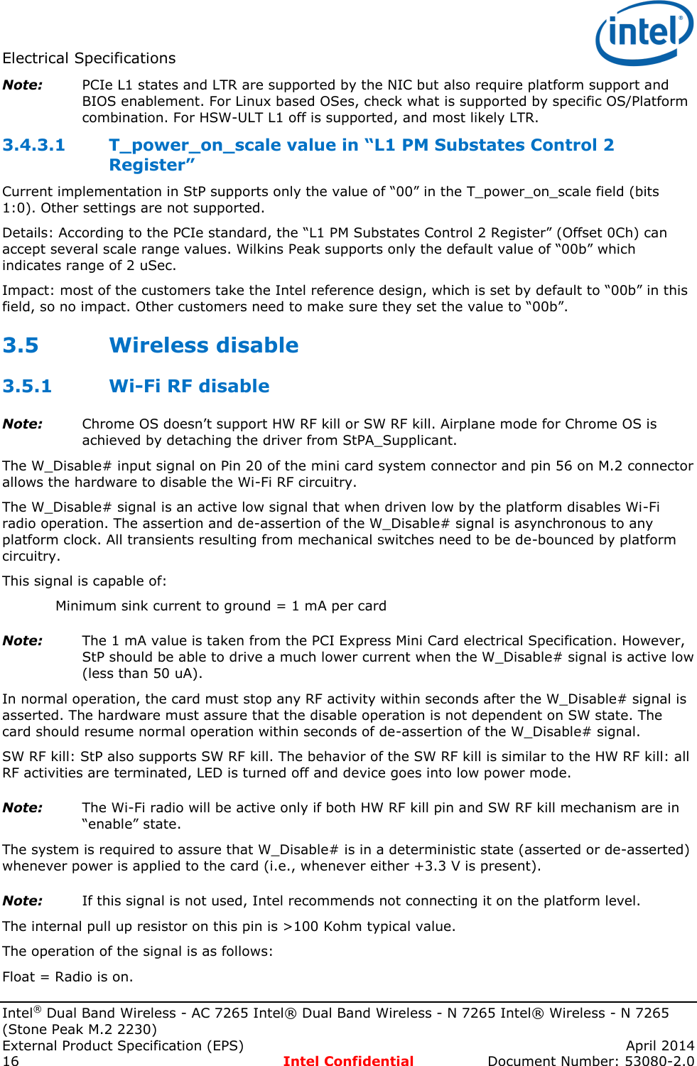
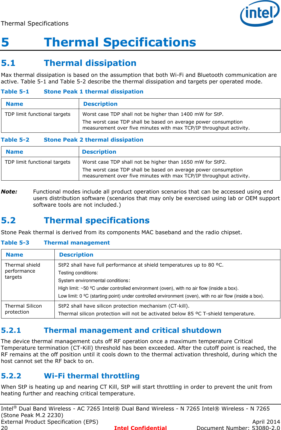
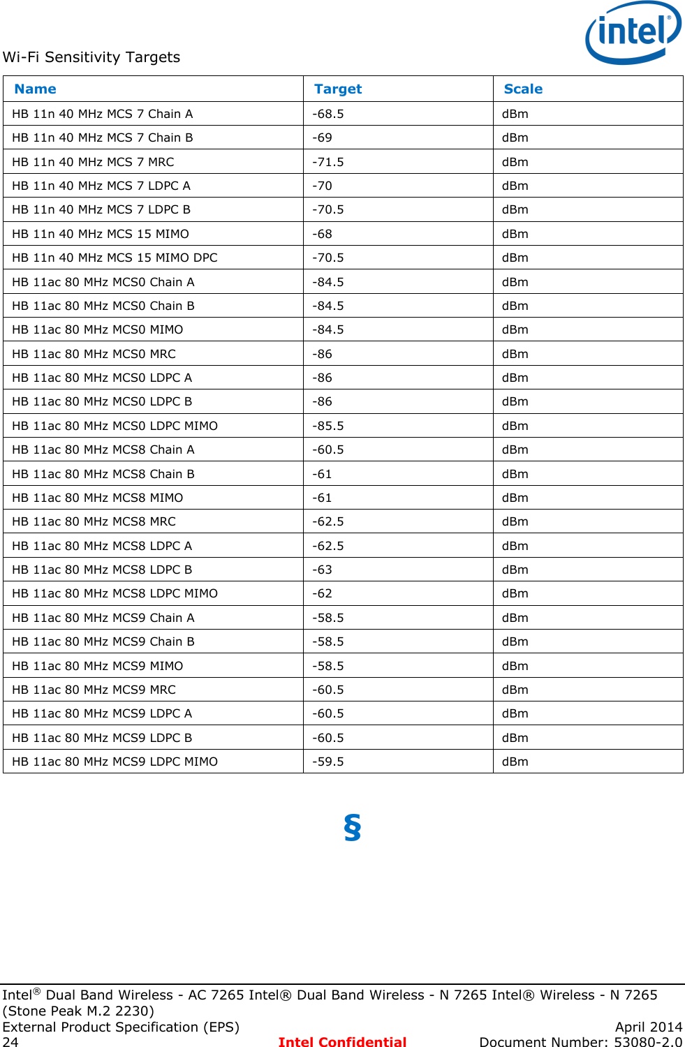
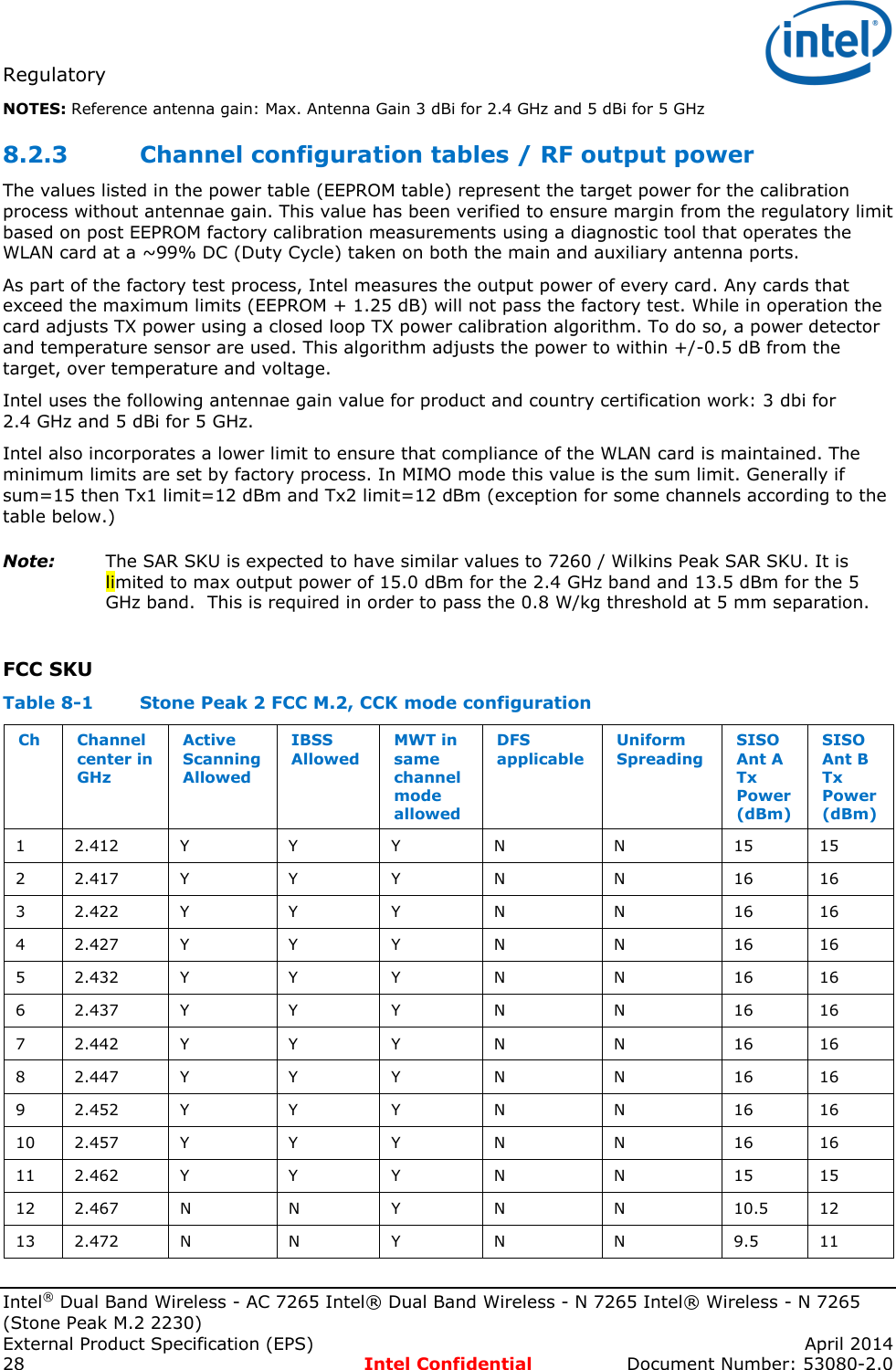
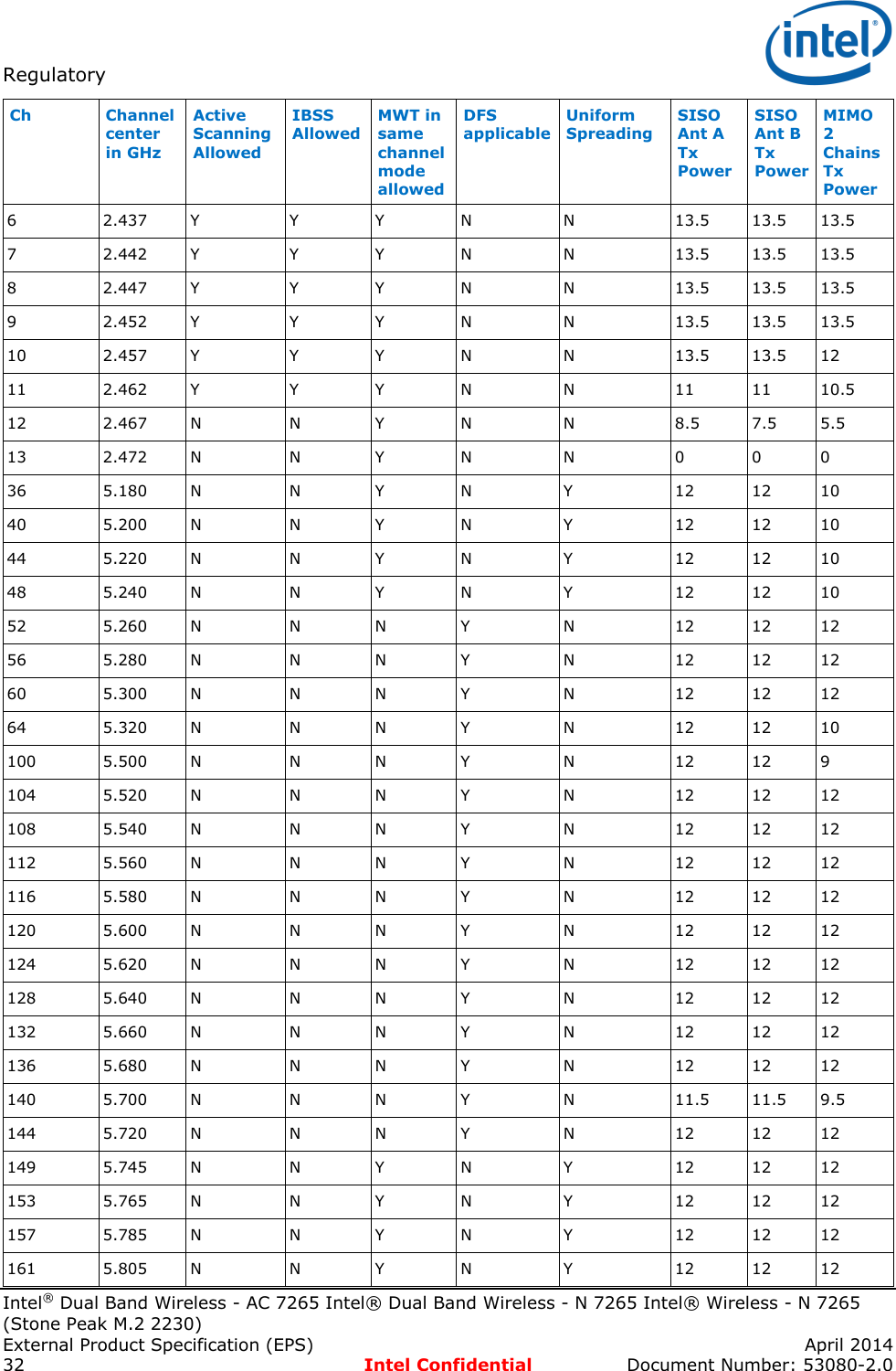
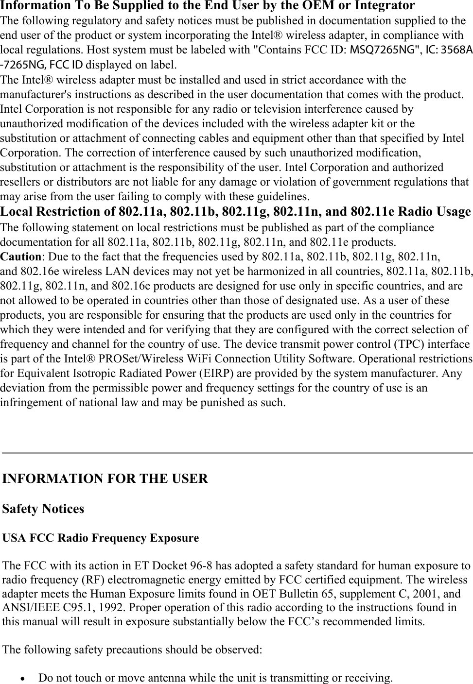
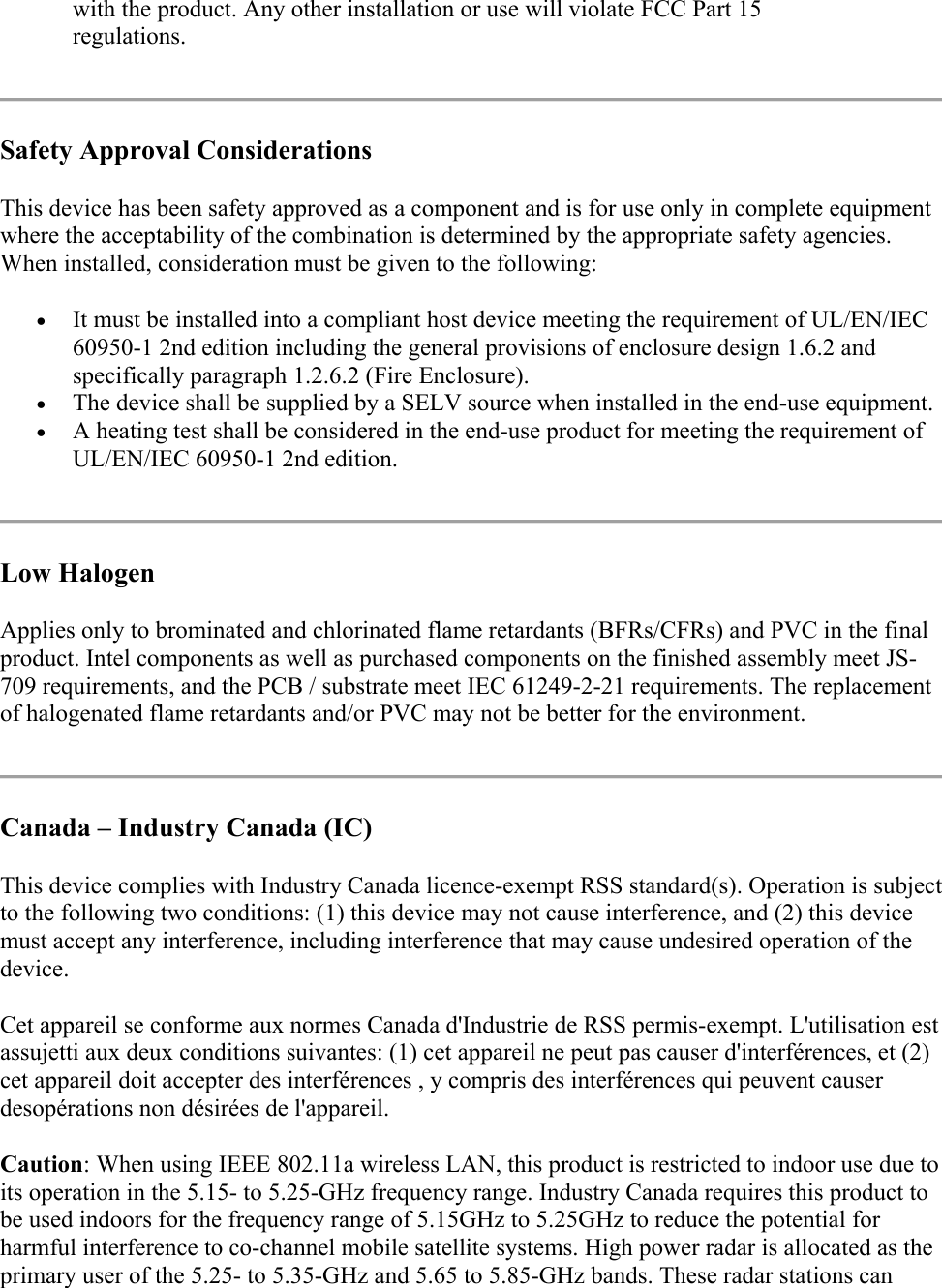
![Electrical Specifications Intel® Dual Band Wireless - AC 7265 Intel® Dual Band Wireless - N 7265 Intel® Wireless - N 7265 (Stone Peak M.2 2230) April 2014 External Product Specification (EPS) Document Number: 53080-2.0 Intel Confidential 17 Off (Active low: Vil = 0.0 v [+/-0.3]) = Radio transmitter is turned off and incapable of transmitting. Table 3-5 Hardware RF disable logic Software setting Hardware switch Radio transmitter function Enabled Enabled/float Enabled Enabled Disabled/low Disabled Disabled Enabled/float Disabled Disabled Disabled/low Disabled 3.5.2 Bluetooth RF disable M.2 Bluetooth hardware RF disable 3.5.2.1W_DISABLE#_2 (pin 54) is the HW RF kill for the Bluetooth radio. Asserting W_DISABLE#_2 signal will result in a complete shutdown of the Bluetooth part. The result from the user perspective is similar to removing the Bluetooth device from the laptop. The W_DISABLE#_2 internal pull up resistor is ~130 Kohm typical value. 3.5.3 Bluetooth software RF disable StP also supports Bluetooth SW RF kill. The behavior of the SW RF kill is similar to the HW RF kill: all RF activities are terminated, LED is turned off and device goes into low power mode. Note: The BT radio will be active only if both HW RF kill pin and SW RF kill mechanism are in “enable” state. Note: RF kill not supported with Chrome OS. 3.6 LED indicators StP2 products have 2 LEDs signals each: A Bluetooth LED, and a Wi-Fi LED. Bluetooth LED functionality: 1. LED is OFF when the Bluetooth is in HW or SW RF kill (SW RF kill means also driver disable, etc.). 2. LED is ON otherwise. Wi-Fi LED functionality: 1. LED is OFF when the Wi-Fi is not powered or in RF kill. 2. LED is ON otherwise. Note: Chrome OS doesn’t support or require LED for comms. Hence the LED signals should remain disconnected. Note: The LED output pins (for both Wi-Fi and Bluetooth) are not open drain pins. Therefore, it is not allowed to Wire-Or the two LED pins and connect them to a single LED without glue logic. This is applicable to both StP and Wilkins Peak. §](https://usermanual.wiki/ASUSTeK-Computer/7265NG.7265NGW-UserMan/User-Guide-2421853-Page-17.png)