ASUSTeK Computer B2200BG NOTEBOOK P.C. User Manual NB Copyright Eng 3 4 03 p65
ASUSTeK Computer Inc NOTEBOOK P.C. NB Copyright Eng 3 4 03 p65
UserManual.wiki
>
ASUSTeK Computer
>
B2200BG User Manual
USERS MANUAL
Navigation menu
Upload a User Manual
Namespaces
Wiki Guide
HTML
PDF
Info
Views
User Manual
Discussion / Help
Navigation


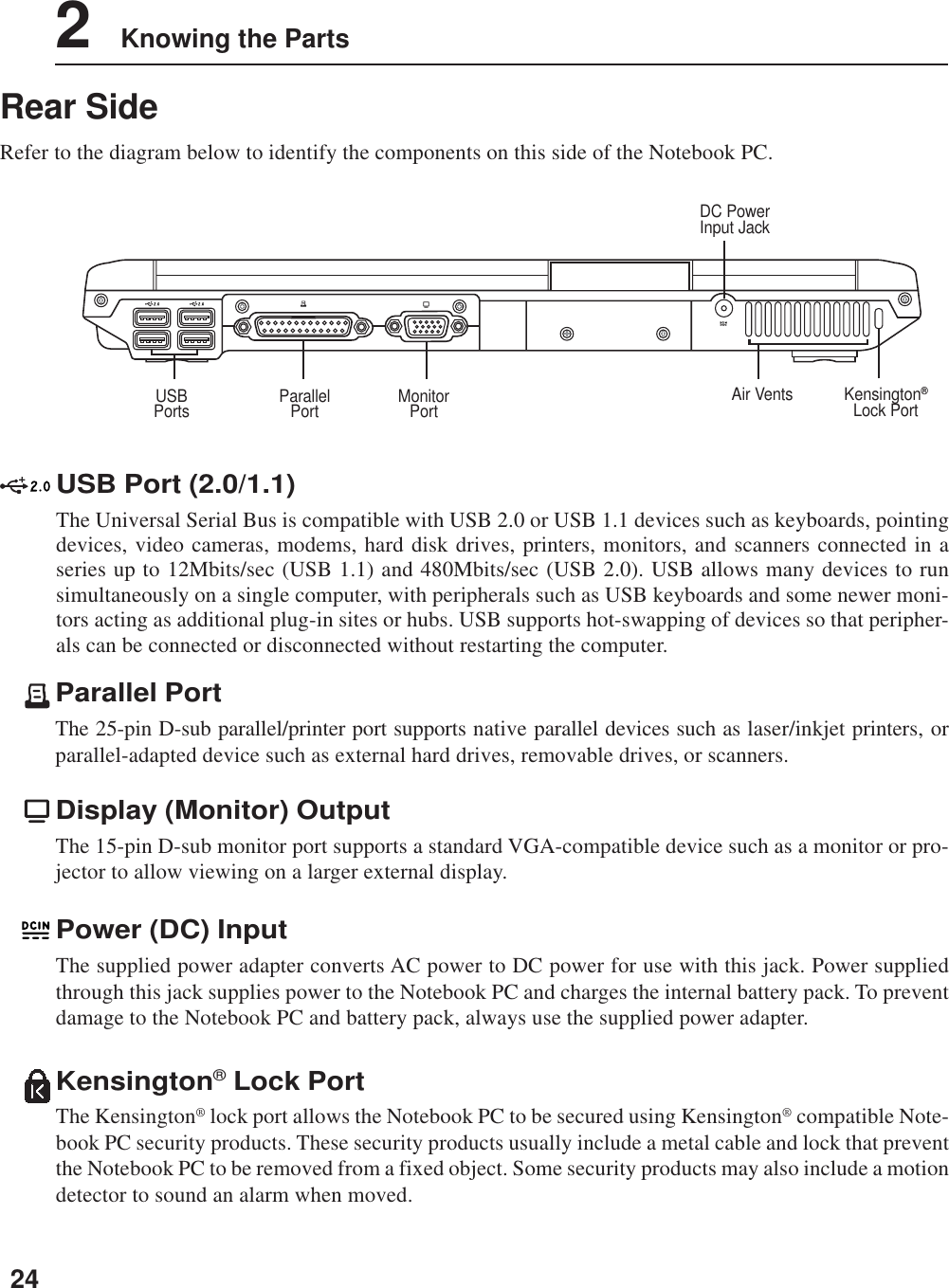
![121 Introducing the Notebook PCAbout This User’s ManualYou are reading the Notebook PC User’s Manual. This User’s Manual provides information on thevarious components in the Notebook PC and how to use them. The following are major sections of thisUser’s Manuals:1. Introducing the Notebook PCIntroduces you to the Notebook PC and this User’s Manual.2. Knowing the PartsGives you information on the Notebook PC’s components.3. Getting StartedGives you information on getting started with the Notebook PC.4. Using the Notebook PCGives you information on using the Notebook PC’s components.5. AppendixIntroduces you to optional accessories and gives additional information.Notes For This ManualThis User’s Manual was created using Macintosh versions of Adobe® PageMaker™ 6.52, Adobe®Photoshop™ 5.5, Adobe® Illustrator® 8.0, and Macromedia® Freehand™ 8.0.1. The body text type usedin this manual is “Times” (MAC) or “Times New Roman” (Windows™) and headings are “Helvetica”(MAC) or “Arial” (Windows™). A few notes and warnings in bold are used throughout this guide thatyou should be aware of in order to complete certain tasks safely and completely. These notes havedifferent degrees of importance as described below:NOTE: Tips and information for spe-cial situations.TIP: Tips and useful information forcompleting tasks.Text enclosed in < > or [ ] represents a key on the keyboard; do not actually type the <> or [ ] and the enclosed letters.< >[ ]WARNING! Important information thatmust be followed for safe operation.IMPORTANT! Vital information thatmust be followed to prevent damageto data, components, or persons.](https://usermanual.wiki/ASUSTeK-Computer/B2200BG/User-Guide-440585-Page-14.png)
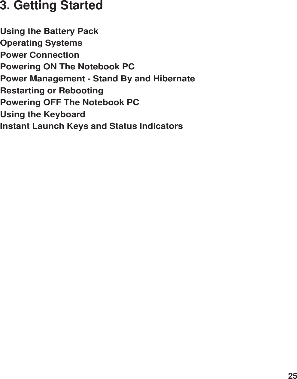
![13Introducing the Notebook PC 1Preparing your Notebook PCThese are only quick instructions for using your Notebook PC. Read the later pages for detailed infor-mation on using your Notebook PC.1. Install the battery pack3. Open the Display Panel 4. Turn ON the Notebook PC2. Connect the AC Power AdapterPress the power button and release.In Windows XP, this button can also be used tosafely turn OFF the Notebook PC.(1) Slide the display release button(2) Lift the display panel with one hand whileholding the system portion with your otherhand.[1][2]1221](https://usermanual.wiki/ASUSTeK-Computer/B2200BG/User-Guide-440585-Page-15.png)


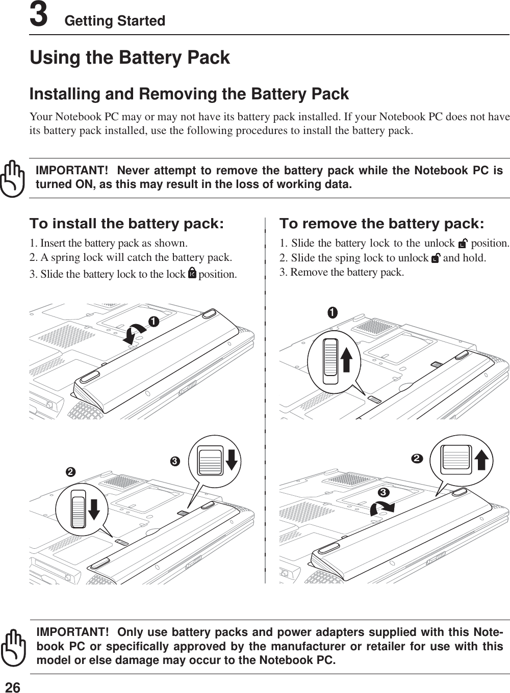
![283 Getting StartedNOTE: This Notebook PC may come with either a two or three-prong plug dependingon territory. If a three-prong plug is provided, you must use a grounded AC outlet oruse a properly grounded adapter to ensure safe operation of the Notebook PC.With the AC power cord connected to the AC-DC converter, connect the AC power cord to an AC outlet(preferably with surge-protection) and then connect the DC plug to the Notebook PC. Connecting theAC-DC adapter to the AC outlet first allows you to test the AC outlet’s power and the AC-DC converteritself for compatibility problems before connecting the DC power to the Notebook PC. The greenpower LED on the adapter lights up if the power is within accepted ranges.TIP: You can buy travel kits for the Notebook PC that includes power and modemadapters for almost every country.IMPORTANT! Damage may occur if you use a different adapter to power the Note-book PC or use the Notebook PC’s adapter to power other electrical devices. If thereis smoke, burning scent, or extreme heat coming from the AC-DC adapter, seek ser-vicing. Seek servicing if you suspect a faulty AC-DC adapter. You may damage bothyour battery pack(s) and the Notebook PC with a faulty AC-DC adapter.[1][2]Power ConnectionYour Notebook PC comes with a universal AC-DC adapter. That means that you may connect thepower cord to any 100V-120V as well as 220V-240V outlets without setting switches or using powerconverters. Different countries may require that an adapter be used to connect the provided US-stan-dard AC power cord to a different standard. Most hotels will provide universal outlets to support differ-ent power cords as well as voltages. It is always best to ask an experienced traveler about AC outletvoltages when bringing power adapters to another country.](https://usermanual.wiki/ASUSTeK-Computer/B2200BG/User-Guide-440585-Page-30.png)
![29Getting Started 3The Power-On Self Test (POST)When you turn ON the Notebook PC, it will first run through a series of software-controlled diagnostictests called the Power-On Self Test (POST). The software that controls the POST is installed as apermanent part of the Notebook PC’s architecture. The POST includes a record of the Notebook PC’shardware configuration, which is used to make a diagnostic check of the system. This record is createdby using the BIOS Setup program. If the POST discovers a difference between the record and theexisting hardware, it will display a message on the screen prompting you to correct the conflict byrunning BIOS Setup. In most cases the record should be correct when you receive the Notebook PC.When the test is finished, you may get a message reporting “No operating system found” if the harddisk was not preloaded with an operating system. This indicates that the hard disk is correctly detectedand ready for the installation of a new operating system.The S.M.A.R.T. (Self Monitoring and Reporting Technology) checks the hard disk drive during POSTand gives a warning message if the hard disk drive requires servicing. If any critical hard disk drivewarning is given during bootup, backup your data immediately and run Windows disk checking program.To run Window’s disk checking program: (1) right-click any hard disk drive icon in “My Computer”, (2)choose Properties, (3) click the Tools tab, (4) click Check Now, (5) select a hard disk drive, (6) selectThorough to also check for physical damages, and (7) click Start. Third party disk utilities such as Symantec’sNorton Disk Doctor can also perform the same functions but with greater ease and more features.Powering ON The Notebook PCThe Notebook PC’s power-ON message appears on the screen when you turn it ON. If necessary, you mayadjust the brightness by using the hot keys. If you need to run the BIOS Setup to set or modify the systemconfiguration, press [F2] upon bootup to enter the BIOS Setup. If you press [Tab] during the splashscreen, standard boot information such as the BIOS version can be seen. Press [ESC] and you will bepresented with a boot menu with selections to boot from your available drives.NOTE: Before bootup, the display panel flashes when the power is turned ON. This ispart of the Notebook PC’s test routine and is not a problem with the display.IMPORTANT! If warnings are still given during bootup after running a software diskchecking utility, you should take your Notebook PC in for servicing. Continued usemay result in data loss.IMPORTANT! Never turn OFF or reset your Notebook PC while the hard disk or floppydisk is in use and the activity LED is flashing; doing so can result in loss or destruc-tion of your data. To protect the hard disk drive, always wait at least 5 seconds afterturning OFF your Notebook PC before turning it back ON.](https://usermanual.wiki/ASUSTeK-Computer/B2200BG/User-Guide-440585-Page-31.png)
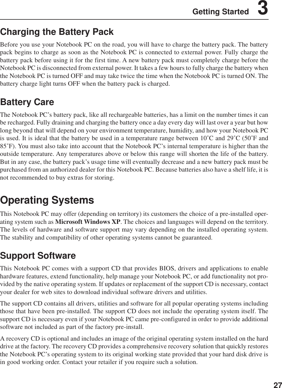
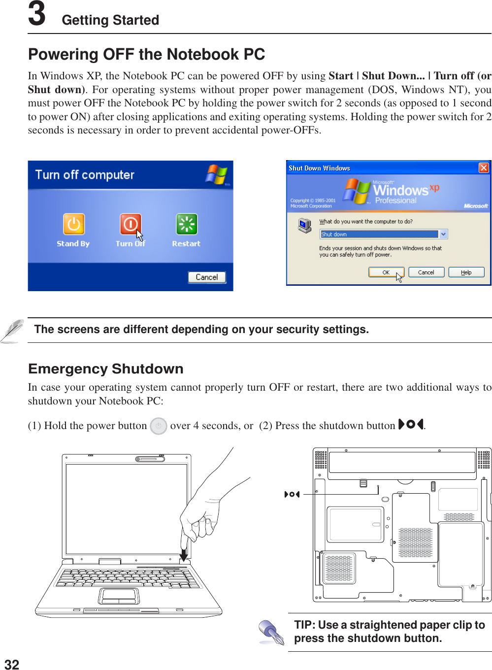
![31Getting Started 3Restarting or RebootingAfter making changes to your operating system, you may be prompted to restart the system. Someinstallation processes will provide a dialog box to allow restart. To restart the system manually:Click the Start button and select Shut Down | and choose Restart.In case the operating system hangs (stops, freezes, crashes), try a “warm boot” by pressing [Ctrl][Alt][Del]keys simultaneously. (You may try a few times if there is no response.)The screens are different depending on your security settings.](https://usermanual.wiki/ASUSTeK-Computer/B2200BG/User-Guide-440585-Page-33.png)
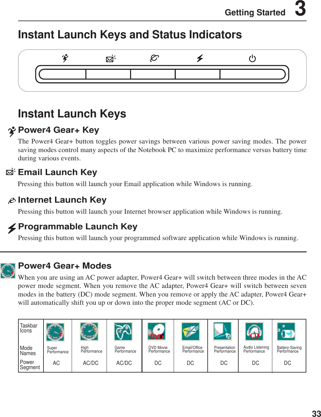
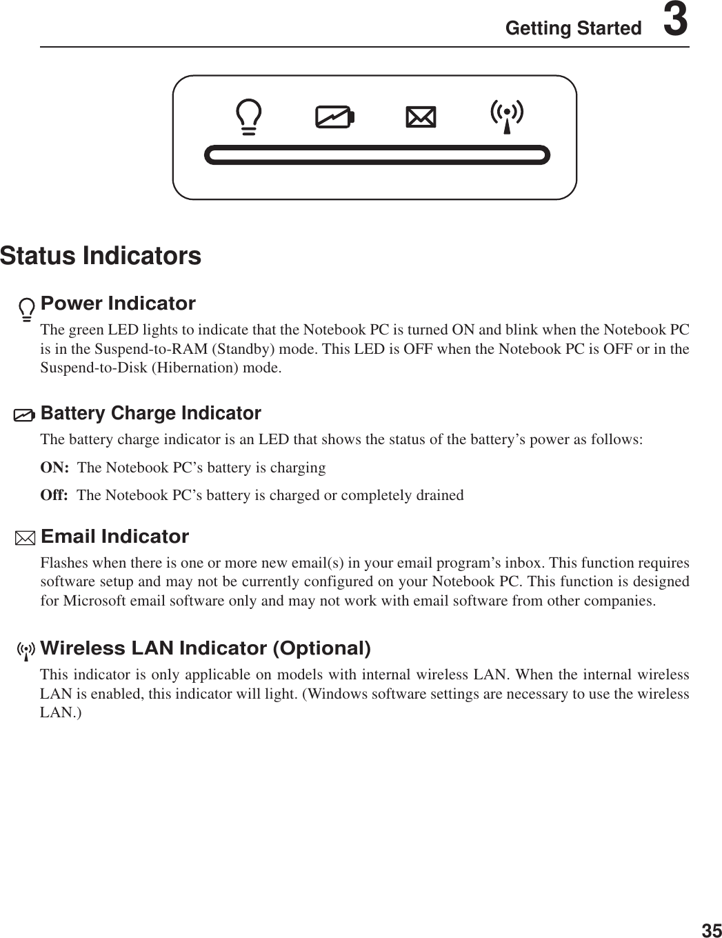
![343 Getting StartedStatus IndicatorsDrive Activity IndicatorIndicates that the Notebook PC is accessing one or more storage device(s) such as the hard disk. Thelight flashes proportional to the access time.Number LockIndicates that number lock [Num Lk] is activated when lighted. Number lock allows some of the key-board letters to act as numbers for easier numeric data input.Capital LockIndicates that capital lock [Caps Lock] is activated when lighted. Capital lock allows some of thekeyboard letters to type using capitalized letters (e.g. A, B, C). When the capital lock light is OFF, thetyped letters will be in the lower case form (e.g. a,b,c).Scroll LockIndicates that scroll lock [Scr Lk] is activated when lit. Scroll lock allows some of the keyboard lettersto act as direction keys in order to allow easier navigation when only a part of the keyboard is required,such as for playing games.](https://usermanual.wiki/ASUSTeK-Computer/B2200BG/User-Guide-440585-Page-36.png)
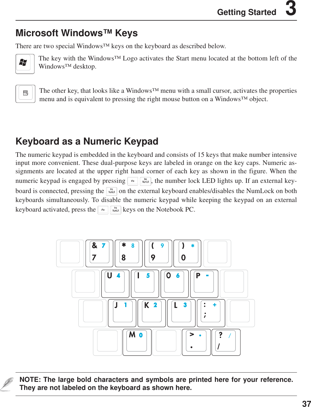
![383 Getting StartedKeyboard as CursorsThe keyboard can be used as cursors while Number Lock is ON or OFF in order to increase navigationease while entering numeric data in spreadsheets or similar applications.With Number Lock OFF, press and one of the cursor keys shown below. For example [Fn][8] forup, [Fn][K] for down, [Fn][U] for left, and [Fn][O] for right.With Number Lock ON, use [Shift] and one of the cursor keys shown below. For example [Shift][8]for up, [Shift][K] for down, [Shift][U] for left, and [Shift][O] for right.NOTE: The large bold characters and symbols are printed here for your reference.They are not labeled on the keyboard as shown here.](https://usermanual.wiki/ASUSTeK-Computer/B2200BG/User-Guide-440585-Page-40.png)

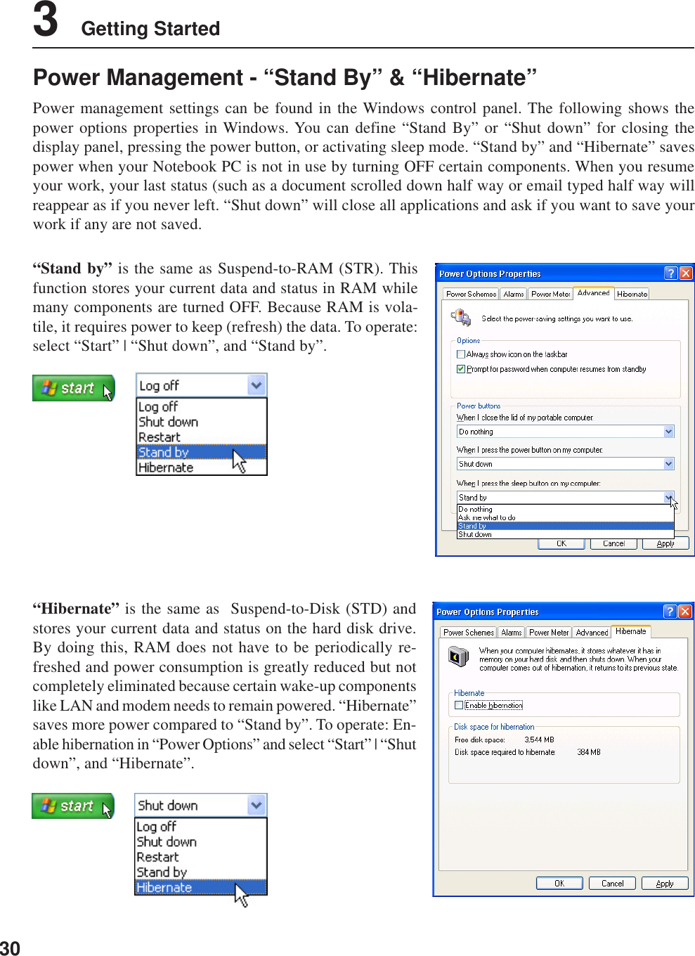
![55Using the Notebook PC 4Power Management ModesThe Notebook PC has a number of automatic or adjustable power saving features that you can use tomaximize battery life and lower Total Cost of Ownership (TCO). You can control some of these fea-tures through the Power menu in the BIOS Setup. ACPI power management settings are made throughthe operating system. The power management features are designed to save as much electricity aspossible by putting components into a low power consumption mode as often as possible but also allowfull operation on demand. These low power modes are referred to as “Stand by” (or Suspend-to-RAM)and “Hibernation” mode or Suspend-to-Disk (STD). The Standby mode is a simple function providedby the operating system. When the Notebook PC is in either one of the power saving modes, the statuswill be shown by the following: “Stand by”: Power LED Blinks and “Hibernation”: Power LED OFF.Full Power Mode & Maximum PerformanceThe Notebook PC operates in Full Power mode when the power management function is disabled byconfiguring Windows power management and SpeedStep. When the Notebook PC is operating in FullPower Mode, the Power LED remains ON. If you are conscious of both system performance and powerconsumption, select “Maximum Performance” instead of disabling all power management features.ACPIAdvanced Configuration and Power Management (ACPI) was developed by Intel, Microsoft, and Toshibaespecially for Windows and later to control power management and Plug and Play features. ACPI is thenew standard in power management for Notebook PCs.NOTE: APM was used in older operating systems like Windows NT4 and Windows 98.Because newer operating systems like Windows XP, Windows 2000, and Windows MEutilize ACPI, APM is no longer fully supported on this Notebook PC.Suspend ModeIn “Stand by” (STR) and “Hibernation” (STD), the CPU clock is stopped and most of the Notebook PCdevices are put in their lowest active state. The suspend mode is the lowest power state of the NotebookPC. The Notebook PC enters suspend mode when the system remains idle for a specified amount of timeor manually using the [Fn][F1] keys. The Power LED blinks when the Notebook PC is in STR mode. InSTD mode, the Notebook PC will appear to be powered OFF. Recover from STR by pressing anykeyboard button (except Fn). Recover from STD by using the power switch (just like poweringON the Notebook PC).](https://usermanual.wiki/ASUSTeK-Computer/B2200BG/User-Guide-440585-Page-57.png)
![564 Using the Notebook PCThermal Power ControlThere are three power control methods for controlling the Notebook PC’s thermal state. These powercontrol cannot be configured by the user and should be known in case the Notebook PC should enterthese states. The following temperatures represent the chassis temperature (not CPU).• The fan turns ON for active cooling when the temperature reaches the safe upper limit.• The CPU decreases speed for passive cooling when the temperature exceeds the safe upper limit.• The system shut down for critical cooling when temperature exceeds the maximum safe upper limit.Power SavingsIn addition to reducing the CPU clock, this mode puts devices including the LCD backlight in theirlower active state. The Notebook PC enters “Stand by” mode (low priority) when the system remainsidle for a specified amount of time. The timeout can be set through Windows power management(higher priority). To resume system operation, press any key.Power State SummarySTATE ENTRY EVENT EXIT EVENT“Stand by” • “Stand by” through Windows Start button, • Any device• Timer as set though “Power Management” • Battery low in Windows Control Panel (higher priority)STR (“Stand by”) • Hotkey [Fn][F1] • Signal from modem port(Suspend-to-RAM) -- • Power button • Any keySTD (“Hibernate”) • Hotkey [Fn][F1] • Power button(Suspend-to-Disk) -- • Battery Extremely LowSoft OFF • Power button (can be defined as STR or STD) • Power button• “Shut down” through Windows Start button](https://usermanual.wiki/ASUSTeK-Computer/B2200BG/User-Guide-440585-Page-58.png)