ASUSTeK Computer B2915ABG Laptop with WLAN User Manual 01 30 Z61A M3N p65
ASUSTeK Computer Inc Laptop with WLAN 01 30 Z61A M3N p65
UserManual.wiki
>
ASUSTeK Computer
>
B2915ABG User Manual
Users Manual
Navigation menu
Upload a User Manual
Namespaces
Wiki Guide
HTML
PDF
Info
Views
User Manual
Discussion / Help
Navigation


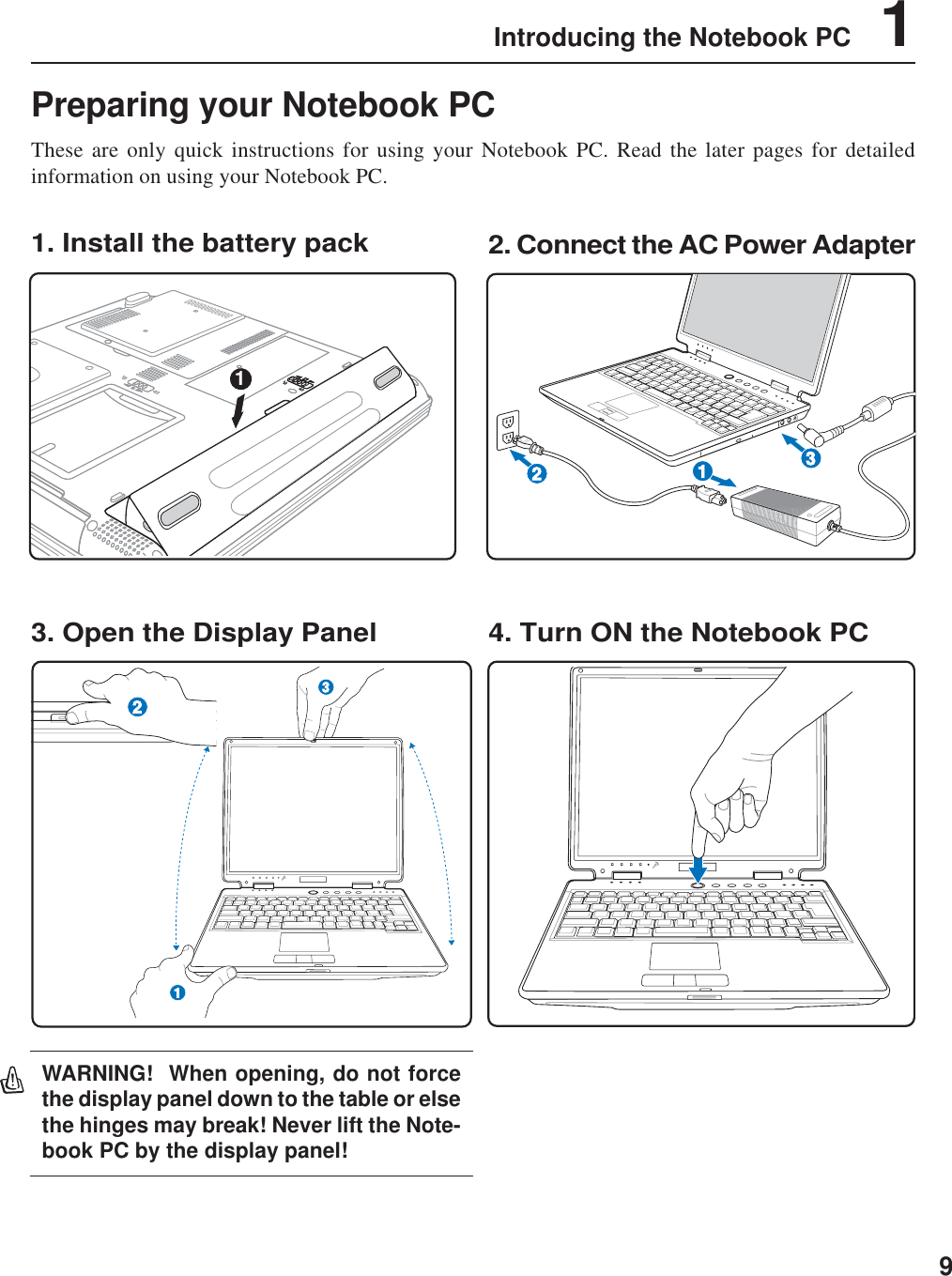
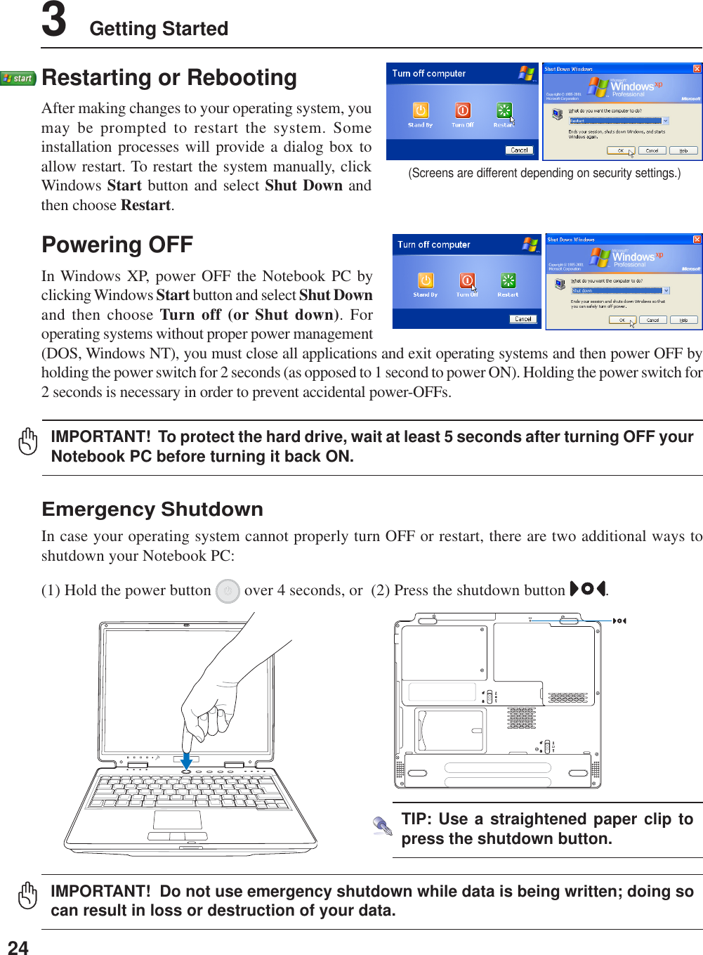
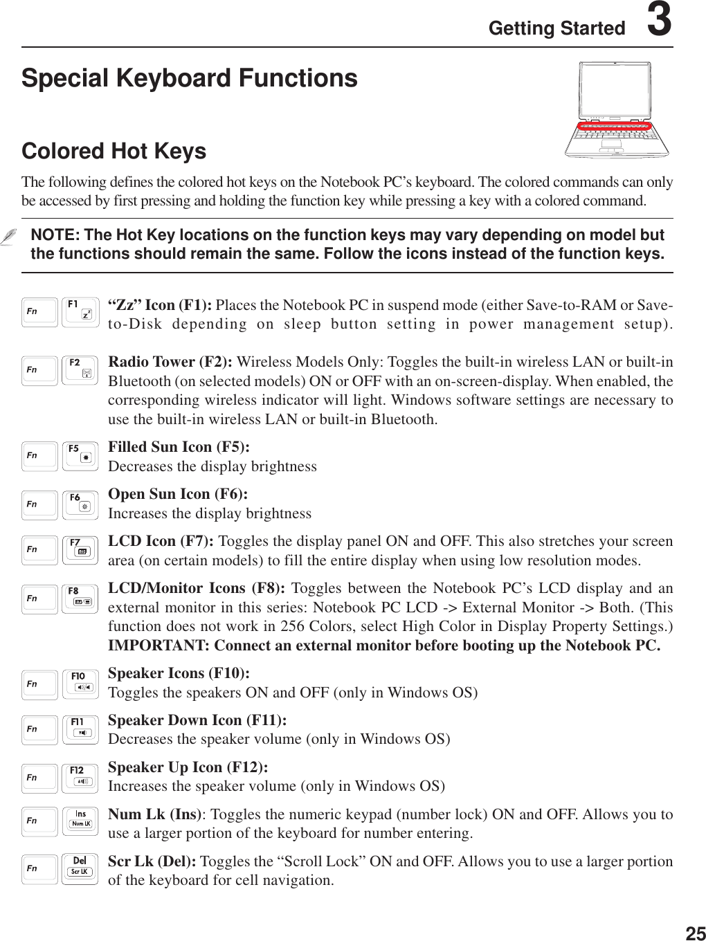
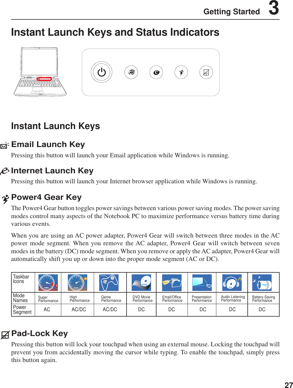
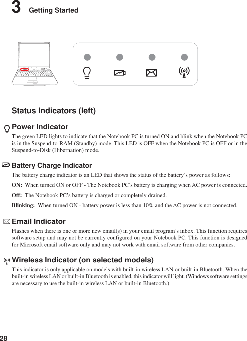
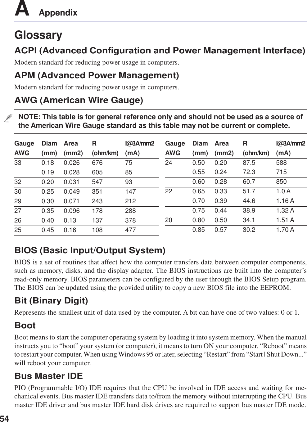
![61 Introducing the Notebook PCAbout This User’s ManualYou are reading the Notebook PC User’s Manual. This User’s Manual provides information on thevarious components in the Notebook PC and how to use them. The following are major sections of thisUser’s Manuals:1. Introducing the Notebook PCIntroduces you to the Notebook PC and this User’s Manual.2. Knowing the PartsGives you information on the Notebook PC’s components.3. Getting StartedGives you information on getting started with the Notebook PC.4. Using the Notebook PCGives you information on using the Notebook PC’s components.5. AppendixIntroduces you to optional accessories and gives additional information.Notes For This ManualA few notes and warnings in bold are used throughout this guide that you should be aware of in order tocomplete certain tasks safely and completely. These notes have different degrees of importance asdescribed below:NOTE: Tips and information for spe-cial situations.TIP: Tips and useful information forcompleting tasks.Text enclosed in < > or [ ] represents a key on the keyboard; do not actually type the< > or [ ] and the enclosed letters.< >[ ]WARNING! Important information thatmust be followed for safe operation.IMPORTANT! Vital information thatmust be followed to prevent damageto data, components, or persons.User’s Manual](https://usermanual.wiki/ASUSTeK-Computer/B2915ABG/User-Guide-559031-Page-6.png)


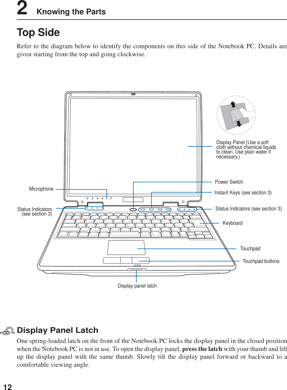
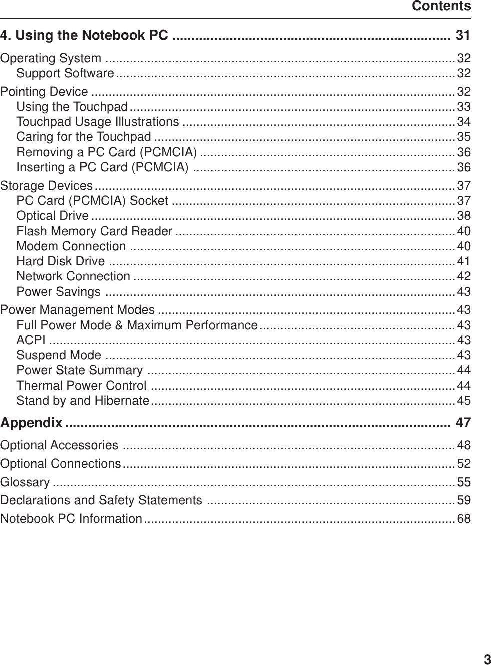
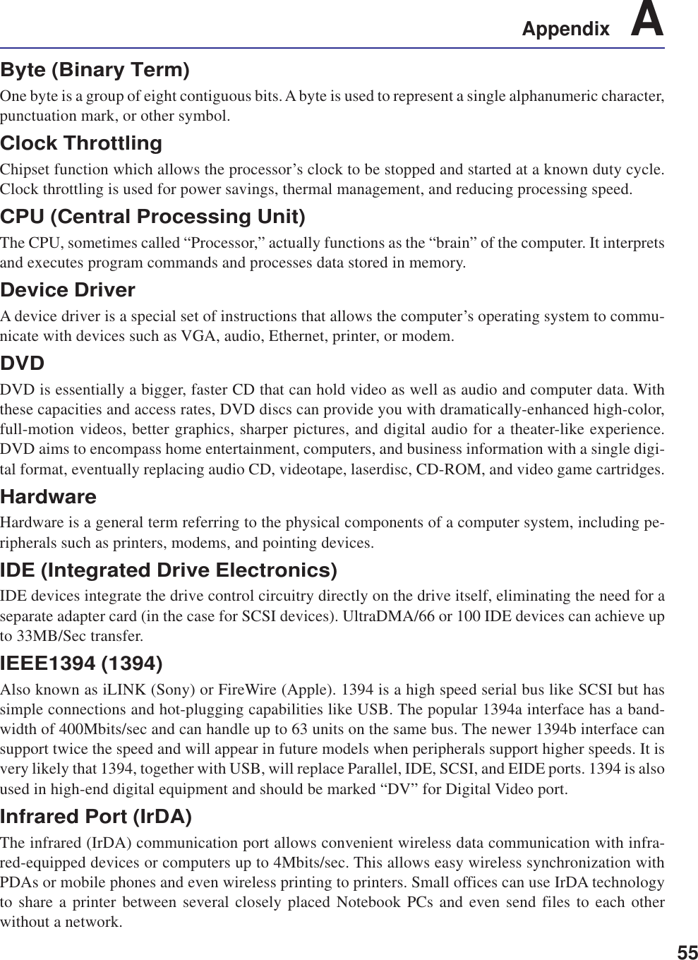
![223 Getting StartedThe Power-On Self Test (POST)When you turn ON the Notebook PC, it will first run through a series of software-controlled diagnostictests called the Power-On Self Test (POST). The software that controls the POST is installed as apermanent part of the Notebook PC’s architecture. The POST includes a record of the Notebook PC’shardware configuration, which is used to make a diagnostic check of the system. This record is createdby using the BIOS Setup program. If the POST discovers a difference between the record and theexisting hardware, it will display a message on the screen prompting you to correct the conflict byrunning BIOS Setup. In most cases the record should be correct when you receive the Notebook PC.When the test is finished, you may get a message reporting “No operating system found” if the harddisk was not preloaded with an operating system. This indicates that the hard disk is correctly detectedand ready for the installation of a new operating system.The S.M.A.R.T. (Self Monitoring and Reporting Technology) checks the hard disk drive during POSTand gives a warning message if the hard disk drive requires servicing. If any critical hard disk drivewarning is given during bootup, backup your data immediately and run Windows disk checking program.To run Window’s disk checking program: (1) right-click any hard disk drive icon in “My Computer”, (2)choose Properties, (3) click the Tools tab, (4) click Check Now, (5) select a hard disk drive, (6) selectThorough to also check for physical damages, and (7) click Start. Third party disk utilities such as Symantec’sNorton Disk Doctor can also perform the same functions but with greater ease and more features.Powering ON the Notebook PCThe Notebook PC’s power-ON message appears on the screen when you turn it ON. If necessary, you mayadjust the brightness by using the hot keys. If you need to run the BIOS Setup to set or modify the systemconfiguration, press [F2] upon bootup to enter the BIOS Setup. If you press [Tab] during the splashscreen, standard boot information such as the BIOS version can be seen. Press [ESC] and you will bepresented with a boot menu with selections to boot from your available drives.NOTE: Before bootup, the display panel flashes when the power is turned ON. This ispart of the Notebook PC’s test routine and is not a problem with the display.IMPORTANT! If warnings are still given during bootup after running a software diskchecking utility, you should take your Notebook PC in for servicing. Continued usemay result in data loss.IMPORTANT! To protect the hard disk drive, always wait at least 5 seconds afterturning OFF your Notebook PC before turning it back ON.](https://usermanual.wiki/ASUSTeK-Computer/B2915ABG/User-Guide-559031-Page-22.png)
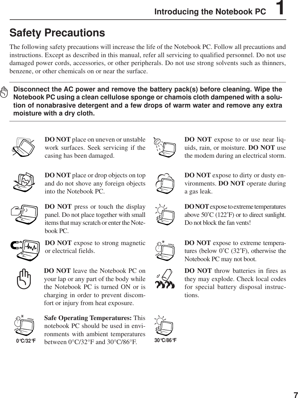
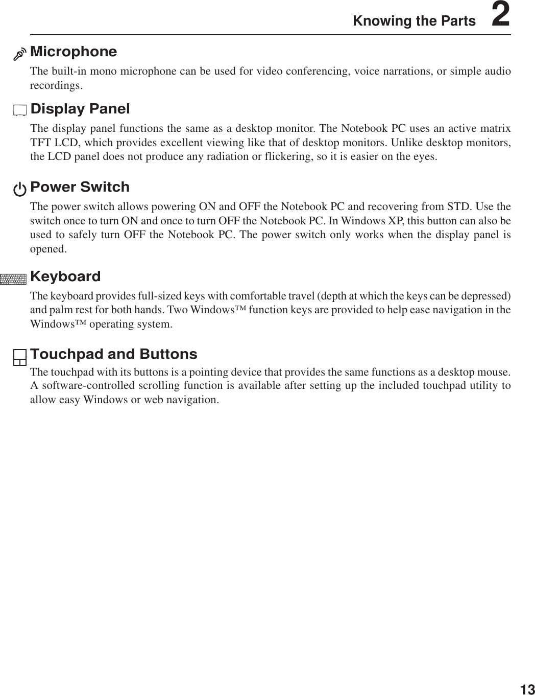
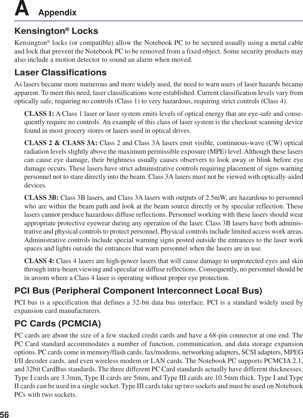
![263 Getting StartedKeyboard as a Numeric KeypadThe numeric keypad is embedded in the keyboard andconsists of 15 keys that make number intensive input moreconvenient. These dual-purpose keys are labeled in orangeon the key caps. Numeric assignments are located at theupper right hand corner of each key as shown in the figure.When the numeric keypad is engaged by pressing ,the number lock LED lights up. If an external keyboard isconnected, pressing the on the external keyboardenables/disables the NumLock on both keyboardssimultaneously. To disable the numeric keypad while keeping the keypad on an external keyboardactivated, press the keys on the Notebook PC.Microsoft Windows™ KeysThere are two special Windows™ keys on the keyboard as described below.The key with the Windows™ Logo activates the Start menu located at the bottom left of theWindows™ desktop.The other key, that looks like a Windows™ menu with a small cursor, activates the propertiesmenu and is equivalent to pressing the right mouse button on a Windows™ object.Keyboard as CursorsThe keyboard can be used as cursors while Number Lock isON or OFF in order to increase navigation ease whileentering numeric data in spreadsheets or similar applications.With Number Lock OFF, press and one of the cursorkeys shown below. For example [Fn][8] for up, [Fn][K] fordown, [Fn][U] for left, and [Fn][O] for right.With Number Lock ON, use [Shift] and one of the cursorkeys shown below. For example [Shift][8] for up, [Shift][K]for down, [Shift][U] for left, and [Shift][O] for right.NOTE: The arrow symbols are illustrated here for your reference. They are not labeledon the keyboard as shown here.](https://usermanual.wiki/ASUSTeK-Computer/B2915ABG/User-Guide-559031-Page-26.png)
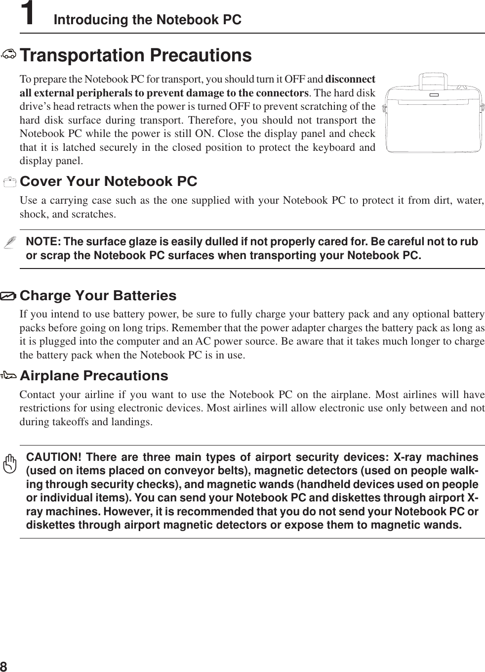
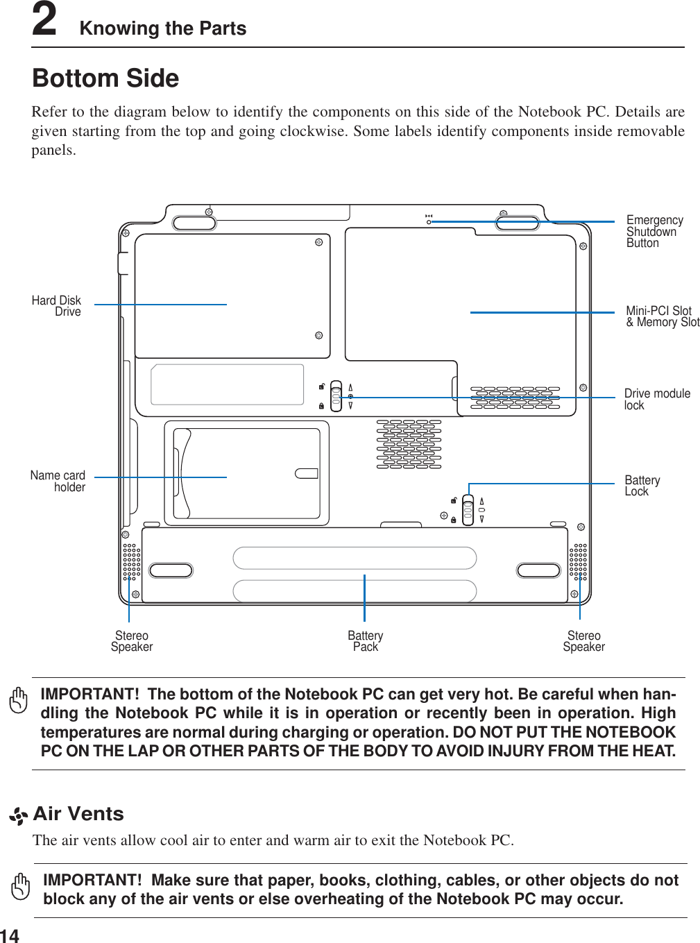
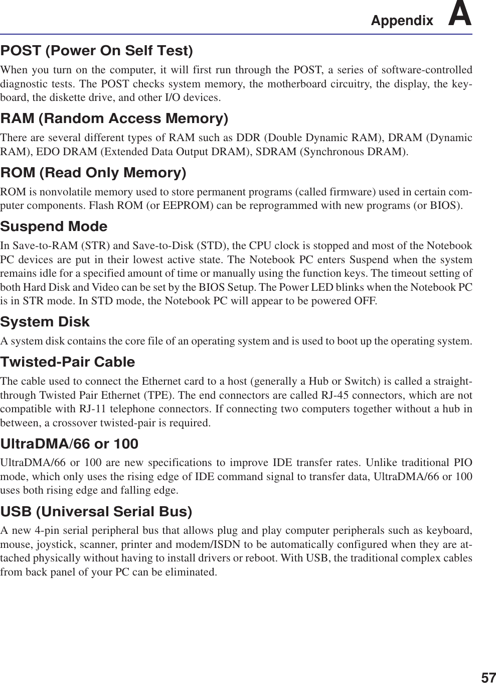
![29Getting Started 3Status Indicators (right)Drive Activity IndicatorIndicates that the Notebook PC is accessing one or more storage device(s) such as the hard disk. Thelight flashes proportional to the access time.Number LockIndicates that number lock [Num Lk] is activated when lighted. Number lock allows some of the keyboardletters to act as numbers for easier numeric data input.Capital LockIndicates that capital lock [Caps Lock] is activated when lighted. Capital lock allows some of thekeyboard letters to type using capitalized letters (e.g. A, B, C). When the capital lock light is OFF, thetyped letters will be in the lower case form (e.g. a,b,c).Scroll LockIndicates that scroll lock [Scr Lk] is activated when lit. Scroll lock allows some ofthe keyboard letters to act as direction keys in order to allow easier navigationwhen only a part of the keyboard is required, such as for playing games.](https://usermanual.wiki/ASUSTeK-Computer/B2915ABG/User-Guide-559031-Page-29.png)

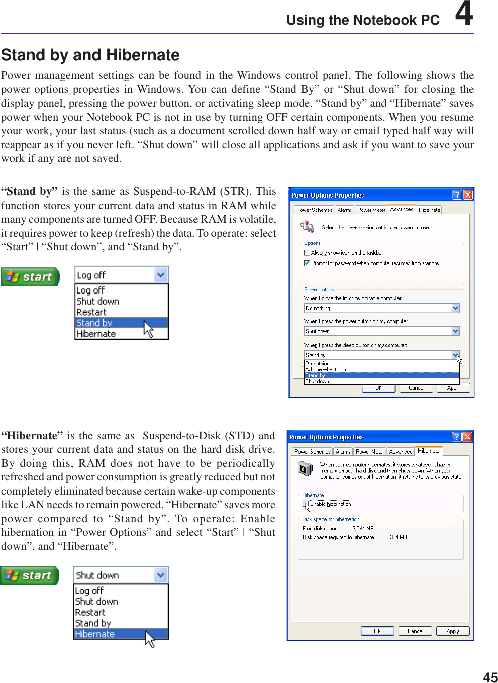
![43Using the Notebook PC 4Power Management ModesThe Notebook PC has a number of automatic or adjustable power saving features that you can use tomaximize battery life and lower Total Cost of Ownership (TCO). You can control some of these featuresthrough the Power menu in the BIOS Setup. ACPI power management settings are made through theoperating system. The power management features are designed to save as much electricity as possibleby putting components into a low power consumption mode as often as possible but also allow fulloperation on demand. These low power modes are referred to as “Stand by” (or Suspend-to-RAM) and“Hibernation” mode or Suspend-to-Disk (STD). The Standby mode is a simple function provided bythe operating system. When the Notebook PC is in either one of the power saving modes, the status willbe shown by the following: “Stand by”: Power LED Blinks and “Hibernation”: Power LED OFF.Full Power Mode & Maximum PerformanceThe Notebook PC operates in Full Power mode when the power management function is disabled byconfiguring Windows power management and SpeedStep. When the Notebook PC is operating in FullPower Mode, the Power LED remains ON. If you are conscious of both system performance and powerconsumption, select “Maximum Performance” instead of disabling all power management features.ACPIAdvanced Configuration and Power Management (ACPI) was developed by Intel, Microsoft, and Toshibaespecially for Windows and later to control power management and Plug and Play features. ACPI is thenew standard in power management for Notebook PCs.NOTE: APM was used in older operating systems like Windows NT4 and Windows 98.Because newer operating systems like Windows XP, Windows 2000, and Windows MEutilize ACPI, APM is no longer fully supported on this Notebook PC.Suspend ModeIn “Stand by” (STR) and “Hibernation” (STD), the CPU clock is stopped and most of the Notebook PCdevices are put in their lowest active state. The suspend mode is the lowest power state of the NotebookPC. The Notebook PC enters suspend mode when the system remains idle for a specified amount of timeor manually using the [Fn][F1] keys. The Power LED blinks when the Notebook PC is in STR mode. InSTD mode, the Notebook PC will appear to be powered OFF. Recover from STR by pressing anykeyboard button (except Fn). Recover from STD by using the power switch (just like poweringON the Notebook PC).Power SavingsIn addition to reducing the CPU clock, this mode puts devices including the LCD backlight in theirlower active state. The Notebook PC enters “Stand by” mode (low priority) when the system remainsidle for a specified amount of time. The timeout can be set through Windows power management (higherpriority). To resume system operation, press any key.](https://usermanual.wiki/ASUSTeK-Computer/B2915ABG/User-Guide-559031-Page-43.png)
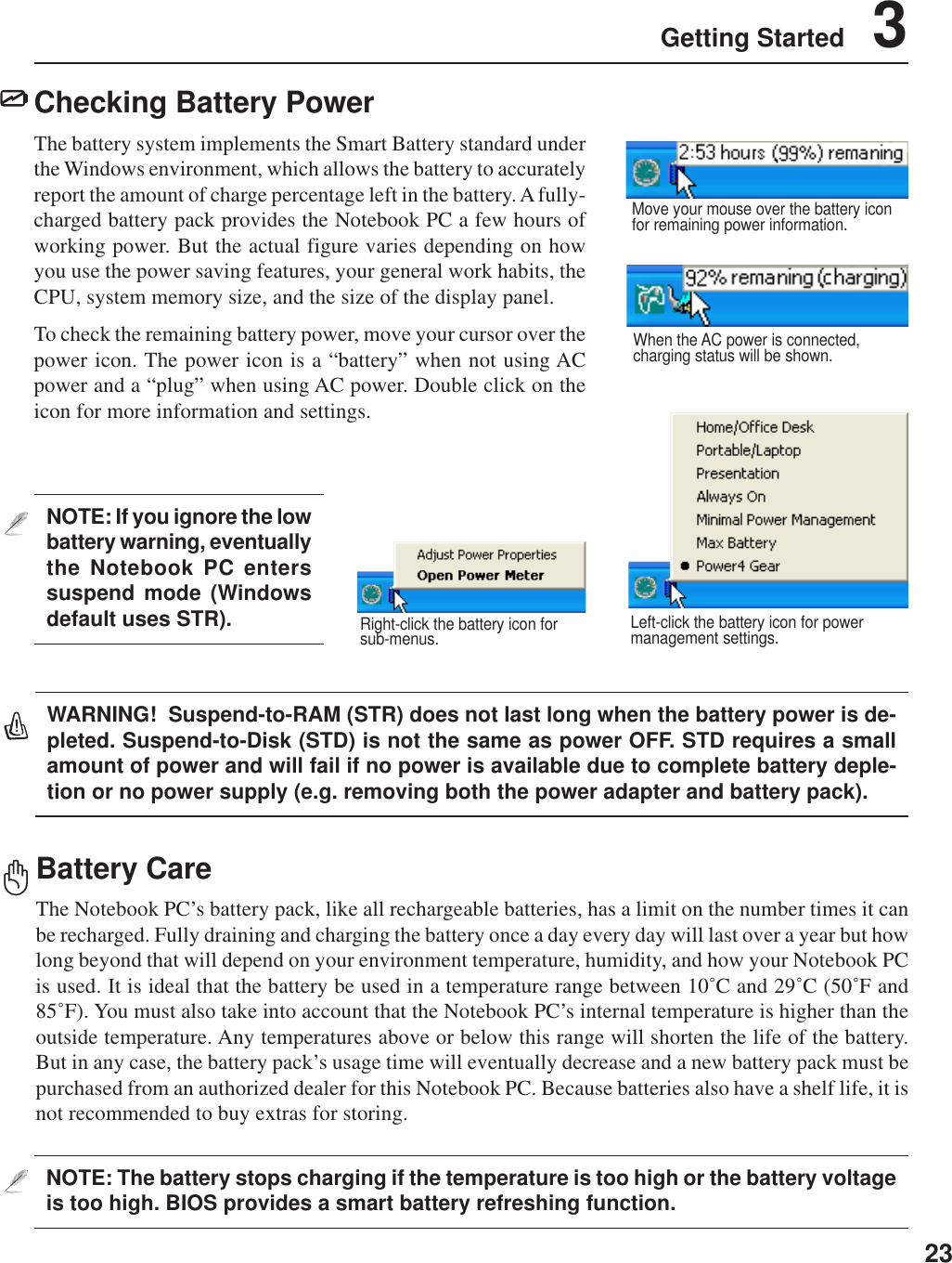
![444 Using the Notebook PCPower State SummarySTATE ENTRY EVENT EXIT EVENT“Stand by” • “Stand by” through Windows Start button, • Any device• Timer as set though “Power Management” • Battery low in Windows Control Panel (higher priority)STR (“Stand by”) • Hotkey [Fn][F1] • Signal from modem port(Suspend-to-RAM) -- • Power button • Any keySTD (“Hibernate”) • Hotkey [Fn][F1] • Power button(Suspend-to-Disk) -- • Battery Extremely LowSoft OFF • Power button (can be defined as STR or STD) • Power button• “Shut down” through Windows Start buttonThermal Power ControlThere are three power control methods for controlling the Notebook PC’s thermal state. These powercontrol cannot be configured by the user and should be known in case the Notebook PC should enterthese states. The following temperatures represent the chassis temperature (not CPU).• The fan turns ON for active cooling when the temperature reaches the safe upper limit.• The CPU decreases speed for passive cooling when the temperature exceeds the safe upper limit.• The system shut down for critical cooling when temperature exceeds the maximum safe upper limit.](https://usermanual.wiki/ASUSTeK-Computer/B2915ABG/User-Guide-559031-Page-44.png)


![62A AppendixFCC Radio Frequency Interference RequirementsMPE Statement: Your device contains a low power transmitter. When device is transmitted it sends outRadio Frequency (RF) signal.This device is restricted to INDOOR USE due to its operation in the 5.15 to 5.25GHz frequency range. FCCrequires this product to be used indoors for the frequency range 5.15 to 5.25GHz to reduce the potential forharmful interference to co-channel of the Mobile Satellite Systems.High power radars are allocated as primary user of the 5.25 to 5.35GHz and 5.65 to 5.85GHz bands. Theseradar stations can cause interference with and / or damage this device.This device and its antenna(s) must not be co-located or operating in conjunction with any other antenna ortransmitter.FCC RF Exposure Guidelines (Wireless Clients)This device has been tested for compliance with FCC RF Exposure (SAR) limits in typical portableconfigurations. In order to comply with SAR limits established in the ANSI C95.1 standards, it is recommendedwhen using a wireless LAN adapter that the integrated antenna is positioned more than [2.5cm] from yourbody or nearby persons during extended periods of operation. If the antenna is positioned less than [2.5cm]from the user, it is recommended that the user limit the exposure time.FCC Radio Frequency Exposure Caution StatementUse only with supplied antenna. Unauthorized antenna, modification, or attachments could damage thetransmitter and may violate FCC regulations. Any changes of modifications not expressly approved by thegrantee of this device could void the users authority to operate the equipment.Installation and use of this wireless LAN device must be in strict accordance with the instructions includedin the user documentation provided with the product. Any changes or modifications (including the antennas)made to this device that are not expressly approved by the manufacturer may void the user’s authority tooperate the equipment. The manufacturer is not responsible for any radio or television interference causedby unauthorized modification of this device, or the substitution or attachment of connecting cables andequipment other than manufacturer specified. It is the responsibility of the user to correct any interferencecaused by such unauthorized modification, substitution or attachment. Manufacturer and its authorized resellersor distributors will assume no liability for any damage or violation of government regulations arising fromfailing to comply with these guidelines.Declaration of Conformity (R&TTE directive 1999/5/EC)The following items were completed and are considered relevant and sufficient:• Essential requirements as in [Article 3]• Protection requirements for health and safety as in [Article 3.1a]• Testing for electric safety according to [EN 60950]• Protection requirements for electromagnetic compatibility in [Article 3.1b]• Testing for electromagnetic compatibility in [EN 301 489-1] & [EN 301]• Testing according to [489-17]• Effective use of the radio spectrum as in [Article 3.2]• Testing for radio test suites according to [EN 300 328-2]](https://usermanual.wiki/ASUSTeK-Computer/B2915ABG/User-Guide-559031-Page-62.png)