ASUSTeK Computer J3NWM3B2200 Notebook PC User Manual XP731GB Cover p65
ASUSTeK Computer Inc Notebook PC XP731GB Cover p65
UserManual.wiki
>
ASUSTeK Computer
>
J3NWM3B2200 User Manual
User Manual
Navigation menu
Upload a User Manual
Namespaces
Wiki Guide
HTML
PDF
Info
Views
User Manual
Discussion / Help
Navigation


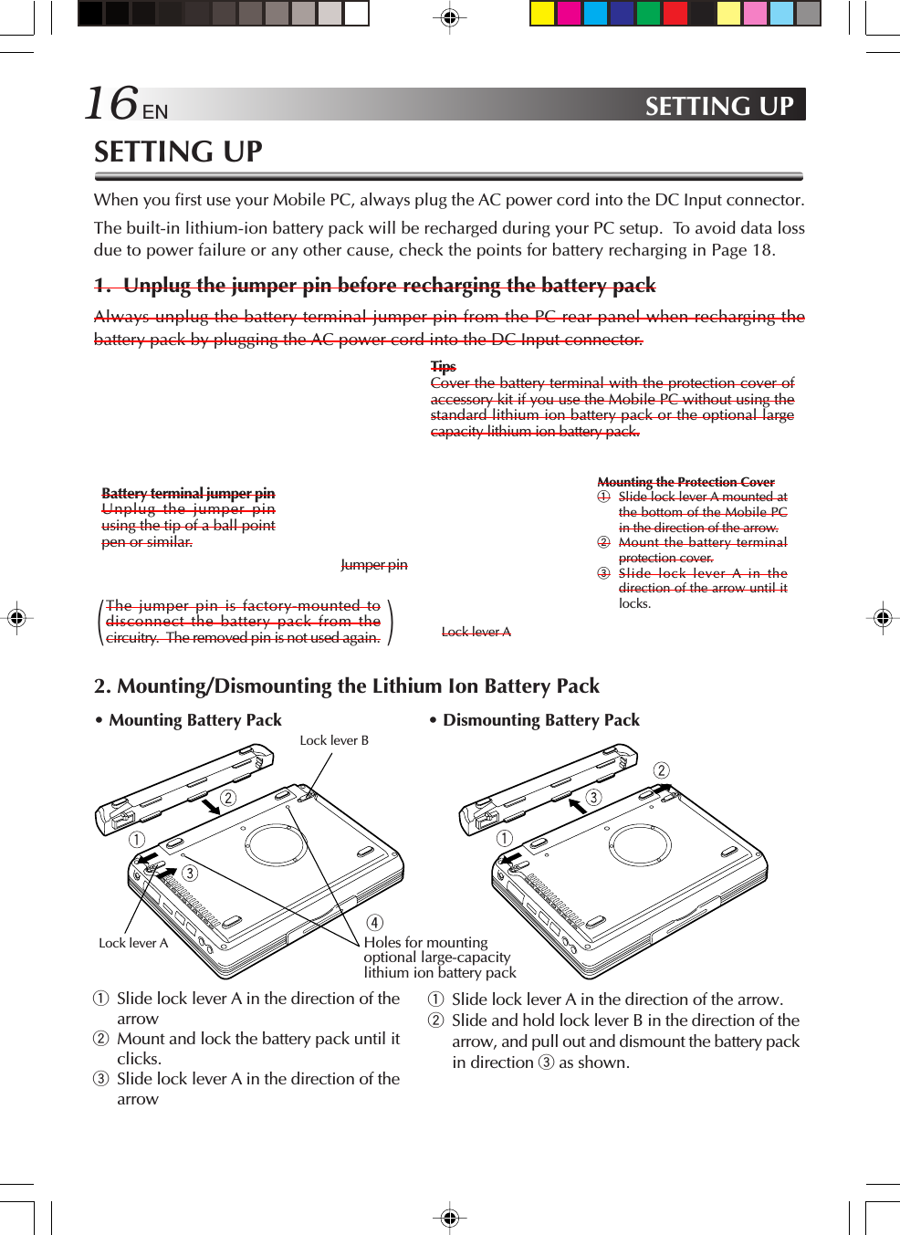
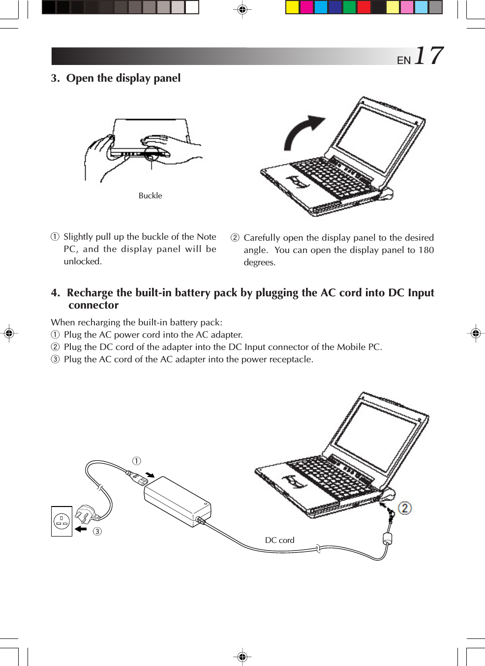
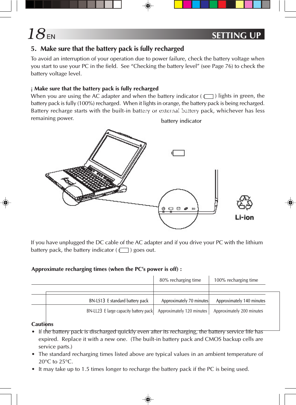
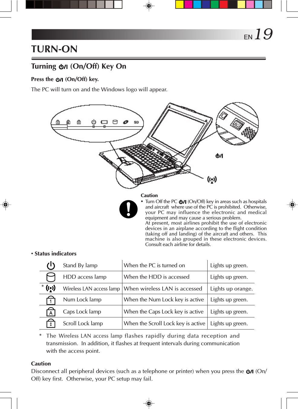
![20 ENInitial Setup of Microsoft WindowsWhen using your PC for first time, you must prepare to use Microsoft Windows.Once you have finished the initial Windows setup, you can use the software and various PCfunctions. Use the following procedure to initially set up Microsoft Windows.For pointing device and keyboard operations, see Pages 54 to 56.1. When the “Welcome to Microsoft Windows” screen appears, click [Next] at theright lower corner of the screen.The “The End User License Agreement” screen will appear.2. Read the “The End User License Agreement” information and click “Yes, I accept”option if you accept the agreement. Then, click [Next].The “What’s your computer’s name?” screen will appear.NoteIf you select the “No, I don’t accept” option, the initial Windows setup is cancelled. Youcannot use the Microsoft Windows and the PC software.3. Rename your computer and click [Next].The “An Internet connection could not be chosen” or “How will this computer connect tothe Internet?” screen appears.TipsA unique computer name is required so that your PC is distinguished from other computersif you connect your PC to the network. Although the PC is named automatically and shownin the “Computer name” column, you can change it to a name which is easy to remember.4. Click [Next].The “Ready to register with Microsoft?” screen appears.5. Click “No, not at this time” option, and click [Next].The “Who will use this computer?” screen may appear.TipsIf you select “Yes, I’d like to register with Microsoft now” option, you can start online userregistration. For Internet connection setup, see Page 36 “To Connect to the Internet” section.TURN-ON](https://usermanual.wiki/ASUSTeK-Computer/J3NWM3B2200/User-Guide-404501-Page-20.png)
![EN216. Enter the user name and click [Next].The “Thank you!” screen will appear.TipsThe name you have entered is shown on the “welcome” screen that appears when you turnthe PC power switch on after initial Windows setup. To start up Microsoft Windows, clickthe user name shown on the screen.7. Click [Finish].The initial Windows setup has completed.Cautions• No guarantees are made for operation if an operating system other than the one alreadyinstalled in your PC is installed.•When a week has passed after initial startup of the Microsoft Windows, a confirmationscreen asking for the deletion of desktop icons appears.This is the Desktop Cleanup program that can delete icons that you have not used for acertain period from the desktop screen. The software is not deleted even if you havecleared its icon from the desktop screen.•Use the following procedure to change the Windows date and time.1. Double-click the time display in the task tray at the lower right of the desktop. The“Date and Time Properties” dialog box appears.2. Click the “Time Zone” tab and select your time zone from the list box.3. Click the “Date & Time” tab and enter the correct date and time.4. Click “OK” to save your change.](https://usermanual.wiki/ASUSTeK-Computer/J3NWM3B2200/User-Guide-404501-Page-21.png)
![22 ENTurn-OffCaution• Always use this procedure to turn off the PC. Otherwise, your PC may fail.1. Click [start].The “start” menu will appear.2. Click [Turn Off computer].The “Turn off computer” screen will appear.3. Click [Turn Off].The PC will be turned off automatically, and (Stand By) lamp will go out.Before closing the LCD panel, make sure that (Stand By) lamp has turned off.TipsTo restart Windows without turning off the power, click [Restart] on the “Turn off computer”screen. Alternatively, press the [Shift] button on the keyboard while “Turn off computer”screen is displayed. The screen below will appear and the PC can be put into [Hibernate].For details on the [Stand By] and [Hibernate] modes, refer to pages 77 and 78.TURN-ON](https://usermanual.wiki/ASUSTeK-Computer/J3NWM3B2200/User-Guide-404501-Page-22.png)
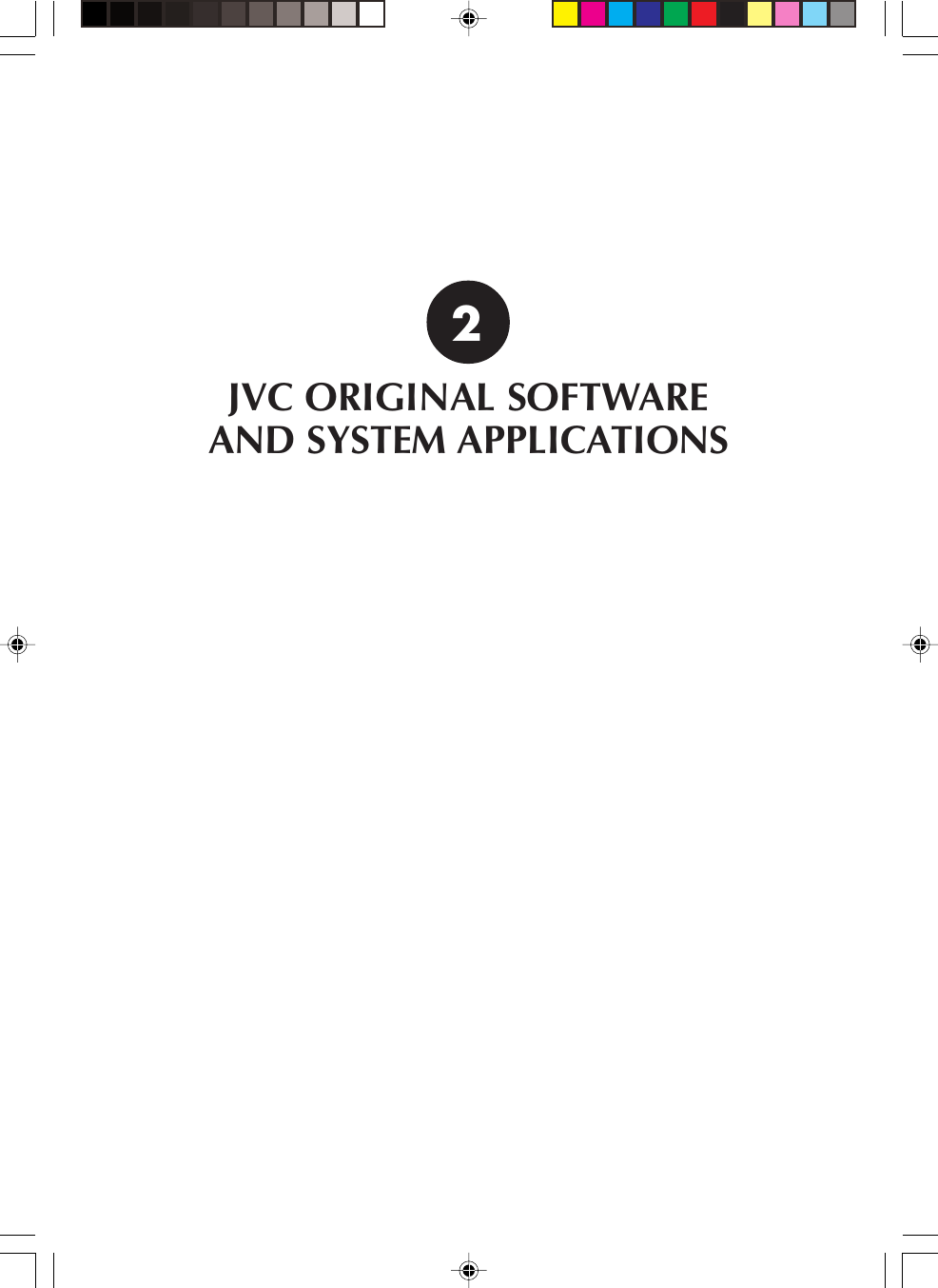
![24 ENJVC ORIGINAL SOFTWARE AND SYSTEM APPLICATIONSJVC ORIGINAL SOFTWARETo use the JVC original software, you must set it up in the “Setup of JVC Original Software” givenbelow. You can setup the following software programs.Setup software• CC converter (See Page 27.)• JVC’s DVC (Digital Video Camera) utilitiesTips•The JVC’s DVC utilities are USB drivers dedicated to GR-DV4000EK, DV3500EK, DV3000EK,DV2000EK, DV700EK, DV600EK, DV500EK, DV400EK, DX300EK, DX100EK, DX95EK,DX75EK, DX70EK, DX60EK, DX55EK, DX45EK, DX35EK, DX25EK, DV70EK, DV60EK,D50EK, D40EK, DVP9EK, DVP8EK, DVP7EK and DVP3EK systems. If you are using any ofthese DVC’s, you can use it without uploading the USB driver from the DVC’s CD-ROMdisk.•For DVC connection and operations, see its instruction manual.Setup of JVC Original SoftwareBefore starting the software setup, quit and save the currently active application if any. Otherwise,your working data will be lost.1. Click [start] and click [Run first] at the right lower end of the Menu.The “Preparing to Install... ” screen will appear, and the software setup will start up.2. Read the License Agreement when displayed.If you accept the Agreement, click [Yes]3. During setup, the “Sound, video and game controllers has not passed WindowsLogo testing to verify its compatibility with Windows XP.” message may bedisplayed. Ignore it as it does not affect the system operation. Click [ContinueAnyway] to continue software setup.](https://usermanual.wiki/ASUSTeK-Computer/J3NWM3B2200/User-Guide-404501-Page-24.png)
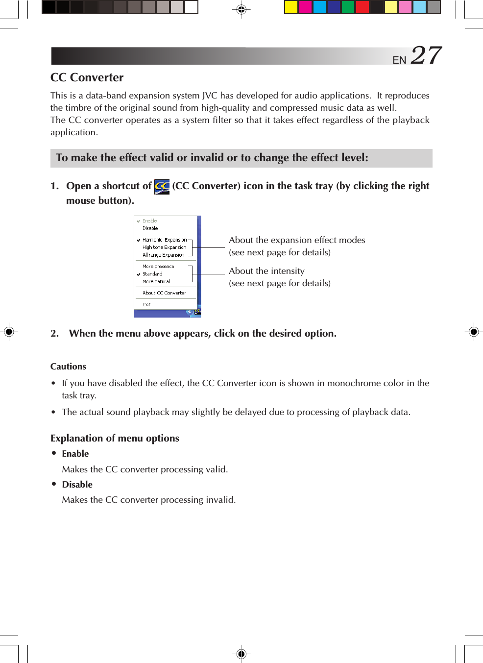
![EN 254. When the software has been set up, a prompt for PC restarting appears. Click[Finish] to restart the PC.CautionThis setup cannot install all DVC utilities.After you have set up the original software, plug the DVC cable into the USB socket of yourPC. The device type will be recognized automatically and setup of its USB driver will startup.DVC’s USB DriversThe DVC connection and the USB driver to be set up vary depending on the DVC model you use.For details, see the DVC instruction manual.1. Connect the DVC to the USB connector of your PC.2. The hardware installation screen will appear.3. Select the “Install the software automatically” option and click [Next].Cautions•The driver to be set up depends on the DVC operation mode.•There is no operation problem although the “has not passed Windows Logo testing…”message appears.Continue to next page](https://usermanual.wiki/ASUSTeK-Computer/J3NWM3B2200/User-Guide-404501-Page-25.png)
![26 EN4. Click [Continue Anyway].The driver will be installed automatically.5. When “Completing the Found New Hardware Wizard” message appears, click[Finish].CautionAs your PC has two USB ports, you need to set up both of them if you use them. If you areprompted to set up the USB port when you attach a device to it, repeat the above procedureagain.JVC ORIGINAL SOFTWARE AND SYSTEM APPLICATIONS](https://usermanual.wiki/ASUSTeK-Computer/J3NWM3B2200/User-Guide-404501-Page-26.png)
![EN 29•About CC converterShows the CC converter version and other information.Click [OK] to close the displayed subwindow.•ExitQuits the CC converter. The CC converter status you have set at this point is held. If you wishto restart the CC converter, you can start up the program from the Start menu.Cautions•Do not change the sound playback device when you are playing back the sound data (suchas an audio file).•If you have changed the sound playback device, wait five (5) or more seconds before playingback the data.•The CC converter can process two-channel PCM data only. A sound device may transfermulti-channel data or non-PCM data, but the CC converter cannot process such data.•If you play back data having a high noise level, the noise may be emphasized.•Users other than the computer administrator (even if they have the Administrator’s authority)may not change the CC converter setup.PD-TS decorderThis decoder is designed to capture, using a separate personal computer (Pentium 4, 2 GHz orfaster recommended), the data which has been shot in the GR-PD1 HI-RES. mode or PS50 modeand play the data using the Windows Media(TM) Player 9 of this unit (MP-XP731GB) in a simplifiedformat (at a speed of about 3 frames per second), and it is pre-installed.•To uninstall the decoder, select [Add/Remove Programs] and delete it.•The installer is included on the application CD-ROM so use the CD-ROM provided if youneed to re-install the decoder.](https://usermanual.wiki/ASUSTeK-Computer/J3NWM3B2200/User-Guide-404501-Page-29.png)
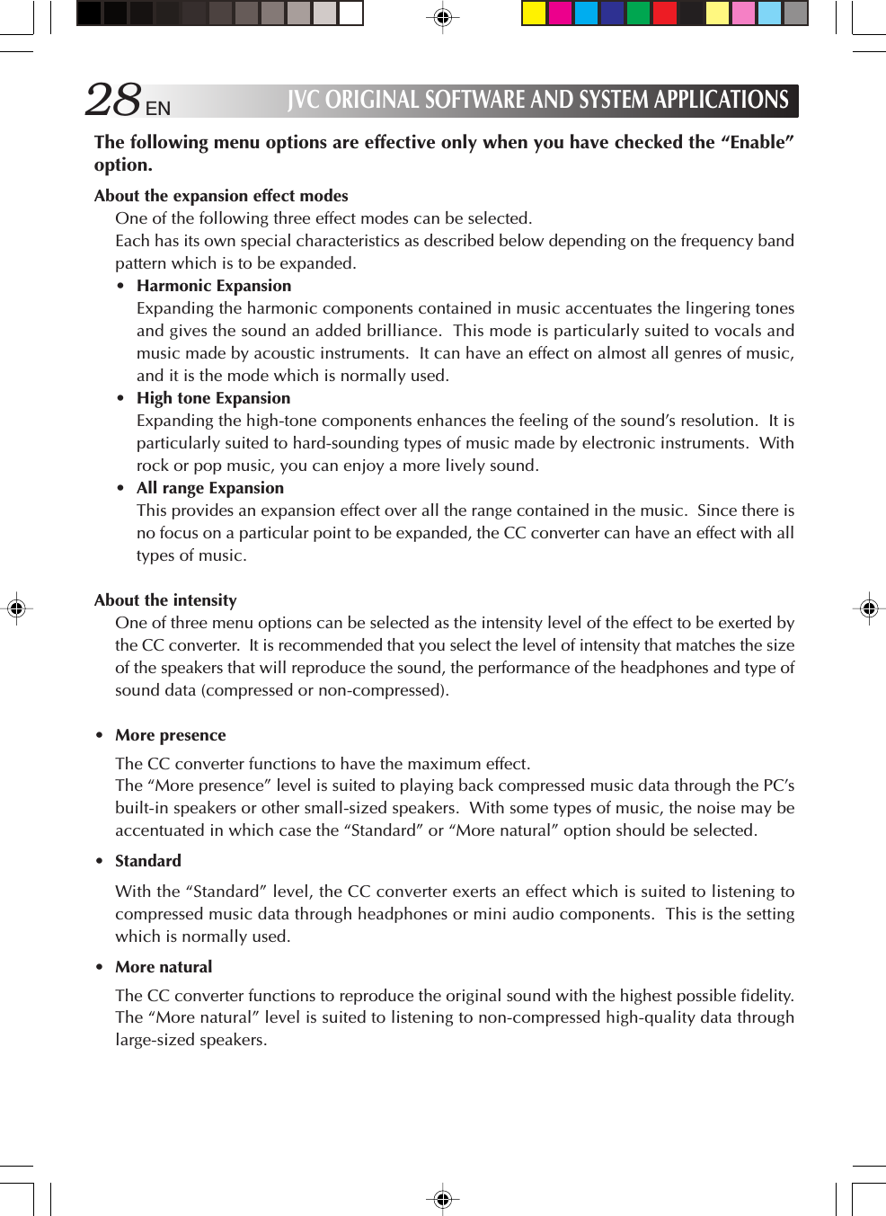
![30 ENJVC ORIGINAL SOFTWARE AND SYSTEM APPLICATIONSEasy Network ChangerThe Easy Network Changer is a network setting utility which enables network settings to bechanged easily.This utility makes it possible to register a multiple number of profiles that define the networksettings for use at home, in the office or other connection locations. When InterLink has beenmoved to a different network environment, it allows easy connection to a network by selectingthe corresponding profile.To start the utilityDouble-click the Easy Network Changer icon on the desktop.The profile management screen now appears. To register a profile, click [New] and follow theinstructions given by the Wizard. Once a profile has been registered, it can be selected from theprofile management screen and the network settings can be changed. An easy way to change thenetwork is to click the icon on the task tray and select the profile from the menu which isthen displayed.The registered profiles are displayed, and thenetwork is connected by selecting one ofthese profiles. (The check mark indicatesthe profile which is being used.)This is used to disconnect the network.This is used to display the help information.This is used to display the versioninformation.This is used to exit the Easy NetworkChanger.For details on how to use the utility, refer to the utility’s help information.This is used to show the main menu.](https://usermanual.wiki/ASUSTeK-Computer/J3NWM3B2200/User-Guide-404501-Page-30.png)
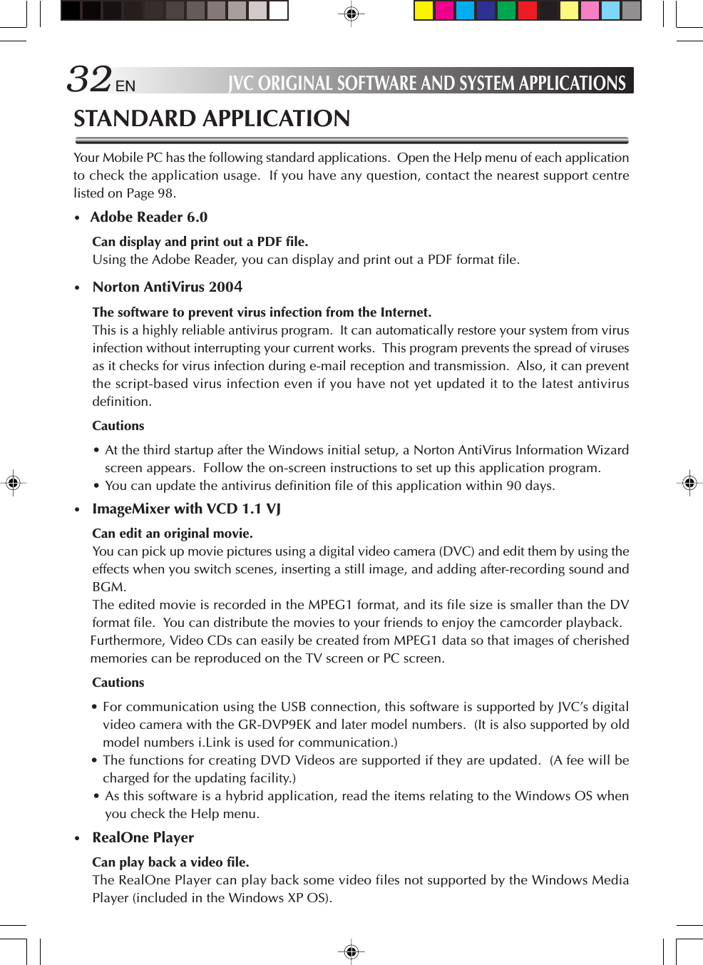
![EN 31Using Bootable CD Creator (BCDC)1. To create the removable recovery CDs using Bootable CD Creator (BCDC), connectthe DVD-ROM & CD-R/RW drive to Interlink.2. Once the DVD-ROM & CD-R/RW drive has been recognized, click [Start] [ [AllPrograms] [ [BCDC SE] to start BCDC.3. Select the writing speed, and press the “Create Recovery CD” button.4. The “Once you have successfully created Restore CD, Create Restore CD function isno longer available. Continue?” message now appears. Select “Yes.”5. The number of CD-R discs required is displayed. When the CD-R discs have beenreadied, click “OK.”6. When the “3 blank CD-R/RW media are required. Continue?” message appears,insert one of the CD-R discs into the drive, and press OK.(The screen on which the blank CD automatic execution is selected may appear. If itdoes, cancel it.)7. Data writing now starts. The “3 blank CD-R/RW media are required. Continue?”message will appear again so replace the disc in the drive. In this way, the procedurefor creating the recovery CDs is completed.](https://usermanual.wiki/ASUSTeK-Computer/J3NWM3B2200/User-Guide-404501-Page-31.png)
![34 ENTo Set Up the Standard Applications AgainYou can set up the standard applications using the Application CD-ROM. (The optionalCD-ROM drive is required.)If you have erroneously deleted any of the standard applications, you can reinstall it from theApplication CD-ROM. For details, see the “readme.txt” file in the Application CD-ROM.Warning•Use the standard CD-ROMs only on the CD-ROM drive. Otherwise, yourears or speaker system may be damaged due to loud noise.To Uninstall a Standard ApplicationUse the following procedure to uninstall a standard application program.1. Click the [start] button, then [Control Panel].2. Click the [Add or Remove Programs] icon.The programs currently installed are listed.3. Click an application program you want to uninstall. Click the [Change/Remove]button.4. When you see a “Are you sure you want to remove ...?” message, click [Yes].5. The uninstaller will remove the selected application program.JVC ORIGINAL SOFTWARE AND SYSTEM APPLICATIONS](https://usermanual.wiki/ASUSTeK-Computer/J3NWM3B2200/User-Guide-404501-Page-34.png)

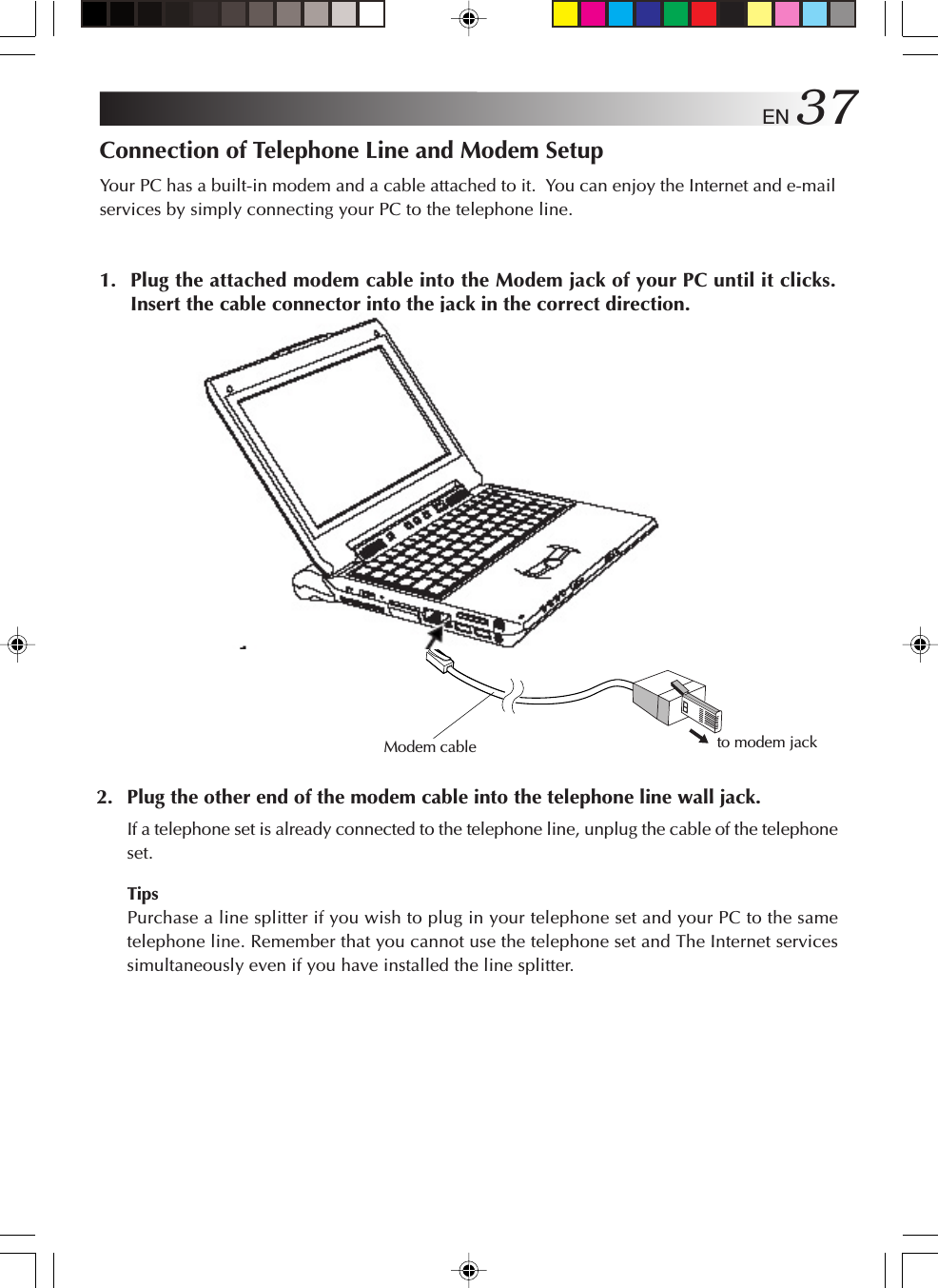
![38 EN3. Seting up the modem1Click [start] and [Control Panel] in this order.2Click [Printers and Other Hardware].3Click [Phone and Modem Options].4When the “Location Information” screen appears, enter a city code in the “area code”field. Usually, enter your city code here.Enter the phone company ID number and extension number as necessary. (They areusually not required.)5Check the dialing type of your telephone line, and select it correctly.6Click [OK], and the “Location Information” screen will close. Modem setup will becomplete.NAVIGATE IN THE INTERNET WORLD!](https://usermanual.wiki/ASUSTeK-Computer/J3NWM3B2200/User-Guide-404501-Page-38.png)
![EN 39The Internet Connection SetupUse the following procedure to connect your PC to the Internet network. This setup exampleuses the built-in modem of your PC and Microsoft’s Internet Explorer (IE) for the Internetconnection. If you have already contracted with a provider, you can manually set up the Internetconnection using the following procedure.TipsAs your PC has networking functions, you can connect it to the Internet via the network. For thesetup procedure, when you connect to the Internet via a network, see Page 63.1. Click [start] and then click [Internet] in the upper left part of the Menu.The “Welcome to the New Connection Wizard” screen will appear.TipsIf the “Welcome to the New Connection Wizard” screen does not appear, click the [start] buttonand select [All Programs], [Accessories], [Communications] to start [New connection wizard].2. Click [Next].The “Network Connection Type” screen will appear.](https://usermanual.wiki/ASUSTeK-Computer/J3NWM3B2200/User-Guide-404501-Page-39.png)
![40 EN3. Click [Connect to the Internet] option, and click [Next].The “Getting Ready” screen will appear.4. Click [Set up my connection manually] option, and click [Next].The “Internet Connection” screen will appear.5. Click [Connect using a dial-up modem] option, and click [Next].The “Connection Name” screen will appear.6. Enter the “ISP name” and click [Next].The “Phone Number to Dial” screen may appear.TipsIt is convenient to use the contracted provider name as the ISP name.NAVIGATE IN THE INTERNET WORLD!](https://usermanual.wiki/ASUSTeK-Computer/J3NWM3B2200/User-Guide-404501-Page-40.png)
![EN 417. Enter the phone number, and click [Next].The “Internet Account Information” screen will appear.8. Enter the User name and Password (and enter the password again for confirmation),and click [Next].The “Completing the New Connection Wizard” screen will appear.9. Click [Finish]. The setup for connection wizard is complete.](https://usermanual.wiki/ASUSTeK-Computer/J3NWM3B2200/User-Guide-404501-Page-41.png)
![42 ENTipsIf you need to set up the DNS server address, follow steps 10 to 20.You may need to set up DNS server addresses (the primary and secondary DNS addresses)for some providers. If the DNS server addresses are stated on the documents sent from yourprovider, you need to set them up. If not specified, you need not set these addresses.10. Click [start] and [Control Panel] in this order.The “Pick a category” screen of the Control panel will appear.11. Click [Network and Internet Connection] icon.The “or pick a Control Panel icon” screen will appear.12. Click [Network Connections].The ISP name you have set in Step 6 is shown in the “Dial-up” tag.13. Double Click the dialup connection icon. [Connect ***] screen will appear.14. Click [Properties].The “Dial-up Connection Properties” screen will appear.NAVIGATE IN THE INTERNET WORLD!](https://usermanual.wiki/ASUSTeK-Computer/J3NWM3B2200/User-Guide-404501-Page-42.png)
![EN 4315. Click [Networking].16. Click [Internet Protocol (TCP/IP)] and click [Properties].The “Internet Protocol (TCP/IP) Properties” screen will appear.17. Click [Obtain an IP address automatically], click [Use the following DNS serveraddresses], and enter the DNS server address printed on the document sent fromthe provider.18. After you have entered the addresses, click [OK].19. Respond with [OK] to the “Dial-up Connection Properties”.20. Click [x] at the upper right corner of the “Network Connection” screen.All screens will close and the Internet connection is complete.](https://usermanual.wiki/ASUSTeK-Computer/J3NWM3B2200/User-Guide-404501-Page-43.png)
![44 ENConnecting to the InternetAfter you have completed the “The Internet Connection Setup” procedure (pages 39 to 43), youcan connect to the Internet. Use the following procedure.1. Click [start] and click [Internet] at the upper left part of the Menu.The Internet Explorer will start up and the “Dial-up Connection” screen will appear. If the“Dial-up Connection” does not start, use the following steps.1Click [start] and right click [Internet] at the left upper end of the Menu. Then, select[Internet Properties].2Click the [Connections] tab and make sure that the ISP name (you have created in Step 6“The Internet Connection Setup” on page 40) has been set to default in the [Dial-up andVirtual Private Network settings]. If not set as default, select the ISP and click [Set Default].3Click [Always dial my default connection], and click [OK].2. Click [Connect].The dialup connection process will start and your PC will be connected to the Internet.TipsWhen your PC is connected to the Internet, the icon appears in the Task trayat the bottom right corner of the desktop screen.NAVIGATE IN THE INTERNET WORLD!](https://usermanual.wiki/ASUSTeK-Computer/J3NWM3B2200/User-Guide-404501-Page-44.png)
![EN 45Disconnection from the InternetWhen you are connected to the Internet, the use of the telephone line and the access to theprovider are charged.Disconnect your PC from the Internet in one of the following ways when you are finished usingthe Internet.•Double-click the task tray connection icon at the bottom right corner of the desktopscreen. When the “Auto Disconnect” dialog box appears, click [Disconnect Now].•Quit the Microsoft’s Internet Explorer (IE). When the “Auto Disconnect” dialog box appears,click [Disconnect Now].](https://usermanual.wiki/ASUSTeK-Computer/J3NWM3B2200/User-Guide-404501-Page-45.png)
![46 ENAccessing a Web PageThere is a large number of Web sites available. You can access a Web site using Microsoft’sInternet Explorer in your PC. The following shows three typical ways you can use to access aWeb site.Before starting the following steps, connect your PC to the Internet using the “Connecting tothe Internet” procedure on Page 44.When Microsoft’s Internet Explorer is active, you can access a Web site in one of the followingways.1. Directly enter the URL in the address bar.2. Jump to the destination link.3. Click [Favorites] and select Call a Web site from the Favorites.Method 1Method 2Method 3NAVIGATE IN THE INTERNET WORLD!](https://usermanual.wiki/ASUSTeK-Computer/J3NWM3B2200/User-Guide-404501-Page-46.png)
![EN 47E-MAILINGYou need to set up a mailing software to send and receive E-mails.Setting Up E-Mail SoftwareSet up the E-mail transmission using the Outlook Express installed on your PC.TipsIt is convenient for E-mail setup if you have the document sent from the provider to hand.1. Click [start] and click [E-mail] on the Menu.Outlook Express will start and the “Internet Connection Wizard” screen will appear.2. Enter the name you wish to display in the “Display name” and click [Next].The “Internet E-mail Address” screen will appear.](https://usermanual.wiki/ASUSTeK-Computer/J3NWM3B2200/User-Guide-404501-Page-47.png)
![48 EN NAVIGATE IN THE INTERNET WORLD!3. Enter your E-mail address in the “E-mail address” field, and click [Next].The “E-mail Server Name” screen will appear.4. Enter the “Incoming mail server” and “Outgoing mail server”, and click [Next].Usually select “POP3” as the “My incoming mail server is a server.” but youcan change it if necessary.The “Internet Mail Logon” screen will appear.](https://usermanual.wiki/ASUSTeK-Computer/J3NWM3B2200/User-Guide-404501-Page-48.png)
![EN 495. Enter the “Account name” and “Password,” and click [Next].The “Congratulations” screen will appear.6. Click [Finish].The “Congratulations” screen will close, and Outlook Express will start up.The setup for the E-mail software is complete.7. To quit Outlook Express, click [x] at the upper right corner of the screen.](https://usermanual.wiki/ASUSTeK-Computer/J3NWM3B2200/User-Guide-404501-Page-49.png)
![50 EN NAVIGATE IN THE INTERNET WORLD!Sending and Receiving E-mailsYou can create and send E-mail messages, and receive and read E-mail from others. You canlearn procedures to enjoy E-mailing. Use Outlook Express installed on your PC for E-mailtransmission.1. Click [start] and click [E-mail] on the Menu.Outlook Express will start.2. Click [Create a new Mail message] on the screen or click [Create Mail] in thetoolbar.The “New Message” screen will appear.TipsTo minimize the access fee to the provider and the use of the telephone line, create yourE-mail messages before connecting to the Internet.Disconnect from the provider.Connect to the provider.(Create a response/returnE-mail message)TransmissionCreate Read](https://usermanual.wiki/ASUSTeK-Computer/J3NWM3B2200/User-Guide-404501-Page-50.png)
![EN 513. Create a message.Destination: Enter the receiver's E-mail address. (Enter your E-mail address first to testE-mail transmission.)Title: Enter the message title.4. Click [Send] at the left upper end of the screen to send the created message.The “Dial-up Connection” screen will appear.TipsIf you have already connected to the Internet, the “Dial-up Connection” screen is not displayedbut the message is directly sent when you click [Send].5. Click [Connect] in the “Dial-up Connection” screen to connect to the Internet.You will be connected to the Internet, and the created mail will be sent to the specifiedaddress.6. If your mail transmission is successful, try to receive E-mail. When you areconnected to the Internet, click [Send/Recv] at the left upper end of the screen.Your PC will be connected to the provider’s mail server and you can receive E-mail.Assuming you have set your E-mail address correctly in Step 3, you can now receive the testE-mail you have sent to yourself.TipsIf message “You are currently working offline. Would you like to go online now?” appearswhen you have clicked [Send] or [Send/Recv], respond with [Yes].Enter the E-mail addressEnter the message titleEnter the message text here](https://usermanual.wiki/ASUSTeK-Computer/J3NWM3B2200/User-Guide-404501-Page-51.png)
![52 EN NAVIGATE IN THE INTERNET WORLD!7. To check the received messages, click [Inbox] on the screen.The received E-mail messages will be displayed.8. To quit Outlook Express, click [x] at the upper right corner of the screen.Cautions•Disconnect your PC from the Internet after you have transmitted E-mail and finishedaccessing a Web site.• It may not be possible to send mail properly using a company network or roamingservice. If this problem arises, the method below may solve it.Before sending the mail, first perform the receive mail operation even if no mail hasbeen received, and then click [Send].](https://usermanual.wiki/ASUSTeK-Computer/J3NWM3B2200/User-Guide-404501-Page-52.png)

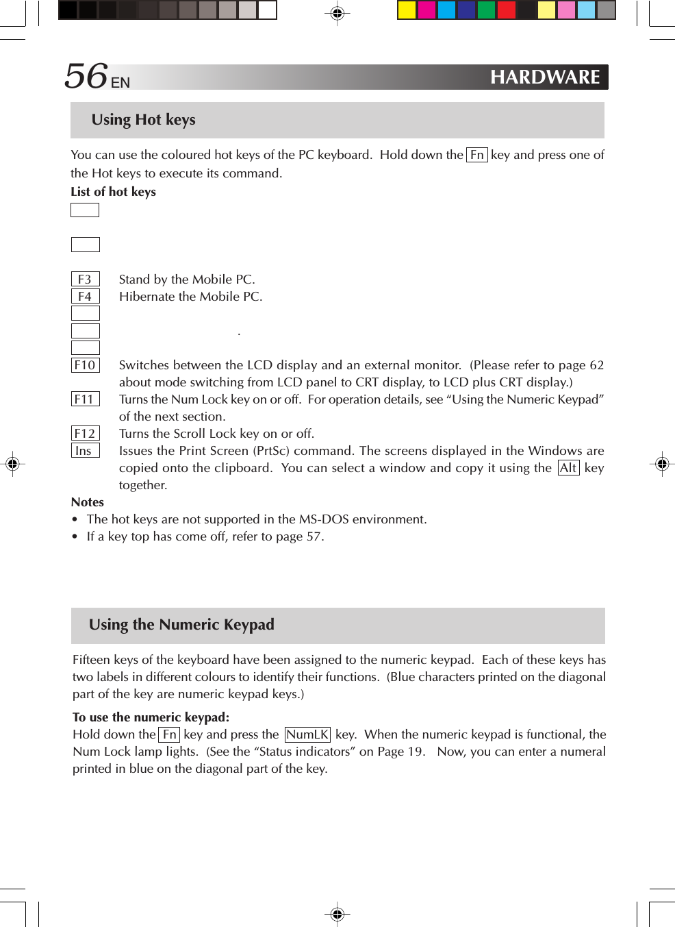
![54 ENUsing the Pointing DeviceThe pointing devices allow you to move the mouse pointer on the screen. You can move thecursor using the centre stick and three buttons in the similar way as the mouse.•Stick operationsUsually operate the stick using your index finger. The mouse pointer moves in the directionyou press the stick. You can adjust the pointer moving speed by controlling the power topress. You can control the speed of mouse pointer movement by changing the pressure to thestick.When you press the stick harder, the mouse pointer moves more quickly.Notes•If you press the stick slightly and move the pointer slowly for several seconds, the pointermay return backward. This is not a fault.•Two stick caps are included in the PC accessory pack. When the cap has deteriorated,replace it with a new one.•How to press the buttonsUsually press the three buttons using your thumb.•ClickPress the mouse left button once and release it immediately.Use this operation to select a menu option or to press the [OK] or [Cancel] button.•Right clickPress the mouse right button once.Use this operation to display a popup menu (called the shortcut).Mouse pointerLeft buttonScroll buttonRight buttonStickHARDWARE](https://usermanual.wiki/ASUSTeK-Computer/J3NWM3B2200/User-Guide-404501-Page-54.png)

![EN 61 Checking the Additional Memory BoardUse the following procedure to check the memory board installation.1. Turn on your PC and start Windows.2. Click [start] and select [Control Panel].3. Click the [Performance and Maintenance] icon.4. Click the [System] icon.The “System Properties” screen will appear.5. The total amount of memory appears on the screen.•When a memory board has been added, the number indicated by the * location increases.NoteThe size of the video memory (assigned size) is automatically assigned from the main memoryto between 8MB and 64MB depending on the PC’s operating conditions. For this reason, itcannot be changed manually.Checking here (*)](https://usermanual.wiki/ASUSTeK-Computer/J3NWM3B2200/User-Guide-404501-Page-61.png)
![EN 63Connecting to a NetworkWith the network function, you can connect to a network at your office or home to transfer databetween PCs and access the Internet from multiple PCs. For setting for intranet connection,consult a system administrator at your company. Connection to a network requires the followingitems.• LAN cable• Communication devices including a hub or routerImportantLAN cables are available in straight and cross types. Use a cable of the correct type for yourLAN environment.You must contract with an Internet service provider.Using a LAN cable, connect the LAN connector on the unit with a communication device (hubor router).See the following for setting. Setting for Network Connection•Setting the IP address manuallyImportantThis PC will acquire the necessary initial settings automatically. When you use this PC ina home network environment and the IP address is assigned automatically, the followingsteps are not necessary.1 Click the [start] button and [Control Panel].2 Click the [Network and Internet Connections] icon.3 Click the [Network Connections] icon. The “Network Connections” screen will appear.](https://usermanual.wiki/ASUSTeK-Computer/J3NWM3B2200/User-Guide-404501-Page-63.png)
![64 EN4Double-click [Local Area Connection].The “Local Area Connection Status” screen will appear.5Click the [Properties] button.The “Local Area Connection Properties” screen will appear.6On the [General] tab, double-click [Internet Protocol (TCP/IP)].The “Properties of Internet Protocol (TCP/IP)” screen will appear.7Enter appropriate values in the [Use the following IP address] and [Use the followingDNS server addresses] fields.8Click the [OK] button to save the setting.•Setting a computer name or work groupTipsTo share data or a printer among a group of computers, you must set the computers in thesame work group. This enables you to transfer data between computers.1 Click the [start] button and [Control Panel].2 Click the [Performance and Maintenance] icon.3 Click the [System] icon.The “System Properties” screen will appear.4Click the [Computer Name] tab.5Click the [Change] button.6Change the “Computer name”and/or “workgroup” as necessary.7Click the [OK] button to save the setting.The “Change in computer name” screen containing the “Welcome to the ***workgroup.” message will appear.HARDWARE](https://usermanual.wiki/ASUSTeK-Computer/J3NWM3B2200/User-Guide-404501-Page-64.png)
![EN 658Click the [OK] button.A message prompting you to restart the computer will appear.9Click the [OK] button to make the change take effect.0Restart the computer.•Checking the MAC addressUse the following procedure to check the MAC address of the internal LAN card.ImportantTo check the MAC address, you have to set a LAN (local area) connection in the [Networkconnection] screen.1Click the [start] button and [Control Panel].2Click the [Network and Internet Connections] icon.3Click the [Network Connections] icon.With the correct LAN connection, the following screen will appear.4Check that [Local Area Connection] is enabled.TipsIf it is disabled, move the mouse pointer to [Local Area Connection] and press the rightmouse button to bring up a menu, click [Enable] to enable the connection.](https://usermanual.wiki/ASUSTeK-Computer/J3NWM3B2200/User-Guide-404501-Page-65.png)
![66 EN5Double-click [Local Area Connection].The “Local Area Connection Status” screen will appear.6Click the [Support] tab and the [Details] button.The “Network Connection Details” screen will appear.7The MAC address is displayed as the “Physical Address” on the list.HARDWARE](https://usermanual.wiki/ASUSTeK-Computer/J3NWM3B2200/User-Guide-404501-Page-66.png)
![EN 67Network Connections Using a Wireless LANThe model MP-XP731GB PC comes with wireless LAN functions.You can connect to a LAN system from any location within the wireless communication area toaccess the Internal LAN or send and receive mail. By using a wireless LAN access point (availablefrom a retail store) which is connected to an ADSL modem (available from a retail store), you canaccess broadband environments from a multiple number of PCs. Furthermore, you can bringyour PC to one of the public wireless LAN services which have been increasing of late and enjoyaccessing the Internet by wireless means.For the wireless network settings and details, refer to [Help and Support] on the [Start] menu.General Description of Wireless LANThe wireless LAN in this PC supports the following functions.•Automatic communication speed selection function: 11, 5.5, 2 and 1 (Mbps)•Frequency channel selection : All 11 channels (2412 to 2462 MHz)•Roaming between multi-channels•Power management function•Compliance with IEEE802.11 and IEEE802.11b standardsTypes of Wireless LAN Networks•AdHoc ModeIn this mode, the data is transferred directly between PCs. It is suited to wireless networks inwhich data is transferred between several laptops. The peer-to-peer workgroup setting forproviding equal handling for all the laptops is established.•Infrastructure ModeIn this mode, the PCs are connected through an access point. If the access point is connectedto an ADSL, CATV, ISDN or other such line, the PCs can be connected to the Internet as well.XV841/g](https://usermanual.wiki/ASUSTeK-Computer/J3NWM3B2200/User-Guide-404501-Page-67.png)
![EN 691. Start up the PC.If the [Intel(R) Setting Service] screen appears, click the [No] button.This message will no longer appear if a check mark is entered for “Do not displayin the future” .2. Set the wireless LAN to ON using the wireless LAN ON/OFF switch.The wireless LAN now starts up, and the wireless LAN indicator above theF10 key flashes while a search is being conducted, and it lights when aconnection is made.(In order to prevent other electronic devices or equipment in places such asaircraft and hospitals from being adversely affected, keep the wireless LANfunctions shut down when starting up the PC or restoring its operation from thestandby or hibernation mode.)3. Set the IP address to be used by the wireless LAN.This step must be taken only when the wireless LAN is to be used for the first time.Once the wireless LAN has been successfully connected, jump to step 4 (page 72)when re-connecting the wireless LAN for the second or any subsequent time.1Double-click the [Wireless Network Connection] icon on the task tray.The [Wireless Network Connection] screen now appears.](https://usermanual.wiki/ASUSTeK-Computer/J3NWM3B2200/User-Guide-404501-Page-69.png)
![70 EN HARDWARE2Click the [Properties] button on the [Wireless Network Connection] screen.The [Wireless Network Connection Properties] screen now appears.3Click the [General] tab on the [Wireless Network Connection Properties] screen, andclick [Internet Protocol (TCP/IP)] to select the Internet protocol. A screen such as the oneshown below appears.](https://usermanual.wiki/ASUSTeK-Computer/J3NWM3B2200/User-Guide-404501-Page-70.png)
![EN 714Click the [Properties] button on the [Wireless Network Connection Properties] screen.The [Internet Protocol (TCP/IP) Properties] screen shown below now appears.5Use the following example as a reference, and proceed with the settings to suit how thewireless LAN is to be used.For making a wireless network connection using a public wireless LAN service:With a public wireless LAN service, it is customary for the DHCP server function thatautomatically allocates the IP address to be enabled. On the [Internet Protocol (TCP/IP)Properties] screen, click and select “Obtain an IP address automatically” and “ObtainDNS server address automatically” and click the [OK] button.For directly communicating with another PC using a peer-to-peer connection:Set the IP address which has the same network address as the IP address of the PC thatserves as the other end of the communication. If, for example, the IP address at the otherend is 192.168.1.1, click and select “Use the following IP address” on the [Internet Protocol(TCP/IP)] screen, and input 192.168.1.2, for instance, in the “IP address” field. Input255.255.255.0 for “Subnet mask” and click the [OK] button.](https://usermanual.wiki/ASUSTeK-Computer/J3NWM3B2200/User-Guide-404501-Page-71.png)
![72 EN HARDWAREFor making the wireless network connection via an access point:In cases involving an in-company LAN, etc. where a DHCP server is in operation on thewired network to which the access point is connected, click and select “Obtain an IPaddress automatically” and “Obtain DNS server address automatically” on the [InternetProtocol (TCP/IP) Properties] screen, and click the [OK] button. (Check with a networkadministrator to ascertain whether the DHCP server is in operation.)In a home or other such environment where a DHCP server is not in operation, manuallyset the IP address to the one that has the same network address as the IP address of theaccess point. If, for example, the IP address of the access point has been set to 192.168.10.1,click and select “Use the following IP address” on the PC’s [Internet Protocol (TCP/IP)Properties] screen, and input 192.168.10.2, for instance, in the “IP address” field. Input255.255.255.0 for “Subnet mask” and click the [OK] button.When connecting to the Internet using a wireless LAN access point connected to an ADSLmodem (available from a retail store), check the method used to set the IP address withthe Internet service provider.4. When the wireless LAN starts up, the PC automatically searches for thenetwork which can be used. When a usable network has been detected,a message appears on the task tray.5. Double-click the wireless network connection icon on the task tray atthe bottom right of the screen.The [Wireless Network Connection] screen appears.6. Select the access point to be connected from the ones in “Availablewireless networks”, and click the [Connect] button.](https://usermanual.wiki/ASUSTeK-Computer/J3NWM3B2200/User-Guide-404501-Page-72.png)
![74 EN HARDWAREHow to Set the Wireless LAN Function1. Double-click the [Wireless Network Connections] icon on the task tray.The “Wireless Network Connection Status” screen will appear.2. Click the [Properties] button on the [Wireless Network Connection Status]screen.The [Wireless Network Connection Properties] screen will appear.3. Click the [Wireless Networks] tab on [Wireless Network ConnectionProperties] screen.](https://usermanual.wiki/ASUSTeK-Computer/J3NWM3B2200/User-Guide-404501-Page-74.png)
![EN 754. Select the network used from the list of [Preferred Networks], and clickthe [Properties] button.5. Set the necessary items, and click the [OK] button.Example 1) Set [Data encryption] to [WEP].2) Remove the check from the “The key is provided automatically” item.3) Input the “Network key.” (Verification input included)With 64-bit WEP, a key consisting of up to five half-size alphanumerics (or10 characters in the hexadecimal format) may be input.With 128-bit WEP, a key consisting of up to 13 half-size alphanumerics (or26 characters in the hexadecimal format) may be input.4) Select “Key index.”6. Close all screens. This completes the settings.](https://usermanual.wiki/ASUSTeK-Computer/J3NWM3B2200/User-Guide-404501-Page-75.png)
![76 ENChecking the Battery LevelOn the “Power Option Properties” screen, click the [Power Meter] tab. The current total batterylevel is displayed. Use the following procedure.1. Click the [start] button and [Control Panel].2. Click the [Performance and Maintenance] icon.3. Click the [Power Options] icon.The [Power Option Properties] screen will appear.4. Click the [Power Meter] tab.Battery gauges #1 (built-in battery) and #2 (external battery), and the total level of these twobatteries are displayed.Important•Battery gauge #2 (external battery) is displayed only when a standard lithium ion batterypack or large-capacity lithium ion battery pack is used.•Note that the external battery is consumed first.HARDWARE](https://usermanual.wiki/ASUSTeK-Computer/J3NWM3B2200/User-Guide-404501-Page-76.png)
![EN 77Power-saving ModeIn compliance with the operation regulations of the International Energy Star Program, this unitenters the power-saving mode when no operation is performed for a certain period.On the [Power Schemes] tab in the “Power Option Properties” screen (page 76), you can specifythe time that must expire before the unit enters the power-saving mode. The table below showsthe factory settings.Operating onAC powerStatus1Turn off monitor: 15 minutes 5 minutes2Turn off hard disks: 30 minutes 5 minutes3System standby: 20 minutes 5 minutes4System hibernates: 3 hours 2 hoursThe LCD screen turns off.The (Stand By) lamp is still lit in green.The hard disk power is turned off withthe LCD screen kept off.The (Stand By) lamp is still lit in green.The PC stores the current system statuson the hard disk.The (Stand By) lamp will go out.The LCD screen is turned off.The (Stand By) lamp flashes in green.TipsTo exit status 1 or 2 , move the stick or press any key on the keyboard.To exit status 3 , press the Power key or any key on the keyboard.To exit status 4 , press the Power key. Important•In statuses 1 through 3, Windows is still running. Note that the current condition islost if the PC is turned off by pressing the Power key for more than 4 seconds.Operatingon battery](https://usermanual.wiki/ASUSTeK-Computer/J3NWM3B2200/User-Guide-404501-Page-77.png)


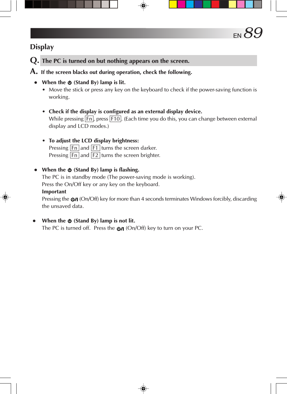
![EN 87Startup and Operation of WindowsQ. The screen has hung.A. Use the following procedure to forcibly exit the applications running on your PC.ImportantWhen applications are forcibly terminated through this procedure, any unsaved unsaveddata will be lost.Terminating an application forcibly1. While holding down the [Ctrl] and [Alt] keys, press the [Del] key once.The “Windows Task Manager” screen will appear.2. Click the [Applications] tab.3. Click the application that hung, then [End Task]. In most cases, applications that havehung are indicated as “Not Responding.”4. When a confirmation message for terminating the application appears, click [End Now].5. Click [x] on the Windows Task Manager screen.TipsWhen the application cannot be terminated, forcibly restart Windows. To restart Windowsforcibly, start Windows Task Manager, click [Shut Down] on the toolbar, then click [Restart].If your PC does not restart through the above procedure, press the RESET button on theside of the unit (page 12) or keep pressing the Power key for 4 seconds or longer to turnoff the power.About the message appearing if Windows is not exited normallyIf you turn off the power without terminating Windows, the “Checking file system on c:”message appears at the next Windows startup, Windows and hard disk conditions will bechecked, and data will be restored as necessary.](https://usermanual.wiki/ASUSTeK-Computer/J3NWM3B2200/User-Guide-404501-Page-87.png)
![88 EN TROUBLESHOOTINGQ. If the system fails to start up when I have tried to start it up with a USB deviceconnectedA. Disconnect the connected USB device, start up the system, and then re-connect the device.Q. Starting the PC in the safe modeA. If some kind of trouble occurs on the PC, use the safe mode where the PC starts up withminimum functions.Use the following procedure to start up your PC in the safe mode.1. Turn on the PC.2. As soon as the JVC logo appears, hold down the F8 key.TipsIf the F8 key is pressed too late, Windows tries to make a normal startup.Restart your PC and go back to step 2.3. Select [Safe Mode] and press Enter .4. Check that the operating system is selected on the “Please select the operating system tostart:” screen. Press Enter .5. When you see the “To begin, click your user name” message, click an account withwhich you want to start the PC in the safe mode.6. Clicking [Yes] starts your PC in the safe mode.Q. If Windows will not startA. When “Power On Self Test” is carried out at the time of power on and something wrong orout of order is detected, an error code (2 digits) is indicated on the screen, and start-up issuspended.If you think that Windows will not start confirm whether an error code is indicated on thescreen. When you ask for service, please report this error code to the service centre.An error code may not always be indicated dependent on the cause of the trouble.](https://usermanual.wiki/ASUSTeK-Computer/J3NWM3B2200/User-Guide-404501-Page-88.png)
![90 EN TROUBLESHOOTINGUsing the InternetQ. I cannot dial up.A. Check the connection. •Check that the modem cable is connected.If you see the “There was no dial tone.” message, check the connection between the unitand the telephone line connector on the wall. Insert the modem fully until it is locked. • When a divider is usedConnect the modem cable directly to the phone jack for checking. •When you are connecting via an ISDN lineCheck that the terminal adapter is ready.For details, refer to the instruction manual for your terminal adapter. •Check that the modem is recognized properly.1. Click the [start] button and [Control Panel].2. Click the [Printers and Other Hardware] icon.3. Click the [Phone and Modem Options] icon, then the [Modems] tab.4. Select the modem by clicking it, click [Properties], then the [Diagnostics] tab.5. Click [Query Modem].When the modem is recognized properly, the inquiry command and response to it willbe displayed.ImportantIf the modem is not recognized properly, check if it conflicts with any other device.If the modem device is displayed with a “!” mark on the Device Manager screen, it mayconflict with another device.](https://usermanual.wiki/ASUSTeK-Computer/J3NWM3B2200/User-Guide-404501-Page-90.png)
![EN 91Q. The PC dials but connection is not established.A. Check the dialing setting. •Check that the dialing type (tone or pulse) is correctly set for your telephone line.For checking and configuration procedures, see “3. Setting up the modem” on page 38. • When no connection operation occurs, check the destination setting.Use the following procedure to check the setting for connecting to your Internet ServiceProvider (ISP) or network.1. Click the [start] button and [Control Panel].2. Click the [Network and Internet Connections] icon.3. Click the [Network Connections] icon.4. Right-click the icon for the destination of connection to bring up a pop-up menu. Click[Properties] in the menu.5. Check the setting according to the instruction manual provided from your ISP.•On the [General] tab, check the “Connect using” and “Phone number” settings.TipsSome ISPs have different phone numbers for access points via ISDN lines from thosefor points via ordinary lines. Contact your ISP for details.•For how to check and set the DNS server addresses (primary DNS and secondaryDNS), see DNS server address setting procedure (10-20) on pages 42 and 43.ImportantIf your ISP specifies no DNS server address, click [Obtain DNS server address automatically].](https://usermanual.wiki/ASUSTeK-Computer/J3NWM3B2200/User-Guide-404501-Page-91.png)
![92 ENQ. The PC makes a connection operation but connection is not established.A. Check the following.•Check the user name and password.Refer to the material sent from your ISP for correct user name and password. • The internal modem dials but negotiation is not made.The access point may have a problem. Try to establish a connection later. If this attemptfails, use a different access point. • Advice when using the internal modemIf “Max Battery” or “Presentation” has been selected for “Power Options” in the “PowerOptions”/”Power Schemes” tab from [Power Option Properties] and the battery is beingused to power the PC, this may cause the internal modem to slow down its speed ofcommunication or fail to dial up, depending on the condition of the telephone line. Incases like this, change to a setting other than “Max Battery” or “Presentation” (such as“Portable/Laptop”).Q. The PC cannot send or receive e-mail messages.A. If you are using the Outlook Express software, check the e-mail software settings.If you are using any other mailer than Outlook Express, refer to the pertinent instructionmanual or help.1. Start Outlook Express.TipsIf the “Dial-up Connection” screen appears, click [Work Offline] or the [x] button.2. Click [Tools] on the tool bar (at the top of the screen). Click [Accounts] on the Toolsmenu.3. Click the [Mail] tab.4. Click an account and [Properties].5. Click the tabs to check that the entries are correct.ImportantUse lower-case letters only.TROUBLESHOOTING](https://usermanual.wiki/ASUSTeK-Computer/J3NWM3B2200/User-Guide-404501-Page-92.png)
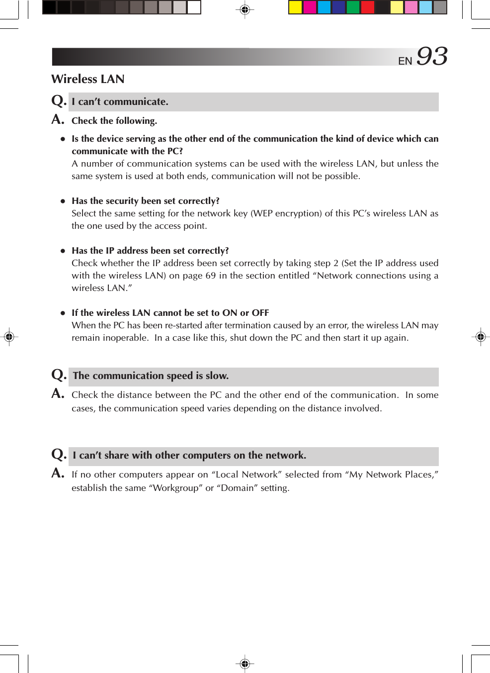
![94 ENQ. How can I check the MAC address?A. Proceed as follows to check the MAC address of the PC’s wireless LAN.*In order to check the MAC address, the wireless network connection must first be setusing [Network Connections].1. Click the [Start] menu, and click [Control Panel].2. Click the [Network and Internet Connections] icon.3. Click the [Network Connections] icon.4. Check that [Wireless Network Connections] is enabled.5. Double-click [Wireless Network Connections].The “Wireless Network Connection Status” screen appears.6. Click the [Support] tab, and click the [Details] button.The [Network Connection Details] screen appears.7. The value for “Physical address” displayed on the list indicates the MAC address.BatteryQ. The battery is not charged.A. Check the following. •When the built-in battery cannot be chargedThis PC is shipped with a short-circuiting pin on the standard lithium ion battery packterminal. Be sure to remove the pin before use.For removal, see “Mounting/Dismounting the Lithium Ion Battery Pack” on page 16. • When the standard lithium ion battery pack cannot be chargedFor how to mount the standard lithium ion battery pack, see “Mounting/Dismounting theLithium Ion Battery Pack” on page 16.If you are still unable to charge the battery pack, check the following.Check that the AC adapter is connected correctly to an appropriate power socket and thePC unit.For connection, see “4. Recharge the built-in battery pack by plugging the AC cord into DCInput connector” on page 17.Q. Battery discharge faster than expected.A. This device continues to supply DC current to the USB port in standby in order to respondto the wake-up signals from some USB peripherals.If you keep this device in standby for long time with just battery power, please removeperipherals from the USB port.TROUBLESHOOTING](https://usermanual.wiki/ASUSTeK-Computer/J3NWM3B2200/User-Guide-404501-Page-94.png)
![EN 95MiscellaneousQ. The PC is hot.A. The PC may become warm when used for a long time, but this is not a failure.Do not block the vents in the bottom or sides through which internal heat is removed.Q. The PC makes no sound.A. Check the following.•Check if the speaker is muted.To use the volume control, press Fn and F7 .(This key combination turns on and off the volume control.)Pressing Fn and F5 turns down the volume.Pressing Fn and F6 turns up the volume.Q. I forgot the password.A. If you forgot your password, you cannot start the PC again.Whenever you set a password, be careful not to forget it.•If you forget the user account (computer administrator) password1. When a password deleting disk has been preparedYou can delete the password using the disk. For how to prepare a password deleting disk,see “Help and Support Centre” from the [start] menu.2. When another computer administrator account has been createdIf an additional computer administrator (a user who has the administrator rights) is createdother than the user who forgot the password, log on to the computer as the administratorto change the password.3. When no computer administrator account has been createdWhen no administrator password is set, you can change the forgotten user password bystarting up Windows in the safe mode and logging on as an administrator.*If any of the above does not solve the problem, you must restore the factory setting. Forprocedure for setting up Windows again, see “Setting Up Your PC Again” on page 82.](https://usermanual.wiki/ASUSTeK-Computer/J3NWM3B2200/User-Guide-404501-Page-95.png)
![96 EN•If you forget the BIOS passwordThe following passwords can be set on the BIOS.•Supervisor PasswordThis is the password used by the administrator. If it has been set, it means that only anindividual who inputs this password correctly can set or change any of the items. Theuser will be asked for this password at boot-up and BIOS setup.•User passwordWhen this password is set, the user is requested to enter the password to start Windowsor change a BIOS setting.•HDD passwordThe password required for accessing the hard disk.Important•You cannot delete the BIOS password even if you forget it. To delete it forcibly, youhave to return your PC to us for chargeable service. (It may require hard disk drivereplacement.)•To bring up the BIOS menu, turn on the PC and press the Alt and F2 keys while theJVC logo screen is shown.Do not change the BIOS setting unless you have adequate knowledge of computers.A wrong setting can make your PC unable to start up again or, worse, damage it.Q. Setting procedure does not complete.A. If Internet, e-mail, or any other setting does not complete through the procedure describedin this manual, check the following.•If the [Control Panel] display is in Classical mode, change it to the Category mode. Allthe setting procedures in this manual assume the Category display mode.TROUBLESHOOTING](https://usermanual.wiki/ASUSTeK-Computer/J3NWM3B2200/User-Guide-404501-Page-96.png)