ASUSTeK Computer M3000N Dual Band Wireless LAN Card User Manual NB Copyright Eng 3 4 03 p65
ASUSTeK Computer Inc Dual Band Wireless LAN Card NB Copyright Eng 3 4 03 p65
Contents
- 1. Revised Manual
- 2. Revised Manual 01122004
- 3. Revised Manual 01122003
Revised Manual 01122004

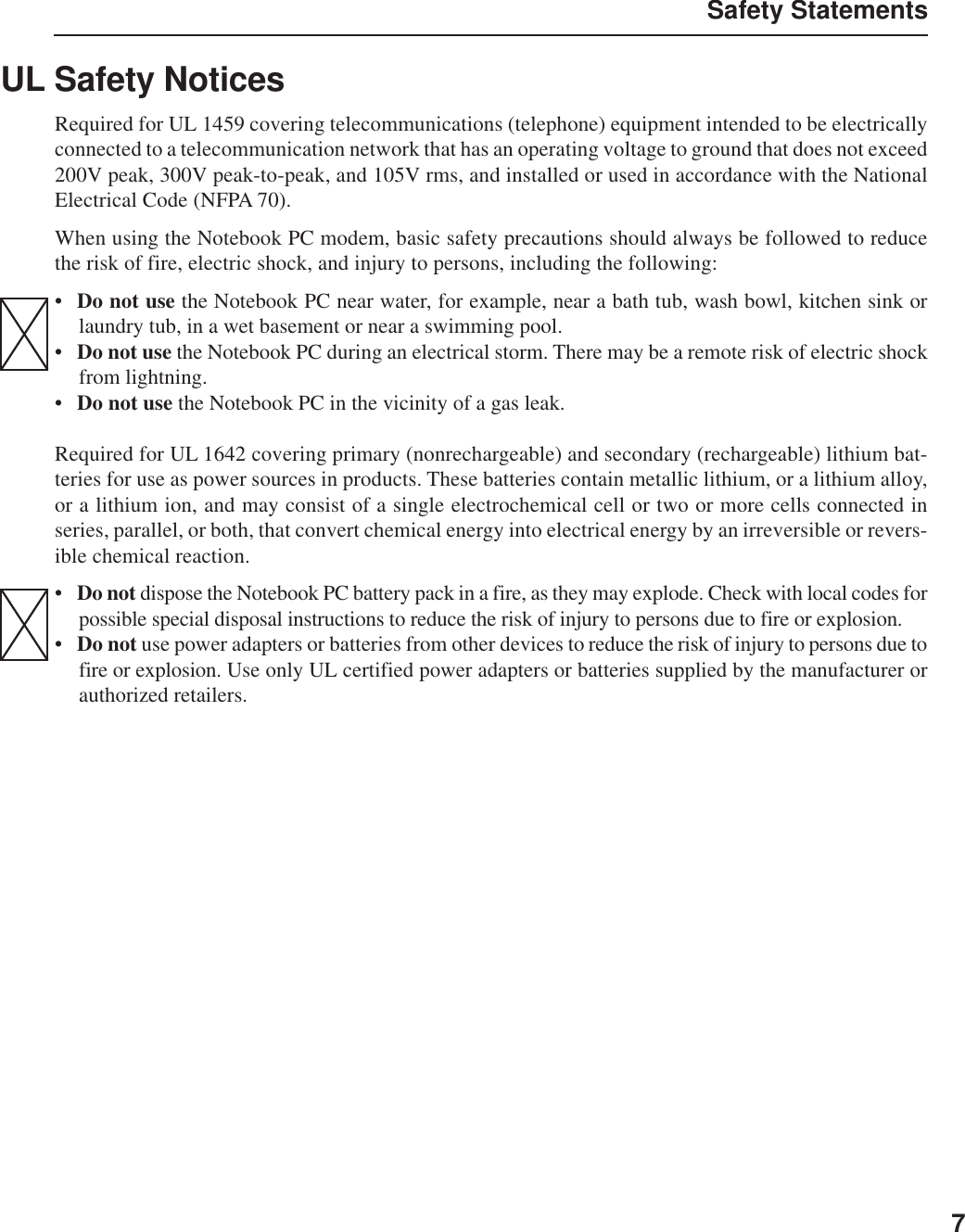
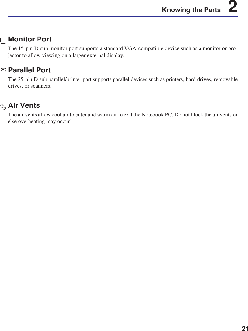
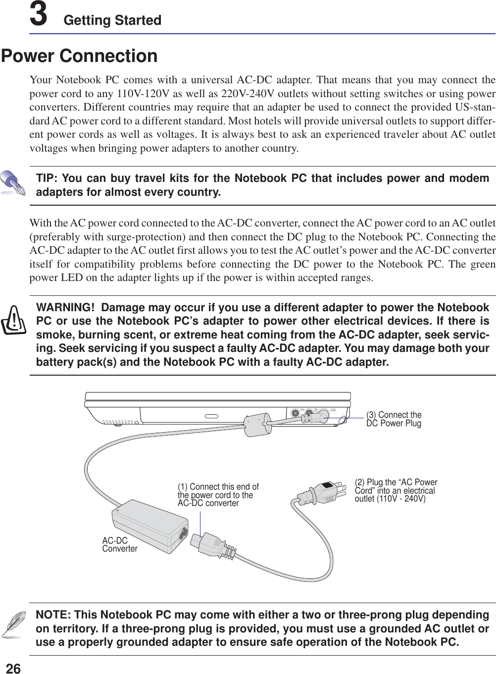
![121 Introducing the Notebook PCAbout This User’s ManualYou are reading the Notebook PC User’s Manual. This User’s Manual provides information on thevarious components in the Notebook PC and how to use them. The following are major sections of thisUser’s Manuals:1. Introducing the Notebook PCIntroduces you to the Notebook PC and this User’s Manual.2. Knowing the PartsGives you information on the Notebook PC’s components.3. Getting StartedGives you information on getting started with the Notebook PC.4. Using the Notebook PCGives you information on using the Notebook PC’s components.5. AppendixIntroduces you to optional accessories and gives additional information.Notes For This ManualThis User’s Manual was created using Macintosh versions of Adobe® PageMaker™ 6.52, Adobe®Photoshop™ 5.5, Adobe® Illustrator® 8.0, and Macromedia® Freehand™ 8.0.1. The body text type usedin this manual is “Times” (MAC) or “Times New Roman” (Windows™) and headings are “Helvetica”(MAC) or “Arial” (Windows™). A few notes and warnings in bold are used throughout this guide thatyou should be aware of in order to complete certain tasks safely and completely. These notes havedifferent degrees of importance as described below:NOTE: Tips and information to aidin completing a task.WARNING! Information to preventdamage to components, damage todata, or personal injury.CAUTION! Information on actions thatmust be avoided to prevent damage tocomponents, damage to data, or per-sonal injury.Text enclosed in < > or [ ] represents a key on the keyboard; do not actually type the <> or [ ] and the enclosed letters.TIP: Tips and useful information forpower (advanced) computer users.](https://usermanual.wiki/ASUSTeK-Computer/M3000N.Revised-Manual-01122004/User-Guide-388223-Page-13.png)


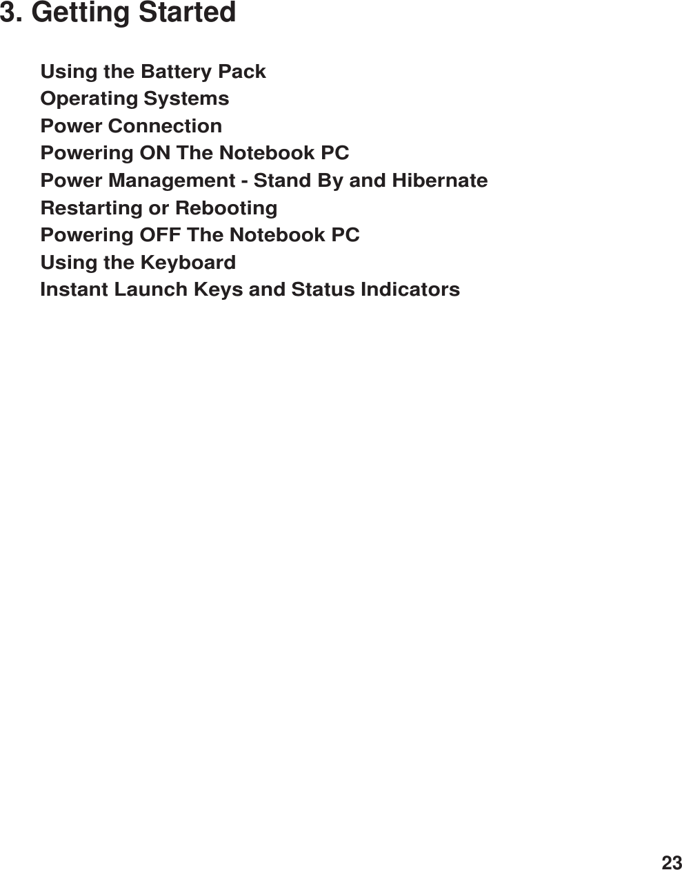
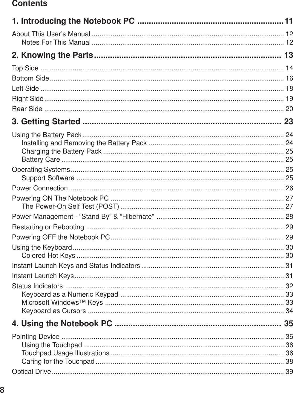
![27Getting Started 3The Power-On Self Test (POST)When you turn ON the Notebook PC, it will first run through a series of software-controlled diagnostictests called the Power-On Self Test (POST). The software that controls the POST is installed as apermanent part of the Notebook PC’s architecture. The POST includes a record of the Notebook PC’shardware configuration, which is used to make a diagnostic check of the system. This record is createdby using the BIOS Setup program. If the POST discovers a difference between the record and theexisting hardware, it will display a message on the screen prompting you to correct the conflict byrunning BIOS Setup. In most cases the record should be correct when you receive the Notebook PC.When the test is finished, you may get a message reporting “No operating system found” if the harddisk was not preloaded with an operating system. This indicates that the hard disk is correctly detectedand ready for the installation of a new operating system.The S.M.A.R.T. (Self Monitoring and Reporting Technology) checks the hard disk drive during POSTand gives a warning message if the hard disk drive requires servicing. If any critical hard disk drivewarning is given during bootup, backup your data immediately and run Windows disk checking program.To run Window’s disk checking program: (1) right-click any hard disk drive icon in “My Computer”, (2)choose Properties, (3) click the Tools tab, (4) click Check Now, (5) select a hard disk drive, (6) selectThorough to also check for physical damages, and (7) click Start. Third party disk utilities such as Symantec’sNorton Disk Doctor can also perform the same functions but with greater ease and more features.Powering ON The Notebook PCThe Notebook PC’s power-ON message appears on the screen when you turn it ON. If necessary, you mayadjust the brightness by using the hot keys. If you need to run the BIOS Setup to set or modify the systemconfiguration, press [F2] upon bootup to enter the BIOS Setup. If you press [Tab] during the splashscreen, standard boot information such as the BIOS version can be seen. Press [ESC] and you will bepresented with a boot menu with selections to boot from your available drives.WARNING! If warnings are still given during bootup after running a software diskchecking utility, you should take your Notebook PC in for servicing. Continued usemay result in data loss.NOTE: Before bootup, the display panel flashes when the power is turned ON. This ispart of the Notebook PC’s test routine and is not a problem with the display.WARNING! Never turn OFF or reset your Notebook PC while the hard disk or floppydisk is in use and the activity LED is flashing; doing so can result in loss or destruc-tion of your data. To protect the hard disk drive, always wait at least 5 seconds afterturning OFF your Notebook PC before turning it back ON.](https://usermanual.wiki/ASUSTeK-Computer/M3000N.Revised-Manual-01122004/User-Guide-388223-Page-28.png)
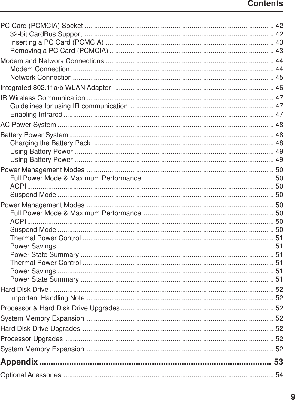
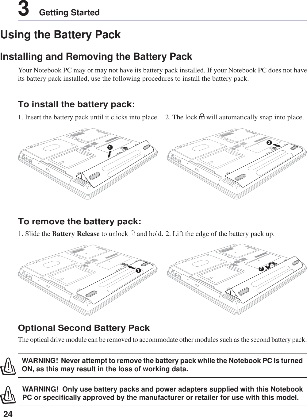
![29Getting Started 3Restarting or RebootingAfter making changes to your operating system,you may be prompted to restart the system. Someinstallation processes will provide a dialog box toallow restart. To restart the system manually:Click the Start button and select Shut Down | andchoose Restart.In case the operating system hangs (stops, freezes,crashes), try the following in this order:1. Try a “warm boot” by pressing the[Ctrl][Alt][Del] keys simultaneously. (You maytry a few times.)2. If warm booting fails to work, you can press the reset button located in a small hole on the bottom ofthe Notebook PC with a pen, mechanical pencil, or paper clip. (Do not use a standard pencil becausethe tip may break off in the hole.)Powering OFF the Notebook PCFor operating systems equipped with ACPI (Win-dows ME/2000/XP), the Notebook PC can be pow-ered OFF by using Start | Shut Down... | Shutdown. For operating systems without proper powermanagement (DOS, Windows NT), you mustpower OFF the Notebook PC by holding the powerswitch for 2 seconds (as opposed to 1 second topower ON) after closing applications and exitingoperating systems. Holding the power switch for2 seconds is necessary in order to prevent acci-dental power-OFFs.](https://usermanual.wiki/ASUSTeK-Computer/M3000N.Revised-Manual-01122004/User-Guide-388223-Page-30.png)
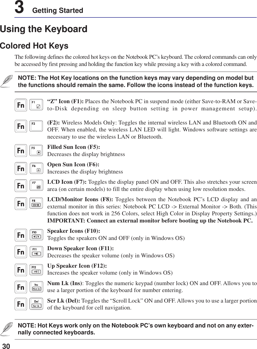
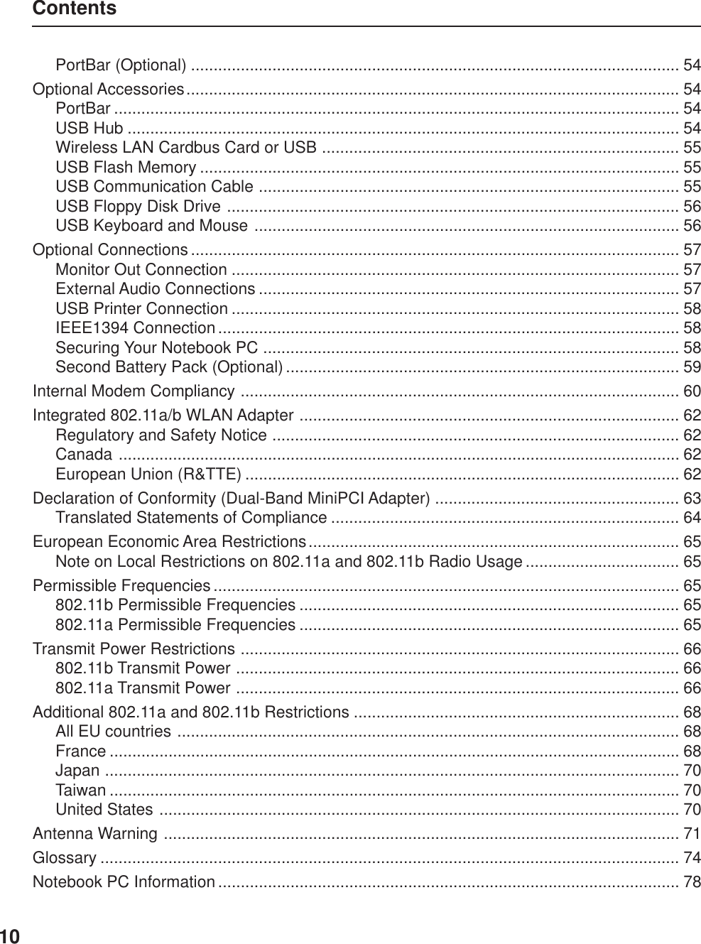
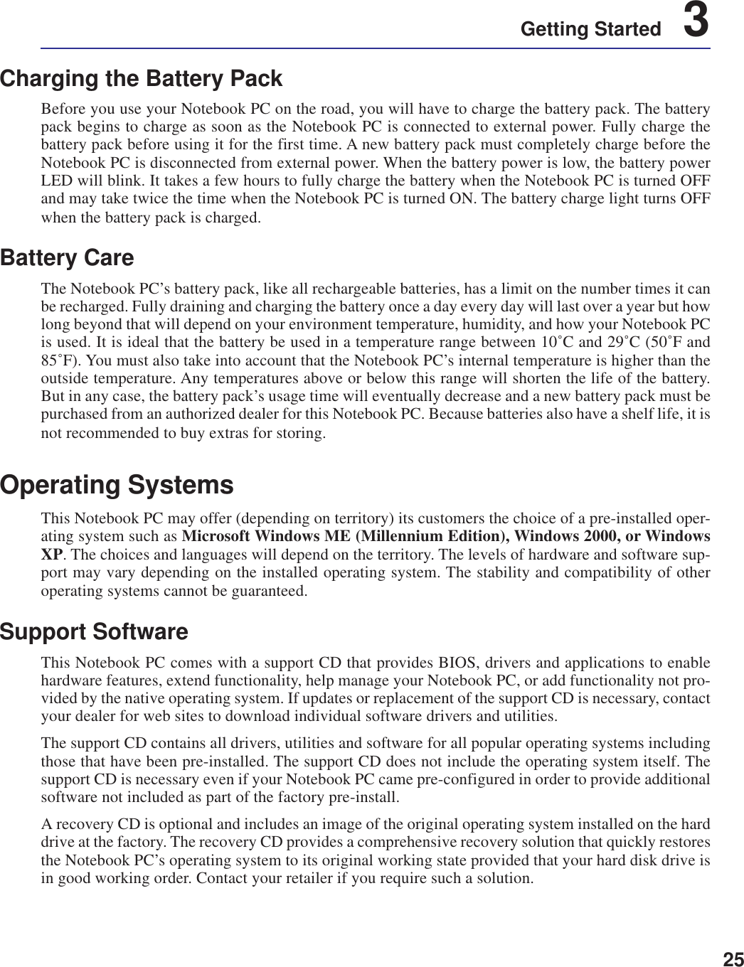
![323 Getting StartedStatus IndicatorsPower IndicatorThe green LED lights to indicate that the Notebook PC is turned ON and blink when the Notebook PCis in the Suspend-to-RAM (Standby) mode. This LED is OFF when the Notebook PC is OFF or in theSuspend-to-Disk (Hibernation) mode.Battery Charge IndicatorThe battery charge indicator is an LED that shows the status of the battery’s power as follows:ON: The Notebook PC’s battery is chargingBlinking: The Notebook PC’s battery power is lower than 10%Off: The Notebook PC’s battery is charged or completely drainedEmail IndicatorFlashes when there is one or more new email(s) in your email program’s inbox. This function requiressoftware setup and may not be currently configured on your Notebook PC. This function is designedfor Microsoft email software only and may not work with email software from other companies.Wireless LAN / Bluetooth Indicator (Optional)Flashes when there are packets transmitted or received by the internal wireless LAN or Bluetooth. ThisLED requires the optional internal wireless LAN or Bluetooth to function.Drive Activity IndicatorIndicates that the Notebook PC is accessing one or more storage device(s) such as the hard disk. Thelight flashes proportional to the access time.Number LockIndicates that number lock [Num Lk] is activated when lighted. Number lock allows some of the key-board letters to act as numbers for easier numeric data input.Capital LockIndicates that capital lock [Caps Lock] is activated when lighted. Capital lock allows some of thekeyboard letters to type using capitalized letters (e.g. A, B, C). When the capital lock light is OFF, thetyped letters will be in the lower case form (e.g. a,b,c).1ARight - Above KeyboardLeft - Above Keyboard](https://usermanual.wiki/ASUSTeK-Computer/M3000N.Revised-Manual-01122004/User-Guide-388223-Page-33.png)
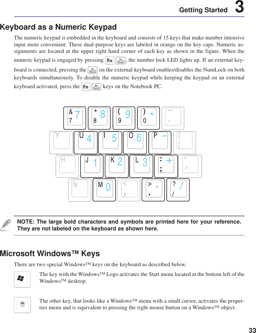
![343 Getting StartedKeyboard as CursorsThe keyboard can be used as cursors while Number Lock is ON or OFF in order to increase navigationease while entering numeric data in spreadsheets or similar applications.With Number Lock OFF, press and one of the cursor keys shown below. For example [Fn][8] forup, [Fn][K] for down, [Fn][U] for left, and [Fn][O] for right.With Number Lock ON, use [Shift] and one of the cursor keys shown below. For example [Shift][8]for up, [Shift][K] for down, [Shift][U] for left, and [Shift][O] for right.NOTE: The large bold characters and symbols are printed here for your reference.They are not labeled on the keyboard as shown here.](https://usermanual.wiki/ASUSTeK-Computer/M3000N.Revised-Manual-01122004/User-Guide-388223-Page-35.png)
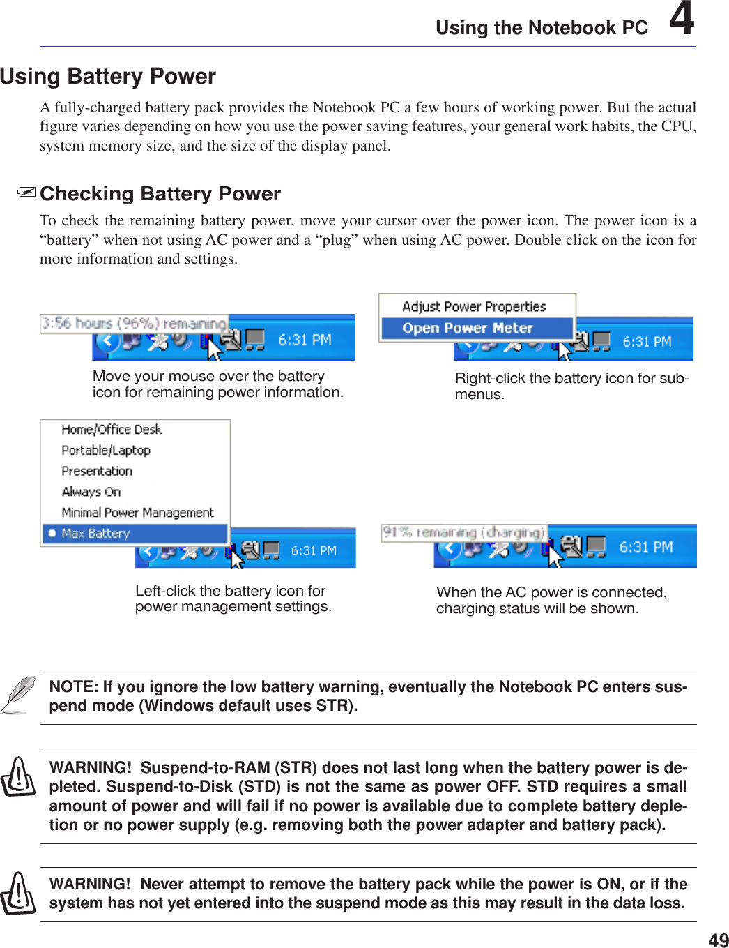
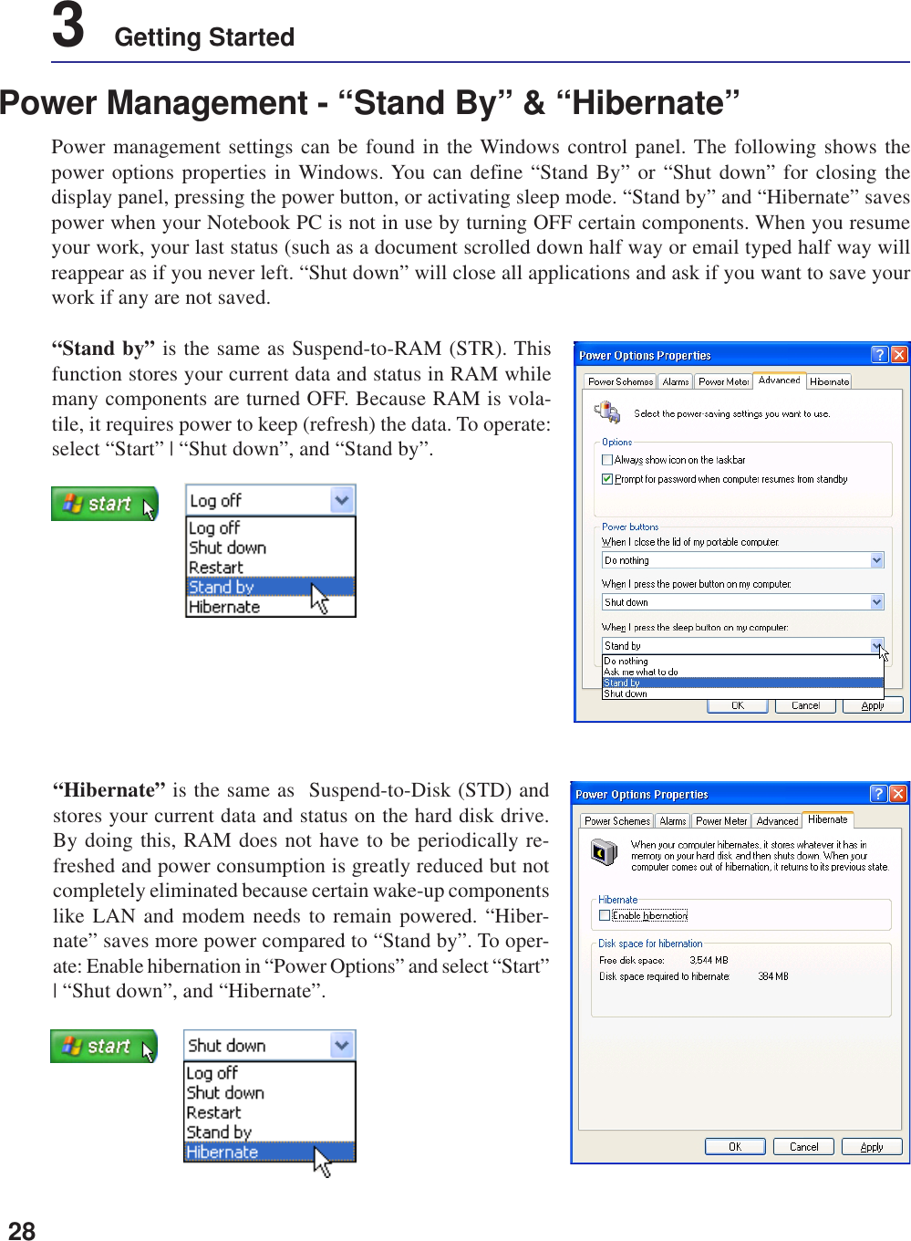
![504 Using the Notebook PCPower Management ModesThe Notebook PC has a number of automatic or adjustable power saving features that you can use tomaximize battery life and lower Total Cost of Ownership (TCO). You can control some of these fea-tures through the Power menu in the BIOS Setup. ACPI power management settings are made throughthe operating system. The power management features are designed to save as much electricity aspossible by putting components into a low power consumption mode as often as possible but also allowfull operation on demand. These low power modes are referred to as “Stand by” (or Suspend-to-RAM)and “Hibernation” mode or Suspend-to-Disk (STD). The Standby mode is a simple function providedby the operating system. When the Notebook PC is in either one of the power saving modes, the statuswill be shown by the following: “Stand by”: Power LED Blinks and “Hibernation”: Power LED OFF.Full Power Mode & Maximum PerformanceThe Notebook PC operates in Full Power mode when the power management function is disabled byconfiguring Windows power management and SpeedStep. When the Notebook PC is operating in FullPower Mode, the Power LED remains ON. If you are conscious of both system performance and powerconsumption, select “Maximum Performance” instead of disabling all power management features.ACPIAdvanced Configuration and Power Management (ACPI) was developed by Intel, Microsoft, and Toshibaespecially for Windows and later to control power management and Plug and Play features. ACPI is thenew standard in power management for Notebook PCs. If installing Windows 98 using a BIOS dated12/1/1999 or later, ACPI is automatically installed.NOTE: APM was used in older operating systems like Windows NT4 and Windows 98.Because newer operating systems like Windows 2000 and Windows ME utilize ACPI,APM is no longer fully supported on this Notebook PC.Suspend ModeIn “Stand by” (STR) and “Hibernation” (STD), the CPU clock is stopped and most of the Notebook PCdevices are put in their lowest active state. The suspend mode is the lowest power state of the NotebookPC. The Notebook PC enters suspend mode when the system remains idle for a specified amount of timeor manually using the [Fn][F1] keys. The Power LED blinks when the Notebook PC is in STR mode. InSTD mode, the Notebook PC will appear to be powered OFF. Recover from STR by pressing anykeyboard button (except Fn). Recover from STD by using the power switch (just like poweringON the Notebook PC).](https://usermanual.wiki/ASUSTeK-Computer/M3000N.Revised-Manual-01122004/User-Guide-388223-Page-51.png)
![51Using the Notebook PC 4Thermal Power ControlThere are three power control methods for controlling the Notebook PC’s thermal state. These powercontrol cannot be configured by the user and should be known in case the Notebook PC should enterthese states. The following temperatures represent the chassis temperature (not CPU).• The fan turns ON for active cooling when the temperature reaches the safe upper limit.• The CPU decreases speed for passive cooling when the temperature exceeds the safe upper limit.• The system shut down for critical cooling when temperature exceeds the maximum safe upper limit.Power SavingsIn addition to reducing the CPU clock, this mode puts devices including the LCD backlight in theirlower active state. The Notebook PC enters “Stand by” mode (low priority) when the system remainsidle for a specified amount of time. The timeout can be set through BIOS setup (lower priority) andWindows power management (higher priority). To resume system operation, press any key.Power State SummarySTATE ENTRY EVENT EXIT EVENT“Stand by” • “Stand by” through Windows Start button, • Any device• Timer as set though “Power Management” • Battery low in Windows Control Panel (higher priority)STR (“Stand by”) • Ring indicator • Hotkey [Fn][F1](Suspend-to-RAM) • Power buttonSTD (“Hibernate”) • Power button • Hotkey [Fn][F1](Suspend-to-Disk) • Battery Extremely LowSoft OFF • Power button (can be defined as STR or STD) • Power button• “Shut down” through Windows Start button](https://usermanual.wiki/ASUSTeK-Computer/M3000N.Revised-Manual-01122004/User-Guide-388223-Page-52.png)
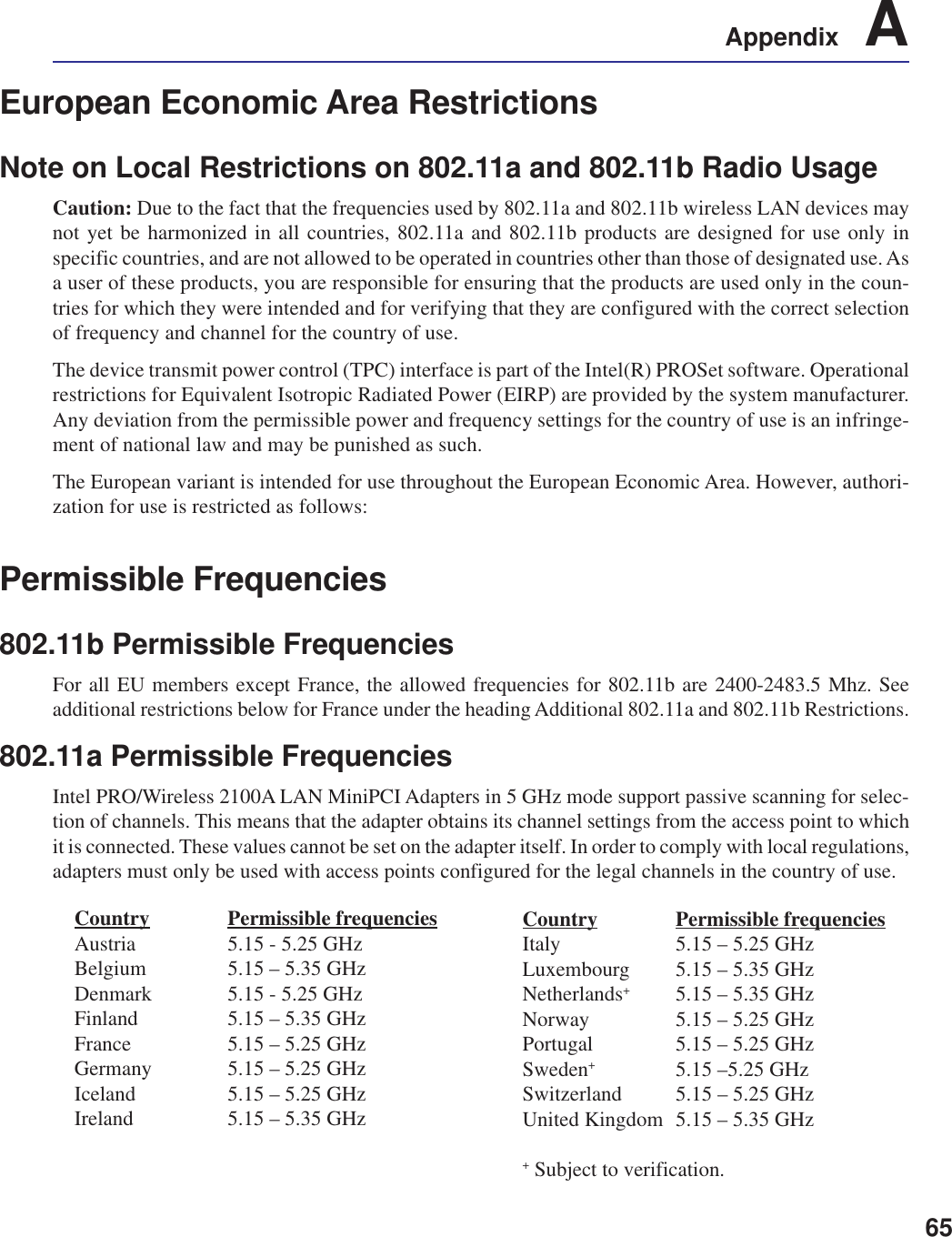
![63Appendix ADeclaration of Conformity (Dual-Band MiniPCI Adapter)[to be supplied]Product Descriptions:Intel® PRO/Wireless 2100A LAN 3B MiniPCI Adapter (model WM3B2100A)Intel Corporation declares that the equipment described in this document is in conformance with theessential requirements of the European Council Directives, standards, and other normative documentslisted below:• 73/23/EEC Safety of the User (article 3.1.a)• 89/336/EEC Electromagnetic Compatibility (article 3.1.b)• 1999/5/EC (R&TTE) Radio and Telecommunications Terminal Equipment Directive (Followingannex IV for model WM3B2100A)• EN 60950 1992 2nd Edition (A1 – A4, A11) Safety of Information Technology Equipment, Includ-ing Electrical Business Equipment• EN 300 328 V1.4.1 (April 2003) Electromagnetic compatibility and Radio spectrum Matters(ERM); Wideband Transmission system; data transmission equipment operating in the 2.4GHzISM band and using spread spectrum modulation techniques; Part 1: Technical characteristics andtest conditions; Part 2; Harmonized EN covering essential requirements under article 3.2 of theR&TTE Directive.• EN 301 489-1, Aug. 2000; EN 301489-17, Sept. 2000 – Electromagnetic compatibility and radiospectrum matters (ERM); electromagnetic compatibility (EMC) standard for radio equipment andservices: Part 1: Common technical requirements; Part 17: Specific conditions for Wideband Dataand HIPERLAN equipment.• Draft EN 301 893 v1.2.1, (2002-07) – Broadband Radio Access Networks (BRAN); 5 GHZ highperformance RLAN; Harmonized EN covering essential requirements of Article 3.2 of theR&TTE Directive.• IDA-TS-SSS, Following FCC OET bulletin 65 supplement C guidelines – Specific Absorption Rate(SAR) evaluating radio equipment for human exposure to radiofrequency electromagnetic fields.Warning: See 802.11a and 802.11b restrictions and guidelines for specific EU coun-tries, or regions within countries, under the heading “European Economic Area Re-strictions” below.](https://usermanual.wiki/ASUSTeK-Computer/M3000N.Revised-Manual-01122004/User-Guide-388223-Page-64.png)
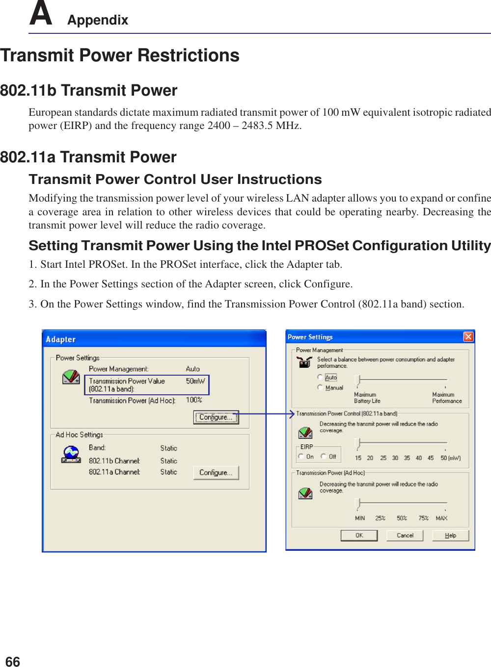
![64A AppendixTranslated Statements of Compliance[English]This product follows the provisions of the European Directive 1999/5/EC.[Danish]Dette produkt er i overensstemmelse med det europæiske direktiv 1999/5/EC[Dutch]Dit product is in navolging van de bepalingen van Europees Directief 1999/5/EC.[Finnish]Tämä tuote noudattaa EU-direktiivin 1999/5/EC määräyksiä.[French]Ce produit est conforme aux exigences de la Directive Européenne 1999/5/EC.[German]Dieses Produkt entspricht den Bestimmungen der Europäischen Richtlinie 1999/5/EC[Greek][Icelandic]essi vara stenst regluger Evrópska Efnahags Bandalagsins númer 1999/5/EC[Italian]Questo prodotto è conforme alla Direttiva Europea 1999/5/EC.[Norwegian]Dette produktet er i henhold til bestemmelsene i det europeiske direktivet 1999/5/EC.[Portuguese]Este produto cumpre com as normas da Diretiva Européia 1999/5/EC.[Spanish]Este producto cumple con las normas del Directivo Europeo 1999/5/EC.[Swedish]Denna produkt har tillverkats i enlighet med EG-direktiv 1999/5/EC.](https://usermanual.wiki/ASUSTeK-Computer/M3000N.Revised-Manual-01122004/User-Guide-388223-Page-65.png)