ASUSTeK Computer R2H Ultra Mobile PC User Manual Part 2
ASUSTeK Computer Inc Ultra Mobile PC Part 2
Contents
- 1. Part 1
- 2. Part 2
Part 2
UltraMobilePC
25
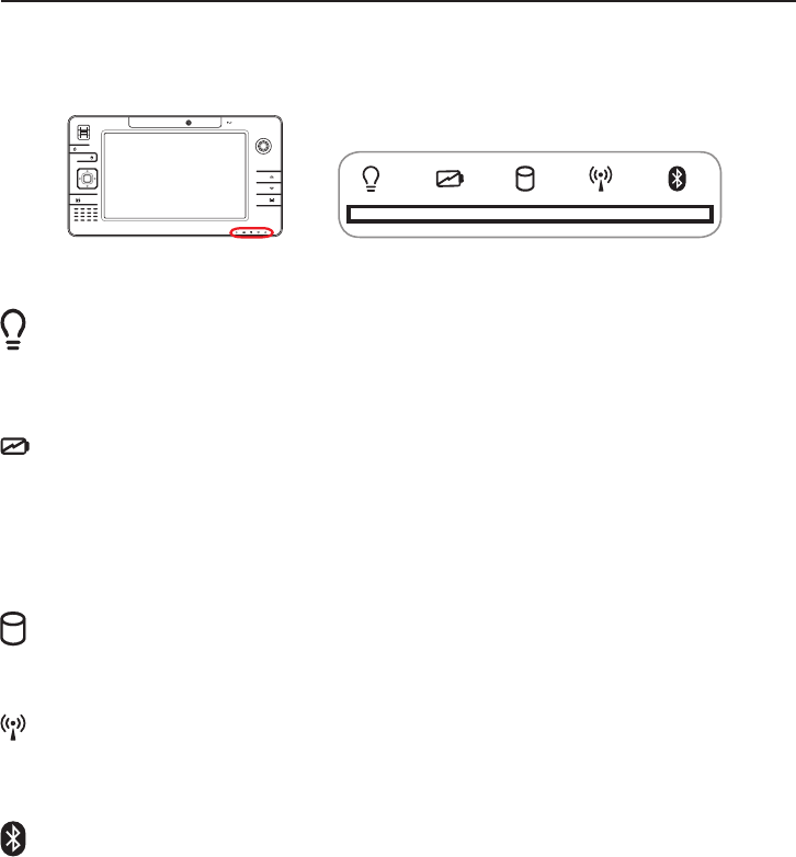
Status Indicators
Drive Activity Indicator
Indicates that the UltraMobilePC is accessing one or more storage device(s) such as the
hard disk. The light ashes proportional to the access time.
Bluetooth Indicator
This is only applicable on models with internal Bluetooth. This indicator will light to
show that the UltraMobilePC’s built-in Bluetooth function is activated.
Wireless LAN Indicator
When the built-in wireless LAN is enabled, this indicator will light. (Windows software
settings are necessary to use this function.)
Power Indicator
The power indicator lights when the UltraMobilePC is turned ON and blinks slowly
when the UltraMobilePC is in the Suspend-to-RAM (Standby) mode. This indicator is
OFF when the UltraMobilePC is turned OFF or in the Suspend-to-Disk (Hibernation)
Battery Charge Indicator
The battery charge indicator shows the status of the battery’s power as follows:
ON: The UltraMobilePC’s battery is charging when AC power is connected.
OFF: The UltraMobilePC’s battery is charged or completely drained.
Blinking: Battery power is less than 10% and the AC power is not connected.
1.3M
PIXELS

26
UltraMobilePC

UltraMobilePC
27
4. Using the UltraMobilePC
Operating System
Connections
Network Connection
Wireless LAN Connection
Bluetooth Wireless Connection
Power Management Modes
28
UltraMobilePC
Operating System
This UltraMobilePC may offer (depending on territory) its customers the choice of a pre-
installed operating system such as Microsoft Windows XP. The choices and languages will
depend on the territory. The levels of hardware and software support may vary depending
on the installed operating system. The stability and compatibility of other operating systems
cannot be guaranteed.
Support Software
This UltraMobilePC comes with a support CD that
provides BIOS, drivers and applications to enable hard-
ware features, extend functionality, help manage your
UltraMobilePC, or add functionality not provided by
the native operating system. If updates or replacement
of the support CD is necessary, contact your dealer for web sites to download individual
software drivers and utilities.
The support CD contains all drivers, utilities and software for all popular operating systems
including those that have been pre-installed. The support CD does not include the operating
system itself. The support CD is necessary even if your UltraMobilePC came pre-congured
in order to provide additional software not included as part of the factory pre-install.
A recovery CD is optional and includes an image of the original operating system installed
on the hard drive at the factory. The recovery CD provides a comprehensive recovery solu-
tion that quickly restores the UltraMobilePC’s operating system to its original working state
provided that your hard disk drive is in good working order. Contact your retailer if you
require such a solution.
Note: Some of the UltraMobilePC’s components and features may not
work until the device drivers and utilities are installed.
UltraMobilePC
29
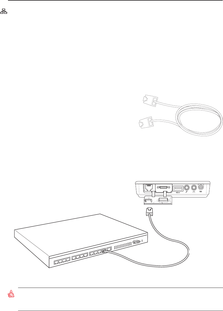
Example of the UltraMobilePC connected to a Network Hub or Switch for use with the
built-in Ethernet controller.
WARNING! Only use analog telephone outlets. The built-in modem does not support
the voltage used in digital phone systems. Do not connect the RJ-11 to digital phone
systems found in many commercial buildings or else damage will occur!
Network Hub or Switch
Network cable with RJ-45 connectors
Fast-Ethernet Connection
Connect a network cable, with RJ-45 connectors on each end, to the modem/network port
on the Notebook PC and the other end to a hub or switch. For 100 BASE-TX speeds, your
network cable must be category 5 or better (not category 3) with twisted-pair wiring. If you
plan on running the interface at 100Mbps, it must be connected to a 100 BASE-TX hub
(not a BASE-T4 hub). For 10Base-T, use category 3, 4, or 5 twisted-pair wiring. 10/100
Mbps Full-Duplex is supported on this Notebook PC but requires connection to a network
switching hub with “duplex” enabled. The software default is to use the fastest setting so no
user-intervention is required.
Twisted-Pair Cable
The cable used to connect the Ethernet card to a
host (generally a Hub or Switch) is called a straight-
through Twisted Pair Ethernet (TPE). The end
connectors are called RJ-45 connectors, which are
not compatible with RJ-11 telephone connectors. If
connecting two computers together without a hub in
between, a crossover LAN cable is required.
30
UltraMobilePC
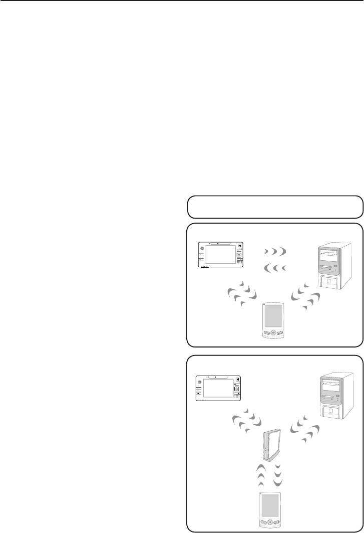
Infrastructure mode
The Infrastructure mode allows the UltraMo-
bilePC and other wireless devices to join a
wireless network created by an Access Point
(AP) (sold separately) that provides a central
link for wireless clients to communicate with
each other or with a wired network.
(All devices must install optional 802�11 wireless LAN
adapters�)
Ad-hoc mode
The Ad-hoc mode allows the UltraMobilePC
to connect to another wireless device. No
access point (AP) is required in this wireless
environment.
(All devices must install optional 802�11 wireless LAN
adapters�)
Wireless LAN Connection (on selected models)
The optional built-in wireless LAN is a compact easy-to-use wireless Ethernet adapter. Imple-
menting the IEEE 802.11 standard for wireless LAN (WLAN), the optional built-in wireless
LAN is capable of fast data transmission rates using Direct Sequence Spread Spectrum (DSSS)
and Orthogonal Frequency Division Multiplexing (OFDM) technologies on 2.4GHz/5GHz
frequencies. The optional built-in wireless LAN is backward compatible with the earlier
IEEE 802.11 standards allowing seamless interfacing of wireless LAN standards.
The optional built-in wireless LAN is a client adapter that supports Infrastructure and Ad-hoc
modes giving you exibility on your existing or future wireless network congurations for
distances up to 40 meters between the client and the access point.
To provide efcient security to your wireless communication, the optional built-in wireless
LAN comes with a 64-bit/128-bit Wired Equivalent Privacy (WEP) encryption and Wi-Fi
Protected Access (WPA) features.
These are examples of the UltraMobilePC
connected to a Wireless Network�
1.3M
PIXELS
Desktop PC
PDA
UltraMobilePC
Access
Point
Desktop PC
PDA
UltraMobilePC
1.3M
PIXELS
UltraMobilePC
31
1
2
3
4
5
6
7
*
#
8
0
9
g
p
t
j
a
d
m
?
w
+
a/A
ㄅ
ㄉㄚ
ㄓㄗ
ㄢㄦ
ㄕㄙ
ㄤㄨ
ㄖㄥ
ㄩ
ㄔㄘ
ㄣㄧ
ㄍㄐㄞ
ㄎㄑㄟ
ㄆ
ㄊㄛ
ㄏㄒ
ㄠㄡ
ㄇ
ㄜㄋ
ㄌ
ㄈㄝ
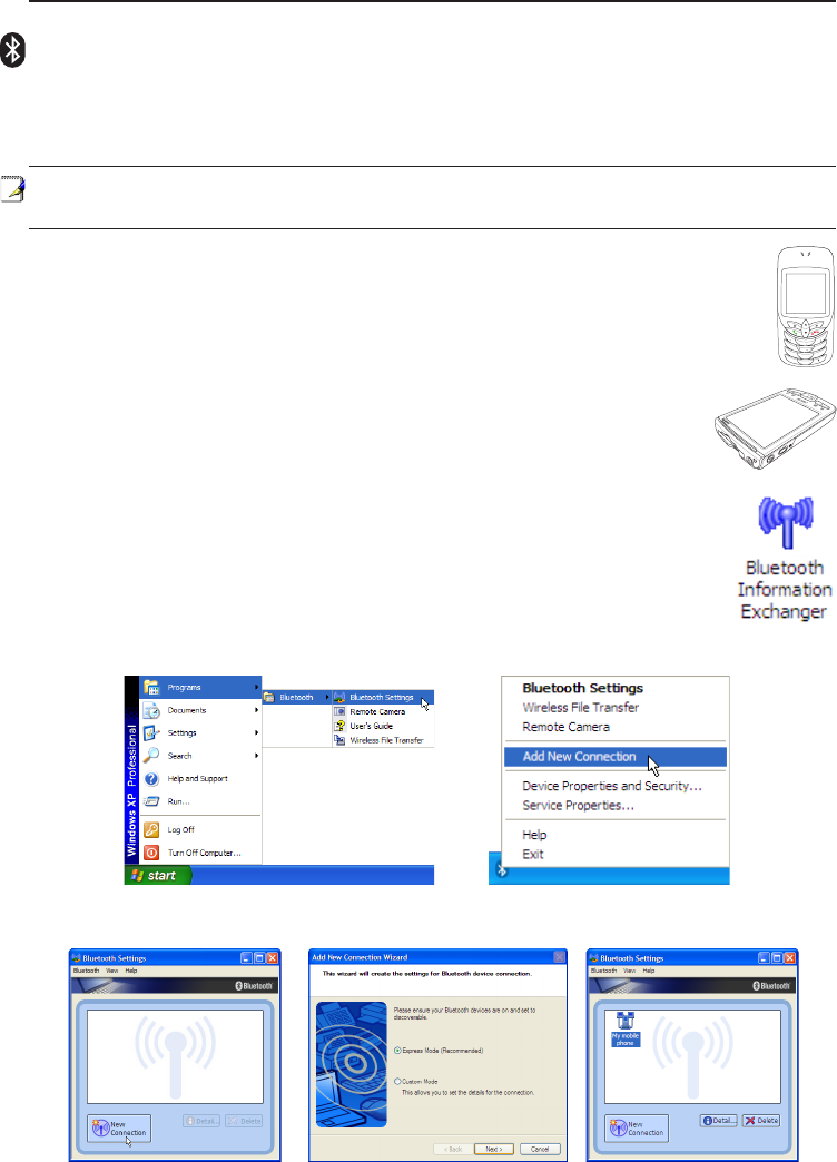
Bluetooth Wireless Connection (on selected models)
Notebook PCs with Bluetooth technology eliminates the need for cables for connecting
Bluetooth-enabled devices. Examples of Bluetooth-enabled devices may be Notebook PCs,
Desktop PCs, mobile phones, and PDAs.
Note: If your Notebook PC did not come with built-in Bluetooth, you need to connect a
USB Bluetooth module in order to use Bluetooth.
Bluetooth-enabled mobile phones
You can wireless connect to your mobile phone. Depending on your mobile phone’s
capabilities, you can transfer phone book data, photos, sound les, etc. or use it as
a modem to connect to the Internet. You may also use it for SMS messaging.
Bluetooth-enabled computers or PDAs
You can wireless connect to another computer or PDA and exchange les,
share peripherals, or share Internet or network connections. You may also
make use of Bluetooth-enabled wireless keyboard or mouse.
Pairing with Bluetooth-enabled devices
You rst need to pair your Notebook PC with a Bluetooth-enabled device before
you can connect to it. Make sure the Bluetooth-enabled device is turned ON
and ready to accept a pair. Launch Bluetooth Settings from Windows Start
| Programs | Bluetooth or select Add New Connection from the Bluetooth
taskbar icon if available.
Add New Connection from the
Bluetooth taskbar icon
Bluetooth Settings from Windows Start |
Programs | Bluetooth
Click New Connection from
Bluetooth Settings� Follow the wizard to add Bluetooth
devices� After complete, you should see
your device in the window�
32
UltraMobilePC
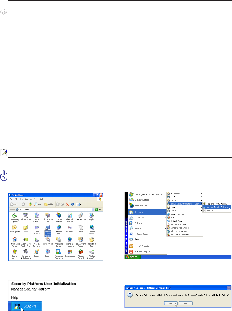
Trusted Platform Module (TPM) (on selected models)
The TPM, or Trusted Platform Module, is a security hardware device on the system board
that will hold computer-generated keys for encryption. It is a hardware-based solution that an
help avoid attacks by hackers looking to capture passwords and encryption keys to sensitive
data. The TPM provides the ability to the PC or notebook to run applications more secure
and to make transactions and communication more trustworthy.
The security features provided by the TPM are internally supported by the following cryp-
tographic capabilities of each TPM: hashing, random number generation, asymmetric key
generation, and asymmetric encryption/decryption. Each individual TPM on each individual
computer system has a unique signature initialized during the silicon manufacturing process
that further enhances its trust/security effectiveness. Each individual TPM must have an
Owner before it is useful as a security device.
TPM Applications
TPM is useful for any customer that is interested in providing an addition layer of security to
the computer system. The TPM, when bundled with an optional security software package, can
provide overall system security, le protection capabilities and protect against email/privacy
concerns. TPM helps provide security that can be stronger than that contained in the system
BIOS, operating system, or any non-TPM application.
Note: The TPM is disabled by default. Use BIOS setup to enable it.
Important: Use your TPM application’s “Restore” or “Migration” function to backup your
TPM security data.
TPM
You can launch the Security Platform
application from Windows “Control Panel”�
You can launch the Security Platform
application from Windows “Start” menu�
When the Security Platform is running, this
icon will show in the Windows taskbar� You
can choose to initialize or manage here�
When you launch the Security Platform
application for the rst time, answer Yes and
follow the instructions to congure it.

UltraMobilePC
33
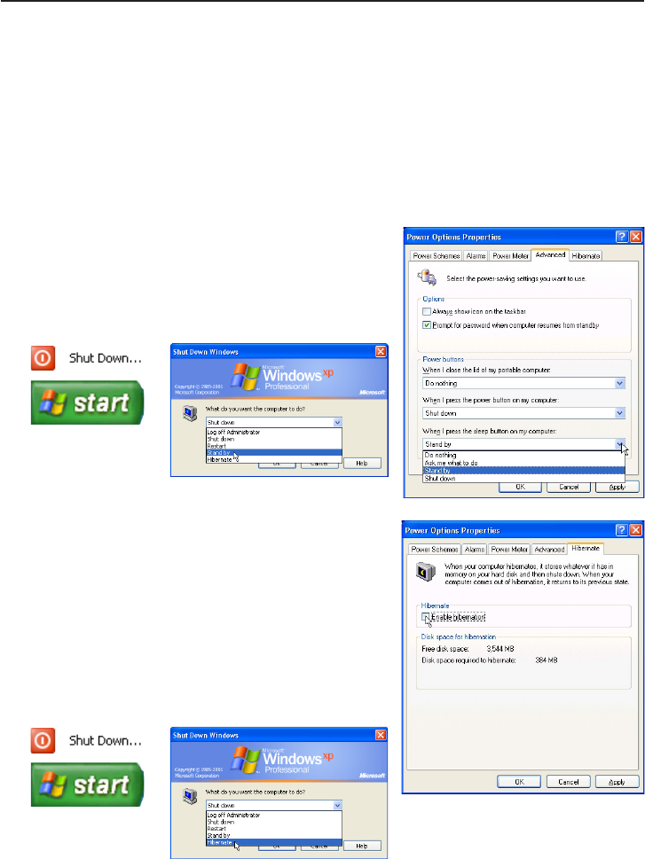
Power Management Modes
The UltraMobilePC has a number of automatic or adjustable power saving features that you can
use to maximize battery life and lower Total Cost of Ownership (TCO). You can control some
of these features through the Power menu in the BIOS Setup. ACPI power management settings
are made through the operating system. The power management features are designed to save
as much electricity as possible by putting components into a low power consumption mode as
often as possible but also allow full operation on demand. These low power modes are referred
to as “Stand by” (or Suspend-to-RAM) and “Hibernation” mode or Suspend-to-Disk (STD). The
Standby mode is a simple function provided by the operating system. When the UltraMobilePC
is in either one of the power saving modes, the status will be shown by the following: “Stand by”:
Power LED Blinks and “Hibernation”: Power LED OFF.
Full Power Mode & Maximum Performance
The UltraMobilePC operates in Full Power mode when the power management function is dis-
abled by conguring Windows power management and SpeedStep. When the UltraMobilePC is
operating in Full Power Mode, the Power LED remains ON. If you are conscious of both system
performance and power consumption, select “Maximum Performance” instead of disabling all
power management features.
ACPI
Advanced Conguration and Power Management (ACPI) was developed by Intel, Microsoft, and
Toshiba especially for Windows and later to control power management and Plug and Play features.
ACPI is the new standard in power management for UltraMobilePCs.
Suspend Mode
In “Stand by” (STR) and “Hibernation” (STD), the CPU clock is stopped and most of the Ultra-
MobilePC devices are put in their lowest active state. The suspend mode is the lowest power state
of the UltraMobilePC. The UltraMobilePC enters suspend mode when the system remains idle
for a specied amount of time or manually using the [Fn][F1] keys. The Power LED blinks when
the UltraMobilePC is in STR mode. In STD mode, the UltraMobilePC will appear to be powered
OFF. Recover from STR by pressing any keyboard button (except Fn). Recover from STD
by using the power switch (just like powering ON the UltraMobilePC).
Power Savings
In addition to reducing the CPU clock, this mode puts devices including the LCD backlight in their
lower active state. The UltraMobilePC enters “Stand by” mode (low priority) when the system
remains idle for a specied amount of time. The time-out can be set through Windows power
management (higher priority). To resume system operation, press any key.
NOTE: APM was used in older operating systems like Windows NT4 and Windows 98.
Because newer operating systems like Windows XP, Windows 2000, and Windows
ME utilize ACPI, APM is no longer fully supported on this UltraMobilePC.

34
UltraMobilePC
Thermal Power Control
There are three power control methods for controlling the UltraMobilePC’s thermal state.
These power control cannot be congured by the user and should be known in case the
UltraMobilePC should enter these states. The following temperatures represent the chassis
temperature (not CPU).
• The fan turns ON for active cooling when the temperature reaches the safe upper limit.
• The CPU decreases speed for passive cooling when the temperature exceeds the safe
upper limit.
• The system shut down for critical cooling when temperature exceeds the maximum safe
upper limit.
Power State Summary
STATE ENTRY EVENT EXIT EVENT
“Stand by”
• “Stand by” through Windows Start button
• Timer as set though “Power Management”
in Windows Control Panel (higher priority)
• Any device
• Battery low
STR (“Stand by”)
(Suspend-to-RAM)
• Hotkey (see “Colored Hotkeys” under
“Special Keyboard Functions” in the
previous section)
• Signal from modem port
• Power button or any key
STD (“Hibernate”)
(Suspend-to-Disk)
• Hotkey (see “Colored Hotkeys” under
“Special Keyboard Functions” in the
previous section)
• Power button
Soft OFF • Power button (can be set as STR or STD)
• “Shut down” through Windows Start button
• Power button
UltraMobilePC
35
Stand by and Hibernate
Power management settings can be found in the Windows control panel. The following shows
the power options properties in Windows. You can dene “Stand By” or “Shut down” for
closing the display panel, pressing the power button, or activating sleep mode. “Stand by”
and “Hibernate” saves power when your UltraMobilePC is not in use by turning OFF certain
components. When you resume your work, your last status (such as a document scrolled
down half way or email typed half way) will reappear as if you never left. “Shut down” will
close all applications and ask if you want to save your work if any are not saved.
“Stand by” is the same as Suspend-to-RAM (STR).
This function stores your current data and status in RAM
while many components are turned OFF. Because RAM
is volatile, it requires power to keep (refresh) the data. To
operate: select “Start” | “Shut down”, and “Stand by”.
“Hibernate” is the same as Suspend-to-Disk (STD) and
stores your current data and status on the hard disk drive.
By doing this, RAM does not have to be periodically
refreshed and power consumption is greatly reduced
but not completely eliminated because certain wake-
up components like LAN needs to remain powered.
“Hibernate” saves more power compared to “Stand by”.
To operate: Enable hibernation in “Power Options” and
select “Start” | “Shut down”, and “Hibernate”.

36
UltraMobilePC

UltraMobilePC
37
Appendix
Optional Accessories
Optional Connections
Glossary
Declarations and Safety Statements
UltraMobilePC Information
38
UltraMobilePC
PgUp
PgDn
PrtSc
Break
Pause
SysRq
F1 F2 F3 F4 F5 F6 F7F7 F8F8 F9F9
F 10F 10
F11F1
F 1F 12
Home
End
LOCK UNLOCK
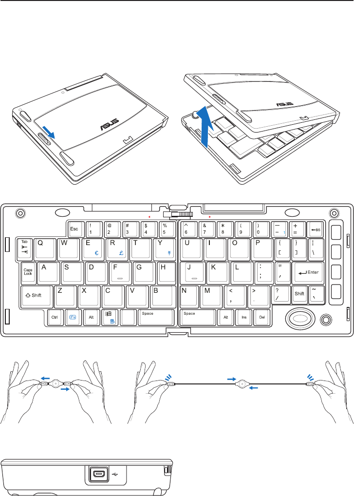
Optional Accessories
These items, if desired, come as optional items to complement your UltraMobilePC.
Foldable USB Keyboard
Slide latch
on the side
to open�
Slide latch on the top to lock the keyboard in the open position�
Pull the USB connectors apart
(not fully) to extend the mini-USB
cable�
Pull the USB connectors fully apart and slowly retract the mini-USB
cable�
Connect the mini USB cable to the foldable USB
keyboard and to this mini-USB port�
UltraMobilePC
39
1 2 3 4
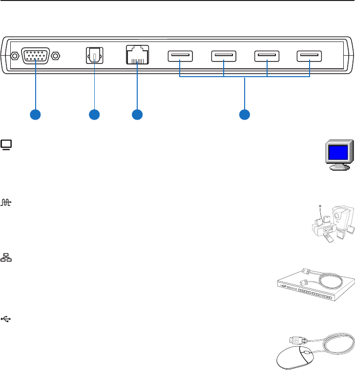
PortBar
LAN Port
The RJ-45 LAN port with eight pins is larger than the RJ-11 mo-
dem port and supports a standard Ethernet cable for connection
to a local network. The built-in connector allows convenient use
without additional adapters.
Display (Monitor) Output
The 15-pin D-sub output is an analog port that supports a standard VGA-
compatible device such as a monitor or projector to allow viewing on a larger
external display.
SPDIF Output Jack (SPDIF Output)
This jack provides connection to SPDIF (Sony/Philips Digital Interface)
compliant devices for digital audio output. Use this feature to turn the
Notebook PC into a hi- home entertainment system.
2.0
USB Port (2.0/1.1)
The USB (Universal Serial Bus) port is compatible with USB 2.0
or USB 1.1 devices such as keyboards, pointing devices, cameras,
hard disk drives, printers, and scanners connected in a series up to
12Mbits/sec (USB 1.1) and 480Mbits/sec (USB 2.0). USB allows
many devices to run simultaneously on a single computer, with some peripherals acting
as additional plug-in sites or hubs. USB supports hot-swapping of devices so that most
peripherals can be connected or disconnected without restarting the computer.
40
UltraMobilePC
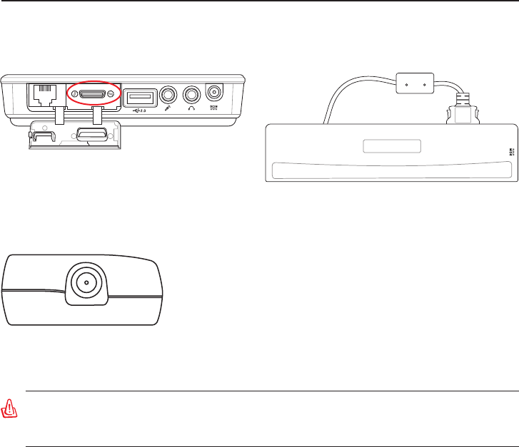
PortBar (Cont.)
Plug the PortBar to the expansion port� Keep the PortBar connector in the keeper when not
in use to protect the contacts�
Plug the Notebook PC’s power adapter into this power
port so that you can easily free the UltraMobilePC
from all your peripherals with just one connector�
WARNING! You must plug the power adapter into the UltraMobilePC or PortBar
when you use PortBar. The PortBar must not be used when the UltraMobilePC is
operating in battery mode.
UltraMobilePC
41
More Optional Accessories
These items, if desired, come as optional items to complement your UltraMobilePC.
USB Flash Memory Disk
A USB ash memory disk is an optional item that can
replace the 1.44MB oppy disk and provide storage up
to several hundred megabytes, higher transfer speeds,
and greater durability. When used in current operating
systems, no drivers are necessary.
USB Keyboard and Mouse
Attaching an external USB keyboard will allow data entry to
be more comfortable. Attaching an external USB mouse will
allow Windows navigation to be more comfortable. Both the
external USB keyboard and mouse will work simultaneously
with the UltraMobilePC’s built-in keyboard and touchpad.
USB Floppy Disk Drive
An optional USB-interface oppy disk drive can accept a
standard 1.44MB (or 720KB) 3.5-inch oppy diskette.
WARNING! To prevent system failures, use (Safely
Remove Hardware) on the taskbar before disconnect-
ing the USB oppy disk drive. Eject the oppy disk
before transporting the UltraMobilePC to prevent
damage from shock.
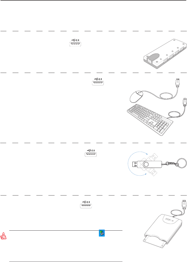
USB Hub (Optional)
Attaching an optional USB hub will increase your USB ports
and allow you to quickly connect or disconnect many USB
peripherals through a single cable.
42
UltraMobilePC
Optional Connections
These items, if desired, may be purchased from third-parties.
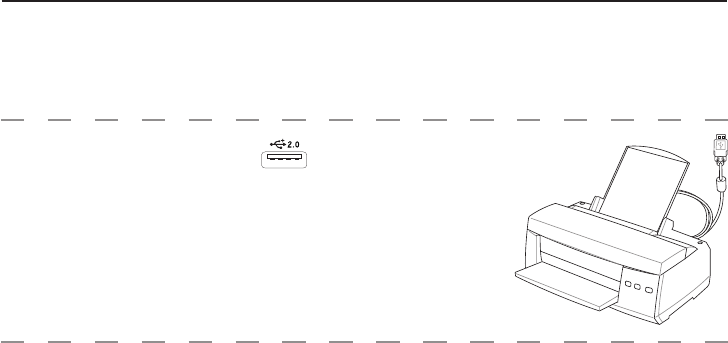
Printer Connection
One or more USB printers can be simultaneously used on
any USB port or USB hub.

UltraMobilePC
43
Federal Communications Commission Statement
This device complies with FCC Rules Part 15. Operation is subject to the following two
conditions:
• This device may not cause harmful interference, and
• This device must accept any interference received, including interference that may cause
undesired operation.
This equipment has been tested and found to comply with the limits for a class B digital device,
pursuant to Part 15 of the Federal Communications Commission (FCC) rules. These limits
are designed to provide reasonable protection against harmful interference in a residential
installation. This equipment generates, uses, and can radiate radio frequency energy and, if not
installed and used in accordance with the instructions, may cause harmful interference to radio
communications. However, there is no guarantee that interference will not occur in a particular
installation. If this equipment does cause harmful interference to radio or television reception,
which can be determined by turning the equipment off and on, the user is encouraged to try to
correct the interference by one or more of the following measures:
• Reorient or relocate the receiving antenna.
• Increase the separation between the equipment and receiver.
• Connect the equipment into an outlet on a circuit different from that to which the receiver
is connected.
• Consult the dealer or an experienced radio/TV technician for help.
(Reprinted from the Code of Federal Regulations #47, part 15.193, 1993. Washington DC: Of-
ce of the Federal Register, National Archives and Records Administration, U.S. Government
Printing Ofce.)
WARNING! The use of a shielded-type power cord is required in order to meet FCC
emission limits and to prevent interference to the nearby radio and television recep-
tion. It is essential that only the supplied power cord be used. Use only shielded
cables to connect I/O devices to this equipment. You are cautioned that changes
or modications not expressly approved by the party responsible for compliance
could void your authority to operate the equipment.
44
UltraMobilePC
This equipment complies with FCC radiation exposure limits set forth for an uncontrolled
environment. To maintain compliance with FCC RF exposure compliance requirements,
please avoid direct contact to the transmitting antenna during transmitting. End users must
follow the specic operating instructions for satisfying RF exposure compliance.
Declaration of Conformity (R&TTE directive 1999/5/EC)
The following items were completed and are considered relevant and sufcient:
• Essential requirements as in [Article 3]
• Protection requirements for health and safety as in [Article 3.1a]
• Testing for electric safety according to [EN 60950]
• Protection requirements for electromagnetic compatibility in [Article 3.1b]
• Testing for electromagnetic compatibility in [EN 301 489-1] & [EN 301 489-17]
•
•
Effective use of the radio spectrum as in [Article 3.2]
Radio test suites according to [EN 300 328]
FCC Caution: Any changes or modications not expressly approved by the party
responsible for compliance could void the user’s authority to operate this equipment.
“The manufacture declares that this device is limited to Channels 1 through 11 in the
2.4GHz frequency by specied rmware controlled in the USA.”
FCC Radio Frequency (RF) Exposure Caution Statement
IMPORTANT: This device and its antenna(s) must not be co-located or operating in
conjunction with any other antenna or transmitter.

UltraMobilePC
45
CE Mark Warning
This is a Class B product, in a domestic environment, this product may cause radio interference,
in which case the user may be required to take adequate measures.
IC Radiation Exposure Statement for Canada
This equipment complies with IC radiation exposure limits set forth for an uncontrolled
environment. To maintain compliance with IC RF exposure compliance requirements, please
avoid direct contact to the transmitting antenna during transmitting. End users must follow
the specic operating instructions for satisfying RF exposure compliance.
Operation is subject to the following two conditions:
• This device may not cause interference and
• This device must accept any interference, including interference that may cause undesired
operation of the device.
To prevent radio interference to the licensed service (i.e. co-channel Mobile Satellite
systems) this device is intended to be operated indoors and away from windows to provide
maximum shielding. Equipment (or its transmit antenna) that is installed outdoors is subject
to licensing.

46
UltraMobilePC
France Restricted Wireless Frequency Bands
Some areas of France have a restricted frequency band. The worst case maximum authorized
power indoors are:
• 10mW for the entire 2.4 GHz band (2400 MHz–2483.5 MHz)
• 100mW for frequencies between 2446.5 MHz and 2483.5 MHz
Wireless Operation Channel for Different Domains
N. America 2.412-2.462 GHz Ch01 through CH11
Japan 2.412-2.484 GHz Ch01 through Ch14
Europe ETSI 2.412-2.472 GHz Ch01 through Ch13
NOTE: Your WLAN Card transmits less than 100mW, but more than 10mW.
There are few possibilities for outdoor use: On private property or on the private property
of public persons, use is subject to a preliminary authorization procedure by the Ministry
of Defense, with maximum authorized power of 100mW in the 2446.5–2483.5 MHz band.
Use outdoors on public property is not permitted.
In the departments listed below, for the entire 2.4 GHz band:
• Maximum authorized power indoors is 100mW
• Maximum authorized power outdoors is 10mW
Departments in which the use of the 2400–2483.5 MHz band is permitted with an EIRP of
less than 100mW indoors and less than 10mW outdoors:
01 Ain Orientales 02 Aisne 03 Allier 05 Hautes Alpes
08 Ardennes 09 Ariège 11 Aude 12 Aveyron
16 Charente 24 Dordogne 25 Doubs 26 Drôme
32 Gers 36 Indre 37 Indre et Loire 41 Loir et Cher
45 Loiret 50 Manche 55 Meuse 58 Nièvre
59 Nord 60 Oise 61 Orne 63 Puy du Dôme
64 Pyrénées Atlantique 66 Pyrénées 67 Bas Rhin 68 Haut Rhin
70 Haute Saône 71 Saône et Loire 75 Paris 82 Tarn et Garonne
84 Vaucluse 88 Vosges 89 Yonne 90 Territoire de Belfort
94 Val de Marne
This requirement is likely to change over time, allowing you to use your wireless LAN
card in more areas within France. Please check with ART for the latest information (www.
art-telecom.fr)
NOTE: Channels 10 through 13 inclusive operate in the band 2446.6 MHz to 2483.5
MHz.

UltraMobilePC
47
UL Safety Notices
Required for UL 1459 covering telecommunications (telephone) equipment intended to
be electrically connected to a telecommunication network that has an operating voltage to
ground that does not exceed 200V peak, 300V peak-to-peak, and 105V rms, and installed
or used in accordance with the National Electrical Code (NFPA 70).
When using the UltraMobilePC modem, basic safety precautions should always be followed
to reduce the risk of re, electric shock, and injury to persons, including the following:
• Do not use the UltraMobilePC near water, for example, near a bath tub, wash bowl,
kitchen sink or laundry tub, in a wet basement or near a swimming pool.
• Do not use the UltraMobilePC during an electrical storm. There may be a remote risk
of electric shock from lightning.
• Do not use the UltraMobilePC in the vicinity of a gas leak.
Required for UL 1642 covering primary (non-rechargeable) and secondary (rechargeable)
lithium batteries for use as power sources in products. These batteries contain metallic
lithium, or a lithium alloy, or a lithium ion, and may consist of a single electrochemical cell
or two or more cells connected in series, parallel, or both, that convert chemical energy into
electrical energy by an irreversible or reversible chemical reaction.
• Do not dispose the UltraMobilePC battery pack in a re, as they may explode. Check
with local codes for possible special disposal instructions to reduce the risk of injury to
persons due to re or explosion.
• Do not use power adapters or batteries from other devices to reduce the risk of injury
to persons due to re or explosion. Use only UL certied power adapters or batteries
supplied by the manufacturer or authorized retailers.
Power Safety Requirement
Products with electrical current ratings up to 6A and weighing more than 3Kg must use
approved power cords greater than or equal to: H05VV-F, 3G, 0.75mm2 or H05VV-F, 2G,
0.75mm2.

48
UltraMobilePC
Nordic Lithium Cautions (for lithium-ion batteries)
CAUTION! Danger of explosion if battery is incorrectly replaced. Replace only with the
same or equivalent type recommended by the manufacturer. Dispose of used batteries ac-
cording to the manufacturer’s instructions. (English)
ATTENZIONE! Rischio di esplosione della batteria se sostituita in modo errato. Sostituire
la batteria con un una di tipo uguale o equivalente consigliata dalla fabbrica. Non disperdere
le batterie nell’ambiente. (Italian)
VORSICHT! Explosionsgetahr bei unsachgemäßen Austausch der Batterie. Ersatz nur durch
denselben oder einem vom Hersteller empfohlenem ähnlichen Typ. Entsorgung gebrauchter
Batterien nach Angaben des Herstellers. (German)
ADVARSELI! Lithiumbatteri - Eksplosionsfare ved fejlagtig håndtering. Udskiftning må kun
ske med batteri af samme fabrikat og type. Levér det brugte batteri tilbage til leverandøren.
(Danish)
VARNING! Explosionsfara vid felaktigt batteribyte. Använd samma batterityp eller en ekviva-
lent typ som rekommenderas av apparattillverkaren. Kassera använt batteri enligt fabrikantens
instruktion. (Swedish)
VAROITUS! Paristo voi räjähtää, jos se on virheellisesti asennettu. Vaihda paristo ainoastaan
laitevalmistajan sousittelemaan tyyppiin. Hävitä käytetty paristo valmistagan ohjeiden mukaisesti.
(Finnish)
ATTENTION! Il y a danger d’explosion s’il y a remplacement incorrect de la batterie.
Remplacer uniquement avec une batterie du mêre type ou d’un type équivalent recommandé
par le constructeur. Mettre au rebut les batteries usagées conformément aux instructions du
fabricant. (French)
ADVARSEL! Eksplosjonsfare ved feilaktig skifte av batteri. Benytt samme batteritype eller
en tilsvarende type anbefalt av apparatfabrikanten. Brukte batterier kasseres i henhold til
fabrikantens instruksjoner. (Norwegian)
(Japanese)