ASUSTeK Computer RTACHC00 Wireless-AC1750 Dual Band Gigabit Router,Wireless-AC1900 Dual Band Gigabit Router User Manual Part 1
ASUSTeK Computer Inc Wireless-AC1750 Dual Band Gigabit Router,Wireless-AC1900 Dual Band Gigabit Router Users Manual Part 1
Contents
- 1. Users Manual Part 1
- 2. Users Manual Part 2
- 3. User Manual - Part 1
- 4. User Manual - Part 2
Users Manual Part 1
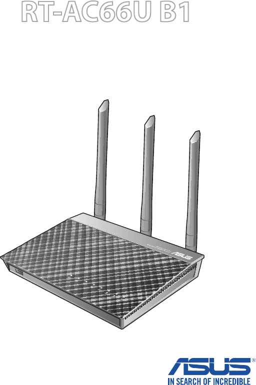
RT-AC66U B1
Wireless-AC1750 Dual Band Gigabit
Router
User Guide

2
Copyright © 2016 ASUSTeK Computer Inc. All Rights Reserved.
No part of this manual, including the products and software described
in it, may be reproduced, transmitted, transcribed, stored in a retrieval
system, or translated into any language in any form or by any means, except
documentation kept by the purchaser for backup purposes, without the
express written permission of ASUSTeK Computer Inc. (“ASUS”).
Product warranty or service will not be extended if: (1) the product is repaired,
modied or altered, unless such repair, modication of alteration is authorized
in writing by ASUS; or (2) the serial number of the product is defaced or
missing.
ASUS PROVIDES THIS MANUAL “AS IS” WITHOUT WARRANTY OF ANY KIND,
EITHER EXPRESS OR IMPLIED, INCLUDING BUT NOT LIMITED TO THE IMPLIED
WARRANTIES OR CONDITIONS OF MERCHANTABILITY OR FITNESS FOR A
PARTICULAR PURPOSE. IN NO EVENT SHALL ASUS, ITS DIRECTORS, OFFICERS,
EMPLOYEES OR AGENTS BE LIABLE FOR ANY INDIRECT, SPECIAL, INCIDENTAL,
OR CONSEQUENTIAL DAMAGES (INCLUDING DAMAGES FOR LOSS OF PROFITS,
LOSS OF BUSINESS, LOSS OF USE OR DATA, INTERRUPTION OF BUSINESS
AND THE LIKE), EVEN IF ASUS HAS BEEN ADVISED OF THE POSSIBILITY OF
SUCH DAMAGES ARISING FROM ANY DEFECT OR ERROR IN THIS MANUAL OR
PRODUCT.
SPECIFICATIONS AND INFORMATION CONTAINED IN THIS MANUAL ARE
FURNISHED FOR INFORMATIONAL USE ONLY, AND ARE SUBJECT TO CHANGE
AT ANY TIME WITHOUT NOTICE, AND SHOULD NOT BE CONSTRUED AS A
COMMITMENT BY ASUS. ASUS ASSUMES NO RESPONSIBILITY OR LIABILITY
FOR ANY ERRORS OR INACCURACIES THAT MAY APPEAR IN THIS MANUAL,
INCLUDING THE PRODUCTS AND SOFTWARE DESCRIBED IN IT.
Products and corporate names appearing in this manual may or may not be
registered trademarks or copyrights of their respective companies, and are used
only for identication or explanation and to the owners’ benet, without intent
to infringe.
E11885
Revised Edition v2
July 2016

3
Table of contents
1 Getting to know your wireless router 6
1.1 Welcome! ........................................................................................6
1.2 Package contents ......................................................................... 6
1.3 Your wireless router .....................................................................7
1.4 Positioning your router .............................................................. 9
1.5 Setup Requirements ................................................................ 10
1.6 Router Setup ............................................................................... 11
1.6.1 Wired connection ..................................................................11
1.6.2 Wireless connection ............................................................. 12
2 Getting started 14
2.1 Logging into the Web GUI ..................................................... 14
2.2 Quick Internet Setup (QIS) with Auto-detection ........... 15
2.3 Connecting to your wireless network ................................ 19
3 Conguring the General settings 20
3.1 Using the Network Map ......................................................... 20
3.1.1 Setting up the wireless security settings ......................21
3.1.2 Managing your network clients ....................................... 22
3.1.3 Monitoring your USB device .............................................23
3.2 Creating a Guest Network ...................................................... 26
3.3 Using the Trac Manager ...................................................... 28
3.3.1 Managing QoS (Quality of Service) Bandwidth..........28
3.3.2 Monitoring Trac .................................................................31
3.4 Setting up Parental Control ................................................... 32
3.5 Using the USB Application ..................................................... 33
3.5.1 Using AiDisk ............................................................................... 33
3.5.2 Using Servers Center ............................................................35
3.5.3 3G/4G ........................................................................................40

4
Table of contents
3.6 Using AiCloud 2.0 ...................................................................... 41
3.6.1 Cloud Disk ................................................................................42
3.6.2 Smart Access ...........................................................................44
3.6.3 Smart Sync ............................................................................... 45
4 Conguring the Advanced Settings 46
4.1 Wireless ......................................................................................... 46
4.1.1 General ......................................................................................46
4.1.2 WPS ............................................................................................49
4.1.3 Wireless MAC Filter ...............................................................51
4.1.4 RADIUS Setting ......................................................................52
4.1.5 Professional .............................................................................53
4.2 LAN ................................................................................................. 55
4.2.1 LAN IP ........................................................................................55
4.2.2 DHCP Server ............................................................................56
4.2.3 Route .........................................................................................58
4.2.4 IPTV ............................................................................................... 59
4.3 WAN ............................................................................................... 60
4.3.1 Internet Connection .............................................................60
4.3.2 Port Trigger ..............................................................................63
4.3.3 Virtual Server/Port Forwarding ........................................65
4.3.4 DMZ............................................................................................68
4.3.5 DDNS .........................................................................................69
4.3.6 NAT Passthrough ................................................................... 70
4.4 IPv6 ................................................................................................. 71
4.5 VPN Server ................................................................................... 72
4.6 Firewall .......................................................................................... 73
4.6.1 General ......................................................................................73
4.6.2 URL Filter ..................................................................................73
4.6.3 Keyword lter .........................................................................74
4.6.4 Network Services Filter .......................................................75

5
Table of contents
4.7 Administration ........................................................................... 77
4.7.1 Operation Mode ....................................................................77
4.7.2 System ....................................................................................... 78
4.7.3 Firmware Upgrade ................................................................79
4.7.4 Restore/Save/Upload Setting ...........................................79
4.8 System Log .................................................................................. 80
5 Utilities 81
5.1 Device Discovery ....................................................................... 81
5.2 Firmware Restoration .............................................................. 82
5.3 Setting up your printer server .............................................. 83
5.3.1 ASUS EZ Printer Sharing .....................................................83
5.3.2 Using LPR to Share Printer .................................................87
5.4 Download Master ...................................................................... 92
5.4.1 Conguring Bit Torrent download settings .................93
5.4.2 NZB settings ............................................................................ 94
6 Troubleshooting 95
6.1 Basic Troubleshooting ............................................................. 95
6.2 Frequently Asked Questions (FAQs) .................................. 98
Appendices 107
Notices .....................................................................................................107
ASUS Contact information ..................................................................124
Networks Global Hotline Information.............................................125
6
1 Getting to know your wireless
router
NOTES:
• Ifanyoftheitemsaredamagedormissing,contactASUSfor
technical inquiries and support, Refer to the ASUS Support Hotline
list at the back of this user manual.
• Keeptheoriginalpackagingmaterialincaseyouwouldneedfuture
warranty services such as repair or replacement.
RT-AC66U B1 Wireless Router Network cable (RJ-45)
Power adapter Quick Start Guide
Support CD (Manual, utility software) Warranty card
1.1 Welcome!
Thank you for purchasing an ASUS RT-AC66U B1 Wireless Router!
The ultra-thin and stylish RT-AC66U B1 features a 2.4GHz and
5GHz dual bands for an unmatched concurrent wireless HD
streaming; SMB server, UPnP AV server, and FTP server for 24/7
le sharing; a capability to handle 300,000 sessions; and the ASUS
Green Network Technology, which provides up to 70% power-
saving solution.
1.2 Package contents
7
1.3 Your wireless router
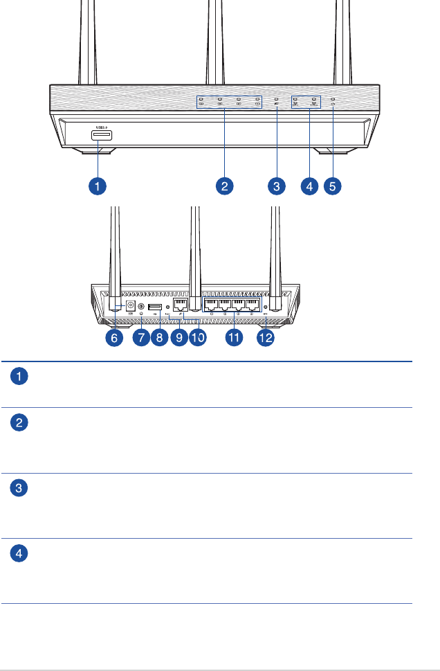
USB 3.0 port
Insert a USB 3.0 device such as USB hard disks or USB ash drives into this
port.
LAN LED
O: No power or no physical connection.
On: Has physical connection to a local area network (LAN).
Flashing: Transmitting or receiving data via wireless connection.
WAN LED
O: No power or no physical connection.
On: Has physical connection to a wide area network (WAN).
Flashing: Transmitting or receiving data via wireless connection.
2.4GHz LED / 5GHz LED
O: No 2.4GHz or 5GHz signal.
On: Wireless system is ready.
Flashing: Transmitting or receiving data via wireless connection.

8
NOTES:
• Useonlytheadapterthatcamewithyourpackage.Usingother
adapters may damage the device.
• Specications:
DC Power adapter DC Output: +19V with max 1.75A current;
Operating
Temperature 0~40oC Storage 0~70oC
Operating Humidity 50~90% Storage 20~90%
Power LED
O: No power.
On: Device is ready.
Flashing slow: Rescue mode
Flashing quick: WPS is processing.
Power (DC-IN) port
Insert the bundled AC adapter into this port and connect your router to a
power source.
Power button
Press this button to power on or o the system.
USB 2.0 port
Insert a USB 2.0 device such as a USB hard disk or USB ash drive into this port.
Insert your iPad’s USB cable into one of these ports to charge your iPad.
Reset button
This button resets or restores the system to its factory default settings.
WAN (Internet) port
Connect a network cable into this port to establish WAN connection.
LAN 1 ~ 4 ports
Connect network cables into these ports to establish LAN connection.
WPS button
This button launches the WPS Wizard.
9
1.4 Positioning your router
For the best wireless signal transmission between the wireless
router and the network devices connected to it, ensure that you:
• Placethewirelessrouterinacentralizedareaforamaximum
wireless coverage for the network devices.
• Keepthedeviceawayfrommetalobstructionsandawayfrom
direct sunlight.
• Topreventsignalinterferenceorloss,keepthedeviceaway
from 802.11g or 20MHz only Wi-Fi devices, 2.4GHz computer
peripherals, Bluetooth devices, cordless phones, transformers,
heavy-duty motors, uorescent lights, microwave ovens,
refrigerators, and other industrial equipment.
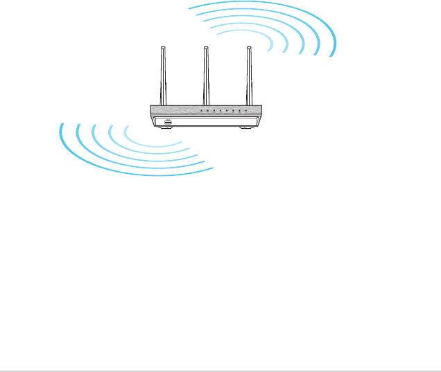
• Toensurethebestwirelesssignal,orientthethreedetachable
antennas as shown in the drawing below.
90°
90°

10
1.5 Setup Requirements
To set up your wireless network, you need a computer that meets
the following system requirements:
• EthernetRJ-45(LAN)port(10Base-T/100Base-TX/
1000BaseTX)
• IEEE802.11a/b/g/n/acwirelesscapability
• AninstalledTCP/IPservice
• WebbrowsersuchasInternetExplorer,Firefox,Safari,or
Google Chrome
NOTES:
• Ifyourcomputerdoesnothavebuilt-inwirelesscapabilities,youmay
install an IEEE 802.11a/b/g/n/ac WLAN adapter to your computer to
connect to the network.
• Withitsdualbandtechnology,yourwirelessroutersupports2.4GHz
and 5GHz wireless signals simultaneously. This allows you to do
Internet-related activities such as Internet surng or reading/writing
e-mail messages using the 2.4GHz band while simultaneously
streaming high-denition audio/video les such as movies or music
using the 5GHz band.
• SomeIEEE802.11ndevicesthatyouwanttoconnecttoyournetwork
may or may not support 5GHz band. Refer to the device's manual for
specications.
• TheEthernetRJ-45cablesthatwillbeusedtoconnectthenetwork
devices should not exceed 100 meters.
11
1.6 Router Setup
IMPORTANT!
• Useawiredconnectionwhensettingupyourwirelessrouterto
avoid possible setup problems.
• BeforesettingupyourASUSwirelessrouter,dothefollowing:
• Ifyouarereplacinganexistingrouter,disconnectitfromyour
network.
• Disconnectthecables/wiresfromyourexistingmodemsetup.If
your modem has a backup battery, remove it as well.
• Rebootyourcablemodemandcomputer(recommended).
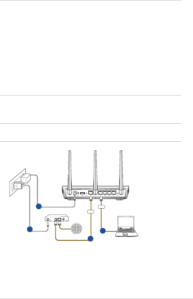
1.6.1 Wired connection
NOTE: You can use either a straight-through cable or a crossover cable
for wired connection.
To set up your wireless router via wired connection:
1. Insert your wireless router’s AC adapter to the DC-IN port and
plug it to a power outlet.
RT-AC66U B1
3
WAN
1
42
LAN
Internet
Modem
12
2. Using the bundled network cable, connect your computer to
your wireless router’s LAN port.
IMPORTANT! Ensure that the LAN LED is blinking.
3 Using another network cable, connect your modem to your
wireless router’s WAN port.
4. Insert your modem’s AC adapter to the DC-IN port and plug it
to a power outlet.
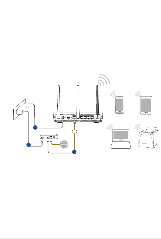
1.6.2 Wireless connection
PrinterLaptop
TabletSmart phone
RT-AC66U B1
2
WAN
1
3
Internet
Modem
To set up your wireless router via wireless connection:
1. Insert your wireless router’s AC adapter to the DC-IN port and
plug it to a power outlet.
2 Using the bundled network cable, connect your modem to
your wireless router’s WAN port.

13
3. Insert your modem’s AC adapter to the DC-IN port and plug it
to a power outlet.
4. Install an IEEE 802.11a/b/g/n/ac WLAN adapter on your
computer.
NOTES:
• Fordetailsonconnectingtoawirelessnetwork,refertotheWLAN
adapter’s user manual.
• Tosetupthesecuritysettingsforyournetwork,refertothesection
Setting up the wireless security settings in Chapter 3 of this user
manual.
14
2 Getting started
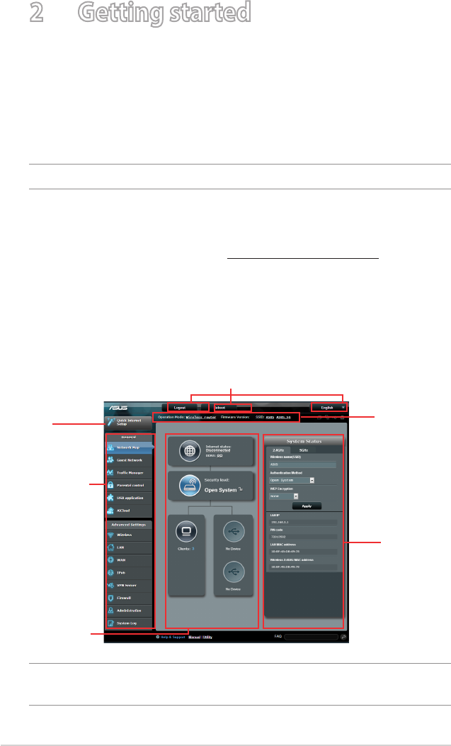
2.1 Logging into the Web GUI
Your ASUS Wireless Router comes with an intuitive web graphical
user interface (GUI) that allows you to easily congure its various
features through a web browser such as Internet Explorer, Firefox,
Safari, or Google Chrome.
NOTE: The features may vary with dierent rmware versions.
To log into the web GUI:
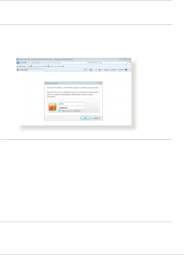
1. On your web browser, enter http://router.asus.com
2. On the login page, key in the default user name (admin) and
password (admin).
3. You can now use the Web GUI to congure various settings of
your ASUS Wireless Router.
NOTE: If you are logging into the Web GUI for the rst time, you will be
directed to the Quick Internet Setup (QIS) page automatically.
Navigation
panel
QIS
Top command buttons
Information
banner
middle
column
right column
15
2.2 Quick Internet Setup (QIS) with Auto-
detection
The Quick Internet Setup (QIS) function guides you in quickly
setting up your Internet connection.
NOTE: When setting the Internet connection for the rst time, press
the Reset button on your wireless router to reset it to its factory default
settings.
To use QIS with auto-detection:
1. Log into the Web GUI. The QIS page launches automatically.
NOTES:
• Bydefault,theloginusernameandpasswordforyourwireless
router's Web GUI is admin. For details on changing your wireless
router's login username and password, refer to section 4.7.2 System.
• Thewirelessrouter'sloginusernameandpasswordisdierentfrom
the 2.4GHz/5GHz network name (SSID) and security key. The wireless
router's login username and password allows you to log into your
wireless router's Web GUI to congure your wireless router's settings.
The 2.4GHz/5GHz network name (SSID) and security key allows Wi-Fi
devices to log in and connect to your 2.4GHz/5GHz network.
16
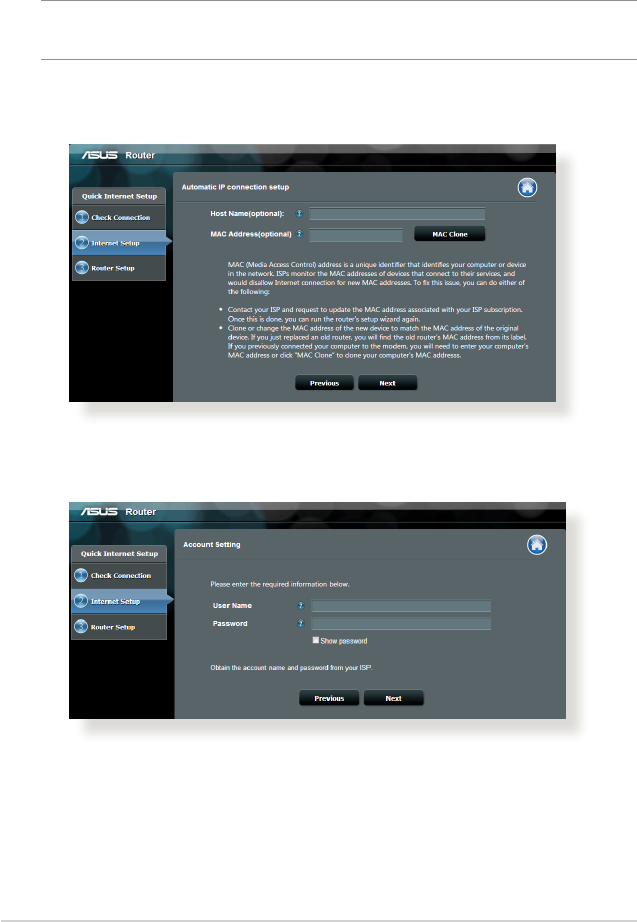
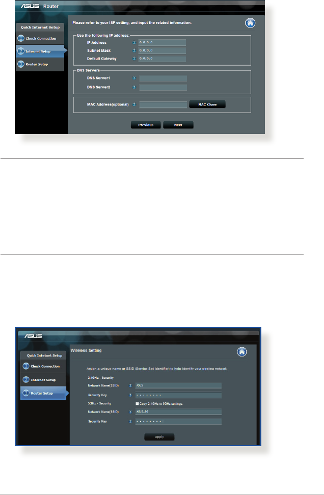
2. The wireless router automatically detects if your ISP connection
type is Dynamic IP, PPPoE, PPTP, L2TP, and Static IP. Key in
the necessary information for your ISP connection type.
IMPORTANT! Obtain the necessary information from your ISP about
the Internet connection type.
for Automatic IP (DHCP)
for PPPoE, PPTP, and L2TP
17
for Static IP
NOTES:
• Theauto-detectionofyourISPconnectiontypetakesplacewhen
you congure the wireless router for the rst time or when your
wireless router is reset to its default settings.
• IfQISfailedtodetectyourInternetconnectiontype,clickSkip to
manual setting and manually congure your connection settings.
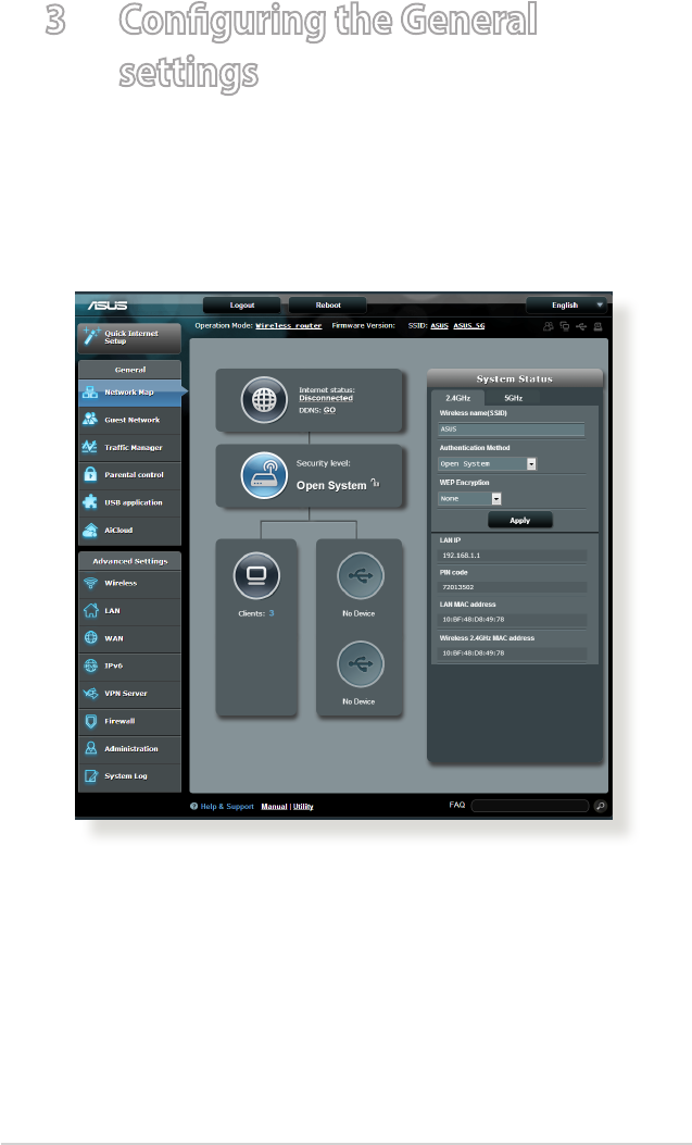
3. Assign the wireless network name (SSID) and security key for
your 2.4GHz and 5 GHz wireless connection. Click Apply when
done.

18
4. Your Internet and wireless settings are displayed. Click Next to
continue.
5. Read the wireless network connection tutorial. When done,
click Finish.

19
2.3 Connecting to your wireless network
After setting up your wireless router via QIS, you can connect your
computer or other smart devices to your wireless network.
To connect to your network:
1. On your computer, click the network icon in the notication
area to display the available wireless networks.
2. Select the wireless network that you want to connect to, then
click Connect.
3. You may need to key in the network security key for a secured
wireless network, then click OK.
4. Wait while your computer establishes connection to the
wireless network successfully. The connection status is
displayed and the network icon displays the connected
status.
NOTES:
• Refertothenextchaptersformoredetailsonconguringyour
wireless network's settings.
• Refertoyourdevice'susermanualformoredetailsonconnectingit
to your wireless network.
20
3 Conguring the General
settings
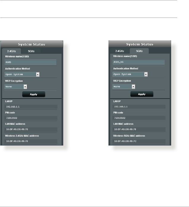
3.1 Using the Network Map
Network Map allows you to congure your network’s security
settings, manage your network clients, and monitor your USB
device.
21
3.1.1 Setting up the wireless security settings
To protect your wireless network from unauthorized access, you
need to configure its security settings.
To set up the wireless security settings:
1. From the navigation panel, go to General > Network Map.
2. On the Network Map screen and under System status, you can
configure the wireless security settings such as SSID, security
level, and encryption settings.
NOTE: You can set up dierent wireless security settings for 2.4GHz and
5GHz bands.
2.4GHz security settings 5GHz security settings
3. On the Wireless name (SSID) field, key in a unique name for
your wireless network.
22
4. From the Security Level dropdown list, select the encryption
method for your wireless network.
IMPORTANT! The IEEE 802.11n/ac standard prohibits using High
Throughput with WEP or WPA-TKIP as the unicast cipher. If you use these
encryption methods, your data rate will drop to IEEE 802.11g 54Mbps
connection.
5. Key in your security passkey.
6. Click Apply when done.
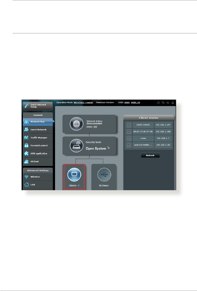
3.1.2 Managing your network clients
To manage your network clients:
1. From the navigation panel, go to General > Network Map tab.
2. On the Network Map screen, select the Client Status icon to
display your network client’s information.
3. To block a client’s access to your network, select the client and
click block.
23
3.1.3 Monitoring your USB device
The ASUS Wireless Router provides two USB 2.0 ports for
connecting USB devices or USB printer to allow you to share files
and printer with clients in your network.
NOTES:
• Tousethisfeature,youneedtoplugaUSBstoragedevice,suchas
a USB hard disk or USB ash drive, to the USB 2.0 port on the rear
panel of your wireless router. Ensure that the USB storage device is
formatted and partitioned properly. Refer to the Plug-n-Share Disk
Support List at
http://event.asus.com/networks/disksupport
• TheUSBportssupporttwoUSBdrivesoroneprinterandoneUSB
drive at the same time.

24
IMPORTANT! You rst need to create a share account and its
permission /access rights to allow other network clients to access the
USB device via an FTP site/third-party FTP client utility, Servers Center,
Samba, or AiCloud. For more details, refer to the section 3.5.Using the
USB Application and 3.6 Using AiCloud in this user manual.
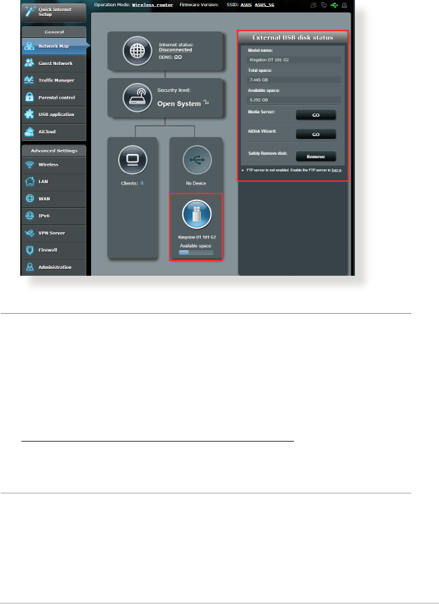
To monitor your USB device:
1. From the navigation panel, go to General > Network Map.
2. On the Network Map screen, select the USB Disk Status icon to
display your USB device’s information.
3. On the AiDisk Wizard field, click GO to set up an FTP server for
Internet file sharing.
NOTES:
• Formoredetails,refertothesection3.5.2 Using Servers Center in
this user manual.
• ThewirelessrouterworkswithmostUSBHDDs/Flashdisks(upto2TB
size) and supports read-write access for FAT16, FAT32, EXT2, EXT3,
and NTFS.
25
Safely removing the USB disk
IMPORTANT: Incorrect removal of the USB disk may cause data
corruption.
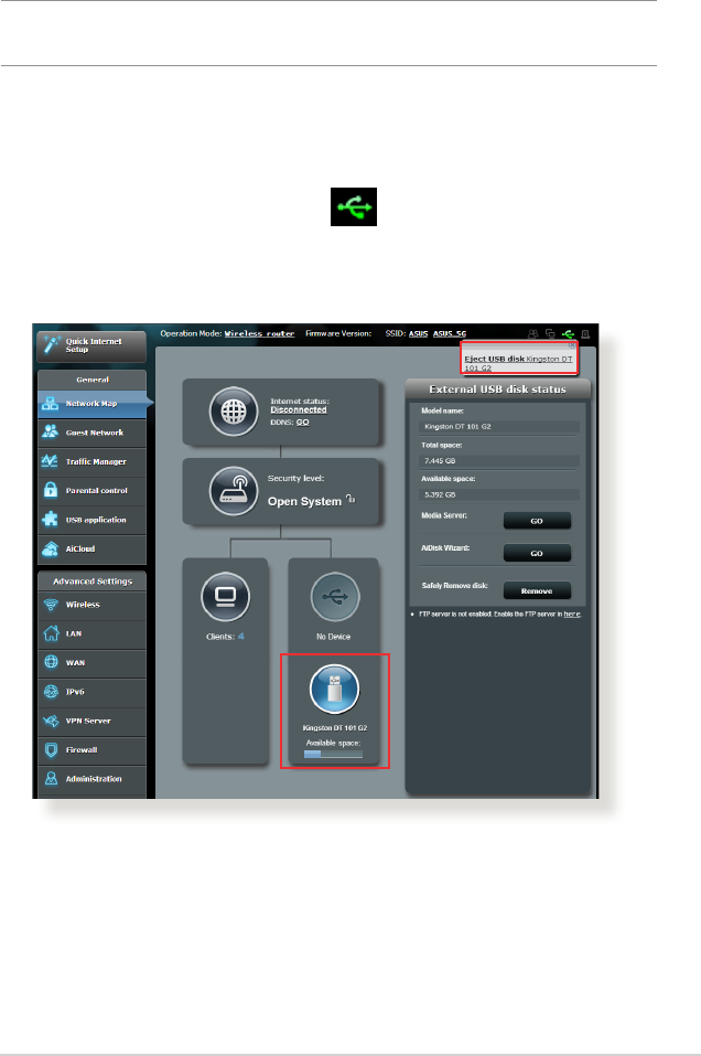
To safely remove the USB disk:
1. From the navigation panel, go to General > Network Map.
2. In the upper right corner, click > Eject USB disk. When
the USB disk is ejected successfully, the USB status shows
Unmounted.
26
3.2 Creating a Guest Network
The Guest Network provides temporary visitors with Internet
connectivity via access to separate SSIDs or networks without
providing access to your private network.
NOTE: RT-AC66U B1 supports up to six SSIDs (three 2.4GHz and three
5GHz SSIDs).
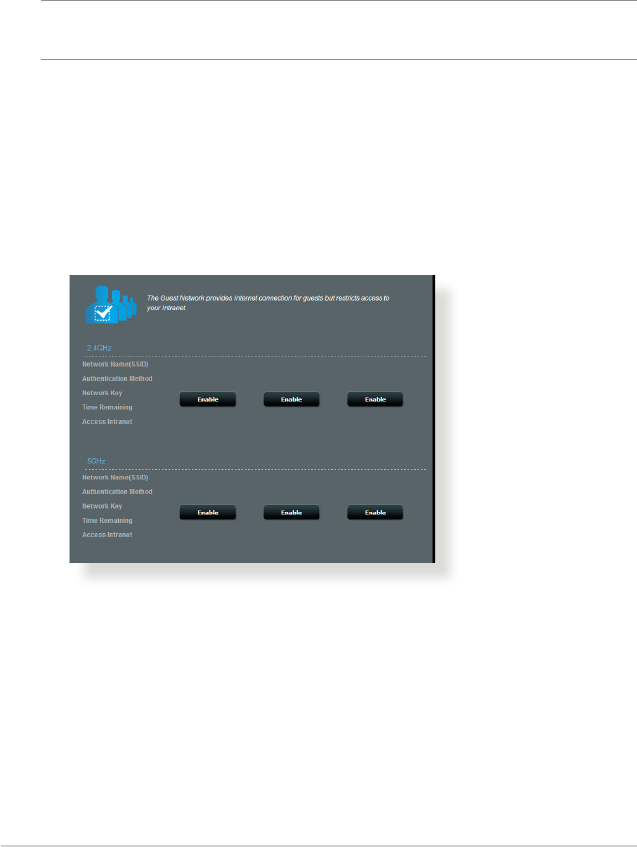
To create a guest network:
1. From the navigation panel, go to General > Guest Network.
2. On the Guest Network screen, select 2.4Ghz or 5Ghz frequency
band for the guest network that you want to create.
3. Click Enable.
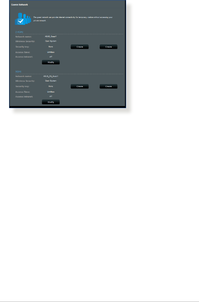
27
4. To congure additional options, click Modify.
5. Click Yes on the Enable Guest Network screen.
6. Assign a wireless name for your temporary network on the
Network Name (SSID) eld.
7. Select an Authentication Method.
8. Select an Encryption method.
9. Specify the Access time or choose Limitless.
10. Select Disable or Enable on the Access Intranet item.
11. When done, click Apply.
28
3.3 Using the Trac Manager
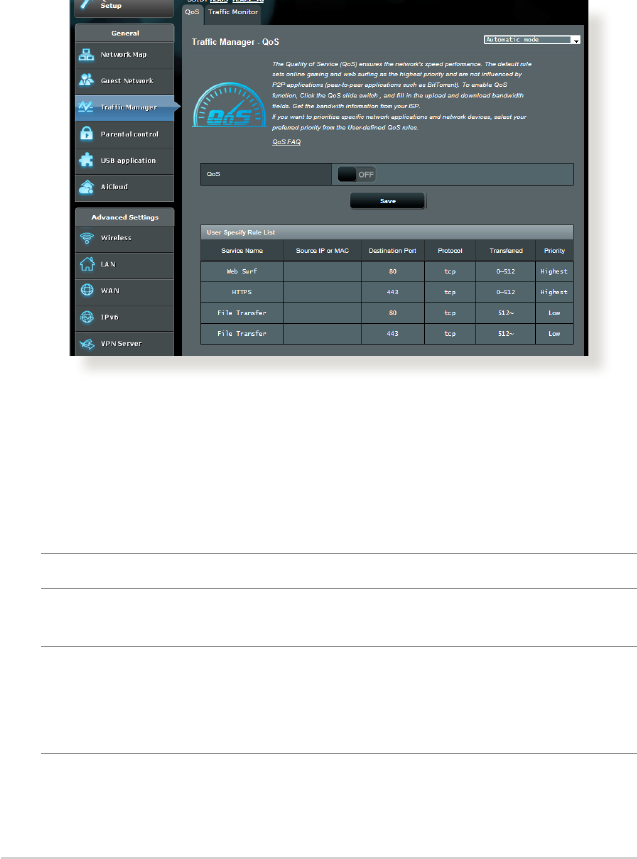
3.3.1 Managing QoS (Quality of Service) Bandwidth
Quality of Service (QoS) allows you to set the bandwidth priority
and manage network trac.
To set up bandwidth priority:
1. From the navigation panel, go to General > Trac Manager >
QoS tab.
2. Click ON to enable QoS. Fill in the upload and download
bandwidth elds.
NOTE: Get the bandwidth information from your ISP.
3. Click Save.
NOTE: The User Specify Rule List is for advanced settings. If you want
to prioritize specic network applications and network services, select
User-dened QoS rules or User-dened Priority from the drop-down
list on the upper-right corner.

29
4. On the user-dened QoS rules page, there are four default
online service types – web surf, HTTPS and le transfers.
Select your preferred service, ll in the Source IP or MAC,
Destination Port, Protocol, Transferred and Priority, then
click Apply. The information will be congured in the QoS rules
screen.
NOTES
• TollinthesourceIPorMAC,youcan:
a) Enter a specic IP address, such as "192.168.122.1".
b) Enter IP addresses within one subnet or within the same IP
pool, such as “192.168.123.*”, or “192.168.*.*”
c) Enter all IP addresses as “*.*.*.*” or leave the eld blank.
d) The format for the MAC address is six groups of two
hexadecimal digits, separated by colons (:), in transmission
order (e.g. 12:34:56:aa:bc:ef)
• Forsourceordestinationportrange,youcaneither:
a) Enter a specic port, such as “95”.
b) Enter ports within a range, such as “103:315”, “>100”, or
“<65535”.
• TheTransferred column contains information about the upstream
and downstream trac (outgoing and incoming network trac) for
one section. In this column, you can set the network trac limit (in
KB) for a specic service to generate specic priorities for the service
assigned to a specic port. For example, if two network clients, PC
1 and PC 2, are both accessing the Internet (set at port 80), but PC 1
exceeds the network trac limit due to some downloading tasks, PC
1 will have a lower priority. If you do not want to set the trac limit,
leave it blank.

30
5. On the User-dened Priority page, you can prioritize the
network applications or devices into ve levels from the user-
dened QoS rules’ dropdown list. Based on priority level, you
can use the following methods to send data packets:
• Changetheorderofupstreamnetworkpacketsthataresent
to the Internet.
• UnderUpload Bandwidth table, set Minimum Reserved
Bandwidth and Maximum Bandwidth Limit for multiple
network applications with dierent priority levels. The
percentages indicate the upload bandwidth rates that are
available for specied network applications.
NOTES:
• Low-prioritypacketsaredisregardedtoensurethetransmissionof
high-priority packets.
• UnderDownload Bandwidth table, set Maximum Bandwidth
Limit for multiple network applications in corresponding order.
The higher priority upstream packet will cause the higher priority
downstream packet.
• Iftherearenopacketsbeingsentfromhigh-priorityapplications,the
full transmission rate of the Internet connection is available for low-
priority packets.
6. Set the highest priority packet. To ensure a smooth online
gaming experience, you can set ACK, SYN, and ICMP as the
highest priority packet.
NOTE: Ensure to enable QoS rst and set up the upload and download
rate limits.
31
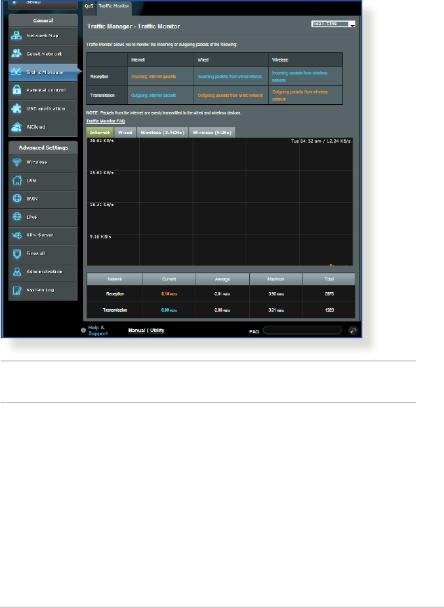
3.3.2 Monitoring Trac
The trac monitor function allows you to access the bandwidth
usage and speed of your Internet, wired, and wireless networks. It
allows you to monitor network trac even on a daily basis.
Note: Packets from the Internet are evenly transmitted to the wired and
wireless devices.
32
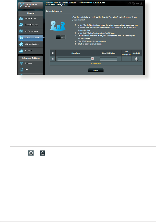
3.4 Setting up Parental Control
Parental Control allows you to control the Internet access time.
Users can set the time limit for a client’s network usage.
To use the parental control function:
1. From the navigation panel, go to General > Parental control.
2. Click ON to enable Parental Control.
3. Select the client whose network usage you want to control.
You may also key in the client’s MAC address in the Client MAC
Address column.
NOTE: Ensure that the client name does not contain special characters
or spaces as this may cause the router to function abnormally.
4. Click or to add or delete the client’s prole.
5. Set up the allowed time limit in Time Management map. Drag
and drop a desired time zone to allow client’s network usage.
6. Click OK.
7. Click Apply to save the settings.
33
3.5 Using the USB Application
The USB Applications function provides AiDisk, Servers Center,
Network Printer Server and Download Master submenus.
IMPORTANT! To use the server functions, you need to insert a USB
storage device, such as a USB hard disk or USB ash drive, in the USB
2.0 port on the rear panel of your wireless router. Ensure that the USB
storage device is formatted and partitioned properly. Refer to the ASUS
website at http://event.asus.com/2009/networks/disksupport/ for the
le system support table.
3.5.1 Using AiDisk
AiDisk allows you to share les stored on a connected USB device
through the Internet. AiDisk also assists you with setting up ASUS
DDNS and an FTP server.
To use AiDisk:
1. From the navigation panel, go to General > USB application,
then click the AiDisk icon.
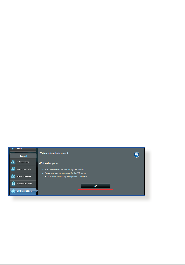
2. From the Welcome to AiDisk wizard screen, click Go.
34
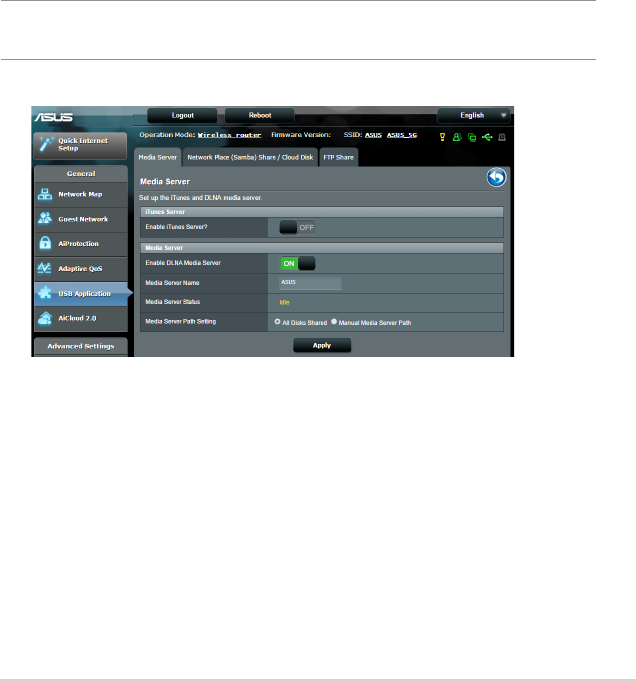
4. Create your domain name via the ASUS DDNS services, read
the Terms of Service and then select I will use the service and
accept the Terms of service and key in your domain name.
When done, click Next.
You can also select Skip ASUS DDNS settings then click Next
to skip the DDNS setting.
5. Click Finish to complete the setting.
6. To access the FTP site that you created, launch a web browser
or a third-party FTP client utility and key in the ftp link
(ftp://<domain name>.asuscomm.com) you have previously
created.
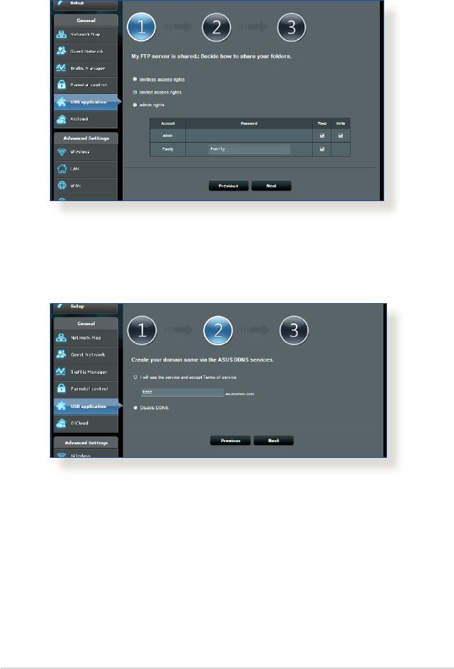
3. Select the access rights that you want to assign to the clients
accessing your shared data.
35
3.5.2 Using Servers Center
Servers Center allows you to share the media les from the USB
disk via a Media Server directory, Samba share service, or FTP
share service. You can also congure other settings for the USB
disk in the Servers Center.
Using Media Server
Your wireless router allows DLNA-supported devices to access
multimedia les from the USB disk connected to your wireless
router.
NOTE: Before using the DLNA Media Server function, connect your
device to the RT-AC88U’s network.
36
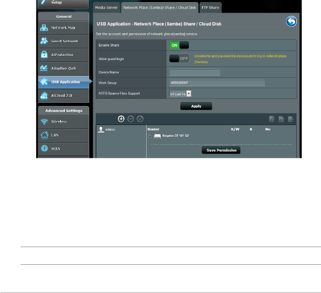
To launch the Media Server setting page, go to General > USB
application > Media Services and Servers > Media Servers tab.
Refer to the following for the descriptions of the elds:
• Enable iTunes Server?: Select ON/OFF to enable/disable the
iTunes Server.
• Enable DLNA Media Server: Select ON/OFF to enable/
disable the DLNA Media Server.
• Media Server Status: Displays the status of the media server.
• Media Server Path Setting: Select All Disks Shared or
Manual Media Server Path.
Using Network Place (Samba) Share service
Network Place (Samba) Share allows you to set up the accounts
and permissions for the Samba service.
To use Samba share:
1. From the navigation panel, go to General > USB application >
Media Services and Servers > Network Place (Samba) Share
/ Cloud Disk tab.
NOTE: Network Place (Samba) Share is enabled by default.
37
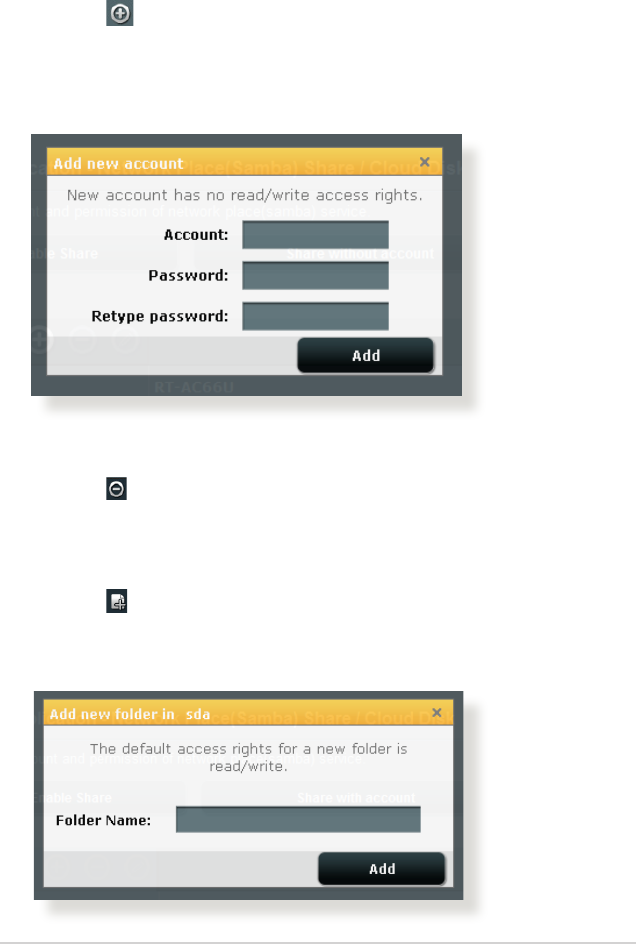
To delete an existing account:
a) Select the account that you want to delete.
b) Click .
c) When prompted, click Delete to conrm the account
deletion.
To add a folder:
a) Click .
b) Enter the folder name, and click Add. The folder that you
created will be added to the folder list.
2. Follow the steps below to add, delete, or modify an account.
To create a new account:
a) Click to add new account.
b) In the Account and Password elds, key in the name and
password of your network client. Retype the password to
conrm. Click Add to add the account to the list.
38
3. From the list of folders, select the type of access permission
that you want to assign for specic folders:
• R/W: Select this option to assign read/write access.
• R: Select this option to assign read-only access.
• No: Select this option if you do not want to share a specic
le folder.
4. Click Apply to apply the changes.
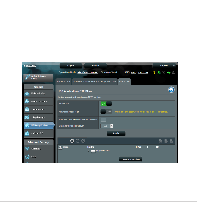
Using the FTP Share service
FTP share enables an FTP server to share les from USB disk to
other devices via your local area network or via the Internet.
IMPORTANT:
• EnsurethatyousafelyremovetheUSBdisk.Incorrectremovalofthe
USB disk may cause data corruption.
• TosafelyremovetheUSBdisk,refertothesectionSafely removing
the USB disk under 3.1.3 Monitoring your USB device.

39
To use FTP Share service:
NOTE: Ensure that you have set up your FTP server through
AiDisk. For more details, refer to the section 3.5.1 Using AiDisk.
1. From the navigation panel, click General > USB application >
Media Services and Servers > FTP Share tab.
2. From the list of folders, select the type of access rights that you
want to assign for specic folders:
• R/W: Select to assign read/write access for a specic folder.
• W: Select to assign write only access for a specic folder.
• R: Select to assign read only access for a specic folder.
• No: Select this option if you do not want to share a specic
folder.
3. If you prefer, you can set the Allow anonymous login eld to
ON.
4. In the Maximum number of concurrent connections eld,
key in the number of devices that can simultaneously connect
to the FTP share server.
5. Click Apply to conrm the changes.
6. To access the FTP server, key in the ftp link
ftp://<hostname>.asuscomm.com and your user name and
password on a web browser or a third-party FTP utility.

40
3.5.3 3G/4G
3G/4G USB modems can be connected to RT-AC88U to allow
Internet access.
NOTE: For a list of veried USB modems, please visit:
http://event.asus.com/2009/networks/3gsupport/
To set up 3G/4G internet access:
1. From the navigation panel, click General > USB application >
3G/4G.
2. In the Enable USB Modem eld, select Ye s.
3. Set up the following:
• Location: Select your 3G/4G service provider’s location from
the dropdown list.
• ISP: Select your Internet Service Provider (ISP) from the
dropdown list.
• APN (Access Point Name) service (optional): Contact your
3G/4G service provider for detailed information.
• Dial Number and PIN code: The 3G/4G provider’s access
number and PIN code for connection.
NOTE: PIN code may vary from dierent providers.
• Username / Password: The username and password will be
provided by the 3G/4G network carrier.
• USB Adapter: Choose your USB 3G / 4G adapter from the
dropdown list. If you are not sure of your USB adapter’s
model or the model is not listed in the options, select Auto.
4. Click Apply.
NOTE: The router will reboot for the settings to take eect.
41
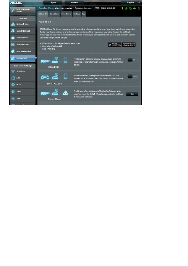
3.6 Using AiCloud 2.0
AiCloud 2.0 is a cloud service application that allows you to save,
sync, share, and access your les.
To use AiCloud:
1. From Google Play Store or Apple Store, download and install
the ASUS AiCloud app to your smart device.
2. Connect your smart device to your network. Follow the
instructions to complete the AiCloud setup process.
42
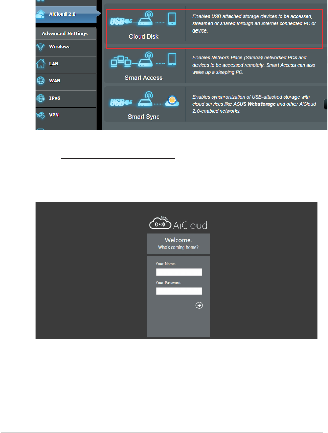
3.6.1 Cloud Disk
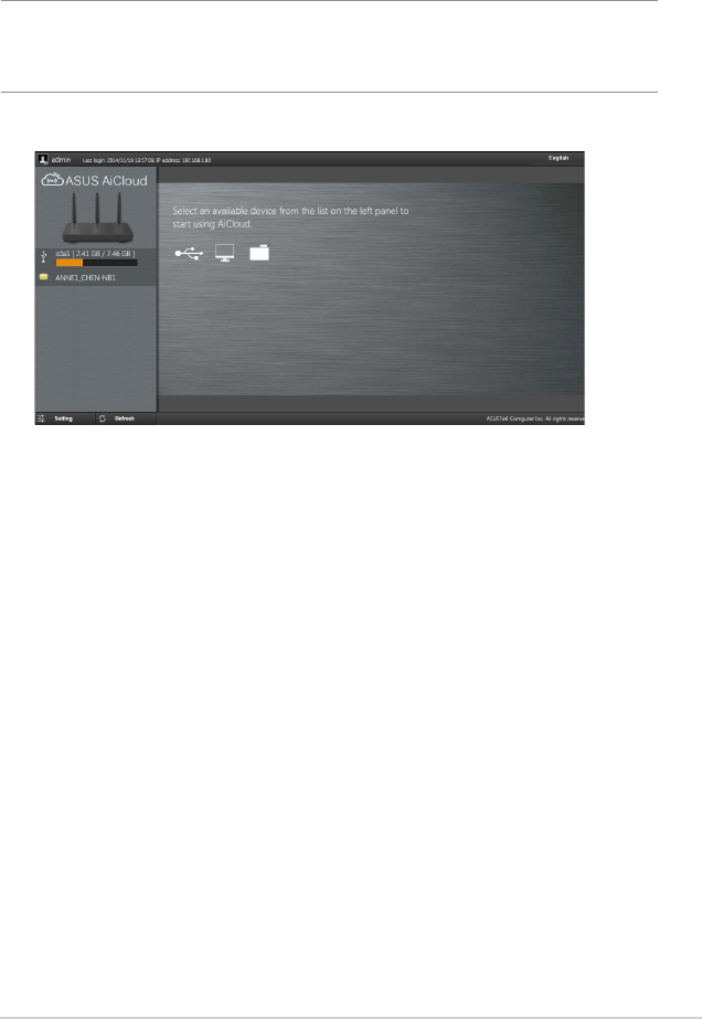
To create a cloud disk:
1. Insert a USB storage device into the wireless router.
2. Turn on Cloud Disk.
3. Go to https://router.asus.com and enter the router login
account and password. For better user experience, we
recommend that you use Google Chrome or Firefox.
43
4. You can now start accessing Cloud Disk les on devices
connected to the network.
NOTE: When accessing the devices that are connected to the network,
you need to enter the device’s user name and password manually, which
will not be saved by AiCloud for security reason.
44
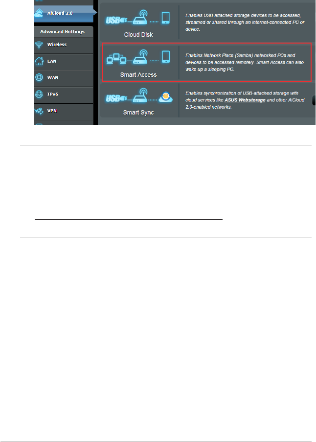
3.6.2 Smart Access
The Smart Access function allows you to easily access your home
network via your router’s domain name.
NOTES:
• YoucancreateadomainnameforyourrouterwithASUSDDNS.For
more details, refer to section 4.3.5 DDNS.
• Bydefault,AiCloudprovidesasecureHTTPSconnection.Keyin
https://[yourASUSDDNSname].asuscomm.com for a very secure
Cloud Disk and Smart Access usage.

45
3.6.3 Smart Sync
To use Smart Sync:
1. Launch AiCloud, click Smart Sync > Go.
2. Select ON to enable Smart Sync.
3. Click Add new account.
4. Enter your ASUS WebStorage account password and select the
directory that you want to sync with WebStorage.
5. Click Apply.
46
4 Conguring the Advanced
Settings
4.1 Wireless
4.1.1 General
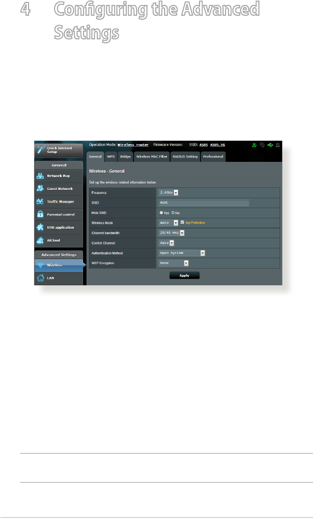
The General tab allows you to congure the basic wireless
settings.
To congure the basic wireless settings:
1. From the navigation panel, go to Advanced Settings >
Wireless > General tab.
2. Select 2.4GHz or 5GHz as the frequency band for your wireless
network.
3. Assign a unique name containing up to 32 characters for your
SSID (Service Set Identier) or network name to identify your
wireless network. Wi-Fi devices can identify and connect to
the wireless network via your assigned SSID. The SSIDs on the
information banner are updated once new SSIDs are saved to
the settings.
NOTE: You can assign unique SSIDs for the 2.4 GHz and 5GHz frequency
bands.

47
4. In the Hide SSID eld, select Ye s to prevent wireless devices
from detecting your SSID. When this function is enabled, you
would need to enter the SSID manually on the wireless device
to access the wireless network.
5. Select any of these wireless mode options to determine the
types of wireless devices that can connect to your wireless
router:
• Auto: Select Auto to allow 802.11AC, 802.11n, 802.11g, and
802.11b devices to connect to the wireless router.
• Legacy: Select Legacy to allow 802.11b/g/n devices to
connect to the wireless router. Hardware that supports
802.11n natively, however, will only run at a maximum speed
of 54Mbps.
• N only: Select N only to maximize wireless N performance.
This setting prevents 802.11g and 802.11b devices from
connecting to the wireless router.
6. Select the operating channel for your wireless router. Select
Auto to allow the wireless router to automatically select the
channel that has the least amount of interference.
7. Select any of these channel bandwidth to accommodate higher
transmission speeds:
40MHz: Select this bandwidth to maximize the wireless
throughput.
20MHz (default): Select this bandwidth if you encounter some
issues with your wireless connection.
8. Select any of these authentication methods:
• Open System: This option provides no security.
• Shared Key: You must use WEP encryption and enter at least
one shared key.

48
• WPA/WPA2 Personal/WPA Auto-Personal: This option
provides strong security. You can use either WPA (with
TKIP) or WPA2 (with AES). If you select this option, you must
use TKIP + AES encryption and enter the WPA passphrase
(network key).
• WPA/WPA2 Enterprise/WPA Auto-Enterprise: This option
provides very strong security. It is with integrated EAP server
or an external RADIUS back-end authentication server.
• Radius with 802.1x
NOTE: Your wireless router supports the maximum transmission rate
of 54Mbps when the Wireless Mode is set to Auto and encryption
method is WEP or TKIP.
9. Select any of these WEP (Wired Equivalent Privacy) Encryption
options for the data transmitted over your wireless network:
• O: Disables WEP encryption
• 64-bit: Enables weak WEP encryption
• 128-bit: Enables improved WEP encryption.
10.When done, click Apply.
49
4.1.2 WPS
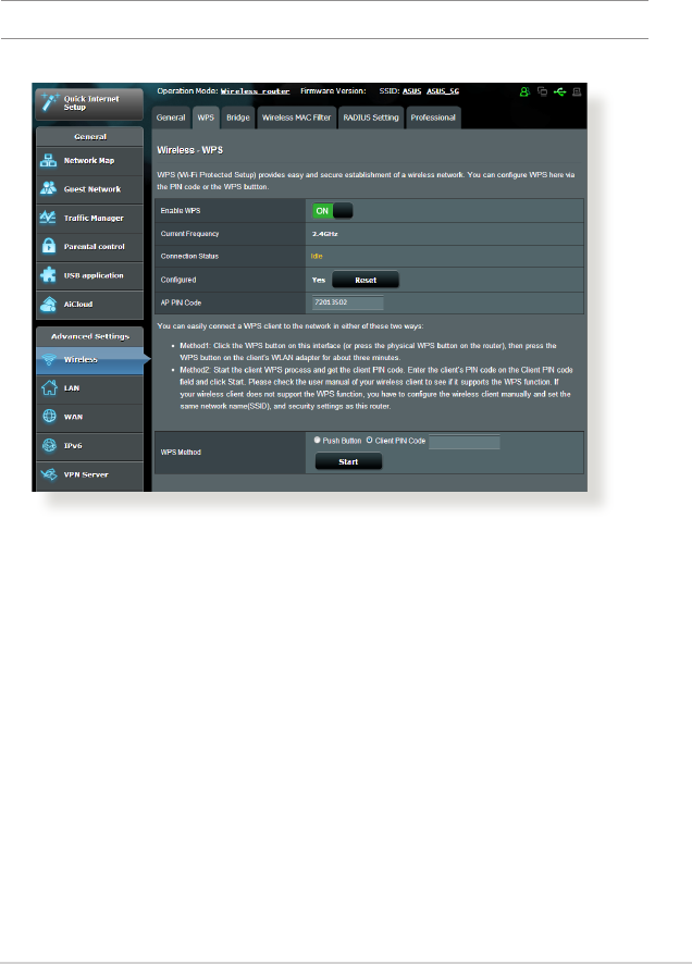
WPS (Wi-Fi Protected Setup) is a wireless security standard that
allows you to easily connect devices to a wireless network. You
can congure the WPS function via the PIN code or WPS button.
NOTE: Ensure that the devices support WPS.
To enable WPS on your wireless network:
1. From the navigation panel, go to Advanced Settings >
Wireless > WPS tab.
2. In the Enable WPS eld, move the slider to ON.
3. WPS uses 2.4GHz by default. If you want to change the
frequency to 5GHz, turn OFF the WPS function, click Switch
Frequency in the Current Frequency eld, and turn WPS ON
again.

50
Note: WPS supports authentication using Open System, WPA-Personal,
and WPA2-Personal. WPS does not support a wireless network that uses
a Shared Key, WPA-Enterprise, WPA2-Enterprise, and RADIUS encryption
method.
3. In the WPS Method eld, select Push Button or Client PIN
code. If you select Push Button, go to step 4. If you select
Client PIN code, go to step 5.
4. To set up WPS using the router’s WPS button, follow these
steps:
a. Click Start or press the WPS button found at the rear of the
wireless router.
b. Press the WPS button on your wireless device. This is
normally identied by the WPS logo.
Note: Check your wireless device or its user manual for the location of
the WPS button.
c. The wireless router will scan for any available WPS devices.
If the wireless router does not nd any WPS devices, it will
switch to standby mode.
5. To set up WPS using the Client’s PIN code, follow these steps:
a. Locate the WPS PIN code on your wireless device’s user
manual or on the device itself.
b. Key in the Client PIN code on the text box.
c. Click Start to put your wireless router into WPS survey mode.
The router’s LED indicators quickly ash three times until the
WPS setup is completed.
51
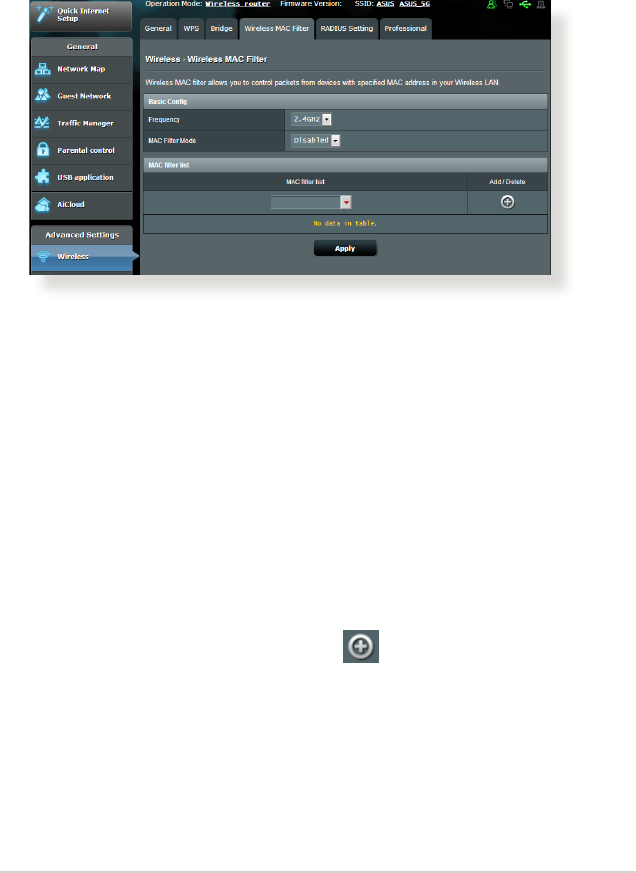
4.1.3 Wireless MAC Filter
Wireless MAC lter provides control over packets transmitted to
a specied MAC (Media Access Control) address on your wireless
network.
To set up the Wireless MAC lter:
1. From the navigation panel, go to Advanced Settings >
Wireless > Wireless MAC Filter tab.
2. In the Frequency eld, select the frequency band that you
want to use for the Wireless MAC lter.
3. In the MAC Filter Mode dropdown list, select either Accept or
Reject.
• SelectAccept to allow devices in the MAC lter list to access
to the wireless network.
• SelectReject to prevent devices in the MAC lter list to
access to the wireless network.
4. On the MAC lter list, click the Add button and key in the
MAC address of the wireless device.
5. Click Apply.
52
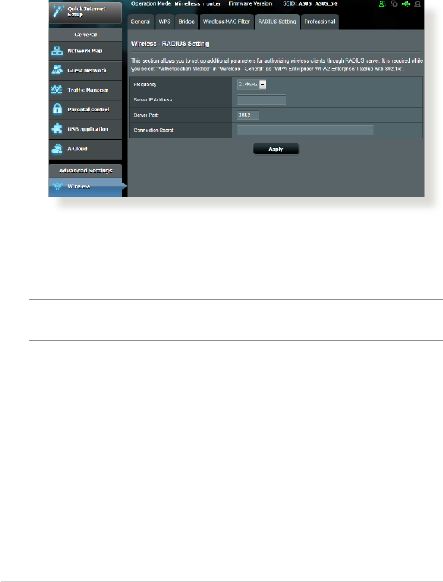
4.1.4 RADIUS Setting
RADIUS (Remote Authentication Dial In User Service) Setting
provides an extra layer of security when you choose WPA-
Enterprise, WPA2-Enterprise, or Radius with 802.1x as your
Authentication Mode.
To set up wireless RADIUS settings:
1. Ensure that the wireless router’s authentication mode is set to
WPA-Enterprise, WPA2-Enterprise, or Radius with 802.1x.
NOTE: Please refer to section 4.1.1 General section for conguring your
wireless router’s Authentication Mode.
2. From the navigation panel, go to Advanced Settings >
Wireless > RADIUS Setting.
3. Select the frequency band.
4. In the Server IP Address eld, key in your RADIUS server’s IP
Address.
5. In the Connection Secret eld, assign the password to access
your RADIUS server.
6. Click Apply.
53
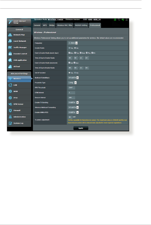
In the Professional Settings screen, you can congure the
following:
• Frequency: Select the frequency band that the professional
settings will be applied to.
• Enable Radio: Select Yes to enable wireless networking.
Select No to disable wireless networking.
• Date to Enable Radio (weekdays): You can specify which
days of the week wireless networking is enabled.
• Time of Day to Enable Radio: You can specify a time range
when wireless networking is enabled during the week.
4.1.5 Professional
The Professional screen provides advanced conguration options.
NOTE: We recommend that you use the default values on this page.

54
• Date to Enable Radio (weekend): You can specify which
days of the weekend wireless networking is enabled.
• Time of Day to Enable Radio: You can specify a time range
when wireless networking is enabled during the weekend.
• Set AP isolated: The Set AP isolated item prevents wireless
devices on your network from communicating with each
other. This feature is useful if many guests frequently join or
leave your network. Select Yes to enable this feature or select
No to disable.
• Multicast rate (Mbps): Select the multicast transmission
rate or click Disable to switch o simultaneous single
transmission.
• Preamble Type: Preamble Type denes the length of time
that the router spent for CRC (Cyclic Redundancy Check). CRC
is a method of detecting errors during data transmission.
Select Short for a busy wireless network with high network
trac. Select Long if your wireless network is composed of
older or legacy wireless devices.
• RTS Threshold: Select a lower value for RTS (Request to
Send) Threshold to improve wireless communication in a
busy or noisy wireless network with high network trac and
numerous wireless devices.
• DTIM Interval: DTIM (Delivery Trac Indication Message)
Interval or Data Beacon Rate is the time interval before a
signal is sent to a wireless device in sleep mode indicating
that a data packet is awaiting delivery. The default value is
three milliseconds.
• Beacon Interval: Beacon Interval is the time between one
DTIM and the next. The default value is 100 milliseconds.
Lower the Beacon Interval value for an unstable wireless
connection or for roaming devices.
• Enable TX Bursting: Enable TX Bursting improves
transmission speed between the wireless router and 802.11g
devices.
55
• Wireless multicast forwarding: Select Enable to allow the
wireless router to forward multicast trac to other wireless
devices that support multicast. Select Disable to prevent the
router from forwarding multicast transmissions.
• Enable WMM APSD: Enable WMM APSD (Wi-Fi Multimedia
Automatic Power Save Delivery) to improve power
management between wireless devices. Select Disable to
switch o WMM APSD.
• TX Power adjustment: TX Power adjustment refers to the
milliWatts (mW) needed to power the radio signal output of
the wireless router. Enter a value between 0 to 100.
NOTE: Increasing the TX Power adjustment values may aect the
stability of the wireless network.
4.2 LAN
4.2.1 LAN IP
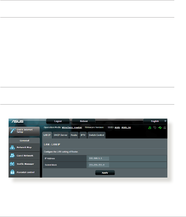
The LAN IP screen allows you to modify the LAN IP settings of your
wireless router.
NOTE: Any changes to the LAN IP address will be reected on your
DHCP settings.
56
To modify the LAN IP settings:
1. From the navigation panel, go to Advanced Settings > LAN >
LAN IP tab.
2. Modify the IP address and Subnet Mask.
3. When done, click Apply.
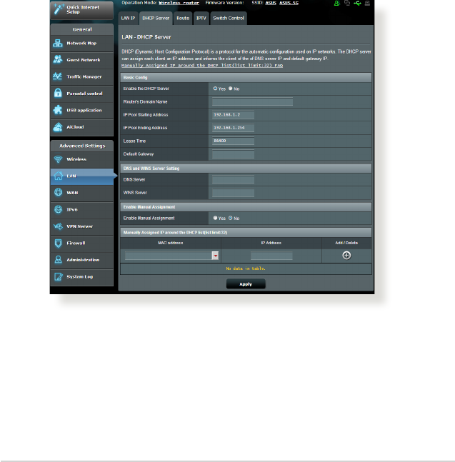
4.2.2 DHCP Server
Your wireless router uses DHCP to assign IP addresses
automatically on your network. You can specify the IP address
range and lease time for the clients on your network.
To congure the DHCP server:
1. From the navigation panel, go to Advanced Settings > LAN >
DHCP Server tab.
2. In the Enable the DHCP Server eld, tick Yes.

57
3. In the Domain Name text box, enter a domain name for the
wireless router.
4. In the IP Pool Starting Address eld, key in the starting IP
address.
5. In the IP Pool Ending Address eld, key in the ending IP
address.
6. In the Lease Time eld, specify in seconds when an assigned
IP address will expire. Once it reaches this time limit, the DHCP
server will then assign a new IP address.
NOTES:
• We recommend that you use an IP address format of 192.168.1.xxx
(where xxx can be any number between 2 and 254) when specifying
an IP address range.
• AnIPPoolStartingAddressshouldnotbegreaterthantheIPPool
Ending Address.
7. In the DNS and Server Settings section, key in your DNS
Server and WINS Server IP address if needed.
8. Your wireless router can also manually assign IP addresses to
devices on the network. On the Enable Manual Assignment
eld, choose Yes to assign an IP address to specic MAC
addresses on the network. Up to 32 MAC Addresses can be
added to the DHCP list for manual assignment.
58
4.2.3 Route
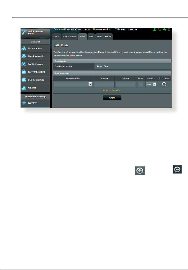
If your network makes use of more than one wireless router, you
can congure a routing table to share the same Internet service.
NOTE: We recommend that you do not change the default route
settings unless you have advanced knowledge of routing tables.
To congure the LAN Routing table:
1. From the navigation panel, go to Advanced Settings > LAN >
Route tab.
2. On the Enable static routes eld, choose Yes.
3. On the Static Route List, enter the network information of
other access points or nodes. Click the Add or Delete
button to add or remove a device on the list.
4. Click Apply.
59
4.2.4 IPTV
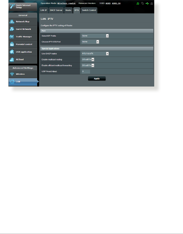
The wireless router supports connection to IPTV services through
an ISP or a LAN. The IPTV tab provides the conguration settings
needed to set up IPTV, VoIP, multicasting, and UDP for your
service. Contact your ISP for specic information regarding your
service.
60
4.3 WAN
4.3.1 Internet Connection
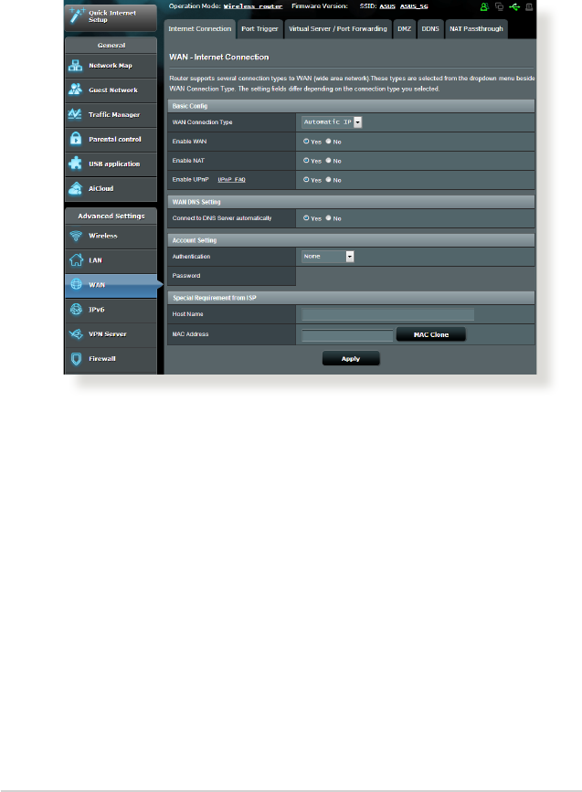
The Internet Connection screen allows you to congure the
settings of various WAN connection types.
To congure the WAN connection settings:
1. From the navigation panel, go to Advanced Settings > WAN >
Internet Connection tab.
2. Congure the following settings below. When done, click
Apply.
• WAN Connection Type: Choose your Internet Service Provider
type. The choices are Automatic IP, PPPoE, PPTP, L2TP or
xed IP. Consult your ISP if the router is unable to obtain a
valid IP address or if you are unsure the WAN connection type.
• Enable WAN: Select Yes to allow the router Internet access.
Select No to disable Internet access.

61
• Enable NAT: NAT (Network Address Translation) is a system
where one public IP (WAN IP) is used to provide Internet
access to network clients with a private IP address in a LAN.
The private IP address of each network client is saved in a NAT
table and is used to route incoming data packets.
• Enable UPnP: UPnP (Universal Plug and Play) allows several
devices (such as routers, televisions, stereo systems, game
consoles, and cellular phone), to be controlled via an IP-based
network with or without a central control through a gateway.
UPnP connects PCs of all form factors, providing a seamless
network for remote conguration and data transfer. Using
UPnP, a new network device is discovered automatically.
Once connected to the network, devices can be remotely
congured to support P2P applications, interactive gaming,
video conferencing, and web or proxy servers. Unlike Port
forwarding, which involves manually conguring port
settings, UPnP automatically congures the router to accept
incoming connections and direct requests to a specic PC on
the local network.
• Connect to DNS Server: Allows this router to get the DNS
IP address from the ISP automatically. A DNS is a host on
the Internet that translates Internet names to numeric IP
addresses.
• Authentication: This item may be specied by some ISPs.
Check with your ISP and ll them in if required.
• Host Name: This eld allows you to provide a host name for
your router. It is usually a special requirement from your ISP.
If your ISP assigned a host name to your computer, enter the
host name here.

62
• MAC Address: MAC (Media Access Control) address is a
unique identier for your networking device. Some ISPs
monitor the MAC address of networking devices that connect
to their service and reject any unrecognized device that
attempt to connect. To avoid connection issues due to an
unregistered MAC address, you can:
• ContactyourISPandupdatetheMACaddressassociated
with your ISP service.
• CloneorchangetheMACaddressoftheASUSwirelessrouter
to match the MAC address of the previous networking device
recognized by the ISP.
63
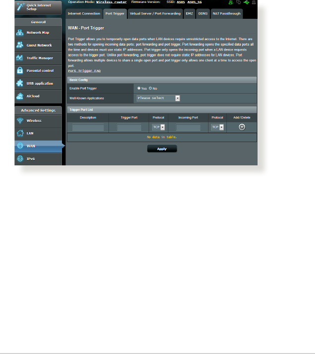
4.3.2 Port Trigger
Port range triggering opens a predetermined incoming port for a
limited period of time whenever a client on the local area network
makes an outgoing connection to a specied port. Port triggering
is used in the following scenarios:
• More than one local client needs port forwarding for the
same application at a dierent time.
• An application requires specic incoming ports that are
dierent from the outgoing ports.
To set up Port Trigger:
1. From the navigation panel, go to Advanced Settings > WAN >
Port Trigger tab.
2. Congure the following settings below. When done, click
Apply.
• Enable Port Trigger: Choose Yes to enable Port Trigger.
• Well-Known Applications: Select popular games and web
services to add to the Port Trigger List.
• Description: Enter a short name or description for the service.

64
• Trigger Port: Specify a trigger port to open the incoming port.
• Protocol: Select the protocol, TCP, or UDP.
• Incoming Port: Specify an incoming port to receive inbound
data from the Internet.
• Protocol: Select the protocol, TCP, or UDP.
NOTES:
• WhenconnectingtoanIRCserver,aclientPCmakesanoutgoing
connection using the trigger port range 66660-7000. The IRC server
responds by verifying the username and creating a new connection
to the client PC using an incoming port.
• IfPortTriggerisdisabled,therouterdropstheconnectionbecause
it is unable to determine which PC is requesting for IRC access.
When Port Trigger is enabled, the router assigns an incoming port to
receive the inbound data. This incoming port closes once a specic
time period has elapsed because the router is unsure when the
application has been terminated.
• Porttriggeringonlyallowsoneclientinthenetworktousea
particular service and a specic incoming port at the same time.
• Youcannotusethesameapplicationtotriggeraportinmorethan
one PC at the same time. The router will only forward the port back
to the last computer to send the router a request/trigger.
65
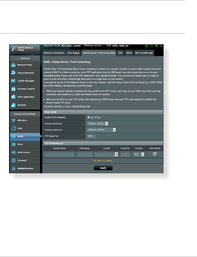
4.3.3 Virtual Server/Port Forwarding
Port forwarding is a method to direct network trac from the
Internet to a specic port or a specic range of ports to a device
or number of devices on your local network. Setting up Port
Forwarding on your router allows PCs outside the network to
access specic services provided by a PC in your network.
NOTE: When port forwarding is enabled, the ASUS router blocks
unsolicited inbound trac from the Internet and only allows replies
from outbound requests from the LAN. The network client does not
have access to the Internet directly, and vice versa.
To set up Port Forwarding:
1. From the navigation panel, go to Advanced Settings > WAN >
Virtual Server / Port Forwarding tab.

66
2. Congure the following settings below. When done, click
Apply.
• Enable Port Forwarding: Choose Yes to enable Port
Forwarding.
• Famous Server List: Determine which type of service you
want to access.
• Famous Game List: This item lists ports required for popular
online games to work correctly.
• FTP Server Port: Avoid assigning the port range 20:21 for
your FTP server as this would conict with the router’s native
FTP server assignment.
• Service Name: Enter a service name.
• Port Range: If you want to specify a Port Range for clients
on the same network, enter the Service Name, the Port
Range (e.g. 10200:10300), the LAN IP address, and leave the
Local Port empty. Port range accepts various formats such
as Port Range (300:350), individual ports (566,789) or Mix
(1015:1024,3021).
NOTES:
• Whenyournetwork’srewallisdisabledandyouset80astheHTTP
server’s port range for your WAN setup, then your http server/web
server would be in conict with the router’s web user interface.
• Anetworkmakesuseofportsinordertoexchangedata,witheach
port assigned a port number and a specic task. For example, port 80
is used for HTTP. A specic port can only be used by one application
or service at a time. Hence, two PCs attempting to access data
through the same port at the same time would fail. For example, you
cannot set up Port Forwarding for port 100 for two PCs at the same
time.

67
• Local IP: Key in the client’s LAN IP address.
NOTE: Use a static IP address for the local client to make port forwarding
work properly. Refer to section 4.2 LAN for information.
• Local Port: Enter a specic port to receive forwarded packets.
Leave this eld blank if you want the incoming packets to be
redirected to the specied port range.
• Protocol: Select the protocol. If you are unsure, select BOTH.
To check if Port Forwarding has been congured successfully:
• Ensure that your server or application is set up and running.
• You will need a client outside your LAN but has Internet
access (referred to as “Internet client”). This client should not
be connected to the ASUS router.
• On the Internet client, use the router’s WAN IP to access the
server. If port forwarding has been successful, you should be
able to access the les or applications.
Dierences between port trigger and port forwarding:
• Port triggering will work even without setting up a specic
LAN IP address. Unlike port forwarding, which requires a
static LAN IP address, port triggering allows dynamic port
forwarding using the router. Predetermined port ranges are
congured to accept incoming connections for a limited
period of time. Port triggering allows multiple computers
to run applications that would normally require manually
forwarding the same ports to each PC on the network.
• Port triggering is more secure than port forwarding since the
incoming ports are not open all the time. They are opened
only when an application is making an outgoing connection
through the trigger port.

68
4.3.4 DMZ
Virtual DMZ exposes one client to the Internet, allowing this
client to receive all inbound packets directed to your Local Area
Network.
Inbound trac from the Internet is usually discarded and routed
to a specic client only if port forwarding or a port trigger has
been congured on the network. In a DMZ conguration, one
network client receives all inbound packets.
Setting up DMZ on a network is useful when you need incoming
ports open or you want to host a domain, web, or e-mail server.
Caution: Opening all the ports on a client to the Internet makes the
network vulnerable to outside attacks. Please be aware of the security
risks involved in using DMZ.
To set up DMZ:
1. From the navigation panel, go to Advanced Settings > WAN >
DMZ tab.
2. Congure the setting below. When done, click Apply.
• IP address of Exposed Station: Key in the client’s LAN IP
address that will provide the DMZ service and be exposed
on the Internet. Ensure that the server client has a static IP
address.
To remove DMZ:
1. Delete the client’s LAN IP address from the IP Address of
Exposed Station text box.
2. When done, click Apply.
69
4.3.5 DDNS
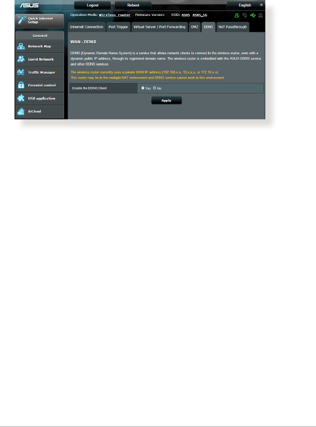
Setting up DDNS (Dynamic DNS) allows you to access the router
from outside your network through the provided ASUS DDNS
Service or another DDNS service.
To set up DDNS:
1. From the navigation panel, go to Advanced Settings > WAN >
DDNS tab.
2. Congure the following settings below. When done, click
Apply.
• Enable the DDNS Client: Enable DDNS to access the ASUS
router via the DNS name rather than WAN IP address.
• Server and Host Name: Choose ASUS DDNS or other DDNS.
If you want to use ASUS DDNS, ll in the Host Name in the
format of xxx.asuscomm.com (xxx is your host name).
• If you want to use a dierent DDNS service, click FREE TRIAL
and register online rst. Fill in the User Name or E-mail
Address and Password or DDNS Key elds.
70
• Enable wildcard: Enable wildcard if your DDNS service
requires one.
NOTES:
DDNS service will not work under these conditions:
• WhenthewirelessrouterisusingaprivateWANIPaddress(192.168.
x.x, 10.x.x.x, or 172.16.x.x), as indicated by a yellow text.
• TheroutermaybeonanetworkthatusesmultipleNATtables.
4.3.6 NAT Passthrough
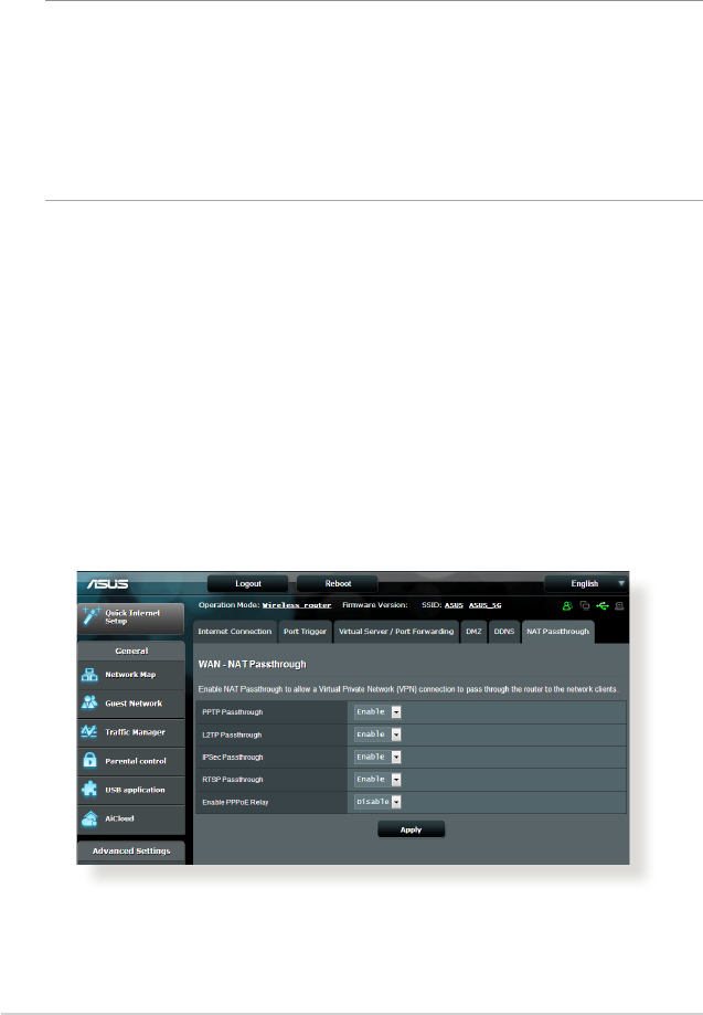
NAT Passthrough allows a Virtual Private Network (VPN)
connection to pass through the router to the network clients.
PPTP Passthrough, L2TP Passthrough, IPsec Passthrough and RTSP
Passthrough are enabled by default.
To enable / disable the NAT Passthrough settings, go to the
Advanced Settings > WAN > NAT Passthrough tab. When done,
click Apply.