ASUSTeK Computer RTG32 Broad range wireless family router User Manual
ASUSTeK Computer Inc Broad range wireless family router
UserManual.wiki
>
ASUSTeK Computer
>
RTG32 User Manual
User manual
Navigation menu
Upload a User Manual
Namespaces
Wiki Guide
HTML
PDF
Info
Views
User Manual
Discussion / Help
Navigation
![5 Wireless Name (SSID): Assign an identification string of up to 32 characters for your wireless connection. Authentication Method: This field enables the authentication methods for wireless clients. WPA Encryption: Enable WPA encryption to encrypt data. WPA-PSK Key: This field requires a password of 8 to 63 characters to start the encryption process. If you leave this field blank, the default [00000000] will be assigned as your password. Wireless Radio: To enable wireless radio or disable. LAN IP: Current connected LAN IP address PIN Code: WPS PIN Code MAC Address: Current connected MAC address EZSetup: WPS connection button More Config: For more configuration, click the drag down list, there have Wireless-General, WPS, LAN IP, DHCP Server, Route, and General Log options. Client Status This page allows you to view the new client lists and new blocked client lists.](https://usermanual.wiki/ASUSTeK-Computer/RTG32/User-Guide-1028304-Page-6.png)
![7 General This page allows user to configure basic wireless settings. SSID: Assign an identification string of up to 32 characters for your wireless connection. Hide SSID: If [YES] is selected, your SSID does not show in site surveys by wireless mobile clients and they can only connect to your ASUS Wireless Router with your SSID of AP. Channel: The radio channel for wireless connection operation. Wireless Mode: This field indicates the 802.11g interface mode. Select [Auto] to allow the connection to the ASUS Wireless Router of 802.11g and 802.11b wireless mobile clients. Select [54g]to maximize performance, but disconnect 802.11b clients. Select [54g Protection] to enable G-Mode protection for 802.11g traffic automatically in the presence of 11b traffic. Authentication Method: This field enables the authentication methods for wireless clients. WPA Encryption: Enable WPA Encryption to encrypt data. WPA Pre-Shared Key: This field requires a password of 8 to 63 characters to start the encryption process. If you leave this field blank, the default [00000000] will be assigned as your password. WEP Encryption: Enable WEP Encryption to encrypt data. Key Index: Set the WEP key to transmit data on your wireless. WEP Key 1~4: Only valid when using WEP encryption algorithm. The key must match with the AP’s Key. ASUS Passphrase: Select [WEP-64bits] or [WEP-128bits] in WEP encryption field to](https://usermanual.wiki/ASUSTeK-Computer/RTG32/User-Guide-1028304-Page-8.png)
![8generate four WEP keys automatically. Network Key Rotation Interval: This field specifies the interval (in seconds) after which a WPA group key is changed. Enter [0] (zero) to indicate that a periodic key-change is not required. WPS WPS (Wi-Fi Protected Setup) provides easy and secure establishment of a wireless network. You can configured WPS here via the by PIN code method. Enable WPS: Selecting Yes allows Wi-Fi Protected Setup (WPS) to simplify the process of connecting any device to the wireless network. WPS support the authentication of Open system, Share key, WPA-Personal, WPA2-Personal. Not support WPA-Enterprise, WPA2-Enterprise and Radius. AP PIN Code: Remember the PIN code of AP (the same as PIN code in the bottom of RT-G32). Input this PIN code in client's WPS utility and utility will configure the wireless security setting of RT-G32. Client PIN Code: Key in an eight-digit number for the PIN code. Wireless MAC Filter Wireless MAC filter allows you to control packets from devices with specified MAC address in your Wireless LAN.](https://usermanual.wiki/ASUSTeK-Computer/RTG32/User-Guide-1028304-Page-9.png)
![9 MAC Filter Mode: In Accept mode, RT-G32 only accepts clients with MAC address in the list. In Reject mode, RT-G32 will reject clients with MAC address in the list. MAC Address: Enter the complete MAC address which contains 12 hexadecimal letters. Professional Wireless Professional Setting allows you to set up additional parameters for wireless. But default values are recommended. Enable Radio?: Select [Yes] to enable Radio function. Date to Enable Radio: This field defines the dates that wireless function is enabled. Time of Day to Enable Radio: This field defines the time interval that wireless function is enabled.](https://usermanual.wiki/ASUSTeK-Computer/RTG32/User-Guide-1028304-Page-10.png)
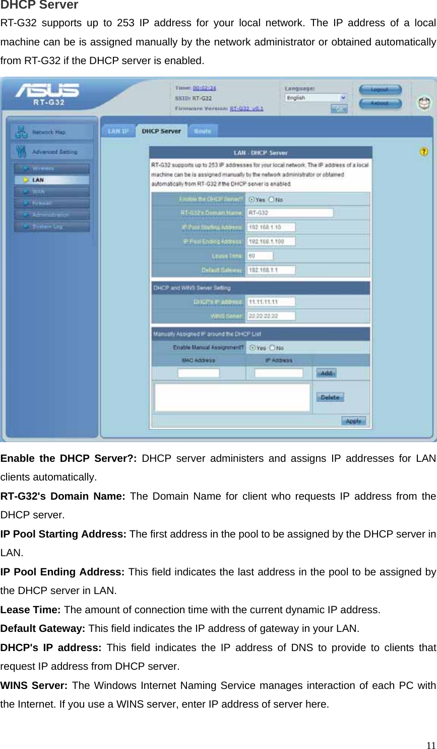
![10Time of Day to Enable Radio: This field defines the time interval that wireless function is enabled. Data Rate (Mbps): This field allows you to select the transmission rate. [Auto] is recommended to maximize performance. Fragmentation Threshold: Fragmentation Threshold sets the frame size of incoming messages (ranging from 256 to 2346 bytes) used as fragmentation boundary. If the frame size is too big, the heavy interference affects transmission reliability. If the frame size is too small, it decreases transmission efficiency. RTS Threshold: Lower the signal RTS (Request To Send) to promote the transmission efficiency in condition of noisy environment or too many clients. DTIM Interval: DTIM (Delivery Traffic Indication Message) is included in Beacon packet. The DTIM Interval (1-255) means the period of time to wake up wireless clients from Sleep Mode. The default value is 1. Beacon Interval: Beacon Interval means the period of time between one beacon and the next one. The default value is 100 (the unit is millisecond, or 1/1000 second). Lower the Beacon Interval to improve transmission performance in unstable environment or for roaming clients, but it will be power consuming. LAN Configure LAN, DHCP, and Route settings. LAN IP Configure the LAN IP of RT-G32. The DHCP Server dynamically changes the IP pool when you change the LAN IP. IP Address: The LAN IP address of RT-G32. The Default value is 192.168.1.1. Subnet Mask: The LAN subnet mask of RT-G32. The Default value is 255.255.255.0](https://usermanual.wiki/ASUSTeK-Computer/RTG32/User-Guide-1028304-Page-11.png)
![20 Enable LAN to WAN Filter?: Select [Yes] to enable filter that specify IP or port for control incoming and outgoing packets. Date to Enable LAN to WAN Filter: This field defines the dates that LAN to WAN filter will be enabled. Time of Day to Enable LAN to WAN Filter: This field defines the time interval that LAN to WAN filter will be enabled. Packets not specified will be: This field defines those LAN to WAN packets which are not specified in IP Filter Table will be accepted or dropped. Filtered ICMP packet types: This field defines a list of LAN to WAN ICMP packets type that will be filtered. For example, if you would like to filter Echo (type 8) and Echo Reply (type 0) ICMP packets, you need to enter a string with numbers separated by blank, such as, 0 5. Well-Known Applications: User Defined, WWW, Telnet, FTP Administration Configure the system and upgrade the firmware of RT-G32.](https://usermanual.wiki/ASUSTeK-Computer/RTG32/User-Guide-1028304-Page-21.png)
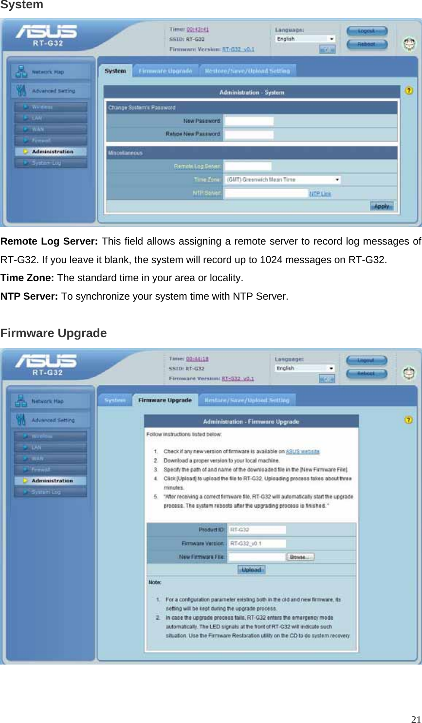
![22Follow instructions listed below: 1. Check if any new version of firmware is available on ASUS website. 2. Download a proper version to your local machine. 3. Specify the path of and name of the downloaded file in the [New Firmware File]. 4. Click [Upload] to upload the file to RT-G32. Uploading process takes about three minutes. 5. "After receiving a correct firmware file, RT-G32 will automatically start the upgrade process. The system reboots after the upgrading process is finished. Note: 1. For a configuration parameter existing both in the old and new firmware, its setting will be kept during the upgrade process. 2. In case the upgrade process fails, RT-G32 enters the emergency mode automatically. The LED signals at the front of RT-G32 will indicate such situation. Use the Firmware Restoration utility on the CD to do system recovery Restore/Save/Upload Setting This function allows you to save current settings of RT-G32 to a file, or load settings from a file. Factory default: Click [Factory default] to restore the router to its factory default settings and delete all the current settings. Wait for a while until the router reboots. Save settings: Click the [Save] button to save current setting of RT-G32 into a file. (Note: While you save current settings to a file, it will be saved to flash as well.) Restore settings: Specify the path and name of setting file. Then click [Upload] to write the file to RT-G32. Please wait 30 seconds until RT-G32 reboots.](https://usermanual.wiki/ASUSTeK-Computer/RTG32/User-Guide-1028304-Page-23.png)