ASUSTeK Computer S1000RF Notebook P.C. User Manual
ASUSTeK Computer Inc Notebook P.C. Users Manual
UserManual.wiki
>
ASUSTeK Computer
>
S1000RF User Manual
Users Manual
Navigation menu
Upload a User Manual
Namespaces
Wiki Guide
HTML
PDF
Info
Views
User Manual
Discussion / Help
Navigation
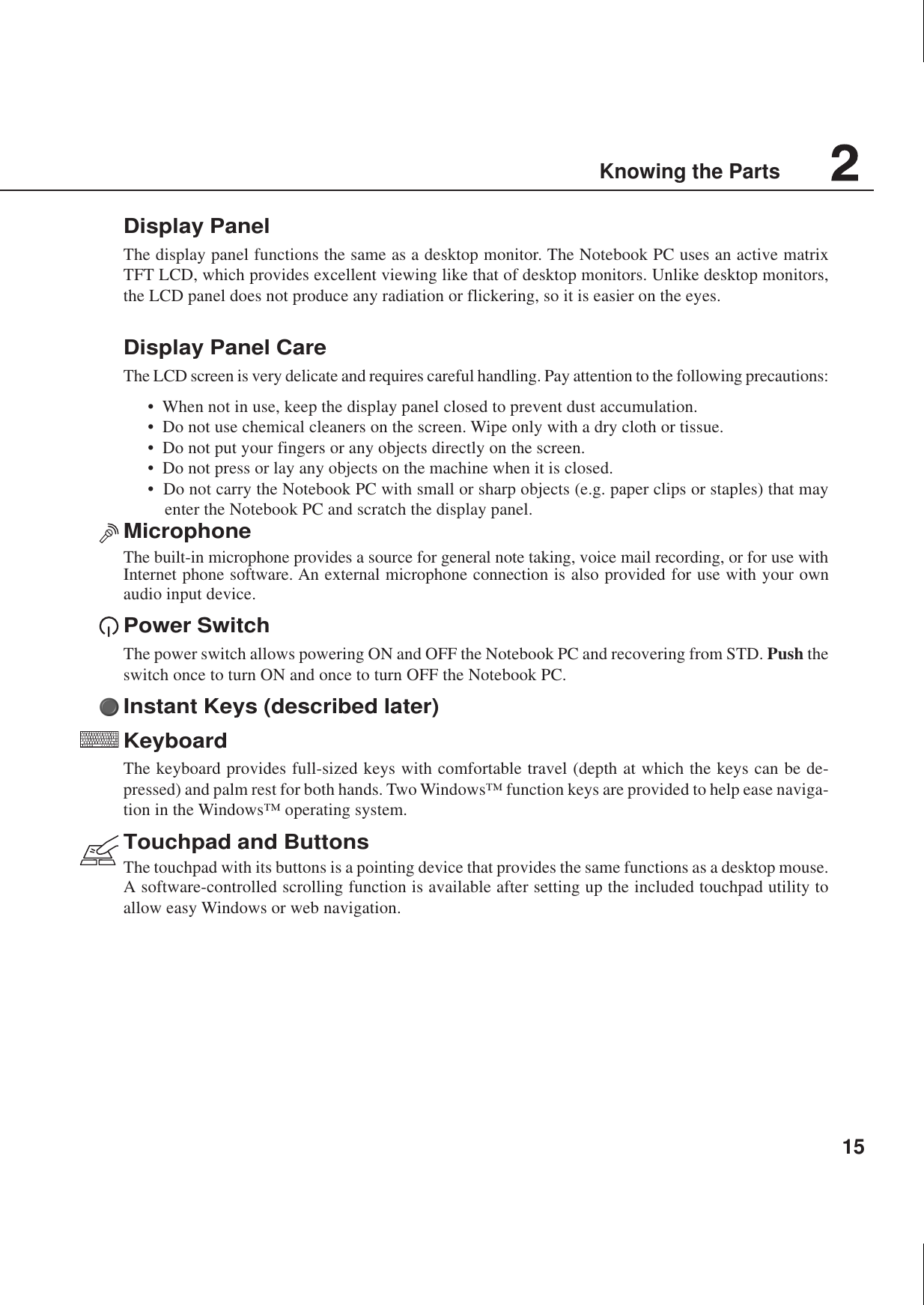
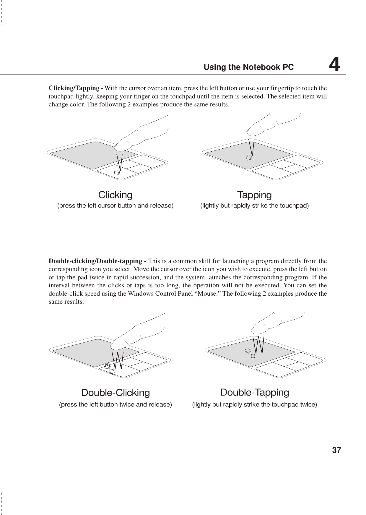
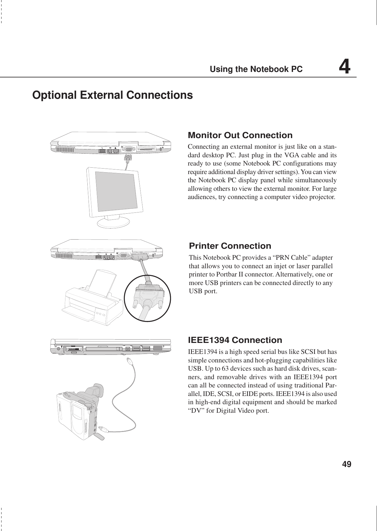
![12About This User’s ManualYou are reading the Notebook PC User’s Manual. This User’s Manual provides information on thevarious components in the Notebook PC and how to use them. The following are major sections of thisUser’s Manuals:1. Introducing the Notebook PCIntroduces you to the Notebook PC and this User’s Manual.2. Knowing the PartsGives you information on the Notebook PC’s components.3. Getting StartedGives you information on getting started with the Notebook PC.4. Using the Notebook PCGives you information on using the Notebook PC’s components.5. Configuring the BIOSGives you information on configuring the BIOS software.6. AppendixIntroduces you to optional accessories and gives additional information.Notes For This ManualThis User’s Manual was created using Macintosh versions of Adobe® PageMaker™ 6.52, Adobe®Photoshop™ 5.5, Adobe® Illustrator® 8.0, and Macromedia® Freehand™ 8.0.1. The body text type usedin this manual is “Times” (MAC) or “Times New Roman” (Windows™) and headings are “Helvetica”(MAC) or “Arial” (Windows™). A few notes and warnings in bold are used throughout this guide thatyou should be aware of in order to complete certain tasks safely and completely. These notes havedifferent degrees of importance as described below:Text enclosed in < > or [ ] represents a key on the keyboard; do not actually type the <> or [ ] and the enclosed letters.TIP: Tips and useful information forpower (advanced) computer users.NOTE: Tips and information to aid incompleting a task.WARNING! Information to preventdamage to components, damage todata, or personal injury.CAUTION! Information on actions thatmust be avoided to prevent damage tocomponents, damage to data, or per-sonal injury.Introducing the Notebook PC](https://usermanual.wiki/ASUSTeK-Computer/S1000RF/User-Guide-246706-Page-12.png)
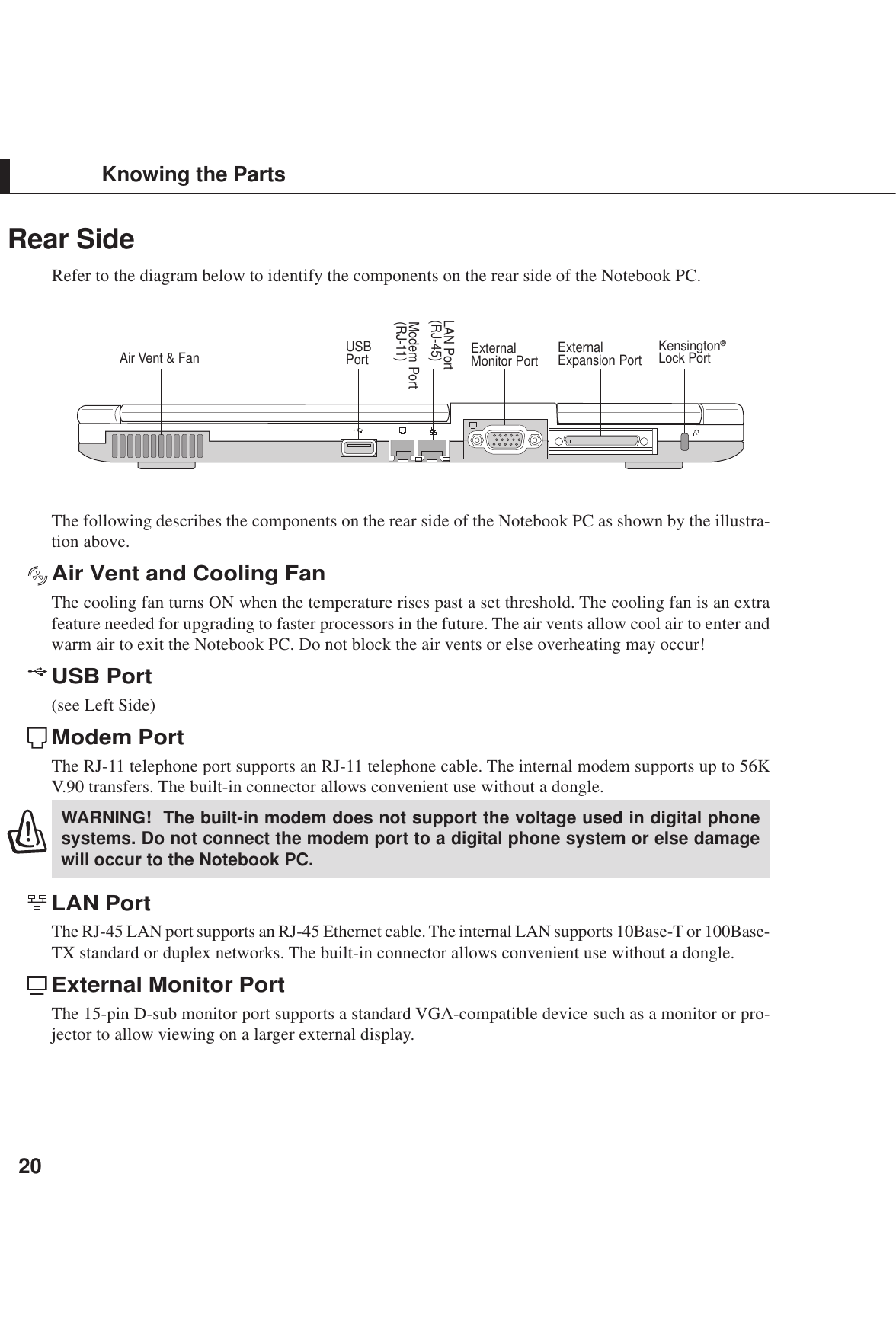
![27Getting StartedPowering ON The Notebook PCThe Notebook PC’s power-ON message appears on the screen followed by a short beep when you turn itON. If necessary, you may adjust the brightness by using the hot keys. If you need to run the BIOS Setupto set or modify the system configuration, press [F2] upon bootup to enter the BIOS Setup. If you press[Tab] during the splash screen, standard boot information such as the BIOS version can be seen. Press[ESC] and you will be presented with a boot menu with selections to boot from your available drives.WARNING! Never turn OFF or reset your Notebook PC while the hard disk or floppydisk is in use and the activity LED is flashing; doing so can result in loss or destruc-tion of your data. To protect the hard disk drive, always wait at least 5 seconds afterturning OFF your Notebook PC before turning it back ON.NOTE: Before bootup, the display panel flashes when the power is turned ON. This ispart of the Notebook PC’s test routine and is not a problem with the display.The Power-On Self Test (POST)When you turn ON the Notebook PC, it will first run through a series of software-controlled diagnostictests called the Power-On Self Test (POST). The software that controls the POST is installed as apermanent part of the Notebook PC’s architecture. The POST includes a record of the Notebook PC’shardware configuration, which is used to make a diagnostic check of the system. This record is createdby using the BIOS Setup program. If the POST discovers a difference between the record and theexisting hardware, it will display a message on the screen prompting you to correct the conflict byrunning BIOS Setup. In most cases the record should be correct when you receive the Notebook PC.When the test is finished, you may get a message reporting “No operating system found” if the harddisk was not preloaded with an operating system. This indicates that the hard disk is correctly detectedand ready for the installation of a new operating system.The S.M.A.R.T. (Self Monitoring and Reporting Technology) checks the hard disk drive during POSTand gives a warning message if the hard disk drive requires servicing. If any critical hard disk drivewarning is given during bootup, backup your data immediately and run Windows disk checking program.To run Window’s disk checking program: (1) right-click any hard disk drive icon in “My Computer”, (2)choose Properties, (3) click the Tools tab, (4) click Check Now, (5) select a hard disk drive, (6) selectThorough to also check for physical damages, and (7) click Start. Third party disk utilities such as Symantec’sNorton Disk Doctor can also perform the same functions but with greater ease and more features.WARNING! If warnings are still given during bootup after running a software diskchecking utility, you should take your Notebook PC in for servicing. Continued usemay result in data loss.](https://usermanual.wiki/ASUSTeK-Computer/S1000RF/User-Guide-246706-Page-27.png)
![28Getting StartedPower Management - Stand By and HibernatePower management settings can be found in the Windows control panel.The following shows the power options properties in Windows ME. Youcan define Stand By or Power Off for closing the display panel, pressingthe power button, or activating sleep mode. Basically Stand by and Hiber-nate saves power when your Notebook PC is not in use by turning OFFcertain components. When you resume your work, your last status (suchas a document scrolled down half way or email typed half way will reap-pear as if you never left. Power Off will close all applications and ask ifyou want to save your work if any are not saved.Stand By is the same as Suspend-to-RAM (STR). This function stores yourcurrent data and status in RAM while many components are turned OFF.Because RAM is volatile, it requires power to keep (refresh) the data.Hibernate is the same as Suspend-to-Disk (STD) and stores your currentdata and status on the hard disk drive. By doing this, RAM does not haveto be refreshed and power consumption is greatly reduced but not com-pletely eliminated because certain wake-up components like LAN andmodem needs to remain powered.Restarting or RebootingAfter making changes to your operating system, you may be prompted to restart the system. Someinstallation processes will provide a dialog box to allow restart. To restart the system manually:Click the Start button and select Shut Down | and choose Restart.In case the operating system hangs (stops, freezes, crashes), try the following in this order:1. Try a “warm boot” by pressing the [Ctrl][Alt][Del] keys simultaneously. (You may try a few times.)2. If warm booting fails to work, you can press the shut down button located in a small hole on thebottom of the Notebook PC with a pen, mechanical pencil, or paper clip. (Do not use a standardpencil because the tip may break off in the hole.)Powering OFF the Notebook PCFor operating systems equipped with ACPI (Windows ME/2000), the Notebook PC can be poweredOFF by using Start | Shut Down... | Shut down. For operating systems without proper power manage-ment (DOS, Windows NT), you must power OFF the Notebook PC by holding the power switch for 2seconds (as opposed to 1 second to power ON) after closing applications and exiting operating systems.This is necessary in order to prevent accidental power-OFFs.](https://usermanual.wiki/ASUSTeK-Computer/S1000RF/User-Guide-246706-Page-28.png)
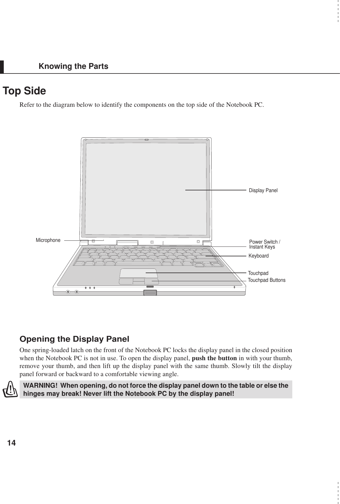
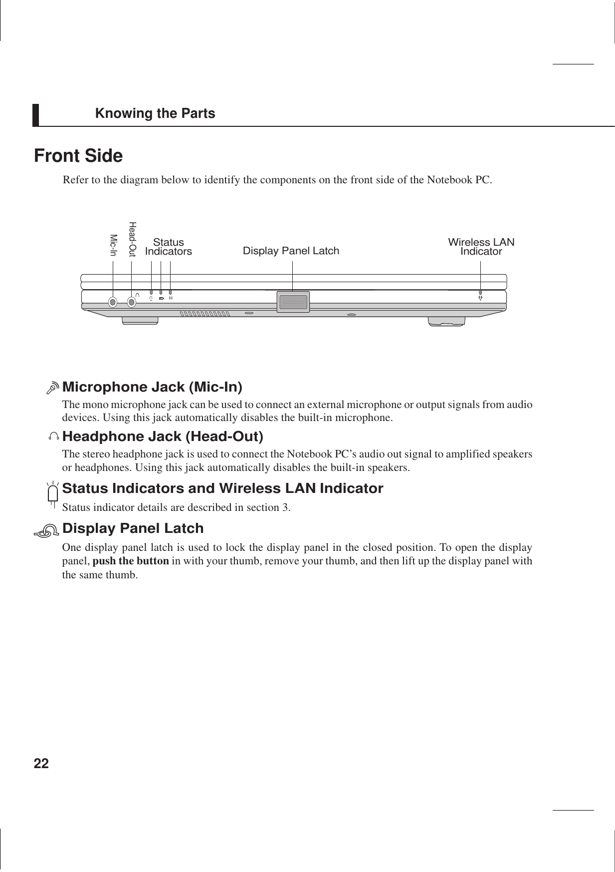
![30Getting Started1A1Above the KeyboardNOTE: A utility must be installed in order to use the “Instant Launch Keys”. See the“Driver and Utility” User’s Manual for more information.Instant Launch Keys and Status IndicatorsStatus IndicatorsActivity IndicatorIndicates that the Notebook PC is accessing one or more storage device(s) such as the hard disk oroptical storage drive. The light flashes proportional to the access time.Number LockIndicates that number lock [Num Lk] is activated when lighted. Number lock allows some of the key-board letters to act as numbers for easier numeric data input.Capital LockIndicates that capital lock [Caps Lock] is activated when lighted. Capital lock allows some of thekeyboard letters to type using capitalized letters (e.g. A, B, C). When the capital lock light is OFF, thetyped letters will be in the lower case form (e.g. a,b,c).Instant Launch KeysEmail Launch KeyPressing this button will launch your Email application. If your Notebook PC is OFF while pressingthis button, this function will first turn ON your Notebook PC.Internet Launch KeyPressing this button will launch your Internet browser application. If your Notebook PC is OFF whilepressing this button, this function will first turn ON your Notebook PC.Programmable Launch Keys (see Driver and Utility Manual)Pressing this button will launch your programmed software application. If your Notebook PC is OFFwhile pressing this button, this function will first turn ON your Notebook PC.1A](https://usermanual.wiki/ASUSTeK-Computer/S1000RF/User-Guide-246706-Page-30.png)
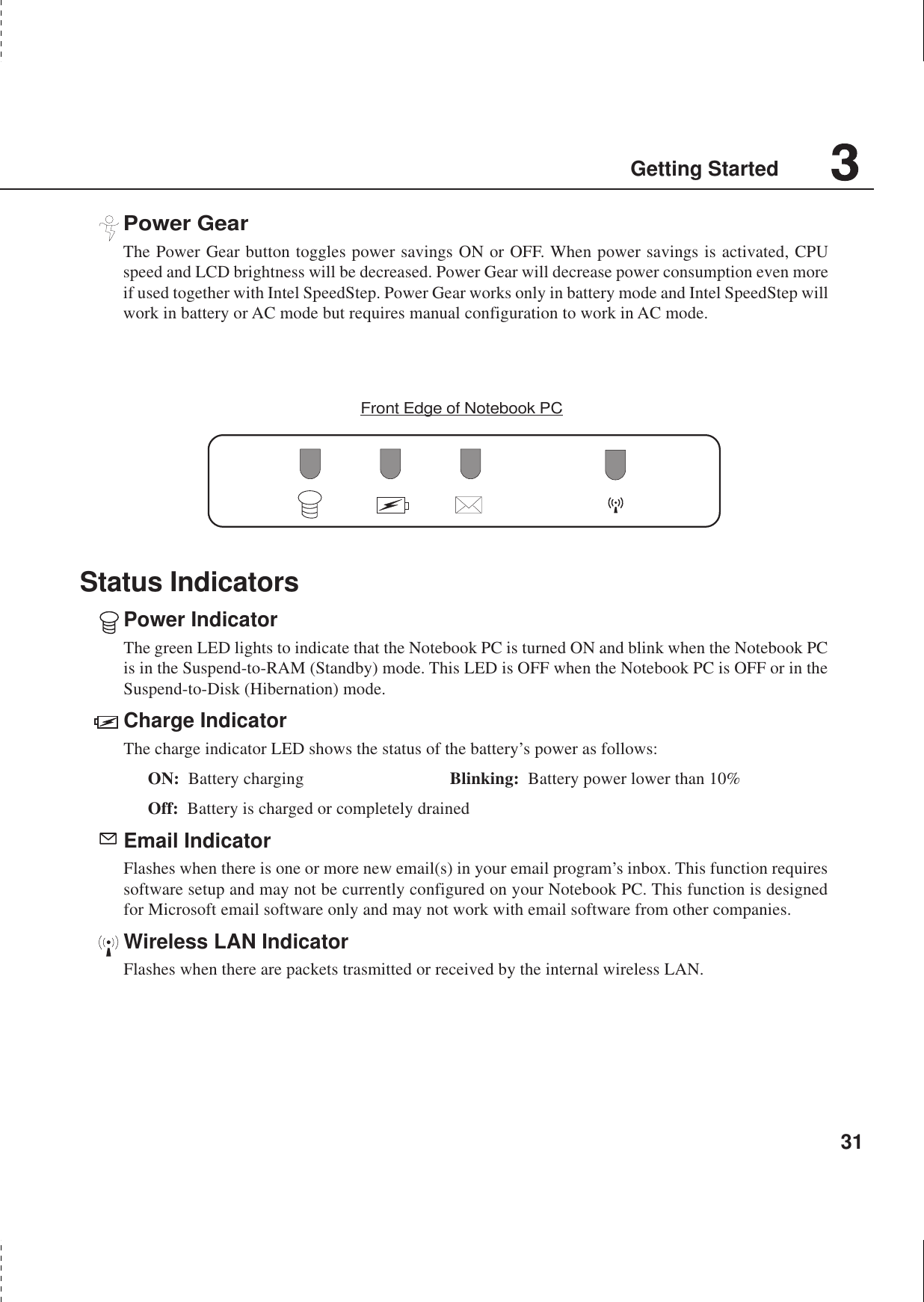
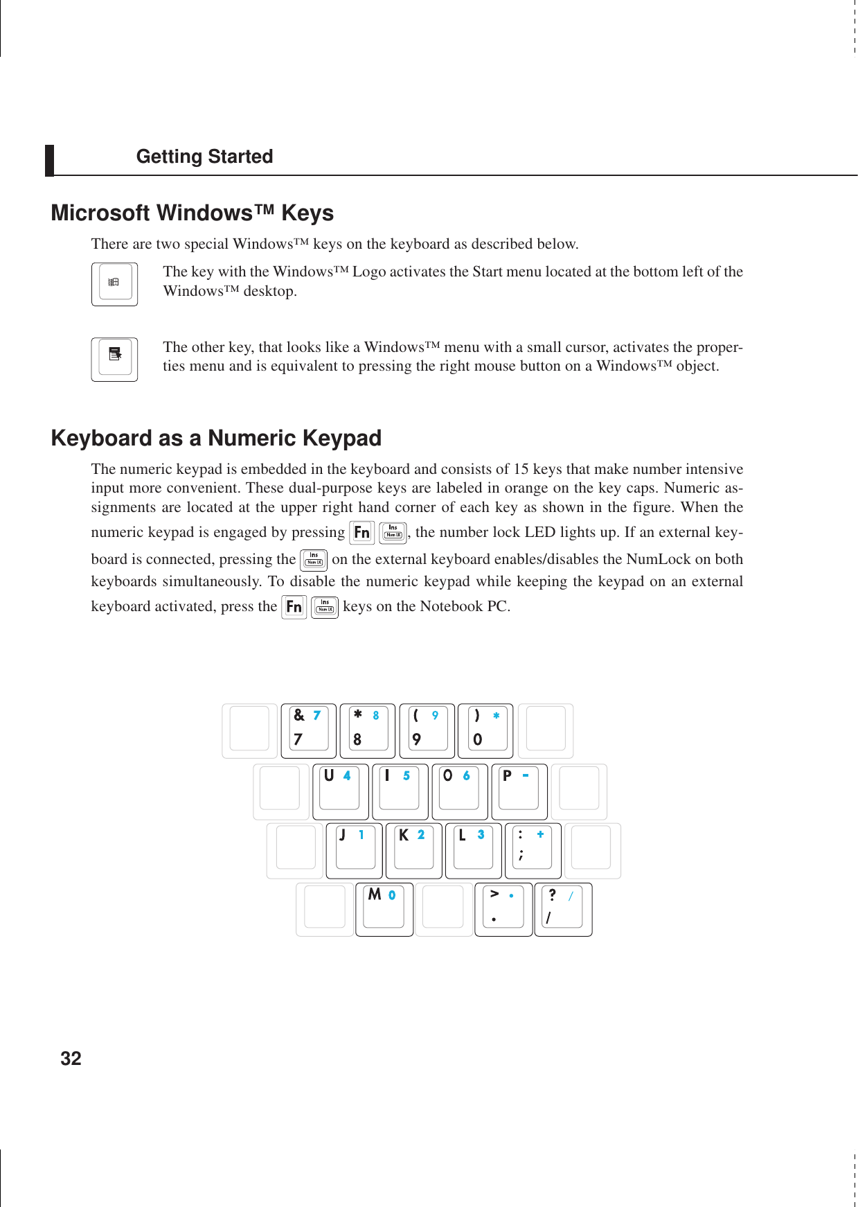
![33Getting StartedKeyboard as CursorsThe keyboard can be used as cursors while Number Lock is ON or OFF in order to increase navigationease while entering numeric data in spreadsheets or similar applications.With Number Lock OFF, press and one of the cursor keys shown below. For example [Fn][8] forup, [Fn][K] for down, [Fn][U] for left, and [Fn][O] for right.With Number Lock ON, use [Shift] and one of the cursor keys shown below. For example [Shift][8]for up, [Shift][K] for down, [Shift][U] for left, and [Shift][O] for right.NOTE: The large bold characters and symbols are printed here for your reference.They are not labeled on the keyboard as shown here.NOTE: The capital lock LED lights up when Number Lock is ON and turn OFF whenNumber Lock is OFF.](https://usermanual.wiki/ASUSTeK-Computer/S1000RF/User-Guide-246706-Page-33.png)

![60Using the Notebook PCPower Management ModesThe Notebook PC has a number of automatic or adjustable power saving features that you can use tomaximize battery life and lower Total Cost of Ownership (TCO). You can control some of these fea-tures through the Power menu in the BIOS Setup. ACPI power management settings are made throughthe operating system. The power management features are designed to save as much electricity aspossible by putting components into a low power consumption mode as often as possible but also allowfull operation on demand. These low power modes are referred to as Standby (or Suspend-to-RAM)and Hibernation mode or Suspend-to-Disk (STD). The Standby mode is a simple function provided bythe operating system. When the Notebook PC is in either one of the power saving modes, the status willbe shown by the following: Standby: Power LED Blinks and Hibernation: Power LED OFF.Full Power Mode & Maximum PerformanceThe Notebook PC operates in Full Power mode when the power management function is disabled byconfiguring Windows power management and Speedstep (see Driver & Utility manual). When theNotebook PC is operating in Full Power Mode, the Power LED remains ON. If you are conscious ofboth system performance and power consumption, select “Maximum Performance” instead of dis-abling all power management features.ACPIAdvanced Configuration and Power Management (ACPI) was developed by Intel, Microsoft, and Toshibaespecially for Windows and later to control power management and Plug and Play features. ACPI is thenew standard in power management for Notebook PCs. If installing Windows 98 using a BIOS dated12/1/1999 or later, ACPI is automatically installed.NOTE: APM was used in older operating systems like Windows NT4 and Windows 98.Because newer operating systems like Windows 2000 and Windows ME utilize ACPI,APM is no longer fully supported on this Notebook PC.Suspend ModeIn Standby and Hibernation, the CPU clock is stopped and most of the Notebook PC devices are put intheir lowest active state. The suspend mode is the lowest power state of the Notebook PC. The NotebookPC enters Suspend when the system remains idle for a specified amount of time or manually using the[Fn][F1] keys. The Power LED blinks when the Notebook PC is in STR mode. In STD mode, the Note-book PC will appear to be powered OFF. Recover from STR by pressing any keyboard button(except Fn). Recover from STD by using the power switch (just like powering ON the NotebookPC).](https://usermanual.wiki/ASUSTeK-Computer/S1000RF/User-Guide-246706-Page-60.png)
![61Using the Notebook PCThermal Power ControlThere are three power control methods for controlling the Notebook PC’s thermal state. These powercontrol cannot be configured by the user and should be known in case the Notebook PC should enterthese states. The following temperatures represent the chassis temperature (not CPU).•The fan turns ON for active cooling when the temperature reaches the safe upper limit.•The CPU decreases speed for passive cooling when the temperature exceeds the safe upper limit.•The system shut down for critical cooling when temperature exceeds the maximum safe upper limit.Power SavingsIn addition to reducing the CPU clock, this mode puts devices including the LCD backlight in theirlower active state. The Notebook PC enters Standby mode (low priority) when the system remains idlefor a specified amount of time. The timeout can be set through BIOS setup (lower priority) and Win-dows power management (higher priority). To resume system operation, press any key.Power State SummarySTATE ENTRY EVENT EXIT EVENTStand by • Stand by through Windows Start button, • Any device• Timer as set though “Power Management”• Battery low in Windows Control Panel (higher priority)STR (Standy By) • Ring indicator • Any Key(Save-to-RAM) • Sleep button [FN F1]STD (Hibernate) • Power button • Power button(Save-to-Disk) • Battery Extremely Low](https://usermanual.wiki/ASUSTeK-Computer/S1000RF/User-Guide-246706-Page-61.png)
![66Configuring the BIOSBIOS Setup ProgramThis Notebook PC supports a programmable EEPROM that stores the BIOS software and can be up-dated using the provided flash memory writer utility. This Section will guide you through the BIOSsetup program by providing clear explanations for all the options. A default configuration has alreadybeen set. If you are either installing new devices or expanding main memory, you will need to enter theBIOS Setup to reconfigure your Notebook PC.A battery backed-up CMOS RAM is used to record some basic system hardware information: clock,date, time, the error handling, and etc., even when the power is off. When the Notebook PC is turnedback on, the system is configured with the values stored in the CMOS RAM.The settings made in the BIOS Setup program intimately affect how the Notebook PC performs. It isimportant, therefore, to first understand all the Setup options, and second, to make settings appropriatefor the way you use the Notebook PC.The BIOS (Basic Input and Output System) Setup is a menu driven software utility that enables you tomake changes to the system configuration and tailor your Notebook PC to reflect installed hardware,alter performance, and setup power saving functions. BIOS setup is used if you are setting up theNotebook PC for the first time, reconfiguring your system, or prompted to “Run Setup” during bootup.This section describes how to configure your system using this utility.Even if you are not prompted to use the Setup program, at some time in the future you may want tochange the configuration of your Notebook PC. For example, you may want to enable the SecurityPassword Feature or make changes to the power management settings. It will then be necessary toreconfigure your system using the BIOS setup program so that the computer can recognize these changesand record them in the CMOS RAM of the EEPROM.The Setup program has been designed to make it as easy to use as possible. It is a menu-driven pro-gram, which means you can scroll through the various sub-menus and make your selections among thepredetermined choices.When you start up the computer, press [F2] to call up the Setup utility.NOTE: Because the BIOS software is constantly being updated, the following BIOSscreens and descriptions are for reference purposes only and may not exactly reflectyour BIOS screens.](https://usermanual.wiki/ASUSTeK-Computer/S1000RF/User-Guide-246706-Page-66.png)
![Configuring the BIOS67Updating your BIOSThis Notebook PC supports an easy-to-use BIOS update software called “WINFLASH” which is in-stalled through the provided support CD. If you need help installing or using “WINFLASH”, refer tothe “Driver & Utility Manual”.BIOS Menu BarThe top of the screen has a menu bar with the following selections:MAIN Use this menu to make changes to the basic system configuration.ADVANCED Use this menu to enable and make changes to the advanced featuresSECURITY Use this menu to set a password to control bootup and control accessto the BIOS setup menu.POWER Use this menu to configure and enable Power Management features.BOOT Use this menu to configure the default system device used to locateand load the Operating System.EXIT Use this menu to exit the current menu or specify how to exit the Setup program.To access the menu bar items, press the right or left arrow key on the keyboard until the desired item ishighlighted.BIOS Legend BarAt the bottom of the Setup screen you will notice a legend bar. The keys in the legend bar allow you tonavigate through the various setup menus. The following table lists the keys found in the legend bar andthose that are not with their corresponding alternates and functions.Navigation Key(s) Function Description[F1] or [Alt H] Displays the General Help screen from anywhere in the BIOS Setup[Esc] or [Alt X] Jumps to the Exit menu or returns to the main menu from a sub-menu← ← ← ← ← or →→→→→ (keypad arrow) Selects the menu item to the left or right↑↑↑↑↑ or ↓↓↓↓↓ (keypad arrows) Moves the highlight up or down between fields– (minus) or [F5] Scrolls backward through the values for the highlighted field+ (plus) or [F6] or space Scrolls forward through the values for the highlighted field[Enter] Brings up a selection menu for the highlighted field[Home] or [PgUp] Moves the cursor to the first field[End] or [PgDn] Moves the cursor to the last field[F9] Resets the current screen to its Setup Defaults[F10] Saves changes and exits Setup](https://usermanual.wiki/ASUSTeK-Computer/S1000RF/User-Guide-246706-Page-67.png)
![68Configuring the BIOSGeneral HelpIn addition to the Item Specific Help window, the BIOS setup program also provides a General Helpscreen. This screen can be called up from any menu by simply pressing [F1] or the [Alt] + [H] combi-nation. The General Help screen lists the legend keys with their corresponding alternates and functions.Scroll BarWhen a scroll bar appears to the right of a help window, it indicates that there is more information to bedisplayed that will not fit in the window. Use [PgUp] and [PgDn] or the up and down arrow keys toscroll through the entire help document. Press [Home] to display the first page, press [End] to go to thelast page. To exit the help window, press [Enter] or [Esc].Sub-MenuNote that a right pointer symbol (as shown in the left view) appears to the left of certainfields. This pointer indicates that a sub-menu can be launched from this field. A sub-menu contains additional options for a field parameter. To call up a sub-menu, simplymove the highlight to the field and press [Enter]. The sub-menu will then immediatelyappear. Use the legend keys to enter values and move from field to field within a sub-menu just as you would within a menu. Use the [Esc] key to return to the main menu.Take some time to familiarize yourself with each of the legend keys and their corresponding functions.Practice navigating through the various menus and sub-menus. While moving around through the Setupprogram, note that explanations appear in the Item Specific Help window located to the right of eachmenu. This window displays the help text for the currently highlighted field.Resetting Your BIOSIf you ever hear “resetting yourBIOS”, it entails pressing [F2] onbootup to enter BIOS setup and thenselecting Load Setup Defaults onthe “Exit” menu.Item Specific HelpExit Saving ChangesExit Discarding ChangesLoad Setup DefaultsDiscard ChangesSave ChangesExit setup utility andsave your changes toCMOS.](https://usermanual.wiki/ASUSTeK-Computer/S1000RF/User-Guide-246706-Page-68.png)
![Configuring the BIOS69NOTE: In the following BIOS item descriptions, the item headings in square bracketsrepresent the default settings for those fields.System TimeSets your system to the time that you specify (usually the current time). The format is hour, minute,second. Insert the appropriate information. Use the [Tab] or [Shift Tab] keys to move between the hour,minute, and second fields.System DateSets your system to the date that you specify (usually the current date). The format is month, day, year.Type in the appropriate information. Use the [Tab] or [Shift Tab] keys to move between the month, day,and year fields.>Secondary Master (described later)>Secondary Slave (described later)Item Specific HelpSystem Time [17:15:00]System Date [11/19/2001]Primary Master [IC25N030ATDA04-0]Primary Slave [Auto]Secondary Master [Auto]Secondary Slave [Auto]Video Display Device [LCD & CRT]Installed Memory 128 MB<Enter> to select field;<+>,<-> to change value.Main MenuWhen the Setup program is accessed, the main menu screen appears as shown:](https://usermanual.wiki/ASUSTeK-Computer/S1000RF/User-Guide-246706-Page-69.png)
![70Configuring the BIOSVideo Display Device [LCD & CRT]This field allows you to select and enable video display devices, such as an LCD panel, an externalCRT/LCD monitor, or both. The configuration options are: [LCD & CRT] [LCD] [CRT]Installed Memory [128 MB] (display field)This field displays the amount of extended memory as detected by the system. Unfortunately, this willnot tell you how much is onboard and how much is added to the SO-DIMM socket. You must visuallyinspect the SO-DIMM socket if you are considering expanding your memory. You cannot make changesto this field. This is a display only field.](https://usermanual.wiki/ASUSTeK-Computer/S1000RF/User-Guide-246706-Page-70.png)
![Configuring the BIOS71Type: [Auto]Select Auto to automatically detect an IDE type drive. This option only works with standard built-inIDE drives. If automatic detection is successful, the correct values will be filled in for the remainingfields on this sub-menu.To configure a drive manually, select User Type HDD. Manually enter the number of cylinders, headsand sectors per track for your drive. Refer to your drive documentation or look on the drive for thisinformation. If no drive is installed or if you are removing a drive and not replacing it, select None. Setthe type to CD-ROM to support a CD-ROM or DVD-ROM drive.Translation MethodTranslation method allows you to select the sector addressing method. Match Partition Table is rec-ommended if there is already an OS on the hard drive you are installing to this Notebook PC. Manualallows you to specify cylinders, heads, and sectors. [LBA] When Logical Block Addressing is enabled,28-bit addressing of the hard drive is used without regard for cylinders, heads, or sectors. Note thatLogical Block Access may decrease the access speed of the hard disk. However, LBA Mode is neces-sary for drives with greater than 504MB in storage capacity. The configuration options are: [LBA][LARGE] [Normal] [Match Partition Table] [Manual]Item Specific Help Primary Master [IC25N030ATDA04-0]<Enter> to select thetype of the IDE drive.[User Type HDD] allowsyou to set each entry onyour own.WARNING: Ultra DMA mode3/4/5 can be enabledonly when BIOS detectsshielded 80-pin cable.Type: [Auto]Cylinders [ 1024]Heads [255]Sectors [63]CHS Capacity 8422MBMaximum LBA Capacity 30005MBMulti-Sector Transfers [Maximum]SMART Monitoring [Disabled]PIO Mode [4]Ultra DMA Mode [5]NOTE: Before attempting to configure a hard disk drive, make sure you have the con-figuration information supplied by the manufacturer of the drive. Incorrect settingsmay cause your system to not recognize the installed hard disk. To allow the BIOS todetect the drive type automatically, select [AUTO].Primary Master (sub-menu)This field is used to configure the primary IDE drive installed in the system. To configure a hard diskdrive, select this sub-menu from the Main menu and press the Enter key to enter this sub-menu.](https://usermanual.wiki/ASUSTeK-Computer/S1000RF/User-Guide-246706-Page-71.png)
![72Configuring the BIOSCylinders [ ]This field configures the number of cylinders. Refer to your drive documentation to determine the correct valueto enter into this field. NOTE: To make changes to this field, the Type field must be set to User Type HDD and“Translation Method” must be set to Manual.Heads [ ]This field configures the number of read/write heads. Refer to your drive documentation to determine the correctvalue to enter into this field. NOTE: To make changes to this field, the Type field must be set to User TypeHDD and “Translation Method” must be set to Manual.Sectors [ ]This field configures the number of sectors per track. Refer to your drive documentation to determinethe correct value to enter into this field. NOTE: To make changes to this field, the Type field must be set toUser Type HDD and “Translation Method” must be set to Manual.CHS Capacity [ ]This field shows the drive’s CHS capacity calculated automatically by the BIOS from the drive infor-mation you entered.Maximum LBA Capacity [ ]This field shows the drive’s maximum capacity calculated automatically by the BIOS from the driveinformation you entered.Multi-Sector Transfers [Maximum]This option automatically sets the number of sectors per block to the highest number supported by thedrive. This field can also be configured manually. Note that when this field is automatically configured,the set value may not always be the fastest value for the drive. Refer to the documentation that camewith your hard drive to determine the optimal value and set it manually. NOTE: To make changes tothis field, the Type field must be set to User Type HDD. The configuration options are: [Disabled] [2Sectors] [4 Sectors] [8 Sectors] [16 Sectors] [32 Sectors] [Maximum]SMART Monitoring [Disabled]Self-Monitoring Analysis and Reporting Technology (S.M.A.R.T.) is an interface between a computer'sBIOS and hard disk. It is a feature of the Enhanced Integrated Drive Electronics (EIDE) technologythat controls access to the hard drive. If S.M.A.R.T is enabled, the BIOS can receive analytical infor-mation from the hard drive and determine whether to send the user a warning message about possiblefuture failure of the hard drive. Ideally, this should allow you to take proactive actions to preventimpending disk crashes.PIO Mode [ ]When enabled, this option speeds up communication between the system and the IDE controller by usingenhanced I/O transfer modes (PIO Modes). NOTE: To make changes to this field, the Type field must beset to User Type HDD. The configuration options are: [0] [1] [2] [3] [4]](https://usermanual.wiki/ASUSTeK-Computer/S1000RF/User-Guide-246706-Page-72.png)
![Configuring the BIOS73Secondary Master (sub-menus)This field is used to configure the secondary IDE drive installed in the system. To configure a hard diskdrive, select this sub-menu from the Main menu and press the Enter key to enter this sub-menu.The fields and options on this sub-menu are the same as the previous menu described earlier. Leave onthe default setting of Auto.NOTE: The Secondary drive displayed here is for example only. The actual display willbe dependent on the drive you have installed in your Notebook PC.After using the legend keys to make your selections in this sub-menu, press the [Esc]key to return to the Main menu.Item Specific HelpPrimary Slave [Auto]Type [Auto] <Enter> to select thetype of the IDE drive.[User Type HDD] allowsyou to set each entry onyour own.Ultra DMA Mode [ ]This field auto detects Ultra DMA capability (for improved transfer speeds and data integrity) for compatibleIDE (Integrated Disk Electronics) devices. Set to Disable to suppress Ultra DMA capability. NOTE: Tomake changes to this field, the Type field must be set to User Type HDD. The configuration options are: [0][1] [2] [3] [4] [5] [Disabled]. The following is for your reference:Mode 2 = ATA/33 = 33MB/s; Mode 4 = ATA/66 = 66MB/s; Mode 6 = ATA/100 = 100MB/sNOTE: After using the legend keys to make your selections on this sub-menu, press the[Esc] key to exit back to the Main menu. When the Main menu appears, you will noticethat the drive size appears in the field for the hard disk drive that you just configured.](https://usermanual.wiki/ASUSTeK-Computer/S1000RF/User-Guide-246706-Page-73.png)
![74Configuring the BIOS>I/O Device Configuration (described on next page)Pressing [Enter] when this field is highlighted calls up a sub-menu for configuring the Notebook PC’sserial and parallel ports.Internal Pointing Device [Enabled]This allows you to turn ON or OFF the Notebook PC’s built-in touchpad. Some external pointingdevices have extra functions that may not function without turning OFF the Notebook PC’s touchpad.The configuration options are: [Enabled] [Disabled]Processor Serial Number [Enabled] (only shows on PIII CPU)The Processor Serial Number is a unique number that is added to every Pentium III processor to helpverify the identity of the user across the Internet. Set this field to [Enabled] when you need increasedsecurity for doing business online or e-commerce. Otherwise, set to [Disabled] for greater anonymitywhen surfing the Internet. [Disabled] prohibits any software from reading the unique identifier of theinstalled processor. The configuration options are: [Disabled] [Enabled]Quick Power On Self Test [Enabled]This field speeds up the Power-On-Self Test (POST) routine by skipping certain redundant tests. Con-figuration options are: [Disabled] [Enabled]Advanced MenuSelecting Advanced from the main menu bar display the Advanced menu as shown below.Item Specific HelpI/O Device ConfigurationInternal Pointing Device [Enabled]Quick Power On Self Test [Enabled] <Enter> to go to thesub-menu.](https://usermanual.wiki/ASUSTeK-Computer/S1000RF/User-Guide-246706-Page-74.png)
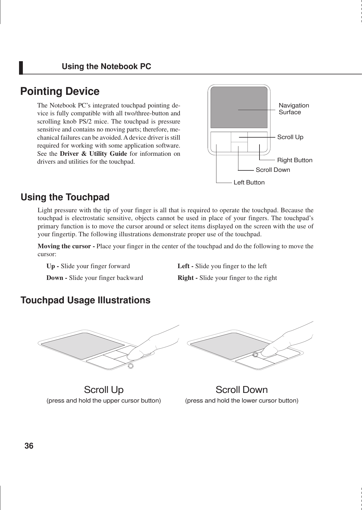
![Configuring the BIOS75I/O Device Configuration (sub-menu)Item Specific HelpI/O Device ConfigurationIR Port [2F8H/IRQ3] Mode [FIR] DMA Channel [1]Parallel Port: [378H/IRQ7] Mode: [ECP+EPP] ECP DMA Select: [3]<Enter> to select theI/O Address & IRQ forInfrared.NOTE: The presence of sub-items in this menu is dependent on certain relevant settings.WARNING! Changing the default address and IRQ settings for Serial Port or ParallelPort can cause conflicts with other system devices or installed peripherals.IR Port: [2F8H/IRQ3]This field allows you to configure the Notebook PC’s serial IR port. To enable this port, select anaddress that does not conflict with another port. A conflict will be noted by red asterisks next to thisitem and the item in conflict with. The configuration options are:[3F8H/IRQ4] [2F8H/IRQ3] [3E8H/IRQ4] [2E8H/IRQ3] [Disabled]Mode: [FIR]The Mode field allows you to select either Standard Infrared (SIR) or Fast Infrared (FIR) commu-nication mode. The configuration options are: [SIR] [FIR]DMA Channel: [1]The DMA Channel field allows you to configure the Parallel port DMA Channel for the selectedECP mode. The configuration options are: [1] [3]](https://usermanual.wiki/ASUSTeK-Computer/S1000RF/User-Guide-246706-Page-75.png)
![76Configuring the BIOSParallel Port: [378H/IRQ7]This field allows you to configure the Notebook PC parallel port. The configuration options are: [Dis-abled] [378H/IRQ7] [278H/IRQ5]Mode: [ECP+EPP]The Mode field allows you to configure the Notebook PC parallel port transmission mode. Theconfiguration options are: [Normal] [EPP] [ECP] [ECP+EPP]EPP Mode: When the EPP mode is selected, the standard and bidirectional modes are also avail-able. The EPP operates on a two phase cycle. First, the host selects the register within a device forsubsequent operations. Second, the host performs a series of read and/or write byte operations tothe selected register. There are four operations supported by EPP: Address Write, Data Write,Address Read, and Data Read. All operations are performed asynchronously.ECP Mode: The port is both software and hardware compatible with existing parallel ports so thatit may be used as a standard printer mode if ECP is not required. ECP mode provides an automatichigh burst-bandwidth channel that supports DMA for ECP in both the forward (host to peripheral)and reverse (peripheral to host) direction.DMA Channel: [3]The DMA Channel field allows you to configure the Parallel port DMA Channel for the selectedECP mode. The configuration options are: [1] [3]NOTE: After using the legend keys to make your selections for the I/O Device Con-figuration sub-menu, press the [Esc] key to exit back to the Advanced menu.](https://usermanual.wiki/ASUSTeK-Computer/S1000RF/User-Guide-246706-Page-76.png)
![Configuring the BIOS77Security MenuThe Notebook PC’s advanced system of security allows you to set a password to prevent unauthorizedaccess to system resources, data, and the BIOS Setup Program. This Section covers each parameter ofthe Security Setup. Selecting Security from the menu bar displays the following menu:Item Specific HelpSupervisor passwordcontrols full access.<Enter> to changepassword ; <Enter> againto disable password.System Password [Enter]Password on boot [Disabled]Hard disk Password [Enter]The BIOS Setup program allows you to specify passwords in the Security menu. The passwords controlaccess to the BIOS and certain Security menu options during system startup. The passwords are notcase sensitive. In other words, it makes no difference whether you enter a password using upper orlowercase letters.The BIOS Setup program allows you to specify two separate passwords: a Supervisor password and aUser password. When disabled, anyone may access all BIOS Setup program functions. When enabled,the Supervisor password is required for entering the BIOS Setup program and having full access to allSecurity menu options.](https://usermanual.wiki/ASUSTeK-Computer/S1000RF/User-Guide-246706-Page-77.png)
![78Configuring the BIOSSystem Password [Enter]The system password protects the BIOS settings. When “Enabled”, you will be prompted for a pass-word after you press [F2] to enter BIOS setup.To Enable: Select “Enter” and press [Enter], type a password and press [Enter], type the same pass-word again and press [Enter] to confirm. (You can type up to eight alphanumeric characters. Symbolsand other keys are ignored.)To Disable: Select “Set” and press [Enter] without entering a password.Password on boot [Disabled]Password on boot requires the “System Password” to be “Enabled”. When “Enabled”, you will beprompted for a password during bootup after the chance to enter BIOS setup. (To enter BIOS setup,[F2] must be pressed before the password prompt.)To Enable: Select “Disabled” and press [Enter], use the up/down cursor to select “Enable”To Disable: Select “Enabled” and press [Enter], use the up/down cursor to select “Disable”NOTE: If “Password on Boot” and “Hard Disk Password” are both “Enabled”, the “Hard Disk Pass-word” will be required first.Hard Disk Password [Enter]A hard disk password places a protection on the hard disk drive so that a password is necessary in orderto access the hard disk drive. When “Enabled”, the hard disk drive will be protected as follows:• The protected hard disk drive will prompt for a password when accessed on the Notebook PC.• The protected hard disk drive cannot be used as a master or slave drive on another computer.• The protected hard disk drive cannot be formatted.To Enable: Select “Enter” and press [Enter], type a password and press [Enter], type the same pass-word again and press [Enter] to confirm. (You can type up to eight alphanumeric characters. Symbolsand other keys are ignored.)To Disable: Select “Set” and press [Enter], enter the password and press [Enter].NOTE: If “Password on Boot” and “Hard Disk Password” are both “Enabled”, the “Hard Disk Pass-word” will be required first.](https://usermanual.wiki/ASUSTeK-Computer/S1000RF/User-Guide-246706-Page-78.png)
![Configuring the BIOS79Power MenuThe power management settings are controlled by the operating system. This menu only has one func-tion as follows:Item Specific HelpLCD auto power saving [Enabled]Start Battery Refreshing <Enter> to select thePower Saving Mode. Youcan select ‘User Define”to go to the SuspendMode entry below.LCD Auto Power Saving [Enabled]Enabling this item will decrease the LCD brightness when the AC power is not connected in order toconserve battery power. The configuration options are: [Disabled] [Enabled].Start Battery RefreshingThis function will start a software program to remove memory effects in the battery and recalibrate thebattery gauge. Even though this Notebook PC uses a Lithium-Ion battery which is not prone to memoryeffects, memory effects will still occur at the end of the battery’s life cycle. Remember that all recharge-able batteries only have a definite number of charge and discharge cycles depending on environmentand quality of the battery pack. Follow the instructions shown on the screen. You will be required toremove the AC power adapter before using this function.](https://usermanual.wiki/ASUSTeK-Computer/S1000RF/User-Guide-246706-Page-79.png)
![80Configuring the BIOSBoot MenuThe Boot menu allows the user to specify the order in which the Notebook PC is to check for a deviceto boot the system. To make changes, select Boot from the menu bar and the following screen appears:Item Specific Help1. Removable Device [USB FDD]2. IDE Hard Drive [IC25N030ATDA04-0]3. ATAPI CD-ROM [None]4. Other Boot Device [INT18 Device (Network)]Onboard LAN Boot ROM [Disabled]Boot Sequence:<Enter> to select thedevice.To select the bootsequence, use the up ordown arrow. Press <+> tomove the device up thelist, or <-> to move itdown the list.Boot Sequence1. Removable Device2. IDE Hard Drive3. ATAPI CD-ROM4. Other Boot DeviceOnboard LAN Boot ROM - Select Network drive bootup capability as [Disabled] or [Enabled].The Boot menu allows you to select among the three possible boot devices listed using the up and downarrow keys . By using the [+] or [Shift =] keys, you can promote devices and by using the [-] key, youcan demote devices. Press [Enter] to select the specific device or Disabled to never boot from thatdevice.Promotion or demotion of devices alters the priority which the system uses to search for a boot deviceon system power up. The following are explanations of the devices listed in the boot sequence:Removable Device refer to the floppy disk used in the internal or USB floppy disk drive.IDE Hard Drive refers to the internal built-in hard disk drive.ATAPI CD-ROM refers to either the built-in CD-ROM drive or DVD-ROM drive.Other Boot Device currently refers to booting from a network drive.NOTE: To boot from LAN, set this item to the top and Enable “Onboard LAN Boot ROM”.](https://usermanual.wiki/ASUSTeK-Computer/S1000RF/User-Guide-246706-Page-80.png)
![Configuring the BIOS81Exit MenuOnce you have made all of your selections from the various menus in the Setup program, you shouldsave your changes and exit Setup. Select Exit from the menu bar to display the following menu:NOTE: Pressing the [Esc] key does not exit this menu. You must select one of theoptions from this menu or a menu bar item to exit this menu.Exit Saving ChangesOnce you are finished making your selections, choose this option from the Exit menu to ensure thevalues you selected are saved to the CMOS RAM. The CMOS RAM is sustained by an onboard backupbattery and stays on even when the Notebook PC is turned off. Once this option is selected, a confirma-tion is asked. Select Yes to save changes and exit.Exit Discarding ChangesThis option should only be used if you do not want to save the changes you have made to the Setupprogram. If you have made changes to the fields other than system date, system time, and password, thesystem will ask for confirmation before exiting.Item Specific HelpExit Saving ChangesExit Discarding ChangesLoad Setup DefaultsDiscard ChangesSave ChangesExit setup utility andsave your changes toCMOS.](https://usermanual.wiki/ASUSTeK-Computer/S1000RF/User-Guide-246706-Page-81.png)
![Configuring the BIOSLoad Setup DefaultsThis option allows you to load the default values for each of the parameters on the Setup menus. Whenthis option is selected or if [F9] is pressed, a confirmation is requested. Select Yes to load default valuesprogrammed into the BIOS file (the default values may change from one BIOS version to another). Youcan now select Exit Saving Changes or make other changes before saving the values to the EEPROM.Discard ChangesThis option allows you to discard the selections you made and restore the values you previously saved.After selecting this option, all selections are updated and a confirmation is requested. Select Yes todiscard any changes and load the previously saved values.Save ChangesThis option saves your selections without exiting the Setup program. You can then return to othermenus and make changes. After selecting this option, all selections are saved and a confirmation isrequested. Select Yes to save any changes to the EEPROM.](https://usermanual.wiki/ASUSTeK-Computer/S1000RF/User-Guide-246706-Page-82.png)