ASUSTeK Computer WL127 Wireless Lan Card User Manual WL127 p65
ASUSTeK Computer Inc Wireless Lan Card WL127 p65
User Manual

®
WL-127
Wireless Fidelity Card
Installation Guide
First Edition
June 2003

2 ASUS WL-127 Card
No part of this documentation, including the products and software described in it, may be reproduced, transmitted, transcribed,
stored in a retrieval system, or translated into any language in any form or by any means, except documentation kept by the
purchaser for backup purposes, without the express written permission of ASUSTeK COMPUTER INC. (“ASUS”).
ASUS PROVIDES THIS DOCUMENTATION “AS IS” WITHOUT WARRANTY OF ANY KIND, EITHER EXPRESS OR IMPLIED,
INCLUDING BUT NOT LIMITED TO THE IMPLIED WARRANTIES OR CONDITIONS OF MERCHANTABILITY OR FITNESS
FOR A PARTICULAR PURPOSE. IN NO EVENT SHALL ASUS, ITS DIRECTORS, OFFICERS, EMPLOYEES OR AGENTS BE
LIABLE FOR ANY INDIRECT, SPECIAL, INCIDENTAL, OR CONSEQUENTIAL DAMAGES (INCLUDING DAMAGES FOR
LOSS OF PROFITS, LOSS OF BUSINESS, LOSS OF USE OR DATA, INTERRUPTION OF BUSINESS AND THE LIKE), EVEN
IF ASUS HAS BEEN ADVISED OF THE POSSIBILITY OF SUCH DAMAGES ARISING FROM ANY DEFECT OR ERROR IN
THIS DOCUMENTATION OR PRODUCT.
Product warranty or service will not be extended if: (1) the product is repaired, modified or altered, unless such repair, modification
of alteration is authorized in writing by ASUS; or (2) the serial number of the product is defaced or missing.
Products and corporate names appearing in this documentation may or may not be registered trademarks or copyrights of their
respective companies, and are used only for identification or explanation and to the owners’ benefit, without intent to infringe.
For documentation updates, visit the ASUS website at www.asus.com.tw.
The specifications and information contained in this documentation are furnished for informational use only, and are subject to
change at any time without notice, and should not be construed as a commitment by ASUS. ASUS assumes no responsibility or
liability for any errors or inaccuracies that may appear in this documentation, including the products and the software described
in it.
Copyright © 2003 ASUSTeK COMPUTER INC. All Rights Reserved.

ASUS WL-127 Card 3
WL-127 specifications summary*
Standard IEEE 802.11b
Technology Direct Sequence Spread Spectrum (DSSS)
Data Transfer Rate 11Mbps (with automatic fallback to 5.5, 2 and 1Mbps)
Host Interface ASUS proprietary WL-127 interface
Network Types Supports Infrastructure and Ad Hoc networks
Frequency Band 2.4 GHz ~ 2.5 GHz
Security 64-bit/128-bit configurable WEP encryption
Access Point Software access point function supports up to 31 terminals
(Windows
®
XP only)
Operating Distance Indoors: 100 ft (30 m) @ 11Mbps
Outdoors: 1000 ft (300 m) @ 11Mbps
Supported OS Windows
®
98SE/ME/2000/XP
Antenna Stand-alone dipole antenna
*Specifications are subject to change without notice.

4 ASUS WL-127 Card
2. Package contents
Check the following items in your ASUS WL-127 package. Contact your retailer if any item is
damaged or missing.
ASUS WL-127 card
ASUS WL-127 dipole antenna
Installation guide
Support CD
1. Welcome!
Thank you for buying the ASUS WL-127 Card! The WL-127 card is a wireless network
interface card for ASUS motherboards with the proprietary Wi-Fi slot. This card conforms to
the IEEE 802.11b standard for wireless local area network (WLAN) assuring you of seamless
integration to any wireless network. The WL-127 card is sure to keep you ahead in the world
of wireless computing.

ASUS WL-127 Card 5
3. Features
The WL-127 card is an easy-to-use wireless solution for desktop PCs. Compliant with the
IEEE 802.11b standard, the WL-127 card gives you freedom to connect to a wireless network
and the Internet without wires and cables. Employing the Direct Sequence Spread Spectrum
(DSSS) technology, the WL-127 card is capable of transmitting and receiving signals through
radio waves on the 2.4 GHz band.
Check out other WL-127 card advantages.
•Reliable data transfer rates of up to 11Mbps with automatic fallback to 5.5, 2, and 1Mbps
•Secure data transmission via Wired Equivalent Privacy (WEP) encryption
•Operating distance of up to 100 ft (30 m) indoors and 1000 ft (300m) outdoors
•Easy installation and full management software support
•Software access point function supports up to 31 terminals (on Windows
®
XP only)
•Supports infrastructure (WL-127 to access point) and ad-hoc (WL-127 to another
Wi-Fi device) network types
•Windows
®
98SE/ME/2000/XP compatible

6 ASUS WL-127 Card
4. Card installation
IMPORTANT! Before installing the WL-127 card, make sure that your system meets
the following requirements.
4.1 System requirements
•ASUS motherboard with Wi-Fi slot (P4C800/P4C800 Deluxe/P4P800/
P4P800 Deluxe/P4P8X/P4S800/P4S800D/P4V800/P4V800D/P4R800-V/A7N8X-E)*
•Intel
®
Pentium™ 4 system
•Minimum 64MB system memory
•Windows
®
98 SE/2000/ME/XP operating system
•CD-ROM drive for software and drivers installation
NOTE. Visit the ASUS website for an updated list of motherboards with WiFi slot.

ASUS WL-127 Card 7
4.2 Hardware installation
Follow these steps to install the WL-127 card in your system.
CAUTION! Before handling the card, touch a bare metal portion of your PC to
discharge static electricity from your body. Wear a wrist strap grounded to the PC
chassis when handling the card.
IMPORTANT! The PCI5 and the Wi-Fi slot may not be used simultaneously on
certain motherboards. Check your motherboard documentation for this limitation.
1. Make sure that the PC is turned off. Unplug the power cord from the electrical socket.
2. Remove the PC cover.
3. Locate the Wi-Fi slot. Refer to your motherboard documentation for the Wi-Fi slot
location.
4. Remove the rear panel bracket opposite the Wi-Fi slot. Keep the screw for later use.
5. Carefully insert the card into the Wi-Fi slot. To prevent incorrect orientation, one pin of
the WL-127 connector is removed to match the covered hole on the Wi-Fi slot.
6. Secure the card with the screw that you removed earlier.
7. Replace the PC cover and plug in the power cord.
8 ASUS WL-127 Card
4.2.2 Antenna Placement
Place the dipole antenna at an elevated location to maintain quality signal. Avoid placing the
antenna under your table or in a close compartment.
4.2.1 Indicators
The WL-127 card is equipped with a Data Transmission (Green AIR) and Network Link
(Yellow LINK) LED indicators. Refer to the table below for LED indications.
AIR LINK Meaning
Fast Blink ON Transmitting/receiving data and connected to the network
ON ON No data activity but connected to the network
OFF OFF No power or not connected to the network
9. Connect the dipole antenna twist-on connector to the antenna connector (male) of the
WL-127 card.
8. Turn on the computer.
ASUS WL-127 Card 9
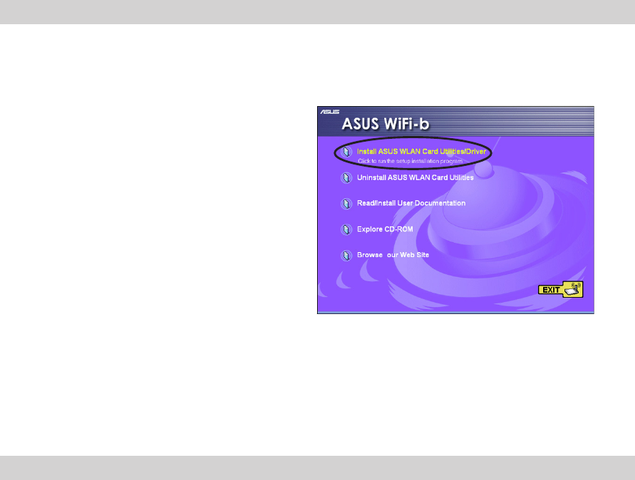
4.3 Software installation
Follow these steps to install the WL-127 card driver and the Control Center Utility.
1. Turn on your computer.
2. Insert the support CD into the CD-ROM drive.
3. Click “Install ASUS WLAN Card Utilities/
Driver” when the ASUS WL-127 installation
window appears.
4. Restart your computer after the device
driver and the Control Center Utility are
installed.
NOTE. If Autorun is NOT enabled in your computer, browse the contents of the
support CD and double click the Setup.exe file to run the CD.
10 ASUS WL-127 Card
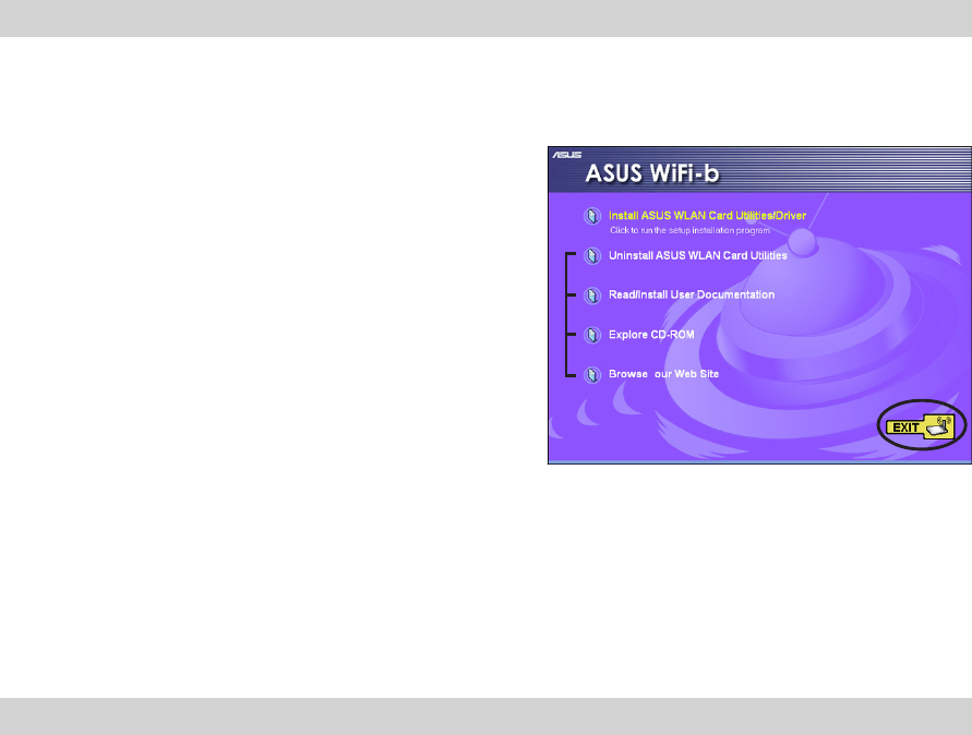
4.3.1 Other support CD contents
The support CD also contains the following options.
Uninstall ASUS WLAN Card Utilities. Click this
option to uninstall the Control Center Utility from
your system.
Read/Install User Documentation. Click to view
the installation and quick setup guides in PDF
format.
Explore CD-ROM. Click this option to explore the
support CD contents.
Browse our Web Site. Click this option to visit
the ASUS website.
Click EXIT to close the installation window.
ASUS WL-127 Card 11
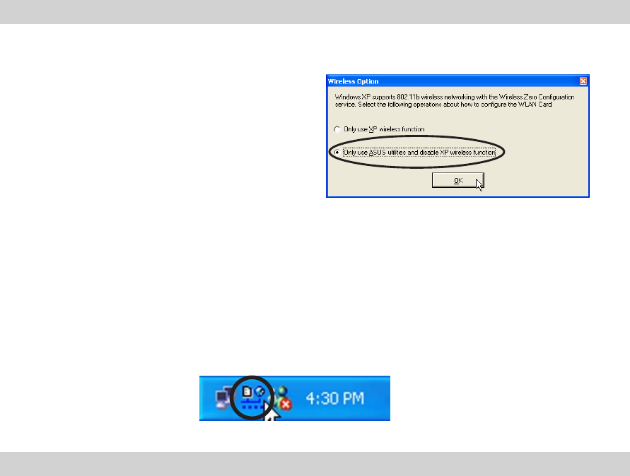
4.4 Windows® XP Wireless Options
The first time that the Control Center Utility is
launched in Windows
®
XP, it will automatically show
the Wireless Options window. Select “Only use
ASUS utilities and disable XP wireless
function” to avail all WL-127 card features.
Click OK.
5. Using the Control Center Utility
The Control Center Utility is a management software that launches applications and activate
network location settings. The Control Center Utility starts automatically when the system
boots and displays an icon in the Windows taskbar. The Control Center icon serves as
application launcher, and indicator of signal quality and Internet connection (see next
section).
12 ASUS WL-127 Card
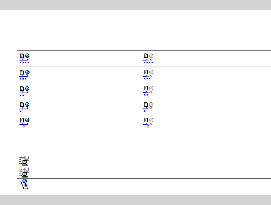
The Control Center icon indicates the quality of link to the Access Point and whether or not the
system is connected to the Internet. Refer to the table below for icon meanings.
Infrastructure Network Mode (WL-127 to an Access Point)
Excellent link quality and Excellent link quality but not
connected to the Internet connected to the Internet
Good link quality and Good link quality but not
connected to the Internet connected to the Internet
Fair link quality and Fair link quality but not
connected to the Internet connected to the Internet
Poor link quality but Poor link quality and not
connected to the Internet connected to the Internet
Not linked but connected Not linked and not
to the Internet connected to the Internet
Ad-Hoc Network Mode (WL-127 to other Wi-Fi device)
Linked
Not Linked
Connected to the Internet
ASUS WL-127 Card 13
5.1 Control Center Right-Click Menu
Right-clicking the Control Center icon
displays the right-click menu. The following
sections describe the right-click menu items.
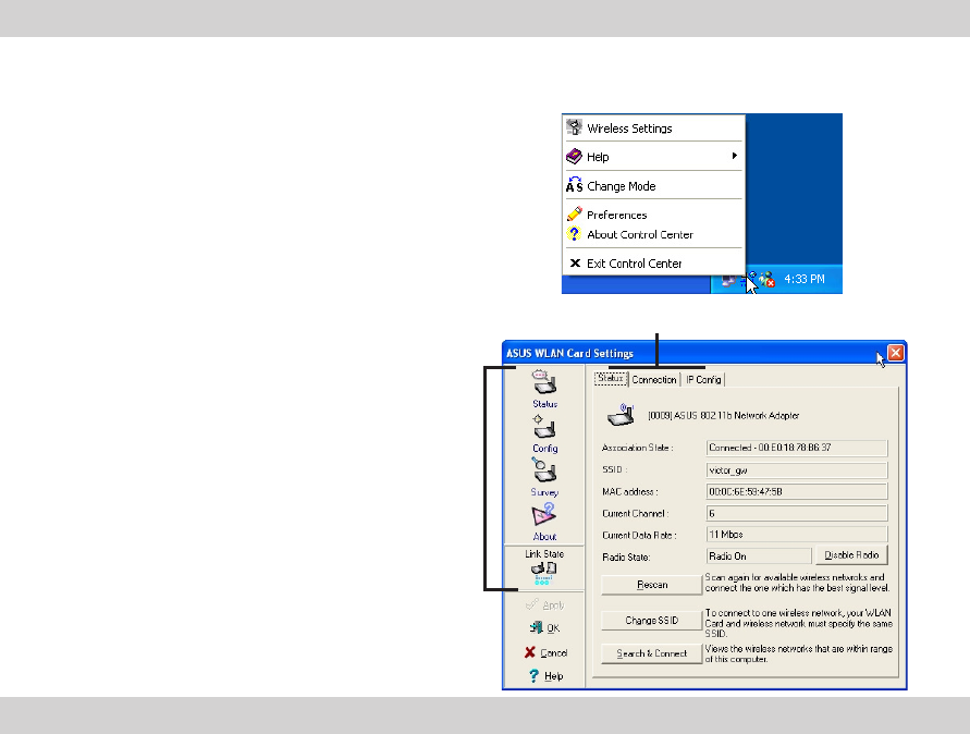
5.1.1 Wireless Settings
The Wireless Settings is the main interface
that allows users to control the ASUS WL-
127. Use the Wireless Settings to view the
operational and connection status, or to
modify the WL-127 configuration.
The Wireless Settings window is composed
of the property window and tabbed property
sheets. Click the icons in the property
window to display their tabbed property
sheets.
Property IWindow
Tabbed Property Sheets
14 ASUS WL-127 Card
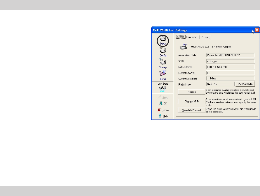
Status - Status Tab
The Status Tab provides general information on
the WL-127 card.
Association State. This field displays the
connection status and MAC address of the
network where the system is connected.
Service Set Identifier (SSID). This field displays
the SSID of the network which the card is
associated or is intending to join. The SSID is a
group name shared by every member of a
wireless network. Only client PCs with the same
SSID are allowed to establish a connection.
The MAC Address field displays the hardware address of a device connected to a network.
The Current Channel field displays the radio channel that the card is currently tuned. The
channel changes as WL-127 scans the available channels. See page 27 for channel information.
The Current Data Rate field displays the data transfer rate between the WL-127 card and
the access point.
ASUS WL-127 Card 15
The Radio State field displays the radio communication status. Click the Disable Radio
button if you wish to disable radio communication with the access point.
Rescan button - Click to allow WL-127 to scan available wireless networks and to connect to
the network with the best signal quality.
Change SSID button - Click to change the SSID. Clicking this button opens the Config-Basic
window. See page 17 for details.
Search and Connect button - Click to view all wireless networks within the range of your
system. Clicking this button opens the Site Survey window. See page 21 for details.
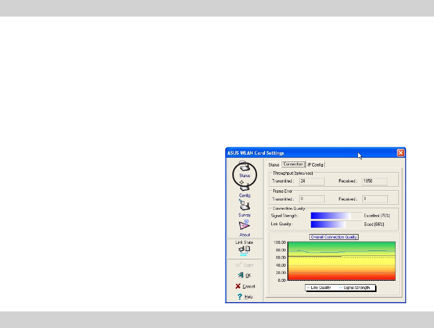
Status - Connection Tab
The Connection Tab provides real-time information
on connection throughput, frame errors, signal
strength, link quality and overall connection quality
in graph representation.
16 ASUS WL-127 Card
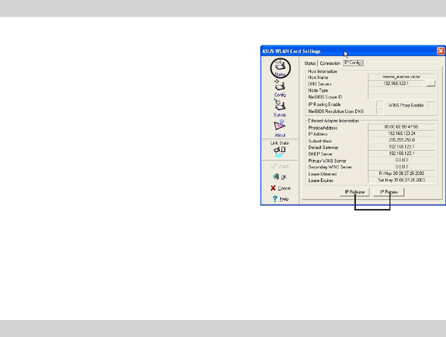
Status - IP Config Tab
The IP Config tab displays the current host and
ethernet adapter configurations. IP Config
displays TCP/IP information including the IP
address, subnet mask, default gateway, DNS and
Windows Internet Naming Service (WINS)
configurations.
Use the IP Config Tab to verify your network
settings.
IP Buttons
IP Release. Click to release the DHCP IP
address for the WL-127 card.
IP Renew. Click to renew the DHCP IP address
for the WL-127 card.
IP Buttons
NOTE. The Dynamic Host Configuration Protocol (DHCP) allows a computer or
computers on a network to be automatically assigned a single IP address from a
DHCP server.
ASUS WL-127 Card 17
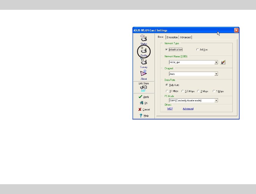
Config - Basic Tab
The Basic tab provides general information on
network types and other configurations.
Network Type. Select which type of network you
wish to use. Select Infrastructure mode to
establish a connection with an Access Point (AP).
In this mode, your system can access wireless
LAN and wired LAN (Ethernet) via the AP. Select
the Ad Hoc mode to communicate directly with
other Wi-Fi devices within the WL-127 operating
range.
Network Name - Displays the network SSID. The
network SSID is a string use to identify a wireless
LAN. Assign different SSIDs to segment the wireless LAN and increase network security. Set
the SSID to a null string to allow your station to connect to any available Access Point. Null
string may not be used in Ad Hoc mode.
Channel. In Infrastructure mode, WL-127 automatically selects the correct frequency
channel. In Ad Hoc mode, select a channel that is allowed for use in your country/region. See
page 27 for channel information.
18 ASUS WL-127 Card
Data Rate. Select Fully Auto to allow WiFi-b to adjust to the most suitable connection. You
may also fix data transfer rates to 11, 5.5, 2 and 1 Mbps.
PS Mode. This field allows control of the WL-127 card power saving features. The CAM
(Constantly Awake mode) is recommended for systems running on AC power.
Others. Click the WEP or Advanced link to open the Encryption or Advanced property tab
sheet.
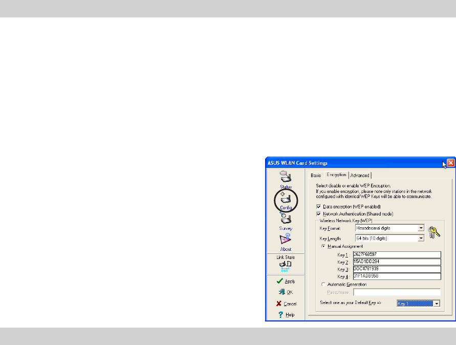
Config - EncryptionTab
Wireless data transmissions between your WL-
127 and the AP are secured using the Wired
Equivalent Privacy (WEP) encryption. Check the
Data encryption (WEP enabled) option to assign
the WEP keys.
Check the Network Authentication (Shared Mode)
option if you wish to use a network key to
authenticate a preferred wireless network.
Unchecking this option allows the network to
operate on an Open System mode.

ASUS WL-127 Card 19
Key Format allows you to set a hexadecimal digit or ASCII character WEP key.
Key Length allows you to choose a 64-bit or a 128-bit WEP key. A 64-bit encryption contains
10 hexadecimal digits or 5 ASCII characters. A 128-bit encryption contains 26 hexadecimal
digits or 13 ASCII characters.
NOTE. 64-bit and 40-bit WEP keys use the same encryption method and can
interoperate on wireless networks. This lower level of WEP encryption uses a 40-bit
(10 hexadecimal digits assigned by the user) secret key and a 24-bit Initialization
Vector assign by the WL-127. 104-bit and 128-bit WEPs uses the same encryption
method.
Two ways to assign WEP keys
Manual Assignment. For a 64-bit encryption, enter 10 hexadecimal digits (0~9, a~f, A~F) in
each of the four WEP keys.
Automatic Generation. Type a combination of up to 64 letters, numbers, or symbols in the
Passphrase field. The Wireless Settings Utility uses an algorithm to generate four WEP keys
based on the typed combination.
20 ASUS WL-127 Card
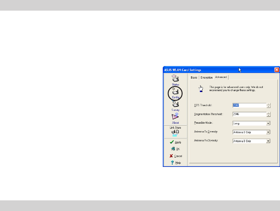
Config - Advanced
The Advanced tab displays the WL-127 card
advance settings. It is recommended that you do
not make any changes on these settings.
NOTE. After assigning the WEP keys, Click APPLY to save and activate the
encryption. Manually assigned encryptions are more secured than automatically
generated encryptions.
ASUS WL-127 Card 21
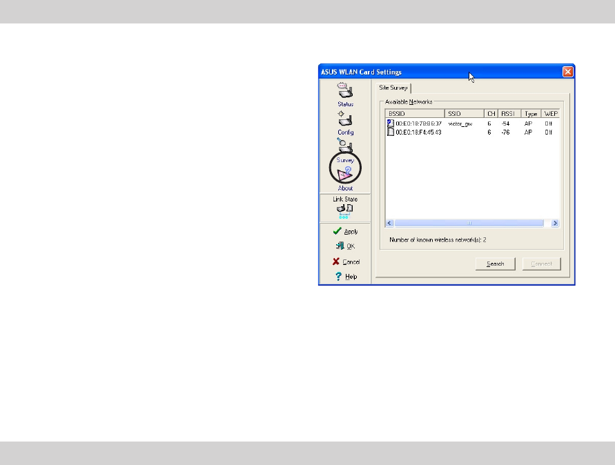
Site Survey
The Site Survey tab displays the available
networks within the range of the WL-127 card.
The following network attributes are displayed:
BSSID - The IEEE MAC address of the network
SSID - SSID (service set identifier) of the
network.
CH - Direct sequence channel used by the
network.
RSSI - Received Signal Strength Indicator (RSSI)
in dBm.
Type - wireless network mode. AP indicates an
Infrastructure network type. STA indicates an
Ad Hoc network type.
WEP - shows whether a network has an enabled (On) or disabled (Off) WEP encryption.
Select an available network and click Connect to establish connection. Click Search to
rescan available networks.
22 ASUS WL-127 Card
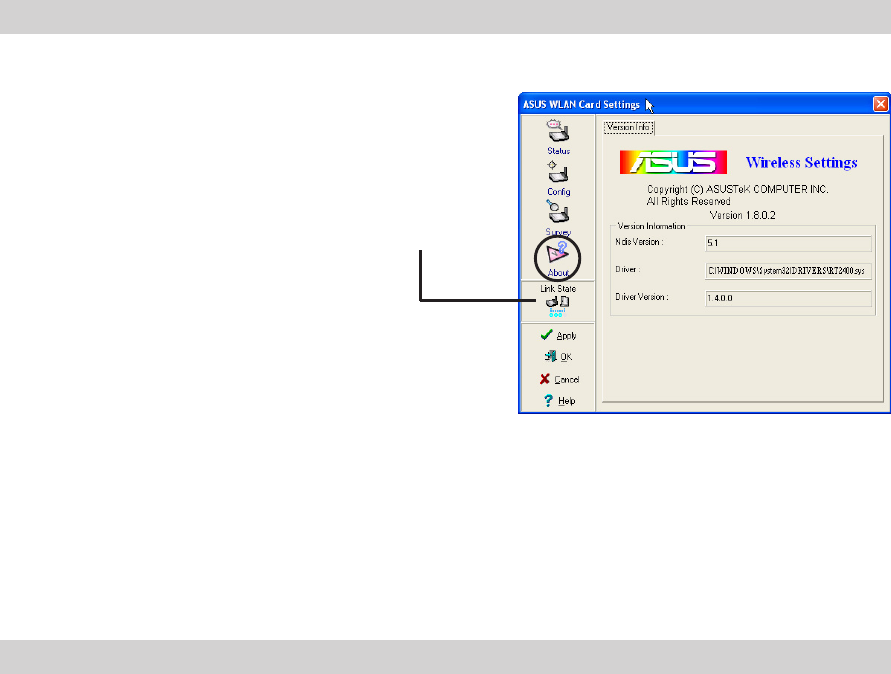
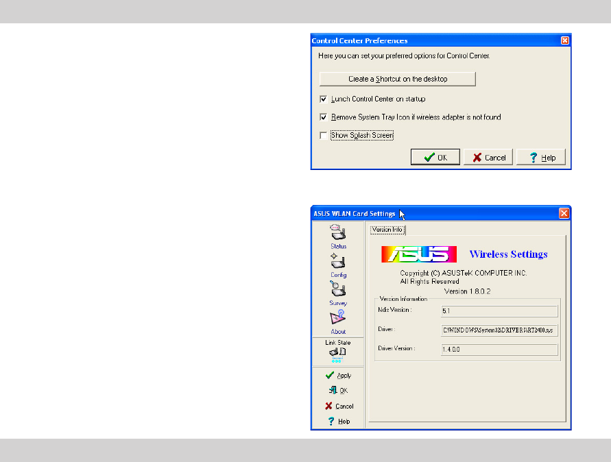
About
Click the About icon to view the software version,
driver version, and copyright information.
Link State
Displays the current connection status of the WL-
127 card to the AP or to other Wi-Fi device.
ASUS WL-127 Card 23
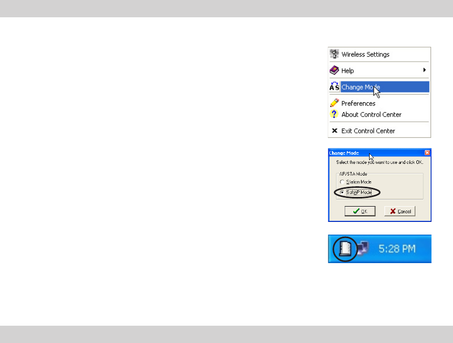
5.1.3 Configuring your system as an Access Point (AP)
The Control Center Utility can configure your system as soft access point (AP). The WL-127
soft AP function can support up to 31 wireless clients. Before configuring your system as soft
AP, make sure your system meets the following requirements:
•Connection to the Internet (cable, DSL, satellite, etc) and wired LAN
•Windows
®
XP operating system
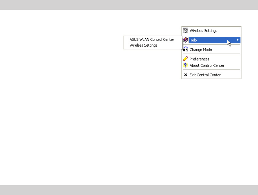
5.1.2 Help Menu
The Control Center Utility is equipped with a
Help menu to guide you in using and
configuring the WL-127 card.
Right-click the Control Center icon on the
taskbar, then select Help. Select the Help
menu you wish to browse.
24 ASUS WL-127 Card
Select SoftAP Mode. Click OK.
The Access Point icon replaces the Control Center icon in
the Windows
®
taskbar.
Follow these instructions to configure your system as soft AP.
Right-click the Control Center icon on the taskbar, then select
Change Mode in the pop-up menu. A Change Mode window
appears.
IMPORTANT. Make sure that the network type of wireless clients is set to
Infrastructure mode. Wireless clients must also have the same SSID with the soft
AP to establish connection.
ASUS WL-127 Card 25
5.1.4 Preferences
The Preferences window allows you to
customize the Control Center Utility settings.
5.1.5 About Control Center
The About Control Center menu displays the
software, drivers, and copyright information.
26 ASUS WL-127 Card
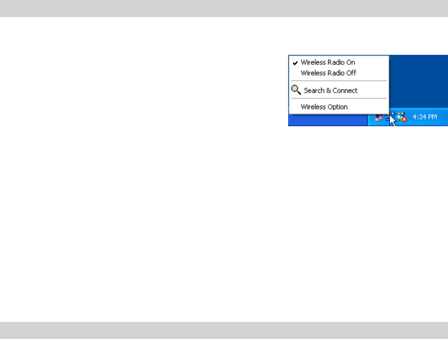
5.2 Control Center Left-Click Menu
Left-clicking the Control Center icon displays the
Left-Click menu. The options are described below.
Wireless Radio On – Turns the WL-127 radio ON.
Wireless Radio Off – Turns the WL-127 radio OFF.
Search & Connect – View available wireless networks within range.
Wireless Option (Windows
®
XP only) – Sets your Windows
®
XP wireless networking
environment. See page 11 for details.
ASUS WL-127 Card 27
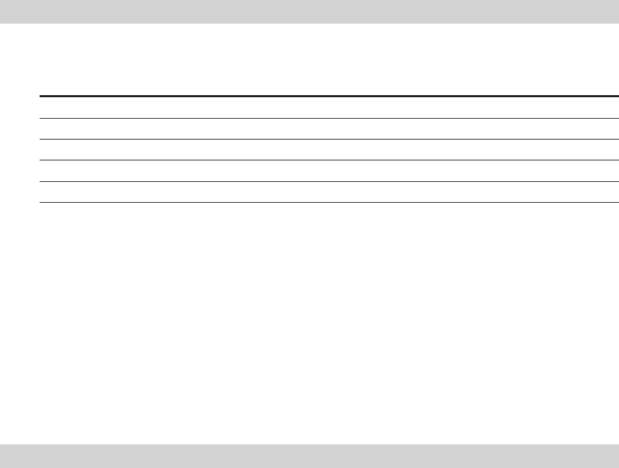
Channel Center Channel Center
Frequency Frequency
1 2.412 GHz 8 2.447 GHz
2 2.417 GHz 9 2.452 GHz
3 2.422 GHz 10 2.457 GHz
4 2.427 GHz 11 2.462 GHz
5 2.432 GHz 12 2.467 GHz
6 2.437 GHz 13 2.472 GHz
7 2.442 GHz 14 2.484 GHz
6. Appendix
6.1 Channels
The IEEE 802.11b standard for Wireless LAN allocated the 2.4 GHz frequency band into 14
overlapping operating channels. Each channel corresponds to a different set of frequencies.
The table below shows the center frequencies of each channel.
IMPORTANT! If several WL-127 devices are operating in the same vicinity, the
distance between the center frequencies of channels used must be at least 25 MHz
to avoid interference.
28 ASUS WL-127 Card
NOTE. Channels 1,6 and 11 are independent and do not overlap each other. It is
recommended to tune your WL-127 card to these channels.
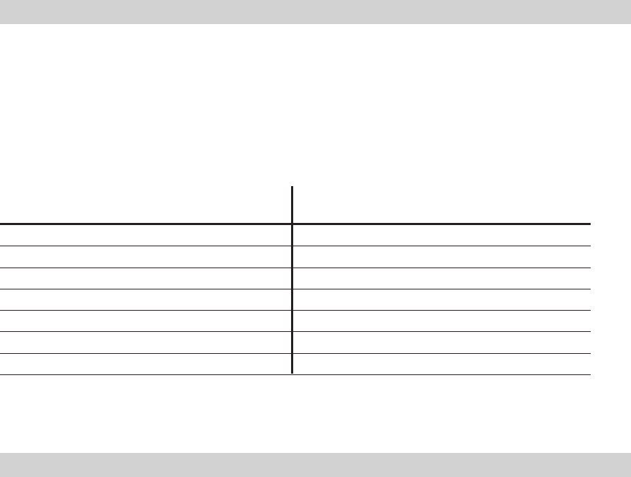
The number of channels available for the WL-127 varies by country/region. Refer to the table
below to determine the number of channels available in your location.
Country/Region Available Channels
United States (FCC) and Canada (IC) Channels 1 to 11
Europe (ETSI) except Spain and France Channels 1 to 13
Spain Channels 10 and 11
France Channels 10 to 13
Japan (MKK) Channels 1 to 14

ASUS WL-127 Card 29
6.2 Safety Information
In order to maintain compliance with the FCC RF exposure guidelines, this equipment should
be installed and operated with minimum distance [20cm] between the radiator and your body.
Use only with supplied antenna. Unauthorized antenna, modification, or attachments could
damage the transmitter and may violate FCC regulations.
CAUTION! Any changes or modifications not expressly approved in this manual
could void your authorization to use this device.
MPE Statement
Your device contains a low power transmitter. When device is transmitted it sends out Radio
Frequency (RF) signal.
Caution Statement of the FCC Radio Frequency Exposure
This Wireless LAN radio device has been evaluated under FCC Bulletin OET 65C and found
compliant to the requirements as set forth in CFR 47 Sections 2.1091, and
15.247(b)(4) addressing RF Exposure from radio frequency devices. The radiation output
power of this Wireless LAN device is far below the FCC radio frequency exposure limits.
Nevertheless, this device shall be used in such a manner that the potential for human contact
during normal operation is minimized. Use in a portable or body-worn configuration is strictly prohibited.

30 ASUS WL-127 Card
prohibited. When using this device, a certain separation distance between antenna and nearby
persons has to be kept to ensure RF exposure compliance. In order to comply with the RF
exposure limits established in the ANSI C95.1 standards, the distance between the antennas
and the user should not be less than [20cm].

ASUS WL-127 Card 31
__________________________________________________________________________________________________________
__________________________________________________________________________________________________________
__________________________________________________________________________________________________________
__________________________________________________________________________________________________________
__________________________________________________________________________________________________________
__________________________________________________________________________________________________________
__________________________________________________________________________________________________________
__________________________________________________________________________________________________________
__________________________________________________________________________________________________________
__________________________________________________________________________________________________________
__________________________________________________________________________________________________________
__________________________________________________________________________________________________________
__________________________________________________________________________________________________________
__________________________________________________________________________________________________________
ASUSTeK COMPUTER INC. (Asia-Pacific)
Marketing Technical Support
Address: 150 Li-Te Road MB/Others (Tel): +886-2-2890-7121 (English)
Peitou, Taipei, Taiwan 112 Notebook (Tel): +886-2-2890-7122 (English)
General Tel.: +886-2-2894-3447 Desktop/Server (Tel): +886-2-2890-7123 (English)
General Fax: +886-2-2894-3449 Support Fax: +886-2-2890-7698
General Email: info@asus.com.tw Web Site: www.asus.com.tw
ASUS COMPUTER INTERNATIONAL (America)
Marketing Technical Support
Address: 44370 Nobel Drive, Fremont, Support Fax: +1-502-933-8713
CA 94538, USA General Support: +1-502-995-0883
General Fax: +1-502-933-8713 Web Site: usa.asus.com
General Email: tmd1@asus.com Support E-mail: tsd@asus.com
ASUS COMPUTER GmbH (Germany and Austria)
Marketing Technical Support
Address: Harkortstr. 25 40880 Ratingen, Support Hotline: Components: +49-2102-9599-0
BRD, Germany Notebook: +49-2102-9599-10
General Fax: +49-2102-9599-31 Support Fax: +49-2102-9599-11
General Email: sales@asuscom.de Support (Email): www.asuscom.de/support
(for marketing requests only) (for online support)
Web Site: www.asuscom.de
ASUS Contact Information