ASUSTeK Computer WL230 WLAN PCI Card with Integral Antenna User Manual SpaceLink PCI Card p65
ASUSTeK Computer Inc WLAN PCI Card with Integral Antenna SpaceLink PCI Card p65
Manual
SpaceLink™ B&W PCI Card
WL230
User’s Manual
®

2ASUS SpaceLink B&W PCI Card
No part of this manual, including the products and software described in it,
may be reproduced, transmitted, transcribed, stored in a retrieval system,
or translated into any language in any form or by any means, except
documentation kept by the purchaser for backup purposes, without the
express written permission of ASUSTeK COMPUTER INC. (“ASUS”).
ASUS PROVIDES THIS MANUAL “AS IS” WITHOUT WARRANTY
OF ANY KIND, EITHER EXPRESS OR IMPLIED, INCLUDING BUT
NOT LIMITED TO THE IMPLIED WARRANTIES OR CONDITIONS
OF MERCHANTABILITY OR FITNESS FOR A PARTICULAR
PURPOSE. IN NO EVENT SHALL ASUS, ITS DIRECTORS, OFFICERS,
EMPLOYEES OR AGENTS BE LIABLE FOR ANY INDIRECT,
SPECIAL, INCIDENTAL, OR CONSEQUENTIAL DAMAGES
(INCLUDING DAMAGES FOR LOSS OF PROFITS, LOSS OF
BUSINESS, LOSS OF USE OR DATA, INTERRUPTION OF BUSINESS
AND THE LIKE), EVEN IF ASUS HAS BEEN ADVISED OF THE
POSSIBILITY OF SUCH DAMAGES ARISING FROM ANY DEFECT
OR ERROR IN THIS MANUAL OR PRODUCT.
Product warranty or service will not be extended if: (1) the product is
repaired, modified or altered, unless such repair, modification of alteration
is authorized in writing by ASUS; or (2) the serial number of the product is
defaced or missing.
Products and corporate names appearing in this manual may or may not be
registered trademarks or copyrights of their respective companies, and are
used only for identification or explanation and to the owners’ benefit, without
intent to infringe.
SPECIFICATIONS AND INFORMATION CONTAINED IN THIS
MANUAL ARE FURNISHED FOR INFORMATIONAL USE ONLY, AND
ARE SUBJECT TO CHANGE AT ANY TIME WITHOUT NOTICE, AND
SHOULD NOT BE CONSTRUED AS A COMMITMENT BY ASUS. ASUS
ASSUMES NO RESPONSIBILITY OR LIABILITY FOR ANY ERRORS
OR INACCURACIES THAT MAY APPEAR IN THIS MANUAL,
INCLUDING THE PRODUCTS AND SOFTWARE DESCRIBED IN IT.
Copyright © 2002 ASUSTeK COMPUTER INC. All Rights Reserved.
Copyright Information
Product Name: SpaceLink B&W PCI Card (WL230)
Manual Revision: 1 E1165
Release Date: December 2002

ASUS SpaceLink B&W PCI Card 3
Copyright Information
ASUSTeK COMPUTER INC. (Asia-Pacific)
Address: 150 Li-Te Road, Peitou, Taipei, Taiwan 112
General Tel: +886-2-2894-3447
General Fax: +886-2-2894-3449
General Email: info@asus.com.tw
Technical Support
MB/Others (Tel):+886-2-2890-7121 (English)
Notebook (Tel): +886-2-2890-7122 (English)
Desktop/Server: +886-2-2890-7123 (English)
Support Fax: +886-2-2890-7698
Support Email: tsd@asus.com.tw
Web Site: www.asus.com.tw
Newsgroup: cscnews.asus.com.tw
ASUS COMPUTER INTERNATIONAL (America)
Address: 6737 Mowry Avenue, Mowry Business Center,
Building 2, Newark, CA 94560, USA
General Fax: +1-510-608-4555
General Email: tmd1@asus.com
Technical Support
Support Fax: +1-510-608-4555
General Support: +1-502-933-8713
Web Site: www.asus.com
Support Email: tsd@asus.com
ASUS COMPUTER GmbH (Germany & Austria)
Address: Harkortstr. 25, 40880 Ratingen, BRD, Germany
General Fax: +49-2102-442066
General Email: sales@asuscom.de (for marketing requests only)
Technical Support
Support Hotline: MB/Others: +49-2102-9599-0
Notebook (Tel): +49-2102-9599-10
Support Fax: +49-2102-9599-11
Support (Email): www.asuscom.de/de/support (for online support)
Web Site: www.asuscom.de

4ASUS SpaceLink B&W PCI Card
Table of Contents
1. Introduction ............................................................................. 7
Overview .............................................................................................. 7
The SpaceLink™ Family ...................................................................... 8
System Requirements .......................................................................... 9
The Product Package ........................................................................... 9
ASUS SpaceLink B&W PCI Card Layout ........................................... 10
LED Definitions .......................................................................... 10
ASUS SpaceLink B&W Specifications ....................................... 11
2. Installation ............................................................................. 12
2.1 Installing the ASUS SpaceLink B&W PCI Card ......................... 12
Blue Magic PCI Slot ................................................................... 13
Non-Blue Magic PCI Slot ........................................................... 13
2.2 Installing the SpaceLink PCI Driver ........................................... 14
2.3 Verifying Drivers ......................................................................... 15
2.4 Installing the SpaceLink Utilities ................................................ 16
2.5 Installing the SpaceLink Bluetooth ............................................. 17
3. Wireless LAN Reference ...................................................... 19
3.1 Overview .................................................................................... 19
3.2 Windows XP Wireless Options .................................................. 20
3.3 Control Center............................................................................ 21
3.4 Wireless Settings ....................................................................... 23
More than one ASUS SpaceLink Card....................................... 24
3.5 Status - Status Tab..................................................................... 24
Association State ....................................................................... 25
SSID........................................................................................... 25
Network Type ............................................................................. 25
Current Channel......................................................................... 25
MAC address ............................................................................. 25
Transmit Rate ............................................................................ 25
Receive Rate ............................................................................. 25
Security ...................................................................................... 27
Power Save State ...................................................................... 27
Radio State ................................................................................ 27
3.6 Save as Profile ........................................................................... 27
3.7 Activate Configuration ................................................................ 27
3.8 Status - Connection Tab............................................................. 28

ASUS SpaceLink B&W PCI Card 5
Table of Contents
Frame Sent/Received ................................................................ 28
Frame Error................................................................................ 28
Connection Quality..................................................................... 28
Overall Connection Quality ........................................................ 28
Frame Statistics ......................................................................... 29
3.9 Status - IP Config Tab ................................................................ 30
3.10 Config - Basic Tab ...................................................................... 31
Power Saving ............................................................................. 32
Transmit Power .......................................................................... 32
Wireless Mode ........................................................................... 32
Data Rate ................................................................................... 33
3.11 Encryption .................................................................................. 34
Selecting Encryption Types (Enable AES or WEP).................... 34
Default Key ................................................................................ 34
Key Length ................................................................................. 35
Unique Key ................................................................................ 35
Shared Key ................................................................................ 35
Two ways to assign Shared Keys .............................................. 35
3.12 Config - Advanced Tab ............................................................... 37
Channel...................................................................................... 37
Start Ad Hoc Network................................................................. 37
Scan Mode ................................................................................. 37
QoS ............................................................................................ 38
2.4 GHz Preamble ..................................................................... 38
3.13 Survey - Site Survey Tab ........................................................... 39
3.14 About - Version Info Tab............................................................. 40
3.15 Link Status ................................................................................. 41
3.16 Mobile Manager ......................................................................... 42
Main Window ............................................................................. 43
Using New Configuration Wizard ............................................... 46
Using Edit Configuration ............................................................ 47
Encryption .................................................................................. 49
Site Monitor ................................................................................ 55
Starting Site Monitor .................................................................. 55
Main Screen ............................................................................... 55
Monitor ....................................................................................... 56
3.17 Windows XP Wireless Properties ............................................... 57

6ASUS SpaceLink B&W PCI Card
Chapter 1 - Introduction
Chapter 1
Bluetooth Reference .................................................................. 59
Introduction to Bluetooth .................................................................... 59
Bluetooth Dongle ................................................................................ 60
Using the Bluetooth Software ............................................................. 61
Bluetooth Connection Wizard ............................................................. 62
Explore ............................................................................................... 63
Setup .................................................................................................. 64
Security ...................................................................................... 64
Configuration.............................................................................. 64
Services.............................................................................................. 65
Fax ............................................................................................. 66
Network Access ......................................................................... 66
Serial Port .................................................................................. 66
Dial-Up Networking .................................................................... 66
Inbox .......................................................................................... 66
File Transfer (to Public Folder) ........................................................... 67
Bluetooth Cellular Phone.................................................................... 68
Dial-Up Networking with Bluetooth Cellular Phone .................... 69
5. Troubleshooting .................................................................... 70
6. Glossary................................................................................. 72
IEEE 802.11b (11Mbits/sec) ............................................................... 76
Direct-Sequence Spread Spectrum (for 802.11b) .............................. 77
IEEE 802.11a (54Mbits/sec) ............................................................... 78
COFDM (for 802.11a) ......................................................................... 79
7. Safety Information ................................................................ 80
Federal Communications Commission Statement ............................. 80
Canadian Department of Communications ........................................ 81
Regulatory information / Disclaimers.................................................. 81
MPE Statement (Safety Information).................................................. 81
Safety Information .............................................................................. 81
Caution Statement of the FCC Radio Frequency Exposure............... 82
SAR Exposure .................................................................................... 82
Radio Frequency Interference Requirements .................................... 82

ASUS SpaceLink B&W PCI Card 7
Chapter 1 - Introduction
Chapter 1
1. Introduction
Overview
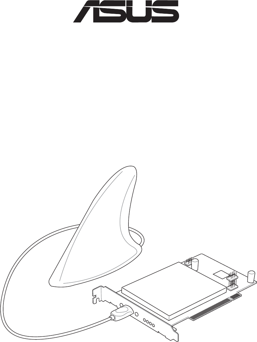
Thank you for purchasing the ASUS SpaceLink B&W PCI Card. The ASUS
SpaceLink B&W PCI Card is a PCI compliant “wireless” network interface
card (NIC) for any computer equipped with a PCI slot. For Bluetooth support,
you must also have an ASUS motherboard equipped with a Blue Magic PCI
slot or any motherboard with a USB 2.0 header. The Blue Magic PCI slot has
USB 2.0 built into the slot.
ASUS SpaceLink B&W PCI Card is designed to be fully compliant with both
the IEEE 802.11b and IEE802.11a wireless local area network (Wireless LAN)
standards as well as Bluetooth for interconnecting personal devices. As a result
of the completion of the standard, the interoperability of Wireless LAN products
among multiple manufacturers will be guaranteed. The ASUS SpaceLink B&W
PCI Card product provides high-speed, standards-based Wireless LAN
solutions. The ASUS SpaceLink B&W PCI Card can auto-switch between
802.11b and 802.11a networks, while maintaining Bluetooth connectivity.
The ASUS SpaceLink B&W PCI Card supports data rates up to 11 Mbps, with
automatic fallback to 5.5, 2, and 1 Mbps in 802.11b networks. It operates in the
unlicensed 2.4 GHz frequencies called the Instrumentation, Science, and
Medical (ISM) band. Unlicensed means free of charge to users.
The ASUS SpaceLink B&W PCI Card also supports data rates up to 54 Mbps
in 802.11a networks using 5 GHz frequencies and Orthogonal Frequency
Division Multiplexing (OFDM) technology.
The ASUS SpaceLink B&W PCI Card configuration utility is a user-friendly
application that helps you quickly setup multiple roaming nodes using the ASUS
SpaceLink B&W PCI Card. You can even export the configuration settings to
a file and import them to other computers for fast multiple installations. Wireless
LANs are complementary extensions to existing wired LANs, offering complete
mobility while maintaining continuous network connectivity to both corporate
and home Intranets. They add a new level of convenience for LAN users. PC
users stay connected to the network anywhere throughout a building without
being bound by a LAN wires. This is accomplished through the use of SpaceLink
Access Points. SpaceLink Access Points with built-in Internet gateway
capability, allows your family to share a broadband Modem and one ISP account
simultaneously from different rooms without wires! ASUS SpaceLink products
can keep you connected anywhere, any time.
8ASUS SpaceLink B&W PCI Card
Chapter 1 - Introduction
Chapter 1
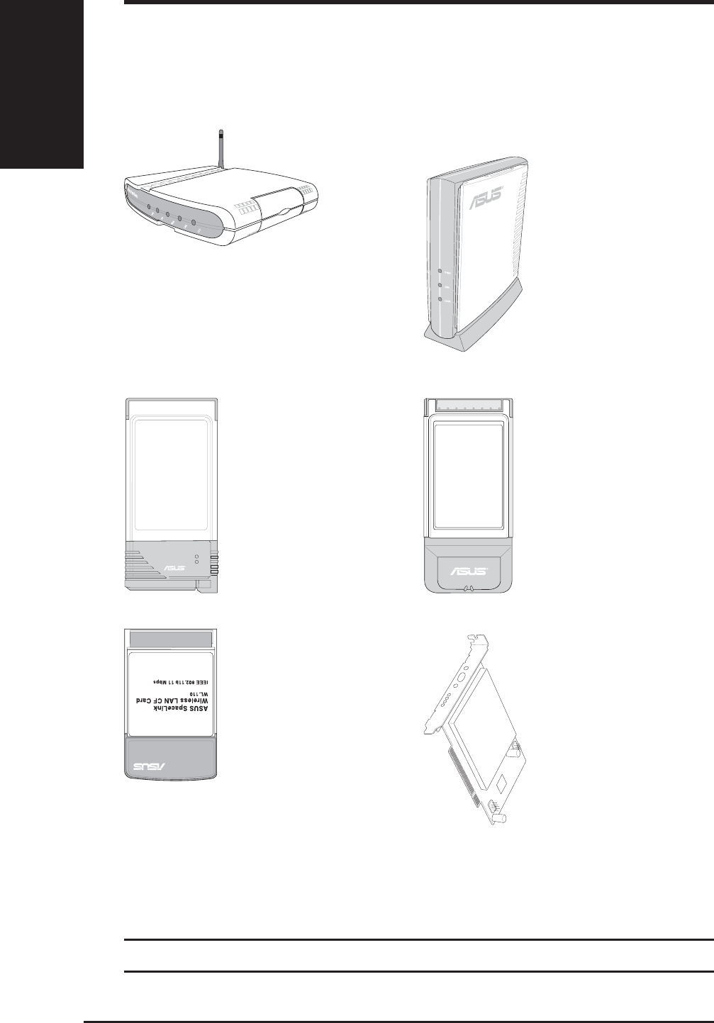
The SpaceLink™ Family
The SpaceLink™ Wireless PCI Card is a member of a product family that
provides a complete wireless networking solution.
The above illustrations are not to scale.
The SpaceLink™
Cardbus Card (WL-
200) is a dual band (IEEE
802.11a/b) wireless LAN
adapter that fits into a
Notebook PC’s
PCMCIA Type II slot
with Cardbus support.
LNK
AIR
The SpaceLink™
PC Card (WL-100)
is a wireless LAN
adapter that fits into
a PCMCIA Type II
slot in a Notebook
PC.
The SpaceLink™
CF Card (WL-110)
is a wireless LAN
adapter that fits into
a Compact Flash
Type II slot in a
Portable Digital
Assistant (PDA).
The SpaceLink™
Access Point (WL-
300) creates a wireless
network using the
IEEE 802.11b
wireless standard.
The SpaceLink™ Gateway (WL-
500) creates a wireless network using
the IEEE 802.11b wireless standard
and allows sharing a single Internet
connection.
The SpaceLink™
PCI Card (WL230)
is a dual band/dual
mode wireless PCI
card that supports
IEEE 802.11a,
802.11b, and
Bluetooth.

ASUS SpaceLink B&W PCI Card 9
Chapter 1 - Introduction
Chapter 1
System Requirements
To begin using the SpaceLink™ Wireless PCI Card, you must have the
following minimum requirements:
• An ASUS motherboard with the Blue Magic PCI slot
• Windows XP/2000/ME/98SE
• 32MB system memory or larger
• 300MHz processor or higher
As of the writing of this manual, the following motherboards have the Blue
Magic PCI slot: A7V8X, P4PE, P4G8X, P4GE-V. Please visit the ASUS
Web Site for updated information.
The Product Package
When you receive the Wireless LAN package, it should contain the
following items:
• One SpaceLink™ Wireless PCI Card (WL230) with Antenna
• One SpaceLink™ Wireless PCI Card (WL230) User’s Manual
• One Support CD (tools and documentation)
ASUS WLAN Control Center
Mobile Manager
Site Monitor
TroubleShooting
ASUS Bluetooth Software
If any of the above items are not included or damaged, contact your
local dealer for instructions.
10 ASUS SpaceLink B&W PCI Card
Chapter 1 - Introduction
Chapter 1
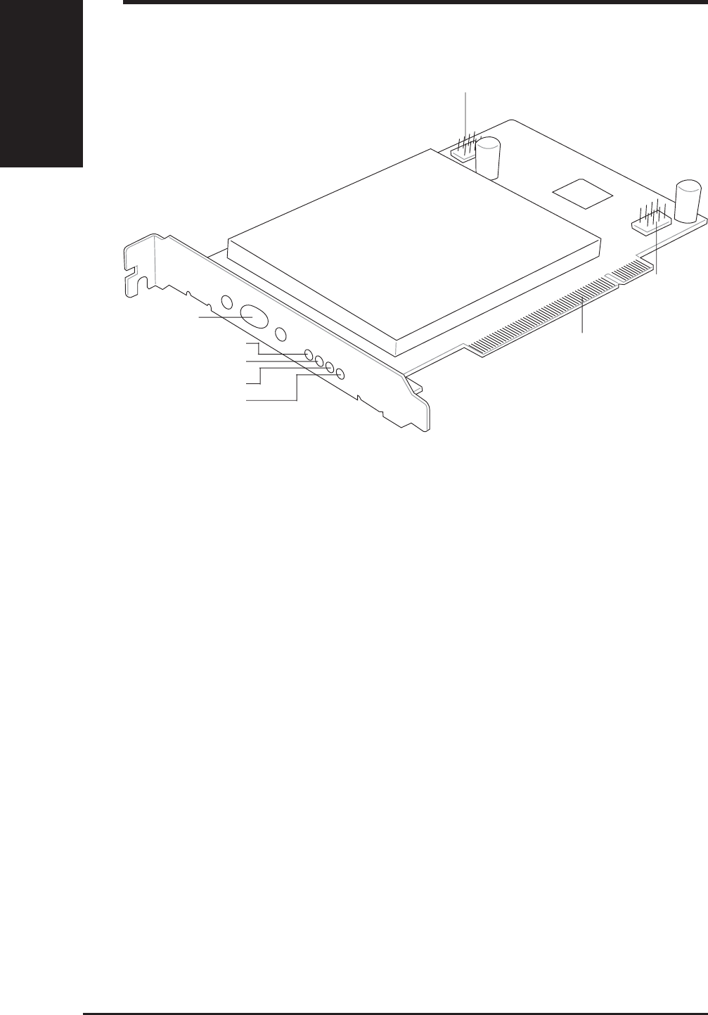
ASUS SpaceLink B&W PCI Card Layout
USB 2.0 Out (up to 2 ports)
USB 2.0 In
Status
Activity
Transmit
Receive
Antenna Port
ASUS BlueMagic PCI
LED Definitions
Receive LED:
Blink - Receiving data packets
OFF - No data packets received
Transmit LED:
Blink - Transmitting data packets
OFF - No data packets transmitted
Activity LED Status LED Meaning
Fast Blink Fast Blink Associated or joined with network
Slow Blink Slow Blink Associated or joined with network, no activity
Alternating Alternating Searching for network connection
OFF Slow Blink Power save mode (Power-Up or Reset)
OFF OFF No power received

ASUS SpaceLink B&W PCI Card 11
Chapter 1 - Introduction
Chapter 1
ASUS SpaceLink B&W Specifications
Industry Standards: Bluetooth, IEEE802.11a, IEEE802.11b
Host Interface: ASUS BlueMagic PCI
Antenna: Integrated Bluetooth and dual-band wireless LAN
Bluetooth
Operating Freq: 2.4GHz to 2.5GHz
Data Rate: 1 Mbps
Range: Up to 10 meters
Architecture: Piconet, scatter net
IEEE802.11a
Operating Freq: 5.15GHz to 5.35GHz, 5.725GHz to 5.85GHz
Data Rate: 54, 48, 36, 24, 12, 9, 6Mbps, turbo mode up to 108Mbps
Range: Indoor: 12 meters @ 11Mbps, 50 meters @ 6Mbps
Outdoor: 30 meters @ 54Mbps, 150 meters @ 6Mbps
Architecture: Infrastructure and Ad-Hoc
IEEE802.11b
Operating Freq: 2.4GHz to 2.5GHz
Data Rate: 11, 5.5, 2, 1Mbps
Range: Indoor: 30 meters @ 11Mbps, 90 meters @ 2Mbps
Outdoor: 150 meters @ 11Mbps, 300 meters @ 2Mbps
Architecture: Infrastructure and Ad-Hoc
12 ASUS SpaceLink B&W PCI Card
Chapter 2 - Installation
Chapter 2
2. Installation
This chapter explains how to install the ASUS SpaceLink B&W PCI Card
hardware, drivers, and utilities. This product is designed to operate in
Windows Me, 2000, and XP. Examples in this manual will be that of
Windows XP.
Complete the following steps to install the ASUS SpaceLink B&W PCI
Card.
1. Install the ASUS SpaceLink B&W PCI Card.
2. Install the ASUS SpaceLink B&W PCI Card Driver
3. Install the ASUS SpaceLink B&W PCI Card Utilities
2.1 Installing the ASUS SpaceLink B&W PCI Card
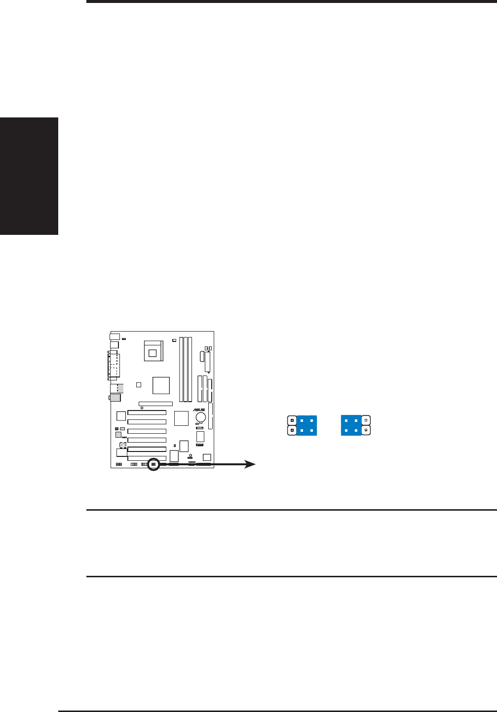
1. Turn OFF your computer and open your computer chassis.
2. Locate the WPCI_USB* jumpers and move them to “Wireless
PCI_USB”
P4PE
®
P4PE WPCI_USB Setting
WPCI_USB
Wireless
PCI_USB
(Default)
35
46
1
3
24
Original
PCI
reserved pi
n
*This is one motherboard example only and may not correctly re-
flect your motherboard. See your User’s Manual for correct infor-
mation regarding the name, location, and use of these jumpers on
your motherboard.
ASUS SpaceLink B&W PCI Card 13
Chapter 2 - Installation
Chapter 2
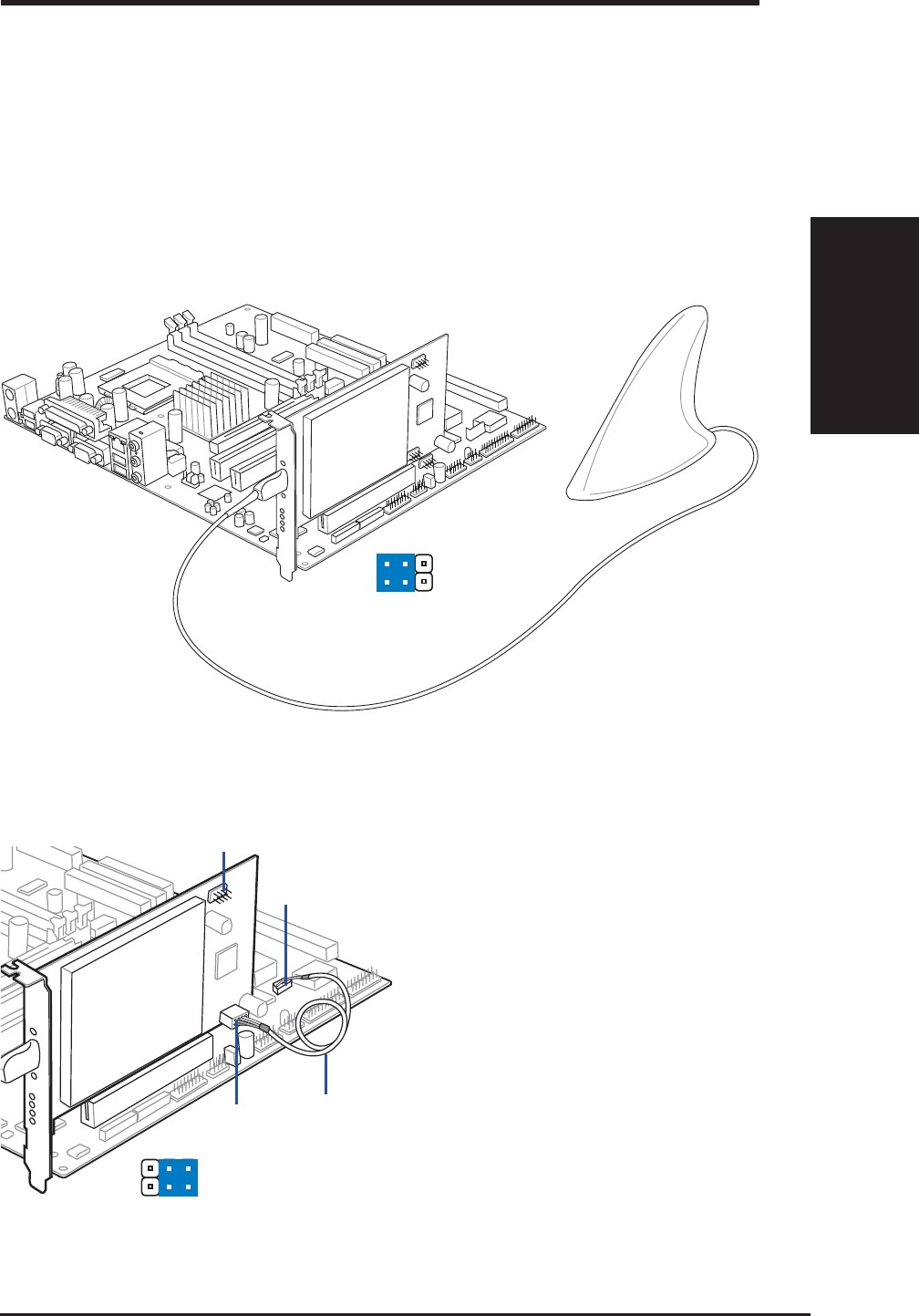
3. Insert the ASUS SpaceLink B&W PCI Card into a Blue Magic PCI
slot.
4. Attach the antenna to the ASUS SpaceLink B&W PCI Card as shown.
2.1 Installing the ASUS SpaceLink B&W PCI Card (Cont.)
If inserting the ASUS SpaceLink
B&W PCI Card into a non-Blue
Magic PCI slot, a USB 2.0
header on the motherboard or
USB 2.0 PCI card is required.
Connect the provided USB cable
from the ASUS SpaceLink
B&W PCI Card (USB 2.0 IN)
to the USB 2.0 OUT header on
the motherboard or PCI card.
You can still use the USB 2.0
port by connecting your USB
bracket to the USB 2.0 OUT on
the ASUS SpaceLink B&W PCI
Card.
Non-Blue Magic PCI Slot
35
46
USB 2.0 Out
USB Cable
USB 2.0 Out (SpaceLink)
1
3
24
USB 2.0 Out (MB)
USB 2.0 In
Blue Magic PCI Slot
14 ASUS SpaceLink B&W PCI Card
Chapter 2 - Installation
Chapter 2
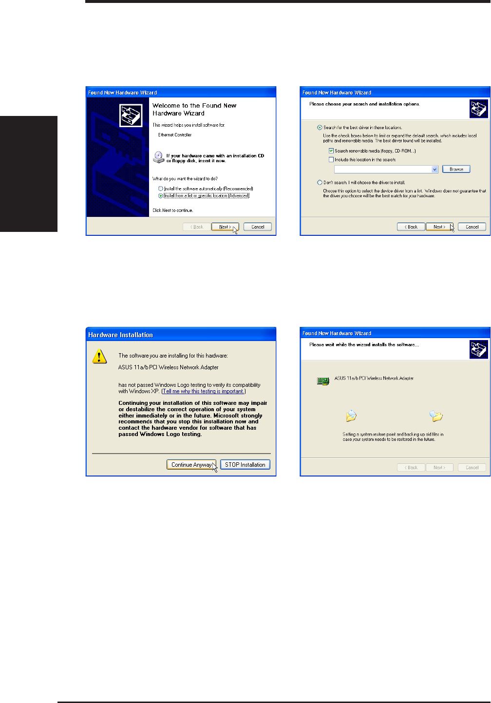
2.2 Installing the SpaceLink PCI Driver
With the SpaceLink B&W PCI Card installed, turn ON your computer and
enter Windows.
1. Windows will automatically detect the ASUS
SpaceLink B&W PCI Card once it is inserted
into the PCMCIA slot, then the “Add New
Hardware Wizard” dialog will appear. Click
Next.
2. Insert the support CD that came with your
ASUS SpaceLink B&W PCI Card .
3. Select “Search for the best driver in”...
“Search removable media...” Click Next.
4. When asked about driver compatibility with
Windows XP. Click Continue Anyway
since ASUS has always tests its drivers
before product shipment.
5. Wait while Windows XP creates a restore
point for you system files in case you need
to restore your current system.
ASUS SpaceLink B&W PCI Card 15
Chapter 2 - Installation
Chapter 2
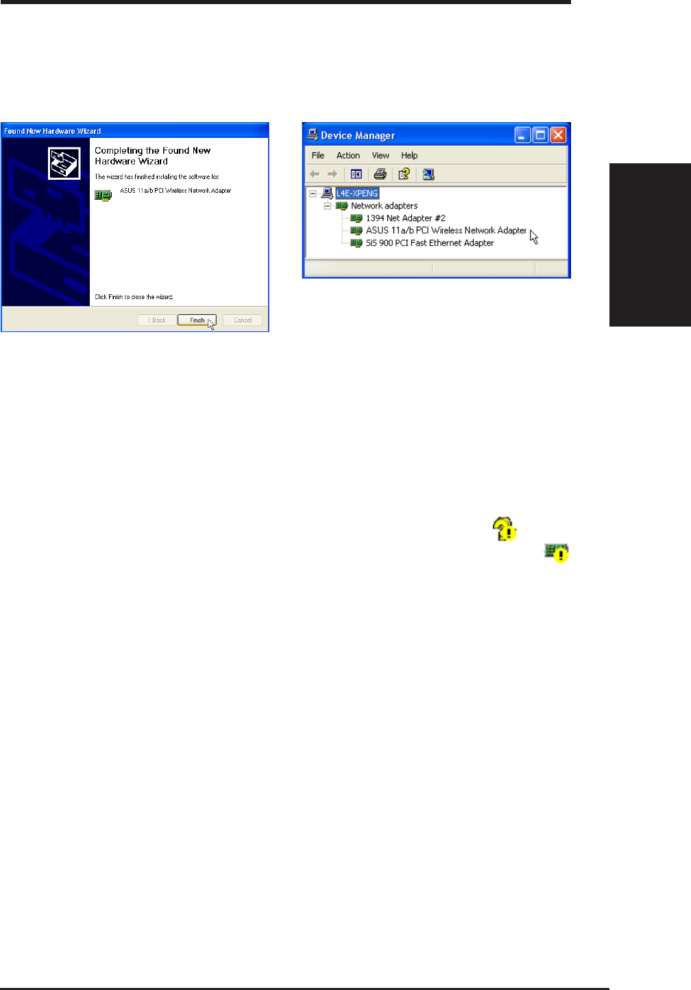
6. Click Finish when installation has complete.
Restart your computer if prompted.
2.3 Verifying Drivers
You can verify the driver in Device Manager. (Access Device Manager
from Start | Control Panel | System | Hardware). A question mark means
that no driver has been installed. An exclamation mark over a card
means that the driver is incorrect. Verify that you are using the correct
product and driver CD. Try repeating the installation and contact customer
support if necessary.
7. You can verify the “ASUS 11a/b PCI Wireless
Network Adapter” driver in Device Manager.
2.2 Installing the SpaceLink PCI Driver (Cont.)
16 ASUS SpaceLink B&W PCI Card
Chapter 2 - Installation
Chapter 2
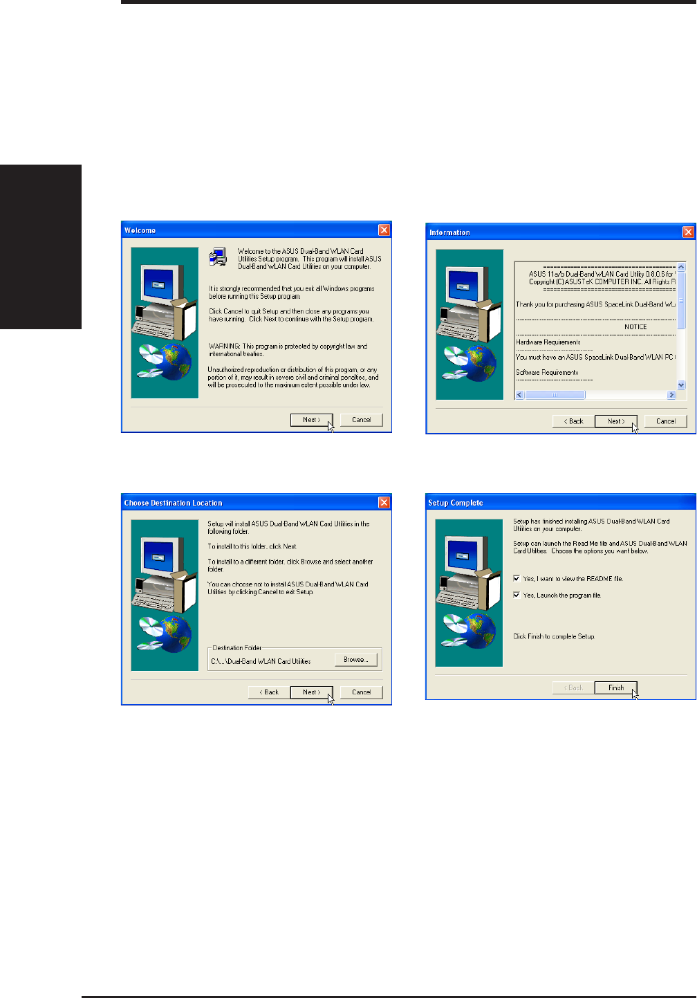
2.4 Installing the SpaceLink Utilities
After you have installed the ASUS SpaceLink B&W PCI Card driver, you
can install the wireless utilities.
1. Insert the ASUS SpaceLink B&W PCI Card support CD and an autorun menu will appear. If
your autorun is disabled, double click SETUP.EXE in the root directory of the support CD.
2. From the autorun menu, click Install ASUS Dual-Band WLAN Card Utilities.
1. Click Next on the Welcome screen. 2. Click Next after reading the Information.
3. Click Next to use the default Destination
Folder or click Browse to select another
folder.
4. Click Finish after setup is complete.
ASUS SpaceLink B&W PCI Card 17
Chapter 2 - Installation
Chapter 2
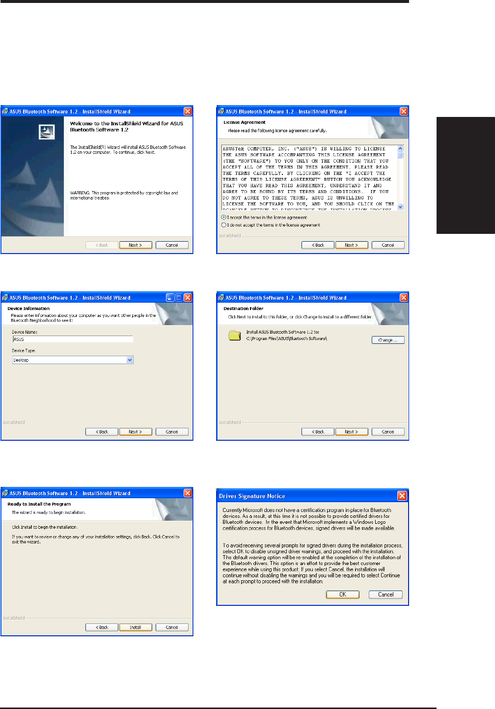
2.5 Installing the SpaceLink Bluetooth
The SpaceLink Bluetooth requires the installation of the Samsung Bluetooth
Software. After installation, you will find the PDF User Manual in
“XTNDConnect Blue Manager” folder.
1. Click Next to begin. 2. Click Next after reading the License
Agreement and selecting “I accept...”.
3. Select your computer type: Desktop 4. Click Next to accept the destination folder
or click “Change” to specify another folder.
5. Click Install when ready to install the
software. 6. Click OK after reading the driver notice.
18 ASUS SpaceLink B&W PCI Card
Chapter 2 - Installation
Chapter 2
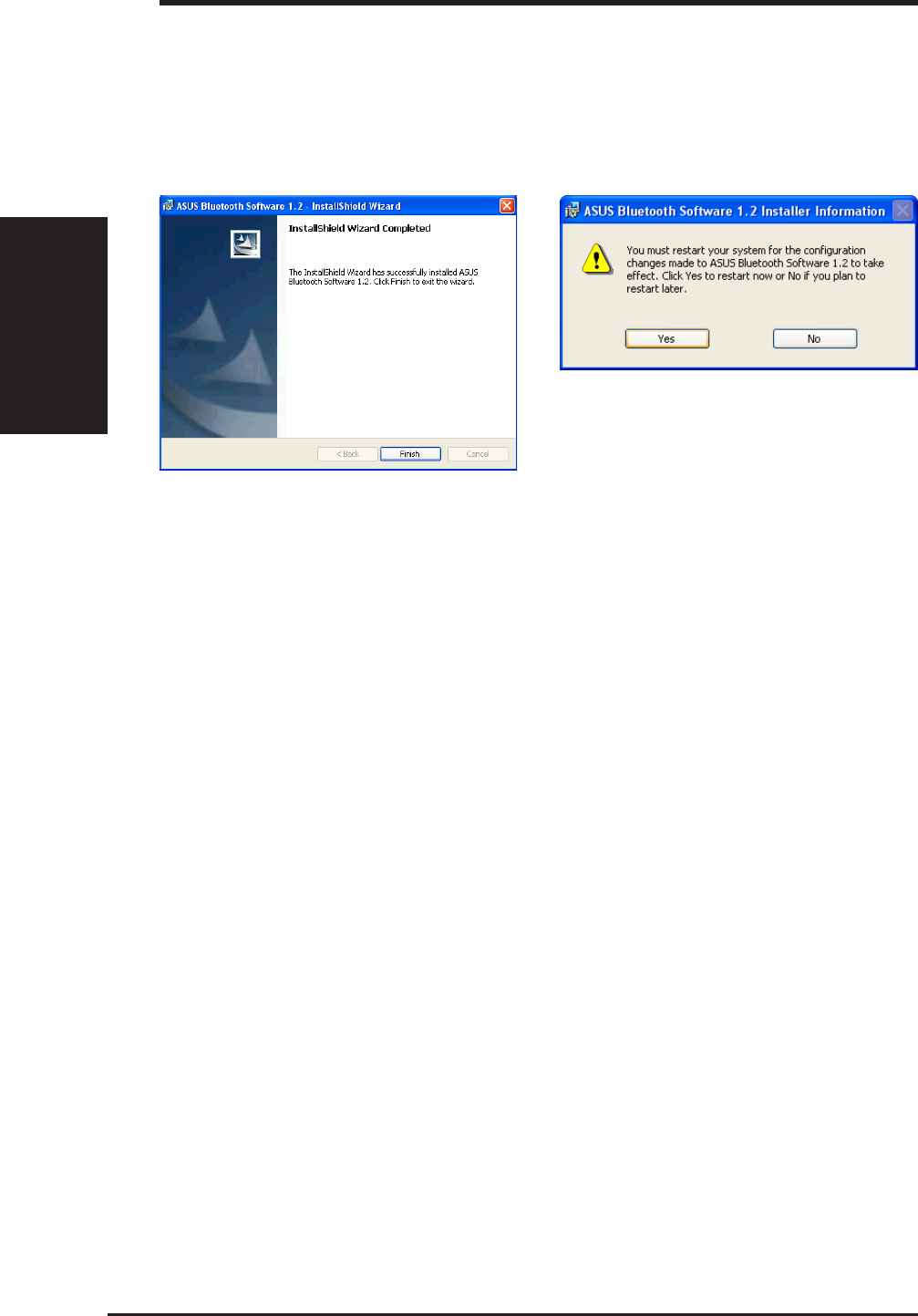
2.5 Installing the SpaceLink Bluetooth (Cont.)
7. Click Finish when installation is complete. 8. Click Yes to restart your computer.

ASUS SpaceLink B&W PCI Card 19
Chapter 3 - Wireless LAN Reference
Chapter 3
3. Wireless LAN Reference
3.1 Overview
The ASUS SpaceLink B&W PCI Card software includes five groups of
utilities.
•Control Center – Makes it easy to launch applications and activate
network location settings.
•Mobile Manager – A convenient tool to setup and manage network
location settings.
•Site Monitor – Measures the received signal strength indicator (RSSI)
values of all wireless networks. This tool is used for determining the
best placement of Access Points to provide the most efficient coverage
in a wireless network.
•Troubleshooting - Troubleshooting will test your settings and connec-
tion to try to pinpoint your problem and give you a solution.
•Wireless Settings – Allows users to control the ASUS SpaceLink B&W
PCI Card.
20 ASUS SpaceLink B&W PCI Card
Chapter 3 - Wireless LAN Reference
Chapter 3
3.2 Windows XP Wireless Options
The wireless options shown below is only available for Windows XP. The
first time you run the Control Center utility, it will automatically show.
Select one of the radio buttons to decide which interface to use with your
SpaceLink B&W PCI Card.
Only use XP wireless function – Only use “Windows XP” wireless network
settings to configure the ASUS SpaceLink B&W PCI Card.
Only use ASUS utilities and disable XP wireless function – Only use
“ASUS SpaceLink B&W PCI Card utilities” to configure the ASUS
SpaceLink B&W PCI Card.
You can return to the Wireless Option setting at any time by left clicking
the control center icon and choosing “Wireless Option”.
Taskbar Left-Click Menu
ASUS SpaceLink B&W PCI Card 21
Chapter 3 - Wireless LAN Reference
Chapter 3
3.3 Control Center
Control Center is an application that makes it easy to launch applications
and activate network location settings. Control Center starts automatically
when the system boots. Whenever Control Center is running, you will see
a Control Center icon displayed on the Windows taskbar.
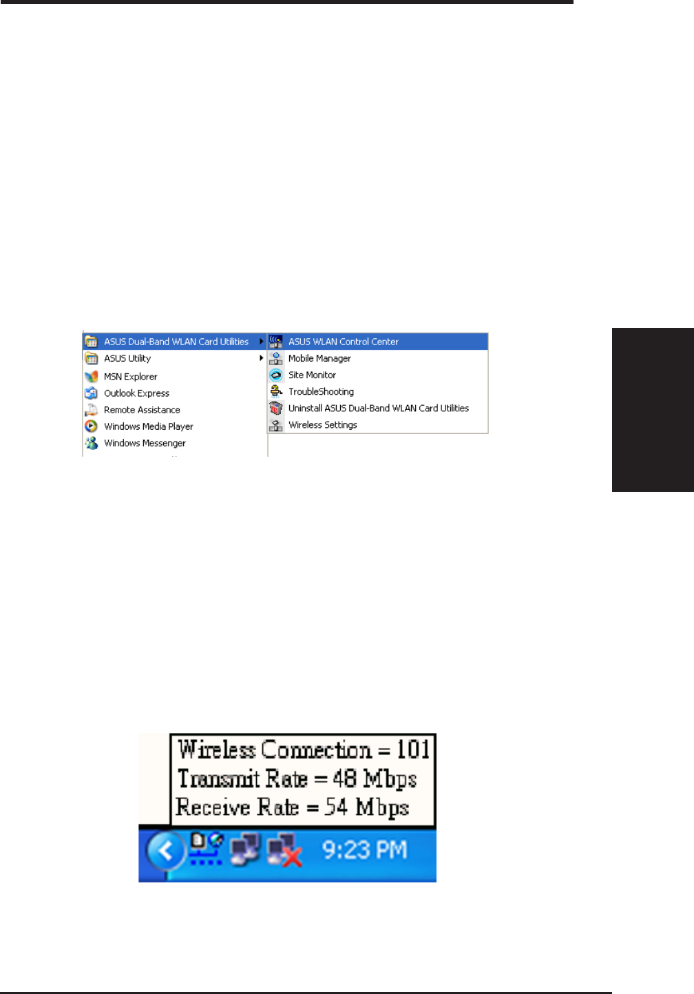
Starting the Control Center manually
• Click the Windows Start button, select Programs, select ASUS Dual-
Band WLAN Card Utilities, and then click ASUS WLAN Control
Center.
or
• Double click the Control Center icon on the desktop.
Windows Start Menu - Programs
Using the Control Center Taskbar
The Control Center Taskbar menu display the following information:
• The link quality of the ASUS SpaceLink B&W PCI Card (Excel-
lent, Good, Fair, Poor, Not Linked)
• Whether the ASUS SpaceLink B&W PCI Card is connected to the
Internet (Blue: Connected, Gray: Not Connected)
Taskbar Icon and Status
22 ASUS SpaceLink B&W PCI Card
Chapter 3 - Wireless LAN Reference
Chapter 3
Right-clicking the taskbar icon shows the
following menu items:
•Wireless Settings – Launches Wireless
Settings application.
•Activate Configuration – Allows you to
set which profile to use.
•Mobile Manager – Launches Mobile
Manager application.
•Preferences – Customizes the way the Control Center program be-
haves. You can create a Control Center shortcut on the desktop.
You can also set whether Control Center starts up with Windows.
•Exit – Closes the Control Center program.
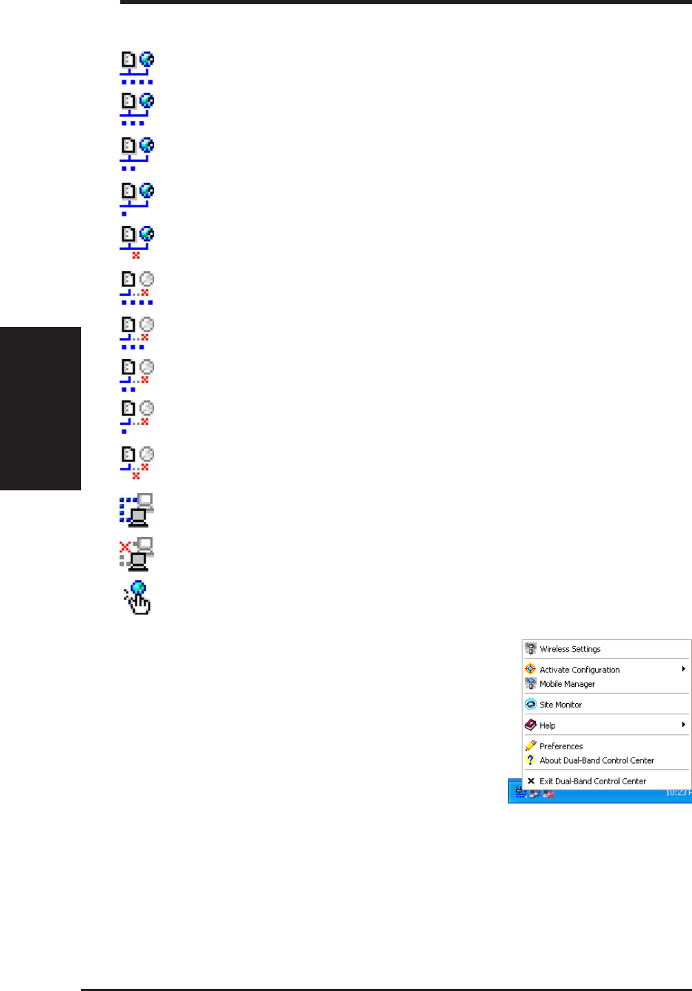
Wireless Status Icons (on the taskbar)
Excellent link quality and connected to Internet (Infrastructure)
Good link quality and connected to Internet (Infrastructure)
Fair link quality and connected to Internet (Infrastructure)
Poor link quality and connected to Internet (Infrastructure)
Not linked but connected to Internet (Infrastructure)
Excellent link quality but not connected to Internet (Infrastructure)
Good link quality but not connected to Internet (Infrastructure)
Fair link quality but not connected to Internet (Infrastructure)
Poor link quality but not connected to Internet (Infrastructure)
Not linked and not connected to Internet (Infrastructure)
Linked (Ad Hoc)
Not Linked (Ad Hoc)
Connected to Internet
Right-Click Menu
ASUS SpaceLink B&W PCI Card 23
Chapter 3 - Wireless LAN Reference
Chapter 3
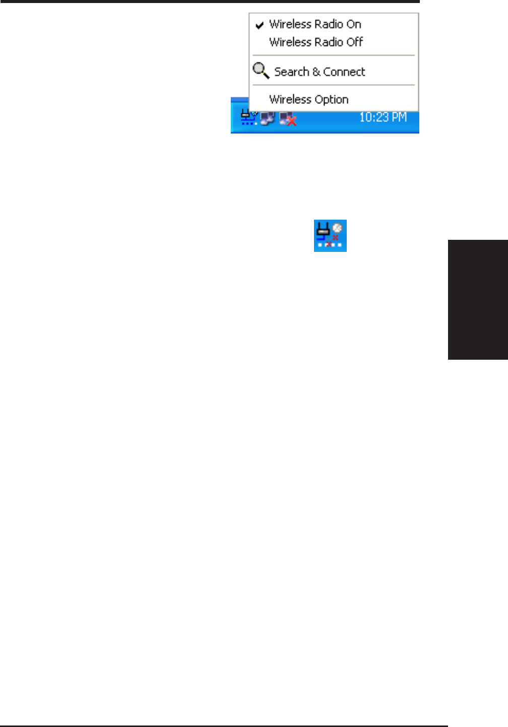
Left-clicking the taskbar icon shows
the following menu:
•Wireless Radio On – Turns the
wireless radio ON.
•Wireless Radio Off – Turns
the wireless radio OFF.
•Search & Connect – View the
properties of available Access
Points within range.
•Wireless Option (Windows XP only) – Sets your Windows XP wire-
less networking environment.
Double-clicking the taskbar icon:
• Launches the Wireless Settings application.
3.4 Wireless Settings
Wireless Settings is an application that allows you to control your ASUS
SpaceLink B&W PCI Card. Use Wireless Settings to View or Modify the
configuration settings and monitor the operational status of your PC Card.
Once Wireless Settings is launched, you can see the tabbed property sheet.
This property sheet is composed of tabbed “pages”, each with its own group
of feature-specific settings.
Starting Wireless Settings
• Open the Windows Control Panel, and then double-click the icon ASUS
DualBand WLAN Card Setting icon.
or
• Click the Windows Start button, select Programs, select ASUS
DualBand WLAN Card Utilities, and then click Wireless Settings.
or
• Click the Control Center icon on the Windows taskbar, a popup menu
appears, and then click Wireless Settings.
Taskbar Left-Click Menu
24 ASUS SpaceLink B&W PCI Card
Chapter 3 - Wireless LAN Reference
Chapter 3
More than one ASUS SpaceLink Card
If you have more than one ASUS SpaceLink Card. You will be given a
device selection window when you launch the “Wireless Settings” utility.
3.5 Status - Status Tab
You can view the information about the ASUS SpaceLink B&W PCI Card
from the general menu. These fields are blank if the ASUS SpaceLink B&W
PCI Card does not exist.
Scanning Connected

ASUS SpaceLink B&W PCI Card 25
Chapter 3 - Wireless LAN Reference
Chapter 3
Association State
Displays the connection status as follows:
Connected - The station is now associated with one wireless LAN device.
When operating in Infrastructure mode, this field shows the MAC address of
the Access Point with which you are communicating. When operating in Ad
Hoc mode, this field shows the virtual MAC address used by computers
participating in the Ad Hoc network.
Scanning... - The station is now attempting to authenticate and associate with
the desired Access Point or Ad Hoc node.
Disconnected - The link is connected, but no beacon received.
SSID
Displays the Service Set Identifier (SSID) that the card is either associated or
intending to join.
Network Type
Displays the type of the network that the card is in use. The value is either
"Infrastructure" or "Ad Hoc".
Current Channel
Displays the radio channel that the card is currently tuned. This number changes
as the radio scans the available channels.
MAC address
Indicates the hardware address of the card. MAC address is a unique identifier
for networking devices (typically written as twelve hexadecimal digits 0 through
9 and A through F, six hexadecimal numbers separated by colons, i.e.
00:E0:18:F0:05:C0).
Transmit Rate
Displays the current transmit data rate in megabits per second (Mbps).
Receive Rate
Displays the current receive data rate in megabits per second (Mbps).
26 ASUS SpaceLink B&W PCI Card
Chapter 3 - Wireless LAN Reference
Chapter 3
Security
Indicates whether or not Wired Equivalent Privacy (WEP) is enabled for the
station.
Power Save State
Shows the following indicating the power saving state of the station "Awake",
"Sleep Pending", "Sleep", "Fake Sleep Pending", "Faking Sleep", and
"Unknown".
Radio State
Shows the wireless radio on or off.
Radio On - When the wireless radio is turned off, the following
icon appears in the upper left of the Settings property page.
Radio Off - When the wireless radio is turned on, the following
icon appears in the upper left of the Settings property page.
Change SSID – Click on this to set the SSID.
Search & Connect – Click on this to connect to an available network.
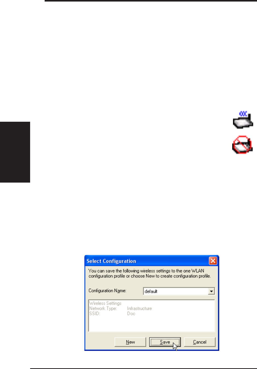
3.6 Save as Profile
Later, when you make individual settings, you may want to use profiles to
save your settings. Profiles will help you combine all your settings for
work, home, roaming, and other locations so that you do not have to repeat
individual settings.
ASUS SpaceLink B&W PCI Card 27
Chapter 3 - Wireless LAN Reference
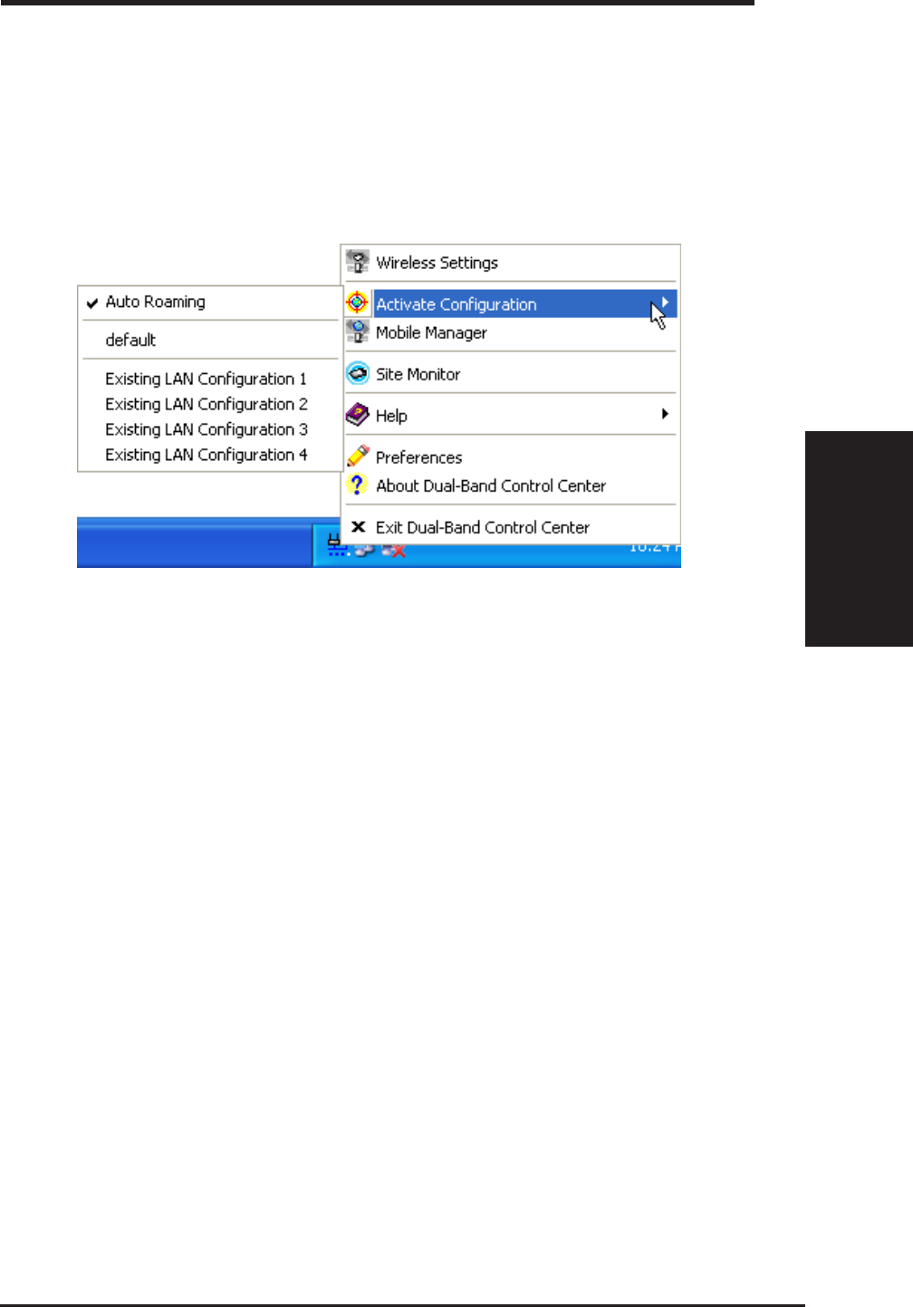
Chapter 3
3.7 Activate Configuration
Auto roaming is enabled by default and will automatically switch to stronger
access points. You can uncheck it if you have many access points and do
not want to constantly switch to different networks. If you want to use a
particular profile. You can also check it here.
28 ASUS SpaceLink B&W PCI Card
Chapter 3 - Wireless LAN Reference
Chapter 3
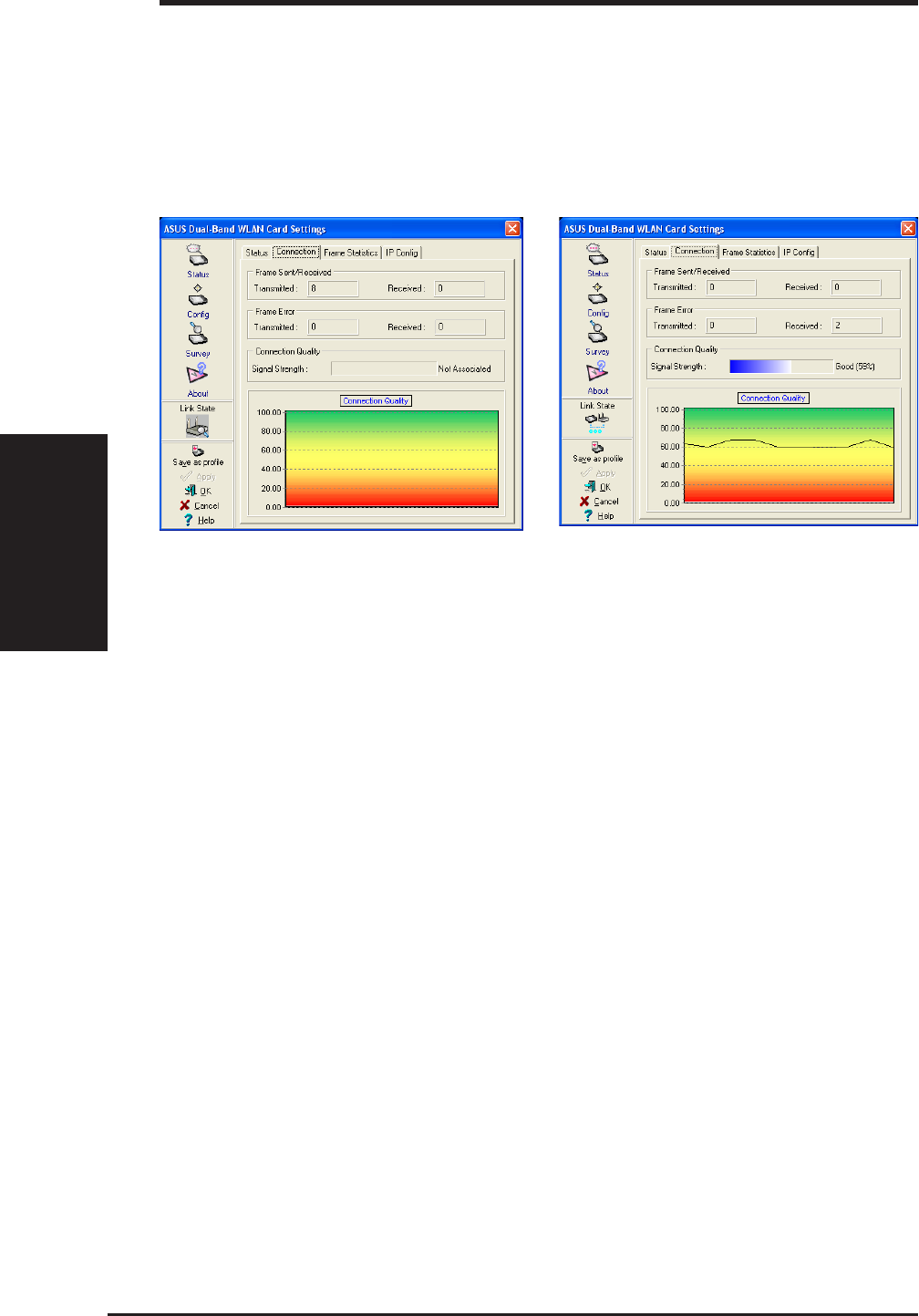
3.8 Status - Connection Tab
You can view the current link statistics about the ASUS SpaceLink B&W
PCI Card. These statistics are updated once per second and are valid only if
the ASUS SpaceLink B&W PCI Card exists.
Frame Sent/Received
Transmitted - The number of frames that were transmitted.
Received - The number of frames that were received.
Frame Error
Transmitted - The number of frames that were not successfully transmitted.
Received - The number of frames that were not successfully received.
Connection Quality
Signal Strength - Reflects the signal level related to the Access Point or Ad
Hoc node the station is currently connected to. Ratings are: Excellent, Good,
Fair, and Poor.
Overall Connection Quality
It is derived from the current "Signal Strength". A graph displays a connection
quality range between 0 and 100 percent.
Scanning Connected
ASUS SpaceLink B&W PCI Card 29
Chapter 3 - Wireless LAN Reference
Chapter 3
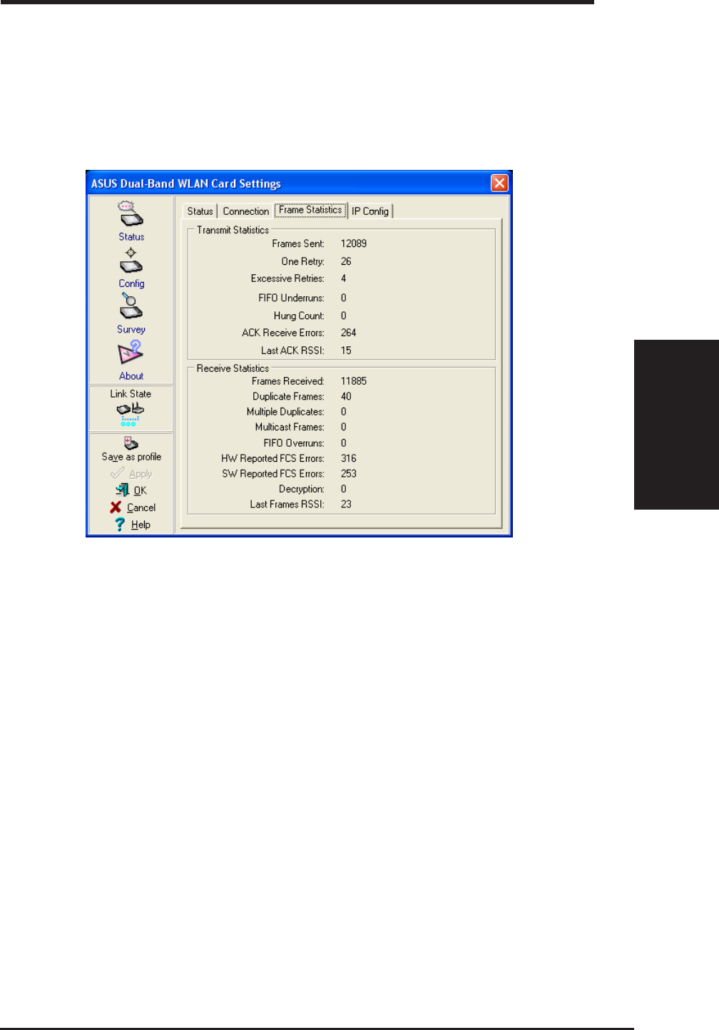
Frame Statistics
Frame statistics give information on data transferred though the wireless
LAN. You can monitor performance or trouble shoot signal quality within
different location of your wireless network.
Connected
30 ASUS SpaceLink B&W PCI Card
Chapter 3 - Wireless LAN Reference
Chapter 3
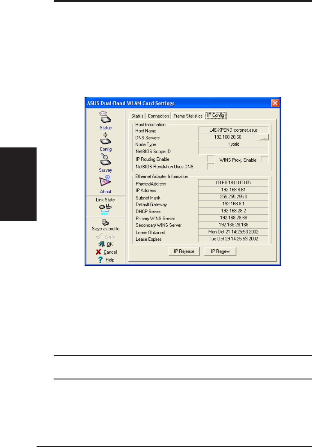
3.9 Status - IP Config Tab
IP Config tab shows all the current network configuration information for
the ASUS SpaceLink B&W PCI Card. Use it to verify your network settings.
IP CONFIG will display all the current TCP/IP configuration values
including the IP address, subnet mask, default gateway and Windows
Internet Naming Service (WINS) and DNS configuration.
Button
IP Release - Releases the DHCP IP address for the ASUS SpaceLink B&W
PCI Card.
IP Renew - Renews the DHCP IP address for the ASUS SpaceLink B&W
PCI Card.
NOTE: The IP Release and IP Renew buttons can only be used on
the ASUS SpaceLink B&W PCI Card that is configured with DHCP.
Connected
ASUS SpaceLink B&W PCI Card 31
Chapter 3 - Wireless LAN Reference
Chapter 3
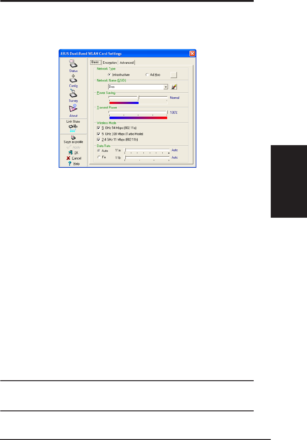
3.10 Config - Basic Tab
Lets you can change the ASUS SpaceLink B&W PCI Card configurations
without rebooting your computer.
Network Type
Infrastructure – Select the Infrastructure mode to establish a connec-
tion with an Access Point. Your computer is able to access wireless
LAN and wired LAN (Ethernet), via an associated access point. The
Channel field turns to “Auto” when “Infrastructure” is selected.
Ad Hoc – Select the “Ad Hoc” mode to communicate directly with
each other without using an Access Point. An “Ad Hoc” network is
typically formed quickly and easily without pre-planning. For example,
share meeting notes between networked computers in a meeting room.
SSID
Use the SSID filed to configure the SSID for the ASUS SpaceLink B&W
PCI Card. You can enter a new SSID or select one from the drop-down list
box. SSID stands for “Service Set Identifier”, which is a string used to identify
a wireless LAN. You will only be able to connect Access Points which has
the same SSID as the one you set. Use different SSIDs to segment the wireless
LAN and increase security. SSIDs must all be printable characters and having
a maximum of 32 case sensitive characters, such as “ Wireless LAN”.
Set the SSID to a null string, if you wish to allow your station to
connect to any Access Point it can find. But you cannot use null
string in Ad Hoc mode.
SSID Set to “Doc”

32 ASUS SpaceLink B&W PCI Card
Chapter 3 - Wireless LAN Reference
Chapter 3
Power Saving
This field allows the configuration of power management options to conserve
battery life. These options are "Off", "Normal, and "Maximum". Power
Management is disabled when "Ad Hoc" mode is selected in the Network
Type field.
When the Power Saving setting is Off, it allows a full powered state that yields
the best performance. This mode is recommended for devices running on AC
power.
Power Saving setting is Normal or Maximum will enable power savings
function, the adapter will wake up periodically to see if there is any data being
sent. This mode is recommended for devices running on battery power. The
difference is when the Power Saving setting is Normal, the driver turns off
power to the adapter for brief periods over briefly-spaced time intervals; when
the Power Saving setting is Maximum, the driver turns off power to the adapter
for long periods over widely-spaced time intervals.
Transmit Power
This field allows the configuration of transmit power options. The options are
"100%", "50%", "25%", "12.5", and "Lowest".
Wireless Mode
Choose which wireless mode the wireless card will use. You can enable more
than one wireless mode to allow system auto switch among them.
802.11a (5 GHz): Use this checkbox to allow the wireless card to use the 5
GHz and 54 Mbps wireless mode.
5 GHz 108 Mbps (Turbo Mode): Use this checkbox to allow the wireless
card to use the 5 GHz and 108 Mbps wireless mode. A high speed operating
mode for 802.11a radio space. Support data transfer speeds up to 108 Mbps,
twice the speed of standard 802.11a devices.
802.11b (2.4 GHz): Use this checkbox to allow the wireless card to use the 2.4
GHz and 11 Mbps wireless mode.
Click Apply to save and activate the new configurations.

ASUS SpaceLink B&W PCI Card 33
Chapter 3 - Wireless LAN Reference
Chapter 3
Data Rate
Select the transmit data rate (fix or auto). The data rates supported for the
ASUS SpaceLink WLAN Cards are:
Auto - The adapter will adjust to the most suitable transmission rate.
Fix - 11a: Fix data rate to 6, 9, 12, 18, 24, 36, 48, or 54 megabits per second.
11b: Fix data rate to 1, 2, 5, or 11 megabits per second.
Click Apply to save and activate the new configurations.
34 ASUS SpaceLink B&W PCI Card
Chapter 3 - Wireless LAN Reference
Chapter 3
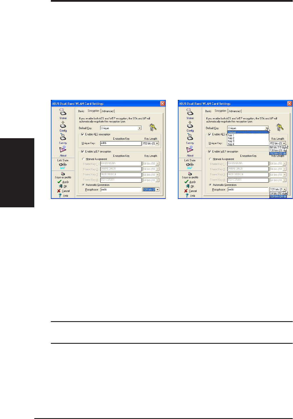
3.11 Encryption
Lets you configure the ASUS SpaceLink WLAN Card encryption settings. We
support two encryption types: Wired Equivalent Privacy (WEP) and Advanced
Encryption Security (AES). While WEP is universally supported and commonly
used, AES provides a much higher level of security. Frames encrypted with
AES are more difficult to decipher without known the key. Please note that
you will only be able to communicate with wireless devices that have use the
same encryption settings.
Pull Down Menus
WEP Enabled
Selecting Encryption Types (Enable AES or WEP)
Specify the encryption type AES or WEP. If you enable both, the STA and AP
will automatically negotiate the encryption type. By specifying auto, the STA
and AP will negotiate and attempt to use AES before exchanging data packets.
If the STA or AP does not support AES, WEP is used.
If one of the check boxes is selected, an encryption Key is used to encrypt your
data before it is transmitted over the air. If you enable encryption, you will only
be able to communicate with wireless devices that have use the same encryption
keys.
NOTE: AES is not supported in Ad Hoc mode, since Ad Hoc mode
does not support unique key.
Default Key
The Default Key field lets you specify which of the encryption key (Unique,
First, Second, Third, or Fourth) you use to transmit data on your wireless LAN.
You can change the default key by clicking on the down arrow at the right of

ASUS SpaceLink B&W PCI Card 35
Chapter 3 - Wireless LAN Reference
Chapter 3
this field, selecting the number of the key you want to use and then clicking the
Apply button. As long as the Access Point or station with which you are
communicating has the same key in the same position, you can use any of the
keys as the default.
Key Length
Defines the length for each encryption key. As the Key Length is changed, the
number of available characters in the filed is changed automatically. For 64
bits encryption, each Key contains exactly 10 hexadecimal digits. For 128 bits
encryption, each Key contains exactly 26 hexadecimal digits. For 152 bits
encryption, each Key contains exactly 32 hexadecimal digits.
Unique Key
This option is enable only if you enable AES Encryption. Defines the unique
encryption key for security for the current network configuration. In Ad Hoc
mode, this encryption key type is not used.
Shared Key
This option is enable only if you enable WEP Encryption. The WEP Key is a
64 bits (5 byte), 128 bits (13 byte) or 152 bits (16 byte) Hexadecimal digits that
is used to encrypt transmit data packets and decrypt received data packets.
Two ways to assign Shared Keys
Manual Assignment - When you click this button, the cursor appears in the
field for Key 1. To enable WEP encryption, you are required to enter at least
one shared key. For 64-bit encryption, each Key contains exactly 10 hex digits
(0~9, a~f, and A~F). For 128-bit encryption, each Key contains exactly 26 hex
digits (0~9, a~f, and A~F). For 152-bit encryption, each Key contains exactly
32 hex digits (0~9, a~f, and A~F).
Automatic Generation - Type a combination of up to 64 letters, numbers, or
symbols in the Passphrase column, then the Wireless Settings Utility uses an
algorithm to generate four shared Keys for encryption.
NOTE: This function ease users from having to remember their
passwords and is compatible to some existing WLAN utilities, but
it is not very secure. "Manual Assignment" is more secure.
NOTE: Click the Apply or OK button to save the encryption set-
tings. The keys you entered will be masked by asterisks.

36 ASUS SpaceLink B&W PCI Card
Chapter 3 - Wireless LAN Reference
Chapter 3
64/128bits versus 40/104bits
You may be confused about configuring WEP encryption, especially when
using multiple wireless LAN products from different vendors. There are
two levels of WEP Encryption: 64 bits and 128 bits.
First, 64 bit WEP and 40 bit WEP are the same encryption method and can
interoperate in the wireless network. This lower level of WEP encryption
uses a 40 bit (10 Hex character) as a “secret key” (set by user), and a 24 bit
“Initialization Vector” (not under user control). This together makes 64
bits (40 + 24). Some vendors refer to this level of WEP as 40 bits and
others refer to this as 64 bits. ASUS SpaceLink products use the term 64
bits when referring to this lower level of encryption.
Second, 104 bit WEP and 128 bit WEP are the same encryption method
and can interoperate in the wireless network. This higher level of WEP
encryption uses a 104 bit (26 Hex character) as a “secret key” (set by user),
and a 24 bit “Initialization Vector” (not under user control). This together
makes 128 bits (104 + 24). Some vendors refer to this level of WEP as 104
bits and others refer to this as 128 bits. ASUS SpaceLink products use the
term 128 bits when referring to this higher level of encryption.
Click Apply to save and activate the new configurations.
ASUS SpaceLink B&W PCI Card 37
Chapter 3 - Wireless LAN Reference
Chapter 3
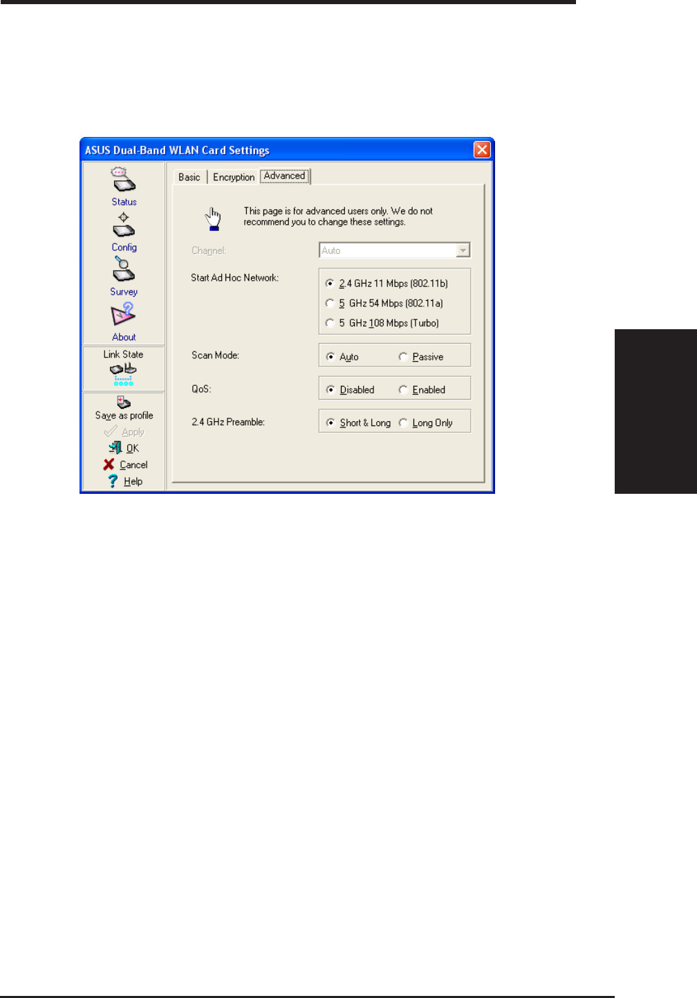
3.12 Config - Advanced Tab
Advanced tab provides some additional settings for the ASUS SpaceLink
B&W PCI Card.
Channel
Using the Channel field to select the radio channel for card. In an "infrastructure"
network, the card will automatically select the correct frequency channel
required to communicate with an Access Point, this parameter will be fixed in
"Auto" and cannot be changed. In an "Ad Hoc" network, you can decide channel
number for the card. The radio channels you may use depend on the regulations
in your country.
Start Ad Hoc Network
Choose which wireless mode will start an Ad Hoc network if no matching
SSID is found after scanning all available modes. The default value is 5 GHz
54 Mbps (802.11a).
Scan Mode
Allows selection of the wireless card scanning method used to locate access

38 ASUS SpaceLink B&W PCI Card
Chapter 3 - Wireless LAN Reference
Chapter 3
Click Apply to save and activate the new configurations.
points or ad hoc networks. The default value is Auto.
Passive: Click on this radio button to specify passive scanning. Passive scanning
indicates that the wireless card is in listen-only mode.
Auto: Click on this radio button to specify automatic scanning. The driver
uses the country code to determine which type of scanning to use, either active
or passive.
QoS
Specifies disable or enable the station to cooperate in a network using Quality
of Service (QoS).
2.4 GHz Preamble
Specifies Short & Long or Long-Only preamble mode for a 2.4 GHz/11 Mb
network. Long-Only is used for backward-compatibility with older 2.4 GHz
devices. The default value is Short & Long.
ASUS SpaceLink B&W PCI Card 39
Chapter 3 - Wireless LAN Reference
Chapter 3
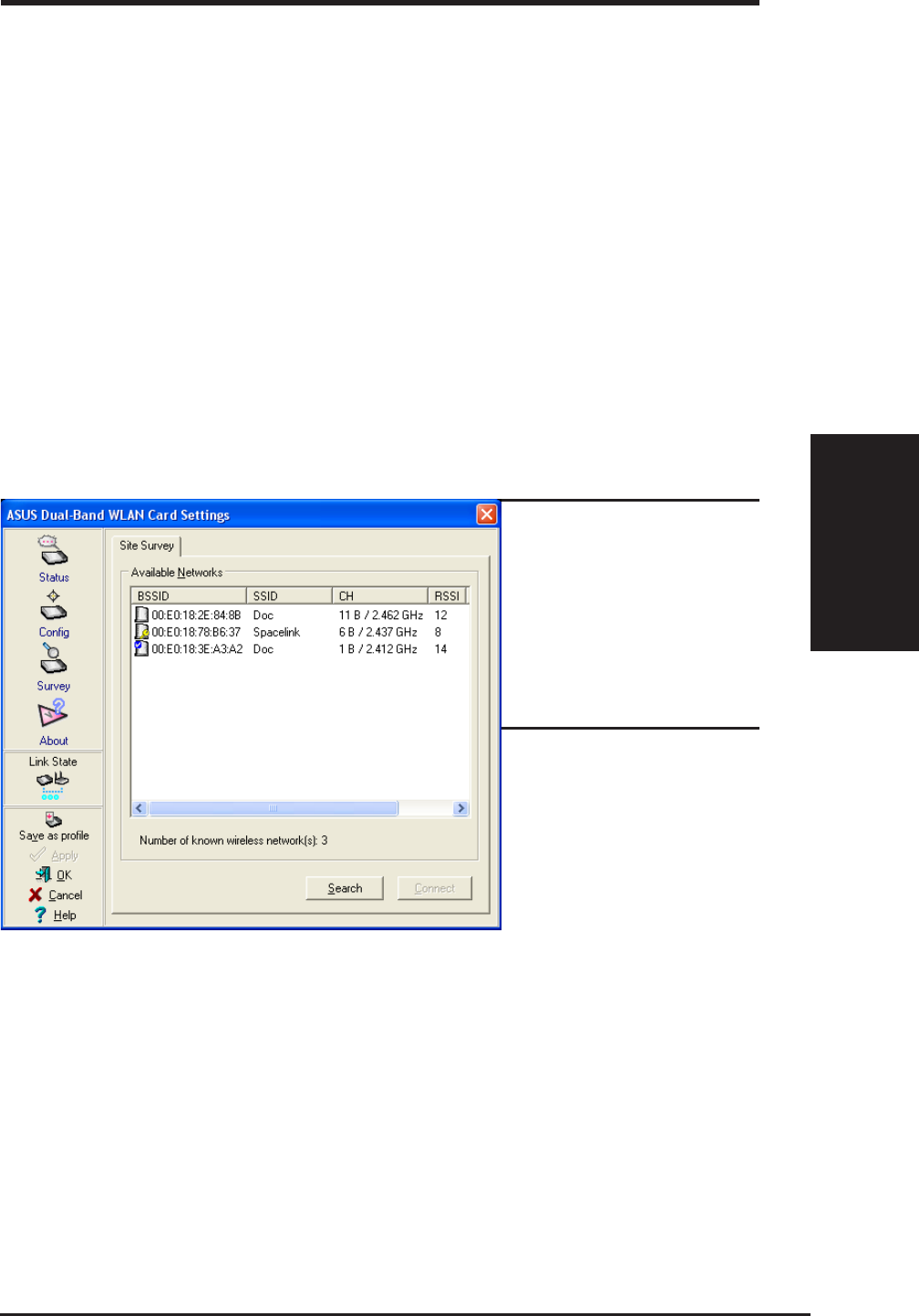
3.13 Survey - Site Survey Tab
Use the Site Survey tab to view statistics on the wireless networks available
to the ASUS SpaceLink B&W PCI Card. The Site Survey tab is read-only
with no user configurable data fields. Use the Site Survey tab to view the
following network parameters.
•BSSID – View the IEEE MAC addresses of the available networks.
•SSID – View the SSID (service set identification) within available networks.
•CH – View the direct-sequence channel used by each network.
•RSSI – Views the Received Signal Strength Indication (RSSI) in dB.
•Type – View wireless network status information, the value is either
AP (infrastructure) or STA (Ad Hoc).
•WEP – View wireless network WEP encryption information, the value
is either OFF (disable encryption) or ON (enable encryption).
Buttons
Search – Scan all available wireless networks and show the scan result in
the “Available Network List”.
Connect – To associate a network, select it from the “Available Network
List” and click this button.
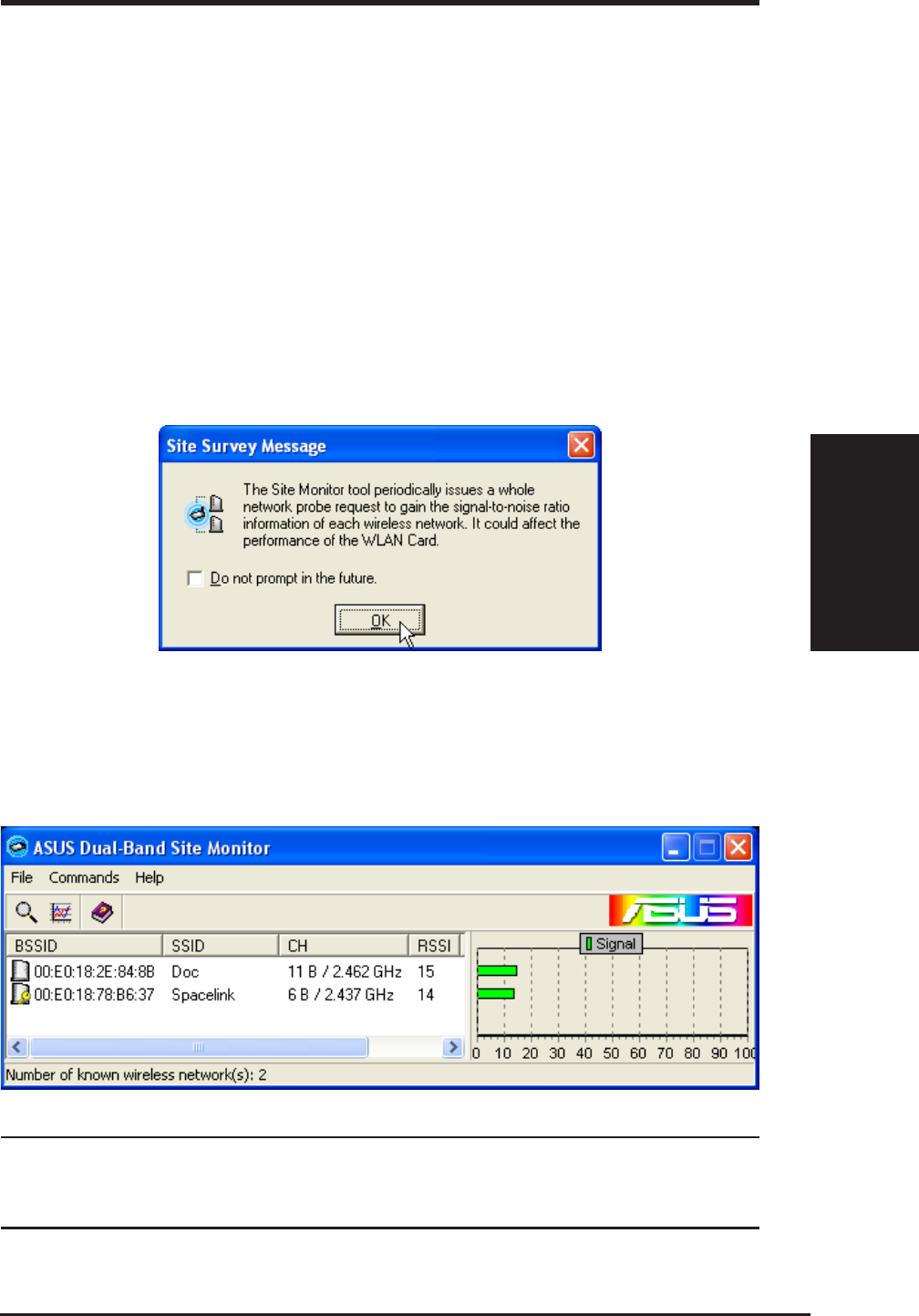
Some Access Points
can disable broadcast-
ing SSID to hide them-
selves from “Site Sur-
vey” or “Site Monitor”
for added security but
still allow you to join if
you know their SSID.
40 ASUS SpaceLink B&W PCI Card
Chapter 3 - Wireless LAN Reference
Chapter 3
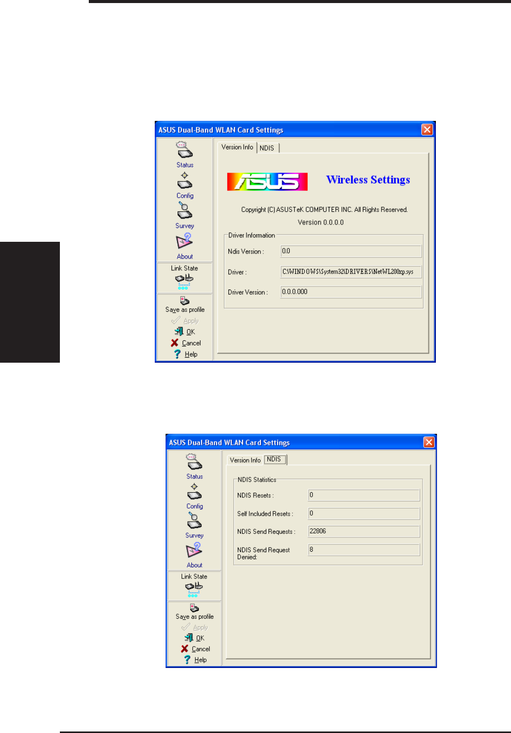
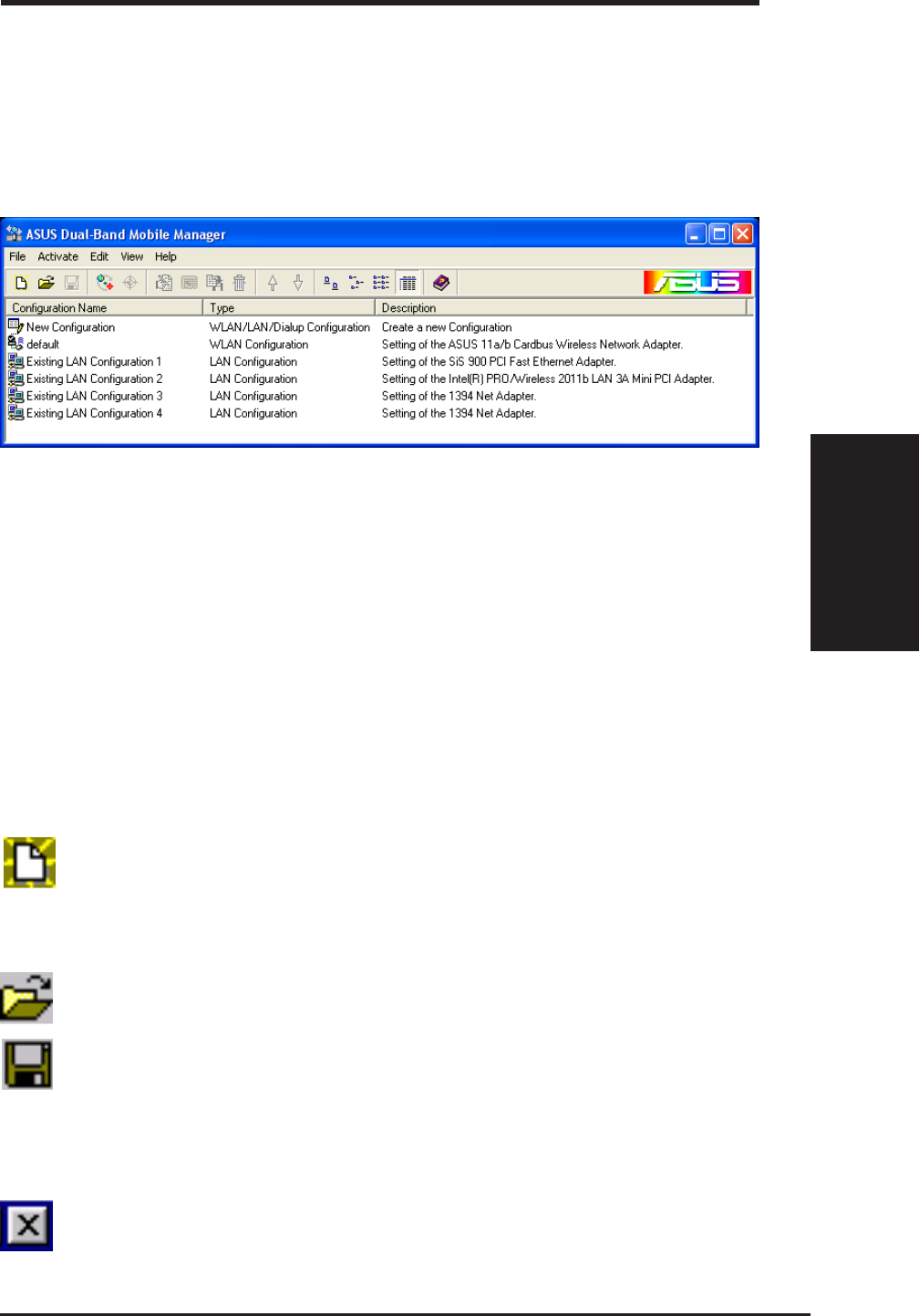
3.14 About - Version Info Tab
Uses the Version Info tab to view program and ASUS SpaceLink WLAN
Card version information. The program version information field includes
the Copyright and utility version. The version information includes the
ndis version, driver name, and driver version.
Network Driver Interface Specification
This screen is an example only. Normally,
you will see non-zero version numbers.

ASUS SpaceLink B&W PCI Card 41
Chapter 3 - Wireless LAN Reference
Chapter 3
To Exit Wireless Settings
To exit Wireless Settings, you can click OK or Cancel. This utility may be
closed at any time and from any tab. If you did not save the configuration
settings, you will be prompted to do so.
3.15 Link Status
ASUS SpaceLink B&W PCI Card connection quality icon appears on the
left of the ASUS WLAN Card Settings. Use the icon to view the current
signal quality of the adapter.
Excellent Link Quality (Infrastructure)
Good Link Quality (Infrastructure)
Fair Link Quality (Infrastructure)
Poor Link Quality (Infrastructure)
Not linked (Infrastructure)
Linked (Ad Hoc)
Not Linked (Ad Hoc)

42 ASUS SpaceLink B&W PCI Card
Chapter 3 - Wireless LAN Reference
Chapter 3
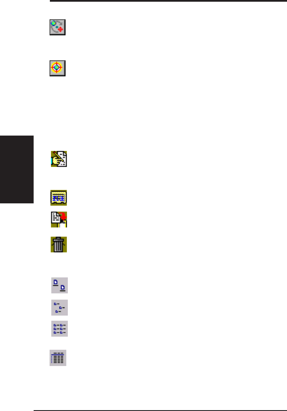
3.16 Mobile Manager
Mobile Manager is a convenient tool to setup and manage network location
settings. Mobile Manager lets users configure multiple alternative
configurations for different locations. You only need to set this once, and
then easily switch configurations when you change your location.
Starting Mobile Manager
• Click the Windows Start button, select Programs, select ASUS Dual-
Band WLAN Card Utilities, and then click Mobile Manager.
or
• Right-click the Control Center icon on the Windows taskbar and then
click Mobile Manager.
Using Mobile Manager - Quick Guide
1. The first time you launch the Mobile Manager utility, it will automati-
cally generate configurations that stores the current settings of all in-
stalled network devices in your system.
2. Change the name of the configuration to a descriptive name like “Work-
Meeting Room” or “Home-ADSL”.
3. On the File menu, click New Configuration, the New Configuration
Wizard dialog appears. Follow the on-screen instructions to create your
own location configurations.
4. After you have created your configurations, you can see them in the
main window.
5. Select the configuration you want to use and then click Activate Con-
figuration from the Activate pull-down menu. Your system will then
switch to the network settings configured to your chosen selection.
ASUS SpaceLink B&W PCI Card 43
Chapter 3 - Wireless LAN Reference
Chapter 3
Main Window
You can use the Mobile Manager utility main window to create a new
configuration, edit a configuration or activate a configuration. The main window
includes a menu bar, tool bar, and a list view for showing existing configurations.
Using the pull-down menu and toolbar
The following topics show the commands available from the Mobile Manager
pull-down menu and toolbar. If no configuration is selected, some commands
will be grayed out and inaccessible. The toolbar contains buttons for many of
the most commonly used commands in Mobile Manager. It allows quick access
to some of the most useful features of Mobile Manager. The commands provided
by the toolbar buttons are also available from the pull-down menu.
File Menu
New Configuration - Select New Configuration in the File menu
to open a New Configuration Wizard dialog. Use the New Configu-
ration Wizard dialog to create a new configuration. See Using New
Configuration Wizard for details on this command.
Import Configuration - Load a configuration from an INI File.
Export Configuration - Save the selected configuration (contain-
ing Wireless Settings, TCP/IP Settings, Network Settings, ...) to an
INI File. The INI file can be placed on a floppy diskette and then
imported by other computers using Mobile Manager. This can also
be used as a backup feature for yourself.
Exit - Close the Mobile Manager utility.
44 ASUS SpaceLink B&W PCI Card
Chapter 3 - Wireless LAN Reference
Chapter 3
Mobilize Menu
Auto Roaming – If an association changes, it will automatically
switch into a network configuration that you have made. If no asso-
ciations have been made, it will automatically connect to a wireless
network based on configurations that you specify.
Activate Configuration – Applies the configuration that you have
selected from the list. You may be prompted to restart Windows
depending on the required changes. Follow the instructions on the
screen. Windows 2000 and XP usually do not require restarting your
computer, but Windows 98 and ME usually will require a restart.
Edit Menu
All these commands are also available from the context menu that appears
when you right-click with a configuration in the Mobile Manager window.
Edit Configuration - Select Edit Configuration in the Edit menu to
open an Edit Configuration dialog to edit selected configuration
items. See “Using Edit Configuration” for details on this command.
Rename - Change the name of the selected configuration.
Copy - Duplicate the selected configuration.
Delete - Discard the selected configuration.
View Menu
Large Icons - Displays large icons for each configuration.
Small Icons - Displays small icons for each configuration.
List - Shows the configuration names in a list.
Details - The Detailed view expands this list to include information
about the configurations. The information includes configuration
name, type, and description.

ASUS SpaceLink B&W PCI Card 45
Chapter 3 - Wireless LAN Reference
Chapter 3
Help Menu
Contents - Displays the WinHelp contents window (the one you
are reading now) for online Help.
About Mobile Manager - Displays the version number and copy-
right information for Mobile Manager. Click on the logo to connect
to ASUS’ website.
46 ASUS SpaceLink B&W PCI Card
Chapter 3 - Wireless LAN Reference
Chapter 3
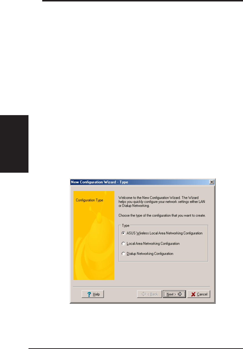
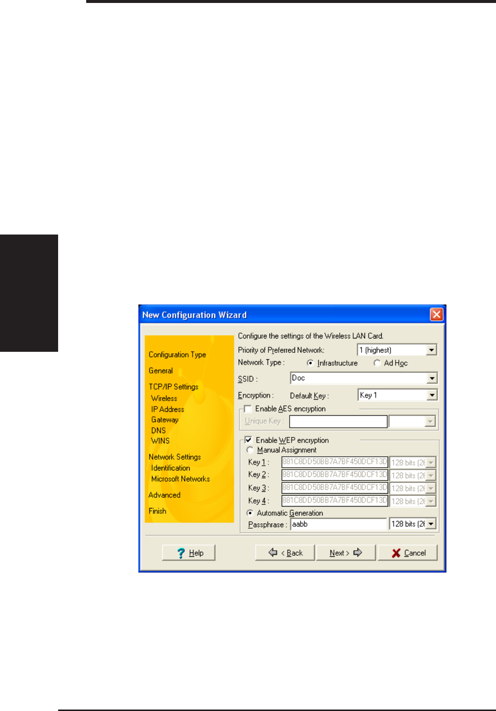
Using New Configuration Wizard
Create a new configuration
Create a new configuration if you are in a specific location that does not
have an existing configuration defined. Use the New Configuration Wizard
to create a configuration in a few easy steps.
1. Do one of the following:
• On the File menu, click New Configuration.
or
• Double-click New Configuration on the Main window.
Then the New Configuration Wizard dialog starts.
2. Choose the type of configuration that you want to create and click Next.
•Wireless Local Area Network Configuration: You must have an
ASUS SpaceLink B&W PCI Card installed in your PC.
•Wired Local Area Network Configuration: You must have a NIC (LAN
card) (other than ASUS SpaceLink B&W PCI Card) installed in your
PC.
•Dialup Networking Configuration: You must have a modem in-
stalled in your PC.

ASUS SpaceLink B&W PCI Card 47
Chapter 3 - Wireless LAN Reference
Chapter 3
3. Enter the name and description you want to use for this configuration
in the Name and description field. And Click Next.
4. Follow the on-screen instructions, it will guide you through the process
of specifying the settings in your configuration. The Wizard reads the
current system settings (TCP/IP, NT Domain, Proxy, File, and Printer
Sharing) and displays it. Depending on the configuration that you have
created, you can set the following groups of settings:
• Wireless settings (for Wireless Configuration)
• Network settings (for Wireless/Wired Configuration)
• TCP/IP settings (for Wireless/Wired Configuration)
• Dialing settings (for Dialup Configuration)
• Dialup Networking settings (for Dialup Configuration)
• Internet settings (for Wireless/Wired/Dialup Configuration)
• Sharing settings (for Wireless/Wired/Dialup Configuration)
See “Using Edit Configuration” for detailed information on each.
5. Enter the appropriate information in the wizard. After specifying the
appropriate information on each page, click Next to continue.
6. On the final window of the New Configuration Wizard, you will see a
Finish button.
• If you do not want to use this new configuration now, click Finish
to save the new configuration. It will be shown in the Mobile Man-
ager main window.
or
• If you want to use this new configuration now, click Mobilize.
Using Edit Configuration
Edit an existing configuration
Edit a configuration if you want to view or change dialup or LAN settings.
• On the Edit menu, click Edit Configuration.
or
• Double-click one existing configuration on the Main window.
Then the Edit Configuration dialog starts.
The Edit Configuration dialog contains various settings, which you select by
clicking the buttons at the left of the window. Each setting is described below.

48 ASUS SpaceLink B&W PCI Card
Chapter 3 - Wireless LAN Reference
Chapter 3
General settings
Name – This field is mandatory, and used for indicating the location
from which you are dialing or connecting to the network. For example,
if this is used for a meeting room at work, you can use a name like
“Work-Meeting Room”. If it is used for home on your ADSL, you can
name like “Home-ADSL”.
Description – This field is optional, you can use it to provide more
details about this configuration.
Network settings
Network settings include: “Identification” and “Microsoft Networking”.
Identification
Computer name – Give your computer a unique name of up to 15
characters. Thecomputer name is the name that others on your net-
work will see your computer as. For complete compatibility, do not use
spaces or symbols. It’s generally the same as the DNS hostname, for
example, “JohnDoe”.
Workgroup – Type an existing workgroup name or create a new
workgroup by typing a new name that contains up to 15 characters. Use
it to identify your computer group that you belong to.
Computer Description – This information is displayed as a comment
next to the computer name when the computer is seen in “Details” view
(select from the Windows pull-down menu). Use it to describe your
computer, for example, your name, or location.
Microsoft Networking
Logon validation – Specify how Windows 9x clients connect to a Win-
dows NT Server Domain at this location.Check Log on to Windows NT
domain box if you are using a Windows NT Server in domain control-
ler mode. And then enter the Window NT server domain name in Win-
dow NT domain field.
Network logon options – Specify how Windows 9x clients try to logon.
Select Quick logon to wait until the shared network drives is actually
used to attempt the login. Select Logon and restore network connections
to logon to all shared network drives when the user logs into Windows.

ASUS SpaceLink B&W PCI Card 49
Chapter 3 - Wireless LAN Reference
Chapter 3
Wireless settings
Network Type
Infrastructure – Select the Infrastructure mode to establish a connec-
tion with an Access Point.
Ad Hoc – Select the Ad Hoc mode to communicate directly with each
other without using an Access Point.
SSID
Using the SSID filed to configure the SSID setting for the ASUS SpaceLink
B&W PCI Card. SSID stands for Service Set Identifier, which is a string
used to identify a wireless LAN. You will only be able to connect with an
Access Point, which has the same SSID. Use different SSIDs to segment
the wireless LAN and add security.
Note that the SSID must be all printable character string (case sensitivity)
and up to 32 characters long, such as “ WIRELESS LAN”. Set the SSID to
a null string, if you wish to allow your station to connect to any Access
Point it can find. But you cannot use null string in Ad Hoc mode.
Encryption
Select disable or enable AES or WEP encryption. If you enable both, the
STA and AP will automatically negotiate the encryption type. By specifying
auto, the STA and AP will negotiate and attempt to use AES before
exchanging data packets. If the STA or AP does not support AES, WEP is
used.
If one of the check boxes is selected, an encryption Key is used to encrypt
your data before it is transmitted over the air. If you enable encryption, you
will only be able to communicate with wireless devices that have use the
same encryption keys.
NOTE: AES is not supported in Ad Hoc mode, since Ad Hoc mode
does not support unique key.
50 ASUS SpaceLink B&W PCI Card
Chapter 3 - Wireless LAN Reference
Chapter 3
TCP/IP settings
TCP/IP settings include five tabs: Device, IP Address, Gateway, DNS, and
WINS.
Device
Choose the network adapter that you want to use for this configuration.
IP Address
Obtain an IP address from a DHCP server – Dynamic host configu-
ration protocol (DHCP) server assigns IP addresses automatically within
a specified range to devices.
Specify an IP address – Ask your network administrator for the IP
address and subnet mask that you should use. Type in the IP Address
and Subnet Mask fields manually.

ASUS SpaceLink B&W PCI Card 51
Chapter 3 - Wireless LAN Reference
Chapter 3
Gateway
Specify the gateways. There can be more than one specified.Set up the
primary gateway first.
Add a gateway - Type the IP address of the gateway in the New Gate-
way field and then click Add. The gateway you specified appears in the
Installed Gateways list. Repeat to specify another gateways. The value
in each field must be a number between 0 and 255. You can have up to
eight IP addresses for gateways.
Remove a gateway - Select the gateway from the Installed Gateways
list and click Remove.
DNS
Select Enable or Disable DNS. If you enable DNS, fill the following
parameters.
Host – Enter the name of your computer. That is used to identifier the
computer on the Internet. The hostname is generally the same as the
Microsoft networking computer name, for example, “S82000W”.
Domain – Enter the TCP/IP domain name for your network.The full
domain name consists of one or more names that are separated by dots,
for example, “asus.com”.
DNS Server Search Order – Specify the DNS Servers in the desired
order to search for DNS information.
Domain Suffix Search Order – Add any domain suffixes that may be
valid attached to the end of Internet domain name.
WINS
Specify the WINS server. There can be more than one specified.Set up the
primary WINS server first.
Disable WINS Resolution – Do not use WINS resolution.
Enable WINS Resolution – Use WINS resolution. Specify the IP ad-
dresses of the WINS servers in the desired search order. Scope ID is
used when NetBIOS over TCP/IP is enabling on the workstations. If
this protocol has been enabled, then every workstation group must have
the same Scope ID for those computers to communicate within the group.
The Scope ID is usually left blank.
Use DHCP for WINS Resolution – If a DHCP server is available that
is configured to provide information on available WINS servers.

52 ASUS SpaceLink B&W PCI Card
Chapter 3 - Wireless LAN Reference
Chapter 3
Dialing settings
Specify how the call will be dialed. This is useful if you want to change the
call to a calling card, use your computer from different locations, or add a
dial prefix, country code, or area code automatically.
Dialup Networking settings
Dialup Networking settings include four tabs: Device, Phone Number,
Server Type, and TCP/IP.
Device
Choose the modem you want to use by Dial-Up Networking to connect to
another computer for this connection.
Phone Number
Specify area code, telephone number, and country code for this connection.
Clear the Use area code and Dialing Properties checkbox, if you want to
ignore area code and dialing settings.
Server Type
Type of Dial-Up Server – Select the server type for this connection.
Advanced options
Select Log on to network checkbox to specify that Dial-Up Networking
will attempt to log on to the network you are connecting to, using the user
name and password you typed when you logged on to Windows.
Select Enable software compression checkbox to specify whether
incoming or outgoing information is compressed before it is sent. This is
useful to speed up the transfer of information. Compression occurs only if
both computers are using compatible compression.

ASUS SpaceLink B&W PCI Card 53
Chapter 3 - Wireless LAN Reference
Chapter 3
Select Require encrypted password checkbox to specify that only
encrypted passwords can be sent to or accepted by your computer. This is
useful if you need additional security for this connection. When type your
password while dialing out, this setting will encrypt your password but the
target computer must support encrypted passwords for your password to
be understood.
Allowed network protocols – Specifies the network protocols that your
computer can use.
Select NetBEUI protocol to connect to Windows NT, Windows for
Workgroups, or LAN Manager servers.
Select IPX/SPX Compatible protocol to connect to Netware and Win-
dows NT servers and Windows 98 computers.
Select TCP/IP protocol to connect to Internet and wide-area networks.
TCP/IP
Server assigned IP address – Specifies whether Dialup Networking
accepts an IP address from a ppp server. If the ppp server does not offer
an IP address, the IP address specified for TCP/IP Dial-Up Adapter in
the Network dialog box is used.
Specify an IP address – Provides a space for you to type the preferred
IP address for this connection. Dial-Up Networking tries to use this
address first.
Server assigned name server addresses – Specifies whether Dial-Up
Networking accepts a DNS and WINS server addresses from a ppp
server. If the ppp server does not offer DNS and WINS addresses, DNS
and WINS server addresses specified for TCP/IP Dial-Up Adapter in
the Network dialog box are used.
Specify name server addresses – Provides a space for you to type one
or two DNS and WINS server addresses for this connection only. Dial-
Up Networking tries to use these addresses first.
Use IP header compression – Specifies whether Dial-Up Networking
uses IP header compression for this connection. IP header compression
optimizes data transfer between computers.
Use default gateway on remote network – Specifies whether IP traf-
fic is routed to the WAN connection by default.

54 ASUS SpaceLink B&W PCI Card
Chapter 3 - Wireless LAN Reference
Chapter 3
Internet settings
A proxy server acts as a security barrier between your internal network
(Intranet) and the Internet, keeping other people on the Internet from gaining
access to confidential information on your internal network or your
computer.
Disable Proxy Server – Do not use proxy server.
Enable Proxy Server – Use the Proxy server to gain access to the Internet.
Use the same proxy server for all protocols – Specifies whether you
want to use the same proxy server to gain access to the Internet using
all protocols.
Servers – Provides spaces for you to type the address and port number
of the proxy server you want to use to gain access to the Internet over
HTTP, Secure, FTP, Gopher, and Socks protocol.
Exceptions
Do not use proxy server for address beginning with – Provides a space
for you to type the Web addresses that do not need to be accessed through
the proxy server. If you want to connect to a computer on your Intranet,
make sure you type its address in this box. You can use wild cards to match
domain and host names or addresses, for example, “*.company.com”,
“192.72.111.*”.
Bypass proxy server for local addresses – Specifies whether you want to
use the proxy server for all local (Intranet) addresses. You might be able to
gain access to local addresses easier and faster if you do not use the proxy
server.
Sharing settings
I want to be able to give others access to my files – Turn file sharing ON
or OFF. File sharing enables people using other computers to read or modify
files you share on your computer.
I want to be able to allow others to print to my printer(s) – Turn printer
sharing ON or OFF. Printer sharing enables people using other computers
to printer their files on your printers.
Click Save button to save all the changes you have made without clos-
ing the Edit Configuration dialog box.
Click Cancel button to close the Edit Configuration dialog box without
saving any changes you have made.
Click Close button to close the Edit Configuration dialog box and save
any changes that you have made.
ASUS SpaceLink B&W PCI Card 55
Chapter 3 - Wireless LAN Reference
Chapter 3
Site Monitor
Site Monitor measures the received signal strength indicator (RSSI) values
of all available wireless networks. This tool is used for determining the
best placement of Access Points to provide the best coverage for a wireless
network.
Starting Site Monitor
• Click the Windows Start button, select Programs, select ASUS Dual-
Band WLAN Card Utilities, and then click Site Monitor.
or
• Right-click the Control Center icon on the Windows taskbar and then
click Site Monitor.
Main Screen
Measures the signal-to-noise (SNR) values of all available wireless
networks.
Some Access Points can disable broadcasting SSID to hide them-
selves from “Site Survey” or “Site Monitor” for added security
but still allow you to join if you know their SSID.
56 ASUS SpaceLink B&W PCI Card
Chapter 3 - Wireless LAN Reference
Chapter 3
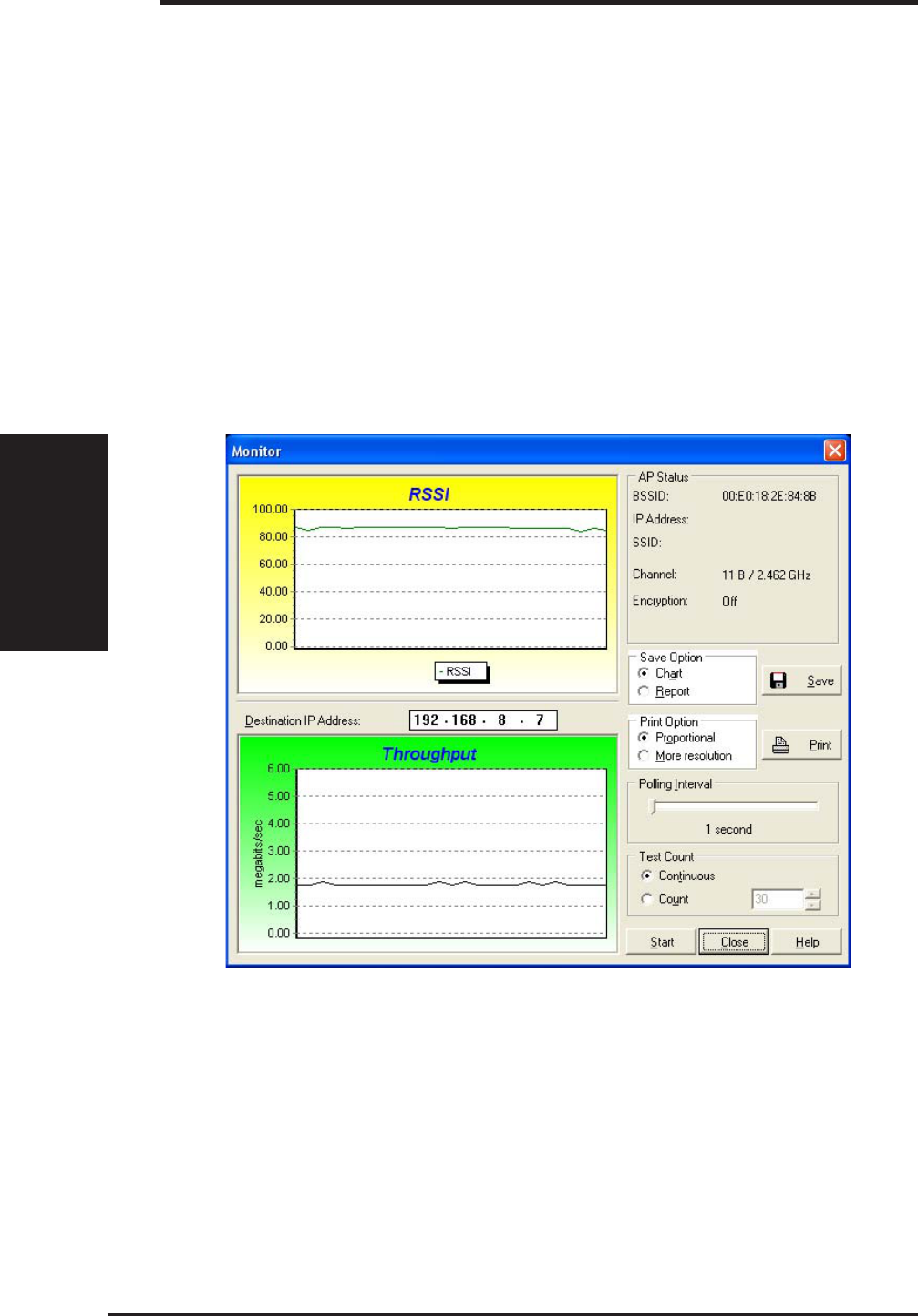
Monitor
Directed link state test with one particular wireless network, including:
RSSI: This indicates the value of received signal strength of the last received
frame. In principle, the higher the RSSI, the better your communications
quality.
Throughput: This sends a specified number of data packets to the remote
host and calculates the average megabytes per second.
During the test, the Start button toggles to Stop. You can click Start button
to begin the link test and click Stop button at any time to terminate the test.
ASUS SpaceLink B&W PCI Card 57
Chapter 3 - Wireless LAN Reference
Chapter 3
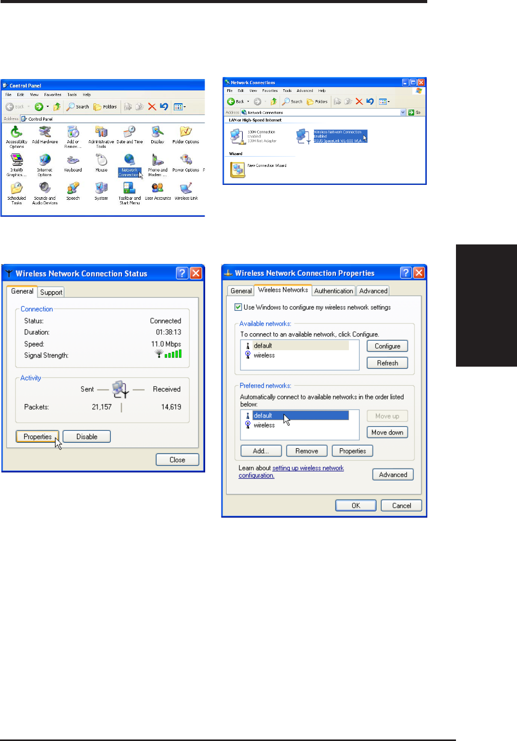
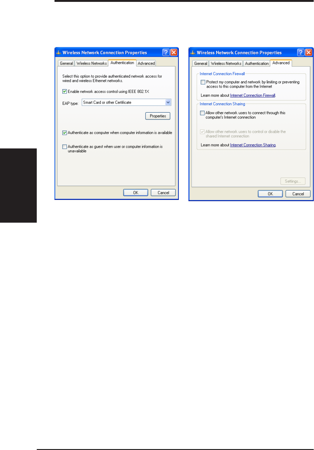
3.17 Windows XP Wireless Properties
2. Double-click ASUS SpaceLink WL230...
1. Double-click System icon in the Control Panel.
3. The “General” page will show status,
duration, speed, and signal strength. Signal
strength is represented by green bars with
5 bars meaning excellent signal and 1 bar
meaning poor signal.
4. The “Wireless Networks” page will show
Available networks and Preferred networks.
Use the Add button to add the “SSID” of
available networks and set the connection
preference order with the Move up and
Move down buttons. The radio tower with
a signal icon identifies the currently
connected access point.
58 ASUS SpaceLink B&W PCI Card
Chapter 3 - Wireless LAN Reference
Chapter 3
5. The “Authentication” page allows you to add
security settings. Read Windows help for
more information.
6. The “Advanced” page allows you to set
firewall and sharing. Read Windows help
for more information.
3.7 Windows XP Wireless Properties (Cont.)

ASUS SpaceLink B&W PCI Card 59
Chapter 4 - Bluetooth Reference
Chapter 4
Bluetooth Reference
Introduction to Bluetooth
The term "Bluetooth" refers to a worldwide standard for the wireless exchange
of data between two devices.
In order to exchange data, two Bluetooth devices must establish a connection.
Before a connection is established, one device must request a connection with
another. The second device accepts (or rejects) the connection. The originator
of the request is known as the client. The device that accepts (or rejects) the
request is known as the server. Many Bluetooth devices can act as both client
and server.
A client Bluetooth device runs a software program that requests a connection
to another device as part of its normal operation. For example, the program
may request a connection to a remote computer, a printer, PDA, or a Cellular
Phone. Becoming a Bluetooth client normally requires an action by the device
operator, such as an attempt to browse a remote computer, print a file, or dial
out on a Cellular Phone.
Every Bluetooth device that provides a service must be prepared to respond to
a connection request. Bluetooth software is always running in the background
on the server, ready to respond to connection requests.
60 ASUS SpaceLink B&W PCI Card
Chapter 4 - Bluetooth Reference
Chapter 4
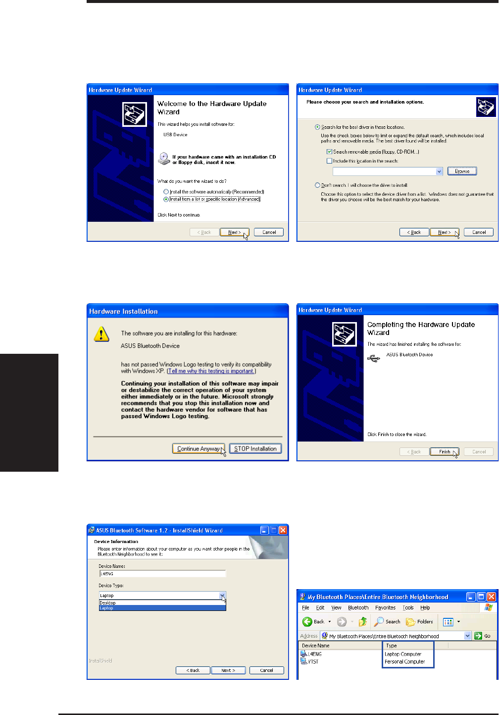
Bluetooth Dongle
The Bluetooth dongle is an optional device. The following gives instructions
on using a Bluetooth dongle with the ASUS SpaceLink B&W PCI Card.
1. When you insert a USB Bluetooth dongle,
“Hardware Update Wizard” will appear. Select
“Install from a list...” and click Next to continue.
2. Select “Search removable...” and click Next
to continue.
3. Click Continue Anyway on driver warnings
when installing devices using bundled drivers. 4. Click Finish when the hardware update is
complete.
When installing software for your Bluetooth
device, you may be asked about your device
type in order to add type information to the “Entire
Bluetooth Neighborhood”.
ASUS SpaceLink B&W PCI Card 61
Chapter 4 - Bluetooth Reference
Chapter 4
If you cannot see any devices within “Entire
Bluetooth Neighborhood”, make sure that your
devices are properly working and set to allow
discovering.
Devices within range will be shown in “Entire
Bluetooth Neighborhood”
Using the Bluetooth Software
By default, Bluetooth devices will have their
discovery option enabled. If you want to know
where this is set, right-click the Bluetooth icon on
the taskbar and choose Setup | Configuration
in order to bring up the configuration window. Use
the “Accessibility” page to “Let other Bluetooth
devices discover this computer”.
Enable Discovering
Depending on your Windows folder options, you will
may see different sized icons. The above has “Show
common tasks in folders” enabled and view “Tiles”.
If your local Bluetooth device is not present or
working, you will get red x’s on each Bluetooth
service icon.
Different Views Bluetooth Not Available
This icon will appear on your desktop. Double-
click to launch the Bluetooth utility. Click Entire Bluetooth Neighborhood to
search for Bluetooth devices in range.
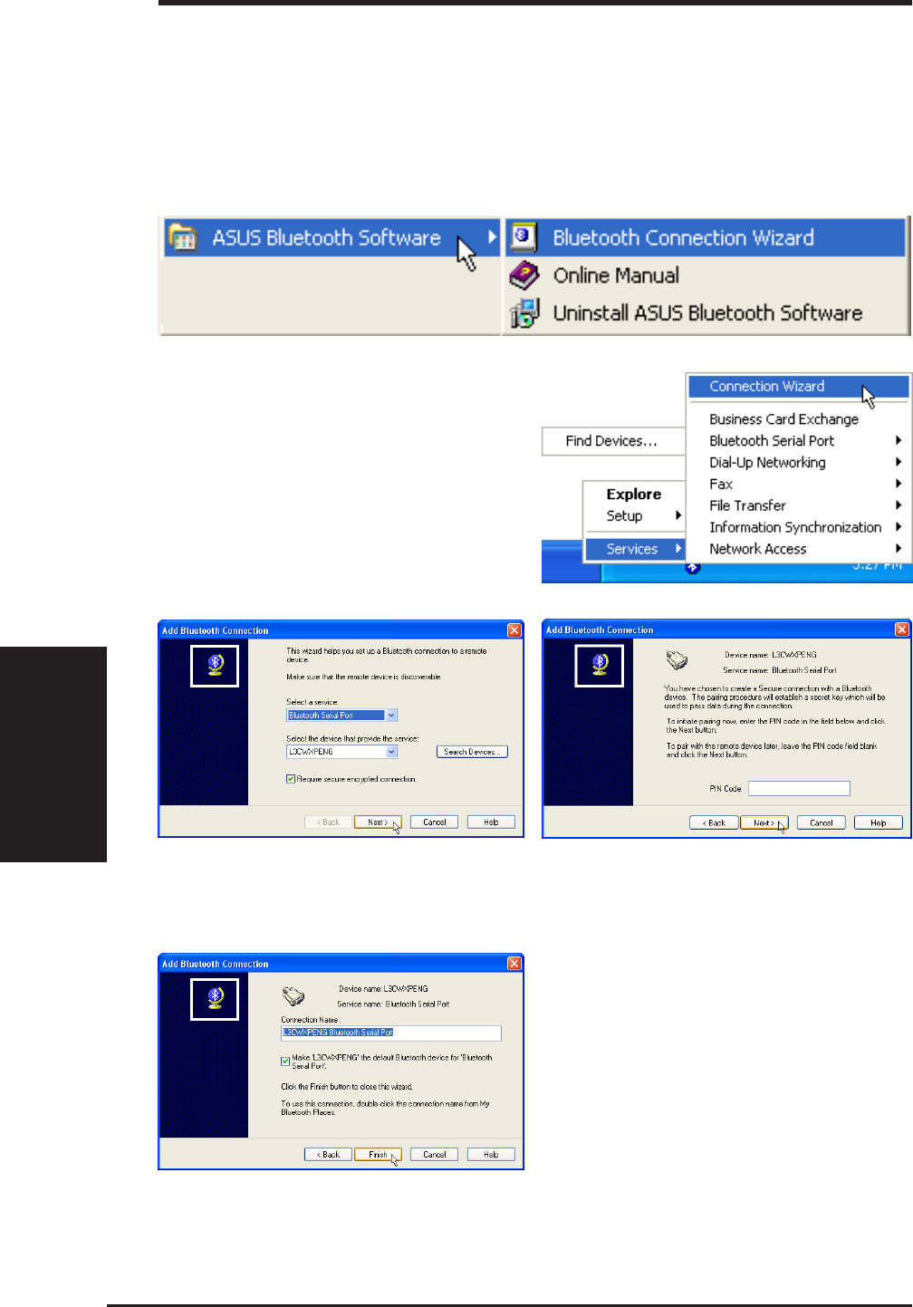
62 ASUS SpaceLink B&W PCI Card
Chapter 4 - Bluetooth Reference
Chapter 4
Bluetooth Connection Wizard
Using “My Bluetooth Places” and browsing to the individual service within a
target device is actually easier to use than using the “Bluetooth Connection
Wizard”. See “Services” a few pages later.
Launch the “Bluetooth Connection Wizard” from
the Start menu or right click the Bluetooth icon
on the taskbar. You can read about “Bluetooth
Connection” in the Online Manual.
Enter a password if necessary.Select a service and target device.
Click Finish when completed.
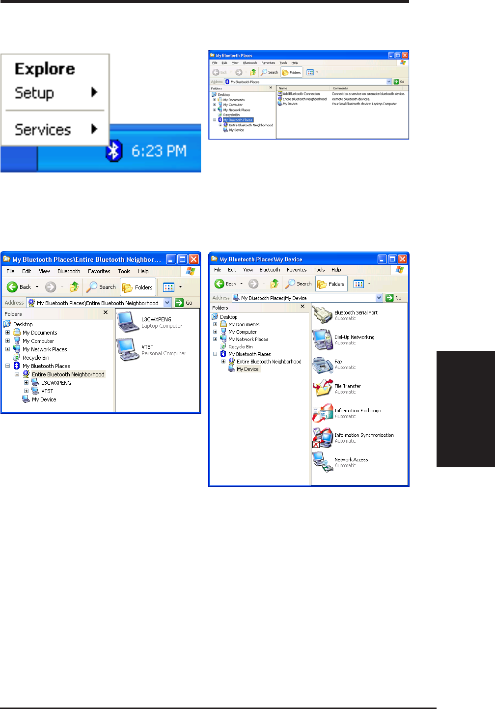
ASUS SpaceLink B&W PCI Card 63
Chapter 4 - Bluetooth Reference
Chapter 4
Besides double-clicking the Bluetooth icon on
your desktop, you can right click and select
Explore to view Bluetooth devices along with
your entire computer in one window.
This is Windows “Explorer” utility with “My
Bluetooth Places” selected.
This is Windows “Explorer” utility with “Entire
Bluetooth Neighborhood” selected. This is Windows “Explorer” utility with “My
Device” selected.
Explore
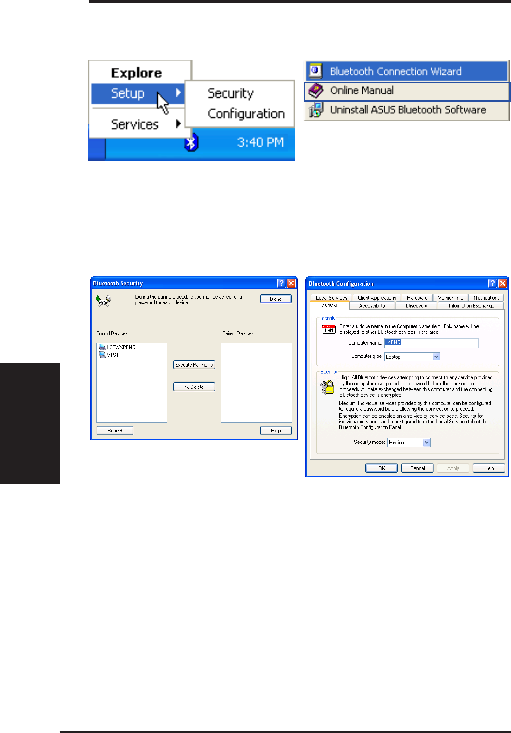
64 ASUS SpaceLink B&W PCI Card
Chapter 4 - Bluetooth Reference
Chapter 4
Right click and select Setup to view Bluetooth
configuration options.
Setup
Security Configuration
You can read about the Security and
Configuration settings in the Online Manual.
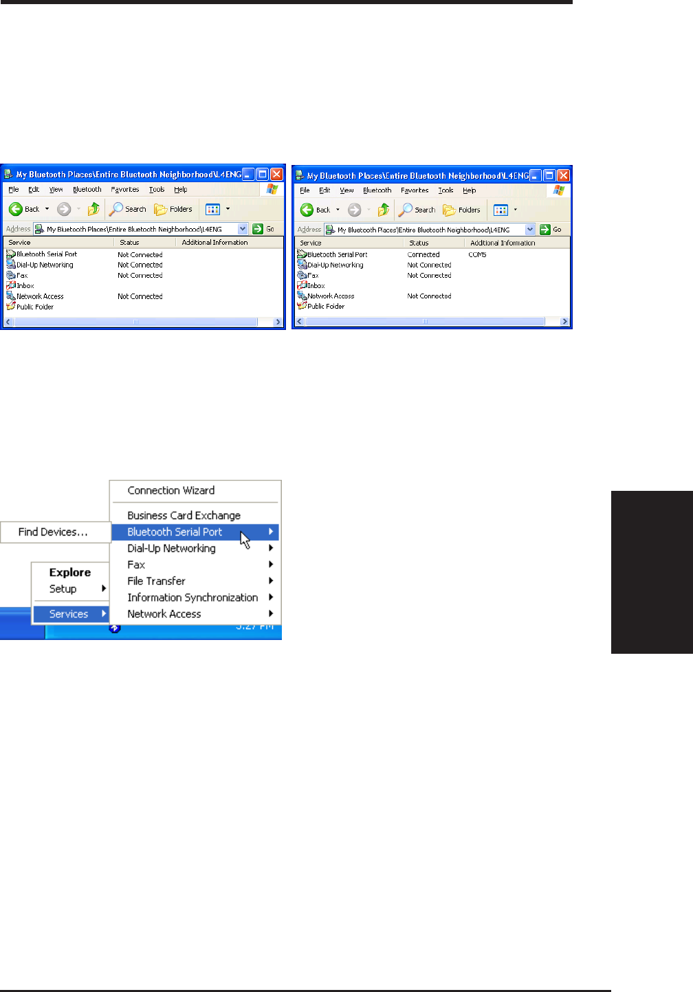
ASUS SpaceLink B&W PCI Card 65
Chapter 4 - Bluetooth Reference
Chapter 4
There are several other services available when
you open the target device. When you double-click a service, the “Status”
will show “Connected”. Because resources are
limited, when you start a service, other services
may be disconnected.
Services
Using services on a target device are just as they would be on your own computer
but you will be borrowing the target device’s resources. For more information on
those services, refer to your source or target’s user’s manual.
You can also use services from the Bluetooth
taskbar icon. Right-click the icon to bring up the
“Services” menu.
See next page for examples of each service.
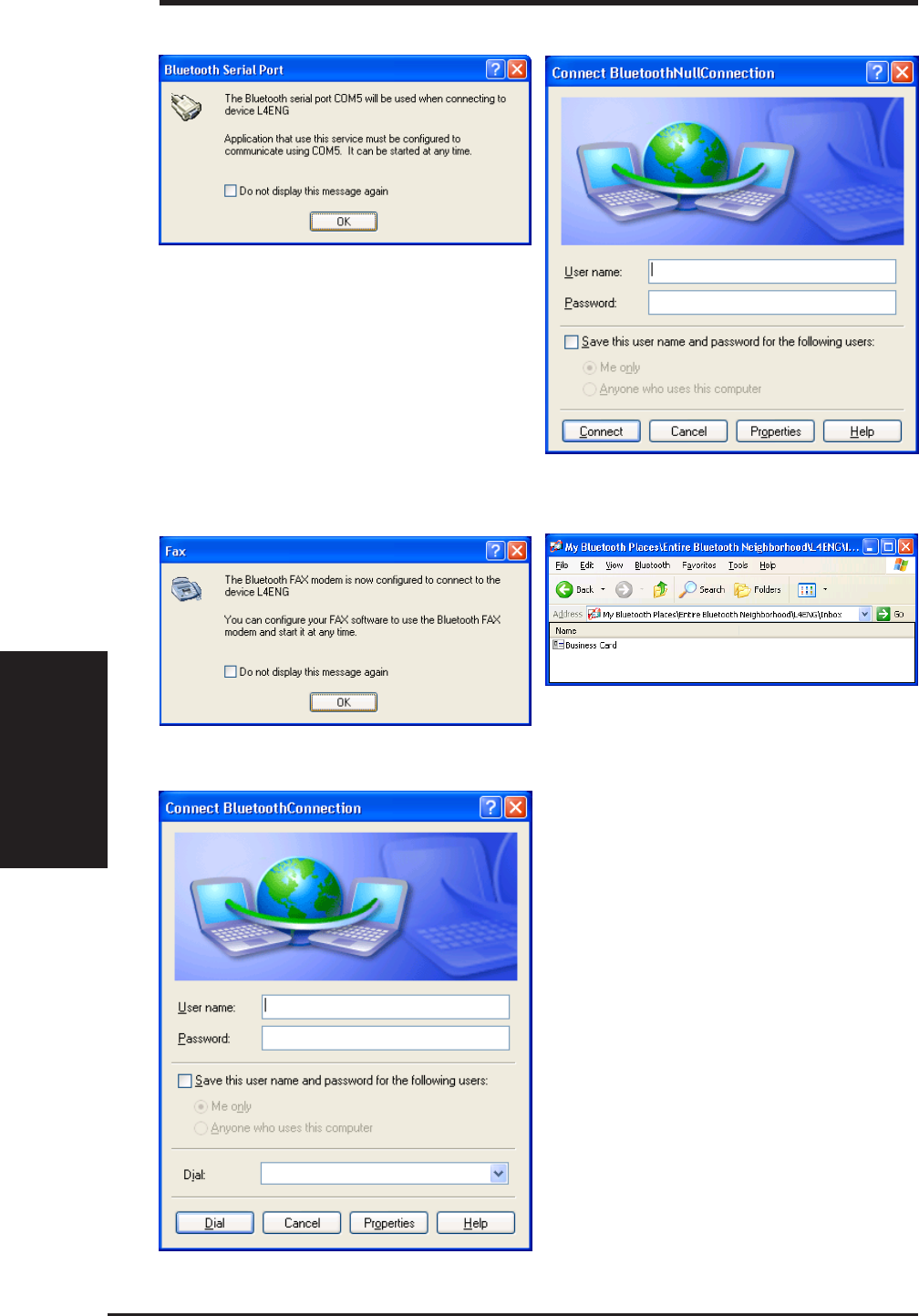
66 ASUS SpaceLink B&W PCI Card
Chapter 4 - Bluetooth Reference
Chapter 4
Network Access
Fax Inbox
Serial Port Dial-Up Networking
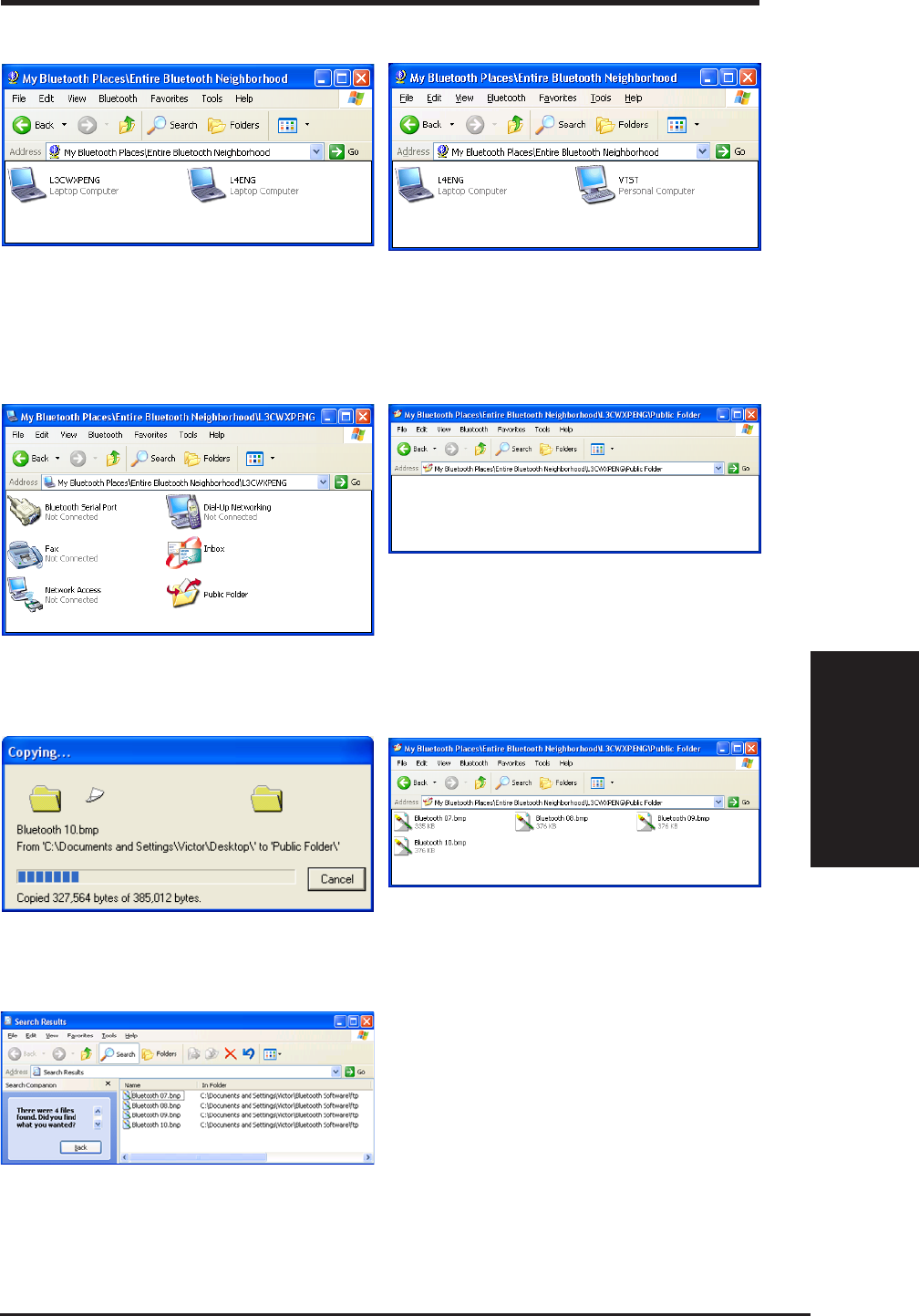
ASUS SpaceLink B&W PCI Card 67
Chapter 4 - Bluetooth Reference
Chapter 4
File Transfer (to Public Folder)
[Source] Selecting “Entire Bluetooth Neighborhood”
will show available Bluetooth devices. You will not
see yourself. The above example is a Personal
Computer (Desktop PC) and only Laptop
Computers (Notebook PC) are shown.
[Source] When you open the target device, the
available services will be shown. Notice the
device name in the “Address”.
[Source] When you open the target device’s
“Public Folder” for the first time, it should be
empty. Notice the device name in the “Address”.
[Source] Drag and drop some files into the
window to begin transferring files. [Source] After copying, you will see the files in
the other device. Notice the device name in the
“Address”.
[Target] You will find the files in the path similar
to the one shown here. If the target device has
a search option, you can use it to locate the files.
[Target] In this setup, there are two Laptop
Computers and one Personal Computer. From
one of the target Laptop Computers, you can
see the Personal Computer that was not shown
in the previous screen capture.
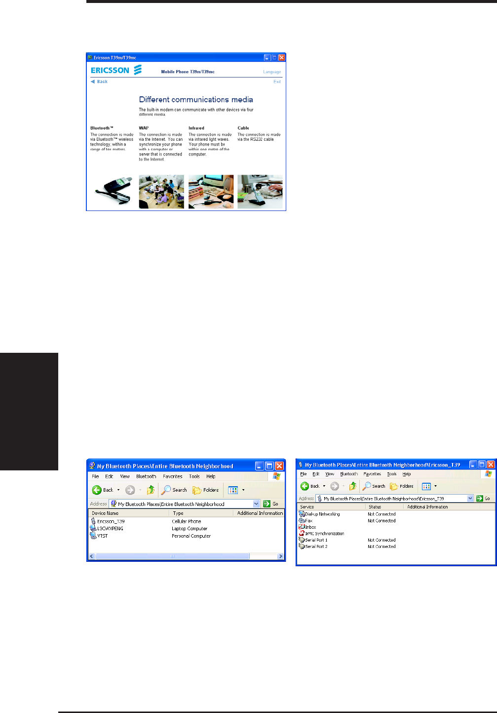
68 ASUS SpaceLink B&W PCI Card
Chapter 4 - Bluetooth Reference
Chapter 4
When using a Bluetooth Cellular phone such as the Ericsson T39, you can see
target Bluetooth devices similar to using a computer. Under (5) Extras menu,
there is (5) Bluetooth options.
(1) Discoverable - use this to allow other to be able to see your Cellular phone.
The Ericsson T39 will only enable this function for 3 mins at a time for security
reasons.
(2) Paired devices - add Bluetooth devices to connect to
(3) Discover - use this to search for available Bluetooth devices.
(4) Operation mode - set the operation mode for the Ericsson T39
Here we can see the Ericsson T39
when using a computer equipped
Bluetooth.
Here are the available services using
the Ericsson T39.
Modern cellular (also called mobile)
phones have several connection options
to make its features accessible to a wide
range of devices and computers in
several environments.
Bluetooth Cellular Phone
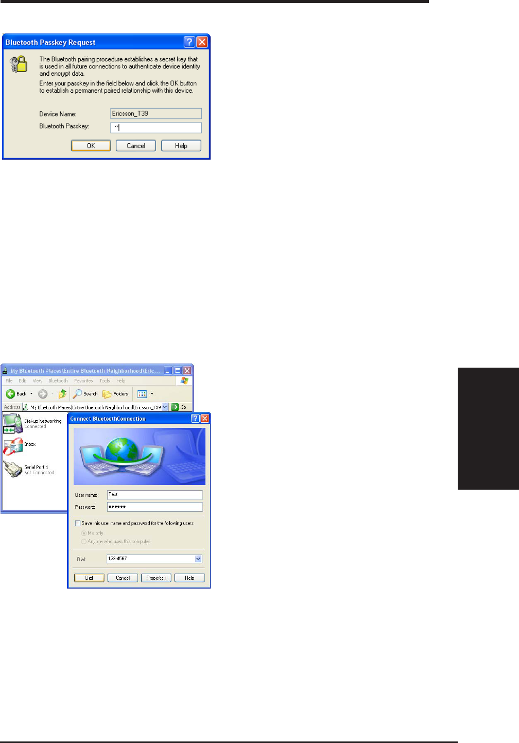
ASUS SpaceLink B&W PCI Card 69
Chapter 4 - Bluetooth Reference
Chapter 4
Dial-Up Networking with Bluetooth Cellular Phone
This is the same as one computer using another computer’s resources to access
the Internet. While on the road, you can borrow your Bluetooth cellular phone’s
modem without connecting a cable. This is like using a computer and a modem
at home to access the Internet through an Internet Service Provider (ISP).
Pairing is necessary in order to utilize
another device’s resources. You will be
asked to enter a password on both
devices. The first device (a computer
in this case) sets the password and the
second device (the Ericsson T39 in this
case) must enter the same password.
Since the Ericsson T39 can only enter
numbers as the password, make sure
you also use numbers as the password
on the computer.
Pairing
To access the Internet, you need to dial-
up to your Internet Service Provider
(ISP), double click “Dial-up
Networking” in the Ericsson_T39
window. Enter your ISP account “User
name”, “Password”, and Phone
Number.

70 ASUS SpaceLink B&W PCI Card
Chapter 5 - Troubleshooting
Chapter 5
5. Troubleshooting
The below troubleshooting guides provide answers to some of the more
common problems, which you may encounter while installing or using
ASUS SpaceLink B&W PCI Card products. If you encounter difficulties
that are not mentioned in this section, please contact ASUS Wireless LAN
Technical Support.
Verify if the PCI Card is installed correctly.
When the ASUS SpaceLink B&W PCI Card setup task is complete, you
can verify if the driver has been setup properly. Right click My Computer,
select Properties, and click the Device Manager tab. Then double-click
the Network adapters icon; you should see “ASUS 11a/b PCI Wireless
Network Adapter” with an icon of expansion card. There should not be a
“!” or “?” (problem) or “x” (disabled) symbol over this icon.
There is a yellow exclamation mark or a yellow question mark in Device
Manager in front of my ASUS SpaceLink B&W PCI Card.
To resolve the problem, you should update/reinstall the ASUS SpaceLink
B&W PCI Card driver. In “Device Manager”, right click ASUS 11a/b PCI
Wireless Network Adapter, select Properties, and select Driver tab. Click
on Update Driver button, then follow the “Update Device Driver Wizard”
to complete the driver installation.
In addition, you may be able to resolve this issue by reinstalling the driver.
Choose ASUS 11a/b PCI Wireless Network Adapter, click Remove button
in “Device Manager”, and then run the Add New Hardware Wizard from
the Control Panel.
Cannot connect to any Access Points
Follow the procedure below to configure your ASUS SpaceLink B&W
PCI Card.
a. Verify that the “Network Type” is in “Infrastructure” mode.
b. Verify that the “SSID” of your ASUS SpaceLink B&W PCI Card is set
to the same “SSID” of an Access Point.
c. Verify that the “Encryption” type is the same as that of an Access Point.
If you enabled “WEP” encryption, you must also set the same WEP
Keys on both sides.

ASUS SpaceLink B&W PCI Card 71
Chapter 5 - Troubleshooting
Chapter 5
Cannot connect to a Station (ASUS SpaceLink B&W PCI Card)
Follow the procedure below to configure your ASUS SpaceLink B&W
PCI Card.
a. Verify that the “Network Type” is in “Ad Hoc” mode.
b. Verify that the “SSID” of your ASUS SpaceLink B&W PCI Card is set
to the same “SSID” of the other station (or another ASUS SpaceLink
B&W PCI Card).
c. Verify that the “channel” of the ASUS SpaceLink B&W PCI Card is
“Auto” or set to the same “channel” of the other station (or another
ASUS SpaceLink B&W PCI Card).
d. Verify that the “Encryption” type is the same as the other station (or
another ASUS SpaceLink B&W PCI Card). If “WEP” encryption is
enabled, you must set the same “WEP” Keys on both stations.
Bad link quality or bad signal strength
There are two possible reasons. First is radio interference, keep the
environment around the ASUS SpaceLink B&W PCI Card away from
microwave ovens and large metal objects. Then try to reorient the ASUS
SpaceLink B&W PCI Card antenna. Second is the distance, decrease the
distance between your ASUS SpaceLink B&W PCI Card and the Access
Point or station (or another ASUS SpaceLink B&W PCI Card).
The TCP/IP protocol did not bind to the SpaceLink PC Card.
This will occur when the computer already has six TCP/IP bindings in
Windows 98 or ten bindings in Windows Me. These limits are imposed by
the Microsoft operating system.
Solution: If your computer already has the maximum number of TCP/IP
bindings, remove one of the network adapters from the Network
configuration before installing the ASUS SpaceLink B&W PCI Card driver.

72 ASUS SpaceLink B&W PCI Card
Chapter 6
Chapter 6 - Glossary
6. Glossary
Access Point (AP)
An networking device that seamlessly connects wired and wireless networks.
Access Points combined with a distributed system support the creation of
multiple radio cells that enable roaming throughout a facility.
Ad Hoc
A wireless network composed solely of stations within mutual
communication range of each other (no Access Point).
Basic Service Area (BSS)
A set of stations controlled by a single coordination function.
Channel
An instance of medium use for the purpose of passing protocol data units
that may be used simultaneously, in the same volume of space, with other
instances of medium use (on other channels) by other instances of the same
physical layer, with an acceptably low frame error ratio due to mutual
interference.
COFDM
See next few pages for detailed explanation.
Direct-Sequence Spread Spectrum
See next few pages for detailed explanation.
Extended Service Set (ESS)
A set of one or more interconnected basic service set (BSSs) and integrated
local area networks (LANs) can be configured as an Extended Service Set.
Ethernet
The most widely used LAN access method, which is defined by the IEEE
802.3 standard. Ethernet is normally a shared media LAN meaning all
devices on the network segment share total bandwidth. Ethernet networks
operate at 10Mbps using CSMA/CD to run over 10-BaseT cables.

ASUS SpaceLink B&W PCI Card 73
Chapter 6
Chapter 6 - Glossary
Gateway
A network component that acts as an entrance to another network.
IEEE 802.11
IEEE 802.xx is a set of specifications for LANs from the Institute of
Electrical and Electronic Engineers (IEEE). Most wired networks conform
to 802.3, the specification for CSMA/CD based Ethernet networks or 802.5,
the specification for token ring networks. 802.11 defines the standard for
wireless LANs encompassing three incompatible (non-interoperable)
technologies: Frequency Hopping Spread Spectrum (FHSS), Direct
Sequence Spread Spectrum (DSSS), and Infrared. 802.11 specifies a carrier
sense media access control and physical layer specifications for 1 and 2
Mbps wireless LANs.
IEEE 802.11a / IEEE 802.11b
See next few pages for detailed explanations.
Infrastructure
A wireless network centered about an access point. In this environment,
the access point not only provides communication with the wired network
but also mediates wireless network traffic in the immediate neighborhood.
IP (Internet Protocol)
The TCP/IP standard protocol that defines the IP datagram as the unit of
information passed across an Internet and provides the basis for
connectionless packet delivery service. IP includes the ICMP control and
error message protocol as an integral part. It provides the functional
equivalent of ISO OSI Network Services.
IP Address
An IP address is a 32-bit number that identifies each sender or receiver of
information that is sent across the Internet. An IP address has two parts: the
identifier of a particular network on the Internet and an identifier of the
particular device (which can be a server or a workstation) within that network.
ISM Bands (Industrial, Scientific, and Medicine Bands)
Radio frequency bands that the Federal Communications Commission
(FCC) authorized for wireless LANs. The ISM bands are located at 902
MHz, 2.400 GHz, and 5.7 GHz.

74 ASUS SpaceLink B&W PCI Card
Chapter 6
Chapter 6 - Glossary
ISP (Internet Service Provider)
An organization that provides access to the Internet. Small ISPs provide
service via modem and ISDN while the larger ones also offer private line
hookups (T1, fractional T1, etc.).
LAN (Local Area Network)
A communications network that serves users within a defined geographical
area. The benefits include the sharing of Internet access, files and equipment
like printers and storage devices. Special network cabling (10 Base-T) is
often used to connect the PCs together.
NIC (Network Interface Card)
A network adapter inserted into a computer so that the computer can be
connected to a network. It is responsible for converting data from stored in
the computer to the form transmitted or received.
Packet
A basic message unit for communication across a network. A packet usually
includes routing information, data, and sometimes error detection
information.
PCMCIA (Personal Computer Memory Card International Association)
The Personal Computer Memory Card International Association (PCMCIA),
develops standards for PC cards, formerly known as PCMCIA cards. These
cards are available in three types, and are have about the same length and
width as credit cards. However, the different width of the cards ranges in
thickness from 3.3 mm (Type I) to 5.0 mm (Type II) to 10.5 mm (Type III).
These cards can be used for various functions, including memory storage,
landline modems and wireless modems.
Radio Frequency (RF) Terms: GHz, MHz, Hz
The international unit for measuring frequency is Hertz (Hz), equivalent to
the older unit of cycles per second. One megahertz (MHz) is one million
Hertz. One gigahertz (GHz) is one billion Hertz. The standard US electrical
power frequency is 60 Hz, the AM broadcast radio frequency band is 0.55-
1.6 MHz, the FM broadcast radio frequency band is 88-108 MHz, and
wireless 802.11 LANs operate at 2.4 GHz.

ASUS SpaceLink B&W PCI Card 75
Chapter 6
Chapter 6 - Glossary
SSID (Service Set ID)
SSID is a group name shared by every member of a wireless network. Only
client PCs with the same SSID are allowed to establish a connection.
Station
Any device containing IEEE 802.11 wireless medium access conformity.
TCP (Transmission Control Protocol)
The standard transport level protocol that provides the full duplex, stream
service on which many application protocols depend. TCP allows a process
or one machine to send a stream of data to a process on another. Software
implementing TCP usually resides in the operating system and uses the IP
to transmit information across the network.

76 ASUS SpaceLink B&W PCI Card
Chapter 6
Chapter 6 - Glossary
IEEE 802.11b (11Mbits/sec)
In 1997, the Institute of Electrical and Electronics Engineers (IEEE) adopted
the 802.11 standard for wireless devices operating in the 2.4 GHz frequency
band. This standard includes provisions for three radio technologies: direct
sequence spread spectrum, frequency hopping spread spectrum, and
infrared. Devices that comply with the 802.11 standard operate at a data
rate of either 1 or 2 Mbps.
In 1999, the IEEE created the 802.11b standard. 802.11b is essentially
identical to the 802.11 standard except 802.11b provides for data rates of
up to 11 Mbps for direct sequence spread spectrum devices. Under 802.11b,
direct sequence devices can operate at 11 Mbps, 5.5 Mbps, 2 Mbps, or 1
Mbps. This provides interoperability with existing 802.11 direct sequence
devices that operate only at 2 Mbps.
Direct sequence spread spectrum devices spread a radio signal over a range
of frequencies. The IEEE 802.11b specification allocates the 2.4 GHz
frequency band into 14 overlapping operating Channels. Each Channel
corresponds to a different set of frequencies. See the Appendix to determine
the center frequency used by each Channel.
If operating multiple 802.11b Wireless PCI Cards in the same vicinity, the
distance between the center frequencies must be at least 25 MHz to avoid
interference. Note that the Channels available to an 802.11b Wireless PCI
Card will vary from country to country. In the United States, the 802.11b
standard allocates 11 operating Channels for direct sequence devices. Channels
1, 6, and 11 are independent and do not overlap with each other. To avoid
interference between 802.11b Wireless PCI Cards, It is recommended that
you configure the Wireless PCI Cards using only Channels 1, 6, and 11.

ASUS SpaceLink B&W PCI Card 77
Chapter 6
Chapter 6 - Glossary
Direct-Sequence Spread Spectrum (for 802.11b)
Spread spectrum (broadband) uses a narrowband signal to spread the
transmission over a segment of the radio frequency band or spectrum. Direct-
sequence is a spread spectrum technique where the transmitted signal is
spread over a particular frequency range. The Space Link Wireless PCI
Card uses Direct-Sequence Spread Spectrum (DSSS) for radio
communication.
Direct-sequence systems communicate by continuously transmitting a
redundant pattern of bits called a chipping sequence. Each bit of transmitted
data is mapped into chips by the Wireless PCI Card and rearranged into a
pseudorandom spreading code to form the chipping sequence. The chipping
sequence is combined with a transmitted data stream to produce the Wireless
PCI Card output signal.
Wireless mobile clients receiving a direct-sequence transmission use the
spreading code to map the chips within the chipping sequence back into
bits to recreate the original data transmitted by the Wireless PCI Card.
Intercepting and decoding a direct-sequence transmission requires a
predefined algorithm to associate the spreading code used by the transmitting
Wireless PCI Card to the receiving wireless mobile client.
This algorithm is established by IEEE 802.11b specifications. The bit
redundancy within the chipping sequence enables the receiving wireless
mobile client to recreate the original data pattern, even if bits in the chipping
sequence are corrupted by interference. The ratio of chips per bit is called
the spreading ratio. A high spreading ratio increases the resistance of the
signal to interference. A low spreading ratio increases the bandwidth
available to the user. The Wireless PCI Card uses a constant chip rate of
11Mchips/s for all data rates, but uses different modulation schemes to
encode more bits per chip at the higher data rates. The Wireless PCI Card
is capable of an 11 Mbps data transmission rate, but the coverage area is
less than a 1 or 2 Mbps Wireless PCI Card since coverage area decreases as
bandwidth increases.

78 ASUS SpaceLink B&W PCI Card
Chapter 6
Chapter 6 - Glossary
IEEE 802.11a (54Mbits/sec)
The 802.11b standard was designed to operate in the 2.4-GHz ISM
(Industrial, Scientific and Medical) band using direct-sequence spread-
spectrum technology. The 802.11a standard, on the other hand, was designed
to operate in the more recently allocated 5-GHz UNII (Unlicensed National
Information Infrastructure) band. And unlike 802.11b, the 802.11a standard
departs from the traditional spread-spectrum technology, instead using a
frequency division multiplexing scheme that's intended to be friendlier to
office environments.
The 802.11a standard, which supports data rates of up to 54 Mbps, is the
Fast Ethernet analog to 802.11b, which supports data rates of up to 11
Mbps. Like Ethernet and Fast Ethernet, 802.11b and 802.11a use an identical
MAC (Media Access Control). However, while Fast Ethernet uses the same
physical-layer encoding scheme as Ethernet (only faster), 802.11a uses an
entirely different encoding scheme, called OFDM (orthogonal frequency
division multiplexing).
The 802.11b spectrum is plagued by saturation from wireless phones,
microwave ovens and other emerging wireless technologies, such as
Bluetooth. In contrast, 802.11a spectrum is relatively free of interference.
The 802.11a standard gains some of its performance from the higher
frequencies at which it operates. The laws of information theory tie
frequency, radiated power and distance together in an inverse relationship.
Thus, moving up to the 5-GHz spectrum from 2.4 GHz will lead to shorter
distances, given the same radiated power and encoding scheme.

ASUS SpaceLink B&W PCI Card 79
Chapter 6
Chapter 6 - Glossary
COFDM (for 802.11a)
Power alone is not enough to maintain 802.11b-like distances in an 802.11a
environment. To compensate, vendors specified and designed a new
physical-layer encoding technology that departs from the traditional direct-
sequence technology being deployed today. This technology is called
COFDM (coded OFDM). COFDM was developed specifically for indoor
wireless use and offers performance much superior to that of spread-
spectrum solutions. COFDM works by breaking one high-speed data carrier
into several lower-speed subcarriers, which are then transmitted in parallel.
Each high-speed carrier is 20 MHz wide and is broken up into 52
subchannels, each approximately 300 KHz wide. COFDM uses 48 of these
subchannels for data, while the remaining four are used for error correction.
COFDM delivers higher data rates and a high degree of multipath reflection
recovery, thanks to its encoding scheme and error correction.
Each subchannel in the COFDM implementation is about 300 KHz wide.
At the low end of the speed gradient, BPSK (binary phase shift keying) is
used to encode 125 Kbps of data per channel, resulting in a 6,000-Kbps, or
6 Mbps, data rate. Using quadrature phase shift keying, you can double the
amount of data encoded to 250 Kbps per channel, yielding a 12-Mbps data
rate. And by using 16-level quadrature amplitude modulation encoding 4
bits per hertz, you can achieve a data rate of 24 Mbps. The 802.11a standard
specifies that all 802.11a-compliant products must support these basic data
rates. The standard also lets the vendor extend the modulation scheme
beyond 24 Mbps. Remember, the more bits per cycle (hertz) that are
encoded, the more susceptible the signal will be to interference and fading,
and ultimately, the shorter the range, unless power output is increased.

80 ASUS SpaceLink B&W PCI Card
Chapter 7
Chapter 7 - Safety Information
7. Safety Information
Federal Communications Commission Statement
This device complies with FCC Rules Part 15. Operation is subject to the following
two conditions:
• This device may not cause harmful interference, and
• This device must accept any interference received, including interference that
may cause undesired operation.
This equipment has been tested and found to comply with the limits for a class B
digital device, pursuant to Part 15 of the Federal Communications Commission (FCC)
rules. These limits are designed to provide reasonable protection against harmful
interference in a residential installation. This equipment generates, uses, and can
radiate radio frequency energy and, if not installed and used in accordance with the
instructions, may cause harmful interference to radio communications. However,
there is no guarantee that interference will not occur in a particular installation. If
this equipment does cause harmful interference to radio or television reception, which
can be determined by turning the equipment off and on, the user is encouraged to try
to correct the interference by one or more of the following measures:
• Reorient or relocate the receiving antenna.
• Increase the separation between the equipment and receiver.
• Connect the equipment into an outlet on a circuit different from that to which
the receiver is connected.
• Consult the dealer or an experienced radio/TV technician for help.
WARNING! The use of a shielded-type power cord is required in
order to meet FCC emission limits and to prevent interference to
the nearby radio and television reception. It is essential that only
the supplied power cord be used. Use only shielded cables to con-
nect I/O devices to this equipment. You are cautioned that changes
or modifications not expressly approved by the party responsible
for compliance could void your authority to operate the equipment.
Reprinted from the Code of Federal Regulations #47, part 15.193, 1993. Washington
DC: Office of the Federal Register, National Archives and Records Administration,
U.S. Government Printing Office.

ASUS SpaceLink B&W PCI Card 81
Chapter 7
Chapter 7 - Safety Information
Canadian Department of Communications
This digital apparatus does not exceed the Class B limits for radio noise emissions
from digital apparatus set out in the Radio Interference Regulations of the Canadian
Department of Communications.
This Class B digital apparatus complies with Canadian ICES-003.
Cet appareil numérique de la classe B est conforme à la norme
NMB-003 du Canada.
Regulatory information / Disclaimers
Installation and use of this Wireless LAN device must be in strict accordance
with the instructions included in the user documentation provided with the
product. Any changes or modifications (including the antennas) made to this
device that are not expressly approved by the manufacturer may void the user's
authority to operate the equipment. The manufacturer is not responsible for
any radio or television interference caused by unauthorized modification of
this device, or the substitution of the connecting cables and equipment other
than manufacturer specified. It is the responsibility of the user to correct any
interference caused by such unauthorized modification, substitution or
attachment. Manufacturer and its authorized resellers or distributors will assume
no liability for any damage or violation of government regulations arising from
failing to comply with these guidelines.
CAUTION: To maintain compliance with FCC's RF exposure guide-
lines, this equipment should be installed and operated with minimum
distance [20cm] between the radiator and your body. Use on the sup-
plied antenna. Unauthorized antenna, modification, or attachments
could damage the transmitter and may violate FCC regulations.
MPE Statement (Safety Information)
Your device contains a low power transmitter. When device is transmitted it
sends out Radio Frequency (RF) signal.
Safety Information
In order to maintain compliance with the FCC RF exposure guidelines, this
equipment should be installed and operated with minimum distance [20cm]
between the radiator and your body. Use only with supplied antenna.
Unauthorized antenna, modification, or attachments could damage the
transmitter and may violate FCC regulations.

82 ASUS SpaceLink B&W PCI Card
Chapter 7
Chapter 7 - Safety Information
Caution Statement of the FCC Radio Frequency Exposure
This Wireless LAN radio device has been evaluated under FCC Bulletin OET
65C and found compliant to the requirements as set forth in CFR 47 Sections
2.1091, 2.1093, and 15.247(b)(4) addressing RF Exposure from radio frequency
devices. The radiation output power of this Wireless LAN device is far below
the FCC radio frequency exposure limits. Nevertheless, this device shall be
used in such a manner that the potential for human contact during normal
operation – as a mobile or portable device but use in a body-worn way is
strictly prohibit. When using this device, a certain separation distance between
antenna and nearby persons has to be kept to ensure RF exposure compliance.
In order to comply with the RF exposure limits established in the ANSI C95.1
standards, the distance between the antennas and the user should not be less
than [20cm].
SAR Exposure
This device has been tested for compliance with FCC RF Exposure (SAR)
limits in typical laptop configurations.
In order to comply with SAR limits established in the ANSI C95.1 standards,
it is recommended when using a PC card adapter that the integrated antenna is
positioned more than [20cm] from your body or nearby persons during extended
periods of operation. If the antenna is positioned less than [20cm] from the
user, it is recommended that the user limit the exposure time.
Radio Frequency Interference Requirements
This device is restricted to INDOOR USE due to its operation in the 5.15 to
5.25GHz frequency range. FCC requires this product to be used indoors for
the frequency range 5.15 to 5.25GHz to reduce the potential for harmful
interference to co-channel of the Mobile Satellite Systems.
High power radars are allocated as primary user of the 5.25 to 5.35GHz and
5.65 to 5.85GHz bands. These radar stations can cause interference with and /
or damage this device

April 5, 2002 WIDCOMM i
Wireless Internet and Data Communication
9645 Scranton Road, Suite 205
San Diego, CA 92121
Phone: 858.453.8400
Fax: 858.453.5735
Email
Technical Support: support@widcomm.com
Information: info@widcomm.com
BTW Configuration & User’s Guide
April 5, 2002
Document Number: (011107-1006-BTW_btw1.2_docs_BTWDocs.doc)
Version: 1.2
Confidential and Proprietary Information
BTW Configuration & User’s Guide
April 5, 2002 WIDCOMM i
LICENSED SOFTWARE
© Copyright 2000 – 2002, WIDCOMM, Inc. (“WIDCOMM”). All rights reserved.
Warning: This software and accompanying documentation are protected by copyright law and
international treaties. Unauthorized reproduction or distribution of this software, or any portion of it, may
result in severe civil and criminal penalties, and will be prosecuted to the maximum extent possible under
the law.
Use of this software is governed by the terms of the end user license agreement that accompanies or is
included with such software. Unless otherwise noted in the end user license agreement, or herein, no part of
the documentation accompanying this software, whether provided in printed or electronic form may be
reproduced in any form, or stored in a database or retrieval system, or transmitted in any form or by any
means, or used to make any derivative work (such as translation, transformation, or adaptation) without the
express, prior written consent of WIDCOMM.
Trademark(s) ™ and Registered Trademark(s) ®
WIDCOMM and the WIDCOMM logo are trademarks of WIDCOMM, Inc.
Bluetooth and the Bluetooth logos are trademarks owned by Bluetooth SIG, Inc., U.S.A. and licensed to
WIDCOMM, Inc.
Microsoft, Windows, Outlook are registered trademarks of Microsoft Corporation.
Other brand and product names may be registered trademarks or trademarks of their respective holders.
Winroute Lite is Copyright Tiny Software, Inc.
BTW Configuration & User’s Guide Table of Contents
April 5, 2002 WIDCOMM ii
Table of Contents
1 Introduction............................................................................................................................................ 1
1.1 INTRODUCTION TO BLUETOOTH..................................................................................................... 1
1.2 INTRODUCTION TO BTW ............................................................................................................... 2
1.3 BLUETOOTH DEVICE IDENTITY...................................................................................................... 3
1.4 ICONS USED FOR BLUETOOTH DEVICES AND SERVICES................................................................. 4
1.5 WHAT'S NEW................................................................................................................................. 6
2 Basic Operations .................................................................................................................................... 7
2.1 FIND BLUETOOTH DEVICES ........................................................................................................... 7
2.2 FIND A SERVICE ............................................................................................................................ 8
2.3 DETERMINE A CONNECTION’S STATUS.......................................................................................... 9
2.4 USING THE CONNECTION WIZARD............................................................................................... 10
2.4.1 Setup a new connection.................................................................................................... 10
2.5 BLUETOOTH TRAY....................................................................................................................... 11
3 Client Applications............................................................................................................................... 12
3.1 NETWORK ACCESS ...................................................................................................................... 12
3.1.1 Windows 2000, Server-side Setup ................................................................................... 12
3.1.2 Windows XP, Server-side Setup...................................................................................... 12
3.1.3 Windows 98SE & Windows Me, Server-side Setup........................................................ 13
3.1.3.1 Configure the server:....................................................................................... 13
3.1.3.2 Configure the routing software: ...................................................................... 13
3.2 BLUETOOTH SERIAL PORT........................................................................................................... 14
3.3 DIAL-UP NETWORKING................................................................................................................ 15
3.4 FAX ............................................................................................................................................. 15
3.5 FILE TRANSFER............................................................................................................................ 16
3.5.1 Types of File Transfer operations .................................................................................... 16
3.6 INFORMATION EXCHANGE........................................................................................................... 17
3.7 INFORMATION SYNCHRONIZATION .............................................................................................. 18
4 Local Services...................................................................................................................................... 19
4.1 LOCAL SERVICES......................................................................................................................... 19
5 Configuration Panel ............................................................................................................................. 20
5.1 ACCESSIBILITY TAB..................................................................................................................... 20
5.1.1 Adding and Deleting Devices .......................................................................................... 20
5.2 DISCOVERY TAB.......................................................................................................................... 21
5.3 GENERAL CONFIGURATION SETTINGS ......................................................................................... 22
5.4 HARDWARE CONFIGURATION...................................................................................................... 23
5.4.1 Hardware Advanced Settings Dialog Box........................................................................ 24
5.5 INFORMATION EXCHANGE CONFIGURATION SETTINGS ............................................................... 25
5.5.1 File Transfer..................................................................................................................... 25
5.5.2 Send Business Card.......................................................................................................... 25
5.5.3 Receive Business Card..................................................................................................... 25
5.6 LOCAL SERVICES TAB ................................................................................................................. 26
5.6.1 Property settings which are common to all of the local services...................................... 26
5.6.2 To add a user- defined Bluetooth Serial Port ................................................................... 27
5.6.3 To remove a user-defined Bluetooth Serial Port.............................................................. 27
5.7 NOTIFICATIONS TAB.................................................................................................................... 28
5.8 VERSION INFO CONFIGURATION.................................................................................................. 28
(Continued on the next page)
BTW Configuration & User’s Guide Table of Contents
April 5, 2002 WIDCOMM iii
(Continued from the previous page)
6 Security ................................................................................................................................................ 29
6.1 INTRODUCTION ............................................................................................................................ 29
6.2 AUTHENTICATION........................................................................................................................ 29
6.3 AUTHORIZATION.......................................................................................................................... 29
6.4 ENCRYPTION................................................................................................................................ 30
6.5 LEVELS OF SECURITY .................................................................................................................. 30
6.6 LINK KEY .................................................................................................................................... 30
6.7 PAIRING DEVICES ........................................................................................................................ 31
6.8 PASSKEY...................................................................................................................................... 31
6.9 SECURITY REQUEST DIALOG BOX ............................................................................................... 32
6.10 SECURITY REQUEST DIALOG BOX, ADVANCED BUTTON ............................................................ 32
7 Technical Support ................................................................................................................................ 33
8 Troubleshooting ................................................................................................................................... 34
9 Glossary ............................................................................................................................................... 36
BTW Configuration & User’s Guide Introduction
April 5, 2002 WIDCOMM 1
1 Introduction
1.1 INTRODUCTION TO BLUETOOTH
The term “Bluetooth” refers to a worldwide standard for the wireless exchange of data
between two devices.
In order to exchange data, two Bluetooth devices must establish a connection.
Before a connection is established, one device must request a connection with another.
The second device accepts (or rejects) the connection.
The originator of the request is known as the client.
The device that accepts (or rejects) the request is known as the server.
Many Bluetooth devices can act as both client and server.
A client Bluetooth device runs a software program that requests a connection to another
device as part of its normal operation. For example, the program may request a
connection to a remote computer, a printer, or a modem.
Becoming a Bluetooth client normally requires an action by the device operator, such as
an attempt to browse a remote computer, print a file, or dial out on a modem.
Every Bluetooth device that provides a service must be prepared to respond to a
connection request. Bluetooth software is always running in the background on the
server, ready to respond to connection requests.
BTW Configuration & User’s Guide Introduction
April 5, 2002 WIDCOMM 2
1.2 INTRODUCTION TO BTW
BTW is the solution for the seamless integration of Bluetooth technology into personal
computers.
For an overview of the features added in this release, see What's New.
Most Bluetooth-enabled devices have the capability to act as:
• A Bluetooth server—these devices provide one or more services, such as access
to the Internet, to other Bluetooth devices.
• A Bluetooth client—these devices use the service(s) provided by Bluetooth
servers.
Bluetooth devices that can act as both server and client can often do both at the same
time.
BTW provides:
• Clients with the means:
! To locate other Bluetooth devices in the immediate vicinity (inquiry)
! Discover the services that those devices offer (discovery)
! Connect to, use, and disconnect from those services.
• Servers with the means to include/exclude individual services in the list of
services they provide to clients.
• Extensive security, including:
! Authorization
! Authentication
! Encryption.
BTW supports
• Windows 2000.
• Windows 98SE (Second Edition).
• Windows Me (Millennium Edition)
• Windows XP Professional
• Windows XP Home Edition.
BTW functions the same way, regardless of the supported version of Windows on which
it is running.
BTW Configuration & User’s Guide Introduction
April 5, 2002 WIDCOMM 3
The services supported by BTW are:
• Bluetooth Serial Port—establishes a Bluetooth wireless connection between
two devices. The connection may be used by applications as though a physical
serial cable connected the devices.
• Dial-up Networking—allows a Bluetooth client to use a modem that is
physically attached to the Bluetooth server.
• Fax—allows a Bluetooth client to wirelessly send a fax using a device that is
physically attached to the Bluetooth server.
• File Transfer—establishes a Bluetooth wireless connection that allows your
computer to perform file system operations on another Bluetooth-enabled
device—browse, drag/drop, open, print, cut/copy, paste, delete, rename, etc.
• Information Exchange—establishes a Bluetooth wireless connection between
two devices so that they can exchange personal information manager data such as
business cards, calendar items, email messages, and notes.
• Information Synchronization—establishes a Bluetooth wireless connection
between two devices and uses the connection to synchronize Personal
Information Manager data between the two devices.
• Network Access—establishes a Bluetooth wireless connection between the client
and a server that is physically connected to the Local Area Network. If the client
has permission (user name and password for the LAN), the wireless connection
can be used as if the client were hardwired to the LAN.
All Bluetooth servers do not necessarily provide all of these services. For example, a
network gateway may only provide access to the Local Area Network (the Network
Access service).
To determine the services provided by a Bluetooth device:
1. On the client, in the Folders pane of My Bluetooth Places, select Entire Bluetooth
Neighborhood.
2. In the right pane of Entire Bluetooth Neighborhood, right-click anywhere except
on a device name and select Refresh from the pop-up menu.
In the Folders pane of My Bluetooth Places, right-click a device and select Discover
Available Services from the pop-up menu to update the available services list. The
available services will be displayed in the right pane of My Bluetooth Places.
1.3 BLUETOOTH DEVICE IDENTITY
Every Bluetooth device has a unique 48-bit binary Bluetooth Device Address (BDA)
burned into its Read-Only Memory (ROM). This address cannot be changed by the end-
user.
A device’s BDA is usually displayed in hexadecimal format; 00:D0:B7:03:2E:9F is a
valid BDA.
Each Bluetooth device also has an operator-configurable, user-friendly name to help
distinguish it from other Bluetooth devices. The user-friendly name may be up to 99
alphanumeric characters in length and may contain spaces. My Personal Computer is a
valid user-friendly name.
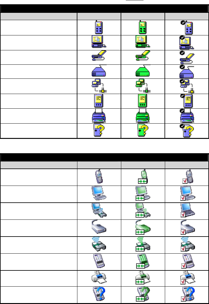
BTW Configuration & User’s Guide Introduction
April 5, 2002 WIDCOMM 4
1.4 ICONS USED FOR BLUETOOTH DEVICES AND SERVICES
Bluetooth icons provide at-a-glance feedback about a device or service's status by
changing appearance.
Device icons are shown in Table 1 and Table 2.
Table 1: Device icons for all operating systems Except Windows XP
Device Icons (except Windows XP, see below)
Device Type Normal Connected Paired
Cellular Telephone
Desktop Computer
Laptop Computer
Modem
Network Access Point
Personal Digital Assistant
Printer
Unknown Devices
Table 2: Device icons for Windows XP
Windows XP Device Icons
Device Type Normal Connected Paired
Cellular Telephone
Desktop Computer
Laptop Computer
Modem
Network Access Point
Personal Digital Assistant
Printer
Unknown Devices
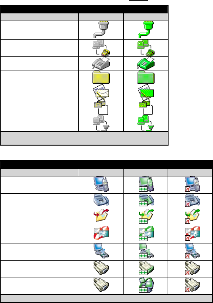
BTW Configuration & User’s Guide Introduction
April 5, 2002 WIDCOMM 5
Service icons are shown in Table 3 and Table 4.
Table 3: Service icons for all operating systems Except Windows XP
Service Icons (except Windows XP, see below)
Service Name Normal Connected
Bluetooth Serial Port
Dial-up Networking
Fax
File Transfer
Information Exchange
Information Synchronization
Network Access
* Services may be unavailable because they are in use or because the necessary
hardware is not installed.
Table 4: Service icons for Windows XP
Windows XP Service Icons
Service Type Normal Connected Unavailable*
Dial-up Networking
Fax
File Transfer
Information Exchange
Network Access
Serial Port
Information Synchronization
*
Services may be unavailable because they are in use or because the necessary hardware is not installed.
BTW Configuration & User’s Guide Introduction
April 5, 2002 WIDCOMM 6
1.5 WHAT'S NEW
• A Connection Wizard now helps you set up new connections and places a
shortcut to the new connection in My Bluetooth Places.
! Extensive right-click context sensitive menu support throughout, including
the ability to:
! Access the Bluetooth Configuration Panel.
! Create connection shortcuts.
! Discover services.
! Display connection status.
! Display properties for connections, shortcuts to connections, local devices
and services, remote devices and services.
! Open and close connections.
! Pair and un-pair devices.
! Refresh lists of devices, services, and folder contents.
• Context sensitive What’s This Help in the Bluetooth Configuration Panel.
• A Relative Signal Strength Indicator/Properties dialog box has been added for
every connection. right-click the connection and select Status to display the
dialog box.
• Enhanced Windows system tray functions that provide quick access to:
! My Bluetooth Places; double-click the Bluetooth icon
! Speedy connection establishment; Right-click the Bluetooth icon, select
Services, and then the service you want. BTW shows you only the devices
that offer that service.
! The Connection Wizard.
BTW Configuration & User’s Guide Basic Operations
April 5, 2002 WIDCOMM 7
2 Basic Operations
2.1 FIND BLUETOOTH DEVICES
“Search for Devices” looks for Bluetooth devices in the vicinity and displays the devices
it finds in My Bluetooth Places.
To start the Search for Devices:
• In the Folders pane of My Bluetooth Devices, select (highlight) a device name
• Open the Bluetooth menu and select Search for Devices.
The Bluetooth menu is only visible when My Bluetooth Places is active.
BTW can be configured to automatically search for devices on a regular basis (Bluetooth
Configuration Panel >Discovery tab).
One of the advantages of Bluetooth is the mobility the wireless connections allow.
However, mobility means that devices may move in or out of connection range during the
time between the automatic updates performed by BTW. To be certain that the displayed
list of devices in the neighborhood is current, or if automatic periodic inquiry is not
enabled, force an update of the device list using the technique above.
Some devices within connection range may not show up in the list of devices found
because
• Your device is configured to report only specific types or classes of devices
(Bluetooth Configuration Panel >Discovery tab, on your device).
• The unlisted device is configured to be non-discoverable (Bluetooth
Configuration Panel > Accessibility tab, on the unlisted device).
BTW Configuration & User’s Guide Basic Operations
April 5, 2002 WIDCOMM 8
2.2 FIND A SERVICE
The process of determining the services that a device provides is called Service
Discovery.
To initiate a Service Discovery, in the Folders pane of My Bluetooth Places, right-click
the device and select Discover Available Services from the pop-up menu.
The services supported by BTW are:
• Bluetooth Serial Port—establishes a Bluetooth wireless connection between
two devices. The connection may be used by applications as though a physical
serial cable connected the devices.
• Dial-up Networking—allows a Bluetooth client to use a modem that is
physically attached to the Bluetooth server.
• Fax—allows a Bluetooth client to wirelessly send a fax using a device that is
physically attached to the Bluetooth server.
• File Transfer—establishes a Bluetooth wireless connection that allows your
computer to perform file system operations on another Bluetooth-enabled
device—browse, drag/drop, open, print, cut/copy, paste, delete, rename, etc.
• Information Exchange—establishes a Bluetooth wireless connection between
two devices so that they can exchange personal information manager data such as
business cards, calendar items, email messages, and notes.
• Information Synchronization—establishes a Bluetooth wireless connection
between two devices and uses the connection to synchronize Personal
Information Manager data between the two devices.
• Network Access—establishes a Bluetooth wireless connection between the client
and a server that is physically connected to the Local Area Network. If the client
has permission (user name and password for the LAN), the wireless connection
can be used as if the client were hardwired to the LAN.
All Bluetooth servers do not necessarily provide all of these services. For example,
network gateways only provide access to the Local Area Network (the Network Access
service).
BTW Configuration & User’s Guide Basic Operations
April 5, 2002 WIDCOMM 9
2.3 DETERMINE A CONNECTION’S STATUS
The Bluetooth Connection Status dialog box displays information about the state of a
connection and provides a means to disconnect an active connection.
To display the Connection Status dialog box
• In My Bluetooth Places, from the Folders pane, select (highlight) a device.
• In the right pane of My Bluetooth Places, right-click a service name and select
Status from the pop-up menu.
The information provided is
• Status: Connected or Disconnected
• Device Name: the name of the device to which this computer is connected.
• Duration: the length of time this connection has been established, displayed in
hours, minutes and seconds. Depending on the service, the connection may time
out (automatically disconnect) after a specific period of inactivity.
• Activity: the number of bytes sent and received over the connection
• Signal Strength: a variable scale that ranges from Too Weak through Good to
Too Strong.
To change the power transmission level of this computer: from the Bluetooth
Configuration Panel, Hardware tab, click the Advanced button, and then change the
setting in the Maximum Power Transmission drop-down list.
The controls in the Bluetooth Connection Status dialog box are
• Properties button: displays the Bluetooth Properties dialog box for this
connection
• Disconnect button: closes this connection wherever applicable.
• Stop button: disables this service wherever applicable.
• Close button: closes the Bluetooth Connection Status dialog box.
BTW Configuration & User’s Guide Basic Operations
April 5, 2002 WIDCOMM 10
2.4 USING THE CONNECTION WIZARD
The Connection Wizard walks you through the process of setting up a new Bluetooth
connection with another device. The connection is not actually established; instead, a
shortcut is placed in the right pane of My Bluetooth Places. To use the connection,
double-click the shortcut.
2.4.1 Setup a new connection
1. Open the Connection Wizard: in the Windows system tray, right-click the Bluetooth
icon, select Services from the pop-up menu, and then select Connection Wizard from
the submenu.
2. On the first Connection Wizard screen:
a) In the Select a Service drop-down menu, select the type of connection that
will be established. (The specific service will be selected later, if necessary.)
b) In the “Select a device that provides the service” drop-down menu, select the
device that will provide the service. (To update the list of devices displayed,
click the Search Devices… button.)
c) Optional: select the “Require secure encrypted connection” option to enable
Authentication and Encryption for this connection.
3. Click the Next button:
• If more than one service of the type selected in the Select a Service drop-down
menu (above) exists on the selected device, for example, multiple Bluetooth
Serial Ports, then the Select Bluetooth Service dialog box appears. Select the
specific service to be used, and then click the OK button to close the Select
Bluetooth Service dialog box.
• If only one service of the type selected in the Select a Service drop-down menu
(above) exists on the selected device, the next Connection Wizard screen
appears.
4. If “Require secure encrypted connection” was selected above, a security screen may
appear:
• To establish a paired relationship with the remote device while using this wizard,
enter your Personal Identification Number in the PIN Code field of the security
screen, and then click the Next button.
• To establish the paired relationship with the remote device the first time this
connection is used, leave the PIN Code field blank in the security screen, and
click the Next button.
The Security screen WILL NOT appear if the devices have been paired.
5. On the last Connection Wizard screen:
• The top of the screen provides basic information about the new connection—the
name of the device that will provide the service and the name of the service that
will be provided. If this information is NOT correct, click the Back button to
return to the previous screen, and from that screen select the correct service and
device.
• In the “Connection Name:” field, enter a descriptive name for the connection, for
example, “BT Serial Connection to Joe’s Desktop.”
BTW Configuration & User’s Guide Basic Operations
April 5, 2002 WIDCOMM 11
2.5 BLUETOOTH TRAY
The Bluetooth Tray resides in the Windows System Tray, which is normally located in
the lower-right corner of the screen. Bluetooth Tray provides fast access to many routine
Bluetooth operations.
From the Bluetooth Tray you can:
• Access My Bluetooth Places—double-click the Bluetooth icon.
• Access the Bluetooth Configuration Panel—right-click the Bluetooth icon,
select Setup, and then select Configuration from the submenu.
• Access the Bluetooth Security dialog box—right-click the Bluetooth icon,
select Setup, and then select Security from the submenu.
• Access the Bluetooth Connection Wizard—right-click the Bluetooth icon,
select Services, and then select Connection Wizard from the submenu.
• Exchange Business Cards with another Bluetooth Computer—right-click the
Bluetooth icon, select Services, and then select Business Card Exchange from the
submenu.
• Search for, and connect to, a specific service—right-click the Bluetooth icon,
select Services, and then select the desired service from the submenu. An
additional submenu will appear that contains one or more options, including:
! Find Devices…
or
! Other Devices… and one or more device names. The device name(s) will be
present if this computer has used this service, and connected via this
technique, at least once before. If a device name is present in the submenu,
selecting that device will re-initialize the connection.
The services that can be searched for and connected to from the Bluetooth Tray are:
• Bluetooth Serial Port(s)
• Dial-up Networking
• Fax
• File Transfer
• Information Synchronization
• Network Access.
BTW Configuration & User’s Guide Client Applications
April 5, 2002 WIDCOMM 12
3 Client Applications
3.1 NETWORK ACCESS
The Network Access service permits a Bluetooth client to use a Local Area Network
connection that is physically attached to another Bluetooth device (the server).
Possible Network Access servers include:
• Bluetooth-enabled computers that have an Ethernet connection.
• Stand-alone Bluetooth Network Access Points such as those in WIDCOMM’s
BlueGate series.
The Bluetooth server must be specifically configured to provide the Network Access
service.
After a Bluetooth device is configured as a Network Access server it cannot act as a
Network Access client without being re-configured.
3.1.1 Windows 2000, Server-side Setup
1. From the Windows Control Panel select Network and Dial-up Connections
2. Right-click the Local Area Connection icon and select Properties
3. In the Local Area Connection Properties dialog box on the Sharing tab, select
Enable Internet Connection Sharing for this connection and click OK
4. Click the YES button in the confirmation dialog box to enable Internet
connection sharing.
3.1.2 Windows XP, Server-side Setup
Have your Windows XP compact disc handy; you may need it during the setup process:
1. Click Start > Control Panel
2. Double-click Network Connections
3. Right-click Local Area Connection and select Properties from the popup menu
4. In the Local Area Connection Properties dialog box, click the Advanced tab
5. In the Internet Connection Sharing section of the dialog box, select “Allow other
network users to connect through this computer’s Internet connection” and then
click OK.

BTW Configuration & User’s Guide Client Applications
April 5, 2002 WIDCOMM 13
3.1.3 Windows 98SE & Windows Me, Server-side Setup
Internet Protocol routing software is required on Windows 98SE and Windows Me
servers; a downloadable trial version of WinRoute Lite is available on the Tiny Software,
Inc. website—http://www.tinysoftware.com/.
3.1.3.1 Configure the server:
1. From the Windows Control Panel, double-click the Network icon.
2. On the Configuration tab, select TCP/IP-> Bluetooth LAN Access Server Driver
(scroll down if necessary).
3. Click Properties and select the IP Address tab.
4. Select Specify an IP address
5. Enter an IP Address (suggested value—192.168.1.1) and a Subnet Mask
(suggested value—255.255.255.0).
6. Click OK twice to close the dialog boxes.
7. Click YES to restart the computer.
3.1.3.2 Configure the routing software:
1. In the Windows system tray, right-click the WinRoute icon and select
Administration.…
2. On the Settings tab, select “2nd network adapter”.
3. From the Network adapter drop-down list choose any adapter other than the
WIDCOMM adapter and click the Settings button.
4. On the DHCP tab, in the Adapter drop-down list, select the WIDCOMM
Bluetooth Windows 9x Adapter.
5. Select Enable DHCP Server.
6. Fill in the client IP address range fields:
a) From—210
b) To—240
7. Click OK and then minimize (do not close) the WinRoute Administration
configuration panel.
BTW Configuration & User’s Guide Client Applications
April 5, 2002 WIDCOMM 14
3.2 BLUETOOTH SERIAL PORT
The Bluetooth Serial Port service allows two Bluetooth devices to establish a wireless
connection through virtual communications ports and then use that connection as if it
were a hardwired serial cable between the devices.
To establish a Bluetooth serial port connection:
Connections are initiated from the client:
1. On the client, in the Folders pane of My Bluetooth Places, select Entire Bluetooth
Neighborhood.
2. In the right pane of Entire Bluetooth Neighborhood, right-click anywhere except
on a device name and select Refresh from the pop-up menu.
3. In the Folders pane of My Bluetooth Places, right-click the server you want to
establish a connection with and select Discover Available Services from the pop-
up menu to update the available services list. The available services will be
displayed in the right pane of My Bluetooth Places.
4. In the right pane of My Bluetooth Places, double-click Bluetooth Serial Port. A
dialog box appears that contains the communications port number assigned to
this connection by the client. The application that will use this connection must
be configured to send data to this port.
Depending on the security configuration, the dialog box that provides communications
port information may not appear until after Authentication and Authorization have been
accomplished.
The application on the server must be configured to use the correct communications port.
To determine the communications port being used by the service:
• On the server, in the Folders pane of My Bluetooth Places, right-click My Device
and select Properties from the pop-up menu
• In the Bluetooth Configuration Panel, select the Local Services tab.
• Double-click the Bluetooth Serial Port service to display its Service Properties
dialog box. The Service Properties dialog box shows the communications port
the connection is using.
To close a Bluetooth serial port connection
Connections are normally closed from the client:
• On the client, in the Folders pane of My Bluetooth Places, select (highlight) the
device that is providing the Bluetooth Serial Port service.
• In the right pane of My Bluetooth Places, right-click Bluetooth Serial Port and
then select Disconnect Bluetooth Serial Port from the pop-up menu.
Though not recommended, connections can also be closed from the server:
• On the server, in the Folders pane of My Bluetooth Places, select (highlight) My
Device
• In the right pane of My Bluetooth Places, right-click Bluetooth Serial Port and
then select Stop to close the service. The service must be re-started before it will
be available to remote devices (right-click Bluetooth Serial Port and select Start
from the pop-up menu).
BTW Configuration & User’s Guide Client Applications
April 5, 2002 WIDCOMM 15
3.3 DIAL-UP NETWORKING
The Dial-up Networking service permits a Bluetooth client to use a modem that is
physically connected to a different Bluetooth device (the server).
After the Bluetooth wireless connection is established the client can use the server’s
modem as if it were a local device on the client.
To establish a Dial-up Networking session
Connections are initiated from the client:
1. On the client, in the Folders pane of My Bluetooth Places, select Entire Bluetooth
Neighborhood.
2. In the right pane of Entire Bluetooth Neighborhood, right-click anywhere except
on a device name and select Refresh from the pop-up menu.
3. In the Folders pane of My Bluetooth Places, right-click the server that will
provide the Dial-up Networking Service and select Discover Available Services
from the pop-up menu to update the available services list. The available services
will be displayed in the right pane of My Bluetooth Places.
4. In the right pane of My Bluetooth Places, double-click Dial-up Networking.
5. In the Connect To dialog box, fill in your user name, password, and the phone
number to be dialed, and then click the Dial button. Select the Save password
check box and the dialog box will not appear for subsequent connections to the
same phone number.
You can now open a web browser and connect to the Internet.
To close a Dial-up Networking connection
1. On the client, in the Folders pane of My Bluetooth Places, select (highlight) the
device that is providing the Dial-up Networking service.
2. In the right pane of My Bluetooth Places, right-click Dial-up Networking and
then select Disconnect Dial-up Networking from the pop-up menu.
3.4 FAX
The Fax service allows a Bluetooth client to wirelessly send a fax using a device that is
physically attached to a Bluetooth server.
To send a Fax
Connections are initiated from the client:
1. On the client, in the Folders pane of My Bluetooth Places, select Entire Bluetooth
Neighborhood.
2. In the right pane of Entire Bluetooth Neighborhood, right-click anywhere except
on a device name and select Refresh from the pop-up menu.
3. In the Folders pane of My Bluetooth Places, right-click the server that will
provide the Fax service and select Discover Available Services from the pop-up
menu to update the available services list. The available services will be
displayed in the right pane of My Bluetooth Places.
4. In the right pane of My Bluetooth Places, double-click Fax.
After the Fax connection is established, open or create the document to be faxed and use
the “Print” or “Send to Fax Recipient” option available in most applications.
The Fax connection closes automatically when the transmission is complete.
BTW Configuration & User’s Guide Client Applications
April 5, 2002 WIDCOMM 16
3.5 FILE TRANSFER
The File Transfer service allows one Bluetooth device to perform file operations on the
default File Transfer directory (and the folders and files it contains) of another Bluetooth
device.
To perform an operation on a folder or file
On the machine from which the File Transfer service will be used:
1. In the Folders pane of My Bluetooth Places, select Entire Bluetooth
Neighborhood.
2. In the right pane of Entire Bluetooth Neighborhood, right-click anywhere except
on a device name and select Refresh from the pop-up menu.
3. In the Folders pane of My Bluetooth Places, right-click the device you want to
transfer files with and select Discover Available Services from the pop-up menu
to update the available services list. The available services will be displayed in
the right pane of My Bluetooth Places.
4. Still in the Folders pane of My Bluetooth Places, click the plus ( + ) sign in front
of Public Folder to expand that folder. If there are additional folders inside the
expanded folder then those additional folders may have to be expanded.
Folder contents are displayed in the right pane of My Bluetooth Places.
3.5.1 Types of File Transfer operations
In the right pane of My Bluetooth Places, right-click a folder item and select an option
from the pop-up menu. A dialog box (the title varies, depending on the operation being
carried out) appears and the status line (bottom of the dialog box) indicates the
operational step that is being carried out.
The types of operations that can be accomplished are:
• Open:
! Files—are opened in the application associated with them.
! Folders—are expanded to show their contents.
• Print—sends the selected server file to the client’s default printer.
• Send to:
! 3.5” Floppy Drive—copies the selected item(s) from the server to the client’s
3.5” floppy drive.
! My Shared Folder—copies the selected item(s) from the server to the default
File Transfer folder on the client.
• Cut—copies a folder and its contents, or individually selected files in a folder, to
the Windows clipboard. When the clipboard contents are pasted to a new
location, the originally selected file(s) on the server are deleted.
• Copy—copies a folder and its contents, or individually selected files in a folder,
to the Windows clipboard.
• Delete—deletes selected file(s) and/or folder(s) on the server.
• Rename—allows you to change an empty folder’s name.
• Properties—displays the file or folder’s properties dialog box.
Other options may appear (depending on the context the menu appears in):
• Update—updates the contents of a folder
• New Folder—creates a new folder on the server
• Abort FTP Operation—aborts an in-process File Transfer operation.
BTW Configuration & User’s Guide Client Applications
April 5, 2002 WIDCOMM 17
3.6 INFORMATION EXCHANGE
The Information Exchange service provides a way to send and receive Microsoft Outlook
items to and from another Bluetooth device, such as a Personal Digital Assistant or
notebook computer.
The supported Outlook items are
• Business cards (*.vcf and *.vcd)
• Calendar entries (*.vcs)
• Notes (*.vnt)
• Messages (*.vmg)
There are three types of operations:
• Send—sends an object to another device.
• Receive—requests an object from another device.
• Exchange—sends a client object and receives a server object.
The default location of your business card and the location where received items are
placed can be configured in the Bluetooth Configuration Panel.
To send, receive or exchange an object: on the client, in the Folders pane of My
Bluetooth Places, right-click the Inbox icon of the remote device and select an option
from the pop-up menu.
Business cards are sent, received or exchanged without further intervention.
To send Calendar Items, Notes, and Messages, navigate to the folder that contains the
item you want to send, select the item, and then click Open.
BTW Configuration & User’s Guide Client Applications
April 5, 2002 WIDCOMM 18
3.7 INFORMATION SYNCHRONIZATION
The Information Synchronization service is used to synchronize information (e.g., a
Personal Information Manager database) between a Bluetooth client and a Bluetooth
server.
BTW supports synchronization with devices that support IrMC v1.1 and exchange the
v2.1 vCard format.
The first time Information Synchronization is used with a new application it may take a
few minutes to synchronize the database; the data from both devices must be merged,
duplicate entries deleted, and then the updated database copied back to both devices.
Subsequent uses of Information Synchronization, for the same application, are much
faster—only the changes that have been made since the databases were last synchronized
must be exchanged.
Microsoft Outlook is the only Personal Information Manager supported in this release of
BTW. Outlook permits duplicate entries, so all duplicates may not be exchanged in the
synchronization process.
Only Outlook’s default contacts folder is synchronized. Items in sub-folders are not
synchronized. Items that are moved from the default folder to a sub-folder will appear to
have been deleted the next synchronization takes place.
To use Information Synchronization
1. On the client, in the Folders pane of My Bluetooth Places, select Entire Bluetooth
Neighborhood.
2. In the right pane of Entire Bluetooth Neighborhood, right-click anywhere except
on a device name and select Refresh from the pop-up menu.
3. In the Folders pane of My Bluetooth Places, right-click the server you want to
synchronize with and select Discover Available Services from the pop-up menu
to update the available services list. The available services will be displayed in
the right pane of My Bluetooth Places.
4. In the right pane of My Bluetooth Places, double-click Information
Synchronization.
A dialog box displays synchronization progress and, when the process is complete,
indicates that synchronization has successfully completed.
The connection closes automatically when synchronization is complete.
BTW Configuration & User’s Guide Local Services
April 5, 2002 WIDCOMM 19
4 Local Services
4.1 LOCAL SERVICES
Local Services are those services that a Bluetooth server is capable of providing.
The services provided by BTW are:
• Bluetooth Serial Port
• Dial-Up Networking
• Fax
• File Transfer
• Information Exchange
• Information Synchronization
• Network Access.
The names of all the services are displayed even though the server may not be capable of
supporting all services. For example, when a server provides a service that is hardware-
dependant, that server must be capable of local action, i.e., a Dial-up Networking server
must have a working modem, a Fax server must have a functional fax modem, and a
Network Access server must be physically connected to the Local Area Network.
All services start automatically by default when BTW is initialized.
Automatic start-up can be turned off for individual services (Bluetooth Configuration
Panel, Local Services tab, double-click the service name). If a service is not configured to
start automatically it can still be started manually (right-click the service and select Start
from the pop-up menu).
To stop a local service: right-click the service and select Stop from the pop-up menu.
Stopped services are not available for use by clients.
With Local Device selected, the Details view of Explorer provides basic information
about each local service:
• Service—the name of the service
• Startup—Automatic or Manual
• Status:
! Started(COM#)—the service is running and ready to use COM#
! Not Started—the service is not running (not available to clients)
! Connected(COM#)—the service is in use, the local port is COM#
• Device name if connected:
! Empty field—the service is not connected
! A device name and/or Bluetooth Device Address—identifies the device that
is using the service.
To interrupt a connection from the server side:
• Right-click the local service and select Stop from the pop-up menu.
• Right-click the local service and select Start from the pop-up menu to re-start the
service.
BTW Configuration & User’s Guide Configuration Panel
April 5, 2002 WIDCOMM 20
5 Configuration Panel
The Bluetooth Configuration Panel provides access to settings for Bluetooth services,
hardware and security and for event notification.
To access the Bluetooth Configuration Panel
• From the Windows Control Panel, select Bluetooth Configuration
or
• In the Windows System Tray, right-click the Bluetooth icon, select Setup and
then Configuration from the submenu.
5.1 ACCESSIBILITY TAB
The Accessibility tab of the Bluetooth Configuration Panel lets you specify which remote
devices may access this computer.
Security settings configured in the General, Local Services, and Client Applications tabs
may also affect which devices have access to this computer.
To allow other devices to discover this computer: select "Let other Bluetooth devices
discover this computer" to permit remote Bluetooth devices to find and report this
computer. If "Allow No devices to connect" (below) is selected, this option is not
available.
To control the types of devices that are allowed to connect to this computer
From the Allow drop-down-menu, select:
• All devices to connect—all remote devices are permitted to connect to this
computer.
• No devices to connect—no remote devices are permitted to initiate a connection
with this computer. However, this computer can still initiate connections (as a
client) with remote Bluetooth devices.
• Only paired devices to connect—only devices that have been paired with this
computer are allowed to connect to it.
• Only devices listed below to connect—only the listed devices are allowed to
connect to this computer (see Accessibility, adding and deleting devices).
5.1.1 Adding and Deleting Devices
To limit access to your computer to specific remote devices: from the Bluetooth
Configuration Panel, Accessibility tab, in the Allow drop-down list box, select "Only
devices listed below".
To add a device to the list of devices allowed to connect:
• From the Bluetooth Configuration Panel, Accessibility tab, click the Add Device
button.
• In the Devices with access... dialog box select the device(s) and click OK.
Multiple devices can be selected at the same time using SHIFT + click and/or
CTRL + click.
To delete a device from the list of devices allowed to connect
• From the Bluetooth Configuration Panel, Accessibility tab
• In the list of devices allowed to connect, click the name of the device to be
removed and then click the Delete button.
BTW Configuration & User’s Guide Configuration Panel
April 5, 2002 WIDCOMM 21
5.2 DISCOVERY TAB
The settings on the Discovery tab of the Bluetooth Configuration Panel determine
whether your computer looks for other Bluetooth devices automatically, how often it
looks and what type of devices it looks for.
To perform a periodic Search for Devices: when "Look for other Bluetooth devices" is
selected, BTW automatically searches for devices every “X” minutes. X is an integer
from 1 to 60. To change the time between auto inquiries, highlight the existing time and
enter the new time.
When My Bluetooth Places is first opened it performs an initial automatic search for
devices even if "Look for other Bluetooth devices" is not enabled.
To determine the devices that will be reported
BTW can screen out devices that you do not need to access.
The options are:
• Report all Bluetooth devices
• Report only selected Bluetooth devices (see Discovery, Adding Specific Devices
and Discovery, Deleting Specific Devices).
Select the desired option from the drop-down list.
To limit the type of remote devices reported:
BTW can report only specific devices, specific class(es) of device(s), or specific type(s)
of device(s) within a class. Discovered devices can be mixed-and-matched; you can
discover one or more specific devices, classes of devices and types of devices within a
class at the same time.
When BTW is configured to report only specific devices, it reports ONLY those devices.
To report only specific devices
• From the Bluetooth Configuration Panel, on the Discovery tab, select "Report
only selected Bluetooth devices" from the drop-down list and then click the Add
Device button.
• In the Discoverable devices... dialog box, highlight the device to be discovered
and click the OK button. Multiple devices can be selected at the same time using
SHIFT + click and/or CTRL + Click.
To add a device to the list of devices to be discovered, that device must be within range
of the Bluetooth radio; devices that are not within radio range will not appear in the list of
devices in the Discoverable devices... dialog box.
To report only a specific class of device
1. From the Bluetooth Configuration Panel, on the Discovery tab, select "Report
only selected Bluetooth devices" from the drop-down list and then click the Add
Device button.
2. In the Discoverable devices... dialog box, select "Allow this computer to discover
specific devices or types of devices within a class."
3. From the Class drop-down list, select a class of devices to be discovered.
4. Click the OK button.
(Continued on the next page)
BTW Configuration & User’s Guide Configuration Panel
April 5, 2002 WIDCOMM 22
(Continued from the previous page)
To report only a specific a type of device within a class
1. Configure BTW to report the class of device that the type of device belongs to
(follow the steps in "Report only a specific class of device," above, but do NOT
click the OK button ).
2. In the Discoverable devices... dialog box, from the Type drop-down menu select
the specific type of device to be reported.
3. Click the OK button.
To remove a device from the list of devices to be discovered: in the Bluetooth
Configuration Panel, from the Discovery tab, select the device to be removed and click
the Delete button.
If "Report only selected Bluetooth devices" is not selected the Delete button will not be
available.
To temporarily override the discovery of specific devices: in the Bluetooth Configuration
Panel, from the Discovery tab, select "Report all Bluetooth devices." The specifically
selected devices will be discovered along with all other devices.
To re-enable specific device discovery re-select "Report only selected Bluetooth
devices."
When all devices are deleted, an error message will appear if “Report all Bluetooth
devices” is not selected.
5.3 GENERAL CONFIGURATION SETTINGS
The settings on the General tab of the Bluetooth Configuration Panel determine device
properties and basic system security settings.
Identity section:
• Computer Name-enter a unique name to identify this computer to other
Bluetooth devices in the vicinity; this field cannot be left blank.
• Computer type-select either Desktop or Laptop from the drop-down menu to
help identify this computer to other Bluetooth devices in the vicinity.
Bluetooth Security Section:
• High-requires Bluetooth devices to authenticate (enter a Personal Identification
Number (PIN)) before allowing a connection to be established. Your computer
and the connected Bluetooth device will exchange data using encrypted links.
• Medium-the default setting—security is configured at the service-level. Service
level security means that each individual service must have its security settings
(Authentication, Authorization and Encryption) set independently.
If the security mode is “Medium” and service-level security is not configured, any
Bluetooth device will be able to discover your computer and use it’s services.
BTW Configuration & User’s Guide Configuration Panel
April 5, 2002 WIDCOMM 23
5.4 HARDWARE CONFIGURATION
The Hardware tab of the Bluetooth Configuration Panel provides basic information about
the Bluetooth hardware installed on this computer and access to the Advanced Settings
dialog box, if required:
• Devices:
! Name: the name of the device, e.g., WIDCOMM Bluetooth Device
! Type: the type of device, e.g., USB.
• Device Properties:
! Manufacturer: the name of the company that manufactured the device
selected in the Devices section of this dialog box.
! Firmware Revision: the manufacturer's firmware version number.
! Device status: indicates that the device is operating properly or that there is a
problem/conflict.
! Device Address: the Bluetooth Device Address (BDA or BD_Addr)
programmed into this device when it was manufactured.
! HCI Version: the version number of the Bluetooth Specification that the
Host Controller Interface complies with.
! HCI Revision: the revision number of the Bluetooth Specification that the
Host Controller Interface complies with.
! LMP Version: the version number of the Bluetooth Specification that the
Link Manager Protocol complies with.
! LMP Sub Version: the sub-version number of the Bluetooth Specification
that the Link Manager Protocol complies with.
• The Advanced button: displays the Advanced Settings dialog box, which allows
you to select the country code and transmission power settings. This option is not
available on all systems.
BTW Configuration & User’s Guide Configuration Panel
April 5, 2002 WIDCOMM 24
5.4.1 Hardware Advanced Settings Dialog Box
When available, this dialog box is reached from the Hardware tab of the Bluetooth
Configuration Panel.
Depending on the country in which the hardware is sold and/or in which it will be used,
the Advanced button may not be present.
From this dialog box you can set the:
• Country Code:
! North America, Europe (except France), and Japan
! France and China
• Maximum Transmission Power:
! High
! Medium
! Low.
Click the Apply button to implement the changes. A dialog box appears with notification
that the Bluetooth device attached to this computer must be reset before the change(s)
will take effect.
Click the Yes button to reset the Bluetooth device now—all open Bluetooth connections
will be closed.
Click the No button to save the changes—the changes will be applied the next time the
Bluetooth device is reset or restarted.
BTW Configuration & User’s Guide Configuration Panel
April 5, 2002 WIDCOMM 25
5.5 INFORMATION EXCHANGE CONFIGURATION SETTINGS
The settings on the Information Exchange tab of the Bluetooth Configuration Panel
configure:
• The highest-level directory on this computer that a remote device has permission
to access (My Shared Directory)
• The path to your electronic business card (My Business Card)
• The path to the directory that will be used to save incoming (My Inbox
Directory):
! Business cards
! Notes
! Messages
! Calendar items.
5.5.1 File Transfer
My Shared Directory: the directory configured in this section is the highest-level
directory to which a remote Bluetooth computer has access. This directory and its sub
directories are displayed in the remote device's My Bluetooth Places.
Click the Browse button and navigate to the directory that will be used as My Shared
Directory.
5.5.2 Send Business Card
My Business Card: the path to the directory on this computer that contains your
electronic business card.
Select the "Send Business Card on Request" option to allow remote devices to obtain
your business card.
Click the Browse button and navigate to the directory that contains your business card.
5.5.3 Receive Business Card
My Inbox Directory: the path to the directory on this computer where inbound Personal
Information Manager items such as Business cards, Notes, Calendar entries and
Messages will be saved.
Select the types of items you wish to accept by placing a checkmark in the appropriate
boxes, and then click the Browse button to navigate to the directory where they should be
saved.
Select the "Save Object in Personal Information Manager" option to save incoming
objects directly in the PIM. When this option is selected, the path specified in “My Inbox
Directory” is not used.
BTW Configuration & User’s Guide Configuration Panel
April 5, 2002 WIDCOMM 26
5.6 LOCAL SERVICES TAB
The settings on the Local Services tab of the Bluetooth Configuration Panel determine
the configuration of the services provided by your computer to remote devices. Each
service can be configured individually for security, name, and other settings.
The Local Services tab also includes options to add and delete user-defined serial
services.
BTW Local Service names are:
• Bluetooth Serial Port
• Dial-Up Networking
• Fax
• File Transfer
• Information Exchange
• Information Synchronization
• Network Access
5.6.1 Property settings which are common to all of the local services
Although each of these settings can be set individually for each service, all local services
have settings for:
• Authentication
• Authorization
• Encryption
• Startup
• Service Name.
Some services have an additional setting that is specific to that service:
• Network Access—has an additional setting for the maximum number of
connections allowed at any time.
• Dial-Up Networking—has an additional setting for selecting the modem that will
be used by the service.
• Fax—has an additional setting for selecting the modem that will be used by the
service.
• Bluetooth Serial Port—has an additional setting for selecting the communications
that will be used by the service.
BTW Configuration & User’s Guide Configuration Panel
April 5, 2002 WIDCOMM 27
5.6.2 To add a user- defined Bluetooth Serial Port
Most applications that use a serial connection can also use the wireless Bluetooth Serial
Port service to transfer data; the Bluetooth Serial Port is a replacement for the physical
cable and is transparent to the application.
BTW has one pre-configured Bluetooth Serial Port, but additional Bluetooth Serial Ports
can be added when needed.
To add an additional Bluetooth Serial Port
1. From the Bluetooth Configuration Panel, Local Services tab, click the Add Serial
Service button.
2. In the Service Properties dialog box, modify the properties:
a) Enter a unique name (less than 99 alphanumeric characters).
b) Select the appropriate security settings.
c) If you want the service to start automatically when BTW initializes, select
Startup.
d) From the COM Port drop-down menu select a communications port that is
not assigned to any other service.
3. Click OK.
5.6.3 To remove a user-defined Bluetooth Serial Port
From the Bluetooth Configuration Panel, Local Services tab, select (highlight) the port to
be removed, and then click the Delete button.
The Delete button is only available when the Bluetooth Serial Port service or a user-
defined serial port service is selected.
To change a local service’s properties: from the Bluetooth Configuration Panel, Local
Services tab, double-click the service name.
Make the changes by selecting or clearing the appropriate boxes and click the OK button.
The service properties that may be changed are:
• Startup—when enabled, starts the service when BTW initializes. The default
setting is enabled. If Startup is not enabled the service can still be started
manually.
• Authorization—when enabled, requires confirmation by the server operator
before a remote device is allowed to connect to this service. The default setting is
disabled. Authentication (see below)—is automatically enabled when
Authorization is enabled.
• Encryption—when enabled, encrypts data exchanged by the Bluetooth server
and the Bluetooth client. The default setting is disabled. Encryption applies to the
Bluetooth connection ONLY. Data transmitted to/from a modem, Local Area
Network, etc., is NOT affected by this setting. Authentication is automatically
enabled when Encryption is enabled.
• Authentication—when enabled, requires that the client and server exchange a
passkey or Link Key before a connection is established. The default setting is
disabled. Devices are paired automatically when authentication is complete.
• Service Name—Enter a service name (one to 99 alphanumeric characters) in this
field. In most cases the default service name will serve. However, in
environments where there is more than one device of the same type or one device
provides more than one service of the same type (this is only possible for the
Bluetooth Serial Port service), the service name can be customized.

BTW Configuration & User’s Guide Configuration Panel
April 5, 2002 WIDCOMM 28
5.7 NOTIFICATIONS TAB
The Notifications tab of the Bluetooth Configuration Panel lets you associate a sound
(Windows *.wav file) with specific Bluetooth events.
Sounds can be associated on an individual basis, depending on security settings, with
several events, including:
• When a PIN code is required (Authentication must be enabled)
• When a remote device attempts to access (Authorization for the related service
must be enabled):
! Files on this computer
! A Bluetooth port
! The Dial-up network service
! The LAN Access service
! The Fax service.
• When a remote device attempts to send (Authorization for the related service
must be enabled):
! Information items
! Synchronization information.
To associate a sound with a Bluetooth event:
1. From the Bluetooth Configuration Panel, Notifications tab:
2. In the Notify column of the Events list, select the check box associated with the
event.
3. In the Sound area of the Notifications tab, click the Browse button and navigate
to the sound file (*.wav) to be used for notification. To preview the sound file,
click the play ( ) button.
4. Click the OK button to close the Bluetooth Configuration Panel.
The sound will not play, even though it has been assigned, unless the Notify check box is
selected.
5.8 VERSION INFO CONFIGURATION
The Version Info tab of the Bluetooth Configuration Panel displays the name and version
number of the software components of BTW.
There are no options to configure on this tab.
BTW Configuration & User’s Guide Security
April 5, 2002 WIDCOMM 29
6 Security
6.1 INTRODUCTION
Each service that the server provides can be configured to require:
• Authorization—the server operator must acknowledge all connection attempts
before a connection is established.
• Authentication—the server requires a Personal Identification Number (PIN, also
referred to as a “passkey”) code or a Link Key before a connection is established.
• Encryption—all data sent between the Bluetooth client and Bluetooth server is
encrypted. The encryption key is based on the Authentication Link Key;
Encryption requires that Authentication be enabled.
The default security setting for Authorization, Authentication and Encryption is disabled.
Devices can also be paired, a process that eliminates the need to enter a PIN code every
time access is attempted.
6.2 AUTHENTICATION
Authentication is used to verify identity; it requires a passkey or Link Key from the
remote device. When a remote device attempts access, a visual and/or audio warning
notifies the local operator.
The local operator can open a dialog box that provides:
• The user-friendly name of the device attempting access
• A place for the local operator to enter a Bluetooth passkey.
The operator of the remote system must enter the identical passkey or access is denied.
If the notification is ignored, access is denied after a preset timeout.
When devices are “paired,” those devices automatically exchange a Link Key and
Authentication is carried out without operator intervention.
6.3 AUTHORIZATION
Authorization is yes-or-no security.
A visual and/or audio warning alerts the server operator that a remote device is
attempting to connect.
The server operator responds by clicking the Bluetooth icon in the Windows system tray
to open a dialog box that displays:
• The user-friendly name of the device attempting to connect
• The local service to which the remote device is attempting to connect.
The server operator may grant or deny access to the service by clicking an on-screen
button.
If the server operator ignores the Authorization notification access will be denied after a
preset timeout.
BTW Configuration & User’s Guide Security
April 5, 2002 WIDCOMM 30
6.4 ENCRYPTION
Encrypting translates data into an unreadable format using a secret key or password.
Decrypting the data requires the same key or password that was used to encrypt it.
Encryption in BTW is based on the same passkey or Link Key that is used for
Authentication. If Authentication is not enabled the key is not available and encryption
will not take place.
To use Encryption, Authentication must be enabled.
To enable Encryption for a service:
1. Right-click a service name and select Properties from the pop-up menu to display
the Bluetooth Properties dialog box.
2. Select the Encryption option. If Authentication is not enabled it will be
automatically turned on when Encryption is selected.
3. Click the OK button to close the dialog box and apply the change.
6.5 LEVELS OF SECURITY
Security for local services may be configured on an individual basis.
The configuration options are:
• Startup-Automatic or Manual
• Authorization
• Authentication
• Encryption
To access the security settings for a local service, in the Bluetooth Configuration Panel,
from the Local Services tab, double-click the service name.
Bluetooth-enabled devices from different vendors may handle security in a slightly
different manner. Refer to the user's guide for your Bluetooth device for additional
information.
6.6 LINK KEY
A Link Key is a unique, internally generated, access code. Link Keys are generated
automatically when devices are Paired or when Authentication is enabled.
Link Keys are created by combining
• The Passkey
• The Bluetooth Device Address
• An internally generated random number.
BTW Configuration & User’s Guide Security
April 5, 2002 WIDCOMM 31
6.7 PAIRING DEVICES
Pairing allows you to avoid entering access information each time a connection is
attempted. Paired devices share a unique Link Key, which they exchange when
connecting.
The mate of a pair will always appear in My Bluetooth Places, even if the mate is not
turned on or is out of connection range.
Paired devices remain paired even when:
• One of the devices is not powered up
• A service connection is interrupted or the service stopped
• One or both devices are rebooted.
When Authentication is enabled, devices are paired the first time they attempt to connect,
after a successful passkey exchange.
To pair devices before attempting a connection:
1. In the Windows System Tray, right-click the Bluetooth icon, then Setup and
select Security from the submenu.
2. The Bluetooth Security dialog box appears and BTW performs a device inquiry
to update the list of devices in the area. After the inquiry is complete:
3. In the Found Devices pane of the dialog box, click the name of the device to be
paired
4. Click the Execute Pairing button.
5. In the Bluetooth Passkey Request dialog box:
6. Enter the Bluetooth passkey
7. Click the OK button.
The check box on the main screen, when selected, permits all services to connect without
Authorization.
When devices are paired, the configuration information is saved on both devices. Devices
remain paired until the relationship is broken on both devices.
To break a paired device relationship
• In the Windows System Tray, right-click the Bluetooth icon, then Setup and
select Security from the submenu.
• From the Bluetooth Security dialog box, in the Paired Devices list, select a
device, click the Delete button and then click the Done button.
Pairing must be broken on both devices.
6.8 PASSKEY
A Passkey is an alphanumeric string up to 16 characters in length. Passkeys are also
called PIN codes, or Personal Identification Numbers.
In BTW, passkeys are used in the Authentication and Encryption process.
BTW Configuration & User’s Guide Security
April 5, 2002 WIDCOMM 32
6.9 SECURITY REQUEST DIALOG BOX
A Bluetooth Authorization or Bluetooth Passkey Request dialog box may appear
(depending on security settings) when a connection is attempted if either Authorization or
Authentication is enabled. The method of notification depends on the version of
Windows:
• Windows 2000, Windows Me, and Windows XP—a bubble message is displayed
over the Bluetooth icon in the Windows System Tray
• Windows 98SE—The BTW icon in the Windows System Tray blinks.
Regardless of the version of Windows, click the Bluetooth icon in the Windows System
Tray and then follow the on-screen instructions. The instructions vary, depending on the
security configuration of the system.
If the security notification is ignored the connection request will fail after a preset
timeout.
The dialog box provides
• Device Name: the user-friendly name of the device attempting to connect.
• Request to access: the service the remote device is attempting to access.
• Buttons for responding.
! OK-allow the connection
! Cancel-deny the connection
! Advanced button (see below)
• A check box that, when enabled, grants (authorizes) the connecting device access
to all of the services on this computer (click the See Also button, below, for more
information).
6.10 SECURITY REQUEST DIALOG BOX, ADVANCED BUTTON
The check box on the main page of the Bluetooth Authorization and Bluetooth Passkey
Request dialog boxes ("Check this box to ALWAYS allow this device to access ALL the
services of your computer"), when enabled, grants permission (authorizes) the device
attempting to connect to access all services on this computer when attempting to connect
in the future.
To limit the services the connecting device may use:
• Click the Advanced button
• In the expanded dialog box, select the services that the connecting device is
authorized to use. When a service is selected, that service will NOT require
authorization in the future (no prompt will appear when a connection is
attempted).
Regardless of whether the main dialog box is for Authorization or
Authentication, these options pertain to Authorization; they do not affect
Authentication.
• Click the Authorize or Authenticate button.

BTW Configuration & User’s Guide Technical Support
April 5, 2002 WIDCOMM 33
7 Technical Support
WIDCOMM customers are issued a user name and password so that they may use on-line
technical support. If you do not have a customer support user name and password contact
mailto:customerservice@widcomm.com.
To contact WIDCOMM technical support
1. Go to the WIDCOMM home page on the World Wide Web and click Support.
2. On the Support page click the BTW entry that is appropriate for your version of
BTW.
3. On the Technical Support page under BTW, click "Enter Password Protected
Area."
4. Enter your technical support user name and password and click the Submit
button.
5. Select from the options on the support page.
If you are filling out a bug report or requesting technical assistance, please provide as
much information as possible on the form.
BTW Configuration & User’s Guide Troubleshooting
April 5, 2002 WIDCOMM 34
8 Troubleshooting
8.1 CANNOT CONNECT TO A PAIRED DEVICE:
Paired devices are always displayed in My Bluetooth Places, even if the remote device is
out of range or not powered up.
Verify that the remote member of the pair is within radio range and powered up and then
attempt the connection again.
8.2 CANNOT DISCOVER SERVICES ON AN UN-PAIRED REMOTE DEVICE:
The remote device may not be powered up or may be out of range.
• Verify that the remote device is powered up.
• Verify that the remote device is in Connectable mode (Bluetooth Configuration
Panel > Accessibility tab).
• Perform a Search for Devices to verify that the device is within range.
8.3 DIAL-UP NETWORKING SERVICE DOES NOT START:
The Dial-up Networking service will not start unless a properly configured modem is
attached to the server.
• Verify that the modem is usable as a local device from the server.
• In the Bluetooth Configuration Panel, Local Services tab, double-click the Dial-
up Networking service:
! Click the down arrow in the Modem field and select the modem that will be
used to dial out
! Click the OK button
! Click the OK button to close the Bluetooth Configuration Panel.
8.4 HOW DO I DETERMINE THE BLUETOOTH DEVICE ADDRESS (BDA) OF MY
HARDWARE DEVICE?
In the Bluetooth Configuration Panel, on the Hardware tab, in the Devices section, select
the device you want to determine the address of. In the Device Properties section of the
dialog box, the fourth entry, Device Address, is the BDA of the selected Bluetooth
device.
8.5 HOW DO I DETERMINE THE VERSION NUMBER OF THE BLUETOOTH
SPECIFICATION THAT THE HOST CONTROLLER INTERFACE (HCI) COMPLIES
WITH?
In the Bluetooth Configuration Panel, on the Hardware tab, in the Device Properties
section, the fifth entry provides Bluetooth Specification compliance information for the
Host Controller Interface.
The sixth entry contains the Specification Revision information for the Host Controller
Interface, if appropriate.
8.6 HOW DO I DETERMINE THE VERSION NUMBER OF THE LINK MANAGER PROTOCOL
(LMP)?
In the Bluetooth Configuration Panel, on the Hardware tab, in the Device Properties
section, the seventh entry provides Link Manager Protocol version number information.
The eighth entry contains the Link Manager Protocol sub-version number information, if
appropriate.
BTW Configuration & User’s Guide Troubleshooting
April 5, 2002 WIDCOMM 35
8.7 HOW dO I FIND INFORMATION ABOUT THE BLUETOOTH HARDWARE ATTACHED TO
MY COMPUTER?
In the Bluetooth Configuration Panel, select the Hardware tab.
8.8 HOW DO I TEST A NETWORK ACCESS CONNECTION?
If the client is hardwired to the LAN, unplug the hardwired connection to ensure that the
test checks the wireless connection rather than the hardwired connection.
If the server has access to the Internet, open a browser on the client and connect to the
World Wide Web.
You may also Ping the server from the DOS prompt.
8.9 WHY DO I GET AN UNKNOWN PORT MESSAGE WHEN I ATTEMPT TO USE A
BLUETOOTH SERIAL PORT?
The “Unknown Port” error message usually means an attempt was made to connect a port
that was in use.
Additional Bluetooth Serial Ports can be added if they are required.
BTW Configuration & User’s Guide Glossary
April 5, 2002 WIDCOMM 36
9 Glossary
BD Addr................Bluetooth Device Address
BDA .......................Bluetooth Device Address
Device Inquiry ......The process of searching for other Bluetooth devices.
DHCP ....................Dynamic Host Control Protocol-when enabled, connecting devices
are assigned an Internet Protocol (IP) address by the server.
FTP........................File Transfer Protocol
HCI........................Host Controller Interface
IrDA.......................Infrared Data Association
IrMC......................Infrared Mobile Communications
Link Key................An internally-generated unique security key that is exchanged by
paired devices as proof of identity before a connection is established.
LMP.......................Link Manager Protocol--used by Bluetooth for internal
communications.
Me..........................Millennium Edition
PAD .......................Personal Digital Assistant
Page Scan Mode ...A Bluetooth mode in which a server is actively listening (scanning)
for a client to "page" it. The server then answers the page and
attempts to set up a connection with the paging device (the client).
PIM........................Personal Information Manager--an application, such as Microsoft
Outlook, that is used to manage contacts, keep track of phone
numbers, etc.
PIN.........................Personal Identification Number, also referred to as a "passkey" or
"password."
SE...........................Second Edition
Service Discovery .The process of determining the services that a Bluetooth server
provides.
SysTray .................The Windows system tray-usually located in the lower-right corner
of the screen.