ASUSTeK Computer WL335G POCKET WIRELESS ACCESS POINT User Manual Draft 1 00
ASUSTeK Computer Inc POCKET WIRELESS ACCESS POINT Draft 1 00
USERS MANUAL
User Guide
WL-335G
IEEE 802.11g/b
WLAN AP, Client, Repeater, P2P, PMP
Table of Contents
Table of Contents .......................................................... 3
1. Introduction….......................................................................................... 5
2. Quick Start…... …………………………..................................................... 5
3. Operating Modes............................................... ………………………..... 6
3.1 Introduction to Operating Modes…................................................ 6
3.1.1 Traveler’s AP Mode............................................................. 6
3.1.2 Repeater Mode……............................................................. 7
3.1.3 Point-to-Point (P2P) Mode…............................................... 8
3.1.4 Point-to-Multipoint (PMP) Mode.......................................... 9
3.1.5 Client Mode…...................................................................... 10
4. Wireless Security Support...................................................................... 11
5. Mode Selection ....................................................................................... 12
6. AP Setup................................................................................................... 13
6.1 Basic Setup.................................................................................... 13
6.2 Security Setup…............................................................................ 14
6.3 Advanced Settings......................................................................... 16
6.3.1 Adding a Repeater…............................................................ 18
6.4 Access Filter…............................................................................... 18
7. Repeater Setup...................................................................................... 21
7.1 Basic Setup.................................................................................. 21
7.2 Security Setup.…........................................................................... 22
7.3 Advanced Settings......................................................................... 23
7.4 Access Filter…............................................................................... 23
8. Point-to-Point (P2P) Setup...................................................................... 24
8.1 Basic Setup ................................................................................... 24
8.2 Security Setup ............................................................................ 25
8.3 Advanced Settings ......................................................................... 25
9. Point-to-Multipoint (PMP) Setup ............................................................ 26
9.1 Basic Setup ...................................................................................... 26
9.2 Security Setup .................................................................................. 27
9.3 Advanced Settings ........................................................................... 27
10. Client Mode Setup ................................................................................. 28
10.1 Basic Setup .................................................................................... 28
10.2 MAC Cloning .................................................................................. 29
11. Status Page ............................................................................................ 30
12. Admin Page............................................................................................. 30
12.1 Firmware Upgrade ......................................................................... 31
12.2 Update Password............................................................................ 31
12.3 Reboot ………….............................................................................. 31
12.4 Reset to Default.............................................................................. 31
13. Lan Page................................................................................................. 32
14. Utility....................................................................................................... 34
14.1 Configuration Utility ........................................................................ 34
14.2 Firmware Restoration ..................................................................... 34
15. Telnet Management................................................................................ 36
15.1 Telnet step by step ......................................................................... 36
Appendix………………………………………………………………………….. 37
1. Introduction
This document is the user manual for the SMC WTK-G product..
2. Quick Start
The default IP address of the WTK-G is 192.168.2.25. The login is “admin” and password is “smcadmin”.
1. Connect the SMC WTK-G to a PC using an ethernet cable.
2. Plug in the 5V power supply.
3. Make sure the PC has a IP address on the 192.168.2.xxx subnet, such as 192.168.2.100.
4. Open your web browser and navigate to 192.168.2.25.
5. Type “admin” for the login field and “smcadmin” for the password.
6. The default out-of-box operating mode is Access Point (AP) mode. To switch to Repeater, P2P,
PMP or Client mode, go to the Mode page and select the desired mode. Click Apply. The board will
reboot into the desired mode.
7. After the board reboots, go to the Mode page and click Setup. Configure the applicable properties
for that mode, such as security, SSID, channel, etc.
8. The SMC WTK-G should now be ready to use.
3. Operating Modes
3.1 Introduction to Operating Modes
3.1.1 Traveler’s AP Mode
The Access Point (AP) mode is by default the out-of-box operational mode. When the
user resets the system to the default manufacturing settings, the operational mode also
reverts to AP mode. In the AP mode, the system functions as a standard AP, where wireless
clients connected to the AP can then connect to other wireless clients or to the wired network.
For example, when traveling to a hotel that has high speed internet access, the user can
connect to the Internet through the AP which is connected to an ethernet cable in the room.
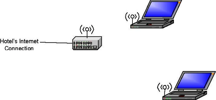
Note that the SMC WTK-G AP acts only as a layer 2 bridge and does not act as a
DHCP server. In other words, it does not supply dynamic IP addresses and instead relies
on the network to supply them.
Figure 1: AP Mode
Wireless Client
SMC WTK-G AP Mode Wireless Client
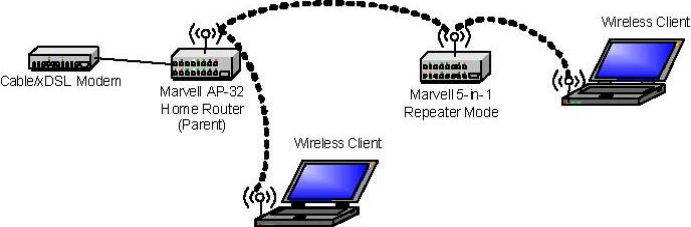
3.1.2 Repeater Mode
Repeater mode extends the range of a wireless network. Repeater nodes retransmit
the signal of an AP or wireless router to effectively extend the range of that AP or wireless
router. Wireless clients can associate with the repeater.
Figure2 shows the network with one repeater, and the repeater allowing wireless
clients to associate.
To configure the SMC WTK-G as a Repeater, please ensure the following:
. • Enter the MAC address of the Parent AP or wireless router in the Remote AP MAC address
field in the SMC WTK-G Repeater.
• Enter the MAC address of the SMC WTK-G (Repeater mode) in the Repeater MAC adddress
field in the Parent AP or wireless router.
Figure 2: One Wireless Repeater Node
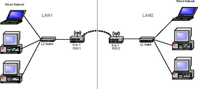
3.1.3 Point-to-Point (P2P) Mode
Two SMC WTK-G devices, each in Point-to-Point (P2P) mode, can establish a
wireless connection between two wired networks, as shown in Figure3. The two SMC
WTK-G devices operating in P2P mode do not allow client associations.
To configure the SMC WTK-G deivces to establish a P2P wireless bridge, please
ensure the following:
. • Enter the MAC address of SMC WTK-G P2P_2 device in the P2P MAC address field in the
SMC WTK-G P2P_1 device.
• Enter the MAC address of SMC WTK-G P2P_1 device in the P2P MAC address field in the
SMC WTK-G P2P_2 device.
Figure 3: P2P Wireless Bridge
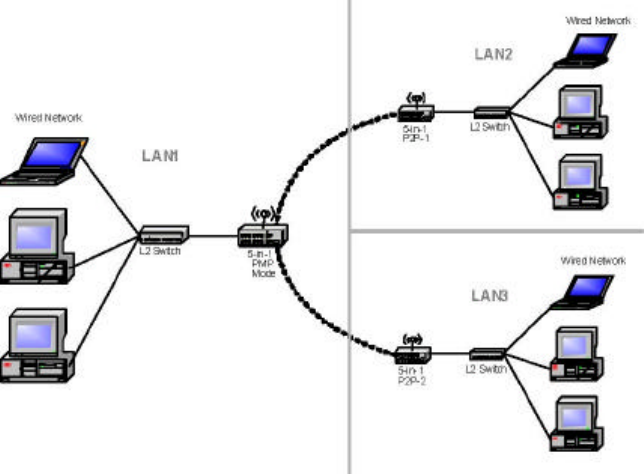
3.1.4 Point-to-Multipoint (PMP) Mode
A SMC WTK-G device operating in Point-to-Multipoint (PMP) mode can wirelessly
connect two or more wired networks, as shown in Figure4. The root SMC WTK-G device
(LAN 1) operates in PMP mode, and the other SMC WTK-G devices (LAN 2, LAN 3) must
operate in P2P mode.
When operating in PMP mode, the SMC WTK-G device does not allow client
associations. The user must enter the MAC addresses of each (up to six) SMC WTK-G P2P
device into the PMP system's table of Remote AP addresses.
Figure 4: PMP Wireless Bridge
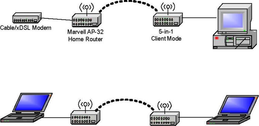
3.1.5 Client Mode
When set to Client mode, the SMC WTK-G device will associate to an AP within its
range in infrastructure mode, as shown in Figure5or join with another SMC WTK-G device in
Client mode in an ad-hoc network, as shown in Figure6. The Client behaves like a normal
wireless client.
Figure 5: Client in Infrastructure Mode
Figure 6: Client in Ad-Hoc Mode
SMC WTK-G SMC WTK-G Client Mode Client Mode

4. Wireless Security Support
The SMC WTK-G will support WEP encryption and WPA/PSK encryption as
shown in Table1.
Table 1: Wireless Security
Mode WEP WPA/PSK Comments
Access Point Yes Yes In AP mode, the WTK-G acts like a regular AP. Supports
WEP and WPA/PSK.
Repeater Yes No (for The link between the Repeater and wireless clients will
Repeater- support both WEP or WPA/PSK. However, the link
AP link) between the Repeater and the AP will support only WEP
Yes (for
Repeater-
in the initial release. Future releases will support WPA/
PSK.
Client link)
Point-to-Point Yes No The link between WTK-G devices in P2P and/or PMP
(P2P) mode support only WEP in the initial release. Future
releases will support WPA/PSK.
Point-to-Multipoint Yes No The link between WTK-G devices in P2P and/or PMP
(PMP) mode will support only WEP in the initial release. Future
releases will support WPA/PSK.
Client Yes Yes In Client mode, the WTK-G acts like a regular wireless
client, so it will support WEP and WPA/PSK when
connecting with an AP in infrastructure mode or WEP
when connecting to an Ad-Hoc network.
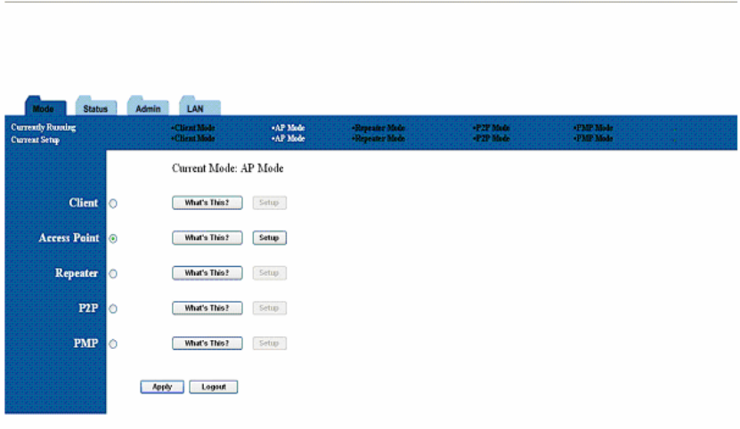
5. Mode Selection
The first step in using the SMC WTK-G is selecting the operating mode. The default operating mode is
the AP mode.
To view the device’s web page, go to 192.168.2.25 (default IP address of the device) in your web
browser. The default username is “admin” and the password is “smcadmin.”
To select a mode, click the Mode tab. Click the radio button next to the desired mode and click the Apply
button. The device will reboot in the selected mode. After the board reboots, click the Setup button to
begin configuring the device.
Figure 7:Mode Page
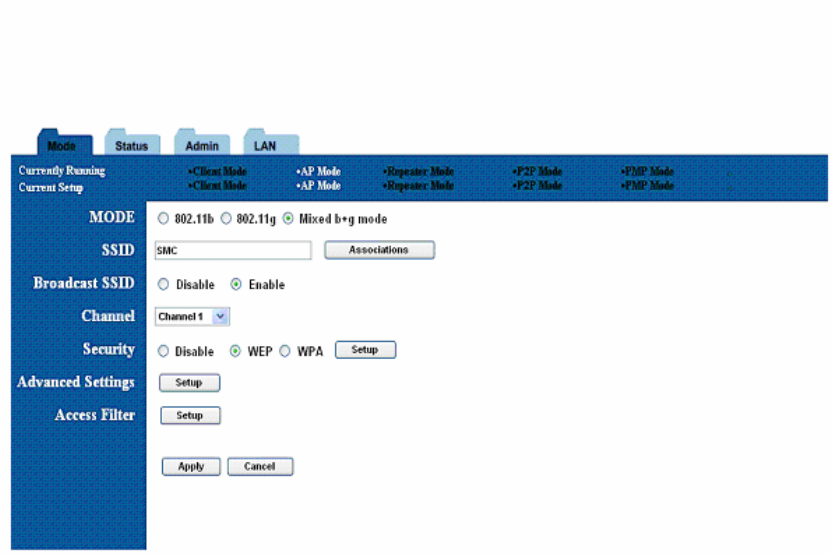
6. AP Setup
6.1 Basic Setup
To configure the AP, select AP from the Mode page and click Setup. The following table
shows the basic setup options.
Figure 8:AP Setup Page
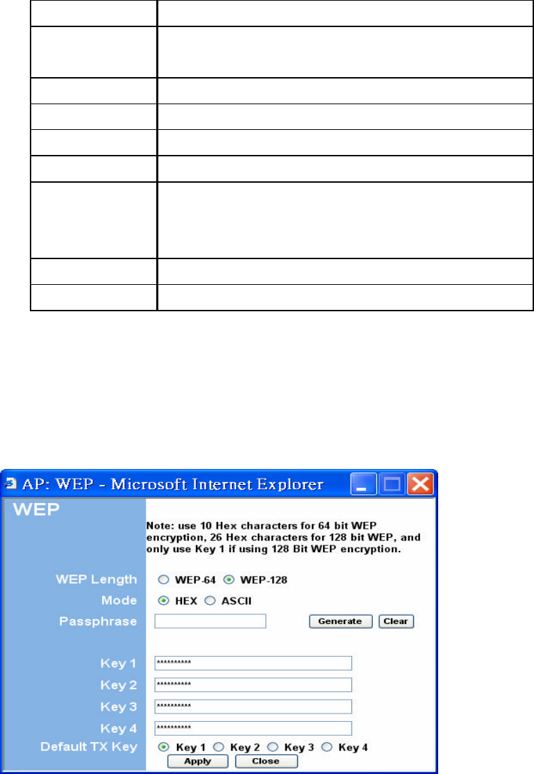
Table 2: AP Setup
Field Description
Mode Selects 802.11g/b mode:
802.11g only, 802.11b only, or Mixed
SSID Wireless Network Name
Association Wireless clients association table
SSID Broadcast Enable/disable the SSID broadcast feature.
RF Channel Selects the channel
Security Selects the option to disable security or to use WEP or WPA
security. If using WEP or WPA, click the Setup button to enter the
key(s).
Advanced Settings Click Setup to configure advanced settings.
Access Filter Click Setup to configure the access filter
6.2 Security Setup
To enable security, select the desired security mode (WEP or WPA) from the AP setup page
and click Setup to enter the keys.
Figure 9: WEP Configuratiom
The following tables describe the security setup options in more detail.
Table 3: WEP Setup
Field Description
WEP Length Selects the WEP key length
Mode Selects the WEP key format, ASCII or Hex
Passphrase Passphrase used to generate the WEP keys. Click the Generate
button to generate the keys.
Key 1-4 WEP keys
Default Tx key Selects the default WEP key (1-4)
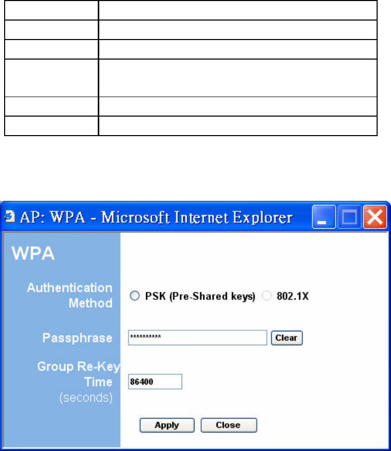
Figure 10: WPA Configuration
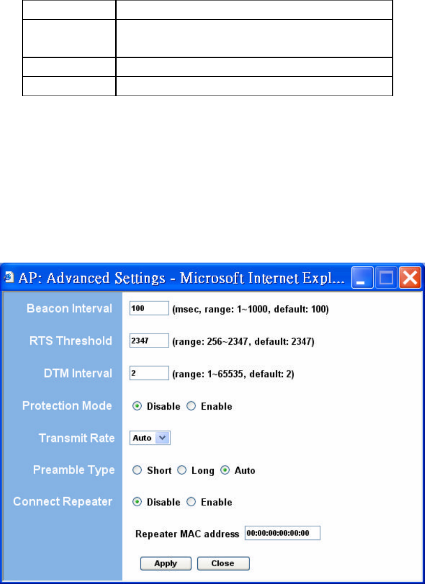
Table 4: WPA Setup
Field Description
Authentication Selects Pre-Shared Key (PSK) only.
Method
Passphrase WPA key
Group Re-Key Time
Group Re-Key interval (seconds)
6.3 Advanced Settings
The Advanced Settings page allows you to configure advanced Radio settings as well as
extend the SMC WTK-G (AP mode) range by wirelessly linking it to a SMC WTK-G (Repeater
mode).
Figure 11: Advanced Settings

The following table describes the setup
options in detail.
Table 5: AP Advanced Settings
Field Description
Beacon Interval Beacon interval (in milliseconds)
RTS Threshold RTS threshold (in bytes)
DTIM Interval DTIM interval
Protection Mode Allows user to force 802.11g protection (RTS/CTS) mode off.
Transmit Rate Selects the transmit rate: Auto or a fixed rate
Preamble Type Selects short preamble, long preamble, or Auto
Connect Repeater Enables/Disables the use of a Repeater
Repeater MAC MAC address of the Repeater, if used
Address
6.3.1 Adding a Repeater
If a Repeater is used along with the Access Point, go to the Advanced Settings
page. Select Enable for the “Connect Repeater” field. Enter the MAC address of the
Repeater in the “Repeater MAC address” field.
6.4 Access Filter
The Access Filter page allows you to configure the AP to allow or deny association to the AP
based on the client’s MAC address. Up to 32 MAC addresses can be added to the list.
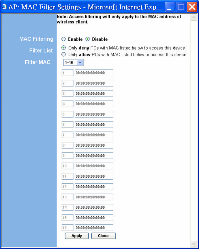
Figure 12: Access Filter Settings

The following table describes the setup options in detail.
Table 6: AP Access Filter Settings
Field Description
MAC filtering Enables/Disables MAC filtering mode
Filter List Provides the option to allow or deny clients with MAC addresses
listed
Filter MAC Up to 32 MAC addresses can be listed, but only 16 can be
viewed/modified at a time. This pulldown menu selects which
group of 16 to view/modify.
MAC addresses List of MAC addresses to filter
7. Repeater Setup
7.1 Basic Setup
To configure the Repeater, select Repeater from the Mode page and click Setup. The
following table shows the basic setup options
To set up the Repeater, you must enter the MAC address of the AP or AP/Router you
want to connect to the Repeater.
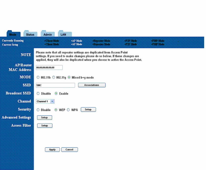
Figure 13: Repeater Setup

Table 7: Repeater Setup
Field Description
AP/Router MAC MAC address of AP/Router that this Repeater is connected to.
Address
Mode Selects 802.11g/b mode:
802.11g only, 802.11b only, or Mixed
SSID Broadcast Enable/disable the SSID broadcast feature.
Channel Selects the channel
Security Selects the option to disable security or to use WEP or WPA
security. If using WEP or WPA, click the Setup button to enter the
key(s).
Advanced Settings Click Setup to configure advanced settings.
Access Filter Click Setup to configure the access filter
7.2 Security Setup
To enable security, select the desired security mode (WEP or WPA) from the setup page and
click Setup to enter the keys. The following tables describe the security setup options in more
detail.
Table 8: WEP Setup
Field Description
WEP Length Selects the WEP key length
Mode Selects the WEP key format, ASCII or Hex
Passphrase Passphrase used to generate the WEP keys. Click the Generate
button to generate the keys.
Key 1-4 WEP keys
Default Tx key Selects the default WEP key (1-4)

Table 9: WPA Setup
Field Description
Authentication Selects Pre-Shared Key (PSK) or 802.1x mode
Method
Passphrase WPA key
Group Re-Key Time
Group Re-Key interval (seconds)
7.3 Advanced Settings
The Advanced Settings page allows you to configure advanced Radio settings. The following
table describes the setup options in detail.
Table 10: Repeater Advanced Settings Field
Field Description
Beacon Interval Beacon interval (in milliseconds)
RTS Threshold RTS threshold (in bytes)
DTIM Interval DTIM interval
Protection Mode Allows user to force 802.11g protection (RTS/CTS) mode off.
Transmit Rate Selects the transmit rate: Auto or a fixed rate
Preamble Type Selects short preamble, long preamble or Auto
7.4 Access Filter
The Access Filter page allows you to configure the Repeater to allow or deny assocation to
the Repeater based on the client’s MAC address. Up to 32 MAC addresses can be added to the list.
The following table describes the setup options in detail.

Table 11: Repeater Access Filter Settings
Field Description
MAC filtering Enables/Disables MAC filtering mode
Filter List Provides the option to allow or deny clients with MAC addresses
listed
Filter MAC Up to 32 MAC addresses can be listed, but only 16 can be
viewed/modified at a time. This pulldown menu selects which
group of 16 to view/modify.
MAC addresses List of MAC addresses to filter
8. Point-to-Point (P2P) Setup
8.1 Basic Setup
To configure the P2P Bridge, select P2P from the Mode page and click Setup. The following
table shows the basic setup options.
To set up the P2P bridge, you must enter the MAC address of the other P2P bridge you
want to connect to this P2P bridge.
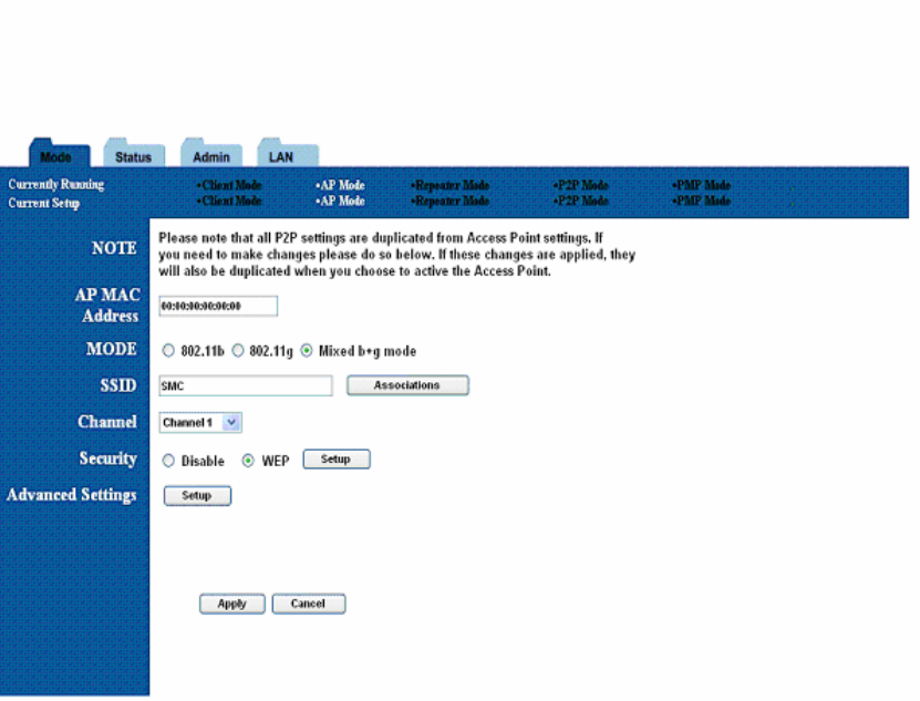
Figure 14: P2P Setup
8.2 Security Setup
To enable security, select WEP from the setup page and click Setup to enter the keys. The

following tables describe the security setup options in more detail.
Table 13: WEP Setup
Field Description
WEP Length Selects the WEP key length
Mode Selects the WEP key format, ASCII or Hex
Passphrase Passphrase used to generate the WEP keys. Click the Generate
button to generate the keys.
Key 1-4 WEP keys
Default Tx key Selects the default WEP key (1-4)
8.3 Advanced Settings
The Advanced Settings page allows you to configure advanced Radio settings. The following
table describes the setup options in detail.
Table 14: P2P Advanced Settings
Field Description
RTS Threshold RTS threshold (in bytes)
DTIM Interval DTIM interval
Protection Mode Allows user to force 802.11g protection (RTS/CTS) mode off.
Transmit Rate Selects the transmit rate: Auto or a fixed rate
Preamble Type Selects short preamble, long preamble or Auto
9. Point-to-Multipoint (PMP) Setup
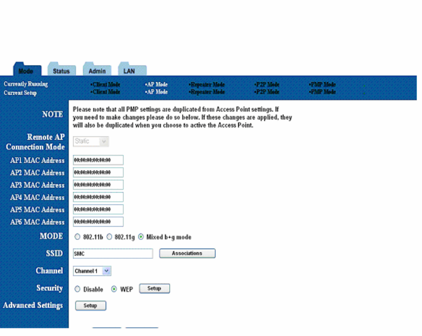
9.1 Basic Setup
To configure the PMP Bridge, select PMP from the Mode page and click Setup. The
following table shows the basic setup options
To set up the PMP bridge, you must enter the MAC address(es) of the P2P bridge(s) you
want to connect to this PMP bridge.
Figure 15: PMP Setup

Table 15: PMP Setup
Field Description
AP MAC Address MAC address(es) of the P2P bridges that are connected to this
(1-6) PMP bridge
Mode Selects 802.11g/b mode:
802.11g only, 802.11b only, or Mixed
Channel Selects the channel
Security Selects the option to disable security or to use WEP security. If
using WEP, click the Setup button to enter the key(s).
Advanced Settings Click Setup to configure advanced settings.
9.2 Security Setup
To enable security, select WEP from the setup page and click Setup to enter the keys. The
following tables describe the security setup options in more detail.
Table 16: WEP Setup
Field Description
WEP Length Selects the WEP key length
Mode Selects the WEP key format, ASCII or Hex
Passphrase Passphrase used to generate the WEP keys. Click the Generate
button to generate the keys.
Key 1-4 WEP keys
Default Tx key Selects the default WEP key (1-4)
9.3 Advanced Settings
The Advanced Settings page allows you to configure advanced Radio settings. The following
table describes the setup options in detail.
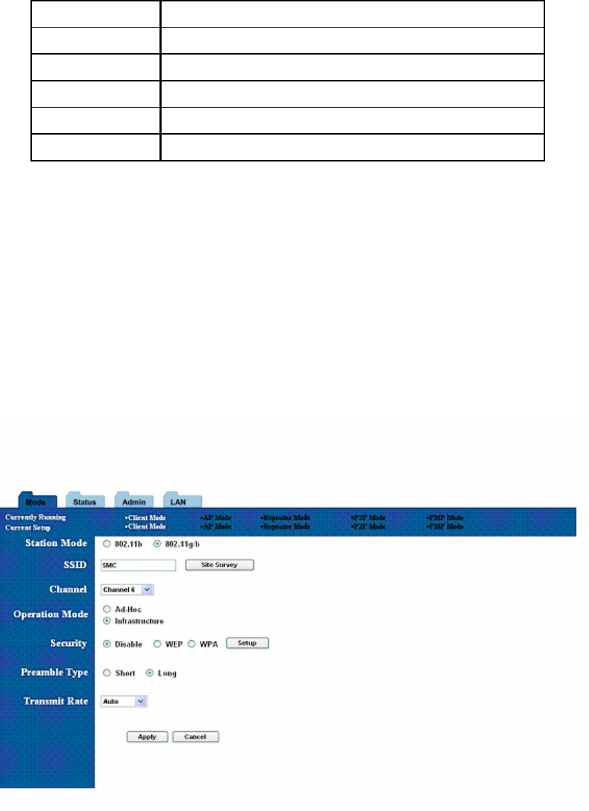
Table 17: PMP Advanced Settings
Field Description
RTS Threshold RTS threshold (in bytes)
DTIM Interval DTIM interval
Protection Mode Allows user to force 802.11g protection (RTS/CTS) mode off.
Transmit Rate Selects the transmit rate: Auto or a fixed rate
Preamble Type Selects short preamble, long preamble or Auto
10. Client Mode Setup
10.1 Basic Setup
To configure the Client, select Client from the Mode page and click Setup. The following
table shows the basic setup options.
Figure 16: Client Bridge Setup

Field Description
Station Mode Selects 802.11g/b mode:
802.11b only or 802.11g/b
SSID Wireless Network Name. You can enter it directly in this field or
click the Site Survey button to select from a list of available
networks.
Table 18: AP Setup (Continued)
Field Description
Channel Selects the channel (Ad-Hoc network only)
Operation Mode Selects Ad-Hoc or Infrastructure mode
Security Selects the option to disable security or to use WEP or WPA
security. If using WEP or WPA, click the Setup button to enter the
key(s).
Preamble Type Selects short or long preamble
Transmit Rate Selects the transmit rate: a fixed rate or Auto
10.2 MAC Cloning
To enable MAC cloning mode, go to the MAC Cloning field on the LAN page and select
Enabled. MAC cloning clones all the MAC addresses of the devices connected to the ethernet
(wired) port to a single MAC address sent out wirelessly to an AP or Repeater.
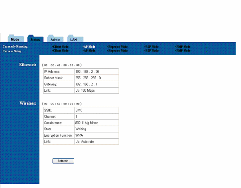
11. Status Page
The status page reports relevant status information for the device, for both the ethernet and
wireless interfaces.
Figure 17: Status Page
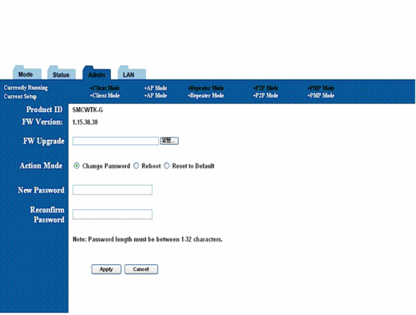
12. Admin Page
The admin page lets you upgrade the device’s firmware or change
the password.
Figure 18: Admin Page
12.1 Firmware Upgrade
To upgrade the firmware, click the Browse button and select the image file. Click Apply to
upgrade.
12.2 Update Password
To change the password, enter the new password in the New Password and Reconfirm
Password fields and click Apply.
12.3 Reboot
To reboot, check the reboot radio and click Apply.
12.4 Reset to Default Setting
To reboot, check the reset to default radio and click Apply.
13. LAN Page
The LAN page lets you set the device’s IP address. The device can be configured to use an
automatic (DHCP) address or a fixed IP address.
The default IP address is 192.168.2.25.
When the device is in Client mode, the LAN page also provides the MAC cloning option.
It is important that before you configure the SMC WTK-G device (regardless of the mode it is in) to
Automatic IP, you should know how to determine the SMC WTK-G device’s IP address from the
device it is connected to.
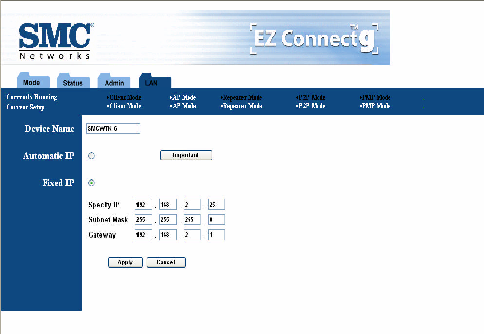
Figure 19: LAN Page
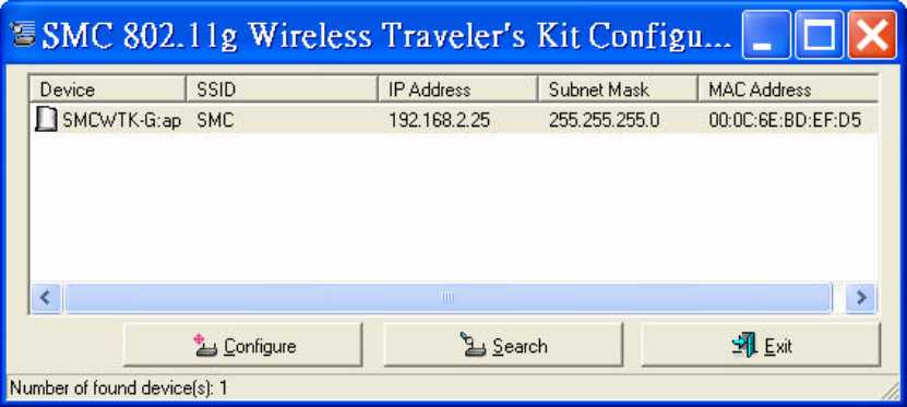
14. Utility
14.1 Configuration Utility
The Configuration utility is a disvocovery tool for an SMC WTK-G. This utility is available in
the support CD that came with the SMC WTK-G package. Use the Configuration utility to find and
condfig a SMC WTK-G near you.
Figure 20: Configuration Utility
14.2 Firmware Restoration
The Firmware Restoration utility is a rescue tool for an SMC WTK-G that failed during a
previous firmware upload. This utility is available in the support CD that came with the SMC
WTK-G package. A failed firmware upgrade causes the ASUS Pocket Wireless AP to enter a
failure mode. Use the Firmware Restoration utility to find and upload a new firmware for the SMC
WTK-G.
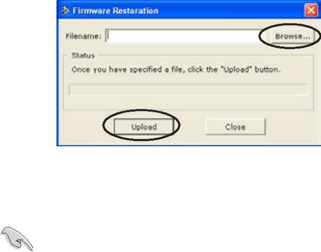
To restore the firmware:
1. Visit the SMC website to download the latest firmware for the device.
2. Launch the Firmware Restoration utility from the Windows® desktop by clicking Start > All
Programs > SMC 802.11g Wireless Traveler’s Kit > Firmware Restoration.
3. The Firmware Restoration window appears.
4. Click the Browse button to locate the firmware file.
5. After selecting the firmware file, click the Upload button to begin the firmware restoration.
Figure 21: Rescue Utility
The restoration process takes about 3 to 4 minutes to finish. During restoration, the Power,
and Wireless LEDs remain lit, while the Ethernet LED flashes slowly.
If you have problems uploading a firmware while using a network hub, try connecting your
computer directly to the LAN port.
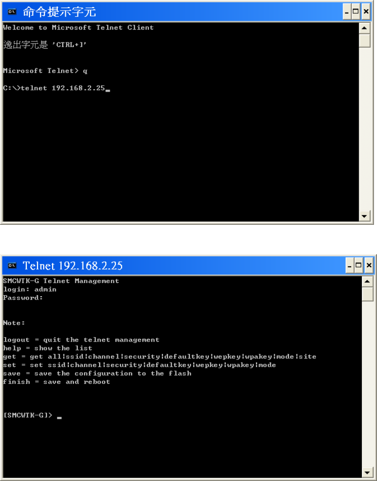
15. Telnet Management
15.1 telnet step by step
Step1: telnet to SMCWTK-G
Step2: fill in the login information.
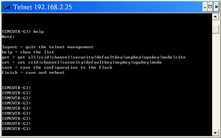
Step3: type help for HELP.
Step4: type command by command reference table.
Table 19: Command Reference Table

Type Command Format Example
Get all Get all
Get ssid Get ssid
Get channel Get channel
Get security Get security
Get defaultkey Get defaultkey
Get wepkey Get wepkey
Get wpakey Get wpakey
Get mode Get mode
Get command
Get site Get site
Set ssid Set ssid MYSMC_AP0 (SSID: “MYSMC_AP0”)
Set Channel Set channel 12 (Channel: 12)
Set Security Set Security 0 (0 is for Disable)
Set defaultkey Set defaultkey 1 (Default WEP Key: 1)
Set wepkey Set wepkey 1 1234567890 (Wepkey1: 1234567890)
Set wpakey Set wpakey smcisgood! (Wepkey: “smcisgood!”)
Set command
Set mode Set mode 2 (SMCWTK-G change to Repeater mode)
Logout Quit the telnet management.
Save Save the configuration to the flash
Other command
Finish Save and reboot

APPENDIX
Federal Communications Commission Statement
This device complies with Part 15 of the FCC Rules. Operation is subject to the following two
conditions:
(1) this device may not cause harmful interference, and
(2) this device must accept any interference received, including interference that may cause
undesired operation.
This manufacture is not responsible for any radio or TV interference caused by unauthorized
modification to this equipment. Such modification could void the user’s authority to operate the
equipment.
This device and its antenna(s) must not be co-located or operating in conjunction with any
other antenna or transmitter.
To maintain compliance with FCC’s RF exposure guidelines, this equipment should be installed
and operated with minimum distance 20cm between the radiator and your body. Use on the
supplied antenna.
Declaration of Conformity for R&TTE directive 1999/5/EC
Essential requirements – Article 3
Protection requirements for health and safety – Article 3.1a
Testing for electric safety according to EN 60950 has been conducted. These are considered relevant
and sufficient.
Protection requirements for electromagnetic compatibility – Article 3.1b
Testing for electromagnetic compatibility according to EN 301 489-1 and EN 301 489-17 has been
conducted. These are considered relevant and sufficient.
Effective use of the radio spectrum – Article 3.2
Testing for radio test suites according to EN 300 328-2 has been conducted. These are considered
relevant and sufficient.