ATBS Technology SC-BT6800 TPMS for iPod,iPhone,iPad User Manual
ATBS Technology Co. TPMS for iPod,iPhone,iPad
User manual
Copyright (C) ATBS Technology Co. R1
版權所有請勿翻印
iTPMSystem for iPod, iPhone, iPad User’s Guide
1. Introduction
This Tire Pressure Monitoring System (TPMS) was
designed for increasing security, reliability, and
understanding on tire conditions of your car. Once you
properly install the TPMS, these sensors will
automatically monitor pressures and temperatures of tires
in real time, and send these data to Receiver through
Bluetooth communications. When any abnormal pressure
(under or over inflated) and/or temperature of tire is
detected, iPhone, iPod, and iPad will alert driver by its
LED warning signal and sound alarm immediately.
This system could ensure you are driving in safety.
About This Manual
The information in this manual is subject to change
without notice.
This manual has been created with carefulness. In
case that you have any comments or questions
regarding this manual, please contact your local
dealer or our Customer Service Center.
Before operating this set, please fully understand
the prerequisite such as specifications or
constraints of the hardware and software. We are
not responsible and have no liability for any loss,
damage or injury as a result of misuse.
2. Check Accessories
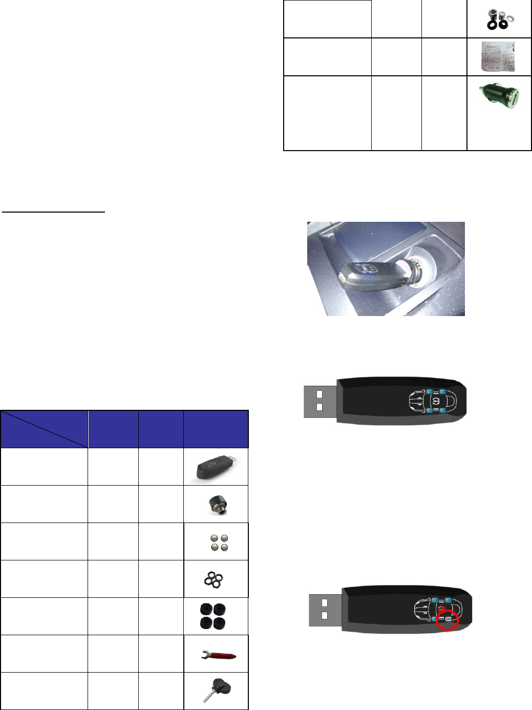
BT6800
(AT67)
BT6800
(MS30)
receiver
1
1
AT 67 sensor
4
0
AT67 battery
4
0
Lock nut
4
0
Rubber gasket
4
0
Wrench
1
0
MS30 sensor
0
4
MS30 accessories
0
4
User guide
1
1
Power adaptor
(12V to 5V)
1
1
3. System Installation
3.1 Install Receiver :
3.1.1 Plug in power adaptor.
3.1.2 Plug USB connector into power adaptor.
3.1.3 Receiver will display Blue LED to each wheel
position. The LED blue light of receiver will light up
once it gets the sensor’s signal.
3.1.4 However, if L2 wheel is abnormal, the L2 blue light
will flash and the yellow warning signal in the middle
will light up.
(1) If the tire pressure is too low: it’ll alert with a
short sound.
(2) If the tire pressure is too high: it’ll alert with a
long sound and a short sound.
(3) If the tire temperature is too high: it’ll alert with
continuous long sound.
3.1.5 And if the receiver can’t get the signal from R1
sensor, the LED blue light of R1 will go out, then please
check as follows:
(1) replace the sensor’s battery.
(2) go to App to confirm whether the ID position is
correct.
Copyright (C) ATBS Technology Co. R1
版權所有請勿翻印
(3) to check whether the installation is correct.
Note: The mini USB socket in the back is for power only,
there’s no data communication function.
3.2 Install A-Type External Sensor (Battery
replaceable):
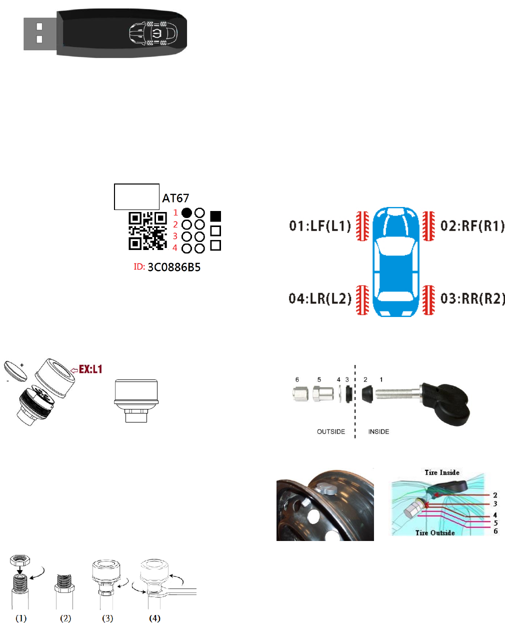
3.2.1 Each sensor’s label has been marked its ID and its
wheel order.
EX:
Sensor’s Model. No.:
AT67
Wheel Order: 01:L1
ID: 3C0886B5
3.2.2 Place the battery into the sensor and screw the top
cap onto the sensor. Please follow the battery’s polarity to
place the battery. Upside is +, downside is -.
3.2.2 Remove the original valve cap from the tire.
3.2.3 Screw lock nut first (1) and will become (2). Screw
the sensor onto valve stem clockwise (3). Screw (1)
lock nut back and use the wrench to lock tightly (4).
(3)(4) steps can make sure the sensor’s fixity and is
provided with anti-theft function.
Note
:
(1) Beware of the conductivity between the sensor
and the valve stem.
(2) Sensors are supposed to be well locked onto the
valve stem to avoid from leaking.
(3) Please replace sensor’s battery once its voltage
is under 2.6v.
(4) If driver drives on a lumpy road, or the tire
pressure changes rapidly, our device will deem
this as a danger situation, and the device will
alert the driver continuously by sending 10
data, in this condition, the battery will ran out
fast.
3.3 Install M-Type Internal Sensor :
3.3.1 Each sensor’s label has been marked its ID
and its wheel order.
3.3.2 Tire location
3.4 Install Internal Sensor (M-type)
3.4.1 Remove the tires from vehicles.
3.4.2 Deflate the tires and detach rim and tire.
3.4.3 Install sensor on rim to appropriate position.
3.4.4 Balance wheels.
3.4.5 Install wheel to appropriate position.
4. iTPMS APP Installation:
iTPMS App is for free. Through the App, you can know tire
temperature and pressure, battery voltage of each sensor,
and each sensor’s ID.
01: Left Front (L1) 02: Right Front (R1)
04: Left Rear (L2) 03: Right Rear (R2)
Model
Copyright (C) ATBS Technology Co. R1
版權所有請勿翻印
4.1 Install App
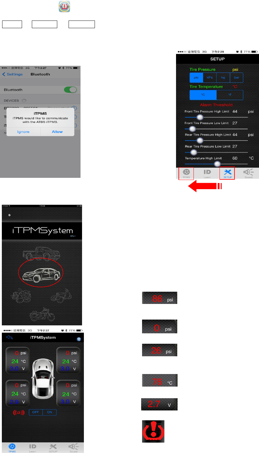
4.1-1 Download the APP: iTPMS from Apple Store/
Google Play.
4.1-2 Go to Setting General Bluetooth Page.
4.1-3 Turn on the Bluetooth, and search the device.
4.1-4 Find iTPMS device and pair with it. The name of
device is BT6800 XXXXXX (X=0-9)
4.1-5 Click Allow to start iTPMS APP.
4.1-5 Choose the vehicle and then user is allowed to read
tire condition from the App.
Note: Four sensors was set by the manufacturer, there’s
no need to pair the sensors again. (If there are requests to
change new sensors or to change the wheel order please
follow the instruction: sensor ID learning.)
4.2 iTPMSystem alert and setting instruction:
4.2-1 Enter Setup page, users can set up the unit and limit
of tire pressure and temperature.
Go back to main page to save the setting.
After finishing the setting and go back to main page, the
receiver will flash 1 time, it means the setting is already
saved into the receiver. When downloading a new iTPMS,
make sure to set up the unit, tire pressure and tire
temperature limit, and go back to main page and save it.
4.2-2 iTPMSystem App alert description:
Go to the setting page and users are allowed to set tire
pressure and temperature limit. (Please refer to the
vehicle’s tire pressure label, we suggest to set the lower
limit to 80% of the normal value.)
Tire pressure is too high and it’s over the
limit.
No pressure.
Tire pressure is too low and it’s under the
limit.
Tire temperature is over the limit.
Sensor’s battery voltage is too low.
Tire condition is abnormal.
Copyright (C) ATBS Technology Co. R1
版權所有請勿翻印
4.3 Reset Sensor’s ID
4.3.1 Method 1:
External type: intall the sensor from the left front tire.
Internal type: First, deflate all tire pressure to 15psi, then
inflate the left front tire from the beginning.
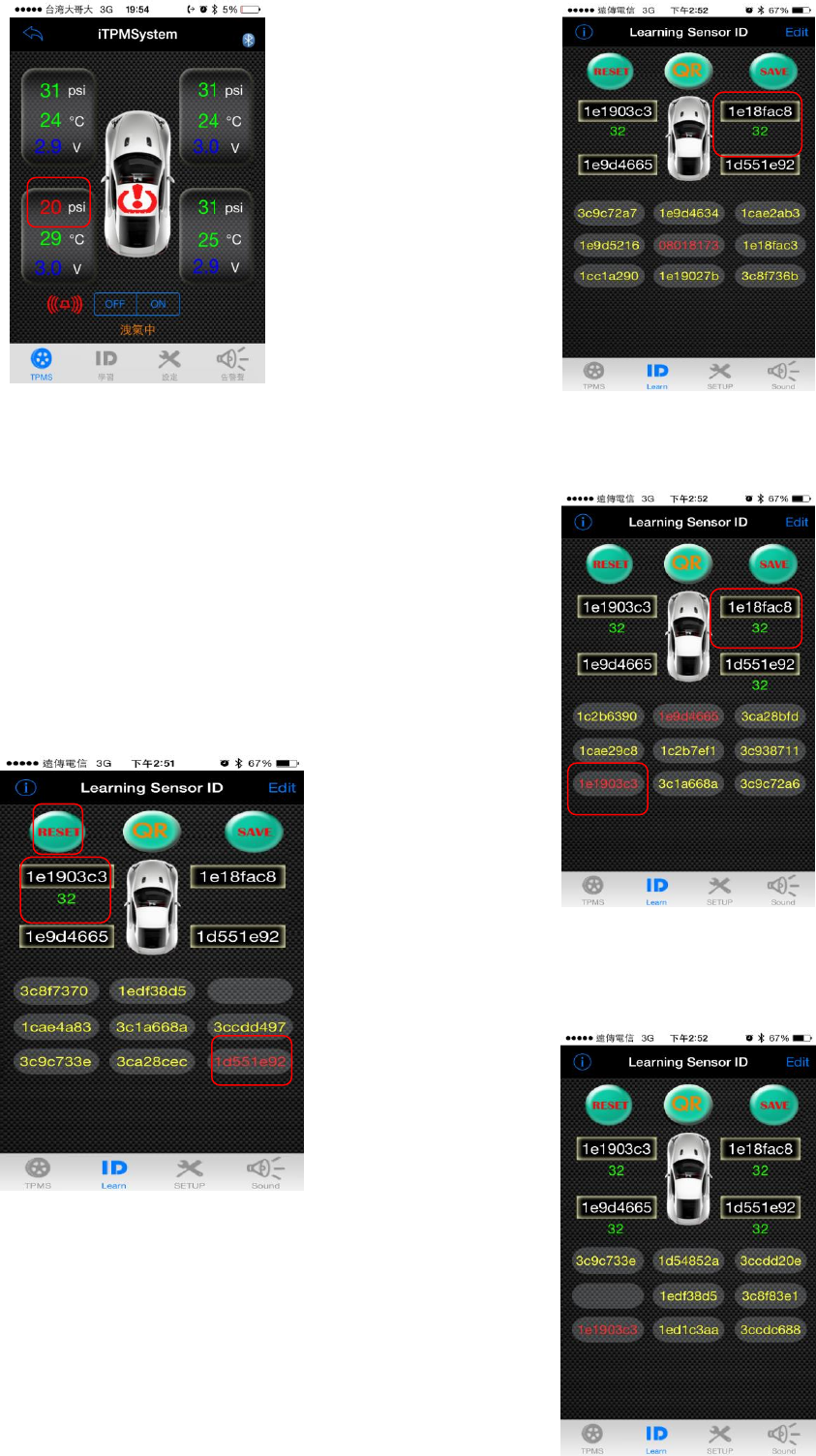
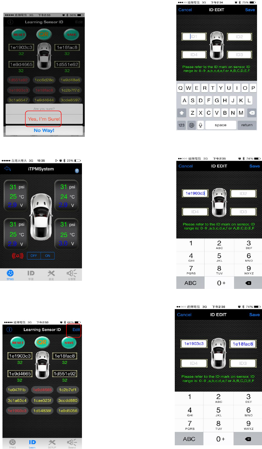
Step 1. Click the RESET button and when the left front
tire detects the tire pressure is over 20psi, the ID will turn
to red→click the red ID, and it’ll jump to the left front
wheel.
Step 2. When the right front tire detects the tire pressure
is over 20psi, the ID will turn to red→click the red ID, and
it’ll jump to the right front wheel.
Step 3. When the right rear tire detects the tire pressure is
over 20psi, the ID will turn to red→click the red ID, and it’ll
jump to the right rear wheel.
Step 4. When the left rear tire detects the tire pressure is
over 20psi, the ID will turn to red→click the red ID, and
it’ll jump to the left rear wheel.
Copyright (C) ATBS Technology Co. R1
版權所有請勿翻印
Step 5. Click SAVE and click YES to save, the receiver
will flash 1 time and it means the ID is saved into the
receiver.
Step 6. Go back to TPMS page to see the tire condition,
and it’s done.
4.3.2 Method 2: (this method is suitable for changing the
wheel order.)
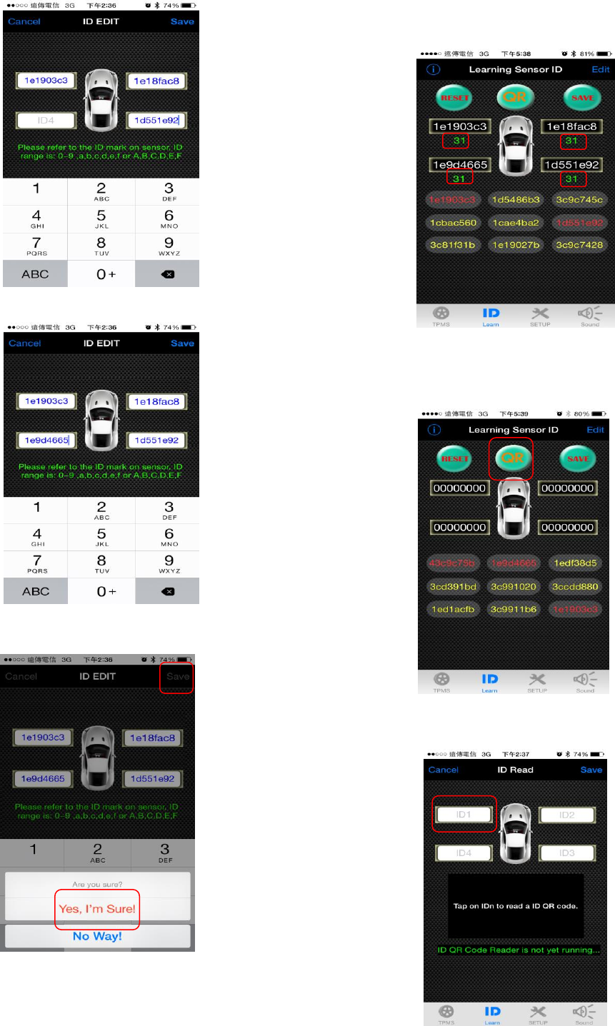
Step 1. Note down each wheel order’s ID anc click EDIT.
Step 2. Enter into edit page and click the blank and enter
the ID.
Step 3. (No need to follow the following order to enter the
ID) Enter the left front wheel’s ID.
Step 4. Enter the right front wheel’s ID.
Copyright (C) ATBS Technology Co. R1
版權所有請勿翻印
Step 5. Enter the right rear wheel’s ID.
Step 6. Enter the left rear wheel’s ID.
Step 7. After entering all sensor’s ID, click SAVE and click
YES.
Step 8. Go back to ID Learning page, when it shows
green values (tire pressure condition) under the ID, click
SAVE and click YES to save it, the receiver will flash 1
time, it means the ID is saved into the receiver.
Go back to TPMS page to see the tire condition, and it’s
done.
4.3.3 Method 3: (this method is suitable for changing the
wheel order.)
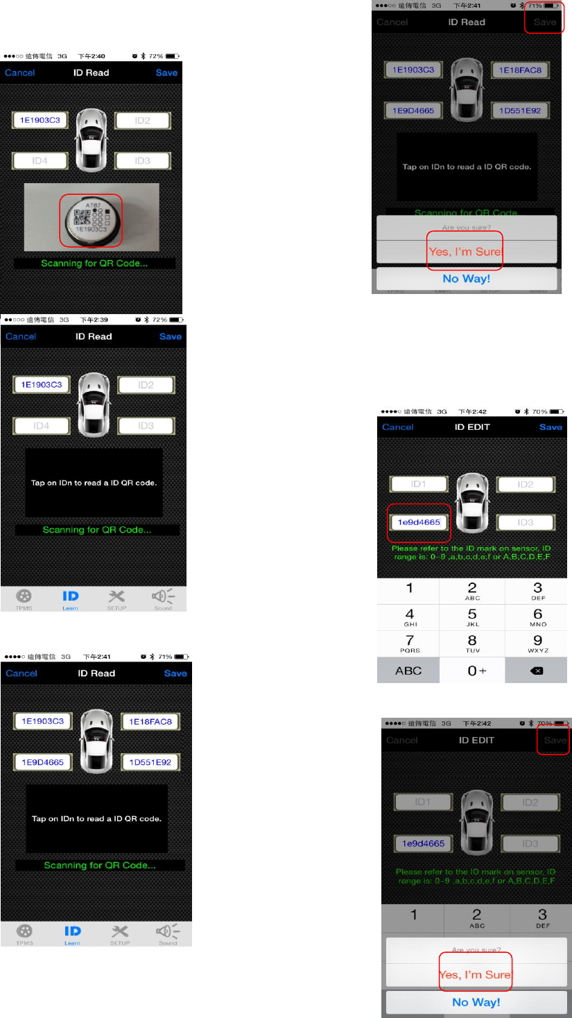
Step 1. Go to ID Learnig page and click QR.
Step 2. Enter into ID Read page, and click the blank to
start scanning QR code.
Copyright (C) ATBS Technology Co. R1
版權所有請勿翻印
Step 3. (No need to follow the following order to enter the
ID) Scan the left front wheel’s ID.
Step 4. Follow the above procedure and finish setting all
IDs.
Step 5. After entering all sensor’s ID, click SAVE and click
YES.
4.4 Individual Sensor ID Learning:
(Follow the following steps when changing a new
sensor.)
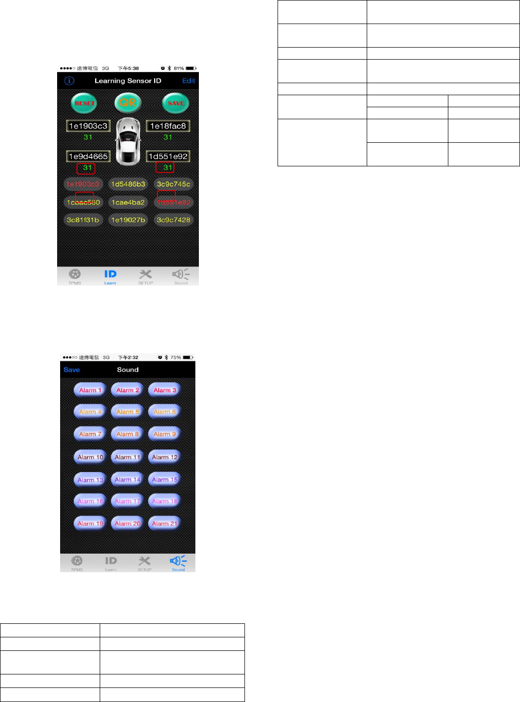
4.4.1 Enter the new sensor ID.
4.4.2 After entering the ID, click SAVE and click YES.
Copyright (C) ATBS Technology Co. R1
版權所有請勿翻印
4.4.3 Go back to ID Learning page, when it shows green
values (tire pressure condition) under the ID, click SAVE
and click YES to save it, the receiver will flash 1 time, it
means the ID is saved into the receiver. Go back to TPMS
page to see the tire condition, and it’s done.
4.5 Alarm Sound Setting:
Users can set their individual alarm sound by clicking the
button and save it. While the tire condition is abnormal, it’ll
sound the alarm.
5. Specification
5.1 BT6800 receiver:
Operation Voltage
USB 5V
Operation Current
80 mA
Operation
Temperature
-10~ 70 ℃
TPMS Frequency
433.92 MHz
BT Frequency
3.0SPP
5.2 Sensor (AT67 & MS30):
Operation
Temperature
-40 °C to 125 ± 1°C
Operating
Humidity
100%
Frequency
433.92MHz
Monitoring
Pressure
0~131± 1 psi
Battery
2.9V ± 0.1V
Weight
AT67
9.0g ± 0.2g
MS30
27g ± 0.5g
Battery Lifespan
AT67 (battery
exchangeable)
About 8~12
months
MS30
About 5
years
6. Caution:
6.1 Information provided in user’s guide is for reference
only. You should operate the device only when your
vehicle stops.
6.2 This product may be interrupted by some harmful
system and may lead to malfunction.
6.3 In order to install internal sensor properly, users are
suggested to body shop for assistance. Please beware of
the location of each sensor. Do not beat the valve directly
or use any tools to harm the valve.
6.4 Four sensors’ IDs of this product have already set by
the manufacturer. If you would like to replace new
sensors, please seek the agent for assistance.
6.4 Do not soak our product or sensor in the water or
chemical. Chemicals are not allowed to clean.
6.5 Do not use water or chemicals to clean or soak the
receiver and sensors directly.
6.6 Do not replace the rubber gasket arbitrarily. If there is
any damage, please replace it with the certified one.
6.7 The warranty of the product is one year, please use
the product correctly. The warranty excludes natural and
artificial disasters, drops, soaking in water accident, fire
accident, anomalistic power supply and other damages.
6.8 The warranty won’t cover any consumptive
accessories like: the packaging, Velcro, manual, etc.
6.9 Please refer to the steps from user’s guide to avoid
any abnormal operation. It may lead to malfunction.
6.10 Any changes or modifications in construction of this
device which are not expressly approved by the party
responsible for compliance could void the user’s authority

Copyright (C) ATBS Technology Co. R1
版權所有請勿翻印
to operate the equipment.
6.11 Please follow the instruction of power supply. Wrong
process of power supply will cause malfunction. Please
use the certified battery. Improper battery or wrong
procedures will affect efficiency or cause malfunction of
sensors.
6.12 Please observe tire pressure, temperature and
battery voltage at all times. If the receiver cannot get the
information for a long time, please check your sensors.
6.13 FCC Notice
This device complies with Part 15 of the FCC
Rules. Operation is subject to the following two conditions
(1) the device may not cause harmful interference, and (2)
this device must accept any interference received,
including interference that may cause undesired
operation. This equipment has been tested and found to
comply with the limits for a Class B digital device,
pursuant to Part 15 of the FCC Rules. These limits are
designed to provide reasonable protection against
harmful interference in a residential installation. This
equipment generates, uses and can radiate radio
frequency energy and, if not installed and used in
accordance with the instructions, may cause harmful
interference to radio communications. However, there is
no guarantee that interference will not occur in a
particular installation. If this equipment does cause
harmful interference to radio or television reception, which
can be determined by turning the equipment off and on,
the user is encouraged to try to correct the interference by
one or more of the following measures:
Increase the separation between the equipment and
receiver.
Change the receiver’s location and the way it connects.
Consult the dealer or an experienced radio/TV
technician for help.
Notice: Any modifications or any system
alterations cannot guarantee the user’s rights is
protected continuously.