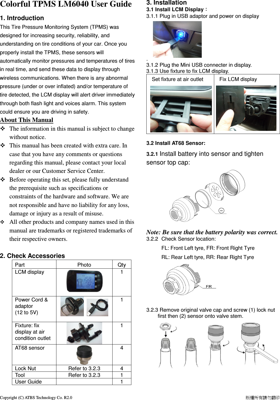
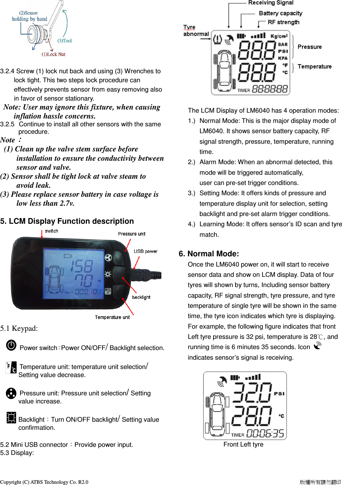
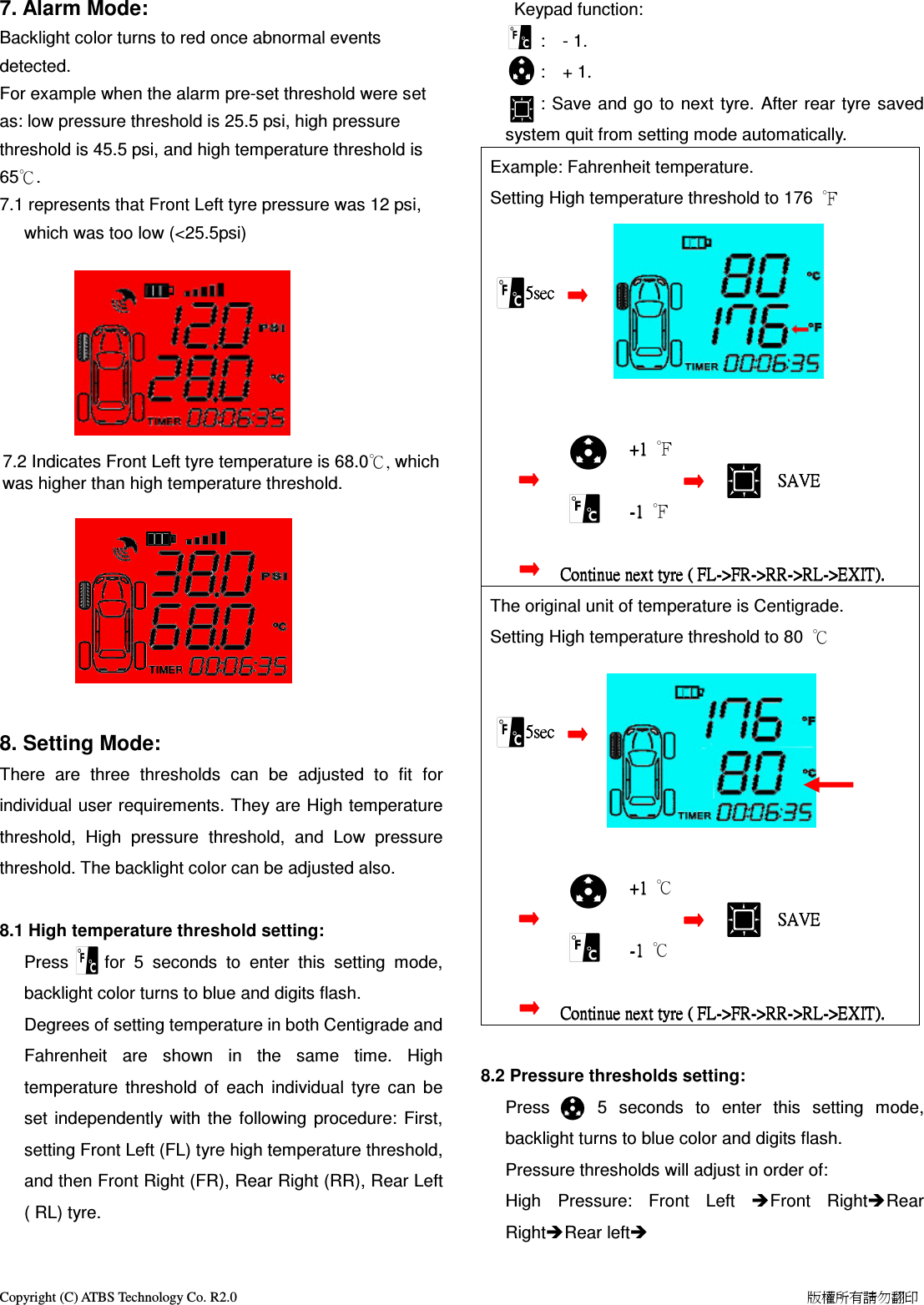
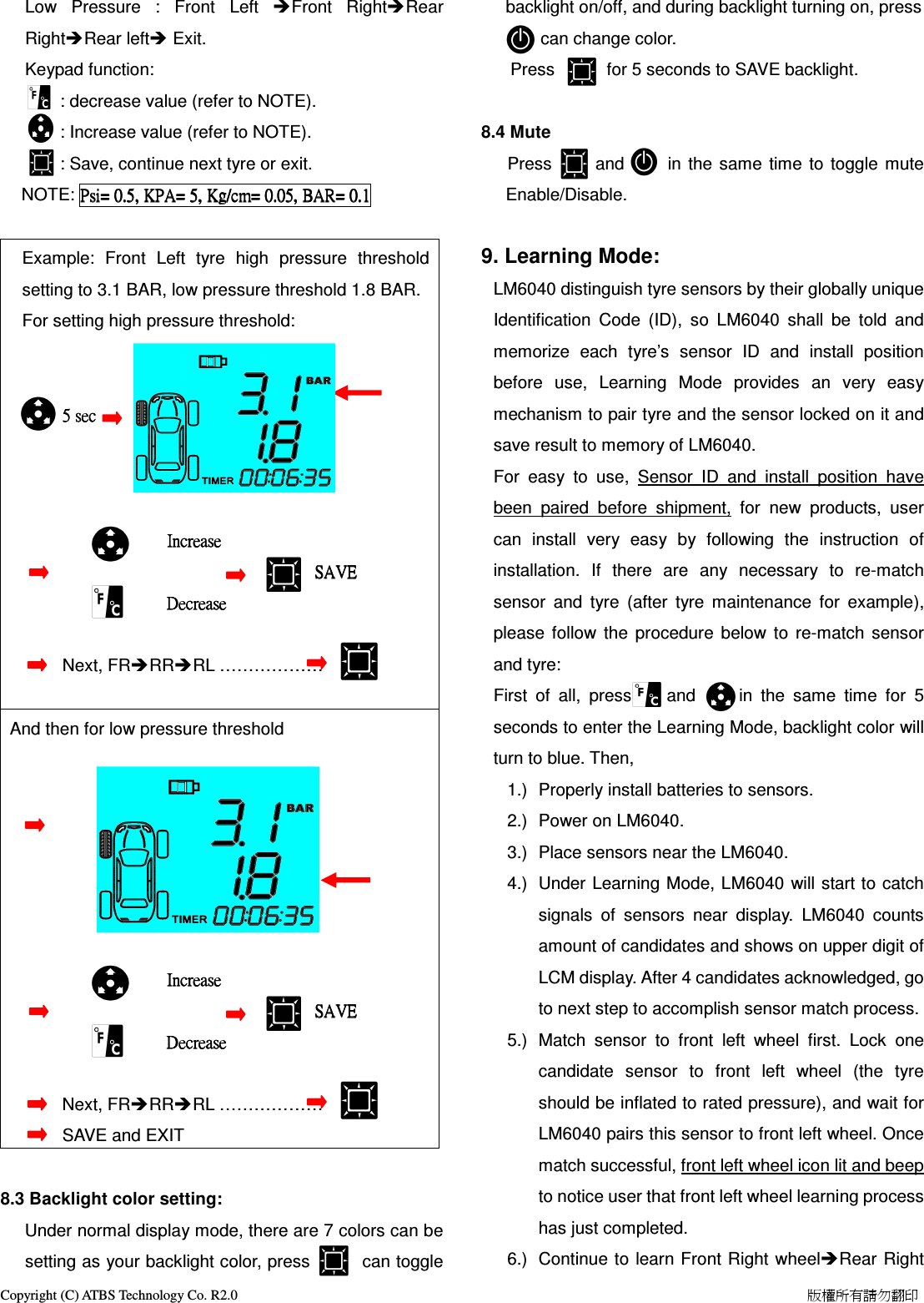
ATBS Technology SC-LM6040 CAR TPMS (Tire Pressure Monitoring System) User Manual LM6040 User Guide R3

ATBS Technology Co. CAR TPMS (Tire Pressure Monitoring System) LM6040 User Guide R3

Manual r1

Copyright (C) ATBS Technology Co. R2.0                                                                                                                                                                    版權所有請勿翻印   Colorful TPMS LM6040 User Guide   1. Introduction This Tire Pressure Monitoring System (TPMS) was designed for increasing security, reliability, and understanding on tire conditions of your car. Once you properly install the TPMS, these sensors will automatically monitor pressures and temperatures of tires in real time, and send these data to display through wireless communications. When there is any abnormal pressure (under or over inflated) and/or temperature of tire detected, the LCM display will alert driver immediately through both flash light and voices alarm. This system could ensure you are driving in safety.  About This Manual    The information in this manual is subject to change without notice.    This manual has been created with extra care. In case that you have any comments or questions regarding this manual, please contact your local dealer or our Customer Service Center.  Before operating this set, please fully understand the prerequisite such as specifications or constraints of the hardware and software. We are not responsible and have no liability for any loss, damage or injury as a result of misuse.  All other products and company names used in this manual are trademarks or registered trademarks of their respective owners.  2. Check Accessories Part  Photo  Qty LCM display    1 Power Cord & adaptor (12 to 5V)   1    Fixture: fix display at air condition outlet   1 AT68 sensor  4 Lock Nut  Refer to 3.2.3  4 Tool  Refer to 3.2.3  1 User Guide    1  3. Installation   3.1 Install LCM Display:::: 3.1.1 Plug in USB adaptor and power on display       .   3.1.2 Plug the Mini USB connecter in display. 3.1.3 Use fixture to fix LCM display.   Set fixture at air outlet         Fix LCM display   3.2 Install AT68 Sensor: 3.2.1 Install battery into sensor and tighten sensor top cap:       Note: Be sure that the battery polarity was correct. 3.2.2  Check Sensor location:   FL: Front Left tyre, FR: Front Right Tyre   RL: Rear Left tyre, RR: Rear Right Tyre         3.2.3 Remove original valve cap and screw (1) lock nut first then (2) sensor onto valve stem.
Copyright (C) ATBS Technology Co. R2.0                                                                                                                                                                    版權所有請勿翻印      3.2.4 Screw (1) lock nut back and using (3) Wrenches to lock tight. This two steps lock procedure can effectively prevents sensor from easy removing also in favor of sensor stationary.  Note: User may ignore this fixture, when causing inflation hassle concerns.   3.2.5   Continue to install all other sensors with the same procedure.  Note::::   (1) Clean up the valve stem surface before installation to ensure the conductivity between sensor and valve. (2) Sensor shall be tight lock at valve steam to avoid leak. (3) Please replace sensor battery in case voltage is low less than 2.7v.  5. LCM Display Function description            5.1 Keypad:              Power switch:Power ON/OFF/ Backlight selection.                      Temperature unit: temperature unit selection/ Setting value decrease.                                  Pressure unit: Pressure unit selection/ Setting value increase.  Backlight:Turn ON/OFF backlight/ Setting value confirmation.  5.2 Mini USB connector:Provide power input. 5.3 Display:   The LCM Display of LM6040 has 4 operation modes: 1.)  Normal Mode: This is the major display mode of LM6040. It shows sensor battery capacity, RF signal strength, pressure, temperature, running time. 2.)  Alarm Mode: When an abnormal detected, this mode will be triggered automatically, user can pre-set trigger conditions.     3.)  Setting Mode: It offers kinds of pressure and temperature display unit for selection, setting backlight and pre-set alarm trigger conditions. 4.)  Learning Mode: It offers sensor’s ID scan and tyre match.      6. Normal Mode: Once the LM6040 power on, it will start to receive sensor data and show on LCM display. Data of four tyres will shown by turns, Including sensor battery capacity, RF signal strength, tyre pressure, and tyre temperature of single tyre will be shown in the same time, the tyre icon indicates which tyre is displaying. For example, the following figure indicates that front Left tyre pressure is 32 psi, temperature is 28℃, and running time is 6 minutes 35 seconds. Icon   indicates sensor’s signal is receiving.          Front Left tyre
Copyright (C) ATBS Technology Co. R2.0                                                                                                                                                                    版權所有請勿翻印   7. Alarm Mode: Backlight color turns to red once abnormal events detected.   For example when the alarm pre-set threshold were set as: low pressure threshold is 25.5 psi, high pressure threshold is 45.5 psi, and high temperature threshold is 65℃. 7.1 represents that Front Left tyre pressure was 12 psi, which was too low (<25.5psi)         7.2 Indicates Front Left tyre temperature is 68.0℃, which was higher than high temperature threshold.             8. Setting Mode:         There  are  three  thresholds  can  be  adjusted  to  fit  for individual user requirements. They are High temperature threshold,  High  pressure  threshold,  and  Low  pressure threshold. The backlight color can be adjusted also.  8.1 High temperature threshold setting: Press        for  5  seconds  to  enter  this  setting  mode, backlight color turns to blue and digits flash. Degrees of setting temperature in both Centigrade and Fahrenheit  are  shown  in  the  same  time.  High temperature  threshold  of  each  individual  tyre  can  be set  independently  with the  following  procedure:  First, setting Front Left (FL) tyre high temperature threshold, and then Front Right (FR), Rear Right (RR), Rear Left ( RL) tyre.     Keypad function:         :    - 1.         :    + 1.         : Save and  go to  next tyre. After rear  tyre saved system quit from setting mode automatically. Example: Fahrenheit temperature.   Setting High temperature threshold to 176  ℉                              5sec                5sec                5sec                5sec                                                                                                    ++++1111     ℉                                                 SAVE                             SAVE                             SAVE                             SAVE                                                                    ----1111     ℉                            C    C    C        Continue next tyre (ontinue next tyre (ontinue next tyre (ontinue next tyre ( FL FL FL FL---->FR>FR>FR>FR---->RR>RR>RR>RR---->RL>RL>RL>RL---->>>>EXITEXITEXITEXIT).).).). The original unit of temperature is Centigrade. Setting High temperature threshold to 80  ℃                         5sec                5sec                5sec                5sec                                                                                                    ++++1111     ℃                                                 SAVE                             SAVE                             SAVE                             SAVE                                                                    ----1111     ℃                            C    C    C        Continue next tyre (ontinue next tyre (ontinue next tyre (ontinue next tyre ( FL FL FL FL---->FR>FR>FR>FR---->RR>RR>RR>RR---->RL>RL>RL>RL---->>>>EXITEXITEXITEXIT).).).).     8.2 Pressure thresholds setting:     Press        5  seconds  to  enter  this  setting  mode, backlight turns to blue color and digits flash. Pressure thresholds will adjust in order of:   High  Pressure:  Front  Left  Front  RightRear RightRear left
Copyright (C) ATBS Technology Co. R2.0                                                                                                                                                                    版權所有請勿翻印   Low  Pressure  :  Front  Left  Front  RightRear RightRear left Exit.    Keypad function:            : decrease value (refer to NOTE).         : Increase value (refer to NOTE).         : Save, continue next tyre or exit.   NOTE: Psi=Psi=Psi=Psi=    0.5,0.5,0.5,0.5,    KPAKPAKPAKPA====    5555,,,,    KgKgKgKg/cm=/cm=/cm=/cm=    0.050.050.050.05,,,,    BARBARBARBAR====    0.10.10.10.1        Example:  Front  Left  tyre  high  pressure  threshold setting to 3.1 BAR, low pressure threshold 1.8 BAR. For setting high pressure threshold:                                                                                                                                                           5 sec                     5 sec                     5 sec                     5 sec                                                                                                                         IncreaseIncreaseIncreaseIncrease                                       SAVE                                   SAVE                                   SAVE                                   SAVE                                                                                              DecreaseDecreaseDecreaseDecrease                                                                                                                                                                                                        Next, FRRRRL ………………  And then for low pressure threshold                                                                                                                                                                                                                                                                                                                                                                                                IncreaseIncreaseIncreaseIncrease                                       SAVE                                   SAVE                                   SAVE                                   SAVE                                                                                              DecreaseDecreaseDecreaseDecrease                                                                                                                                                                                                       Next, FRRRRL ………………                                      SAVE and EXIT     8.3 Backlight color setting: Under normal display mode, there are 7 colors can be setting as your backlight color, press            can toggle backlight on/off, and during backlight turning on, press         can change color.                     Press            for 5 seconds to SAVE backlight.  8.4 Mute    Press          and          in the  same  time  to  toggle  mute Enable/Disable.                   9. Learning Mode: LM6040 distinguish tyre sensors by their globally unique Identification  Code  (ID),  so  LM6040  shall  be  told  and memorize  each  tyre’s  sensor  ID  and  install  position before  use,  Learning  Mode  provides  an  very  easy mechanism to pair tyre and the sensor locked on it and save result to memory of LM6040. For  easy  to  use,  Sensor  ID  and  install  position  have been  paired  before  shipment,  for  new  products,  user can  install  very  easy  by  following  the  instruction  of installation.  If  there  are  any  necessary  to  re-match sensor  and  tyre  (after  tyre  maintenance  for  example), please  follow  the  procedure  below  to  re-match  sensor and tyre: First  of  all,  press        and          in  the  same  time  for  5 seconds to enter the Learning Mode, backlight color will turn to blue. Then, 1.)  Properly install batteries to sensors. 2.)  Power on LM6040. 3.)  Place sensors near the LM6040. 4.)  Under  Learning Mode, LM6040  will start to catch signals  of  sensors  near  display.  LM6040  counts amount of candidates and shows on upper digit of LCM display. After 4 candidates acknowledged, go to next step to accomplish sensor match process. 5.)  Match  sensor  to  front  left  wheel  first.  Lock  one candidate  sensor  to  front  left  wheel  (the  tyre should be inflated to rated pressure), and wait for LM6040 pairs this sensor to front left wheel. Once match successful, front left wheel icon lit and beep to notice user that front left wheel learning process has just completed. 6.)  Continue to  learn Front Right wheelRear Right
Copyright (C) ATBS Technology Co. R2.0                                                                                                                                                                    版權所有請勿翻印   wheel Rear left wheel with the same procedure.  Example:                                                                                                                                         +    for 5 sec     Enter Learning Mode The 0 indicate 0    sensor candidate,     The 1 indicate the first wheel learning                                                                                                                                                                         4444 sensor candidates acknowledged                                                                                                                                                                                                                                                                                                                                                                                                                                                                                                                                                                                                                        Front left wheel learning successful                 Continue  to  learn  Front  Right  wheelRear  Right wheel Rear left wheel with the same procedure.                                                                                                                             4 wheels learning successful,       7.) The display also can match with internal sensors, the installation program is the same, the only differ is that the internal sensor one by one was set in the tire inflated.      10. Specification 10.1 LM6040 Display: Operation Voltage  USB 5V Operation Current  50 mA Operation Temperature -40~ 85 ℃ Frequency  433.92 MHz  10.2 AT68 Sensor:   Operation Temperature -40 °C to 125 ± 1°C Operating Humidity 100% Frequency  433.92MHz Monitoring Pressure 0~65± 1    PSI       Battery  3.0 V Weight  8.5g Battery Lifespan  About 12 months  11. NOTE and CAUTION: 11.1 No chemical allowed for clearing. 11.2 Do not place the unit at the dusty place. It could cause malfunction. 11.3 Connect the power plug securely. Improper connection will cause over current and may result in malfunction. 11.4 Do not remove cover, or modify the product. Contact your local dealer to perform servicing such as inspection, adjustment, or repair work. 11.5 This product prevents moisture, but not 100% waterproof; do not soak it in water 11.6 The product warranty for one year, please correctly use the product, due to natural and man-made disasters, drops, soak water, smolder, non-normal power supply and other damage caused, not within the warranty.
 FCC Statement This equipment has been tested and found to comply with the limits for a Class B digital device, pursuant to Part 15 of the FCC Rules. These limits are designed to provide reasonable protection against harmful interference in a residental installation. This equipment generates, uses and can radiate radio frequency energy and, if not installed and used in accordance with the instructions, may cause harmful interference to   radio communications. However there is no guarantee that interference will not occur in a particular installation.  If this equipment does cause harmful interference to radio or television reception, which can be determined by turning the equipment off and on, the user is encouraged to try to correct the interference by one of the following measures: Reorient or relocate the receiving antenna. Increase the separation between the equipment and receiver. Connect the equipment into an outlet on a circuit different from that to which the receiver is connected. Consult the dealer or an experienced radio/TV technician for help. To assure continued compliance, any changes or modifications not expressly approved by the party responsible for compliance could void the user's authority to operate this equipment. (Example - use only shielded interface cables when connecting to computer or peripheral devices).  FCC Radiation Exposure Statement This equipment complies with FCC RF radiation exposure limits set forth for an uncontrolled environment.   This device complies with Part 15 of the FCC Rules. Operation is subject to the following two conditions: (1) This device may not cause harmful interference, and (2) This device must accept any interference received, including interference that may cause undesired operation.     Caution: Any changes or modifications not expressly approved by the party responsible for compliance could authority to operate this equipment.void the user's authority to operate this equipment.

Navigation menu