ATEN Technology IOGEAR GWU623 Wireless-N USB 2.0 Adapter User Manual GWU623 M1209 indd
ATEN Technology, Inc., dba IOGEAR Wireless-N USB 2.0 Adapter GWU623 M1209 indd
Users manual

1
InstallationInstallation
Installation Guide
Wireless-N USB 2.0 Adapter
GWU623
PART NO. M1209

2

3
Table of Contents
System Requirements 4
Package contents 5
How does it work 6
Windows XP software installation 7
Windows Vista software installation 16
Software Un-installation – Windows XP 22
Software Un-installation - Windows Vista 23
Connecting to a Wireless Network- XP 24
Connecting to a Wireless Network- Vista 27
Connecting to a Non-Broadcasting
Network – Vista
31
Windows XP– Add New Profi le 35
Windows XP - Using WEP Encryption 37
Windows XP - Using WPA Security 39
Windows XP - Import and Export Profi les 42
Windows XP- Disable / Enable Wi-Fi 45
Windows XP- Profi le Selection 46
Windows XP- Wireless Client Selection 47
WPS confi guration 48
Specifi cations 58
Glossary 59
Technical support 68
Federal Communications Commission (FCC)
Statement
69
CE Statement 71
Limited Warranty 72
Contact 73

4
System requirements
• Available USB 2.0 port
• Windows 2000, XP, and Vista
• Minimum of 20 MB of free hard disk space
• Minimum of 128 MB of RAM or higher

5
Package contents
• 1 x Wireless LAN adapter
• 1 x Driver CD
• 1 x QSG
• 1 x Ethernet Cable

6
How does it work
Easily enjoy the Wireless-N USB 2.0 Adapter GWU623 up to 100 meters (328 feet).
Wireless-N USB 2.0
Adapter (GWU623)
Wireless router
7
Windows XP Software Installation
Before you start the installation,
make sure your GWU623 Wireless-N
USB 2.0 Adapter is NOT plugged into the
USB port of your computer. Please
plug in the adapter after the software
installation is completed.
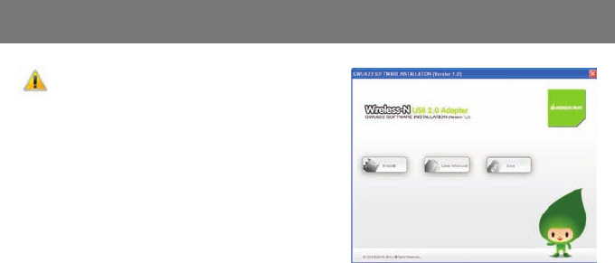
1. Insert the installation CD into your CD-ROM,
it will automatically bring up the auto run
menu. Click Install to begin the software
installation.
8
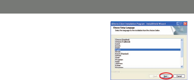
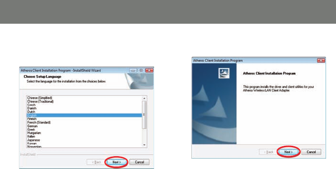
2. Select a language preference and click Next
to continue.
9
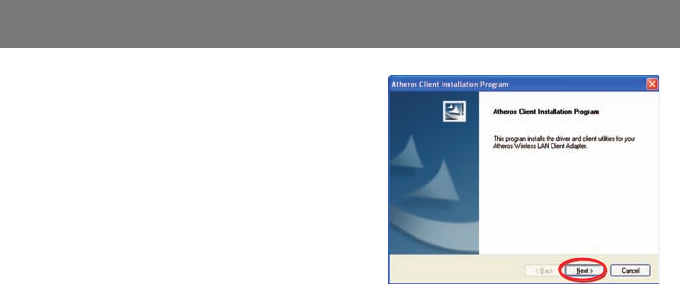
3. Click Next to continue
10
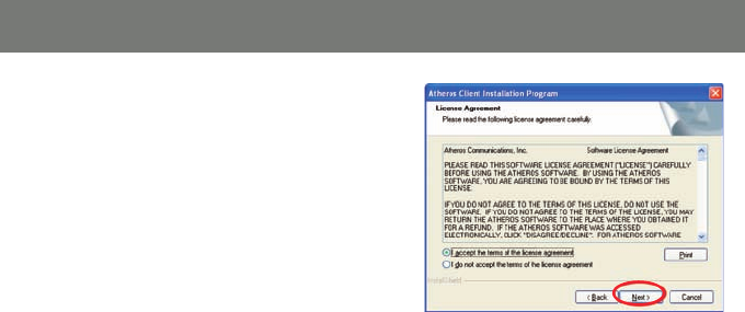
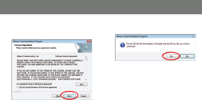
4. This screen shows the software License
Agreement, please choose “I accept the
terms of the license agreement” and click
Next to continue.
11
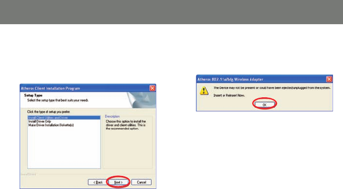
5. It is recommended to choose Install Client
Utilities and Driver so you will be able
to enjoy all features and functions of the
product. Click Next to continue.
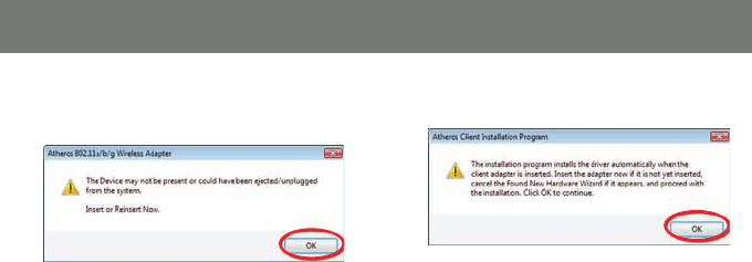
6. Do NOT plug the wireless adapter into the
USB port of your computer, click OK to
continue.
12
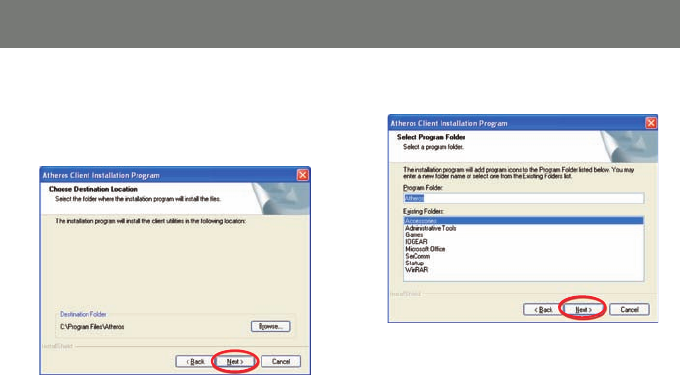
7. Click Next to install the driver in the
designated folder. Or you may choose to
click “Browse” to select a different installation
folder.
8. Click Next to continue.
13
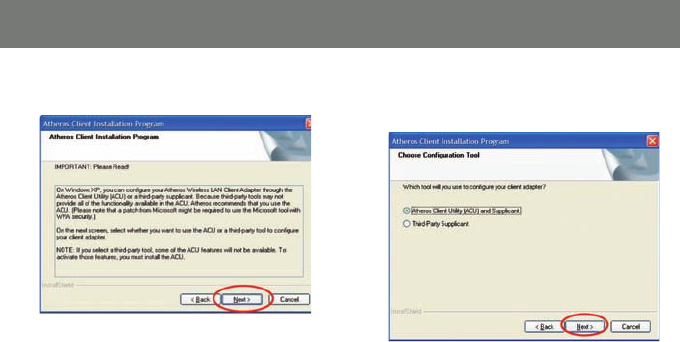
9. Click Next to continue 10. Select Atheros Client Utility (ACU) and
supplicant, and click Next to continue.
14
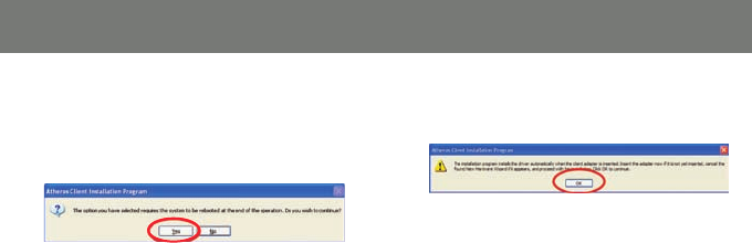
11. The Atheros client will ask you for permis
sion to reboot your computer once the
Atheros software has been installed. Click
Yes to continue.
12. Do NOT insert the adapter now, click OK to
close the window.
15
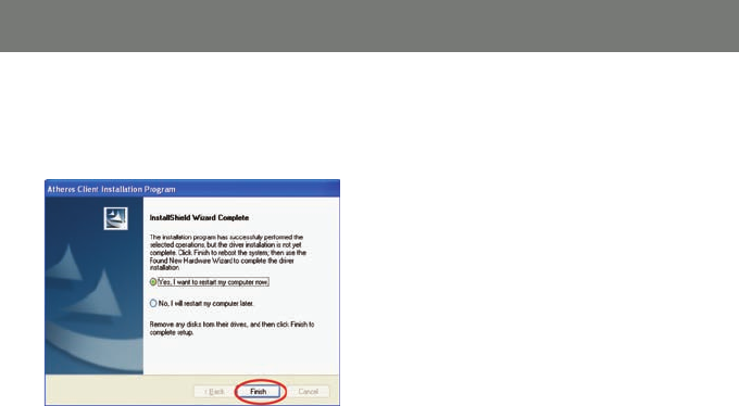
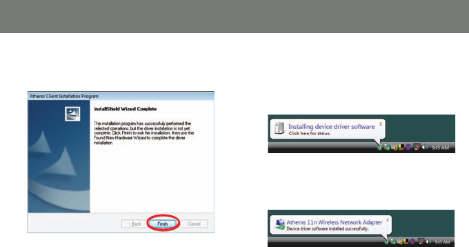
12. You will need to restart your computer
once the installation has been completed.
Click Finish to complete installation and
restart your computer.
13. After the software installation has been
completed and you have restarted your
computer, insert the wireless USB adapter
into your computer.
16
Windows Vista
Before you start the installation, make sure your GWU623 Wireless-N USB 2.0 Adapter is not
plugged into the USB port of your computer. Please plug in the adapter after the software
installation is completed.
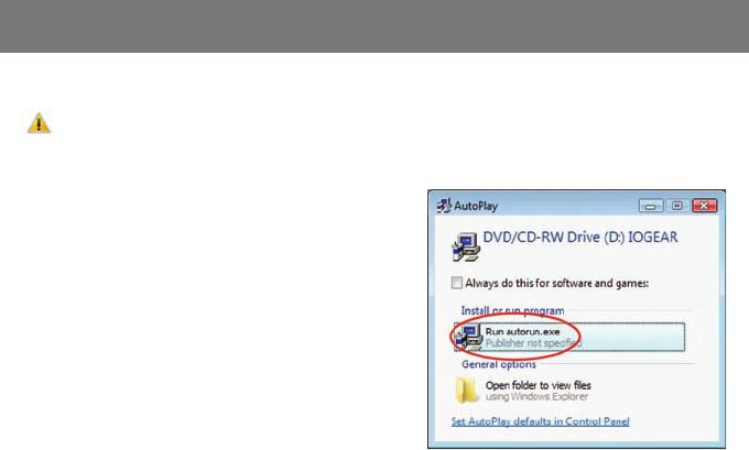
1. Insert the driver CD into the CD-ROM drive.
The AutoPlay window will appear, click Run
autorun.exe
Note: Windows Vista may ask you for permission
to run the installation software. To run the software
you will need to allow permission.
Windows Vista Software Installation

17
2. On the IOGEAR auto-run screen menu, click
on the Install button, then select Windows
Vista to Continue
18
4. Click Next, to continue3. To begin the installation choose a setup
language and click Next.
19
5. Select I accept the terms of the license
agreement and click Next.
6. Click Yes to install the driver
20
7. Do NOT insert the wireless USB adapter,
click OK to continue.
8. Click OK, to continue
21
9. The driver installation has been completed.
Click Finish to close the window.
10.After the software installation is completed,
insert the wireless USB adapter into your
computer. Windows will automatically install
the wireless USB adapter driver
Once driver installation has been completed
you will receive the following message.

22
Windows XP
1. Go to Control Panel (Click on Start > Set-
tings > Control Panel)
2. Click on Add or Remove Programs
3. Click on Atheros Client Installation Program
and click on [Remove]
4. When the un-installation is completed, restart
your computer
Software Un-installation - XP

23
Software Un-installation - Vista
Windows Vista
1. Go to Control Panel (Start > Control Panel)
2. Click on Uninstall a program under Programs
or click on Programs and Features (control
Panel Classic View)
3. Click on the Atheros Client Installation
Program and click on [Uninstall] on the top.
4. When the un-installation is completed,
restart your computer.
24
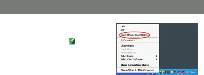
Windows XP
1. After the software installation has been
completed, you will see the Atheros icon on
the task bar. Right click on the icon and
select Open Atheros Client Utility…
Connecting to a Wireless Network - XP
25
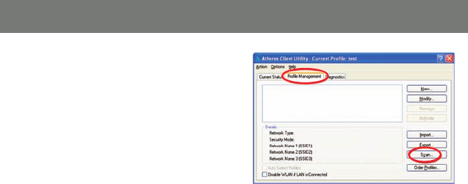
2. Click on Profi le Management tab and click
on the Scan button to search for wireless
netowrks.
26
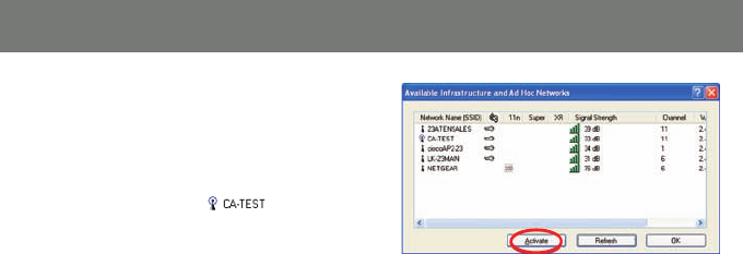
3. The scan will return a list of all available
networks and the details of these networks.
Select the wireless network that you would
like to connect and click Activate. After you
are successfully connected to the network,
you will see the network shows a different
icon as indicated below.
4. You are now connected to the network. Click
OK to close the window
27
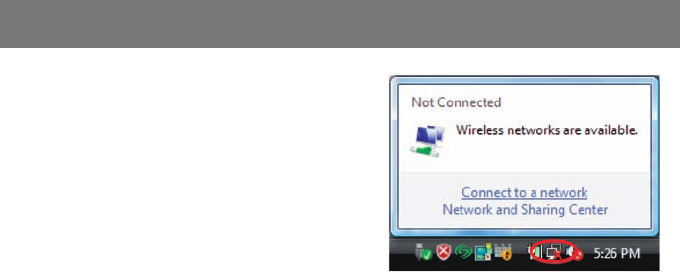
Windows Vista
1. Click the network icon on the task bar and
select Connect to a network.
Connecting to a Wireless Network - Vista
28
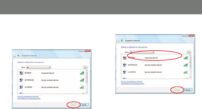
2. The next window will display a list of all
wireless networks around your area. Select
the network that you would like to connect
and click on the Connect button.
3. Select Connect Anyway to continue.
29
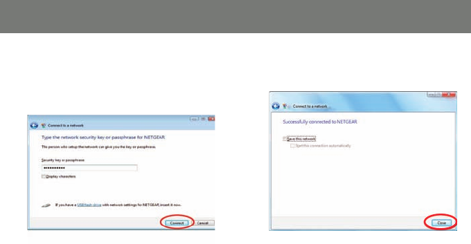
4. If the network you are connecitng has a
netowrk security key or passphrase, enter it
on the fi eld box below and Click Connect to
continue.
5. Click Close once you have successfully
connected to the network.
30
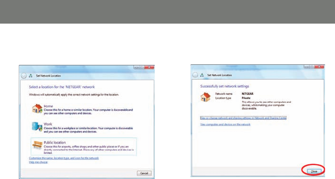
6. Select the connection location that this
network will be used on.
7. Verify the settings and click Close to exit the
window
31
Connecting to a Non-Broadcasting Network
Windows Vista
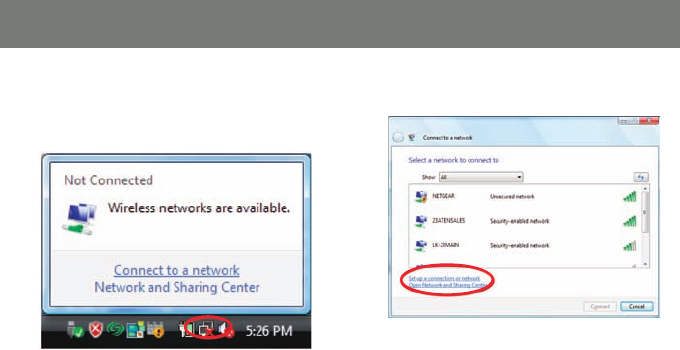
1. Click the network icon on the task bar and
select Connect to a network.
2. Click Set up a connection or network.
32
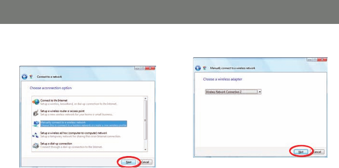
3. Select Manually connect to a wireless
network and click Next.
4. Click Next to continue.
33
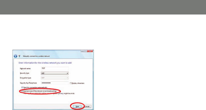
5. Enter the information for the wireless
network you want to add, and check the
box Connect even if the network is not
broadcasting. Click Next to continue
Note: The Network name is the SSID, and it is
broadcasted by your router. You may look up
the SSID information by visiting your router’s
setup page.
34
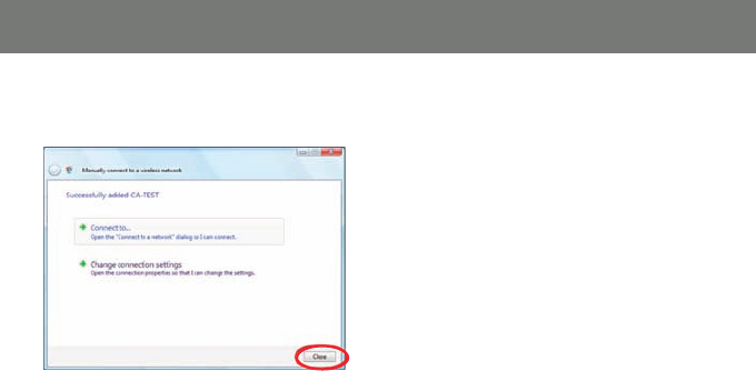
6. Click Close once the network has been
successfully added.
35
Utility Confi guration – Add New Profi le
Windows XP
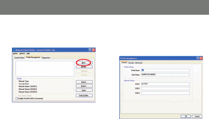
1. To add a new confi guration profi le, click on
New on the Profi le Management tab.
2. Enter the name for the new profi le and
the SSID of the network. The SSID is
broadcasted by your router. You may look
up that information by visiting your router’s
setup page.

36
3. If your network requires you to enter a
security code, please select the appropriate
security option and the passkey phrase.
Click OK to complete the setup.
37
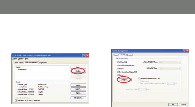
Windows XP
1. To use WEP Passphrase security in the Athe-
ros Client Utility, select the network profi le
that you would like to confi gure and click on
Modify on the right.
2. Select the Security tab in the Profi le
Management window, and choose the
Pre-Shared Key (Static WEP) radio button
then click on Confi gure to continue.
Utility Confi guration - Using WEP Encryption
38
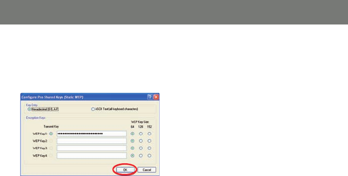
3. Fill in the WEP Passphrase, click OK when
fi nished. You may choose the WEP Key Size
as you wish, and the length of your WEP key
will depends on the WEP Key Size that you
select.
39
Utility Confi guration - Using WPA Security
Windows XP
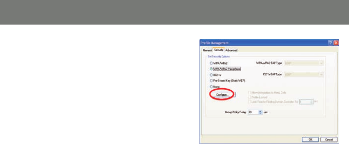
1. To use WPA Passphrase security in the Athe-
ros Client Utility, select the network profi le
that you would like to confi gure and click on
Modify on the right. Select the Security tab
in the Profi le Management window. On the
Security tab, choose the WPA/WPA2 Pass-
phrase radio button, then click on Confi gure
to continue.
40
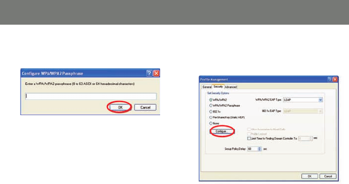
2. Fill in the Passphrase of your choice then
click OK when fi nished
3. To use the WPA/WPA2 security, click on
the WPA/WPA2 radio button, then click on
Confi gure to continue.
41
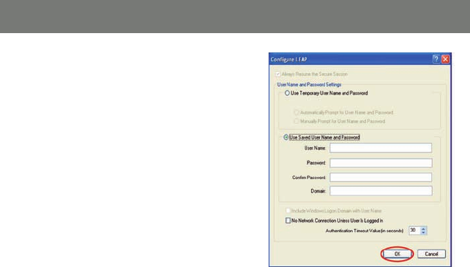
4. Input the information of your choice then
click OK to fi nish.
42
Windows XP
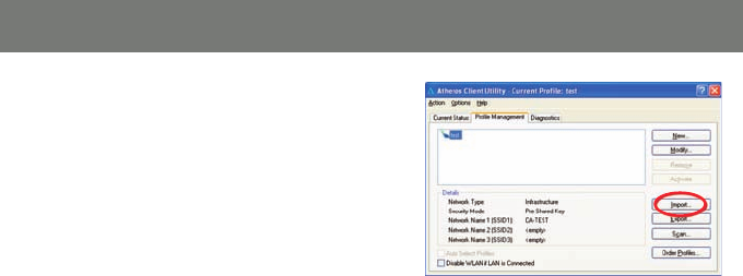
1. If you would like to import a profi le that has
already been created, click on Import.
Browse to the directory where the profi le is
located.
Utility Confi guration - Import and Export Profi les
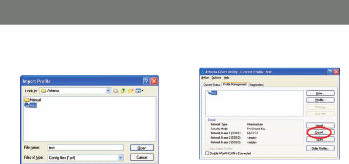
43
2. Browse to the directory where the profi le
is located. Highlight the profi le name then
Click Open.
3. If you would like to export a profi le, highlight
the profi le then click on Export to continue.
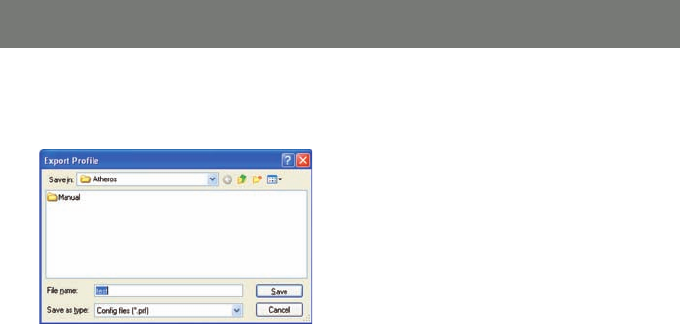
44
4. Browse to the directory to export the profi le
to then Click Save to confi rm. The profi le is
now exported to the specifi ed location
45
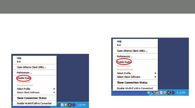
Windows XP
1. If you would like to disable a Wi-Fi
connection temporary, you may do so by
right clicking on the Atheros icon in the
system tray and selecting Disable Radio.
2. You may re-establish the Wi-Fi connection at
anytime by selecting Enable Radio
Utility Confi guration - Disable / Enable Wi-Fi
46
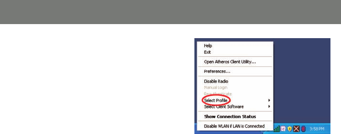
Windows XP
To switch to a different network you will need to
right click on the Atheros icon and select profi le.
Make sure that you select the network that you
would like to connect.
Please see page 10 to setup a new network
profi le.
Utility Confi guration - Profi le Selection
47
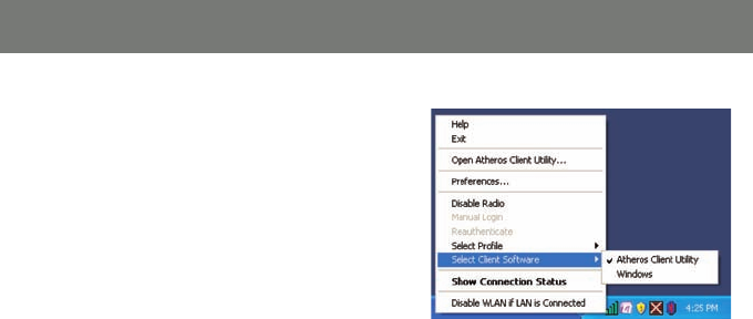
Windows XP
If you would like to use the Windows wireless
client instead of the Atheros software, you may
do so by selecting, Select Client software from
the Atheros menu.
Utility Confi guration - Wireless Client Selection.

48
The Jumpstart application will allow you to setup Wi-Fi Protected setup (WPS) on your wireless network.
Using WPS will automatically confi gure a wireless network SSID, and setup WPA encryption and
authentication for your network. Please remember that your router must also support WPS.
On the IOGEAR installation CD, open the “JSW_Install_CD” folder, and double click on the setup.exe icon.
Follow the installation wizard, once completed you will fi nd the Jumpstart icon on your desktop.
WPS Installation
49
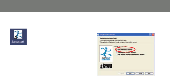
1. Double click on the Jumpstart icon 2. Select Join a wireless network and click
Next
Note: There are two ways to setup WPS. One
is by pushing the integrated WPS button on
your router and the other is by entering the
access PIN from your USB adapter to establish
the WPS encryption with your router.
WPS Confi guration – Push Button
50
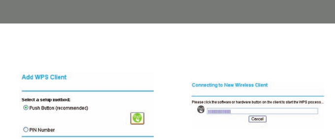
3. If your router has an integrated WPS button,
then select the Push Button selection to
continue.
4. Your router will prompt you to click the
integrated WPS button on your USB adapter
or the WPS button on your access point
(Router) setup interface.
51
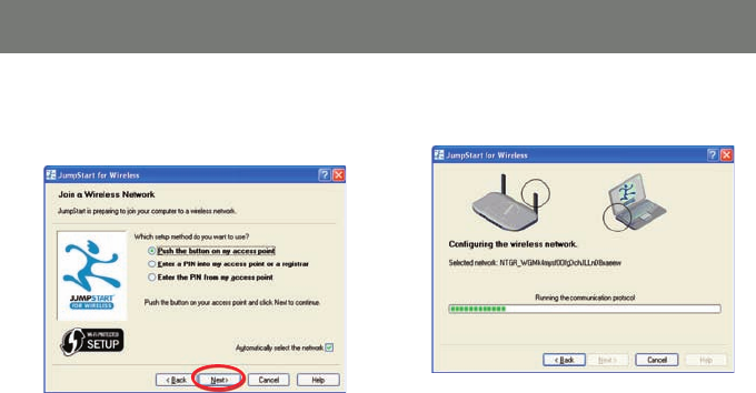
5. Following the Jumpstart application, and
select Push the button on my access
point, click Next to continue.
6. The wizard will confi gure the wireless
network.
52
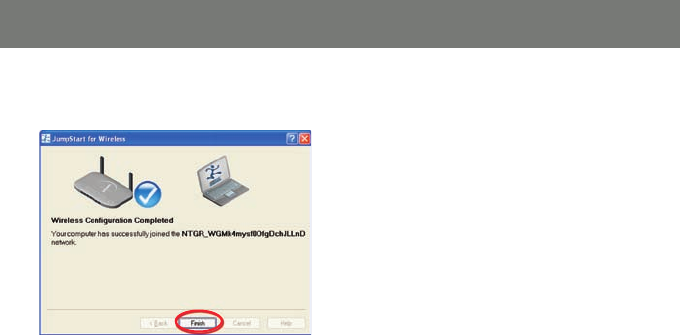
7. Once completed, click fi nish to close the
window.
53
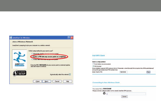
1. To setup WPS by entering PIN, you will need
to select Enter a PIN into my access
point or a registrar.
2. Locate the WPS confi guration setup on your
WPS enabled access point (Router) and
select PIN number as the setup method.
3. Enter the PIN number that is given on the
Jumpstart Window into your WPS enabled
access point (Router) and click Next to
continue.
WPS Confi guration - PIN Access
54
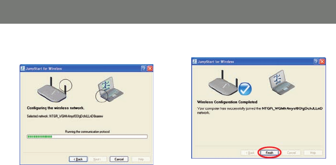
4. The wizard will confi gure the wireless
network
5. Click Finish to complete the setup.
55
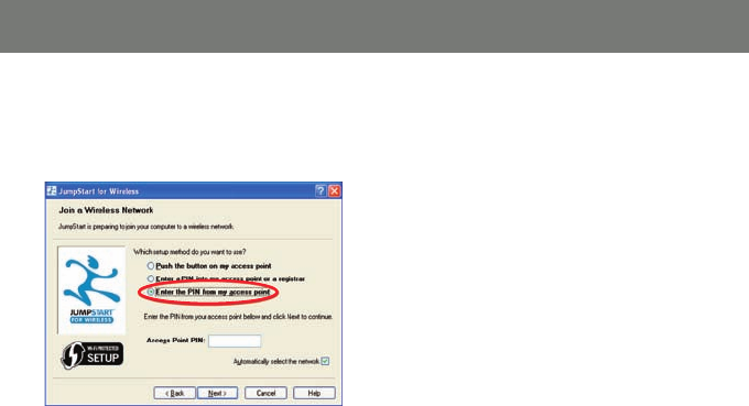
WPS Confi guration – PIN Access Part II
1. If you would like to setup WPS by entering
the PIN from your WPS enabled access
point (Router), select Enter the PIN from
my access point.
2. Your WPS enabled access point (Router) will
come with a specifi c PIN that will to be used
with the Jumstart application. Please check
with your access point (Router) user manual
if you can not locate the access point
(Router) PIN.
56
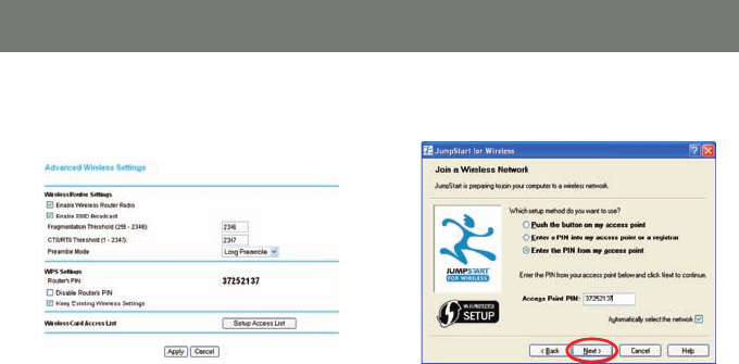
3. Enter the PIN on the Jumpstart setup wizard
and click Next to continue.
Example: Below is the screen shot on
setting up the WPS on Netgear WNR843B
router.
57
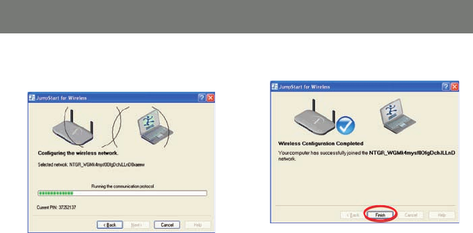
4. The wizard will confi gure the wireless
network.
5. Click Finish to complete the setup.

58
Specifi cations
Model GWU623
Standard 802.11b/g/n
Data Transfer Rate 1,2,5.5,6,11,12,18,22,24,30,36,48,54,60,90,120,180,240,270 and maximum of 300Mbps
Modulation Method BPSK/QPSK/16-QAM/64-QAM
Frequency Band 2.4GHz ISM Band
Spread Spectrum IEEE 802.11b: DSSS (Direct Sequence Spread Spectrum) IEEE 802.11g /n: OFDM
(Orthogonal Frequency Division Multiplexing)
RF Output Power < 13.5dBm@11n, <13.5dBm@11b, <13.5dBm@11g
Operation Range Indoor@Up to 100 meters, Outdoor@Up to 280 meters
LED Power
OS Support Win 2000 / XP / Vista
Security 64 bit/128 bit WEP, TKIP, AES
Power Consumption Transmit: around 380 mA
Receive: around 250 mA
Operating Temperature 0 - 50° C ambient temperature
Humidity 5 to 90% maximum (non-condensing)
Dimension 3.5x1x0.37 inches

59
Glossary
IEEE 802.11 Standard
The IEEE 802.11 Wireless LAN standards subcommittee, which is formulating a standard for the industry.
Access Point
An internetworking device that seamlessly connects wired and wireless networks together.
Ad Hoc
An Ad Hoc wireless LAN is a group of computers, each with a WLAN adapter, connected as an
independent wireless LAN. Ad Hoc wireless LAN is applicable at a departmental scale for a branch or
SOHO operation.
BSSID
A specifi c Ad Hoc LAN is called a Basic Service Set (BSS). Computers in a
BSS must be confi gured with the same BSSID.

60
DHCP
Dynamic Host Confi guration Protocol - a method in which IP addresses are assigned by server
dynamically to clients on the network. DHCP is used for Dynamic IP Addressing and requires a dedicated
DHCP server on the network.
Direct Sequence Spread Spectrum
This is the method the wireless cards use to transmit data over the frequency spectrum. The other
method is frequency hopping. Direct sequence spreads the data over one frequency range (channel) while
frequency hopping jumps from one narrow frequency band to another many times per second.
ESSID
An Infrastructure confi guration could also support roaming capability for mobile workers. More than one
BSS can be confi gured as an Extended Service Set (ESS). Users within an ESS could roam freely between
BSSs while served as a continuous connection to the network wireless stations and Access Points within
an ESS must be confi gured with the same ESSID and the same radio channel.

61
Ethernet
Ethernet is a 10/100Mbps network that runs over dedicated home/offi ce wiring. Users must be wired to
the network at all times to gain access.
Gateway
A gateway is a hardware and software device that connects two dissimilar systems, such as a LAN and a
mainframe. In Internet terminology, a gateway is another name for a router. Generally a gateway is used as
a funnel for all traffi c to the Internet.
IEEE
Institute of Electrical and Electronics Engineers
Infrastructure
An integrated wireless and wired LAN is called an Infrastructure confi guration. Infrastructure is applicable
to enterprise scale for wireless access to central database, or wireless application for mobile workers.

62
ISM Band
The FCC and their counterparts outside of the U.S. have set aside bandwidth for unlicensed use in the
so-called ISM (Industrial, Scientifi c and Medical) band. Spectrum in the vicinity of 2.4 GHz, in particular, is
being made available worldwide. This presents a truly revolutionary opportunity to place convenient high-
speed wireless capabilities in the hands of users around the globe.
Local Area Network (LAN)
A LAN is a group of computers, each equipped with the appropriate network adapter card connected by
cable/air, that share applications, data, and peripherals. All connections are made via cable or wireless
media, but a LAN does not use telephone services. It typically spans a single building or campus.
Network
A network is a system of computers that is connected. Data, fi les, and messages can be transmitted over
this network. Networks may be local or wide area networks.

63
Protocol
A protocol is a standardized set of rules that specify how a conversation is to take place, including the
format, timing, sequencing and/ or error checking.
Roaming
In an infrastructure network, this is when a wireless PC moves out of range of the previously connected
access point and connects to a newly connected access point. Throughout the network environment
where access point is deployed, PCs can always be connected regardless of where they are located or
roam.
SSID
A Network ID unique to a network. Only clients and Access Points that share the same SSID are able to
communicate with each other. This string is case-sensitive.

64
Simple Network Management Protocol (SNMP)
Simple Network Management Protocol is the network management protocol of TCP/IP. In SNMP,
agents-which can be hardware as well as software - monitor the activity in the various devices on
the network and report to the network console workstation. Control information about each device is
maintained in a structure known as a management information block.
Static IP Addressing
A method of assigning IP addresses to clients on the network. In networks with Static IP address, the
network administrator manually assigns an IP address to each computer. Once a Static IP address
is assigned, a computer uses the same IP address every time it reboots and logs on to the network,
unless it is manually changed.
Temporal Key Integrity Protocol (TKIP)
The Temporal Key Integrity Protocol, pronounced tee-kip, is part of the IEEE 802.11i encryption
standard for wireless LANs. TKIP is the next generation of WEP, the Wired Equivalency Protocol, which
is used to secure 802.11 wireless LANs. TKIP provides per-packet key mixing, a message integrity
check and a re-keying mechanism, thus fi xing the fl aws of WEP.

65
Transmission Control Protocol / Internet Protocol (TCP/IP)
TCP/IP is the protocol suite developed by the Advanced Research Projects Agency (ARPA). It is widely
used in corporate Internet works, because of its superior design for WANs. TCP governs how packet is
sequenced for transmission the network. The term “TCP/IP” is often used generically to refer to the entire
suite of related protocols.
Transmit / Receive
The wireless throughput in Bytes per second averaged over two seconds.
Wi-Fi Alliance
The Wi-Fi Alliance is a nonprofi t international association formed in 1999 to certify interoperability of
wireless Local Area Network products based on IEEE 802.11 specifi cation. The goal of the Wi-Fi Alliance’s
members is to enhance the user experience through product interoperability. The organization is formerly
known as WECA.

66
Wi-Fi Protected Access (WPA)
The Wi-Fi Alliance put together WPA as a data encryption method for 802.11 wireless LANs. WPA is an
industry-supported, pre-standard version of 802.11i utilizing the Temporal Key Integrity Protocol (TKIP),
which fi xes the problems of WEP, including using dynamic keys.
Wide Area Network (WAN)
A WAN consists of multiple LANs that are tied together via telephone services and / or fi ber optic cabling.
WANs may span a city, a state, a country, or even the world.
Wired Equivalent Privacy (WEP)
Now widely recognized as fl awed, WEP was a data encryption method used to protect the transmission
between 802.11 wireless clients and APs. However, it used the same key among all communicating
devices. WEP’s problems are well-known, including an insuffi cient key length and no automated method
for distributing the keys. WEP can be easily cracked in a couple of hours with off-the-shelf tools.

67
Wireless LAN (WLAN)
A wireless LAN does not use cable to transmit signals, but rather uses radio or infrared to transmit packets
through the air. Radio Frequency (RF) and infrared are the commonly used types of wireless transmission.
Most wireless LANs use spread spectrum technology. It offers limited bandwidth, usually under 11Mbps,
and users share the bandwidth with other devices in the spectrum; however, users can operate a spread
spectrum device without licensing from the Federal Communications Commission (FCC).

68
If you need technical support, please check out our IOGEAR Tech Info Library (T.I.L.) at www.iogear. com/
support for the latest tips, tricks, and troubleshooting. The IOGEAR T.I.L. was designed to provide you
with the latest technical information about our products. Most of the answers to your questions can be
found here, so please try it out before contacting technical support. Technical support is available Monday
through Friday from 8:00 am to 5:00 pm PST and can be reached at (949) 453-8782 and (866) 946-4327
or by email support@iogear.com.
Technical support

69
Federal Communications Commission (FCC) Statement
15.21
You are cautioned that changes or modifi cations not expressly approved by the part responsible for com-
pliance could void the user’s authority to operate the equipment.
15.105(b)
This equipment has been tested and found to comply with the limits for a Class B digital device, pursuant
to part 15 of the FCC rules. These limits are designed to provide reasonable protection against harmful
interference in a residential installation. This equipment generates, uses and can radiate radio frequency
energy and, if not installed and used in accordance with the instructions, may cause harmful interference
to radio communications. However, there is no guarantee that interference will not occur in a particular
installation. If this equipment does cause harmful interference to radio or television reception, which can be
determined by turning the equipment off and on, the user is encouraged to try to correct the interference
by one or more of the following measures:
Reorient or relocate the receiving antenna.•
Increase the separation between the equipment and receiver.•
Connect the equipment into an outlet on a circuit different from that to which the receiver is connected.•
Consult the dealer or an experienced radio/TV technician for help.•

70
Operation is subject to the following two conditions:
this device may not cause interference and1.
this device must accept any interference, including interference that may cause undesired operation of 2.
the device.
FCC RF Radiation Exposure Statement:
This equipment complies with FCC radiation exposure limits set forth for an uncontrolled environment. End
users must follow the specifi c operating instructions for satisfying RF exposure compliance. This transmitter
must not be co-located or operating in conjunction with any other antenna or transmitter.

71
This device has been tested and found to comply with the requirements set up in the council directive on
the approximation of the law of member states relating to EMC Directive 89/336/EEC, Low Voltage Directive
73/23/EEC and R&TTE Directive 99/5/EC.
CE Statement

72
Limited Warranty
IN NO EVENT SHALL THE DIRECT VENDOR’S LIABILITY FOR DIRECT, INDIRECT, SPECIAL,
INCIDENTAL OR CONSEQUENTIAL DAMAGES RESULTING FROM THE USE OF THE PRODUCT,
DISK OR ITS DOCUMENTATION EXCEED THE PRICE PAID FOR THE PRODUCT.
The direct vendor makes no warranty or representation, expressed, implied, or statutory with respect to
the contents or use of this documentation, and especially disclaims its quality, performance,
merchantability, or fi tness for any particular purpose.
The direct vendor also reserves the right to revise or update the device or documentation without
obligation to notify any individual or entity of such revisions, or updates. For further inquires please
contact your direct vendor.

73
Contact
IOGEAR, INC.
23 Hubble
Irvine, CA 92618
P 949.453.8782
F 949.453.8785
Visit us at: www.iogear.com
©2008 IOGEAR. All Rights Reserved. PKG-M1209
IOGEAR and the IOGEAR logo are trademarks or registered trademarks of IOGEAR, Inc. Microsoft and Windows are
registered trademarks of Microsoft Corporation. IBM is a registered trademark of International Business Machines, Inc.
IOGEAR makes no warranty of any kind with regards to the information presented in this document. All information
furnished here is for informational purposes only and is subject to change without notice. IOGEAR, Inc. assumes no
responsibility for any inaccuracies or errors that may appear in this

74

75

© 2007 IOGEAR, INC.
FUN
IOGEAR offers connectivity solutions that are innovative, fun, and stylish,
helping people enjoy daily life using our high technology products.
GREEN
IOGEAR is an environmentally conscious company that emphasizes the
importance of conserving natural resources. The use of our technology
solutions helps reduce electronic waste.
HEALTH
IOGEAR supports healthy and fi t lifestyles. By integrating products with
the latest scientifi c developments, IOGEAR’s solutions enhance the life of
end-users.
About Us
About Us
About Us