ATEQ INSTRUMENTS TPMS4 Tire-pressure monitoring system (TPMS) User Manual Layout 1
ATEQ INSTRUMENTS (ASIA) PTE LTD.TAIWAN BRANCH (SINGAPORE) Tire-pressure monitoring system (TPMS) Layout 1
UserManual.wiki
>
ATEQ INSTRUMENTS
>
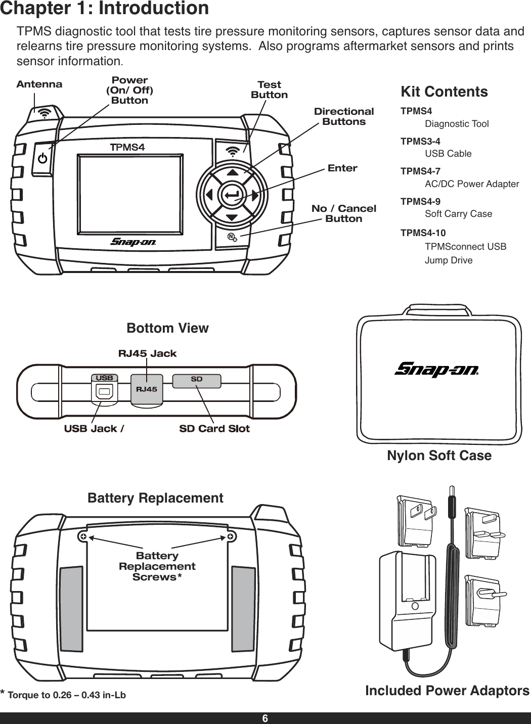
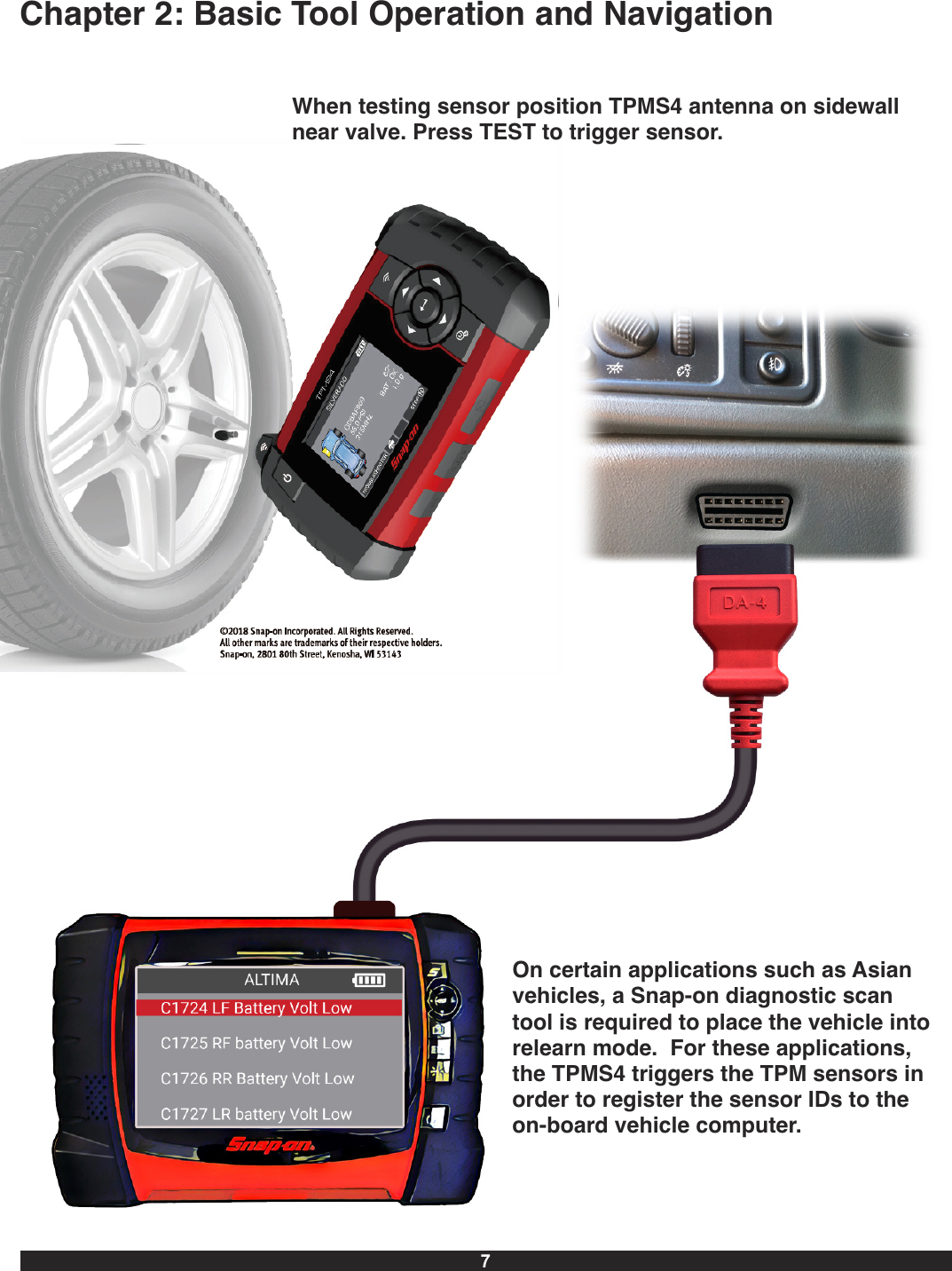
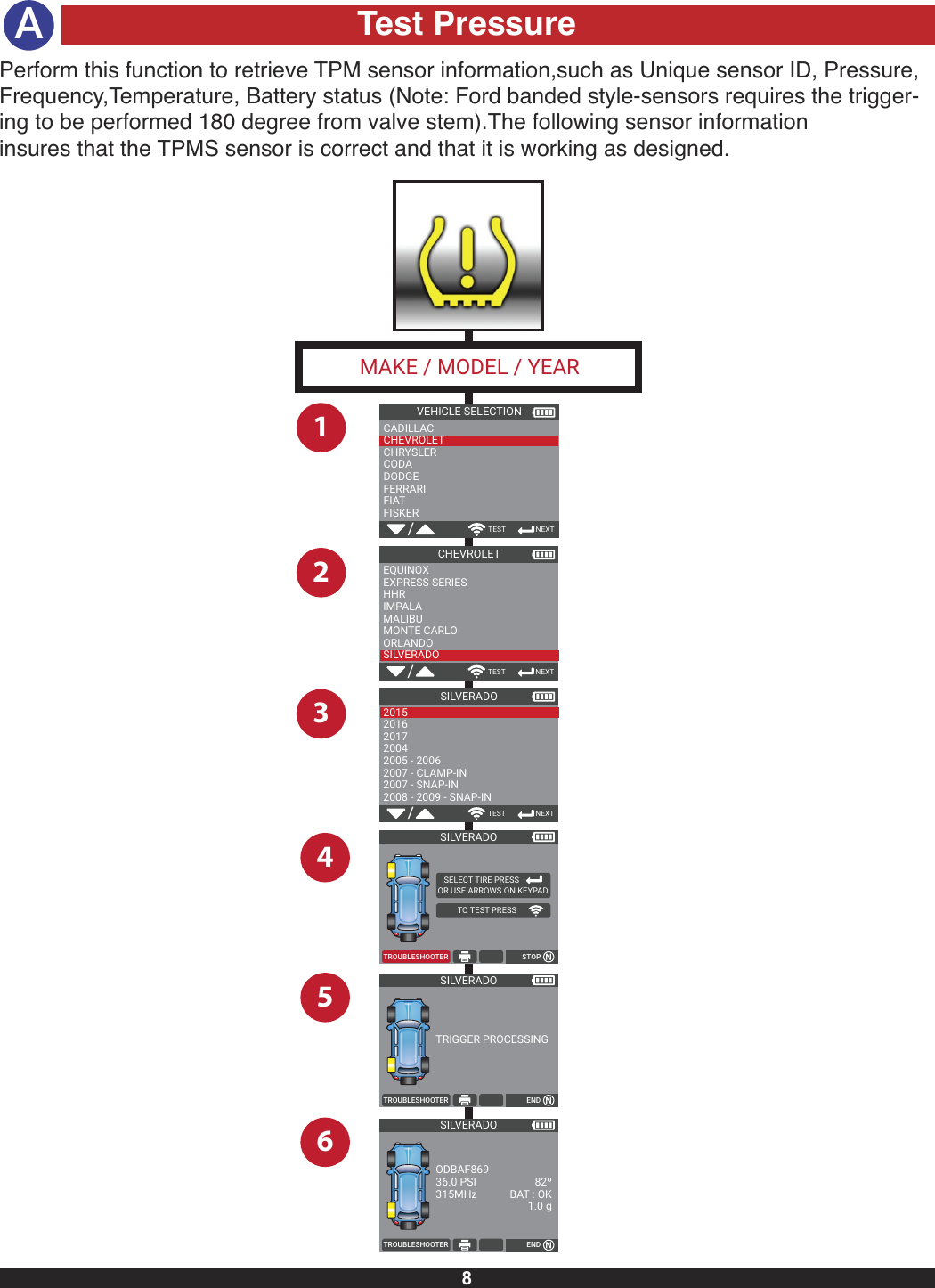
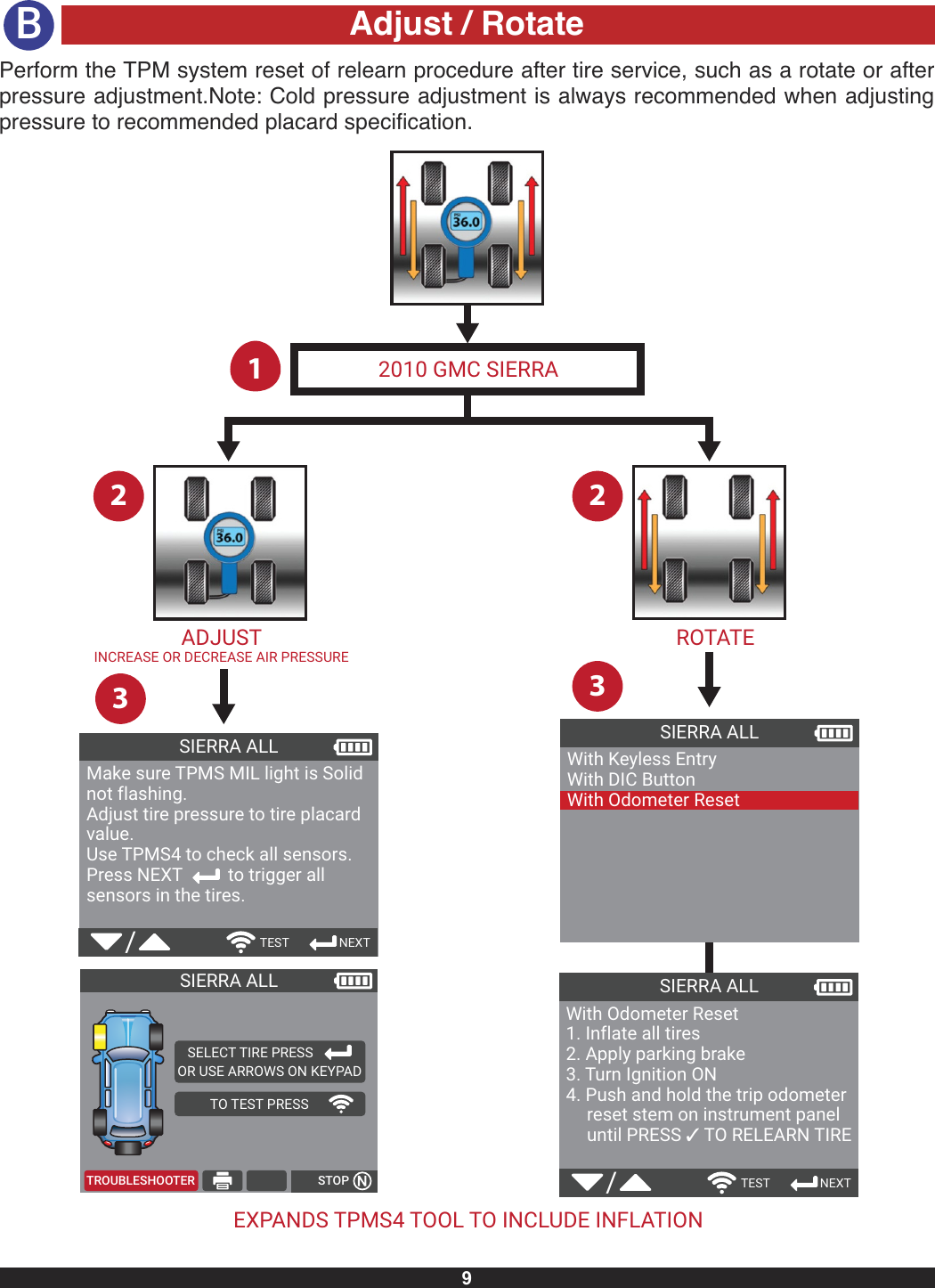
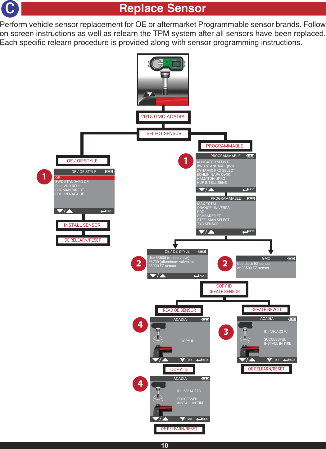
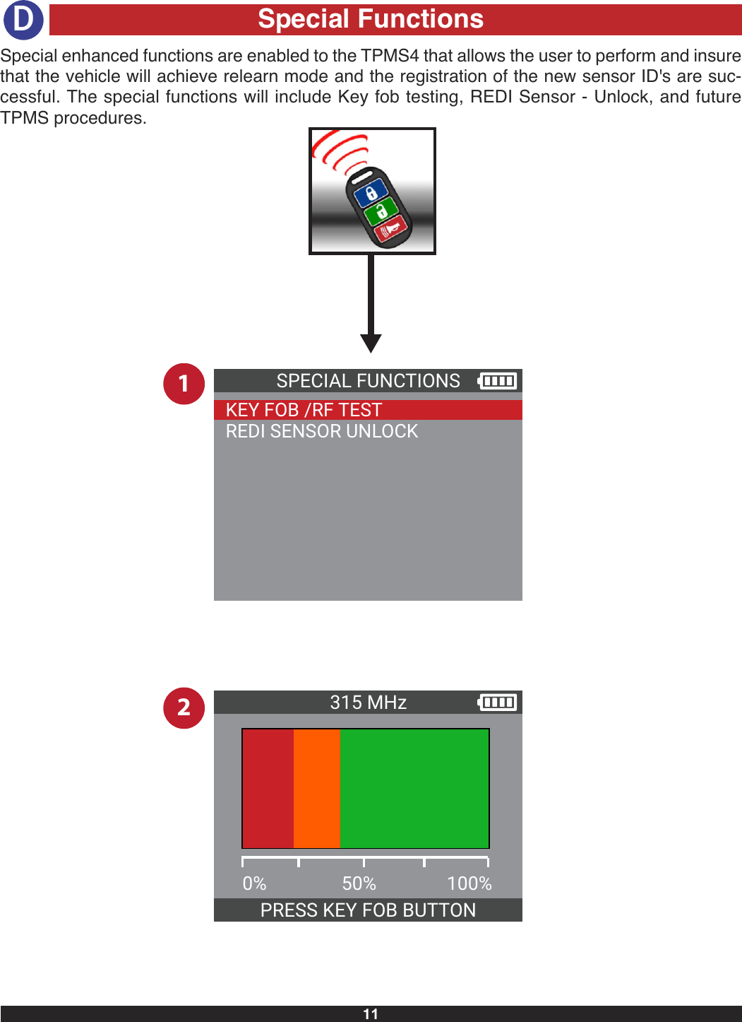
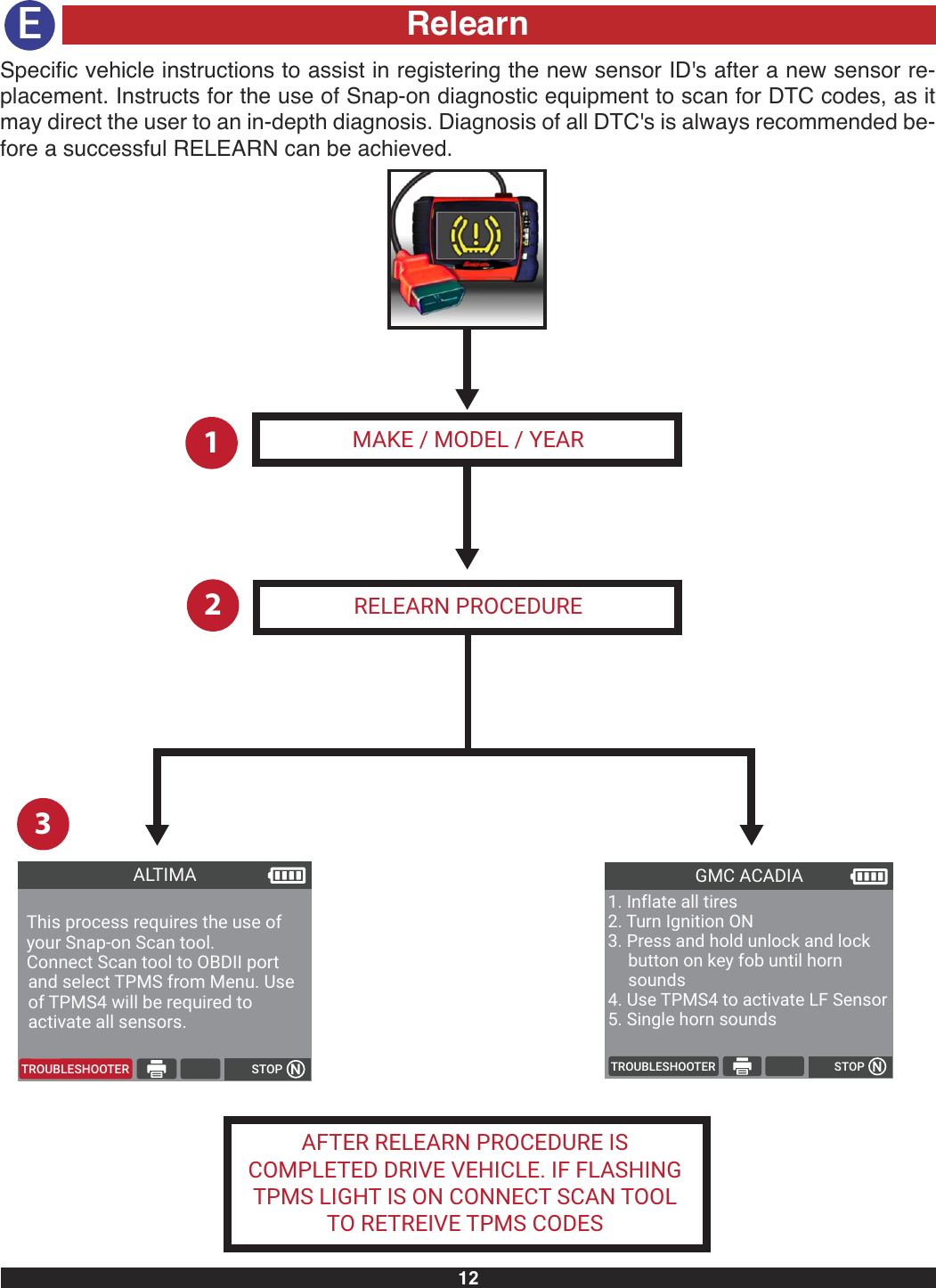
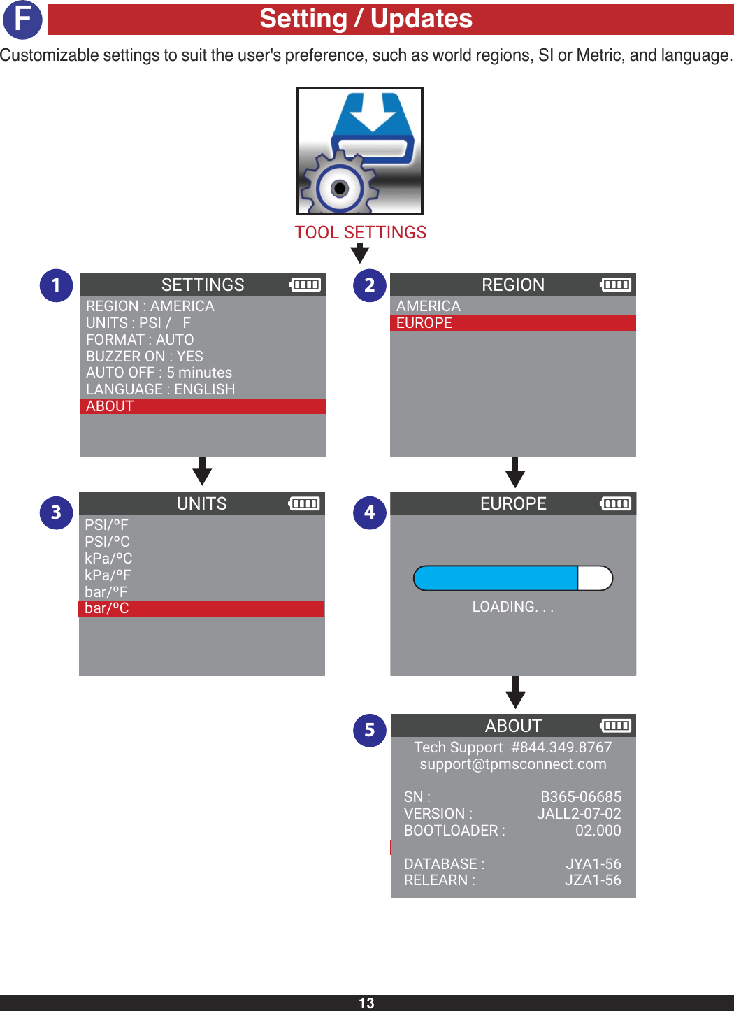
TPMS4 User Manual
Users Manual
Navigation menu
Upload a User Manual
Namespaces
Wiki Guide
HTML
PDF
Info
Views
User Manual
Discussion / Help
Navigation