ATEQ VT15 Tire-Pressure monitoring system (TPMS) User Manual
A.T.E.Q.(THAILAND) Co., Ltd. Tire-Pressure monitoring system (TPMS) Users Manual
ATEQ >
Users Manual
USER MANUAL
VT15_2B
TPMS trigger tool
Forceur de Valve
Ventil-Auslöser
Forzatore delle valvole
Ventiltvingare
Venttiilinohjain
Forzador de válvulas
Ventiltester
Signaalforcering van ventielen
Aparelho de teste válvulas
TABLE OF CONTENTS
USER GUIDE VT15
1. DESCRIPTION OF THE ATEQ VT15_2 BUTTONS
1.1. Front face
2. LIGHT INDICATORS
3.KEYS
3.1. Power on key
3.2. Cycle key
4. TRIGGER SELECTION
5. SETTING ADJUSTMENT FOR VT 15_2 BUTTONS
6 TRIGGER THE SENSOR
7.RADIO FREQUENCIES
8. Appendices ATEQ VTXX
8.1. Recycling the battery
8.2. Recycling the product
8.3 Security

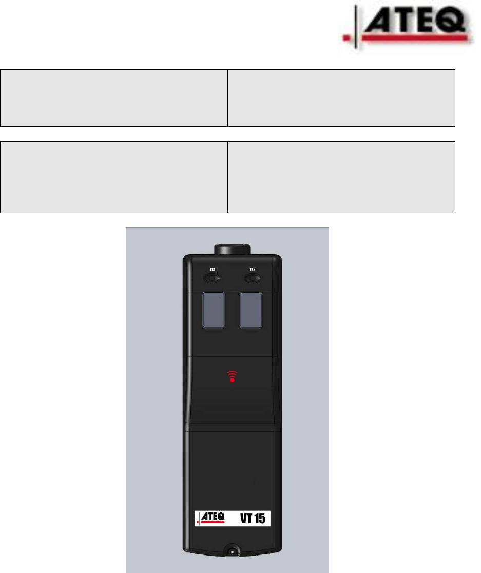
1. DESCRIPTION OF VT15_2 BUTTONS
FRONT FACE
DESCRIPTION
The principle of this instrument is to awaken smart sensors mounted on
vehicle wheels.
The instrument interacts with the smart sensors without contact.
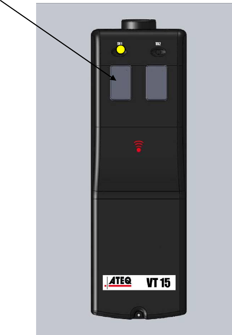
2. LIGHT INDICATOR
TRANSMISSION LIGHT: When this light is ON the tool is currently
transmitting a signal to activate a sensor.
LO BAT: when this is on, the battery level becoming too low for reliable
operation, indicating that the battery must be replaced before further use.
LF ANTENNAE
LED LO BAT
TRANSMISSION
LIGHT
POWER OFF KEY
POWER ON KEY
3.KEYS
“Power on” key and “Power off” key
Push and release the left keys.
The VT15 starts to send the sequence of the trigger signal to the sensor.
Push and release again the left keys, the VT 15 restarts the sequence at the
origin.
Push on the right key and the VT15 POWER OFF.
RMQ : The VT15 power off automatically at the end of the sequence.
4.TRIGGER SELECTION
The VT15 is universal and send the entire LF trigger sequentially.
SCHRADER / CONTINENTAL / BERU / TRW / PACIFIC / LEAR /
CONTINENTAL
5. SETTING ADJUSTMENT FOR VT15_2 buttons
The VT10 is automatic and all the parameters are already adjusted.
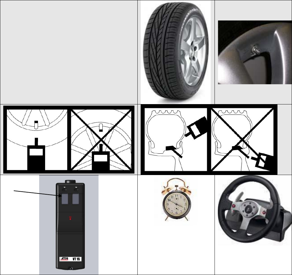
6 TRIGGER THE SENSOR
The VT15 must be close to the sensor. See the picture for the right
position. The left key must be pressed and released until the sensor
answers. The answering time could be 1 to 50 sec.
TEST
1 to 50 Sec
OK
7 RADIO FREQUENCIES
The awakening transmission frequency is: 125 kHz (LF).
8. Appendices any ATEQ VTXX
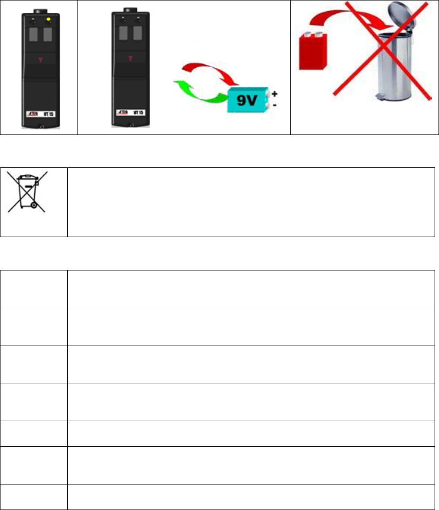
8.1. Recycling the battery
8.2. Recycling the product
The crossed-out wheeled dustbin means that within the EU the product must
be taken to separate collection at the product end-of life. This applies to
your tool but also to any enhancements marked with this symbol. Do not
dispose of these products as unsorted municipal waste. For further
information, please contact ATEQ.
8.3 Security
SWITCH ON SAFELY
Do not switch on the device when wireless tool is prohibited or when it
may cause interference or danger.
SWITCH OFF WHEN REFUELLING
Do not use the device at a refuelling point. Do not use near fuel or
chemicals.
SWITCH OFF NEAR BLASTING
Follow any restrictions. Do not use the device where blasting is in
progress.
USE SENSIBLY
Use only in the normal position as explained in the product documentation.
Do not touch the antenna unnecessarily.
QUALIFIED SERVICE
Only qualified personnel may install or repair this device.
EHANCEMENTS AND BATTERIES
Use only approved enhancements and batteries. Do not connect
incompatible products.
WATER-RESISTANCE
The device is not water-resistant. Keep it dry.
Federal Communication Commission Interference Statement
This equipment has been tested and found to comply with the limits for a Class B digital
device, pursuant to Part 15 of the FCC Rules. These limits are designed to provide reasonable
protection against harmful interference in a residential installation. This equipment generates, uses
and can radiate radio frequency energy and, if not installed and used in accordance with the
instructions, may cause harmful interference to radio communications. However, there is no
guarantee that interference will not occur in a particular installation. If this equipment does cause
harmful interference to radio or television reception, which can be determined by turning the
equipment off and on, the user is encouraged to try to correct the interference by one of the
following measures:
- Reorient or relocate the receiving antenna.
- Increase the separation between the equipment and receiver.
- Connect the equipment into an outlet on a circuit different from that
to which the receiver is connected.
- Consult the dealer or an experienced radio/TV technician for help.
FCC Caution: Any changes or modifications not expressly approved by the party responsible
for compliance could void the user's authority to operate this equipment.
This device complies with Part 15 of the FCC Rules. Operation is subject to the following two
conditions: (1) This device may not cause harmful interference, and (2) this device must accept any
interference received, including interference that may cause undesired operation.