User Manual

June 2012
AT-R2000-S1
USER’S MANUAL
V2.06.29
AT-R2000-S1 User’s Manual
Company Date Version
ATID Co.,Ltd 2012-06-29 V2.06.29
2
Identification with Radio and Optical
Revision history
Version Revision Date Revision Page Revision Description
V2.6.29 2012-06-29 Draft

AT-R2000-S1 User’s Manual
Company Date Version
ATID Co.,Ltd 2012-06-29 V2.06.29
3
Identification with Radio and Optical
Contents
1. Introduction & System composition diagram .......................................................... 4
Introduction ................................................................................................................................................. 4
System composition diagram ............................................................................................................ 4
2. Composition parts .......................................................................................................... 5
3. Reader Description ......................................................................................................... 6
4. Reader Specification ....................................................................................................... 8
Reader Performance (KOREA, USA, EUROPE, etc) .................................................................. 8
Interface ......................................................................................................................................................... 8
Physical Dimension .................................................................................................................................. 8
Channel number & Frequency table .............................................................................................. 9
Mechanical Dimension ........................................................................................................................ 10
5. How to Run AT-R2000-S1 Sample Program .......................................................... 11
Appendix I : FCC Certification Requirements ......................................................... 13
AT-R2000-S1 User’s Manual
Company Date Version
ATID Co.,Ltd 2012-06-29 V2.06.29
4
Identification with Radio and Optical
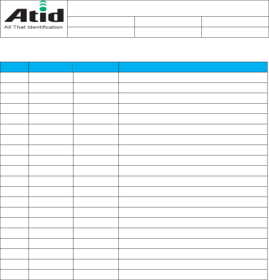
1. Introduction & System composition diagram
Introduction
- The AT-R2000-S1 is a compact size RFID reader module developed for
the embedded reader market, which comprises printers, industrial PDA,
and similar devices. It provides customers with compact size, low cost,
high performance functions. It supports protocols of ISO18000-6C(EPC
C1G2), and it interfaces with a host system via UART.
- Target Application
PDA type RFID Reader
RFID Printers / Tag Encoders
USB Readers
Smart-Shelves
System composition diagram
AT-R2000-S1 User’s Manual
Company Date Version
ATID Co.,Ltd 2012-06-29 V2.06.29
5
Identification with Radio and Optical
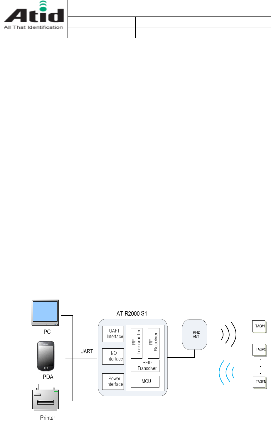
2. Composition parts
RFID Reader module
Interface Cable
ANTENNA
(option)
UART to USB Convertor
(option)
AT-R2000-S1 User’s Manual
Company Date Version
ATID Co.,Ltd 2012-06-29 V2.06.29
6
Identification with Radio and Optical
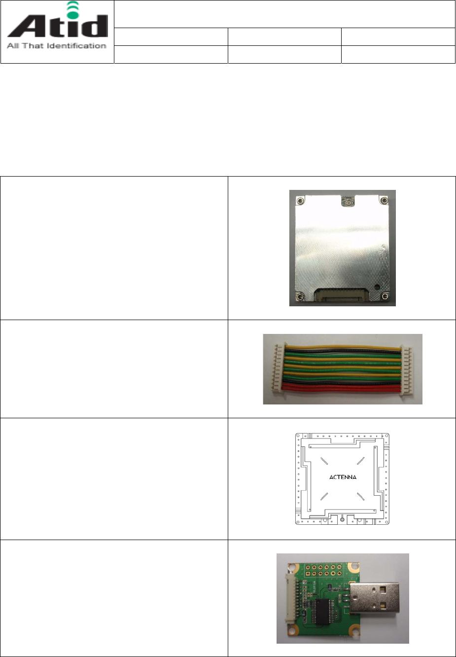
Reader Software &
User Document CD-ROM
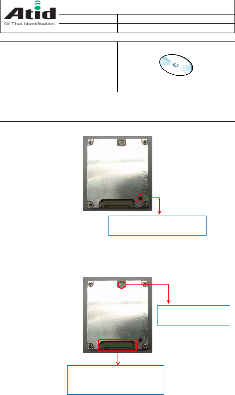
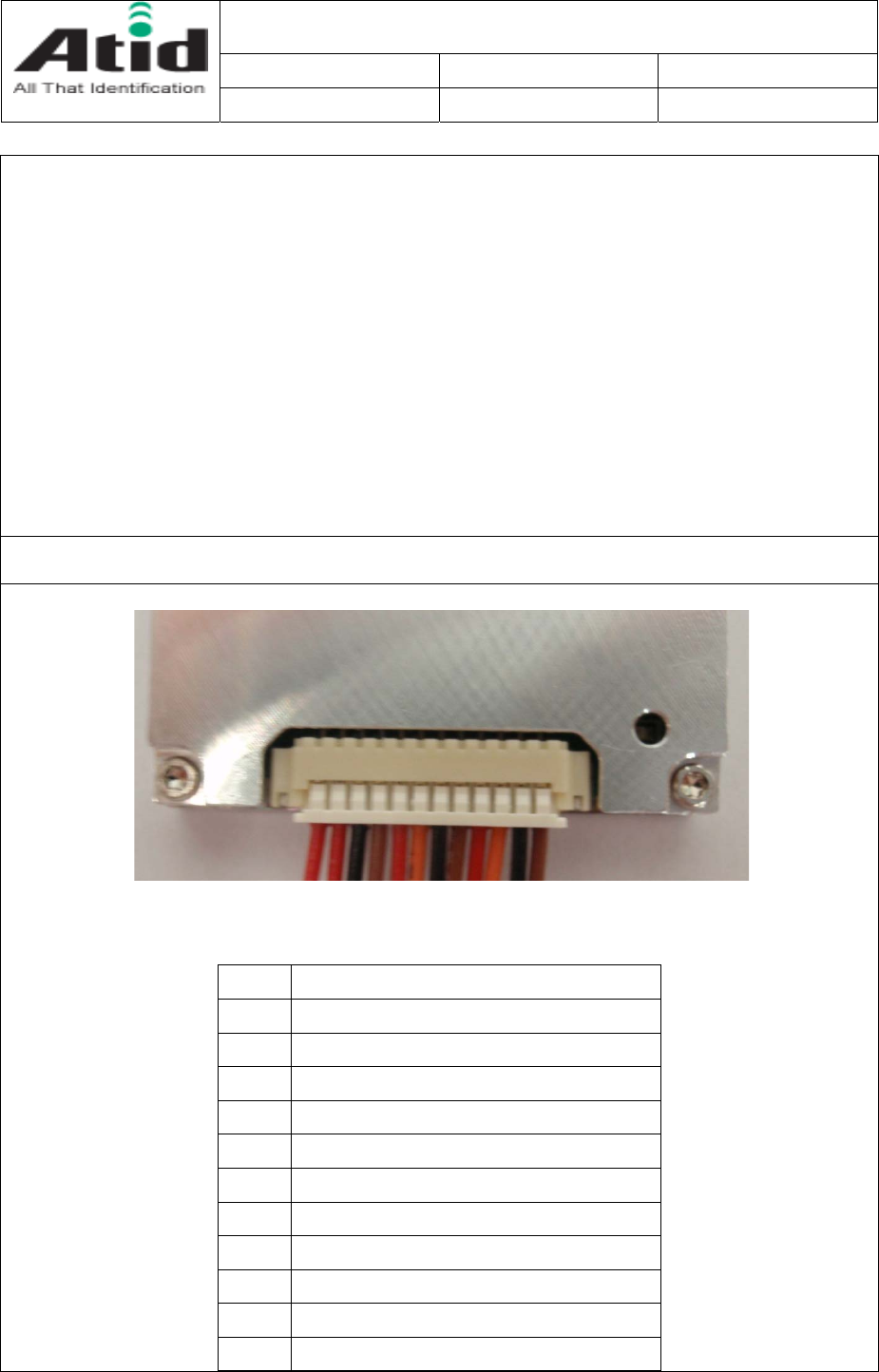
3. Reader Description
상태 표시 LED
ANT Port
DATA LED : The Red LED will twinkle when
the reader is receiving data from a tag.
ANT Port : Connect RF Cable
to reader module and ANT
Interface connector :
Supply voltage and interface with a host
system(PC, PDA…) via UART.
AT-R2000-S1 User’s Manual
Company Date Version
ATID Co.,Ltd 2012-06-29 V2.06.29
7
Identification with Radio and Optical
Interface Pin-map
① ⑫
1 VCC (3.8 ~ 4.2V, typ 4V)
2 VCC (3.8 ~ 4.2V, typ 4V)
3 GND
4 GND
5 GND
6 TXD (AT-R2000-S1 HOST)
7 RXD (AT-R2000-S1 HOST)
8 PWR_ON
9 Not Used
10 Not Used
11 Not Used
12 Not Used

AT-R2000-S1 User’s Manual
Company Date Version
ATID Co.,Ltd 2012-06-29 V2.06.29
8
Identification with Radio and Optical
4. Reader Specification
Reader Performance (KOREA, USA, EUROPE, etc)
Description Value
MODEL AT-R2000-S1
Architecture UHF RFID Reader Module
Protocol EPC Gen2(ISO 18000-6C)
Frequency 917.3MHz to 920.3MHz(Korea)
860MHz to 960MHz (Customizable)
Max Tx Power 30dBm±1dBm (1W)
Power control 5dBm to 30dBm (1dB step)
Hopping Channels 6 (Korea), 50(USA), 4(EUROPE)
Channel Spacing 600KHz (Korea, EUROPE),
500KHz(USA)
Channel Dwell time < 0.4 seconds
Modulation Method PR-ASK
Supply voltage 3.8 ~ 4.2V (typ. : 4V)
Max Current (max. power) < 1.4A
Tag Read Distance(Max.) <10m
Operating Temperature -10℃ to +50℃
LED Indicators Data
Signaling UART, Baud rate(115200bps)
Interface
Host connector
Part No. : 12505WR-12
Manufacturer : Yeonho Electronics
ANT Connector
Part No. : CMJ-S00
Manufacturer : Giga Lane
Physical Dimension
SIZE 36mm × 41mm × 8mm
Weight 16g
AT-R2000-S1 User’s Manual
Company Date Version
ATID Co.,Ltd 2012-06-29 V2.06.29
9
Identification with Radio and Optical
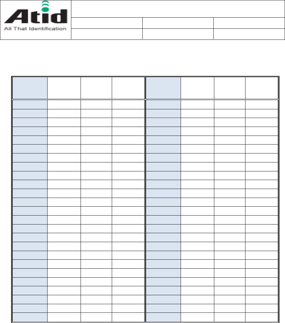
Channel number & Frequency table
CHANNEL
NO. KOREA USA EUROPE CHANNEL
NO. KOREA USA EUROPE
0 917.3 902.75 865.7 25 915.25
1 917.9 903.25 866.3 26 915.75
2 918.5 903.75 866.9 27 916.25
3 919.1 904.25 867.5 28 916.75
4 919.7 904.75 29 917.25
5 920.3 905.25 30 917.75
6 905.75 31 918.25
7 906.25 32 918.75
8 906.75 33 919.25
9 907.25 34 919.75
10 907.75 35 920.25
11 908.25 36 920.75
12 908.75 37 921.25
13 909.25 38 921.75
14 909.75 39 922.25
15 910.25 40 922.75
16 910.75 41 923.25
17 911.25 42 923.75
18 911.75 43 924.25
19 912.25 44 924.75
20 912.75 45 925.25
21 913.25 46 925.75
22 913.75 47 926.25
23 914.25 48 926.75
24 914.75 49 927.25
AT-R2000-S1 User’s Manual
Company Date Version
ATID Co.,Ltd 2012-06-29 V2.06.29
10
Identification with Radio and Optical
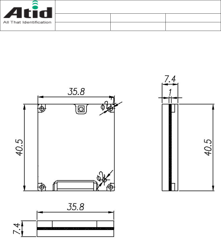
Mechanical Dimension

AT-R2000-S1 User’s Manual
Company Date Version
ATID Co.,Ltd 2012-06-29 V2.06.29
11
Identification with Radio and Optical
5. How to Run AT-R2000-S1 Sample Program
1. Windows XP/7
1.1 File name :
Reader@Express V3.2.24.zip
1.2 Simple use :
0. Add bluetooth device (Reader), and confirm relevant communication port in device
manager.
1. Decompress the file. Execute reader@express.exe.
2. Designate communication port → Select from combo box located at top upper left side.
3. Click [OPEN] button → It is right below the combo box located at upper left side
4. If it is normally connected
“RFID_OPEN() = 0 OK” is displayed in list box.
5. If you click [INVENTORY MULTIPLE] button then it starts to read tag (Inventory).
If tag is recognized,
Tag ID is displayed in list box → the latest one will be displayed at the most top.
Total number of readers is displayed → It is displayed at just upper left side of list
box in small size.
Number of tags is displayed → It is displayed at just upper right side of list box in
large size.
6. If you click [StopOperation] button then it stops to read tag (Inventory).
1.3 Notes :
Use it by setting POWER value as below 27 in upper combo box.
2. Android
2.1 File name :
AndroidSample.zip
2.2 Simple use :
It is SDK sample program for developers therefore it is not registered in the market.
You can directly install it in PC in following method.
1. Prepare Android phone and relevant data communication cable.
2. Download USB driver of relevant phone from Android phone manufacturer’s homepage and
install it in your PC.
3. Connect the phone to PC using data communication cable.
At this time, relevant drivers can be additionally installed through internet.
4. Execute command prompt (cmd.exe), and move to decompressed folder.
5. If you input as follows and execute it then it will be installed.
adb install -r ReaderApiBlueDemo.apk
You can connect with bluetooth reader in following method.

AT-R2000-S1 User’s Manual
Company Date Version
ATID Co.,Ltd 2012-06-29 V2.06.29
12
Identification with Radio and Optical
1. If you select [Search] in [Option menu],
then the window to select bluetooth device appears.
Already paired devices are appeared on upper part.
Because you must search new device therefore click [Scan for devices]
Select the device name “Blue Angel” among searched devices at the lower part.
2. Only when you connect first time,
Pairing process is progressed – PIN number is “0000”.
In most cases, it is connected normally after pairing.
3. Sometimes, it is not connected after pairing,
[Option menu]→[Search]→Select “Blue angel” in paired devices.
If you click [Inventory] button then it starts to read tag (Inventory).
If tag is recognized
Tag ID is displayed in list box → you can find the latest one on first top.
If you click [StopOperation] button then it stops to read tag (Inventory).

AT-R2000-S1 User’s Manual
Company Date Version
ATID Co.,Ltd 2012-06-29 V2.06.29
13
Identification with Radio and Optical
Appendix I : FCC Certification Requirements
1. Caution
Any changed or modifications not expressly approved by the party responsible for compliance
could void the user`s authority to operate this equipment.
2. OEM installation guide
I. OEM integrators must be instructed to ensure that the end-user has no manual
instructions to remove or install the module.
II. This module is to be installed only in mobile of fixed devices.
▪ Mobile device: The devices is to be generally used in such a way that a separation
distance of at least 20cm is normally maintained between the transmitter`s radiating
structures and the body of the user or nearby persons.
▪ Fixed devices: The device is physically secured at one location and is not able to
be easily moved to another location.
III. To ensure compliance with all non-transmitter functions the host manufacturer is
responsible for ensuring compliance with the module(s) installed and fully operational.
IV. To satisfy FCC exterior labeling requirements, the following text must be placed on
exterior of the end product.
V. An additional permanent label referring to the enclosed module: “Contains Transmitter
Module FCC ID: XYZMODEL1” or “Contains FCC ID: XYZMODEL1” must be used. The
host OEM user manual must also contain clear instructions on how end users can find
and/or access the module and the FCC ID.
3. FCC RF exposure requirements
The antenna used with this module must be installed to provide a separation distance of at
least 20cm from all persons, and must not transmit simultaneously with any other antenna or
transmitter except in accordance with FCC multi-transmitter product procedures.
4. FCC authorization for this module
If this module is installed in portable devices or the different antenna configurations are used,
the FCC authorizations are no longer considered valid and FCCID for module cannot be used
on the final product. And the OEM installer will be responsible for re-evaluating the final
product including this module and obtaining separate FCC authorization.

AT-R2000-S1 User’s Manual
Company Date Version
ATID Co.,Ltd 2012-06-29 V2.06.29
14
Identification with Radio and Optical
5. Information for importation of radio frequency devices in to the
United States.
To ensure compliance with all non-transmitter functions the host manufacturer is responsible for
ensuring compliance with the module(s) installed and fully operational. For example, if a host
was previously authorized as an unintentional radiator under the Declaration of Conformity
procedure without a transmitter certified module and a module is added, the host manufacturer is
responsible for ensuring that the after the module is installed and operational the host continues
to be compliant with the Part 15B unintentional radiator requirements.
Please see CFR47 Part 2 Subpart J Equipment Authorization Procedures, KDB784748 D01 v07, and
KDB 997198.
6. User Information
This device complies with Part 15 of the FCC`s Rule. Operation is subject to the following
to conditions;
1. This device may not cause harmful interference, and
2. This device must accept any interference received, including interference that may cause
undesirable operation.
This equipment has been tested and found to comply with the limits for a Class B digital
device, pursuant to part 15 of the FCC Rules. These limits are designed to provide reasonable
protection against harmful interference in a residential installation. This equipment generates,
uses and can radiate radio frequency energy and, if not installed and used in accordance with
the instructions, may cause harmful interference to radio communications. However, there is
no guarantee that interference will not occur in a particular installation. If this equipment
does cause harmful interference to radio or television reception, which can be determined by
turning the equipment off and on, the user is encouraged to try to correct the interference
by one or more of the following measures:
- Reorient or relocate the receiving antenna.
- Increase the separation between the equipment and receiver.
- Connect the equipment into an outlet on a circuit different from that to which the
receiver is connected.
- Consult the dealer or an experienced radio/ TV technician for help.