ATIO System VM15UAATP-151 TABLET PC User Manual VM15UA
ATIO System, Inc. TABLET PC VM15UA
USERS MANUAL
DRAFT
VM15UA
User’s Guide
Revision 1.0
September , 2003
ATIO SYS, INC.
DRAFT
- ii - VM15UA User’s Guide Revision 1.0
Copyright Notice
No part of this manual, including the products and software described in it,
may be reproduced, transmitted, transcribed, stored in a retrieval system, or
translated into any languages in any forms or by any means, except
documentation kept by the purchaser for backup purposes, without the
express written permission of ATIO System, Inc. (FIC Group).
Copyright@ 1999 ATIO System, Inc. All rights reserved.
No part of this manual, including the products and software described in it.
Trademarks
Pentium® is a registered trademark of Intel Corporation.
The following are trademarks or registered trademarks of their respective
companies: IBM, Intel, AMD, Cyrix, Award, AMI, Microsoft, Windows,
Windows NT, Novell, SCO, PC/104, PICMG, ALI, UMC, SMC, Winbond.
Products mentioned in this manual are mentioned for identification
purposes only. All names of products or services appearing in this manual
are the trademarks or registered trademarks of their respective organizations
and companies.
Liability
This User Guide is composed to assist system manufacturers and end
users in setting the Single Board Computer (SBC). ATIO provides this
guide “AS IS” without warranty of any kind, either express or implied,
including but not limited to the implied warranties or conditions of
merchantability or fitness for a particular purpose. In no events shall ATIO,
its directors, officers, employees or agents be liable for any indirect, special,
incidental or consequential damages (including damages for loss of profits,
loss of business, loss of use or data, interruption of business and the like),
even if ATIO has been advised of the possibility of such damages arising from
any defects or errors in this manual or product.
Specifications and information contained in this manual are furnished for
DRAFT
Web site: www.atiosys.com
VM15UA User’s Guide Revision: 0.91 - iii -
informational use only, and are subject to change at any time without
notice, and should not be construed as a commitment by ATIO. ATIO
reserves the right to make revisions to this publication without the
obligation to notify any persons or entities of any changes. ATIO assumes
no responsibility or liability for any errors or inaccuracies that may appear
in this manual, including the products and software described in it.
Others
Please inform your dealer immediately should there be any incorrect,
missing or damaged parts.
Please retain the carton, including the original packing materials. Repack
the product in the original way in case there is a need to return it to the
manufacturer for repairing.
Products warranty or service will not be extended if: (1) the product is
repaired, modified or altered, unless such repair, modification or
alternation is authorized in writing by ATIO; or (2) the serial number of
the product is defaced or missing.
Safety Precautions
• Follow the messages hereinafter to protect your systems from damage
on all occasion.
• Touch a grounded metal object to discharge the static electricity in
your body (or ideally, wear a grounded wrist strop).
• Stay safe from the electric shock. Don’t touch any components of this
card when the card is on. Always switch off power when the system is
not in use.
• Disconnect power when changing any hardware device; For instance,
when you connect a jumper or install any cards, a surge of power may
damage the electronic components or the whole system.
Product Name: VM15UA
Document Version: Version 1.0
Release Date: December, 2003
Printed in Taiwan
DRAFT
- iv - VM15UA User’s Guide Revision 1.0
ATIO System, Inc.
Sales:
ATIO System. Inc.(Taiwan Headquarter):
Phone: 886-2-32343089
Fax: 886-2-22269623
8F-10, No. 351, Chung Shan Rd., Sec. 2, Chung Ho City, Taipei, Taiwan 235
atio@atiosys.com
technical@atiosys.com
sales@atiosys.com
ATIO System, Inc.(North America Branch):
Phone: 1-818-407-4965
Fax: 1-818-407-4966
21540 PRAIRIE STREET, UNITA, CHATSWORTH, CA 91311 USA
charlesc@goformosa.com
NEOTEK SYSTEM.Inc (China Branch - Shenzhen Office):
Phone: 86-755-82949074
Fax: 86-755-82949132
Shenzhen Futian fortune Xinwen Road 59 Shenmao trading centre 11G China 518034
customer@atio.com.cn
NEOTEK SYSTEM, Inc (China Branch - Shanghai Office):
Phone: 86-21-64152302
Fax: 86-21-64455796
522 Electric Power Bldg. 430 Xujiahui Lu, Shanghai China 200025
customer@atio.com.cn
NEOTEK SYSTEM.Inc (China Branch - Beijing Office):
Phone: 86-10-62985337
Fax: 86-10-62985292
9/F, Block A, XinxiluTower, No.26, Xinxilu Street Shangdi, Haidian, Beijing, China 100085
customer@atio.com.cn
NEOTEK SYSTEM.Inc (China Branch - Chengdu Office):
Phone: 86-28-85234103
Fax: 86-28-86310358
Rm 701,Block B, Nan Yi Duan 20,YiHuan Road, ChengDu, SiChuan,China 610041
customer@atio.com.cn

DRAFT
Web site: www.atiosys.com
VM15UA User’s Guide Revision: 0.91 - v -
Table of Contents
1 SPECIFICATION ........................................... 7
1.1 Board Specification………………………………………7
1.2 System Specifications………………………………..
9
1.3 LCD Specifications……………………………………..10
1.3.1 OVERVIEW………………………………………………….10
1.3.2 FEATURES…………………………………………………..10
1.3.3 GENERAL SPECIFICATI0NS………………………..10
2. HARDWARE CONFIGURATION...................... 11
2.1 How to Set the Jumper 11
2.2 Jumper setting 12
2.3 Board Dimension 13
2.4 System Dimension 14
2.5 Jumper, Connector & Socket List 14
2.6 System configuration 16
2.6.1 Hardware……………………….…………………………………16
2.6.2 Software………………………………………………16
DRAFT
FEDERAL COMMUNICATIONS COMMISSION
INTERFERENCE STATEMENT
This equipment has been tested and found to comply with the limits for a Class B
digital device, pursuant to Part 15 of the FCC Rules. These limits are designed
to provide reasonable protection against harmful interference in a residential
installation. This equipment generates, uses and can radiate radio frequency
energy and, if not installed and used in accordance with the instructions, may
cause harmful interference to radio communications. However, there is no
guarantee that interference will not occur in a particular installation. If this
equipment does cause harmful interference to radio or television reception,
which can be determined by turning the equipment off and on, the user is
encouraged to try to correct the interference by one or more of the following
measures:
--Reorient or relocate the receiving antenna.
--Increase the separation between the equipment and receiver.
--Connect the equipment into an outlet on a circuit different from that to which
the receiver is connected.
--Consult the dealer or an experienced radio/TV technician for help.
CAUTION:
Any changes or modifications not expressly approved by the grantee of this
device could void
the user's authority to operate the equipment.
FCC RF Radiation Exposure Statement
This equipment complies with FCC RF radiation exposure limits set forth for an
uncontrolled environment. This equipment should be installed and operated with
a minimum distance of 20cm between the radiator and your body.
Web site: www.atiosys.com
V M 1 5 U A U s e r ’ s G u i d e R e v i s i o n : 0 . 9 1
DRAFT
Web site: www.atiosys.com
VM15UA User’s Guide Revision: 0.91 - 7 -
1. SPECIFICATION
1.1 Board Specification
Processor : VIA C3 1G Nehemiah or Eden serial CPU
System Memory / RAM : One SODIMM socket up to 512 MB
Display Type : TFT LCD 15.1” and Max resolution
1024x768
VGA connector : One DB-15 VGA connector
Wireless Lan : Built-in Wireless Lan
Card Reader : Built-in Card Reader
Ethernet Connectors : Two RJ-45 connectors, supports 10/100
Base-T interface, wake on LAN, Boot ROM
and PXE functions
PC-104+ Interface : Built-in PC-104+ interface
HDD : IDE HDD Interface (2.5” HDD bay)
Compact Flash : Built-in Compact Flash Type I and II
SRAM : Built-in 4MB SRAM
Touch sensor Built-in 3M dynapro Touch sensor
(8-wires resistor type)
Serial Port
: Four COM ports with ESD protact,
COM1 RS-232 D-sub 9pin Male connector,
COM2 RS-232 D-sub 10pin Male
connector; pin 10 as +5V
COM3 RS-232/422/485(Auto-sensing)
D-sub 25pin Male connector,
COM4 RS-232 2x6,2.54mm pin header
and (optional) for Salt Touch Senser
controller controlled by switch.
Parallel Port : One multi-mode parallel port
( SPP/EPP/ECP ) DB-25 connector
Keyboard/Mouse connector
: Tow 6-pin mini-DIM PS/2 keyboard and
mouse connectors
Universal Serial Bus : Supports two A-type USB port connectors
Power Supply : 150W power supply
Operating Temperature : 0°C ~ 45°C
Storage Temperature : -20°C ~ 70°C
Humidity : 5% ~ 80% RH, non-condensing
Dimensions : 376.8*310.5 mm +/- 0.5mm
Net weight : ? g (? pounds )
EMI/EMS
: Meet CE and FCC class A regulation, test
service not include in design and layout
DRAFT
- 8 - VM15UA User’s Guide Revision 1.0
charge
Meet the class B standard
Other function : Support USB device boot
up(FDD,HDD,CD-ROM)
Support Dual VGA
Host bridge : VIA VT8605 [ProSavage PM133]
PCI bridge : VIA VT8605 [PM133 AGP]
ISA bridge : VIA VT82C686 [Apollo Super South] (rev
40)
IDE interface : VIA VT82C586B PIPC Bus Master IDE (rev
06)
USB controller : VIA USB (rev 1a)
USB controller : VIA USB (rev 1a)
Bridge : VIA VT82C686 [Apollo Super ACPI] (rev
40)
Multimedia audio controller
: VIA VT82C686 AC97 Audio Controller (rev
50)
Module: via82cxxx_audio
Ethernet controller : Intel 82559ER (rev 09)
Module: eepro100
Ethernet controller : Realtek RTL-8139/8139C/8139 C+ (rev
10)
Module: 8139too
VGA compatible controller : S3 VT8603 [ProSavage PN133] AGP4X
VGA Controller (Twister) (rev 02)
Driver: Savage
VendorName: S3 Savage4 (generic)
Resolution: 1024*768 (16bit)
Wireless LAN : VendorName: Intersil
Module: prism2_usb
Serial Port
: COM1: ttyS0 at 0x3f8 (irq=4) is a
16550A
COM2: ttyS1 at 0x2f8 (irq=3) is a
16550A
COM3: ttyS2 at 0x3e8 (irq=10) is a
16550A
COM4: ttyS3 at 0x2e8 (irq=11) is a
16550A
We should set IRQ for COM3 and COM4
under Linux.
TouchScreen : VendorName: Penmount
Driver: penmount
Device: /dev/ttyS3 (where ttyS3 = COM4
which is for Salt Touch Senser controller.)
The installation guide for penmount driver
BIOS setup : 1. Panel Type as 07 (1024x768 resolution
DRAFT
Web site: www.atiosys.com
VM15UA User’s Guide Revision: 0.91 - 9 -
mode)
2. Setting <Load fail-safe default> or
<Load Optimized
default> in the BIOS menu to load the
bios default value.
1.2 System Specification
CPU : VIA C3 1G Nehemiah or Eden serial CPU
Disk Drive Housing : Room for one 2.5” HDD
Dimension : 376.8*310.5 mm
Weight : ~10kg
Memory : Supports up to 512MB SODIMM(144pin)
FDD : Supports Notebook type FDD connector
Network(Lan) : 10/100 Base-T Ethernet Interface
Smart Card Reader : UIC HCR330 smart card reader
Wireless : Supports IEEE802.11b wireless solution
Compact Flash : Built-in Compact Flash Type I and II
SRAM : Built-in 512KB SRAM
Touch sensor Built-in 3M dynapro Touch sensor
IO ports
: - 4 serial ports: RS-232 x3,
RS-232/422/485x1
- 1 parallel port, 2 USB ports
- 1 PS2 keyboard and mouse interface
- Mic-in(optional), Speaker-out
Power Supply
Output Rating : 90W max
Input voltage : 100~240Vac, auto switch @ 50~60Hz
Output voltage : +5V@ 4A; +12V@2A
Battery : Supports two hours when system is fully
running.
Environment Spec.
Operating Temperature : 0°C ~ 45°C(32~113℉)
Storage Temperature : -20°C ~ 70°C
Relative Humidity : 10% ~ 90% RH, non-condensing
EMC
Meet CE and FCC class B
Safety : UL, CE
DRAFT
- 10 - VM15UA User’s Guide Revision 1.0
1.3 LCD Specification
1.3.1 OVERVIEW
M150X4-L06 is a 15.0” TFT Liquid Crystal Display module with 2
CCFL Backlight units and 20 pins LVDS interface. This module
supports 1024 x 768 XGA mode and can display 16.2M colors.
The optimum viewing angle is at 6 o’clock direction. The inverter
module for Backlight is not built in.
1.3.2 FEATURES
-XGA (1024 x 768 pixels) resolution
- DE(Data Enable) only mode
- LVDS Interface with 1pixel/clock
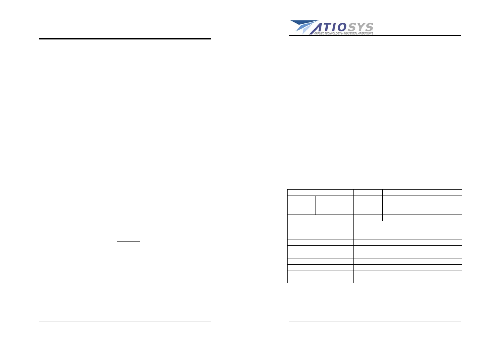
1.3.3 GENERAL SPECIFICATI0NS
Item Min. Typ. Max. Unit
Horizontal(H) 320.5 321.0 321.5 mm
Vertical(V) 244.9 245.4 245.9 mm
Module
Size Depth(D) - 9.7 10 mm
Weight - - 930 g
Item Specification Unit
Active Area 304.128(H) x 228.096(V) (15.0”
diagonal) mm
Bezel Opening Area 307.5(H) x 231.4(V) mm
Driver Element a-Si TFT active matrix -
Pixel Number 1024 x R.G.B. x 768 pixel
Pixel Pitch 0.297(H) x 0.297(W) mm
Pixel Arrangement RGB vertical stripe -
Display Colors 16,194,277 color
Transmissive Mode Normally white -
DRAFT
Web site: www.atiosys.com
VM15UA User’s Guide Revision: 0.91 - 11 -
2. HARDWARE CONFIGURATION
2.1 How to Set the Jumper
In order to select the operation modes of your system, configure
and set the jumpers on the your Embedded SBC to match the need
of your application. To set a jumper, a black plastic cap containing
metal contacts is placed over the jumper pins as designated by the
required configuration as listed in this section. A jumper is said to
be “ on ” or “ 1-2 ” when the black cap has been placed on two of
its pins, as show in the figure below:
A pair of needle-nose pliers is recommended when working
with jumpers. If you have any doubts about the best
hardware configuration for your application, contact your local
sales representative before you make any changes. In general,
you simply need a standard cable to make most connections.
DRAFT
- 12 - VM15UA User’s Guide Revision 1.0
2.2 Jumper Setting

DRAFT
Web site: www.atiosys.com
VM15UA User’s Guide Revision: 0.91 - 13 -
2.3 Board Dimension
DRAFT
- 14 - VM15UA User’s Guide Revision 1.0
2.4 System Dimension

DRAFT
Web site: www.atiosys.com
VM15UA User’s Guide Revision: 0.91 - 15 -
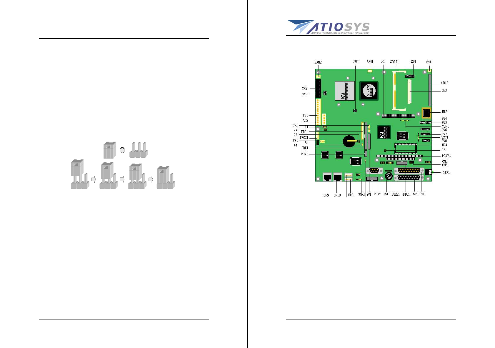
2.5 Jumper, Connector & Socket List
Jumper:
COMS Reset Connector.................................... JP1
Connector:
System FAN Connector .................................... CN1
System FAN Connector .................................... CN2
COM2 Connector ............................................ CN3
422 / 485 Connector ....................................... CN4
IDE LED Connector ......................................... CN5
External Power Button Connector (For ATX Power)CN6
Reset Button Connector................................... CN7
168-PIN SDRAM DIMM Connector………………………….CN8
CRT VGA Connector ........................................ CN9
COM1 Connector ............................................ CN10
IR Connector ................................................. CN11
Digital I/O Connector ...................................... CN12
IDE1 44pin 2.0mm Connector .......................... CN13
IDE1 44pin 2.0mm Connector .......................... CN14
Floppy Disk 34pin 2.00mm Connector ............... CN15
Keyboard / Mouse Connector............................ CN17
USB Connector............................................... CN18
USB Connector............................................... CN19
Power LED Connector ...................................... CN20
LAN LED Connector......................................... CN21
Switch:
Switch For COM2(RS232/422/485)……………………….SW1
DRAFT
- 16 - VM15UA User’s Guide Revision 1.0
2.6 System configuration
2.6.1 Hardware
- CPU Board part number: C708-VMB10-100
- CPU: using VIA C3 1G Nehemiah (133x7.5), but the CPU front
side bus set as 100MHz by 7.5 ratios.
- 2.5” HDD (Model#: IC25N020ATCS04-0/20G)
- LCD: LM151X4-(A3)
- Inverter: QF61V4
- Touch sensor: 3M MicroTouch 15.0” Model#: RES15.0-PL8
- CPU cooler: AVC C4010T12H DC12V 0.1A
- SODIMM: V-DATA 256MB PC-133 RC56S1617TA0-13AC
- Compact Flash: PQI 128MB
- Power supply: FSP150-50PL1
- Wireless: ActionTec
- SRAM is modified from 2MB to 512KB.
2.6.2 Software
- Linux Ret Hat 8.0/Kernel version: 2.4.18-14
- Test items
a. X11scaling 30 minutes.
b. True Image(Backup and Restore), using on-board 82559ER
LAN.
c. Wireless LAN test.
d. Memory test: 2hrs
e. CPU test: X11perf 4hrs
f. HDD test: Bonniett 2hrs