ATOP Technologies AT705RFID Picktag User Manual AT7053KRF USER MANAUAL
ATOP Technologies, INC. Picktag AT7053KRF USER MANAUAL
Contents
- 1. User Manual (AT707A4KRF)
- 2. User Manual (AT7053KRF)
- 3. User Manual (AT705233KRF)
User Manual (AT7053KRF)
ABLEPick pick-to-light user manual
1
Introduction
ABLEPick is an advanced paperless picking system providing an innovative, streamlined
and cost-effective Pick-to-light solution to simplify the order fulfillment process in warehouse
or distribution center. ABLEPick use a state-of-the-art and light-directed technology to
maximize the picking productivity, speed and accuracy in different picking operation.
Products Features
- Ethernet architecture, follow up the standard TCP/IP communication protocol.
- CABLELESS pick tags.
- Versatility in different operating modes configuration.
- Easy to install, maintain and upgrade.
- Wide operating temperature range (from –25oC to 40oC).
Benefit
- Paperless picking process.
- Streamline the order fulfillment process.
- Increase picking productivity dramatically.
- Accuracy assured: virtually eliminate picking error, below 0.1%.
- Easy to use: picker can usually be trained in less than 1/2 hour.
- Strengthen management control: on-line picking data control, easy to prompt the material
shortage.
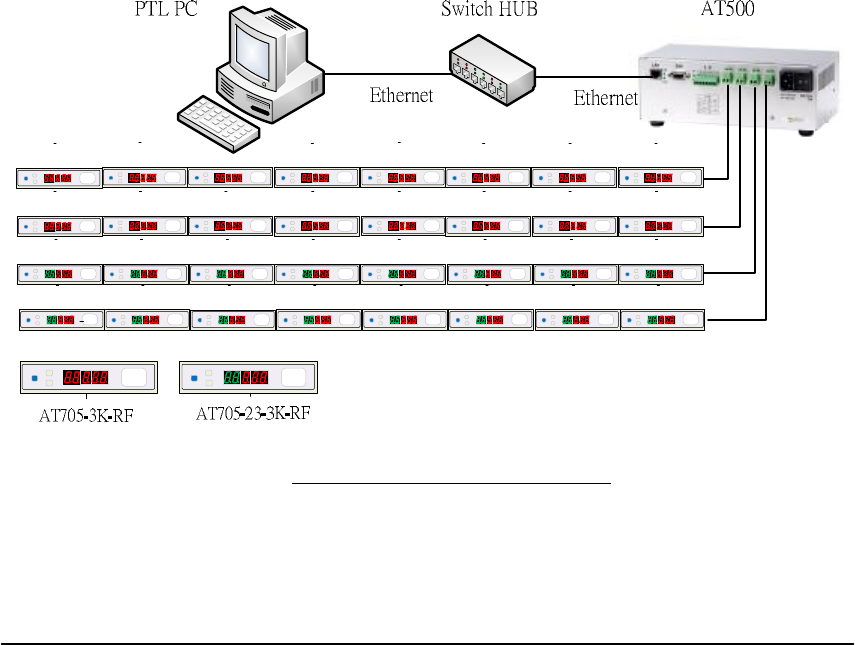
Figure ABLEPICK Architecture

ABLEPick pick-to-light user manual
2
. PICK-TO-LIGHT OPERATION
Work flow of pick-to-light system: Below simply describe the basic operation
Data entry
Picking list files can be downloaded to the LAN server or PC from WMS/MIS host. These
files will be read and merged into pick-to-light picking list database.
Control and communication
Pick-to-light software will monitor picking flow and offer real-time information on the
screen.
Light up
Different models of picking tags light up to indicate what order, which location and how
many pieces to be picked.
Pick and confirm
The picker picks the quantity as tag shows or modifies the quantity directly from tag, then
push the button to confirm this action.
2 Complete
Completion indicator will light up and buzz after all jobs in a zone are done. Push the
button to confirm this action and move this order to the next available zone.
ABLEPick pick-to-light user manual
3
ABLEPick Hardware
TCP/IP controller
AT500
TCP/IP controller is a data transmission medium between picking control PC and all the
picking devices. Which is Ethernet architecture product, following up the standard TCP/IP
communication protocol to communicate with the host PC. Each controller has 4 output
channels to connect to the picking devices, each channel can connect to maximum 30
devices. So one TCP/IP controller can connect to maximum 120 pcs of picking devices.
Specifications:
- To host computer communication interface :
IEEE 802.3 Base band (Ethernet)
RJ-45 Phone-jack connector x 1
Transmission speed: 10 / 100 Mbps
Communication protocol : TCP/IP
- Input Voltage and current: AC 115/230 V, 50/60 Hz
- Power supply : Maximum 320 Watt
- Temperature : 0 °C to 50 °C operating, -20 °C to 70 °C storage
- Humidity: 90% non-condense
- Dimension: Aluminum case 250(L)*130(W)*100(H)mm
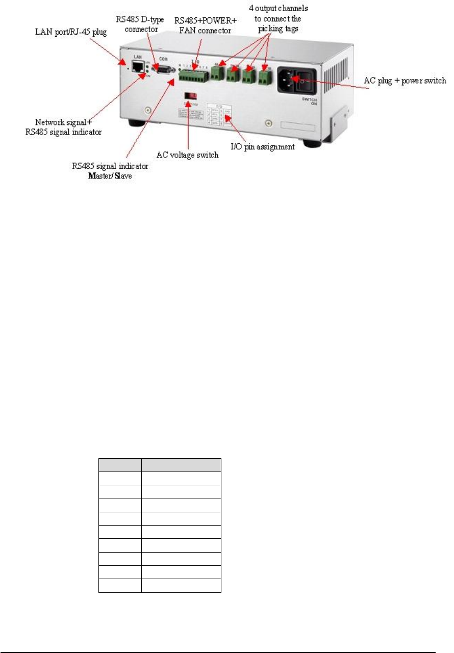
Pin assignment:
RS485 D-type 9 pin female connector
pin Defin.
1 -
2 GND
3 DATA1-
4 RTS-
5 -
6 -
7 -
8 DATA+
9 RTS+

ABLEPick pick-to-light user manual
4
I/O port pin assignment
pin Defin.
1 RTS+
2 RTS-
3 DATA+
4 DATA-
5 GND
6 +12V /3A
7
8 Fan switch, 45 C auto power on
AT500’s IP configuration
AT500’s default IP address is “10.0.50.100” and sub-mask is “255.255.0.0”. You can use
ATOP’s tool “MONITOR.exe” to know and re-configure each AT500’s IP address.
Connection to TCP/IP controller (AT500)
Since AT500 has no DHCP function, so its host control PC/NB need to assign one IP
address which have to be within the same domain as the AT500. Then you can create one
TCP connection to connect it. AT500’s TCP port is 4660.

ABLEPick pick-to-light user manual
5
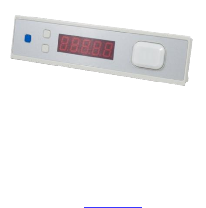
Picking Tag : AT705-3K-RF
Federal Communication Commission Interference Statement
This equipment has been tested and found to comply with the limits for a Class B digital
device, pursuant to Part 15 of the FCC Rules. These limits are designed to provide reasonable
protection against harmful interference in a residential installation. This equipment generates,
uses and can radiate radio frequency energy and, if not installed and used in accordance with the
instructions, may cause harmful interference to radio communications. However, there is no
guarantee that interference will not occur in a particular installation. If this equipment does
cause harmful interference to radio or television reception, which can be determined by turning
the equipment off and on, the user is encouraged to try to correct the interference by one of the
following measures:
- Reorient or relocate the receiving antenna.
- Increase the separation between the equipment and receiver.
- Connect the equipment into an outlet on a circuit different from that
to which the receiver is connected.
- Consult the dealer or an experienced radio/TV technician for help.
FCC Caution: Any changes or modifications not expressly approved by the party
responsible for compliance could void the user's authority to operate this equipment.
This device complies with Part 15 of the FCC Rules. Operation is subject to the following
two conditions: (1) This device may not cause harmful interference, and (2) this device must
accept any interference received, including interference that may cause undesired operation.

ABLEPick pick-to-light user manual
6
Large illuminated confirmation button.
confirmation button has 6 colors LED design, which are RED, GREEN, AMBER, BLUE,
PURPLE and INDIGO individually. The default color is RED. LED’s color can be configured
by software, which can be stored in the EEPROM.
Power on procedure
Step1: The 7-segment will show “8“ from 1st digit to last digit sequentially(from right to left).
Step2: The LED light will change color: RED, GREEN and AMBER sequentially.
Step3: Show the F/W version of the tag. For example: “U1.2”.
Step4: Show the address ID of the tag. For example: “[001]” (this is a decimal number).
Step5: Show the function configuration of the tag. The default function configuration value is
115. in decimal.
Address configuration via the buttons directly.
In a field bus, each Picking Tag must be with unique address ID.
Step1: Press the “up-count” and “down count” button at the same time, then push the
“Confirmation Button”. Then 7-segment LED display will show the address ID of the
tag. For example: “[001]”.
Step2: The 1st changeable digit will be blinking. Using the“up-count” and “down count” button
to adjust the digit to the adequate value. Or using the “Confirmation button” to switch to
next changeable digit. There are 3 digits been able to be changed.
Step3: Press the “Confirmation Button” many times to exit the address configuration. Once the
display is off, it means the node address configuration is completed.

ABLEPick pick-to-light user manual
7
Self-test function enabled
Step1: Press the “up-count” button, then “Confirmation Button” at the same time. 7-segment
LED display will show the address ID of the tag. For example: “[001]”. However, there is
no digit is blinking which is different from the address configured procedure.
Step2: Press the “Confirmation button”. The 7-segment LED display will show the baud rate of
the tag. For example: “57600” is 57600 bps. The tag will detect the baud rate of the host
and configure itself automatically.
Step3: Press the “Confirmation Button” to test the LED light and the 7-segment LED display. The
display will show “-----“, “00000”, “11111”, “22222”…...”99999” sequentially. And the LED
light also will change color: from RED, GREEN and AMBER sequentially.
Step4: Press the “Confirmation Button” to test both of the small buttons and the Confirmation
button. To press the “Confirmation button” to add a “[” character on the 7-segment LED
display”. To press the “up-count” and “down-count” button to decrease a “[” character on
the display.
Step5: Press the “Confirmation Button” many times to exit the self-testing procedure
Specification
1) 5-digits display.
2) 3 function keys.
3) 1 large illuminated confirmation button with 6-color LED.
4) RF reader.
5) Power requirements: DC12V ; 100mA
5) Operating temperature: 0 °C to 40 °C
6) Size : 200(L) * 46 (W) * 30(H) mm