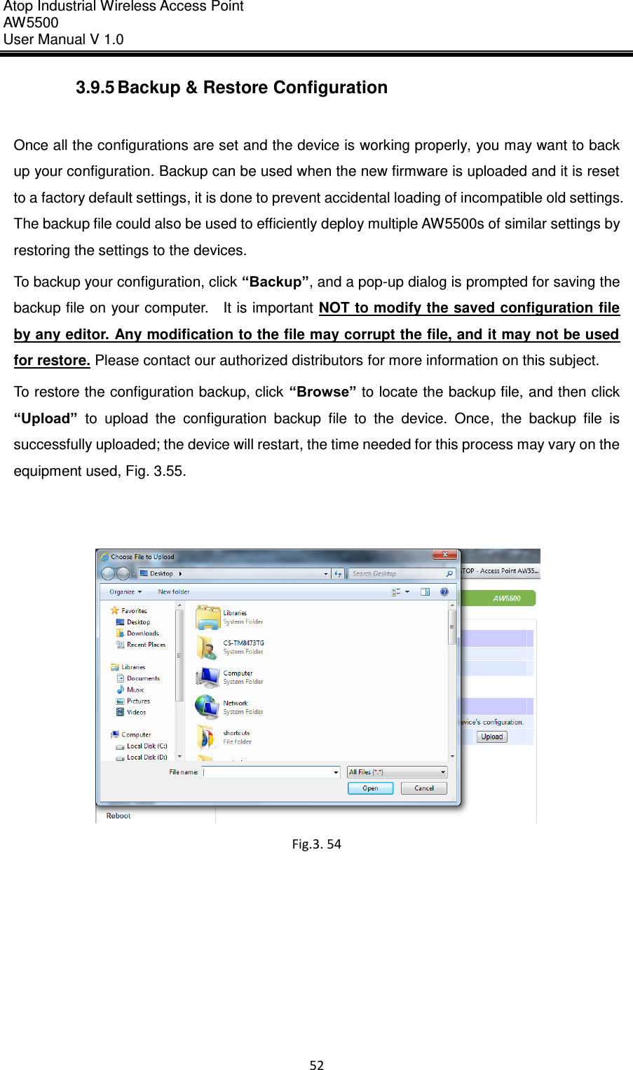
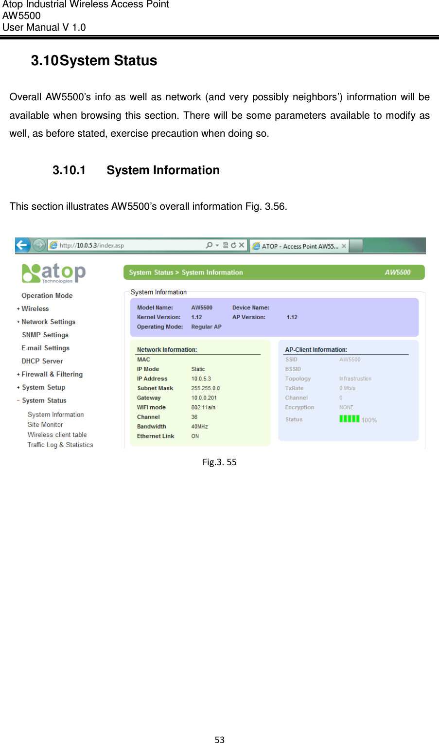
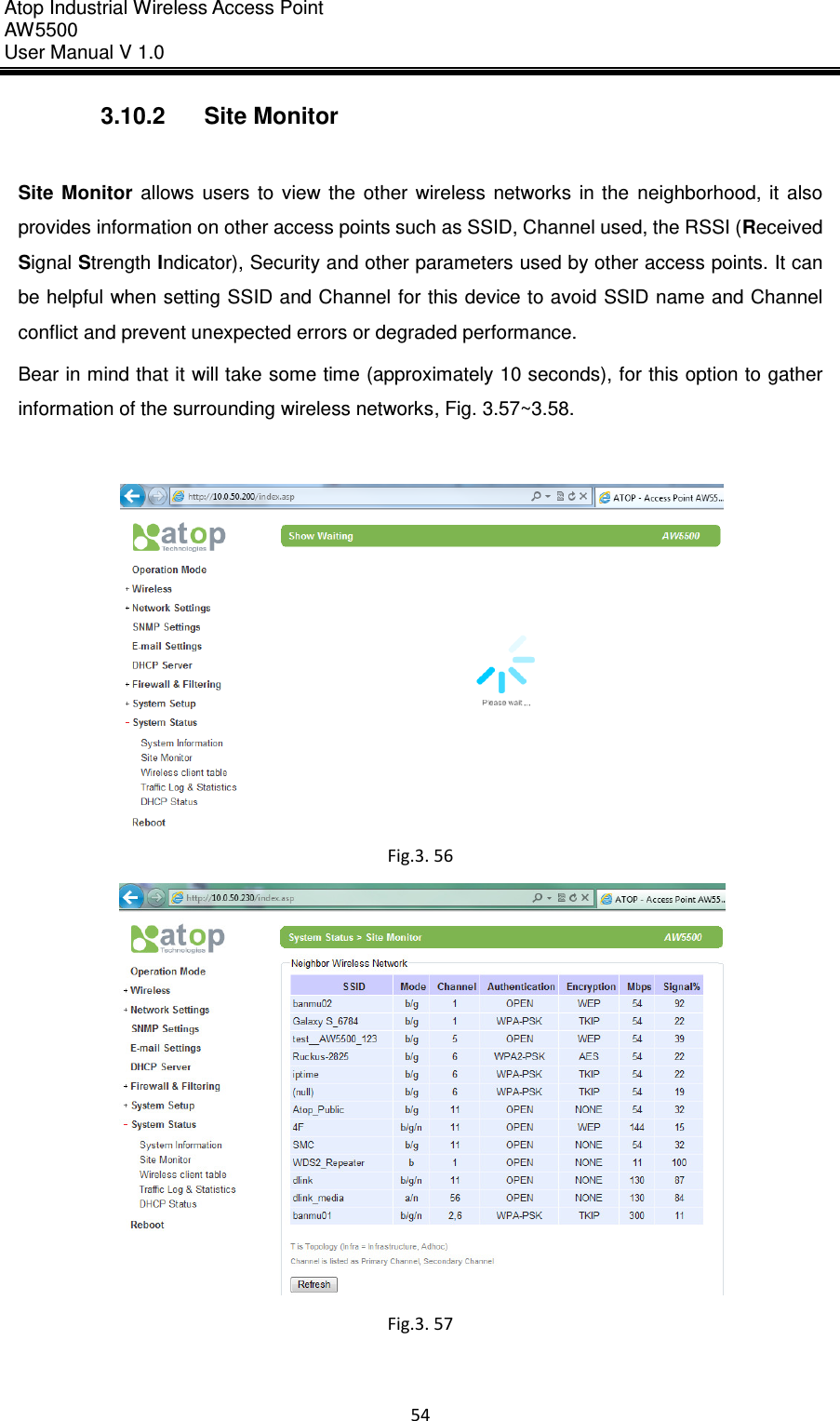
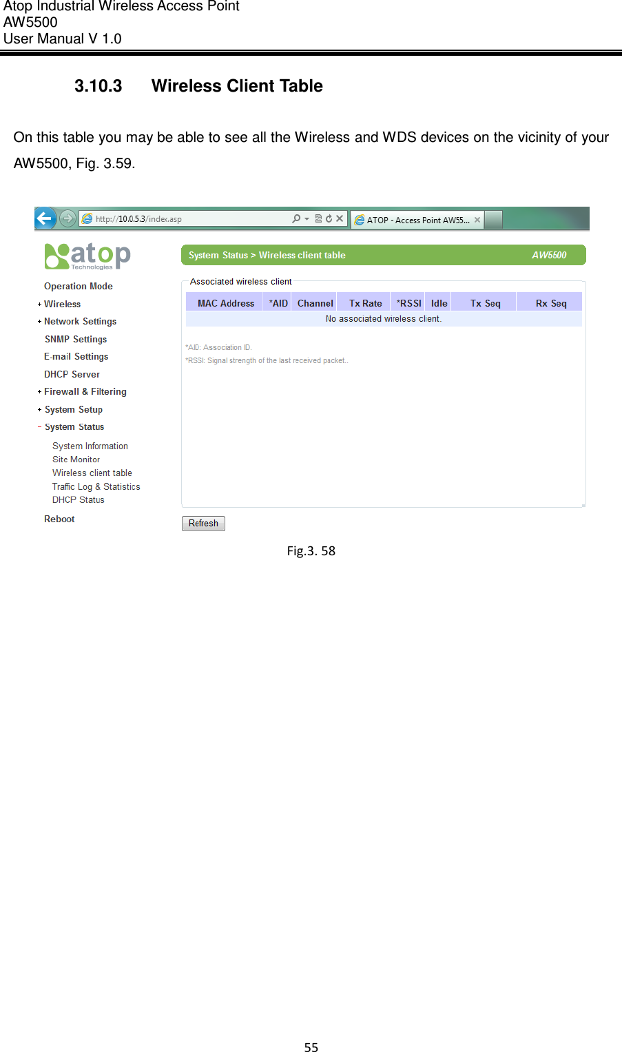
ATOP Technologies AW-SW5502 Industrial Wireless Access Point, Industrial Wireless Serial Device Server, Industrial Wireless Modbus Gateway User Manual

ATOP Technologies, INC. Industrial Wireless Access Point, Industrial Wireless Serial Device Server, Industrial Wireless Modbus Gateway

User Manual

  AW5500 Industrial Wireless Access Point User’s Manual  v. 1.0 Feb., 2012
Atop Industrial Wireless Access Point AW 5500 User Manual V 1.0                      ii Important Announcement The information contained in this document is the property of Atop Technologies, Inc. and is supplied  for  the  sole  purpose  of  operation  and  maintenance  of  Atop  Technologies,  Inc. products.  No part of this publication is to be used for any other purposes, and it is not to be reproduced, copied, disclosed, transmitted, stored in a retrieval system, or translated into any human or computer language, in any form, by any means, in whole or in part, without the prior explicit  written  consent  of  Atop  Technologies,  Inc.,  offenders  will  be  liable  for  damages.  All rights, including rights created by patent grant or registration of a utility model or design, are reserved.  Disclaimer We have checked the contents of this manual for agreement with the hardware and software described. Since deviations cannot be precluded entirely, we cannot guarantee full agreement. However, the data in this manual is reviewed regularly and any necessary corrections included in subsequent editions. Suggestions for improvement are welcome. All other product names referenced herein are registered trademarks of their respective companies.   Published and Printed by Atop Technologies, Inc. 2F, No. 146, Sec. 1, Tung-Hsing Rd. Jubei, Hsinchu 30261 Taiwan, R.O.C. Tel: 886-3-5508137   Fax: 886-3-5508131 www.atop-tech.com www.atop.com.tw  Copyright  ©  2011  Atop  Technologies,  Inc.  All  rights  reserved.  Technical  data  is  subject  to change.  All  other  product  names  referenced  herein  are  registered  trademarks  of  their respective companies.
Atop Industrial Wireless Access Point AW 5500 User Manual V 1.0                      iii Table of Contents Preface ............................................................................................................... 2 1 Introduction ................................................................................................ 5 1.1 Product Overview ........................................................................... 5 1.2 Features ........................................................................................... 5 2 Getting Started ........................................................................................... 7 2.1 Inside the Package ......................................................................... 7 2.2 Front & Power Panels .................................................................... 8 2.3 First Time Installation .................................................................... 9 2.3.1 Web Configuration Overview ............................................ 10 2.4 Factory Default Settings ............................................................... 12 3 Web Console Configuration .................................................................... 15 3.1 Administrator Login ...................................................................... 15 3.2 Overview Information ................................................................... 16 3.2.1 Secure Wireless Network .................................................. 17 3.3 Wireless Settings .......................................................................... 17 3.3.1 Basic Settings ..................................................................... 18 3.3.2 Security Settings ................................................................ 25 3.3.3 WDS Settings ...................................................................... 29 3.3.4 Advanced Settings ............................................................. 29 3.4 Network Settings ........................................................................... 31 3.4.1 LAN Interface ...................................................................... 31 3.5 SNMP Settings ............................................................................... 32 3.6 Email Settings ................................................................................ 34 3.7 DHCP Server .................................................................................. 35 3.8 Firewall & Filtering ........................................................................ 37 3.8.1 Wired MAC Filtering ........................................................... 37 3.8.2 Wireless MAC Filtering ...................................................... 39 3.8.3 Ethernet Type Filtering ...................................................... 41 3.8.4 IP Filtering ........................................................................... 43 3.8.5 Wireless Client Isolation ................................................... 44 3.9 System Setup ................................................................................. 45 3.9.1 Admin Settings ................................................................... 45 3.9.2 Date/Time Settings ............................................................. 46 3.9.3 Alert Event ........................................................................... 47 3.9.4 Firmware Upgrade .............................................................. 48 3.9.5 Backup & Restore Configuration ..................................... 52
Atop Industrial Wireless Access Point AW 5500 User Manual V 1.0                      iv 3.10 System Status ............................................................................ 53 3.10.1 System Information............................................................ 53 3.10.2 Site Monitor ......................................................................... 54 3.10.3 Wireless Client Table ......................................................... 55 3.10.4 Traffic Log &Statistics ....................................................... 56 3.10.5 DHCP Status ....................................................................... 57 3.11 Reboot and Restore Default Settings ..................................... 58 4 Operation Modes ...................................................................................... 59 4.1 Regular AP Mode ........................................................................... 59 4.2 WDS Bridge Mode ......................................................................... 62 4.3 AP Client Mode .............................................................................. 65 5 Applications .............................................................................................. 67 5.1 Basic Access Point Setup ............................................................ 67 5.2 Basic WDS Setup ........................................................................... 1 5.3 Coverage Range Extender Setup ................................................. 1 5.4 AP Client Setup............................................................................... 2 6 Specifications ............................................................................................ 3 6.1 Hardware Specification ................................................................. 3 6.2 Software Specifications ................................................................ 9 6.3 LED Indicators ................................................................................ 9 Warranty ............................................................................................................ 12
Atop Industrial Wireless Access Point AW 5500 User Manual V 1.0                      2  Preface  Purpose of the Manual This  manual  supports  you  during  the  installation  and  configuring  of  the  AW5500  Industrial Wireless Access Point only, as well  as  it explains  some technical options  available  with the mentioned  product.  As  such,  it  contains  some  advanced  network  management  knowledge, instructions, examples, guidelines and general theories designed to help users  manage this device and its corresponding software; a background in general theory is a must when reading it. Please refer to the Glossary for technical terms and abbreviations (if any).  Who Should Use This User Manual This  manual  is  to  be  used  by  qualified  network  personnel  or  support  technicians  who  are familiar  with  network  operations;  it  might  be  useful  for  system  programmers  or  network planners as well. This manual also provides helpful and handy information for first time users. For any related problems please contact your local distributor, should they be unable to assist you, please redirect your inquiries to www.atop.com.tw or www.atop-tech.com .  Supported Platform This manual is designed for the AW5500 Industrial Wireless Access Point and that model only.  Warranty Period We provide a 5 year limited warranty for AW5500 industrial wireless access point.   Manufacturers  Federal  Communication  Commission  Declaration  of Conformity Statement   Model: AW5500 NOTE:   This  equipment  has  been  tested  and  found  to  comply  with  the  limits  for a Class  A digital  device,  pursuant  to  Part  15 of  the  FCC  Rules.   These  limits are designed  to  provide reasonable  protection  against  harmful  interference  when the  equipment  is  operated  in  a commercial environment.   This equipment generates, uses, and can radiate radio frequency energy  and,  if not  installed and  used in  accordance  with  the instruction  manual,  may cause harmful interference  to  radio  communications.   Operation  of  this  equipment  in  a
Atop Industrial Wireless Access Point AW 5500 User Manual V 1.0                      3  residential area is likely to cause harmful interference in which case the user will be required to correct the interference at his own expense. This device complies with Part 15 of the FCC Rules.   Operation is    subject to the following two conditions:   (1) this device may not cause    harmful interference, and (2) this device must accept any interference    received, including interference that may cause undesired operation. This  device  and  its  antenna(s)  must  not  be  co-located  or  operating  in  conjunction  with  any other antenna or transmitter. FCC Caution: Any changes or modifications not expressly approved by the party responsible for compliance could void the user's authority to operate this equipment. For  product  available  in  the  USA/Canada  market,  only  channel  1~11  can  be  operated. Selection of other channels is not possible. This device is restricted to indoor use when operated in the 5.15 to 5.25 GHz frequency range. ※     FCC requires this product to be used indoors for the frequency range 5.15 to 5.25 GHz to reduce the potential for harmful interference to co-channel Mobile Satellite systems.  FCC Radiation Exposure Statement: This  equipment  complies  with  FCC  radiation  exposure  limits  set  forth  for  an  uncontrolled environment. This equipment should be installed and operated with minimum distance 20cm between the radiator & your body. European Community, Switzerland, Norway, Iceland, and Liechtenstein   Model: AW5500 Declaration of Conformity with regard to the R&TTE Directive 1999/5/EC   This equipment is in compliance with the essential requirements and other relevant provisions of 1999/5/EC. The following standards were applied:   EMC—EN 301.489-1 v1.4.1; EN 301.489-17 v1.2.1   Health & Safety—EN60950-1: 2001; EN 50385: 2002   Radio—EN 300 328 v 1.7.1; EN 301.893 v 1.5.1   The  conformity  assessment  procedure  referred  to  in  Article  10.4  and  Annex  III  of  Directive
Atop Industrial Wireless Access Point AW 5500 User Manual V 1.0                      4  1999/5/EC has been followed.   This  device  also  conforms  to  the  EMC  requirements  of  the  Medical  Devices  Directive 93/42/EEC.   Note  This equipment is intended to be used in all EU and EFTA countries. Outdoor use may be restricted to certain frequencies and/or may require a license for operation. For more details, contact Atop Technical Support.   European Union   This  system  has  been  evaluated  for  RF  exposure  for  Humans  in  reference  to  the  ICNIRP (International  Commission  on  Non-Ionizing  Radiation  Protection)  limits.  The  evaluation  was based on the EN 50385 Product Standard to Demonstrate Compliance of Radio Base stations and  Fixed  Terminals  for  Wireless  Telecommunications  Systems  with  basic  restrictions  or reference levels related to Human Exposure to Radio Frequency Electromagnetic Fields from 300 MHz to 40 GHz. The minimum separation distance from the antenna to general bystander is 20cm (7.9 inches).   UL Notice for Power supplier The series AW5500 products are intended to be supplied by a Listed Power Unit marked with “LPS” (Limited Power Source), or “Class 2” and output rate of 9~48 VDC, 1.0 A minimum, or use the recommended power supply listed in “Optional Accessories”.
Atop Industrial Wireless Access Point AW 5500 User Manual V 1.0                      5  1 Introduction 1.1  Product Overview  The AW5500 Wireless Access Point series is our new line of wireless products designed to provide  a  wireless  connectivity to  clients  or  mobile stations  creating  a  complete  solution for your industrial wireless networking.   As an example,  you can connect serial devices to our  Wireless Serial  Server and connect these two to a Wireless Access Point device; this example illustrates how to connect serial devices  to  a  local  area  network  or  a  backbone  network,  Figure  1.1.  The  AW5500  series provide several functionalities to support mobile and wireless networking.   Fig. 1. 1  1.2  Features  AW5500 is our latest addition to our Industrial Wireless products; its small size but powerful architecture  makes  it  a  perfect  choice  for  industrial/manufacturing  needs  in  which  size  is  a decisive  factor.  It  rewards  our  customers  with  superb  connectivity.  Among  its  many characteristics, we could mention:    Stream input/output with maximum link speed of 300Mps and throughput of 100Mps (environment dependent).   5  GHz  frequency  support  to  reduce  interference  on  2.4  GHz  with  other  wireless devices.   Client isolation to enhance security between wireless clients.   Different modes of operation:     Regular AP   WDS Bridge   AP Client
Atop Industrial Wireless Access Point AW 5500 User Manual V 1.0                      6   Caution Beginning from here there will be extreme caution exercised.   Never install or work on electrical or cabling during periods of lighting activity. Never connect or disconnect power when hazardous gases are present.  WARNING: Disconnect the power and allow to cool 5 minutes before touching.
Atop Industrial Wireless Access Point AW 5500 User Manual V 1.0                      7  2 Getting Started 2.1  Inside the Package  Inside the product purchased you will find the following items1:   Table 2. 1 Item Quantity Description AW5500 1 Industrial Wireless Access Point Antenna 2 3~5dBi antenna Terminal Block 1 3-pin terminal block Mounting kit 1 DIN-Rail kit, already mounted on the device’s back plate. Documentation + CD (Utilities) 1 Inside the CD you will find:   User’s Manual   Installation Guide  Device View © Utility              Note1: Please  notify  your sales  representative if  any  of  the  above items  is  missing  or  damaged  in  any  form  upon delivery. If your sales representative is unable to satisfy your enquiries, please contact us directly.
Atop Industrial Wireless Access Point AW 5500 User Manual V 1.0                      8  2.2  Front & Power Panels  The Front (Fig. 2.1), and Power panels (Fig. 2.2), are as follow:   Fig. 2. 1   Fig. 2. 2
Atop Industrial Wireless Access Point AW 5500 User Manual V 1.0                      9   The Rear panel (where you can mount the device on a rail or to the wall), looks as in Fig. 2.3, a simple mounting instruction is given on Fig. 2.4.     Fig. 2. 3  Fig. 2. 4 Note: this unit comes with a mount kit, for more information on  this  and  how  to  install  the  AW5500  please  refer  to  the Hardware Installation Guide  2.3  First Time Installation  Before installing the device, please adhere to all safety procedures described below, Atop will not  be  held  liable  for  any  damages  to  property  or  personal  injuries  resulting  from  the installation or overall use of the device. Do not attempt to manipulate the product in any way if unsure of  the  steps described  here2,  in  such cases  please contact  your  dealer immediately.   1. Prepare the necessary cables, DC adapter, power cord, LAN cable, etc.; do not connect the unit yet. 2. Install both antennas to the SMA connectors.
Atop Industrial Wireless Access Point AW 5500 User Manual V 1.0                      10  3. Proceed then to plug the power source to the unit, starting from the ground and then the terminal block. 4. Place the device in the desired location and connect it to the LAN via an Ethernet cable with an RJ45 connector. 5. Connect  your  computer  to  the  LAN  network.  Default  configurations  will  be  addressed later on Section 2.4.  Note2: remember to please consult your Hardware Installation Guide when attempting an installation. Also,  please follow all safe procedures when doing so.  2.3.1 Web Configuration Overview  AW5500 series’ Web Configuration is designed into  three different modes for ease of use to suit customer needs. The Web Configuration appears as follows, Fig. 2.5.   Fig. 2. 5  On the left side, a menu-tree appears with all the modes and options available, while on the right side of your screen the contents of each mode/option will be displayed in a graphical state. Since each Mode of operation is different, the content will differ each, for more information on each selection please refer to each option’s Section throughout the manual.
Atop Industrial Wireless Access Point AW 5500 User Manual V 1.0                      11   Fig. 2. 6  It is worth  noting that  as a first step to  view your device’s overall settings,  you should use Device View © (the utility provided in the CD); please refer to Sec. 3.1 for more details. There will be however, three buttons which will be present during almost each selection:  Table 2. 2 Button Functionality  Saves  the  current  configuration  input  on  the  page  only.  The configuration  itself  will  not  be  applied  to  the  device.  We  recommend users to use this button before the configuration process is completed and then press “Apply” at the last step  Save and apply the current configuration input on the page. On some pages, the device may need to reboot, we strongly advice to save the device’s settings before reboot.  Cancel the current configuration input and shows the original setting.
Atop Industrial Wireless Access Point AW 5500 User Manual V 1.0                      12  2.4  Factory Default Settings  Upon arrival, the device will be set as Regular AP, the rest of the settings are as follow:  Table 2. 3 Mode Regular AP WDS Bridge AP Client Wireless Basic Settings Radio Off Disabled N.A. Network Name AW55XX SSID Broadcast Enabled Wireless Mode 802.11b/g/n Channel 1 (Automatic Channel Selection enabled) Bandwidth 40 MHz Secondary Channel None (disabled) Transmit Rate Best (auto) WDS Mode  Root AP Security Settings Security Mode Disabled N.A. N.A. WDS Settings   Encryption Type N.A. None N.A. Root AP blank Advanced Settings Country Code US (United States) Short GI Enabled STP STP WMM Enabled Mobile Station Radio On/Off N.A. Disabled SSID AW5500 BSSID (MAC Address) Default according to device’s settings Topology Infrastructure Band mode None TxRate Channel
Atop Industrial Wireless Access Point AW 5500 User Manual V 1.0                      13  Bandwidth Secondary Channel Authentication Mode OPEN Encryption Type None WEP Key WPA-PSK/WPA2-PSK (Passphrase) WPA-PSK/WPA2-PSK (with RADIUS) AW55XX User Password None Network Settings DHCP Manual (box unchecked) IP Address 10.0.50.200 Subnet Mask 255.255.0.0 Default Gateway 10.0.50.1 Preferred DNS 168.95.1.1 Alternate DNS None SNMP Settings System Contact Contact System Location Location Read Community None (SNMP disabled) Write Community SNMP Trap Server 0.0.0.0 E-mail Settings Sender blank Receiver SMTP Server Authentication unchecked User name None (if above unchecked) Password DHCP Server DHCP Disabled (unchecked) From IP Address None (if above unchecked) To IP Address Netmask
Atop Industrial Wireless Access Point AW 5500 User Manual V 1.0                      14  Lease Time (Minutes) Static Connection   Firewall & Filtering (a total of 64 entries available per option) Wired MAC Filtering Disabled MAC Filtering N.A.   Access Control List   None (if above checked) Wireless MAC Filtering Disabled   Access Control List None (if above checked) Ether Type Filtering Disabled   Ethernet Type Filtering List None (if above checked) IP Filtering Disabled   IP Filtering List None (if above checked) Wireless Client Isolation No blocking N.A. System Setup Username admin Old Password NULL (Blank) New Password Repeat new password Device name Value according to device’s settings NTP Unchecked NTP Server None (if above unchecked) Time Zone Manual Time Settings 2006/1/1 00:00 Alert Event All unchecked Firmware Upgrade Path directed to Desktop Backup & Restore Configuration System Status System Information Default table according to device’s settings Site Monitor Default table according to connection  Wireless client table N.A. Traffic Log & Statistics    Refresh Rate No refresh DHCP Status No DHCP entry
Atop Industrial Wireless Access Point AW 5500 User Manual V 1.0                      15  3 Web Console Configuration 3.1  Administrator Login  As soon as the device is connected on the web, the user can proceed to navigate through its configuration using Device View ©, (utility that comes in the CD); as noted in Fig. 3.1 below, important information such as the IP, MAC address, etc is going to be displayed.   Fig.3. 1  If the name of your device is double-clicked, a window will pop-out that will prompt you to enter username and password (see Factory Default Settings for more information), proceed then to click “OK”, Fig. 3.2.
Atop Industrial Wireless Access Point AW 5500 User Manual V 1.0                      16   Fig.3. 2  The settings will then be accessed, Fig. 3.3 by introducing first the username and password; as mentioned before, it will be in Regular AP as its default.   Fig.3. 3  3.2  Overview Information  AW5500 is an Industrial Wireless solution for applications in harsh environments. The AW5500 is tough enough, expected to operate at temperatures ranging from -10°C~60°C. The ease of installation makes it attractive as it uses a DIN-Rail for fixing itself to virtually any surface in your  workplace.  Reliability  is  a  key  factor  when  wireless  solutions  are  needed,  that  is  why
Atop Industrial Wireless Access Point AW 5500 User Manual V 1.0                      17  AW5500’s  size  makes  it  ideal  for  small  places  when  considering  its  positioning  without affecting real-time, control and overall performance.  3.2.1 Secure Wireless Network  AW5500 is designed to provide you security support when building a network. We recommend using WPA2-PSK with AES as a minimum when securing your network; also remember to set it at 802.11n for a full speed performance. For more information on this and more please read Chapter 3, Sec. 3.3.2  3.3  Wireless Settings  Wireless Settings includes the basic Wi-Fi settings and wireless security. There are however, some concepts to be mentioned  before going one step forward  on the  wireless  settings.  As you know, 802.11 is a set of standards for WLAN communication at the 2.4, 3.6 and 5 GHz frequencies.  The  AW5500  works  only  with  the  2.4  and  5  GHz  range,  it  follows  the  below mentioned standards:   802.11a: (also known as 802.11a-1999), is a 54 Mbps (around 20 Mbps net throughput), 5 GHz signaling  standard; since 2.4 GHz is used by a big number of different devices interference here is less than in 802.11b. However, signals will not penetrate as much as 802.11b because they are absorbed more readily by walls and other solid objects (when on a single path), but not when use in multi-path environments i.e., indoors, office.  802.11b: the first of the standards to be created; an 11 Mbps (4-5 Mbps net throughput), 2.4  GHz  signaling  standard.  Although  it  performs  much  better  than  traditional  dial-up networking, the performance of 802.11b is still significantly less than 802.11a and other, newer standards.    802.11g: very similar to 802.11b, the main difference being that it is done in a maximum raw data rate of 54 Mbps (20 Mbps net throughput), at the same 2.4 GHz bandwidth.  802.11n:  more  resistant  to  signal  interference  from  outside  sources.  Improves  the amount of bandwidth supported by using multiple wireless signals and antennas (MIMO technology) instead of one. Net throughput on a 2x2 solution is about 100Mbps on our models.
Atop Industrial Wireless Access Point AW 5500 User Manual V 1.0                      18  3.3.1 Basic Settings    To set up a wireless network, several parameters are needed as shown in. Input the SSID or Network Name of your network, and the channel number of your access point. The SSID and the  Channel  number  should  be  unique  to  prevent  degraded  performance  from  radio interference and SSID conflict. You can use the “Scan network” to know about the SSID and channel number of surrounding access points in the device’s coverage area, please be patient as this process might take as long as 10 seconds. Select “Automatic Channel Select” to let the device automatically assign the best available channel number.  Usually when setting the channels  automatically,  (and  depending  on  the  environment),  channels  1,  6,  11,  are  non overlapping  channels  for  2.4 GHz  Fig.  3.4;  bear  in  mind  that this  frequency  is  still  prone  to interference  from  a  wide  variety  of  sources.  Please  take  a  look  at  the  picture  below  for  a graphical illustration of the concept.   Fig.3. 4
Atop Industrial Wireless Access Point AW 5500 User Manual V 1.0                      19    Fig.3. 5  The SSID Broadcast is the function to allow any wireless client to search for this access point presence,  it  is  enabled  by  default.  When  the  SSID  Broadcast  is  disabled,  wireless  clients need  to  manually  input  the  SSID  in  their  wireless  client  configuration,  increasing  network security to prevent an access from unsolicited clients.   You  can  also  specify  “Wireless  Mode”  of  this  access  point  according  to  your  needs.  The 802.11b/g/n  mode  is  set  by  default  and  it  will  be  compatible  with  all  wireless  clients.  Our device can  be used together  with other standard wireless  AP  when configured to  AP Client mode. Link Speed can be optimized up to 300 Mbps by choosing 802.11 b/g/n or 802.11a/n; again, remember  that  2.4  GHz  frequency  is  easily  interfered  by  other  devices  that  operate  in  the same  region  (namely,  Bluetooth,  Zigbee,  Microwave,  etc.)  so  it  is  better  to  choose  the 802.11a/n which operates in the 5 GHz when your network allows it. Below there is a table which shows Basic Settings for the device, default Radio Off is Disabled, and SSID Broadcast is enabled (as factory defaults); other settings on Table 3.1  Table 3. 1 Caption Default Radio Off Disabled (box not checked) SSID AW55XX SSID Broadcast Enabled Wireless Mode 802.11b/g
Atop Industrial Wireless Access Point AW 5500 User Manual V 1.0                      20  Channel 1 (Automatic Channel Selection box checked) Bandwidth1 40 MHz Secondary Channel 5 Transmit Rate Best (auto)  Note1: when 40  MHz  is  used, AW5500 will  be using two  non-overlapping channels  to transmit its data;  this is  not recommended  for  802.11b/g/n  since  it  will  create  a  non-overlapping  channel  for  other  APs.  HT40  (40  MHz),  is recommended  for  802.11a/n  because  it  offers  a  wider  frequency  range  and  it  is  easier  for  AW5500  to  find  empty channels as well.   Radio Off: when enabled, this allows the user to turn off the wireless completely, when Radio Off is disabled (meaning there is), the user should be able to see AW5500’s SSID in its Wireless client list.   Fig.3. 6     SSID:  specifies  the  device  network’s  name  to  other  devices.  Whenever  the  Network Name is changed, it will be visible on your wireless device. There is a “Scan Network” button  to  the  right  of  the  empty  box,  this  button  makes  it  possible  to  look  for  another networks on the vicinity. Once clicked, it will start scanning and prompt a window as in Fig. 3.7.
Atop Industrial Wireless Access Point AW 5500 User Manual V 1.0                      21   Fig.3. 7  Once  it  has  finished  scanning,  names  and  basic  properties  of  neighboring  networks  will  be shown as in Fig. 3.8     Fig.3. 8
Atop Industrial Wireless Access Point AW 5500 User Manual V 1.0                      22  When no neighbors have been found the answer is as follows, Fig. 3.9.   Fig.3. 9
Atop Industrial Wireless Access Point AW 5500 User Manual V 1.0                      23   Secondary  Channel:  the  second  channel  that  AW5500  uses  when  the  40  MHz bandwidth is enabled a better description is given on Table 3.2.  Table 3. 2 Primary channel 20 MHz 40 MHz above 40 MHz below Blocks 2nd ch. Center Blocks 2nd ch. Center Blocks 1 1-3 5 3 1-7 Not Available 2 1-4 6 4 1-8 Not Available 3 1-5 7 5 1-9 Not Available 4 2-6 8 6 2-10 Not Available 5 3-7 9 7 3-11 1 3 1-7 6 4-8 10 8 4-12 2 4 1-8 7 5-9 11 9 5-13 3 5 1-9 8 6-10 12 10 6-13 4 6 2-10 9 7-11 13 11 7-13 5 7 3-11 10 8-12 Not Available 6 8 4-12 11 9-13 Not Available 7 9 5-13 12 10-13 Not Available 8 10 6-13 13 11-13 Not Available 9 11 7-13
Atop Industrial Wireless Access Point AW 5500 User Manual V 1.0                      24   Transmit Rate: a maximum data transmission of 300 Mbps is supported, however, data transmission  is  to  be  made  on  a  different  amount  in  exchange  for  a  more  stable connection (refer to Table 3.3).  Table 3. 3 MCS index Spatial streams Modulation type Data rate (Mbit/s) 20 MHz channel 40 MHz channel 800 ns GI 400 ns GI 800 ns GI 400 ns GI 0 1 BPSK 6.50 7.20 13.50 15.00 1 1 QPSK 13.00 14.40 27.00 30.00 2 1 QPSK 19.50 21.70 40.50 45.00 3 1 16-QAM 26.00 28.90 54.00 60.00 4 1 16-QAM 39.00 43.30 81.00 90.00 5 1 64-QAM 52.00 57.80 108.00 120.00 6 1 64-QAM 58.50 65.00 121.50 135.00 7 1 64-QAM 65.00 72.20 135.00 150.00 8 2 BPSK 13.00 14.40 27.00 30.00 9 2 QPSK 26.00 28.90 54.00 60.00 10 2 QPSK 39.00 43.30 81.00 90.00 11 2 16-QAM 52.00 57.80 108.00 120.00 12 2 16-QAM 78.00 86.70 162.00 180.00 13 2 64-QAM 104.00 115.60 216.00 240.00 14 2 64-QAM 117.00 130.00 243.00 270.00 15 2 64-QAM 130.00 144.40 270.00 300.00
Atop Industrial Wireless Access Point AW 5500 User Manual V 1.0                      25   Fig.3. 10  3.3.2 Security Settings  These settings provide an overall network security (according to the user’s needs), by default Wireless Security is set as Disabled, Fig. 3.11.     Fig.3. 11
Atop Industrial Wireless Access Point AW 5500 User Manual V 1.0                      26  A number of Security Settings are available for you:     WEP 64/128-bit Hex: stands for Wired Equivalent Privacy. Which is a moderately weak security algorithm, and although it implies security in a wired connection, it is weaker than WPA  protocols.  It  is  not  recommended  unless  a  really  large  network  is  being administered. Up to 4 different hexadecimal or ASCII keys can be entered in this section, Fig. 3.12.     Fig.3. 12   WPA-PSK:  stands  for  Wi-Fi  Protected  Access.  Uses  a  passphrase  generated  and entered  by  the  user;  this  passphrase  can  be  between  8  and  63  characters  long.  We strongly recommend not to take a passphrase already in use within the network (nor use a  variation  of  personal  information  publicly  available),  since  this  can  compromise network’s security, Fig. 3.13.     Fig.3. 13
Atop Industrial Wireless Access Point AW 5500 User Manual V 1.0                      27    WPA2-PSK: stands for Wi-Fi Protected Access II. This is a highly recommended setting for  the  average  user.  You  can  select  the  encryption  mode  tone  of  the  following:  TKIP (Temporal Key Integrity Protocol), or AES (Advanced Encryption Standard). Less prone to be hacked than the above one, Fig. 3.14   Fig.3. 14  WPA2(RADIUS):  designed  for  enterprise  networks,  it  requires  a  RADIUS  (Remote Authentication Dial In User Service), authentication server. Although possessing a more complicated  setup,  security  is  optimized  since  passwords  are  not  transmitted  between the  NAS  (Network  Authentication  Server)  and  RADIUS  (PEAP  is  supported  over MSCHAP V2), Fig. 3.15.   Fig.3. 15
Atop Industrial Wireless Access Point AW 5500 User Manual V 1.0                      28   Disabled:  no security settings  are being  used  in  the  current device (comes  as factory default), Fig. 3.16. This option is highly discouraged since authentication as well as encryption is not performed in this mode.   Fig.3. 16
Atop Industrial Wireless Access Point AW 5500 User Manual V 1.0                      29  3.3.3 WDS Settings   Fig.3. 17   This option is enabled only when WDS Bridge is enabled and AW5500 is running in Hybrid or Station  mode,  three  different  encryption  types  are  available,  WEP/TKIP/AES  The configuration  is  relatively  simple  and  straightforward;  enter  the  WLAN  MAC  of  the  adjacent AW5500, the adjacent AW5500 could be a Root AP or a Hybrid, 3.17.  3.3.4 Advanced Settings  Provide  details  on  wireless  network  parameters  for  performance  tuning.  Changes  in  this section may affect  overall  performance, so  caution  is  recommended,  if  you are  not  clear  of what you are doing please refrain from altering them, Fig. 3.18.   Fig.3. 18
Atop Industrial Wireless Access Point AW 5500 User Manual V 1.0                      30   Tx  Power  is  the  Transmission  Power  of  AW5500.  The  transmission  power  can  be reduced to prevent wireless interference to other wireless networks.  Short GI is recommended to leave it as enabled to maximize the throughput.  WMM or Wireless Multimedia Extension, which is recommended to leave as enabled in order to comply with 802.11n standards and achieve link speeds higher than 54 Mbps.  STP or Spanning Tree Protocol which is recommended to leave as enabled to prevent network loop.  Forward  Delay  time  in  which  the  interface  takes  to  converge  from  blocking  state  to forwarding state.
Atop Industrial Wireless Access Point AW 5500 User Manual V 1.0                      31  3.4  Network Settings  3.4.1 LAN Interface  AW5500  will  get  an  IP  address  from  a  DHCP  server  connected  on  the  LAN  interface,  just check “Obtain an IP Address Automatically” for it; or enter the values manually if known.   Fig.3. 19   Fig.3. 20
Atop Industrial Wireless Access Point AW 5500 User Manual V 1.0                      32  3.5  SNMP Settings  The  SNMP  is  used  by  network  management  software  to  monitor  devices  in  a  network  to retrieve network status information and to configure network parameters. The SNMP Settings shows the configuration of this device  so it can be viewed by third-party SNMP software as shown below, Fig. 3.21.   Fig.3. 21
Atop Industrial Wireless Access Point AW 5500 User Manual V 1.0                      33  “System Location” refers to the physical location of the device, whereas “System Contact” is  the  name  of  the  person  in  charge  of  administering  the  device,  usually  the  device’s administrator name, Fig. 3.22. If  you  wish  to  make  the  device  status  information  available  for  public  viewing/reading  by  a “Read  Community”,  you  simply  check  the  SNMP  “Enable”.  Fill  in  “public”  in  “Read Community”. If you wish to allow a group to change the device parameters, enter “private” in “Write Community”; in this last case, the community is granted access for reading and writing.  By  default  AW5500  comes  in  public  for  Read  Community  and  private  for  Write Community;  you  can change  these  values  anytime  you  wish.  In  case  the  device  raises  an alert due to any unexpected incident, a message will be sent by the SNMP Agent to the SNMP trap server. To set up a “SNMP Trap Server”, fill in the IP Address of the trap server designed to collect all alert messages; any changes made will take effect after the device is restarted.   Fig.3. 22
Atop Industrial Wireless Access Point AW 5500 User Manual V 1.0                      34  3.6  Email Settings  In  case  the  device  raises  an  alert  and/or  warning  message,  it  will  send  an  email  to  the administrator’s mailbox. Email Settings allows you to set up the device to be able to send an email. To set up the email sending, you need to put a “Sender” email address which will be the “From” on the email. Then, you fill in “Receiver” email address to which the email is sent. You  can  send  the  email  to  several  recipients  using  Semicolon  (;)  to  separate  each  email address. Next step is to set the Email Server. First, you fill in the IP address of a Mail Server in  your  local  network.  If  the  Mail  Server  needs  a  user  authentication,  you  need  to  enable “SMTP  server  authentication  required”,  and  fill  in  Username  and  Password.  Please contact  your  network  administrator  for  Mail  Server  IP  address  and  the  Username  and Password, Fig. 3.23.   Fig.3. 23   Fig.3. 24
Atop Industrial Wireless Access Point AW 5500 User Manual V 1.0                      35  3.7  DHCP Server  DHCP configurations are here, Fig. 3. In local networks, if there is no workstation or server to act as the DHCP Server and assign an IP address to each client automatically. AW5500 can serve as the DHCP Server to statically or dynamically assign an IP address to mobile clients or any computer. To enable such functionality, you check “DHCP Enabled”; proceed then to fill in the IP Address Range including the “From IP Address” and “To IP Address”, fill in the IP address’  Netmask  (or  Subnet  Mask).  “Lease  Time”  is  the  duration  in  minutes  that  the assigned IP Address to a device will belong to the device; once expired, the IP address may be assigned to any other device in the vicinity (with connection of course). A maximum of 21600 minutes is set by default. You can also assign a static IP address to a mobile client, meaning that this Static IP Address will never expire. To statically assign an IP address, check on the small box in front of each line, and then fill in the “Host Name”, the IP Address that you want to assign, and the device’s corresponding MAC address.  Fig.3.25a
Atop Industrial Wireless Access Point AW 5500 User Manual V 1.0                      36   When DHCP is enabled, up to 32 different static IP/MAC can be set, Fig. 3.25a~3.25b; for a look at the current DHCP client table, just click where it says “View the DHCP client table”, if no clients are present there would be a message specifying so, Fig.3.26.      Fig.3. 25b  Fig.3. 26
Atop Industrial Wireless Access Point AW 5500 User Manual V 1.0                      37  3.8  Firewall & Filtering  The following section deals with configuration for the network’s firewall as well as its packet filtering. Available criteria for packet filtering are based on MAC address (Wired or Wireless), Ethernet  packet,  and  IP  address.  These  filtering  methods  provide  security,  preventing unauthorized or malicious packets an entrance to your network.   Data packets will be filtered (classified) as either “allowed packets” or “denied packets”; we highly encourage you to be extremely careful on this section as data that doesn’t fit into any of those  criteria  will  be  discarded  with  the  potential  outcome  of  letting  the  AW5500  as inaccessible if not configured properly. If the latter happens, you will need to reset the device back to its default by any of the methods described on Sec. 3.11.  3.8.1 Wired MAC Filtering  When connected to  the  LAN/Ethernet  interface,  filtering can  be  done  using  this  option.  The setting is simple, intuitive and straight-forward; just choose whether to Allow or Deny packets and  proceed  to  fill  in  the  blanks  with  the corresponding  MAC  addresses.  Up  to  64  different MAC addresses can be set for allowing as well as for denying packets, Fig. 3.27; as a default, Wired MAC Filtering is disabled. For changes to take effect, press  Apply, for saving those changes just press Save Settings.   Fig.3. 27
Atop Industrial Wireless Access Point AW 5500 User Manual V 1.0                      38   Fig.3. 28  Fig.3. 29
Atop Industrial Wireless Access Point AW 5500 User Manual V 1.0                      39  3.8.2 Wireless MAC Filtering  Packet filtering in a Wireless environment can be done in an analogous way as the Wired MAC Filtering. In the same way, connection is ensured by allowing or denying packets according to their  respective  MAC  addresses;  again,  a  maximum  of  64  different  MAC  addresses  are available as an option, Fig. 3.30.   Fig.3. 30
Atop Industrial Wireless Access Point AW 5500 User Manual V 1.0                      40   Fig.3. 31  Fig.3. 32
Atop Industrial Wireless Access Point AW 5500 User Manual V 1.0                      41  3.8.3 Ethernet Type Filtering  Ethernet  Type  Filtering  is  done  according  to  the  packets’ type;  as  in  the  two  previous sections,  there  is  a  maximum  of  64  entries  for  packets’  specification.  Enabling  is  simple (packets  are  set  as  disabled  by  default,  Fig.  3.33),  checking  the  packet’s  Ethertype  box (located to the left of it, first column).  Ethertype numbering usually starts with 0x, in which  corresponds to a hexadecimal number, e.g., 0xF0F0 which is to filter NETBUI type messages or 0x8035 for RARP type messages; Fig. 3.33.   Fig.3. 33
Atop Industrial Wireless Access Point AW 5500 User Manual V 1.0                      42   Fig.3. 34  Fig.3. 35
Atop Industrial Wireless Access Point AW 5500 User Manual V 1.0                      43  3.8.4 IP Filtering  IP  Filtering,  as  its  name  implies,  is  for  filtering  on  the  IP  protocol,  source  address  and  the destination  address.  Continuing  its  simple design,  IP address  is  added  on  the  Source and Destination  Address  fields. Each filter  only provides a one-way filtering, to create  a  2-way filtering you need to add another entry that has the source and destination address reversed. The  filters  would  be  active  once  the  checkbox  in  the  first  column  is  checked.  A  total  of  64 different entries can be added to the list, Fig. 3.36.   Fig.3. 36  Fig.3. 37   Fig.3. 38
Atop Industrial Wireless Access Point AW 5500 User Manual V 1.0                      44  3.8.5 Wireless Client Isolation  Wireless Client Isolation feature uses an advanced filtering technique to create a firewall for wireless  interfaces  between  wireless  clients.  The  isolation  is  enabled  to  prevent  data  traffic flowing between clients to increase client security and to prevent unnecessary traffic between clients.    This feature allows operators to integrate wireless field devices and wireless-enabled computer using  the  same wireless network where our AW5500 acts  as  the  wireless access point; it offers the operator two modes for operation according to his needs.  No blocking:  which does not isolate wireless clients; hence, it allows communications between all wireless clients and the device, Fig. 3.39.  Block  same  AP:  although  wireless  clients  from  other APs  are  still  able  to  connect  to connect with wireless clients from this AP, wireless clients from this AP will not be able to communicate with one another, Fig. 3.40.   Fig.3. 39  Fig.3. 40
Atop Industrial Wireless Access Point AW 5500 User Manual V 1.0                      45  3.9  System Setup  The  following  section  describes  some  critical  settings  for  the  AW5500;  take  care  when changing the values here as they will greatly influence your network performance.  3.9.1 Admin Settings  The AW5500 allows User and password management, the user’s default is as “admin” and the password will be in blank as default. The Device name entry can be changed as well; to set/change  their  value  just  follow  the  steps  filling  in  the  corresponding  blanks  and  choose Apply in the end, Fig. 3.41.   Fig.3. 41
Atop Industrial Wireless Access Point AW 5500 User Manual V 1.0                      46  3.9.2 Date/Time Settings  Date and  time can  be set  manually, or using  Network Time  Protocol  (NTP)  to  automatically synchronizes  with  a  Time  Server.  For  auto-synching  check  the  box  below  NTP  Server Settings “Obtain  date/time  automatically”  proceeding  then  to  fill  the  IP  address  or hostname for it. If a hostname is entered, the DNS server must be configured properly; a Time Zone can be selected as well, Fig. 3.42.   Fig.3. 42   Fig.3. 43
Atop Industrial Wireless Access Point AW 5500 User Manual V 1.0                      47  3.9.3 Alert Event  There are five events that will trigger the alarm; these alerts are useful for security control or security monitoring, Fig. 3.44.  Cold Start when there is a power interruption.  Warm Start when the device resets.  Authentication Failure when an incorrect username or password is entered.  IP Address Changed when the device’s IP is changed.  Password Changed when the administrator password is changed. Any of the five events would trigger an alert.    When enabled, an E-mail alert would be sent to the  designated  E-mail  address  in  the  E-Mail  Settings.  A  Trap  alert  would  be  sent  to  the designated Trap server in the SNMP Settings.   See “Email Settings” section,  to set  up the email addresses to which  the alert message is sent. See “SNMP Settings” section to set up a SNMP trap server.   Fig.3. 44
Atop Industrial Wireless Access Point AW 5500 User Manual V 1.0                      48  3.9.4 Firmware Upgrade  Firmware is provided by our company from time to time (for more information visit our News & Events webpage), to fix bugs and optimize performance.  It is very important that the device must  NOT  be  turned  off  or  powered  off  during  the  firmware  upgrading,  (please  be patient as this whole process might take up to 7 minutes). Before upgrading the firmware, please make sure that the device has a reliable power source that will not be powered off or restarted during the upgrading process. To upgrade a new firmware, once downloaded, copy the new firmware file to your computer, and then click “Browse” to find the new firmware file as shown in Fig. 3.45, then click “Upload”. The program will show the upload status, please wait  until  the  uploading  process  is  finished  (the  amount  of  time  varies  depending  on  the equipment used); the device will then proceed to restart itself, (captions are provided on Fig. 3.45~3.53).   Fig.3. 45  Fig.3. 46
Atop Industrial Wireless Access Point AW 5500 User Manual V 1.0                      49   Fig.3. 47  Fig.3. 48  Fig.3. 49
Atop Industrial Wireless Access Point AW 5500 User Manual V 1.0                      50   Fig.3. 50  Fig.3. 51
Atop Industrial Wireless Access Point AW 5500 User Manual V 1.0                      51    Fig.3. 52  Fig.3. 53
Atop Industrial Wireless Access Point AW 5500 User Manual V 1.0                      52  3.9.5 Backup & Restore Configuration  Once all the configurations are set and the device is working properly, you may want to back up your configuration. Backup can be used when the new firmware is uploaded and it is reset to a factory default settings, it is done to prevent accidental loading of incompatible old settings. The backup file could also be used to efficiently deploy multiple AW5500s of similar settings by restoring the settings to the devices. To backup your configuration, click “Backup”, and a pop-up dialog is prompted for saving the backup file on your computer.    It is important  NOT to modify the saved configuration file by any editor. Any modification to the file may corrupt the file, and it may not be used for restore. Please contact our authorized distributors for more information on this subject. To restore the configuration backup, click “Browse” to locate the backup file, and then click “Upload”  to  upload  the  configuration  backup  file  to  the  device.  Once,  the  backup  file  is successfully uploaded; the device will restart, the time needed for this process may vary on the equipment used, Fig. 3.55.      Fig.3. 54
Atop Industrial Wireless Access Point AW 5500 User Manual V 1.0                      53  3.10 System Status  Overall  AW5500’s  info as  well as network  (and very possibly neighbors’) information  will be available when browsing this section.  There will be some parameters  available to modify as well, as before stated, exercise precaution when doing so.  3.10.1  System Information  This section illustrates AW5500’s overall information Fig. 3.56.   Fig.3. 55
Atop Industrial Wireless Access Point AW 5500 User Manual V 1.0                      54  3.10.2  Site Monitor  Site  Monitor  allows  users  to  view  the  other  wireless  networks  in  the  neighborhood,  it  also provides information on other access points such as SSID, Channel used, the RSSI (Received Signal Strength Indicator), Security and other parameters used by other access points. It can be helpful when setting SSID and Channel for this device to avoid SSID name and Channel conflict and prevent unexpected errors or degraded performance. Bear in mind that it will take some time (approximately 10 seconds), for this option to gather information of the surrounding wireless networks, Fig. 3.57~3.58.   Fig.3. 56  Fig.3. 57
Atop Industrial Wireless Access Point AW 5500 User Manual V 1.0                      55  3.10.3  Wireless Client Table  On this table you may be able to see all the Wireless and WDS devices on the vicinity of your AW5500, Fig. 3.59.   Fig.3. 58
Atop Industrial Wireless Access Point AW 5500 User Manual V 1.0                      56  3.10.4  Traffic Log &Statistics  Traffic Log & Statistics shows wireless network and status information; “Refresh Rate” can be changed for traffic log viewing, the default being a “no refresh” option, but it can be done manually by pressing Refresh. Be careful when setting this value because it will increase CPU load on the device, Fig. 3.60.   Fig.3. 59
Atop Industrial Wireless Access Point AW 5500 User Manual V 1.0                      57  3.10.5  DHCP Status  AW5500 distributes IP addresses using the DHCP protocol; a list of clients currently receiving an IP can be accessed by choosing the DHCP Status option. DHCP Client MAC as well as IP addresses, Type and Status will be shown in this list 3.61.   Fig.3. 60
Atop Industrial Wireless Access Point AW 5500 User Manual V 1.0                      58  3.11 Reboot and Restore Default Settings  To manually reboot the device, you may click “Reboot”, after the click the device will restart. If a factory default setting is needed, the “Reset” checking box can be chosen, and then click on Reboot, Fig. 3.62.   Fig.3. 61
Atop Industrial Wireless Access Point AW 5500 User Manual V 1.0                      59  4 Operation Modes 4.1  Regular AP Mode  Regular AP mode’s welcoming screen is as shown below, Fig. 4.1.   Fig. 4. 1
Atop Industrial Wireless Access Point AW 5500 User Manual V 1.0                      60  It is the factory default as well as the first option in the screen, works as your average industrial device that allows wireless clients to connect to a net, relaying data between the devices in the network. It allows multiple wireless clients to access the network through AW5500’s Ethernet interface  (physical/wired  connection).  Its  corresponding  complete  tree-menu  is  as follows  in Fig. 4.2.  Fig. 4. 2  Steps for a quick setting for the AW5500 as a Regular AP are:  1.  On operation mode choose “Regular AP” (if the device is not in factory default). 2.  Go to Wireless → Basic Settings; here you can change the Network Name (SSID) to your preferred  name, you might want to  first click on  “Scan  network”  to  find  whether there are neighbors with a name matching yours (this is done for preventing any conflict over networks). 3.  At this point you may decide to change other settings as the Wireless Mode, whether to have an  Automatic Channel  Selection,  the Bandwidth,  Transmission Rate  and the Secondary Channel (only available when on 802.11a/n and 802.11b/g/n modes).
Atop Industrial Wireless Access Point AW 5500 User Manual V 1.0                      61  4.  Next go to Security Settings, and on Security Mode choose which security protocol will be used in the network. We strongly recommend not leaving this section as disabled. 5.  On LAN & WLAN Interfaces, enter the IP Address, Subnet Mask, Default Gateway, and DNS servers used (if any), according to your network configuration. 6.  Click  “Apply”,  and  wait  for  the  changes  to  take  effect.  You  may  also  want  to  Save Settings afterwards just in case you need these configurations in the future.
Atop Industrial Wireless Access Point AW 5500 User Manual V 1.0                      62  4.2  WDS Bridge Mode  On  this  mode  multiple  AW5500  can  bridge  together  to  create  a  wireless  network.  The following  details  WDS  structure;  there  are  three  roles  that  AW5500  can  play  in  a  WDS network:  Root AP (or Root)  Hybrid (or Parent)  Station (or Child) Please keep  in  mind that  there should  be one and  only one  Root  AP in the WDS network. Hybrids  can  connect  to  a  Root  AP  or  connect  with  each  other  and  Stations  can  connect either with Root AP or a Hybrid. Connecting multiple WDS nodes to a Root AP or a Hybrid is allowed as well. Please take a look at the following tree structure, Fig. 4.3.   Fig. 4. 3  Note: it is possible to setup a Hybrid (Parent) without a Station (Child). The difference between a Hybrid and a Station is that the Station does not allow wireless clients to associate to it.
Atop Industrial Wireless Access Point AW 5500 User Manual V 1.0                      63  For AW5500 quick steps to work as in WDS Mode, the procedure is as follows:  1  On operation mode choose “WDS Bridge”. 2  Go to Wireless → Basic Settings; on WDS Mode you can choose whether to use the AW5500 as a Root AP, Hybrid, or Station. Also as before, you can change the Network Name (SSID) to your preferred name; you might want to first click on “Scan network” to find whether there are neighbors with a name matching yours (this is done for preventing any  conflict  over  networks).  From  here  three  different  configurations  are  therefore possible: 2.1  When on Root mode: 2.1.1 SSID Broadcast can be disabled here for an additional level of security. 2.1.2  On  Wireless  Mode,  we  recommend  using  802.11a/n  since  it  is  not  as crowded  as  802.11b/g/n;  however  this  is  only  possible  if  it  is  supported  by your device. Channel, Transmit rate can be left to be chosen automatically by  AW5500,  however  feel  free  to change  them to  the setting  that  works  for you. 2.1.3  On  WDS  Settings  →  Encryption  Type,  do  not  let  this  option  as  NONE, non-existent  encryption  will  result  in  an  easy  target  for  undesired  access  to your network 2.1.4  On  Root  AP,  the  MAC  address  is  to  be  left  empty;  again  the  Local  Area Network  fields  should  be  entered  with  their  corresponding  values  for  the network being configured.   2.1.5  Repeat step 6 on the above section (Regular AP Mode section).   2.2  When on Hybrid mode: 2.2.1  Please remember that the SSID here should be the same as the Root AP. This also means roaming is possible between APs. 2.2.2  On  WDS  Settings  →  Root  AP,  the  MAC  address  entered  should  be  the Root/Hybrid’s (Parent’s) MAC address that is directly above this Hybrid AP. It  might  not  be  the  Root  AP’s  MAC  address  if  the  WDS  setup  has  a multi-layer. 2.2.3    Repeat step 6 on the above section (Regular AP Mode section).
Atop Industrial Wireless Access Point AW 5500 User Manual V 1.0                      64  2.3  When on Station mode 2.3.1  SSID is not present here as there is no AP function. 2.3.2  On  WDS  Settings  →  Root  AP,  the  MAC  address  entered  should  be  the Root/Hybrid’s (Parent’s) MAC address that is directly above the Station AP. It might not be the Root AP’s MAC address if the WDS setup has a multi-layer. 2.3.3  Repeat step 6 on the above section (Regular AP Mode section).   Fig. 4. 4  Its corresponding tree-menu has slight differences compared to Regular AP, Fig. 4.5.  Fig. 4. 5
Atop Industrial Wireless Access Point AW 5500 User Manual V 1.0                      65  4.3  AP Client Mode  This mode allows your AW5500 to connect to an AP, Ethernet clients connected to AW5500 over  the  Ethernet  interface  are  allowed  to  access  the  network  through  AW5500’s  wireless interface. Remembering that your AW5500 can function as both a Regular AP and as an AP Client (the latter connected to the first one).   Supposing  we  already  have  the  network  physically  installed,  the  steps  for  configuring  your AW5500 as an AP Client are as follows: 1.  On Operation Mode choose AP Client. 2.  Press “Save Settings”, and click on “scan network” 3.  A  window/tab  will  pop  out;  in  that  new  window/tab,  there  will  be  the  names  of  the surrounding  Wireless  Networks.  Choose  the  one  that  has  you  already  designated  as your Regular AP by selecting its corresponding SSID. 4.  Press “Connect”, this will make you close the pop out window/tab, and leave you with the settings selected on the previous page. 5.  Scroll  to  the  end  of  the  page  and  press  “Apply”,  please  wait  for  some  time  for  the changes to apply. 6.  You can then proceed to go to System Information, on the AP Client Information you can confirm your AW5500 as connected to the Network selected.  On the Regular AP side, you can confirm the AW5500 is  connected  to  its Network  as an  AP  Client  in Regular AP’s wireless client table.     Fig. 4. 6
Atop Industrial Wireless Access Point AW 5500 User Manual V 1.0                      66   Fig. 4. 7
Atop Industrial Wireless Access Point AW 5500 User Manual V 1.0                      67  5 Applications   5.1  Basic Access Point Setup  The following figure illustrates a standard Access Point serving multiple wireless clients within its signal coverage.    Fig. 5. 1   For more information on how to configure your AW5500 as an Access Point please refer to Sec. 4.1.         Note: wireless coverage is dependent on the environment.
Atop Industrial Wireless Access Point AW 5500 User Manual V 1.0                      1  5.2  Basic WDS Setup  Two  sites  with  at  some  considerable  distance  apart.  Ethernet  cabling  is  impossible  to  the adjacent site. The adjacent site has both wireless clients and Ethernet clients. Note that if the Access Point function is not required at the adjacent site (no wireless clients), WDS Hybrid can be changed to WDS Station.     Fig. 5. 2  For more information on how to configure your AW5500 for this topology, please refer to Sec. 4.2.             Note: wireless coverage is dependent on the environment.
Atop Industrial Wireless Access Point AW 5500 User Manual V 1.0                      1  5.3  Coverage Range Extender Setup  Extending from the above scenario, if the distance needs to be further extended, it is always possible to add more AW5500 (in WDS Hybrid mode) in between the existing one. The WDS MAC address of the newly added AW5500 (in WDS Hybrid mode) should be MAC address of the AW5500 that it is directly connecting to, not the MAC address of the AW5500 in WDS Root mode. Note that AW5500 in WDS Station mode does not allow both wireless client and AW5500 (in WDS Hybrid mode) to connect in. Normally it should be the last AW5500 in the wireless topology if utilized.   Fig. 5. 3  For more information on how to configure your AW5500 for this topology, please refer to Sec. 4.2.   Note: wireless coverage is dependent on the environment.
Atop Industrial Wireless Access Point AW 5500 User Manual V 1.0                      2  5.4  AP Client Setup  AW5500 is being added to a wireless network where Access Points (AP1) from other vendors already existed. AW5500 could be set to AP Client mode to connect to that AP1 and bridge the Ethernet clients to AP1. This setup is similar to Scenario #2, except that WDS is not used. This is because WDS from different vendors might not be compatible.   Fig. 5. 4  For more information on how to configure your AW5500 for this topology, please refer to Sec. 4.3.                Note: wireless coverage is dependent on the environment.
Atop Industrial Wireless Access Point AW 5500 User Manual V 1.0                      3  6 Specifications 6.1  Hardware Specification  The device’s appearance is as follows, Fig. 5.1   Fig. 6. 1     Flash: 32 MB  DRAM: DDR2-266 MHz, 128 MB SDRAM  EEPROM: 8k bytes  Watchdog: Hardware built-in  Ethernet Switch & PHY:: IEEE802.3ab 1000 Base-T  Antenna: 3/5 dBi Dual antenna design, SMA(R) Female connector
Atop Industrial Wireless Access Point AW 5500 User Manual V 1.0                      4  Power Requirements    Input Voltage: 9VDC~48VDC    Input Current(12VDC): 0.35A→(TBD)  Power Consumption: Approx. 4.5W (standby)  Reverse Polarity Protection1: Yes  Connection: 3-pin Lockable, Terminal Block on Top  Note1: We strongly advice against this practice.  Physical Characteristics:  Housing: IP50 protection, metal case  Front-panel: Common ID design  Weight: 500 g (estimate)  Dimensions: 47*110*90 mm  Installation: DIN-Rail, wall mount (optional kit)  Environmental Limits  Operating Temperature: -10°C~60°C (14°F~140°F)  Storage Temperature: -40°C~85°C (-40°F~185°F)  Ambient Relative Humidity: 5~95% RH, (non-condensing)  Wireless Specifications  PCI-e Module: Atheros AR9382  Tx/Rx: 2T2RMIMO (2x2 with MCS 0-15)  Wireless Standard Conformance: 802.11a, 802.11b, 802.11g, and 802.11n  Antenna: 3/5 dBi Dual antenna design, SMA(R) Female connector
Atop Industrial Wireless Access Point AW 5500 User Manual V 1.0                      5  Frequency Range  Table 6. 1 Country/Region 2.4 GHz 5GHz United States (FCC) 2412-2462 (20 MHz 2422-2452 (40 MHz) 5180-5240, 5745-5825 (20 MHz) 5190-5230, 5755-5795 (40 MHz) Europe (ETSI) 2412-2472 (20 MHz 2422-2462 (40 MHz) 5180-5240 (20 MHz) 5190-5230 (40 MHz) Taiwan (NCC) 2412-2462 (20 MHz 2422-2452 (40 MHz) 5280-5320, 5745-5825 (20 MHz) 5310, 5755-5795 (40 MHz)  Data Rate  Table 6. 2 802.11a 6, 9, 12, 18, 24, 36, 48, 54 Mbps 802.11b 1, 2, 5.5 and 11 Mbps 802.11g 6, 9, 12, 18, 24, 36, 48, 54 Mbps  802.11n 20 MHz 1Nss: 65Mbps @ 800GI, 72.2Mbps @ 400GI (Max.) 2Nss: 130Mbps @ 800GI, 144.4Mbps @ 400GI (Max.) 40 MHz 1Nss: 135Mbps @ 800GI, 150Mbps @ 400GI (Max.) 2Nss: 270Mbps @ 800GI, 300Mbps @ 400GI (Max.)
Atop Industrial Wireless Access Point AW 5500 User Manual V 1.0                      6   Receiver Sensitivity  Table 6. 3  Data Rate IEEE Spec (1Rx dBm) Typical/Maximum (2Rx dBm) 802.11a 6M -82 -95/-85 9M -81 -94/-84 12M -79 -93/+82 18M -77 -90/-80 24M -74 -88/-77 36M -70 -84/-73 48M -66 -82/-69 54M -65 -81/-68 802.11b 1M Not specified -98/-85 5.5M Not specified -98/-85 11M Not specified -94/-85 802.11g 6M -82 -96/-85 9M -81 -96/-84 12M -79 -95/-82 18M -77 -93/-80 24M -74 -90/-77 36M -70 -87/-73 48M -66 -83/-69 54M s-65 -82/-68 802.11a/n HT20 MCS0 -82 -94/-85 MCS1 -79 -92/-82 MCS2 -77 -90/-80 MCS3 -74 -87/-77 MCS4 -70 -84/-73 MCS5 -66 -79/-69 MCS6 -65 -78/-68 MCS7 -64 -76/-67
Atop Industrial Wireless Access Point AW 5500 User Manual V 1.0                      7  802.11a/n HT40 MCS0 -79 -92/-82 MCS1 -76 -90/-79 MCS2 -74 -87/-77 MCS3 -71 -84/-74 MCS4 -67 -80/-70 MCS5 -63 -76/-66 MCS6 -62 -74/-65 MCS7 -61 -72/-64 802.11b/g/n HT20 MCS0 -82 -95/-85 MCS1 -79 -94/-82 MCS2 -77 -92/-80 MCS3 -74 -89/-77 MCS4 -70 -86/-73 MCS5 -66 -82/-69 MCS6 -65 -80/-68 MCS7 -64 -78/-67 802.11b/g/n HT40 MCS0 -79 -92/-82 MCS1 -76 -92/-79 MCS2 -74 -89/-77 MCS3 -71 -86/-74 MCS4 -67 -83/-70 MCS5 -63 -77/-66 MCS6 -62 -76/-65 MCS7 -61 -75/-64 Operation Distance  Table 6. 4 Standard Outdoor Indoor 802.11a 50m @ 54Mbps 30m @ 54Mbps 300m @ 6Mbps 100m @ 6Mbps 802.11b 150m @ 11Mbps 30m @ 11Mbps 300m @ 1Mbps 100m @ 1Mbps
Atop Industrial Wireless Access Point AW 5500 User Manual V 1.0                      8  802.11g 50m @ 54Mbps 30m @ 54Mbps 300m @ 6Mbps 100m @ 6Mbps 802.11n 30m @ 300Mbps 20m @ 300Mbps 30m @ 130Mbps 20m @ 130Mbps 250m @ 6.5Mbps 100m @ 6.5Mbps  Security  64-bit and 128-bit WEP encryption   802.1x authentication   AES and TKIP, WPA/WPA2  Others  Standards: IEEE 802.3 for 1000Base T  Reset Button: Yes   10/100/1000M Auto-detection Regulatory requirements  EMC: EN 301489-1/17 (Class A), FCC 15 Subpart B (Class A), CNS 13438  Radio: FCC 15 Subpart C, FCC 15 Subpart E, EN 301893, EN 300328, NCC LP00002  EMS:     EN55024   EN55022     Safety: UL60950-1, EN60950-1, CNS 14336  Shock: IEC 60068-2-27  Freefall: IEC 60068-2-32  Vibration: IEC 60068-2-6  MTB*F: 20 years  RoHS: Yes  Maritime: N/A  Hazardous location: IEC 62368-1  Table 6. 5 Test Item Value Level IEC 61000-4-2 ESD Enclosure Contact 6 kV 3 Enclosure Air 8 kV IEC 61000-4-3 RS Enclosure Ports 10 V/m 3 IEC 61000-4-4 EFT Signal Ports 1 kV 3
Atop Industrial Wireless Access Point AW 5500 User Manual V 1.0                      9  DC Ports * 2 kV IEC 61000-4-5 Surge DC Ports * 2 kV line-to-earth, 1 kV line-line 3 Earth Ground Ports 2 kV line-to-earth, 1 kV line-line IEC 61000-4-6  CS Signal Ports 10 V 3 DC Ports * 10 V Earth Ground Ports 10 V IEC 61000-4-8 PFMF Enclosure Ports 10 A/m continuous 3   Note: Above certifications are subject to change depending on product’s final destination. DC Ports are tested through a power adaptor available in the accessories kit.  6.2  Software Specifications   Configuration: Webpage/Telnet/Device View© (Windows utility)  Browser Compatibility: IE8+, Firefox6+, Chrome13+  Supported Protocols: ICMP, TCP, UDP, DHCP Server/Client, DNS, SNMP, NTP, SMTP, HTTP, Telnet, IPv4, 802.1x, RADIUS, STP/RSTP  Client Isolation  Radio Off Option: Yes  Firewall/Filtering: A.  Wireless MAC Filtering B.  Wired MAC Filtering C.  Ethernet Type Filtering D.  IP Filtering  Config Import/Export from Web with Wireless settings  Update: Online Firmware (or from Device View©)  Site Monitor/Site Survey  Alert Events (E-mail/SNMP Trap)  6.3  LED Indicators
Atop Industrial Wireless Access Point AW 5500 User Manual V 1.0                      10  Table 6. 6 Name Color Status Description AP Mode Green On Access Point (AP) function enabled Off Access Point (AP) function disabled Wireless Bridge Mode Green On Wireless Bridge function enabled Off Wireless Bridge function disabled AP Client Mode Green On AP running on Client Mode Off AP not running on Client Mode 5GHz Green On AP running on 5GHz band if WLAN LED On Off AP running on 2.4GHz band if WLAN LED On Locate Green Blinking If:   AP Mode: more than one wireless client is associated   Wireless Bridge Mode: All WDS nodes are connected   AP Client: Successful connection to a remote AP Off No wireless connection/association LAN Orange On Ethernet is connected Off Ethernet is disconnected Green Blinking Data transmitting on Ethernet WLAN Green Off Wireless Radio disabled On Wireless Radio enabled RUN Green Off   System is not ready or Halt Blinking AP firmware running normally  Note:     In Wireless + AP Mode, AP LED and Wireless Bridge LED will go on together.   If WLAN (radio) is turned off, mode LEDs (AP, Wireless Bridge, and AP Client) should all go off.
Atop Industrial Wireless Access Point AW 5500 User Manual V 1.0                      11
Atop Industrial Wireless Access Point AW 5500 User Manual V 1.0                      12  Warranty  Limited Warranty Conditions  Products  supplied  by  us  are  covered  in  this  warranty  for  undesired  performance  or  defects resulting  from  shipping,  or  any  other  event  deemed  to  be  the  result  of  Atop  Technologies’ mishandling. The warranty does not cover however, equipment which has been damaged due to accident, misuse, abuse, such as:   Use of incorrect power supply, connectors, or maintenance procedures   Use of accessories not sanctioned by us   Improper or insufficient ventilation   Improper or unauthorized repair   Replacement with unauthorized parts   Failure to follow Our operating Instructions   Fire, flood, “Act of God”, or any other contingencies beyond our control.  RMA and Shipping Reimbursement    Customers must always obtain an authorized “RMA” number from us before shipping the goods to be repaired.   When in normal use, a sold product shall be replaced with a new one within 3 months upon purchase. The shipping cost from the customer to us will be reimbursed.   After 3 months and still within the warranty period, it is up to us whether to replace the unit with a new one; normally, as long as a product is under warranty, all parts and labor are free of charge to the customers.   After the warranty period, the customer shall cover the cost for parts and labor.   Three months after purchase, the shipping cost from you to us will not be reimbursed, but the shipping costs from us to the customer will be paid by us.  Limited Liability  Atop Technologies Inc., shall not be held responsible for any consequential losses from using our products.
Atop Industrial Wireless Access Point AW 5500 User Manual V 1.0                      13  Warranty    Atop Technologies Inc., gives a 5 years max for Wireless Access Point products.

Navigation menu