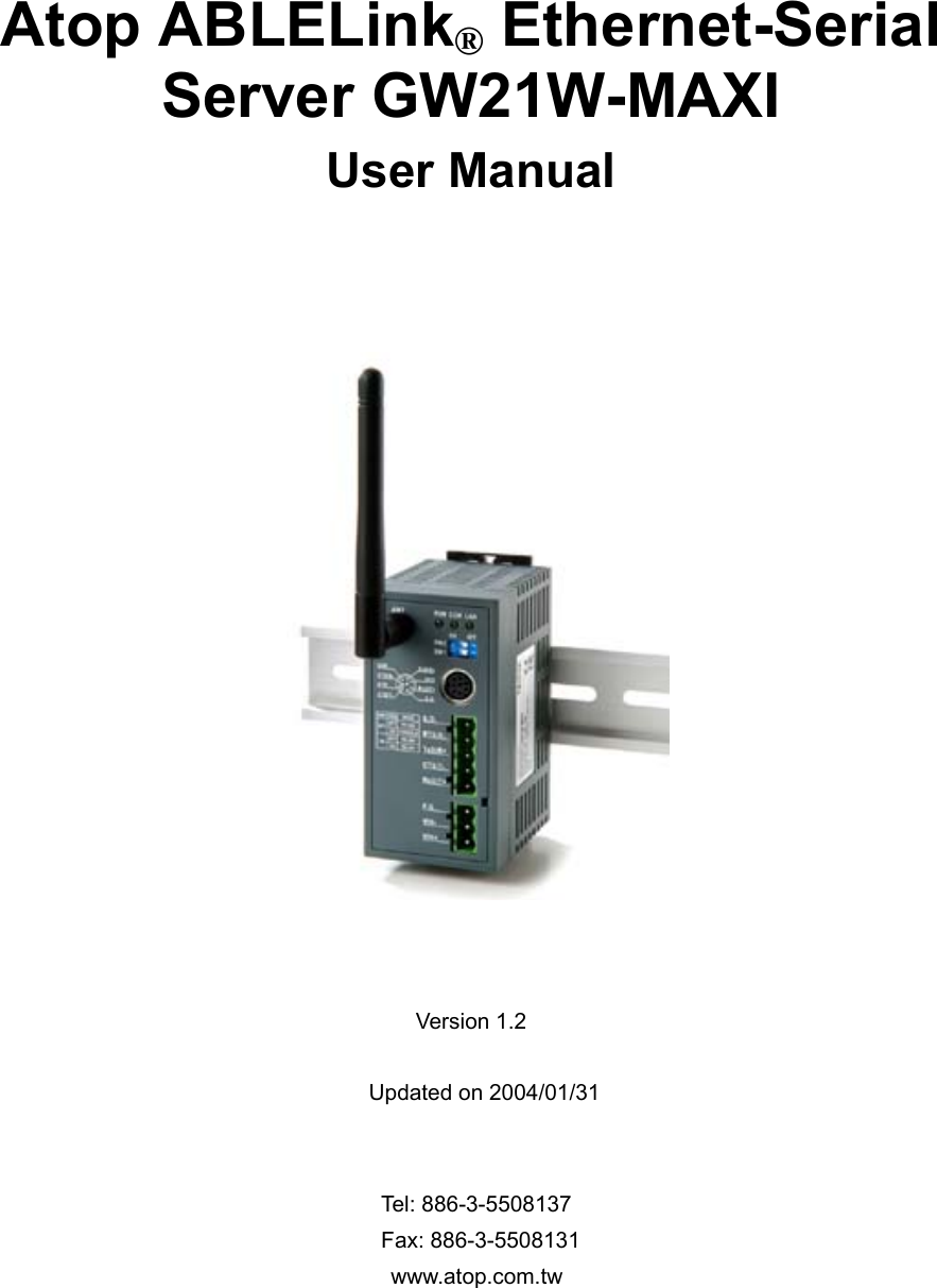
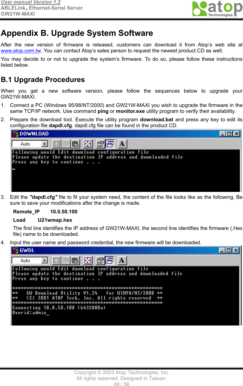
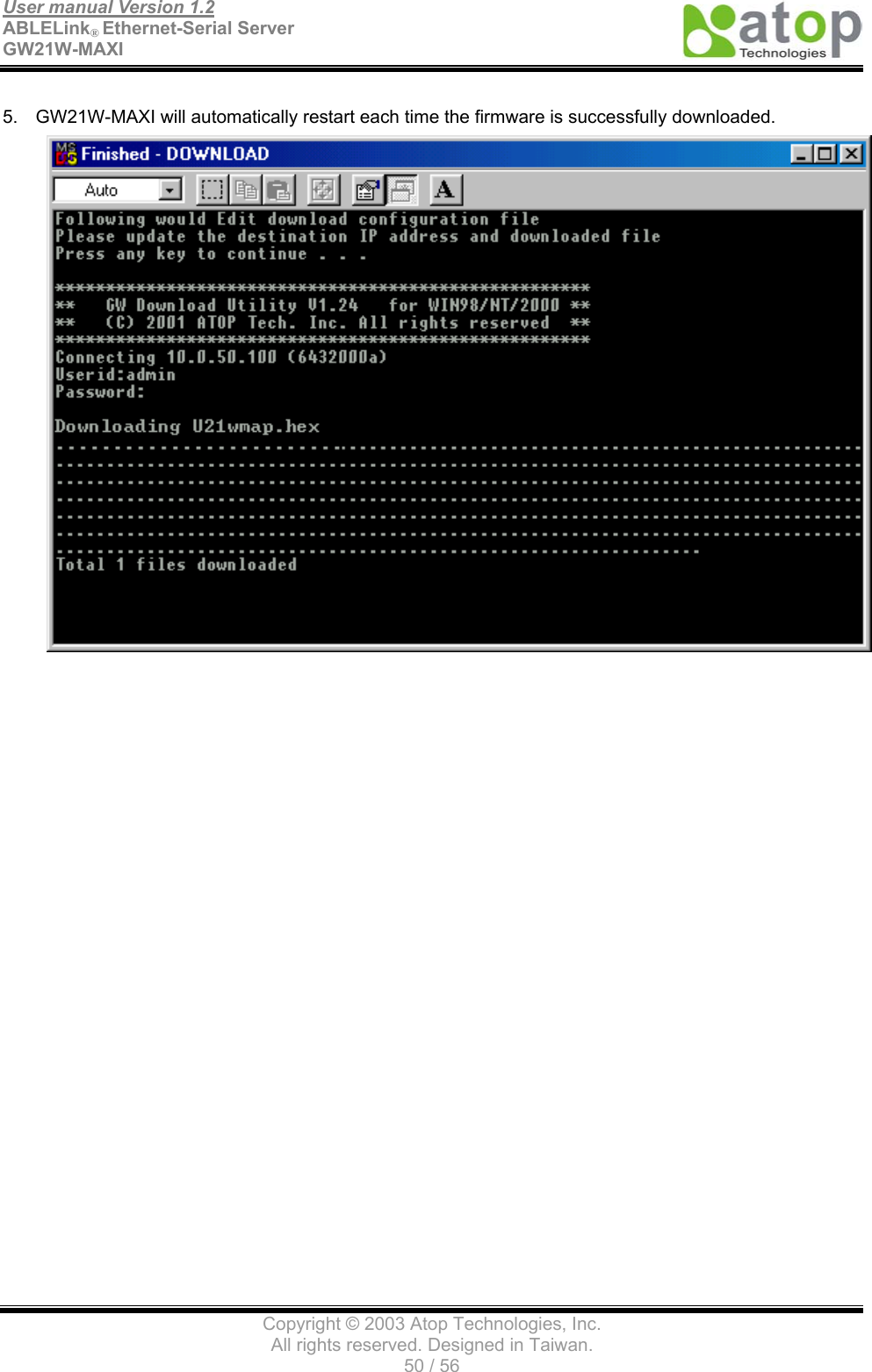
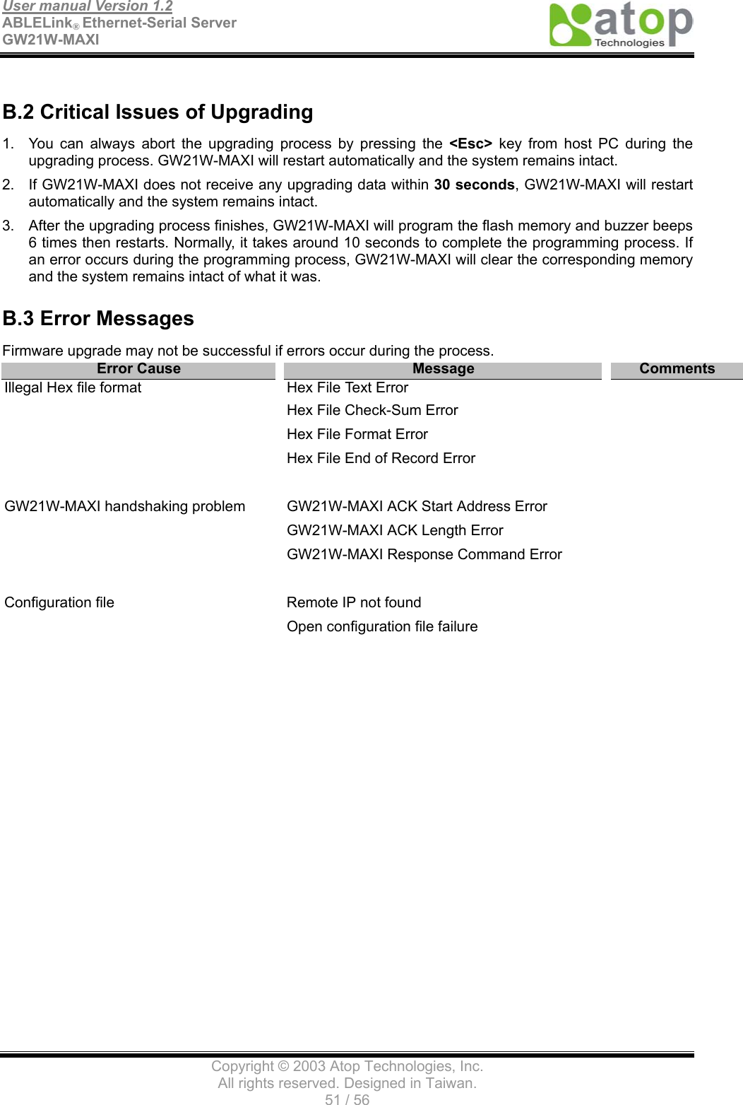
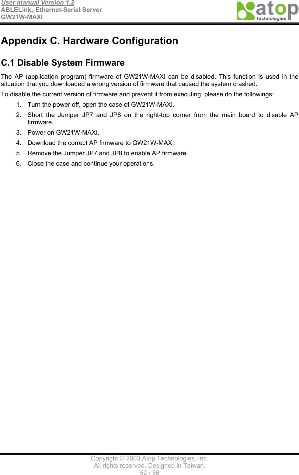
ATOP Technologies GW21W-MAXI Wireless Serial Server User Manual
ATOP Technologies, INC. Wireless Serial Server
UserManual.wiki
>
ATOP Technologies
>
GW21W MAXI User Manual
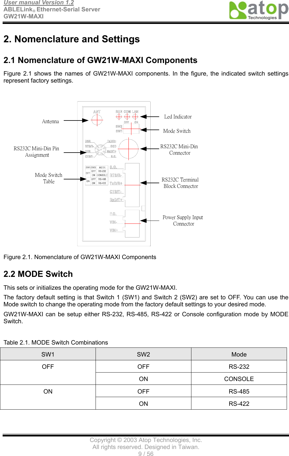
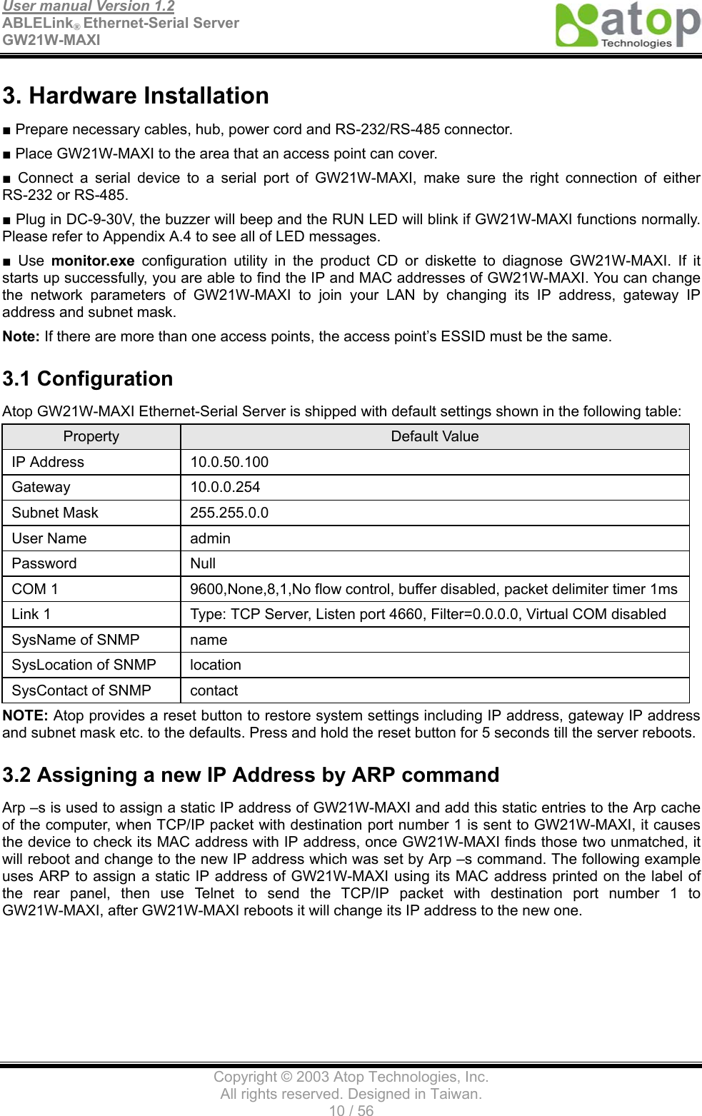
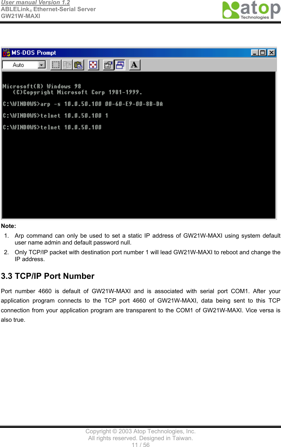
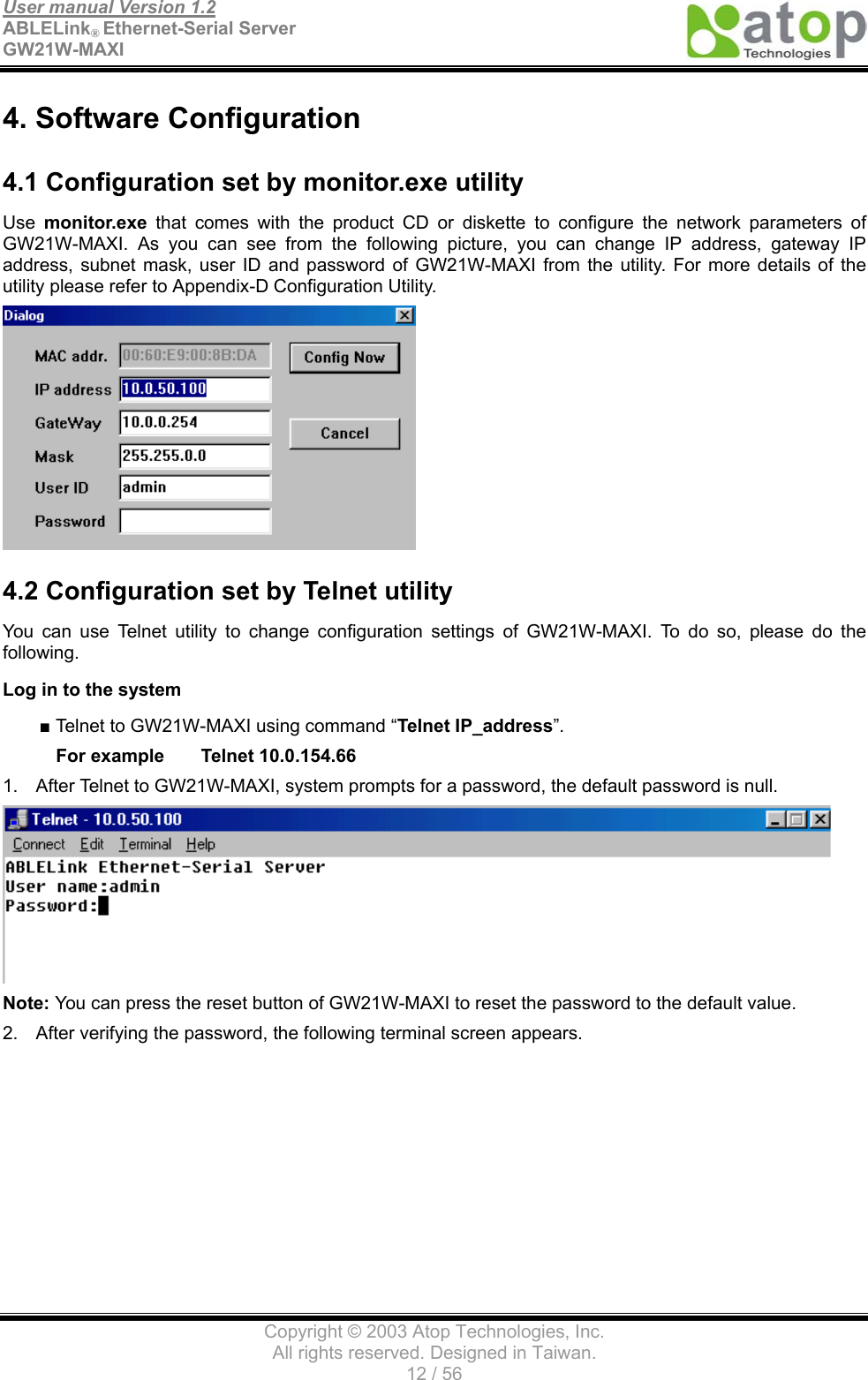
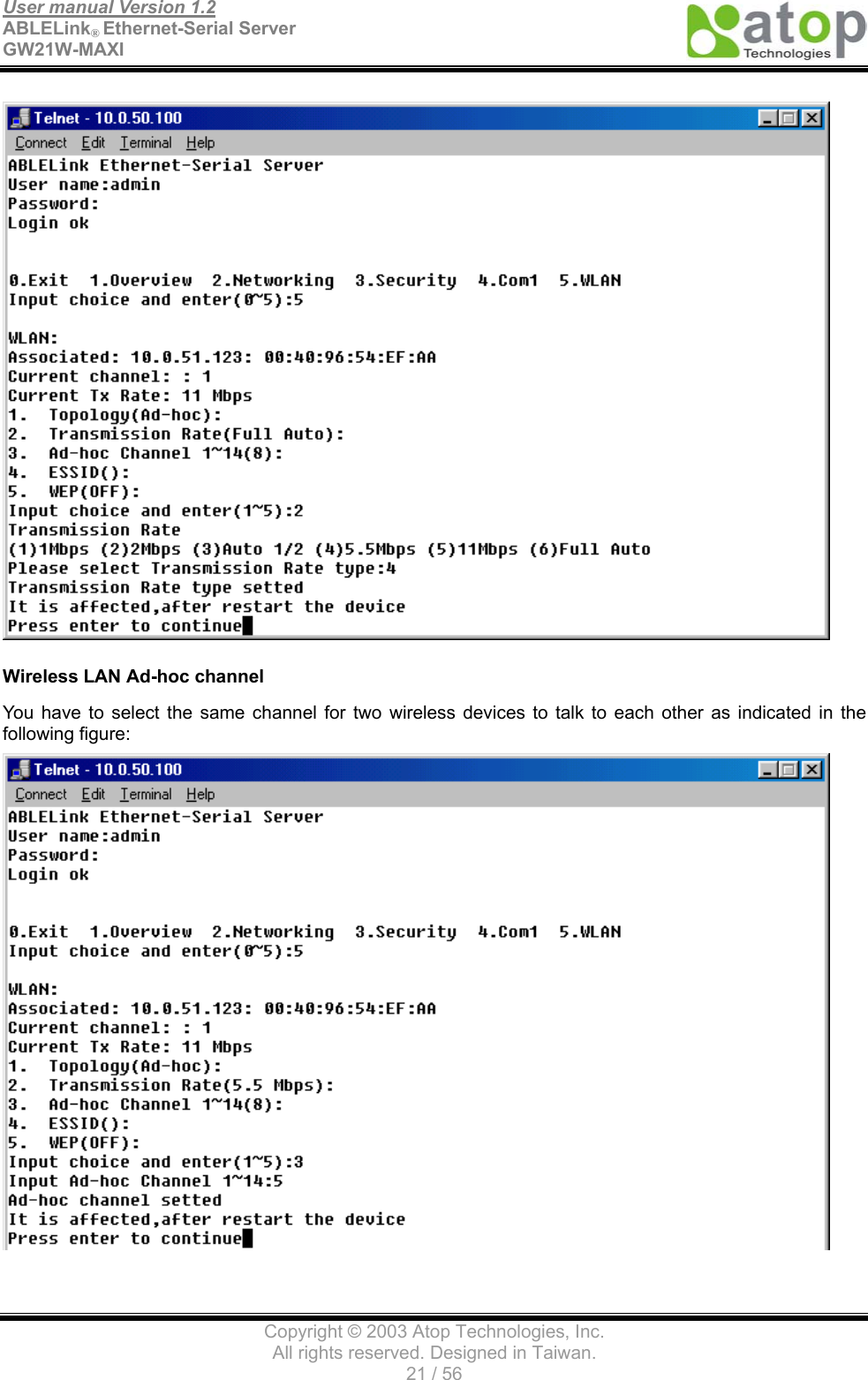
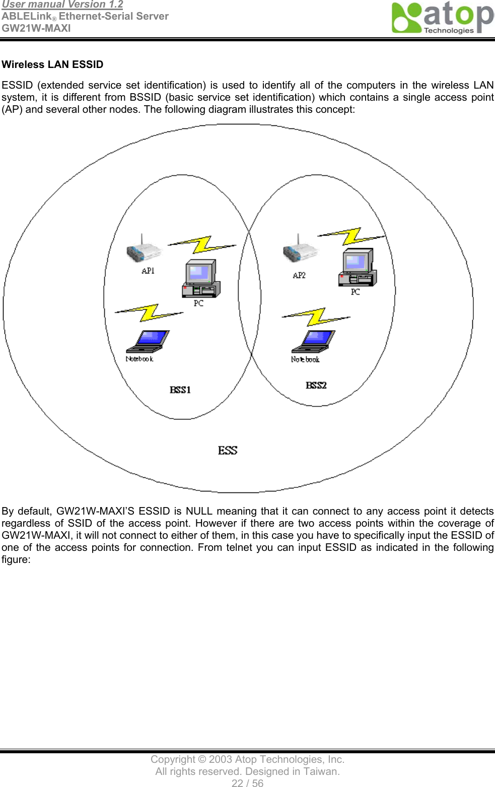
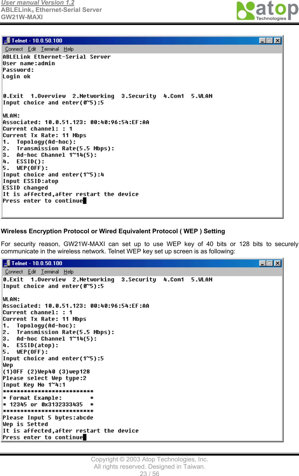
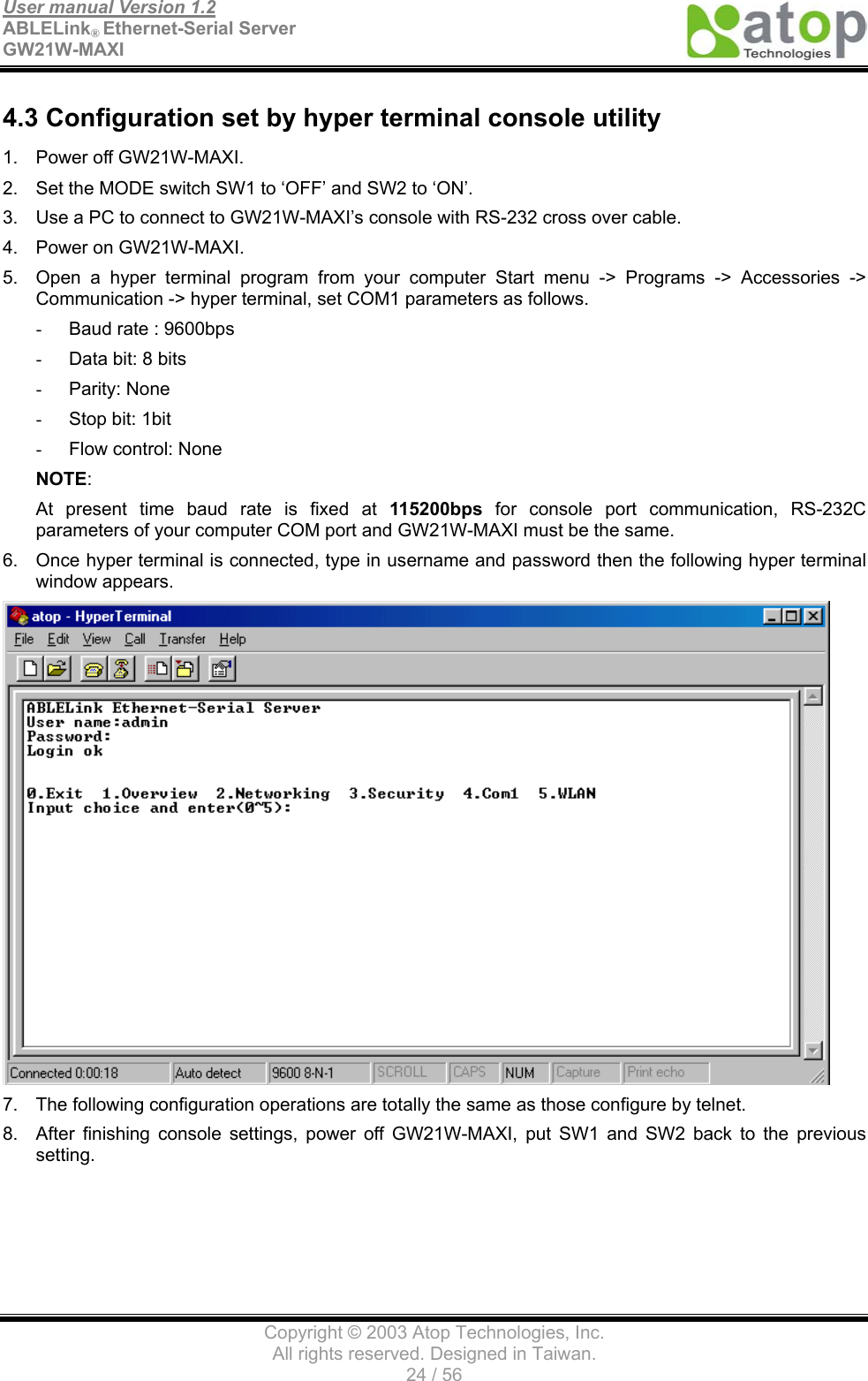
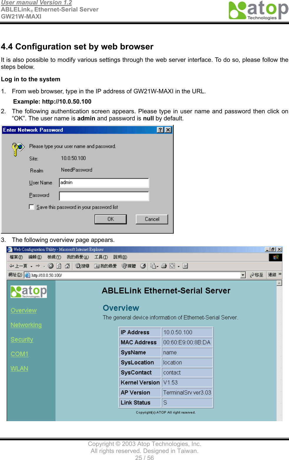
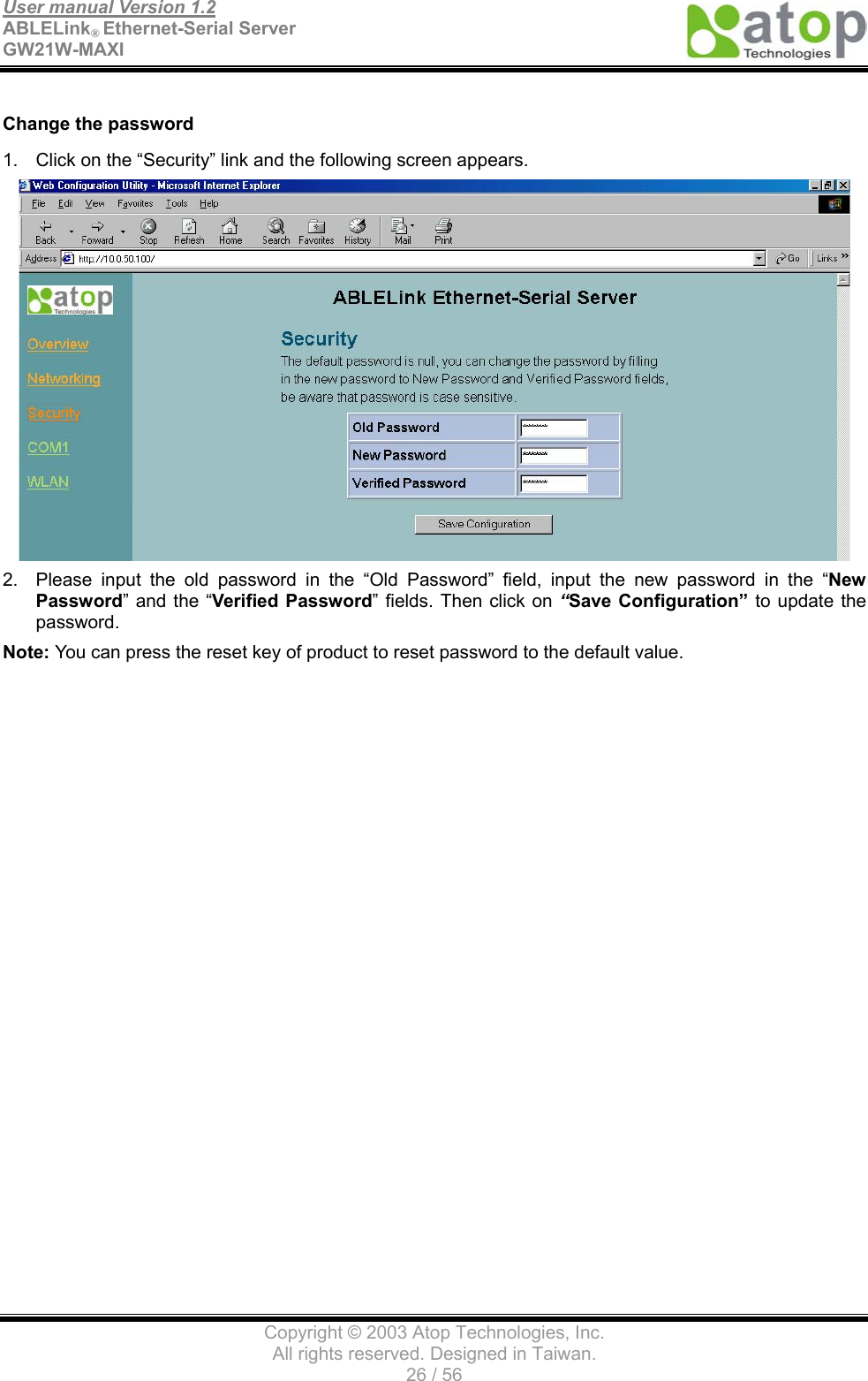
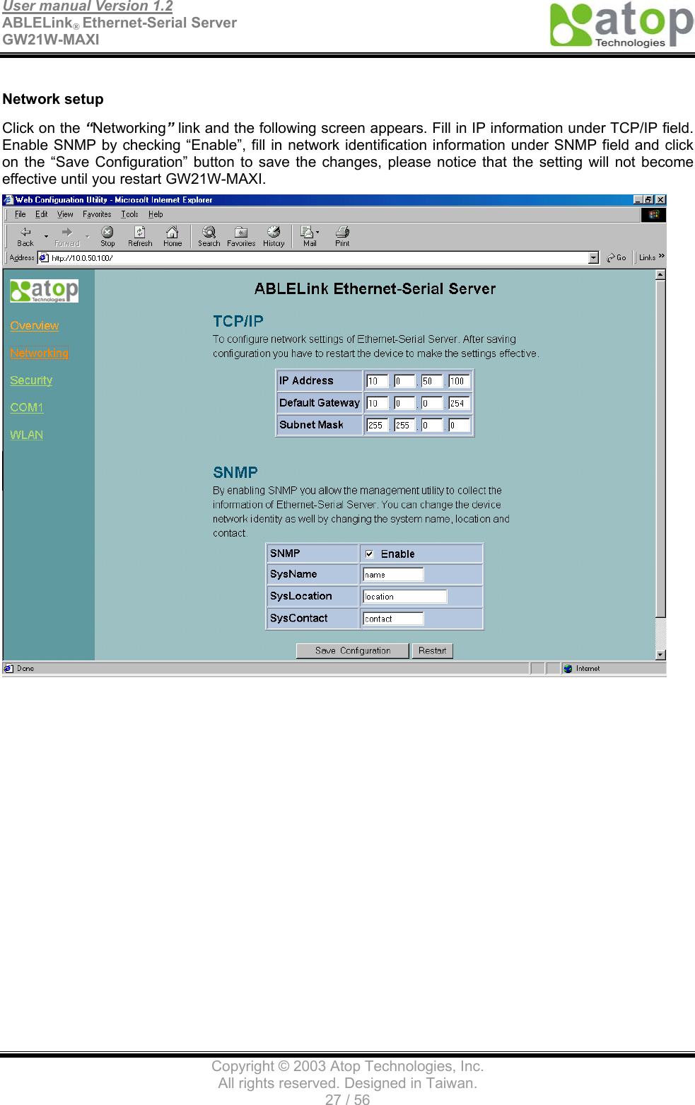
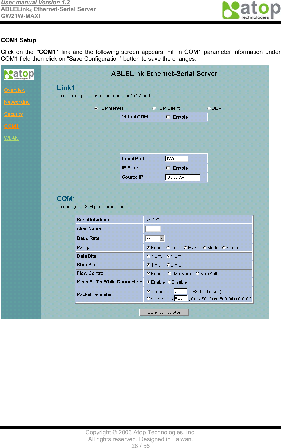
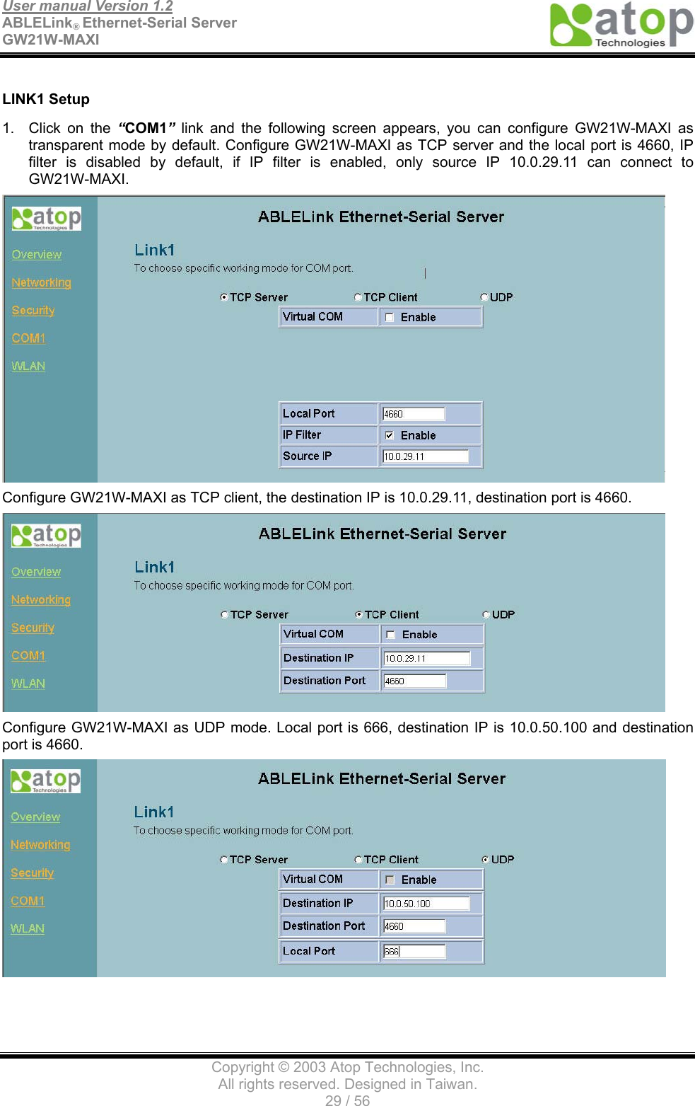
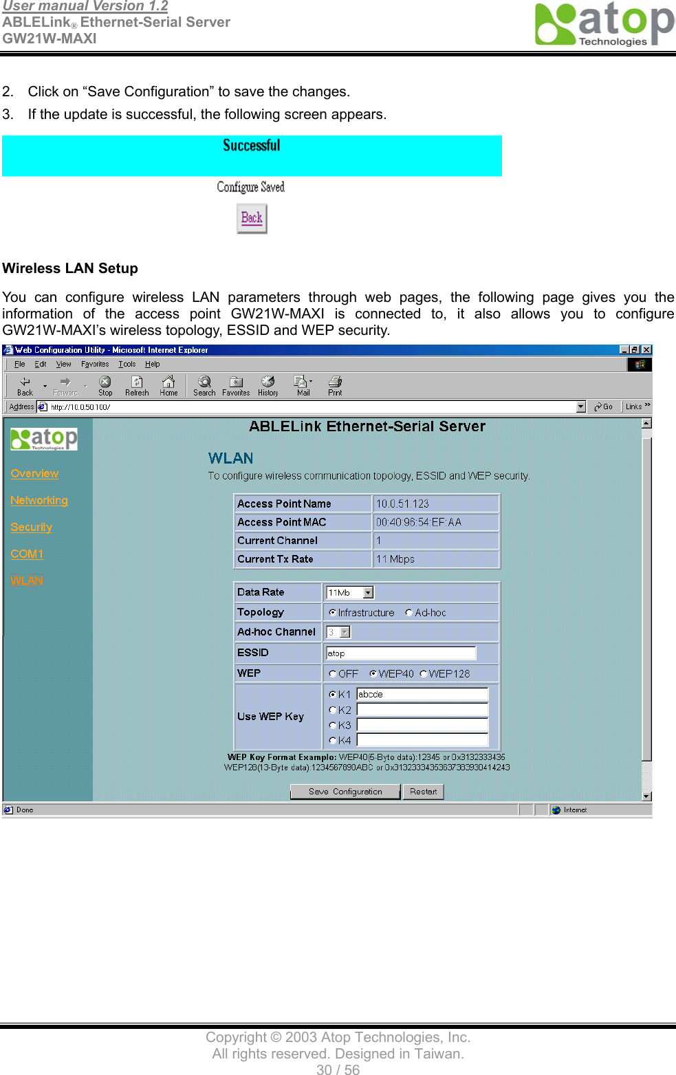
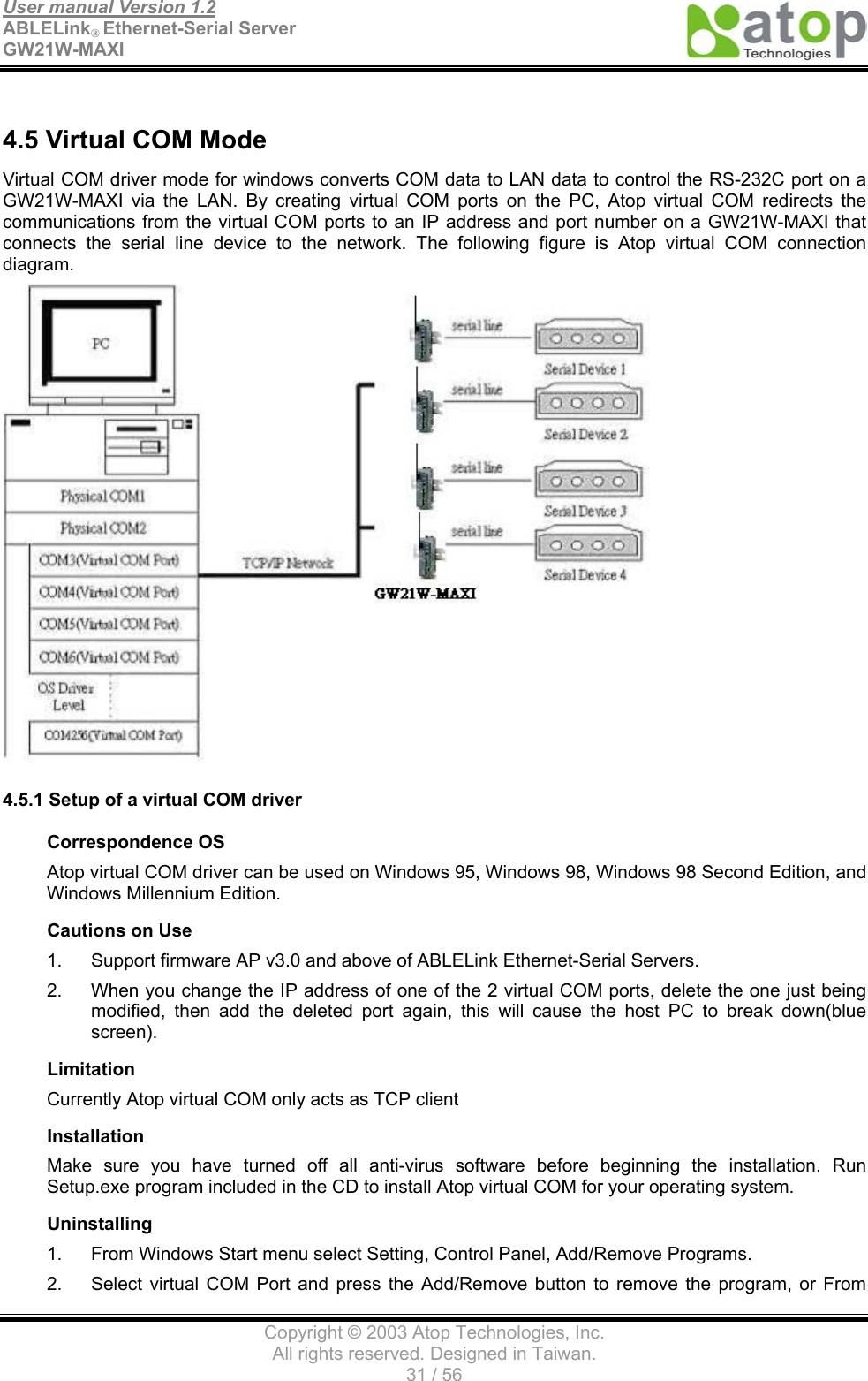
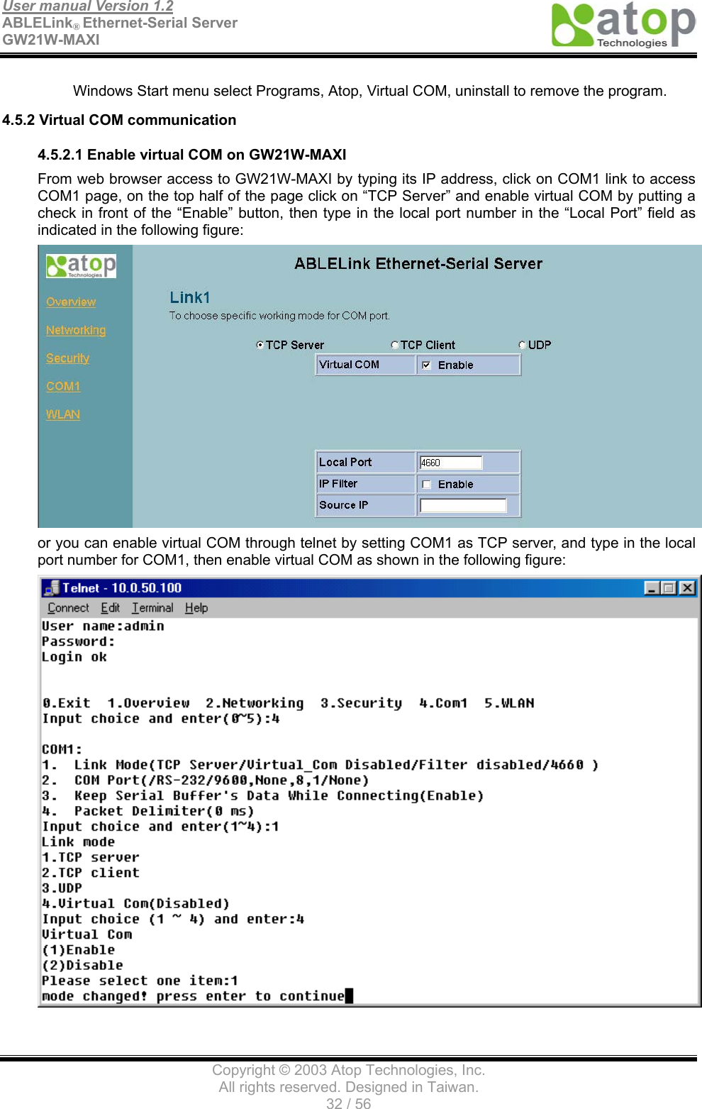
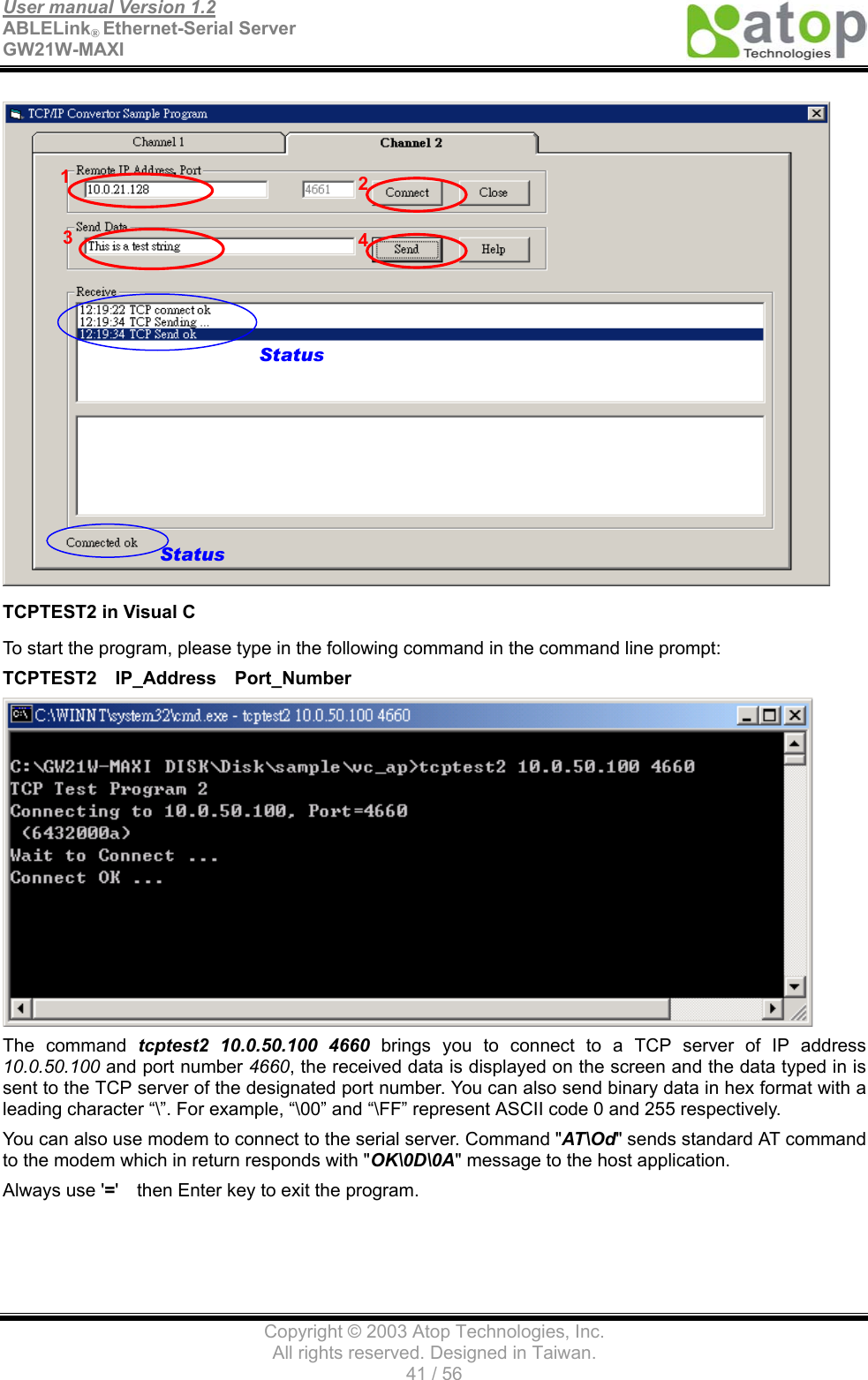
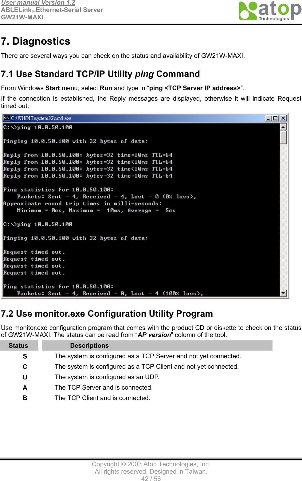
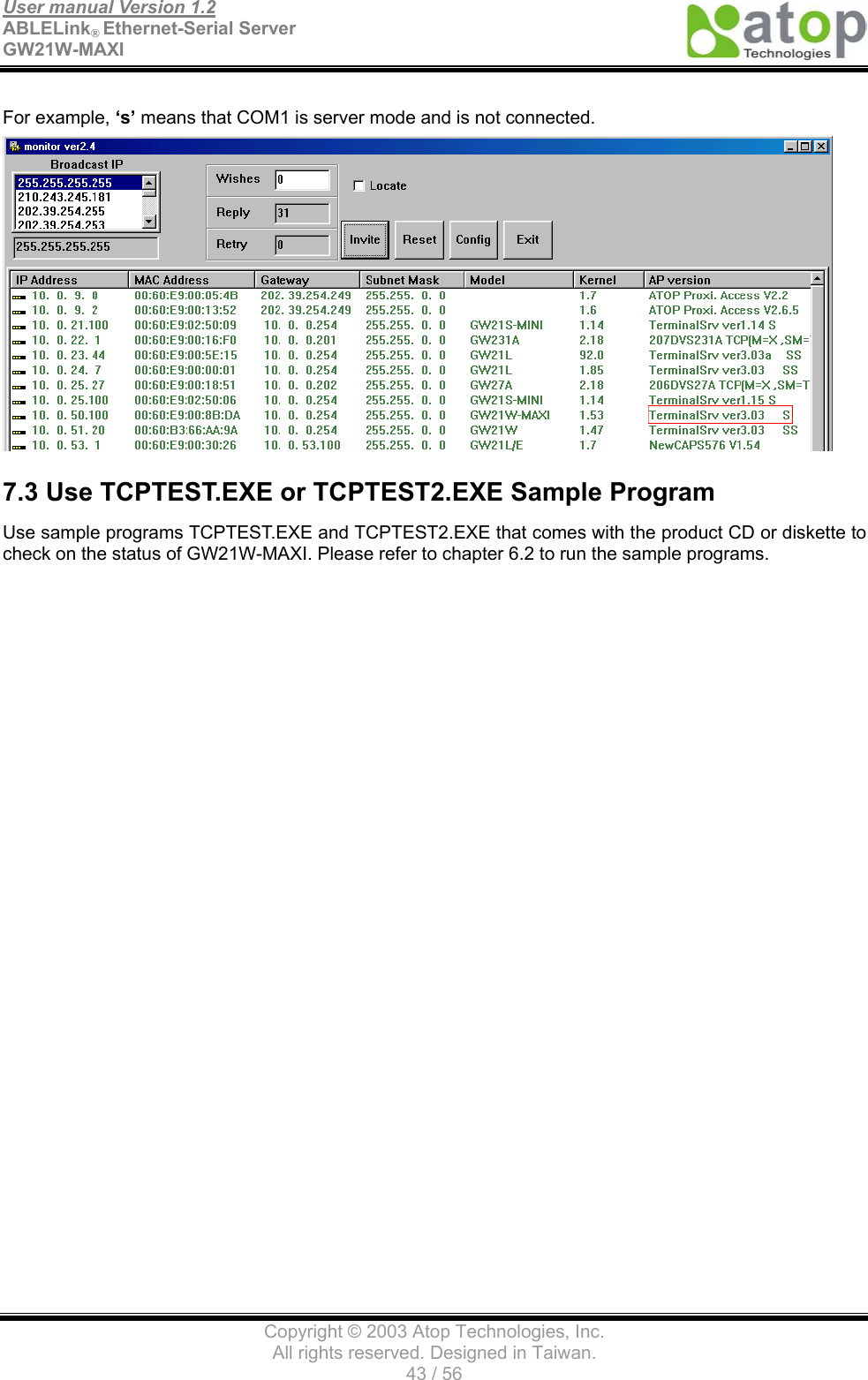
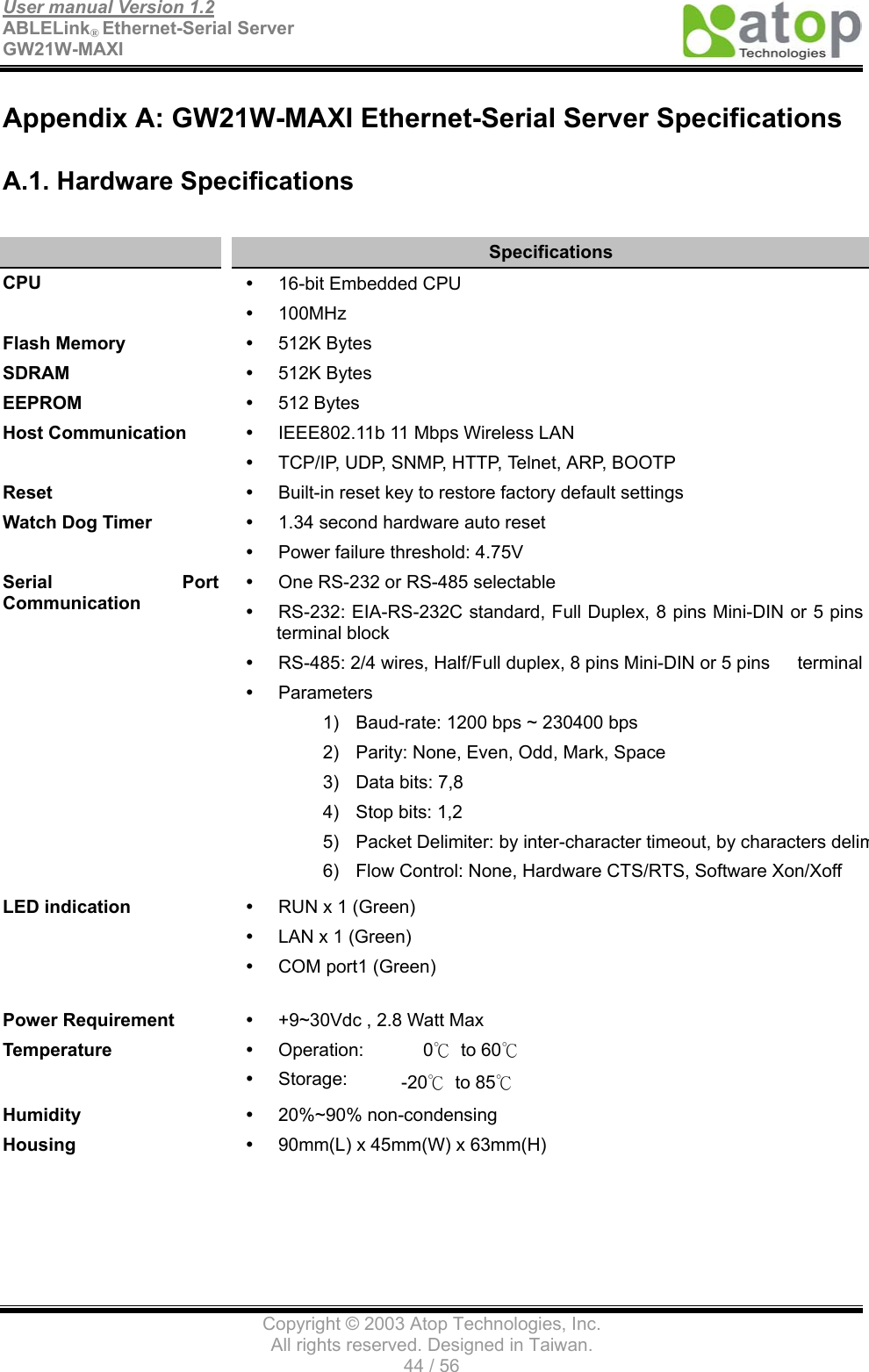
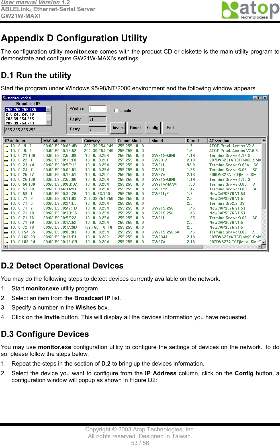
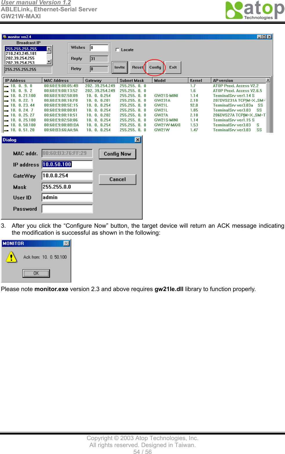
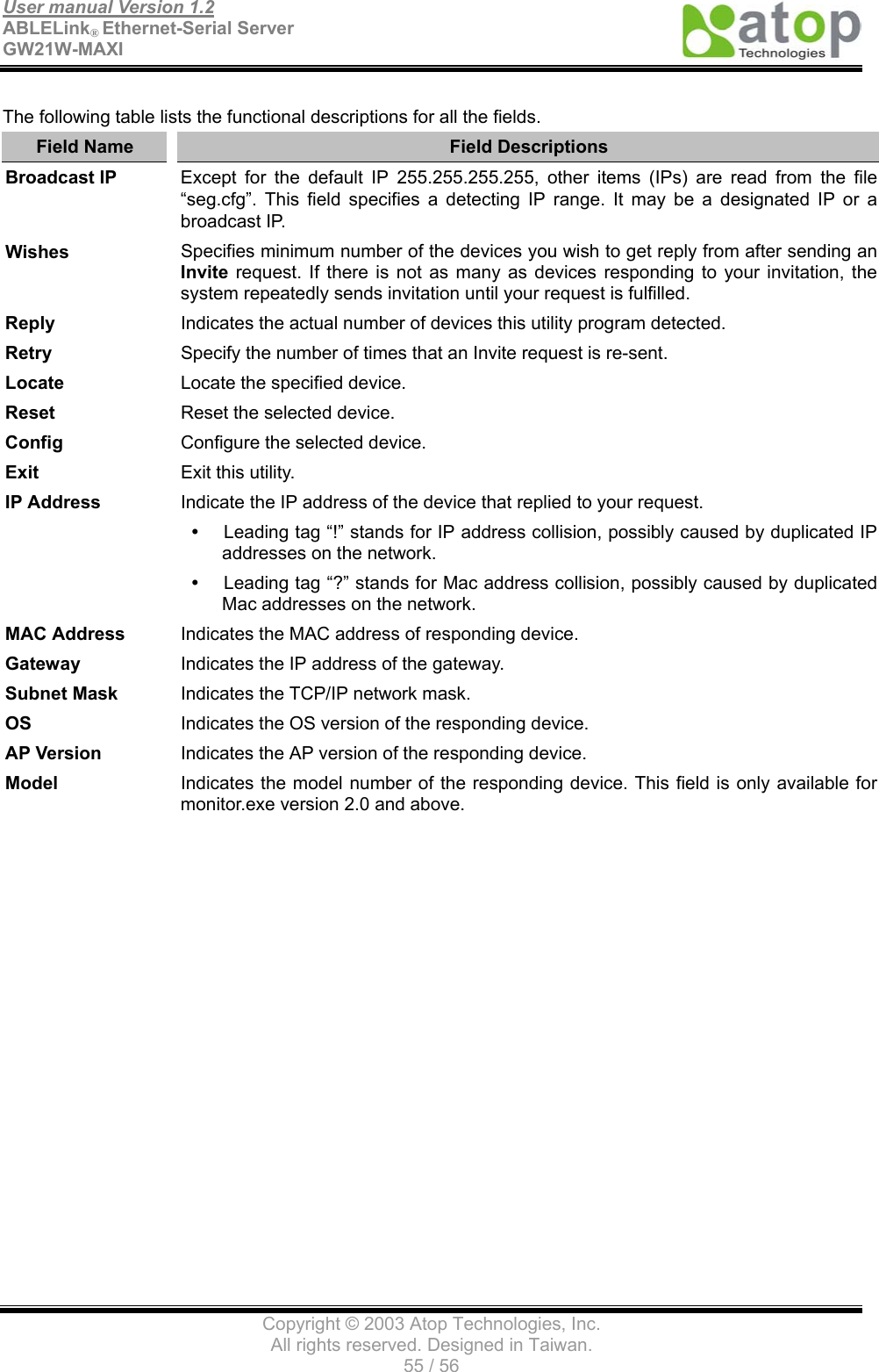
User Manual
Navigation menu
Upload a User Manual
Namespaces
Wiki Guide
HTML
PDF
Info
Views
User Manual
Discussion / Help
Navigation