ATOP Technologies SW2001-WGN1 Wireless Serial Server User Manual Manual
ATOP Technologies, INC. Wireless Serial Server Manual
Manual
Atop ABLELink® Wireless Serial
Server SW2001
User Manual
Version 1.0
Updated on 2006/06/06
Tel: 886-3-5508137
Fax: 886-3-5508131


User manual Version 1.0
ABLELink Wireless Serial Server
SW2001
Copyright © 2006 Atop Technologies, Inc.
All rights reserved. Designed in Taiwan.
2 / 51
IMPORTANT ANNOUNCEMENT
The information contained in this document is the property of Atop Technologies, Inc. and is supplied for
the sole purpose of the operation and maintenance of products of Atop Technologies, Inc. No part of this
publication is to be used for any other purposes, and it is not to be reproduced, copied, disclosed,
transmitted, stored in a retrieval system, or translated into any human or computer language, in any form,
by any means, in whole or in part, without the prior express written consent of Atop Technologies, Inc.
Published by
Atop Technologies, Inc.
2F, No. 146, Sec. 1, Tung-Hsing Rd.
Jubei City, Hsinchu 302
Taiwan, R.O.C.
Tel: 886-3-5508137
Fax: 886-3-5508131
www.atop.com.tw
Copyright © 2006 Atop Technologies, Inc. All rights reserved.
All other product names referenced herein are registered trademarks of their respective companies.

User manual Version 1.0
ABLELink Wireless Serial Server
SW2001
Copyright © 2006 Atop Technologies, Inc.
All rights reserved. Designed in Taiwan.
3 / 51
FCC WARNING
Class B for Wireless Serial Server (Model: SW2001)
This SW2001 has been tested and found to comply with the limits for a Class B digital device, pursuant
to Part 15 of the FCC Rules. These limits are designed to provide reasonable protection against
harmful interference in a residential installation. This equipment generates, uses and can radiate radio
frequency energy and, if not installed and used in accordance with the instructions, may cause harmful
interference to radio communications. However, there is no guarantee that interference will not occur in
a particular installation. If this equipment does cause harmful interference to radio or television
reception, which can be determined by turning the equipment off and on, the user is encouraged to try to
correct the interference by one of the following measures:
l Reorient or relocate the receiving antenna.
l Increase the separation between the equipment and receiver.
l Connect the equipment into an outlet on a circuit different from that to which the receiver is
connected.
l Consult the dealer or an experienced radio/TV technician for help.
This device complies with Part 15 of the FCC Rules. Operation is subject to the following two conditions:
(1) This device may not cause harmful interference, and (2) this device must accept any interference
received, including interference that may cause undesired operation.
FCC Caution: Any changes or modifications not expressly approved by the party responsible for
compliance could void the user's authority to operate this equipment.
IMPORTANT NOTE:
FCC Radiation Exposure Statement:
This SW2001 complies with FCC radiation exposure limits set forth for an uncontrolled environment. This
SW2001 should be installed and operated with minimum distance 20cm between the radiator & your body.
This transmitter must not be co-located or operating in conjunction with any other antenna or transmitter.
IEEE 802.11b/g operation of this product in the U.S.A. is firmware-limited to channels 1 through 11.

User manual Version 1.0
ABLELink Wireless Serial Server
SW2001
Copyright © 2006 Atop Technologies, Inc.
All rights reserved. Designed in Taiwan.
4 / 51
CONTENTS
1. INTRODUCTION..............................................................................5
1.1 PACKAGING.........................................................................................................................5
1. 2 APPLICATION CONNECTIVITY ...............................................................................................6
2. NOMENCLATURE AND SETTINGS................................................8
2.1 NOMENCLATURE OF SW2001 COMPONENTS ........................................................................8
2.2 MODE SWITCH...................................................................................................................8
3. HARDWARE INSTALLATION..........................................................9
3.1 CONFIGURATION .................................................................................................................9
3.2 ASSIGNING A NEW IP ADDRESS BY ARP COMMAND ................................................................9
3.3 AUTO IP............................................................................................................................10
3.4 TCP/IP PORT NUMBER......................................................................................................11
4. SOFTWARE CONFIGURATION.....................................................11
4.1 CONFIGURATION SET BY MONITOR.EXE UTILITY....................................................................11
4.2 CONFIGURATION SET BY TELNET UTILITY.............................................................................11
4.4 CONFIGURATION SET BY WEB BROWSER .............................................................................30
4.5 VIRTUAL COM MODE ........................................................................................................37
4.5.1 Setup of a Virtual COM driver.................................................................................37
4.5.2 Virtual COM communication...................................................................................38
5. SNMP SETUP................................................................................41
5.1 SNMP NETWORK MANAGEMENT PLATFORM.......................................................................41
APPENDIX A: SW2001 WIRELESS SERIAL SERVER
SPECIFICATIONS.............................................................................42
A.1. HARDWARE SPECIFICATIONS ............................................................................................42
A.2. SOFTWARE SPECIFICATIONS.............................................................................................43
A.3 CONNECTOR PIN ASSIGNMENTS ........................................................................................43
A.3.1 COM Port...............................................................................................................43
A.3.2 Power terminal block connector.............................................................................45
A.4 LED INDICATION FOR LINK STATUS.....................................................................................46
A.4.1 Detect SW2001 startup..........................................................................................46
A.4.2 Detect SW2001 Signal Strength.............................................................................46
APPENDIX B CONFIGURATION UTILITY.........................................48
D.1 RUN THE UTILITY...............................................................................................................48
D.2 DETECT OPERATIONAL DEVICES........................................................................................48
D.3 CONFIGURE DEVICES........................................................................................................48

User manual Version 1.0
ABLELink Wireless Serial Server
SW2001
Copyright © 2006 Atop Technologies, Inc.
All rights reserved. Designed in Taiwan.
5 / 51
1. Introduction
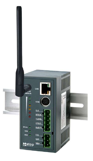
Atop SW2001 Wireless Serial Server is a gateway between Ethernet (TCP/IP) and RS-232/RS-485
communications. It allows almost any serial device to be connected to a new or existing wireless network.
The information transmitted by SW2001 is transparent to both host computers (IP network over wireless
LAN or Ethernet) and devices (RS-232/RS-485). Data coming from the wireless LAN or Ethernet (TCP/IP)
is sent to the designated RS-232/RS-485 port and data being received from RS-232/RS-485 port is sent
to the Wireless or Ethernet (TCP/IP) transparently.
In the computer integration manufacturing or industrial automation area, Atop SW2001 Wireless Serial
Server is used for field devices to direct connect to Ethernet network. Terminal Server (main control
program run in SW2001) transforms whatever data received from RS-232/RS-485 to TCP/UDP port then
connects devices to the IP network via a single application program or multiple application programs.
Many control devices provide the ability to communicate with hosts through RS-232/RS-485 however
RS-232/RS-485 serial communication has its limitations. For one, it is hard to transfer data through a long
distance. With Atop SW2001, it is possible to communicate with a remote device in the Intranet
environment or even in the Internet and thus, increases the communication distance dramatically.
Flexible configuration options enable this unit to be setup remotely over IP network by Telnet, web browser,
or Window utility. Packed in a rugged DIN Rail mountable case and 9~30V DC power input range,
SW2001 is ideal for almost any industrial and manufacturing automation.
1.1 Packaging
Atop S2001 Wireless Serial Server x 1
Mini DIN to RS-232 DB 9 connector cable x 1
Wall mount x 2
Atop Wireless Serial Server quick start guide x 1
Product CD containing configuration utility and other tools
User manual Version 1.0
ABLELink Wireless Serial Server
SW2001
Copyright © 2006 Atop Technologies, Inc.
All rights reserved. Designed in Taiwan.
6 / 51
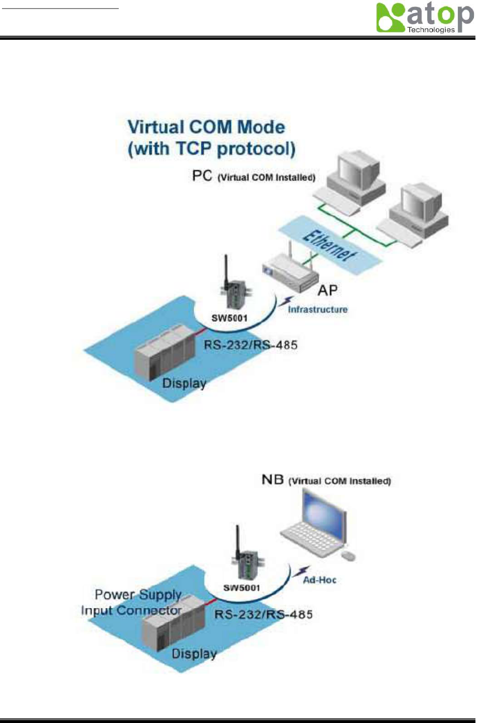
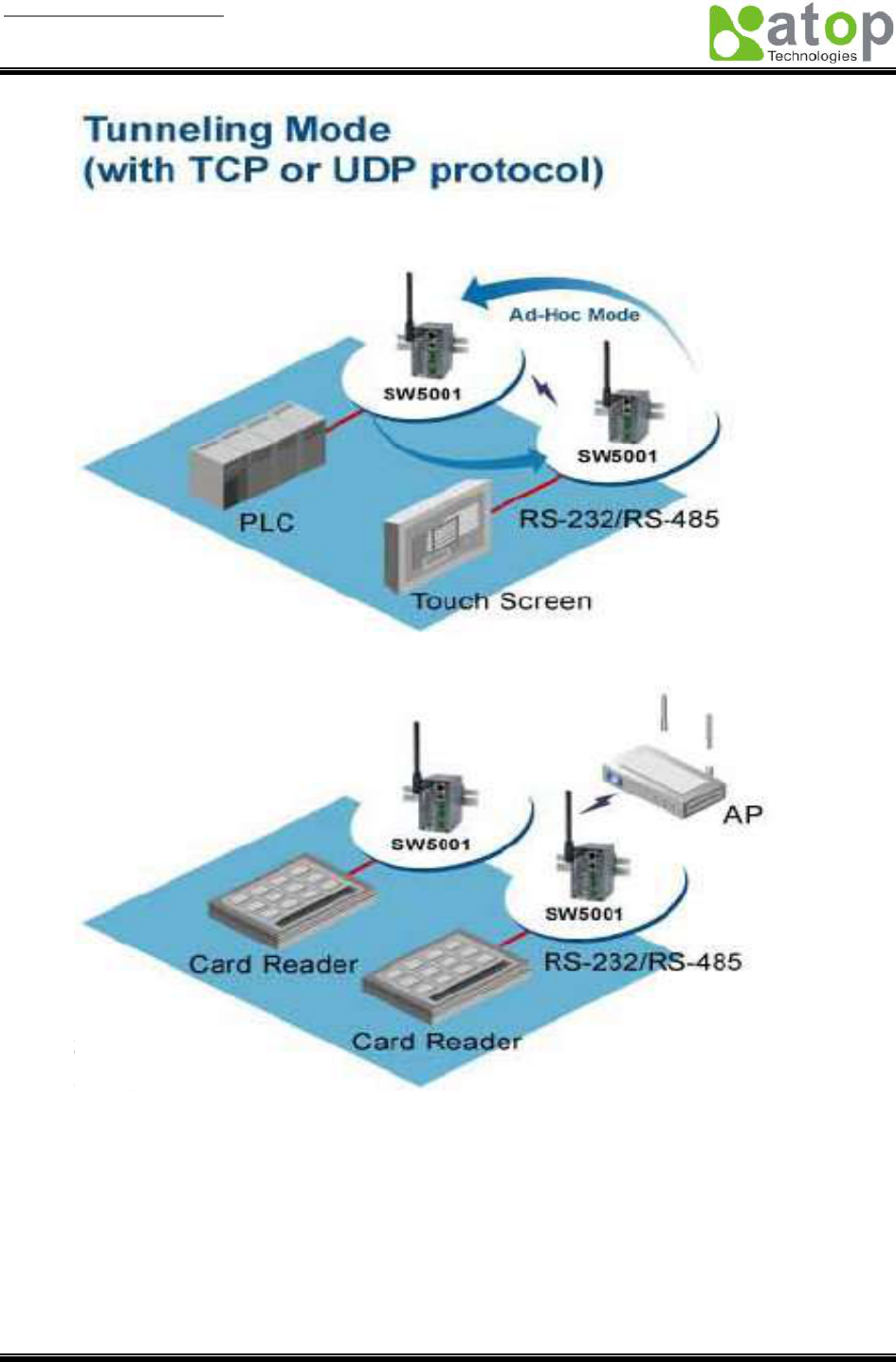
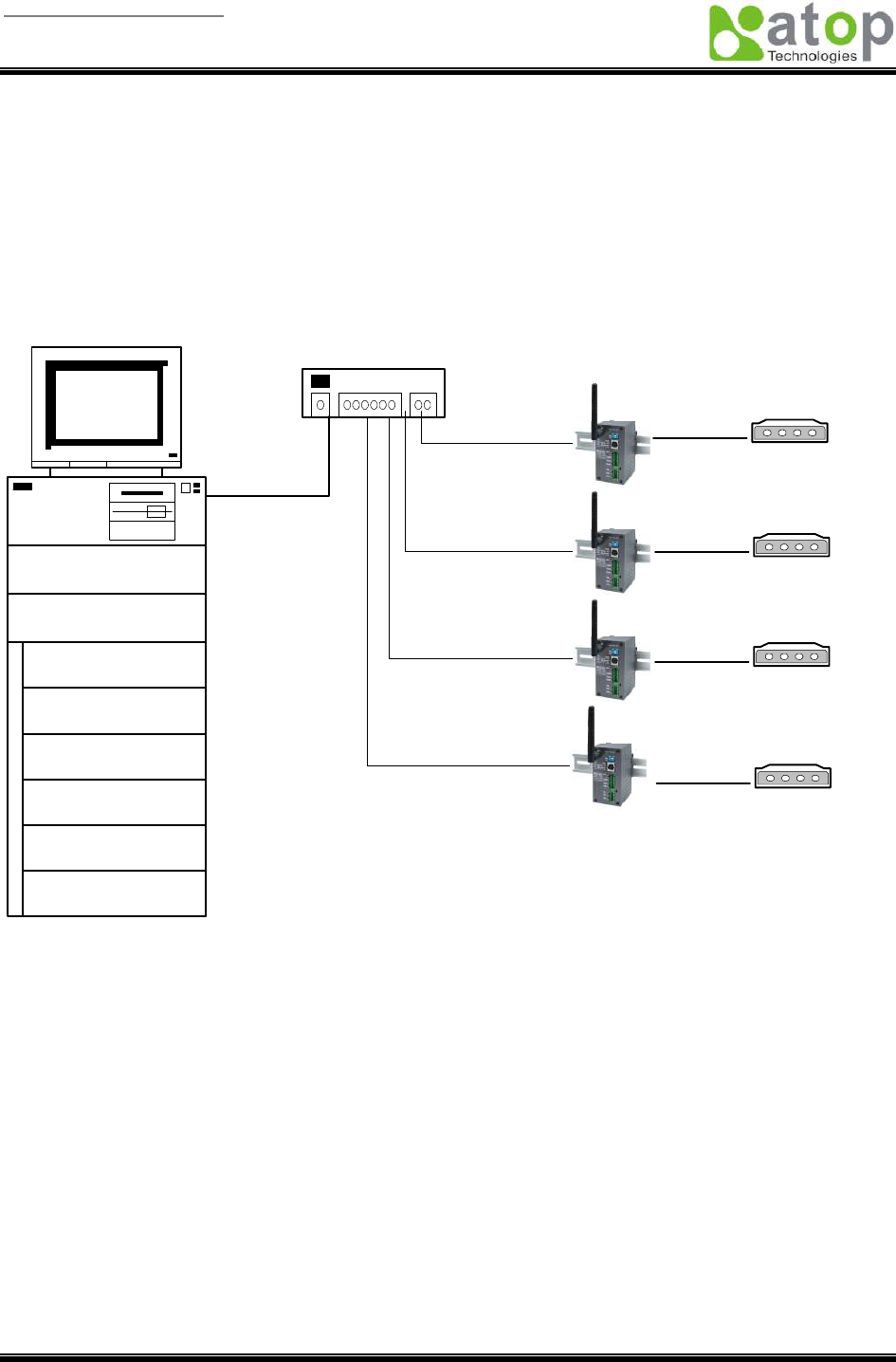
1. 2 Application Connectivity
User manual Version 1.0
ABLELink Wireless Serial Server
SW2001
Copyright © 2006 Atop Technologies, Inc.
All rights reserved. Designed in Taiwan.
7 / 51
User manual Version 1.0
ABLELink Wireless Serial Server
SW2001
Copyright © 2006 Atop Technologies, Inc.
All rights reserved. Designed in Taiwan.
8 / 51
2. Nomenclature and Settings
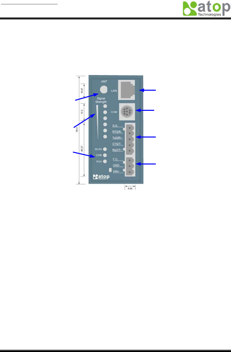
2.1 Nomenclature of SW2001 Components
Figure 2.1 shows the names of SW2001 components. In the figure, the indicated switch settings represent
factory settings.
10/100M
Ethernet port for
settings
Mini-DIN Connector
for Serial port
5-pin Terminal
Block for Serial
port
3-pin Terminal
Block for Power
input
SMA rev. Antenna
Connector
LED indication
for Wireless
Status
LED indication
for System
Status
Figure 2.1. Nomenclature of SW2001 Components
2.2 MODE Switch
This sets or initializes the operating mode for the SW2001.
The factory default setting is RS-232 mode. You can use the software configurations to change the
operating mode from the factory default settings to your desired mode by web or telnet tools.
SW2001 can be setup either RS-232, RS-485 or RS-422 mode by remote network tools, ex. Web browser
and telnet.

User manual Version 1.0
ABLELink Wireless Serial Server
SW2001
Copyright © 2006 Atop Technologies, Inc.
All rights reserved. Designed in Taiwan.
9 / 51
3. Hardware Installation
§ Prepare necessary cables, hub, power cord and RS-232/RS-485 connector.
§ Place SW2001 to the area that an access point can cover, or connector it via Ethernet cable with RJ45
connecor.
§ Connect a serial device to a serial port of SW2001, make sure the right connection of either RS-232 or
RS-485.
§ Plug in DC-9-30V, the buzzer will beep and the RUN LED will blink if SW2001 functions normally.
Please refer to Appendix A.5 to see all of LED messages.
§ Use monitor.exe configuration utility in the product CD or diskette to diagnose SW2001. If it starts up
successfully, you are able to find the IP and MAC addresses of SW2001. You can change the network
parameters of SW2001 to join your LAN by changing its IP address, gateway IP address and subnet
mask.
Note: If there are more than one access points, the access point’s ESSID must be the same.
3.1 Configuration
Atop SW2001 Wireless Serial Server is shipped with default settings shown in the following table:
Property Default Value
IP Address 10.0.50.100
Gateway 10.0.0.254
Subnet Mask 255.255.0.0
User Name admin
Password Null
COM 1 9600,None, 8, 1, No flow control, buffer disabled, packet delimiter timer 1ms
Link 1 Type: TCP Server, Listen port 4660, Filter=0.0.0.0, Virtual COM disabled
SysName of SNMP name
SysLocation of SNMP location
SysContact of SNMP contact
NOTE: Atop provides a default button to restore system settings including IP address, gateway IP address
and subnet mask etc. to the defaults. Press and hold the default button for 5 seconds till the server
reboots.
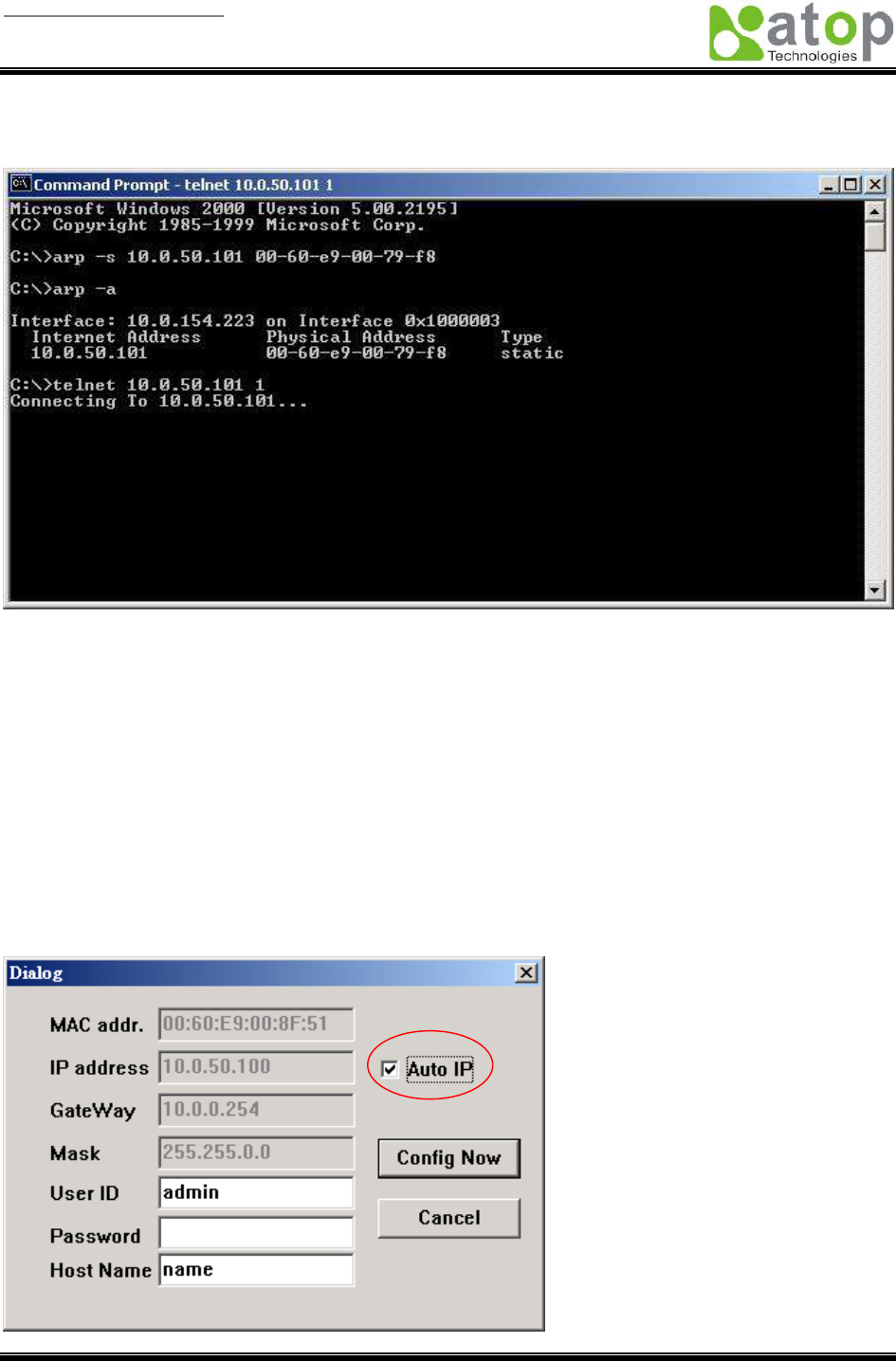
3.2 Assigning a new IP Address by ARP command
arp –s is used to assign a static IP address of SW2001 and add this static entries to the ARP cache of the
computer, when TCP/IP packet with destination port number 1 is sent to SW2001, it causes the device to
check its MAC address with IP address, once SW2001 finds those two unmatched, it will reboot and
change to the new IP address which was set by arp –s command. The following example uses ARP to
assign a static IP address of SW2001 using its MAC address printed on the label of the rear panel, then
User manual Version 1.0
ABLELink Wireless Serial Server
SW2001
Copyright © 2006 Atop Technologies, Inc.
All rights reserved. Designed in Taiwan.
10 / 51
use Telnet to send the TCP/IP packet with destination port number 1 to SW2001, after SW2001 reboots it
will change its IP address to the new one.
Note:
1. Arp command can only be used to set a static IP address of SW2001 using system reset user name
admin and default password null.
2. Only TCP/IP packet with destination port number 1 will lead SW2001 to reboot and change the IP
address.
3.3 Auto IP
A DHCP server automatically assigns the IP address and network settings. SW2001 supports DHCP.
It will supply for the unit with an IP address gateway address, and subnet mask. You may use
Monitor.exe software to search network information automatically by putting a check on Auto IP on
Dialog window.
User manual Version 1.0
ABLELink Wireless Serial Server
SW2001
Copyright © 2006 Atop Technologies, Inc.
All rights reserved. Designed in Taiwan.
11 / 51
3.4 TCP/IP Port Number
Port number 4660 is default of SW2001 and is associated with serial port COM1. After your application
program connects to the TCP port 4660 of SW2001, data being sent to this TCP connection from your
application program are transparent to the COM1 of SW2001. Vice versa is also true.
4. Software Configuration
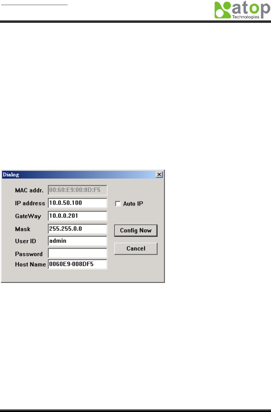
4.1 Configuration set by monitor.exe utility
Use monitor.exe that comes with the product CD or diskette to configure the network parameters of
SW2001. As you can see from the following picture, you can change IP address, gateway IP address,
subnet mask, user ID and password of SW2001 from the utility. For more details of the utility please refer
to Appendix-D Configuration Utility.
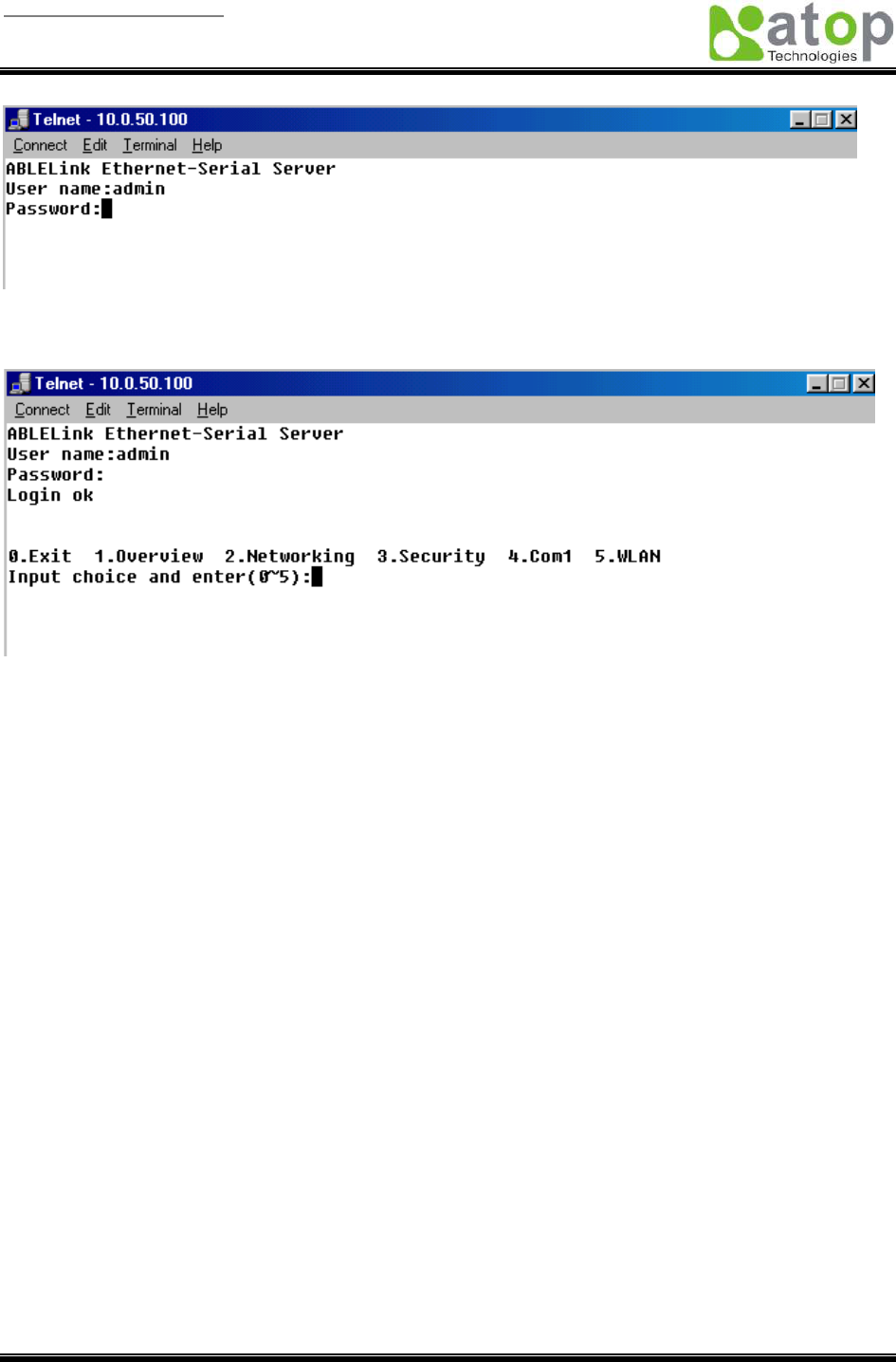
4.2 Configuration set by Telnet utility
You can use Telnet utility to change configuration settings of SW2001. To do so, please do the following.
Log in to the system
§ Telnet to SW2001 using command “Telnet IP_address”.
For example Telnet 10.0.50.100
1. After Telnet to SW2001, system prompts for a password, the default password is null.
User manual Version 1.0
ABLELink Wireless Serial Server
SW2001
Copyright © 2006 Atop Technologies, Inc.
All rights reserved. Designed in Taiwan.
12 / 51
Note: You can press the default button of SW2001 to reset the password to the default value.
2. After verifying the password, the following terminal screen appears.
Notes:
1. If SW2001 does not receive any command within 1 minute, Telnet will be terminated automatically.
2. The changes of networking parameters will take effect only when you exit and restart SW2001.
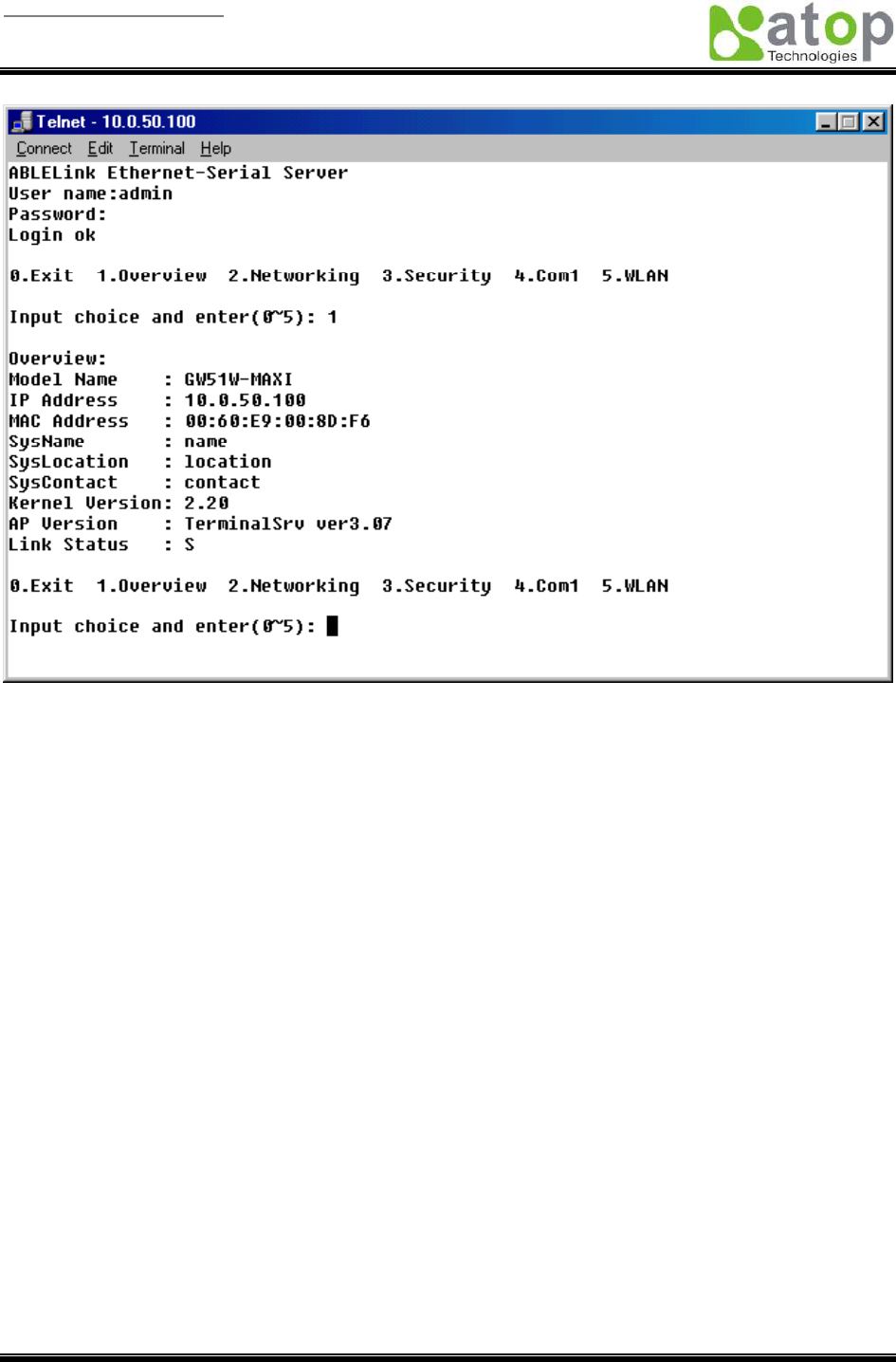
3. Select “1” from “Input choice and enter (0~5):” to enter overview page as following:
User manual Version 1.0
ABLELink Wireless Serial Server
SW2001
Copyright © 2006 Atop Technologies, Inc.
All rights reserved. Designed in Taiwan.
13 / 51
This page gives you the general information of SW2001 including IP and MAC address, SNMP
information, kernel and AP version, and connection status of the device.
User manual Version 1.0
ABLELink Wireless Serial Server
SW2001
Copyright © 2006 Atop Technologies, Inc.
All rights reserved. Designed in Taiwan.
14 / 51
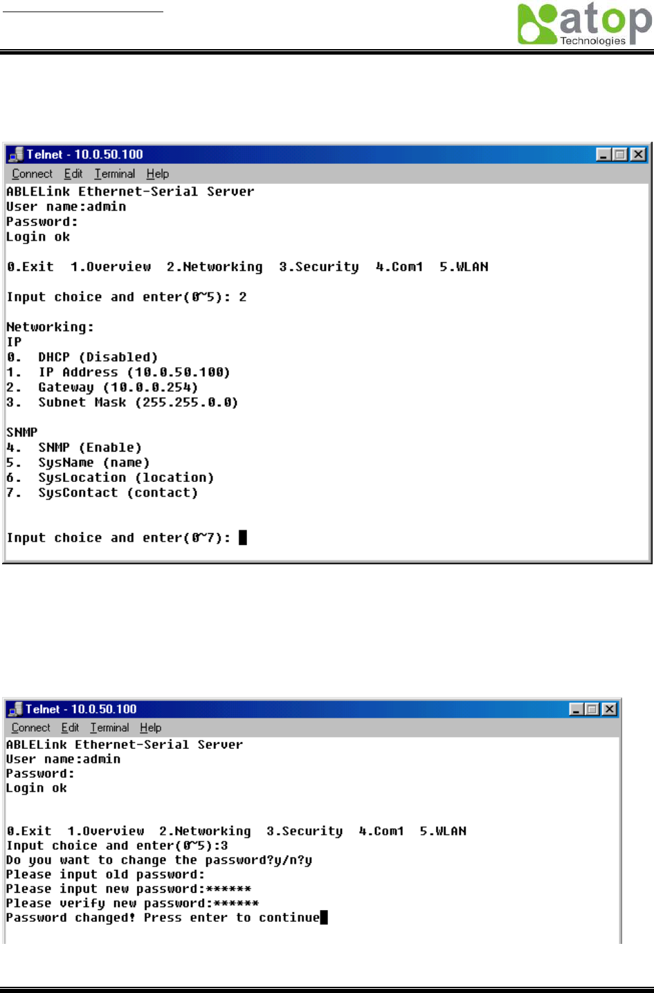
Networking
Select “2” from “Input choice and enter (0~5):” to enter Networking page as following:
This page allows you to change network settings of the device including IP address, subnet mask,
gateway IP address and SNMP information of SW2001. Please notice that any setting change made on
this page won’t take effect until you restart the device.
Change the password
1. Select “3” from “Input choice and enter (0~5):” the following screen appears.
2. If you want to change the password, please type the old password in the “Please input old password”
User manual Version 1.0
ABLELink Wireless Serial Server
SW2001
Copyright © 2006 Atop Technologies, Inc.
All rights reserved. Designed in Taiwan.
15 / 51
field, type the new password in the “Please input new password” and the “Please verify new
password” fields.
Note: You can press the default key of product to reset password to the default value.
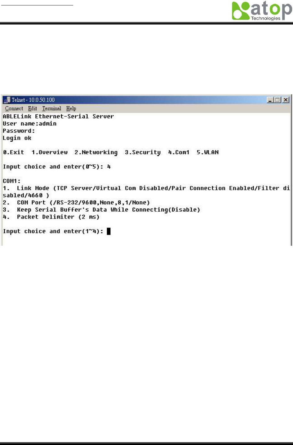
COM1 Setup
Select “4” from “Input choice and enter (0~5):” the following screen appears
The page gives you an opportunity to configure parameters of COM1 setting which includes COM1
working mode, port parameters, enabling or disabling serial buffer’s data and setting packet delimiter.
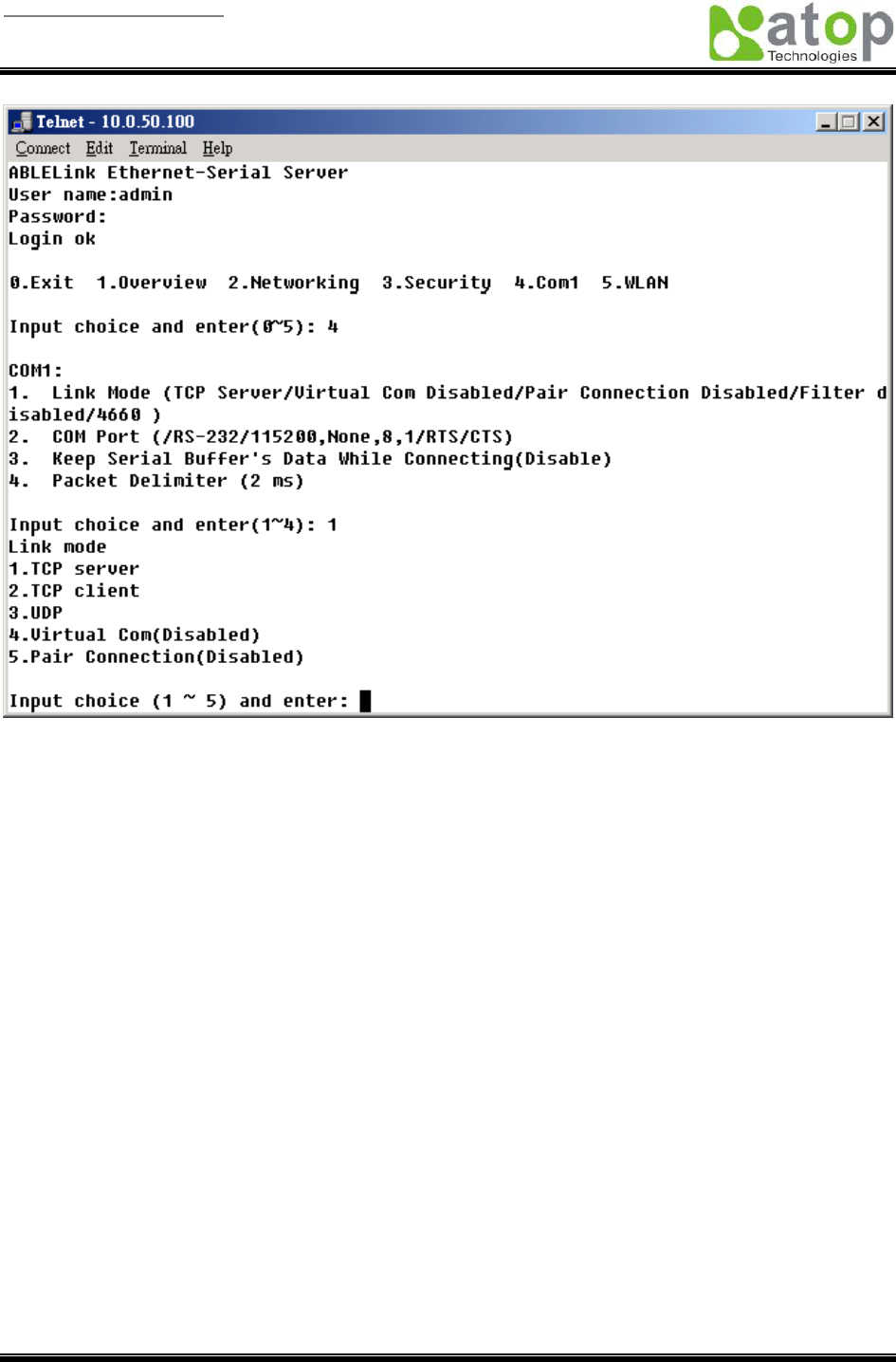
LINK1 Setup
Type 1 from “Input choice and enter (1~4):” of COM1, the following screen appears. Configure SW2001 as
TCP server and the local port is 4660. IP filter is disabled by default, if IP filter is enabled, only source IP
10.0.0.154 can connect to SW2001.
Note: IP filtering function is disabled if setting FILTER_IP to “0.0.0.0”.
User manual Version 1.0
ABLELink Wireless Serial Server
SW2001
Copyright © 2006 Atop Technologies, Inc.
All rights reserved. Designed in Taiwan.
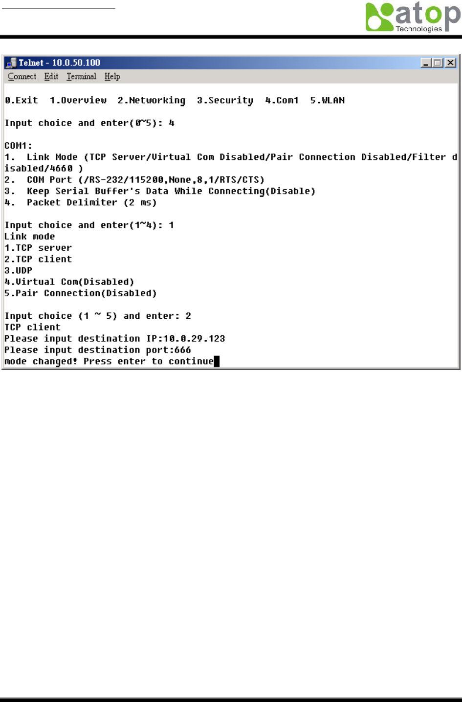
16 / 51
Configure SW2001 as TCP client, the destination IP is 10.0.29.123, destination port is 666.
User manual Version 1.0
ABLELink Wireless Serial Server
SW2001
Copyright © 2006 Atop Technologies, Inc.
All rights reserved. Designed in Taiwan.
17 / 51
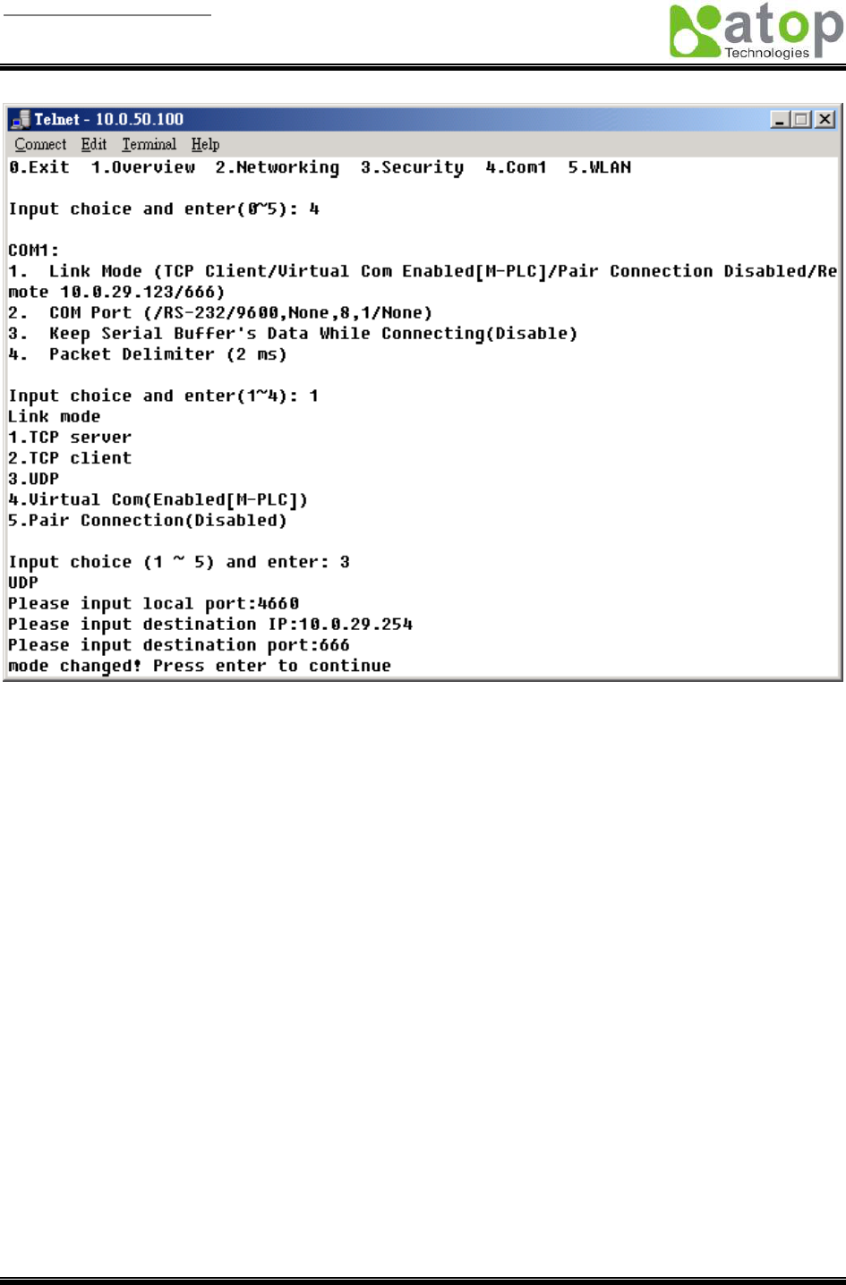
Configure SW2001 as UDP client, the local port is 4660, the destination IP is 10.0.29.254, destination port
is 666.
User manual Version 1.0
ABLELink Wireless Serial Server
SW2001
Copyright © 2006 Atop Technologies, Inc.
All rights reserved. Designed in Taiwan.
18 / 51
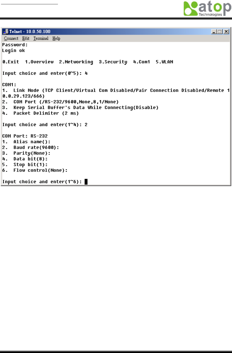
COM port setting
Type 2 from “Input choice and enter (1~4):” of COM1, the following screen appears, you can then give the
COM port alias name, set the baud rate and parity, determine number of data bit and stop bit, and decide
if you want to use flow control and the type of flow control you want to use.
User manual Version 1.0
ABLELink Wireless Serial Server
SW2001
Copyright © 2006 Atop Technologies, Inc.
All rights reserved. Designed in Taiwan.
19 / 51
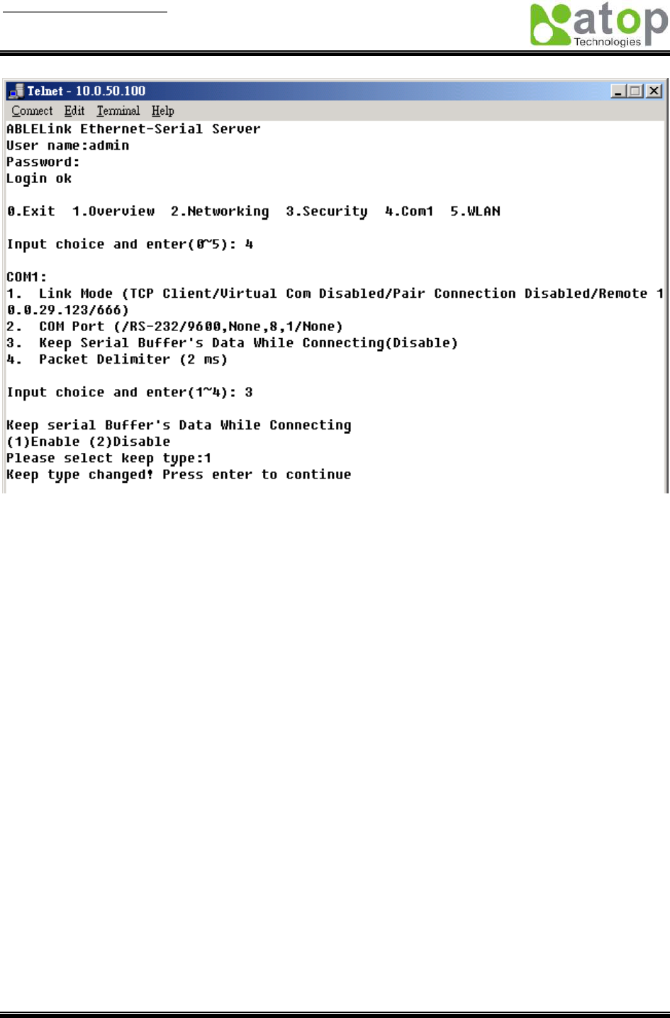
Enabling serial data buffer
Type 3 from “Input choice and enter (1~4):” of COM1, by default COM port serial data buffer is enabled
meaning that when TCP/IP Ethernet connection is broken, serial data collected from serial device will be
kept in SW2001, once TCP/IP connection is resumed, the serial data will be sent through Ethernet
connection, you can disable it if you wish.
User manual Version 1.0
ABLELink Wireless Serial Server
SW2001
Copyright © 2006 Atop Technologies, Inc.
All rights reserved. Designed in Taiwan.
20 / 51
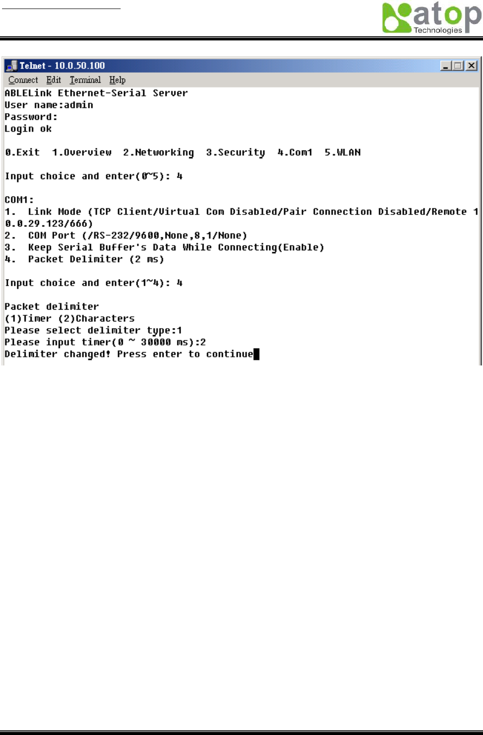
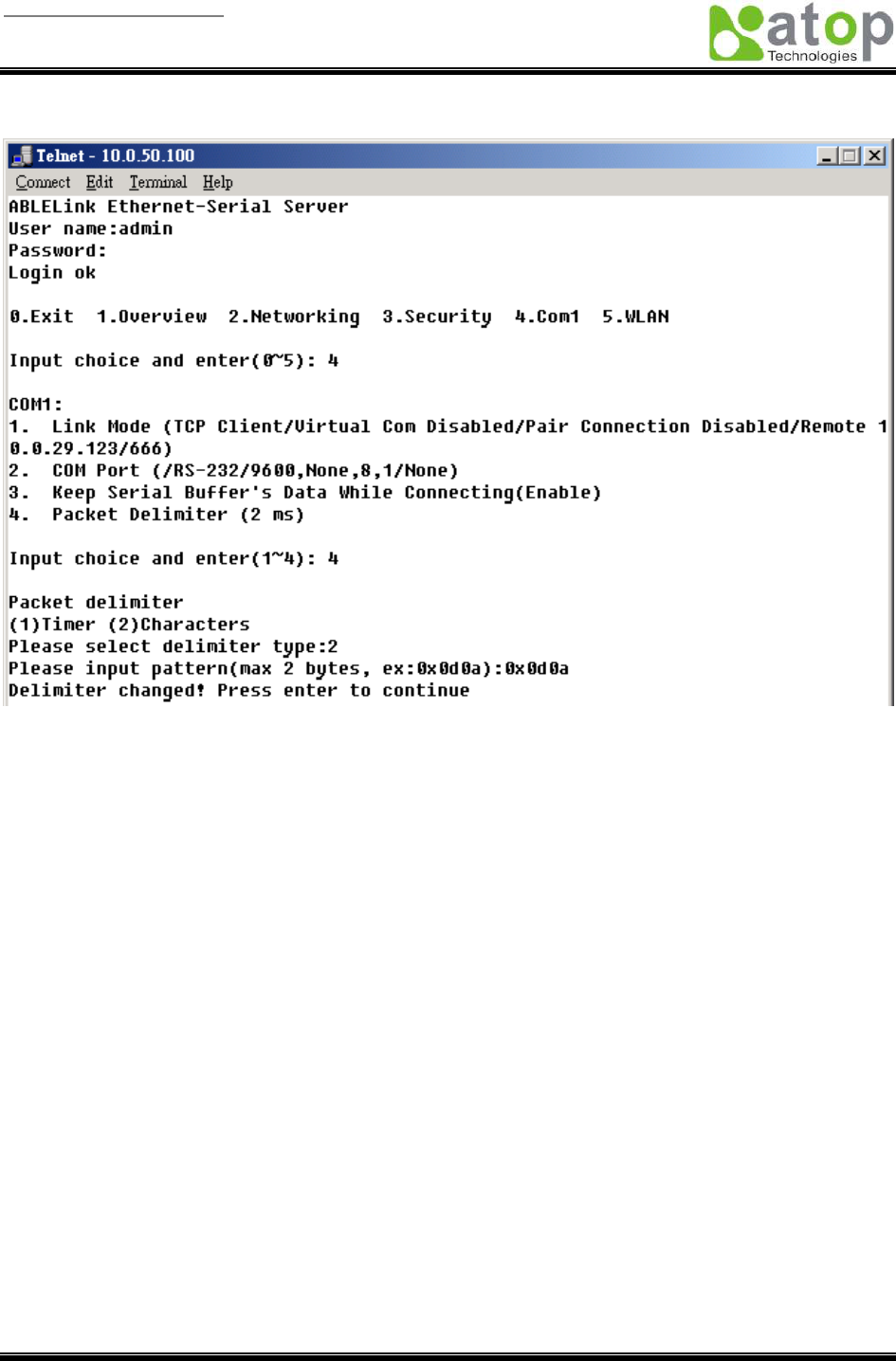
Setting packet delimiter
Packet delimiter is a way of controlling packets within serial communication. It can prevent packets from
being cut thus keep the packets complete. SW2001 provides two ways of parameter setting as inter
character timer and terminator. By default packet delimiter timer is 0 ms, you can change timer shown in
the following figure:
User manual Version 1.0
ABLELink Wireless Serial Server
SW2001
Copyright © 2006 Atop Technologies, Inc.
All rights reserved. Designed in Taiwan.
21 / 51
User manual Version 1.0
ABLELink Wireless Serial Server
SW2001
Copyright © 2006 Atop Technologies, Inc.
All rights reserved. Designed in Taiwan.
22 / 51
You can also choose character pattern as the packet delimiter indicated in the following figure:
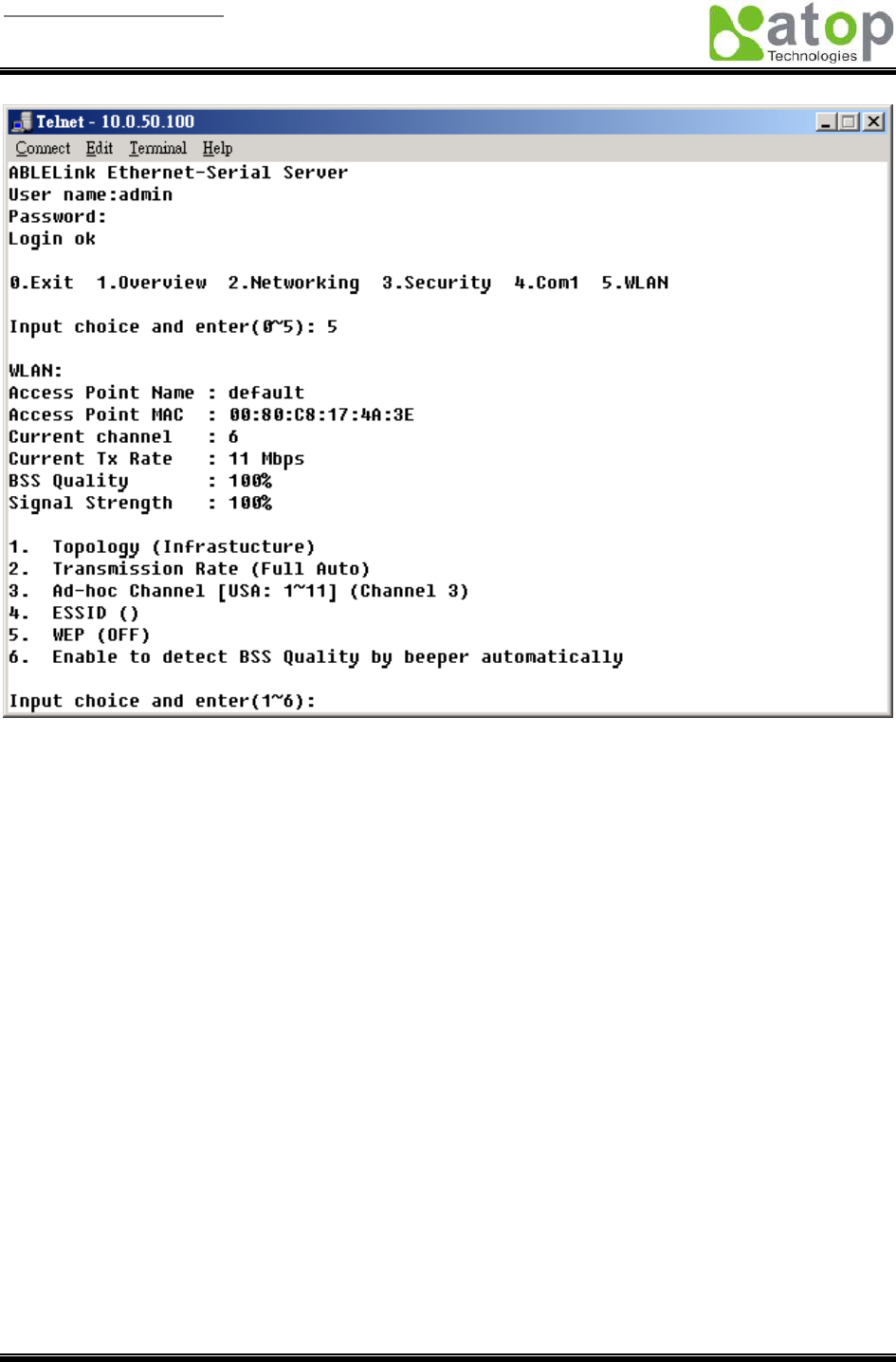
Accessing Wireless LAN setting
Select “5” from “Input choice and enter (0~5):” the following screen appears.
User manual Version 1.0
ABLELink Wireless Serial Server
SW2001
Copyright © 2006 Atop Technologies, Inc.
All rights reserved. Designed in Taiwan.
23 / 51
The above page gives you the general information about SW2001 wireless configurations including the
access point it connects to, the current channel and transmitting rate it communicates with the other
wireless devices, topology it uses, and what the ESSID (extended service set identifier) and WEP
(wireless encryption protocol) are if you use them.
User manual Version 1.0
ABLELink Wireless Serial Server
SW2001
Copyright © 2006 Atop Technologies, Inc.
All rights reserved. Designed in Taiwan.
24 / 51
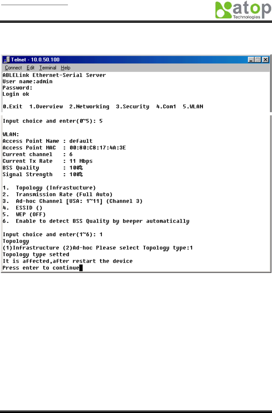
Wireless LAN topology
You can choose either infrastructure or ad-hoc mode for SW2001 as indicated in the following figure:
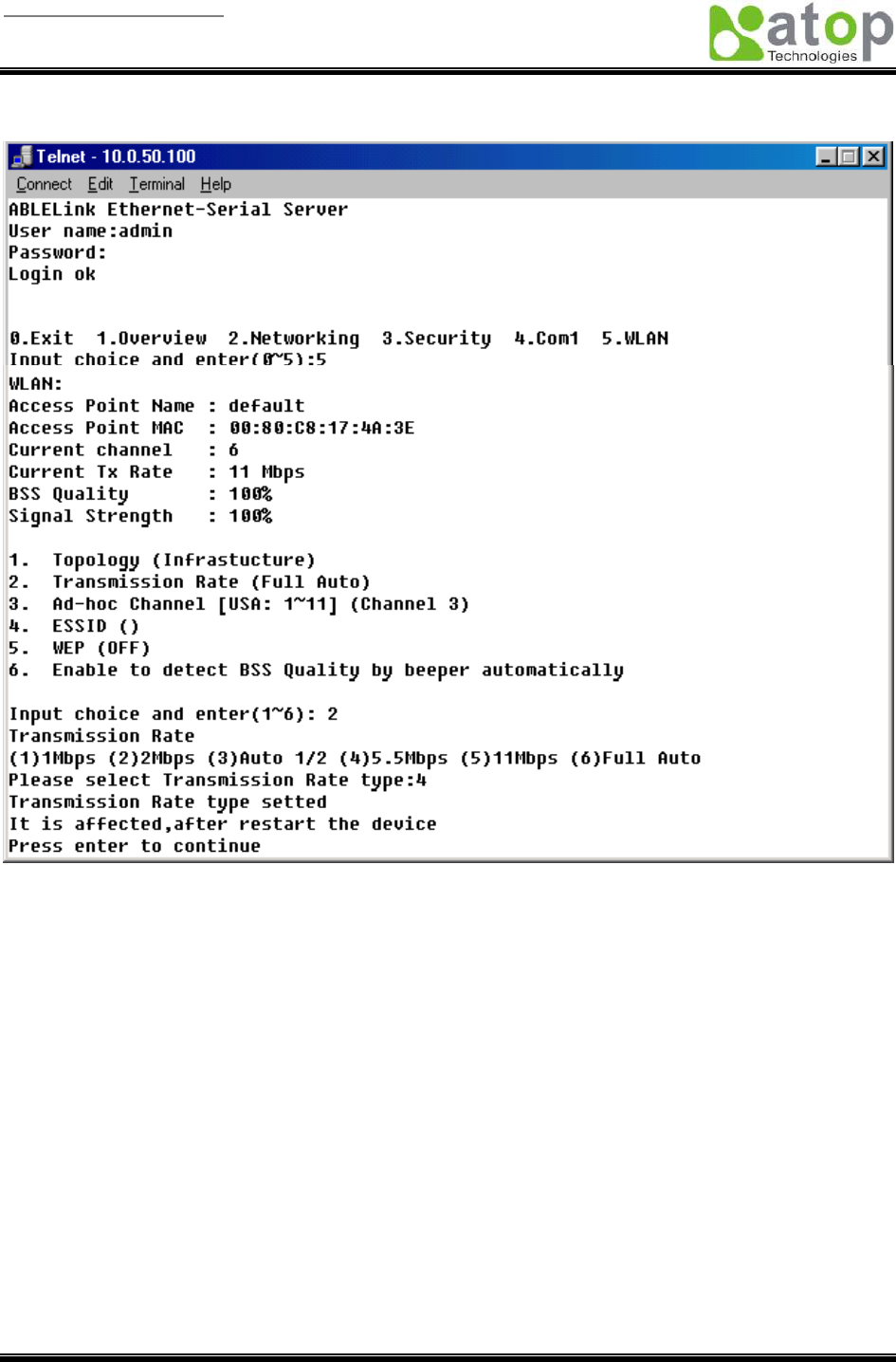
Wireless LAN Transmission Rate
You can set SW2001 transmission rate as 1 Mbps, 2Mbps, 5.5Mbps, 11Mbps, or full auto based on 802.11
standard shown in the following figure:
User manual Version 1.0
ABLELink Wireless Serial Server
SW2001
Copyright © 2006 Atop Technologies, Inc.
All rights reserved. Designed in Taiwan.
25 / 51
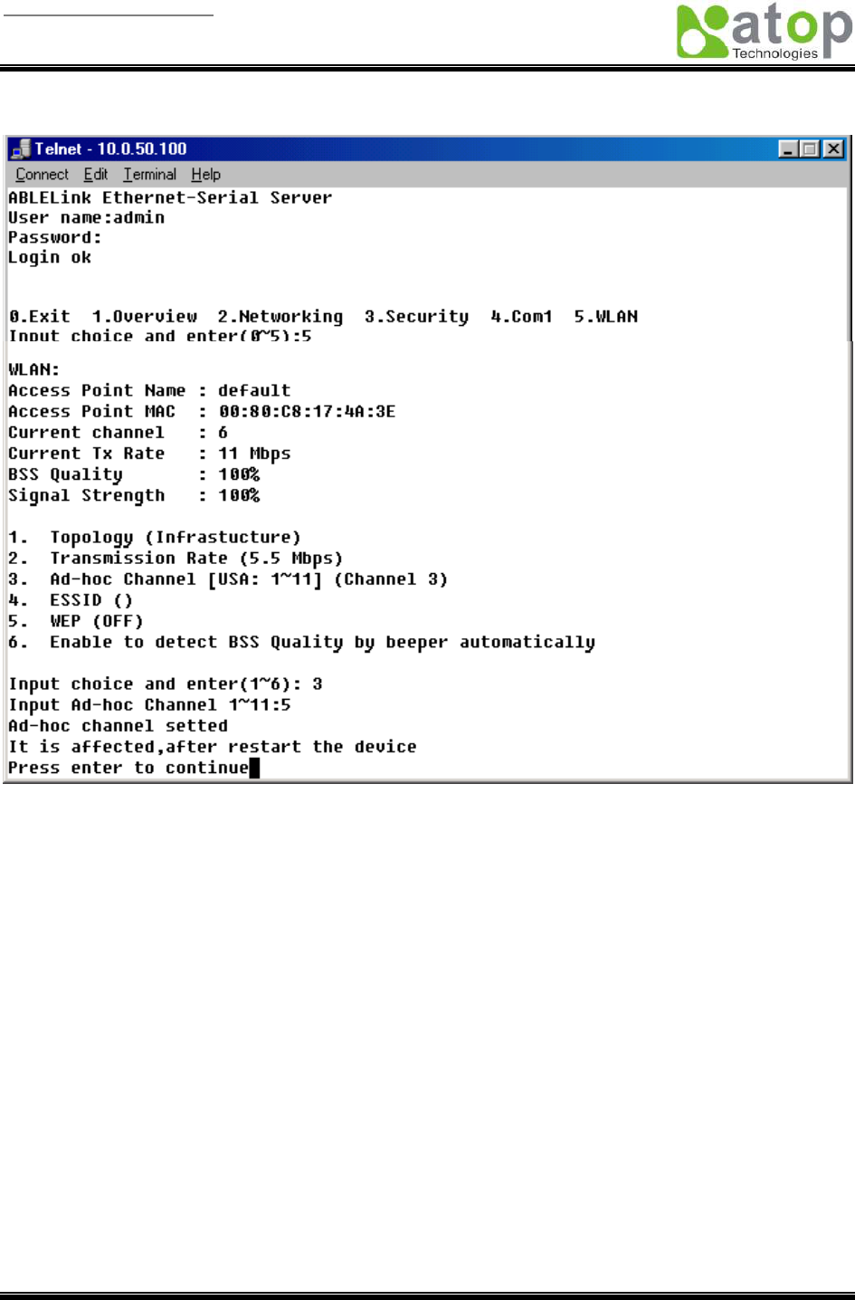
Wireless LAN Ad-hoc channel
You have to select the same channel for two wireless devices to talk to each other as indicated in the
following figure:
User manual Version 1.0
ABLELink Wireless Serial Server
SW2001
Copyright © 2006 Atop Technologies, Inc.
All rights reserved. Designed in Taiwan.
26 / 51
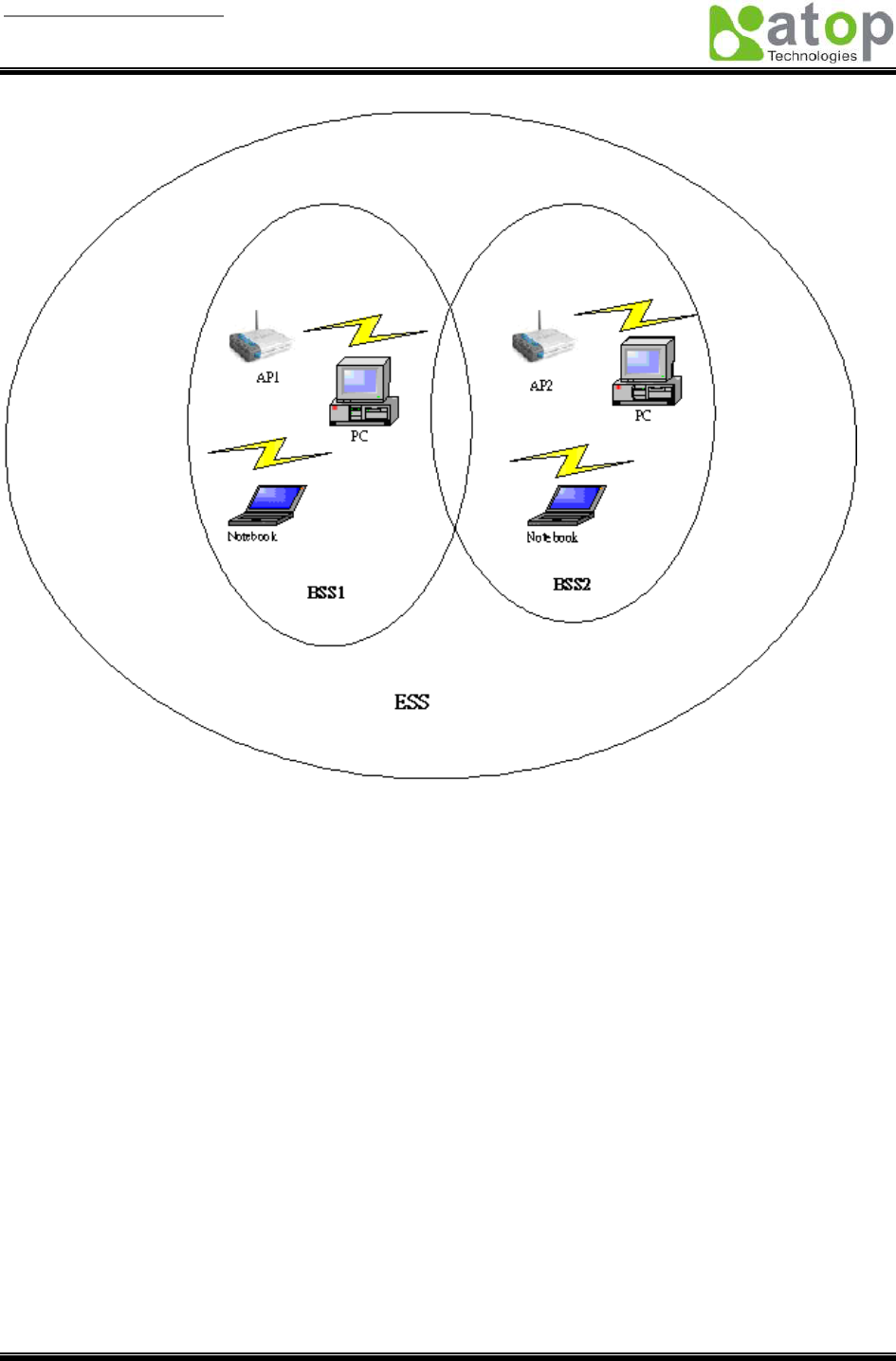
Wireless LAN ESSID
ESSID (extended service set identification) is used to identify all of the computers in the wireless LAN
system, it is different from BSSID (basic service set identification) which contains a single access point
(AP) and several other nodes. The following diagram illustrates this concept:
User manual Version 1.0
ABLELink Wireless Serial Server
SW2001
Copyright © 2006 Atop Technologies, Inc.
All rights reserved. Designed in Taiwan.
27 / 51
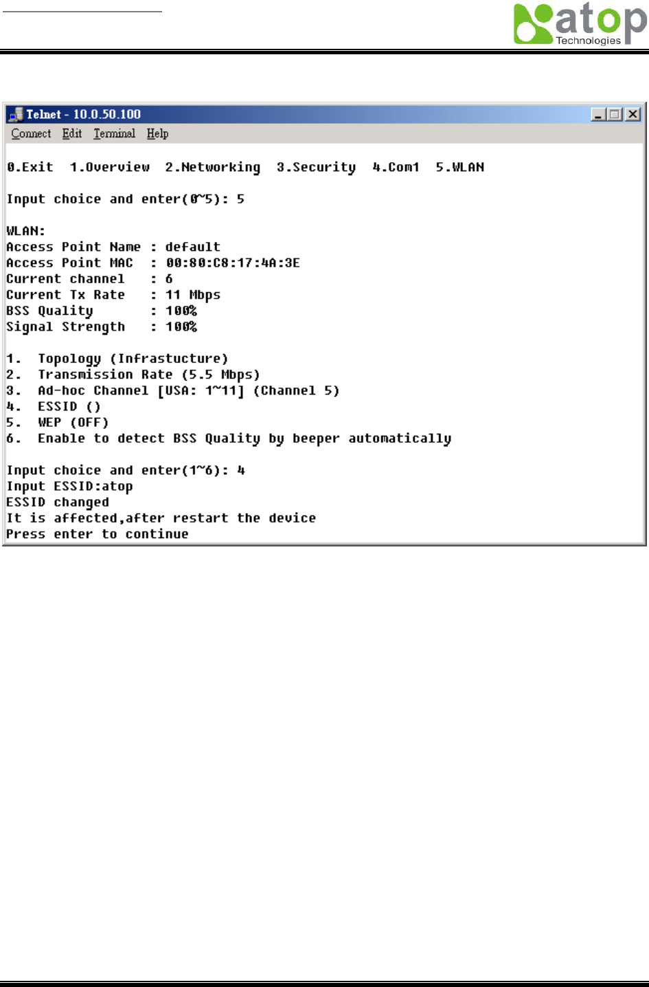
By default, SW2001’s ESSID is NULL meaning that it can connect to any access point it detects
regardless of SSID of the access point. However if there are two access points within the coverage of
SW2001, it will not connect to either of them, in this case you have to specifically input the ESSID of one
of the access points for connection. From telnet you can input ESSID as indicated in the following figure:
User manual Version 1.0
ABLELink Wireless Serial Server
SW2001
Copyright © 2006 Atop Technologies, Inc.
All rights reserved. Designed in Taiwan.
28 / 51
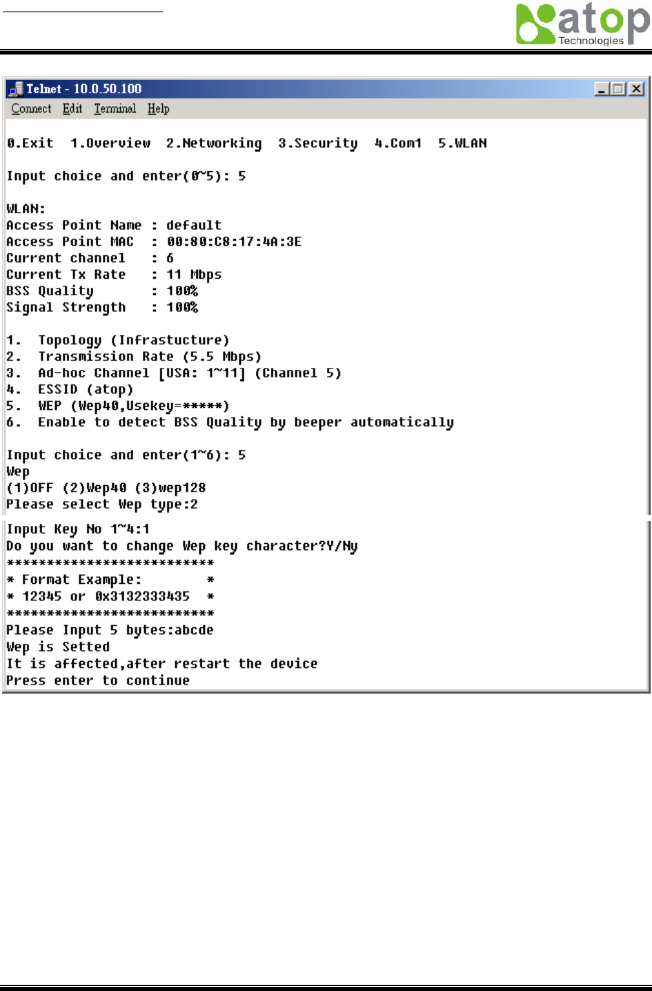
Wireless Encryption Protocol or Wired Equivalent Protocol ( WEP ) Setting
For security reason, SW2001 can set up to use WEP key of 40 bits or 128 bits to securely communicate in
the wireless network. Telnet WEP key set up screen is as following:
User manual Version 1.0
ABLELink Wireless Serial Server
SW2001
Copyright © 2006 Atop Technologies, Inc.
All rights reserved. Designed in Taiwan.
29 / 51
User manual Version 1.0
ABLELink Wireless Serial Server
SW2001
Copyright © 2006 Atop Technologies, Inc.
All rights reserved. Designed in Taiwan.
30 / 51
4.4 Configuration set by web browser
It is also possible to modify various settings through the web server interface. To do so, please follow the
steps below.
Log in to the system
1. From web browser, type in the IP address of SW2001 in the URL.
Example: http://10.0.50.100
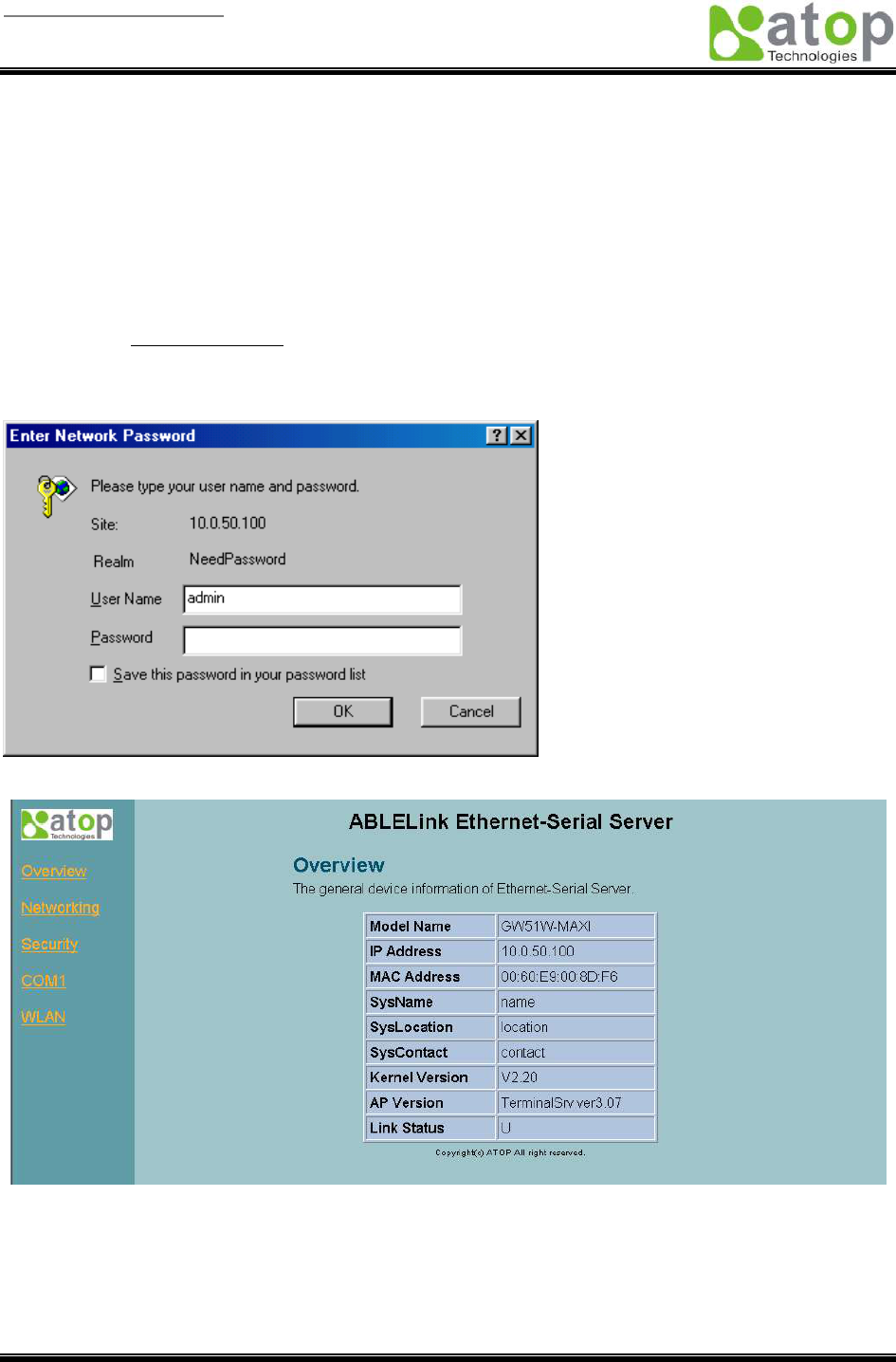
2. The following authentication screen appears. Please type in user name and password then click on
“OK”. The user name is admin and password is null by default.
3. The following overview page appears.

User manual Version 1.0
ABLELink Wireless Serial Server
SW2001
Copyright © 2006 Atop Technologies, Inc.
All rights reserved. Designed in Taiwan.
31 / 51
Change the password
1. Click on the “Security” link and the following screen appears.
2. Please input the old password in the “Old Password” field, input the new password in the “New
Password” and the “Verified Password” fields. Then click on “Save Configuration” to update the
password.
Note: You can press the default key of product to reset password to the default value.
User manual Version 1.0
ABLELink Wireless Serial Server
SW2001
Copyright © 2006 Atop Technologies, Inc.
All rights reserved. Designed in Taiwan.
32 / 51
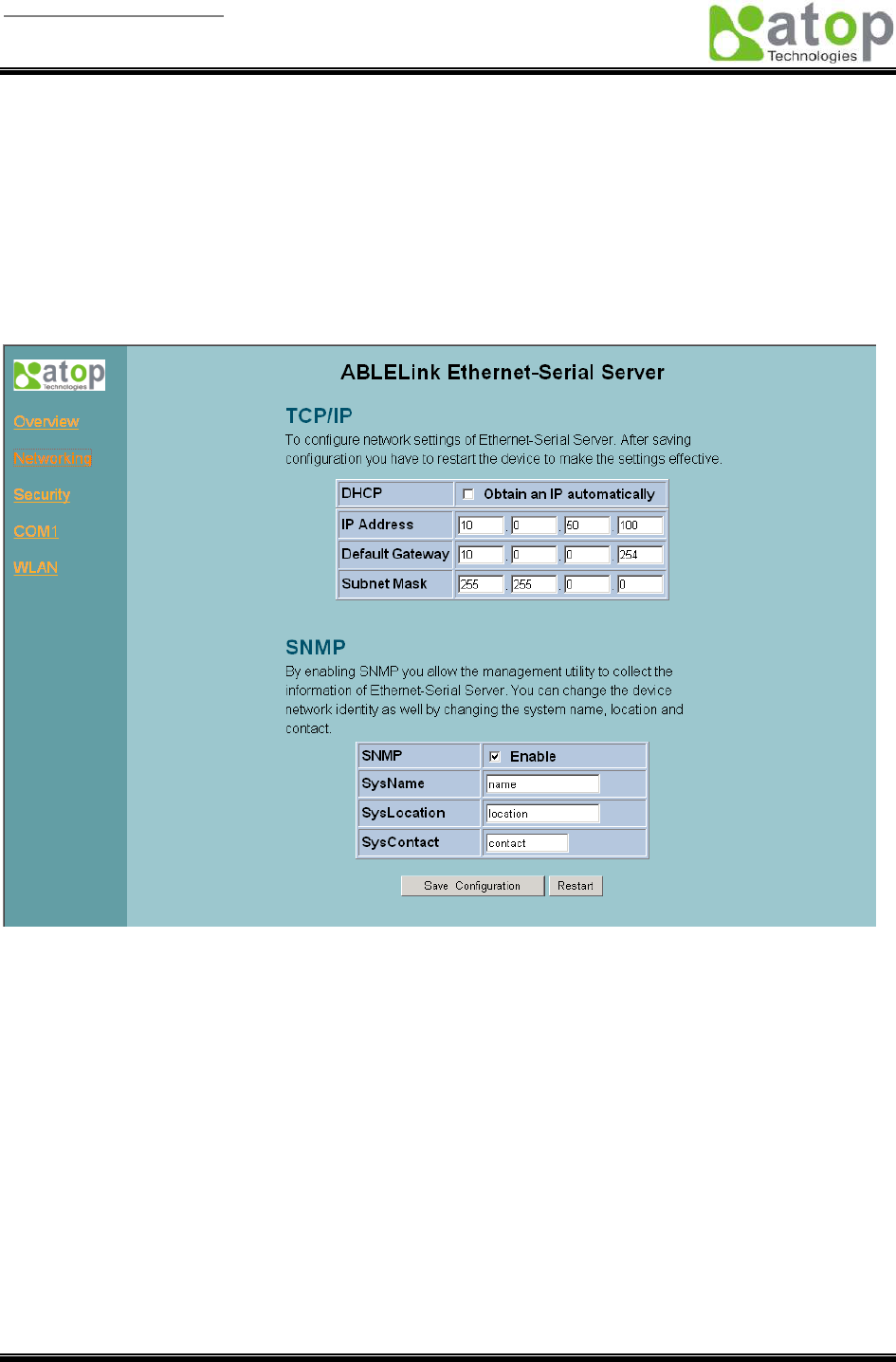
Network setup
Click on the “Networking” link and the following screen appears. Fill in IP information under TCP/IP field.
Alternatively, you can do the configuration by putting a check on DHCP to obtain auto IP address,
gateway and subnet mask information.
Enable SNMP by checking “Enable”, fill in network identification information under SNMP field and click on
the “Save Configuration” button to save the changes, please notice that the setting will not become
effective until you restart SW2001.
User manual Version 1.0
ABLELink Wireless Serial Server
SW2001
Copyright © 2006 Atop Technologies, Inc.
All rights reserved. Designed in Taiwan.
33 / 51
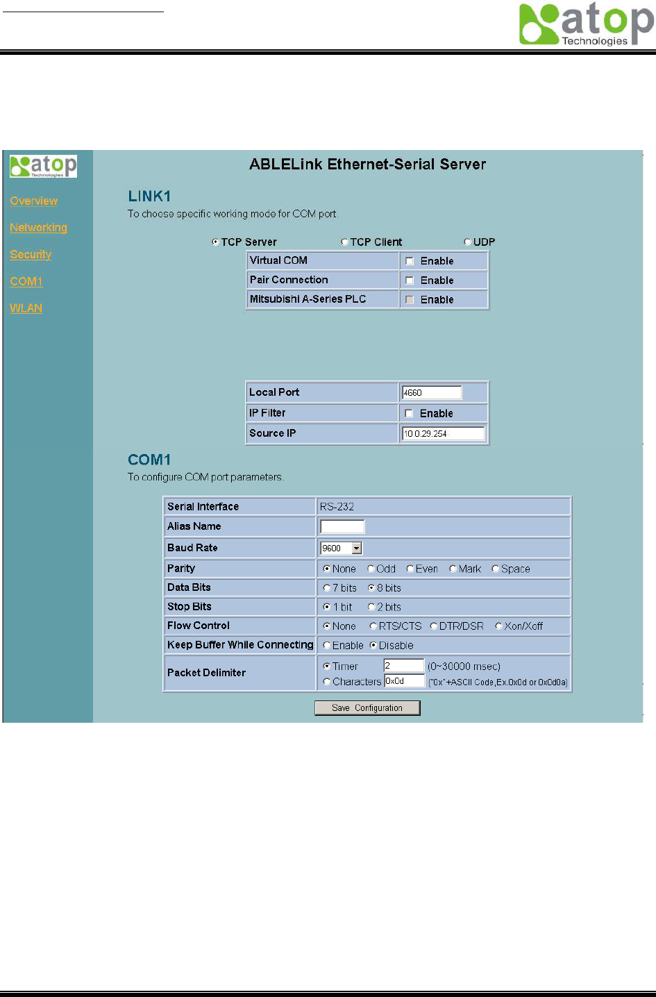
COM1 Setup
Click on the “COM1” link and the following screen appears. Fill in COM1 parameter information under
COM1 field then click on “Save Configuration” button to save the changes.
User manual Version 1.0
ABLELink Wireless Serial Server
SW2001
Copyright © 2006 Atop Technologies, Inc.
All rights reserved. Designed in Taiwan.
34 / 51
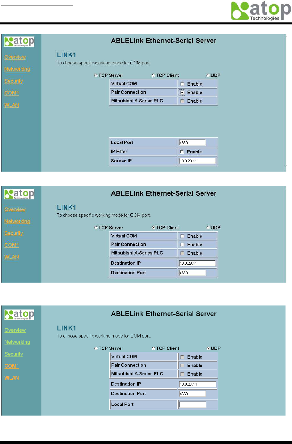
LINK1 Setup
1. Click on the “COM1” link and the following screen appears, you can configure SW2001 as
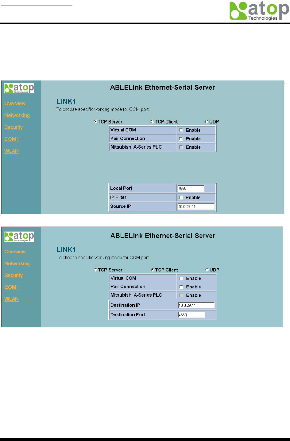
transparent mode by default. Configure SW2001 as TCP server and the local port is 4660, IP filter is
disabled by default, if IP filter is enabled, only source IP 10.0.29.11 can connect to SW2001.
Configure SW2001 as TCP client, the destination IP is 10.0.29.11, destination port is 4660.
Pair Connection
In the case of the serial connection is established with two or more SW2001 to send data over Ethernet
network, i.e. pair connection mode, you can choose “pair connection” which is indicated in the following
figure to cope with any type of serial device.
User manual Version 1.0
ABLELink Wireless Serial Server
SW2001
Copyright © 2006 Atop Technologies, Inc.
All rights reserved. Designed in Taiwan.
35 / 51
Configure SW2001 as TCP client, the destination IP is 10.0.29.11, destination port is 4660.
Configure SW2001 as UDP mode. Local port is 666, destination IP is 10.0.50.100 and destination port is
4660.
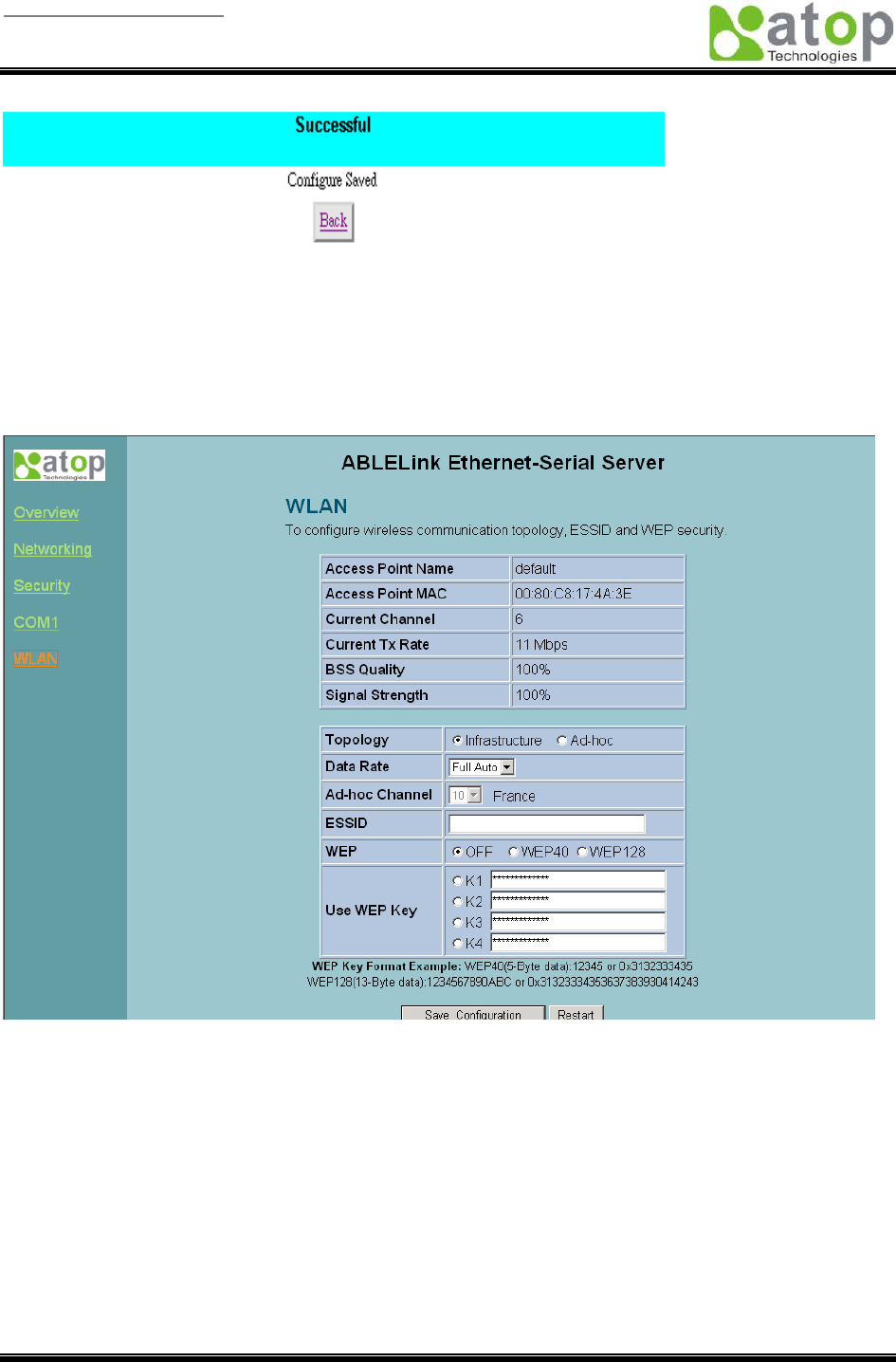
2. Click on “Save Configuration” to save the changes.
3. If the update is successful, the following screen appears.
User manual Version 1.0
ABLELink Wireless Serial Server
SW2001
Copyright © 2006 Atop Technologies, Inc.
All rights reserved. Designed in Taiwan.
36 / 51
Wireless LAN Setup
You can configure wireless LAN parameters through web pages, the following page gives you the
information of the access point SW2001 is connected to, it also allows you to configure SW2001’s
wireless topology, ESSID and WEP security. In addition, the BSS Quality and Signal Strength will indicate
you the situation of signal.
User manual Version 1.0
ABLELink Wireless Serial Server
SW2001
Copyright © 2006 Atop Technologies, Inc.
All rights reserved. Designed in Taiwan.
37 / 51
4.5 Virtual COM Mode
Virtual COM driver mode for windows converts COM data to IP data to control the RS-232C port on a
SW2001 via the IP. By creating Virtual COM ports on the PC, Atop Virtual COM redirects the
communications from the Virtual COM ports to an IP address and port number on a SW2001 that
connects the serial line device to the network. The following figure is Atop Virtual COM connection
diagram.
Physical COM1
Physical COM2
COM3
(Virtual COM Port)
COM4
(Virtual COM Port)
COM5
(Virtual COM Port)
COM6
(Virtual COM Port)
OS Driver Level
COM256
(Virtual COM Port)
PC
:
:
HUB
TCP/IP Network
Serial Line
Serial Device 1
Serial Line
Serial Device 2
Serial Line
Serial Device 3
Serial Line
Serial Device 4
SW5001-WgN1
4.5.1 Setup of a Virtual COM driver
Pre-installation requirements
Please check the operation system on your PC complied with the following requirements:
• Processor: Intel-compatible, Pentium class
• Operation system: Windows Server 2003, Windows XP, Windows 2000, Windows NT 4.0
SP5 or later, Windows Me, Windows 98, Windows 95, Microsoft NT/2000 Terminal Server,
Citrix MetaFrame
• Windows Installer 2.0
• Network: Microsoft TCP/IP networking software
User manual Version 1.0
ABLELink Wireless Serial Server
SW2001
Copyright © 2006 Atop Technologies, Inc.
All rights reserved. Designed in Taiwan.
38 / 51
Applying to the serial server
Cautions on Use
Atop Virtual COM supports firmware AP v3.4 and above of ABLELink Wirless Serial Servers.
Limitation
Atop Virtual COM driver provides user to select up to 256 COM ports as Virtual COM ports in a
monitoring PC. User can select them from a list of COM ports, which is from COM1 up to COM256.
Installation
Make sure you have turned off all anti-virus software before beginning the installation. Run
AtopVcom.exe program included in the CD to install Atop Virtual COM for your operating system.
In the end of the installation, please select one or two COM ports to become the Virtual COM ports.
Uninstalling
1. From Windows Start menu select Setting, Control Panel, Add/Remove Programs.
2. Select Serial IP for ATOP in the list of installed software.
3. Click the Add/Remove button to remove the program, or From Windows Start menu select
Programs, Serial IP for ATOP, Uninstall Serial IP for ATOP to remove the program.
4.5.2 Virtual COM communication
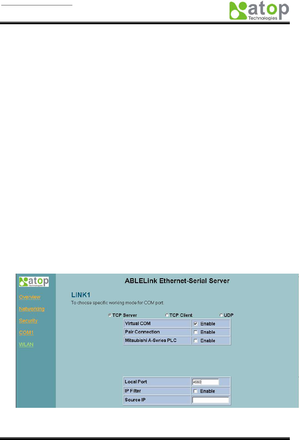
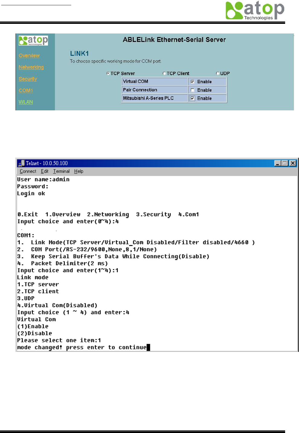
4.5.2.1 Enable Virtual COM on SW2001
From web browser access to SW2001 by typing its IP address, click on COM1 link to access COM1
page, on the top half of the page click on “TCP Server” and enable Virtual COM by putting a check
in front of the “Enable” button, then type in the local port number in the “Local Port” field as
indicated in the following figure:
For the users of Mitsubishi A-Series PLC, it may be recommended to enable “Mitsubishi A-Series
PLC” in the case of some connection problems occurred.
User manual Version 1.0
ABLELink Wireless Serial Server
SW2001
Copyright © 2006 Atop Technologies, Inc.
All rights reserved. Designed in Taiwan.
39 / 51
Or you can enable Virtual COM through telnet configuration by setting COM1 as TCP server, and
type in the local port number for COM1, then enable virtual COM as shown in the following figure:
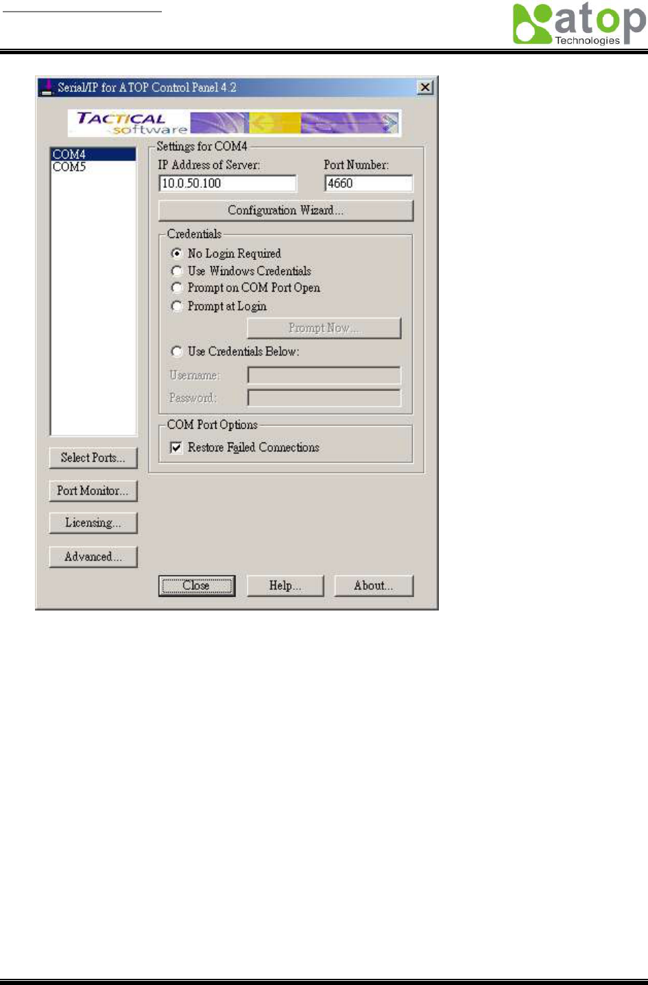
4.5.2.2 Run Serial/IP for ATOP program on monitoring PC
In the Window Start Menu, select the Serial/IP for ATOP program group and select Serial/IP for
ATOP Configuration. The configuration window is shown as following:
User manual Version 1.0
ABLELink Wireless Serial Server
SW2001
Copyright © 2006 Atop Technologies, Inc.
All rights reserved. Designed in Taiwan.
40 / 51
At right is a sample Virtual COM Control Panel window. At the left is the list of the COM ports that
you have selected (in the Select Ports window) for use by the Virtual COM Redirector. If you wish to
change which ports appear in this list, use the Select Ports button.
Each COM port has its own settings. When you click on a COM port, the Control Panel display
changes to reflect the settings for that COM port.
Note: When you change settings for a COM port, the changes are effective immediately. There is
no separate confirmation dialog to confirm or cancel your changes.
Configuring Virtual COM Ports
You configure each Serial/IP COM port as follows:
1. Select a COM port in the list.
2. For IP Address of Server, enter a numeric IP address for the serial server.
3. For Port Number, enter the TCP port number that the serial server uses to provide its
serial ports to the network.
4. For Server Credentials, the default is No Login Required. If your serial server does
require a login by the Virtual COM Redirector, the Virtual COM Redirector needs to provide
User manual Version 1.0
ABLELink Wireless Serial Server
SW2001
Copyright © 2006 Atop Technologies, Inc.
All rights reserved. Designed in Taiwan.
41 / 51
a username and/or password every time an application tries to use the serial server.
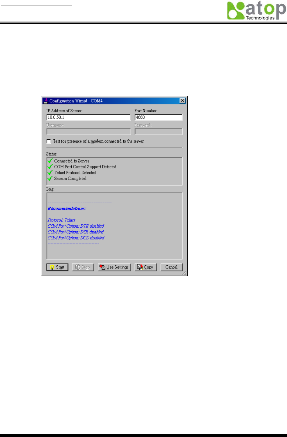
5. Click the Configuration Wizard button and then click the Start button that appears in the
wizard window. This important step verifies that the Virtual COM Redirector can
communicate with the serial server using the settings you have provided. If the Log display
does not show errors, click the Use Settings button in the wizard, which makes the
recommended settings effective and returns you to the Control Panel to continue with the
following steps.
6. For Connection Protocol, the setting must match the TCP/IP protocol that the serial
server supports. The Configuration Wizard is usually able to determine the correct setting.
7. For COM Port Options, the settings must match the COM port behavior expected by the
PC application that will use this COM port. The Configuration Wizard will recommend a
combination of settings.
5. SNMP Setup
5.1 SNMP Network Management Platform
Atop SW2001 is an SNMP device that allows many popular SNMP network management platforms such
as HP OpenView and SunNet Manager to conduct monitoring on the device.
Depending on the network management tools you are using, device (SW2001) information can be
collected from running the management tools including IP address, DNS name, system descriptions and
NIC information etc.

User manual Version 1.0
ABLELink Wireless Serial Server
SW2001
Copyright © 2006 Atop Technologies, Inc.
All rights reserved. Designed in Taiwan.
42 / 51
Appendix A: SW2001 Wireless Serial Server Specifications
A.1. Hardware Specifications
Specifications
CPU 150MHz RISC with MMU support
Memory Flash: 8MB /2MB for Bootloader / SDRAM: 16MBytes.
Interface Mini-PCI Slot (for Wireless Module)
Watchdog Hardware Watchdog Reset
Debug Port CPU Build in Com.
Wireless LAN Compliance for IEEE802.11b/g
WEP 64-bit/128-bit data encryption
WPA Compatible (TKIP/AES Encryption)
Mobile for Fast Roaming
Modulation Type: CCK, DQPSK, DBPSK, OFDM (11g)
Tx Power 11b: 14 dBm / 11g: 13 dBm
Rx Sensitivity: -66 dBm @ 54 Mbps, -80 dBm @ 11Mbps
Transmission Rate: 54 Mbps (max.) with auto fallback
Transmission distance: Up to 300 meters (@12 Mbps, in open areas)
Antenna Connector: Reverse SMA
Topologies: Infrastructure, Ad-Hoc
Ethernet 10/100M LAN (for Redundancy & Configuration)
Protection: Built-in 1.5 KV magnetic isolation
Configuration with Telnet Protocol
Serial Port Support RS232/485/422 & Software Selection
Baud Rate: 1200~921Kbps
Parity Check: None/Odd/Even/Mark/Space
Data Length: 7/8 Bit
Stop Bit: 1/2
Flow Control: None/ Software/ Hardware: RTS/CTS
Terminal Block or DB9 Connector with 15KV ESD
Power Input: DC 9V-30V
Consumption: 4.5 W (Tx Mode)
Software Protocols: ICMP, IP, TCP, UDP, DHCP Client
, Telnet, DNS, SNMP, HTTP,
SMTP, SNTP
Utilities: Windows utility for Windows 98/2000/XP/2003
Virtual COM for Windows 98/2000/XP/2003
User manual Version 1.0
ABLELink Wireless Serial Server
SW2001
Copyright © 2006 Atop Technologies, Inc.
All rights reserved. Designed in Taiwan.
43 / 51
Configuration Web browser
Telnet Console
Windows utility
Mechanical HxWxD: 90mm x 45mm x 75mm
Plastic Housing for IP40 Standard
Environment Operating: 0 to 60°C (32 to 140°F), 5 to 95% RH
Storage: -20 to 85°C (-4 to 185°F), 5 to 95%RH
A.2. Software Specifications
Item Specifications
Protocol ICMP, IP, TCP, UDP, DHCP Client, Telnet, DNS, SNMP, HTTP, SMTP, SNTP
Configuration
Configuration information for both TCP/IP and serial ports is kept in the
EEPROM.
Configuration utilities of Windows 95/98/2000/NT/XP/2003 are provided for
configuring settings.
Internal Buffer Size TCP receiving buffer size = 8K bytes
TCP transmitting buffer size = 16K bytes
RS-232/RS-485 receiving buffer size = 4K bytes
RS-232/RS-485 transmitting buffer size = 4K bytes
A.3 Connector Pin Assignments
A.3.1 COM Port
1. 8 pin Mini DIN connector

User manual Version 1.0
ABLELink Wireless Serial Server
SW2001
Copyright © 2006 Atop Technologies, Inc.
All rights reserved. Designed in Taiwan.
44 / 51
Pin assignments of Mini DIN connector is shown in the following table:
Pin#
RS-232
Full Duplex
RS-485
2 wire, Half Duplex
RS-485
4 wire, Full Duplex
1
DCD N/A N/A
2
RXD N/A RxD/T+
3
TXD TxD/R+ TxD/R+
4
DTR N/A (reserved) N/A
5
SG (Signal Ground) SG (Signal Ground) SG (Signal Ground)
6
DSR N/A N/A
7
RTS RTS/R- RTS/R-
8
CTS N/A CTS/T-
9
N/A N/A(reserved for Atop
devices)
N/A
Atop provides Mini DIN connector to DB9 connector cable, the pin assignments of DB9 connector is
shown in the following table:
Pin#
RS-232
Full Duplex
RS-485
2 wire, Half Duplex
RS-485
4 wire, Full Duplex
1
DCD N/A N/A
2
RXD N/A N/A
3
TXD DATA- RXD-
4
DTR N/A (reserved) TXD-
5
SG (Signal Ground) SG (Signal Ground) SG (Signal Ground)
6
DSR N/A N/A
7
RTS N/A N/A
8
CTS DATA+ RXD+
9
RI N/A(reserved for Atop
devices)
TXD+
Note that RS-485 2 or 4 pins assignments of DB9 connector are different from those of Mini DIN connector.
User manual Version 1.0
ABLELink Wireless Serial Server
SW2001
Copyright © 2006 Atop Technologies, Inc.
All rights reserved. Designed in Taiwan.
45 / 51
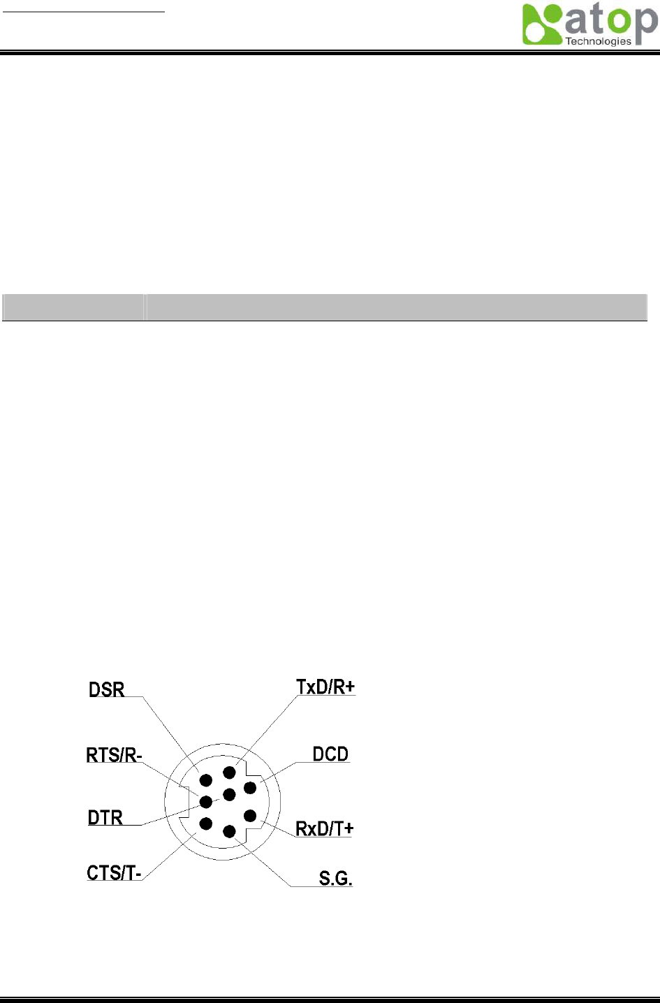
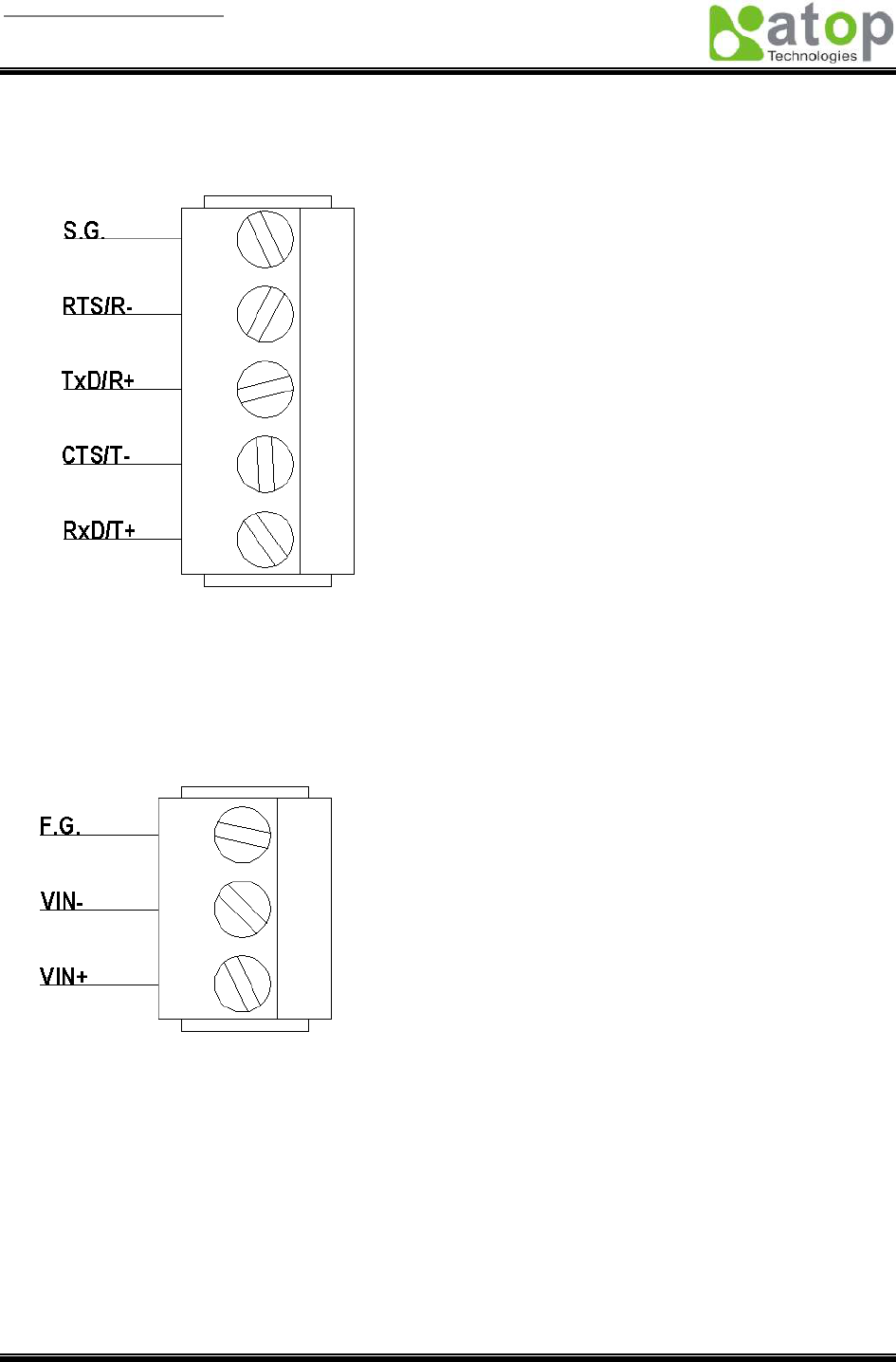
2. Terminal Block Connector
RS-485 only uses RTS/R- and TxD/R+ for data communication while RS-232 or RS-422 uses RTS/R-,
TxD/R+, CTS/T- and RxD/T+ for communicating data.
A.3.2 Power terminal block connector

User manual Version 1.0
ABLELink Wireless Serial Server
SW2001
Copyright © 2006 Atop Technologies, Inc.
All rights reserved. Designed in Taiwan.
46 / 51
A.4 LED Indication for Link Status
A.4.1 Detect SW2001 startup
“ ^ “ : Beep twice
“ = “ : Beep off
Message
Description
^==^========^^^
(5sec)
Startup OK and AP firmware is enabled
Table 1. Buzzer indication
A.4.2 Detect SW2001 Signal Strength
The BSS quality can be detected by LED indication in SW2001.
Run-time
When run-time, if the default key is pressed and then released, one of the specified actions will be down
depending on the released time after you heard how many beeps.
BSS quality is indicated by count of LEDs, which is shown as bellowed:
Blink RED
There is no signal detected
One RED
The quality is between is 0%~20%
2 LEDs
The quality is between is 20%~40%
3 LEDs
The quality is between is 40%~60%
4 LEDs
The quality is between is 60%~80%
5 LEDs
The quality is between is 80%~100%
LAN LED
Message
Description
LED Off
No data is transmitting on Ethernet
LED blinking
Data is transmitting on Ethernet
Table 2. LAN LED Message
COM Port LED

User manual Version 1.0
ABLELink Wireless Serial Server
SW2001
Copyright © 2006 Atop Technologies, Inc.
All rights reserved. Designed in Taiwan.
47 / 51
Message
Description
LED off
No data is transmitting on COM port
LED on blinking state
Data is transmitting on COM port
Table 3. COM Port LED Message
RUN LED
Message Description
LED on Jumper JP7 and JP8 are short to disable AP firmware in the flash memory.
LED blinking (rate: 0.5Sec)
AP firmware is running
Table 4. RUN LED Message
User manual Version 1.0
ABLELink Wireless Serial Server
SW2001
Copyright © 2006 Atop Technologies, Inc.
All rights reserved. Designed in Taiwan.
48 / 51
Appendix B Configuration Utility
The configuration utility monitorXX.exe (XX: Version number) comes with the product CD or diskette is
the main utility program to demonstrate and configure SW2001’s settings.
D.1 Run the utility
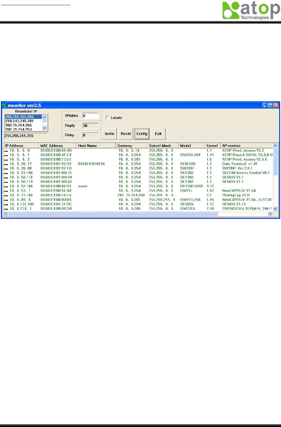
Start the program under environment and the following window appears.
D.2 Detect Operational Devices
You may do the following steps to detect devices currently available on the network.
1. Start monitorXX.exe utility program.
2. Select an item from the Broadcast IP list.
3. Specify a number in the Wishes box.
4. Click on the Invite button. This will display all the devices information you have requested.
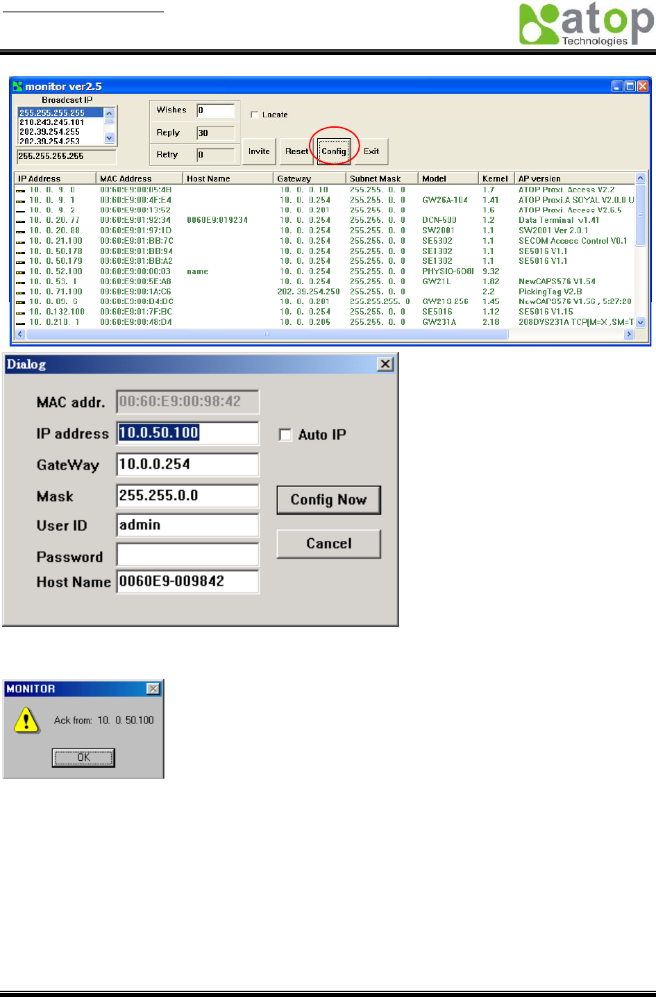
D.3 Configure Devices
You may use monitorXX.exe configuration utility to configure the settings of devices on the network. To
do so, please follow the steps below.
1. Repeat the steps in the section of D.2 to bring up the devices information.
2. Select the device you want to configure from the IP Address column, click on the Config button, a
configuration window will popup as shown in Figure D2:
User manual Version 1.0
ABLELink Wireless Serial Server
SW2001
Copyright © 2006 Atop Technologies, Inc.
All rights reserved. Designed in Taiwan.
49 / 51
3. After you click the “Configure Now” button, the target device will return an ACK message indicating
the modification is successful as shown in the following:
Please note monitor25.exe version 2.5 and above requires gw21le.dll library to function properly.

User manual Version 1.0
ABLELink Wireless Serial Server
SW2001
Copyright © 2006 Atop Technologies, Inc.
All rights reserved. Designed in Taiwan.
50 / 51
The following table lists the functional descriptions for all the fields.
Field Name
Field Descriptions
Broadcast IP
Except for the default IP 255.255.255.255, other items (IPs) are read from the file
“seg.cfg”.
This field specifies a detecting IP range. It may be a designated IP or a
broadcast IP.
Wishes
Specifies minimum number of the devices you wish to get reply from after sending an
Invite request. If there is not as many as devices responding to your invit
ation, the
system repeatedly sends invitation until your request is fulfilled.
Reply
Indicates the actual number of devices this utility program detected.
Retry
Specify the number of times that an Invite request is re-sent.
Locate
Locate the specified device.
Reset
Reset the selected device.
Config
Configure the selected device.
Exit
Exit this utility.
IP Address
Indicate the IP address of the device that replied to your request.
Ÿ Leading tag “!” stands for IP address collision, possibly cause
d by duplicated IP
addresses on the network.
Ÿ
Leading tag “?” stands for Mac address collision, possibly caused by duplicated
Mac addresses on the network.
MAC Address
Indicates the MAC address of responding device.
Gateway
Indicates the IP address of the gateway.
Subnet Mask
Indicates the TCP/IP network mask.
OS
Indicates the OS version of the responding device.
AP Version
Indicates the AP version of the responding device.
Model
Indicates the model number of the responding device. This field is
only available for
monitor.exe version 2.0 and above.