ATTOWAVE CCT278 RADAR DETECTOR User Manual CCT278 MANUAL
ATTOWAVE CO., LTD. RADAR DETECTOR CCT278 MANUAL
ATTOWAVE >
Manual
enKo products
RADAR-LASER DETECTOR
Operating Instructions
MODEL : CCT278
Thank you for purchasing enKo products radar laser detector. The CCT278
model incorporates the advanced new radar antenna technology and extremely
low power-consuming circuitry to ensure top class performance. It is a complete
integrated laser and radar detector, which responds not only to X, K and Ka band
radar guns in use today, but also the laser guns.
The CCT278 provides distinct visual and audio alerts to warn you of the presence
of X, K, Ka band and laser signals for 360° round.
You can drive with confidence when you bring along the CCT278
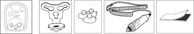
PACKAGE CONTENTS
CCT278 package includes the following components.
CCT278 radar and laser detector
Coiled 12-volt DC power cord and fuse
Windshield mounting bracket with suction cups
Dashboard mounting hook and loop fasteners
Operation manual
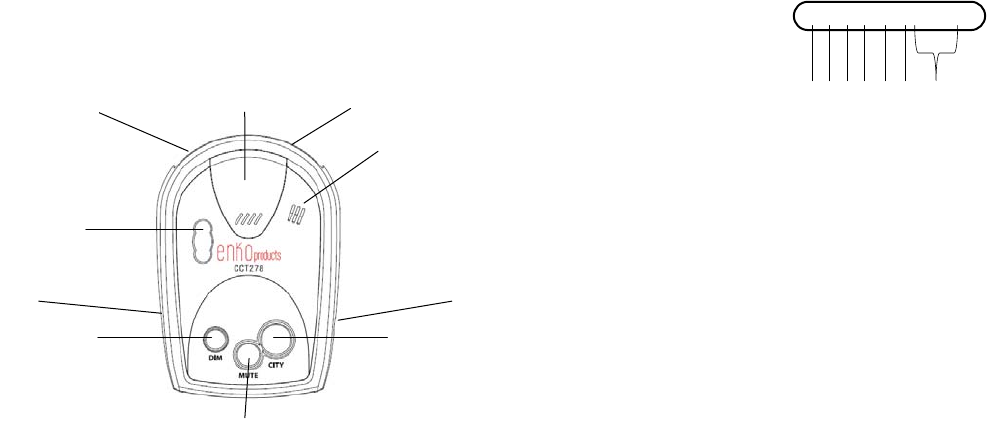
BASIC FEATURES AND CONTROLS
1. DIM mode reduces the ill umination of the display . You can adjust the
brightness of the display – Bright, Dim, Dimmer and Dark
2. Mute silences the audio alarm
3. City reduces false alarms while driving in the city. While driving on the
highways or rural areas, press the City button again to turn off the City
mode for long-range detection.
4. DC 12V Power Input
5. Buzzer hole
6. Radar Antenna Lens
7. Windshield Mounting Bracket Slot
8. Laser Lens
9. Rear Laser Lens
10. Power on-off & Volume Control Wheel
8
7
6
5
9
3
1
2
10
4
11. Highway Icon ‘H’ lights to indicate Highway mode is selected.
12. City Icon ‘C’ lights to indicate City mode is selected.
13. X Band Icon ‘X’ lights and blinks to indicate the presence of X band radar
signal. The blink rate increases as the radar source gets closer.
14. K Band Icon ‘K’ lights and blinks to indicate the presence of K band radar
signal. The blink rate increases as the radar source gets closer.
15. Ka Band Icon ‘Ka’ lights and blinks to indicate the presenc e of Ka band
radar signal. The blink rate increases as the radar source gets closer.
16. Laser Signal Icon ‘L’ lights and blinks to indicate the pres ence of laser
signal.
17. Signal Strength Meter Icon ‘2 3 4’ indicates the strength level of present
radar
INSTALLING THE UNIT
Mounting Guidelines
For the best performance, select the proper location for the detector where it has a
direct view of the road. Remember the radar antenna and laser sensor are located
behind the rear panel of the unit.
The antenna and sensors should not be obstructed by metal or metallic surfaces
and should be pointed at the horizon for accurate long-range detection.
- Choose a location that does not block the driver's vision
- Mount the detector in a level position.
- Do not mount the detector behind the metal surfaces and ornaments mirrored
sunscreen.
Tinted windows reduce the received laser signal strength.
Do not mount the detector behind tinted glass. Do not mount the detector where
the driver or passenger might hit in a sudden stop or accident.
НС
Х
ККа L2 3 4
11 12 1 3 1 4 15 1 6 1 7
Mounting Type
There are two ways of installation
Hook and Loop Mounting
The hook and loop tape included with your detector might be the best mounting
method for some dashboards.
Follow these instructions to use the hook and loop tape to mount the unit on the
dashboard.
1. Use a damp cloth to thoroughly clean the dashboard.
2. Peel off the paper backing of the tape and apply the tape to the bottom of
the detector
3. Remove the paper backing from the other side of the tape and press the
detector onto the dashboard.
Windshield Mounting
The supplied windshield bracket and suc tion cups l et y ou q uickly m ount the
detector on your vehicle’s windshield.
Follow these steps to use mounting bracket kit.
1. Install the suction cups onto the bracket by fitting them into their holes.
2. Attach the bracket to windshield.
3. Attach the detector to the bracket.
4. Bend bracket for correct detection angle.
5. Plug power cord DC12V into detector.
6. Plug power cord into cigarette lighter.
Cautions: Some new models of cars have a plastic safety coating which is applied
to the windshield. The suction cups may leave permanent marks on the wind
shield once they are re moved. Check vehicle owner’s manual to s ee if your car
has the plastic safety coating.
Connecting the Power
The CCT278 detector is designed to op erate on most DC 12V neg ative ground
vehicle ele ctrical sy stems. The power cord provided with the detector has a
cigarette lighter socket plug at one end and a small connector at the other.
1. Insert the small connector into the jack on the side of the detector.
2. Insert the other end into the cigarette lighter socket of your vehicle.
If the detector does not operate when you turn it on, remove the adapter from the
cigarette lighter socket and carefully check the socket for debris. Also, check the
fuse in the adapter and your vehicle's fuse box.
Replacing the Fuse
If the detecto r stops operating, the fuse in the cigarette lighter plug m ight be
blown. If it has blown, follow these steps to replace it:
1. To replace the fuse, unscrew the top of the plug.
2. Remove the fuse and check the fuse to see if it has blown. If it has, replace it.
OPERATION
1) Power On & Volume Control
Rotate the Power and Volume control wheel clockwise to turn the Power on/off.
This wheel can adjust volume up/down also by moving back and forth.
2) Memory
It will auto matically remember your last settings when the unit is turned off or
removed from the power. All features selected are retained in the memory except
for MUTE. Each time when power turns on, MUTE OFF will be set.
3) Display Brightness Control (Dim mode)
Dim mode r educes the il lumination of the display. Press the DIM button
repeatedly to tog gle between four leve ls of bri ghtness modes: Bright - Dim -
Dimmer – Dark
4) Highway & City mode Selection
Press the CITY button to toggle between Highway and City modes.
X-band occupied by police radar is also shared for other uses, such as automatic
door openers like t he o nes used at supe rmarkets, bur glar alarms, terrestrial
microwave emission, RF braking s ystems, and other devices. In addition, other
radar detectors in close proximity may falsely alert your detector. To reduce false
alerts, the CCT278 detector has different highwa y and city m odes. Highway
modes provide full imme diate response to all signals detect ed. City m odes
minimize unwanted false alar ms in an urban environment. When City mode is
selected, “C” icon of the display will turn on and when Highway mode is selected,
“H” icon of the display will turn on.
- Highway 1 : “H” icon on
- Highway 2 : ”H” and “2” icons on
- City 1 : “C” icon on
- City 2 : “C” and “2” icons on – Maximum filtering against urban
false signal sources.
NOTE: X band is not detected at Highway 2 and City2 modes. Some towns
and small cities may still be using X band radar.
5) Tutorial mode
The CCT278 detector has a tutorial mode intended t o familiarize you with the
various visual display s and distinct audi ble alerts tha t the unit performs. Pres s
and hold the DIM button s for 3 seconds to begi n the tutorial mode. It will
demonstrate how it operates when each radar and laser band signal is detected.
The numbers of “2”, “3”, “4” at display are called signal strength m eters when
they are used to indicate how strong a signal bein g detected is. As a signal
strength meter they are display ed t ogether with a radar band (X, K, Ka). The
higher the number, the stronger the radar signals.
6) Mute on/off Selection (Mute mode)
Press the M UTE button repeatedly to toggle between mute on and mute of f
modes. Mute on will silence the audio al arm for the rem ainder o f an existing
signal and for any new alert received.
7) Receiving and Identifying Radar
Distinctive audible alarms will be em itted for X, K and Ka band r adar signals.
The alarm sounds will occur faster and faster as the signal gets stronger (as y ou
get closer to the source). When the sig nal gets very strong, t he alarm sounds
become continuous tones.
8) VG-2 Undetectable
The VG-2, also known as a “radar detector detector”, is a special receiver used
by police to detect signals radiated by a radar detector. The CCT278 detector is
not detected by VG-2 device.
CARE AND MAINTENANCE
The CCT278 detector is an example of superior design and craftsmanship.
The following suggestions will help you to handle your detector in a proper way
so you can enjoy it for years.
Never leave the detector on the dashboard when you park your vehicle. The
temperature in the vehicle in summer can reach levels above what is considered
to be safe for this detector.
To m ake y ou less susceptible to break-in and theft, re move the detector from
your dashboard when you leave your vehicle.
Do not expose the detector to m oisture. Rain dew, road splash, or other liquids
can damage the internal components and reduce sensitivity of the detector.
FCC Information(FCC ID : W75-CCT278)
This device com plies with part 15 of FCC rules: Operation is sub ject to the
following two conditions: (1) This device may not cause harmful interference,
and (2)This device must accept any interference received including interference
that may cause undesired operation.
CAUTION: Modifications or parts not approved by enKo products may violate
FCC rules and void authority to operate this equipment.

Limited 1-Year Warranty
enKo products warrants that its products, and the component parts thereof, will
be free of defects in workmanship and materials for a period of one year from
the date of its consumer purchase.
SPECIFICATIONS
RADAR
Receiver Type: Dual Conversion Super-heterodyne
Antenna Type: Linear Polarized. Self-Contained
Antenna
Detector Type: Frequency Discriminator
Frequency of Operation: X Band 10.525 GHz ± 0.050 GHz
K Band 24.150 GHz ± 0.100 GHz
Ka Band 34.700GHz ± 1.300 GHz
(Super wide band)
LASER
Receiver Type: Pulsed Laser Signal Receiver
Detector Type: Digital Signal Processor
Opto Sensor: Photo Diode with Convex Condenser
Lens
Spectral Response : 905 nm ± 50 nm
General
Operating Temperature Range: -20 °C to 70 °C
Storage Temperature Range: -30 °C to 80 °C
Power Requirements: 12 VDC to 15 VDC, 120 mA
(Negative Ground)
*Specifications are typical. Individual units might vary.
Specifications are subject to change without notice.