ATrack Technology ATVT-1543 Tracker User Manual
ATrack Technology Inc. Tracker
UserManual.wiki
>
ATrack Technology
>
ATVT 1543 User Manual
User manual
Navigation menu
Upload a User Manual
Namespaces
Wiki Guide
HTML
PDF
Info
Views
User Manual
Discussion / Help
Navigation
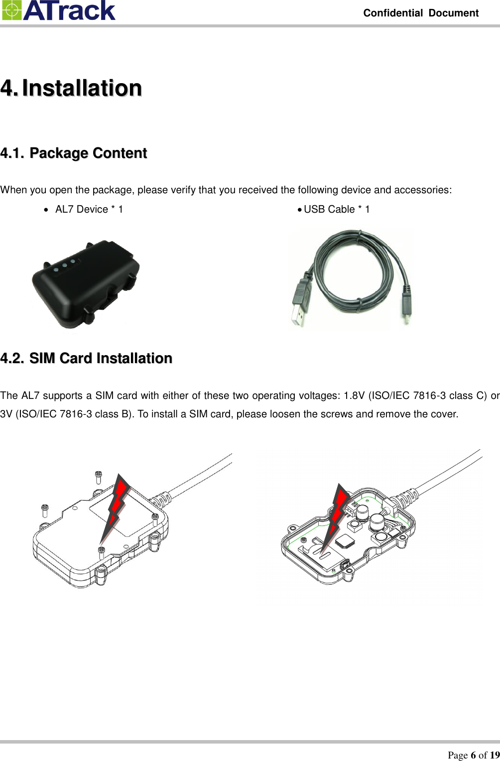
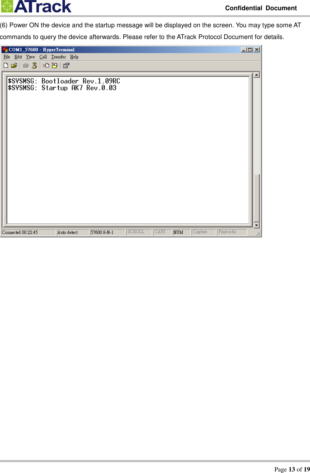
![Confidential Document Page 10 of 19 55.. CCoonnffiigguurraattiioonn You may be able to explore great features on the AL7 through AT commands. The commands can be sent to a device via USB, SMS or Mobile network (e.g. GPRS/CDMA/UMTS). The following diagram shows how to configure a device with Hyper terminal via USB. 55..11.. CCoonnnneecctt aa DDeevviiccee UUssiinngg HHyyppeerrTTeerrmmiinnaall The following example shows how to connect the AL7 through HyperTerminal. You may use other popular terminal emulators such as Putty or Tera Term Pro to establish a console session with the AL7. (1) Run HyperTerminal and select the correct COM port and click on the [Configure…] button.](https://usermanual.wiki/ATrack-Technology/ATVT-1543/User-Guide-2835641-Page-10.png)
![Confidential Document Page 11 of 19 (2) Port Settings should be as follows. Click on the [OK] button to close the Properties window. (3) Click on [File][Properties] Bits per second: 57600 Data Bits: 8 Parity: None Stop Bits: 1 Flow Control: None](https://usermanual.wiki/ATrack-Technology/ATVT-1543/User-Guide-2835641-Page-11.png)
![Confidential Document Page 12 of 19 (4) Click on the [Settings] tab and click on the [ASCII Setup…] button. (5) Check the following options and click on the [OK] button.](https://usermanual.wiki/ATrack-Technology/ATVT-1543/User-Guide-2835641-Page-12.png)
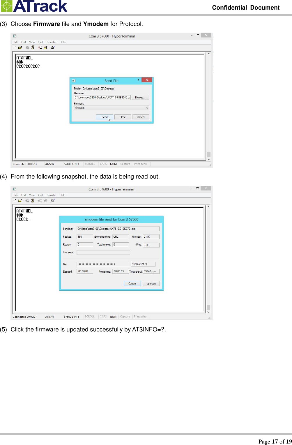
![Confidential Document Page 16 of 19 77.. FFiirrmmwwaarree UUppggrraaddee The device firmware can be upgraded via USB or through the FTP protocol. Following is an example of firmware upgrade via USB. (1) Make AL7 connecting to hyper terminal and execute AT$FWDL (2) Click on [Transfer] -> [Send File]](https://usermanual.wiki/ATrack-Technology/ATVT-1543/User-Guide-2835641-Page-16.png)