ATrack Technology ATVT1305 UMTS OBD VEHICLE TRACKER User Manual
ATrack Technology Inc. UMTS OBD VEHICLE TRACKER
UserManual.wiki
>
ATrack Technology
>
ATVT1305 User Manual
User Manual
Navigation menu
Upload a User Manual
Namespaces
Wiki Guide
HTML
PDF
Info
Views
User Manual
Discussion / Help
Navigation
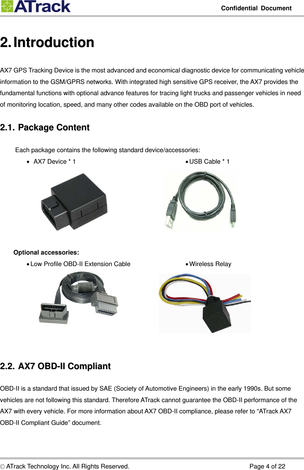
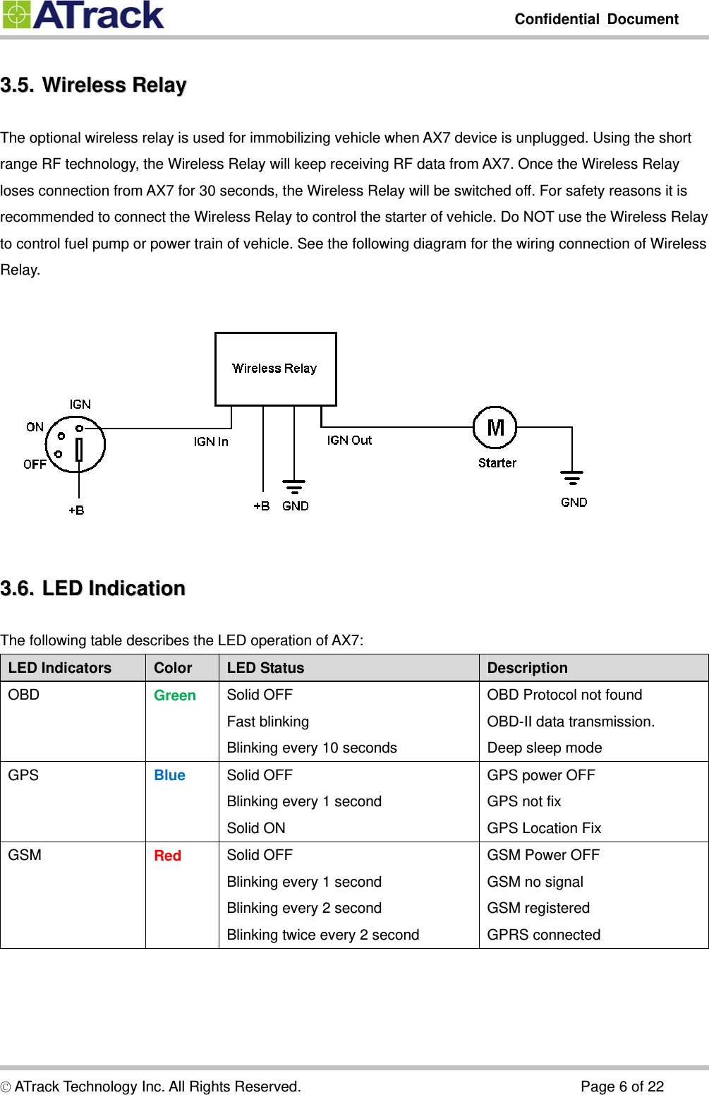
![Confidential Document © ATrack Technology Inc. All Rights Reserved. Page 10 of 22 44..22.. CCoonnffiigguurree tthhee AAXX77 ddeevviiccee The AXTool is a simple configuration tool for the AX7 device. It is useful for user to setting basic parameters into the AX7 device. For advanced users, please refer to the ATrack A-Series Protocol Document for detail descriptions. General Setting [Device Password]: The device password is used for protecting device configurations. The maximum length is 6 characters. [SIM Card PIN Code]: Enter PIN code of SIM card correctly for register to network property if enabled. [Position Format]: Select position format for all reports. [Power Saving Mode]: Enable/Disable power saving mode. When power saving mode is enabled, the AX7 device will go into deep sleep mode after 1 minute of engine off.](https://usermanual.wiki/ATrack-Technology/ATVT1305/User-Guide-2009580-Page-10.png)
![Confidential Document © ATrack Technology Inc. All Rights Reserved. Page 11 of 22 Communication Setting [GPRS Enable]: Enable GPRS communication [Socket Type]: Select TCP or UDP for GPRS communication [APN]: Access Point Name for GPRS connection. (Please contact your cellular network carrier for the information) [Host IP]: Enter the IP address or domain name of host server [Host Port]: Enter Port number of the remote host server [User Name]: The GPRS user name. (Please contact your cellular network carrier for the information) [Password]: The GPRS password. (Please contact your cellular network carrier for the information)](https://usermanual.wiki/ATrack-Technology/ATVT1305/User-Guide-2009580-Page-11.png)
![Confidential Document © ATrack Technology Inc. All Rights Reserved. Page 12 of 22 Track Setting Setting tracking interval when vehicle engine is ON. When [Time Mode] and [Distance Mode] are both selected, the tracking behavior will operate in AND condition.](https://usermanual.wiki/ATrack-Technology/ATVT1305/User-Guide-2009580-Page-12.png)
![Confidential Document © ATrack Technology Inc. All Rights Reserved. Page 13 of 22 OBD Live Data When AX7 has connected to the OBD-II port of the vehicle. The [OBD Live Data] will showing the OBD live data from OBD-II port. This viewer could help to know which OBD data can be acquired by AX7 device. System Setting The [System] setting will showing current connected AX7 device information. The [Reset/Action] function can be used to reset parameters or clear buffered messages in the AX7 device.](https://usermanual.wiki/ATrack-Technology/ATVT1305/User-Guide-2009580-Page-13.png)
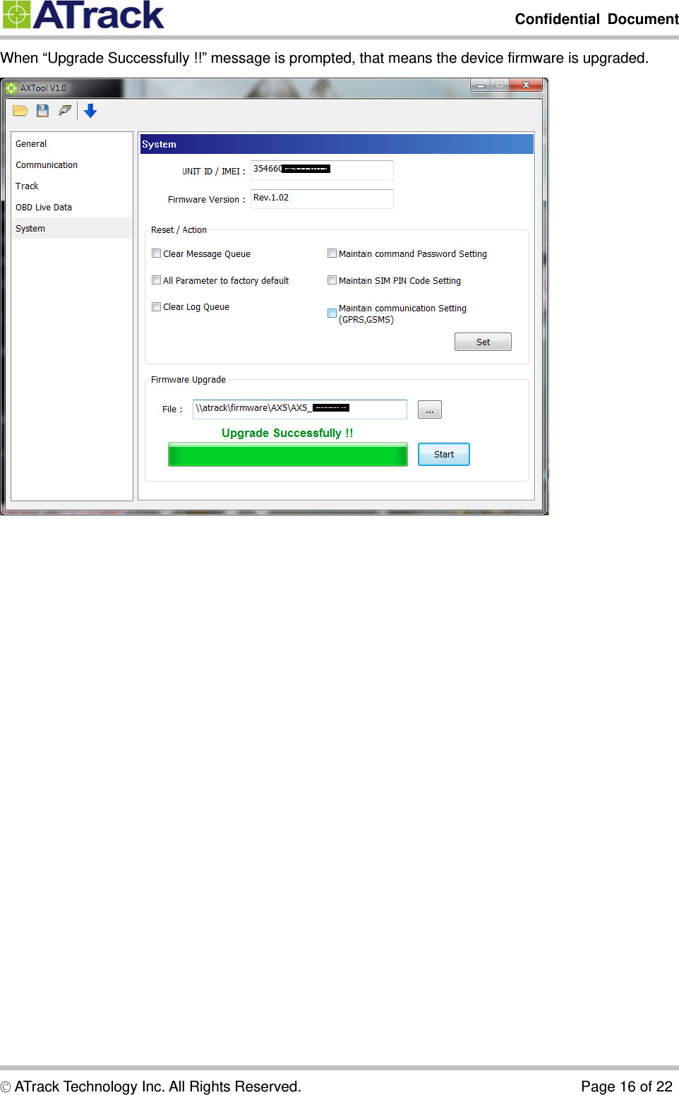
![Confidential Document © ATrack Technology Inc. All Rights Reserved. Page 15 of 22 44..33.. FFiirrmmwwaarree UUppggrraaddee Open AXTool program and click [System] item of the manu. Select firmware file which is provided by ATrack and click [Start] button. When “Waiting Device Restart…” message is prompted, please do not turn off the device.](https://usermanual.wiki/ATrack-Technology/ATVT1305/User-Guide-2009580-Page-15.png)