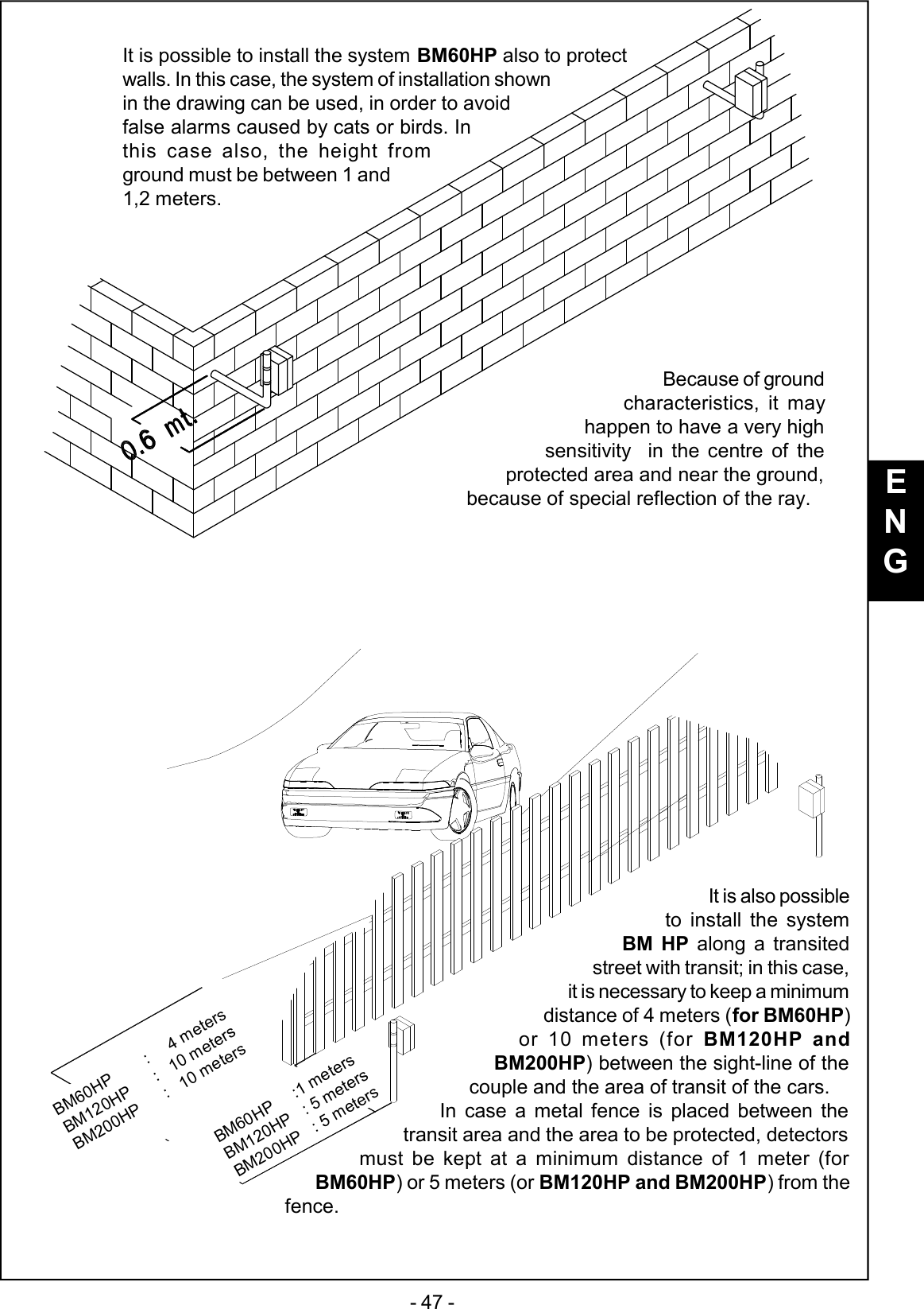
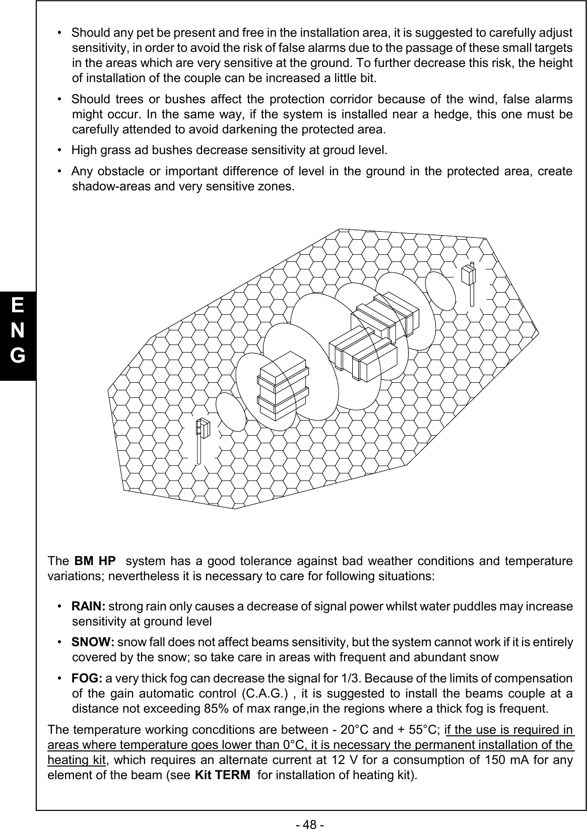
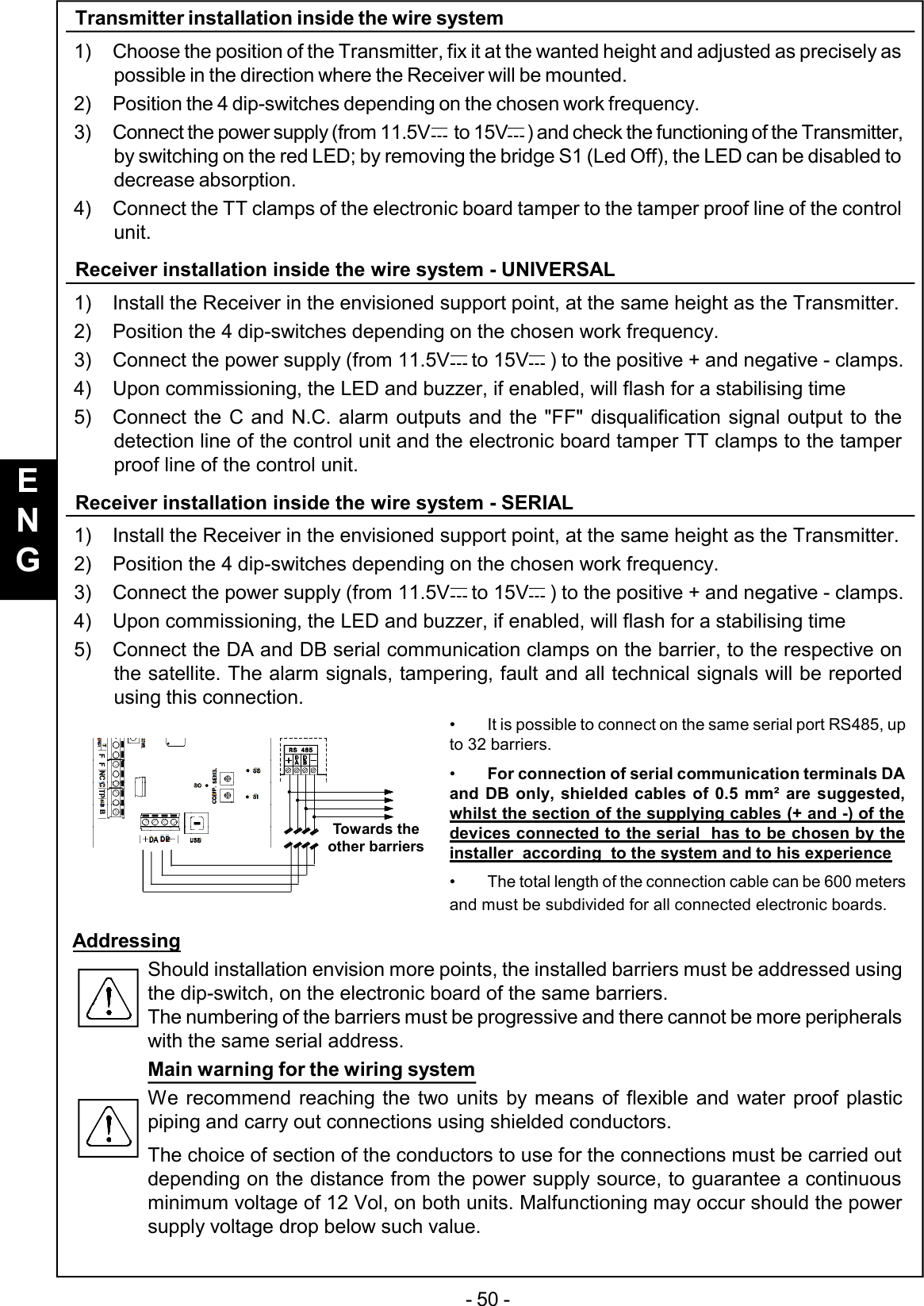
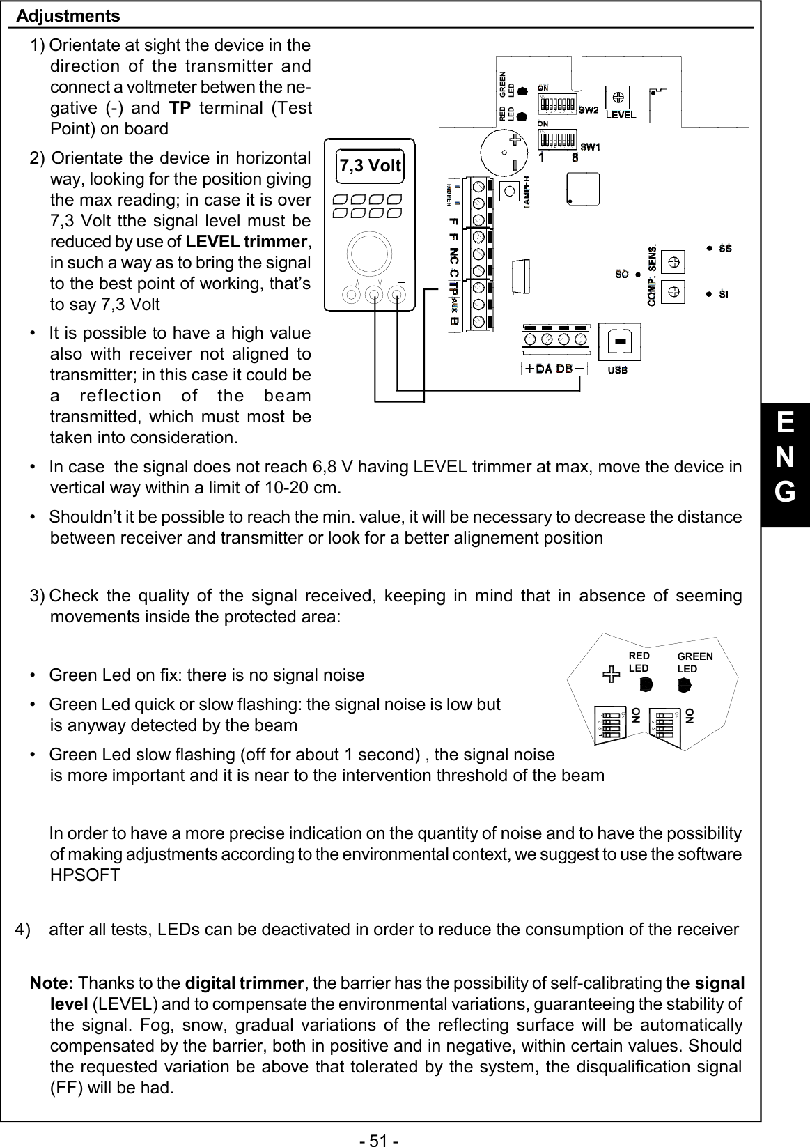
AVS Electronics 114115567 microwave barrier User Manual ist0854V1 0 Work pmd

AVS ELECTRONICS SpA microwave barrier ist0854V1 0 Work pmd

User Manual

- 35 -IST0772V2.2Curtarolo (Padova) Italywww.avselectronics.comDIGITAL MICROWAVE BEAMSFOR INDOOR AND OUTDOOR USE BM 60 HP BM 120 HP BM 200 HPCERTIFIED QUALITYSYSTEMISO9001:2008ENGBM 60 HP VACBM 120 HP VACBM 200 HP VAC
- 36 -ENGGeneral Description.................................................................................................pag. 37Transmitter................................................................................................................pag. 37BM60HP - BM120HP - BM200HP Wiring systems receiver...................................pag. 38AUX Input..................................................................................................................pag. 38Extra power supply unit for BM 60-120-200 HPVAC..............................................pag. 39DIP SWITCH - SW1...................................................................................................pag. 41Serial addresses table - SW1...................................................................................pag. 41DIP SWITCH - SW2...................................................................................................pag. 41Frequencies Table - SW2.........................................................................................pag. 41Description of working............................................................................................pag. 42 Positioning of the beams........................................................................................pag. 43Advice for installation..............................................................................................pag. 49Transmitter installation inside the wire system......................................................pag. 50Receiver installation inside the wire system - UNIVERSAL..................................pag. 50Receiver installation inside the wire system - SERIAL..........................................pag. 50Adjustments..............................................................................................................pag. 51Measurements of the signal by oscilloscope.........................................................pag. 52Sensitivity Adjustment.............................................................................................pag. 53Kit TERM (optional) Resistence fo inside heating.................................................pag. 54Kit AMP (optional) Anti-removal...............................................................................pag. 54Disqualification (Important warning)......................................................................pag. 55Optional Brackets.....................................................................................................pag. 56Special functions......................................................................................................pag. 57Detectors Management............................................................................................pag. 58Synoptic panel..........................................................................................................pag. 62Events History..........................................................................................................pag. 63Signals library...........................................................................................................pag. 65Recordings Archive.................................................................................................pag. 66System notes............................................................................................................pag. 66Upgrade Firmware...................................................................................................pag. 66Information in conformity to the Directive 1999/5/CEE for model BM_HP...........pag. 67Technical Characteristics........................................................................................pag. 68
- 37 -TAMPERB A TTS1PB1SW1LEDLEDOFFDIGITAL MICROWAVE BARRIERThe BM60HP, BM120HP and BM200HP and BM 60-120-200 HPVAC models are microwave intrusiondetection systems which functioning is based on the “field interruption” principle and, also thanks to amicroprocessor managing the digital signals, they are instruments ideal for the protection of largesurfaces, indoor and outdoor, allowing for a high degree of safety.Models BM 60-120-200 HPVAC are supplied on large containers and are equipped with a 230 V ~  1Apower supply unit and a 12 V - 0.8 Ah buffer battery (optional).General DescriptionThe system is made by a Transmitter and a Receiver which must be installed as a couple,choosing the same working frequency among the 5 available,  in both units (tx and rx) ,through SW1 (4 dip-switch module) on board.Compatibility with existing modelsIn case of replacement, choose the same frequency on the beam to be replaced (F1 by F1, F3 by F3etc.). In order to identify the corresponding frequency, use the chart “BEAMS CHANNELS”Filter of selection and compensationAny receiver is equipped with a selection filter choosing only the frequency of its channel and rejectingthe others, thus not making possible the elusion of the beam in case of use of a false transmitter.Special self-adjusting and signal-elaboration circuits have been used in the receiver for automaticcompensation of temperature variations.Detection AreaThe shape of the irradiation area is very well defined and this allows a higher possibility of detectionand a reduction of  false alarms risk.These beams are manufactured exclusively with solid-state components and are tropicalyzed inorder to obtain a very good seal against weather conditions.TransmitterThe transmitter is made of a planar microwave emitting a narrow and directional higly-stable lowpower beam.A 4-dip-switch for setting working frequency is on board.Check that the transmitter working frequency set is thesame as in the receiver coupled-supplying negative 12 V+supplying positive 12 VT T n.c. output for protection agaist detector openingS1 closedopensupplying Led enabledsupplying Led disabledBM MCHANNELSDIP DIP DIP DIP BM Q PLUSCHANNELS1 2 3 4F1 ON OFFOFFOFF GOLDF2 OFF ON OFFOFF BLUEF3 OFFOFF ON OFF SILVERF4 OFFOFFOFF ON YELLOWF5 OFFOFFOFFOFF -ENG
- 38 -BM60HP - BM120HP - BM200HP Wiring systems receiverThe Receiver is made of a high sensitivity electronic circuitcoupled with the antenna; it captivates the signal transmittedon its own channel and measures its intensity. Specialsignal processing techniques enable compensating thevariations of the surrounding environment andminimising the effect of any disturbances producedby small animals or birds.animals or birds.The electronic board contains two consoles with 8 dip-switches; the first 4 dips, of console SW2, are for thesetting of the work frequency.Check that the working frequency of thereceiver is the same as set in the transmittercoupled.AUX InputThe AUX input allows detecting the opening or not of an auxiliary detector connected to thisclamp. This input is not balanced, but is normallyclosed with negative reference.TAMPERSW1SW2TP1BFFTAMPERT T CNC AUXDBDALEDROSSOLEDVERDE8ONONCONNECTION EXAMPLETerminal board-negative power supply 12 VDA-DB serial port for serial connection in RS485+positive power supply 12 VT T output normally closed for protection against detector openingFFDisqualification signal relay; normally closed during the quiet status.This relay opens in case the signal from the Transmitter is not received for 30seconds.C / NC alarm relay exchange normally closedTP Test Point positive output for the displaying of the received signalAUX NC input for the connection of an outdoor detectorBpositive input: 12 V for stand-by; giving a positive to this clamp, the alarm relaylocks in quiet statusTrimmerLEVEL trimmer for the adjustment of the received signalSENS. trimmer for the sensitivity adjustment; increases by turning clockwiseCOMP. trimmer for the compensation adjustment; increases by turning anti-clockwiseConnectionUSB USB connector for PC and programming software connectionsENGREDLEDGREENLED
- 39 -Extra power supply unit for BM 60-120-200 HPVACTropicalised power supply unitThe power supply unit is a 15W switch with an output voltage of 13.8V and a maximum current of 1A.Fasten the two clips supplied tothe two turrets, with the Ø 4.2 x6.5 mm self-threading screwssupplied.Using the marks on the inside ofthe cover, make two 3 mm holesto fasten the power supply unit inplace.Fasten the power supply unit inplace using the two M3 x 4 screwssuppliedThe 12 V 0.8 Ah Y08A12 buffer battery (optional) (article code 1143118) (to befastened in place using the clip supplied) is housed on the lower part of theback cover of the barrier, which must never exceed the dimensions of 65 mmhigh, 96 mm wide and 25 mm deep.To connect the Y08A12 battery, use the wire supplied, with the protective fuseF 1A L250V and the connector for release if the cover comes open. If you usea different battery with the same characteristics, it is necessary to eliminate theconnector in order to connect it to the power supply unit in the most appropriateway.InstallationBoth in the receiver and the transmitter, the power supply unit must be fastened to the protectivecover of the electronic board:ENGMains power supply 100-240V~ (+/-10%) 50/60HzVoltage Rated supply voltage 13,8 VMax. current absorbed from the mains 115V~230V~ 100 mAMaximum current available Power supply unit 1AOutput voltage at 110-230V - 10% emptyWith maximum load13,8 V13,6 VOutput voltage at 110-230V + 10% emptyWith maximum load13,8 V13,6 VACCESSORIES SUPPLIEDClips 2Cable locking clips 4.5 mm wide - 120 mm long 2Wire locking clips 2.5 mm wide - 98 mm long 2Battery fastening 7.5 mm wide - 250 mm long 1Clip screws ø 4.2 - 6.5 mm long 2Power supply unit screws M3 x 4 2Buffer battery connection wire with F 1 Amp L250V fuse 1
- 40 -Insert an omnipolar network switch in the electric installation of the building.Connect the input of the mains voltage to the terminals marked L N (AC) andthe + and the - of the barrier board to those marked V+ e V- respectively.The input for the mains power supply must be connected with double insulation wiresThe 3 wires for the 230 V ~ mains power supplyand the 2 wires for the 13.8 V  power supply mustfastened securely together with their own clip(as shown in the figure) to stop them cominginto contact with sensitive parts of he barrierif they come loose from the terminal.Wire clip(use the two small onessupplied)To guarantee electric safety, the wires must befastened in place using the clip directly on theprotective sheathExternal connectionsThe power supply unit must be connected as follows:(1) V+(2) V-(3) Earth(4) Neutral 220V ~ N(5) Live 220V ~FTo be connected to the entrance ofthe TX and RX board, respecting thepolarities1  2  3  4  5Power supply12 V boardPower supply220 V ~ mainFasten the sheath of thewires in the set points,using the bigger clipssupplied.Signals to the central control unitIn the case of serial connections, inaddition to the DA and DB clips, it isnecessary to connect the powersupply negative from the powersupply unit to the central control unit,and we recommend the use of 0.5mm²section sheathed wires.In the BM 60 - 120 and 200 HPVAC barriers it is possible to feedthe TERM 1 module (Optional) (Article code 1143102) directly withthe power supply unit on the barrier, inserting a protective fuseF500mAL250V.ENG-+IN   ALIM.BATTERIA
- 41 -DIP SWITCH - SW1DIP Associated function1 .. 5 Selection serial addresses of the barrier - see addresses table6ON - Compensation activatedOFF - Compensation deactivated7ON - enables recording of the events even with lock engaged (B)OFF - events recording disabled with lock engaged(B)8ON -Active AUX input, the barrier reads the inputOFF -  Excluded AUX input, the barrier does not consider the inputDIP Associated function1 .. 4 Microwave frequency selection - see frequencies table5ON -  Enabled microwave signal quality green LEDOFF - Disabled microwave signal quality green LED6ON - Enabled alarm signal buzzerOFF - Disabled alarm signal buzzer7ON -  Enabled alarm signal red LEDOFF - Disabled alarm signal red LED8Unused, for future uses.DIP SWITCH - SW2Detector DIP1DIP2DIP3 DIP4DIP5 Detector DIP1DIP2 DIP3DIP4DIP51ON ON ON ON ON 17 ON ON ON ON OFF2OFF ON ON ON ON 18 OFF ON ON ON OFF3ON OFF ON ON ON 19 ON OFF ON ON OFF4OFF OFF ON ON ON 20 OFF OFF ON ON OFF5ON ON OFF ON ON 21 ON ON OFF ON OFF6OFF ON OFF ON ON 22 OFF ON OFF ON OFF7ON OFF OFF ON ON 23 ON OFF OFF ON OFF8OFF OFF OFF ON ON 24 OFF OFF OFF ON OFF9ON ON ON OFF ON 25 ON ON ON OFF OFF10 OFF ON ON OFF ON 26 OFF ON ON OFF OFF11 ON OFF ON OFF ON 27 ON OFF ON OFF OFF12 OFF OFF ON OFF ON 28 OFF OFF ON OFF OFF13 ON ON OFF OFF ON 29 ON ON OFF OFF OFF14 OFF ON OFF OFF ON 30 OFF ON OFF OFF OFF15 ON OFF OFF OFF ON 31 ON OFF OFF OFF OFF16 OFF OFF OFF OFF ON 32 OFF OFF OFF OFF OFFSerial addresses table - SW1BM HPBARRIERCHANNELSDIP DIP DIP DIP OLDBARRIERCHANNELS1 2 3 4F1 ON OFFOFFOFF GOLDF2 OFF ON OFFOFF BLUEF3 OFFOFF ON OFF SILVERF4 OFFOFFOFF ON YELLOWF5 OFFOFFOFFOFF -Frequencies Table - SW2ENG
- 42 -1 - 1,2 mt3 meters 3 metersThe sensitive zone shown in the drawings is tobe taken into consideration, as a big target.Overpassing this area might cause thesame perturbations as a small bodypassing the alarm area, that’s to say mightcause false alarms.BM60HP6,5 metersBM120HP10 metersBM200HP16 metersBM60HP2 metersBM120HP-BM200HP3 metersBM60HP 1,2 metersBM120HP 3 metersBM200HP 4 metersAlarm zoneSensitive zone Sensitive zoneDescription of workingThe two units (transmitter: TX and receiver: RX) must be positioned facing each other at the twoends of the distance to protect. Be aware that the nature of the ground underneath, or specialweather conditions might affect the real range.WorkingThe transmitter emits a modulated microwave signal (10,525 GHz), which is received by thereceiver and whose amplitude is compared with the programmed alarm threshold.When an intruder crosses the microwave area, it causes a signal-intensity decrease under aminimum level fixed; the receiver shows the alarm condition, lighting up a red Led indicator andopening the contat of the alarm relay.If the signal of the transmitter is not received for over 30 seconds, the alarm relay could go backto quiet condition and the negative to terminal D (disqualification) fails until signal restoring.For this reason, in the hard-wired system, it is suggested to make the connection describedin the chapter concerningdisqualification.The drawings identify thenatural shadow areas inthe immediatesorroundings of thetwo units, which extendfor about 3 meters, in atypical installation at 1 - 1,2 m height.Note: the diagrams of the patterns shown in the drawings are an indication and a guideduring installation. They do not represent the real radiation diagram of the antennas asthey may be subject to variations due to environmental context.sensitivezonesensitivezonealarmezoneBM60HP : max 60 metersBM120HP : max 120 metersBM200HP : max 200 metersENG
- 43 - Positioning of the beamsFor a correct installation of the system, choose carefully the positioning of the two units, accordingto following advice:Drawings identify the correct positioning of transmitters and receivers, in order to eliminate anypossible shadow area.The drawings here below show how one or more couples of beams have to be positioned forreaching the distance required.BE CAREFUL: only elements with different frequencies (F1, F2, F3, F4, F5) and of thesame type  (TX/TX or RX/RX) can be installed in proximity one to the other; in order toavoid interferences between transmitters and receivers belonging to different couples.The typical installation ofBM HP system  consists insorrounding the area to beprotected by use of morebeams couples in order toobtain a proper perimetricfence3 mt3 mtTX RXTX RXENG6 mt
- 44 -If, in a perimetric installation, thebeams cross the patterns, theymust always be installed inpair (2, 4, 6 etc.)It is absolutelynecessary toavoid installing  atransmitter near areceiver belongingto another coupleTX RXTX RXENG
- 45 -In order to extend the height of the protection, two couples of beamscan be installed as shown in the picture. In this case,  it issuggested to use couples of beams havingclose working frequency (two coupleswith frequency F1 and F2 or F3 andF4)BM60HP        :   1 meterBM120HP      :  10 metersBM200MHP   :  10 metersIf the fence is made of bushes or metal fencessubject to possible movement, the minimumdistance must be 1 meter for BM60HPand 10 meters for BM120HP andBM200HP.ENG
- 46 -BM60HP       :   1 meterBM120HP     :    5 metersBM200HP     :    5 metersIf a couple must be installednear a building or a fix fence, aminimum distance of 1 meter forBM60HP and 5 meters for BM120HP andBM200HP must be kept.This is required in order to avoid false alarmscaused by reflection of microwavebeam.BM60HP        :   0,6 metersBM120HP      :      2 metersBM200HP      :      2 metersA corridor large not less than 0,6 meters for BM60HPand not less than 2 meters for BM120HP andBM200HP, must be left free from obstaclesbetween transmitter and receiver; a clearvisual must always be granted in thisareaThe suggested height for the installation isbetween 1 and 1,2 meters.ENG
- 47 -It is possible to install the system BM60HP also to protectwalls. In this case, the system of installation shownin the drawing can be used, in order to avoidfalse alarms caused by cats or birds. Inthis case also, the height fromground must be between 1 and1,2 meters.Because of groundcharacteristics, it mayhappen to have a very highsensitivity  in the centre of theprotected area and near the ground,because of special reflection of the ray.BM60HP        :     4 metersBM120HP      :   10 metersBM200HP      :   10 metersIt is also possibleto install the systemBM HP along a transitedstreet with transit; in this case,it is necessary to keep a minimumdistance of 4 meters (for BM60HP)or 10 meters (for  BM120HP andBM200HP) between the sight-line of thecouple and the area of transit of the cars.In case a metal fence is placed between thetransit area and the area to be protected, detectorsmust be kept at a minimum distance of 1 meter (forBM60HP) or 5 meters (or BM120HP and BM200HP) from thefence.ENGBM60HP     :1 metersBM120HP   : 5 metersBM200HP   : 5 meters
- 48 -•Should any pet be present and free in the installation area, it is suggested to carefully adjustsensitivity, in order to avoid the risk of false alarms due to the passage of these small targetsin the areas which are very sensitive at the ground. To further decrease this risk, the heightof installation of the couple can be increased a little bit.•Should trees or bushes affect the protection corridor because of the wind, false alarmsmight occur. In the same way, if the system is installed near a hedge, this one must becarefully attended to avoid darkening the protected area.•High grass ad bushes decrease sensitivity at groud level.•Any obstacle or important difference of level in the ground in the protected area, createshadow-areas and very sensitive zones.The BM HP  system has a good tolerance against bad weather conditions and temperaturevariations; nevertheless it is necessary to care for following situations:•RAIN: strong rain only causes a decrease of signal power whilst water puddles may increasesensitivity at ground level•SNOW: snow fall does not affect beams sensitivity, but the system cannot work if it is entirelycovered by the snow; so take care in areas with frequent and abundant snow•FOG: a very thick fog can decrease the signal for 1/3. Because of the limits of compensationof the gain automatic control (C.A.G.) , it is suggested to install the beams couple at adistance not exceeding 85% of max range,in the regions where a thick fog is frequent.The temperature working concditions are between - 20°C and + 55°C; if the use is required inareas where temperature goes lower than 0°C, it is necessary the permanent installation of theheating kit, which requires an alternate current at 12 V for a consumption of 150 mA for anyelement of the beam (see Kit TERM  for installation of heating kit).ENG
- 49 -Advice for installation•Use special care for thecables entry, in order to avoidmoisture and rain penetratinginside the box.•For cable entry inside thecovers of board protection, use thecable-loops given within (as shown in thedrawing)•In the hard-wired system use anti-fire shielded cable (2 x 0,75 mm² + 8 x 0,22 mm²)In the wireless system, connect the support pole to ground  and use an additionalshield for the supplying cable 220 V ~ inside the pole, in order to create a doubleisolation.•Before installing the support poles in a definitve way, it is suggested to make a trail installationin order to find out the best position of alignement for the best effective detection:1Position the beams couple in the centre of a free area, respecting the minimum distancesfor beams positioning and the installation height2 Supply the transmitter and the receiver with two batteries and orientate TX and RX onetowards the other3 Check the signal on TP and adjust it at 7,3 V   .4Move the two beams towards RIGHT/LEFT within 30 - 50 cm and Up/Downwardschecking the variations of signal of TP and identifying the signal max point.5 Once identified the best position, fix the brackets.•During positioning and adjusting of the Receiver, take care not to have big bodies inside thesensitive zone, which will then be moved when the system is in use, such as lorries or cars;the adjustment could be highly affected.The fixing bracketis pre-arrangedfor theinstallationon a steelpipe, whoseexternaldiameter is 40millimetersThanks to the two slides on the sides ofthe fixing bracket, it is possible to adjustthe inclination (max 5° upwardsand 5° downwards) in bothtransmitter andreceiver.Twonotches onthe slides indicate themax inclinationENG
- 50 -Transmitter installation inside the wire system1) Choose the position of the Transmitter, fix it at the wanted height and adjusted as precisely aspossible in the direction where the Receiver will be mounted.2) Position the 4 dip-switches depending on the chosen work frequency.3) Connect the power supply (from 11.5V   to 15V  ) and check the functioning of the Transmitter,by switching on the red LED; by removing the bridge S1 (Led Off), the LED can be disabled todecrease absorption.4) Connect the TT clamps of the electronic board tamper to the tamper proof line of the controlunit.Receiver installation inside the wire system - UNIVERSAL1) Install the Receiver in the envisioned support point, at the same height as the Transmitter.2) Position the 4 dip-switches depending on the chosen work frequency.3) Connect the power supply (from 11.5V  to 15V  ) to the positive + and negative - clamps.4) Upon commissioning, the LED and buzzer, if enabled, will flash for a stabilising time5) Connect the C and N.C. alarm outputs and the "FF" disqualification signal output to thedetection line of the control unit and the electronic board tamper TT clamps to the tamperproof line of the control unit.Receiver installation inside the wire system - SERIAL1) Install the Receiver in the envisioned support point, at the same height as the Transmitter.2) Position the 4 dip-switches depending on the chosen work frequency.3) Connect the power supply (from 11.5V  to 15V  ) to the positive + and negative - clamps.4) Upon commissioning, the LED and buzzer, if enabled, will flash for a stabilising time5) Connect the DA and DB serial communication clamps on the barrier, to the respective onthe satellite. The alarm signals, tampering, fault and all technical signals will be reportedusing this connection.• It is possible to connect on the same serial port RS485, upto 32 barriers.•For connection of serial communication terminals DAand DB only, shielded cables of 0.5 mm² are suggested,whilst the section of the supplying cables (+ and -) of thedevices connected to the serial  has to be chosen by theinstaller  according  to the system and to his experience•The total length of the connection cable can be 600 metersand must be subdivided for all connected electronic boards.AddressingShould installation envision more points, the installed barriers must be addressed usingthe dip-switch, on the electronic board of the same barriers.The numbering of the barriers must be progressive and there cannot be more peripheralswith the same serial address.Main warning for the wiring systemWe recommend reaching the two units by means of flexible and water proof plasticpiping and carry out connections using shielded conductors.The choice of section of the conductors to use for the connections must be carried outdepending on the distance from the power supply source, to guarantee a continuousminimum voltage of 12 Vol, on both units. Malfunctioning may occur should the powersupply voltage drop below such value.Towards theother barriersENG
- 51 -Adjustments1)Orientate at sight the device in thedirection of the transmitter andconnect a voltmeter betwen the ne-gative (-) and  TP terminal (TestPoint) on board2) Orientate the device in horizontalway, looking for the position givingthe max reading; in case it is over7,3 Volt tthe signal level must bereduced by use of LEVEL trimmer,in such a way as to bring the signalto the best point of working, that’sto say 7,3 Volt•It is possible to have a high valuealso with receiver not aligned totransmitter; in this case it could bea reflection of the beamtransmitted, which must most betaken into consideration.•In case  the signal does not reach 6,8 V having LEVEL trimmer at max, move the device invertical way within a limit of 10-20 cm.•Shouldn’t it be possible to reach the min. value, it will be necessary to decrease the distancebetween receiver and transmitter or look for a better alignement position3)Check the quality of the signal received, keeping in mind that in absence of seemingmovements inside the protected area:•Green Led on fix: there is no signal noise•Green Led quick or slow flashing: the signal noise is low butis anyway detected by the beam•Green Led slow flashing (off for about 1 second) , the signal noiseis more important and it is near to the intervention threshold of the beamIn order to have a more precise indication on the quantity of noise and to have the possibilityof making adjustments according to the environmental context, we suggest to use the softwareHPSOFT4) after all tests, LEDs can be deactivated in order to reduce the consumption of the receiverNote: Thanks to the digital trimmer, the barrier has the possibility of self-calibrating the signallevel (LEVEL) and to compensate the environmental variations, guaranteeing the stability ofthe signal. Fog, snow, gradual variations of the reflecting surface will be automaticallycompensated by the barrier, both in positive and in negative, within certain values. Shouldthe requested variation be above that tolerated by the system, the disqualification signal(FF) will be had.7,3 VoltLEDROSSOLEDVERDEONONENGGREENLEDREDLEDREDLEDGREENLED
- 52 -Measurements of the signal by oscilloscopeIn the drawing below, the points where to connectthe oscilloscope are shown:Point B shows the qualityof the signal receivedIn the graphic here below the wave shapes concerning the signal quality are shown:1- the beam is in quiet condition and there is no passage of people or any perturbation due tomoving objects, the level is fix . Check that the quiet condition is as described.2- the beam is disturbed or we are crossing a sensitive area (partial darkening)3- the beam has been darkened and there is an alarm situationPoint  C shows the alarmthreshold (trimmer sens.).In this case the sensitivityis adjusted at the halfCB.2 s0.5 V.2 s0.5 V.2 s2  .1  V  DC x103  .1  V  DC x100 V žSensitivityrangePunto A(ss)Indicates the rangeof the receivedsignalPunto C(SO)Indicates the alarmthresholdPunto B(SI)Indicates the qualityof the receivedsignalENGGREENLEDREDLED
- 53 -Sensitivity Adjustment1) Turn the SENS trimmer anti-clockwise in the minimum sensitivity position and carry out atest by walking in the central point of the covered zone (point with lower system sensitivity)and check the behaviour of the green LED.2) If required, progressively increase sensitivity until the wanted reply degree is obtained.3) 3) After each sensitivity adjustment, wait for approx. 20 seconds for all signals to be set and,therefore, carry out a new test.Attention: an excessive sensitivity can cause unwanted alarms in critical conditions (intense rain,snow, etc.).4) 4) A special compensation circuit has been included in the BMHP system, adjustable bymeans of the COMP  trimmer (turning it clockwise increases compensation); this circuitrecords the disturbances produced within the microwave field when the target is nearing ormoving away, transversally at lobe, and automatically increases the sensitivity of the Receiverto facilitate detection when the target crosses the central line of the lobe. The compensationcircuit can be completely excluded using DIP6=OFF of SW1. An excessive compensationcan cause an unwanted alarm of the barrier when objects move near the lobe.If wanting the complete management of the adjustments, using the software (mod.HPSOFT), the trimmers "SENS" and "COMP" and DIP6=ON must be set halfwayCAUTION(BM120HP and BM200HP ONLY)Due to larger pattern and to compensation circuit,  BM HP beams are more sensitive toperturbations caused by moving objects in the areas near the corridor protected.Consequently, the security distance to be kept in the installation, especially in respect tothe transit of vehicles, trains, or presence of big trees or bushes, must be increased. In thespecial case of a street with vehicles transit,  parallel to the protected area, it is suggestedto keep a minimum security distance of 10 meters.SignalSignalAlarmthresoldALARMExtreme CompensationALARMCorrect CompensationAlarmthresoldENG
- 54 -Kit TERM (optional) Resistence fo inside heating•For installation in an indoor or outdoor place wheretemperature can go lower than 0°C, it isnecessary to use the heating kit Term 1 inboth Receiver ad Transmitter. This has tobe done in order to avoid formation ofcondensation which might affect the goodworking of the electronic circuit.•The optional heating kit, is made of a circuitwhere an electromechanical thermostat, aheating resistence and a terminal board forconnection to supplying, are placed.•Supplying must be given by means of anexternal trasnformer with output at alterna-te 12V ; the consumption of any heatingresistence is 150 mA at the tension of alter-nate 12 V.•The thermostate intervention occurs takingoff supplying to the resistence when the tempe-rature of 30° C is reached inside the box.Kit AMP (optional) Anti-removalThe anti-removal  kit AMP is made of two bulbs,whose function is sending an alarm in case oftampering or removal of the beam from its support.This kit must be positioned in such a way that one ofthe bulbs is installed in vertical position comparedto the device and the other one in horizontal positionas shown in the picture.This system allows a complete protection against anyattempt of :- removal of  the beam from the support- removal of the supports from fixing pointsThe horizontal bulb must be positioned in such a waythat the contact opens as soon as there is an attemptof moving the beam.Before connecting the tamper line to the control panel,check that the contact of single bulbs as well astamper line is closed .Supplying: alternate 12 VConsumption: 150 mA maxTransformer: input: 220 V ~output: 12 V ~for 4 couples of beams: 20 W powerExample: RX BEAMENG
- 55 -Disqualification (Important warning)In order to prevent and signal misalignments caused with the system disarmed or by obstaclesinterposed within the action beam of the barriers, for installations envisioning the UNIVERSALconnection, it is essential to connect the disqualification output (FF clamps) in series to the alarmrelay exchange.NOTEThe FF output supplies a normally closed relay exchange that opens when the signal leveldrops below a minimum level for more than 30 seconds.In the examples below, the control unit will signal the open zone, both in alarm and indisqualification.SINGLE BALANCINGCONNECTIONBalancingresistanceDOUBLE BALANCINGCONNECTIONBalancingresistancesENGThe power supply must come from very low safety voltage circuit with the characteristicsof a limited power source protected by a fuse.INSTALLATION  AND MAINTENANCE MUST BE EXECUTED BY QUALIFIEDPERSONNEL
- 56 -ENGSB60Optional BracketsSB120SB20SB13060 cm14 cm14 cm130 cmOptional bracket mod. SB60 can be used withBM60HPThe bracket mod. SB60 has a base rectangular 14x18 cm wheelbase of fixingholes in the wall of 11x15 cm.The optional bracket mod. SB20 and mod.SB60 can be used for installation to the wallThe bracket mod. SB20 has a wheelbaseof fixing holes in the wall of 4 cmOptional brackets mod. SB120 and  mod.SB130 can be used for installation to the floorThe bracket mod. SB120 has a square baseof side 18 cm with a wheelbase of fixing holesin the floor 14 cm.11 cm4 cm15 cm120 cm14 cm14 cm
- 57 -Special functionsThanks to the software from PC HPSOFT, it is possible to make the best use of the potential ofdigital technology.HPSOFT allows, for each digital barrier:-Check:- microwave signals- outputs status (alarm - disqualification - tamper)- input status (AUX)- barrier diagnostic (temperature - test point - compensation on/off - power supply)- alarms history with over 3600 recordings complete of time and date- customised archive by the installer- synoptic barriers status (if connected in RS485 to satellite)- signals recording archive per barrier-Management:- sensitivity adjustment- compensation adjustment- valid signal threshold adjustment- customisation archive dedicated to "FALSE ALARMS"- customisation archive dedicated to "ALARMS"- signals recording- select the detection method:- traditional detection mode- ALARMIDENTIFY detection mode- upgrade firmware (not active in PSTN/GSM)These functions are active with USB connection in local, meaning directly connected on to thedigital barrier receiver, or in USB on XSATHP satellite or PSTN/GSM telephone connection.Once the management software is installed, it is necessary to create a numerical "New Code" in"Clients Master" and define that it is BM 60 - 120 - 200 HP.ENGReturn to initial screenActivation of the USB/Telephone connection, for the displaying andmanagement of the barrier settingsActivation of the USB/Telephone connection, for the simultaneousdisplaying of the barrier statusActivation of the USB/Telephone connection, for the displaying andmanagement of the barrier alarms historyActivation of the USB/Telephone connection for the customisation ofthe signals library dedicated to the "Alarms/False Alarms"Access to the local archive of the signals recordings carried outmanually by the installerAccess to the personal notes per systemActivation of the firmware upgrade procedure of the barrier
- 58 -Detectors ManagementAccess to this menu imposes to choose the type of connection; USB - PSTN/GSM.For a connection in local it is necessary:1- to power the barriers2- to connect the barrier receiver to the computer using the USB connection.note: if first connection, carry out the drivers loading procedure for the recognition of the peripheral.3- to select the barrier address on HPSOFT and then choose "connect"Once connected, it will be possible to display the information relating to the barrier in real time,from the field signal to the outputs status; it will also be possible to vary the functioning parametersand adjust the date and time like on a PC.Adjust time and dateSelect "Align time" to synchronise the time and date to that of the PC.This setting is important for managing the events history of the barrierParameters displayingThese parameters highlight:Temperature: : indicates thefunctioning temperature of the receiver.Test Pont: indicates the value of thereceived signal.Compensation: indicates, if the function is active (DIP 6 = ON), the integration value.Power supply: indicates the power supply present on the receiverOutputs StatusThis section indicates the status of the receiver:Alarm: if the barrier is in alarm, the red LED activatesTamper: if the barrier is tampered with, the red LED activatesDisqualification: if the barrier is in disqualification (lowering ofthe constant signal (>30sec.)), the red LED activatesAux: if the barrier's auxiliary input is open, the red LED activates (DIP 8 =OFF the barrier doesnot consider the input)RecordingThe "REC" button allows the installer to start recording what happens to thebarrier on the PC. All signals will be directly saved on to an archive on thePC that can be accessed at any time. This function is very interesting whenwanting to check the detection zones of the barrier or monitor its behaviour.The "STOP" button interrupts the recording.It will be requested to "Enter a note" used to distinguishthe various files of the recordings history.To display, it is necessary to consult "RecordingsArchive" and select the file.ENG
- 59 -Oscilloscope functionThis application enables checking the barrier signals in real time.Timescale: it selects the timescale on the axis of ordinates.Traces to display: it enables the displaying of traces.White line: it indicates the signal received from the barrierRed line: it indicates the set threshold alarmGreen/yellow line: it indicates the valid signal threshold; the signals inside the two lines do notstart the integration circuit of the signal (compensation)Signal receivedThe quality of the signal depends on many factors, mainlyenvironmental. A stable installation passes through the researchfor minimum disturbance on the barrier. For a correct installation,it is important to keep away all those objects that might oscilla-te in the presence of wind, for example, hedges, branches,metal nets, etc. It is some times sufficient to slightly adjust bothpairs from the opposite side compared to the possibledisturbance to make the barrier stable, being careful that thisdoes not jeopardise the signal level.EXAMPLES OF RECEIVED SIGNALSŒGood signal•Slightly disturbed signalŽDisturbed signal - it is necessary to check if, by                adjusting, the disturbance reduces.•Very disturbed signal - it is necessary to check there               are no oscillating objects within the zone of interest               of the barrier; it may be necessary to move the                barriers away from the disturbance.•Very disturbed signal with accentuated risk of               unwanted alarms.‘Alarm signal.Œ•Ž••‘Green L.Yellow L.Red L.Traces to displayENG
- 60 -Sensitivity managementTo obtain maximum possibility of managing the barrier settings, we recommend setting theSENS trimmer on the receiver at halfway of its run.This setting on the barrier allows the complete management of the sensitivity, even with connectionfrom PC.The graphic displaying is had by checking the position of the RED line on the oscilloscope. Theclosest the line to the upper part and, therefore, to the barrier signal (white line), the more sensitivityincreases.The numerical indications (127 / - 127) indicate by how much, in percentage, the signal increasesor decreases, compared to the trimmer position adjusted in barrier.The setting at (0) zero, displays the exact adjustment of the sensitivity on the barrier without anyinfluence by the management software.Compensation managementTo obtain maximum possibility of managing the barrier settings, we recommend settingthe COMP trimmer on the receiver at halfway of its run.This setting on the barrier allows the complete management of the compensation, even withconnection from PC.The "Compensation" value (xx) indicates that the alarm threshold line (Red line) rises by xx Voltsper second only when the microwave signal is disturbed enough to come out from the windowfixed by the two yellow and green lines.The numerical indications (127 / - 127) indicate by how much compensation increases ordecreases, compared to the trimmer position adjusted in barrier.The setting at (0) zero, displays the exact adjustment of the compensation on the barrier withoutany influence by the management software.Low SensitivityMiddle SensitivityCursor position Compensation V/sec. DescriptionHigh compensationintervention.Average compensationintervention.Compensation does notintervene.Hight SensitivityENG
- 61 -Valid signal threshold managementThis particular function, called WIND UP can be programmed only with the use of the HPSOFTsoftware; it enables selection of the intervention zone of the barrier. It is possible to virtuallyreduce the analysis lobe, enabling to select all those situations that might create system instability.Often the generated lobe interests lateral zones where, the presence of hedges, metal nets orother, create continuous disturbance. The WIND UP function enables modulating the lobe atsoftware level, until it becomes 20%-30% smaller than that declared. Usually the lobe creates asort of cigar effect between TX and RX; by activating the WIND UP function, the cylindricalshape of the lobe will be amended creating a real and proper ellipse.This function ensures that the compensation is not activated for signals inside the yellow andgreen lines, indicating the valid signal threshold.The signal is considered valid when it overcomes the reference lines.The graphic displaying is had by checking the position of the YELLOW AND GREEN lines on theoscilloscope. The greater the distance between the lines, the more the barrier rejects signals thatwould activate compensation with factory adjustments.The numerical indications (15 - 30 - 60) indicate by how much the valid signal threshold of thebarrier increases or decreases.Graphic displaying on the management software.Graphic indication of the possible reduction of the signal threshold.The indications below are merely indicative. Only a field test will precisely indicate the coveragezone and the valid signal thresholds.Green L.Yellow L.Green L.Yellow L.Green L.Yellow L.Œ•ŽBM60HP6,5 metersBM120HP10 metersBM200HP16 metersBM60HP2 metersBM120HP - BM200HP3 meters   BM60HP      1,2 meters          BM120HP       3 meters          BM200HP                 4 metersSensitive zone Sensitive zoneŒ•Ž Œ•ŽAlarm ZoneENG
- 62 -Detection modeThe possibility of alternating between the two functioning methods is possible only with the useof the HPSOFT software.Detection mode NORMAL: as the term indicates, the barrier behaves as describes up to now,generating the alarm when the signal drops below the sensitivity threshold line and this does notcoincide with the waveforms customised library, relating to possible "False alarms".Detection mode ALARM IDENTIFY: the barrier will go in alarm only if the detected signal coincideswith one of those recorded in the waveforms customised library as "real alarm".This detection mode can be used when wanting to detect only particular types of crossings. Touse this opportunity, carry out a series of passages to generate alarms. Once a sufficient numberof alarm signals have been caused, check the "events history" in barrier and transfer the alarmsignals on to the "real alarm" customised library.The barrier will then generate the alarm only for signals similar to those saved in this library;every other signal will not generate an alarm.This solution can be of interest if wanting to detect only the transiting of heavy means (cars/articulated lorries, etc.), but not the transiting of persons or other.Synoptic panelAccess to this menu imposes to choose the type of connection; USB - PSTN/GSM.For a connection in local it is necessary:1- to power the barriers2- to connect the barrier receiver to the computer using the USB connection.note: if first connection, carry out the drivers loading procedure for the recognition of the peripheral.3- to select the barrier address on HPSOFT and then choose "connect"Once connected, it will be possible to display in real time, the information relating to all connectedbarriers.If we were connected to a barrier in USB its status would be verified, but if we were connected tothe serial satellite, we would be able to see the status of all active barriers in the system.Displayed elements:- Barrier's time and date settings- power supply- Test point- Temperature in barrier- Barrier status: Alarm - Tamper - DisqualificationENG
- 63 -Events HistoryAccess to this menu imposes to choose the type of connection; USB - PSTN/GSM.For a connection in local it is necessary:1- to power the barriers2- to connect the barrier receiver to the computer using the USB connection.note: if first connection, carry out the drivers loading procedure for the recognition of the peripheral.3- to select the barrier address on HPSOFT and then choose "connect"Once connected, access will be gained to the alarm events history recorded in barrier.Data loading procedure1- Select the satellite - the barrier: "current satellite"-"current detector"2-Define the number of events to load, with a maximum of 3840: "Max n. events"3- Start the process: press "Load Record List"4- The events complete with Record Number, Date and time, will be displayed.Signals displaying procedure5- 5- Click on show signal; the software will load the information directly from the barrierThe displaying is complete of certain information recorded at the time of alarm:- Alarm signal - Test Point - Power supply - Temperature.6- Press Ok to close the screen••Ž•‘ŒENG
- 64 -"False Alarm" library customisationIt is possible to create a waveforms customised archive to modulate the reply of the barrierdepending on the environmental contexts.The signals transferred in the archive called "False Alarm", are verified by the microprocessorbefore activating the real and proper alarm signal. If there were a correspondence between therecorded signal and the generated waveform, the barrier will not activate any signal, consideringthe event a false alarm.We recommend setting in this archive only the ascertained false alarm signals.Procedure:1- Click on "False Alarm"; it will be requested to confirm the operation.2- Press Yes to confirm; the wording "sample added to the library with success" confirms theoperation. If the procedure is rejected, it means that signal is not recognised among those thatcan be customised.3- Press No to desert the procedure"Alarm" library customisationThis library is linked to the detection mode of the barrier.The barrier checks this archive when the barrier is set in "ALARM IDENTIFY" detection mode;the barrier will be alarmed only if the detected signal coincides with one of those recorded in thisarchive.Procedure:1- Click on "Alarm"; it will be requested to confirm the operation.2- Press Yes to confirm; the wording "sample added to the library with success" confirms theoperation.3- Press No to desert the procedureŒ•ŽŒ•ŽENG
- 65 -Signals libraryAccess to this menu imposes to choose the type of connection; USB - PSTN/GSM.For a connection in local it is necessary:1- to power the barriers2- to connect the barrier receiver to the computer using the USB connection.note: if first connection, carry out the drivers loading procedure for the recognition of the peripheral.3- to select the barrier address on HPSOFT and then choose "connect"Once connected, access is gained to the library of signals recorded in barrier by the installer.Signals considered "FALSE ALARM" and others considered as "ALARM" can be found in thiscustomised library.Symbols:    FALSE ALLARM    ALLARMData loading procedure1- Select the satellite - the barrier: "current satellite"-"current detector"2- Select which type of signal is to be loaded3- Start the process: press "Load Record List"4- The events complete of Record Number and "ALARM/FALSE ALARM" symbol will be displayed5- To completely delete the signals library: press "Empty Library"Signals displaying procedure6- Click on show signal; the software will load the information directlyfrom the barrier and the saved signal will be displayed.7- Press Ok to close the screen8- Press "Delete" to delete this signal from the library and confirm.9- Confirm deletion of the signal.Œ•Ž••‘’“ ”ENG
- 66 -Recordings ArchiveThe archive of the recordings enablesdisplaying the signals recorded by the installeron PC using the "recording" proceduredescribed in the "Detectors Management"chapter.By entering this archive, access will be gainedto a database where the various files will besaved with date/time, description and durationof recording.Data access procedure1- Select: "Recordings Archive"2- Select the file to be loaded3- To scroll the oscilloscope trace, drag thecursor found on the lower sectionSystem notesIn this section it is possible to load an imagereminding us, for example, where the barriersare installed. It is also possible to enter noteson the editable paragraph.Access procedure1- Select: "System Notes"2- Select "Change image" to load a file.3- "Select "save notes" to confirmUpgrade FirmwareIn this section it is possible to upgrade the barrier firmware. This procedure is only necessary ifAVS Electronics issues upgraded firmware versions. There is a section on the site dedicated tothe DOWNLOAD of files (http://www.avselectronics.com/PHP/login.php).Access procedure1- Select: "Upgrade Firmware"2- Select the barrier to be upgraded3- Select "Upgrade"4- Select the file and confirmŒ•ŽŒ•Ž•Œ•ŽENG
- 67 -ENGInformation in conformity to the Directive 1999/5/CEE for model BM_HPThe product here described is in conformity to the essential prescriptions of the Directive 1999/5/CEE(R&TTE) on the radio-transmitting devices of low power and on the use of frequencies of the radioelectricalspectrum, in accordance with CEPT 70-03 recommandation.NOTICE:This device complies with Part 15 of the FCC Rules.Operation is subject to the following two conditions:(1) this device may not cause harmful interference, and(2) this device must accept any interference received, including interference that  may cause undesiredoperation.Changes or modifications made to this equipment not expressly approved by AVS Electronics S.p.A.may void the FCC authorization to operate this equipment.NOTE: This equipment has been tested and found to comply with the limits for a Class B digital device,pursuant to Part 15 of the FCC Rules.  These limits are designed to provide reasonable protectionagainst harmful interference in a residential installation.  This equipment generates, uses and canradiate radio frequency energy and, if not installed and used in accordance with the instructions, maycause harmful interference to radio communications.  However, there is no guarantee that interferencewill not occur in a particular installation.  If this equipment does cause harmful interference to radio ortelevision reception, which can be determined by turning the equipment off and on, the user is encouragedto try to correct the interference by one or more of the following measures:•Reorient or relocate the receiving antenna.•Increase the separation between the equipment and receiver.•Connect the equipment into an outlet on a circuit different from that to which the receiver is connected.•Consult the dealer or an experienced radio/TV technician for help.
- 68 -Via Valsugana, 6335010 (Padova) ITALYTel. +39 049 9698 411 / Fax. +39 049 9698 407avs@avselectronics.itwww.avselectronics.comAssistenza Tecnica: +39 049 9698 444support@avselectronics.itTechnical CharacteristicsENGAVS ELECTRONICS S.p.A. reserves the right to modify the technical and esthetical characteristic of the products at any time.BM60HPBM60HPVACBM120HPBM120HPVACBM200HPBM200HPVACMax range 60 meters 120 meters 200 metersNominal tension 12 V 12 V 12 VMin  tension 11.5 V 11.5 V 11.5 VMax  tension 15 V 15 V 15 VConsumption during quiet TX :  31 mARX :  100 mATX :  31 mARX :  100 mATX :  31 mARX :  100 mAConsumption during alarm TX :  31 mARX :  100 mATX :  31 mARX :  100 mATX :  31 mARX :  100 mASize: (P x L x H) 150 x 105 x 195 136 x 225 x 225 136 x 225 x 225Block of detector relay by appointed terminal BAuxiliary input Negative input for detectorAlarm output n.c. exchange with 500 mA range at 12 VDisqualification output normally closed good reception control exchange of signal with range500 mA at 12 VTamper output n.c. exchange with 500 mA range at 12 VOptional kit for anti-removal(AMP) no yes yesSerial output - RS485 yesSelectable serial addresses Maximum 32Events memory Up to 3600 events recorded with time and dateStop recording with systemdisarmedyesFilter false alarms yesTest Point output for checking of signal receivedMirowave working frequency 10,525 GHz (+/-20MHz)Modulation in 5 different channels, selection through dip-switchIrradiation of RF power peak: 25 dBmTemperature conditions from - 20°C to + 55°CFor installation outdoor, the use of the optional heating kit (Term2) issuggested .IP Protection IP 34Given within Bracket for fixation on 40 mm tube

Navigation menu