AVS Electronics 114115567 microwave barrier User Manual ist0854V1 0 Work pmd
AVS ELECTRONICS SpA microwave barrier ist0854V1 0 Work pmd
User Manual


- 36 -
E
N
G
General Description.................................................................................................pag. 37
Transmitter................................................................................................................pag. 37
BM60HP - BM120HP - BM200HP Wiring systems receiver...................................pag. 38
AUX Input..................................................................................................................pag. 38
Extra power supply unit for BM 60-120-200 HPVAC..............................................pag. 39
DIP SWITCH - SW1...................................................................................................pag. 41
Serial addresses table - SW1...................................................................................pag. 41
DIP SWITCH - SW2...................................................................................................pag. 41
Frequencies Table - SW2.........................................................................................pag. 41
Description of working............................................................................................pag. 42
Positioning of the beams........................................................................................pag. 43
Advice for installation..............................................................................................pag. 49
Transmitter installation inside the wire system......................................................pag. 50
Receiver installation inside the wire system - UNIVERSAL..................................pag. 50
Receiver installation inside the wire system - SERIAL..........................................pag. 50
Adjustments..............................................................................................................pag. 51
Measurements of the signal by oscilloscope.........................................................pag. 52
Sensitivity Adjustment.............................................................................................pag. 53
Kit TERM (optional) Resistence fo inside heating.................................................pag. 54
Kit AMP (optional) Anti-removal...............................................................................pag. 54
Disqualification (Important warning)......................................................................pag. 55
Optional Brackets.....................................................................................................pag. 56
Special functions......................................................................................................pag. 57
Detectors Management............................................................................................pag. 58
Synoptic panel..........................................................................................................pag. 62
Events History..........................................................................................................pag. 63
Signals library...........................................................................................................pag. 65
Recordings Archive.................................................................................................pag. 66
System notes............................................................................................................pag. 66
Upgrade Firmware...................................................................................................pag. 66
Information in conformity to the Directive 1999/5/CEE for model BM_HP...........pag. 67
Technical Characteristics........................................................................................pag. 68
- 37 -
TAMPER
B A TT
S1
PB1
SW1
LED
LED
OFF
DIGITAL MICROWAVE BARRIER
The BM60HP, BM120HP and BM200HP and BM 60-120-200 HPVAC models are microwave intrusion
detection systems which functioning is based on the “field interruption” principle and, also thanks to a
microprocessor managing the digital signals, they are instruments ideal for the protection of large
surfaces, indoor and outdoor, allowing for a high degree of safety.
Models BM 60-120-200 HPVAC are supplied on large containers and are equipped with a 230 V ~ 1A
power supply unit and a 12 V - 0.8 Ah buffer battery (optional).
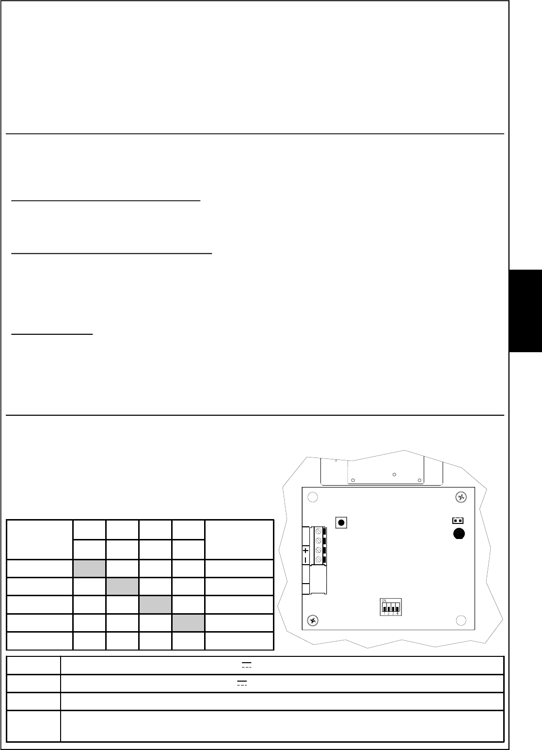
General Description
The system is made by a Transmitter and a Receiver which must be installed as a couple,
choosing the same working frequency among the 5 available, in both units (tx and rx) ,
through SW1 (4 dip-switch module) on board.
Compatibility with existing models
In case of replacement, choose the same frequency on the beam to be replaced (F1 by F1, F3 by F3
etc.). In order to identify the corresponding frequency, use the chart “BEAMS CHANNELS”
Filter of selection and compensation
Any receiver is equipped with a selection filter choosing only the frequency of its channel and rejecting
the others, thus not making possible the elusion of the beam in case of use of a false transmitter.
Special self-adjusting and signal-elaboration circuits have been used in the receiver for automatic
compensation of temperature variations.
Detection Area
The shape of the irradiation area is very well defined and this allows a higher possibility of detection
and a reduction of false alarms risk.
These beams are manufactured exclusively with solid-state components and are tropicalyzed in
order to obtain a very good seal against weather conditions.
Transmitter
The transmitter is made of a planar microwave emitting a narrow and directional higly-stable low
power beam.
A 4-dip-switch for setting working frequency is on board.
Check that the transmitter working frequency set is the
same as in the receiver coupled
-supplying negative 12 V
+supplying positive 12 V
T T n.c. output for protection agaist detector opening
S1 closed
open
supplying Led enabled
supplying Led disabled
BM M
CHANNELS
DIP DIP DIP DIP BM Q PLUS
CHANNELS
1 2 3 4
F1 ON OFFOFFOFF GOLD
F2 OFF ON OFFOFF BLUE
F3 OFFOFF ON OFF SILVER
F4 OFFOFFOFF ON YELLOW
F5 OFFOFFOFFOFF -
E
N
G
- 38 -
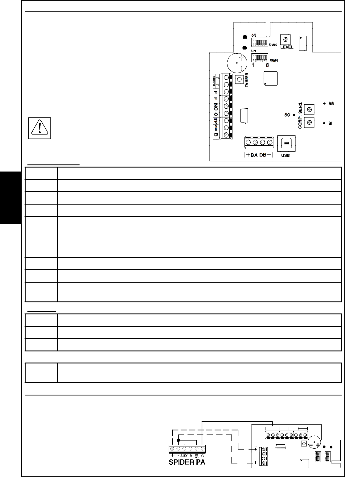
BM60HP - BM120HP - BM200HP Wiring systems receiver
The Receiver is made of a high sensitivity electronic circuit
coupled with the antenna; it captivates the signal transmitted
on its own channel and measures its intensity. Special
signal processing techniques enable compensating the
variations of the surrounding environment and
minimising the effect of any disturbances produced
by small animals or birds.animals or birds.
The electronic board contains two consoles with 8 dip-
switches; the first 4 dips, of console SW2, are for the
setting of the work frequency.
Check that the working frequency of the
receiver is the same as set in the transmitter
coupled.
AUX Input
The AUX input allows detecting the opening or not of an auxiliary detector connected to this
clamp. This input is not balanced, but is normally
closed with negative reference.
TAMPER
SW1
SW2
TP
1
B
FF
TAMPER
T T CNC AUX
DB
DA
LED
ROSSO
LED
VERDE
8
ON
ON
CONNECTION EXAMPLE
Terminal board
-negative power supply 12 V
DA-DB serial port for serial connection in RS485
+positive power supply 12 V
T T output normally closed for protection against detector opening
F
F
Disqualification signal relay; normally closed during the quiet status.
This relay opens in case the signal from the Transmitter is not received for 30
seconds.
C / NC alarm relay exchange normally closed
TP Test Point positive output for the displaying of the received signal
AUX NC input for the connection of an outdoor detector
Bpositive input: 12 V for stand-by; giving a positive to this clamp, the alarm relay
locks in quiet status
Trimmer
LEVEL trimmer for the adjustment of the received signal
SENS. trimmer for the sensitivity adjustment; increases by turning clockwise
COMP. trimmer for the compensation adjustment; increases by turning anti-clockwise
Connection
USB USB connector for PC and programming software connections
E
N
G
RED
LED
GREEN
LED
- 39 -
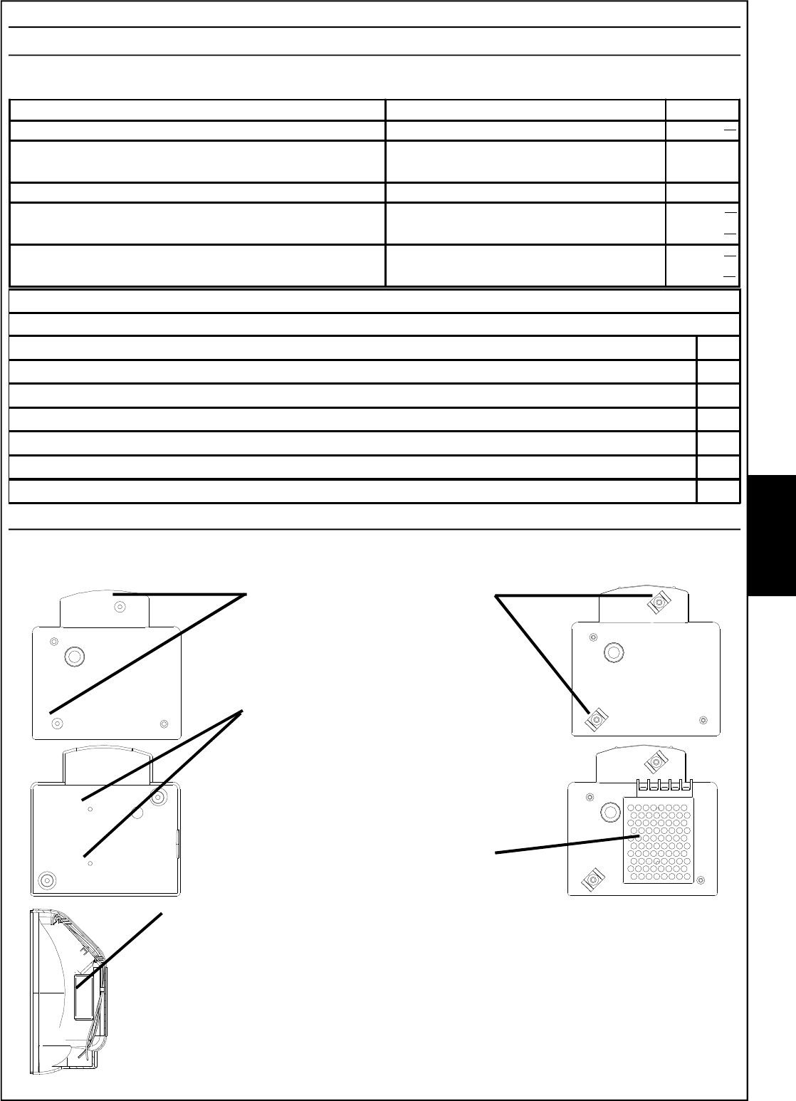
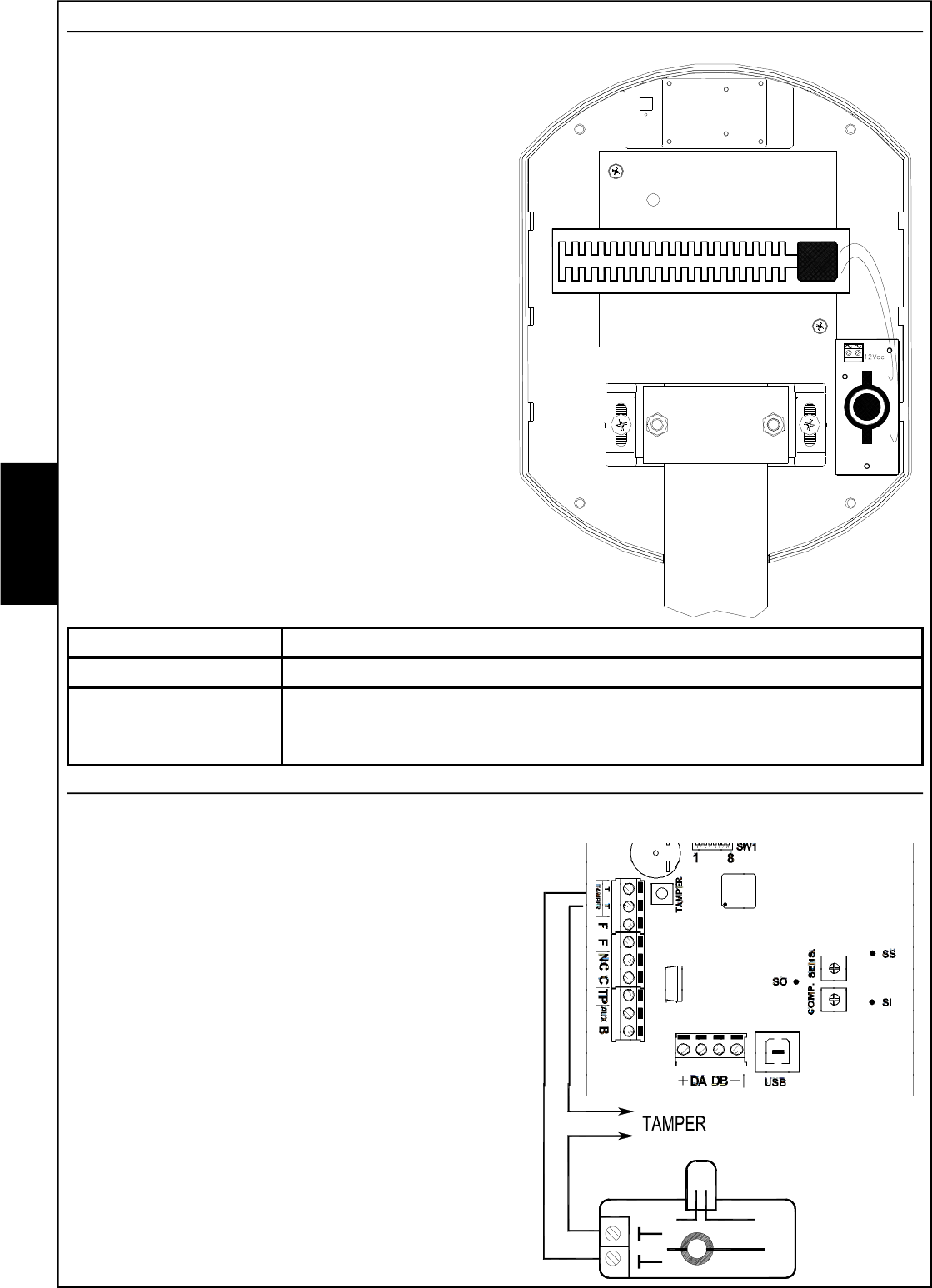
Extra power supply unit for BM 60-120-200 HPVAC
Tropicalised power supply unit
The power supply unit is a 15W switch with an output voltage of 13.8V and a maximum current of 1
A.
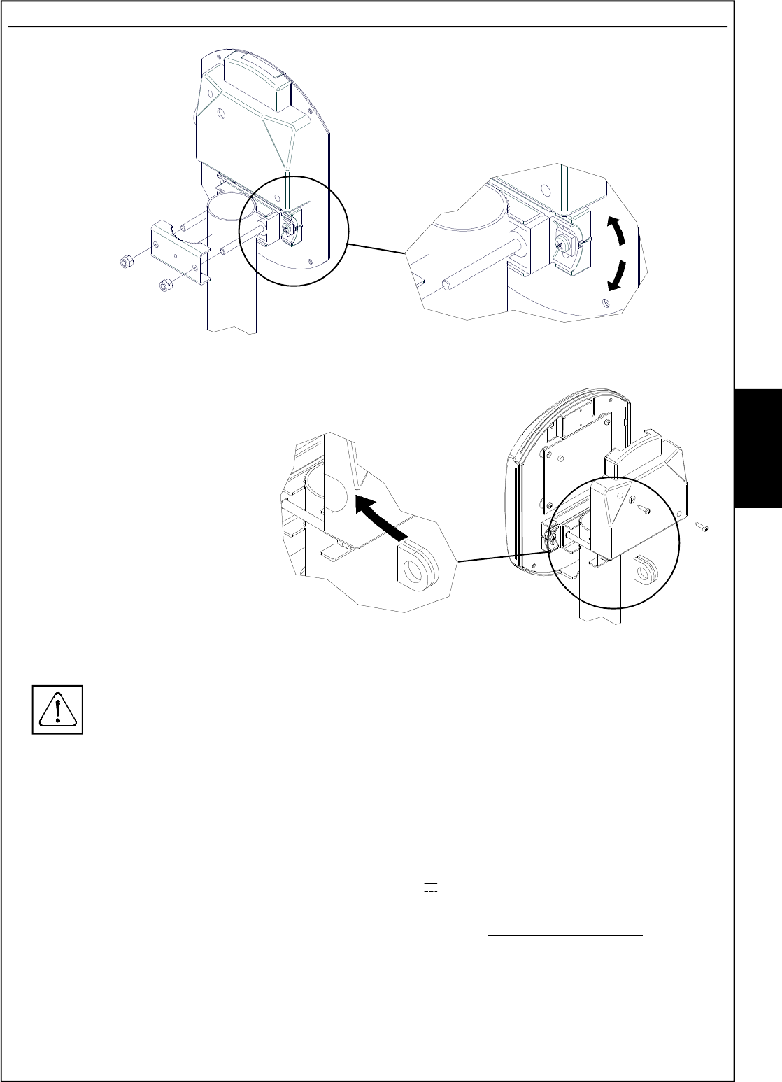
Fasten the two clips supplied to
the two turrets, with the Ø 4.2 x
6.5 mm self-threading screws
supplied.
Using the marks on the inside of
the cover, make two 3 mm holes
to fasten the power supply unit in
place.
Fasten the power supply unit in
place using the two M3 x 4 screws
supplied
The 12 V 0.8 Ah Y08A12 buffer battery (optional) (article code 1143118) (to be
fastened in place using the clip supplied) is housed on the lower part of the
back cover of the barrier, which must never exceed the dimensions of 65 mm
high, 96 mm wide and 25 mm deep.
To connect the Y08A12 battery, use the wire supplied, with the protective fuse
F 1A L250V and the connector for release if the cover comes open. If you use
a different battery with the same characteristics, it is necessary to eliminate the
connector in order to connect it to the power supply unit in the most appropriate
way.
Installation
Both in the receiver and the transmitter, the power supply unit must be fastened to the protective
cover of the electronic board:
E
N
G
Mains power supply 100-240V~ (+/-10%) 50/60Hz
Voltage Rated supply voltage 13,8 V
Max. current absorbed from the mains 115V~
230V~ 100 mA
Maximum current available Power supply unit 1A
Output voltage at 110-230V - 10% empty
With maximum load
13,8 V
13,6 V
Output voltage at 110-230V + 10% empty
With maximum load
13,8 V
13,6 V
ACCESSORIES SUPPLIED
Clips 2
Cable locking clips 4.5 mm wide - 120 mm long 2
Wire locking clips 2.5 mm wide - 98 mm long 2
Battery fastening 7.5 mm wide - 250 mm long 1
Clip screws ø 4.2 - 6.5 mm long 2
Power supply unit screws M3 x 4 2
Buffer battery connection wire with F 1 Amp L250V fuse 1
- 40 -
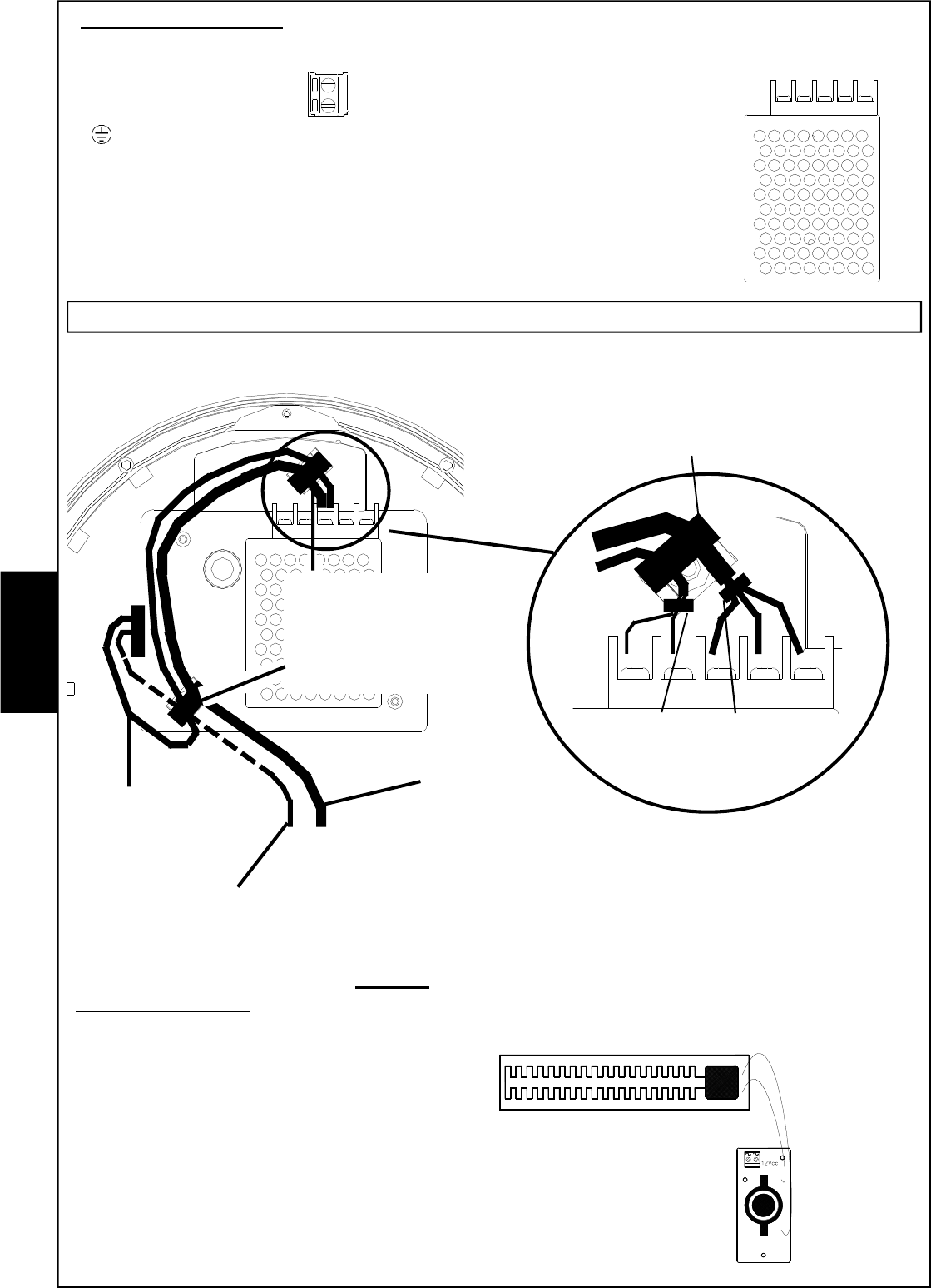
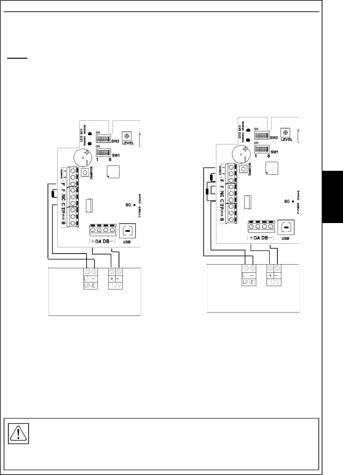
Insert an omnipolar network switch in the electric installation of the building.
Connect the input of the mains voltage to the terminals marked L N (AC) and
the + and the - of the barrier board to those marked V+ e V- respectively.
The input for the mains power supply must be connected with double insulation wires
The 3 wires for the 230 V ~ mains power supply
and the 2 wires for the 13.8 V power supply must
fastened securely together with their own clip
(as shown in the figure) to stop them coming
into contact with sensitive parts of he barrier
if they come loose from the terminal.
Wire clip
(use the two small ones
supplied)
To guarantee electric safety, the wires must be
fastened in place using the clip directly on the
protective sheath
External connections
The power supply unit must be connected as follows:
(1) V+
(2) V-
(3) Earth
(4) Neutral 220V ~ N
(5) Live 220V ~F
To be connected to the entrance of
the TX and RX board, respecting the
polarities
1 2 3 4 5
Power supply
12 V board
Power supply
220 V ~ main
Fasten the sheath of the
wires in the set points,
using the bigger clips
supplied.
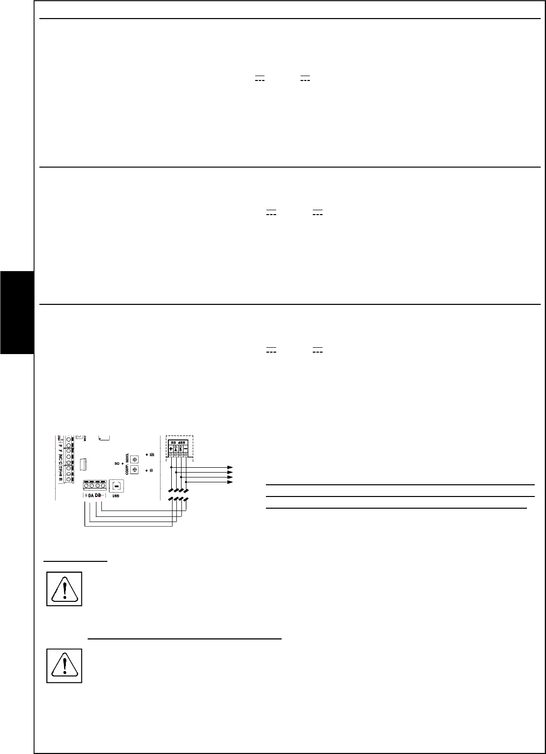
Signals to the central control unit
In the case of serial connections, in
addition to the DA and DB clips, it is
necessary to connect the power
supply negative from the power
supply unit to the central control unit,
and we recommend the use of 0.5mm²
section sheathed wires.
In the BM 60 - 120 and 200 HPVAC barriers it is possible to feed
the TERM 1 module (Optional) (Article code 1143102) directly with
the power supply unit on the barrier, inserting a protective fuse
F500mAL250V.
E
N
G
-
+
IN ALIM.
BATTERIA
- 41 -
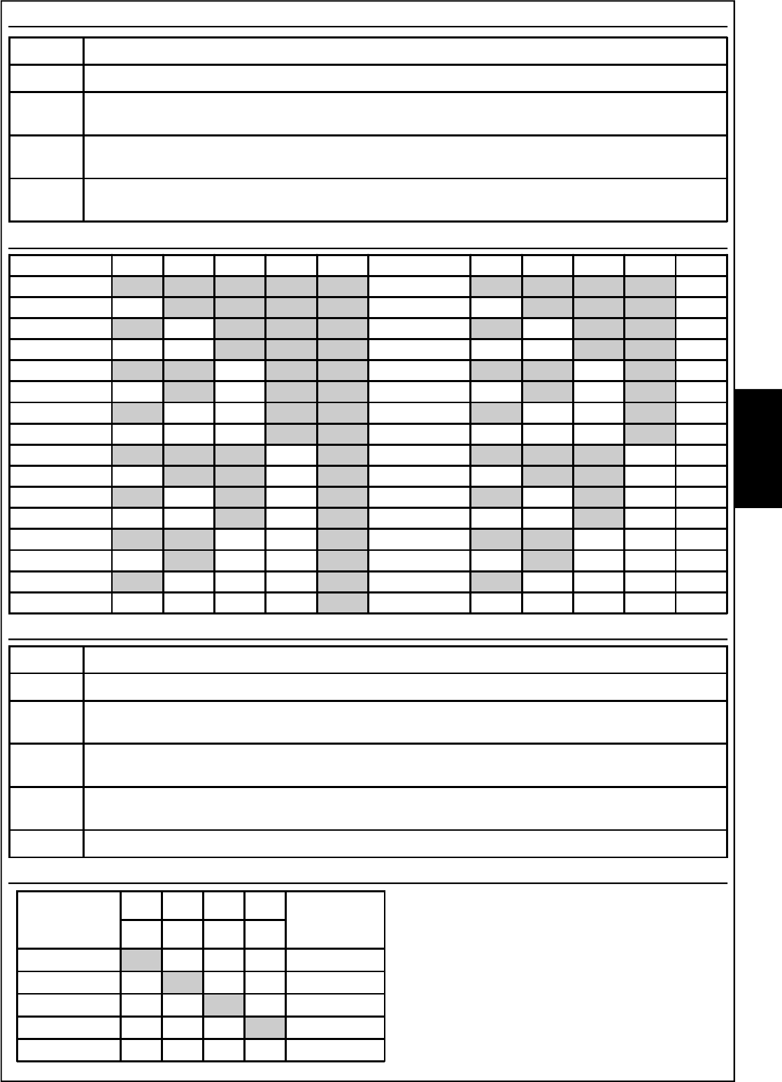
DIP SWITCH - SW1
DIP Associated function
1 .. 5 Selection serial addresses of the barrier - see addresses table
6ON - Compensation activated
OFF - Compensation deactivated
7ON - enables recording of the events even with lock engaged (B)
OFF - events recording disabled with lock engaged(B)
8ON -Active AUX input, the barrier reads the input
OFF - Excluded AUX input, the barrier does not consider the input
DIP Associated function
1 .. 4 Microwave frequency selection - see frequencies table
5ON - Enabled microwave signal quality green LED
OFF - Disabled microwave signal quality green LED
6ON - Enabled alarm signal buzzer
OFF - Disabled alarm signal buzzer
7ON - Enabled alarm signal red LED
OFF - Disabled alarm signal red LED
8Unused, for future uses.
DIP SWITCH - SW2
Detector DIP1DIP2DIP3 DIP4DIP5 Detector DIP1DIP2 DIP3DIP4DIP5
1ON ON ON ON ON 17 ON ON ON ON OFF
2OFF ON ON ON ON 18 OFF ON ON ON OFF
3ON OFF ON ON ON 19 ON OFF ON ON OFF
4OFF OFF ON ON ON 20 OFF OFF ON ON OFF
5ON ON OFF ON ON 21 ON ON OFF ON OFF
6OFF ON OFF ON ON 22 OFF ON OFF ON OFF
7ON OFF OFF ON ON 23 ON OFF OFF ON OFF
8OFF OFF OFF ON ON 24 OFF OFF OFF ON OFF
9ON ON ON OFF ON 25 ON ON ON OFF OFF
10 OFF ON ON OFF ON 26 OFF ON ON OFF OFF
11 ON OFF ON OFF ON 27 ON OFF ON OFF OFF
12 OFF OFF ON OFF ON 28 OFF OFF ON OFF OFF
13 ON ON OFF OFF ON 29 ON ON OFF OFF OFF
14 OFF ON OFF OFF ON 30 OFF ON OFF OFF OFF
15 ON OFF OFF OFF ON 31 ON OFF OFF OFF OFF
16 OFF OFF OFF OFF ON 32 OFF OFF OFF OFF OFF
Serial addresses table - SW1
BM HP
BARRIER
CHANNELS
DIP DIP DIP DIP OLD
BARRIER
CHANNELS
1 2 3 4
F1 ON OFFOFFOFF GOLD
F2 OFF ON OFFOFF BLUE
F3 OFFOFF ON OFF SILVER
F4 OFFOFFOFF ON YELLOW
F5 OFFOFFOFFOFF -
Frequencies Table - SW2
E
N
G
- 42 -
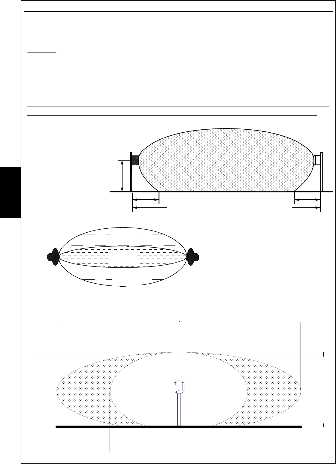
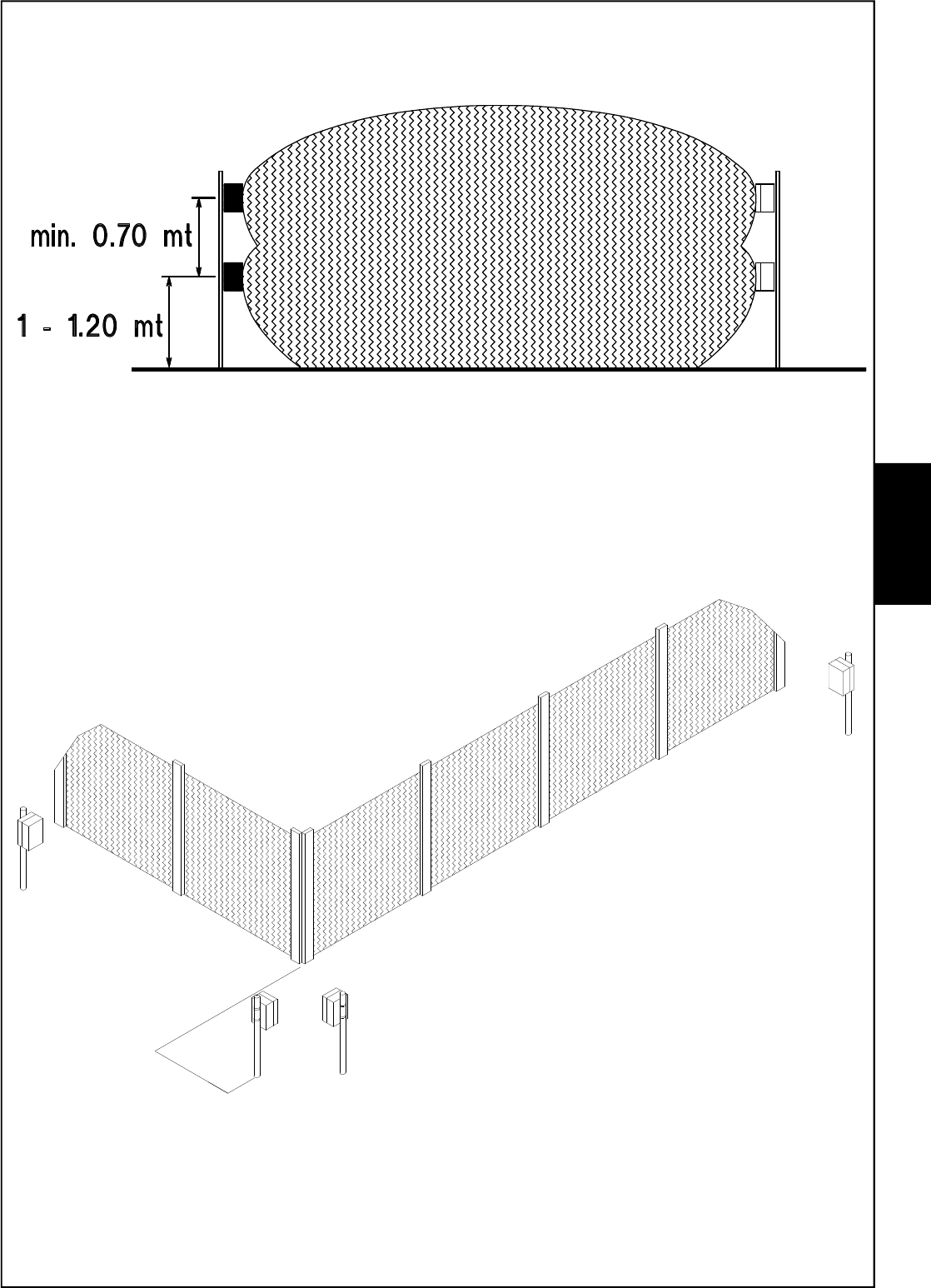
1 - 1,2 mt
3 meters 3 meters
The sensitive zone shown in the drawings is to
be taken into consideration, as a big target.
Overpassing this area might cause the
same perturbations as a small body
passing the alarm area, that’s to say might
cause false alarms.
BM60HP
6,5 meters
BM120HP
10 meters
BM200HP
16 meters
BM60HP
2 meters
BM120HP-BM200HP
3 meters
BM60HP 1,2 meters
BM120HP 3 meters
BM200HP 4 meters
Alarm zone
Sensitive zone Sensitive zone
Description of working
The two units (transmitter: TX and receiver: RX) must be positioned facing each other at the two
ends of the distance to protect. Be aware that the nature of the ground underneath, or special
weather conditions might affect the real range.
Working
The transmitter emits a modulated microwave signal (10,525 GHz), which is received by the
receiver and whose amplitude is compared with the programmed alarm threshold.
When an intruder crosses the microwave area, it causes a signal-intensity decrease under a
minimum level fixed; the receiver shows the alarm condition, lighting up a red Led indicator and
opening the contat of the alarm relay.
If the signal of the transmitter is not received for over 30 seconds, the alarm relay could go back
to quiet condition and the negative to terminal D (disqualification) fails until signal restoring.
For this reason, in the hard-wired system, it is suggested to make the connection described
in the chapter concerning
disqualification.
The drawings identify the
natural shadow areas in
the immediate
sorroundings of the
two units, which extend
for about 3 meters, in a
typical installation at 1 - 1,2 m height.
Note: the diagrams of the patterns shown in the drawings are an indication and a guide
during installation. They do not represent the real radiation diagram of the antennas as
they may be subject to variations due to environmental context.
sensitive
zone
sensitive
zone
alarme
zone
BM60HP : max 60 meters
BM120HP : max 120 meters
BM200HP : max 200 meters
E
N
G
- 43 -
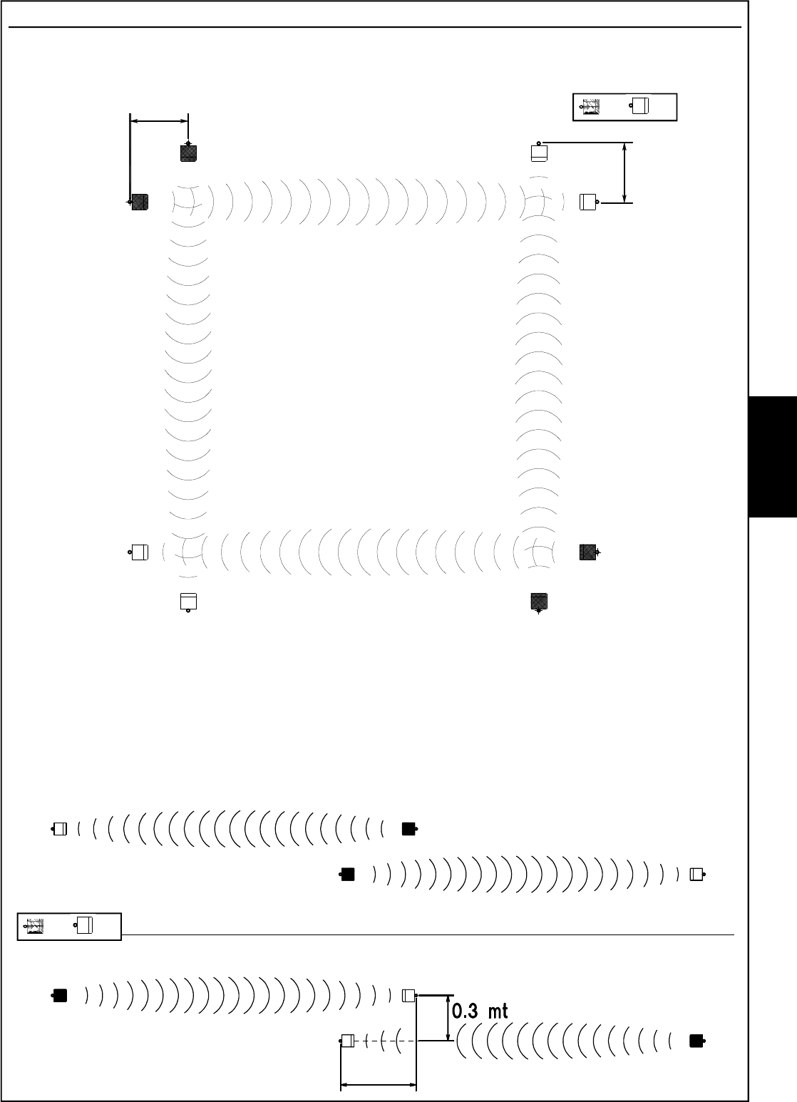
Positioning of the beams
For a correct installation of the system, choose carefully the positioning of the two units, according
to following advice:
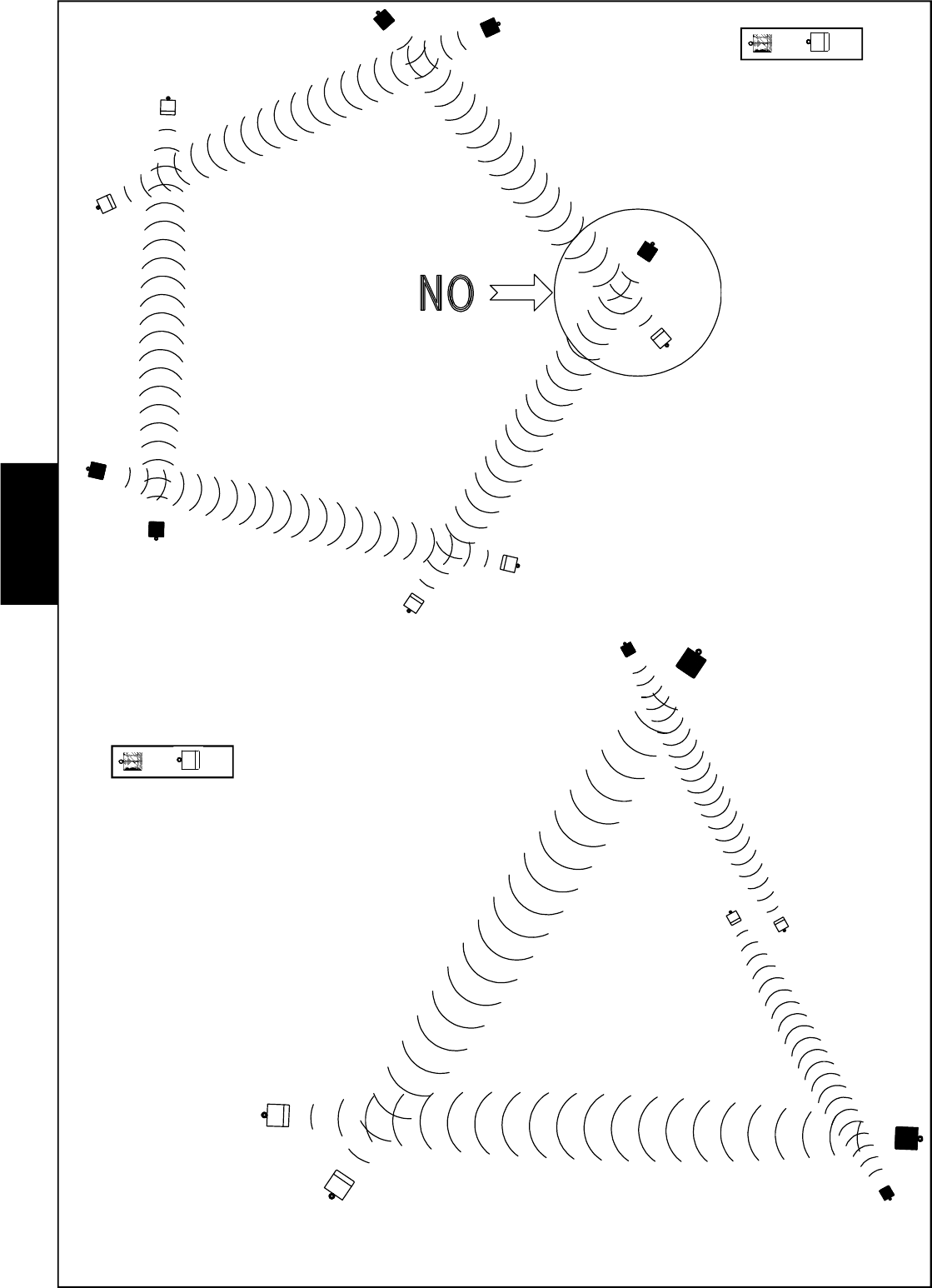
Drawings identify the correct positioning of transmitters and receivers, in order to eliminate any
possible shadow area.
The drawings here below show how one or more couples of beams have to be positioned for
reaching the distance required.
BE CAREFUL: only elements with different frequencies (F1, F2, F3, F4, F5) and of the
same type (TX/TX or RX/RX) can be installed in proximity one to the other; in order to
avoid interferences between transmitters and receivers belonging to different couples.
The typical installation of
BM HP system consists in
sorrounding the area to be
protected by use of more
beams couples in order to
obtain a proper perimetric
fence
3 mt
3 mt
TX RX
TX RX
E
N
G
6 mt
- 44 -
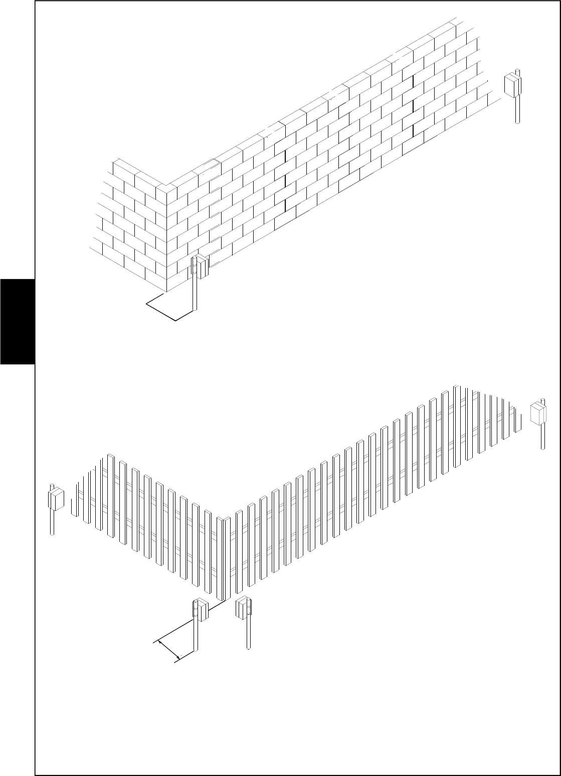
If, in a perimetric installation, the
beams cross the patterns, they
must always be installed in
pair (2, 4, 6 etc.)
It is absolutely
necessary to
avoid installing a
transmitter near a
receiver belonging
to another couple
TX RX
TX RX
E
N
G
- 45 -
In order to extend the height of the protection, two couples of beams
can be installed as shown in the picture. In this case, it is
suggested to use couples of beams having
close working frequency (two couples
with frequency F1 and F2 or F3 and
F4)
BM60HP : 1 meter
BM120HP : 10 meters
BM200MHP : 10 meters
If the fence is made of bushes or metal fences
subject to possible movement, the minimum
distance must be 1 meter for BM60HP
and 10 meters for BM120HP and
BM200HP.
E
N
G
- 46 -
BM60HP : 1 meter
BM120HP : 5 meters
BM200HP : 5 meters
If a couple must be installed
near a building or a fix fence, a
minimum distance of 1 meter for
BM60HP and 5 meters for BM120HP and
BM200HP must be kept.
This is required in order to avoid false alarms
caused by reflection of microwave
beam.
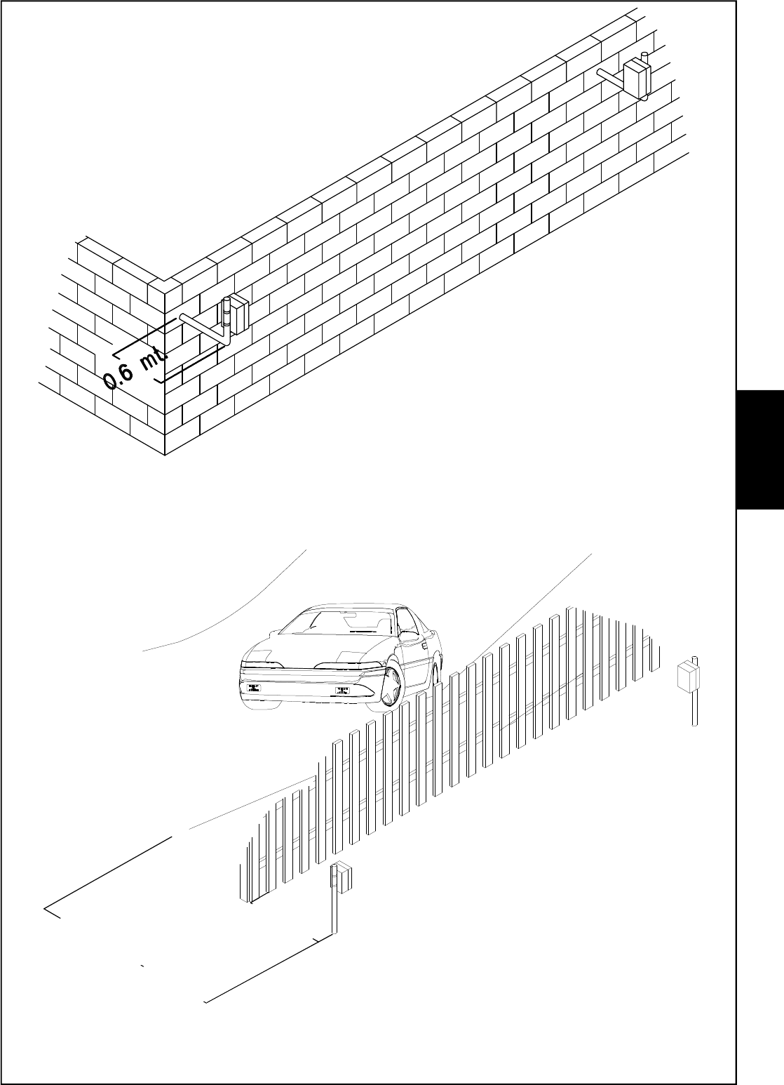
BM60HP : 0,6 meters
BM120HP : 2 meters
BM200HP : 2 meters
A corridor large not less than 0,6 meters for BM60HP
and not less than 2 meters for BM120HP and
BM200HP, must be left free from obstacles
between transmitter and receiver; a clear
visual must always be granted in this
area
The suggested height for the installation is
between 1 and 1,2 meters.
E
N
G
- 47 -
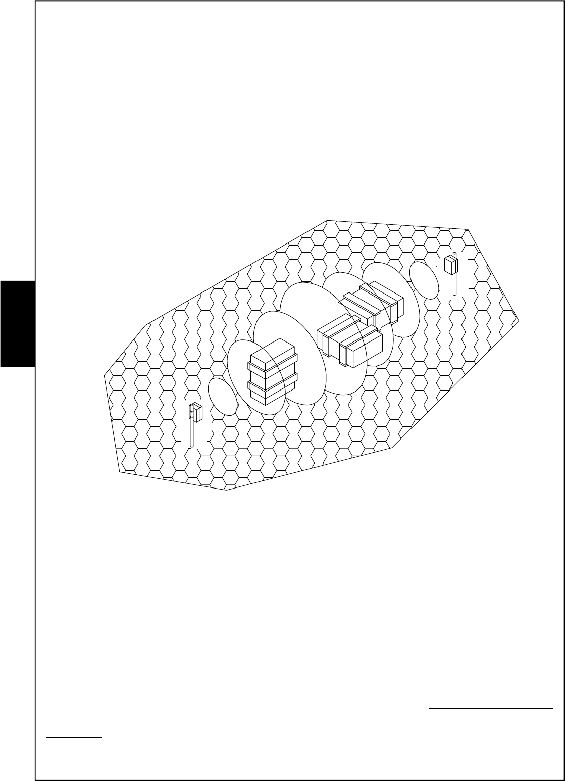
It is possible to install the system BM60HP also to protect
walls. In this case, the system of installation shown
in the drawing can be used, in order to avoid
false alarms caused by cats or birds. In
this case also, the height from
ground must be between 1 and
1,2 meters.
Because of ground
characteristics, it may
happen to have a very high
sensitivity in the centre of the
protected area and near the ground,
because of special reflection of the ray.
BM60HP : 4 meters
BM120HP : 10 meters
BM200HP : 10 meters
It is also possible
to install the system
BM HP along a transited
street with transit; in this case,
it is necessary to keep a minimum
distance of 4 meters (for BM60HP)
or 10 meters (for BM120HP and
BM200HP) between the sight-line of the
couple and the area of transit of the cars.
In case a metal fence is placed between the
transit area and the area to be protected, detectors
must be kept at a minimum distance of 1 meter (for
BM60HP) or 5 meters (or BM120HP and BM200HP) from the
fence.
E
N
G
BM60HP :1 meters
BM120HP : 5 meters
BM200HP : 5 meters
- 48 -
•Should any pet be present and free in the installation area, it is suggested to carefully adjust
sensitivity, in order to avoid the risk of false alarms due to the passage of these small targets
in the areas which are very sensitive at the ground. To further decrease this risk, the height
of installation of the couple can be increased a little bit.
•Should trees or bushes affect the protection corridor because of the wind, false alarms
might occur. In the same way, if the system is installed near a hedge, this one must be
carefully attended to avoid darkening the protected area.
•High grass ad bushes decrease sensitivity at groud level.
•Any obstacle or important difference of level in the ground in the protected area, create
shadow-areas and very sensitive zones.
The BM HP system has a good tolerance against bad weather conditions and temperature
variations; nevertheless it is necessary to care for following situations:
•RAIN: strong rain only causes a decrease of signal power whilst water puddles may increase
sensitivity at ground level
•SNOW: snow fall does not affect beams sensitivity, but the system cannot work if it is entirely
covered by the snow; so take care in areas with frequent and abundant snow
•FOG: a very thick fog can decrease the signal for 1/3. Because of the limits of compensation
of the gain automatic control (C.A.G.) , it is suggested to install the beams couple at a
distance not exceeding 85% of max range,in the regions where a thick fog is frequent.
The temperature working concditions are between - 20°C and + 55°C; if the use is required in
areas where temperature goes lower than 0°C, it is necessary the permanent installation of the
heating kit, which requires an alternate current at 12 V for a consumption of 150 mA for any
element of the beam (see Kit TERM for installation of heating kit).
E
N
G
- 49 -
Advice for installation
•Use special care for the
cables entry, in order to avoid
moisture and rain penetrating
inside the box.
•For cable entry inside the
covers of board protection, use the
cable-loops given within (as shown in the
drawing)
•In the hard-wired system use anti-fire shielded cable (2 x 0,75 mm² + 8 x 0,22 mm²)
In the wireless system, connect the support pole to ground and use an additional
shield for the supplying cable 220 V ~ inside the pole, in order to create a double
isolation.
•Before installing the support poles in a definitve way, it is suggested to make a trail installation
in order to find out the best position of alignement for the best effective detection:
1Position the beams couple in the centre of a free area, respecting the minimum distances
for beams positioning and the installation height
2 Supply the transmitter and the receiver with two batteries and orientate TX and RX one
towards the other
3 Check the signal on TP and adjust it at 7,3 V .
4Move the two beams towards RIGHT/LEFT within 30 - 50 cm and Up/Downwards
checking the variations of signal of TP and identifying the signal max point.
5 Once identified the best position, fix the brackets.
•During positioning and adjusting of the Receiver, take care not to have big bodies inside the
sensitive zone, which will then be moved when the system is in use, such as lorries or cars;
the adjustment could be highly affected.
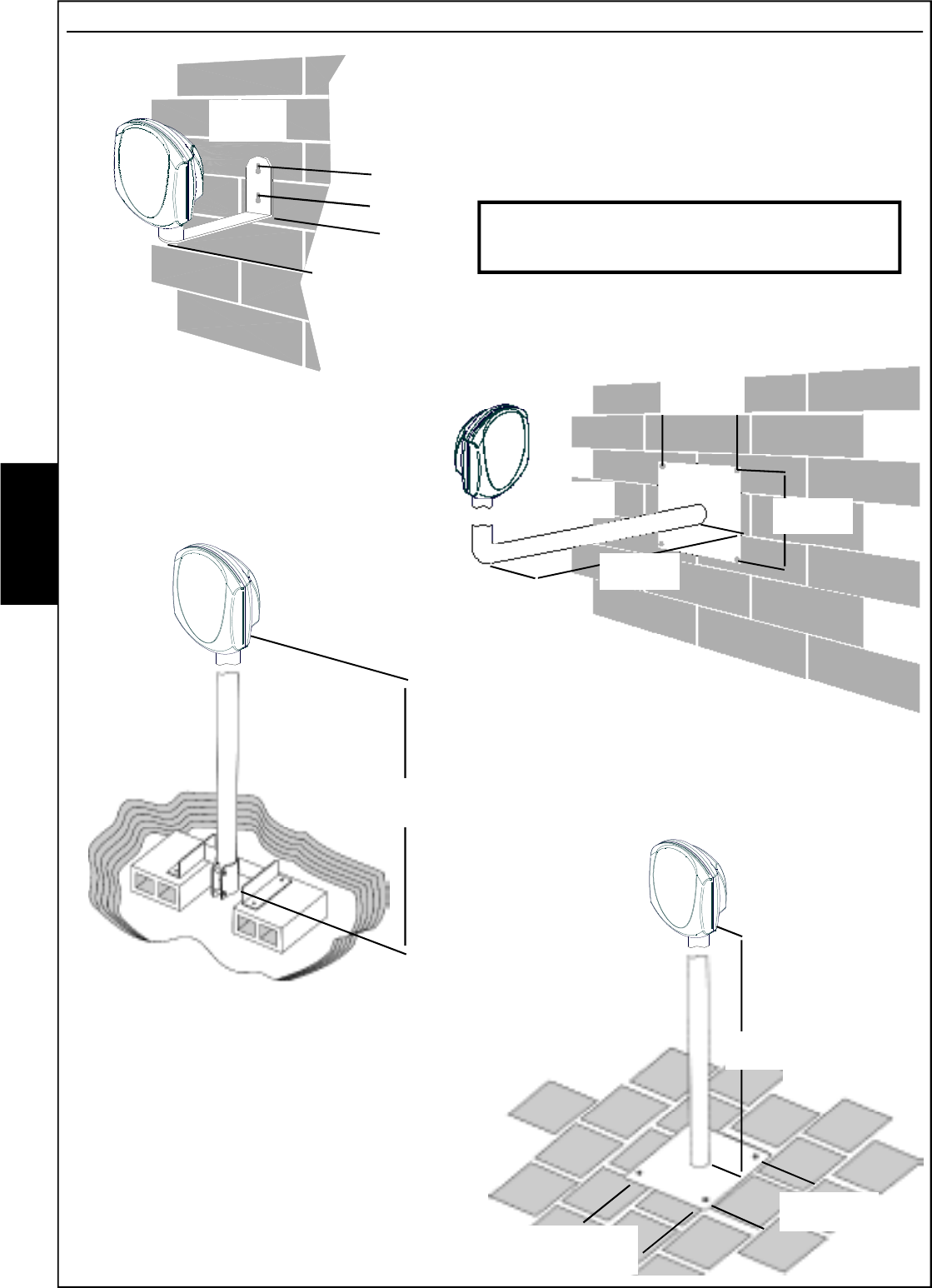
The fixing bracket
is pre-arranged
for the
installation
on a steel
pipe, whose
external
diameter is 40
millimeters
Thanks to the two slides on the sides of
the fixing bracket, it is possible to adjust
the inclination (max 5° upwards
and 5° downwards) in both
transmitter and
receiver.
Two
notches on
the slides indicate the
max inclination
E
N
G
- 50 -
Transmitter installation inside the wire system
1) Choose the position of the Transmitter, fix it at the wanted height and adjusted as precisely as
possible in the direction where the Receiver will be mounted.
2) Position the 4 dip-switches depending on the chosen work frequency.
3) Connect the power supply (from 11.5V to 15V ) and check the functioning of the Transmitter,
by switching on the red LED; by removing the bridge S1 (Led Off), the LED can be disabled to
decrease absorption.
4) Connect the TT clamps of the electronic board tamper to the tamper proof line of the control
unit.
Receiver installation inside the wire system - UNIVERSAL
1) Install the Receiver in the envisioned support point, at the same height as the Transmitter.
2) Position the 4 dip-switches depending on the chosen work frequency.
3) Connect the power supply (from 11.5V to 15V ) to the positive + and negative - clamps.
4) Upon commissioning, the LED and buzzer, if enabled, will flash for a stabilising time
5) Connect the C and N.C. alarm outputs and the "FF" disqualification signal output to the
detection line of the control unit and the electronic board tamper TT clamps to the tamper
proof line of the control unit.
Receiver installation inside the wire system - SERIAL
1) Install the Receiver in the envisioned support point, at the same height as the Transmitter.
2) Position the 4 dip-switches depending on the chosen work frequency.
3) Connect the power supply (from 11.5V to 15V ) to the positive + and negative - clamps.
4) Upon commissioning, the LED and buzzer, if enabled, will flash for a stabilising time
5) Connect the DA and DB serial communication clamps on the barrier, to the respective on
the satellite. The alarm signals, tampering, fault and all technical signals will be reported
using this connection.
• It is possible to connect on the same serial port RS485, up
to 32 barriers.
•For connection of serial communication terminals DA
and DB only, shielded cables of 0.5 mm² are suggested,
whilst the section of the supplying cables (+ and -) of the
devices connected to the serial has to be chosen by the
installer according to the system and to his experience
•The total length of the connection cable can be 600 meters
and must be subdivided for all connected electronic boards.
Addressing
Should installation envision more points, the installed barriers must be addressed using
the dip-switch, on the electronic board of the same barriers.
The numbering of the barriers must be progressive and there cannot be more peripherals
with the same serial address.
Main warning for the wiring system
We recommend reaching the two units by means of flexible and water proof plastic
piping and carry out connections using shielded conductors.
The choice of section of the conductors to use for the connections must be carried out
depending on the distance from the power supply source, to guarantee a continuous
minimum voltage of 12 Vol, on both units. Malfunctioning may occur should the power
supply voltage drop below such value.
Towards the
other barriers
E
N
G
- 51 -
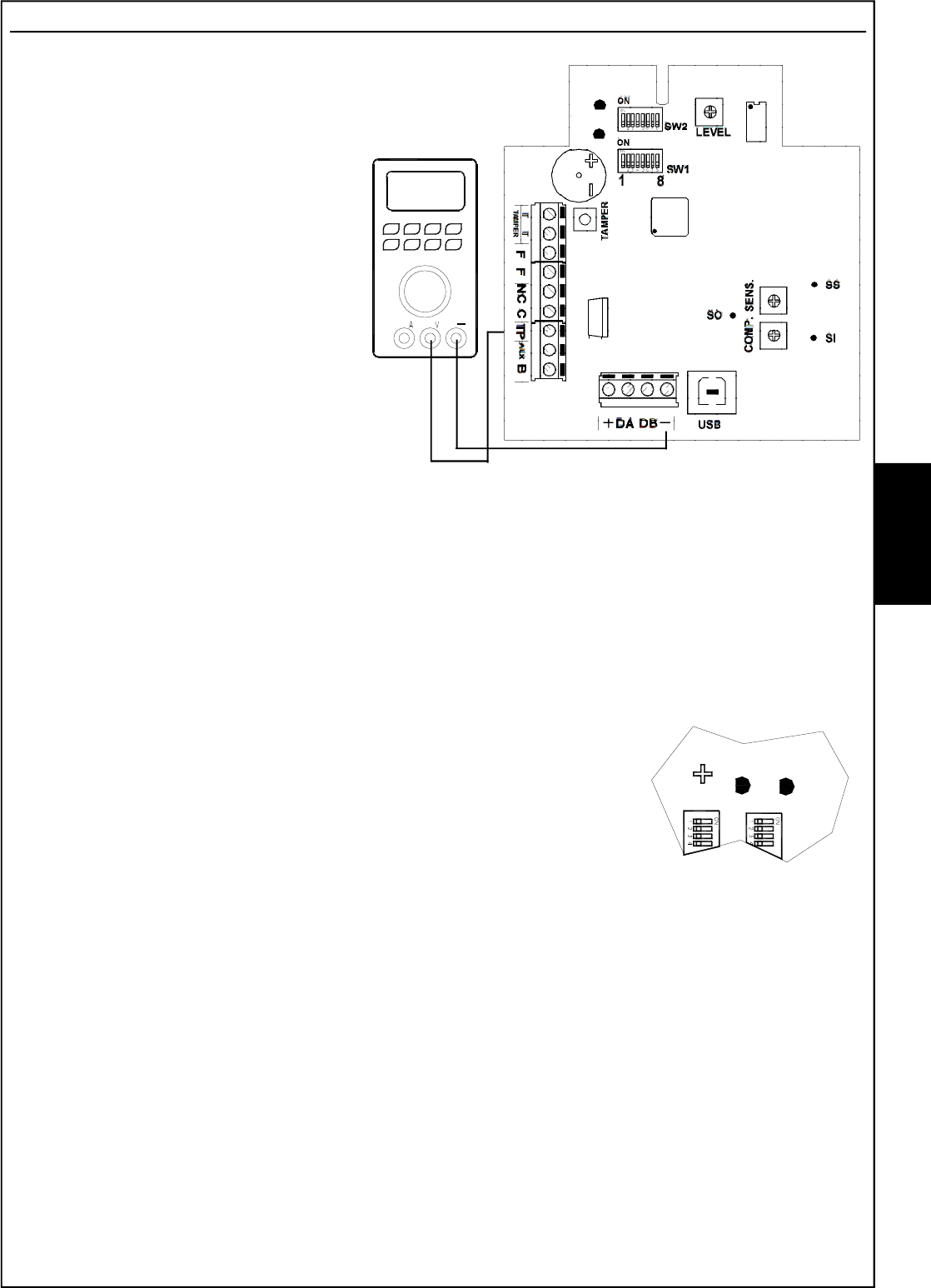
Adjustments
1)Orientate at sight the device in the
direction of the transmitter and
connect a voltmeter betwen the ne-
gative (-) and TP terminal (Test
Point) on board
2) Orientate the device in horizontal
way, looking for the position giving
the max reading; in case it is over
7,3 Volt tthe signal level must be
reduced by use of LEVEL trimmer,
in such a way as to bring the signal
to the best point of working, that’s
to say 7,3 Volt
•It is possible to have a high value
also with receiver not aligned to
transmitter; in this case it could be
a reflection of the beam
transmitted, which must most be
taken into consideration.
•In case the signal does not reach 6,8 V having LEVEL trimmer at max, move the device in
vertical way within a limit of 10-20 cm.
•Shouldn’t it be possible to reach the min. value, it will be necessary to decrease the distance
between receiver and transmitter or look for a better alignement position
3)Check the quality of the signal received, keeping in mind that in absence of seeming
movements inside the protected area:
•Green Led on fix: there is no signal noise
•Green Led quick or slow flashing: the signal noise is low but
is anyway detected by the beam
•Green Led slow flashing (off for about 1 second) , the signal noise
is more important and it is near to the intervention threshold of the beam
In order to have a more precise indication on the quantity of noise and to have the possibility
of making adjustments according to the environmental context, we suggest to use the software
HPSOFT
4) after all tests, LEDs can be deactivated in order to reduce the consumption of the receiver
Note: Thanks to the digital trimmer, the barrier has the possibility of self-calibrating the signal
level (LEVEL) and to compensate the environmental variations, guaranteeing the stability of
the signal. Fog, snow, gradual variations of the reflecting surface will be automatically
compensated by the barrier, both in positive and in negative, within certain values. Should
the requested variation be above that tolerated by the system, the disqualification signal
(FF) will be had.
7,3 Volt
LED
ROSSO
LED
VERDE
ON
ON
E
N
G
GREEN
LED
RED
LED
RED
LED
GREEN
LED
- 52 -
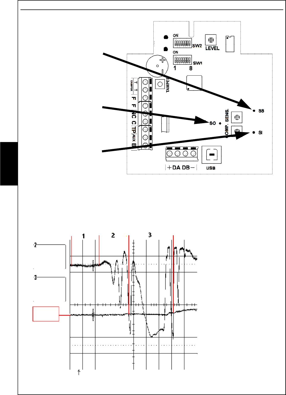
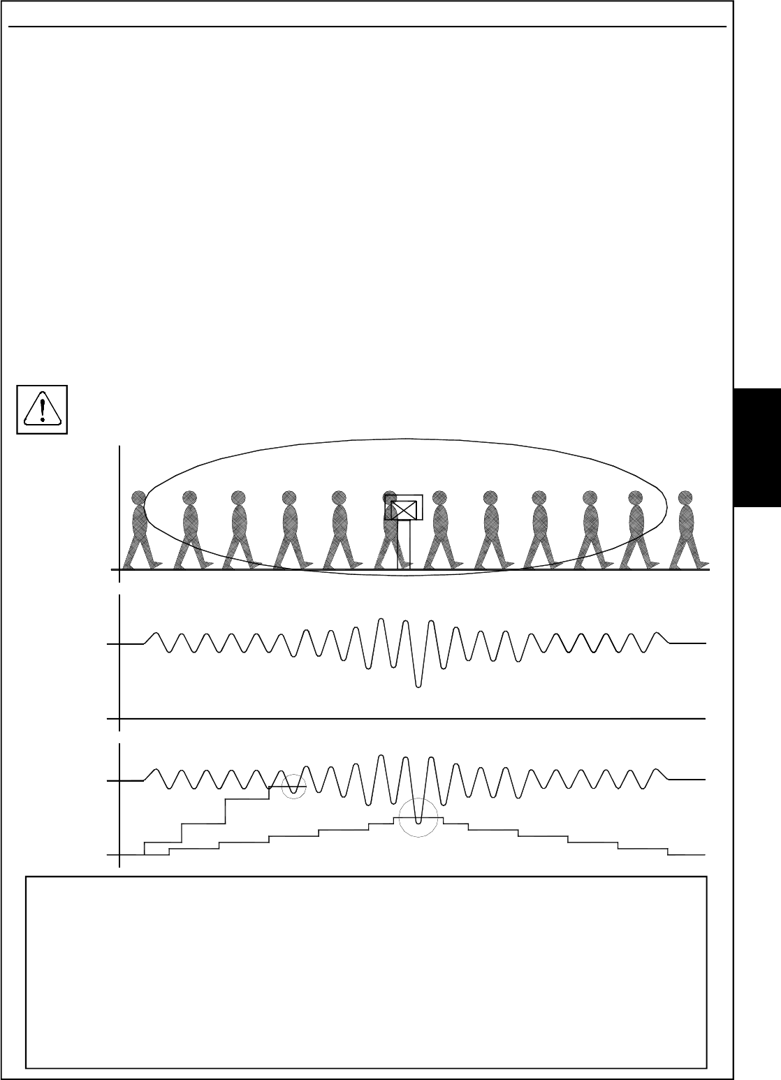
Measurements of the signal by oscilloscope
In the drawing below, the points where to connect
the oscilloscope are shown:
Point B shows the quality
of the signal received
In the graphic here below the wave shapes concerning the signal quality are shown:
1- the beam is in quiet condition and there is no passage of people or any perturbation due to
moving objects, the level is fix . Check that the quiet condition is as described.
2- the beam is disturbed or we are crossing a sensitive area (partial darkening)
3- the beam has been darkened and there is an alarm situation
Point C shows the alarm
threshold (trimmer sens.).
In this case the sensitivity
is adjusted at the half
C
B
.2 s
0.5 V
.2 s
0.5 V
.2 s
2 .1 V DC x
10
3 .1 V DC x
10
0 V ž
Sensitivity
range
Punto A
(ss)
Indicates the range
of the received
signal
Punto C
(SO)
Indicates the alarm
threshold
Punto B
(SI)
Indicates the quality
of the received
signal
E
N
G
GREEN
LED
RED
LED
- 53 -
Sensitivity Adjustment
1) Turn the SENS trimmer anti-clockwise in the minimum sensitivity position and carry out a
test by walking in the central point of the covered zone (point with lower system sensitivity)
and check the behaviour of the green LED.
2) If required, progressively increase sensitivity until the wanted reply degree is obtained.
3) 3) After each sensitivity adjustment, wait for approx. 20 seconds for all signals to be set and,
therefore, carry out a new test.
Attention: an excessive sensitivity can cause unwanted alarms in critical conditions (intense rain,
snow, etc.).
4) 4) A special compensation circuit has been included in the BMHP system, adjustable by
means of the COMP trimmer (turning it clockwise increases compensation); this circuit
records the disturbances produced within the microwave field when the target is nearing or
moving away, transversally at lobe, and automatically increases the sensitivity of the Receiver
to facilitate detection when the target crosses the central line of the lobe. The compensation
circuit can be completely excluded using DIP6=OFF of SW1. An excessive compensation
can cause an unwanted alarm of the barrier when objects move near the lobe.
If wanting the complete management of the adjustments, using the software (mod.
HPSOFT), the trimmers "SENS" and "COMP" and DIP6=ON must be set halfway
CAUTION
(BM120HP and BM200HP ONLY)
Due to larger pattern and to compensation circuit, BM HP beams are more sensitive to
perturbations caused by moving objects in the areas near the corridor protected.
Consequently, the security distance to be kept in the installation, especially in respect to
the transit of vehicles, trains, or presence of big trees or bushes, must be increased. In the
special case of a street with vehicles transit, parallel to the protected area, it is suggested
to keep a minimum security distance of 10 meters.
Signal
Signal
Alarm
thresold
ALARM
Extreme Compensation
ALARM
Correct Compensation
Alarm
thresold
E
N
G
- 54 -
Kit TERM (optional) Resistence fo inside heating
•For installation in an indoor or outdoor place where
temperature can go lower than 0°C, it is
necessary to use the heating kit Term 1 in
both Receiver ad Transmitter. This has to
be done in order to avoid formation of
condensation which might affect the good
working of the electronic circuit.
•The optional heating kit, is made of a circuit
where an electromechanical thermostat, a
heating resistence and a terminal board for
connection to supplying, are placed.
•Supplying must be given by means of an
external trasnformer with output at alterna-
te 12V ; the consumption of any heating
resistence is 150 mA at the tension of alter-
nate 12 V.
•The thermostate intervention occurs taking
off supplying to the resistence when the tempe-
rature of 30° C is reached inside the box.
Kit AMP (optional) Anti-removal
The anti-removal kit AMP is made of two bulbs,
whose function is sending an alarm in case of
tampering or removal of the beam from its support.
This kit must be positioned in such a way that one of
the bulbs is installed in vertical position compared
to the device and the other one in horizontal position
as shown in the picture.
This system allows a complete protection against any
attempt of :
- removal of the beam from the support
- removal of the supports from fixing points
The horizontal bulb must be positioned in such a way
that the contact opens as soon as there is an attempt
of moving the beam.
Before connecting the tamper line to the control panel,
check that the contact of single bulbs as well as
tamper line is closed .
Supplying: alternate 12 V
Consumption: 150 mA max
Transformer: input: 220 V ~
output: 12 V ~
for 4 couples of beams: 20 W power
Example: RX BEAM
E
N
G
- 55 -
Disqualification (Important warning)
In order to prevent and signal misalignments caused with the system disarmed or by obstacles
interposed within the action beam of the barriers, for installations envisioning the UNIVERSAL
connection, it is essential to connect the disqualification output (FF clamps) in series to the alarm
relay exchange.
NOTE
The FF output supplies a normally closed relay exchange that opens when the signal level
drops below a minimum level for more than 30 seconds.
In the examples below, the control unit will signal the open zone, both in alarm and in
disqualification.
SINGLE BALANCING
CONNECTION
Balancing
resistance
DOUBLE BALANCING
CONNECTION
Balancing
resistances
E
N
G
The power supply must come from very low safety voltage circuit with the characteristics
of a limited power source protected by a fuse.
INSTALLATION AND MAINTENANCE MUST BE EXECUTED BY QUALIFIED
PERSONNEL
- 56 -
E
N
G
SB60
Optional Brackets
SB120
SB20
SB130
60 cm
14 cm
14 cm
130 cm
Optional bracket mod. SB60 can be used with
BM60HP
The bracket mod. SB60 has a base
rectangular 14x18 cm wheelbase of fixing
holes in the wall of 11x15 cm.
The optional bracket mod. SB20 and mod.
SB60 can be used for installation to the wall
The bracket mod. SB20 has a wheelbase
of fixing holes in the wall of 4 cm
Optional brackets mod. SB120 and mod.
SB130 can be used for installation to the floor
The bracket mod. SB120 has a square base
of side 18 cm with a wheelbase of fixing holes
in the floor 14 cm.
11 cm
4 cm
15 cm
120 cm
14 cm
14 cm
- 57 -
Special functions
Thanks to the software from PC HPSOFT, it is possible to make the best use of the potential of
digital technology.
HPSOFT allows, for each digital barrier:
-Check:
- microwave signals
- outputs status (alarm - disqualification - tamper)
- input status (AUX)
- barrier diagnostic (temperature - test point - compensation on/off - power supply)
- alarms history with over 3600 recordings complete of time and date
- customised archive by the installer
- synoptic barriers status (if connected in RS485 to satellite)
- signals recording archive per barrier
-Management:
- sensitivity adjustment
- compensation adjustment
- valid signal threshold adjustment
- customisation archive dedicated to "FALSE ALARMS"
- customisation archive dedicated to "ALARMS"
- signals recording
- select the detection method:
- traditional detection mode
- ALARMIDENTIFY detection mode
- upgrade firmware (not active in PSTN/GSM)
These functions are active with USB connection in local, meaning directly connected on to the
digital barrier receiver, or in USB on XSATHP satellite or PSTN/GSM telephone connection.
Once the management software is installed, it is necessary to create a numerical "New Code" in
"Clients Master" and define that it is BM 60 - 120 - 200 HP.
E
N
G
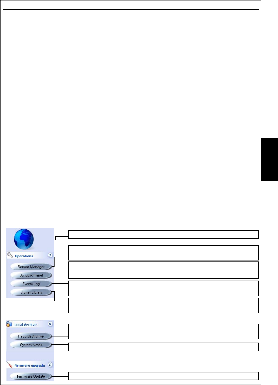
Return to initial screen
Activation of the USB/Telephone connection, for the displaying and
management of the barrier settings
Activation of the USB/Telephone connection, for the simultaneous
displaying of the barrier status
Activation of the USB/Telephone connection, for the displaying and
management of the barrier alarms history
Activation of the USB/Telephone connection for the customisation of
the signals library dedicated to the "Alarms/False Alarms"
Access to the local archive of the signals recordings carried out
manually by the installer
Access to the personal notes per system
Activation of the firmware upgrade procedure of the barrier
- 58 -
Detectors Management
Access to this menu imposes to choose the type of connection; USB - PSTN/GSM.
For a connection in local it is necessary:
1- to power the barriers
2- to connect the barrier receiver to the computer using the USB connection.
note: if first connection, carry out the drivers loading procedure for the recognition of the peripheral.
3- to select the barrier address on HPSOFT and then choose "connect"
Once connected, it will be possible to display the information relating to the barrier in real time,
from the field signal to the outputs status; it will also be possible to vary the functioning parameters
and adjust the date and time like on a PC.
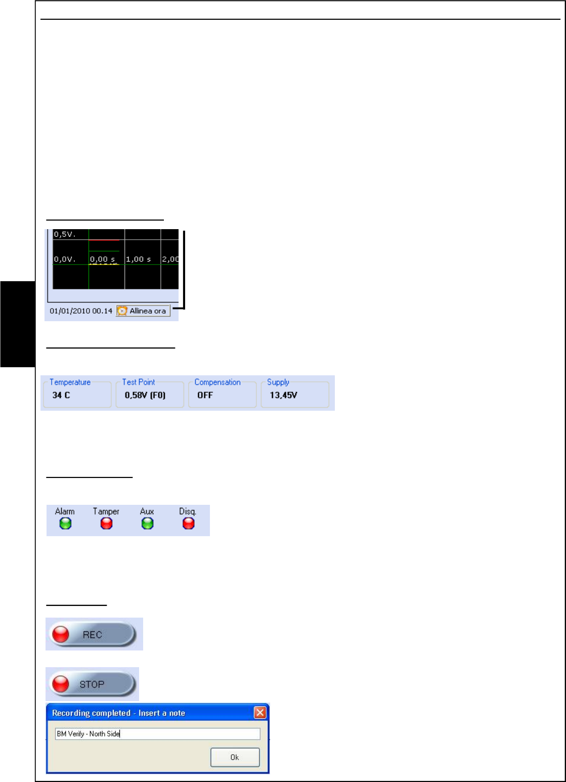
Adjust time and date
Select "Align time" to synchronise the time and date to that of the PC.
This setting is important for managing the events history of the barrier
Parameters displaying
These parameters highlight:
Temperature: : indicates the
functioning temperature of the receiver.
Test Pont: indicates the value of the
received signal.
Compensation: indicates, if the function is active (DIP 6 = ON), the integration value.
Power supply: indicates the power supply present on the receiver
Outputs Status
This section indicates the status of the receiver:
Alarm: if the barrier is in alarm, the red LED activates
Tamper: if the barrier is tampered with, the red LED activates
Disqualification: if the barrier is in disqualification (lowering of
the constant signal (>30sec.)), the red LED activates
Aux: if the barrier's auxiliary input is open, the red LED activates (DIP 8 =OFF the barrier does
not consider the input)
Recording
The "REC" button allows the installer to start recording what happens to the
barrier on the PC. All signals will be directly saved on to an archive on the
PC that can be accessed at any time. This function is very interesting when
wanting to check the detection zones of the barrier or monitor its behaviour.
The "STOP" button interrupts the recording.
It will be requested to "Enter a note" used to distinguish
the various files of the recordings history.
To display, it is necessary to consult "Recordings
Archive" and select the file.
E
N
G
- 59 -
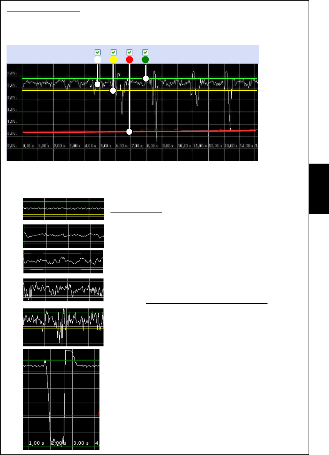
Oscilloscope function
This application enables checking the barrier signals in real time.
Timescale: it selects the timescale on the axis of ordinates.
Traces to display: it enables the displaying of traces.
White line: it indicates the signal received from the barrier
Red line: it indicates the set threshold alarm
Green/yellow line: it indicates the valid signal threshold; the signals inside the two lines do not
start the integration circuit of the signal (compensation)
Signal received
The quality of the signal depends on many factors, mainly
environmental. A stable installation passes through the research
for minimum disturbance on the barrier. For a correct installation,
it is important to keep away all those objects that might oscilla-
te in the presence of wind, for example, hedges, branches,
metal nets, etc. It is some times sufficient to slightly adjust both
pairs from the opposite side compared to the possible
disturbance to make the barrier stable, being careful that this
does not jeopardise the signal level.
EXAMPLES OF RECEIVED SIGNALS
ŒGood signal
•Slightly disturbed signal
ŽDisturbed signal - it is necessary to check if, by
adjusting, the disturbance reduces.
•Very disturbed signal - it is necessary to check there
are no oscillating objects within the zone of interest
of the barrier; it may be necessary to move the
barriers away from the disturbance.
•Very disturbed signal with accentuated risk of
unwanted alarms.
‘Alarm signal.
Œ
•
Ž
•
•
‘
Green L.
Yellow L.
Red L.
Traces to display
E
N
G
- 60 -
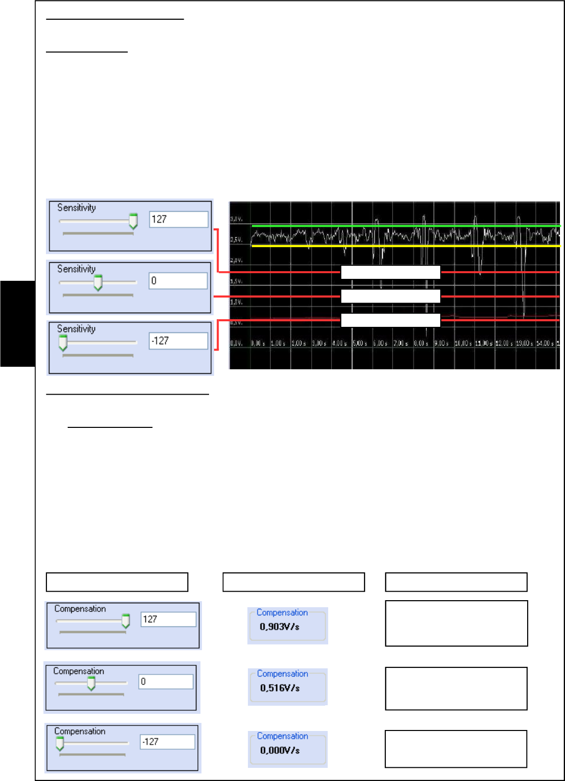
Sensitivity management
To obtain maximum possibility of managing the barrier settings, we recommend setting the
SENS trimmer on the receiver at halfway of its run.
This setting on the barrier allows the complete management of the sensitivity, even with connection
from PC.
The graphic displaying is had by checking the position of the RED line on the oscilloscope. The
closest the line to the upper part and, therefore, to the barrier signal (white line), the more sensitivity
increases.
The numerical indications (127 / - 127) indicate by how much, in percentage, the signal increases
or decreases, compared to the trimmer position adjusted in barrier.
The setting at (0) zero, displays the exact adjustment of the sensitivity on the barrier without any
influence by the management software.
Compensation management
To obtain maximum possibility of managing the barrier settings, we recommend setting
the COMP trimmer on the receiver at halfway of its run.
This setting on the barrier allows the complete management of the compensation, even with
connection from PC.
The "Compensation" value (xx) indicates that the alarm threshold line (Red line) rises by xx Volts
per second only when the microwave signal is disturbed enough to come out from the window
fixed by the two yellow and green lines.
The numerical indications (127 / - 127) indicate by how much compensation increases or
decreases, compared to the trimmer position adjusted in barrier.
The setting at (0) zero, displays the exact adjustment of the compensation on the barrier without
any influence by the management software.
Low Sensitivity
Middle Sensitivity
Cursor position Compensation V/sec. Description
High compensation
intervention.
Average compensation
intervention.
Compensation does not
intervene.
Hight Sensitivity
E
N
G
- 61 -
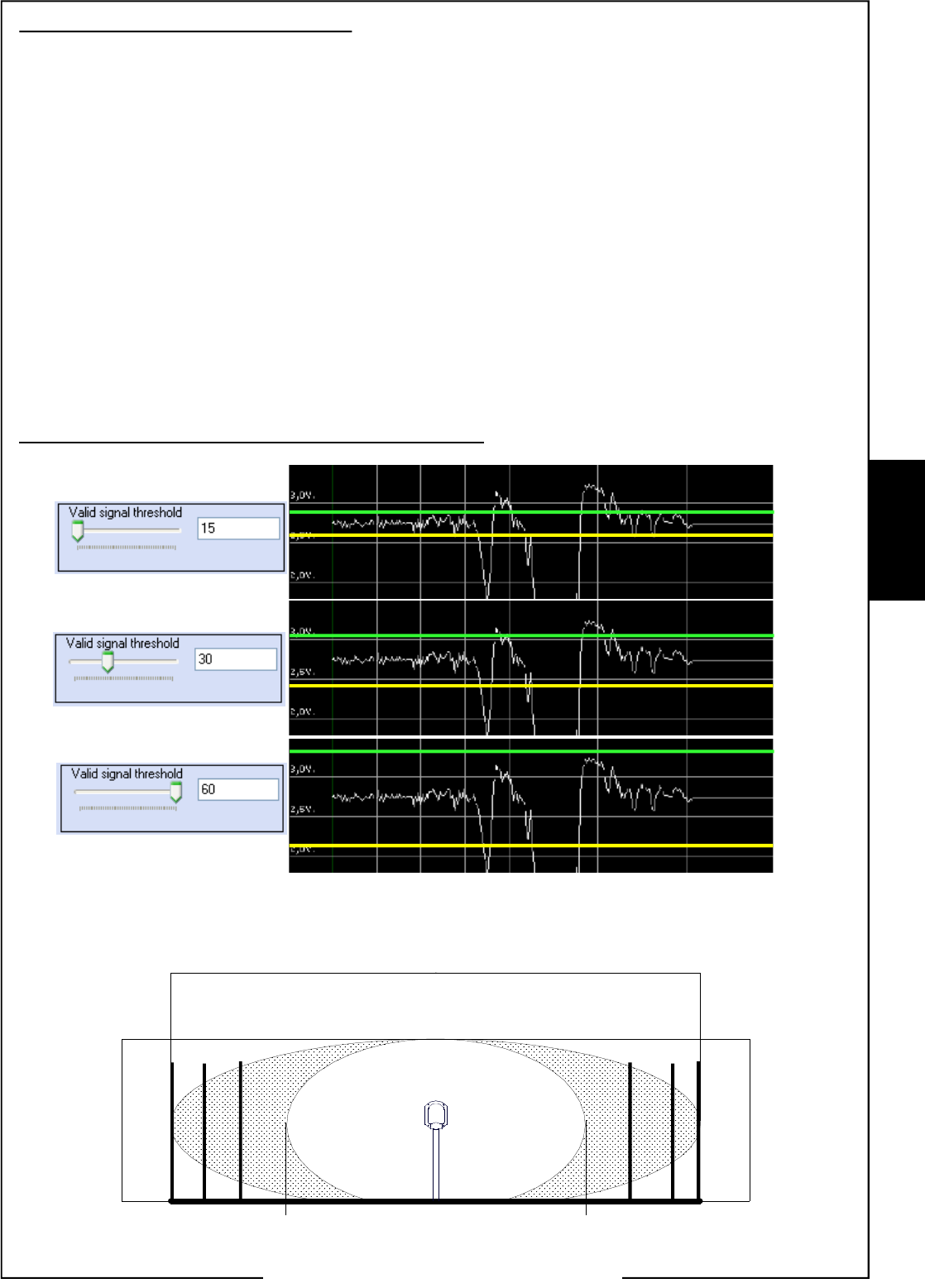
Valid signal threshold management
This particular function, called WIND UP can be programmed only with the use of the HPSOFT
software; it enables selection of the intervention zone of the barrier. It is possible to virtually
reduce the analysis lobe, enabling to select all those situations that might create system instability.
Often the generated lobe interests lateral zones where, the presence of hedges, metal nets or
other, create continuous disturbance. The WIND UP function enables modulating the lobe at
software level, until it becomes 20%-30% smaller than that declared. Usually the lobe creates a
sort of cigar effect between TX and RX; by activating the WIND UP function, the cylindrical
shape of the lobe will be amended creating a real and proper ellipse.
This function ensures that the compensation is not activated for signals inside the yellow and
green lines, indicating the valid signal threshold.
The signal is considered valid when it overcomes the reference lines.
The graphic displaying is had by checking the position of the YELLOW AND GREEN lines on the
oscilloscope. The greater the distance between the lines, the more the barrier rejects signals that
would activate compensation with factory adjustments.
The numerical indications (15 - 30 - 60) indicate by how much the valid signal threshold of the
barrier increases or decreases.
Graphic displaying on the management software.
Graphic indication of the possible reduction of the signal threshold.
The indications below are merely indicative. Only a field test will precisely indicate the coverage
zone and the valid signal thresholds.
Green L.
Yellow L.
Green L.
Yellow L.
Green L.
Yellow L.
Œ
•
Ž
BM60HP
6,5 meters
BM120HP
10 meters
BM200HP
16 meters
BM60HP
2 meters
BM120HP - BM200HP
3 meters
BM60HP 1,2 meters
BM120HP 3 meters
BM200HP 4 meters
Sensitive zone Sensitive zone
Œ•Ž Œ
•Ž
Alarm Zone
E
N
G
- 62 -
Detection mode
The possibility of alternating between the two functioning methods is possible only with the use
of the HPSOFT software.
Detection mode NORMAL: as the term indicates, the barrier behaves as describes up to now,
generating the alarm when the signal drops below the sensitivity threshold line and this does not
coincide with the waveforms customised library, relating to possible "False alarms".
Detection mode ALARM IDENTIFY: the barrier will go in alarm only if the detected signal coincides
with one of those recorded in the waveforms customised library as "real alarm".
This detection mode can be used when wanting to detect only particular types of crossings. To
use this opportunity, carry out a series of passages to generate alarms. Once a sufficient number
of alarm signals have been caused, check the "events history" in barrier and transfer the alarm
signals on to the "real alarm" customised library.
The barrier will then generate the alarm only for signals similar to those saved in this library;
every other signal will not generate an alarm.
This solution can be of interest if wanting to detect only the transiting of heavy means (cars/
articulated lorries, etc.), but not the transiting of persons or other.
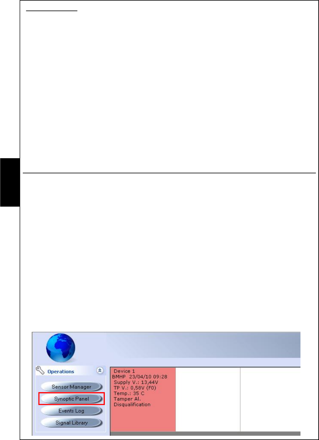
Synoptic panel
Access to this menu imposes to choose the type of connection; USB - PSTN/GSM.
For a connection in local it is necessary:
1- to power the barriers
2- to connect the barrier receiver to the computer using the USB connection.
note: if first connection, carry out the drivers loading procedure for the recognition of the peripheral.
3- to select the barrier address on HPSOFT and then choose "connect"
Once connected, it will be possible to display in real time, the information relating to all connected
barriers.
If we were connected to a barrier in USB its status would be verified, but if we were connected to
the serial satellite, we would be able to see the status of all active barriers in the system.
Displayed elements:
- Barrier's time and date settings
- power supply
- Test point
- Temperature in barrier
- Barrier status: Alarm - Tamper - Disqualification
E
N
G
- 63 -
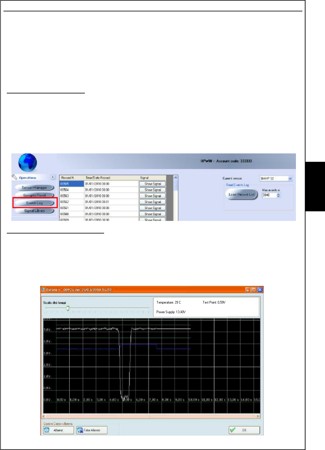
Events History
Access to this menu imposes to choose the type of connection; USB - PSTN/GSM.
For a connection in local it is necessary:
1- to power the barriers
2- to connect the barrier receiver to the computer using the USB connection.
note: if first connection, carry out the drivers loading procedure for the recognition of the peripheral.
3- to select the barrier address on HPSOFT and then choose "connect"
Once connected, access will be gained to the alarm events history recorded in barrier.
Data loading procedure
1- Select the satellite - the barrier: "current satellite"-"current detector"
2-Define the number of events to load, with a maximum of 3840: "Max n. events"
3- Start the process: press "Load Record List"
4- The events complete with Record Number, Date and time, will be displayed.
Signals displaying procedure
5- 5- Click on show signal; the software will load the information directly from the barrier
The displaying is complete of certain information recorded at the time of alarm:
- Alarm signal - Test Point - Power supply - Temperature.
6- Press Ok to close the screen
•
•
Ž
•
‘
ŒE
N
G
- 64 -
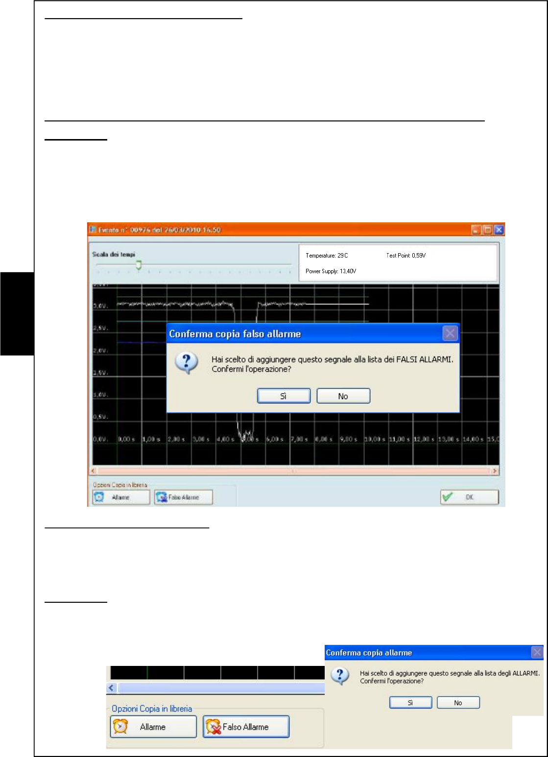
"False Alarm" library customisation
It is possible to create a waveforms customised archive to modulate the reply of the barrier
depending on the environmental contexts.
The signals transferred in the archive called "False Alarm", are verified by the microprocessor
before activating the real and proper alarm signal. If there were a correspondence between the
recorded signal and the generated waveform, the barrier will not activate any signal, considering
the event a false alarm.
We recommend setting in this archive only the ascertained false alarm signals.
Procedure:
1- Click on "False Alarm"; it will be requested to confirm the operation.
2- Press Yes to confirm; the wording "sample added to the library with success" confirms the
operation. If the procedure is rejected, it means that signal is not recognised among those that
can be customised.
3- Press No to desert the procedure
"Alarm" library customisation
This library is linked to the detection mode of the barrier.
The barrier checks this archive when the barrier is set in "ALARM IDENTIFY" detection mode;
the barrier will be alarmed only if the detected signal coincides with one of those recorded in this
archive.
Procedure:
1- Click on "Alarm"; it will be requested to confirm the operation.
2- Press Yes to confirm; the wording "sample added to the library with success" confirms the
operation.
3- Press No to desert the procedure
Œ
•Ž
Œ
•Ž
E
N
G
- 65 -
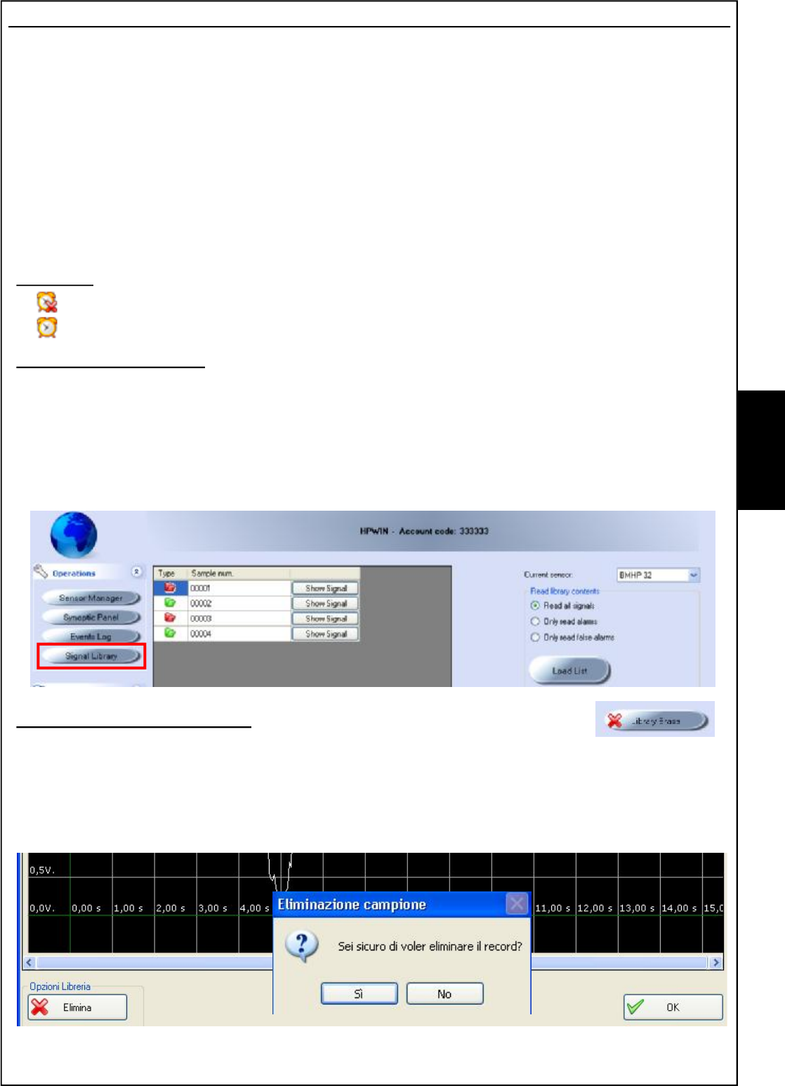
Signals library
Access to this menu imposes to choose the type of connection; USB - PSTN/GSM.
For a connection in local it is necessary:
1- to power the barriers
2- to connect the barrier receiver to the computer using the USB connection.
note: if first connection, carry out the drivers loading procedure for the recognition of the peripheral.
3- to select the barrier address on HPSOFT and then choose "connect"
Once connected, access is gained to the library of signals recorded in barrier by the installer.
Signals considered "FALSE ALARM" and others considered as "ALARM" can be found in this
customised library.
Symbols:
FALSE ALLARM
ALLARM
Data loading procedure
1- Select the satellite - the barrier: "current satellite"-"current detector"
2- Select which type of signal is to be loaded
3- Start the process: press "Load Record List"
4- The events complete of Record Number and "ALARM/FALSE ALARM" symbol will be displayed
5- To completely delete the signals library: press "Empty Library"
Signals displaying procedure
6- Click on show signal; the software will load the information directly
from the barrier and the saved signal will be displayed.
7- Press Ok to close the screen
8- Press "Delete" to delete this signal from the library and confirm.
9- Confirm deletion of the signal.
Œ
•
Ž
•
•
‘
’“ ”
E
N
G
- 66 -
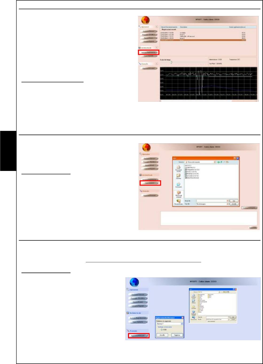
Recordings Archive
The archive of the recordings enables
displaying the signals recorded by the installer
on PC using the "recording" procedure
described in the "Detectors Management"
chapter.
By entering this archive, access will be gained
to a database where the various files will be
saved with date/time, description and duration
of recording.
Data access procedure
1- Select: "Recordings Archive"
2- Select the file to be loaded
3- To scroll the oscilloscope trace, drag the
cursor found on the lower section
System notes
In this section it is possible to load an image
reminding us, for example, where the barriers
are installed. It is also possible to enter notes
on the editable paragraph.
Access procedure
1- Select: "System Notes"
2- Select "Change image" to load a file.
3- "Select "save notes" to confirm
Upgrade Firmware
In this section it is possible to upgrade the barrier firmware. This procedure is only necessary if
AVS Electronics issues upgraded firmware versions. There is a section on the site dedicated to
the DOWNLOAD of files (http://www.avselectronics.com/PHP/login.php).
Access procedure
1- Select: "Upgrade Firmware"
2- Select the barrier to be upgraded
3- Select "Upgrade"
4- Select the file and confirm
Œ
•
Ž
Œ
•
Ž
•
Œ
•
Ž
E
N
G
- 67 -
E
N
G
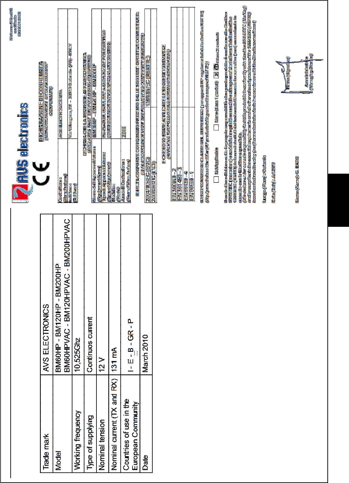
Information in conformity to the Directive 1999/5/CEE for model BM_HP
The product here described is in conformity to the essential prescriptions of the Directive 1999/5/CEE
(R&TTE) on the radio-transmitting devices of low power and on the use of frequencies of the radioelectrical
spectrum, in accordance with CEPT 70-03 recommandation.
NOTICE:
This device complies with Part 15 of the FCC Rules.
Operation is subject to the following two conditions:
(1) this device may not cause harmful interference, and
(2) this device must accept any interference received, including interference that may cause undesired
operation.
Changes or modifications made to this equipment not expressly approved by AVS Electronics S.p.A.
may void the FCC authorization to operate this equipment.
NOTE: This equipment has been tested and found to comply with the limits for a Class B digital device,
pursuant to Part 15 of the FCC Rules. These limits are designed to provide reasonable protection
against harmful interference in a residential installation. This equipment generates, uses and can
radiate radio frequency energy and, if not installed and used in accordance with the instructions, may
cause harmful interference to radio communications. However, there is no guarantee that interference
will not occur in a particular installation. If this equipment does cause harmful interference to radio or
television reception, which can be determined by turning the equipment off and on, the user is encouraged
to try to correct the interference by one or more of the following measures:
•Reorient or relocate the receiving antenna.
•Increase the separation between the equipment and receiver.
•Connect the equipment into an outlet on a circuit different from that to which the receiver is connected.
•Consult the dealer or an experienced radio/TV technician for help.
- 68 -
Via Valsugana, 63
35010 (Padova) ITALY
Tel. +39 049 9698 411 / Fax. +39 049 9698 407
avs@avselectronics.it
www.avselectronics.com
Assistenza Tecnica: +39 049 9698 444
support@avselectronics.it
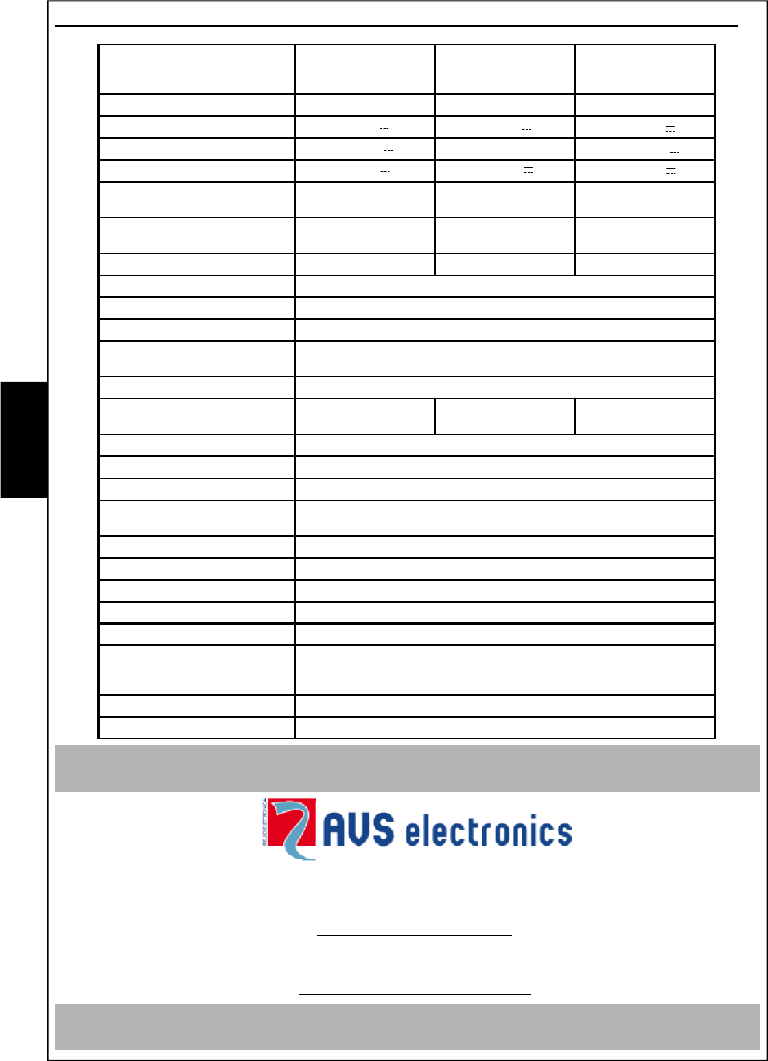
Technical Characteristics
E
N
G
AVS ELECTRONICS S.p.A. reserves the right to modify the technical and esthetical characteristic of the products at any time.
BM60HP
BM60HPVAC
BM120HP
BM120HPVAC
BM200HP
BM200HPVAC
Max range 60 meters 120 meters 200 meters
Nominal tension 12 V 12 V 12 V
Min tension 11.5 V 11.5 V 11.5 V
Max tension 15 V 15 V 15 V
Consumption during quiet TX : 31 mA
RX : 100 mA
TX : 31 mA
RX : 100 mA
TX : 31 mA
RX : 100 mA
Consumption during alarm TX : 31 mA
RX : 100 mA
TX : 31 mA
RX : 100 mA
TX : 31 mA
RX : 100 mA
Size: (P x L x H) 150 x 105 x 195 136 x 225 x 225 136 x 225 x 225
Block of detector relay by appointed terminal B
Auxiliary input Negative input for detector
Alarm output n.c. exchange with 500 mA range at 12 V
Disqualification output normally closed good reception control exchange of signal with range
500 mA at 12 V
Tamper output n.c. exchange with 500 mA range at 12 V
Optional kit for anti-removal
(AMP) no yes yes
Serial output - RS485 yes
Selectable serial addresses Maximum 32
Events memory Up to 3600 events recorded with time and date
Stop recording with system
disarmed
yes
Filter false alarms yes
Test Point output for checking of signal received
Mirowave working frequency 10,525 GHz (+/-20MHz)
Modulation in 5 different channels, selection through dip-switch
Irradiation of RF power peak: 25 dBm
Temperature conditions from - 20°C to + 55°C
For installation outdoor, the use of the optional heating kit (Term2) is
suggested .
IP Protection IP 34
Given within Bracket for fixation on 40 mm tube