Aastra 41 001343 02 Users Manual 6700i, 6800i, And 9000i Series SIP IP Phones
4100134302 3d3e31cb-27ce-4397-ae7e-70cbe1bbb7d8 Aastra Telecom IP Phone 41-001343-02 User Guide |
2015-02-02
: Aastra Aastra-41-001343-02-Users-Manual-402236 aastra-41-001343-02-users-manual-402236 aastra pdf
Open the PDF directly: View PDF ![]() .
.
Page Count: 876 [warning: Documents this large are best viewed by clicking the View PDF Link!]
- Software License Agreement
- Content
- Preface
- Chapter 1 Overview
- Topics
- IP Phone Models
- Description
- Optional Accessories
- Model 6730i IP Phone
- Model 6731i IP Phone
- Model 6735i IP Phone
- Model 6737i IP Phone
- Model 6739i IP Phone
- Model 6753i IP Phone
- Model 6755i IP Phone
- Model 6757i and 6757i CT IP Phones
- Model 6863i IP Phone
- Model 6865i IP Phone
- Model 6867i IP Phone
- Model 9143i IP Phone
- Model 9480i and 9480i CT IP Phones
- Firmware Installation Information
- Firmware and Configuration Files
- Chapter 2 Configuration Interface Methods
- Chapter 3 Administrator Options
- Topics
- Administrator Level Options
- Description
- IP Phone UI Options
- Aastra Web UI Options
- Configuration File Options
- Phone Status
- Restarting Your Phone
- Set Phone to Factory Defaults/Erase Local Configuration
- Basic Settings
- Account Configuration
- Network Settings
- Line Settings
- Softkeys, Programmable Keys, Expansion Module Keys
- Action URI
- Configuration Server Settings
- Firmware Update Features
- TLS Support
- 802.1x Support
- Troubleshooting
- Chapter 4 Configuring Network and Session Initiation Protocol (SIP) Features
- About this Chapter
- Overview
- Network Settings
- Basic Network Settings
- DHCP
- DHCP Options 60, 66, and 43 Server Configurations
- Using Option 43 to Customize the IP Phone
- Option 43 Redirection and Configuration Server (RCS) Bypass
- Using Option 120 on the IP Phone
- Using Option 132 (802.1P VLAN ID) and Option 43 to Transfer VLAN ID Assignment Using DHCP
- Using Option 12 Hostname on the IP Phone
- Using Option 77 User Class on the IP Phone
- Using Options 159 and 160 on the IP Phone
- Configuration Server Download Precedence
- Multiple DHCP Servers
- DNS Caching
- Configuring Network Settings Manually
- Configuring LAN and PC Port Negotiation
- Advanced Network Settings
- Network Address Translation (NAT)
- Configuring NAT Address and Port (optional)
- SIP and TLS Source Ports for NAT Traversal
- STUN and TURN Protocols
- Interactive Connectivity Establishment (ICE) Support
- HTTPS Client/Server Configuration
- HTTPS Server Certificate Validation
- Virtual LAN (optional)
- Type of Service (ToS), Quality of Service (QoS), and DiffServ QoS
- RPORT
- Network Time Servers
- Basic Network Settings
- Global SIP Settings
- Description
- Basic SIP Settings
- SIP Global Parameters
- SIP Per-Line Parameters
- SIP Password Masking
- SIP Precedence Example
- Backup Proxy/Registrar Support
- SIP Outbound Support
- Enabling/Disabling SIP Outbound Draft 15 Support
- Backup Outbound Proxy and Failover Support
- SIP Server (SRV) Lookup
- Contact Header Matching
- Configuring Basic SIP Authentication Settings
- Configuring Basic SIP Network Settings (optional)
- Advanced SIP Settings (optional)
- Real-time Transport Protocol (RTP) Settings
- RTCP Summary Reports
- Autodial Settings
- Configuration Server Protocol
- Chapter 5 Configuring Operational Features
- About this Chapter
- Operational Features
- Description
- User Passwords
- Administrator Passwords
- Locking/Unlocking the Phone
- Defining an Emergency Dial Plan
- Configurable Emergency Call Behavior
- User Dial Plan Setting
- Time and Date
- Backlight Mode
- Display
- Background Image on Idle Screen
- Configurable Home/Idle Screen Modes
- Picture ID Feature
- Audio DHSG Headset
- Configurable Bluetooth Support
- Audio Hi-Q on G.722 Calls
- Wideband Audio Equalizer
- Audio Transmit and Receive Gain Adjustments
- Live Dialpad
- Language
- Minimum Ringer Volume
- Locking IP Phone Keys
- Locking/Unlocking the SAVE and DELETE keys
- Local Dial Plan
- Suppressing DTMF Playback
- Display DTMF Digits
- Filter Out Incoming DTMF Events
- Call Waiting
- Stuttered Dial Tone
- XML Beep Support
- Status Scroll Delay
- Switch Focus to Ringing Line
- Call Hold Reminder During Active Calls
- Call Hold Reminder (on Single Hold)
- Call Hold Reminder Timer & Frequency
- Preferred Line and Preferred Line Timeout
- Goodbye Key Cancels Incoming Call
- Message Waiting Indicator Line
- Customizable Message Waiting Indicator (MWI) Request URI
- DND Key Mode
- Call Forward Mode
- Link Layer Discovery Protocol for Media Endpoint Devices (LLDP-MED) and Emergency Location Identification Number (ELIN)
- Incoming/Outgoing Intercom with Auto-Answer and Barge In
- Group Paging RTP Settings
- Speeddial Key Mapping
- Send DTMF for Remapping Conference or Redial Key
- Ring Tones and Tone Sets
- Ring Tone via Speaker During Active Calls
- No Service Congestion Tone
- Priority Alerting
- Directed Call Pickup (BLF or XML Call Interception)
- Softkeys/Programmable Keys/Feature Keys/Expansion Module Keys
- Shifting of Softkey Positions for Busy States
- Option to Remove the “More” Softkey when Not Required
- Increased Number of Displayed Characters for Softkey Line Labels
- 6757i Cordless (CT) Feature Keys
- Press-and-Hold Speeddial Keypad Keys
- 6867i Hard Key Reprogramming
- Customizing the Key Type List in the Aastra Web UI
- Speeddial Prefixes
- Enabling/Disabling Ability to Add or Edit a Speeddial Key
- Busy Lamp Field (BLF)
- BLF Page Switch Feature
- Configurable Display for Blank BLF/List Softkeys
- Ring Signal Type for BLF
- BLF Subscription Period
- BLF/Xfer and Speeddial/Xfer Keys
- Speeddial/Conference Key
- Speeddial/MWI Key
- Automatic Call Distribution (ACD) (for Sylantro Servers)
- ACD Auto-Available Timer
- Configuring an Automatic Call Distribution (ACD) Key
- Configuring the ACD Auto-Available Timer
- Configuring an ACD Key Using the Aastra Web UI
- Configuring the ACD Auto-Available Timer Using the Aastra Web UI
- Using the ACD Feature on your IP Phone
- Logging In to a Phone Queue
- ACD Subscription Period
- Configuring ACD Subscription Period
- Directed Call Pickup/Group Call Pickup
- Do Not Disturb (DND)
- DND Account-Based Configuration
- Configuring DND Using the Configuration Files
- Configuring DND Using the Aastra Web UI
- Configuring DND via the IP Phone UI (3-Line Phones)
- Configuring DND via the IP Phone UI (8-Line and 11-Line Phones)
- Configuring DND Modes via the IP Phone UI (6739i)
- Configuring DND Using the IP Phone UI (6867i)
- Bridged Line Appearance (BLA)
- BLA Support for Third-Party Registration
- P-Preferred Identity Header for BLA Accounts
- BLA Support for Message Waiting Indicator (MWI)
- Shared Call Appearance (SCA) Call Bridging
- Park/Pick Up Static and Programmable Configuration
- Enhanced Park/Pickup Configuration Method (BroadSoft BroadWorks)
- Last Call Return (lcr) (Sylantro Servers)
- Call Forwarding
- SIP Phone Diversion Display
- Display Name Customization
- Displaying Call Destination for Incoming Calls
- Callers List
- Customizable Callers List and Services Keys
- Missed Calls Indicator
- Directory List
- Directory List Capabilities
- Reference
- Administrator/User Functions for Directory List
- Enabling/Disabling Directory List
- Server to IP Phone Download
- Server to IP Phone Download Behavior
- Directory List Limitations
- Using the Directory List
- Downloading from the Server to the IP Phone
- Downloading from the IP Phone to the Server
- Local Directory Loose Number Matching
- Configuring Local Directory Loose Number Matching
- Customizable Directory List Key
- Voicemail
- Visual Indicators for Voicemail on SCA-Configured Lines
- PIN and Authorization Code Suppression
- XML Customized Services
- Creating Customized XML Services on the IP Phones
- Reference
- Enabling/Disabling a Beep for Status Message Displays
- Reference
- Scroll Delay Option for Status Messages
- Reference
- XML Configuration Push from the Server
- Configuring the Phone to use XML
- XML Get Timeout
- Configuring for XML on the IP Phone
- Using the XML Customized Service
- Reference
- Action URIs
- Polling Action URIs
- Action URI Connected
- Action URI Disconnected
- XML SIP Notify Events
- XML Softkey URI
- XML Key Redirection
- Options Key Redirection
- XML Applications and Off-Hook Interaction
- XML URI for Key Press Simulation
- XML Override for a Locked Phone
- Configurable Indication of Terminated Calls
- Centralized Conferencing (for Sylantro and Broadsoft Servers)
- Custom Ad-Hoc Conference
- “SIP Join” Feature for 3-Way Conference
- Conference/Transfer Support for Live Dial Mode
- Authentication Support for HTTP/HTTPS Download Methods, used with Broadsoft Client Management System (CMS)
- Customizing the Display Columns on the M675i Expansion Module
- Chapter 6 Configuring Advanced Operational Features
- About this Chapter
- Advanced Operational Features
- Description
- TR-069 Support
- MAC Address/Line Number in REGISTER Messages
- SIP Message Sequence for Blind Transfer
- SIP Message Sequence for Semi-Attended Transfer
- Update Caller ID During a Call
- Boot Sequence Recovery Mode
- Auto-discovery Using mDNS
- Single Call Restriction
- Missed Call Summary Subscription
- As-Feature-Event Subscription
- Blacklist Duration
- Whitelist Proxy
- Transport Layer Security (TLS)
- 802.1x Support
- Symmetric UDP Signaling
- Symmetric TLS Signaling
- Removing UserAgent and Server SIP Headers
- GRUU and sip.instance Support
- Multi-Stage Digit Collection (Billing Codes) Support (for Sylantro Servers)
- Configurable DNS Queries
- Ignore Out of Sequence Errors
- “Early-Only” Parameter in Replaces Header RFC3891
- Switching Between Early Media and Local Ringing
- Enable Microphone During Early Media
- “Call-Info” Header to 200ok Responses for Shared Call Appearance (SCA) Lines
- Reason Header Field in SIP Message
- Configurable “Allow” and “Allow-Event” Optional Headers
- Configurable SIP P-Asserted Identity (PAI)
- Configurable Route Header in SIP Packet
- Configurable Compact SIP Header
- Reject INV or BYE when Unsupported Value in REQUIRE Header
- XML URI for Key Press Simulation
- Domain Name System (DNS) Server Pre-caching Support
- Configurable Transport Protocol for SIP Services and RTCP Summary Reports
- Configurable Alphanumeric Input Order for Username Prompts
- Active Voice-over-IP (VoIP) Recording
- BroadSoft BroadWorks Executive and Assistant Services Feature
- Chapter 7 Encrypted Files on the IP Phone
- Chapter 8 Upgrading the Firmware
- Chapter 9 Troubleshooting
- About this Chapter
- Troubleshooting
- Troubleshooting Solutions
- Description
- Why does my phone display “Application missing”?
- Why does my phone display the “No Service” message?
- Why does my phone display "Bad Encrypted Config"?
- Why is my phone not receiving the TFTP IP address from the DHCP Server?
- How do I restart the IP phone?
- How do I set the IP phone to factory default?
- How do I erase the phone’s local configuration?
- How to reset a user’s password?
- How do I lock and unlock the phone?
- Appendix A Configuration Parameters
- About this Appendix
- Setting Parameters in Configuration Files
- Operational, Basic, and Advanced Parameters
- Simplified IP Phone UI Options Menu
- Network Settings
- DHCP Option Settings
- Password Settings
- Emergency Dial Plan Settings
- Emergency Call Behavior Settings
- User Dial Plan Setting
- Aastra Web UI Settings
- Configuration Server Settings
- Multiple Configuration Server Settings
- Network Address Translation (NAT) Settings
- Rport Setting
- Local SIP UDP/TCP Port Setting
- Local SIP TLS Port
- SIP STUN Parameters
- SIP TURN Parameters
- SIP Keep Alive Support
- HTTPS Client and Server Settings
- HTTPS Server Certificate Validation Settings
- Virtual Local Area Network (VLAN) Settings
- RTCP Summary Reports
- Type of Service (ToS)/DSCP Settings
- Time and Date Settings
- Time Server Settings
- Custom Time Zone and DST Settings
- Backlight Mode Settings
- Brightness Level Settings
- Background Image on Idle Screen
- Configurable Home/Idle Screen Modes
- Picture ID Feature
- DHSG Settings
- Bluetooth Support Settings
- Wideband Audio Equalizer Settings
- Live Dialpad Settings
- SIP Local Dial Plan Settings
- SIP Outbound Support
- Contact Header Matching
- SIP Basic, Global Settings
- Backup Outbound Proxy (Global Settings)
- SIP Basic, Per-Line Settings
- Backup Outbound Proxy (Per-line Settings)
- BLA Support for MWI
- Shared Call Appearance (SCA) Call Bridging
- Centralized Conferencing Settings
- Custom Ad-Hoc Conference
- SIP Join Feature for 3-Way Conference
- Conference/Transfer in Live Dial Mode
- HTTP/HTTPS Authentication Support for Broadsoft CMS
- Advanced SIP Settings
- Missed Call Summary Subscription Settings
- As-Feature-Event Subscription Settings
- Transport Layer Security (TLS) Settings
- 802.1x Support Settings
- RTP, Codec, DTMF Global Settings
- Autodial Settings
- Voicemail Settings
- SCA Voicemail Indicator Settings
- Directory Settings
- Customizable Directory List Key
- Callers List Settings
- Customizable Callers List and Services Key
- Call Forward Settings
- Call Forward Key Mode Settings
- PIN Suppression
- LLDP-MED and ELIN Settings
- Missed Calls Indicator Settings
- XML Settings
- Action URI Settings
- XML SIP Notify Settings
- Polling Action URI Settings
- Ring Tone and Tone Set Global Settings
- Ring Tone Per-Line Settings
- Ring Tone via Speaker During Active Calls Settings
- No Service Congestion Tone Settings
- Status Code on Ignoring Incoming Calls
- Switch Focus to Ringing Line
- Call Hold Reminder Settings
- Preferred Line and Preferred Line Timeout
- Goodbye Key Cancels Incoming Call
- Stuttered Dial Tone Setting
- Message Waiting Indicator Settings
- Message Waiting Indicator Request URI Setting
- DND Key Mode Settings
- Priority Alert Settings
- Bellcore Cadence Settings
- SIP Diversion Display
- Display Name Customization Settings
- Language Settings
- Language Pack Settings
- Suppress DTMF Playback Setting
- Display DTMF Digits Setting
- Filter Out Incoming DTMF Events
- Intercom, Auto-Answer, and Barge In Settings
- Enable Microphone During Early Media
- Group Paging RTP Settings
- Audio Transmit and Receive Gain Adjustment Settings
- Disable User Login to Aastra Web UI
- Minimum Ringer Volume
- Terminated Calls Indicator
- Directed Call Pickup (BLF or XML Call Interception) Settings
- ACD Auto-Available Timer Settings
- Mapping Key Settings
- Send DTMF for Remapping Conference or Redial Key
- Park and Pickup Settings
- Softkey/Programmable Key/Keypad Key/Feature Key/Expansion Module Key/Hard Key Parameters
- Softkey Settings
- Shifting of Softkey Positions for Busy States
- Option to Remove the “More” Softkey when Not Required
- Increase of Displayed Characters for Softkey Line Labels
- Programmable Key Settings
- Top Softkey Settings
- Press-and-Hold Speeddial Keypad Key Settings
- Handset Feature Key Settings
- Expansion Module Key Settings for M670i , M675i, and M680i
- Hard Key Settings for 6867i
- Customizing the Key Type List
- Locking Keys
- Locking the SAVE and DELETE Keys
- Enabling/Disabling Ability to Add/Edit Speeddial Keys
- BLF List URI Settings
- BLF Page Switch
- Configurable Display for Blank BLF/List Softkeys
- Ring Splash Settings
- Customizing M675i Expansion Module Column Display
- Advanced Operational Parameters
- Blind Transfer Setting
- Semi-Attended Transfer Settings
- Update Caller ID Setting
- Boot Sequence Recovery Mode Settings
- Single Call Restriction Setting
- Blacklist Duration Setting
- Whitelist Proxy Setting
- XML Key Redirection Settings (for Redial, Xfer, Conf, Icom, Voicemail)
- Options Key Redirection Setting
- Off-Hook and XML Application Interaction Setting
- XML Override for a Locked Phone Setting
- Symmetric UDP Signaling Setting
- Symmetric TLS Signaling Setting
- User-Agent Setting
- GRUU and sip.instance Support
- DNS Query Setting
- Ignore Out of Order SIP Requests
- Optional “Allow” and “Allow-Event” Headers
- P-Asserted Identity (PAI)
- Route Header in SIP Packet
- Compact SIP Header
- Rejection of INV or BYE
- Configuration Encryption Setting
- DNS Host File
- DNS Server Query
- SIP Services/RTCP Summary Reports Transport Protocol Settings
- Alphanumeric Input Order for Username Prompts
- Active VoIP Recording Settings
- BroadSoft BroadWorks Executive and Assistant Services Settings
- Troubleshooting Parameters
- Appendix B Configuring the IP Phone at the Asterisk IP PBX
- Appendix C Sample Configuration Files
- Appendix D Sample BLF Softkey Settings
- Appendix E Sample Multiple Proxy Server Configuration
- Limited Warranty
- Limited Warranty (Australia Only)
- Index
- Third-Party Copyright Compliance
- Disclaimer
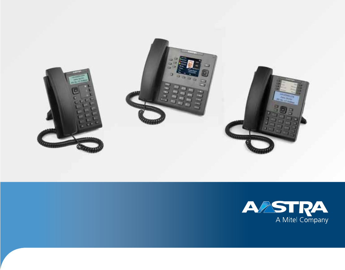
Aastra 6700i, 6800i, and 9000i Series
SIP IP Phones
Release 3.3.1 SP3
41-001343-02 REV04 – 05.2014
Administrator Guide

ii 41-001343-02 REV04 – 05.2014
Software License Agreement
Aastra, hereinafter known as "Seller", grants to Customer a personal, worldwide, non-transferable, non-sublicenseable
and non-exclusive, restricted use license to use Software in object form solely with the Equipment for which the Soft-
ware was intended. This Product may integrate programs, licensed to Aastra by third party Suppliers, for distribution
under the terms of this agreement. These programs are confidential and proprietary, and are protected as such by copy-
right law as unpublished works and by international treaties to the fullest extent under the applicable law of the jurisdic-
tion of the Customer. In addition, these confidential and proprietary programs are works conforming to the require-
ments of Section 401 of title 17 of the United States Code. Customer shall not disclose to any third party such confiden-
tial and proprietary programs and information and shall not export licensed Software to any country except in accord-
ance with United States Export laws and restrictions.
Customer agrees to not reverse engineer, decompile, disassemble or display Software furnished in object code form.
Customer shall not modify, copy, reproduce, distribute, transcribe, translate or reduce to electronic medium or machine
readable form or language, derive source code without the express written consent of the Seller and its Suppliers, or dis-
seminate or otherwise disclose the Software to third parties. All Software furnished hereunder (whether or not part of
firmware), including all copies thereof, are and shall remain the property of Seller and its Suppliers and are subject to the
terms and conditions of this agreement. All rights reserved.
Customer's use of this software shall be deemed to reflect Customer's agreement to abide by the terms and conditions
contained herein. Removal or modification of trademarks, copyright notices, logos, etc., or the use of Software on any
Equipment other than that for which it is intended, or any other material breach of this Agreement, shall automatically
terminate this license. If this Agreement is terminated for breach, Customer shall immediately discontinue use and
destroy or return to Seller all licensed software and other confidential or proprietary information of Seller. In no event
shall Seller or its suppliers or licensors be liable for any damages whatsoever (including without limitation, damages for
loss of business profits, business interruption, loss of business information, other pecuniary loss, or consequential dam-
ages) arising out of the use of or inability to use the software, even if Seller has been advised of the possibility of such
damages.
41-001343-02 REV04 – 05.2014 iii
Content
Software License Agreement . . . . . . . . . . . . . . . . . . . . . . . . . . . . . . . . . . . . . . . . . . . . . . . . . . . . . . . . . . . . . . . . . . . . . . . . .ii
Preface . . . . . . . . . . . . . . . . . . . . . . . . . . . . . . . . . . . . . . . . . . . . . . . . . . . . . . . . . . . . . . . . . . . . . . . . . . . . . . . . . . . . . . . . . . . . . . . . . . . . . xviii
Audience . . . . . . . . . . . . . . . . . . . . . . . . . . . . . . . . . . . . . . . . . . . . . . . . . . . . . . . . . . . . . . . . . . . . . . . . . . . . . . . . . . . . . . . . . . . . . . . . xviii
Documentation . . . . . . . . . . . . . . . . . . . . . . . . . . . . . . . . . . . . . . . . . . . . . . . . . . . . . . . . . . . . . . . . . . . . . . . . . . . . . . . . . . . . . . . . . xviii
Chapters and Appendices in this Guide . . . . . . . . . . . . . . . . . . . . . . . . . . . . . . . . . . . . . . . . . . . . . . . . . . . . . . . . . . . . . . . . . . . xix
Chapter 1:
Overview . . . . . . . . . . . . . . . . . . . . . . . . . . . . . . . . . . . . . . . . . . . . . . . . . . . . . . . . . . . . . . . . . . . . . . . . . . . . . . . . . . . . . . . . . . . . . . . . . . .1-1
About this Chapter . . . . . . . . . . . . . . . . . . . . . . . . . . . . . . . . . . . . . . . . . . . . . . . . . . . . . . . . . . . . . . . . . . . . . . . . . . . . . . . . . . . . . .1-1
Topics . . . . . . . . . . . . . . . . . . . . . . . . . . . . . . . . . . . . . . . . . . . . . . . . . . . . . . . . . . . . . . . . . . . . . . . . . . . . . . . . . . . . . . . . . . . . . . . . . . . .1-1
IP Phone Models . . . . . . . . . . . . . . . . . . . . . . . . . . . . . . . . . . . . . . . . . . . . . . . . . . . . . . . . . . . . . . . . . . . . . . . . . . . . . . . . . . . . . . . . .1-2
Description. . . . . . . . . . . . . . . . . . . . . . . . . . . . . . . . . . . . . . . . . . . . . . . . . . . . . . . . . . . . . . . . . . . . . . . . . . . . . . . . . . . . . . . . . . . . . . .1-2
Optional Accessories . . . . . . . . . . . . . . . . . . . . . . . . . . . . . . . . . . . . . . . . . . . . . . . . . . . . . . . . . . . . . . . . . . . . . . . . . . . . . . . . . . . . .1-4
Model 6730i IP Phone . . . . . . . . . . . . . . . . . . . . . . . . . . . . . . . . . . . . . . . . . . . . . . . . . . . . . . . . . . . . . . . . . . . . . . . . . . . . . . . . . . . .1-7
Model 6731i IP Phone . . . . . . . . . . . . . . . . . . . . . . . . . . . . . . . . . . . . . . . . . . . . . . . . . . . . . . . . . . . . . . . . . . . . . . . . . . . . . . . . . . 1-10
Model 6735i IP Phone . . . . . . . . . . . . . . . . . . . . . . . . . . . . . . . . . . . . . . . . . . . . . . . . . . . . . . . . . . . . . . . . . . . . . . . . . . . . . . . . . . 1-13
Model 6737i IP Phone . . . . . . . . . . . . . . . . . . . . . . . . . . . . . . . . . . . . . . . . . . . . . . . . . . . . . . . . . . . . . . . . . . . . . . . . . . . . . . . . . . 1-16
Model 6739i IP Phone . . . . . . . . . . . . . . . . . . . . . . . . . . . . . . . . . . . . . . . . . . . . . . . . . . . . . . . . . . . . . . . . . . . . . . . . . . . . . . . . . . 1-19
Model 6753i IP Phone . . . . . . . . . . . . . . . . . . . . . . . . . . . . . . . . . . . . . . . . . . . . . . . . . . . . . . . . . . . . . . . . . . . . . . . . . . . . . . . . . . 1-22
Model 6755i IP Phone . . . . . . . . . . . . . . . . . . . . . . . . . . . . . . . . . . . . . . . . . . . . . . . . . . . . . . . . . . . . . . . . . . . . . . . . . . . . . . . . . . 1-25
Model 6757i and 6757i CT IP Phones. . . . . . . . . . . . . . . . . . . . . . . . . . . . . . . . . . . . . . . . . . . . . . . . . . . . . . . . . . . . . . . . . . . . 1-28
Model 6863i IP Phone . . . . . . . . . . . . . . . . . . . . . . . . . . . . . . . . . . . . . . . . . . . . . . . . . . . . . . . . . . . . . . . . . . . . . . . . . . . . . . . . . . 1-33
Model 6865i IP Phone . . . . . . . . . . . . . . . . . . . . . . . . . . . . . . . . . . . . . . . . . . . . . . . . . . . . . . . . . . . . . . . . . . . . . . . . . . . . . . . . . . 1-35
Model 6867i IP Phone . . . . . . . . . . . . . . . . . . . . . . . . . . . . . . . . . . . . . . . . . . . . . . . . . . . . . . . . . . . . . . . . . . . . . . . . . . . . . . . . . . 1-38
Model 9143i IP Phone . . . . . . . . . . . . . . . . . . . . . . . . . . . . . . . . . . . . . . . . . . . . . . . . . . . . . . . . . . . . . . . . . . . . . . . . . . . . . . . . . . 1-41
Model 9480i and 9480i CT IP Phones. . . . . . . . . . . . . . . . . . . . . . . . . . . . . . . . . . . . . . . . . . . . . . . . . . . . . . . . . . . . . . . . . . . . 1-44
Firmware Installation Information . . . . . . . . . . . . . . . . . . . . . . . . . . . . . . . . . . . . . . . . . . . . . . . . . . . . . . . . . . . . . . . . . 1-49
Description. . . . . . . . . . . . . . . . . . . . . . . . . . . . . . . . . . . . . . . . . . . . . . . . . . . . . . . . . . . . . . . . . . . . . . . . . . . . . . . . . . . . . . . . . . . . . 1-49
Installation Considerations. . . . . . . . . . . . . . . . . . . . . . . . . . . . . . . . . . . . . . . . . . . . . . . . . . . . . . . . . . . . . . . . . . . . . . . . . . . . . 1-49
Installation Requirements . . . . . . . . . . . . . . . . . . . . . . . . . . . . . . . . . . . . . . . . . . . . . . . . . . . . . . . . . . . . . . . . . . . . . . . . . . . . . . 1-49

Content
iv 41-001343-02 REV04 – 05.2014
Configuration Server Requirement . . . . . . . . . . . . . . . . . . . . . . . . . . . . . . . . . . . . . . . . . . . . . . . . . . . . . . . . . . . . . . . . . . . . . 1-49
Firmware and Configuration Files. . . . . . . . . . . . . . . . . . . . . . . . . . . . . . . . . . . . . . . . . . . . . . . . . . . . . . . . . . . . . . . . . . 1-50
Description. . . . . . . . . . . . . . . . . . . . . . . . . . . . . . . . . . . . . . . . . . . . . . . . . . . . . . . . . . . . . . . . . . . . . . . . . . . . . . . . . . . . . . . . . . . . . 1-50
Configuration File Precedence. . . . . . . . . . . . . . . . . . . . . . . . . . . . . . . . . . . . . . . . . . . . . . . . . . . . . . . . . . . . . . . . . . . . . . . . . . 1-51
Installing the Firmware/Configuration Files . . . . . . . . . . . . . . . . . . . . . . . . . . . . . . . . . . . . . . . . . . . . . . . . . . . . . . . . . . . . 1-51
Multiple Configuration Server Support . . . . . . . . . . . . . . . . . . . . . . . . . . . . . . . . . . . . . . . . . . . . . . . . . . . . . . . . . . . . . . . . . 1-52
Chapter 2:
Configuration Interface Methods . . . . . . . . . . . . . . . . . . . . . . . . . . . . . . . . . . . . . . . . . . . . . . . . . . . . . . . . . . . . . . . .2-1
About this Chapter . . . . . . . . . . . . . . . . . . . . . . . . . . . . . . . . . . . . . . . . . . . . . . . . . . . . . . . . . . . . . . . . . . . . . . . . . . . . . . . . . . . . . .2-1
Topics . . . . . . . . . . . . . . . . . . . . . . . . . . . . . . . . . . . . . . . . . . . . . . . . . . . . . . . . . . . . . . . . . . . . . . . . . . . . . . . . . . . . . . . . . . . . . . . . . . . .2-1
Configuration Methods . . . . . . . . . . . . . . . . . . . . . . . . . . . . . . . . . . . . . . . . . . . . . . . . . . . . . . . . . . . . . . . . . . . . . . . . . . . . . . . .2-2
Description. . . . . . . . . . . . . . . . . . . . . . . . . . . . . . . . . . . . . . . . . . . . . . . . . . . . . . . . . . . . . . . . . . . . . . . . . . . . . . . . . . . . . . . . . . . . . . .2-2
IP Phone UI . . . . . . . . . . . . . . . . . . . . . . . . . . . . . . . . . . . . . . . . . . . . . . . . . . . . . . . . . . . . . . . . . . . . . . . . . . . . . . . . . . . . . . . . . . . . . . .2-2
Aastra Web UI . . . . . . . . . . . . . . . . . . . . . . . . . . . . . . . . . . . . . . . . . . . . . . . . . . . . . . . . . . . . . . . . . . . . . . . . . . . . . . . . . . . . . . . . . . . .2-6
Configuration Files (Administrator Only) . . . . . . . . . . . . . . . . . . . . . . . . . . . . . . . . . . . . . . . . . . . . . . . . . . . . . . . . . . . . . . . 2-14
Chapter 3:
Administrator Options . . . . . . . . . . . . . . . . . . . . . . . . . . . . . . . . . . . . . . . . . . . . . . . . . . . . . . . . . . . . . . . . . . . . . . . . . . . . . . .3-1
About this Chapter . . . . . . . . . . . . . . . . . . . . . . . . . . . . . . . . . . . . . . . . . . . . . . . . . . . . . . . . . . . . . . . . . . . . . . . . . . . . . . . . . . . . . .3-1
Topics . . . . . . . . . . . . . . . . . . . . . . . . . . . . . . . . . . . . . . . . . . . . . . . . . . . . . . . . . . . . . . . . . . . . . . . . . . . . . . . . . . . . . . . . . . . . . . . . . . . .3-1
Administrator Level Options . . . . . . . . . . . . . . . . . . . . . . . . . . . . . . . . . . . . . . . . . . . . . . . . . . . . . . . . . . . . . . . . . . . . . . . . . .3-2
Description. . . . . . . . . . . . . . . . . . . . . . . . . . . . . . . . . . . . . . . . . . . . . . . . . . . . . . . . . . . . . . . . . . . . . . . . . . . . . . . . . . . . . . . . . . . . . . .3-2
IP Phone UI Options . . . . . . . . . . . . . . . . . . . . . . . . . . . . . . . . . . . . . . . . . . . . . . . . . . . . . . . . . . . . . . . . . . . . . . . . . . . . . . . . . . . . . .3-2
Aastra Web UI Options . . . . . . . . . . . . . . . . . . . . . . . . . . . . . . . . . . . . . . . . . . . . . . . . . . . . . . . . . . . . . . . . . . . . . . . . . . . . . . . . . . .3-6
Configuration File Options . . . . . . . . . . . . . . . . . . . . . . . . . . . . . . . . . . . . . . . . . . . . . . . . . . . . . . . . . . . . . . . . . . . . . . . . . . . . . . .3-8
Phone Status . . . . . . . . . . . . . . . . . . . . . . . . . . . . . . . . . . . . . . . . . . . . . . . . . . . . . . . . . . . . . . . . . . . . . . . . . . . . . . . . . . . . . . . . . . . . .3-8
Restarting Your Phone . . . . . . . . . . . . . . . . . . . . . . . . . . . . . . . . . . . . . . . . . . . . . . . . . . . . . . . . . . . . . . . . . . . . . . . . . . . . . . . . . 3-11
Set Phone to Factory Defaults/Erase Local Configuration . . . . . . . . . . . . . . . . . . . . . . . . . . . . . . . . . . . . . . . . . . . . . . . 3-13
Basic Settings . . . . . . . . . . . . . . . . . . . . . . . . . . . . . . . . . . . . . . . . . . . . . . . . . . . . . . . . . . . . . . . . . . . . . . . . . . . . . . . . . . . . . . . . . . 3-16
Account Configuration . . . . . . . . . . . . . . . . . . . . . . . . . . . . . . . . . . . . . . . . . . . . . . . . . . . . . . . . . . . . . . . . . . . . . . . . . . . . . . . . . 3-27
Network Settings . . . . . . . . . . . . . . . . . . . . . . . . . . . . . . . . . . . . . . . . . . . . . . . . . . . . . . . . . . . . . . . . . . . . . . . . . . . . . . . . . . . . . . . 3-27
Line Settings . . . . . . . . . . . . . . . . . . . . . . . . . . . . . . . . . . . . . . . . . . . . . . . . . . . . . . . . . . . . . . . . . . . . . . . . . . . . . . . . . . . . . . . . . . . 3-44
Softkeys, Programmable Keys, Expansion Module Keys. . . . . . . . . . . . . . . . . . . . . . . . . . . . . . . . . . . . . . . . . . . . . . . . . 3-45

Content
41-001343-02 REV04 – 05.2014 v
Action URI . . . . . . . . . . . . . . . . . . . . . . . . . . . . . . . . . . . . . . . . . . . . . . . . . . . . . . . . . . . . . . . . . . . . . . . . . . . . . . . . . . . . . . . . . . . . . . 3-46
Configuration Server Settings . . . . . . . . . . . . . . . . . . . . . . . . . . . . . . . . . . . . . . . . . . . . . . . . . . . . . . . . . . . . . . . . . . . . . . . . . . 3-47
Firmware Update Features . . . . . . . . . . . . . . . . . . . . . . . . . . . . . . . . . . . . . . . . . . . . . . . . . . . . . . . . . . . . . . . . . . . . . . . . . . . . . 3-51
TLS Support . . . . . . . . . . . . . . . . . . . . . . . . . . . . . . . . . . . . . . . . . . . . . . . . . . . . . . . . . . . . . . . . . . . . . . . . . . . . . . . . . . . . . . . . . . . . 3-51
802.1x Support . . . . . . . . . . . . . . . . . . . . . . . . . . . . . . . . . . . . . . . . . . . . . . . . . . . . . . . . . . . . . . . . . . . . . . . . . . . . . . . . . . . . . . . . . 3-54
Troubleshooting . . . . . . . . . . . . . . . . . . . . . . . . . . . . . . . . . . . . . . . . . . . . . . . . . . . . . . . . . . . . . . . . . . . . . . . . . . . . . . . . . . . . . . . 3-55
Chapter 4:
Configuring Network and Session Initiation Protocol (SIP) Features . . . . . . . . . . . . . .4-1
About this Chapter . . . . . . . . . . . . . . . . . . . . . . . . . . . . . . . . . . . . . . . . . . . . . . . . . . . . . . . . . . . . . . . . . . . . . . . . . . . . . . . . . . . . . .4-1
Topics . . . . . . . . . . . . . . . . . . . . . . . . . . . . . . . . . . . . . . . . . . . . . . . . . . . . . . . . . . . . . . . . . . . . . . . . . . . . . . . . . . . . . . . . . . . . . . . . . . . .4-1
Overview . . . . . . . . . . . . . . . . . . . . . . . . . . . . . . . . . . . . . . . . . . . . . . . . . . . . . . . . . . . . . . . . . . . . . . . . . . . . . . . . . . . . . . . . . . . . . . . . . .4-2
References . . . . . . . . . . . . . . . . . . . . . . . . . . . . . . . . . . . . . . . . . . . . . . . . . . . . . . . . . . . . . . . . . . . . . . . . . . . . . . . . . . . . . . . . . . . . . . .4-2
Network Settings . . . . . . . . . . . . . . . . . . . . . . . . . . . . . . . . . . . . . . . . . . . . . . . . . . . . . . . . . . . . . . . . . . . . . . . . . . . . . . . . . . . . . . . .4-3
Basic Network Settings . . . . . . . . . . . . . . . . . . . . . . . . . . . . . . . . . . . . . . . . . . . . . . . . . . . . . . . . . . . . . . . . . . . . . . . . . . . . . . . . . . .4-3
Advanced Network Settings . . . . . . . . . . . . . . . . . . . . . . . . . . . . . . . . . . . . . . . . . . . . . . . . . . . . . . . . . . . . . . . . . . . . . . . . . . . . 4-24
Global SIP Settings . . . . . . . . . . . . . . . . . . . . . . . . . . . . . . . . . . . . . . . . . . . . . . . . . . . . . . . . . . . . . . . . . . . . . . . . . . . . . . . . . . . . 4-55
Description. . . . . . . . . . . . . . . . . . . . . . . . . . . . . . . . . . . . . . . . . . . . . . . . . . . . . . . . . . . . . . . . . . . . . . . . . . . . . . . . . . . . . . . . . . . . . 4-55
Basic SIP Settings. . . . . . . . . . . . . . . . . . . . . . . . . . . . . . . . . . . . . . . . . . . . . . . . . . . . . . . . . . . . . . . . . . . . . . . . . . . . . . . . . . . . . . . 4-55
Advanced SIP Settings (optional) . . . . . . . . . . . . . . . . . . . . . . . . . . . . . . . . . . . . . . . . . . . . . . . . . . . . . . . . . . . . . . . . . . . . . . . 4-69
Real-time Transport Protocol (RTP) Settings . . . . . . . . . . . . . . . . . . . . . . . . . . . . . . . . . . . . . . . . . . . . . . . . . . . . . . . . . . . . 4-74
RTCP Summary Reports . . . . . . . . . . . . . . . . . . . . . . . . . . . . . . . . . . . . . . . . . . . . . . . . . . . . . . . . . . . . . . . . . . . . . . . . . . . . . . . . 4-84
Autodial Settings. . . . . . . . . . . . . . . . . . . . . . . . . . . . . . . . . . . . . . . . . . . . . . . . . . . . . . . . . . . . . . . . . . . . . . . . . . . . . . . . . . . . . . . 4-84
Configuration Server Protocol . . . . . . . . . . . . . . . . . . . . . . . . . . . . . . . . . . . . . . . . . . . . . . . . . . . . . . . . . . . . . . . . . . . . . . 4-87
Configuring the Configuration Server Protocol . . . . . . . . . . . . . . . . . . . . . . . . . . . . . . . . . . . . . . . . . . . . . . . . . . . . . . . . . 4-87
Chapter 5:
Configuring Operational Features . . . . . . . . . . . . . . . . . . . . . . . . . . . . . . . . . . . . . . . . . . . . . . . . . . . . . . . . . . . . . . .5-1
About this Chapter . . . . . . . . . . . . . . . . . . . . . . . . . . . . . . . . . . . . . . . . . . . . . . . . . . . . . . . . . . . . . . . . . . . . . . . . . . . . . . . . . . . . . .5-1
Topics . . . . . . . . . . . . . . . . . . . . . . . . . . . . . . . . . . . . . . . . . . . . . . . . . . . . . . . . . . . . . . . . . . . . . . . . . . . . . . . . . . . . . . . . . . . . . . . . . . . .5-1
Operational Features . . . . . . . . . . . . . . . . . . . . . . . . . . . . . . . . . . . . . . . . . . . . . . . . . . . . . . . . . . . . . . . . . . . . . . . . . . . . . . . . . . .5-4
Description. . . . . . . . . . . . . . . . . . . . . . . . . . . . . . . . . . . . . . . . . . . . . . . . . . . . . . . . . . . . . . . . . . . . . . . . . . . . . . . . . . . . . . . . . . . . . . .5-4
User Passwords . . . . . . . . . . . . . . . . . . . . . . . . . . . . . . . . . . . . . . . . . . . . . . . . . . . . . . . . . . . . . . . . . . . . . . . . . . . . . . . . . . . . . . . . . .5-4
Administrator Passwords. . . . . . . . . . . . . . . . . . . . . . . . . . . . . . . . . . . . . . . . . . . . . . . . . . . . . . . . . . . . . . . . . . . . . . . . . . . . . . . . .5-7

Content
vi 41-001343-02 REV04 – 05.2014
Locking/Unlocking the Phone . . . . . . . . . . . . . . . . . . . . . . . . . . . . . . . . . . . . . . . . . . . . . . . . . . . . . . . . . . . . . . . . . . . . . . . . . . . .5-7
Defining an Emergency Dial Plan . . . . . . . . . . . . . . . . . . . . . . . . . . . . . . . . . . . . . . . . . . . . . . . . . . . . . . . . . . . . . . . . . . . . . . . 5-12
Configurable Emergency Call Behavior . . . . . . . . . . . . . . . . . . . . . . . . . . . . . . . . . . . . . . . . . . . . . . . . . . . . . . . . . . . . . . . . . 5-14
User Dial Plan Setting . . . . . . . . . . . . . . . . . . . . . . . . . . . . . . . . . . . . . . . . . . . . . . . . . . . . . . . . . . . . . . . . . . . . . . . . . . . . . . . . . . 5-14
Time and Date. . . . . . . . . . . . . . . . . . . . . . . . . . . . . . . . . . . . . . . . . . . . . . . . . . . . . . . . . . . . . . . . . . . . . . . . . . . . . . . . . . . . . . . . . . 5-15
Backlight Mode . . . . . . . . . . . . . . . . . . . . . . . . . . . . . . . . . . . . . . . . . . . . . . . . . . . . . . . . . . . . . . . . . . . . . . . . . . . . . . . . . . . . . . . . 5-27
Display . . . . . . . . . . . . . . . . . . . . . . . . . . . . . . . . . . . . . . . . . . . . . . . . . . . . . . . . . . . . . . . . . . . . . . . . . . . . . . . . . . . . . . . . . . . . . . . . 5-28
Background Image on Idle Screen . . . . . . . . . . . . . . . . . . . . . . . . . . . . . . . . . . . . . . . . . . . . . . . . . . . . . . . . . . . . . . . . . . . . . . 5-30
Configurable Home/Idle Screen Modes . . . . . . . . . . . . . . . . . . . . . . . . . . . . . . . . . . . . . . . . . . . . . . . . . . . . . . . . . . . . . . . . . 5-31
Picture ID Feature . . . . . . . . . . . . . . . . . . . . . . . . . . . . . . . . . . . . . . . . . . . . . . . . . . . . . . . . . . . . . . . . . . . . . . . . . . . . . . . . . . . . . . 5-32
Audio DHSG Headset . . . . . . . . . . . . . . . . . . . . . . . . . . . . . . . . . . . . . . . . . . . . . . . . . . . . . . . . . . . . . . . . . . . . . . . . . . . . . . . . . . . 5-33
Configurable Bluetooth Support. . . . . . . . . . . . . . . . . . . . . . . . . . . . . . . . . . . . . . . . . . . . . . . . . . . . . . . . . . . . . . . . . . . . . . . . 5-34
Audio Hi-Q on G.722 Calls . . . . . . . . . . . . . . . . . . . . . . . . . . . . . . . . . . . . . . . . . . . . . . . . . . . . . . . . . . . . . . . . . . . . . . . . . . . . . . 5-35
Wideband Audio Equalizer . . . . . . . . . . . . . . . . . . . . . . . . . . . . . . . . . . . . . . . . . . . . . . . . . . . . . . . . . . . . . . . . . . . . . . . . . . . . . 5-35
Audio Transmit and Receive Gain Adjustments . . . . . . . . . . . . . . . . . . . . . . . . . . . . . . . . . . . . . . . . . . . . . . . . . . . . . . . . . 5-36
Live Dialpad. . . . . . . . . . . . . . . . . . . . . . . . . . . . . . . . . . . . . . . . . . . . . . . . . . . . . . . . . . . . . . . . . . . . . . . . . . . . . . . . . . . . . . . . . . . . 5-37
Language . . . . . . . . . . . . . . . . . . . . . . . . . . . . . . . . . . . . . . . . . . . . . . . . . . . . . . . . . . . . . . . . . . . . . . . . . . . . . . . . . . . . . . . . . . . . . . 5-38
Minimum Ringer Volume . . . . . . . . . . . . . . . . . . . . . . . . . . . . . . . . . . . . . . . . . . . . . . . . . . . . . . . . . . . . . . . . . . . . . . . . . . . . . . . 5-49
Locking IP Phone Keys . . . . . . . . . . . . . . . . . . . . . . . . . . . . . . . . . . . . . . . . . . . . . . . . . . . . . . . . . . . . . . . . . . . . . . . . . . . . . . . . . . 5-49
Locking/Unlocking the SAVE and DELETE keys . . . . . . . . . . . . . . . . . . . . . . . . . . . . . . . . . . . . . . . . . . . . . . . . . . . . . . . . . . 5-51
Local Dial Plan . . . . . . . . . . . . . . . . . . . . . . . . . . . . . . . . . . . . . . . . . . . . . . . . . . . . . . . . . . . . . . . . . . . . . . . . . . . . . . . . . . . . . . . . . 5-52
Suppressing DTMF Playback. . . . . . . . . . . . . . . . . . . . . . . . . . . . . . . . . . . . . . . . . . . . . . . . . . . . . . . . . . . . . . . . . . . . . . . . . . . . 5-55
Display DTMF Digits . . . . . . . . . . . . . . . . . . . . . . . . . . . . . . . . . . . . . . . . . . . . . . . . . . . . . . . . . . . . . . . . . . . . . . . . . . . . . . . . . . . . 5-55
Filter Out Incoming DTMF Events . . . . . . . . . . . . . . . . . . . . . . . . . . . . . . . . . . . . . . . . . . . . . . . . . . . . . . . . . . . . . . . . . . . . . . . 5-56
Call Waiting . . . . . . . . . . . . . . . . . . . . . . . . . . . . . . . . . . . . . . . . . . . . . . . . . . . . . . . . . . . . . . . . . . . . . . . . . . . . . . . . . . . . . . . . . . . . 5-57
Stuttered Dial Tone. . . . . . . . . . . . . . . . . . . . . . . . . . . . . . . . . . . . . . . . . . . . . . . . . . . . . . . . . . . . . . . . . . . . . . . . . . . . . . . . . . . . . 5-61
XML Beep Support. . . . . . . . . . . . . . . . . . . . . . . . . . . . . . . . . . . . . . . . . . . . . . . . . . . . . . . . . . . . . . . . . . . . . . . . . . . . . . . . . . . . . . 5-62
Status Scroll Delay . . . . . . . . . . . . . . . . . . . . . . . . . . . . . . . . . . . . . . . . . . . . . . . . . . . . . . . . . . . . . . . . . . . . . . . . . . . . . . . . . . . . . 5-63
Switch Focus to Ringing Line. . . . . . . . . . . . . . . . . . . . . . . . . . . . . . . . . . . . . . . . . . . . . . . . . . . . . . . . . . . . . . . . . . . . . . . . . . . . 5-64
Call Hold Reminder During Active Calls . . . . . . . . . . . . . . . . . . . . . . . . . . . . . . . . . . . . . . . . . . . . . . . . . . . . . . . . . . . . . . . . . 5-65
Call Hold Reminder (on Single Hold) . . . . . . . . . . . . . . . . . . . . . . . . . . . . . . . . . . . . . . . . . . . . . . . . . . . . . . . . . . . . . . . . . . . . 5-66
Call Hold Reminder Timer & Frequency . . . . . . . . . . . . . . . . . . . . . . . . . . . . . . . . . . . . . . . . . . . . . . . . . . . . . . . . . . . . . . . . . 5-67
Preferred Line and Preferred Line Timeout. . . . . . . . . . . . . . . . . . . . . . . . . . . . . . . . . . . . . . . . . . . . . . . . . . . . . . . . . . . . . . 5-68
Goodbye Key Cancels Incoming Call . . . . . . . . . . . . . . . . . . . . . . . . . . . . . . . . . . . . . . . . . . . . . . . . . . . . . . . . . . . . . . . . . . . . 5-69

Content
41-001343-02 REV04 – 05.2014 vii
Message Waiting Indicator Line . . . . . . . . . . . . . . . . . . . . . . . . . . . . . . . . . . . . . . . . . . . . . . . . . . . . . . . . . . . . . . . . . . . . . . . . 5-71
Customizable Message Waiting Indicator (MWI) Request URI . . . . . . . . . . . . . . . . . . . . . . . . . . . . . . . . . . . . . . . . . . . 5-72
DND Key Mode . . . . . . . . . . . . . . . . . . . . . . . . . . . . . . . . . . . . . . . . . . . . . . . . . . . . . . . . . . . . . . . . . . . . . . . . . . . . . . . . . . . . . . . . . 5-73
Call Forward Mode . . . . . . . . . . . . . . . . . . . . . . . . . . . . . . . . . . . . . . . . . . . . . . . . . . . . . . . . . . . . . . . . . . . . . . . . . . . . . . . . . . . . . 5-75
Link Layer Discovery Protocol for Media Endpoint Devices (LLDP-MED)
and Emergency Location Identification Number (ELIN). . . . . . . . . . . . . . . . . . . . . . . . . . . . . . . . . . . . . . . . . . . . . . . . . . 5-77
Incoming/Outgoing Intercom with Auto-Answer and Barge In . . . . . . . . . . . . . . . . . . . . . . . . . . . . . . . . . . . . . . . . . . 5-79
Group Paging RTP Settings . . . . . . . . . . . . . . . . . . . . . . . . . . . . . . . . . . . . . . . . . . . . . . . . . . . . . . . . . . . . . . . . . . . . . . . . . . . . . 5-82
Speeddial Key Mapping . . . . . . . . . . . . . . . . . . . . . . . . . . . . . . . . . . . . . . . . . . . . . . . . . . . . . . . . . . . . . . . . . . . . . . . . . . . . . . . . 5-84
Send DTMF for Remapping Conference or Redial Key . . . . . . . . . . . . . . . . . . . . . . . . . . . . . . . . . . . . . . . . . . . . . . . . . . . 5-86
Ring Tones and Tone Sets. . . . . . . . . . . . . . . . . . . . . . . . . . . . . . . . . . . . . . . . . . . . . . . . . . . . . . . . . . . . . . . . . . . . . . . . . . . . . . . 5-87
Ring Tone via Speaker During Active Calls . . . . . . . . . . . . . . . . . . . . . . . . . . . . . . . . . . . . . . . . . . . . . . . . . . . . . . . . . . . . . . 5-90
No Service Congestion Tone . . . . . . . . . . . . . . . . . . . . . . . . . . . . . . . . . . . . . . . . . . . . . . . . . . . . . . . . . . . . . . . . . . . . . . . . . . . . 5-91
Priority Alerting . . . . . . . . . . . . . . . . . . . . . . . . . . . . . . . . . . . . . . . . . . . . . . . . . . . . . . . . . . . . . . . . . . . . . . . . . . . . . . . . . . . . . . . . 5-92
Directed Call Pickup (BLF or XML Call Interception) . . . . . . . . . . . . . . . . . . . . . . . . . . . . . . . . . . . . . . . . . . . . . . . . . . . . . 5-98
Softkeys/Programmable Keys/Feature Keys/Expansion Module Keys . . . . . . . . . . . . . . . . . . . . . . . . . . . . . . . . . . 5-104
Shifting of Softkey Positions for Busy States . . . . . . . . . . . . . . . . . . . . . . . . . . . . . . . . . . . . . . . . . . . . . . . . . . . . . . . . . . . 5-113
Option to Remove the “More” Softkey when Not Required . . . . . . . . . . . . . . . . . . . . . . . . . . . . . . . . . . . . . . . . . . . . . 5-113
Increased Number of Displayed Characters for Softkey Line Labels . . . . . . . . . . . . . . . . . . . . . . . . . . . . . . . . . . . . 5-117
6757i Cordless (CT) Feature Keys . . . . . . . . . . . . . . . . . . . . . . . . . . . . . . . . . . . . . . . . . . . . . . . . . . . . . . . . . . . . . . . . . . . . . . 5-118
Press-and-Hold Speeddial Keypad Keys. . . . . . . . . . . . . . . . . . . . . . . . . . . . . . . . . . . . . . . . . . . . . . . . . . . . . . . . . . . . . . . . 5-123
6867i Hard Key Reprogramming . . . . . . . . . . . . . . . . . . . . . . . . . . . . . . . . . . . . . . . . . . . . . . . . . . . . . . . . . . . . . . . . . . . . . . 5-124
Customizing the Key Type List in the Aastra Web UI . . . . . . . . . . . . . . . . . . . . . . . . . . . . . . . . . . . . . . . . . . . . . . . . . . . . 5-127
Speeddial Prefixes. . . . . . . . . . . . . . . . . . . . . . . . . . . . . . . . . . . . . . . . . . . . . . . . . . . . . . . . . . . . . . . . . . . . . . . . . . . . . . . . . . . . . 5-128
Enabling/Disabling Ability to Add or Edit a Speeddial Key. . . . . . . . . . . . . . . . . . . . . . . . . . . . . . . . . . . . . . . . . . . . . . 5-128
Busy Lamp Field (BLF) . . . . . . . . . . . . . . . . . . . . . . . . . . . . . . . . . . . . . . . . . . . . . . . . . . . . . . . . . . . . . . . . . . . . . . . . . . . . . . . . . 5-128
BLF Page Switch Feature . . . . . . . . . . . . . . . . . . . . . . . . . . . . . . . . . . . . . . . . . . . . . . . . . . . . . . . . . . . . . . . . . . . . . . . . . . . . . . 5-132
Configurable Display for Blank BLF/List Softkeys . . . . . . . . . . . . . . . . . . . . . . . . . . . . . . . . . . . . . . . . . . . . . . . . . . . . . . 5-133
Ring Signal Type for BLF . . . . . . . . . . . . . . . . . . . . . . . . . . . . . . . . . . . . . . . . . . . . . . . . . . . . . . . . . . . . . . . . . . . . . . . . . . . . . . . 5-133
BLF Subscription Period . . . . . . . . . . . . . . . . . . . . . . . . . . . . . . . . . . . . . . . . . . . . . . . . . . . . . . . . . . . . . . . . . . . . . . . . . . . . . . . 5-137
BLF/Xfer and Speeddial/Xfer Keys . . . . . . . . . . . . . . . . . . . . . . . . . . . . . . . . . . . . . . . . . . . . . . . . . . . . . . . . . . . . . . . . . . . . . 5-138
Speeddial/Conference Key. . . . . . . . . . . . . . . . . . . . . . . . . . . . . . . . . . . . . . . . . . . . . . . . . . . . . . . . . . . . . . . . . . . . . . . . . . . . . 5-141
Speeddial/MWI Key. . . . . . . . . . . . . . . . . . . . . . . . . . . . . . . . . . . . . . . . . . . . . . . . . . . . . . . . . . . . . . . . . . . . . . . . . . . . . . . . . . . . 5-143
Automatic Call Distribution (ACD) (for Sylantro Servers) . . . . . . . . . . . . . . . . . . . . . . . . . . . . . . . . . . . . . . . . . . . . . . . 5-147

Content
viii 41-001343-02 REV04 – 05.2014
Directed Call Pickup/Group Call Pickup . . . . . . . . . . . . . . . . . . . . . . . . . . . . . . . . . . . . . . . . . . . . . . . . . . . . . . . . . . . . . . . . 5-151
Do Not Disturb (DND). . . . . . . . . . . . . . . . . . . . . . . . . . . . . . . . . . . . . . . . . . . . . . . . . . . . . . . . . . . . . . . . . . . . . . . . . . . . . . . . . . 5-154
Bridged Line Appearance (BLA). . . . . . . . . . . . . . . . . . . . . . . . . . . . . . . . . . . . . . . . . . . . . . . . . . . . . . . . . . . . . . . . . . . . . . . . 5-166
BLA Support for Third-Party Registration . . . . . . . . . . . . . . . . . . . . . . . . . . . . . . . . . . . . . . . . . . . . . . . . . . . . . . . . . . . . . . 5-171
P-Preferred Identity Header for BLA Accounts. . . . . . . . . . . . . . . . . . . . . . . . . . . . . . . . . . . . . . . . . . . . . . . . . . . . . . . . . . 5-172
BLA Support for Message Waiting Indicator (MWI) . . . . . . . . . . . . . . . . . . . . . . . . . . . . . . . . . . . . . . . . . . . . . . . . . . . . . 5-172
Shared Call Appearance (SCA) Call Bridging . . . . . . . . . . . . . . . . . . . . . . . . . . . . . . . . . . . . . . . . . . . . . . . . . . . . . . . . . . . 5-174
Park/Pick Up Static and Programmable Configuration. . . . . . . . . . . . . . . . . . . . . . . . . . . . . . . . . . . . . . . . . . . . . . . . . 5-177
Enhanced Park/Pickup Configuration Method (BroadSoft BroadWorks) . . . . . . . . . . . . . . . . . . . . . . . . . . . . . . . 5-185
Last Call Return (lcr) (Sylantro Servers) . . . . . . . . . . . . . . . . . . . . . . . . . . . . . . . . . . . . . . . . . . . . . . . . . . . . . . . . . . . . . . . . 5-188
Call Forwarding . . . . . . . . . . . . . . . . . . . . . . . . . . . . . . . . . . . . . . . . . . . . . . . . . . . . . . . . . . . . . . . . . . . . . . . . . . . . . . . . . . . . . . . 5-190
SIP Phone Diversion Display . . . . . . . . . . . . . . . . . . . . . . . . . . . . . . . . . . . . . . . . . . . . . . . . . . . . . . . . . . . . . . . . . . . . . . . . . . . 5-219
Display Name Customization . . . . . . . . . . . . . . . . . . . . . . . . . . . . . . . . . . . . . . . . . . . . . . . . . . . . . . . . . . . . . . . . . . . . . . . . . . 5-219
Displaying Call Destination for Incoming Calls. . . . . . . . . . . . . . . . . . . . . . . . . . . . . . . . . . . . . . . . . . . . . . . . . . . . . . . . . 5-221
Callers List . . . . . . . . . . . . . . . . . . . . . . . . . . . . . . . . . . . . . . . . . . . . . . . . . . . . . . . . . . . . . . . . . . . . . . . . . . . . . . . . . . . . . . . . . . . . 5-221
Customizable Callers List and Services Keys . . . . . . . . . . . . . . . . . . . . . . . . . . . . . . . . . . . . . . . . . . . . . . . . . . . . . . . . . . . 5-224
Missed Calls Indicator . . . . . . . . . . . . . . . . . . . . . . . . . . . . . . . . . . . . . . . . . . . . . . . . . . . . . . . . . . . . . . . . . . . . . . . . . . . . . . . . . 5-225
Directory List . . . . . . . . . . . . . . . . . . . . . . . . . . . . . . . . . . . . . . . . . . . . . . . . . . . . . . . . . . . . . . . . . . . . . . . . . . . . . . . . . . . . . . . . . . 5-226
Customizable Directory List Key . . . . . . . . . . . . . . . . . . . . . . . . . . . . . . . . . . . . . . . . . . . . . . . . . . . . . . . . . . . . . . . . . . . . . . . 5-235
Voicemail . . . . . . . . . . . . . . . . . . . . . . . . . . . . . . . . . . . . . . . . . . . . . . . . . . . . . . . . . . . . . . . . . . . . . . . . . . . . . . . . . . . . . . . . . . . . . 5-235
Visual Indicators for Voicemail on SCA-Configured Lines . . . . . . . . . . . . . . . . . . . . . . . . . . . . . . . . . . . . . . . . . . . . . . 5-237
PIN and Authorization Code Suppression . . . . . . . . . . . . . . . . . . . . . . . . . . . . . . . . . . . . . . . . . . . . . . . . . . . . . . . . . . . . . . 5-238
XML Customized Services. . . . . . . . . . . . . . . . . . . . . . . . . . . . . . . . . . . . . . . . . . . . . . . . . . . . . . . . . . . . . . . . . . . . . . . . . . . . . . 5-239
XML Override for a Locked Phone. . . . . . . . . . . . . . . . . . . . . . . . . . . . . . . . . . . . . . . . . . . . . . . . . . . . . . . . . . . . . . . . . . . . . . 5-264
Configurable Indication of Terminated Calls. . . . . . . . . . . . . . . . . . . . . . . . . . . . . . . . . . . . . . . . . . . . . . . . . . . . . . . . . . . 5-265
Centralized Conferencing (for Sylantro and Broadsoft Servers) . . . . . . . . . . . . . . . . . . . . . . . . . . . . . . . . . . . . . . . . 5-266
Custom Ad-Hoc Conference. . . . . . . . . . . . . . . . . . . . . . . . . . . . . . . . . . . . . . . . . . . . . . . . . . . . . . . . . . . . . . . . . . . . . . . . . . . . 5-269
“SIP Join” Feature for 3-Way Conference . . . . . . . . . . . . . . . . . . . . . . . . . . . . . . . . . . . . . . . . . . . . . . . . . . . . . . . . . . . . . . 5-269
Conference/Transfer Support for Live Dial Mode. . . . . . . . . . . . . . . . . . . . . . . . . . . . . . . . . . . . . . . . . . . . . . . . . . . . . . . 5-270
Authentication Support for HTTP/HTTPS Download Methods,
used with Broadsoft Client Management System (CMS) . . . . . . . . . . . . . . . . . . . . . . . . . . . . . . . . . . . . . . . . . . . . . . . . 5-270
Customizing the Display Columns on the M675i Expansion Module . . . . . . . . . . . . . . . . . . . . . . . . . . . . . . . . . . . . 5-272
Chapter 6:
Configuring Advanced Operational Features . . . . . . . . . . . . . . . . . . . . . . . . . . . . . . . . . . . . . . . . . . . . . . .6-1

Content
41-001343-02 REV04 – 05.2014 ix
About this Chapter . . . . . . . . . . . . . . . . . . . . . . . . . . . . . . . . . . . . . . . . . . . . . . . . . . . . . . . . . . . . . . . . . . . . . . . . . . . . . . . . . . . . . .6-1
Topics . . . . . . . . . . . . . . . . . . . . . . . . . . . . . . . . . . . . . . . . . . . . . . . . . . . . . . . . . . . . . . . . . . . . . . . . . . . . . . . . . . . . . . . . . . . . . . . . . . . .6-1
Advanced Operational Features. . . . . . . . . . . . . . . . . . . . . . . . . . . . . . . . . . . . . . . . . . . . . . . . . . . . . . . . . . . . . . . . . . . . . .6-3
Description. . . . . . . . . . . . . . . . . . . . . . . . . . . . . . . . . . . . . . . . . . . . . . . . . . . . . . . . . . . . . . . . . . . . . . . . . . . . . . . . . . . . . . . . . . . . . . .6-3
TR-069 Support . . . . . . . . . . . . . . . . . . . . . . . . . . . . . . . . . . . . . . . . . . . . . . . . . . . . . . . . . . . . . . . . . . . . . . . . . . . . . . . . . . . . . . . . . .6-4
MAC Address/Line Number in REGISTER Messages . . . . . . . . . . . . . . . . . . . . . . . . . . . . . . . . . . . . . . . . . . . . . . . . . . . . . . . .6-5
SIP Message Sequence for Blind Transfer . . . . . . . . . . . . . . . . . . . . . . . . . . . . . . . . . . . . . . . . . . . . . . . . . . . . . . . . . . . . . . . . .6-7
SIP Message Sequence for Semi-Attended Transfer . . . . . . . . . . . . . . . . . . . . . . . . . . . . . . . . . . . . . . . . . . . . . . . . . . . . . . .6-7
Update Caller ID During a Call . . . . . . . . . . . . . . . . . . . . . . . . . . . . . . . . . . . . . . . . . . . . . . . . . . . . . . . . . . . . . . . . . . . . . . . . . . . .6-8
Boot Sequence Recovery Mode . . . . . . . . . . . . . . . . . . . . . . . . . . . . . . . . . . . . . . . . . . . . . . . . . . . . . . . . . . . . . . . . . . . . . . . . . . .6-8
Auto-discovery Using mDNS. . . . . . . . . . . . . . . . . . . . . . . . . . . . . . . . . . . . . . . . . . . . . . . . . . . . . . . . . . . . . . . . . . . . . . . . . . . . . .6-9
Single Call Restriction . . . . . . . . . . . . . . . . . . . . . . . . . . . . . . . . . . . . . . . . . . . . . . . . . . . . . . . . . . . . . . . . . . . . . . . . . . . . . . . . . . . .6-9
Missed Call Summary Subscription . . . . . . . . . . . . . . . . . . . . . . . . . . . . . . . . . . . . . . . . . . . . . . . . . . . . . . . . . . . . . . . . . . . . . 6-10
As-Feature-Event Subscription . . . . . . . . . . . . . . . . . . . . . . . . . . . . . . . . . . . . . . . . . . . . . . . . . . . . . . . . . . . . . . . . . . . . . . . . . 6-11
Blacklist Duration . . . . . . . . . . . . . . . . . . . . . . . . . . . . . . . . . . . . . . . . . . . . . . . . . . . . . . . . . . . . . . . . . . . . . . . . . . . . . . . . . . . . . . 6-13
Whitelist Proxy . . . . . . . . . . . . . . . . . . . . . . . . . . . . . . . . . . . . . . . . . . . . . . . . . . . . . . . . . . . . . . . . . . . . . . . . . . . . . . . . . . . . . . . . . 6-15
Transport Layer Security (TLS). . . . . . . . . . . . . . . . . . . . . . . . . . . . . . . . . . . . . . . . . . . . . . . . . . . . . . . . . . . . . . . . . . . . . . . . . . 6-16
802.1x Support . . . . . . . . . . . . . . . . . . . . . . . . . . . . . . . . . . . . . . . . . . . . . . . . . . . . . . . . . . . . . . . . . . . . . . . . . . . . . . . . . . . . . . . . . 6-20
Symmetric UDP Signaling . . . . . . . . . . . . . . . . . . . . . . . . . . . . . . . . . . . . . . . . . . . . . . . . . . . . . . . . . . . . . . . . . . . . . . . . . . . . . . 6-25
Symmetric TLS Signaling . . . . . . . . . . . . . . . . . . . . . . . . . . . . . . . . . . . . . . . . . . . . . . . . . . . . . . . . . . . . . . . . . . . . . . . . . . . . . . . 6-25
Removing UserAgent and Server SIP Headers. . . . . . . . . . . . . . . . . . . . . . . . . . . . . . . . . . . . . . . . . . . . . . . . . . . . . . . . . . . 6-26
GRUU and sip.instance Support . . . . . . . . . . . . . . . . . . . . . . . . . . . . . . . . . . . . . . . . . . . . . . . . . . . . . . . . . . . . . . . . . . . . . . . . 6-27
Multi-Stage Digit Collection (Billing Codes) Support (for Sylantro Servers) . . . . . . . . . . . . . . . . . . . . . . . . . . . . . . 6-27
Configurable DNS Queries. . . . . . . . . . . . . . . . . . . . . . . . . . . . . . . . . . . . . . . . . . . . . . . . . . . . . . . . . . . . . . . . . . . . . . . . . . . . . . 6-28
Ignore Out of Sequence Errors . . . . . . . . . . . . . . . . . . . . . . . . . . . . . . . . . . . . . . . . . . . . . . . . . . . . . . . . . . . . . . . . . . . . . . . . . . 6-29
“Early-Only” Parameter in Replaces Header RFC3891. . . . . . . . . . . . . . . . . . . . . . . . . . . . . . . . . . . . . . . . . . . . . . . . . . . 6-30
Switching Between Early Media and Local Ringing. . . . . . . . . . . . . . . . . . . . . . . . . . . . . . . . . . . . . . . . . . . . . . . . . . . . . . 6-30
Enable Microphone During Early Media . . . . . . . . . . . . . . . . . . . . . . . . . . . . . . . . . . . . . . . . . . . . . . . . . . . . . . . . . . . . . . . . 6-30
“Call-Info” Header to 200ok Responses for Shared Call Appearance (SCA) Lines . . . . . . . . . . . . . . . . . . . . . . . . 6-30
Reason Header Field in SIP Message . . . . . . . . . . . . . . . . . . . . . . . . . . . . . . . . . . . . . . . . . . . . . . . . . . . . . . . . . . . . . . . . . . . . 6-31
Configurable “Allow” and “Allow-Event” Optional Headers. . . . . . . . . . . . . . . . . . . . . . . . . . . . . . . . . . . . . . . . . . . . . 6-31
Configurable SIP P-Asserted Identity (PAI) . . . . . . . . . . . . . . . . . . . . . . . . . . . . . . . . . . . . . . . . . . . . . . . . . . . . . . . . . . . . . . 6-32
Configurable Route Header in SIP Packet . . . . . . . . . . . . . . . . . . . . . . . . . . . . . . . . . . . . . . . . . . . . . . . . . . . . . . . . . . . . . . . 6-33
Configurable Compact SIP Header. . . . . . . . . . . . . . . . . . . . . . . . . . . . . . . . . . . . . . . . . . . . . . . . . . . . . . . . . . . . . . . . . . . . . . 6-33

Content
x41-001343-02 REV04 – 05.2014
Reject INV or BYE when Unsupported Value in REQUIRE Header. . . . . . . . . . . . . . . . . . . . . . . . . . . . . . . . . . . . . . . . . 6-33
XML URI for Key Press Simulation . . . . . . . . . . . . . . . . . . . . . . . . . . . . . . . . . . . . . . . . . . . . . . . . . . . . . . . . . . . . . . . . . . . . . . . 6-34
Domain Name System (DNS) Server Pre-caching Support . . . . . . . . . . . . . . . . . . . . . . . . . . . . . . . . . . . . . . . . . . . . . . . 6-36
Configurable Transport Protocol for SIP Services and RTCP Summary Reports . . . . . . . . . . . . . . . . . . . . . . . . . . 6-40
Configurable Alphanumeric Input Order for Username Prompts . . . . . . . . . . . . . . . . . . . . . . . . . . . . . . . . . . . . . . . . 6-40
Active Voice-over-IP (VoIP) Recording . . . . . . . . . . . . . . . . . . . . . . . . . . . . . . . . . . . . . . . . . . . . . . . . . . . . . . . . . . . . . . . . . . 6-42
BroadSoft BroadWorks Executive and Assistant Services Feature . . . . . . . . . . . . . . . . . . . . . . . . . . . . . . . . . . . . . . . 6-44
Chapter 7:
Encrypted Files on the IP Phone . . . . . . . . . . . . . . . . . . . . . . . . . . . . . . . . . . . . . . . . . . . . . . . . . . . . . . . . . . . . . . . . . .7-1
About this Chapter . . . . . . . . . . . . . . . . . . . . . . . . . . . . . . . . . . . . . . . . . . . . . . . . . . . . . . . . . . . . . . . . . . . . . . . . . . . . . . . . . . . . . .7-1
Topics . . . . . . . . . . . . . . . . . . . . . . . . . . . . . . . . . . . . . . . . . . . . . . . . . . . . . . . . . . . . . . . . . . . . . . . . . . . . . . . . . . . . . . . . . . . . . . . . . . . .7-1
Encrypted Files on the IP Phone . . . . . . . . . . . . . . . . . . . . . . . . . . . . . . . . . . . . . . . . . . . . . . . . . . . . . . . . . . . . . . . . . . . . . .7-2
Configuration File Encryption Method . . . . . . . . . . . . . . . . . . . . . . . . . . . . . . . . . . . . . . . . . . . . . . . . . . . . . . . . . . . . . . . . . . . .7-2
Procedure to Encrypt Configuration Files . . . . . . . . . . . . . . . . . . . . . . . . . . . . . . . . . . . . . . . . . . . . . . . . . . . . . . . . . . . . . . . . .7-3
Vendor Configuration File Encryption . . . . . . . . . . . . . . . . . . . . . . . . . . . . . . . . . . . . . . . . . . . . . . . . . . . . . . . . . . . . . . . . . . . .7-4
Chapter 8:
Upgrading the Firmware . . . . . . . . . . . . . . . . . . . . . . . . . . . . . . . . . . . . . . . . . . . . . . . . . . . . . . . . . . . . . . . . . . . . . . . . . . . .8-1
About this Chapter . . . . . . . . . . . . . . . . . . . . . . . . . . . . . . . . . . . . . . . . . . . . . . . . . . . . . . . . . . . . . . . . . . . . . . . . . . . . . . . . . . . . . .8-1
Topics . . . . . . . . . . . . . . . . . . . . . . . . . . . . . . . . . . . . . . . . . . . . . . . . . . . . . . . . . . . . . . . . . . . . . . . . . . . . . . . . . . . . . . . . . . . . . . . . . . . .8-1
Upgrading the Firmware . . . . . . . . . . . . . . . . . . . . . . . . . . . . . . . . . . . . . . . . . . . . . . . . . . . . . . . . . . . . . . . . . . . . . . . . . . . . . . .8-2
Using the “Firmware Update” Page in the Aastra Web UI. . . . . . . . . . . . . . . . . . . . . . . . . . . . . . . . . . . . . . . . . . . . . . . . . .8-2
Using the Restart Feature. . . . . . . . . . . . . . . . . . . . . . . . . . . . . . . . . . . . . . . . . . . . . . . . . . . . . . . . . . . . . . . . . . . . . . . . . . . . . . . . .8-4
Using the Auto-Resync Feature . . . . . . . . . . . . . . . . . . . . . . . . . . . . . . . . . . . . . . . . . . . . . . . . . . . . . . . . . . . . . . . . . . . . . . . . . . .8-5
Chapter 9:
Troubleshooting . . . . . . . . . . . . . . . . . . . . . . . . . . . . . . . . . . . . . . . . . . . . . . . . . . . . . . . . . . . . . . . . . . . . . . . . . . . . . . . . . . . . . . . .9-1
About this Chapter . . . . . . . . . . . . . . . . . . . . . . . . . . . . . . . . . . . . . . . . . . . . . . . . . . . . . . . . . . . . . . . . . . . . . . . . . . . . . . . . . . . . . .9-1
Topics . . . . . . . . . . . . . . . . . . . . . . . . . . . . . . . . . . . . . . . . . . . . . . . . . . . . . . . . . . . . . . . . . . . . . . . . . . . . . . . . . . . . . . . . . . . . . . . . . . . .9-1
Troubleshooting. . . . . . . . . . . . . . . . . . . . . . . . . . . . . . . . . . . . . . . . . . . . . . . . . . . . . . . . . . . . . . . . . . . . . . . . . . . . . . . . . . . . . . . . .9-2
Log Settings . . . . . . . . . . . . . . . . . . . . . . . . . . . . . . . . . . . . . . . . . . . . . . . . . . . . . . . . . . . . . . . . . . . . . . . . . . . . . . . . . . . . . . . . . . . . . .9-2
Module/Debug Level Settings . . . . . . . . . . . . . . . . . . . . . . . . . . . . . . . . . . . . . . . . . . . . . . . . . . . . . . . . . . . . . . . . . . . . . . . . . . . .9-2
Support Information . . . . . . . . . . . . . . . . . . . . . . . . . . . . . . . . . . . . . . . . . . . . . . . . . . . . . . . . . . . . . . . . . . . . . . . . . . . . . . . . . . . . .9-4
WatchDog Task Feature . . . . . . . . . . . . . . . . . . . . . . . . . . . . . . . . . . . . . . . . . . . . . . . . . . . . . . . . . . . . . . . . . . . . . . . . . . . . . . . . . .9-6

Content
41-001343-02 REV04 – 05.2014 xi
Error Messages Display. . . . . . . . . . . . . . . . . . . . . . . . . . . . . . . . . . . . . . . . . . . . . . . . . . . . . . . . . . . . . . . . . . . . . . . . . . . . . . . . . . .9-8
Warning Message Display . . . . . . . . . . . . . . . . . . . . . . . . . . . . . . . . . . . . . . . . . . . . . . . . . . . . . . . . . . . . . . . . . . . . . . . . . . . . . . . .9-9
Configuration and Crash File Retrieval . . . . . . . . . . . . . . . . . . . . . . . . . . . . . . . . . . . . . . . . . . . . . . . . . . . . . . . . . . . . . . . . . . .9-9
Troubleshooting Solutions . . . . . . . . . . . . . . . . . . . . . . . . . . . . . . . . . . . . . . . . . . . . . . . . . . . . . . . . . . . . . . . . . . . . . . . . . . 9-12
Description. . . . . . . . . . . . . . . . . . . . . . . . . . . . . . . . . . . . . . . . . . . . . . . . . . . . . . . . . . . . . . . . . . . . . . . . . . . . . . . . . . . . . . . . . . . . . 9-12
Why does my phone display “Application missing”? . . . . . . . . . . . . . . . . . . . . . . . . . . . . . . . . . . . . . . . . . . . . . . . . . . . . 9-12
Why does my phone display the “No Service” message? . . . . . . . . . . . . . . . . . . . . . . . . . . . . . . . . . . . . . . . . . . . . . . . . 9-12
Why does my phone display "Bad Encrypted Config"?. . . . . . . . . . . . . . . . . . . . . . . . . . . . . . . . . . . . . . . . . . . . . . . . . . . 9-13
Why is my phone not receiving the TFTP IP address from the DHCP Server? . . . . . . . . . . . . . . . . . . . . . . . . . . . . . 9-13
How do I restart the IP phone? . . . . . . . . . . . . . . . . . . . . . . . . . . . . . . . . . . . . . . . . . . . . . . . . . . . . . . . . . . . . . . . . . . . . . . . . . . 9-14
How do I set the IP phone to factory default?. . . . . . . . . . . . . . . . . . . . . . . . . . . . . . . . . . . . . . . . . . . . . . . . . . . . . . . . . . . . 9-15
How do I erase the phone’s local configuration? . . . . . . . . . . . . . . . . . . . . . . . . . . . . . . . . . . . . . . . . . . . . . . . . . . . . . . . . 9-16
How to reset a user’s password? . . . . . . . . . . . . . . . . . . . . . . . . . . . . . . . . . . . . . . . . . . . . . . . . . . . . . . . . . . . . . . . . . . . . . . . . 9-17
How do I lock and unlock the phone? . . . . . . . . . . . . . . . . . . . . . . . . . . . . . . . . . . . . . . . . . . . . . . . . . . . . . . . . . . . . . . . . . . . 9-19
Appendix A:
Configuration Parameters . . . . . . . . . . . . . . . . . . . . . . . . . . . . . . . . . . . . . . . . . . . . . . . . . . . . . . . . . . . . . . . . . . . . . . . . . . A-1
About this Appendix. . . . . . . . . . . . . . . . . . . . . . . . . . . . . . . . . . . . . . . . . . . . . . . . . . . . . . . . . . . . . . . . . . . . . . . . . . . . . . . . . . . A-1
Topics . . . . . . . . . . . . . . . . . . . . . . . . . . . . . . . . . . . . . . . . . . . . . . . . . . . . . . . . . . . . . . . . . . . . . . . . . . . . . . . . . . . . . . . . . . . . . . . . . . . A-1
Setting Parameters in Configuration Files. . . . . . . . . . . . . . . . . . . . . . . . . . . . . . . . . . . . . . . . . . . . . . . . . . . . . . . . . A-6
Operational, Basic, and Advanced Parameters . . . . . . . . . . . . . . . . . . . . . . . . . . . . . . . . . . . . . . . . . . . . . . . . . . . A-6
Simplified IP Phone UI Options Menu . . . . . . . . . . . . . . . . . . . . . . . . . . . . . . . . . . . . . . . . . . . . . . . . . . . . . . . . . . . . . . . . . . . . A-7
Network Settings . . . . . . . . . . . . . . . . . . . . . . . . . . . . . . . . . . . . . . . . . . . . . . . . . . . . . . . . . . . . . . . . . . . . . . . . . . . . . . . . . . . . . . . . A-8
DHCP Option Settings . . . . . . . . . . . . . . . . . . . . . . . . . . . . . . . . . . . . . . . . . . . . . . . . . . . . . . . . . . . . . . . . . . . . . . . . . . . . . . . . . . A-12
Password Settings. . . . . . . . . . . . . . . . . . . . . . . . . . . . . . . . . . . . . . . . . . . . . . . . . . . . . . . . . . . . . . . . . . . . . . . . . . . . . . . . . . . . . . A-14
Emergency Dial Plan Settings. . . . . . . . . . . . . . . . . . . . . . . . . . . . . . . . . . . . . . . . . . . . . . . . . . . . . . . . . . . . . . . . . . . . . . . . . . . A-15
Emergency Call Behavior Settings . . . . . . . . . . . . . . . . . . . . . . . . . . . . . . . . . . . . . . . . . . . . . . . . . . . . . . . . . . . . . . . . . . . . . . A-15
User Dial Plan Setting . . . . . . . . . . . . . . . . . . . . . . . . . . . . . . . . . . . . . . . . . . . . . . . . . . . . . . . . . . . . . . . . . . . . . . . . . . . . . . . . . . A-16
Aastra Web UI Settings . . . . . . . . . . . . . . . . . . . . . . . . . . . . . . . . . . . . . . . . . . . . . . . . . . . . . . . . . . . . . . . . . . . . . . . . . . . . . . . . . A-16
Configuration Server Settings . . . . . . . . . . . . . . . . . . . . . . . . . . . . . . . . . . . . . . . . . . . . . . . . . . . . . . . . . . . . . . . . . . . . . . . . . . A-16
Multiple Configuration Server Settings . . . . . . . . . . . . . . . . . . . . . . . . . . . . . . . . . . . . . . . . . . . . . . . . . . . . . . . . . . . . . . . . . A-24
Network Address Translation (NAT) Settings. . . . . . . . . . . . . . . . . . . . . . . . . . . . . . . . . . . . . . . . . . . . . . . . . . . . . . . . . . . . A-25
Rport Setting . . . . . . . . . . . . . . . . . . . . . . . . . . . . . . . . . . . . . . . . . . . . . . . . . . . . . . . . . . . . . . . . . . . . . . . . . . . . . . . . . . . . . . . . . . . A-26
Local SIP UDP/TCP Port Setting . . . . . . . . . . . . . . . . . . . . . . . . . . . . . . . . . . . . . . . . . . . . . . . . . . . . . . . . . . . . . . . . . . . . . . . . . A-26

Content
xii 41-001343-02 REV04 – 05.2014
Local SIP TLS Port. . . . . . . . . . . . . . . . . . . . . . . . . . . . . . . . . . . . . . . . . . . . . . . . . . . . . . . . . . . . . . . . . . . . . . . . . . . . . . . . . . . . . . . A-27
SIP STUN Parameters . . . . . . . . . . . . . . . . . . . . . . . . . . . . . . . . . . . . . . . . . . . . . . . . . . . . . . . . . . . . . . . . . . . . . . . . . . . . . . . . . . . A-27
SIP TURN Parameters. . . . . . . . . . . . . . . . . . . . . . . . . . . . . . . . . . . . . . . . . . . . . . . . . . . . . . . . . . . . . . . . . . . . . . . . . . . . . . . . . . . A-28
SIP Keep Alive Support . . . . . . . . . . . . . . . . . . . . . . . . . . . . . . . . . . . . . . . . . . . . . . . . . . . . . . . . . . . . . . . . . . . . . . . . . . . . . . . . . A-30
HTTPS Client and Server Settings . . . . . . . . . . . . . . . . . . . . . . . . . . . . . . . . . . . . . . . . . . . . . . . . . . . . . . . . . . . . . . . . . . . . . . . A-30
HTTPS Server Certificate Validation Settings. . . . . . . . . . . . . . . . . . . . . . . . . . . . . . . . . . . . . . . . . . . . . . . . . . . . . . . . . . . . A-31
Virtual Local Area Network (VLAN) Settings . . . . . . . . . . . . . . . . . . . . . . . . . . . . . . . . . . . . . . . . . . . . . . . . . . . . . . . . . . . . A-34
RTCP Summary Reports . . . . . . . . . . . . . . . . . . . . . . . . . . . . . . . . . . . . . . . . . . . . . . . . . . . . . . . . . . . . . . . . . . . . . . . . . . . . . . . . A-37
Type of Service (ToS)/DSCP Settings . . . . . . . . . . . . . . . . . . . . . . . . . . . . . . . . . . . . . . . . . . . . . . . . . . . . . . . . . . . . . . . . . . . . A-39
Time and Date Settings . . . . . . . . . . . . . . . . . . . . . . . . . . . . . . . . . . . . . . . . . . . . . . . . . . . . . . . . . . . . . . . . . . . . . . . . . . . . . . . . . A-40
Time Server Settings. . . . . . . . . . . . . . . . . . . . . . . . . . . . . . . . . . . . . . . . . . . . . . . . . . . . . . . . . . . . . . . . . . . . . . . . . . . . . . . . . . . . A-45
Custom Time Zone and DST Settings. . . . . . . . . . . . . . . . . . . . . . . . . . . . . . . . . . . . . . . . . . . . . . . . . . . . . . . . . . . . . . . . . . . . A-47
Backlight Mode Settings . . . . . . . . . . . . . . . . . . . . . . . . . . . . . . . . . . . . . . . . . . . . . . . . . . . . . . . . . . . . . . . . . . . . . . . . . . . . . . . A-53
Brightness Level Settings . . . . . . . . . . . . . . . . . . . . . . . . . . . . . . . . . . . . . . . . . . . . . . . . . . . . . . . . . . . . . . . . . . . . . . . . . . . . . . A-54
Background Image on Idle Screen . . . . . . . . . . . . . . . . . . . . . . . . . . . . . . . . . . . . . . . . . . . . . . . . . . . . . . . . . . . . . . . . . . . . . . A-55
Configurable Home/Idle Screen Modes . . . . . . . . . . . . . . . . . . . . . . . . . . . . . . . . . . . . . . . . . . . . . . . . . . . . . . . . . . . . . . . . . A-55
Picture ID Feature . . . . . . . . . . . . . . . . . . . . . . . . . . . . . . . . . . . . . . . . . . . . . . . . . . . . . . . . . . . . . . . . . . . . . . . . . . . . . . . . . . . . . . A-56
DHSG Settings. . . . . . . . . . . . . . . . . . . . . . . . . . . . . . . . . . . . . . . . . . . . . . . . . . . . . . . . . . . . . . . . . . . . . . . . . . . . . . . . . . . . . . . . . . A-56
Bluetooth Support Settings. . . . . . . . . . . . . . . . . . . . . . . . . . . . . . . . . . . . . . . . . . . . . . . . . . . . . . . . . . . . . . . . . . . . . . . . . . . . . A-57
Wideband Audio Equalizer Settings. . . . . . . . . . . . . . . . . . . . . . . . . . . . . . . . . . . . . . . . . . . . . . . . . . . . . . . . . . . . . . . . . . . . . A-57
Live Dialpad Settings . . . . . . . . . . . . . . . . . . . . . . . . . . . . . . . . . . . . . . . . . . . . . . . . . . . . . . . . . . . . . . . . . . . . . . . . . . . . . . . . . . . A-58
SIP Local Dial Plan Settings . . . . . . . . . . . . . . . . . . . . . . . . . . . . . . . . . . . . . . . . . . . . . . . . . . . . . . . . . . . . . . . . . . . . . . . . . . . . . A-58
SIP Outbound Support. . . . . . . . . . . . . . . . . . . . . . . . . . . . . . . . . . . . . . . . . . . . . . . . . . . . . . . . . . . . . . . . . . . . . . . . . . . . . . . . . . A-60
Contact Header Matching . . . . . . . . . . . . . . . . . . . . . . . . . . . . . . . . . . . . . . . . . . . . . . . . . . . . . . . . . . . . . . . . . . . . . . . . . . . . . . A-60
SIP Basic, Global Settings. . . . . . . . . . . . . . . . . . . . . . . . . . . . . . . . . . . . . . . . . . . . . . . . . . . . . . . . . . . . . . . . . . . . . . . . . . . . . . . A-61
Backup Outbound Proxy (Global Settings) . . . . . . . . . . . . . . . . . . . . . . . . . . . . . . . . . . . . . . . . . . . . . . . . . . . . . . . . . . . . . . A-68
SIP Basic, Per-Line Settings . . . . . . . . . . . . . . . . . . . . . . . . . . . . . . . . . . . . . . . . . . . . . . . . . . . . . . . . . . . . . . . . . . . . . . . . . . . . . A-69
Backup Outbound Proxy (Per-line Settings). . . . . . . . . . . . . . . . . . . . . . . . . . . . . . . . . . . . . . . . . . . . . . . . . . . . . . . . . . . . . A-77
BLA Support for MWI . . . . . . . . . . . . . . . . . . . . . . . . . . . . . . . . . . . . . . . . . . . . . . . . . . . . . . . . . . . . . . . . . . . . . . . . . . . . . . . . . . . A-77
Shared Call Appearance (SCA) Call Bridging . . . . . . . . . . . . . . . . . . . . . . . . . . . . . . . . . . . . . . . . . . . . . . . . . . . . . . . . . . . . A-78
Centralized Conferencing Settings. . . . . . . . . . . . . . . . . . . . . . . . . . . . . . . . . . . . . . . . . . . . . . . . . . . . . . . . . . . . . . . . . . . . . . A-79
Custom Ad-Hoc Conference. . . . . . . . . . . . . . . . . . . . . . . . . . . . . . . . . . . . . . . . . . . . . . . . . . . . . . . . . . . . . . . . . . . . . . . . . . . . . A-80
SIP Join Feature for 3-Way Conference. . . . . . . . . . . . . . . . . . . . . . . . . . . . . . . . . . . . . . . . . . . . . . . . . . . . . . . . . . . . . . . . . . A-80
Conference/Transfer in Live Dial Mode . . . . . . . . . . . . . . . . . . . . . . . . . . . . . . . . . . . . . . . . . . . . . . . . . . . . . . . . . . . . . . . . . A-80

Content
41-001343-02 REV04 – 05.2014 xiii
HTTP/HTTPS Authentication Support for Broadsoft CMS . . . . . . . . . . . . . . . . . . . . . . . . . . . . . . . . . . . . . . . . . . . . . . . . A-81
Advanced SIP Settings. . . . . . . . . . . . . . . . . . . . . . . . . . . . . . . . . . . . . . . . . . . . . . . . . . . . . . . . . . . . . . . . . . . . . . . . . . . . . . . . . . A-82
Missed Call Summary Subscription Settings . . . . . . . . . . . . . . . . . . . . . . . . . . . . . . . . . . . . . . . . . . . . . . . . . . . . . . . . . . . . A-87
As-Feature-Event Subscription Settings . . . . . . . . . . . . . . . . . . . . . . . . . . . . . . . . . . . . . . . . . . . . . . . . . . . . . . . . . . . . . . . . A-88
Transport Layer Security (TLS) Settings . . . . . . . . . . . . . . . . . . . . . . . . . . . . . . . . . . . . . . . . . . . . . . . . . . . . . . . . . . . . . . . . . A-89
802.1x Support Settings . . . . . . . . . . . . . . . . . . . . . . . . . . . . . . . . . . . . . . . . . . . . . . . . . . . . . . . . . . . . . . . . . . . . . . . . . . . . . . . . A-94
RTP, Codec, DTMF Global Settings . . . . . . . . . . . . . . . . . . . . . . . . . . . . . . . . . . . . . . . . . . . . . . . . . . . . . . . . . . . . . . . . . . . . . . A-99
Autodial Settings. . . . . . . . . . . . . . . . . . . . . . . . . . . . . . . . . . . . . . . . . . . . . . . . . . . . . . . . . . . . . . . . . . . . . . . . . . . . . . . . . . . . . . A-104
Voicemail Settings . . . . . . . . . . . . . . . . . . . . . . . . . . . . . . . . . . . . . . . . . . . . . . . . . . . . . . . . . . . . . . . . . . . . . . . . . . . . . . . . . . . . A-105
SCA Voicemail Indicator Settings . . . . . . . . . . . . . . . . . . . . . . . . . . . . . . . . . . . . . . . . . . . . . . . . . . . . . . . . . . . . . . . . . . . . . . A-106
Directory Settings . . . . . . . . . . . . . . . . . . . . . . . . . . . . . . . . . . . . . . . . . . . . . . . . . . . . . . . . . . . . . . . . . . . . . . . . . . . . . . . . . . . . . A-107
Customizable Directory List Key . . . . . . . . . . . . . . . . . . . . . . . . . . . . . . . . . . . . . . . . . . . . . . . . . . . . . . . . . . . . . . . . . . . . . . . A-109
Callers List Settings. . . . . . . . . . . . . . . . . . . . . . . . . . . . . . . . . . . . . . . . . . . . . . . . . . . . . . . . . . . . . . . . . . . . . . . . . . . . . . . . . . . . A-109
Customizable Callers List and Services Key . . . . . . . . . . . . . . . . . . . . . . . . . . . . . . . . . . . . . . . . . . . . . . . . . . . . . . . . . . . . A-110
Call Forward Settings. . . . . . . . . . . . . . . . . . . . . . . . . . . . . . . . . . . . . . . . . . . . . . . . . . . . . . . . . . . . . . . . . . . . . . . . . . . . . . . . . . A-110
Call Forward Key Mode Settings . . . . . . . . . . . . . . . . . . . . . . . . . . . . . . . . . . . . . . . . . . . . . . . . . . . . . . . . . . . . . . . . . . . . . . . A-111
PIN Suppression . . . . . . . . . . . . . . . . . . . . . . . . . . . . . . . . . . . . . . . . . . . . . . . . . . . . . . . . . . . . . . . . . . . . . . . . . . . . . . . . . . . . . . . A-112
LLDP-MED and ELIN Settings . . . . . . . . . . . . . . . . . . . . . . . . . . . . . . . . . . . . . . . . . . . . . . . . . . . . . . . . . . . . . . . . . . . . . . . . . . A-112
Missed Calls Indicator Settings . . . . . . . . . . . . . . . . . . . . . . . . . . . . . . . . . . . . . . . . . . . . . . . . . . . . . . . . . . . . . . . . . . . . . . . . A-114
XML Settings . . . . . . . . . . . . . . . . . . . . . . . . . . . . . . . . . . . . . . . . . . . . . . . . . . . . . . . . . . . . . . . . . . . . . . . . . . . . . . . . . . . . . . . . . . A-114
Action URI Settings . . . . . . . . . . . . . . . . . . . . . . . . . . . . . . . . . . . . . . . . . . . . . . . . . . . . . . . . . . . . . . . . . . . . . . . . . . . . . . . . . . . . A-116
XML SIP Notify Settings. . . . . . . . . . . . . . . . . . . . . . . . . . . . . . . . . . . . . . . . . . . . . . . . . . . . . . . . . . . . . . . . . . . . . . . . . . . . . . . . A-119
Polling Action URI Settings . . . . . . . . . . . . . . . . . . . . . . . . . . . . . . . . . . . . . . . . . . . . . . . . . . . . . . . . . . . . . . . . . . . . . . . . . . . . A-119
Ring Tone and Tone Set Global Settings . . . . . . . . . . . . . . . . . . . . . . . . . . . . . . . . . . . . . . . . . . . . . . . . . . . . . . . . . . . . . . . A-120
Ring Tone Per-Line Settings . . . . . . . . . . . . . . . . . . . . . . . . . . . . . . . . . . . . . . . . . . . . . . . . . . . . . . . . . . . . . . . . . . . . . . . . . . . A-121
Ring Tone via Speaker During Active Calls Settings . . . . . . . . . . . . . . . . . . . . . . . . . . . . . . . . . . . . . . . . . . . . . . . . . . . . A-121
No Service Congestion Tone Settings . . . . . . . . . . . . . . . . . . . . . . . . . . . . . . . . . . . . . . . . . . . . . . . . . . . . . . . . . . . . . . . . . . A-122
Status Code on Ignoring Incoming Calls . . . . . . . . . . . . . . . . . . . . . . . . . . . . . . . . . . . . . . . . . . . . . . . . . . . . . . . . . . . . . . . A-122
Switch Focus to Ringing Line . . . . . . . . . . . . . . . . . . . . . . . . . . . . . . . . . . . . . . . . . . . . . . . . . . . . . . . . . . . . . . . . . . . . . . . . . . A-122
Call Hold Reminder Settings . . . . . . . . . . . . . . . . . . . . . . . . . . . . . . . . . . . . . . . . . . . . . . . . . . . . . . . . . . . . . . . . . . . . . . . . . . . A-123
Preferred Line and Preferred Line Timeout. . . . . . . . . . . . . . . . . . . . . . . . . . . . . . . . . . . . . . . . . . . . . . . . . . . . . . . . . . . . . A-124
Goodbye Key Cancels Incoming Call . . . . . . . . . . . . . . . . . . . . . . . . . . . . . . . . . . . . . . . . . . . . . . . . . . . . . . . . . . . . . . . . . . . A-125
Stuttered Dial Tone Setting. . . . . . . . . . . . . . . . . . . . . . . . . . . . . . . . . . . . . . . . . . . . . . . . . . . . . . . . . . . . . . . . . . . . . . . . . . . . A-125
Message Waiting Indicator Settings . . . . . . . . . . . . . . . . . . . . . . . . . . . . . . . . . . . . . . . . . . . . . . . . . . . . . . . . . . . . . . . . . . . A-126

Content
xiv 41-001343-02 REV04 – 05.2014
Message Waiting Indicator Request URI Setting. . . . . . . . . . . . . . . . . . . . . . . . . . . . . . . . . . . . . . . . . . . . . . . . . . . . . . . . A-126
DND Key Mode Settings . . . . . . . . . . . . . . . . . . . . . . . . . . . . . . . . . . . . . . . . . . . . . . . . . . . . . . . . . . . . . . . . . . . . . . . . . . . . . . . A-127
Priority Alert Settings. . . . . . . . . . . . . . . . . . . . . . . . . . . . . . . . . . . . . . . . . . . . . . . . . . . . . . . . . . . . . . . . . . . . . . . . . . . . . . . . . . A-127
Bellcore Cadence Settings . . . . . . . . . . . . . . . . . . . . . . . . . . . . . . . . . . . . . . . . . . . . . . . . . . . . . . . . . . . . . . . . . . . . . . . . . . . . . A-131
SIP Diversion Display . . . . . . . . . . . . . . . . . . . . . . . . . . . . . . . . . . . . . . . . . . . . . . . . . . . . . . . . . . . . . . . . . . . . . . . . . . . . . . . . . . A-132
Display Name Customization Settings . . . . . . . . . . . . . . . . . . . . . . . . . . . . . . . . . . . . . . . . . . . . . . . . . . . . . . . . . . . . . . . . .A-133
Language Settings . . . . . . . . . . . . . . . . . . . . . . . . . . . . . . . . . . . . . . . . . . . . . . . . . . . . . . . . . . . . . . . . . . . . . . . . . . . . . . . . . . . . A-134
Language Pack Settings . . . . . . . . . . . . . . . . . . . . . . . . . . . . . . . . . . . . . . . . . . . . . . . . . . . . . . . . . . . . . . . . . . . . . . . . . . . . . . . A-136
Suppress DTMF Playback Setting . . . . . . . . . . . . . . . . . . . . . . . . . . . . . . . . . . . . . . . . . . . . . . . . . . . . . . . . . . . . . . . . . . . . . . A-143
Display DTMF Digits Setting . . . . . . . . . . . . . . . . . . . . . . . . . . . . . . . . . . . . . . . . . . . . . . . . . . . . . . . . . . . . . . . . . . . . . . . . . . . A-143
Filter Out Incoming DTMF Events . . . . . . . . . . . . . . . . . . . . . . . . . . . . . . . . . . . . . . . . . . . . . . . . . . . . . . . . . . . . . . . . . . . . . . A-144
Intercom, Auto-Answer, and Barge In Settings . . . . . . . . . . . . . . . . . . . . . . . . . . . . . . . . . . . . . . . . . . . . . . . . . . . . . . . . . A-144
Enable Microphone During Early Media . . . . . . . . . . . . . . . . . . . . . . . . . . . . . . . . . . . . . . . . . . . . . . . . . . . . . . . . . . . . . . . A-147
Group Paging RTP Settings . . . . . . . . . . . . . . . . . . . . . . . . . . . . . . . . . . . . . . . . . . . . . . . . . . . . . . . . . . . . . . . . . . . . . . . . . . . . A-147
Audio Transmit and Receive Gain Adjustment Settings . . . . . . . . . . . . . . . . . . . . . . . . . . . . . . . . . . . . . . . . . . . . . . . . A-148
Disable User Login to Aastra Web UI . . . . . . . . . . . . . . . . . . . . . . . . . . . . . . . . . . . . . . . . . . . . . . . . . . . . . . . . . . . . . . . . . . . A-149
Minimum Ringer Volume . . . . . . . . . . . . . . . . . . . . . . . . . . . . . . . . . . . . . . . . . . . . . . . . . . . . . . . . . . . . . . . . . . . . . . . . . . . . . . A-150
Terminated Calls Indicator . . . . . . . . . . . . . . . . . . . . . . . . . . . . . . . . . . . . . . . . . . . . . . . . . . . . . . . . . . . . . . . . . . . . . . . . . . . . A-150
Directed Call Pickup (BLF or XML Call Interception) Settings . . . . . . . . . . . . . . . . . . . . . . . . . . . . . . . . . . . . . . . . . . . A-150
ACD Auto-Available Timer Settings . . . . . . . . . . . . . . . . . . . . . . . . . . . . . . . . . . . . . . . . . . . . . . . . . . . . . . . . . . . . . . . . . . . A-151
Mapping Key Settings . . . . . . . . . . . . . . . . . . . . . . . . . . . . . . . . . . . . . . . . . . . . . . . . . . . . . . . . . . . . . . . . . . . . . . . . . . . . . . . . . A-152
Send DTMF for Remapping Conference or Redial Key . . . . . . . . . . . . . . . . . . . . . . . . . . . . . . . . . . . . . . . . . . . . . . . . . . A-153
Park and Pickup Settings . . . . . . . . . . . . . . . . . . . . . . . . . . . . . . . . . . . . . . . . . . . . . . . . . . . . . . . . . . . . . . . . . . . . . . . . . . . . . . A-154
Softkey/Programmable Key/Keypad Key/Feature Key/Expansion Module Key/
Hard Key Parameters . . . . . . . . . . . . . . . . . . . . . . . . . . . . . . . . . . . . . . . . . . . . . . . . . . . . . . . . . . . . . . . . . . . . . . . . . . . . . . . . A-156
Softkey Settings . . . . . . . . . . . . . . . . . . . . . . . . . . . . . . . . . . . . . . . . . . . . . . . . . . . . . . . . . . . . . . . . . . . . . . . . . . . . . . . . . . . . . . . A-158
Shifting of Softkey Positions for Busy States . . . . . . . . . . . . . . . . . . . . . . . . . . . . . . . . . . . . . . . . . . . . . . . . . . . . . . . . . . . A-164
Option to Remove the “More” Softkey when Not Required . . . . . . . . . . . . . . . . . . . . . . . . . . . . . . . . . . . . . . . . . . . . . A-164
Increase of Displayed Characters for Softkey Line Labels . . . . . . . . . . . . . . . . . . . . . . . . . . . . . . . . . . . . . . . . . . . . . . A-165
Programmable Key Settings . . . . . . . . . . . . . . . . . . . . . . . . . . . . . . . . . . . . . . . . . . . . . . . . . . . . . . . . . . . . . . . . . . . . . . . . . . . A-166
Top Softkey Settings. . . . . . . . . . . . . . . . . . . . . . . . . . . . . . . . . . . . . . . . . . . . . . . . . . . . . . . . . . . . . . . . . . . . . . . . . . . . . . . . . . . A-170
Press-and-Hold Speeddial Keypad Key Settings . . . . . . . . . . . . . . . . . . . . . . . . . . . . . . . . . . . . . . . . . . . . . . . . . . . . . . . . A-174
Handset Feature Key Settings . . . . . . . . . . . . . . . . . . . . . . . . . . . . . . . . . . . . . . . . . . . . . . . . . . . . . . . . . . . . . . . . . . . . . . . . . A-175
Expansion Module Key Settings for M670i , M675i, and M680i . . . . . . . . . . . . . . . . . . . . . . . . . . . . . . . . . . . . . . . . . A-177

Content
41-001343-02 REV04 – 05.2014 xv
Hard Key Settings for 6867i. . . . . . . . . . . . . . . . . . . . . . . . . . . . . . . . . . . . . . . . . . . . . . . . . . . . . . . . . . . . . . . . . . . . . . . . . . . . A-182
Customizing the Key Type List . . . . . . . . . . . . . . . . . . . . . . . . . . . . . . . . . . . . . . . . . . . . . . . . . . . . . . . . . . . . . . . . . . . . . . . . . A-185
Locking Keys . . . . . . . . . . . . . . . . . . . . . . . . . . . . . . . . . . . . . . . . . . . . . . . . . . . . . . . . . . . . . . . . . . . . . . . . . . . . . . . . . . . . . . . . . . A-187
Locking the SAVE and DELETE Keys . . . . . . . . . . . . . . . . . . . . . . . . . . . . . . . . . . . . . . . . . . . . . . . . . . . . . . . . . . . . . . . . . . . . A-190
Enabling/Disabling Ability to Add/Edit Speeddial Keys. . . . . . . . . . . . . . . . . . . . . . . . . . . . . . . . . . . . . . . . . . . . . . . . . A-192
BLF List URI Settings . . . . . . . . . . . . . . . . . . . . . . . . . . . . . . . . . . . . . . . . . . . . . . . . . . . . . . . . . . . . . . . . . . . . . . . . . . . . . . . . . . . A-192
BLF Page Switch . . . . . . . . . . . . . . . . . . . . . . . . . . . . . . . . . . . . . . . . . . . . . . . . . . . . . . . . . . . . . . . . . . . . . . . . . . . . . . . . . . . . . . . A-192
Configurable Display for Blank BLF/List Softkeys . . . . . . . . . . . . . . . . . . . . . . . . . . . . . . . . . . . . . . . . . . . . . . . . . . . . . . A-193
Ring Splash Settings. . . . . . . . . . . . . . . . . . . . . . . . . . . . . . . . . . . . . . . . . . . . . . . . . . . . . . . . . . . . . . . . . . . . . . . . . . . . . . . . . . . A-193
Customizing M675i Expansion Module Column Display. . . . . . . . . . . . . . . . . . . . . . . . . . . . . . . . . . . . . . A-204
Expansion Module 1 through 3 . . . . . . . . . . . . . . . . . . . . . . . . . . . . . . . . . . . . . . . . . . . . . . . . . . . . . . . . . . . . . . . . . . . . . . . . A-204
Advanced Operational Parameters . . . . . . . . . . . . . . . . . . . . . . . . . . . . . . . . . . . . . . . . . . . . . . . . . . . . . . . . . . . . . . . A-205
Blind Transfer Setting . . . . . . . . . . . . . . . . . . . . . . . . . . . . . . . . . . . . . . . . . . . . . . . . . . . . . . . . . . . . . . . . . . . . . . . . . . . . . . . . . A-205
Semi-Attended Transfer Settings . . . . . . . . . . . . . . . . . . . . . . . . . . . . . . . . . . . . . . . . . . . . . . . . . . . . . . . . . . . . . . . . . . . . . . A-205
Update Caller ID Setting . . . . . . . . . . . . . . . . . . . . . . . . . . . . . . . . . . . . . . . . . . . . . . . . . . . . . . . . . . . . . . . . . . . . . . . . . . . . . . . A-205
Boot Sequence Recovery Mode Settings . . . . . . . . . . . . . . . . . . . . . . . . . . . . . . . . . . . . . . . . . . . . . . . . . . . . . . . . . . . . . . . A-206
Single Call Restriction Setting . . . . . . . . . . . . . . . . . . . . . . . . . . . . . . . . . . . . . . . . . . . . . . . . . . . . . . . . . . . . . . . . . . . . . . . . . A-206
Blacklist Duration Setting . . . . . . . . . . . . . . . . . . . . . . . . . . . . . . . . . . . . . . . . . . . . . . . . . . . . . . . . . . . . . . . . . . . . . . . . . . . . . A-207
Whitelist Proxy Setting . . . . . . . . . . . . . . . . . . . . . . . . . . . . . . . . . . . . . . . . . . . . . . . . . . . . . . . . . . . . . . . . . . . . . . . . . . . . . . . . A-207
XML Key Redirection Settings (for Redial, Xfer, Conf, Icom, Voicemail) . . . . . . . . . . . . . . . . . . . . . . . . . . . . . . . . . A-207
Options Key Redirection Setting . . . . . . . . . . . . . . . . . . . . . . . . . . . . . . . . . . . . . . . . . . . . . . . . . . . . . . . . . . . . . . . . . . . . . . . A-209
Off-Hook and XML Application Interaction Setting. . . . . . . . . . . . . . . . . . . . . . . . . . . . . . . . . . . . . . . . . . . . . . . . . . . . . A-209
XML Override for a Locked Phone Setting. . . . . . . . . . . . . . . . . . . . . . . . . . . . . . . . . . . . . . . . . . . . . . . . . . . . . . . . . . . . . . A-209
Symmetric UDP Signaling Setting. . . . . . . . . . . . . . . . . . . . . . . . . . . . . . . . . . . . . . . . . . . . . . . . . . . . . . . . . . . . . . . . . . . . . . A-210
Symmetric TLS Signaling Setting . . . . . . . . . . . . . . . . . . . . . . . . . . . . . . . . . . . . . . . . . . . . . . . . . . . . . . . . . . . . . . . . . . . . . . A-210
User-Agent Setting . . . . . . . . . . . . . . . . . . . . . . . . . . . . . . . . . . . . . . . . . . . . . . . . . . . . . . . . . . . . . . . . . . . . . . . . . . . . . . . . . . . . A-210
GRUU and sip.instance Support . . . . . . . . . . . . . . . . . . . . . . . . . . . . . . . . . . . . . . . . . . . . . . . . . . . . . . . . . . . . . . . . . . . . . . . A-211
DNS Query Setting . . . . . . . . . . . . . . . . . . . . . . . . . . . . . . . . . . . . . . . . . . . . . . . . . . . . . . . . . . . . . . . . . . . . . . . . . . . . . . . . . . . . A-211
Ignore Out of Order SIP Requests . . . . . . . . . . . . . . . . . . . . . . . . . . . . . . . . . . . . . . . . . . . . . . . . . . . . . . . . . . . . . . . . . . . . . . A-212
Optional “Allow” and “Allow-Event” Headers. . . . . . . . . . . . . . . . . . . . . . . . . . . . . . . . . . . . . . . . . . . . . . . . . . . . . . . . . . A-212
P-Asserted Identity (PAI). . . . . . . . . . . . . . . . . . . . . . . . . . . . . . . . . . . . . . . . . . . . . . . . . . . . . . . . . . . . . . . . . . . . . . . . . . . . . . . A-212
Route Header in SIP Packet . . . . . . . . . . . . . . . . . . . . . . . . . . . . . . . . . . . . . . . . . . . . . . . . . . . . . . . . . . . . . . . . . . . . . . . . . . . . A-213
Compact SIP Header. . . . . . . . . . . . . . . . . . . . . . . . . . . . . . . . . . . . . . . . . . . . . . . . . . . . . . . . . . . . . . . . . . . . . . . . . . . . . . . . . . . A-213
Rejection of INV or BYE . . . . . . . . . . . . . . . . . . . . . . . . . . . . . . . . . . . . . . . . . . . . . . . . . . . . . . . . . . . . . . . . . . . . . . . . . . . . . . . . A-213

Content
xvi 41-001343-02 REV04 – 05.2014
Configuration Encryption Setting. . . . . . . . . . . . . . . . . . . . . . . . . . . . . . . . . . . . . . . . . . . . . . . . . . . . . . . . . . . . . . . . . . . . . . A-214
DNS Host File . . . . . . . . . . . . . . . . . . . . . . . . . . . . . . . . . . . . . . . . . . . . . . . . . . . . . . . . . . . . . . . . . . . . . . . . . . . . . . . . . . . . . . . . . . A-214
DNS Server Query . . . . . . . . . . . . . . . . . . . . . . . . . . . . . . . . . . . . . . . . . . . . . . . . . . . . . . . . . . . . . . . . . . . . . . . . . . . . . . . . . . . . . A-214
SIP Services/RTCP Summary Reports Transport Protocol Settings . . . . . . . . . . . . . . . . . . . . . . . . . . . . . . . . . . . . . . A-216
Alphanumeric Input Order for Username Prompts . . . . . . . . . . . . . . . . . . . . . . . . . . . . . . . . . . . . . . . . . . . . . . . . . . . . . A-217
Active VoIP Recording Settings . . . . . . . . . . . . . . . . . . . . . . . . . . . . . . . . . . . . . . . . . . . . . . . . . . . . . . . . . . . . . . . . . . . . . . . . A-218
BroadSoft BroadWorks Executive and Assistant Services Settings. . . . . . . . . . . . . . . . . . . . . . . . . . . . . . . . . . . . . . A-219
Troubleshooting Parameters. . . . . . . . . . . . . . . . . . . . . . . . . . . . . . . . . . . . . . . . . . . . . . . . . . . . . . . . . . . . . . . . . . . . . . . A-221
Log Settings . . . . . . . . . . . . . . . . . . . . . . . . . . . . . . . . . . . . . . . . . . . . . . . . . . . . . . . . . . . . . . . . . . . . . . . . . . . . . . . . . . . . . . . . . . . A-221
WatchDog Settings . . . . . . . . . . . . . . . . . . . . . . . . . . . . . . . . . . . . . . . . . . . . . . . . . . . . . . . . . . . . . . . . . . . . . . . . . . . . . . . . . . . . A-224
Crash File Retrieval. . . . . . . . . . . . . . . . . . . . . . . . . . . . . . . . . . . . . . . . . . . . . . . . . . . . . . . . . . . . . . . . . . . . . . . . . . . . . . . . . . . . A-224
Appendix B:
Configuring the IP Phone at the Asterisk IP PBX . . . . . . . . . . . . . . . . . . . . . . . . . . . . . . . . . . . . . . . . . . . .B-1
About this Appendix. . . . . . . . . . . . . . . . . . . . . . . . . . . . . . . . . . . . . . . . . . . . . . . . . . . . . . . . . . . . . . . . . . . . . . . . . . . . . . . . . . . .B-1
Topics . . . . . . . . . . . . . . . . . . . . . . . . . . . . . . . . . . . . . . . . . . . . . . . . . . . . . . . . . . . . . . . . . . . . . . . . . . . . . . . . . . . . . . . . . . . . . . . . . . . .B-1
IP Phone at the Asterisk IP PBX . . . . . . . . . . . . . . . . . . . . . . . . . . . . . . . . . . . . . . . . . . . . . . . . . . . . . . . . . . . . . . . . . . . . . . .B-2
Appendix C:
Sample Configuration Files . . . . . . . . . . . . . . . . . . . . . . . . . . . . . . . . . . . . . . . . . . . . . . . . . . . . . . . . . . . . . . . . . . . . . . . . C-1
About this Appendix. . . . . . . . . . . . . . . . . . . . . . . . . . . . . . . . . . . . . . . . . . . . . . . . . . . . . . . . . . . . . . . . . . . . . . . . . . . . . . . . . . . C-1
Topics . . . . . . . . . . . . . . . . . . . . . . . . . . . . . . . . . . . . . . . . . . . . . . . . . . . . . . . . . . . . . . . . . . . . . . . . . . . . . . . . . . . . . . . . . . . . . . . . . . . C-1
Sample Configuration Files. . . . . . . . . . . . . . . . . . . . . . . . . . . . . . . . . . . . . . . . . . . . . . . . . . . . . . . . . . . . . . . . . . . . . . . . . . . C-2
6757i Sample Configuration File. . . . . . . . . . . . . . . . . . . . . . . . . . . . . . . . . . . . . . . . . . . . . . . . . . . . . . . . . . . . . . . . . . . . . . . . . C-2
6757i CT Sample Configuration File . . . . . . . . . . . . . . . . . . . . . . . . . . . . . . . . . . . . . . . . . . . . . . . . . . . . . . . . . . . . . . . . . . . . . C-9
6753i Sample Configuration File. . . . . . . . . . . . . . . . . . . . . . . . . . . . . . . . . . . . . . . . . . . . . . . . . . . . . . . . . . . . . . . . . . . . . . . . C-20
Appendix D:
Sample BLF Softkey Settings . . . . . . . . . . . . . . . . . . . . . . . . . . . . . . . . . . . . . . . . . . . . . . . . . . . . . . . . . . . . . . . . . . . . . . D-1
About this Appendix. . . . . . . . . . . . . . . . . . . . . . . . . . . . . . . . . . . . . . . . . . . . . . . . . . . . . . . . . . . . . . . . . . . . . . . . . . . . . . . . . . . D-1
Topics . . . . . . . . . . . . . . . . . . . . . . . . . . . . . . . . . . . . . . . . . . . . . . . . . . . . . . . . . . . . . . . . . . . . . . . . . . . . . . . . . . . . . . . . . . . . . . . . . . . D-1
Sample BLF Softkey Settings . . . . . . . . . . . . . . . . . . . . . . . . . . . . . . . . . . . . . . . . . . . . . . . . . . . . . . . . . . . . . . . . . . . . . . . . . D-2
Asterisk/sipXecs BLF. . . . . . . . . . . . . . . . . . . . . . . . . . . . . . . . . . . . . . . . . . . . . . . . . . . . . . . . . . . . . . . . . . . . . . . . . . . . . . . . . . . . . D-2
BroadSoft BroadWorks BLF. . . . . . . . . . . . . . . . . . . . . . . . . . . . . . . . . . . . . . . . . . . . . . . . . . . . . . . . . . . . . . . . . . . . . . . . . . . . . . D-3

Content
41-001343-02 REV04 – 05.2014 xvii
Appendix E:
Sample Multiple Proxy Server Configuration . . . . . . . . . . . . . . . . . . . . . . . . . . . . . . . . . . . . . . . . . . . . . . . .E-1
About this Appendix. . . . . . . . . . . . . . . . . . . . . . . . . . . . . . . . . . . . . . . . . . . . . . . . . . . . . . . . . . . . . . . . . . . . . . . . . . . . . . . . . . . .E-1
Topics . . . . . . . . . . . . . . . . . . . . . . . . . . . . . . . . . . . . . . . . . . . . . . . . . . . . . . . . . . . . . . . . . . . . . . . . . . . . . . . . . . . . . . . . . . . . . . . . . . . .E-1
Multiple Proxy Server Configuration . . . . . . . . . . . . . . . . . . . . . . . . . . . . . . . . . . . . . . . . . . . . . . . . . . . . . . . . . . . . . . . .E-2
Limited Warranty. . . . . . . . . . . . . . . . . . . . . . . . . . . . . . . . . . . . . . . . . . . . . . . . . . . . . . . . . . . . . . . . . . . . . . . . . . . . . . . .Warranty-1
Exclusions. . . . . . . . . . . . . . . . . . . . . . . . . . . . . . . . . . . . . . . . . . . . . . . . . . . . . . . . . . . . . . . . . . . . . . . . . . . . . . . . . . . . . . . .Warranty-1
Warranty Repair Services. . . . . . . . . . . . . . . . . . . . . . . . . . . . . . . . . . . . . . . . . . . . . . . . . . . . . . . . . . . . . . . . . . . . . . . . .Warranty-1
After Warranty Service . . . . . . . . . . . . . . . . . . . . . . . . . . . . . . . . . . . . . . . . . . . . . . . . . . . . . . . . . . . . . . . . . . . . . . . . . . .Warranty-1
Limited Warranty (Australia Only). . . . . . . . . . . . . . . . . . . . . . . . . . . . . . . . . . . . . . . . . . . . . . . . . . . . . . . .Warranty-2
Repair Notice. . . . . . . . . . . . . . . . . . . . . . . . . . . . . . . . . . . . . . . . . . . . . . . . . . . . . . . . . . . . . . . . . . . . . . . . . . . . . . . . . . . . .Warranty-2
Exclusions. . . . . . . . . . . . . . . . . . . . . . . . . . . . . . . . . . . . . . . . . . . . . . . . . . . . . . . . . . . . . . . . . . . . . . . . . . . . . . . . . . . . . . . .Warranty-2
Warranty Repair Services. . . . . . . . . . . . . . . . . . . . . . . . . . . . . . . . . . . . . . . . . . . . . . . . . . . . . . . . . . . . . . . . . . . . . . . . .Warranty-3
After Warranty Service . . . . . . . . . . . . . . . . . . . . . . . . . . . . . . . . . . . . . . . . . . . . . . . . . . . . . . . . . . . . . . . . . . . . . . . . . . .Warranty-3
Index . . . . . . . . . . . . . . . . . . . . . . . . . . . . . . . . . . . . . . . . . . . . . . . . . . . . . . . . . . . . . . . . . . . . . . . . . . . . . . . . . . . . . . . . . . . . . . . . . . . . Index-1
Third-Party Copyright Compliance. . . . . . . . . . . . . . . . . . . . . . . . . . . . . . . . . . . . . . . . . . . . . . . . . . . . . . Copyright-1
Expat XML Parser. . . . . . . . . . . . . . . . . . . . . . . . . . . . . . . . . . . . . . . . . . . . . . . . . . . . . . . . . . . . . . . . . . . . . . . . . . . . . . . . Copyright-1
M5T SIP Stack - M5T . . . . . . . . . . . . . . . . . . . . . . . . . . . . . . . . . . . . . . . . . . . . . . . . . . . . . . . . . . . . . . . . . . . . . . . . . . . . . Copyright-1
MD5 RSA . . . . . . . . . . . . . . . . . . . . . . . . . . . . . . . . . . . . . . . . . . . . . . . . . . . . . . . . . . . . . . . . . . . . . . . . . . . . . . . . . . . . . . . . Copyright-1
OpenSSL . . . . . . . . . . . . . . . . . . . . . . . . . . . . . . . . . . . . . . . . . . . . . . . . . . . . . . . . . . . . . . . . . . . . . . . . . . . . . . . . . . . . . . . . Copyright-2
libSRTP (SRTP) - Cisco . . . . . . . . . . . . . . . . . . . . . . . . . . . . . . . . . . . . . . . . . . . . . . . . . . . . . . . . . . . . . . . . . . . . . . . . . . . Copyright-4
Wind River Systems - VxWorks software . . . . . . . . . . . . . . . . . . . . . . . . . . . . . . . . . . . . . . . . . . . . . . . . . . . . . . . . . Copyright-5
UPnP - Intel. . . . . . . . . . . . . . . . . . . . . . . . . . . . . . . . . . . . . . . . . . . . . . . . . . . . . . . . . . . . . . . . . . . . . . . . . . . . . . . . . . . . . . Copyright-5

xviii 41-001343-02 REV04 – 05.2014
Preface
This SIP IP Phone Administrator Guide provides information on the basic network setup, operation, and maintenance of
the Aastra 6700i (6730i, 6731i, 6735i, 6737i, 6753i, 6755i, 6757i, and 6757i CT), 6800i (6863i, 6865i, and 6867i), and 9000i
(9143i, 9480i, 9480i CT) Series SIP IP Phones. It also includes details on the funtionality and configuration of the IP
phones.
Audience
This guide is for network administrators, system administrators, developers and partners who need to understand how
to operate and maintain the IP phone on a SIP network. It also provides some user-specific information.
This guide contains information that is at a technical level, more suitable for system or network administrators. Prior
knowledge of IP Telephony concepts is recommended.
Documentation
The IP phone documentation suite consists of the following:
•Aastra <Model-Specific> SIP IP Phone Installation Guide – contains installation and set-up instructions, information
on general features and functions, and basic options list customization. Included with the phone.
•Aastra Models 6700i, 6800i, and 9000i Series SIP IP Phone Administrator Guide – explains how to set the phone up
on the network, as well as advanced configuration instructions for the SIP IP phone. This guide contains information
that is at a technical level more suitable for a system or network administrator.
•Aastra <Model-Specific> SIP IP Phone User Guides – explains the most commonly used features and functions for an
end user.
•Aastra <Model/Series-Specific> SIP IP Phone Release Notes – provides new features and documents issues resolved
for the SIP IP phones.
This Administrator Guide complements the Aastra <Model-Specific> Installation Guide, the Aastra <Model-Specific>
SIP IP Phone User Guides, and the Aastra <Model/Series-Specific> SIP IP Phone Release Notes.
Notes:
•Features, characteristics, requirements, and configuration that are specific to a particular IP phone model are indi-
cated where required in this guide.
•This guide will be updated periodically with new and/or updated information. For details on what features have been
added or updated, please refer to the Aastra <Model/Series-Specific> SIP IP Phone Release Notes.

Preface
41-001343-02 REV04 – 05.2014 xix
Chapters and Appendices in this Guide
This guide contains the following chapters and appendices:
For Go to
An overview of the IP Phones and the IP Phone firmware installation information Chapter 1
IP Phone interface methods Chapter 2
Administrator options information Chapter 3
Configuring the Network and Global SIP Features on the IP Phone Chapter 4
Configuring operational information on the IP Phones Chapter 5
Configuring advanced operational information on the IP Phones Chapter 6
Encryption information Chapter 7
Firmware upgrade information Chapter 8
Troubleshooting solutions Chapter 9
Configuration parameters Appendix A
Configuring the IP Phones at the Asterisk PBX Appendix B
Sample configuration files Appendix C
Sample BLF softkey settings Appendix D
Sample multiple proxy server configuration Appendix E

1-1 41-001343-02 REV04 – 05.2014
Chapter 1
Overview
About this Chapter
This chapter briefly describes the IP Phone Models, and provides information about installing the IP phone firmware. It
also describes the firmware and configuration files that the IP phone models use for operation.
Topics
This chapter covers the following topics:
Top ic Page
IP Phone Models page1-2
Optional Accessories page1-4
Model 6730i IP Phone page1-7
Model 6731i IP Phone page1-10
Model 6735i IP Phone page1-13
Model 6737i IP Phone page1-16
Model 6739i IP Phone page1-28
Model 6753i IP Phone page1-22
Model 6755i IP Phone page1-25
Model 6757i and 6757i CT IP Phones page1-28
Model 6863i IP Phone page1-33
Model 6865i IP Phone page1-35
Model 6867i IP Phone page1-38
Model 9143i IP Phone page1-41
Model 9480i and 9480i CT IP Phones page1-44
Firmware Installation Information page1-49
Installation Considerations page1-49
Installation Requirements page1-49
Configuration Server Requirement page1-49
Firmware and Configuration Files page1-50
Configuration File Precedence page1-51
Installing the Firmware/Configuration Files page1-51
Multiple Configuration Server Support page1-52
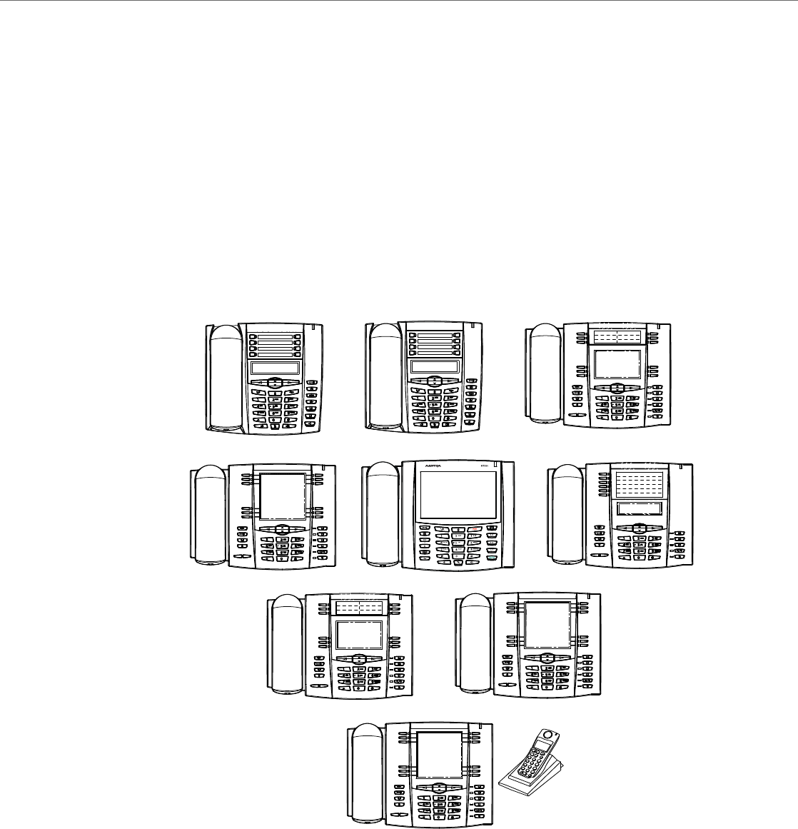
IP Phone Models
41-001343-02 REV04 – 05.2014 1-2
IP Phone Models
Description
All Aastra SIP IP Phone Models communicate over an IP network allowing you to receive and place calls in the same man-
ner as a regular business telephone.
All phone models support the Session Initiation Protocol (SIP). The 9480i CT and 6757i CT offers the base phone along
with a cordless extension.
References
For more information about the features and installation requirements, see the SIP IP Phone Installation Guide for your
specific model.
The following illustrations show the types of IP Phone Models.
6730i
6739i
6755i 6757i
6757i CT
6753i
6731i 6735i
6737i
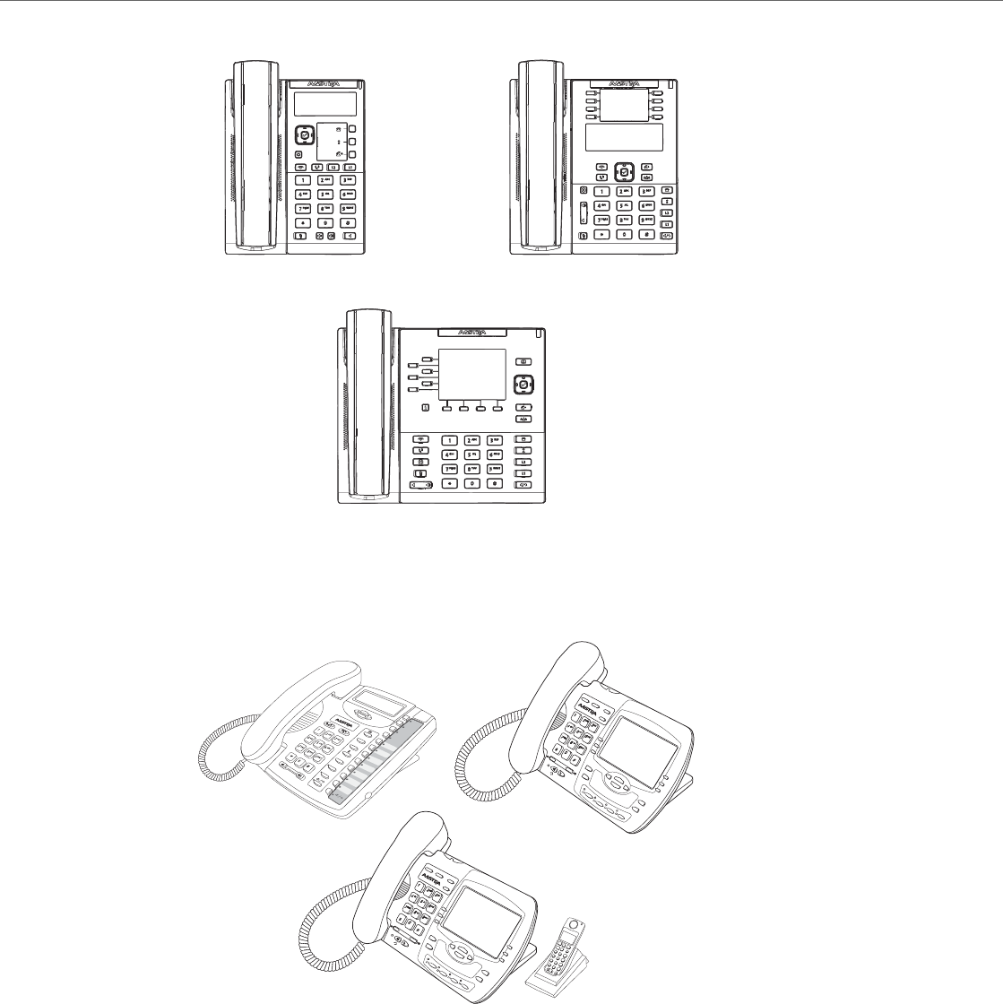
IP Phone Models
1-3 41-001343-02 REV04 – 05.2014
6865i
6867i
6863i
Options
Directory
Delete
Save
Mute
Xfer
Conf
L2
L3
L1
Conf
Services
Xfer
Icom
Hold
Redial
Goodbye
Options
9480i
Conf
Services
Xfer
Icom
Hold
Redial
Goodbye
Options
9480i CT
9480i
9480i CT
9143i
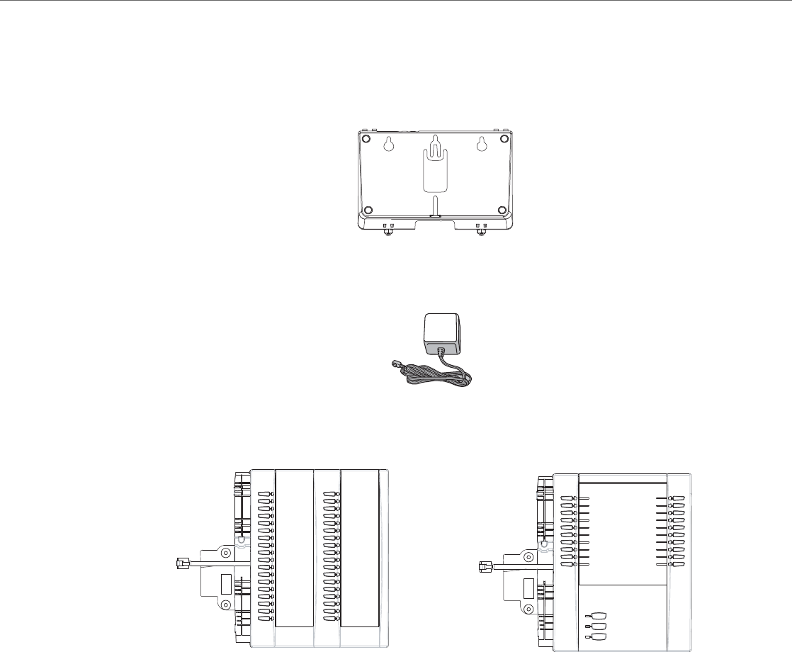
IP Phone Models
41-001343-02 REV04 – 05.2014 1-4
Optional Accessories
6700 Series
The following are optional accessories specifically for the 6700i Series IP Phones.
The following are optional accessories specifically for the 6731i, 6735i, 6737i, and 6739i IP Phones.
The following are optional accessories specifically for the 6735i, 6737i, 6739i, 6753i, 6755i, 6757i, and 6757i CT IP Phones.
The M670i module adds 36 additional softkeys to the IP phone models 6735i, 6737i, 6739i, 6753i, 6755i, 6757i, and 6757i
CT. The M670i provides paper labels for each softkey. Up to 3 modules can be daisy-chained to provide up to 108 addi-
tional softkeys for the phone when powered via the 48V AC adapter.
The M675i module adds 60 additional softkeys to the IP phone models 6735i, 6737i, 6739i, 6755i, 6757i, and 6757i CT
(using the 3 function keys on the bottom right of the unit). The M675i module provides an LCD screen for displaying
softkey labels. Up to 3 modules can be daisy-chained to provide up to 180 additional softkeys for the phone when pow-
ered via the 48V AC adapter.
Refer to the table below for additional daisy-chaining information.
6700i Wall Mount Kit
Power Adapter
M670i Expansion Module
for 6735i, 6737i, 6739i, 6753i, 6755i,
M675i Expansion Module
for 6735i, 6737i, 6739i, 6755i, 6757i,
6757i, and 6757i CT and 6757i CT

IP Phone Models
1-5 41-001343-02 REV04 – 05.2014
M670i/M675i Expansion Modules Daisy-Chaining Support
Reference
For more information about installing the 6700i Wall Mount Kit and setting up and using the expansion modules, see the
6700i Wall Mount Kit Installation Guide, your <Model-Specific> Installation Guide, as well as your <Model-Specific>
IP Phone User Guide.
IP Phone Model Maximum Number of Diasy-Chained
Modules When Powered Via 48V AC Adapter Maximum Number of Diasy-Chained
Modules When Powered Via PoE PoE Class
6730i 0 N/A No PoE Support
6731i 0 0 Class 1 (<3.84W)
6735i 3 1 Class 2 (< 6.49W)
6737i 3 1 Class 2 (< 6.49W)
6739i 3 0 Class 0 (< 12.94W)
6753i 3 3 Class 0 (< 12.94W)
6755i 3 3 Class 0 (< 12.94W)
6757i 3 3 Class 0 (< 12.94W)
6757i CT 3 3 Class 0 (< 12.94W)
Note:
Daisy-chaining M670i modules with M675i modules is supported for all IP phone models except the 6753i (the 6753i
only supports the M670i expansion module).
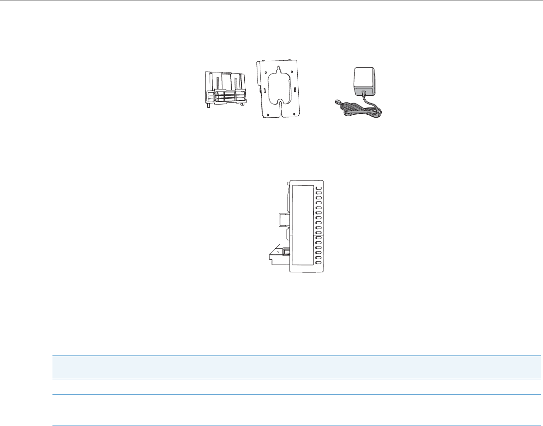
IP Phone Models
41-001343-02 REV04 – 05.2014 1-6
6800i Series
The following are optional accessories specifically for the 6800i Series IP Phones.
The following are optional accessories specifically for the 6865i and 6867i IP Phones.
The M680i module adds 16 additional softkeys to the 6865i and 6867i IP phones and provides paper labels for each
softkey. Up to 3 modules can be daisy-chained to provide up to 48 additional softkeys for the phone. No separate power
adaptor is required as the M680i is powered by the respective IP phone.
M680i Expansion Modules Daisy-Chaining Support
M680i Software Upgrades
The M680i does not require a separate firmware package. M680i software is embedded within the respective phone’s
firmware package.
When the M680i is connected and is powered up, the LED corresponding to the second button on the module will turn
solid red and the module will check to see if an upgrade is required. If it does not have the latest software, the module will
upgrade itself using the phone’s embedded firmware. This process will take approximately 10 seconds, in which case the
LED corresponding to the second button on the M680i will stay solid red for the duration. If the upgrade is successful, the
LED will turn green. If the LED stays solid and red for longer than 10 seconds, the upgrade may have failed. In such scenar-
ios, unplug and reattach the power source from the phone to attempt the upgrade again.
As software upgrades are performed one at a time, each additional M680i connected increases the approximate upgrade
time by 10 seconds (e.g. three connected M680i expansion modules will take approximately 30 seconds to upgrade).
Reference
For more information about installing the 6800i Wall Mount Kit and setting up and using the M680i expansion module, see
the 6800i Wall Mount Kit Installation Guide, the M680i Expansion Module Installation Guide, M680i Expansion
Module Quick Start Guide, your <Model-Specific> Installation Guide, as well as your <Model-Specific> IP Phone User
Guide.
IP Phone Model Maximum Number of Diasy-Chained
Modules When Powered Via 48V AC Adapter Maximum Number of Diasy-Chained
Modules When Powered Via PoE PoE Class
6865i 3 3 Class 2 (< 6.49W)
6867i 3 3 Class 2 (< 6.49W) without modules.
Dynamically switches to Class 3
(< 12.95W) when modules are attached.
6800i Wall Mount Kit Power Adapter
M680i Expansion Module

IP Phone Models
1-7 41-001343-02 REV04 – 05.2014
Model 6730i IP Phone
This section provides brief information about the Model 6730i IP Phone. It includes a list of features and describes the
hard keys on the 6730i. The 6730i is available with a symbol keypad or a text keypad.
6730i Phone Features (Symbol and Text)
•3-line LCD screen
•8 programmable top keys
•Press-and-hold speed dial key configuration feature
•Supports up to 6 call lines with LEDs
•Full-duplex speakerphone for handsfree calls
•Headset mode support (via handset jack)
•AC power adapter (included)
•Enhanced busy lamp fields*
•Set paging*
*Availability of feature dependant on your phone system or service provider.
6730i with Symbol or Text Keys
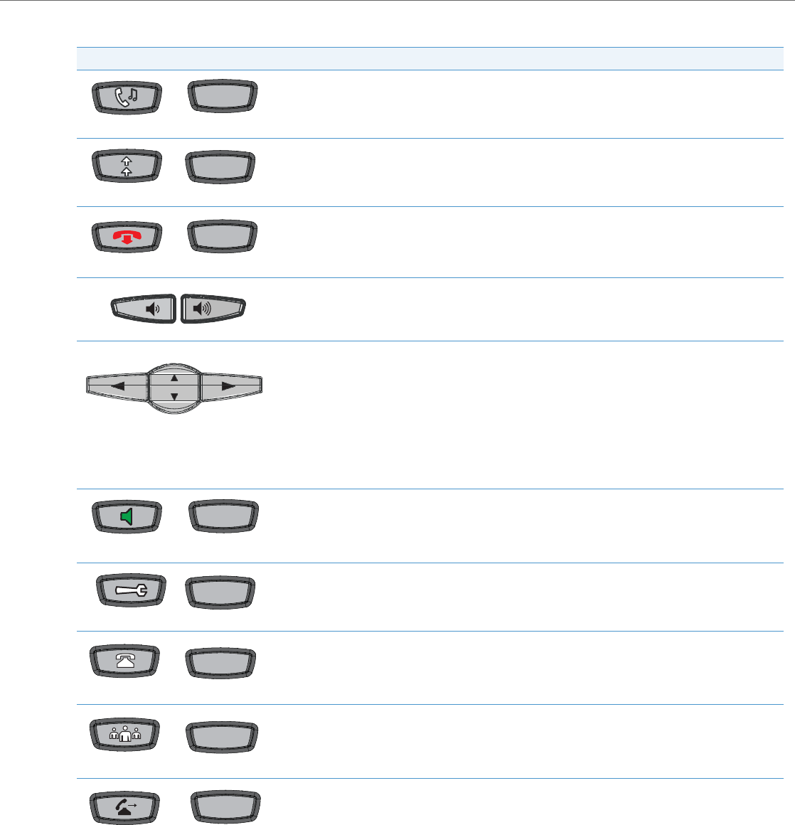
IP Phone Models
41-001343-02 REV04 – 05.2014 1-8
6730i Symbol and Text Key Descriptions*
Symbol Keys Text Keys Key Description
Hold key - Places an active call on hold. To retrieve a held call, press the call appearance button beside the
light that is flashing.
Redial key - Redials up to 100 previously dialed numbers. Pressing the Redial key twice redials the last dialed
number.
Goodbye key - Ends an active call. The Goodbye key also exits an open list, such as the Options List, without
saving changes.
Volume control key - Adjusts the volume for the handset, ringer, and handsfree speaker.
Navigation keys - Pressing the UP and DOWN arrow keys lets you view different status and text messages on
the LCD display (if there is more than 1 line of status/text messages). These keys also let you scroll through
menu selections, such as the Options List, and scroll through a remote number that is displayed on the
phone. Users can press the scrolling DOWN navigation key to view the rest of the phone number content.
Pressing the LEFT and RIGHT arrow keys lets you view the different line/call appearances. While in the Options
List, these keys allow you to exit or enter the current option.
When you are editing entries on the display, pressing the LEFT arrow key works as a backspace instead of a
moving cursor. the LEFT arrow key erases the digit/character at the cursor location including the dot/decimal.
The RIGHT arrow key sets the option.
Speaker key - Transfers the active call to the speaker, allowing handsfree use of the phone. Switched
between headset and speaker depending on audio mode setting.
Options key - Accesses services and options to customize your phone. Your System Administrator may have
already customized some of your settings.
Callers List key - Accesses the last 200 calls received.
Conference key - Begins a conference call with the active call.
Transfer key - Transfers the active call to another number.
Hold
Redial
Goodbye
Speaker
OptionsOptions
Callers
Conf
Transfer
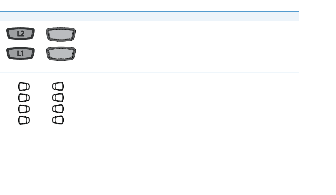
IP Phone Models
1-9 41-001343-02 REV04 – 05.2014
*See the Aastra Model 6730i IP Phone User Guide for more information about each of these keys.
Line/Call Appearance keys - Connect you to a line or call. The Aastra 6730i IP phone supports 2 line keys,
each with LED indicator lights. Additional lines (up to 6 in total) can be added to the programmable keys.
Programmable keys - 8 Top Keys - all 8 keys are programmable.
Keys 5 and 6 are designated as the SAVE and DELETE keys, respectively. These keys must be made configura-
ble by the System Administrator before they can be changed.
The following are the default functions for the programmable keys on the 6730i IP phone:
1 - None
2 - None
3 - None
4 - None
5 - SAVE - Allows you to save numbers (preconfigured) and/or names to the Directory. Using this key, you
enter the number, name, and line (or speed dial key) to record in the Directory List.
6 - DELETE - Allows you to delete entries (preconfigured) from the Directory List and Callers List. (Must enter
the Directory or Callers list and select an entry, then press twice to delete entry).
7 - DIRECTORY - Displays up to 200 names (preconfigured) and phone numbers (stored in alphabetical order)
8 - SERVICES - Accesses enhanced features (preconfigured) and services through the Services menu.
Note:
For more information about configuring the programmable keys 1 through 8 to perform specific functions,
see Chapter 5, “Configuring Operational Features” the section, “Softkeys/Programmable Keys/Feature
Keys/Expansion Module Keys” on page5-104.
Symbol Keys Text Keys Key Description
Line 1Line 1
Line 2Line 2
1
2
3
4
5
6
7
8

IP Phone Models
41-001343-02 REV04 – 05.2014 1-10
Model 6731i IP Phone
This section provides brief information about the Model 6731i IP Phone. It includes a list of features and describes the hard
keys on the 6731i. The 6731i is available with a symbol keypad or a text keypad.
6731i Phone Features (Symbol and Text)
•3-line LCD screen
•8 programmable top keys
•Press-and-hold speed dial key configuration feature
•Supports up to 6 call lines with LEDs
•Full-duplex speakerphone for handsfree calls
•Headset mode support (via handset jack)
•Built-in two-port, 10/100 Ethernet ports - lets you share a connection with your computer
•Inline power support (based on 802.3af standard) which eliminates power adapters
•AC power adapter (optional equipment - not included)
•Enhanced busy lamp fields*
•Set paging*
*Availability of feature dependant on your phone system or service provider.
6731i with Symbol or Text Keys
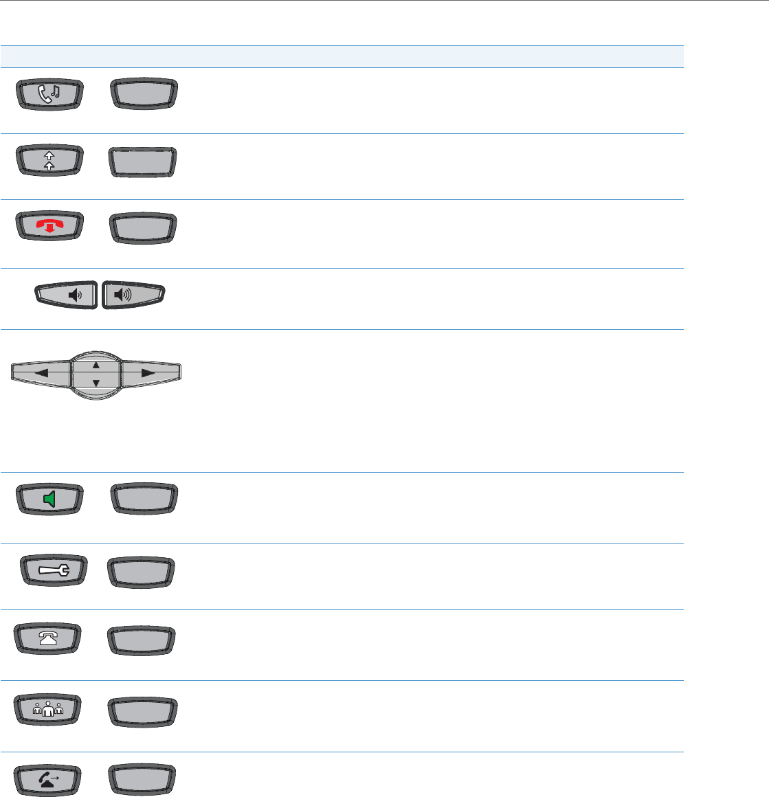
IP Phone Models
1-11 41-001343-02 REV04 – 05.2014
6731i Symbol and Text Key Descriptions*
Symbol Keys Text Keys Key Description
Hold key - Places an active call on hold. To retrieve a held call, press the call appearance button beside the
light that is flashing.
Redial key - Redials up to 100 previously dialed numbers. Pressing the Redial key twice redials the last dialed
number.
Goodbye key - Ends an active call. The Goodbye key also exits an open list, such as the Options List, without
saving changes.
Volume control key - Adjusts the volume for the handset, ringer, and handsfree speaker.
Navigation keys - Pressing the UP and DOWN arrow keys lets you view different status and text messages on
the LCD display (if there is more than 1 line of status/text messages). These keys also let you scroll through
menu selections, such as the Options List, and scroll through a remote number that is displayed on the
phone. Users can press the scrolling DOWN navigation key to view the rest of the phone number content.
Pressing the LEFT and RIGHT arrow keys lets you view the different line/call appearances. While in the
Options List, these keys allow you to exit or enter the current option.
When you are editing entries on the display, pressing the LEFT arrow key works as a backspace instead of a
moving cursor. the LEFT arrow key erases the digit/character at the cursor location including the dot/deci-
mal. The RIGHT arrow key sets the option.
Speaker key - Transfers the active call to the speaker, allowing handsfree use of the phone. Switched
between headset and speaker depending on audio mode setting.
Options key - Accesses services and options to customize your phone. Your System Administrator may have
already customized some of your settings.
Callers List key - Accesses the last 200 calls received.
Conference key - Begins a conference call with the active call.
Transfer key - Transfers the active call to another number.
Hold
Redial
Redial
Goodbye
Speaker
Options
Options
Callers
Conf
Transfer
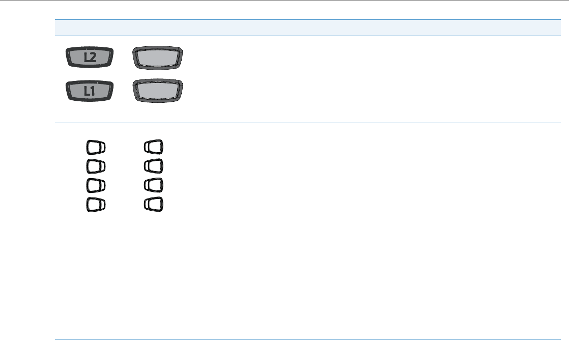
IP Phone Models
41-001343-02 REV04 – 05.2014 1-12
*See the Aastra Model 6731i IP Phone User Guide for more information about each of these keys.
Line/Call Appearance keys - Connect you to a line or call. The Aastra 6731i IP phone supports 2 line keys,
each with LED indicator lights. Additional lines (up to 6 in total) can be added to the programmable keys.
Programmable keys - 8 Top Keys - all 8 keys are programmable.
Keys 5 and 6 are designated as the SAVE and DELETE keys, respectively. These keys must be made configura-
ble by the System Administrator before they can be changed.
The following are the default functions for the programmable keys on the 6731i IP phone:
1 - None
2 - None
3 - None
4 - None
5 - SAVE - Allows you to save numbers (preconfigured) and/or names to the Directory. Using this key, you
enter the number, name, and line (or speed dial key) to record in the Directory List.
6 - DELETE - Allows you to delete entries (preconfigured) from the Directory List and Callers List. (Must enter
the Directory or Callers list and select an entry, then press twice to delete entry).
7 - DIRECTORY - Displays up to 200 names (preconfigured) and phone numbers (stored in alphabetical
order)
8 - SERVICES - Accesses enhanced features (preconfigured) and services through the Services menu.
Note:
For more information about configuring the programmable keys 1 through 8 to perform specific functions,
see Chapter 5, “Configuring Operational Features” the section, “Softkeys/Programmable Keys/Feature
Keys/Expansion Module Keys” on page5-104.
Symbol Keys Text Keys Key Description
Line 1Line 1
Line 2Line 2
1
2
3
4
5
6
7
8

IP Phone Models
1-13 41-001343-02 REV04 – 05.2014
Model 6735i IP Phone
This section provides brief information about the Model 6735i IP Phone. It includes a list of features, and describes the
hard keys, default programmable keys, and default softkeys on the 6735i. The 6735i is available with a symbol keypad or
a text keypad.
6735i Phone Features (Symbol and Text)
•8-line graphical LCD screen (144 x 75 pixels) with white backlight
•12 programmable keys
–6 programmable hard keys on the top
–6 programmable state-based softkeys on the bottom
•4 call appearance lines with LEDs
•Press-and-Hold speed dial key configuration feature
•Supports up to 9 call lines
•Full-duplex speakerphone for handsfree calls
•Headset support (modular connector)
•Built-in-two-port, 10/100/1000 Ethernet switch - lets you share a connection with your computer.
•Inline power support (based on 802.3af standard) which eliminates power adapters.
•Enhanced busy lamp fields*
•Set paging*
*Availability of feature dependant on your phone system or service provider.
6735i with Symbol or Text Keys
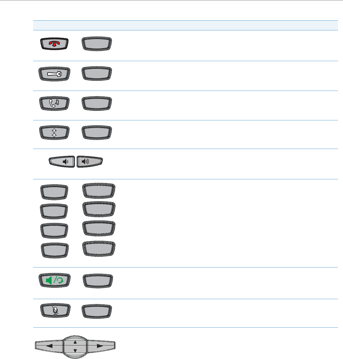
IP Phone Models
41-001343-02 REV04 – 05.2014 1-14
6735i Symbol and Text Key Descriptions*
Symbol Keys Text Keys Key Description
Goodbye key - Ends an active call. The Goodbye key also exits an open list, such as the Options List, without
saving changes.
Options key - Accesses options to customize your phone. Your System Administrator may have already cus-
tomized some of your settings. Check with your System Administrator before changing the administrator-
only options.
Hold key - Places an active call on hold. To retrieve a held call, press the call appearance button beside the
light that is flashing.
Redial key - Redials up to 100 previously dialed numbers. Pressing the Redial key twice simultaneously redi-
als the last dialed number.
Volume control key - Adjusts the volume for the handset, headset, ringer, and handsfree speaker.
Line/Call Appearance key - Connects you to a line or call. The Aastra 6735i IP phone supports up to 4 line
keys.
Handsfree key - Activates Handsfree for making and receiving calls without lifting the handset. When the
audio mode option is set, this key is used to switch between a headset and the handsfree speakerphone.
Mute key - Mutes the microphone so that your caller cannot hear you (the light indicator flashes when the
microphone is on mute).
Navigation keys - Pressing the UP and DOWN arrow keys lets you view different status and text messages
on the LCD display (if there is more than 1 line of status/text messages). These keys also let you scroll
through menu selections, such as the Options List, and scroll through a remote number that is displayed on
the phone. Users can press the scrolling DOWN navigation key to view the rest of the phone number con-
tent.
Pressing the LEFT and RIGHT arrow keys lets you view the different line/call appearances. While in the
Options List, these keys allow you to exit or enter the current option. When you are editing entries on the dis-
play, pressing the LEFT arrow key erases the character on the left; pressing the RIGHT arrow key sets the
option.
Goodbye
OptionsOptions
Hold
Redial
L1L1
L2L2
L3L3
L4L4
Line 1
Line 1
Line 2
Line 2
Line 3
Line 3
Line 4
Line 4
Speaker/
Headset
Mute

IP Phone Models
1-15 41-001343-02 REV04 – 05.2014
*See the Aastra Model 6735i IP Phone User Guide for more information about each of these keys.
Programmable keys - 6 Top keys: programmable hard keys (up to 6 programmable functions)
By default, the top keys 1 through 4 are assigned as Services, Directory, Callers List, and Intercom, respec-
tively. Keys 5 and 6 have no assigned functions. All 6 keys are programmable and can be assigned to perform
specific functions.
The following are the default functions for the programmable keys on the 6735i IP phone:
1 - SERVICES -Accesses enhanced features and services such as XML applications and voicemail, provided
by third parties.
2 - DIRECTORY- Displays up to 200 names and phone numbers (stored in alphabetical order).
3 - CALLERS LIST - Accesses the last 200 calls received.
4 - ICOM - Accesses another extension on the network.
5 - None
6 - None
Note:
For more information about configuring the programmable keys 1 through 6 to perform specific functions,
see Chapter 5, “Configuring Operational Features” the section, “Softkeys/Programmable Keys/Feature
Keys/Expansion Module Keys” on page5-104.
Softkeys - 6 Bottom keys: programmable state-based softkeys (up to 20 programmable functions).
By default, the bottom softkeys 2 through 6 have no assigned functions. You can configure all 6 bottom
softkeys to perform specific functions on the 6735i IP phone. However, after you lift the handset, there are
specific static softkeys that display that cannot be changed. These are as follows:
1 - DIAL - Allows you to dial out on the phone.
2 - CONF - Begins a conference call with the active phone.
3 - XFER - Transfers the active call to another number.
Note:
For more information about configuring softkeys 1 through 6 to perform specific functions, see Chapter 5,
“Configuring Operational Features” the section, “Softkeys/Programmable Keys/Feature Keys/Expansion
Module Keys” on page5-104.
Symbol Keys Text Keys Key Description
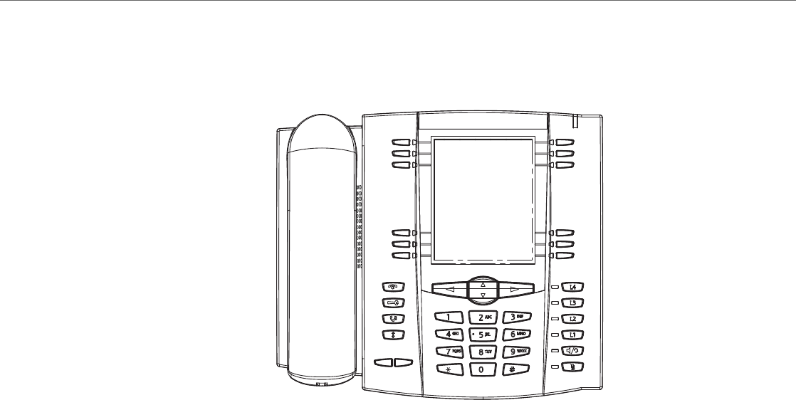
IP Phone Models
41-001343-02 REV04 – 05.2014 1-16
Model 6737i IP Phone
This section provides brief information about the 6737i IP Phone. It includes a list of features, and describes the hard keys
and default softkeys on the 6737i. The 6737i is available with a symbol keypad or a text keypad.
6737i Phone Features (Symbol and Text)
•11-line graphical LCD screen (144 x 128 pixels) with white backlight
•12 multi-functional softkeys
–6 Top Keys: programmable static softkeys
–6 Bottom Keys: programmable state-based softkeys
•4 call appearance lines with LEDs
•Press-and-Hold speed dial key configuration feature
•Supports up to 9 call lines
•Full-duplex speakerphone for handsfree calls
•Headset support (modular connector)
•Built-in-two-port, 10/100/1000 Ethernet switch - lets you share a connection with your computer.
•Inline power support (based on 802.3af standard) which eliminates power adapters.
•Enhanced busy lamp fields*
•Set paging*
*Availability of feature dependant on your phone system or service provider.
6737i with Symbol or Text Keys
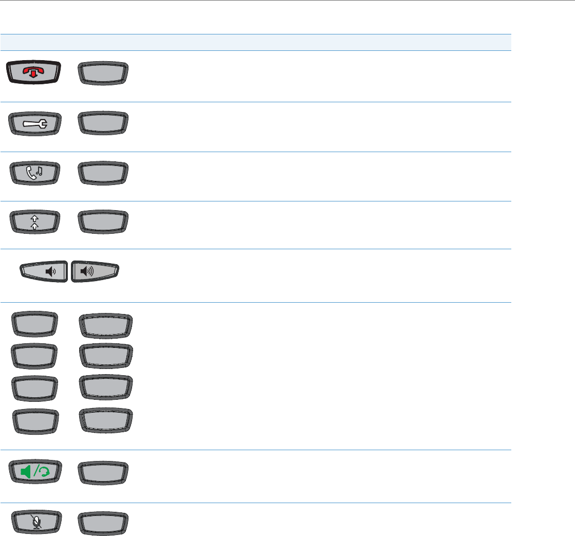
IP Phone Models
1-17 41-001343-02 REV04 – 05.2014
6737i Symbol and Text Key Descriptions*
Symbol Keys Text Keys Key Description
Goodbye key - Ends an active call. The Goodbye key also exits an open list, such as the Options List, without
saving changes.
Options key - Accesses options to customize your phone. Your System Administrator may have already cus-
tomized some of your settings. Check with your System Administrator before changing the administrator-
only options.
Hold key - Places an active call on hold. To retrieve a held call, press the call appearance button beside the
light that is flashing.
Redial key - Redials up to 100 previously dialed numbers. Pressing the Redial key twice simultaneously redials
the last dialed number.
Volume control key - Adjusts the volume for the handset, headset, ringer, and handsfree speaker.
Line/Call Appearance key - Connects you to a line or call. The Aastra 6737i IP phone supports up to 4 line
keys.
Handsfree key - Activates Handsfree for making and receiving calls without lifting the handset. When the
audio mode option is set, this key is used to switch between a headset and the handsfree speakerphone.
Mute key - Mutes the microphone so that your caller cannot hear you (the light indicator flashes when the
microphone is on mute).
Goodbye
OptionsOptions
Hold
Redial
L1L1
L2L2
L3L3
L4L4
Line 1
Line 1
Line 2
Line 2
Line 3
Line 3
Line 4
Line 4
Speaker/
Headset
Mute
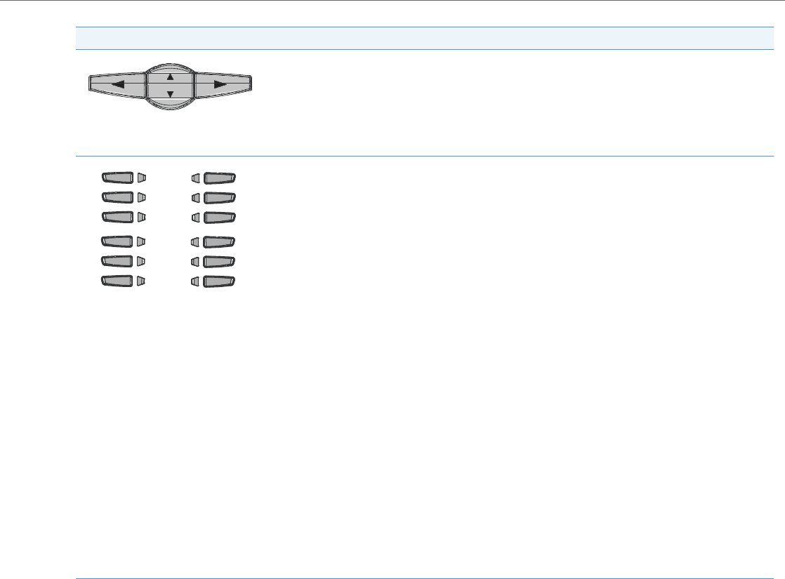
IP Phone Models
41-001343-02 REV04 – 05.2014 1-18
*See the Aastra Model 6737i IP Phone User Guide for more information about each of these keys.
Navigation keys - Pressing the UP and DOWN arrow keys lets you view different status and text messages on
the LCD display (if there is more than 1 line of status/text messages). These keys also let you scroll through
menu selections, such as the Options List, and scroll through a remote number that is displayed on the phone.
Users can press the scrolling DOWN navigation key to view the rest of the phone number content.
Pressing the LEFT and RIGHT arrow keys lets you view the different line/call appearances. While in the Options
List, these keys allow you to exit or enter the current option. When you are editing entries on the display,
pressing the LEFT arrow key erases the character on the left; pressing the RIGHT arrow key sets the option.
Softkeys - 12 softkeys on the 6737i IP Phone.
•6 Top Keys: programmable static softkeys (up to 10 programmable functions)
•6 Bottom Keys: programmable state-based softkeys (up to 20 programmable functions)
By default, the top softkeys 1 through 4 are assigned as Services, Directory, Callers List, and Intercom, respec-
tively. Keys 5 and 6 have no assigned functions. All 6 keys are programmable and can be assigned to perform
specific functions.
The following are the default functions for the top softkeys on the 6737i IP phone:
1 - SERVICES - Accesses enhanced features and services such as XML applications and voicemail, provided by
third parties.
2 - DIRECTORY - Displays up to 200 names and phone numbers (stored in alphabetical order).
3 - CALLERS LIST - Accesses the last 200 calls received.
4 - ICOM - Accesses another extension on the network.
5 - None
6 - None
7 - None
By default, the bottom softkeys 8 through 12 have no assigned functions. You can configure all 6 bottom
softkeys to perform specific functions on the 6737i IP phone. However, after you lift the handset, there are
specific static softkeys that display that cannot be changed. These are as follows:
7- DIAL - Allows you to dial out on the phone.
8- CONF - Begins a conference call with the active phone.
9- XFER - Transfers the active call to another number.
Note:
For more information about programming the softkeys to perform specific functions, see Chapter 5, “Config-
uring Operational Features” the section, “Softkeys/Programmable Keys/Feature Keys/Expansion Module
Keys” on page5-104.
Symbol Keys Text Keys Key Description

IP Phone Models
1-19 41-001343-02 REV04 – 05.2014
Model 6739i IP Phone
This section provides brief information about the Model 6391i IP Phone. It includes a list of features and describes the
hard keys on the 6739i. The 6739i is available with a symbol keypad or a text keypad.
6739i Phone Features (Symbol and Text)
•Large 5.7” full VGA (640x480) color touch screen display and backlight
•Advanced and expandable Executive Level SIP Phone
•Intuitive graphical user interface and navigation menus
•Two built-in 10/100/1000 Gigabit Ethernet switch ports - lets you share a connection with your computer.
•Inline power support (based on 802.3af Power-over-Ethernet (PoE) standard) which eliminates power adapters
•Built-in Bluetooth technology for headset support
•Existing 675xi Expansion Module support
•USB port support (for future use)
•Aastra Hi-Q Audio™ Technology
•Full-duplex speakerphone for handsfree calls
•Additional headset connection options: modular RJ jack, built-in EHS/DHSG port (refer to the IP Phone 6739i Installa-
tion Guide for information on installing a DHSG headset on your phone.)
•Up to 9 lines with 3 call appearance lines with multi-proxy support
•Up to 55 programmable softkeys
•Picture ID feature (during calls and in the Directory, Callers List, and Redial List)
•XML support for productivity-enhancing applications
•AC power adapter (sold separately)
6739i with Symbol or Text Keys
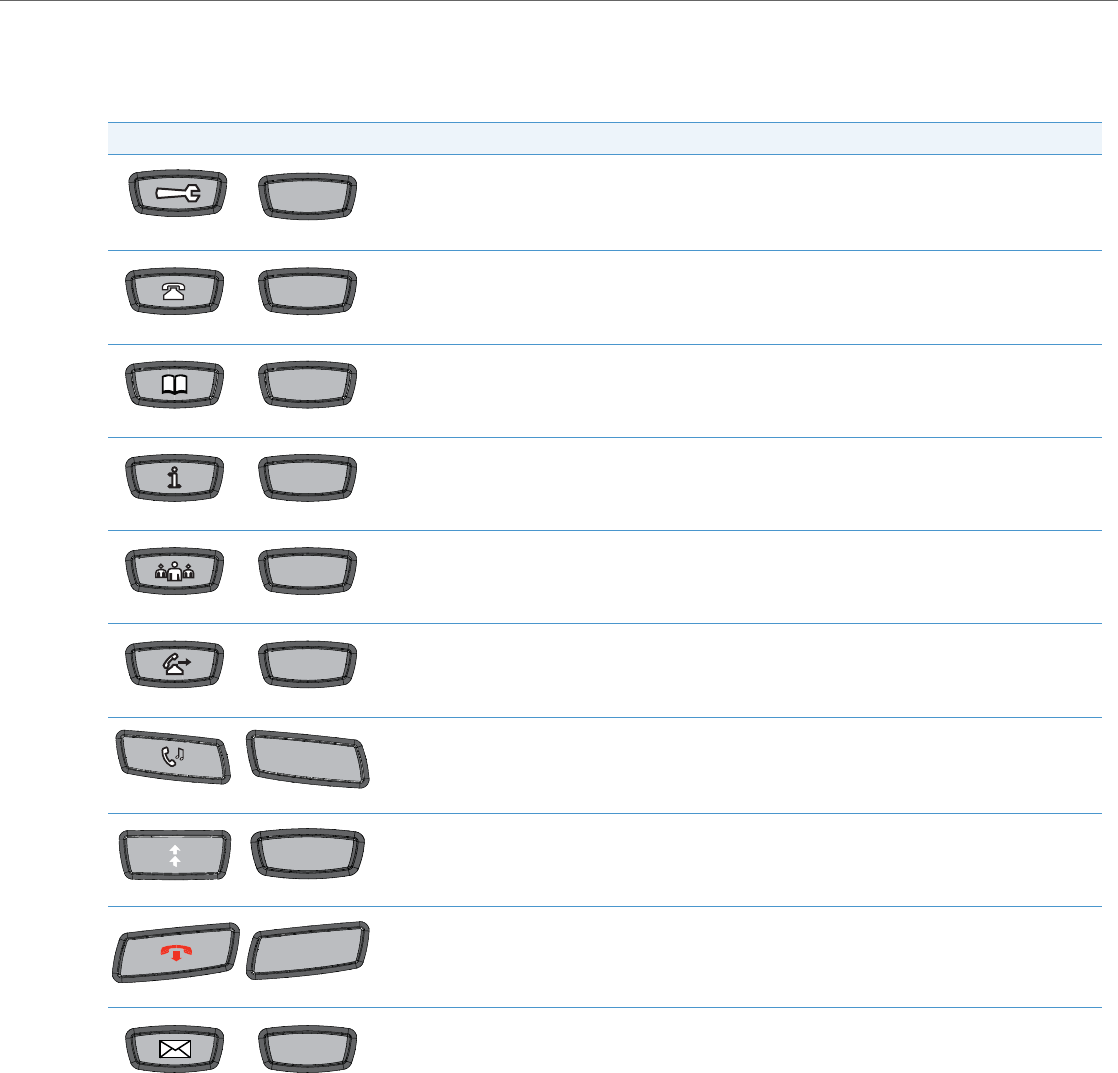
IP Phone Models
41-001343-02 REV04 – 05.2014 1-20
6739i Symbol and Text Key Descriptions*
The following table identifies the keys on the key panel of your 6739i IP phone that you can use for handling calls. Your
phone may contain symbol keys or text keys, depending on which Model 6739i phone you purchased.
Symbol Keys Text Keys Key Description
Options Key - Accesses options to customize your phone. Your System Administrator may have already cus-
tomized some of your settings. Check with your System Administrator before changing the administrator-
only options.
Callers List Key - Accesses a list of calls received by the phone.
Directory Key - Accesses a directory of names and phone numbers (stored in alphabetical order).
Services Key - Accesses enhanced features and services set up by your System Administrator.
Conference Key - Begins a conference call with the active call.
Transfer Key - Transfers the active call to another number.
Hold Key - Places an active call on hold. To retrieve a held call, press the call appearance button beside the
light that is flashing or press the Hold key again.
Redial Key - Redials previously dialed numbers. Also accesses a Redial List of up to 100 stored numbers that
called your phone.
Goodbye Key - Ends an active call. The Goodbye key also exits an open list, such as the Options List.
Messages Key - Accesses your phone’s voice mailbox to retrieve and listen to stored messages.
Options
Options
Callers
Callers
Directory
Directory
Services
Services
Conf
Conf
Transfer
Transfer
Hold
Hold
Redial
GoodbyeGoodbye
Messages
Messages
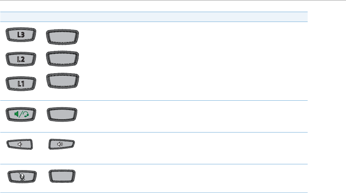
IP Phone Models
1-21 41-001343-02 REV04 – 05.2014
*See the Aastra Model 6739i IP Phone User Guide for more information about each of these keys.
Line/Call Appearance Keys - Connect you to a line or call. The Aastra 6739i IP phone supports 3 line call
appearance keys.
Speakerphone/Headset Key - Activates handsfree for making and receiving calls without lifting the handset.
When the audio mode option is set, this key is used to switch between a headset and the handsfree speaker-
phone.
Volume Control Key - Adjusts the volume for the handset, headset, ringer, and handsfree speaker.
Mute key - Mutes the microphone so that your caller cannot hear you (the light indicator flashes when the
microphone is on mute).
Symbol Keys Text Keys Key Description
Line 1
Line 1
Line 2
Line 2
Line 3
Line 3
Speaker/Speaker/
HeadsetHeadset
MuteMute
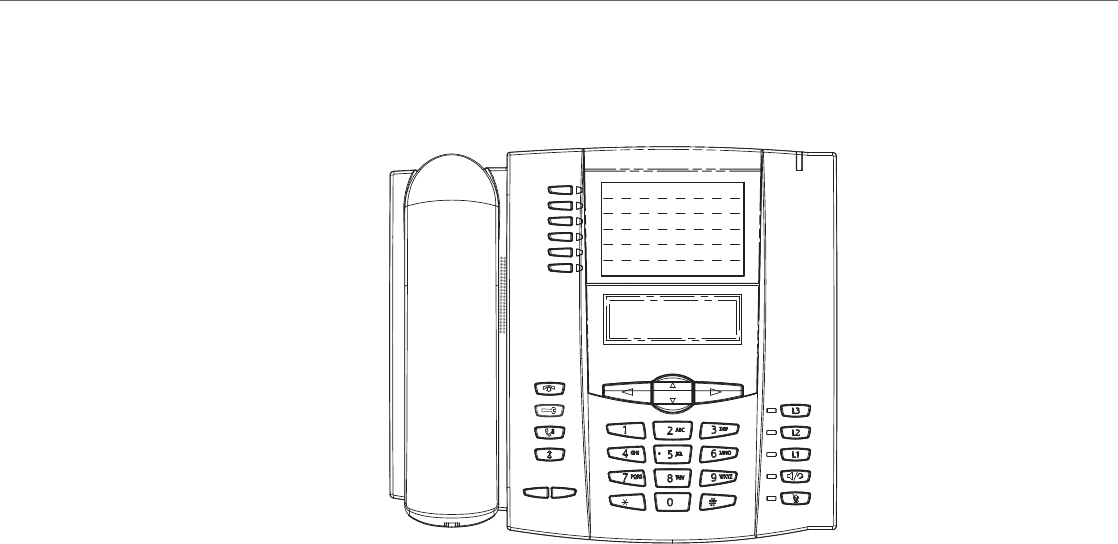
IP Phone Models
41-001343-02 REV04 – 05.2014 1-22
Model 6753i IP Phone
This section provides brief information about the Model 6753i IP Phone. It includes a list of features, and describes the
hard keys and default programmable keys on the 6753i. The 6753i is available with a symbol keypad or a text keypad.
6753i Phone Features (Symbol and Text)
•3-line LCD screen
•6 programmable top keys
•3 call appearance lines with LEDs
•Press-and-Hold speed dial key configuration feature
•Supports up to 9 call lines
•Full-duplex speakerphone for handsfree calls
•Headset support (modular connector)
•Built-in two-port, 10/100 Ethernet ports - lets you share a connection with your computer
•Inline power support (based on 802.3af standard) which eliminates power adapters.
•AC power adapter (included)
•Enhanced busy lamp fields*
•Set paging*
*Availability of feature dependant on your phone system or service provider.
6753i with Symbol or Text Keys
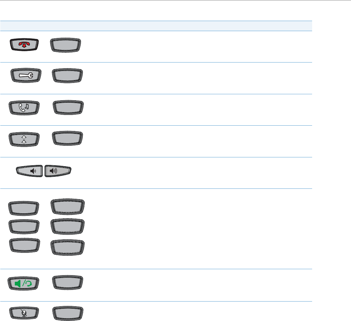
IP Phone Models
1-23 41-001343-02 REV04 – 05.2014
6753i Symbol and Text Key Descriptions*
Symbol Keys Text Keys Key Description
Goodbye key - Ends an active call. The Goodbye key also exits an open list, such as the Options List, without
saving changes.
Options key - Accesses options to customize your phone. Your System Administrator may have already cus-
tomized some of your settings. Check with your System Administrator before changing the administrator-
only options.
Hold key - Places an active call on hold. To retrieve a held call, press the call appearance button beside the
light that is flashing.
Redial key - Redials up to 100 previously dialed numbers. Pressing the Redial key twice simultaneously redi-
als the last dialed number.
Volume control key - Adjusts the volume for the handset, headset, ringer, and handsfree speaker.
Line/Call Appearance key - Connects you to a line or call. The Aastra 6753i IP phone supports up to 3 line
keys.
Handsfree key - Activates Handsfree for making and receiving calls without lifting the handset. When the
audio mode option is set, this key is used to switch between a headset and the handsfree speakerphone.
Mute key - Mutes the microphone so that your caller cannot hear you (the light indicator flashes when the
microphone is on mute).
Goodbye
OptionsOptions
Hold
Redial
L1L1
L2L2
L3L3
Line 1
Line 1
Line 2
Line 2
Line 3
Line 3
Speaker
Mute

IP Phone Models
41-001343-02 REV04 – 05.2014 1-24
*See the Aastra Model 6753i IP Phone User Guide for more information about each of these keys.
Navigation keys - Pressing the UP and DOWN arrow keys lets you view different status and text messages
on the LCD display (if there is more than 1 line of status/text messages). These keys also let you scroll through
menu selections, such as the Options List, and scroll through a remote number that is displayed on the
phone. Users can press the scrolling DOWN navigation key to view the rest of the phone number content.
Pressing the LEFT and RIGHT arrow keys lets you view the different line/call appearances. While in the
Options List, these keys allow you to exit or enter the current option.
When you are editing entries on the display, pressing the LEFT arrow key works as a backspace instead of a
moving cursor. the LEFT arrow key erases the digit/character at the cursor location including the dot/deci-
mal. The RIGHT arrow key sets the option.
Programmable keys - 6 Top Keys - all 6 keys are programmable.
Keys 1 and 2 are designated as the SAVE and DELETE keys, respectively. These keys are locked but can be
unlocked and made configurable if required by the System Administrator.
The following are the default functions for the programmable keys on the 6753i IP phone:
1 - SAVE - Allows you to save numbers and/or names to theDirectory. Using this key, you enter the number,
name, and line (or speed dial key) to record in the Directory List.
2 - DELETE - Allows you to delete a single entry or all entries fromthe Directory List and Callers List.
3 - DIRECTORY - Displays up to 200 names and phone numbers (stored in alphabetical order).
4 - CALLERS LIST - Accesses the last 200 calls received.
5 - TRANSFER - Transfers the active call to another number.
6 - CONFERENCE - Begins a conference call with the active call.
Notes:
•For more information about programming the SAVE and DELETE keys, see “Locking/Unlocking the SAVE
and DELETE keys” on page5-51.
•For more information about configuring keys 1 through 6 to perform specific functions, see Chapter 5,
“Configuring Operational Features” the section, “Softkeys/Programmable Keys/Feature Keys/Expansion
Module Keys” on page5-104.
Symbol Keys Text Keys Key Description

IP Phone Models
1-25 41-001343-02 REV04 – 05.2014
Model 6755i IP Phone
This section provides brief information about the Model 6755i IP Phone. It includes a list of features, and describes the
hard keys, default programmable keys, and default softkeys on the 6755i. The 6755i is available with a symbol keypad or
a text keypad.
6755i Phone Features (Symbol and Text)
•8-line graphical LCD screen (144 x 75 pixels) with white backlight
•12 programmable keys
–6 programmable hard keys on the top
–6 programmable state-based softkeys on the bottom
•4 call appearance lines with LEDs
•Press-and-Hold speed dial key configuration feature
•Supports up to 9 call lines
•Full-duplex speakerphone for handsfree calls
•Headset support (modular connector)
•Built-in-two-port, 10/100 Ethernet switch - lets you share a connection with your computer.
•Inline power support (based on 802.3af standard) which eliminates power adapters.
•AC power adapter (included)
•Enhanced busy lamp fields*
•Set paging*
*Availability of feature dependant on your phone system or service provider.
6755i with Symbol or Text Keys
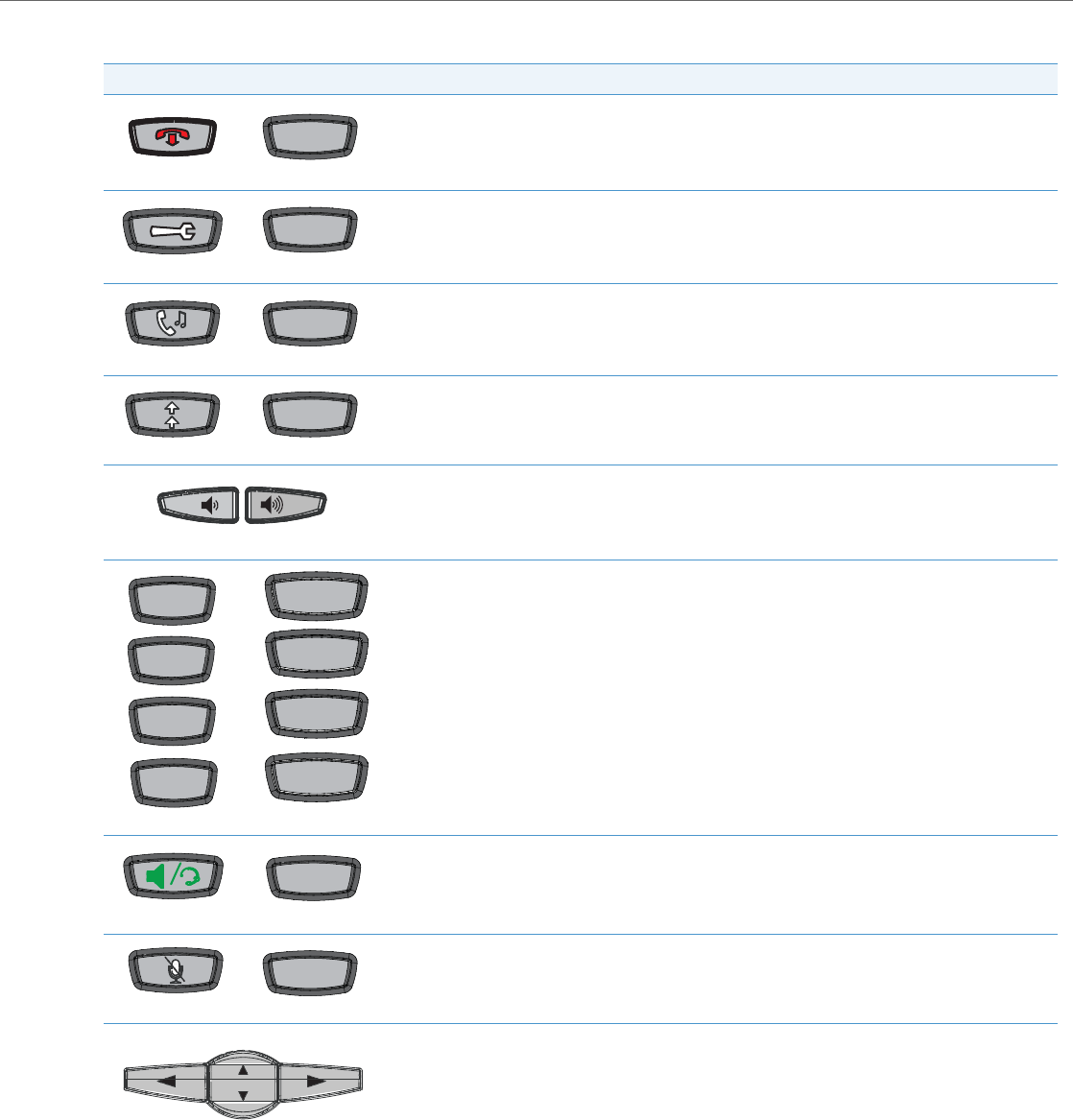
IP Phone Models
41-001343-02 REV04 – 05.2014 1-26
6755i Symbol and Text Key Descriptions*
Symbol Keys Text Keys Key Description
Goodbye key - Ends an active call. The Goodbye key also exits an open list, such as the Options List, with-
out saving changes.
Options key - Accesses options to customize your phone. Your System Administrator may have already
customized some of your settings. Check with your System Administrator before changing the administra-
tor-only options.
Hold key - Places an active call on hold. To retrieve a held call, press the call appearance button beside the
light that is flashing.
Redial key - Redials up to 100 previously dialed numbers. Pressing the Redial key twice simultaneously
redials the last dialed number.
Volume control key - Adjusts the volume for the handset, headset, ringer, and handsfree speaker.
Line/Call Appearance key - Connects you to a line or call. The Aastra 6755i IP phone supports up to 4 line
keys.
Handsfree key - Activates Handsfree for making and receiving calls without lifting the handset. When the
audio mode option is set, this key is used to switch between a headset and the handsfree speakerphone.
Mute key - Mutes the microphone so that your caller cannot hear you (the light indicator flashes when the
microphone is on mute).
Navigation keys - Pressing the UP and DOWN arrow keys lets you view different status and text messages
on the LCD display (if there is more than 1 line of status/text messages). These keys also let you scroll
through menu selections, such as the Options List, and scroll through a remote number that is displayed
on the phone. Users can press the scrolling DOWN navigation key to view the rest of the phone number
content.
Pressing the LEFT and RIGHT arrow keys lets you view the different line/call appearances. While in the
Options List, these keys allow you to exit or enter the current option. When you are editing entries on the
display, pressing the LEFT arrow key erases the character on the left; pressing the RIGHT arrow key sets the
option.
Goodbye
OptionsOptions
Hold
Redial
L1
L1
L2
L2
L3
L3
L4
L4
Line 1Line 1
Line 2Line 2
Line 3Line 3
Line 4Line 4
Speaker/
Headset
Mute

IP Phone Models
1-27 41-001343-02 REV04 – 05.2014
*See the Aastra Model 6755i IP Phone User Guide for more information about each of these keys.
Programmable keys - 6 Top keys: programmable hard keys (up to 6 programmable functions)
By default, the top keys 1 through 4 are assigned as Services, Directory, Callers List, and Intercom, respec-
tively. Keys 5 and 6 have no assigned functions. All 6 keys are programmable and can be assigned to per-
form specific functions.
The following are the default functions for the programmable keys on the 6755i IP phone:
1 - SERVICES - Accesses enhanced features and services such as XML applications and voicemail, provided
by third parties.
2 - DIRECTORY - Displays up to 200 names and phone numbers (stored in alphabetical order).
3 - CALLERS LIST - Accesses the last 200 calls received.
4 - ICOM - Accesses another extension on the network.
5 - None
6 - None
Note:
For more information about configuring the programmable keys 1 through 6 to perform specific func-
tions, see Chapter 5, “Configuring Operational Features” the section, “Softkeys/Programmable Keys/Fea-
ture Keys/Expansion Module Keys” on “Softkeys/Programmable Keys/Feature Keys/Expansion Module
Keys”.
Softkeys - 6 Bottom keys: programmable state-based softkeys (up to 20 programmable functions).
By default, the bottom softkeys 2 through 6 have no assigned functions. You can configure all 6 bottom
softkeys to perform specific functions on the 6755i IP phone. However, after you lift the handset, there are
specific static softkeys that display that cannot be changed. These are as follows:
1 - DIAL - Allows you to dial out on the phone.
2 - CONF - Begins a conference call with the active phone.
3 - XFER - Transfers the active call to another number.
Note:
For more information about configuring softkeys 1 through 6 to perform specific functions, see Chapter 5,
“Configuring Operational Features” the section, “Softkeys/Programmable Keys/Feature Keys/Expansion
Module Keys” on page5-104.
Symbol Keys Text Keys Key Description

IP Phone Models
41-001343-02 REV04 – 05.2014 1-28
Model 6757i and 6757i CT IP Phones
This section provides brief information about the 6757i IP Phone. It includes a list of features, and describes the hard keys
and default softkeys on the 6757i. The 6757i is available with a symbol keypad or a text keypad.
6757i and 6757i CT Phone Features (Symbol and Text)
•11-line graphical LCD screen (144 x 128 pixels) with white backlight
•12 multi-functional softkeys
–6 Top Keys: programmable static softkeys
–6 Bottom Keys: programmable state-based softkeys
•4 call appearance lines with LEDs
•Press-and-Hold speed dial key configuration feature
•Supports up to 9 call lines
•Full-duplex speakerphone for handsfree calls
•Headset support (modular connector)
•Built-in-two-port, 10/100 Ethernet switch - lets you share a connection with your computer.
•Inline power support (based on 802.3af standard) which eliminates power adapters.
•AC power adapter (included)
•Enhanced busy lamp fields*
•Set paging*
*Availability of feature dependant on your phone system or service provider.
6757i with Symbol or Text Keys 6757i CTwith Symbol or Text Keys
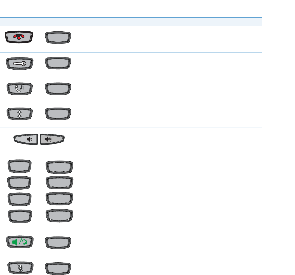
IP Phone Models
1-29 41-001343-02 REV04 – 05.2014
6757i and 6757i CT Symbol and Text Key Descriptions*
Symbol Keys Text Keys Key Description
Goodbye key - Ends an active call. The Goodbye key also exits an open list, such as the Options List, with-
out saving changes.
Options key - Accesses options to customize your phone. Your System Administrator may have already
customized some of your settings. Check with your System Administrator before changing the adminis-
trator-only options.
Hold key - Places an active call on hold. To retrieve a held call, press the call appearance button beside the
light that is flashing.
Redial key - Redials up to 100 previously dialed numbers. Pressing the Redial key twice simultaneously
redials the last dialed number.
Volume control key - Adjusts the volume for the handset, headset, ringer, and handsfree speaker.
Line/Call Appearance key - Connects you to a line or call. The Aastra 6757i IP phone supports up to 4 line
keys.
Handsfree key - Activates Handsfree for making and receiving calls without lifting the handset. When the
audio mode option is set, this key is used to switch between a headset and the handsfree speakerphone.
Mute key - Mutes the microphone so that your caller cannot hear you (the light indicator flashes when the
microphone is on mute).
Goodbye
OptionsOptions
Hold
Redial
L1L1
L2L2
L3L3
L4L4
Line 1
Line 1
Line 2
Line 2
Line 3
Line 3
Line 4
Line 4
Speaker/
Headset
Mute
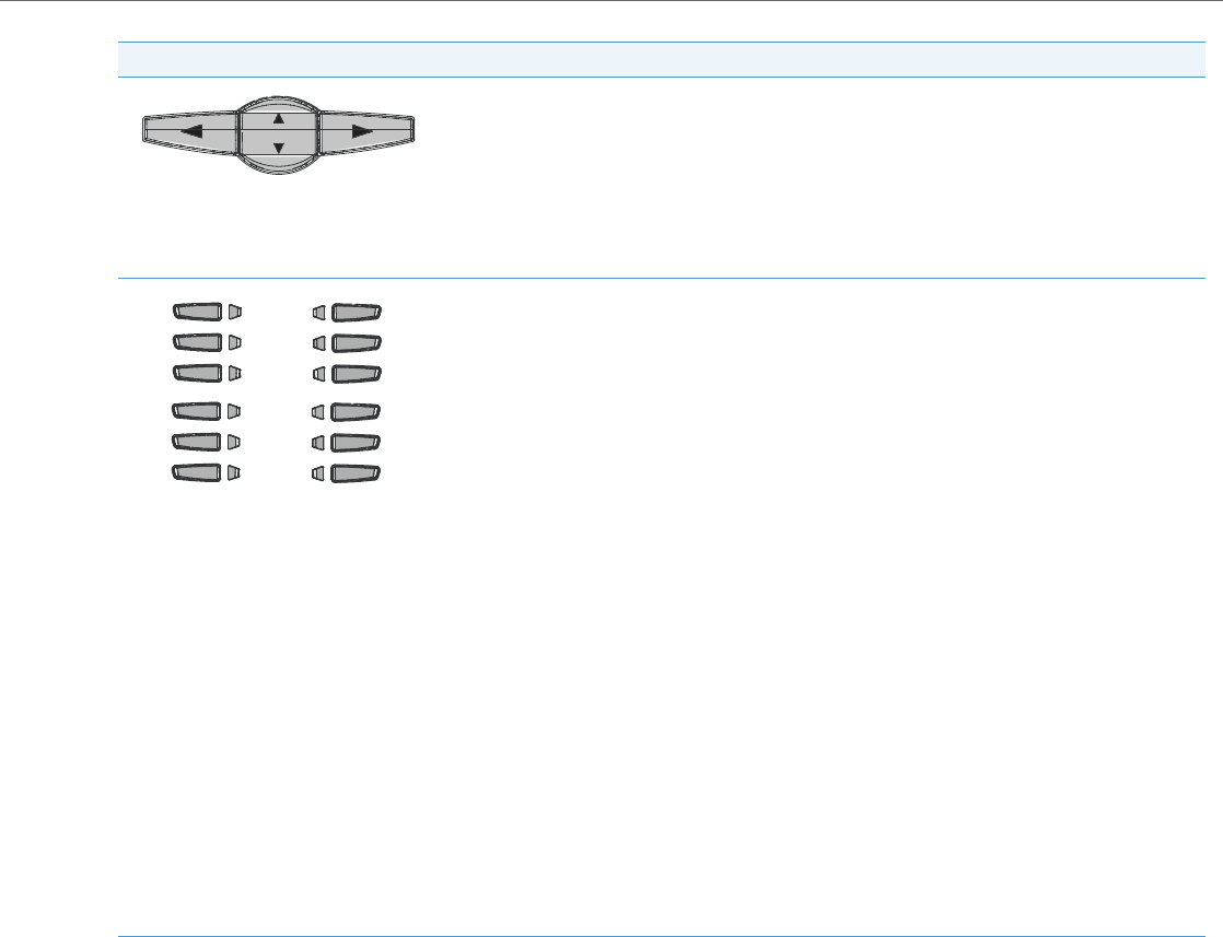
IP Phone Models
41-001343-02 REV04 – 05.2014 1-30
*See the Aastra Model 6757i or 6757i CT IP Phone User Guide for more information about each of these keys.
Navigation keys - Pressing the UP and DOWN arrow keys lets you view different status and text messages
on the LCD display (if there is more than 1 line of status/text messages). These keys also let you scroll
through menu selections, such as the Options List, and scroll through a remote number that is displayed
on the phone. Users can press the scrolling DOWN navigation key to view the rest of the phone number
content.
Pressing the LEFT and RIGHT arrow keys lets you view the different line/call appearances. While in the
Options List, these keys allow you to exit or enter the current option. When you are editing entries on the
display, pressing the LEFT arrow key erases the character on the left; pressing the RIGHT arrow key sets the
option.
Softkeys - 12 softkeys on the 6757i IP Phone.
•6 Top Keys: programmable static softkeys (up to 10 programmable functions)
•6 Bottom Keys: programmable state-based softkeys (up to 20 programmable functions)
By default, the top softkeys 1 through 4 are assigned as Services, Directory, Callers List, and Intercom,
respectively. Keys 5 and 6 have no assigned functions. All 6 keys are programmable and can be assigned
to perform specific functions.
The following are the default functions for the top softkeys on the 6757i IP phone:
1 - SERVICES - Accesses enhanced features and services such as XML applications and voicemail, pro-
vided by third parties.
2 - DIRECTORY - Displays up to 200 names and phone numbers (stored in alphabetical order).
3 - CALLERS LIST - Accesses the last 200 calls received.
4 - ICOM - Accesses another extension on the network.
5 - None
6 - None
7 - None
By default, the bottom softkeys 8 through 12 have no assigned functions. You can configure all 6 bottom
softkeys to perform specific functions on the 6757i IP phone. However, after you lift the handset, there are
specific static softkeys that display that cannot be changed. These are as follows:
7- DIAL - Allows you to dial out on the phone.
8- CONF - Begins a conference call with the active phone.
9- XFERT - ransfers the active call to another number.
Note:
For more information about programming the softkeys to perform specific functions, see Chapter 5, “Con-
figuring Operational Features” the section, “Softkeys/Programmable Keys/Feature Keys/Expansion Mod-
ule Keys” on page5-104.
Symbol Keys Text Keys Key Description

IP Phone Models
1-31 41-001343-02 REV04 – 05.2014
6757i CT Cordless Handset Features
•5-line backlit display screen
•2 multi-functional softkeys
•Programmable function key supports up to 14 functions
•Vibration Alerter
•Headset Jack
•Desk charging stand
1
2
3
4
5
6
7
8
15
9
10
5
11
12
13
15
14
16

IP Phone Models
41-001343-02 REV04 – 05.2014 1-32
6757i CT Cordless Handset Key Descriptions
Function # Function Description
1Receiver
2Volume key
During Ringing: Adjusts ringer volume
During a call: Adjusts receiver volume
During text mode (not in a call): Moves cursor right/left
3Display
4Features ƒ Key List
Access key to the programmed Feature Key List
Scrolls up when in the various lists
Adds a space during editing
5Softkeys
Activates feature or option shown on the display above the keys
6Call key
Used to obtain dial tone
Also used as a Hold key
7Dial Pad
8Mute Key
When used, prevents the caller from hearing you
9Headset Jack
10 Status Light
11 Release key
To end calls and go on hook
Exits Menu and the various lists
12 Menu Key
Access key to the different Options
Scrolls down when in the various lists
Used as Backspace during editing
13 Redial Key
Displays the last 10 numbers dialed
14 Charging Jack
15 Charging Contacts
16 Microphone

IP Phone Models
1-33 41-001343-02 REV04 – 05.2014
Model 6863i IP Phone
This section provides brief information about the Model 6863i IP Phone. It includes a list of features and describes the
hard keys on the 6863i.
6863i Phone Features
•LCD screen
•Built-in-two-port, 10/100 Fast Ethernet switch - lets you share a connection with your computer
•3 programmable keys
•Press-and-hold speeddial key configuration feature
•Supports up to 2 call lines with LEDs
•Wideband handset
•Wideband, full-duplex speakerphone for handsfree calls
•AC power adapter (sold separately)
•Set paging*
*Availability of feature dependant on your phone system or service provider.
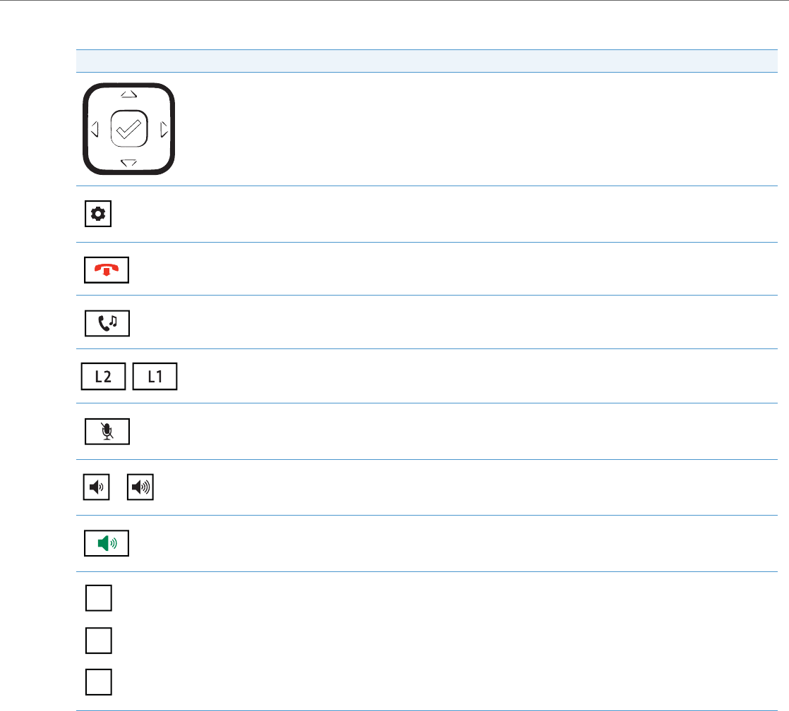
IP Phone Models
41-001343-02 REV04 – 05.2014 1-34
6863i Key Description
Key Description
Navigation/Select Keys - Pressing the UP and DOWN keys lets you view different status and text messages on the LCD display
(if there is more than 1 line of status/text messages). These buttons also let you scroll through menu selections, such as the
Options List.
Pressing the LEFT and RIGHT keys lets you view the different line/call appearances. While in the Options List, these keys allow
you to exit or enter the current option. When you are editing entries on the display, pressing the LEFT key erases the character
on the left; pressing the RIGHT key sets the option. Alternatively, pressing the center Select key sets the option as well on spe-
cific screens.
Options Key - Accesses services and options to customize your phone. Your System Administrator may have already custom-
ized some of your settings. Check with your System Administrator before changing the administrator-only options.
Goodbye Key - Ends an active call. The Goodbye key also exits an open list, such as the Options List, without saving changes.
Hold Key - Places an active call on hold. To retrieve a held call, press the call appearance button beside the light that is flashing.
Line/Call Appearance Keys - Connects you to a line or call. The Aastra 6730i supports two line keys, each with LED indicator
lights.
Mute Key - Mutes the microphone so that your caller cannot hear you (the light indicator flashes when the microphone is on
mute).
Volume Controls - Adjusts the volume for the handset, ringer, and handsfree speaker.
Speaker Key - Transfers the active call to the speaker, allowing handsfree use of the phone.
Programmable Keys - When programmed, allows you to easily perform up to 3 specific functions (e.g. Services, Directory,
Intercom, etc...) and access enhanced services provided by third parties (e.g. XML applications). The programmable keys are
pre-configured as (from top to bottom) Callers, Redial, and Transfer keys.
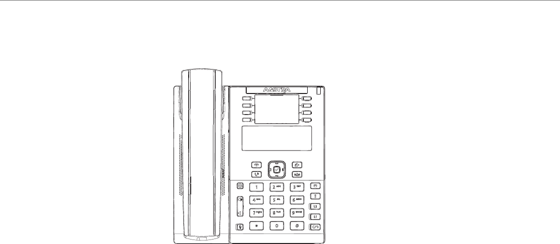
IP Phone Models
1-35 41-001343-02 REV04 – 05.2014
Model 6865i IP Phone
This section provides brief information about the Model 6865i IP Phone. It includes a list of features and describes the
hard keys on the 6865i.
6865i Phone Features
•LCD screen with backlight
•Built-in-two-port, 10/100/1000 Gigabit Ethernet switch - lets you share a connection with your computer
•8 programmable top keys
•Press-and-hold speeddial key configuration feature
•Supports up to 9 call lines with LEDs
•Wideband handset
•Wideband, full-duplex speakerphone for handsfree calls
•Headset mode support
•AC power adapter (sold separately)
•Enhanced busy lamp fields*
•Set paging*
*Availability of feature dependant on your phone system or service provider.
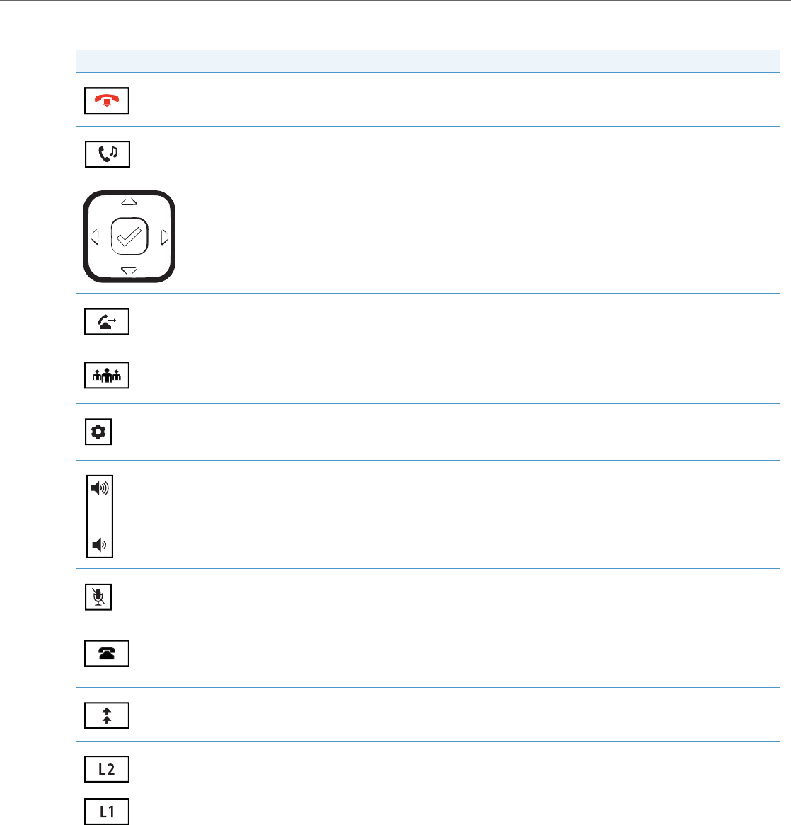
IP Phone Models
41-001343-02 REV04 – 05.2014 1-36
6865i Key Description
Key Description
Goodbye Key - Ends an active call. The Goodbye key also exits an open list, such as the Options List, without saving changes.
Hold Key - Places an active call on hold. To retrieve a held call, press the call appearance button beside the light that is flashing.
Navigation/Select Keys - Pressing the UP and DOWN keys lets you view different status and text messages on the LCD display
(if there is more than 1 line of status/text messages). These buttons also let you scroll through menu selections, such as the
Options List.
Pressing the LEFT and RIGHT keys lets you view the different line/call appearances. While in the Options List, these keys allow
you to exit or enter the current option. When you are editing entries on the display, pressing the LEFT key erases the character
on the left; pressing the RIGHT key sets the option. Alternatively, pressing the center Select key sets the option as well on spe-
cific screens.
Transfer Key - Transfers the active call to another number.
Conference Key - Begins a conference call with the active call.
Options Key - Accesses services and options to customize your phone. Your System Administrator may have already custom-
ized some of your settings. Check with your System Administrator before changing the administrator-only options.
Volume Controls - Adjusts the volume for the handset, ringer, and handsfree speaker.
Mute Key - Mutes the microphone so that your caller cannot hear you (the light indicator flashes when the microphone is on
mute).
Callers List Key - Accesses a list of the last 200 calls received.
Redial Key - Accesses a list of the last 100 previously dialed numbers. Pressing the Redial key twice redials the last dialed
number.
Line/Call Appearance Keys - Connects you to a line or call. The Aastra 6730i IP Phone supports two line keys, each with LED
indicator lights.
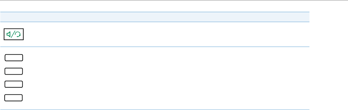
IP Phone Models
1-37 41-001343-02 REV04 – 05.2014
Speaker/Headset Key - Transfers the active call to the speaker or headset, allowing handsfree use of the phone.
Programmable Keys - When programmed, allows you to easily perform up to 8 specific functions (e.g. Services, Directory,
Callers List, Intercom, etc...) and access enhanced services provided by third parties (e.g. XML applications).
Key Description

IP Phone Models
41-001343-02 REV04 – 05.2014 1-38
Model 6867i IP Phone
This section provides brief information about the Model 6867i IP Phone. It includes a list of features and describes the hard
keys on the 6867i.
6867i Phone Features
•3.5” QVGA color TFT LCD with backlight
•Built-in-two-port, 10/100/1000 Gigabit Ethernet switch - lets you share a connection with your computer
•USB 2.0 port (100mA maximum)
•6 programmable and 4 context-sensitive softkeys
•Press-and-hold speeddial key configuration feature
•Supports up to 9 call lines with LEDs
•Wideband handset
•Wideband, full-duplex speakerphone for handsfree calls
•Headset mode support
•AC power adapter (sold separately)
•Enhanced busy lamp fields*
•Set paging*
*Availability of feature dependant on your phone system or service provider.
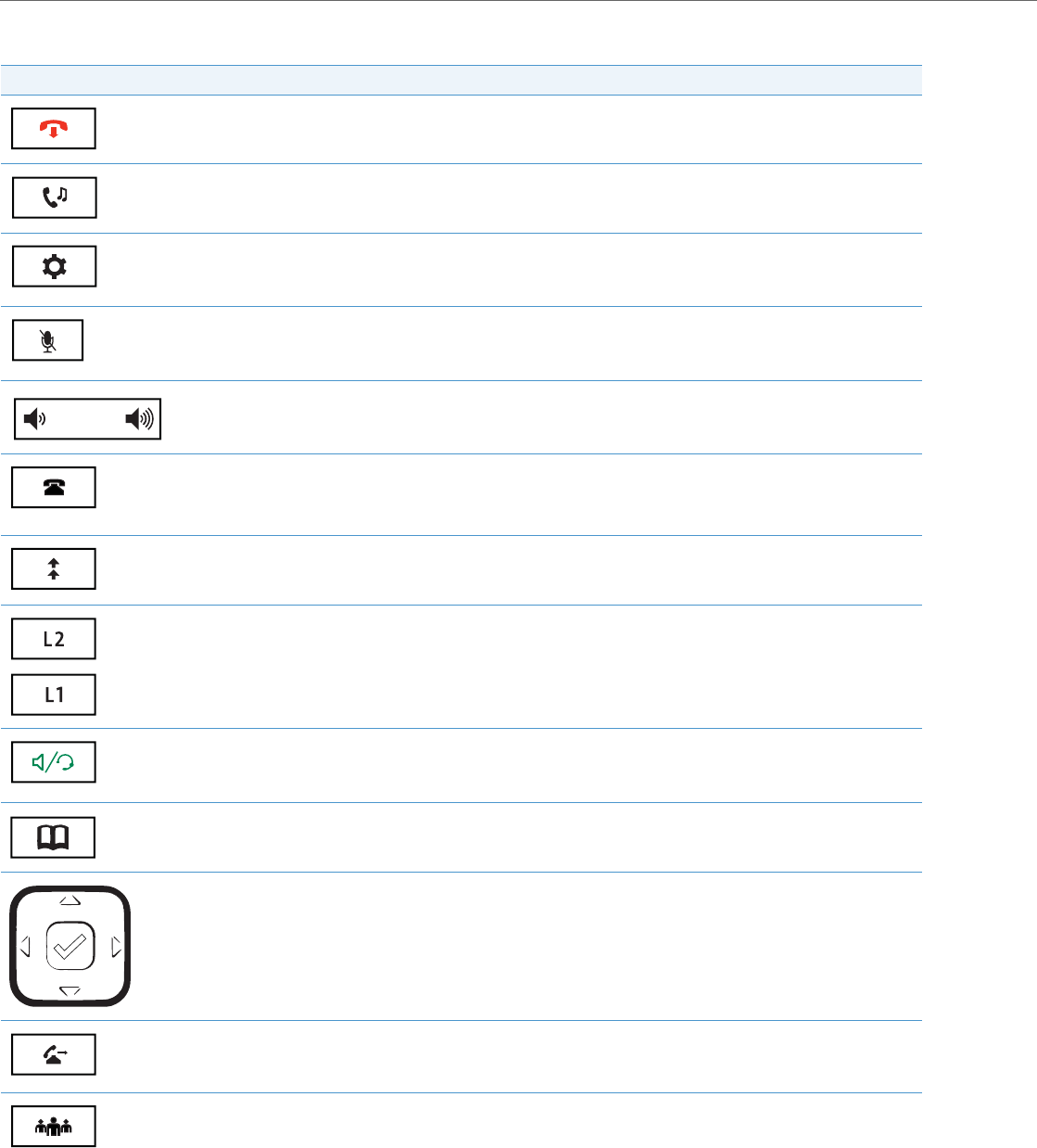
IP Phone Models
1-39 41-001343-02 REV04 – 05.2014
6867i Key Description
Key Description
Goodbye Key - Ends an active call. The Goodbye key also exits an open list, such as the Options List, without saving
changes.
Hold Key - Places an active call on hold. To retrieve a held call, press the call appearance button beside the light that is
flashing.
Options Key - Accesses services and options to customize your phone. Your System Administrator may have already cus-
tomized some of your settings. Check with your System Administrator before changing the administrator-only options.
Mute Key - Mutes the microphone so that your caller cannot hear you (the light indicator flashes when the microphone
is on mute).
Volume Controls - Adjusts the volume for the handset, ringer, and handsfree speaker.
Callers List Key - Accesses a list of the last 200 calls received.
Redial Key - Accesses a list of the last 100 previously dialed numbers. Pressing the Redial key twice redials the last dialed
number.
Line/Call Appearance Keys - Connects you to a line or call. The Aastra 6730i IP Phone supports two line keys, each with
LED indicator lights.
Speaker/Headset Key - Transfers the active call to the speaker or headset, allowing handsfree use of the phone.
Directory Key - Accesses a directory of names and phone numbers (stored in alphabetical order).
Navigation/Select Keys - Multi-directional navigation keys allow you to navigate through the phone’s user interface.
Pressing the center Select key selects/sets options and performs various actions (such as dialing out when in the Direc-
tory, Callers, and Redial Lists).
Transfer Key - Transfers the active call to another number.
Conference Key - Begins a conference call with the active call.
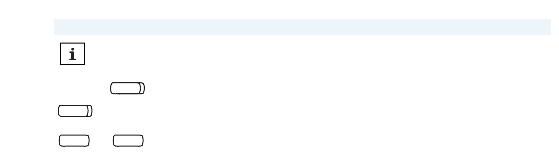
IP Phone Models
41-001343-02 REV04 – 05.2014 1-40
Presence Key - Accesses the partial and full contact presence information screens, which provide more detailed infor-
mation about the selected contact.
Left Softkeys - 6 programable keys that allow you to easily perform up to 20 specific functions and access enhanced
services provided by third parties (e.g. XML applications).
Bottom Softkeys - 4 programmable keys that support up to 18 functions. These keys also act as state-based keys allow-
ing you to easily perform context-senstive functions during specific states (i.e. when the phone is an idle, connected,
incoming, outgoing, or busy state).
Key Description

IP Phone Models
1-41 41-001343-02 REV04 – 05.2014
Model 9143i IP Phone
This section provides brief information about the Model 9143i IP Phone. It includes a list of features and describes the
hard keys on the 9143i.
9143i Phone Features
•3-line LCD screen
•3 call appearance lines with LEDs
•7 programmable keys
•Press-and-Hold speed dial key configuration feature
•Full-duplex speakerphone for handsfree calls
•Supports up to 9 call lines
•Headset support (modular connector)
•Built-in two-port, 10/100 Ethernet ports - lets you share a connection with your computer
•Inline power support (based on 802.3af standard) which eliminates power adapters.
•AC power adapter (included)
•Enhanced busy lamp fields*
•Set paging*
*Availability of feature dependant on your phone system or service provider.
Xfer
Conf
L2
L3
L1
Options
Save
Delete
Directory
Mute
ABC DEF
GHI JKL MNO
PQRS
TUV
WXYZ
1
4
3
6
2
5
798
0
*#
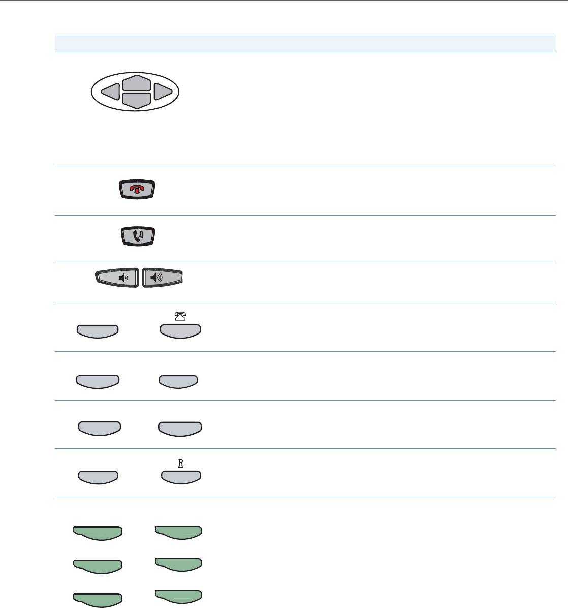
IP Phone Models
41-001343-02 REV04 – 05.2014 1-42
9143i Symbol and Text Key Descriptions*
Text Keys Symbol Keys Key Description
Navigation Keys - Pressing the UP and DOWN arrow keys lets you view different status and text
messages on the LCD display (if there is more than 1 line of status/text messages). These keys also
let you scroll through menu selections, such as the Options List, and scroll through a remote
number that is displayed on the phone. Users can press the scrolling DOWN navigation key to view
the rest of the phone number content.
Pressing the LEFT and RIGHT arrow keys lets you view the different line/call appearances. While in
the Options List, these keys allow you to exit or enter the current option.
When you are editing entries on the display, pressing the LEFT arrow key works as a backspace
instead of a moving cursor. the LEFT arrow key erases the digit/character at the cursor location
including the dot/decimal. The RIGHT arrow key sets the option.
Goodbye Key - Ends an active call. The Goodbye key also exits an open list, such as the Options List,
without saving changes.
Hold Key - Places an active call on hold. To retrieve a held call, press the call appearance key beside
the light that is flashing.
Volume Control Key - Adjusts the volume for the handset, headset, ringer, and handsfree speaker.
Callers List Key - Allows you to access the Callers List that stores up to 200 of the last calls received.
Conference Key - Allows you to begin a conference call(s) with the active call.
Transfer Key - Allows you to perform blind or consultative transfer of an active call to another
number. In blind transfer, you transfer the call without waiting for the far end to answer. In consult-
ative transfer, you wait for the far end to answer before transferring the call.
Redial Key - Redials a previously dialed number. The Redial key stores up to 100 previously dialed
numbers you can select from. Pressing the Redial key twice simultaneously redials the last dialed
number.
Line/Call Appearance Key - Connects you to a line or call. The Aastra 9143i IP Phone supports up
to 3 line keys.
Callers
Conference
Conf
Transfer
Xfer
Redial
Line 2
Line 3
Line 1
L2
L3
L1
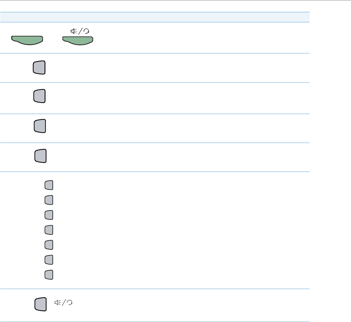
IP Phone Models
1-43 41-001343-02 REV04 – 05.2014
*See the Aastra Model 9143i IP Phone User Guide for more information about each of these keys.
Handsfree Key - Activates Handsfree for making and receiving calls without lifting the handset.
When the audio mode option is set, this key is used to switch between a headset and the handsfree
speakerphone.
Options Key - Accesses options to customize your phone. Specific options are available to your
System Administrator only and are password protected. Contact your System Administrator for
more information about Administrator options.
Directory Key - Accesses the Directory on the phone. The Directory List is your personal phone
book, conveniently stored within your phone. You can enter up to 200 entries into the 9143i Direc-
tory by adding them manually, or by saving the number and name from other lists stored on your
phone. Each entry can contain a maximum of 16 letters and
numbers.
Save Key - Allows you to save entries when storing numbers and names in Directory. Also allows
you to save Option settings when using the programmable keys.
Delete Key - Allows you to remove entries from the Redial, Directory, or Callers Lists.
Programmable Keys - Allows you to use the feature configured for that key. You can program up
to 7 keys with a specific function.
Mute Key - Mutes the microphone so that your caller cannot hear you (the light indicator flashes
when the microphone is on mute).
Text Keys Symbol Keys Key Description
Speaker / Headset
Options
Directory
Save
Delete
Mute

IP Phone Models
41-001343-02 REV04 – 05.2014 1-44
Model 9480i and 9480i CT IP Phones
This section provides brief information about the Models 9480i and 9480i CT IP Phones. It includes a list of features and
describes the hard keys on these models.
9480i and 9480i CT Phone Features
•5-line graphical LCD screen with large backlit display
•6 multi-functional, state-based softkeys
•Press-and-Hold speed dial key configuration feature
•4 call appearance lines with LEDs
•Supports up to 9 call lines
•Speakerphone for handsfree calls
•Headset support (modular connector)
•Built-in-two-port, 10/100 Ethernet switch - lets you share a connection with your computer.
•Inline power support (based on 802.3af standard) which eliminates power adapters.
•AC power adapter (included)
•Enhanced busy lamp fields*
•Set paging*
*Availability of feature dependant on your phone system or service provider.
35i
35i
C
onf
onf Ser
vi
vic
es
es
Xf
er
er Ic
om
om
ABC
ABC
DEF
DEF
GHI
GHI
JKL
JKL
MNO
MNO
PQRS
PQ RS
TUV
TU V
WX
YZ
YZ
1
4
3
6
2
5
7 98
0
*
#
G
ood
oodbye
Options
Options
Hold
Hold R
edial
edial
L1
L1
L2
L2
L3
L3
L4
L4
35i
35i
C
onf
onf Ser
vi
vic
es
es
Xf
er
er Ic
om
om
ABC
ABC
DEF
DEF
GHI
GHI
JKL
JKL
MNO
MNO
PQRS
PQ RS
TUV
TU V
WX
YZ
YZ
1
4
3
6
2
5
7 98
0
*
#
G
ood
oodbye
Options
Options
Hold
Hold R
edial
edial
L1
L1
L2
L2
L3
L3
L4
L4
9480i 9480i CT
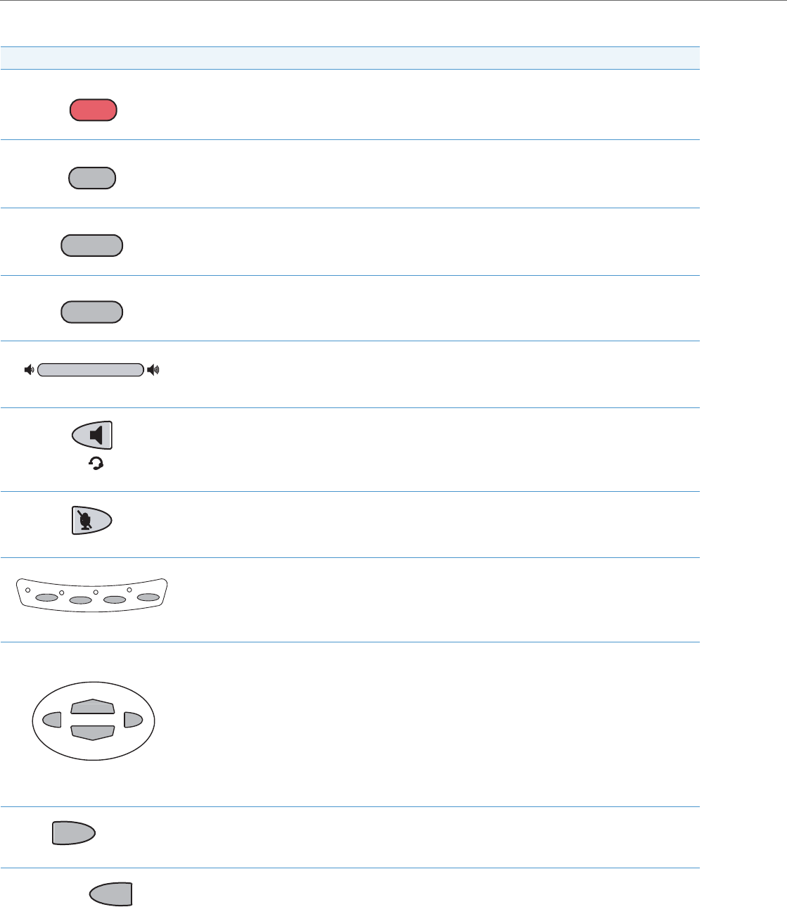
IP Phone Models
1-45 41-001343-02 REV04 – 05.2014
9480i and 9480i CT Key Descriptions*
Keys Key Description
Goodbye key - Ends an active call. The Goodbye key also exits an open list, such as the Options List, without
saving changes.
Options key - Accesses options to customize your phone. Your System Administrator may have already cus-
tomized some of your settings. Check with your System Administrator before changing the administrator-only
options.
Hold key - Places an active call on hold. To retrieve a held call, press the call appearance button beside the light
that is flashing.
Redial key - Redials up to 100 previously dialed numbers. Pressing the Redial key twice simultaneously redials
the last dialed number.
Volume control key - Adjusts the volume for the handset, headset, ringer, and handsfree speaker.
Handsfree key - Activates Handsfree for making and receiving calls without lifting the handset. When the
audio mode option is set, this key is used to switch between a headset and the handsfree speakerphone.
Mute key - Mutes the microphone so that your caller cannot hear you (the light indicator flashes when the
microphone is on mute).
Line/Call Appearance key - Connects you to a line or call. The Aastra 9480i and 9480i CT IP phones support up
to 4 line keys.
Navigation keys - Pressing the UP and DOWN arrow keys lets you view different status and text messages on
the LCD display (if there is more than 1 line of status/text messages). These keys also let you scroll through
menu selections, such as the Options List, and scroll through a remote number that is displayed on the phone.
Users can press the scrolling DOWN navigation key to view the rest of the phone number content.
Pressing the LEFT and RIGHT arrow keys lets you view the different line/call appearances. While in the Options
List, these keys allow you to exit or enter the current option. When you are editing entries on the display, press-
ing the LEFT arrow key erases the character on the left; pressing the RIGHT arrow key sets the option.
Transfer key - Transfers an active call to another number.
Conference key - Begins a conference call with the active call.
Goodoodbye
Options
Options
Hold
Hold
R
R
edial
edial
L1L1 L2L2 L3L3 L4L4
Xf
er
er
Conf
Conf
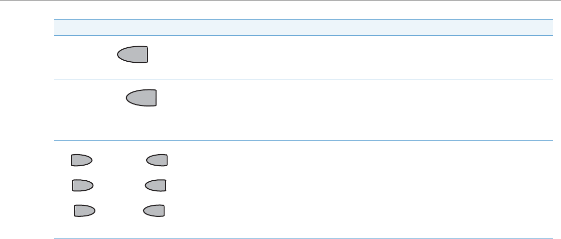
IP Phone Models
41-001343-02 REV04 – 05.2014 1-46
*See the Aastra 9480i and 9480i CT User Guides for more information about each of these keys.
Icom key - Begins an intercom call to a remote extension and answers incoming intercom calls. The 9480i and
9480i CT IP Phones also have default softkey 4 configured as Icom.
Services key - Displays a list of Services available to your phone, if specific services have been configured. The
available Aastra services include Directory & Callers Log. The 9480i and 9480i CT IP Phones also have default
softkey 1 configured as Services.
Note:
Availability of the services feature is dependant on your phone system and/or service provider.
Softkeys - 6 state-based softkeys on the 9480i and 9480i CT IP Phones.
When you pick up the handset, the following displays on key 1:
Dial - After entering a phone number from the keypad, you can press the Dial softkey to immediately dial the
number.
Note:
For more information about configuring softkeys 1 through 6 to perform specific functions, see Chapter 5,
“Configuring Operational Features” the section, “Softkeys/Programmable Keys/Feature Keys/Expansion Mod-
ule Keys” on page5-104.
Keys Key Description
Icomom
SSeerrvi
vi
cces
es

IP Phone Models
1-47 41-001343-02 REV04 – 05.2014
9480i CT Cordless Handset Features
•5-line backlit display screen
•2 multi-functional softkeys
•Programmable function key supports up to 14 functions
•Vibration Alerter
•Headset Jack
•Desk charging stand
1
2
3
4
5
6
7
8
15
9
10
5
11
12
13
15
14
16

IP Phone Models
41-001343-02 REV04 – 05.2014 1-48
9480i CT Cordless Handset Key Descriptions*
*See the Aastra Model 9480i CT IP Phone User Guide for more information about each of these keys.
Function # Function Description
1Receiver
2Volume key
During Ringing: Adjusts ringer volume
During a call: Adjusts receiver volume
During text mode (not in a call): Moves cursor right/left
3Display
4Features ƒ Key List
Access key to the programmed Feature Key List
Scrolls up when in the various lists
Adds a space during editing
5Softkeys
Activates feature or option shown on the display above the keys
6Call key
Used to obtain dial tone
Also used as a Hold key
7Dial Pad
8Mute Key
When used, prevents the caller from hearing you
9Headset Jack
10 Status Light
11 Release key
To end calls and go on hook
Exits Menu and the various lists
12 Menu Key
Access key to the different Options
Scrolls down when in the various lists
Used as Backspace during editing
13 Redial Key
Displays the last 10 numbers dialed
14 Charging Jack
15 Charging Contacts
16 Microphone

Firmware Installation Information
1-49 41-001343-02 REV04 – 05.2014
Firmware Installation Information
Description
The firmware setup and installation for the IP phone can be done using any of the following:
•Phone User Interface via the keypad (Phone UI)
•Aastra Web-based user interface (Aastra Web UI)
When the IP phone is initialized for the first time, DHCP is enabled by default. Depending on the type of configuration
server setup you may have, the IP phone may download a firmware version automatically, or you may need to download
it manually.
Installation Considerations
The following considerations must be made before connecting the IP phone to the network:
•If you are planning on using dynamic IP addresses, make sure a DHCP server is enabled and running on your network.
•If you are not planning on using dynamic IP addresses, see Chapter 4, the section, “Configuring Network Settings
Manually” on page4-18 for manually setting up an IP address.
To install the IP phone hardware and cabling, refer to the <Model-Specific> SIP IP Phone Installation Guide.
Installation Requirements
The following are general requirements for setting up and using your SIP IP phone:
•SIP-based IP PBX system or network installed and running with a SIP account created for the IP phone
•Access to a Trivial File Transfer Protocol (TFTP), File Transfer Protocol (FTP), Hypertext Transfer Protocol (HTTP) server,
or Hyper Text Transfer Protocol over Secure Sockets Layer (SSL) (HTTPS)
•Ethernet/Fast Ethernet LAN (10/100 Mb) (Gigabit Ethernet LAN [1000 Mbps] recommended for Gigabit Ethernet com-
pliant phones)
•Category 5/5e straight through cabling (Category 6 straight-through cabling recommended for Gigabit Ethernet com-
pliant phones)
•Power source
–For Ethernet networks that supply inline power to the phone (IEEE 802.3af) use an Ethernet cable to connect from
the phone directly to the network for power (no 48V AC power adapter required if using Power-over-Ethernet
[PoE])
–For Ethernet networks that DO NOT supply power to the phone:
Use the respective power adaptor to connect from the DC power port on the phone to a power source
or
Use a PoE power injector or a PoE switch
Configuration Server Requirement
A basic requirement for setting up the IP phone is to have a configuration server. The configuration server allows you to:
•Store the firmware images that you need to download to your IP phone
•Stores configuration files for the IP phone
Reference
To set the protocol for your configuration server, see Chapter 4, “Configuring Network and Session Initiation Protocol
(SIP) Features”, the section, “Configuring the Configuration Server Protocol” on page4-87.
To update the firmware on your phone, see Chapter 8, “Upgrading the Firmware”.

Firmware and Configuration Files
41-001343-02 REV04 – 05.2014 1-50
Firmware and Configuration Files
Description
By default on startup, the phone downloads its firmware and configuration files from the configuration server you have
set; or you can manually download the firmware from the configuration server. The phone supports TFTP, FTP, HTTP and
HTTPS configuration servers.
The IP Phone firmware file (.st) include all the necessary files you need for your phone.
The firmware consists of the following file:
•<phone model>.st - This file contains information about the specific IP Phone model and contains the language packs
to load to the phone.
The configuration files consist of three files called:
•aastra.cfg - This file contains configuration information about the IP Phone.
•<model>.cfg (for example, 6757i.cfg) - This file contains model specific information, where “model” should be the same
string that is used for the model name (e.g. 6730i.cfg, 6731i.cfg, 6735i.cfg, 6737i.cfg, 6739i.cfg, 6753i.cfg, 6755i.cfg,
6757i.cfg, 6757iCT.cfg, 6863i.cfg, 6865i.cfg, 6867i.cfg, 9143i.cfg, 9480i.cfg, 9480iCT.cfg).
•<MAC>.cfg (for example, 00085D1610DE.cfg) - This file contains configuration information about the IP Phone.
The following table provides the files that the phone requests from the configuration server during bootup of the phone:
Note:
Automatic download is dependant on your configuration server setup. For more information about manual and auto-
matic download of firmware, see Chapter 8, “Upgrading the Firmware.” For more information on changing the down-
load protocol on your phone, see Chapter 4, the section, “Configuring the Configuration Server Protocol” on page4-87.
IP Phone Model Associated Firmware Configuration Files Language Files
9143i 9143i.st aastra.cfg
<model>.cfg
(for example,
6757i.cfg)
<MAC>.cfg
(for example, 00085D1610DE.cfg)
lang_cs.txt (Czech - UTF-8)
lang_cs_op.txt (Czech - ASCII)
lang_ct.txt (Catalan)
lang_ct_va.txt (Valencian)
lang_cy.txt (Welsh)
lang_de.txt (German)
lang_da.txt (Danish)
lang_es.txt (Spanish)
lang_es_mx.txt (Mexican Spanish)
lang_fi.txt (Finnish)
lang_fr.txt (French)
lang_fr_ca.txt (Canadian French)
lang_it.txt (Italian)
lang_nl.txt (Dutch)
lang_nl_nl.txt (Dutch - Netherlands)
lang_no.txt (Norwegian)
lang_pl.txt (Polish - ASCII)
lang_pl_pl.txt (Polish - UTF-8)
lang_pt.txt (Portuguese)
lang_pt_br.txt (Brazillian Portuguese)
lang_ro.txt (Romanian)
lang_ru.txt (Russian)
lang_sk.txt (Slovak - UTF-8)
lang_sk_op.txt (Slovak - ASCII)
lang_sv.txt(Swedish)
lang_tr.txt (Turkish)
9480i 9480i.st
9480i CT 9480iCT.st
6730i 6730i.st
6731i 6731i.st
6735i 6735i.st
6737i 6737i.st
6739i 6739i.st
6753i 53i.st
6755i 55i.st
6757i 57i.st
6757i CT 57iCT.st
6863i 6863i.st
6865i 6865i.st
6867i 6867i.st

Firmware and Configuration Files
1-51 41-001343-02 REV04 – 05.2014
Reference
For more information about loading language files and using the various languages on the IP phone, see Chapter 5, the
section, “Language” on page5-38.
Configuration File Precedence
Aastra IP phones can accept three sources of configuration data:
•The server configuration most recently downloaded/cached from the configuration server files, aas-
tra.cfg/<model>.cfg/<mac>.cfg (or the aastra.tuz/<model>.tuz/<mac>.tuz encrypted equivalents)
•Local configuration changes stored on the phone that were entered using either the IP phone UI or the Aastra Web UI
If the same parameter appears more than once in the above configuration files, the last parameter/value read will be
used (i.e., the following precedence rules will apply):
•Settings in the <model>.cfg file can overwrite aastra.cfg settings
•Settings in the <mac>.cfg file can overwrite <model>.cfg settings
In the event of conflicting values set by the different methods, values are applied in the following sequence:
The last values to be applied to the phone configuration are the values that take effect.
For example, if a parameter’s value is set in the local configuration (via Aastra Web UI or IP phone UI) and the same value
was also set differently in one of the aastra.cfg/<model>.cfg/<mac>.cfg files on the configuration server, the local config-
uration value is the value that takes effect because that is the last value applied to the configuration.
Installing the Firmware/Configuration Files
The following procedure describes how to install the firmware and configuration files.
1. Default values hard-coded in the phone software
2. Values downloaded from the configuration server
3. Values stored locally on the phone
1. If DHCP is disabled, manually enter the configuration server’s IP address. For details on manually setting DHCP, see Chapter 4, the section
“DHCP” on page4-3.
2. Copy the firmware file <phone model>.st to the root directory of the configuration server. The IP phone accepts the new firmware file only
if it is different from the firmware currently loaded on the IP phone.
Note:
The <phone model> attribute is the IP phone model (i.e., 9143i.st, 9480i.st, 9480iCT.st, 6730i.st, 6731i.st, 6735i.st, 6737i.st, 6739i.st, 51i.st,
53i.st, 55i.st, 57i.st, 57iCT.st).
3. Copy the Aastra configuration files (aastra.cfg, <model>.cfg, and <mac>.cfg) to the root directory of the configuration server.
Note:
The <mac> attribute represents the actual MAC address of your phone (i.e. 00085D030996.cfg).
The <model> represents a specific model of phone. (i.e.,6757i.cfg).
4. Note:
Restart the IP phone as described in Chapter 3, “Restarting Your Phone” on page3-11.

Firmware and Configuration Files
41-001343-02 REV04 – 05.2014 1-52
Multiple Configuration Server Support
An Administrator has the option of specifying whether the phones get their firmware file, directory files, language packs,
TLS certificate files, 802.1x certificate files, and HTTPS files from the original configuration server or from another server in
the network. This feature allows you to specify the URL of other servers from which the phone can get this information.
Firmware Files and Multiple Configuration Servers
The firmware file for the phones can be downloaded from the original configuration server or from another server speci-
fied by a URL. You can specify a valid full or partial URL (server IP address) from which the phones get the firmware using a
new parameter called, “firmware server” in the configuration files. If a full URL is specified for this parameter, the phones
in the network get the security.tuz, aastra.cfg, <model>.cfg, and <mac>.cfg files from the original configuration server, and
the firmware files from the server specified in the URL.
When the “firmware server” parameter specifies a partial URL path, the configuration server that is linked to the partial
path is used to load the firmware.
For example,
firmware server: /path
When there is no “firmware server” parameter (or if it is empty), the original configuration server is used to load the
firmware.
Examples
To download all configuration and firmware files from the original configuration server:
firmware server:
Leaving this parameter blank downloads all configuration and firmware files from the original configuration server.
To download all firmware files from another specified server:
firmware server: tftp://10.30.102.158/test1
The above example uses TFTP to download all firmware files that exist in the “test1” directory on the specified server, to
the phone.
To download a partial from another specified server:
firmware server: /path
The above example uses the configuration server that is linked to the partial path to load the firmware.
Note:
The default method for the download of all files and firmware to the phones is from the original configuration server.
The Administrator must specify a correct full or partial server URL for the phones to get their firmware information
from that server. If the URL is incorrect, no firmware download occurs to the phones from the specified server.
Note:
Specifying the download of a “.st” file is not supported. For example, the following filename should NEVER be entered
as a value string for the “firmware server” parameter:
firmware server: tftp://10.30.102.158/test1/57i.st

Firmware and Configuration Files
1-53 41-001343-02 REV04 – 05.2014
Specifying a Server to Download Firmware Files
You can use the following parameter to specify a server other than the original configuration server from which the
phones get their firmware:
•firmware server
Directory Files, Language Packs, TLS Certificates, 802.1x Certificates, HTTPS Files and Multiple
Configuration Servers
The directory files, language packs, TLS certificate files, 802.1x certificate files, and HTTPS files can also be downloaded to
the phone from a server other than the configuration server. For each of these types of files, you can specify a URL (server
IP address) from which the phone gets these files. You can use existing parameters on the phone to specify the URL. For
applicable parameters, see “Specifying a Server Using Existing Parameters on the IP Phones” on page1-54.
The following table specifies the files that the original configuration server downloads, and the files that another server
can download to the phone.
Configuration Files
For the specific parameter(s) you can set in the configuration files, see Appendix A, the section, “Multiple Configuration
Server Settings” on page A-24.
Files always downloaded from original configuration server
are, by order: All files that can be downloaded from original configuration server
OR another specified server are, by order:
security.tuz
aastra.cfg/aastra.tuz
<model>.cfg/<model>.tuz
<mac>.cfg/<mac>.tuz
Directory Files
•directory 1
•directory 2
Language Pack Files
•language 1
•language 2
•language 3
•language 4
Transport Layer Security (TLS) Certificate Files
•sips root and intermediate certificates
•sips local certificate
•sips private key
•sips trusted certificates
802.1x Security Authentication Certificate Files
•802.1x root and intermediate certificates:
•802.1x local certificate:
•802.1x trusted certificates
HTTPS Files
•https user certificates

Firmware and Configuration Files
41-001343-02 REV04 – 05.2014 1-54
Specifying a Server Using Existing Parameters on the IP Phones
The following table provides the parameters on the phone that you can use to download directory files, language packs,
TLS certificates, 802.1x certificates, and HTTPS files from the original configuration server OR from another server in the
network.
Reference
For more information on each of these parameters, refer to AppendixA, “Configuration Parameters.”
Examples
Phone Directory Files
The following example downloads no directory:
directory 1:
The following example downloads a company directory from the original configuration server:
directory 1:companylist.csv
Type of File Parameters that support the Multiple Configuration Server feature are:
Directory Files directory 1:
directory 2:
Language Pack Files language 1:
language 2:
language 3:
language 4:
Valid files names you can specify for languages are:
lang_cs.txt (Czech - UTF8)
lang_cs_op.txt (Czech - ASCII)
lang_ct.txt (Catalan)
lang_ct_va.txt (Valencian)
lang_cy.txt (Welsh)
lang_de.txt (German)
lang_da.txt (Danish)
lang_es.txt (Spanish)
lang_es_mx.txt (Mexican Spanish)
lang_fi.txt (Finnish)
lang_fr.txt (French)
lang_fr_ca.txt (Canadian French)
lang_it.txt (Italian)
lang_nl.txt (Dutch)
lang_nl_nl.txt (Dutch - Netherlands)
lang_no.txt (Norwegian)
lang_pl.txt (Polish - ASCII)
lang_pl_pl.txt (Polish - UTF8)
lang_pt.txt (Portuguese)
lang_pt_br.txt (Brazillian Portuguese)
lang_ro.txt (Romanian)
lang_ru.txt (Russian)
lang_sk.txt (Slovak - UTF8)
lang_sk_op.txt (Slovak - ASCII)
lang_sv.txt(Swedish)
lang_tr.txt (Turkish)
Transport Layer Security (TLS) Certificate Files sips root and intermediate certificates:
sips local certificate:
sips private key:
sips trusted certificates:
802.1x Security Authentication Certificate Files 802.1x root and intermediate certificates:
802.1x local certificate:
802.1x trusted certificates:
HTTPS Files https user certificates

Firmware and Configuration Files
1-55 41-001343-02 REV04 – 05.2014
The following example downloads a company directory file from the specified server in the “path” directory:
directory 1: tftp://10.30.102.158/path/companylist.csv
Language Pack Files
The following example downloads no language pack file:
language 1:
The following example downloads the German language pack to the phones from the original configuration server:
language 1: lang_de.txt
The following example uses FTP to download the firmware file “lang_de.txt” (German language pack) from the “path”
directory on server 1.2.3.4 using port 50:
language 1:ftp://admin:admin!@1.2.3.4:50/path/lang_de.txt
Transport Layer Security (TLS) Certificate Files
The following example downloads no local certificate file:
sips local certificate:
The following example downloads the local certificate file from the original configuration server.
sips local certificate: phonesLocalCert.pem
The following example uses FTP to download the firmware file “phonesLocalCert.pem” (local certificate file) from the
“path” directory on server 1.2.3.4 using port 50.
sips local certificate:ftp://admin:admin!@1.2.3.4:50/path/phonesLocalCert.pem
802.1x Security Authentication Certificate Files
The following example downloads no 802.1x local certificate file:
802.1x local certificate:
The following example downloads the 802.1x local certificate for the phone from the original configuration server.
802.1x local certificate: 8021xlocalCert.pem
The following example uses FTP to download the firmware file “8021xlocalCert.pem” (802.1x local certificate file) from
the “path” directory on server 1.2.3.4 using port 50.
802.1x local certificate:ftp://admin:admin!@1.2.3.4:50/path/8021xlocalCert.pem
HTTPS User Certificate Files
The following example downloads no HTTPS user certificate files:
https user certificates:
The following example downloads the HTTPS user certificates for the phone from the original configuration server.
https user certificates: trustedCerts.pem
The following example uses FTP to download the firmware file “user.crt.pem” (https user certificate file) from the “test1”
directory on server 12.43.33.234 using port 50.
https user certificates: ftp://test:password@12.43.33.234:50/test1/user.crt.pem
Note:
To download a specific file, the string value MUST HAVE A FILENAME at the end of the string. For example:
directory 1: tftp://10.30.102.158/path/companylist.csv
where “path” is the directory and “companylist.csv” is the filename. If you do not specify a filename, the download
fails.

41-001343-02 REV04 – 05.2014 2-1
Chapter 2
Configuration Interface Methods
About this Chapter
This chapter describes the methods you, as an Administrator, can use to configure the IP phones.
Topics
This chapter covers the following topics:
Note:
Features, characteristics, requirements, and configuration that are specific to a particular phone model are indicated
where required in this guide.
Topic Page
Configuration Methods page2-2
IP Phone UI page2-2
Aastra Web UI page2-6
Configuration Files (Administrator Only) page2-14

Configuration Methods
2-2 41-001343-02 REV04 – 05.2014
Configuration Methods
Description
You can use the following to setup and configure the IP phone:
•IP phone UI
•Aastra Web UI
•Configuration files
The following paragraphs describe each method of configuring the IP Phone.
IP Phone UI
The IP Phone User Interface (UI) provides an easy way to access features and functions for using and configuring the IP
phone. Access to specific features and functions are restricted to the Administrator. A User can configure a subset of
these features and functions. Users of the IP phones should see their <Model-Specific> IP Phone User Guide for available
features and functions.
Reference
Refer to Chapter 1, the section “IP Phone Models” on page1-2 for keys specific to your phone model.
For more information about using the hard keys on each phone, see Chapter 5, the section, “Locking IP Phone Keys” on
page5-49.
For more information about the softkeys/programmable keys, see Chapter 5, the section, “Softkeys/Programmable
Keys/Feature Keys/Expansion Module Keys” on page5-104.
Options Key
The Options key allows you to access the "Options List" on the IP phone. Accessible options in this list are for both User
and Administrator use. The Administrator must enter a password for administrator options.
This document describes the administrator options only. For a description of the user options in the "Options List", see
your <Model-Specific> IP Phone User Guide.
Note:
Not all parameters are available from all three methods. For more information about configuring the phone, see Chap-
ter 4, Chapter 5, and Chapter 6.
Note:
An Administrator can apply a simplified options menu to the IP phones. An Administrator can also enable and disable
the use of an Administrator password protection in the IP phone UI. These features are configurable using the config-
uration files only. For more information about these features, see Chapter 3, the section, “Simplified IP Phone UI
Options Menu” on page page3-4, and Chapter 5, the section, “Administrator Passwords” on page5-7.
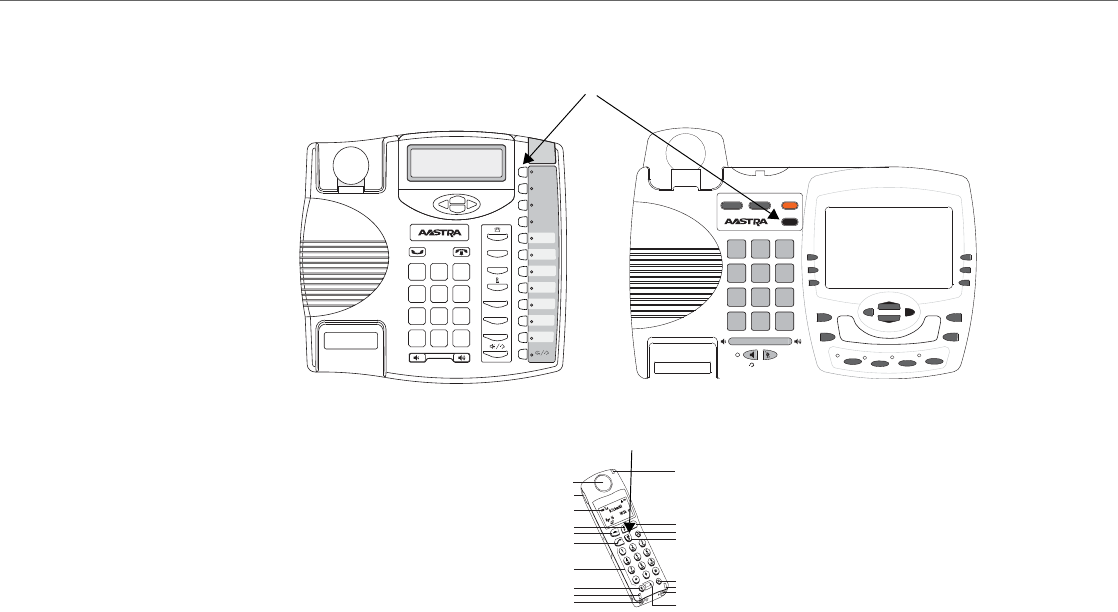
Configuration Methods
41-001343-02 REV04 – 05.2014 2-3
The following illustrations indicate the location of the Options Key on each phone model.
9480i/9480i CT
9480i CT Handset
1
2
3
4
5
6
7
8
15
9
10
5
11
12
13
15
14
16
Options Key
Options Key
9143i
Xfer
Conf
L2
L3
L1
Options
Save
Delete
Directory
Mute
ABC DEF
GHI JKL MNO
PQRS
TUV
WXYZ
1
4
3
6
2
5
798
0
*#
9480i
Conf Services
Xfer Icom
ABC DEF
GHI JKL MNO
PQRS
TUV
WXYZ
1
4
3
6
2
5
798
0
*#
Goodbye
Options
Hold Redial
L1 L2 L3 L4
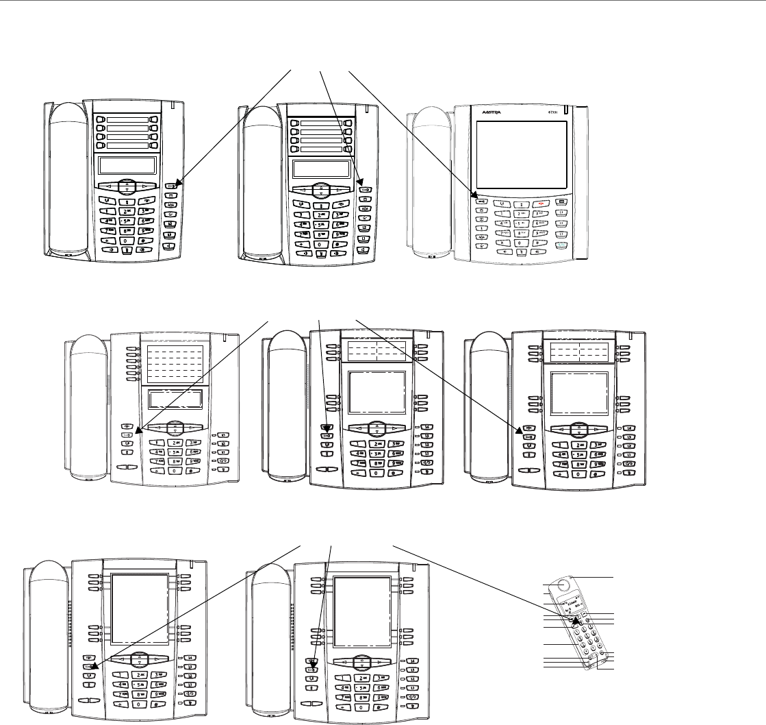
Configuration Methods
2-4 41-001343-02 REV04 – 05.2014
6753i 6755i
6757i/6757i CT
1
2
3
4
5
6
7
8
15
9
10
5
11
12
13
15
14
16
Options Key
Options Key
Options Key
6730i 6731i 6739i
6757i CT Handset
6735i
6737i
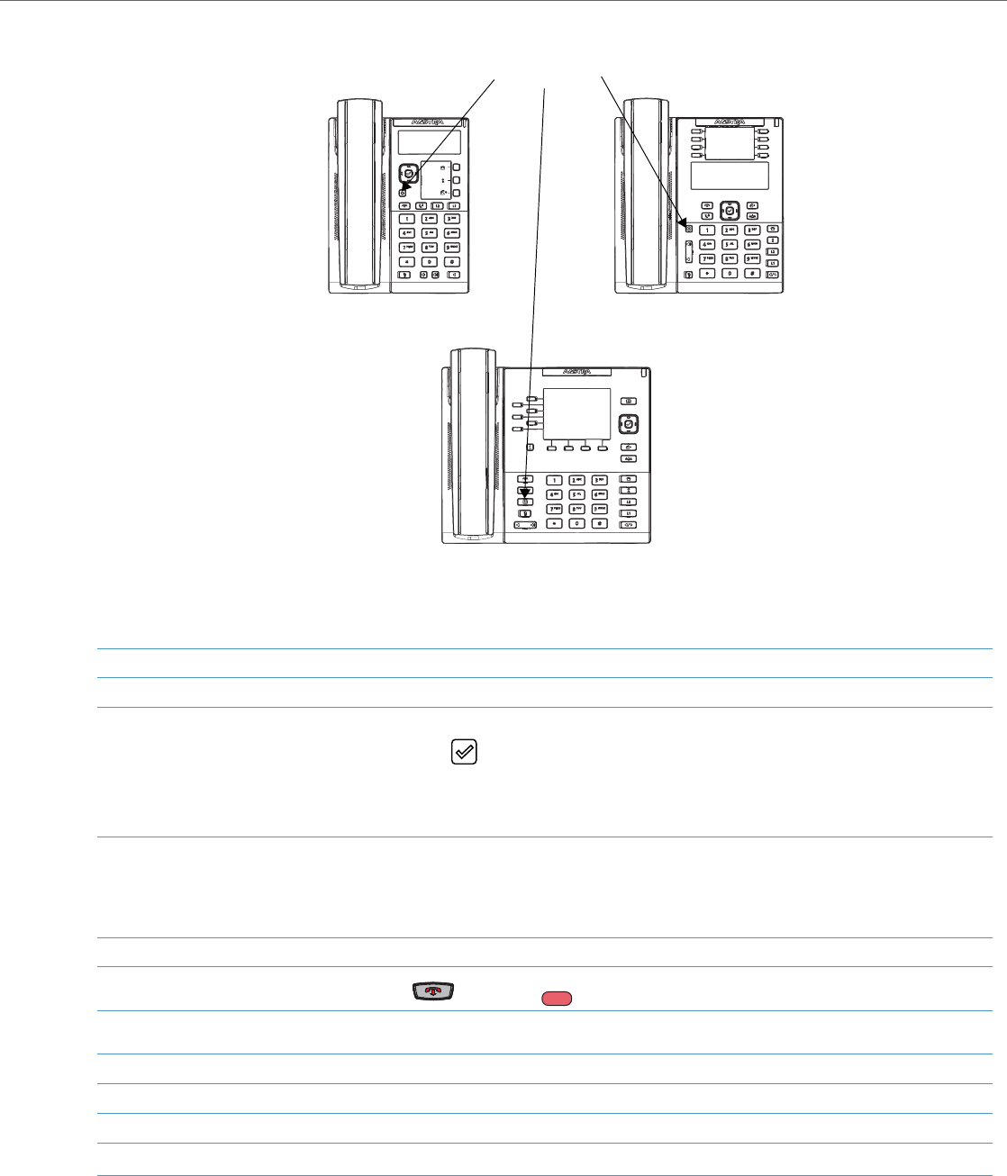
Configuration Methods
41-001343-02 REV04 – 05.2014 2-5
Using the Options Key
From the CT handsets:
1. Press the Options key on the phone to enter the Options List.
2. Use the 5 and2 to scroll through the list of options.
3. On 3-line LCD phones:
To select an option, press the Enter softkey, the button (if applicable), or select the number on the keypad that corresponds to the
option in the Option List.
On 8 and 11-line LCD phones:
To select an option, press the Select softkey, press 4, or select the number on the keypad that corresponds to the option in the Option List.
4. On 3-line LCD phones:
Use the Set softkey after making a change to an option, to save the change.
On 8 and 11-line LCD phones:
Use the Change softkey to change a selected option.
5. Press the Done softkey at any time to save the changes and exit the current option.
6. Press the Cancel softkey, press 3, press , or press any time to exit without saving changes.
1. Press the  key to enter the Options List when the phone is not in use.
2. Use the scroll keys  and Ï to scroll the options.
3. To select and change an option, press the r keys.
4. Press y when done.
6865i
6867i
6863i
Options Key
G
ood
oodbye
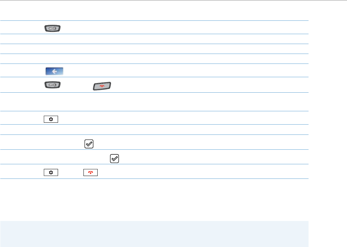
Configuration Methods
2-6 41-001343-02 REV04 – 05.2014
Using the Options Key on the 6739i
Using the Options Key on the 6867i
Aastra Web UI
An administrator can setup and configure the IP phone using the Aastra Web UI. The Aastra Web UI supports Internet
Explorer and Gecko engine-based browsers like Firefox, Mozilla or Netscape.
1. Press the key on the phone to enter the Options List. A list of buttons display.
2. Press an option button to display a list of additional options.
3. Press a button to display the values for a selection or to display additional options.
4. Press a value to set the option on your phone.
5. Press the to return to the previous screen.
6. Press the button or the button at any time to return to the idle screen.
1. Press the key on the phone to enter the Options List.
2. Use the 3and 4 to scroll through the list of options.
3. To select an option, press the button or Select softkey.
4. Change your desired settings and use the button or Save softkey to apply and save your changes.
5. Press the key or the key at any time to return to the idle screen.
Note:
An Administrator can enable or disable the Aastra Web UI for a single phone or all phones in a network. For more infor-
mation about enabling/disabling the Aastra Web UI, see “Enabling/Disabling the Aastra Web UI” on page2-14.

Configuration Methods
41-001343-02 REV04 – 05.2014 2-7
HTTP/HTTPS Support
The Aastra Web UI supports both Hypertext Transfer Protocol (HTTP) and Hypertext Transfer Protocol over Secure Socket
Layer (HTTPS) client and server protocols.
HTTP is the set of rules for transferring files (text, graphic images, sound, video, and other multimedia files) over the Inter-
net. When you open your Web browser, you are indirectly making use of HTTP. HTTP is an application protocol that runs on
top of the TCP/IP suite of protocols (the foundation protocols for the Internet).
HTTPS is a Web protocol that encrypts and decrypts user page requests as well as the pages that are returned by the Web
server. HTTPS uses Secure Socket Layer (SSL) or Transport Layer Security (TLS) as a sublayer under its regular HTTP applica-
tion layering. SSL is a commonly-used protocol for managing the security of a message transmission on the Internet. It
uses a 40-bit key size for the RC4 stream encryption algorithm, which is considered an adequate degree of encryption for
commercial exchange. TLS is a protocol that ensures privacy between communicating applications and their users on the
Internet. When a server and client communicate, TLS ensures that no third party may eavesdrop or tamper with any mes-
sage. TLS is the successor to SSL.
HTTP/HTTPS Client and Server Support
The Aastra IP phones allow for HTTP request processing and associated data transfers to perform over a secure connection
(HTTPS). The IP phones support the following:
•Transfer of firmware images, configuration files, script files, and web page content over a secure connection.
•Web browser phone configuration over a secure connection
•TLS 1.0or SSL 3.0 methods for both client and server
HTTPS Client
When an HTTPS client opens and closes its TCP socket, the SSL software respectively handshakes upon opening and dis-
connects upon closing from the HTTPS server. The main HTTPS client functions are:
•Downloading of configuration files and firmware images
•Downloading of script files based on an “HTTPS://” URL supplied by a softkey definition
HTTPS Server
The HTTPS server provides HTTP functionality over secure connections. It coexists with the HTTP server but has its own set
of tasks. The main HTTPS server functions are:
•Delivery of web page content to a browser client over a secure connection
•Execution of HTTP GET and POST requests received over a secure connection
Non-Blocking HTTP Connections
The IP Phones support a non-blocking HTTP connection feature. This feature allows the user to continue using the phone
when there is a delay during an HTTP connection while the phone is waiting for the HTTP server to respond. This feature
also allows a user to abort the connection and perform other operations on the phone (which will abort the HTTP connec-
tion automatically). A user can also abort the HTTP loading by pressing the GOODBYE key while the phone is displaying
“Loading Page.......”.
Note:
HTTPS uses port 443 instead of HTTP port 80 in its interactions with the TCP/IP lower layer. Both the HTTP and HTTPS
port numbers are configurable using the configuration files, the IP Phone UI, the Aastra Web UI and DHCP Option 66.
For more information about configuring these ports, see Chapter 4, the section, “Configuring the Configuration Server
Protocol” on page4-87.
Note:
This feature impacts only the HTTP calls triggered by a phone key (softkey or programmable key); the HTTP calls per-
formed by action URIs are still blocking.

Configuration Methods
2-8 41-001343-02 REV04 – 05.2014
Authentication Support for HTTP/HTTPS Download Methods for Broadsoft Client Management System (CMS)
The IP Phones have authentication support as referenced in RFC 2617 when using HTTP or HTTPS as download proto-
cols. If a 5i Series phone is challenged by an HTTP or HTTPS server when the server attempts to download the aastra.cfg
file, the phone automatically sends "aastra" as the default Username and Password back to the server. For more informa-
tion about this feature, see Chapter 5, the section, “Authentication Support for HTTP/HTTPS Download Methods, used
with Broadsoft Client Management System (CMS)” on page5-272.
Using HTTPS via the Aastra Web UI
HTTPS is enabled by default on the IP phones. When you open a browser window and enter an IP address or host name
for a phone using HTTP, a server redirection occurs which automatically converts an HTTP connection to an HTTPS con-
nection. After the redirection, a “Security Alert” certificate window displays alerting the user that information exchanged
with the phone cannot be viewed or changed by others. Accepting the certificate then forwards you to the phone’s Web
UI.
Reference
For more information on configuring the HTTPS protocol, see Chapter 4, the sections:
•“Configuring the Configuration Server Protocol” on page4-87
•“HTTPS Client/Server Configuration” on page4-33
Notes:
•The private key and certificate generate outside the phone and embed in the phone firmware for use by the HTTPS
server during the SSL handshake.
•Using the configuration files, the IP phone UI, or the Aastra Web UI, you can configure the following regarding HTTPS:
- Specify HTTPS security client method to use (TLS 1.0 or SSL 3.0)
- Enable or disable HTTP to HTTPS server redirect function
- HTTPS server blocking of XML HTTP POSTS to the phone
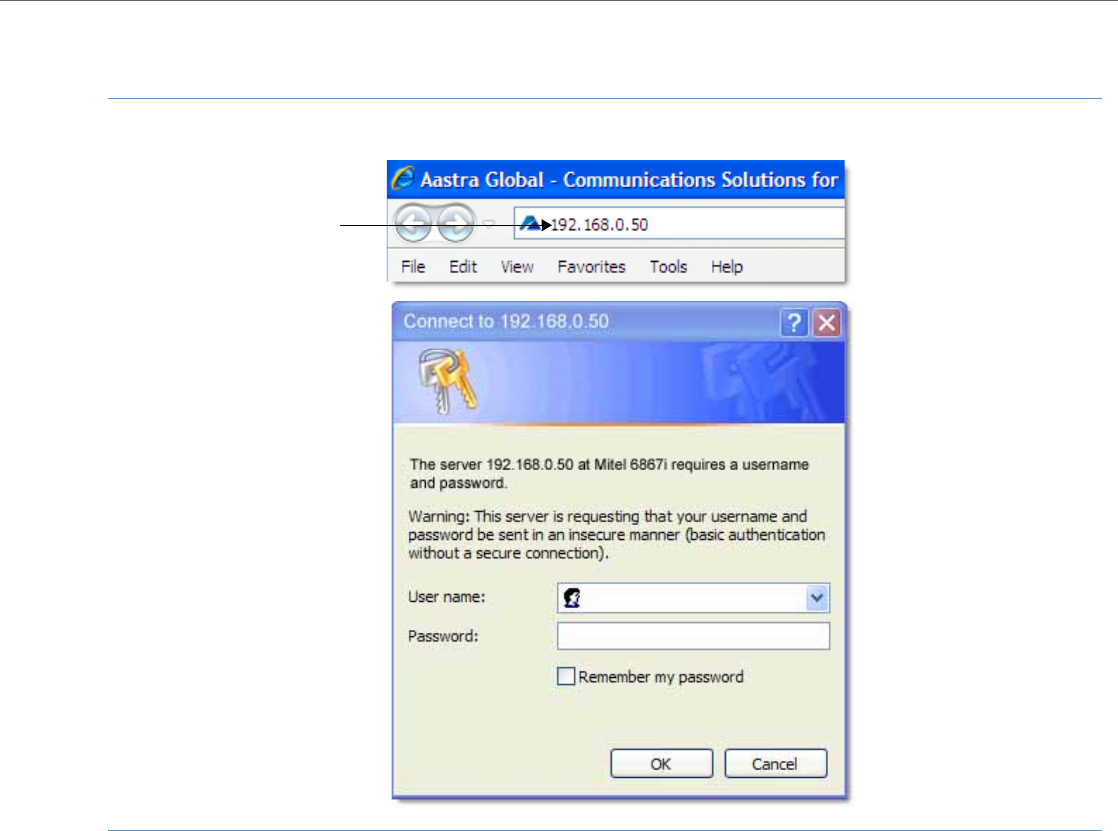
Configuration Methods
41-001343-02 REV04 – 05.2014 2-9
Accessing the Aastra Web UI
Use the following procedure to access the Aastra Web UI.
1. Open your web browser and enter the phone’s IP address or host name into the address field.
The following is an example of the Login screen that displays.
IP address or
host name
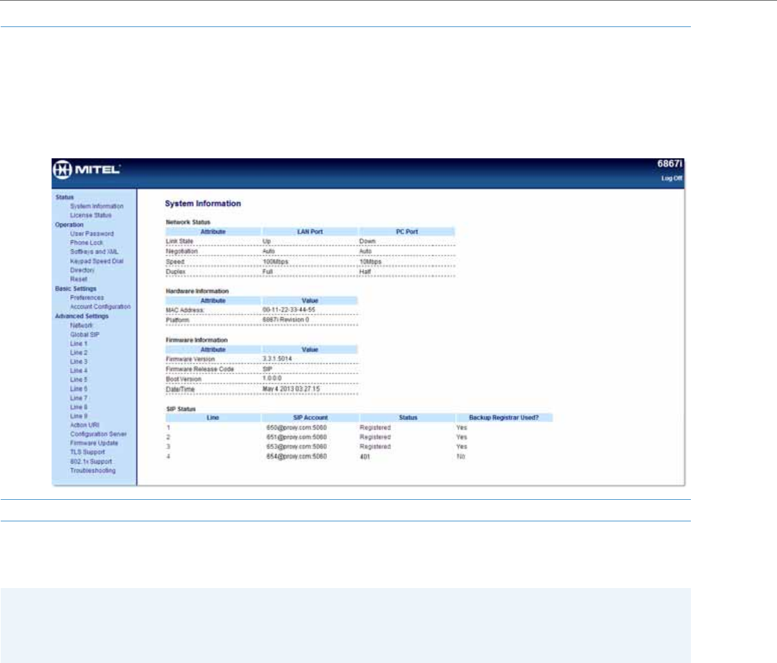
Configuration Methods
2-10 41-001343-02 REV04 – 05.2014
Depending on the model phone you are accessing, the following categories display in the side menu of the Aastra Web
UI: Status, Operation, Basic Settings, Advanced Settings.
Status
The Status section displays the network status and the MAC address of the IP phone. It also displays hardware and
firmware information about the IP phone. The status window also displays the SIP Account information for each account
on the phone. The information in the Status window is read-only.
2. Enter your username and password and click OK.
Note:
For an administrator, the default username is “admin” and the password is “22222”.
For a user, the default username is “user” and the password field is left blank.
The IP phones accept numeric passwords only.
The Status window displays for the IP phone you are accessing. The following illustration is an example of a Status screen for the 6867i IP
phone.
3. You can logout of the Aastra Web UI at any time by clicking Log Off.
Note:
Programmable Keys apply to the 9143i, 6730i, 6731i, 6735i, 6753i, 6755i, 6863i, and 6865i. Softkeys apply to the 9480i,
9480i CT, 6735i, 6737i, 6739i, 6755i, 6757i, 6757i CT, and 6867i. Expansion Modules apply to the 6735i, 6737i, 6739i,
6753i, 6755i, 6757i, 6757i CT, 6865i, and 6867i only.

Configuration Methods
41-001343-02 REV04 – 05.2014 2-11
Operation
The Operation section provides the following options:
Heading Description
User Password Allows you to change user password.
(Applicable to User and Administrator)
Phone Lock Allows you to assign an emergency dial plan to the phone, lock the phone to prevent any changes to the phone
and to prevent use of the phone, and reset the user password.
Note:
You can also configure a softkey to use for locking/unlocking the phone.
(Applicable to User and Administrator)
Softkeys and XML 9480i/9480i CT - 6 state-based, multi-functional softkeys
6735i - 6 Bottom, state-based, multi-functional softkeys
6737i - 6 Top, multi-functional, static softkeys / 6 Bottom, state-based, multi-functional softkeys
6755i - 6 Bottom, state-based, multi-functional softkeys
6739i - 55 state-based, multi-functional softkeys
6757i/6757i CT - 6 Top, multi-functional, static softkeys / 6 Bottom, state-based, multi-functional softkeys
6867i - 6 Top, multi-functional, static softkeys / 4 Bottom, state-based, multi-functional softkeys
(Applicable to User and Administrator)
Programmable Keys 9143i - 7 multi-functional programmable keys
6730i - 8 Top, multi-functional programmable keys
6731i - 8 Top, multi-functional programmable keys
6735i - 6 Top, multi-functional programmable keys
6753i - 6 Top, multi-functional, programmable keys
6755i - 6 Top multi-functional, programmable keys
6863i - 3 multi-functional, programmable keys
6865i - 8 multi-functional, programmable keys
(Applicable to User and Administrator)
Expansion Module <N> The M670i has up to 36 configurable keys. The M675i has up to 60 configurable keys. The M680i has up to 16 con-
figurable keys. You can have up to 3 expansion modules attached to a single phone allowing you to configure
keys for Expansion Module 1, Expansion Module 2, and Expansion Module 3. See your <Model-Specific> IP Phone
User Guide for applicable expansion modules for your model phone.
Note:
Expansion Modules apply to the 6735i, 6737i, 6739i, 6753i, 6755i, 6757i, 6757i CT, 6865i, and 6867i only.
(Applicable to User and Administrator)
Handset Keys
(9480i CT and 6757i CT only) Allows you to configure up to 15 softkeys on the handset.
(Applicable to User and Administrator)
Keypad Speed Dial Allows you to configure up to 9 speed dial keys. These fields map to the keypad digits 1 through 9 on the phone.
You can also configure additional speed dials on the programmable keys, softkeys and expansion modules. See
your <Model-Specific> IP Phone User Guide for more information about this feature.
(Applicable to User and Administrator)
Directory Allows you to copy the Callers List and Directory List from your IP phone to your PC.
(Applicable to User and Administrator)
Reset Allows you to restart the IP phone when required. (Applicable to User and Administrator).
This setting also allows you to set the IP phone back to its factory default settings or remove the local configura-
tion. (Applicable Administrator only)

Configuration Methods
2-12 41-001343-02 REV04 – 05.2014
Basic Settings
The Basic Settings section provides the following options:
Heading Description
Preferences Allows you to set the following General specifications on the IP phone.
•Local Dial Plan (Admin Only)
•Send Dial Plan Terminator (Admin Only)
•Digit Timeout (Admin Only)
•Park Call
•Pick Up Parked Call
•Display DTMF Digits
•Play Call Waiting Tone
•Stuttered Dial Tone
•XML Beep Support
•Status Scroll Delay (seconds)
•Switch UI Focus to Ringing Line
•Call Hold Reminder During Active Calls
•Call Hold Reminder
•Call Waiting Tone Period
•Preferred Line
•Preferred Line Timeout (seconds)
•Goodbye Key Cancels Incoming Call
•Message Waiting Indicator Line
•DND Key Mode
•Call Forward Key Mode
This section also allows you to set:
•Outgoing Intercom Settings (Admin Only; Administrator can enable these for a User if required)
•Incoming Intercom Settings
•Group Paging RTP Settings
•Key Mapping (Admin Only)
•Ring Tones
•Priority Alert Settings (Admin Only)
•Directed Call Pickup Settings (Admin Only)
•Auto Call Distribution Settings (Admin Only)
•Time and Date Settings
•Language Settings (Only the Admin can specify the language pack names to load to the phone). Both the Admin
and User can select the language type to display for the Web UI.
Account Configuration Allows you to configure DND (Do Not Disturb) and/or Call Forwarding by specific account or by all accounts. Also
allows you to enable/disable specific states for each account, specify different phone numbers for call forwarding,
and specify number of rings for a “No Answer” state.

Configuration Methods
41-001343-02 REV04 – 05.2014 2-13
Advanced Settings (Applicable to Administrator Only)
The Advanced Settings section provides the following options:
Heading Description
Network Allows you to set Basic Network Settings, Advanced Network Settings, HTTPS Settings, Type of Service DSCP, and
VLAN settings.
Global SIP Allows you to set global Basic SIP Authentication Settings, Basic SIP Network Settings, Advanced SIP Settings, Real-
time Transport Protocol (RTP) settings, Codec Preference List Settings, and Autodial Settings that apply to all lines on
the IP phone.
Lines 1 through 9 Allows you to set per-line Basic SIP Authentication Settings, Basic SIP Network Settings, Advanced SIP Settings, Real-
time Transport Protocol (RTP) settings, and Autodial Settings that apply to specific lines on the IP phone.
Action URI Allows an administrator to specify a uniform resource identifier (URI) that triggers a GET when certain events occur.
An Administrator can also specify a URI to be called, enable polling for the URI, and specify the interval between
polls.
(Applicable to Administrator Only)
Configuration Server Allows you to set the protocol to use on the configuration server (TFTP (default), FTP, HTTP, or HTTPS), configure
automatic firmware and configuration file updates, enable/disable auto-resync, and assign an XML push server list.
(Applicable to Administrator Only)
Firmware Update Allows you to manually perform a firmware update on the IP phone from the configuration server using any of the
IP Phones supported protocols.
(Applicable to Administrator Only)
TLS Support Allows you to specify SIP Root and Intermediate Certificate files, local certificate files, private key filename, and/or
trusted certificate filename to use when the phone uses the TLS transport protocol to setup a call.
(Applicable to Administrator Only)
802.1x Support Allows you to enable/disable the 802.1x Protocol (Extensible Authentication Protocol (EAP)) to use on the IP phones
for authentication purposes. Applicable choices are EAP-MD5 or EAP-TLS.
(Applicable to Administrator Only)
Troubleshooting Allows you to perform troubleshooting tasks whereby the results can be forwarded to Aastra Technical Support for
analyzing and troubleshooting. Also displays error messages if applicable.
Note:
You can also specify whether a user can upload system information automatically or manually by configuring a
parameter in the configuration files. For more information on this feature, see Chapter 9, the section“Configuration
and Crash File Retrieval” on page9-9.
(Applicable to Administrator Only)

Configuration Methods
2-14 41-001343-02 REV04 – 05.2014
Enabling/Disabling the Aastra Web UI
The Aastra Web UI is enabled by default on the IP phones. A System Administrator can disable the Aastra Web UI on a sin-
gle phone or on all phones if required using the configuration files.
System Administrators can also disable Users ability to login to the Aastra Web UI. With the Aastra Web UI disabled, users
will still be able to lock/unlock the phone with a PIN from the IP Phone. Administrators can disable the user Web UI using
the configuration file. System Administrators have the option to either disable the Web UI for both the Administrator and
User, enable for both the Administrator and User, or enable the Web UI only for the Administrator.Use the following pro-
cedure to enable and disable the Aastra Web UI.
To Disable the Aastra Web UI:
Configuration Files (Administrator Only)
A system administrator can enter specific parameters in the configuration files to configure the IP phones. All parameters
in configuration files can only be set by an administrator.
You can enter specific configuration parameters in either of the following configuration files:
•aastra.cfg
•<model>.cfg
•<mac>.cfg
References
For information about configuration file precedence, see Chapter 1, “Overview.”
For a description of each configuration file parameter, see AppendixA, “Configuration Parameters.”
Using the Configuration Files
When you use the configuration files to configure the IP phones, you must use a text-based editing application to open
the configuration file (aastra.cfg, <model>.cfg, or <mac>.cfg).
Use the following procedure to add, delete, or change parameters and their settings in the configuration files.
Configuration Files
1. Using a text-based editing application, open the <mac>.cfg file if you want to disable the Web UI on a single phone. Open the aastra.cfg
file to disable the Web UI on all phones
2. Enter the following parameter:
web interface enabled: 0
Note:
A value of zero (0) disables the Web UI on the phone for Administrators and Users. A value of (1) enables the Web UI for Administrators and
Users. A value of (2) enables the Web UI for administrators only.
3. Save the changes and close the <model>.cfg, <mac>.cfg or the aastra.cfg file.
4. Restart the phone to apply the changes. The Aastra Web UI is disabled for a single IP phone or for all phones.
Note:
Apply this procedure wherever this Administrator Guide refers to configuring parameters using the configuration files.

Configuration Methods
41-001343-02 REV04 – 05.2014 2-15
Locking Parameters in the Configuration File
The IP Phones allow you to lock individual configuration parameters to prevent an end user from changing the configura-
tion on the phone. This feature allows service providers to prevent the end-user from changing the values of specific
parameters that would affect the service they provide.
An Administrator can lock parameters on the phone by placing an exclamation mark (!) before the parameter in the con-
figuration file. For example,
!admin password: 22222
!emergency dial plan: 911|999
You can lock parameters on the phone using the configuration files. Once the parameters are locked, they cannot be
changed at all during the phones run-time. The parameters appear as read-only when accessing the Aastra Web UI and
the IP Phone UI. In the Aastra Web UI, they appear grayed out. In the IP Phone UI the ability to change the parameters is
removed. In addition, when parameters are locked, they cannot be changed via XML.
Limitations
•A User possessing the Administrator password can bypass the locking of configuration server details by defaulting the
phone.
•Softkeys can be locked and unlocked via XML in Release 3.3.1 and up using the AastraIPPhoneConfiguration object
and softkeyN locked parameter (for more information about using the AastraIPPhoneConfiguration object, contact
Aastra Customer Support regarding the Aastra XML Development Guide). All other parameters cannot be locked or
unlocked using XML.
•Configuration files that include locked parameters are not backwards compatible.
Overwriting Parameters with Defaults in the Configuration Files
An Administrator can specify a “ ^ “ (caret character) before a configuration parameter in the aastra.cfg, <model>.cfg, and
<mac>.cfg configuration files, which allows the parameter to be overwritten and reset back to a specified value. This can
be convenient when changes are made by a user to specific parameters on the phone locally (via Aastra Web UI or IP
Phone UI), and the Administrator wants to set the parameters back to the default values using the configuration files.
Configuration Files
1. Using a text-based editing application, open the configuration file for the phone, for which you want to configure the directory list (either
aastra.cfg, <model>.cfg, <mac>.cfg or all three).
2. Enter the required configuration parameters followed by the applicable value. For example,
directory 1: company_directory
directory 2: my_personal_directory
3. Save the changes and close the configuration file.
4. If the parameter requires the phone to be restarted in order for it to take affect, use the IP Phone UI or the Aastra Web UI to restart the
phone.
Notes:
•The “parameter locking” feature applies to Release 2.4 and up. Any phones that have a previous release loaded on the
phone will not be able to use the locking functionality in the configuration file.
•Any parameter duplicated in the <model>.cfg from the aastra.cfg is overwritten by the locking status and the value
of the parameter found in the <model>.cfg file. Parameters in the <mac>.cfg file overwrite parameters in the
<model>.cfg and aastra.cfg files.

Configuration Methods
2-16 41-001343-02 REV04 – 05.2014
As an example, the following table describes how the parameter “sip proxy ip” is handled by the phone during phone
bootup when either the “ ^ “ (default parameter) is used or the “ ! “ (locked parameter) is used.
Example 1
The following example illustrates the use of the “ ^ “ in the configuration files.
aastra.cfg
^sip proxy ip: pbx.company.com
^sip proxy port: 5060
^sip registrar ip: pbx.company.com
^sip registrar port: 5060
In the above example, if an Administrator indicates the “ ^ “ before the parameters in the aastra.cfg file, and then loads
the aastra.cfg file to the phone, these four parameters are reset to their default values, even if the parameters were previ-
ously changed on the phone.
Example 2
The following example illustrates the use of the “ ^ “ and “!” in the configuration files.
aastra.cfg
^sip proxy ip: pbx.company.com
^sip proxy port: 5060
^sip registrar ip: pbx.company.com
^sip registrar port: 5060
<model>.cfg
!sip proxy ip: pbx.aastra.com //this parameter is locked
!sip proxy port: 5062 //this parameter is locked
!sip registrar ip: pbx.aastra.com //this parameter is locked
!sip registrar port: 5062 //this parameter is locked
<mac>.cfg
sip proxy port: 5064 //this parameter is unlocked
sip registrar port: 5064 //this parameter is unlocked
IF THEN
new <mac>.cfg file is loaded to the phone with “^sip proxy ip” and any
other parameter(s) from the file specifying a “ ^ “ the “^sip proxy ip” and any other “ ^ “ parameters are overwritten if pre-
viously changed by the user.
new <model>.cfg file is loaded to the phone with “^sip proxy ip” and any
other parameter(s) from the file specifying a “ ^ “ the “^sip proxy ip” and any other “ ^ “ parameters are overwritten if pre-
viously changed by the user.
new aastra.cfg file is loaded to the phone with “^sip proxy ip” and any
other parameter(s) from the file specifying a “ ^ “ the “^sip proxy ip” and any other “ ^ “ parameters are overwritten if pre-
viously changed by the user.
the first instance is “^sip proxy ip” and second instance is “!sip proxy ip”
in the aastra.cfg, <model>.cfg, and/or <mac>.cfg file, the value for the second instance of the parameter (“!sip proxy ip”) over-
writes to the aastra.cfg, <model>.cfg, and/or <mac>.cfg files previously on
the phone.
Notes:
•XML reboots take precedence over server.cfg values. Therefore, “ ^ “ parameters are ignored in the aastra.cfg file
during XML reboots.
•If a parameter has both a “ ^ “ and a “ ! “ preceding the same parameter (i.e., ^!sip proxy ip: pbx.company.com), then
theparameter is ignored and NOT overwritten.

Configuration Methods
41-001343-02 REV04 – 05.2014 2-17
With this configuration, on the Web UI, the "sip proxy ip" and "sip registrar ip” parameters cannot be modified (they are
grayed out), and the value is "pbx.aastra.com" since <model>.cfg has overwritten aastra.cfg.
The "sip proxy port" and "sip registrar port" parameters can be modified through Web UI because <mac>.cfg has over-
written <model>.cfg and aastra.cfg. On the Web UI, the value for these parameters is 5064.
Configuration Server Redundancy via DNS A Records
The phone sends a DNS query and in the DNS response, it accepts the first server IP address and contacts that server,
ignoring any additional IP addresses in the response. This allows service providers to manage load balancing (via the DNS
server putting different records first on each request), but does not provide redundancy.
The phones also provide support of multiple IP addresses being returned for the DNS lookup for server redundancy via
multiple DNS A record entries. The phone tries to contact the first server address it receives, but if this fails, it now tries to
contact the second server address, etc.
This feature supports all the download protocols (TFTP, FTP, HTTP, and HTTPS).
Limitation
In certain cases, the TFTP Protocol cannot distinguish between “server down” and “no file on server” error messages;
therefore, the failover in these instances may fail.
Notes:
•Once the phone has failed over to a redundant server, it continues to use that server for all other server-related proc-
esses on the phone (i.e., firmware upgrades from the Web UI, boot-up process, etc.).
•If a server fails while downloading a file(s) to the phone, the phone performs the discovery process of finding a
redundant server that is available. When the boot is complete on the redundant server, the phone tries to download
the file(s) again from the previous server. The check-sync process also performs the same way when a server fails.
•The “Skip” softkey displays in the event of a network outage, the user can skip the configuration download and con-
tinue the boot.
•All server failovers and failed server IP addresses are logged in the “Error Messages” page on the IP Phone UI at
Options->Phone Status->Error Messages.

3-1 41-001343-02 REV04 – 05.2014
Chapter 3
Administrator Options
About this Chapter
The IP phones provide specific options on the IP Phone that only an Administrator can access. These options are pass-
word protected and allow an Administrator to change or set features and configuration information as required. For all
models, an Administrator can use the IP Phone UI, the Aastra Web UI, or the configuration files to enter and change val-
ues.
This chapter provides information about the available Administrator options.
Topics
This chapter covers the following topics:
Note:
Specific options are configurable only via the IP Phone UI, and/or Aastra Web UI, and/or configuration files.
Topic Page
Administrator Level Options page3-2
IP Phone UI Options page3-2
Aastra Web UI Options page3-6
Configuration File Options page3-8
Phone Status page3-8
Restarting Your Phone page3-11
Set Phone to Factory Defaults/Erase Local Configuration page3-13
Basic Settings page3-16
Account Configuration page3-27
Network Settings page3-27
Line Settings page3-44
Softkeys, Programmable Keys, Expansion Module Keys page3-45
Action URI page3-46
Configuration Server Settings page3-47
Firmware Update Features page3-51
TLS Support page3-51
802.1x Support page3-54
Troubleshooting page3-55

Administrator Level Options
41-001343-02 REV04 – 05.2014 3-2
Administrator Level Options
Description
There are options on the IP phone that both a User and Administrator can access. However, there are specific options that
an Administrator can access only. These options allow the Administrator to configure and manage local and/or remote IP
phones in a network.
An Administrator can access and manage these options using the IP Phone UI, the Aastra Web UI, or the configuration files.
IP Phone UI Options
Using the IP Phone UI, you can access the Administrator options at Options->Admin Menu using the default password of
"22222"
The following are administrator options in the "Options List" on all IP phones EXCEPT the 6739i and 6867i:
•Administrator Menu
–Configuration Server
–SIP Settings
–Network Settings
–Factory Default
–Erase Local Config
The 6739i uses graphical icons to display the Administrator (Advanced) options on the 6739i phone, as shown in the fol-
lowing illustration.
6739i Aastra IP Phone Administrator Menu
Options List 12 : 45pm
Mon Jan 1
Audio
Softkeys Status Advanced Password
Restart
Display Set Time Language
Bluetooth
Lock
Live Dial
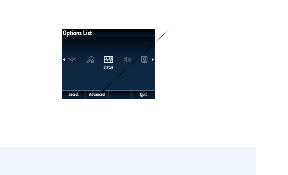
Administrator Level Options
3-3 41-001343-02 REV04 – 05.2014
The 6867i has an “Advanced” softkey, which when pressed gives access to the Administrator options.
The following are administrator options in the "Options List" on the 6739i and 6867i:
•Advanced Menu
–Configuration Server
–SIP Settings
–Network Settings
–Reset (includes options for “Erase Local Config” and “Factory Default”)
References
For information about all other user options in the “Options Menu”, see your <Model-Specific> IP Phone User Guide.
For procedures on configuring Administrator Options on the IP phone via the IP phone UI, see:
•Chapter 4, “Configuring Network and Session Initiation Protocol (SIP) Features”
•Chapter 5, “Configuring Operational Features”
•Chapter 6, “Configuring Advanced Operational Features”
Note:
An administrator has the option of enabling and disabling the use of password protection on the IP phone UI for all
model phones. This is configurable using the configuration files only. For more information about this feature, see
Appendix A, the section “Password Settings” on page A-14
6867i Aastra IP Phone Administrator Menu

Administrator Level Options
41-001343-02 REV04 – 05.2014 3-4
Simplified IP Phone UI Options Menu
An Administrator can replace the existing options menu on the Phone UI with a more simplified options menu. In the con-
figuration files, the “options simple menu” parameter allows you to display either the full menu (if set to 0), or the simpli-
fied menu (if set to 1). The following table illustrates the differences between the full menu and the simplified menu.
For all model phones EXCEPT the 6739i and 6867i:
For the 6739i:
Note:
When setting the “options simple menu” parameter, the menu changes in the Phone UI only. The Aastra Web UI is not
affected.
Full Options Menu Simplified Options Menu
Call Forward Call Forward
Preferences Preferences
Phone Status Phone Status
Password Removed
Administrator Menu Removed
Restart Phone Accessible through Phone Status
Phone Lock Phone Lock
Full Options Menu Simplified Options Menu
Audio Audio
Display Display
Set Time Removed
Language Removed
Bluetooth Bluetooth
Softkeys Removed
Status Status
Advanced Removed
Password Removed
Restart Accessible through Status
Lock Lock

Administrator Level Options
3-5 41-001343-02 REV04 – 05.2014
For the 6867i:
Configuring the Simplified IP Phone UI Options Menu
You can enable the simplified IP Phone UI Options menu using the configurations files only.
Full Options Menu Simplified Options Menu
Language Removed
Time and Date Removed
Call Forward Call Forward
Lock Lock (Password Sub-Option Removed)
Status Status
Audio Audio
Display Display
Dialpad Removed
Restart Restart
Warning!
When using the simplified menu, you cannot change the Network settings from the IP Phone UI. If the network settings
become misconfigured, you must “factory default” the phone and use the full menu to recover the network settings
from the Phone UI OR use the Aastra Web UI to configure the network settings.
Configuration Files
For the specific parameter you can set in the configuration files, see Appendix A, the section, “Simplified IP Phone UI
Options Menu” on page A-7.
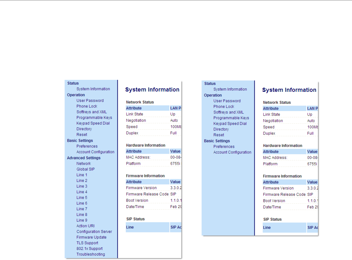
Administrator Level Options
41-001343-02 REV04 – 05.2014 3-6
Aastra Web UI Options
An Administrator can configure specific options using the Aastra Web UI. These options display after an Administrator logs
into the Web UI using a Web browser and entering the Admin username and password at the login prompt (The default
username is "admin" and the default password is "22222". The IP phones accept numeric passwords only.) The column on
the left side of the screen indicates the configurable options. A User has limited configuration options as shown in the fol-
lowing illustrations.
The following are options that an Administrator can configure in the Aastra Web UI (and are not available for the User to
configure):
•Operation->Reset
–Restore to Factory Defaults
–Remove Local Configuration Settings
•Basic Settings->Preferences->General
–Local Dial Plan
–Send Dial Plan Terminator
–Digit Timeout (seconds)
•Basic Settings->Preferences->Outgoing Intercom Settings (User can configure this via the Aastra Web UI if enabled
by an Administrator)
Administrator Web UI Menu User Web UI Menu

Administrator Level Options
3-7 41-001343-02 REV04 – 05.2014
•Basic Settings->Preferences->Key Mapping
•Basic Settings->Preferences->Priority Alerting Settings
•Basic Settings->Preferences->Directed Call Pickup Settings
•Basic Settings->Preferences->Auto Call Distribution Settings
•Basic Settings->Preferences->Language Settings
–Language 1 (entering language pack filename)
–Language 2 (entering language pack filename)
–Language 3 (entering language pack filename)
–Language 4 (entering language pack filename)
•Advanced Settings
–Network
–Global SIP
–Line 1 through 9 Settings
–Action URI
–Configuration Server
–Firmware Update
–TLS Support
–802.1x Support
–Troubleshooting
References
For information about options available to a User AND Administrator in the Aastra Web UI, see your <Model-Specific> IP
Phone User Guide.
For procedures to Restart your phone or restore factory defaults, see “Restarting Your Phone” on page3-11, and “Set
Phone to Factory Defaults/Erase Local Configuration” on page3-13.
For more information about Advanced Settings for the IP Phone, see Chapter 4, “Configuring Network and Session Initia-
tion Protocol (SIP) Features.”
For procedures on configuring the Basic Settings for the IP Phone, see Chapter 5, “Configuring Operational Features.”

Administrator Level Options
41-001343-02 REV04 – 05.2014 3-8
Configuration File Options
An Administrator can enter specific parameters in the configuration files to configure the IP phones. All parameters in con-
figuration files can only be set by an administrator.
References
For a procedure on using the configuration files, see Chapter 2, the section, “Configuration Files (Administrator Only)” on
page2-1.
For a description of each parameter you can enter in the configuration files, see AppendixA, “Configuration Parameters.”
Phone Status
The Phone Status on the IP Phone displays the network status and firmware version of the IP phone.
You can display phone status using the IP phone UI or the Aastra Web UI.
Phone Status via IP Phone UI
In the IP phone UI, the Phone Status options are available to the user and the administrator and do not require a password
entry.
Phone Status All IP Phones Except the 6739i and 6867i
•IP&MAC Addresses
–Displays the IP address and MAC address of the phone.
•LAN Port
–Displays the Link State, Negotiation Method, Speed, and Duplex Method that the phone uses on its LAN port.
•PC Port
–Displays the Link State, Negotiation Method, Speed, and Duplex Method that the phone uses on its PC Port.
•Firmware Info
–Displays information about the firmware and boot version that is currently installed on the IP phone.
•Error Messages
–Displays any error messages that occurred during the phone’s last reboot.
Phone Status for 6739i IP Phone
•Firmware
–Displays information about the firmware and boot version that is currently installed on the IP phone.
•Network
–IP&MAC Addresses
–Displays the IP address and MAC address of the phone.
–LAN Port
–Displays the Link State, Negotiation Method, Speed, and Duplex Method that the phone uses on its LAN port.
–PC Port
–Displays the Link State, Negotiation Method, Speed, and Duplex Method that the phone uses on its PC Port.
•Error Msg
–Displays any error messages that occurred during the phone’s last reboot.
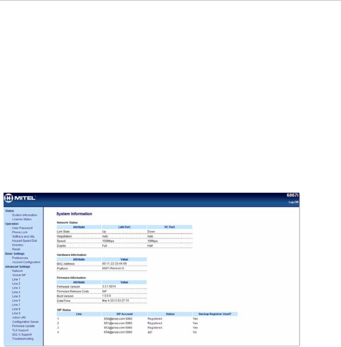
Administrator Level Options
3-9 41-001343-02 REV04 – 05.2014
Phone Status for 6867i IP Phone
•Firmware Info
–Displays information about the firmware and boot version that is currently installed on the IP phone.
•Network
–IP Address
–Displays the IP address of the phone.
–MAC Address
–Displays the MAC address of the phone.
–LAN Port
–Displays the Link State, Negotiation Method, Speed, and Duplex Method that the phone uses on its LAN port.
–PC Port
–Displays the Link State, Negotiation Method, Speed, and Duplex Method that the phone uses on its PC Port.
•Storage
–Displays the number of Directory, Callers, and Redial List entries saved on the phone.
•Error Messages
–Displays any error messages that occurred during the phone’s last reboot.
Phone Status via Aastra Web UI
The first screen that displays after logging into the Aastra Web UI for a phone is the Status screen. This screen also dis-
plays when selecting Status->System Information. The information on this screen is available to the user and the
administrator as read-only.

Administrator Level Options
41-001343-02 REV04 – 05.2014 3-10
The following is a description of the information on the Status screen:
•Network Status
–Displays the network status of the Ethernet ports at the back of the phone. You can also view the phone’s IP and MAC
addresses. Information in this field includes Link State, Negotiation, Speed, and Duplex for Port 0 and Port 1.
•Hardware Information
–Displays the current IP phone platform and the revision number.
•Firmware Information
–Displays information about the firmware that is currently installed on the IP phone. Information in this field includes
Firmware Version, Firmware Release Code, Boot Version, Release Date/Time.
•SIP Status
–Displays information about the SIP registration status of the phone. If there are accounts configured on the IP Phone,
their SIP status displays in this field. All model phones display the status of up to 9 lines.
The following table describes the status conditions that can display for an account(s).
Status Condition Description
Registered Displays this status on accounts that HAVE been registered with the SIP proxy server.
Example:
Backup
Registrar
Line SIP Account Status Used?
1 650@proxy.com:5060 Registered Yes
where
Account Number is “1”
SIP Account is “650@proxy.com” on port “5060”
Status is “Registered”
Backup registrar is used (“Yes”)
SIP Error Number Displays on accounts when registration fails with the SIP proxy server.
Example:
Backup
Registrar
Line SIP Account Status Used?
4 653@proxy.com:5060 401 No
where
Account Number is “4”
SIP Account is “653@proxy.com” on port “5060”
Status is “401” - Unregistered if SIP registration fails.
Backup registrar is used (“No”)
Note:
The IP Phones can register with multiple server using the same user name. So the SIP Status information on the Status
screen may display the same account with different registrar and proxy IP addresses. For more information, see

Administrator Level Options
3-11 41-001343-02 REV04 – 05.2014
Restarting Your Phone
As System Administrator, there may be times when you need to restart a phone. The Restart option allows you reboot
the phone when required. A reset may be necessary when:
•There is a change in your network, OR
•To re-load modified configuration files, OR
•If the settings for the IP phone on the IP PBX system have been modified.
You can restart the phone using the IP Phone UI or the Aastra Web UI.
Restarting the Phone Using the IP Phone UI
IP Phone UI
1. Press the Options key on the phone to enter the Options List.
2. Select Restart Phone.
3. For 3-Line LCD Displays:
Press # to confirm.
Note:
To cancel the Restart, press the 3key.
For 8 and 11-Line LCD Displays:
Press Restart.
Note:
To cancel the Restart, press Cancel.
For the 6739i:
1. Press the Options key on the phone to enter the Options List.
2. Press the Restart button. A “Restart the Phone?” prompt displays.
3. Press Yes to restart the phone, or No to cancel the restart function.
For the 6867i:
1. Press the Options key on the phone to enter the Options List.
2. Navigate to the Restart option and press the button or Select softkey. A “Restart Phone?” prompt displays.
3. Select Yes using the button or press the Restart softkey to restart the phone. Press No using the button or the Cancel softkey
to cancel the restart function.
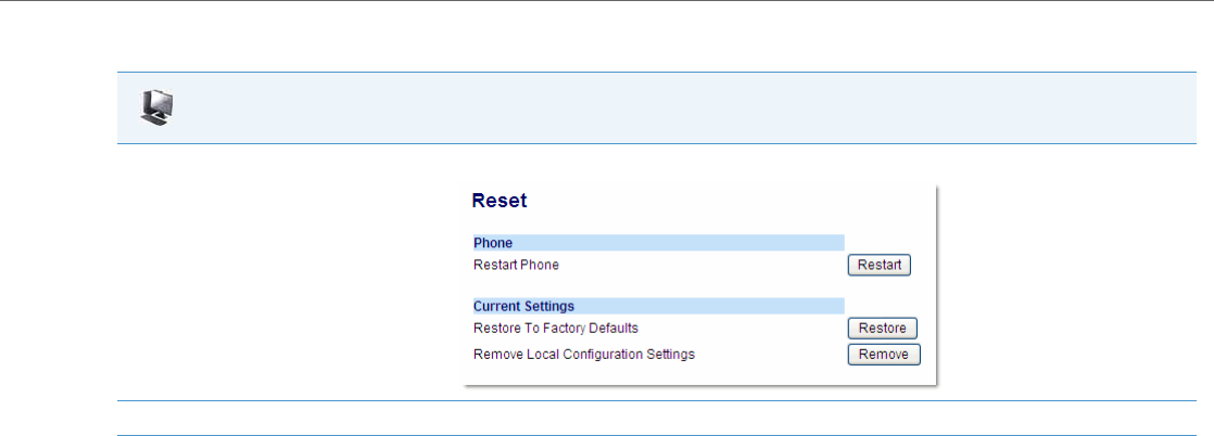
Administrator Level Options
41-001343-02 REV04 – 05.2014 3-12
Restarting the Phone Using the Aastra Web UI
Aastra Web UI
1. Click on Operation->Reset->Phone.
2. Click Restart to restart the phone.
Administrator Level Options
3-13 41-001343-02 REV04 – 05.2014
Set Phone to Factory Defaults/Erase Local Configuration
You can set phones to their factory default setting or remove a local phone’s configuration using the IP Phone UI or the
Aastra Web UI.
Setting Factory Defaults on the Phone
Factory default settings are the settings that reside on the phone after it has left the factory. The factory default settings
on the phone sets the factory defaults for all of the settings in the aastra.cfg, <model>.cfg, <mac>.cfg, and local configu-
ration. Performing this action results in losing all user-modified settings. You can reset a phone to factory defaults using
the IP Phone UI or the Aastra Web UI.
Setting Factory Defaults Using the IP Phone UI
IP Phone UI
1. Press the Options key on the phone to enter the Options List.
2. Select Administrator Menu and enter your Administrator Password (default is 22222).
3. Select Factory Default.
4. For 3-Line LCD Displays:
The “Restore Defaults?” prompt displays.
Press # to confirm.
For 8 and 11-Line LCD Phones:
The “Reset phone to factory defaults?” prompt displays.
Press Default to confirm.
For the 6739i:
1. Press the Options key on the phone to enter the Options List.
2. Press the Advanced button. A keyboard displays.
3. Enter the Administrator password using the keyboard, and press <Enter>. Default is “22222”.
4. Press the Reset button. A “Reset Configuration?” prompt displays.
5. Press the Factory Default button.
The phone immediately resets to factory defaults and the phone reboots.
For the 6867i:
1. Press the Options key on the phone to enter the Options List.
2. Press the Advanced softkey.
3. Enter the Administrator password and press Enter. Default is “22222”.
4. Navigate to the Reset option and press the button or Select softkey.
5. Select Factory Default using the button or press the Select softkey.
The phone immediately resets to factory defaults and the phone reboots.
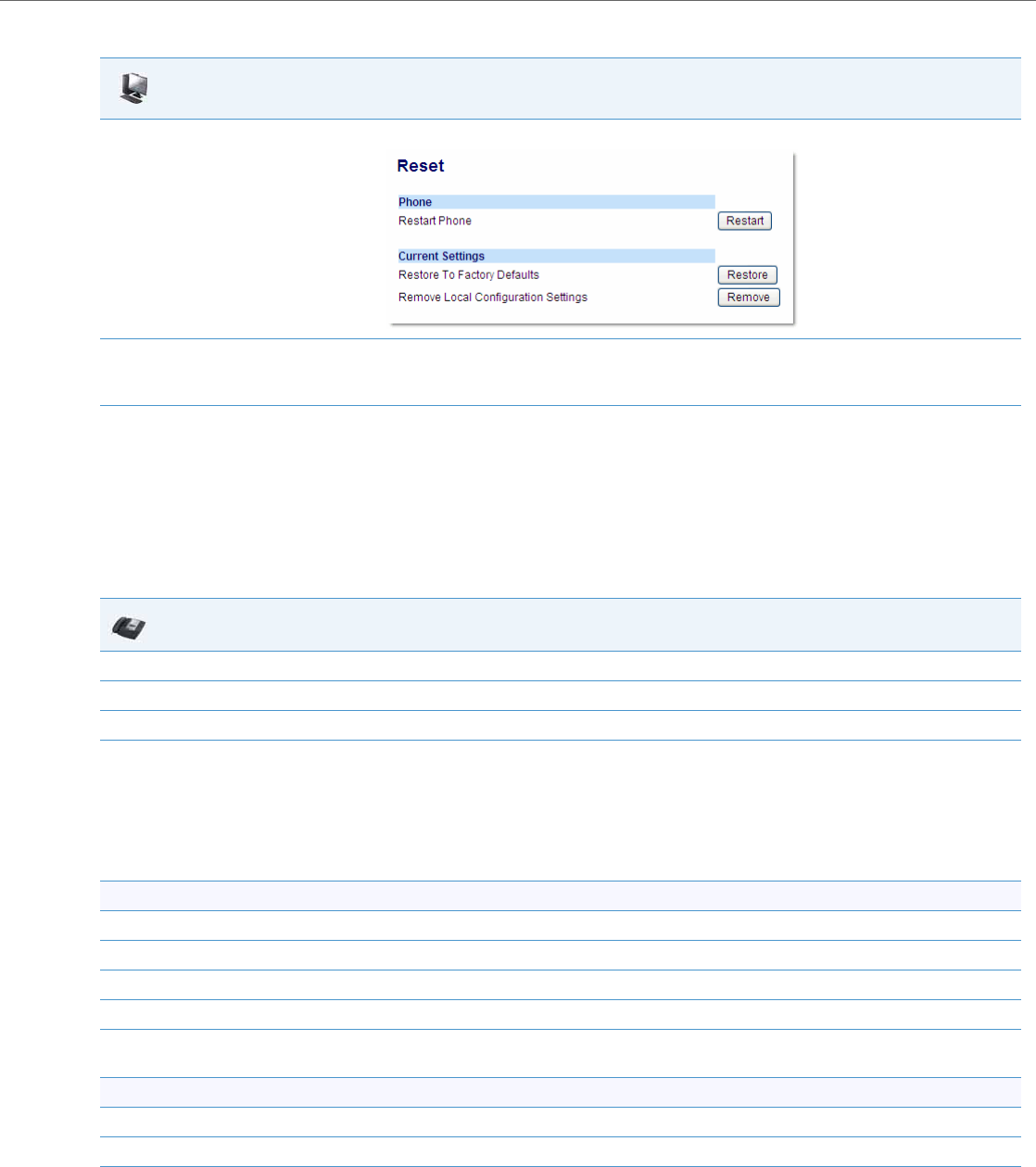
Administrator Level Options
41-001343-02 REV04 – 05.2014 3-14
Settings Factory Defaults Using the Aastra Web UI
Erasing the Phone’s Local Configuration
You can reset the IP Phone’s local configuration if required. The local configuration is the last updated configuration you
performed using the IP Phone UI or the Aastra Web UI. Performing this action results in losing all recently user-modified
settings. For more information about local configuration, see Chapter 1, the section, “Configuration File Precedence” on
page1-51.
Erasing the Phone’s Local Configuration Using the IP Phone UI
Aastra Web UI
1. Click on Operation->Reset->Current Settings.
2. In the "Restore to Factory Defaults" field, click Restore.
This restores all factory defaults, and removes any saved configuration and directory list files.
IP Phone UI
1. Press the Options key on the phone to enter the Options List.
2. Select Administrator Menu and enter your Administrator Password (default is 22222).
3. Select Erase Local Config.
4. For 3-Line LCD Displays:
The “Erase local config?” prompt displays.
Press # to confirm.
For 8 and 11-Line LCD Displays:
The “Erase local config?” prompt displays.
Press Erase to confirm.
For the 6739i:
1. Press the Options key on the phone to enter the Options List.
2. Press the Advanced button. A keyboard displays.
3. Enter the Administrator password using the keyboard, and press <Enter>. Default is “22222”.
4. Press the Reset button. A “Reset Configuration?” prompt displays.
5. Press the Erase Local Cfg. button.
The phone immediately erases the local configuration on the phone and the phone reboots.
For the 6867i:
1. Press the Options key on the phone to enter the Options List.
2. Press the Advanced softkey.
3. Enter the Administrator password and press Enter. Default is “22222”.
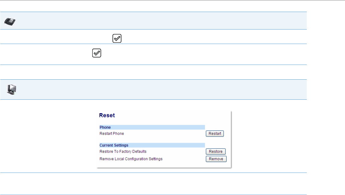
Administrator Level Options
3-15 41-001343-02 REV04 – 05.2014
Erasing the Phone’s Local Configuration Using the Aastra Web UI
4. Navigate to the Reset option and press the button or Select softkey.
5. Select Erase Local Cfg. using the button or press the Select softkey.
The phone immediately erases the local configuration on the phone and the phone reboots.
Aastra Web UI
1. Click on Operation->Reset->Current Settings.
2. In the "Remove Local Configuration Settings" field, click Remove.
This removes the last customized configuration settings made on the phone.
IP Phone UI

Administrator Level Options
41-001343-02 REV04 – 05.2014 3-16
Basic Settings
An Administrator has access to specific Basic Setting options to configure and manage the IP Phone in the network. The
following sections identify the options available to an Administrator only, or where indicated, to a User and Administrator.
These tables also identify whether you can configure them using the Aastra Web UI, IP Phone UI, or the configuration files.
General Settings
Parameter in
Aastra Web UI Parameter in Configuration
Files Description
Local Dial Plan sip dial plan A dial plan that describes the number and pattern of digits that a user dials to reach
a particular telephone number. Dial Plan field accepts up to 512 characters.
For more information on this feature, see “Local Dial Plan” on page5-52.
Send Dial Plan Terminator sip dial plan terminator Specifies whether or not pressing the hash/pound (i.e. "#") key, while performing an
outgoing call on an open line, should be sent as %23 to the proxy in the dial string or
if the key should be used as a dial plan terminator (i.e. dials out the call immediately).
For more information on this feature, see “SIP Dial Plan Terminator” on page5-53.
Digit Timeout sip digit timeout Represents the time, in seconds, to configure the timeout between consecutive key
presses.
For more information on this feature, see. “Digit Timeout” on page5-53.
Park Call
Note:
This option can be set by both
Users and Administrators.
sip lineN park pickup config The parking of a live call to a specific extension.
This feature on the Basic Preferences screen is available on all phones EXCEPT
the 9143i, 6753i, 6863i, and 6865i.
To configure the Park feature on a key, see Chapter 5, the section, “Park/Pick Up Static
and Programmable Configuration” on page5-177.
Pick Up Parked Call
Note:
This option can be set by both
Users and Administrators.
sip lineN park pickup config Picking up a parked call at the specified extension.
This feature on the Basic Preferences screen is available on all phones EXCEPT
the 9143i, 6753i, 6863i, and 6865i.
To configure the Pickup feature on a key, see Chapter 5, the section, “Park/Pick Up
Static and Programmable Configuration” on page5-177.
N/A suppress dtmf playback Enables and disables suppression of DTMF playback when a number is dialed from
the softkeys or programmable keys.
For more information on this feature, see. “Suppressing DTMF Playback” on page5-
55.
Display DTMF Digits
Note:
This option can be set by both
Users and Administrators.
display dtmf digits Enables and disables the display of DTMF digits on the IP phone display during a con-
nected state.
For more information on this feature, see. “Display DTMF Digits” on page5-55.
Play Call Waiting Tone
Note:
This option can be set by both
Users and Administrators.
call waiting tone Enable or disables the playing of a call waiting tone when a caller is on an active call
and a new call comes into the phone.
For more information on this feature, see. “Call Waiting Tone” on page5-58.
Stuttered Dial Tone
Note:
This option can be set by both
Users and Administrators.
stutter disabled Enable or disables the playing of a stuttered dial tone when there is a message wait-
ing on the IP phone.
For more information on this feature, see. “Stuttered Dial Tone” on page5-61.

Administrator Level Options
3-17 41-001343-02 REV04 – 05.2014
XML Beep Support
Note:
This option can be set by both
Users and Administrators.
xml beep notification Enables or disables the playing of a beep to indicate a status on the phone. When the
phone receives a status message, the BEEP notifies the user that the message is dis-
playing.
For more information on this feature, see “XML Beep Support” on page5-62.
Status Scroll Delay (seconds)
Note:
This option can be set by both
Users and Administrators.
xml status scroll delay Allows you to set the time delay, in seconds, between the scrolling of each status
message on the phone.
For more information on this feature, see “Status Scroll Delay” on page5-63.
Switch UI Focus to Ringing
Line
Note:
This option can be set by both
Users and Administrators.
switch focus to ringing line Enables or disables whether or not the UI focus is switched to a ringing line while the
phone is in the connected state.
For more information on this feature, see “Switch Focus to Ringing Line” on page5-
64.
Call Hold Reminder During
Active Calls
Note:
This option can be set by both
Users and Administrators.
call hold reminder during
active calls Enables or disables the ability for the phone to initiate a continuous reminder tone
on the active call when another call is on hold. When this feature is disabled, a ring
splash is heard when the active call hangs up and there is still a call on hold.
For more information on this feature, see “Call Hold Reminder During Active Calls” on
page5-65.
Call Hold Reminder
Note:
This option can be set by both
Users and Administrators.
call hold reminder Enables or disables the reminder ring splash timer to start as soon as you put a call on
hold (even when no other calls are active on the phone). When enabled, the phone
initiates a reminder ring splash periodically for the single call on hold. When disabled,
no reminder ring splash is audible.
For more information on this feature, see “Call Hold Reminder (on Single Hold)” on
page5-66.
call hold reminder timer
Note:
This option can be set by an
Administrator only.
Specifies the time delay, in seconds, that a ring splash is heard on an active call when
another call was placed on hold. For example, if a call comes into Line 1, and then a
call comes into Line 2 and you answer Line 2, Line 1 is automatically placed on hold.
While on the active Line 2, after 7 seconds, a ring splash audio sounds on the line
reminding you that the call on Line 1 is still on hold. This timer begins to increment
after Line 2 is answered.
Notes:
•This parameter is used with the “call hold reminder frequency” parameter.
•You must enable this “call hold reminder timer” parameter for it to work.
•A value of “0” disables the call hold reminder feature.
For more information on this feature, see “Call Hold Reminder Timer & Frequency” on
page5-67.
call hold reminder frequency
Note:
This option can be set by an
Administrator only.
Specifies the time interval, in seconds, between each ring splash sound on the active
line. For example, if a call comes into Line 1, and then a call comes into Line 2 and you
answer Line 2, Line 1 is automatically placed on hold. While on the active Line 2, after
7 seconds, a ring splash audio sounds on the line reminding you that the call on Line
1 is still on hold (determined by the “call hold reminder timer” parameter), and then
the ring splash is heard again after 60 seconds (determined by this parameter).
Notes:
•You must enable the “call hold reminder” and/or “call hold reminder during active
calls” parameter(s), and the “call hold reminder timer” parameter, for this parameter
to work.
•A value of “0” prevents additional rings.
For more information on this feature, see “Call Hold Reminder Timer & Frequency” on
page5-67.
Parameter in
Aastra Web UI Parameter in Configuration
Files Description

Administrator Level Options
41-001343-02 REV04 – 05.2014 3-18
Call Waiting Tone Period
Note:
This option can be set by an
Administrator only.
call waiting tone period Specifies the time period, in seconds, that the call waiting tone is audible on an active
call when another call comes in. When enabled, the call waiting tone plays at regular
intervals for the amount of time set for this parameter. For example, if set to “30” the
call waiting tone plays every 30 seconds. When set to “0”, the call waiting tone is audi-
ble only once on the active call.
For more information on this feature, see “Call Waiting Tone Period” on page5-59.
Preferred Line
Note:
This option can be set by both
Users and Administrators.
preferred line Specifies the preferred line to switch focus back to when incoming or outgoing calls
end on the phone.
For more information on this feature, see “Preferred Line and Preferred Line Timeout”
on page5-68.
Preferred Line Timeout (sec-
onds)
Note:
This option can be set by both
Users and Administrators.
preferred line timeout Specifies the time, in seconds, that the phone switches back to the preferred line
after a call (incoming or outgoing) ends on the phone, or after a duration of inactivity
on an active line.
For more information on this feature, see “Preferred Line and Preferred Line Timeout”
on page5-68.
Goodbye Key Cancels Incom-
ing Call
Note:
This option can be set by both
Users and Administrators.
goodbye key cancels incoming
call Enable or disables the behavior of the Goodbye Key on the IP phone.
For more information on this feature, see “Goodbye Key Cancels Incoming Call” on
page5-69.
Message Waiting Indicator
Line
Note:
This option can be set by both
Users and Administrators.
mwi led line Allows you to enable the Message Waiting Indicator (MWI) on a single line or on all
lines on the phone. For example, if you set this parameter to 3, the LED illuminates if
a voicemail is pending on line 3. If you set this parameter to 0, the LED illuminates if
a voicemail is pending on any line on the phone (lines 1 through 9).
For more information on this feature, see “Message Waiting Indicator Line” on
page5-71.
DND Key Mode
Note:
This option can be set by both
Users and Administrators.
dnd key mode Allows you to configure the DND mode to use on the phone (Account, Phone, Cus-
tom) when the DND key is pressed. You can configure DND for all accounts or a spe-
cific account.
For more information on this feature, see “DND Key Mode” on page5-73. Also see
Chapter 5, the section, “Do Not Disturb (DND)” on page5-154.
Call Forward Key Mode
Note:
This option can be set by both
Users and Administrators.
call forward key mode Allows you to configure the Call Forward mode to use on the phone (Account, Phone,
or Custom). You can configure Call Forward for all accounts or a specific account.
For more information on this feature, see “Call Forward Mode” on page5-75. Also see
Chapter 5, the section, “Call Forwarding” on page5-190.
N/A use lldp elin Enables or disables the use of an Emergency Location Identification Number (ELIN)
received from LLDP as a caller ID for emergency numbers.
Caution:
In Release 2.3 and later, LLDP is enabled by default. If LLDP is enabled on your net-
work, the phones may come up with different network settings.
For more information on this feature, see “Link Layer Discovery Protocol for Media
Endpoint Devices (LLDP-MED) and Emergency Location Identification Number
(ELIN)” on page5-77.
Parameter in
Aastra Web UI Parameter in Configuration
Files Description

Administrator Level Options
3-19 41-001343-02 REV04 – 05.2014
Incoming/Outgoing Intercom Calls
The Incoming/Outgoing Intercom Call settings on the IP Phone specify whether the IP phone or the server is responsible
for notifying the recipient that an Intercom call is being placed. These settings also specify the prefix code for server-side
Intercom calls, and specifies the configuration to use when making the Intercom call.
Parameter in
Aastra Web UI Parameter in Configuration
Files Description
Incoming Intercom Settings (all models)
Auto-Answer
Note:
This option can be set by both
Users and Administrators.
sip allow auto answer Enables or disables the IP phone to allow automatic answering for an Intercom call. If
auto-answer is enabled on the IP phone, the phone plays a tone to alert the user
before answering the intercom call. If auto-answer is disabled, the phone treats the
incoming intercom call as a normal call.
For more information on this feature, see “Incoming/Outgoing Intercom with Auto-
Answer and Barge In” on page5-79.
Microphone Mute
Note:
This option can be set by both
Users and Administrators.
sip intercom mute mic Enables or disables the microphone on the IP phone for Intercom calls made by the
originating caller.
For more information on this feature, see “Incoming/Outgoing Intercom with Auto-
Answer and Barge In” on page5-79.
Play Warning Tone
Note:
This option can be set by both
Users and Administrators.
sip intercom warning tone Enables or disables a warning tone to play when the phone receives an incoming
intercom call on an active line.
For more information on this feature, see “Incoming/Outgoing Intercom with Auto-
Answer and Barge In” on page5-79.
Allow Barge In
Note:
This option can be set by both
Users and Administrators.
sip intercom allow barge in Enable or disables how the phone handles incoming intercom calls while the phone
is on an active call.
For more information on this feature, see “Incoming/Outgoing Intercom with Auto-
Answer and Barge In” on page5-79.
Outgoing Intercom Settings (8, 11-Line LCD, and 6739i and 6867i phones)
Type sip intercom type Determines whether the IP phone or the server is responsible for notifying the recip-
ient that an Intercom call is being placed. Applicable settings are Phone-Side, Server-
Side, OFF.
For more information on this feature, see “Incoming/Outgoing Intercom with Auto-
Answer and Barge In” on page5-79.
Prefix Code sip intercom prefix code The prefix to add to the phone number for server-side outgoing Intercom calls. This
parameter is required for all server-side Intercom calls.
For more information on this feature, see “Incoming/Outgoing Intercom with Auto-
Answer and Barge In” on page5-79.
Line sip intercom line Specifies the line for which the IP phone uses the configuration from, when making
the Intercom call. The IP phone uses the first available line for physically making the
call but uses the configuration from the line you set for this parameter.
Note:
The "sip intercom type" parameter must be set with the Server-Side option to enable
the "sip intercom line" parameter.
For more information on this feature, see “Incoming/Outgoing Intercom with Auto-
Answer and Barge In” on page5-79.

Administrator Level Options
41-001343-02 REV04 – 05.2014 3-20
Group Paging RTP Settings
Key Mapping
Parameter in
Aastra Web UI Parameter in Configuration
Files Description
Paging Listen Addresses
Note:
This option can be set by both
Users and Administrators.
paging group listening Allows you to specify up to 5 listening multicast addresses to send/receive a Real
Time Transport Protocol (RTP) stream to/from these pre-configured multicast
addresses without involving SIP signaling.
For more information on this feature, see “Group Paging RTP Settings” on page5-82.
Parameter in
Aastra Web UI
Parameter in Configuration
Files Description
Map Redial Key To map redial key to Sets the Redial key as a Speeddial key if a value is entered for this parameter. If you
leave this parameter blank, the Redial key returns to its original functionality.
Note:
If you configure the Redial key for speeddialing on the 9480i CT or 6757i CT Base Sta-
tions, the Redial key on the 9480i CT and 6757i CT handsets retain their original func-
tionality. The Redial key on the handset is not configured for speed dial.
For more information on this feature, see “Speeddial Key Mapping” on page5-84.
Map Conf Key To map conf key to Sets the Conf key as a Speeddial key if a value is entered for this parameter. If you
leave this parameter blank, the Conf key returns to its original functionality.
Note:
If you configure the Conf key for speeddialing on the 9480i CT or 6757i CT Base Sta-
tions, the Conf key on the 9480i CT and 6757i CT handsets retain their original func-
tionality. The Conf key on the handset is not configured for speeddial.
For more information on this feature, see “Speeddial Key Mapping” on page5-84.
NA map redial as dtmf The “Redial” key remappings has the same behavior as the “Speed Dial” key when the
phone is idle. During an active call the phone will send the custom number as DTMF
using the phone configured DTMF method (inbound vs out-of-band RFC2833 vs SIP
INFO).
When a user presses the Redial key, the mapped number will be sent out as DTMF
during an active call if the current “map redial key to” parameter is configured to a
number and the “map redial as dtmf” parameter is set to “1”.
For more information on this feature, see “Speeddial Key Mapping” on page5-84.
NA Map redial as conf The “Redial” key remappings has the same behavior as the “Speed Dial” key when the
phone is idle. During an active call the phone will send the custom number as DTMF
using the phone configured DTMF method (inbound vs out-of-band RFC2833 vs SIP
INFO).
When a user presses the Conf key, the mapped number will be sent out as DTMF dur-
ing an active call if the current “map conf key to” parameter is configured to a
number and “map conf as dtmf” parameter is set to “1”.
For more information on this feature, see “Speeddial Key Mapping” on page5-84.

Administrator Level Options
3-21 41-001343-02 REV04 – 05.2014
Ring Tones
Priority Alerting Settings
Parameter in
IP Phone UI Parameter in
Aastra Web UI Parameter in Configuration
Files Description
Tone Set
Note:
This option can be set by
both Users and Administra-
tors.
Tone Set tone set Globally sets a tone set for a specific country
For more information on this feature, see “Ring Tones and
Tone Sets” on page5-87.
Ring Tone
Note:
This option can be set by
both Users and Administra-
tors.
Global Ring Tone ring tone Globally sets the type of ring tone on the IP phone. Ring
tone can be set to one of six distinct rings.
For more information on this feature, see “Ring Tones and
Tone Sets” on page5-87.
N/A LineN
Note:
This option can be set by
both Users and Administra-
tors.
lineN ring tone Sets the type of ring tone on the IP phone on a per-line
basis. Ring tone can be set to one of six distinct rings.
For more information on this feature, see “Ring Tones and
Tone Sets” on page5-87.
Parameter in
Aastra Web UI Parameter in Configuration
Files Description
Enable Priority Alerting priority alerting enabled Enables and disables distinctive ringing on the IP phone for incoming calls and call-
waiting calls.
For more information on this feature, see “Priority Alerting” on page5-92.
Group alert group When an "alert group" keyword appears in the header of the INVITE request, the
configured Bellcore ring tone is applied to the IP phone.
For more information on this feature, see “Priority Alerting” on page5-92.
External alert external When an "alert external" keyword appears in the header of the INVITE request, the
configured Bellcore ring tone is applied to the IP phone.
For more information on this feature, see “Priority Alerting” on page5-92.
Internal alert internal When an "alert-internal" keyword appears in the header of the INVITE request, the
configured Bellcore ring tone is applied to the IP phone.
For more information on this feature, see “Priority Alerting” on page5-92.
Emergency alert emergency When an "alert emergency" keyword appears in the header of the INVITE request,
the configured Bellcore ring tone is applied to the IP phone.
For more information on this feature, see “Priority Alerting” on page5-92.
Priority alert priority When an "alert priority" keyword appears in the header of the INVITE request, the
configured Bellcore ring tone is applied to the IP phone.
For more information on this feature, see “Priority Alerting” on page5-92.

Administrator Level Options
41-001343-02 REV04 – 05.2014 3-22
Auto Call Distribution alert auto call distribution When an "alert-acd" keyword appears in the header of the INVITE request, the con-
figured Bellcore ring tone is applied to the IP phone.
For more information on this feature, see “Priority Alerting” on page5-92.
Community 1 through
Community 4 alert community 1
alert community 2
alert community 3
alert community 4
When an "alert community-#” keyword appears in the header of the INVITE request,
the configured Bellcore ring tone is applied to the IP phone. Available Bellcore tones
are:
•0 - Normal ringing (default)
•1 - Bellcore-dr2
•2 - Bellcore-dr3
•3 - Bellcore-dr4
•4 - Bellcore-dr5
•5 - Silent
For more information on this feature, see “Priority Alerting” on page5-92.
Parameter in
Aastra Web UI Parameter in Configuration
Files Description

Administrator Level Options
3-23 41-001343-02 REV04 – 05.2014
Directed Call Pickup
Auto Call Distribution (ACD) Settings
Parameter in
Aastra Web UI Parameters in Configuration
Files Description
Directed Call Pickup directed call pickup Enables or disables the use of "directed call pickup" feature.
For more information on this feature, see “Directed Call Pickup (BLF or XML Call
Interception)” on page5-98.
Directed Call Pickup Prefix directed call pickup prefix Allows you to specify a prefix to use for "directed call pickup" that you can use with
a BLF or BLF List softkey.
For more information on this feature, see “Directed Call Pickup (BLF or XML Call
Interception)” on page5-98.
Play a Ring Splash play a ring splash Enables or disables the playing of a short "ring splash tone" when there is an incom-
ing call on the BLF monitored extension.
For more information on this feature, see “Ring Signal Type for BLF” on page5-133.
N/A prgkeyN ring splash Controls the ring splash alert pattern per programmable key.
For more information on this feature, see “Ring Signal Type for BLF” on page5-133.
N/A softkeyN ring splash Controls the ring splash alert pattern per softkey.
For more information on this feature, see “Ring Signal Type for BLF” on page5-133.
N/A topsoftkeyN ring splash Controls the ring splash alert pattern per top softkey.
For more information on this feature, see “Ring Signal Type for BLF” on page5-133
N/A expmodX keyN ring splash Controls the ring splash alert pattern per expansion module key.
For more information on this feature, see “Ring Signal Type for BLF” on page5-133.
N/A ring splash delay Indicates the delay (seconds) between rings.
For more information on this feature, see “Ring Signal Type for BLF” on page5-133.
N/A ring splash volume Indicates the volume of the ring splash.
For more information on this feature, see “Ring Signal Type for BLF” on page5-133.
Parameter in
Aastra Web UI Parameters in Configuration
Files Description
Auto Available acd auto available Enables or disables the use of the ACD Auto-Available Timer.
For more information on this feature, see “Automatic Call Distribution (ACD) (for
Sylantro Servers)” on page5-147.
Auto Available Timer acd auto available timer Specifies the length of time, in seconds, before the IP phone status switches back to
“available.”
For more information on this feature, see “Automatic Call Distribution (ACD) (for
Sylantro Servers)” on page5-147.

Administrator Level Options
41-001343-02 REV04 – 05.2014 3-24
Time and Date
Parameter in
IP Phone UI Parameter in
Aastra Web UI Parameters in Configura-
tion Files Description
Time Format
Note:
This option can be set by
both Users and Administra-
tors.
Time Format time format This parameter changes the time to 12 hour or 24 hour
format. Use “0” for the 12 hour format and “1” for the 24
hour format.
For more information on this feature, see “Time and
Date” on page5-15.
Date Format
Note:
This option can be set by
both Users and Administra-
tors.
Date Format date format This parameter allows the user to change the date to var-
ious formats.
For more information on this feature, see “Time and
Date” on page5-15.
Time Zone
Note:
This option can be set by
both Users and Administra-
tors.
N/A time zone name
Custom Parameters:
•time zone minutes
•dst minutes
•dst [start|end] relative date
•dst start month
•dst end month
•dst start week
•dst end week
•dst start day
•dst end day
•dst start hour
•dst end hour
This parameter allows you to set the time zone code or
customize the time zone for their area as required.
For more information on this feature, see “Time Zone &
DST” on page5-15.
Time Servers
Note:
This option can be set by
both Users and Administra-
tors.
NTP Time Servers time server disabled This parameter allows you to enable or disable the Net-
work Time Server (NTP) to set the time on the phone.
For more information on this feature, see “Time Servers”
on page5-24.
Time Server 1
Note:
This option can be set by
both Users and Administra-
tors.
Time Server 1 time server1 This parameter allows you to set the IP address of Time
Server 1 in dotted decimal format.
For more information on this feature, see “Time Servers”
on page5-24.
Time Server 2
Note:
This option can be set by
both Users and Administra-
tors.
Time Server 2 time server2 This parameter allows you to set the IP address of Time
Server 2 in dotted decimal format.
For more information on this feature, see “Time Servers”
on page5-24.
Time Server 3
Note:
This option can be set by
both Users and Administra-
tors.
Time Server 3 time server3 This parameter allows you to set the IP address of Time
Server 3 in dotted decimal format.
For more information on this feature, see “Time Servers”
on page5-24.

Administrator Level Options
3-25 41-001343-02 REV04 – 05.2014
Live Dialpad
Language
Parameter in
IP Phone UI Parameter in
Aastra Web UI Parameters in Configura-
tion Files Description
Live Dialpad
Note:
This option can be set by a
User via the IP Phone UI and
by an Administrator via the
IP Phone UI and the configu-
ration files.
N/A live dialpad This parameter turns the “Live Dialpad” feature ON or
OFF.
For more information on this feature, see “Live Dialpad”
on page5-37.
Parameter in
Aastra Web UI
Parameter in Configuration
Files Description
N/A language The language you want to display for the IP Phone UI.
Valid values are:
•0 (English) is default
•1-4
The values 1-4 are dependent on the “language N” parameter. For example, if “lan-
guage 1: lang_fr.txt”, then “language: 1” would set the IP Phone UI language to
French.
Note:
All languages may not be available for selection. The available languages are
dependant on the language packs currently loaded to the IP phone. For more infor-
mation about loading language packs, see “Loading Language Packs” on page5-38.
For more information on specifying a language to use on the IP Phone, see “Speci-
fying the Screen Language to Use” on page5-40.
Webpage Language
Note:
This option can be set by both
Users and Administrators.
web language The language you want to display for the Aastra Web UI.
Valid values are:
•0 (English) is default
•1-4
The values 1-4 are dependent on the “language N” parameter. For example, if “lan-
guage 1: lang_fr.txt”, then “language: 1” would set the webpage language to French.
Note:
All languages may not be available for selection. The available languages are
dependant on the language packs currently loaded to the IP phone. For more infor-
mation about loading language packs, see “Loading Language Packs” on page5-38.

Administrator Level Options
41-001343-02 REV04 – 05.2014 3-26
Input Language
Note:
This option can be set by both
Users and Administrators.
input language Allows you to specify the language to use for inputs on the IP Phone. Entering a lan-
guage value for this parameter allows users to enter text and characters in the IP
Phone UI, Aastra Web UI, and in XML applications via the keypad on the phone, in
the language(s) specified.
Valid values are:
•English
•French
•Français
•German
•Deutsch
•Italian
•Italiano
•Spanish
•Español
•Portuguese
•Português
•Russian
•Русский
•Nordic
For more information on this feature, see “Specifying the Input Language to Use” on
page5-42.
Language 1 thru 4 language N The language pack you want to load to the IP phone.
Valid values are:
•lang_cs.txt (Czech - UTF8)
•lang_cs_op.txt (Czech - ASCII)
•lang_ct.txt (Catalan)
•lang_ct_va.txt (Valencian)
•lang_cy.txt (Welsh)
•lang_de.txt (German)
•lang_da.txt (Danish)
•lang_es.txt (Spanish)
•lang_es_mx.txt (Mexican Spanish)
•lang_fi.txt (Finnish)
•lang_fr.txt (French)
•lang_fr_ca.txt (Canadian French)
•lang_it.txt (Italian)
•lang_nl.txt (Dutch)
•lang_nl_nl.txt (Dutch - Netherlands)
•lang_no.txt (Norwegian)
•lang_pl.txt (Polish - ASCII)
•lang_pl_pl.txt (Polish - UTF8)
•lang_pt.txt (Portuguese)
•lang_pt_br.txt (Brazillian Portuguese)
•lang_ro.txt (Romanian)
•lang_ru.txt (Russian)
•lang_sk.txt (Slovak - UTF8)
•lang_sk_op.txt (Slovak - ASCII)
•lang_sv.txt(Swedish)
•lang_tr.txt (Turkish)
Notes:
•The languages packs you load are dependant on available language packs from
the configuration server.
•You must reboot the phone to load a language pack.
For more information on this feature, see “Loading Language Packs” on page5-38.
Parameter in
Aastra Web UI Parameter in Configuration
Files Description

Administrator Level Options
3-27 41-001343-02 REV04 – 05.2014
Account Configuration
The IP phones have a DND and CFWD feature that allows an Administrator and User to configure “do not disturb” and
“call forwarding” by account. You can set specific modes for the way you want the phone to handle DND and CFWD. The
three modes you can set on the phone for these features are:
•Account
•Phone
•Custom
You can set the modes for DND and CFWD in the Aastra Web UI at the path Basic Settings->Preferences->General, or using
the following parameters in the configurations files:
•dnd key mode
•call forward key mode
The following table describes the behavior of the mode settings for DND and CFWD.
References
For more information about account configuration of DND and CFWD on the IP Phones, see Chapter 5, the sections:
For DND:
•“DND Key Mode” on page5-73.
•“Do Not Disturb (DND)” on page5-154.
For CFWD:
•“Call Forward Mode” on page5-75.
•“Call Forwarding” on page5-190.
Network Settings
The following paragraphs describe the network parameters you can configure on the IP phone. Network settings are in
two categories:
•Basic network settings
•Advanced network settings
Modes DND CFWD
Account Sets DND for a specific account. A pre-configured DND
key toggles the account in focus on the IP Phone UI, to
ON or OFF.
Sets CFWD on a per account basis. Pressing a pre-configured CFWD key
applies to the account in focus
Phone Sets DND ON for all accounts on the phone. A pre-config-
ured DND key toggles all accounts on the phone to ON
or OFF.
Sets the same CFWD configuration for all accounts (All, Busy, and/or No
Answer). When you configure the initial account, the phone applies the con-
figuration to all other accounts. (In the Aastra Web UI, only the account you
configured is enabled. All other accounts are grayed out but set to the same
configuration.) Using the Aastra Web UI, if you make changes to that initial
account, the changes apply to all accounts on the phone.
Custom Sets the phone to display custom screens after pressing
a pre-configured DND key, that list the account(s) on the
phone. The user can select a specific account for DND,
turn DND ON for all accounts, or turn DND OFF for all
accounts
Sets CFWD for a specific account or all accounts. You can configure a specific
mode (All, Busy, and/or No Answer) for each account independently or all
accounts. On the 3-line LCD phones, you can set all accounts to ALL On or
ALL Off. On the 8 and 11-line LCD phones, you can set all accounts to All On,
All Off, or copy the configuration for the account in focus to all other
accounts using a CopytoAll softkey.
Note:
Specific parameters are configurable using the Aastra Web UI only and are indicated where applicable.

Administrator Level Options
41-001343-02 REV04 – 05.2014 3-28
Notification When Incorrect Network Settings Entered
If an Administrator enters incorrect network settings over the IP Phone UI or the Aastra Web UI, such as:
•A 0.0.0.0 entered as values for the IP Address, Subnet Mask, and Gateway parameters,
•IP Address and Gateway IP address parameter values entered exactly the same,
•Gateway IP address and the IP address parameter values configured not on the same subnet,
the UI will immediately notify the Administrator with a specific message that an incorrect value was entered.
Basic Network Settings
If Dynamic Host Configuration Protocol (DHCP) is enabled, the IP phone automatically configures all of the Network set-
tings. If the phone cannot populate the Network settings, or if DHCP is disabled, you can set the Network options manu-
ally.
Parameter In
IP Phone UI Parameter in
Aastra Web UI Parameters in Configuration
Files Description
DHCP DHCP dhcp Enables or disables DHCP. Enabling DHCP populates the
required network information. The DHCP server serves the
network information that the IP phone requires. If the IP phone
is unable to get any required information, then you must enter
it manually. DHCP populates the following network informa-
tion:
IP Address, Subnet Mask, Gateway, Domain Name System
(DNS) servers, TFTP, HTTP HTTPS, and FTP servers, and Timer
servers.
Note:
For DHCP to automatically populate the IP address or qualified
domain name for the TFTP server, your DHCP server must sup-
port Option 66. The IP phones also support Option 60 and 43.
For more information, see “DHCP” on page4-3.
IP Address IP Address ip IP address of the IP phone. To assign a static IP address, disable
DHCP.
For more information, see “Configuring Network Settings
Manually” on page4-18.
Subnet Mask Subnet Mask subnet mask Subnet mask defines the IP address range local to the IP
phone. To assign a static subnet mask, disable DHCP.
For more information, see “Configuring Network Settings
Manually” on page4-18.
Gateway Gateway default gateway The IP address of the network’s gateway or default router IP
address. To assign a static Gateway IP address, disable DHCP.
For more information, see “Configuring Network Settings
Manually” on page4-18.
Primary DNS Primary DNS dns1 Primary DNS server IP address. For any of the IP address set-
tings on the IP phone a domain name value can be entered
instead of an IP address. With the help of the DNS servers the
domain names for such parameters can then be resolved to
their corresponding IP addresses.
To assign static DNS addresses, disable DHCP.
Note:
If a host name is configured on the IP phone, you must also set
a DNS.
For more information, see “Configuring Network Settings
Manually” on page4-18.

Administrator Level Options
3-29 41-001343-02 REV04 – 05.2014
Secondary DNS Secondary DNS dns2 A service that translates domain names into IP addresses. To
assign static DNS addresses, disable DHCP.
For more information, see “Configuring Network Settings
Manually” on page4-18.
Hostname Hostname hostname Specifies the hostname DHCP Option 12 that the phone sends
with the DHCP Request packet.
For more information, see “Using Option 12 Hostname on the
IP Phone” on page4-10.
Ethernet
LAN Port Link
PC Port Link
PC Port Enabled
(3-Line LCD Phones)
Enable
PassThru Port
(8 , 11-Line LCD, and
6739i and 6867i
Phones)
N/A
LAN Port
PC Port
PC Port PassThru
Enable/Disable
(3-Line LCD Phones)
PC Port PassThru
Enable/Disable
(8 , 11-Line LCD, and 6739i
and 6867i Phones)
ethernet port 0
ethernet port 1
pc port passthrough enabled
The send (TX) and receive (RX) negotiation to use on the Eth-
ernet LAN Port and Ethernet PC Port for transmitting and
receiving data over the LAN or to/from your PC, respectively.
For more information on configuring the LAN and PC port
negotiation, see “Configuring LAN and PC Port Negotiation”
on page4-18.
Note:
The PC Port parameters are not applicable to the 6730i IP
Phone.
Parameter In
IP Phone UI Parameter in
Aastra Web UI Parameters in Configuration
Files Description

Administrator Level Options
41-001343-02 REV04 – 05.2014 3-30
Advanced Network Settings
Parameter In
IP Phone UI Parameter in
Aastra Web UI Parameters in Configuration
Files Description
DHCP User Class N/A dhcp userclass Specifies the User Class DHCP Option 77 that the phone sends
to the configuration server with the DHCP Request packet.
Note:
If you specify a value for this parameter, you must restart your
phone for the change to take affect. Any change in its value
during start-up results in an automatic reboot.
For more information, see “Using Option 77 User Class on the IP
Phone” on page4-12.
Download Options DHCP Download Options dhcp config option override The value specified for this parameter overrides the prece-
dence order for determining a configuration server. Valid val-
ues are:
•-1 (Disabled - ignores all DHCP configuration options).
•0 (Any)
•43
•66
•159
•160
Notes:
•If the DHCP server supplies Options 159 and 160, the phones
will attempt to contact the configuration server given in
these options.
•You must restart the IP Phone for this parameter to take
affect.
For more information, see “Using Options 159 and 160 on the IP
Phone” on page4-13. For more information about setting
DHCP download preference, see “Configuration Server Down-
load Precedence” on page4-15.
LLDP Support LLDP lldp Enables or disables Link Layer Discovery Protocol for Media
Endpoint Devices (LLDP-MED) on the IP Phone.
Caution:
In Release 2.3 and later, LLDP is enabled by default. If LLDP is
enabled on your network, the phones may come up with differ-
ent network settings.
For more information on this feature, see “Link Layer Discovery
Protocol for Media Endpoint Devices (LLDP-MED) and Emer-
gency Location Identification Number (ELIN)” on page5-77.
N/A LLDP Packet Interval lldp interval The amount of time, in seconds, between the transmission of
LLDP Data Unit (LLDPDU) packets. The value of zero (0) disables
this parameter.
Caution:
In Release 2.3 and later, LLDP is enabled by default. If LLDP is
enabled on your network, the phones may come up with differ-
ent network settings.
For more information on this feature, see “Link Layer Discovery
Protocol for Media Endpoint Devices (LLDP-MED) and Emer-
gency Location Identification Number (ELIN)” on page5-77.
NAT IP NAT IP sip nat ip IP address the network device that enforces NAT.
For more information, see Chapter 4, “Configuring NAT Address
and Port (optional)” on page4-25.
NAT SIP Port NAT SIP Port sip nat port Port number of the network device that enforces NAT.
For more information, see Chapter 4, “Configuring NAT Address
and Port (optional)” on page4-25.

Administrator Level Options
3-31 41-001343-02 REV04 – 05.2014
NAT RTP Port NAT RTP Port sip nat rtp port Indicates the port through which the RTP packets are sent. This
value must specify the beginning of the RTP port range on the
gateway or router.
The RTP port is used for sending DTMF tones and for the audio
stream. Your network administrator may close some ports for
security reasons. You may want to use this parameter to send
RTP data using a different port.
For more information, see Chapter 4, “Configuring NAT Address
and Port (optional)” on page4-25.
N/A STUN Server sip stun ip IP address of the STUN server (also know as Simple Traversal of
UDP through NAT).
Notes:
1. The NAT IP configuration parameters take precedence over
the STUN and TURN parameters.
2. STUN does not work if the NAT device is symmetric.
For more information, see Chapter 4, “STUN and TURN Proto-
cols” on page4-29.
N/A STUN Port sip stun port Port number of the STUN server (also know as Simple Traversal
of UDP through NAT).
Notes:
1. The NAT IP configuration parameters take precedence over
the STUN and TURN parameters.
2. STUN does not work if the NAT device is symmetric.
For more information, see Chapter 4, “STUN and TURN Proto-
cols” on page4-29.
N/A TURN Server sip turn ip IP address of the TURN server (also known as Traversal Using
Relay NAT).
Note:
The NAT IP configuration parameters take precedence over the
STUN and TURN parameters.
For more information, see Chapter 4, “STUN and TURN Proto-
cols” on page4-29.
N/A TURN Port sip turn port Port number of the TURN server (also known as Traversal Using
Relay NAT).
Note:
The NAT IP configuration parameters take precedence over the
STUN and TURN parameters.
For more information, see Chapter 4, “STUN and TURN Proto-
cols” on page4-29.
N/A TURN User ID sip turn user Username that a user must enter when accessing an account
on the TURN server.
Note:
The NAT IP configuration parameters take precedence over the
STUN and TURN parameters.
For more information, see Chapter 4, “STUN and TURN Proto-
cols” on page4-29.
Parameter In
IP Phone UI Parameter in
Aastra Web UI Parameters in Configuration
Files Description

Administrator Level Options
41-001343-02 REV04 – 05.2014 3-32
HTTPS Settings
Advanced Network Settings includes HTTPS settings for the IP Phones.
N/A TURN Password sip turn pass Password that a user must enter when accessing an account on
the TURN server.
Note:
The NAT IP configuration parameters take precedence over the
STUN and TURN parameters.
For more information, see Chapter 4, “STUN and TURN Proto-
cols” on page4-29.
N/A Rport (RFC 3581) sip rport Allows you to enable (1) or disable (0) the use of Rport on the IP
phone.
“Rport” in RFC 3581, allows a client to request that the server
send the response back to the source IP address and the port
from which the request came.
For more information, see Chapter 4, “RPORT” on page4-52.
Parameter In
IP Phone UI Parameter in
Aastra Web UI Parameters in Configuration
Files Description
HTTPS HTTPS Server - Redirect
HTTP to HTTPS https redirect http get Allows or disallows redirection from the HTTP server to the
HTTPS server.
For more information, see Chapter 4, “HTTPS Client/Server
Configuration” on page4-33.
XML HTTP POSTs HTTPS Server - Block XML
HTTP POSTs https block http post xml Enables or disables the blocking of XML scripts from HTTP
POSTs.
Some client applications use HTTP POSTs to transfer XML
scripts. The phones’s HTTP server accepts these POSTs even if
server redirection is enabled, effectively bypassing the secure
connection. When this parameter is enabled (blocking is ena-
bled), receipt of an HTTP POST containing an XML parameter
header results in the following response:
“403 Forbidden”. This forces the client to direct the POSTs to
the HTTPS server through use of the “https://” URL.
For more information, see Chapter 4, “HTTPS Client/Server
Configuration” on page4-33.
Client Method HTTPS Client Method https client method Defines the security method that the client advertises to the
server during the Secure Socket Layer (SSL) handshake. Avail-
able options are:
TLS 1.0 - Transport Layer Security version 1 (TLS 1.0) is a pro-
tocol that ensures privacy between communicating applica-
tions and their users on the Internet. TLS is the successor to
SSL.
SSL 3.0 - Secure Socket Layer version 3 (SSL 3.0) is a com-
monly-used protocol for managing the security of a message
transmission on the Internet.
For more information, see Chapter 4, “HTTPS Client/Server
Configuration” on page4-33.
Parameter In
IP Phone UI Parameter in
Aastra Web UI Parameters in Configuration
Files Description

Administrator Level Options
3-33 41-001343-02 REV04 – 05.2014
Cert Validation Validate Certificates https validate certificates Enables or disables the HTTPS validation of certificates on the
phone. When this parameter is set to 1, the HTTPS client per-
forms validation on SSL certificates before accepting them.
Notes:
•If you are using HTTPS as a configuration method, and use a
self signed certificate, you must set this parameter to “0”
(disabled) before upgrading to Release 2.3 or later of the IP
Phones.
•If you are using HTTPS and the certificates are not valid or
are not signed by Verisign, Thawte, or GeoTrust, Comodo,
Entrust, or CyberTrust, the phones fail to download config-
uration files.
•Defining this parameter as "0" (disabled) significantly
reduces security for the provisioning process to encryption
only. Validation of the chain-of-trust (i.e. the originator of
the files) will not be performed if this feature is disabled.
Therefore, disabling HTTPS validation of certificates is only
recommended for troubleshooting purposes or when self-
signed certificates are in use.
For more information, see Chapter 4, “HTTPS Server Certifi-
cate Validation” on page4-36.
Check Expires Check Certificate Expira-
tion https validate expires Enables or disables the HTTPS validation of the expiration of
the certificates. When this parameter is set to 1, the HTTPS cli-
ent verifies whether or not a certificate has expired prior to
accepting the certificate.
Note:
If the “https validate expires” parameter is set to enable, the
clock on the phone must be set for the phone to accept the
certificates.
For more information, see Chapter 4, “HTTPS Server Certifi-
cate Validation” on page4-36.
Check Hostnames Check Certificate Host-
names https validate hostname Enables or disables the HTTPS validation of hostnames on the
phone.
For more information, see Chapter 4, “HTTPS Server Certifi-
cate Validation” on page4-36.
N/A Trusted Certificates
Filename https user certificates Specifies a file name for a .PEM file located on the configura-
tion server. This file contains the User-provided certificates in
PEM format. These certificates are used to validate peer certif-
icates.
Note:
You must disable the “https validate certificates” parameter
in order for the phone to accept the User-provided certifi-
cates.
For more information, see Chapter 4, “HTTPS Server Certifi-
cate Validation” on page4-36.
Parameter In
IP Phone UI Parameter in
Aastra Web UI Parameters in Configuration
Files Description

Administrator Level Options
41-001343-02 REV04 – 05.2014 3-34
Type of Service (ToS), DSCP
Advanced Network Settings include Type of Service (ToS) and Differentiated Services Code Point (DSCP) for the IP phones.
VLAN
You can enable or disable VLAN and set specific VLAN IDs and priorities under Network Settings.
Parameter In
IP Phone UI Parameter in
Aastra Web UI Parameters in Configuration
Files Description
Type of Service SIP SIP tos sip The Differentiated Services Code Point (DSCP) for SIP packets.
For more information, see Chapter 4, “Type of Service (ToS),
Quality of Service (QoS), and DiffServ QoS” on page4-41.
Type of Service RTP RTP tos rtp The Differentiated Services Code Point (DSCP) for RTP packets.
For more information, see Chapter 4, “Type of Service (ToS),
Quality of Service (QoS), and DiffServ QoS” on page4-41.
Type of Service RTCP RTCP tos rtcp The Differentiated Services Code Point (DSCP) for RTCP pack-
ets.
For more information, see Chapter 4, “Type of Service (ToS),
Quality of Service (QoS), and DiffServ QoS” on page4-41.
Parameter In
IP Phone UI Parameter in
Aastra Web UI Parameters in Configuration
Files Description
Global Settings
VLAN Enable VLAN Enable tagging enabled Enables or disables VLAN on the IP phones.
For more information, see Chapter 4, “Virtual LAN (optional)”
on page4-41.
Other Priority Priority, Non-IP Packet priority non-ip Specifies the priority value for non-IP packets.
For more information, see Chapter 4, “Virtual LAN (optional)”
on page4-41.
N/A HPQ Enable vlan hpq Enables or disables VLAN High Priority Queue (HPQ) on the IP
phones.
For more information, see Chapter 4, “Virtual LAN (optional)”
on page4-41.
LAN Port Settings (Port 0)
Phone VLAN ID VLAN ID vlan id Allows you to configure a VLAN ID that associates with the
physical Ethernet Port 0 (LAN port).
For more information, see Chapter 4, “Virtual LAN (optional)”
on page4-41.
SIP Priority
RTP Priority
RTCP Priority
SIP Priority
RTP Priority
RTCP Priority
tos priority map This parameter is based on the Type of Service (ToS), Differen-
tiated Services Code Point (DSCP) setting for SIP (tos sip param-
eter), RTP (tos rtp parameter) and RTCP (tos rtcp parameter). It
is the mapping between the DSCP value and the VLAN priority
va l ue f o r S I P, RT P, a nd R TCP p ac k e t s .
You enter the tos priority map value as follows:
(DSCP_1,Priority_1)(DSCP_2,Priority_2).....(DSCP_64,Priority_6
4)
where the DSCP value range is 0-63 and the priority range is 0-
7. Mappings not enclosed in parentheses and separated with a
comma, or with values outside the ranges, are ignored.
For more information, see Chapter 4, “Virtual LAN (optional)”
on page4-41.

Administrator Level Options
3-35 41-001343-02 REV04 – 05.2014
SIP Settings
The following paragraphs describe the SIP parameters you can configure on the IP phone. SIP configuration consists of
configuring:
•Basic SIP Authentication Settings
•Basic SIP Network Settings
•Advanced SIP settings
•RTP Settings
•Autodial Settings
PC Port Settings (Port 1)
PC Port VLAN ID VLAN ID vlan id port 1 Allows you to configure a VLAN ID that associates with the
physical Ethernet Port 1 (PC port).
For more information, see Chapter 4, “Virtual LAN (optional)”
on page4-41.
Note:
The PC Port parameters are not applicable to the 6730i IP
Phone.
PC Port Priority Priority qos eth port 1 priority Specifies the priority value used for passing VLAN packets
through to a PC via Port 1.
For more information, see Chapter 4, “Virtual LAN (optional)”
on page4-41.
Notes:
•Specific parameters are configurable on a global and per-line basis. You can also configure specific parameters using
the IP Phone UI, the Aastra Web UI, or the configuration files. If you have a proxy server or have a SIP registrar present
at a different location than the PBX server, the SIP parameters may need to be changed.
•The IP phones allow you to define different SIP lines with the same account information (i.e., same user name) but
with different registrar and proxy IP addresses. This feature works with Registration, Subscription, and Notify process-
ing. This feature also works with the following types of calls: incoming, outgoing, Broadsoft Shared Call Appearance
(SCA), Bridged Line Appearance (BLA), conference, transfer, blind transfer.
Parameter In
IP Phone UI Parameter in
Aastra Web UI Parameters in Configuration
Files Description

Administrator Level Options
41-001343-02 REV04 – 05.2014 3-36
Basic SIP Authentication Settings
Parameter In
IP Phone UI Parameter in
Aastra Web UI Parameters in Configuration
Files Description
Screen Name Screen Name
(Global and Per-Line)
sip screen name
(global)
sip lineN screen name (per-line)
Name that displays on the idle screen. Valid values are up to
20 alphanumeric characters.
For more information, see Chapter 4, “Basic SIP Settings” on
page4-55.
N/A Screen Name 2
(Global and Per-Line)
sip screen name 2
(global)
sip lineN screen name 2
(per-line)
Custom text message that displays on the idle screen. Valid
values are up to 20 alphanumeric characters.
For more information, see Chapter 4, “Basic SIP Settings” on
page4-55.
User Name Phone Number
(Global and Per-Line)
sip user name
(global)
sip lineN user name
(per-line)
User name used in the name field of the SIP URI for the IP
phone and for registering the phone at the registrar. Valid val-
ues are up to 20 alphanumeric characters.
For more information, see Chapter 4, “Basic SIP Settings” on
page4-55.
Display Name Caller ID
(Global and Per-Line)
sip display name
(global)
sip lineN display name
(per-line)
Name used in the display name field of the "From SIP" header
field. Some IP PBX systems use this as the caller’s ID, and some
may overwrite this with the string that is set at the PBX sys-
tem. Valid values are up to 20 alphanumeric characters.
For more information, see Chapter 4, “Basic SIP Settings” on
page4-55.
Auth Name Authentication Name
(Global and Per-Line)
sip auth name
(global)
sip lineN auth name
(per-line)
Authorization name used in the username field of the Author-
ization header field of the SIP REGISTER request. Valid values
are up to 20 alphanumeric characters.
For more information, see Chapter 4, “Basic SIP Settings” on
page4-55.
Password Password
(Global and Per-Line)
sip password
(global)
sip lineN password
(per-line)
Password used to register the IP phone with the SIP proxy.
Valid values are up to 20 alphanumeric characters. Passwords
are encrypted and display as asterisks when entering.
Note:
The “mask sip password” parameter can be used to mask a
user’s SIP account password in the server.cfg and local.cfg
files (downloaded from the IP phone’s Web UI troubleshoot-
ing page for debug purposes).
For more information, see Chapter 4, “Basic SIP Settings” on
page4-55.
N/A BLA Number
(Global and Per-Line)
sip bla number
(global)
sip lineN bla number
(per-line)
Phone number that you assign to BLA lines that is shared
across all phones (global configuration) or shared on a per-
line basis (per-line configuration).
For more information, see Chapter 4, “Basic SIP Settings” on
page4-55.
For more information about BLA, see Chapter 5, the section,
“Bridged Line Appearance (BLA)” on page5-166.
N/A Line Mode
(Global and Per-Line)
sip mode
(global)
sip lineN mode
(per-line)
The mode-type that you assign to the IP phone. Valid values
are Generic (0), BroadSoft SCA (1), Reserved for (2), or BLA (3).
Default is Generic (0).
For more information, see Chapter 4, “Basic SIP Settings” on
page4-55.
N/A Call Waiting call waiting Enable or disables Call Waiting on the IP Phone.
For more information on this feature, see. “Call Waiting” on
page5-57.

Administrator Level Options
3-37 41-001343-02 REV04 – 05.2014
Basic SIP Network Settings
Parameter In
IP Phone UI Parameter in
Aastra Web UI Parameters in Configuration
Files Description
Proxy Server Proxy Server
(Global and Per-Line)
sip proxy ip
(global)
sip lineN proxy ip
(per-line)
IP address of the SIP proxy server. Up to 64 alphanumeric char-
acters.
For more information, see Chapter 4, “Basic SIP Settings” on
page4-55.
Proxy Port Proxy Port
(Global and Per-Line)
sip proxy port
(global)
sip lineN proxy port
(per-line)
SIP proxy server’s port number. Default is 0.
For more information, see Chapter 4, “Basic SIP Settings” on
page4-55.
N/A Backup Proxy Server
(Global and Per-Line)
sip backup proxy ip
(global)
sip lineN backup proxy ip
(per-line)
The IP address of the backup SIP proxy server for which the IP
phone uses when the primary SIP proxy is unavailable.
For more information, see Chapter 4, “Basic SIP Settings” on
page4-55.
N/A Backup Proxy Port
(Global and Per-Line)
sip backup proxy port
(global)
sip lineN backup proxy port
(per-line)
The port number of the backup SIP proxy server for which the
IP phone uses when the primary SIP proxy port is unavailable.
For more information, see Chapter 4, “Basic SIP Settings” on
page4-55.
N/A Outbound Proxy Server
(Global and Per-Line)
sip outbound proxy
(global)
sip lineN outbound proxy
(per-line)
Address of the outbound proxy server. All SIP messages origi-
nating from the phone are sent to this server. For example, if
you have a Session Border Controller in your network, then
you would normally set its address here. Default is 0.0.0.0.
For more information, see Chapter 4, “Basic SIP Settings” on
page4-55.
N/A Outbound Proxy Port
(Global and Per-Line)
sip outbound proxy port
(global)
sip lineN outbound proxy port
(per-line)
The proxy port on the proxy server to which the IP phone
sends all SIP messages. Default is 0.
For more information, see Chapter 4, “Basic SIP Settings” on
page4-55.
N/A Backup Outbound Proxy
Server
(Global and Per-Line)
sip backup outbound proxy
(global)
sip lineN backup outbound
proxy
(per-line)
The IP address or domain name of the backup outbound SIP
proxy server for which the IP phone uses when the primary SIP
proxy is unavailable.
For more information, see Chapter 4, “Backup Outbound
Proxy and Failover Support” on page4-59.
N/A Backup Outbound Proxy
Port
(Global and Per-Line)
sip backup outbound proxy
port
(global)
sip lineN backup outbound
proxy port
(per-line)
The backup outbound proxy port on the backup outbound
proxy server to which the IP phone sends all SIP messages.
For more information, see Chapter 4, “Backup Outbound
Proxy and Failover Support” on page4-59.
Registrar Server Registrar Server
(Global and Per-Line)
sip registrar ip
(global)
sip lineN registrar ip
(per-line)
IP address of the SIP registrar. Up to 64 alphanumeric charac-
ters. Enables or disables the phone to be registered with the
Registrar. When Register is disabled globally, the phone is still
active and you can dial using username and IP address of the
phone. A message "No Service" displays on the idle screen
and the LED is steady ON. If Register is disabled for a single
line, no messages display and LEDs are OFF.
For more information, see Chapter 4, “Basic SIP Settings” on
page4-55.

Administrator Level Options
41-001343-02 REV04 – 05.2014 3-38
Advanced SIP Settings
In addition to the basic SIP settings, you can also configure the following advanced SIP parameters. These parameters may
be configurable via the Aastra Web UI and/or the configuration files.
Registrar Port Registrar Port
(Global and Per-Line)
sip registrar port
(global)
sip lineN registrar port
(per-line)
SIP registrar’s port number. Default is 0.
For more information, see Chapter 4, “Basic SIP Settings” on
page4-55.
N/A Backup Registrar Server
(Global and Per-Line)
sip backup registrar ip
(global)
sip lineN backup registrar ip
(per-line)
The address of the backup registrar (typically, the backup SIP
proxy) for which the IP phone uses to send REGISTER requests
if the primary registrar is unavailable.
For more information, see Chapter 4, “Basic SIP Settings” on
page4-55.
N/A Backup Registrar Port
(Global and Per-Line)
sip backup registrar port
(global)
sip lineN backup registrar port
The backup registrar's (typically the backup SIP proxy) port
number.
For more information, see Chapter 4, “Basic SIP Settings” on
page4-55.
N/A Registration Period
(Global and Per-Line)
sip registration period
(global)
sip lineN registration period
(per-line)
The requested registration period, in seconds, from the regis-
trar.
For more information, see Chapter 4, “Basic SIP Settings” on
page4-55.
N/A Conference Server URI
(Global and Per-Line)
sip centralized conf
(global)
sip lineN centralized conf
(per-line)
Globally enables or disables SIP centralized conferencing for
an IP phone.
For more information, see Chapter 4, “Centralized Conferenc-
ing (for Sylantro and Broadsoft Servers)” on page5-266.
Parameter in
Aastra Web UI Parameters in Configuration Files Description
Explicit MWI Subscription sip explicit mwi subscription If the IP phone has a message waiting subscription with the Service Pro-
vider, a Message Waiting Indicator (MWI) (LED or display icon) tells the user
there is a message on the IP Phone. You can enable and disable MWI by set-
ting this parameter to 0 (disable) or 1 (enable) in the configuration files or
by checking the box for this field in the Aastra Web UI. Default is disabled.
For more information, see Chapter 4, “Advanced SIP Settings (optional)” on
page4-69.
Explicit MWI Subscription Period sip explicit mwi subscription period The requested duration, in seconds, before the MWI subscription times
out. The phone re-subscribes to MWI before the subscription period ends.
For more information, see Chapter 4, “Advanced SIP Settings (optional)” on
page4-69.
N/A sip missed call summary subscrip-
tion
(global)
sip lineN missed call summary sub-
scription
(per-line)
Enables or disables the Missed Call Summary Subscription feature.
This feature allows missed calls that have been redirected by the server, to
be incremented in the missed calls indicator on the phone it was initially
directed to. Default is disabled.
For more information about this parameter, see Chapter 6, the section,
“Missed Call Summary Subscription” on page6-10.
Parameter In
IP Phone UI Parameter in
Aastra Web UI Parameters in Configuration
Files Description

Administrator Level Options
3-39 41-001343-02 REV04 – 05.2014
N/A sip missed call summary subscrip-
tion period Specifies the amount of time, in seconds, that the phone uses the Missed
Calls Summary Subscription feature. This parameter is always enabled with
a default value of 86400 seconds. When the phone reaches the limit set for
this parameter, it sends the subscription again.
For more information about this parameter, see Chapter 6, the section,
“Missed Call Summary Subscription” on page6-10.
AS-Feature-Event Subscription
(Global and Per-Line)
sip as-feature-event subscription
(global)
sip lineN as-feature-event subscrip-
tion
(per-line)
Enables or disables the specified line with the BroadSoft’s server-side DND,
CFWD, or ACD features.
For more information about this parameter, see Chapter 6, the section, “As-
Feature-Event Subscription” on page6-11.
AS-Feature-Event Subscription
Period sip as-feature-event subscription
period Specifies the amount of time, in seconds, between re-subscribing. If the
phone does not re-subscribe in the time specified for this parameter, it
loses subscription.
For more information about this parameter, see Chapter 6, the section, “As-
Feature-Event Subscription” on page6-11.
Send MAC Address in REGISTER
Message sip send mac Adds an "Aastra-Mac:" header to the SIP REGISTER messages sent from the
phone to the call server, where the value is the MAC address of the phone.
For more information about this parameter, see Chapter 6, the section, “TR-
069 Support” on page6-4.
Send Line Number in REGISTER
Message sip send line Adds an "Aastra-Line:" header to the SIP REGISTER messages sent from the
phone to the call server, where the value is the line number that is being
registered.
For more information about this parameter, see Chapter 6, the section, “TR-
069 Support” on page6-4.
Session Timer sip session timer The time, in seconds, that the IP phone uses to send periodic re-INVITE
requests to keep a session alive. The proxy uses these re-INVITE requests to
maintain the status' of the connected sessions. See RFC4028 for details.
Default is 0.
For more information, see Chapter 4, “Advanced SIP Settings (optional)” on
page4-69.
Timer 1 and Timer 2 sip T1 timer
sip T2 timer
These timers are SIP transaction layer timers defined in RFC 3261. Timer 1 is
an estimate, in milliseconds, of the round-trip time (RTT). Timer 2 repre-
sents the amount of time, in milliseconds, a non-INVITE server transaction
takes to respond to a request.
For more information, see Chapter 4, “Advanced SIP Settings (optional)” on
page4-69.
Transaction Timer sip transaction timer The amount of time, in milliseconds that the phone allows the call server
(registrar/proxy) to respond to SIP messages that it sends. If the phone
does not receive a response in the amount of time designated for this
parameter, the phone assumes the message has timed out.
For more information, see Chapter 4, “Advanced SIP Settings (optional)” on
page4-69.
Parameter in
Aastra Web UI Parameters in Configuration Files Description

Administrator Level Options
41-001343-02 REV04 – 05.2014 3-40
Transport Protocol sip transport protocol The protocol that the IP phone uses to send out SIP messages.
Notes:
•If you set the value of this parameter to 4 (TLS), the phone checks to see
if the “sips persistent tls” is enabled. If it is enabled, the phone uses Per-
sistent TLS on the connection. If “sips persistent tls” is disabled, then the
phone uses TLS on the connection. If TLS is used, you must specify the
Root and Intermediate Certificates, the Local Certificate, the Private Key,
and the Trusted Certificates.
•If the phone uses Persistent TLS, you MUST specify the Trusted Certifi-
cates; the Root and Intermediate Certificates, the Local Certificate, and
the Private Key are optional.
For more information, see Chapter 4, “Advanced SIP Settings (optional)” on
page4-69.
Local SIP UDP/TCP Port sip local port Specifies the local source port (UDP/TCP) from which the phone sends SIP
messages.
Notes:
•It is recommended that you avoid the conflict RTP port range in case of a
UDP transport.
•By default, the IP phones use symmetric UDP signaling for outgoing UDP
SIP messages. When symmetric UDP is enabled, the IP phone generates
and listens for UDP messages using port 5060.If symmetric UDP signaling
is disabled, the phone sends from random ports but it listens on the con-
figured SIP local port.
For more information, see Chapter 4, “SIP and TLS Source Ports for NAT
Traversal” on page4-27.
Local SIP TLS Port sip local tls port Specifies the local source port (SIPS/TLS) from which the phone sends SIP
messages.
Notes:
•It is recommended that you avoid the conflict with any TCP ports being
used. For example: WebUI HTTP server on 80/tcp and HTTPS on 443/tcp.
•By default, the IP phones use symmetric TLS signaling for outgoing TLS
SIP messages. When symmetric TLS is enabled, the IP phone uses port
5061 as the persistent TLS connection source port. When symmetric TLS
signaling is disabled, the IP phone chooses a random persistent TLS con-
nection source port for TLS messages from the TCP range (i.e.
49152...65535) after each reboot regardless of whether the parameter
“sip outbound support” is enabled or disabled.
For more information, see Chapter 4, “SIP and TLS Source Ports for NAT
Traversal” on page4-27.
Registration Failed Retry Timer sip registration retry timer Specifies the time, in seconds, that the phone waits between registration
attempts when a registration is rejected by the registrar.
For more information, see Chapter 4, “Advanced SIP Settings (optional)” on
page4-69.
Registration Timeout Retry Timer sip registration timeout retry timer Specifies the length of time, in seconds, that the phone waits until it re-
attempts to register after a REGISTER message times out.
If this parameter is set lower than 30 seconds, the phone uses a minimum
timer of 30 seconds.
For more information, see Chapter 4, “Advanced SIP Settings (optional)” on
page4-69.
Parameter in
Aastra Web UI Parameters in Configuration Files Description

Administrator Level Options
3-41 41-001343-02 REV04 – 05.2014
Registration Renewal Timer sip registration renewal timer The threshold value, in seconds, prior to expiration, that the phone renews
registrations. The phone will automatically send registration renewals half-
way through the registration period, unless half-way is more than the
threshold value.
For example, if the threshold value is set to 60 seconds and if the registra-
tion period is 600 seconds, the renewal REGISTER message will be sent 60
seconds prior to the expiration, as half-way (600/2) > 60. If the registration
period was 100 seconds, then the renewal would be sent at the half-way
point as (100/2) < 60.
For more information, see Chapter 4, “Advanced SIP Settings (optional)” on
page4-69.
N/A sip subscription timeout retry timer Applicable for all event packages, this parameter controls how long the
phone delays then retries a subscription when a SUBSCRIBE request is
responded with a 408 (timeout) or 503 (service unavailable) error code.
For more information, see Chapter 4, “Advanced SIP Settings (optional)” on
page4-69.
N/A sip subscription failed retry timer Applicable for all event packages, this parameter controls how long the
phone delays then retries a subscription when a SUBSCRIBE request is
responded with error codes other than 408 (timeout) or 503 (service
unavailable).
For more information, see Chapter 4, “Advanced SIP Settings (optional)” on
page4-69.
BLF Subscription Period sip blf subscription period The requested duration, in seconds, before the BLF subscription times out.
The phone re-subscribes to the BLF subscription service before the defined
subscription period ends.
Note:
This parameter is not applicable to BLF/List subscriptions.
For more information, see Chapter 4, “Advanced SIP Settings (optional)” on
page4-69.
ACD Subscription Period sip acd subscription period Specifies the time period, in seconds, that the IP phone re-subscribes the
Automatic Call Distribution (ACD) subscription service after a soft-
ware/firmware upgrade or after a reboot of the IP phone.
For more information, see Chapter 4, “Advanced SIP Settings (optional)” on
page4-69.
BLA Subscription Period sip bla subscription period Specifies the amount of time, in seconds, that the phone waits to receive a
BLA subscribe message from the server. If you specify zero (0), the phone
uses the value specified for the BLA expiration in the subscribe message
received from the server. If no value is specified, the phone uses the default
value of 300 seconds.
For more information, see Chapter 4, “Advanced SIP Settings (optional)” on
page4-69.
Blacklist Duration sip blacklist duration Specifies the length of time, in seconds, that a failed server remains on the
server blacklist. The IP phone avoids sending a SIP message to a failed
server (if another server is available) for this amount of time.
For more information about Blacklist Duration, see Chapter 6, the section,
“Blacklist Duration” on page6-13.
Parameter in
Aastra Web UI Parameters in Configuration Files Description

Administrator Level Options
41-001343-02 REV04 – 05.2014 3-42
RTP Settings
You can configure the following RTP settings.
Whitelist Proxy sip whitelist This parameter enables/disables the whitelist proxy feature, as follows:
•Set to 0 to disable the feature.
•Set to 1 to enable the feature. When this feature is enabled, an IP phone
accepts call requests from a trusted proxy server only. The IP phone
rejects any call requests from an untrusted proxy server.
For more information about Whitelist Proxy see Chapter 6, the section,
“Whitelist Proxy” on page6-15.
XML SIP Notify sip xml notify event Enables or disables the phone to accept or reject an aastra-xml SIP NOTIFY
message.
Note:
To ensure the SIP NOTIFY is coming from a trusted source, it is recom-
mended that you enable the Whitelist feature (Whitelist Proxy parameter)
on the IP phone. If enabled, and the phone receives a SIP NOTIFY from a
server that is NOT on the whitelist (i.e. untrusted server), the phone rejects
the message.
For more information about XML SIP Notify see Chapter 6, the section,
“XML SIP Notify Events” on page5-256.
Parameter In
IP Phone UI
Parameter in
Aastra Web UI
Parameters in Configuration
Files Description
RTP Port Base RTP Port sip rtp port The RTP port is used for sending DTMF tones and for the audio
stream. Your network administrator may close some ports for
security reasons. You may want to use this parameter to send
RTP data using a different port. Default is 3000.
For more information, see Chapter 4, “Real-time Transport Pro-
tocol (RTP) Settings” on page4-74.
N/A Force RFC2833 Out of
Band DTMF sip out-of-band dtmf Enables or disables out-of-band DTMF. Enabling this parame-
ter forces the IP phone to use out-of-band DTMF according to
RFC2833. Valid values are 0 (disabled) and 1 (enabled). Default
is 1 (enabled).
For more information, see Chapter 4, “Real-time Transport Pro-
tocol (RTP) Settings” on page4-74.
N/A DTMF Method
(Global and Per-Line)
sip dtmf method
(global)
sip lineN dtmf method
(per-line)
Sets the dual-tone multi-frequency (DTMF) method to use on
the IP phone on a global or per-line basis. Valid values are 0
(RTP), 1 (SIP INFO), or 2 (BOTH). Default is 0 (RTP).
For more information, see Chapter 4, “Real-time Transport Pro-
tocol (RTP) Settings” on page4-74.
N/A RTP Encryption
(Global and Per-Line)
sip srtp mode
(global)
sip lineN srtp mode
(per-line)
This parameter determines if SRTP is enabled on this IP phone,
as follows:
•If set to 0, then disable SRTP.
•If set to 1 then SRTP calls are preferred.
•If set to 2, then SRTP calls only are generated/accepted.
For more information, see Chapter 4, “Real-time Transport Pro-
tocol (RTP) Settings” on page4-74.
Parameter in
Aastra Web UI Parameters in Configuration Files Description

Administrator Level Options
3-43 41-001343-02 REV04 – 05.2014
Codec Preference List
You can configure the following codec preference list settings.
Autodial Settings
You can configure the following Autodial settings.
Parameter In
IP Phone UI Parameter in
Aastra Web UI Parameters in Configuration
Files Description
N/A Basic Codecs
(G.711 u-Law,
G.711 a-Law, G.729)
sip use basic codecs Enables or disables basic codecs. Enabling this parameter
allows the IP phone to use the basic Codecs when send-
ing/receiving RTP packets. Valid values are 0 (disabled) and 1
(enabled). Default is 0 (disabled).
For more information, see Chapter 4, “Real-time Transport Pro-
tocol (RTP) Settings” on page4-74.
N/A Customized Codec Prefer-
ence List sip customized codec Specifies a customized Codec preference list which allows you
to use the preferred Codecs for this IP phone.
For more information, see Chapter 4, “Real-time Transport Pro-
tocol (RTP) Settings” on page4-74.
N/A Packetization Interval “sip customized codec”
attribute Packetization interval (ptime) is a measurement of the dura-
tion of PCM data within each RTP packet sent to the destina-
tion, and hence defines how much network bandwidth is used
for transfer of the RTP stream. Enter the ptime values for the
customized Codec list in milliseconds.
For more information, see Chapter 4, “Real-time Transport Pro-
tocol (RTP) Settings” on page4-74.
N/A Silence Suppression sip silence suppression Silence suppression is enabled by default on the IP phones.
The phone negotiates whether or not to use silence suppres-
sion. Disabling this feature forces the phone to ignore any
negotiated value.
For more information, see Chapter 4, “Real-time Transport Pro-
tocol (RTP) Settings” on page4-74.
Parameter In
IP Phone UI Parameter in
Aastra Web UI Parameters in Configuration
Files Description
N/A Autodial Number
(Global and Per-Line)
sip autodial number
sip lineN autodial number
Globally or on a per-line basis, specifies the SIP phone number
that the IP phone autodials when the handset is lifted from the
phone cradle. An empty (blank) value disables autodial on the
phone.
For more information, see Chapter 4, “Autodial Settings” on
page4-84.
N/A Autodial Timeout
(Global and Per-Line)
sip autodial timeout
sip lineN autodial timeout
Globally or on a per-line basis, specifies the time, in seconds, that
the phone waits to dial a pre-configured number after the hand-
set is lifted from the IP phone cradle.
If this parameter is set to 0 (hotline), the phone immediately
dials a pre-configured number when you lift the handset. If this
parameter is set to a value greater than 0, the phone waits the
specified number of seconds before dialing the pre-configured
number (warmline) when you lift the handset.
Default is 0 (hotline).
For more information, see Chapter 4, “Autodial Settings” on
page4-84.
N/A Use Global Settings
(Per-line configurations
only)
N/A For each line, this parameter specifies to use the global autodial
settings of “Autodial Number” and “Autodial Timeout”.
For more information, see Chapter 4, “Autodial Settings” on
page4-84.

Administrator Level Options
41-001343-02 REV04 – 05.2014 3-44
Line Settings
An administrator can configure multiple lines on the IP phone with the same SIP network configuration (global) or a differ-
ent SIP network configuration (per-line). The following table provides the number of lines available for each IP phone
model.
On the IP Phones, you can configure the following on a per-line basis using the configuration files or the Aastra Web UI:
•Basic SIP Authentication Settings
•Basic SIP Network Settings
•Advanced SIP Settings (Missed Call Summary Subscription only)
•RTP Settings (DTMF Method and RTP Encryption only)
•Autodial Settings (On a per-line basis, you can also enable/disable the “Use Global Settings” parameter.)
References
For more information about configuring the features listed above on a per-line basis, see Chapter 4, the sections:
•“Basic SIP Settings” on page4-55
•“Advanced SIP Settings (optional)” on page4-69
•“Real-time Transport Protocol (RTP) Settings” on page4-74
•“Autodial Settings” on page4-84
IP Phone Model Available Lines
9143i 9
9480i 9
9480i CT 9
6730i 6
6731i 6
6735i 9
6737i 9
6739i 9
6753i 9
6755i 9
6757i 9
6757i CT 9
6863i 2
6865i 9
6867i 9

Administrator Level Options
3-45 41-001343-02 REV04 – 05.2014
Softkeys, Programmable Keys, Expansion Module Keys
A user or administrator can assign specific functions to softkeys, programmable keys, or expansion module keys. The
available keys for configuration depend on the IP phone model as shown in the following table.
*The M670i expansion module consists of 36 softkeys. You can have up to 3 expansion modules on an IP phone totalling
108 softkeys. Valid for 6735i, 6737i, 6739i, 6753i, 6755i, 6757i, and 6757i CT phones.
**The M675i expansion module consists of 60 softkeys. You can have up to 3 expansion modules on an IP phone totalling
180 softkeys. Valid for 6735i, 6737i, 6739i, 6755i, 6757i, and 6757i CT phones.
***The M680i expansion module consists of 16 softkeys. You can have up to 3 expansion modules on an IP phone totalling
48 softkeys. Valid for 6865i and 6867i phones.
The softkey, programmable key, or expansion module key can be set to use a specific function. Available functions
depend on the IP phone model.
IP Phone Model Softkeys Expansion Module Keys Programmable Keys
9143i - Not Applicable 7
9480i 6 Not Applicable -
9480i CT 6 Not Applicable -
6730i - Not Applicable 8
6731i - Not Applicable 8
6735i 6 36 to 108*
(Model M670i)
60 to 180**
(Model M675i)
6
6737i 12 36 to 108*
(Model M670i)
60 to 180**
(Model M675i)
-
6739i 55 36 to 108*
(Model M670i)
60 to 180**
(Model M675i)
-
6753i - 36 to 108*
(Model M670i) 6
6755i 6 36 to 108*
(Model M670i)
60 to 180**
(Model M675i)
6
6757i 12 36 to 108*
(Model M670i)
60 to 180**
(Model M675i)
-
6757i CT 12 36 to 108* on Base Station
(Model M670i)
60 to 180** on Base Station
(Model M675i)
-
6863i - Not Applicable 3
6865i - 16 to 48***
(Model M680i)
8
6867i 10 16 to 48***
(Model M680i)
-

Administrator Level Options
41-001343-02 REV04 – 05.2014 3-46
Reference
For more information about key functions see Appendix A, the section, “Softkey/Programmable Key/Keypad Key/Feature
Key/Expansion Module Key/Hard Key Parameters” on page A-156.
For information about configuring softkeys, programmable keys, and expansion module keys, see Chapter 5, the section,
“Softkeys/Programmable Keys/Feature Keys/Expansion Module Keys” on page5-104.
Action URI
The IP phones have a feature that allows an administrator to specify a uniform resource identifier (URI) that triggers a GET
when certain XML events occur. The Action URI feature prevents the phones from hanging if the Action URIs should fail.
The phones also support transparent, non-blocking, XML post execute item URIs.
The IP phone XML events that support this feature are defined in the following table.
You can set these parameters using the configuration files or the Aastra Web UI.
Reference
For more information about setting the Action URIs for XML applications, see “Action URIs” on page5-246.
XML SIP Notify Events and Action URIs
In order for an XML push to bypass the NAT/firewall, the phone supports a proprietary SIP NOTIFY event (aastra-xml) with
or without XML content.
If XML content is provided in the SIP NOTIFY, it is processed directly by the phone as it is done for an XML PUSH.
Reference
For more information about enabling the XML SIP Notify on the IP Phones, see Chapter 5, the section, “XML SIP Notify
Events” on page5-256.
Action URI Description
Startup Specifies the URI for which the phone executes a GET on when a startup event occurs.
Successful Registration Specifies the URI for which the phone executes a GET on when a successful registration event occurs.
Registration Event Specifies the URI for when registration events occur or when there are registration state changes.
Note:
This action URI is not called when the same event is repeated (for example, a timeout occurs again when registration is
already in a timeout state.)
Incoming Call Specifies the URI for which the phone executes a GET on when an incoming call event occurs.
Outgoing Call Specifies the URI for which the phone executes a GET on when an outgoing call event occurs.
Offhook Specifies the URI for which the phone executes a GET on when an offhook event occurs.
Onhook Specifies the URI for which the phone executes a GET on when an onhook event occurs.
Connected Specifies the URI for which the phone executes an HTTP GET when it goes into the “connected” state. This includes regular
phone calls, intercom calls, paging calls, RTP streaming, and the playing of a WAV file. It is also triggered when the phone
establishes the second leg of a 3-way call.
Disconnected Specifies the URI that the phone executes a GET on, when it transitions from the incoming, outgoing, calling, or con-
nected state into the idle state.
XML SIP Notify Specifies the URI to be called when an empty XML SIP NOTIFY is received by the phone.
Poll Specifies the URI to be called every "action uri poll interval" seconds.
Poll Interval Specifies the interval, in seconds, between calls from the phone to the "action uri poll".

Administrator Level Options
3-47 41-001343-02 REV04 – 05.2014
Polling Action URIs
Another way to reach a phone behind a NAT/firewall is to have the phone make an XML call at periodic intervals. An
Administrator can use the action uri poll to command the phone to perform an XML call at configurable intervals.
An Administrator can specify the URI to be called and specify the interval between polls. Configuration of this feature is
dynamic (no reboot required).
Reference
For more information about configuring the polling and polling interval of Action URIs, see “Polling Action URIs” on
page5-252.
Configuration Server Settings
The configuration server stores the firmware images, configuration files, and software when performing software
upgrades to the IP phone. An administrator can configure the following parameters for the configuration server:
Parameter In
IP Phone UI Parameter in
Aastra Web UI Parameters in Configuration
Files Description
Download Protocol Settings
Download Protocol Download Protocol download protocol Protocol to use for downloading new versions of software to
the IP phone. Valid values are:
TFTP
FTP
HTTP
HTTPS
Note:
For DHCP to automatically populate the IP address or
domain name for the download servers, your DHCP server
must support Option 66. The IP phones also support Option
60 and 43.
For more information, see Chapter 4, the section, “DHCP” on
page4-3.
For more information about download protocols on the IP
Phone, see Chapter 4, “Configuration Server Protocol” on
page4-87.
Primary TFTP TFTP Server tftp server The TFTP server’s IP address or qualified domain name. If
DHCP is enabled and the DHCP server provides the informa-
tion, this field is automatically populated. Use this parameter
to change the IP address or domain name of the TFTP server.
This will become effective after this configuration file has
been downloaded into the phone.
For more information, see Chapter 4, “Configuration Server
Protocol” on page4-87.
Primary TFTP Path TFTP Path tftp path Specifies the path name for which the configuration files
reside on the TFTP server for downloading to the IP Phone.
If the IP phone’s configuration and firmware files are located
in a sub-directory beneath the server’s root directory, the rel-
ative path to that sub-directory should be entered in this
field.
Note:
Enter the path name in the form folderX\folderX\folderX. For
example, ipphone\6757i\configfiles.
For more information, see Chapter 4, “Configuration Server
Protocol” on page4-87.

Administrator Level Options
41-001343-02 REV04 – 05.2014 3-48
Alternate TFTP Alternate TFTP alternate tftp server The alternate TFTP server’s IP address or qualified domain
name. This will become effective after this configuration file
has been downloaded into the phone.
For more information, see Chapter 4, “Configuration Server
Protocol” on page4-87.
Alternate TFTP Path Alternate TFTP Path alternate tftp path Specifies the path name for which the configuration files
reside on the Alternate TFTP server for downloading to the IP
Phone.
If the IP phone’s configuration and firmware files are located
in a sub-directory beneath the server’s root directory, the rel-
ative path to that sub-directory should be entered in this
field.
For more information, see Chapter 4, “Configuration Server
Protocol” on page4-87.
Select TFTP Use Alternate TFTP use alternate tftp Enables or disables the alternate TFTP server. Valid values are
"0" disabled and "1" enabled.
For more information, see Chapter 4, “Configuration Server
Protocol” on page4-87.
FTP Server FTP Server ftp server The FTP server’s IP address or network host name. This will
become effective after this configuration file has been
downloaded into the phone.
Optional: You can also assign a username and password for
access to the FTP server. See the following parameters for
setting username and password.
For more information, see Chapter 4, “Configuration Server
Protocol” on page4-87.
FTP Path FTP Path ftp path Specifies the path name for which the configuration files
reside on the FTP server for downloading to the IP Phone.
If the IP phone’s configuration and firmware files are located
in a sub-directory beneath the server’s root directory, the rel-
ative path to that sub-directory should be entered in this
field.
For more information, see Chapter 4, “Configuration Server
Protocol” on page4-87.
FTP Username FTP Username ftp username The username to enter for accessing the FTP server. This will
become effective after this configuration file has been
downloaded into the phone.
The IP Phones support usernames containing dots (“.”).
For more information, see Chapter 4, “Configuration Server
Protocol” on page4-87.
FTP Password FTP Password ftp password The password to enter for accessing the FTP server. This will
become effective after this configuration file has been
downloaded into the phone.
For more information, see Chapter 4, “Configuration Server
Protocol” on page4-87.
Parameter In
IP Phone UI Parameter in
Aastra Web UI Parameters in Configuration
Files Description

Administrator Level Options
3-49 41-001343-02 REV04 – 05.2014
HTTP Server HTTP Server http server The HTTP server’s IP address. This will become effective after
this configuration file has been downloaded into the phone.
Optional:
You can also assign an HTTP relative path to the HTTP server.
See the next parameter (http path).
For more information, see Chapter 4, “Configuration Server
Protocol” on page4-87.
HTTP Path HTTP Path http path Specifies the path name for which the configuration files
reside on the HTTP server for downloading to the IP Phone.
If the IP phone’s configuration and firmware files are located
in a sub-directory beneath the server’s root directory, the rel-
ative path to that sub-directory should be entered in this
field.
For more information, see Chapter 4, “Configuration Server
Protocol” on page4-87.
HTTP Port HTTP Port http port Specifies the HTTP port that the server uses to load the con-
figuration to the phone over HTTP.
For more information, see Chapter 4, “Configuration Server
Protocol” on page4-87.
Download Server HTTPS Server https server The HTTPS server’s IP address. This will become effective
after this configuration file has been downloaded into the
phone.
Optional:
You can also assign an HTTPS relative path to the HTTPS
server. See the next parameter (https path).
For more information, see Chapter 4, “Configuration Server
Protocol” on page4-87.
Download Path HTTPS Path https path Specifies the path name for which the configuration files
reside on the HTTPS server for downloading to the IP Phone.
If the IP phone’s configuration and firmware files are located
in a sub-directory beneath the server’s root directory, the rel-
ative path to that sub-directory should be entered in this
field.
For more information, see Chapter 4, “Configuration Server
Protocol” on page4-87.
Download Port HTTPS Port https port Specifies the HTTP port that the server uses to load the con-
figuration to the phone over HTTP.
For more information, see Chapter 4, “Configuration Server
Protocol” on page4-87.
Parameter In
IP Phone UI Parameter in
Aastra Web UI Parameters in Configuration
Files Description

Administrator Level Options
41-001343-02 REV04 – 05.2014 3-50
Auto-Resync Settings
N/A Mode auto resync mode Enables and disables the phone to be updated automatically
once a day at a specific time in a 24-hour period. This param-
eter works with TFTP, FTP, and HTTP servers.
Notes:
•If a user is accessing the Aastra Web UI, they are not
informed of an auto-reboot.
•Any changes made using the Aastra Web UI or the IP phone
UI are not overwritten by an auto-resync update. Auto-
resync affects the configuration files only. However, the
settings in the Aastra Web UI take precedence over the IP
phone UI and the configuration files.
•The resync time is based on the local time of the IP phone.
•If the IP phone is in use (not idle) at the time of the resync
check, the reboot occurs when the phone becomes idle.
•The automatic update feature works with both encrypted
and plain text configuration files.
For more information, see Chapter 8, the section, “Using the
Auto-Resync Feature” on page8-5.
N/A Time (24-hour) auto resync time Sets the time of day in a 24-hour period for the IP phone to
be automatically updated. This parameter works with TFTP,
FTP, and HTTP servers.
Notes:
•The resync time is based on the local time of the IP phone.
•The value of 00:00 is 12:00 A.M.
•When selecting a value for this parameter in the Aastra
Web UI, the values are in 30-minute increments only.
•When entering a value for this parameter using the config-
uration files, the value can be entered using minute values
from 00 to 59 (for example, the auto resync time can be
entered as 02:56).
For more information, see Chapter 8, the section, “Using the
Auto-Resync Feature” on page8-5.
N/A Maximum Delay auto resync max delay Specifies the maximum time, in minutes, the phone waits
past the scheduled time before starting a checksync.
For more information, see Chapter 8, the section, “Using the
Auto-Resync Feature” on page8-5.
N/A Days auto resync days Specifies the amount of days that the phone waits between
checksync operations.
Note:
A value of 0 causes the phone to checksync every time the
clock reads the proper time. A value of 1 forces the phone to
wait 24 hours prior to doing the first checksync.
For more information, see Chapter 8, the section, “Using the
Auto-Resync Feature” on page8-5.
XML Push Server List (Approved IP Addresses)
N/A XML Push Server List
(Approved IP Addresses) xml application post list The HTTP server that is pushing XML applications to the IP
phone.
For more information, see Chapter 5, the section, “XML Push
Requests” on page5-242.
Parameter In
IP Phone UI Parameter in
Aastra Web UI Parameters in Configuration
Files Description

Administrator Level Options
3-51 41-001343-02 REV04 – 05.2014
Firmware Update Features
The IP phones support the protocols, TFTP, FTP, HTTP or HTTPS to download configuration files and upgrade firmware to
the phones from a configuration server.
You can download the firmware stored on the configuration server in one of three ways:
•Using the “Firmware Update” page in the Aastra Web UI at the location Advanced Settings->Firmware Update.
•Using the IP Phone UI or the Aastra Web UI to restart the phone. The phone automatically looks for firmware updates
and configuration files during the boot process.
•Setting an Auto-Resync feature to automatically update the firmware, configuration files, or both at a specific time in
a 24-hour period). (Feature can be enabled using the configuration files or the Aastra Web UI).
Reference
For more information about firmware update, see Chapter 8, “Upgrading the Firmware.”
TLS Support
The IP Phones support a transport protocol called Transport Layer Security (TLS) and Persistent TLS. TLS is a protocol
that ensures communication privacy between the SIP phones and the Internet. TLS ensures that no third party may
eavesdrop or tamper with any message. An Administrator can configure the following parameters for TLS Support.
Parameter In
IP Phone UI Parameter in
Aastra Web UI Parameters in Configura-
tion Files Description
N/A Transport Protocol sip transport protocol Specifies the protocol that the IP phone uses to send out SIP messages.
Default is UDP.
Notes:
•If you set the value of this parameter to 4 (TLS), the phone checks to see
if the “sips persistent tls” is enabled. If it is enabled, the phone uses Per-
sistent TLS on the connection. If “sips persistent tls” is disabled, then
the phone uses TLS on the connection. If TLS is used, you must specify
the Root and Intermediate Certificates, the Local Certificate, the Private
Key, and the Trusted Certificates.
•If the phone uses Persistent TLS, you MUST specify the Trusted Certifi-
cates; the Root and Intermediate Certificates, the Local Certificate, and
the Private Key are optional.
For more information, see Chapter 6, the section, “Transport Layer Secu-
rity (TLS)” on page6-16.
N/A N/A sips persistent tls Enables or disables the use of Persistent Transport Layer Security (TLS).
Persistent TLS sets up the connection to the server once and re-uses that
connection for all calls from the phone. The setup connection for Persist-
ent TLS is established during the registration of the phone. If the phones
are set to use Persistent TLS, and a call is made from the phone, this call
and all subsequent calls use the same authenticated connection. This sig-
nificantly reduces the delay time when placing a call.
Notes:
•There can be only one persistent TLS connection created per phone.
•If you configure the phone to use Persistent TLS, you must also specify
the Trusted Certificate file to use. The Root and Intermediate Certifi-
cates, Local Certificate, and Private Key files are optional.
For more information, see Chapter 6, the section, “Transport Layer Secu-
rity (TLS)” on page6-16.

Administrator Level Options
41-001343-02 REV04 – 05.2014 3-52
NA NA sip persistent tls keep alive Allows you to configure the keep-alive feature for persistent TLS connec-
tions only. When this feature is configured, the phone will send keep-alive
pings to the proxy server at configured intervals.
The keep-alive feature for persistent TLS connections performs the fol-
lowing functionalities:
•After a persistent TLS connection is established or re-established, acti-
vate the keep-alive, which will send CRLF to peer periodically.
•The phone will retry the connection automatically when a persistent
TLS connection is down.
•When a persistent TLS connection is re-established (primary is up or
primary is down and backup is up), refresh registration of the accounts
associated with the connection.
•When a persistent TLS connection to primary is down, switch to
backup if connection to backup is working.
NA NA sip send sips over tls Allows administrators the ability to manually configure the IP phones to
use either the SIP or SIPS URI scheme when TLS or persistent TLS is ena-
bled.
For more information, see Chapter 6, the section, “Transport Layer Secu-
rity (TLS)” on page6-16.
N/A Root and Intermediate
Certificates Filename sips root and intermediate
certificates Allows you to specify the SIP Root and Intermediate Certificate files to use
when the phone uses the TLS transport protocol to setup a call.
The Root and Intermediate Certificate files contain one root certificate
and zero or more intermediate certificates which must be placed in order
of certificate signing with root certificate being the first in the file. If the
local certificate is signed by some well known certificate authority, then
that authority provides the user with the Root and Intermediate Certifi-
cate files (most likely just CA root certificate).
This parameter is required when configuring TLS (optional for Persistent
TLS.)
Note:
The certificate files must use the format “.pem”. To create custom certifi-
cate files to use on your IP phone, contact Aastra Technical Support.
For more information, see Chapter 6, the section, “Transport Layer Secu-
rity (TLS)” on page6-16.
N/A Local Certificate
Filename sips local certificate Allows you to specify the Local Certificate file to use when the phone uses
the TLS transport protocol to setup a call.
This parameter is required when configuring TLS (optional for Persistent
TLS.)
Note:
The certificate file must use the format “.pem”. To create specific certificate
files to use on your IP phone, contact Aastra Technical Support.
For more information, see Chapter 6, the section, “Transport Layer Secu-
rity (TLS)” on page6-16.
Parameter In
IP Phone UI Parameter in
Aastra Web UI Parameters in Configura-
tion Files Description

Administrator Level Options
3-53 41-001343-02 REV04 – 05.2014
N/A Private Key Filename sips private key Allows you to specify a Private Key file to use when the phone uses the
TLS transport protocol to setup a call.
This parameter is required when configuring TLS (optional for Persistent
TLS.)
Note:
The key file must use the format “.pem”. To create specific private key files
to use on your IP phone, contact Aastra Technical Support.
For more information, see Chapter 6, the section, “Transport Layer Secu-
rity (TLS)” on page6-16.
N/A Trusted Certificates
Filename sips trusted certificates Allows you to specify the Trusted Certificate files to use when the phone
uses the TLS transport protocol to setup a call.
The Trusted Certificate files define a list of trusted certificates. The
phone’s trusted list must contain the CA root certificates for all the servers
it is connecting to. For example, if the phone is connecting to server A
which has a certificate signed by CA1, and server B that has a certificate
signed by CA2, the phone must have CA1 root certificate and CA2 root
certificate in its Trusted Certificate file.
This parameter is required when configuring TLS or Persistent TLS.
Note:
The certificate files must use the format “.pem”. To create custom certifi-
cate files to use on your IP phone, contact Aastra Technical Support.
For more information, see Chapter 6, the section, “Transport Layer Secu-
rity (TLS)” on page6-16.
Parameter In
IP Phone UI Parameter in
Aastra Web UI Parameters in Configura-
tion Files Description

Administrator Level Options
41-001343-02 REV04 – 05.2014 3-54
802.1x Support
The IP phones support the IEEE 802.1x Protocol. The 802.1x Protocol is a standard for passing Extensible Authentication
Protocol (EAP) over a wired or wireless Local Area Network (LAN).
The 802.1x Protocol on the IP phone facilitates media-level access control, and offers the capability to permit or deny net-
work connectivity, control LAN access, and apply traffic policy, based on user or endpoint identity. This feature supports
both the EAP-MD5 and EAP-TLS Protocols.
An Administrator can configure the following parameters for the 802.1x Protocol.
Note:
If configuring 802.1x using the IP Phone UI, the certificates and private keys must already be configured and stored on
the phone. Use the configuration files or the Aastra Web UI to load certificates and private keys.
Parameter In
IP Phone UI Parameter in
Aastra Web UI Parameters in Configura-
tion Files Description
General
802.1x Mode EAP Type eap-type Specifies the type of authentication to use on the IP Phone.
For more information, see Chapter 6, the section, “802.1x Support” on
page6-20.
Identity Identity identity Specifies the identity or username used for authenticating the phone.
Note:
The value you enter for this parameter also displays in the Aastra Web UI at
the path Advanced Settings->802.1x Support->General->Identity
For more information, see Chapter 6, the section, “802.1x Support” on
page6-20.
EAP-MD5 Settings
MD5 Password MD5 Password md5 password Specifies the password used for the MD5 authentication of the phone.
Note:
The value you enter for this parameter also displays in the Aastra Web UI at
the path Advanced Settings->802.1x Support->EAP-MD5 Settings->MD5
Password. The password displays as “*******”.
For more information, see Chapter 6, the section, “802.1x Support” on
page6-20.
EAP-TLS Settings
N/A Root and Intermediate
Certificates Filename 802.1x root and intermediate
certificates Specifies the file name that contains the root and intermediate certificates
related to the local certificate.
For more information, see Chapter 6, the section, “802.1x Support” on
page6-20.
N/A Local Certificate
Filename 802.1x local certificate Specifies the file name that contains the local certificate.
For more information, see Chapter 6, the section, “802.1x Support” on
page6-20.
N/A Private Key Filename 802.1x private key Specifies the file name that contains the private key.
For more information, see Chapter 6, the section, “802.1x Support” on
page6-20.
N/A Trusted Certificates
Filename 802.1x trusted certificates Specifies the file name that contains the trusted certificates.
For more information, see Chapter 6, the section, “802.1x Support” on
page6-20.

Administrator Level Options
3-55 41-001343-02 REV04 – 05.2014
Troubleshooting
The Troubleshooting feature in the Aastra Web UI provides tasks that a system administrator can perform on the IP
phones for troubleshooting purposes. Using this feature, a system administrator can:
•Assign an IP address and IP port to which log information will be transmitted
•Filter the logs according to severity
•Save the current local configuration file to a specified location
•Save the current server configuration file to a specified location
•Show task and stack status (including “Free Memory” and “Maximum Memory Block Size”)
•Enable/disable a WatchDog task
•View Error Messages
•Enable/disable the uploading of configuration and crash file information to a pre-defined server
Aastra Technical Support can then use the information gathered to perform troubleshooting tasks.
Reference
For more information about troubleshooting on the IP Phones, see Chapter 9, “Troubleshooting.”

41-001343-02 REV04 – 05.2014 4-1
Chapter 4
Configuring Network and Session Initiation
Protocol (SIP) Features
About this Chapter
This chapter provides the information required to configure the Network and Global SIP features on the IP Phone. These
features are password protected on the IP Phone UI and the Aastra Web UI. This chapter also includes procedures for con-
figuring the Network and Global SIP features via the configuration files, the IP Phone UI, and the Aastra Web UI where
applicable.
Topics
This chapter covers the following topics:
Note:
The IP Phone User Interface (UI) procedures in the remainder of this Guide use the keys on the 9480i, 9480i CT, 6735i,
6737i, 6739i, 6755i, 6757i, 6757i CT, 6863i, 6865i, and/or 6867i, when configuring Administrator Options. For informa-
tion on using the 9143i, 6730i, 6731i, and 6753i keys to configure the Administrator Options, see Chapter 2, the section,
“Using the Options Key” on page2-5.
Topic Page
Overview page4-2
Network Settings page4-3
Basic Network Settings page4-3
Advanced Network Settings page4-24
Global SIP Settings page4-55
Basic SIP Settings page4-55
Advanced SIP Settings (optional) page4-69
Real-time Transport Protocol (RTP) Settings page4-74
RTCP Summary Reports page4-84
Autodial Settings page4-84
Configuration Server Protocol page4-87
Configuring the Configuration Server Protocol page4-87

Overview
4-2 41-001343-02 REV04 – 05.2014
Overview
An administrator can configure the IP Phone Network and SIP options from the phone UI, from the Aastra Web UI, or
the configuration files. Administrator level options are password protected in both the IP phone UI and the Aastra Web
UI.
The procedures in this section include configuring from the IP phone UI and the Aastra Web UI. To configure the IP
phones using the configuration files, see AppendixA, “Configuration Parameters.”
To configure the phone using the IP phone UI, you must enter an administrator password. To configure the phone using
the Aastra Web UI, you must enter an administrator username and password.
References
For configuring the IP phone at the Asterisk IP PBX, see AppendixB, “Configuring the IP Phone at the Asterisk IP PBX.”
For sample configuration files, see AppendixC, “Sample Configuration Files.” These sample files include basic parameters
required to register the IP phone at the PBX.
Note:
An administrator has the option of enabling and disabling the use of password protection in the IP phone UI. This is
configurable using the configuration files only. For more information about this feature, see Appendix A, the section
“Password Settings” on page A-14.
Note:
In the IP phone UI, the default password is "22222". In the
Aastra Web UI, the default admin username is "Admin" and the default password is "22222".

Network Settings
41-001343-02 REV04 – 05.2014 4-3
Network Settings
This section describes the basic network settings on the IP phone which include configuring for:
•DHCP
•IP Address (of phone)
•Subnet Mask (of phone)
•Gateway
•Primary DNS
•Secondary DNS
•Hostname
•LAN Port
•PC Port Pass Thru Enable/Disable
•PC Port
Basic Network Settings
DHCP
The IP phone is capable of querying a DHCP server, allowing a network administrator a centralized and automated
method of configuring various network parameters for the phone. If DHCP is enabled, the IP phone requests the following
network information:
•Subnet Mask
•Gateway (i.e. router)
•Domain Name System (DNS) Server
•Network Time Protocol Server
•IP Address
•TFTP Server or Alternate TFTP Server if enabled on the phone
•TFTP Path or Alternate TFTP Path if enabled on the phone
•FTP Server
•FTP Path
•HTTP Server
•HTTP Path
•HTTP Port
•HTTPS Server
•HTTPS Path
•HTTPS Port
The network administrator chooses which of these parameters (if any) are supplied to the IP phone by the DHCP server.
The administrator must configure the phone manually to provide any required network parameters not supplied by the
DHCP server.
Network Settings
4-4 41-001343-02 REV04 – 05.2014
Enabling/Disabling DHCP Using the Configuration Files
Use the following procedure to enable/disable DHCP on the phone using the configuration files.
Enabling/Disabling DHCP Using the IP Phone UI
Use the following procedure to enable/disable DHCP on the phone using the IP Phone UI.
Configuration Files
For specific parameters you can set in the configuration files, see Appendix A, the section, “Network Settings” on pageA-8.
IP Phone UI
1. Press on the phone to enter the Options List.
2. Select Administrator Menu.
3. Enter your Administrator password.
Note:
The IP Phones accept numeric passwords only.
4. Select Network Settings.
5. Select option DHCP.
6. Press Change to set "Use DHCP?" to "Yes" (enable) or "No" (disable).
7. Press Done to save the changes.
For the 6739i:
1. Press the Options key on the phone to enter the Options List.
2. Press Advanced. A keyboard displays.
3. Enter the Administrator password using the keyboard. Default is “22222”.
4. Press Network.
5. Press DHCP Settings.
6. In the “Use DHCP?” field, select “Enabled” to enable DHCP.
or
Press “Disabled” to disable DHCP.
7. Press the to return to the previous screen.
8. Press the button or the button at any time to return to the idle screen.
For the 6867i:
1. Press on the phone to enter the Options List.
2. Press the Advanced softkey.
3. Enter the Administrator password using the keypad. Default is “22222”.
4. Select Network > Settings.
5. In the “Use DHCP?” checkbox, press the button to enable or disable DHCP.
6. Press the Save softkey.
7. Press the button, the button, or the Quit softkey to return to the idle screen.
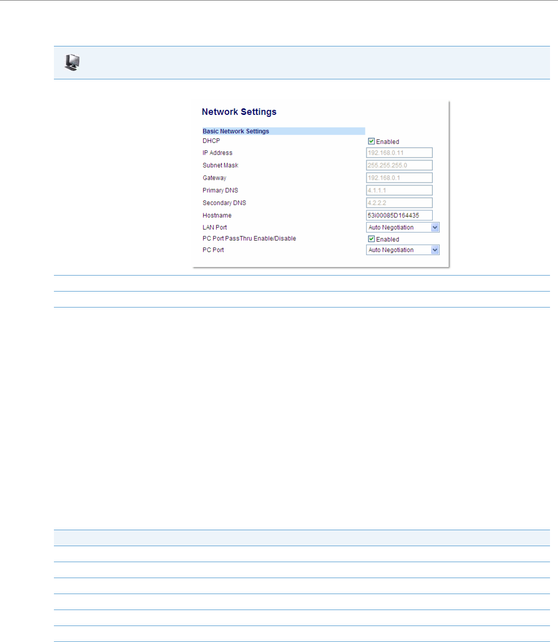
Network Settings
41-001343-02 REV04 – 05.2014 4-5
Enabling/Disabling DHCP Using the Aastra Web UI
Use the following procedure to enable/disable DHCP using the Aastra Web UI.
DHCP Options 60, 66, and 43 Server Configurations
Option 66
The IP Phones support download protocols as referenced in RFC2131 and RFC1541 (TFTP, FTP, HTTP,. HTTPS) to support
DHCP option 66. Option 66 is part of the DHCP Offer message that the DHCP server generates to tell the phone which con-
figuration server it should use to download new firmware and configuration files.
For DHCP to automatically populate the IP address or domain name for the servers, your DHCP server must support
Option 66. Option 66 is responsible for forwarding the server’s IP address or domain name to the phone automatically. If
your DHCP server does not support Option 66, you must manually enter the IP address or domain name for your applica-
ble configuration server into your IP phone configuration.
Options 60 and 43
The Aastra phones also support Option 60 and Option 43 as referenced in RFC 2132.
Option 60 (Vendor Class Identifier) provides the DHCP server with a unique identifier for each phone model. This enables
a system administrator to send the phone a customized Server Configuration in option 43.
The table below lists the identifier values for each phone model.
Aastra Web UI
1. Click on Advanced Settings->Network->Basic Network Settings.
2. Enable the "DHCP" field by checking the check box. (Disable this field by unchecking the box).
3. Click Save Settings to save your settings.
Model Identifier Value
9143i AastraIPPhone9143i
9480i AastraIPPhone9480i
9480i CT AastraIPPhone9480iCT
6730i AastraIPPhone6730i
6731i AastraIPPhone6731i
6735i AastraIPPhone6735i
6737i AastraIPPhone6737i

Network Settings
4-6 41-001343-02 REV04 – 05.2014
Option 43 consists of the following sub-options:
The System administrator can use the Vendor Class Identifier to send the phone a customized Server Configuration in
option 43 (Vendor-Specific information).
Using Option 43 to Customize the IP Phone
A System Administrator can customize the IP Phone(s) in the network by entering a text string in the phone’s configura-
tion files. The following is an Option 43 example using Linux.
On the startup of the phones, when the DHCP server receives the request with the information in this example, it allows
the 6757i phones to use FTP and the 6757i CT phones to use TFTP from the same server.
6739i AastraIPPhone6739i
6753i AastraIPPhone53i
6755i AastraIPPhone55i
6757i AastraIPPhone57i
6757i CT AastraIPPhone57iCT
6863i AastraIPPhone63i
6865i AastraIPPhone65i
6867i AastraIPPhone67i
Sub-Option/Code Description
02 Configuration server (protocol, server, and path).
03 Redirection and Configuration Server (RCS) enable/disable.
08 ID string to enable the use of the VLAN identity in sub-option/code 09. Must be specified to avoid conflict with
other vendors.
09 VLAN ID value.
Note:
If Aastra IP Phones receive the server configuration from both DHCP Option 66 and DHCP Option 43, then Option 43
takes precedence over Option 66.
Model Identifier Value

Network Settings
41-001343-02 REV04 – 05.2014 4-7
Linux Example
A System Administrator can enter the following in the DHCP server:
option space AastraIPPhone57i;
option AastraIPPhone57i.cfg-server-name code 02 = text;
option space AastraIPPhone57iCT;
option AastraIPPhone57iCT.cfg-server-name code 02 = text;
Subnet 192.168.1.0 netmask 255.255.255.0 {
class "vendor-class-57i" {
match if option vendor-class-identifier="AastraIPPhone57i";
vendor-option-space AastraIPPhone57i;
option AastraIPPhone57i.cfg-server-name "ftp://username:password@10.10.10.1";
}
class "vendor-class-57iCT" {
match if option vendor-class-identifier="AastraIPPhone57iCT";
vendor-option-space AastraIPPhone57iCT;
option AastraIPPhone57iCT.cfg-server-name "tftp://10.10.10.1";
}
}
Your DHCP server configuration file, such as the dhcpd.conf file, may include one of these lines to configure the configura-
tion server protocol and the server details.
Protocol Format Examples
HTTP http://<server>/<path> option AastraIPPhone57iCT.cfg-server-name “http://192.168.1.45”;
option AastraIPPhone57iCT.cfg-server-name “http://192.168.1.45/path”;
option AastraIPPhone57iCT.cfg-server-name “http://httpsvr.example.com/path”;
HTTPS https://<server>/<path> option AastraIPPhone57iCT.cfg-server-name “https://192.168.1.45”;
option AastraIPPhone57iCT.cfg-server-name “https://192.168.1.45/path”;
option AastraIPPhone57iCT.cfg-server-name “https://httpssvr.example.com/path”;
FTP ftp://user:password@ftpserver option AastraIPPhone57iCT.cfg-server-name “ftp://192.168.1.45”;
option AastraIPPhone57iCT.cfg-server-name “ftp://ftpsvr.example.com”;
(for anonymous user)
option AastraIPPhone57iCT.cfg-server-name “ftp://userID:password@
ftpsvr.example.com”;
TFTP tftp://tftpserver option AastraIPPhone57iCT.cfg-server-name “192.168.1.45”;
option AastraIPPhone57iCT.cfg-server-name “tftpsvr.example.com”;
option AastraIPPhone57iCT.cfg-server-name “tftp://tftpsvr.example.com”;

Network Settings
4-8 41-001343-02 REV04 – 05.2014
Option 43 Redirection and Configuration Server (RCS) Bypass
DHCP Option 43 includes the ability to bypass contacting Aastra's Redirection and Configuration Server (RCS), in addi-
tion to the previous support of setting the configuration server to contact.
A sub-option code 3 uses a boolean value (true or false) that controls whether or not the phone should contact the RCS
after a factory default. If this value is set to false, the RCS is not contacted. If it is set to true or is missing, then the RCS is
contacted as per previous releases. This can be used in conjunction with the existing code 2 sub-option to set the con-
figuration server.
Configuring RCS Bypass via Option 43 on a Linux DHCP Server
The following example illustrates how to configure RCS bypass via Option 43 on a Linux DHCP server.
option space AastraIPPhone;
option AastraIPPhone.cfg-server-name code 02 = text;
option AastraIPPhone.contact-rcs code 03 = boolean;
Subnet 192.168.1.0 netmask 255.255.255.0 {
#The 6757i phones do not contact the RCS but use the defined FTP server for configuration
#files.
class "vendor-class-57i" {
match if option vendor-class-identifier="AastraIPPhone57i";
vendor-option-space AastraIPPhone;
option AastraIPPhone.cfg-server-name "ftp://username:password@10.10.10.1";
option AastraIPPhone.contact-rcs false;
}
#The 6757iCT phones do not contact the RCS.
class "vendor-class-57iCT" {
match if option vendor-class-identifier="AastraIPPhone57iCT";
vendor-option-space AastraIPPhone;
option AastraIPPhone.contact-rcs false;
Using Option 120 on the IP Phone
DHCP Option 120 (as referenced in RFC 3361) allows SIP clients to locate a local SIP server (i.e. outbound proxy server)
that can be used for all outbound SIP requests. Using the “use dhcp option 120” configuration parameter, administra-
tors can enable support for DHCP Option 120 on the IP phones. This is particularly useful when service providers require
the IP phones to use certain outbound proxy servers or Session Border Controllers (SBCs) based on geographical loca-
tion and have provisioned the outbound proxy by using DHCP Option 120. The parameter is disabled by default.
Considerations
The following considerations must be taken into account when enabling support for DHCP Option 120 on the IP phones:
•If the parameter is enabled and DHCP Option 120 contains a valid value, the IP phones will use the server IP/name
obtained via DHCP Option 120 as the outbound proxy for both the Global SIP and Line 1 profiles.
•If Line 2 is configured and the outbound proxy is not defined, the phone will use the outbound proxy located in the
Global SIP profile.

Network Settings
41-001343-02 REV04 – 05.2014 4-9
•If Line 2 is configured with a valid outbound proxy, the phone will retain the configured Line 2 outbound proxy and
ignore the Global SIP profile. This allows for Line 2 to be registered to another service with another outbound proxy if
required.
•If Line 2 is configured for another service but no outbound proxy is wanted/required, administrators should not leave
the outbound proxy as undefined (i.e. 0.0.0.0) as the phone will use the outbound proxy located in the Global SIP pro-
file. Instead, administrators should specify the proxy/registrar’s address as the outbound proxy.
•If the parameter is enabled, but the server does not have an outbound proxy configured, DHCP Option 120 is ignored
and the phone will behave as if the parameter is disabled.
•As Option 120 does not support port numbers directly, if a non-standard port (i.e. other than 5060) is required, this
must be set using the configuration parameter “sip outbound proxy port” or by the use of DNS SRV in which case “sip
outbound proxy port” must be set to 0.
Enabling/Disabling DHCP Option 120 Using the Configuration Files
Use the following procedure to enable/disable DHCP Option 120 using the configuration files.
Using Option 132 (802.1P VLAN ID) and Option 43 to Transfer VLAN ID Assignment Using DHCP
There are now two ways of transporting the VLAN ID parameter in the Dynamic Host Configuration Protocol (DHCP):
•By DHCP Option 43 (vendor specific information)
•By DHCP Option 132 (802.1P VLAN ID)
When the phone receives the VLAN ID from the DHCP and the value is different from the one used by the phone to trigger
the DHCP request, the phone reboots and then sends a new DHCP request in the new VLAN. The phone will remember the
VLAN ID obtained by DHCP options so that on a reboot, the phone will send a DHCP request using the correct VLAN.
If using DHCP Option 43 to transfer VLAN ID assignment the following sub-options are utilized. Additionally, the corre-
sponding rules must be followed:
Alternatively, administrators can use the “dhcp option 132 vlan id enabled” parameter to enable the VLAN ID assign-
ment transfer using DHCP feature. Option 132 provides the same functionality as Option 43 but the data format of the
VLAN ID value must be 2 bytes, whereas the first and second bytes encompass the VLAN ID (the valid range of the VLAN ID
being 1 - 4095).
Precedence
•LLDP values should have precedence over the DHCP
•DHCP values should have precedence over the configuration files
•DHCP should have precedence over the Local values (configured by the Local MMI of the phone)
•DHCP Option 43 should have precedence over DHCP Option 132
Configuration Files
For specific parameters you can set in the configuration files, see Appendix A, the section, “DHCP Option Settings” on pageA-12.
Sub-
Option/Code Description Rule
08 ID string to enable the use of the VLAN identity in
sub-option/code 09. Must be specified to avoid
conflict with other vendors.
Must be the 16-byte character string “Aastra{space}Telecom{space}{space}”
(i.e. Aastra Telecom followed by two space characters).
16-byte hex equivalent: 4161737472612054656c65636f6d2020
09 VLAN ID value Must be 4 bytes, whereas the first and second byte must be 0x00, and the third
and fourth bytes encompass the VLAN ID. The valid range of the VLAN ID is 1 -
4095.
For example, a VLAN ID of 100 (in dec) is 00 00 00 64 in hex.

Network Settings
4-10 41-001343-02 REV04 – 05.2014
Configuring Option 43 to Transfer VLAN ID Assignment on a Linux DHCP Server
The following example (covering all the phones) illustrates how to configure Option 43 to transfer VLAN ID assignment
on a Linux DHCP server.
option space AastraIPPhone;
option AastraIPPhone.cfg-server-name code 02 = text;
option AastraIPPhone.contact-rcs code 03 = boolean;
option AastraIPPhone.ActivateVLANHeader code 08 = text;
option AastraIPPhone.VLAN-ID code 09 = unsigned integer 32;
class "AastraSIP" {
match if ( (option vendor-class-identifier="AastraIPPhone6730i")
or (option vendor-class-identifier="AastraIPPhone9143i")
or (option vendor-class-identifier="AastraIPPhone9480i")
or (option vendor-class-identifier="AastraIPPhone9480iCT")
or (option vendor-class-identifier="AastraIPPhone6730i")
or (option vendor-class-identifier="AastraIPPhone6731i")
or (option vendor-class-identifier="AastraIPPhone6735i")
or (option vendor-class-identifier="AastraIPPhone6737i")
or (option vendor-class-identifier="AastraIPPhone6739i")
or (option vendor-class-identifier="AastraIPPhone53i")
or (option vendor-class-identifier="AastraIPPhone55i")
or (option vendor-class-identifier="AastraIPPhone57i")
or (option vendor-class-identifier="AastraIPPhone57iCT") );
vendor-option-space AastraIPPhone;
option AastraIPPhone.cfg-server-name "http://192.168.174.200/aastra"; # option 43
option AastraIPPhone.contact-rcs false; # option 43
option AastraIPPhone.ActivateVLANHeader "Aastra Telecom "; # option 43
option AastraIPPhone.VLAN-ID 100; # option 43
} # endClass
Enabling/Disabling DHCP Option 132 VLAN ID Using the Configuration Files
Use the following procedure to enable/disable DHCP Option 132 VLAN ID using the configuration files.
Using Option 12 Hostname on the IP Phone
If you set the phone to use DHCP Option 12, the phone automatically sends this option to the configuration server. This
option specifies the hostname (name of the client). The name may or may not be qualified with the local domain name
(based on RFC 2132). See RFC 1035 for character set restrictions.
An Administrator can change the “Hostname” for the DHCP Option 12 via the configuration files, the IP Phone UI, and the
Aastra Web UI.
Configuration Files
For specific parameters you can set in the configuration files, see Appendix A, the section, “DHCP Option Settings” on pageA-12.
Notes:
•The hostname of [<model><MAC address>] automatically populates the field on initial startup of the phone. For
example, for a 6753i, the “Hostname” field is automatically populated as “53i00085D164435”, where the model
number is “6753i” and the MAC address is “00085D164435”.
•If the configuration server sends the hostname back to the phone in a DHCP Reply Packet, the hostname is ignored.
Network Settings
41-001343-02 REV04 – 05.2014 4-11
Configuring DHCP Option 12 Hostname on the IP Phone
Use the following procedures to configure DHCP Option 12 Hostname on the IP Phone.
Configuration Files
For specific parameters you can set in the configuration files, see Appendix A, the section, “DHCP Option Settings” on pageA-12.
IP Phone UI
1. Press Options, and then select Administrator Menu.
2. Select Network Settings.
3. Select Hostname.
4. By default, the “Hostname” field is automatically populated with [<Model><MAC address>] of your phone (for example,
53i00085D164435).
If you want to change the hostname, enter a hostname for your phone in the “Hostname” field, then press DONE.
Valid values are up to 64 alpha-numeric characters. You can use a fully qualified domain name if required.
5. Restart the phone for the change to take affect.
For the 6739i:
1. Press the Options key on the phone to enter the Options List.
2. Press Advanced. A keyboard displays.
3. Enter the Administrator password using the keyboard. Default is “22222”.
4. Press Network.
5. Press to scroll to the next screen.
6. By default, the “Hostname” field is automatically populated with [<Model><MAC address>] of your phone (for example,
53i00085D164435).
If you want to change the hostname, press the button in the “Hostname” field, and enter a hostname for your phone in the text box that
displays.
Valid values are up to 64 alpha-numeric characters. You can use a fully qualified domain name if required.
7. Press until the Options List screen displays.
8. Press Restart to restart the phone for the change to take affect.
For the 6867i:
1. Press on the phone to enter the Options List.
2. Press the Advanced softkey.
3. Enter the Administrator password using the keypad. Default is “22222”.
4. Select Network > Settings.
5. Press the down navigation key to the Hostname field.
6. By default, the “Hostname” field is automatically populated with [<Model><MAC address>] of your phone (for example,
53i00085D164435).
If you want to change the hostname, enter a hostname for your phone in the “Hostname” field, then press the Save softkey.
Valid values are up to 64 alpha-numeric characters. You can use a fully qualified domain name if required.
7. Restart the phone for the change to take affect.
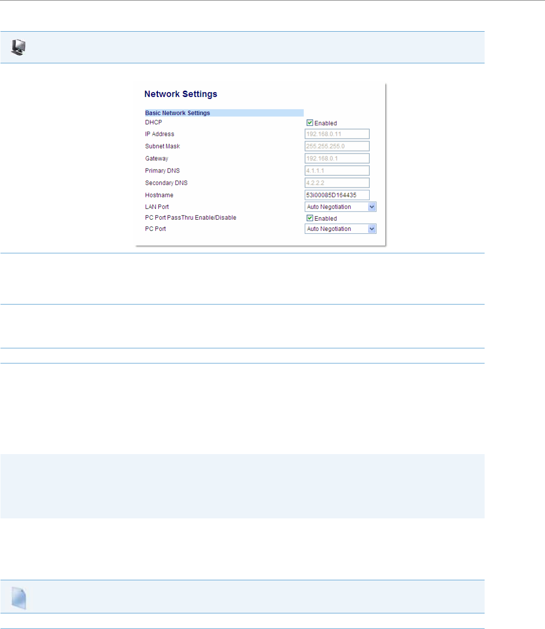
Network Settings
4-12 41-001343-02 REV04 – 05.2014
Using Option 77 User Class on the IP Phone
DHCP Option 77 User Class is sent in DHCP request packets from the phone to the configuration server. This Option 77
defines specific User Class identifiers to convey information about a phone’s software configuration or about its user's
preferences. For example, you can use the User Class option to configure all phones in the Accounting Department with
different user preferences than the phones in the Marketing Department. A DHCP server uses the User Class option to
choose the address pool for which it allocates an address from, and/or to select any other configuration option.
An Administrator can configure the DHCP Option 77 User Class via the configuration files and the IP Phone UI.
Configuring DHCP Option 77 User Class on the IP Phone
Use the following procedures to configure DHCP Option 77 User Class on the IP Phone.
Aastra Web UI
1. Click on Advanced Settings->Network->Basic Network Settings.
2. By default, the “Hostname” field is automatically populated with [<Model><MAC address>] of your phone (for example,
53i00085D164435).
If you want to change the hostname, enter a hostname for your phone in the “Hostname” field.
Valid values are up to 64 alpha-numeric characters. You can use a fully qualified domain name if required.
3. Click Save Settings to save your changes.
Note:
Changing the “Hostname” field requires a reboot of your phone.
4. Click on Operation->Reset, and click Restart.
Notes:
•If the User Class is not specified (left blank) in the DHCP request packet, the phone does not send the User Class DHCP
Option 77.
•Multiple User Classes inside a DHCP Option 77 are not supported.
•DHCP Option 77 may affect the precedence of DHCP Options, dependent on the DHCP Server.
Configuration Files
For specific parameters you can set in the configuration files, see Appendix A, the section, “DHCP Option Settings” on pageA-12.

Network Settings
41-001343-02 REV04 – 05.2014 4-13
Using Options 159 and 160 on the IP Phone
In addition to DHCP options 43 and 66 already supported on the IP Phones, the phones also support DHCP Options 159
and 160. The IP Phones use the following order of precedence when deriving the configuration server parameters: 43, 160,
159, 66.
In addition, an administrator can override this order of precedence by setting a configuration parameter called, dhcp con-
fig option override (configuration files), DHCP Download Options (Aastra Web UI), or Download Options (IP Phone UI).
Setting this parameter results in the phone only using the chosen DHCP option and ignoring the other options.
For more information about setting DHCP download preference, see “Configuration Server Download Precedence” on
page4-15.
Configuring DHCP Download Options on the IP Phones
Use the following procedures to configure DHCP Option Override on the IP Phone.
IP Phone UI
1. Press Options, and then select Administrator Menu.
2. Select Network Settings.
3. Select DHCP Settings.
4. Select DHCP User Class.
5. In the “DHCP User Class” field, enter a DHCP User Class to apply to your phones, then press DONE.
Valid values are up to 64 alpha-numeric characters. For example, “admin”.
6. Restart the phone for the change to take affect.
For the 6867i:
1. Press on the phone to enter the Options List.
2. Press the Advanced softkey.
3. Enter the Administrator password using the keypad. Default is “22222”.
4. Select Network > Settings.
5. Press the down navigation key to the DHCP User Class field.
6. In the “DHCP User Class” field, enter a DHCP User Class to apply to your phones, then press the Save softkey.
Valid values are up to 64 alpha-numeric characters. For example, “admin”.
7. Restart the phone for the change to take affect.
Note:
Administrators should review the updated IP phone DHCP option precedence order and configuration options to
avoid potential impact to existing Aastra IP phone deployments.
Configuration Files
For specific parameters you can set in the configuration files, see Appendix A, the section, “DHCP Option Settings” on pageA-12.
IP Phone UI
1. Press Options, and then select Administrator Menu.
2. Enter you Administrator password and press Enter.
Network Settings
4-14 41-001343-02 REV04 – 05.2014
3. Select Network Settings.
4. Select DHCP Settings.
5. Select Download Options. The following list displays:
•Any (default) - no override - uses normal precedence order of 43, 160, 159, 66.
•Option 43
•Option 66
•Option 159
•Option 160
•Disabled (Ignores all DHCP configuration options (43, 66, 159, 160))
6. Choose an option that you want to use to override the DHCP normal precedence order, and press Done.
7. Restart the phone for the selection to take affect.
For the 6739i:
1. Press the Options key on the phone to enter the Options List.
2. Press Advanced. A keyboard displays.
3. Enter the Administrator password using the keyboard. Default is “22222”.
4. Press Network.
5. Press DHCP Settings.
6. Press DHCP Download Options.
7. Select and press the “Option 159” or “Option 160” value.
8. Press until the Options List screen displays.
9. Press Restart to restart the phone for the change to take affect.
For the 6867i:
1. Press on the phone to enter the Options List.
2. Press the Advanced softkey.
3. Enter the Administrator password using the keypad. Default is “22222”.
4. Select Network > Settings.
5. Press the down navigation key to the DHCP Download Options field.
6. Select one of the following DHCP download options using the left and right navigation keys.
•Any (default) - no override - uses normal precedence order of 43, 160, 159, 66.
•Option 43
•Option 66
•Option 159
•Option 160
•Disabled (Ignores all DHCP configuration options (43, 66, 159, 160))
7. Press the Save softkey.
8. Restart the phone for the selection to take affect.
IP Phone UI
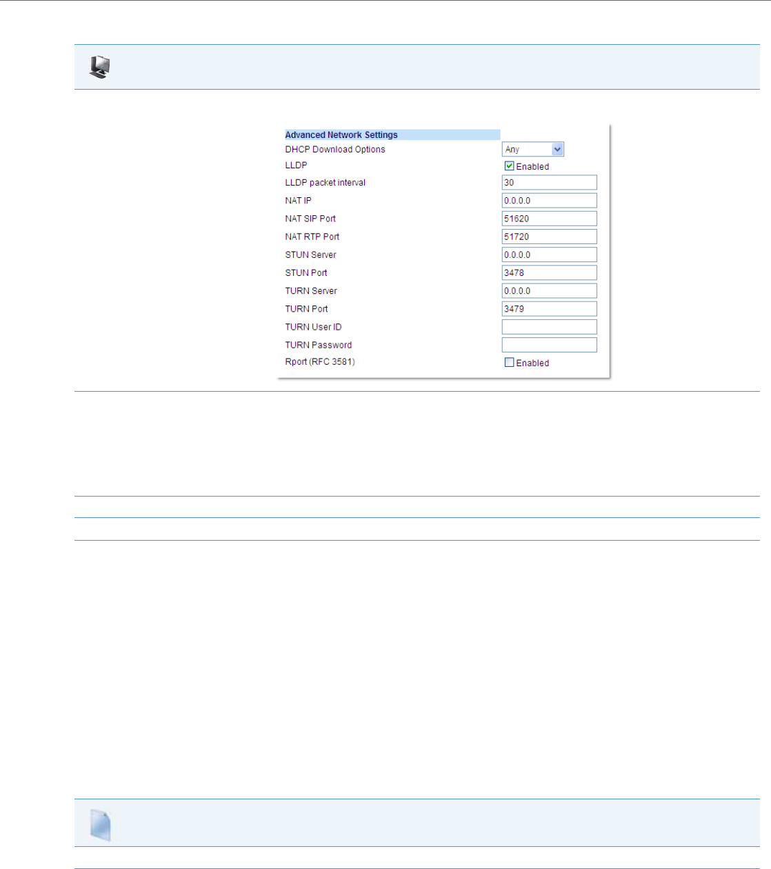
Network Settings
41-001343-02 REV04 – 05.2014 4-15
Configuration Server Download Precedence
An Administrator can set the phone’s download precedence to ignore DHCP, (only during the boot when the remote
configuration server is contacted) and use the following precedence instead:
To configure the download precedence, you use the option value (-1) as the value for the “dhcp config option override”
parameter in the configuration files. Setting this parameter to “-1” causes all DHCP configuration options to be ignored.
Configuring a Download Precedence Using the Configuration Files
Use the following procedure to configure the DHCP download precedence using the configuration files.
Aastra Web UI
1. Click on Advanced Settings->Network->Advanced Network Settings.
2. In the “DHCP Download Options” field, select an option to use to override the normal precedence order. Valid values are:
•Any (default) - no override - uses normal precedence order of 43, 160, 159, 66.
•Option 43
•Option 66
•Option 159
•Option 160
•Disabled (Ignores all DHCP configuration options (43, 66, 159, 160))
3. Click Save Settings to save your changes.
4. Click on Operation->Reset, and restart the phone for the changes to take affect.
1. Configuration URI,
2. DHCP, and then
3. Direct configuration.
Configuration Files
For specific parameters you can set in the configuration files, see Appendix A, the section, “DHCP Option Settings” on pageA-12.
Network Settings
4-16 41-001343-02 REV04 – 05.2014
Configuring a Download Precedence Using the IP Phone UI
Use the following procedure to configure a download precedence using the IP Phone UI.
IP Phone UI
1. Press Options, and then select Administrator Menu.
2. Enter you Administrator password and press Enter.
3. Select Network Settings.
4. Select DHCP Settings.
5. Select Download Options.
Note:
Disabled (Ignores all DHCP configuration options (43, 66, 159, 160))
6. Select the Disabled option and press Enter.
Note:
The “Disabled” download option performs the same function as the “-1” in the configuration files (ignores DHCP options).
7. Restart the phone for the selection to take affect.
For the 6739i:
1. Press the Options key on the phone to enter the Options List.
2. Press Advanced. A keyboard displays.
3. Enter the Administrator password using the keyboard. Default is “22222”.
4. Press Network.
5. Press DHCP Settings.
6. Press DHCP Download Options.
7. Select and press the “Disabled” value.
Note:
Disabled (Ignores all DHCP configuration options (43, 66, 159, 160). This option also performs the same function as the “-1” in the config-
uration files (ignores DHCP options).
8. Press until the Options List screen displays.
9. Press Restart to restart the phone for the change to take affect.
For the 6867i:
1. Press on the phone to enter the Options List.
2. Press the Advanced softkey.
3. Enter the Administrator password using the keypad. Default is “22222”.
4. Select Network > Settings.
5. Press the down navigation key to the DHCP Download Options field.
6. Select the “Disabled” value.
Note:
Disabled (Ignores all DHCP configuration options (43, 66, 159, 160). This option also performs the same function as the “-1” in the config-
uration files (ignores DHCP options).
7. Press the Save softkey.
8. Restart the phone for the selection to take affect.
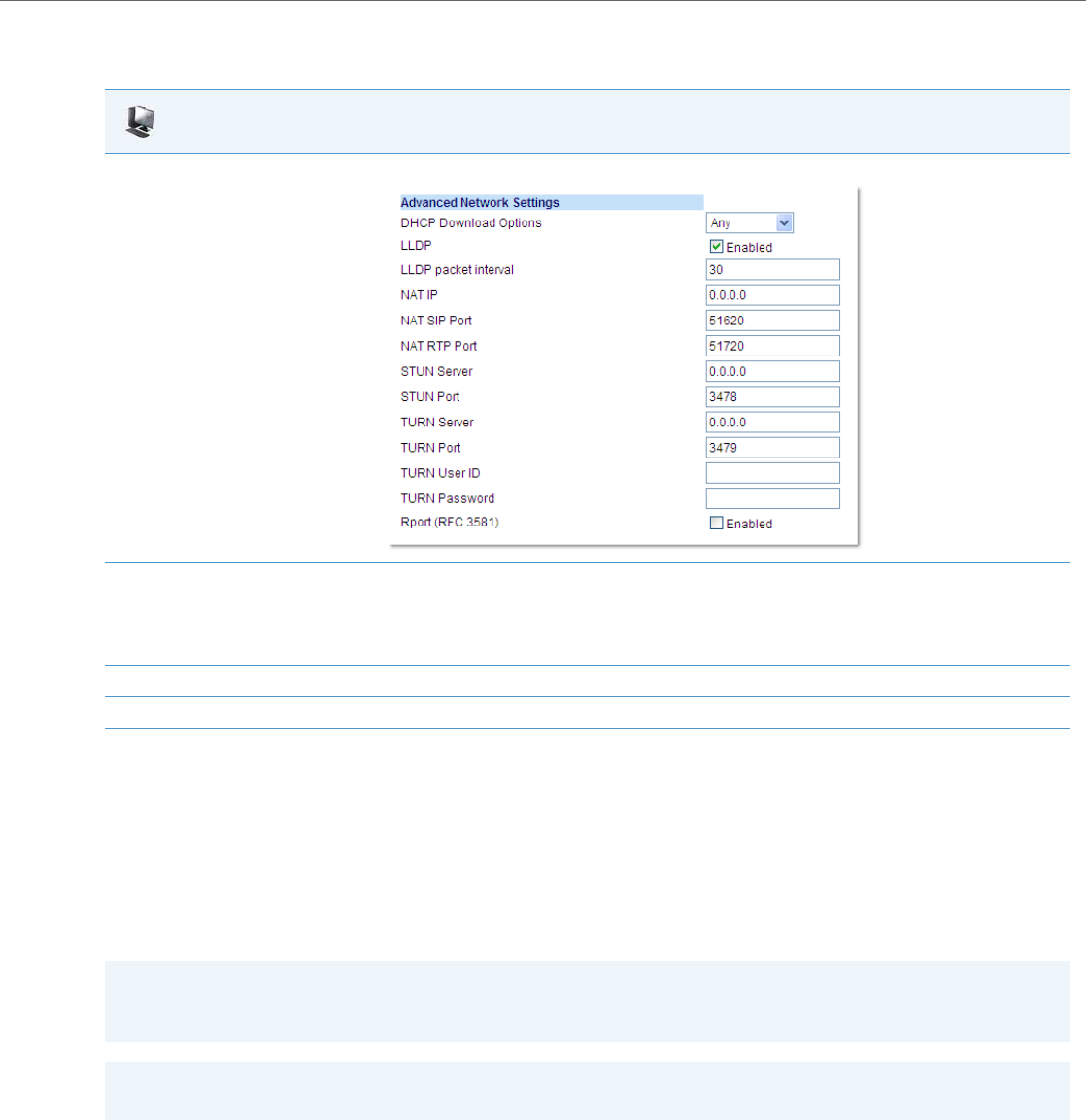
Network Settings
41-001343-02 REV04 – 05.2014 4-17
Configuring a Download Precedence Using the Aastra Web UI
Use the following procedure to configure a download precedence using the Aastra Web UI.
Multiple DHCP Servers
The IP Phones can receive messages from multiple DHCP servers.
After the phone receives its first DHCP message, it listens for a specific time period, for more DHCP messages. If the first
DHCP offer contains configuration server information (Options 43, 66, 159 or 160), then the phone times out and contin-
ues using the first DHCP offer, without listening for more DHCP offers. If the first DHCP message contains no configuration
server information, the phone continues to listen for other DHCP messages. If the second DHCP message contains config-
uration server information and other conditions, the phone chooses the second DHCP message over the initial DHCP mes-
sage.
DNS Caching
The IP phones have the ability to cache DNS requests as referenced in RFC1035 and RFC2181. The phone caches DNS
lookups according to the TTL field, so that the phone only performs another lookup for an address when the TTL expires.
Aastra Web UI
1. Click on Advanced Settings->Network->Advanced Network Settings.
2. In the “DHCP Download Options” field, select “Disabled” from the list of options.
Note:
In the Aastra Web UI, the “Disabled” download option performs the same function as the “-1” in the configuration files (ignores DHCP
options).
3. Click Save Settings to save your setting.
4. Select Operation->Reset, and click Restart to reboot the phone.
Note:
If the DHCP Download Options parameter is enabled with a value (Option 43, Option 66, Option 159, or Option 160),
the phone checks the override option setting before timing out.
Warning!
Users currently using multiple DHCP servers on a single network could be affected by this feature.
Network Settings
4-18 41-001343-02 REV04 – 05.2014
Configuring Network Settings Manually
If you disable DHCP on your phone, you need to configure the following network settings manually:
•IP Address
•Subnet Mask
•Gateway
•Primary DNS
•Secondary DNS
You can configure the network settings using the configuration files, the IP phone UI, or the Aastra Web UI.
Errors Messages Display when Incorrect Network Settings Entered
The IP Phone UI AND the Aastra Web UI immediately notify the Administrator if an incorrect value is being entered for
the following network parameters in the IP Phone UI and the Aastra Web UI:
•A 0.0.0.0 entered as values for the IP Address, Subnet Mask and Gateway parameters
•IP Address and Gateway IP address parameter values entered exactly the same
•Gateway IP address and the IP address parameter values configured on the same subnet
If you configure the Gateway parameter and the IP Address parameter on the same subnet, the following error message
displays:
“Gateway IP address and the IP address parameter values configured are not on the same subnet”.
Note:
If you disable DHCP on the phone, the phone uses the TFTP protocol as the default server protocol. If you want to spec-
ify a different protocol to use, see “Configuration Server Protocol” on page4-87.
Configuration Files
For specific parameters you can set in the configuration files, see Appendix A, the section, “Network Settings” on pageA-8.
IP Phone UI
1. Press on the phone to enter the Options List.
2. Select Administrator Menu.
3. Enter your Administrator password.
Note:
The IP Phones accept numeric passwords only.
4. Select Network Settings.
5. Select IP Address and enter the IP address of the phone.
6. Select Subnet Mask and enter the subnet mask.
7. Select Gateway and enter the gateway address.
8. Select DNS and enter a Primary and/or Secondary DNS server.
9. Press Done to save the changes.
The IP phone is manually configured.
Network Settings
41-001343-02 REV04 – 05.2014 4-19
For the 6739i:
Note:
To manually configure DHCP parameters, DHCP must be disabled on the phone.
1. Press the Options key on the phone to enter the Options List.
2. Press Advanced. A keyboard displays.
3. Enter the Administrator password using the keyboard. Default is “22222”.
4. Press Network.
5. Press IP Address, enter the IP address of your phone in the text box and press . The IP Address must be entered in the format
0.0.0.0; for example, 192.168.0.7.
6. Press the Subnet Mask button, enter the subnet mask address and press . For example, 255.255.0.0.
7. Press Gateway, enter the IP address of your gateway in the text box and press . The Gateway must be entered in the format
0.0.0.0; for example, 192.168.0.1.
8. If required, press the Primary DNS and/or Secondary DNS buttons, enter the IP address of these servers as applicable and press .
The IP addresses must be entered in the format 0.0.0.0.
The IP Phone is manually configured.
For the 6867i:
Note:
To manually configure DHCP parameters, DHCP must be disabled on the phone.
1. Press on the phone to enter the Options List.
2. Press the Advanced softkey.
3. Enter the Administrator password using the keypad. Default is “22222”.
4. Select Network > Settings.
5. In the IP Address field, enter the IP address of your phone. The IP Address must be entered in the format 0.0.0.0; for example, 192.168.0.7.
6. In the Subnet Mask field, enter the subnet mask address. For example, 255.255.0.0.
7. In the Gateway field, enter the IP address of your gateway. The Gateway must be entered in the format 0.0.0.0; for example, 192.168.0.1.
8. If required, enter the Primary DNS and/or Secondary DNS in the respective fields. The IP addresses must be entered in the format 0.0.0.0.
9. Press the Save softkey.
The IP Phone is manually configured.
IP Phone UI
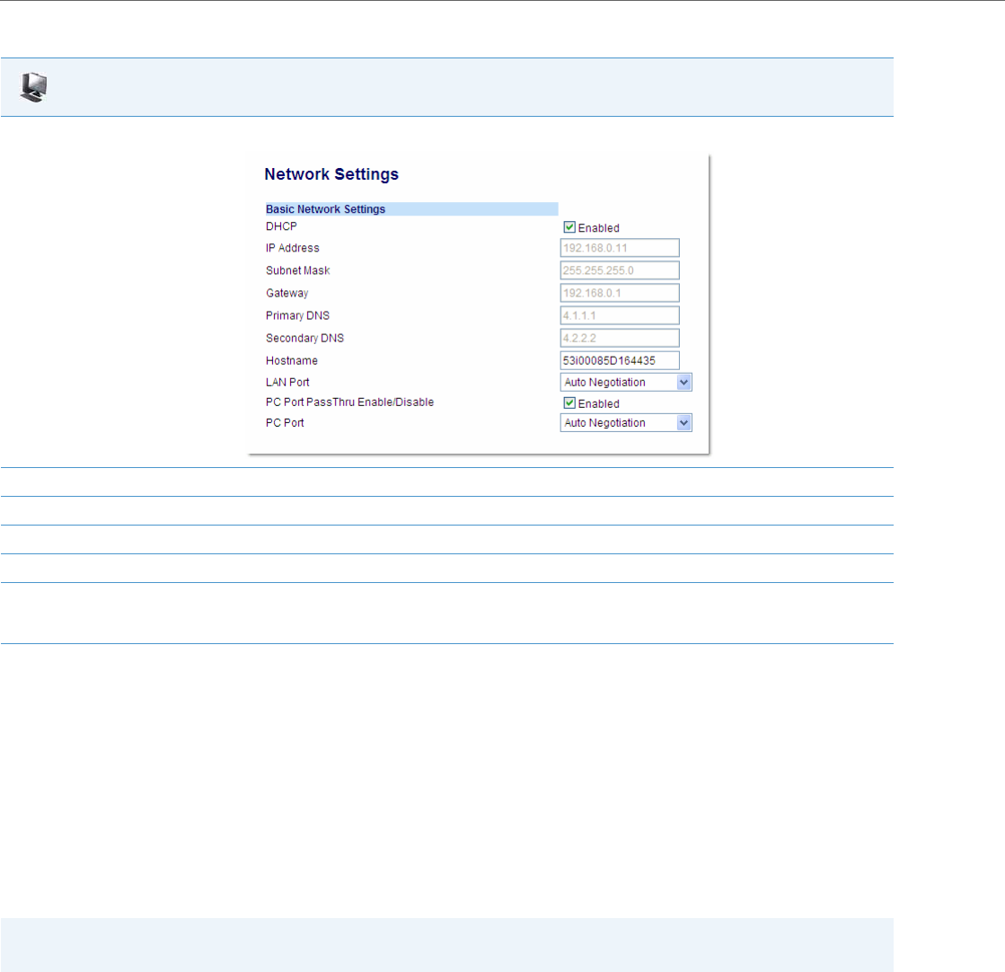
Network Settings
4-20 41-001343-02 REV04 – 05.2014
Configuring LAN and PC Port Negotiation
Ethernet is the computer networking technology for local area networks (LANs). You use the LAN Port to connect to a
LAN using a twisted pair 10BASE-T cable to transmit 10BASE-T Ethernet. You use the PC Port to connect to the configura-
tion server (your PC).
There are two Ethernet ports on the rear of the IP phones: LAN Port and PC Port. Using the Aastra Web UI, you can select
the type of transmission you want these ports to use to communicate over the LAN. The IP phones support each of the
following methods of transmission:
•Auto-negotiation
•Half-duplex (10Mbps, 100 Mbps, or 1000Mbps [if applicable])
•Full-duplex (10Mbps, 100 Mbps, or 1000Mbps [if applicable])
Auto-negotiation
Auto-negotiation is when two connected devices choose common transmission parameters. In the auto-negotiation
process, the connected devices share their speed and duplex capabilities and connect at the highest common denomi-
nator (HCD). Auto-negotiation can be used by devices that are capable of different transmission rates (such as
10Mbit/sec and 100Mbit/sec [and 1000Mbit/sec for the 6739i, 6735i, 6737i, 6865i, and 6867i]), different duplex modes
(half duplex and full duplex) and/or different standards at the same speed. You can set the LAN and PC Ports on the IP
phones to auto-negotiate during transmission.
Aastra Web UI
1. Click on Advanced Settings->Network->Basic Network Settings.
2. Enter an IP address of the phone in the IP Address field.
3. Enter a subnet mask in the Subnet Mask field.
4. Enter a gateway address in the Gateway field.
5. Enter a Primary DNS in the Primary DNS field, and/or a secondary DNS in the Secondary DNS field.
6. Click Save Settings to save your settings.
The IP phone is manually configured.
Note:
The PC Port parameters are not applicable to the 6730i IP Phone.
Network Settings
41-001343-02 REV04 – 05.2014 4-21
Half-Duplex (10Mbps , 100Mbps, or 1000Mbps)
Half-duplex data transmission means that data can be transmitted in both directions on a signal carrier, but not at the
same time. For example, on a LAN using a technology that has half-duplex transmission, one device can send data on the
line and then immediately receive data on the line from the same direction in which data was just transmitted. Half-duplex
transmission implies a bidirectional line (one that can carry data in both directions). On the IP phones, you can set the half-
duplex transmission to transmit in 10Mbps or in 100Mbps. Additionally, for the 6739i, 6735i, 6737i, 6865i, and 6867i IP
phones, you can set the half-duplex transmission to transmit in 1000Mbps.
Full-Duplex (10Mbps , 100Mbps or 1000Mbps)
Full-duplex data transmission means that data can be transmitted in both directions on a signal carrier at the same time.
For example, on a LAN with a technology that has full-duplex transmission, one device can be sending data on the line
while another device is receiving data. Full-duplex transmission implies a bidirectional line (one that can move data in
both directions). On the IP phones, you can set the full-duplex transmission to transmit in 10Mbps or in 100Mbps. Addi-
tionally, for the 6739i, 6735i, 6737i, 6865i, and 6867i IP phones, you can set the full-duplex transmission to transmit in
1000Mbps.
Configuring the LAN Port and PC Port
You can configure the Ethernet port transmission method to use on the IP phones using the configuration files, the IP
Phone UI, or the Aastra Web UI.
Configuration Files
For specific parameters you can set in the configuration files, see Appendix A, the section, “Network Settings” on pageA-8.
IP Phone UI
1. Press on the phone to enter the Options List.
2. Select Administrator Menu.
3. Enter your Administrator password.
Note:
The IP Phones accept numeric passwords only.
4. Select Network Settings.
5. Select Ethernet.
6. Select LAN Port Link.
7. Select a negotiation method to use on port 0 and press Done. Valid values are:
•AutoNegotiation
•Full 10Mbps
•Full 100Mbps
•Full 1000Mbps (applicable for the 6739i, 6735i, 6737, 6865i, and 6867i IP phones only)
•Half 10Mbps
•Half 100Mbps
•Half 1000Mbps (applicable for the 6739i, 6735i, 6737, 6865i, and 6867i IP phones only)
Default is AutoNegotiation.
8. Select PC Port Link.
Note:
PC Port Link parameters are not applicable to the 6730i IP Phone.
Network Settings
4-22 41-001343-02 REV04 – 05.2014
9. Select a negotiation method to use on port 1and press Done. Valid values are:
•AutoNegotiation
•Full 10Mbps
•Full 100Mbps
•Full 1000Mbps (applicable for the 6739i, 6735i, 6737, 6865i, and 6867i IP phones only)
•Half 10Mbps
•Half 100Mbps
•Half 1000Mbps (applicable for the 6739i, 6735i, 6737, 6865i, and 6867i IP phones only)
Default is AutoNegotiation.
10. Press Done (3 times) to finish configuring the configuration server protocol for the IP phone.
Note:
The session prompts you to restart the IP phone to apply the configuration settings.
11. Select Restart.
For the 6739i:
1. Press the Options key on the phone to enter the Options List.
2. Press Advanced. A keyboard displays.
3. Enter the Administrator password using the keyboard. Default is “22222”.
4. Press Network.
5. Press to scroll to the next screen.
6. Press Ethernet & VLAN.
7. Press LAN Port.
8. Select a negotiation method to use on port 0. Valid values are:
•Auto
•Full 10Mbps
•Full 100Mbps
•Full 1000Mbps
•Half 10Mbps
•Half 100Mbps
•Half 1000Mbps
Default is Auto.
9. Press
10. Press PC Port.
11. Select a negotiation method to use on port 1. Valid values are:
•Auto
•Full 10Mbps
•Full 100Mbps
•Full 1000Mbps
•Half 10Mbps
•Half 100Mbps
•Half 1000Mbps
Default is Auto.
12. Press until the Options List screen displays.
13. Press Restart to restart the phone for the change to take affect.
IP Phone UI

Network Settings
41-001343-02 REV04 – 05.2014 4-23
For the 6867i:
1. Press on the phone to enter the Options List.
2. Press the Advanced softkey.
3. Enter the Administrator password using the keypad. Default is “22222”.
4. Select Network > Ethernet Ports.
5. With LAN Port highlighted, press the right navigation key and select a negotiation method to use on port 0. Valid values are:
•AutoNegotiation
•Full 10Mbps
•Full 100Mbps
•Full 1000Mbps
•Half 10Mbps
•Half 100Mbps
•Half 1000Mbps
Default is AutoNegotiation.
6. Press the left navigation key and press down to highlight PC Port.
7. Select a negotiation method to use on port 1. Valid values are:
•AutoNegotiation
•Full 10Mbps
•Full 100Mbps
•Full 1000Mbps
•Half 10Mbps
•Half 100Mbps
•Half 1000Mbps
Default is AutoNegotiation.
8. Press the Save softkey.
9. Restart the phone for the selection to take affect.
IP Phone UI
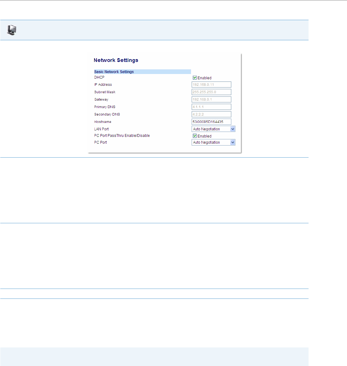
Network Settings
4-24 41-001343-02 REV04 – 05.2014
Advanced Network Settings
You can set advanced network settings on the IP phone such as, Network Address Translation (NAT), Network Time Pro-
tocol (NTP) Time Servers, Virtual LAN (VLAN), and Quality of Service (QoS) using the Aastra Web UI or the configuration
files.
Network Address Translation (NAT)
The protocols used by all IP phones do not interoperate completely with Network Address Translation (NAT). For the IP
Phones, specific configuration parameters allow the phone to operate while connected to a network device that
enforces NAT. The following is a sample network using a NAT proxy and relevant IP phone configuration parameters.
Aastra Web UI
1. Click on Advanced Settings->Network->Basic Network Settings.
2. In the “LAN Port” field, select a negotiation method to use on port 0. Valid values are:
•Auto Negotiation
•Full Duplex, 10Mbps
•Full Duplex, 100Mbps
•Full Duplex, 1000Mbps (applicable for the 6739i, 6735i, 6737, 6865i, and 6867i IP phones only)
•Half Duplex, 10Mbps
•Half Duplex, 100Mbps
•Half Duplex, 1000Mbps (applicable for the 6739i, 6735i, 6737, 6865i, and 6867i IP phones only)
Default is Auto Negotiation.
3. In the “PC Port” field, select a negotiation method to use on port 1. Valid values are:
•Auto Negotiation
•Full Duplex, 10Mbps
•Full Duplex, 100Mbps
•Full Duplex, 1000Mbps (applicable for the 6739i, 6735i, 6737, 6865i, and 6867i IP phones only)
•Half Duplex, 10Mbps
•Half Duplex, 100Mbps
•Half Duplex, 1000Mbps (applicable for the 6739i, 6735i, 6737, 6865i, and 6867i IP phones only)
Default is Auto Negotiation.
4. Click Save Settings to save your settings.
Note:
The available advanced network parameters via the IP phone UI are NAT, VLAN, and QoS only.
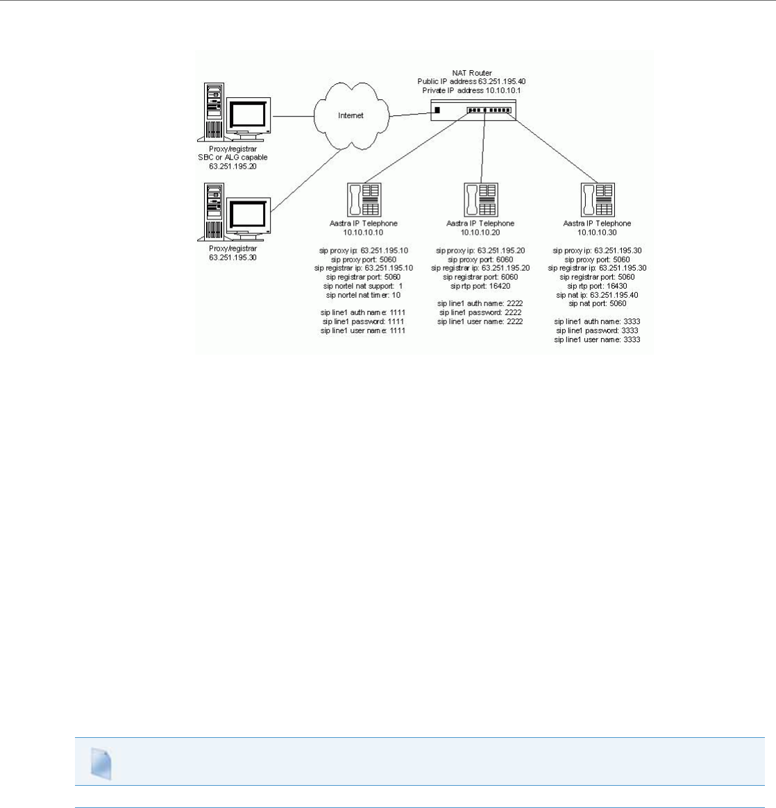
Network Settings
41-001343-02 REV04 – 05.2014 4-25
SBC or ALG Proxy/Registrar
The phone at IP address 10.10.10.20 is configured to register with the proxy at 63.251.195.20. Because the proxy/registrar
has session border control (SBC) or application layer gateway (ALG) functionality, no additional IP phone configuration is
required.
Other Proxy/Registrars
The phone at IP address 10.10.10.30 is configured to register with the proxy at 63.251.195.30. Because this proxy/registrar
is not a Nortel proxy and has no SBC or ALG functionality, the configuration must additionally include the "sip nat ip" and
"sip nat port" settings that contain the public ip address of the NAT router and the port used for call signaling messages.
This information is embedded in protocol messages to allow the proxy/registrar to reach the IP phone on the NAT router
private network.
NAT Router Configuration
You must configure the NAT router to allow signaling or media packets containing the various UDP port values to flow
between the private and public networks that are separated by the NAT router. In the sample network, the NAT router
must not filter packets using ports 3000, 5060, 6060, 16420, and 16430.
Configuring NAT Address and Port (optional)
You can also configure a specific NAT address and port on the IP phone using the configuration files, IP Phone UI, or Aastra
Web UI.
Configuration Files
For specific parameters you can set in the configuration files, see Appendix A, the section, “Network Address Translation (NAT) Settings” on pageA-25.
Network Settings
4-26 41-001343-02 REV04 – 05.2014
IP Phone UI
1. Press on the phone to enter the Options List.
2. Select Administrator Menu.
3. Enter your Administrator password.
Note:
The IP Phones accept numeric passwords only.
4. Select Network Settings.
5. Select Static NAT.
6. Select NAT IP.
7. Enter a public IP address of your NAT device in dotted-decimal format.
8. Press Done to save the setting.
9. Select NAT SIP Port. Default is 51620.
10. Enter the public SIP signaling port number of your NAT device.
11. Press Done to save the setting.
12. Select NAT RTP Port.
13. Enter the RTP Port number of your NAT device. Default is 51720.
14. Press Done (4 times) to finish.
Note:
The session prompts you to restart the IP phone to apply the configuration settings.
15. Select Restart.
For the 6739i:
Note:
NAT is disabled by default. Use this procedure to enable NAT if required.
1. Press the Options key on the phone to enter the Options List.
2. Press Advanced. A keyboard displays.
3. Enter the Administrator password using the keyboard. Default is “22222”.
4. Press Network.
5. Press to scroll to the next screen.
6. Press the NAT Settings button.
7. Press Static NAT, enter a public IP address of your NAT device, in dotted-decimal format, in the text box, and press .
8. Press NAT SIP Port, and enter the public SIP signaling port number of your NAT device. Default is 51620.
9. Press NAT RTP Port, and enter the RTP Port number of your NAT device. Default is 51720.
10. Press until the Options List screen displays.
11. Press Restart to restart the phone for the change to take affect.
For the 6867i:
Note:
NAT is disabled by default. Use this procedure to enable NAT if required.
1. Press on the phone to enter the Options List.
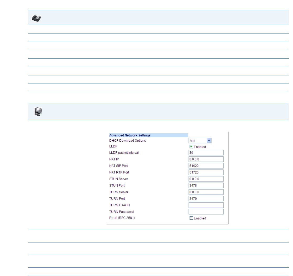
Network Settings
41-001343-02 REV04 – 05.2014 4-27
SIP and TLS Source Ports for NAT Traversal
A System Administrator can configure the SIP and TLS source ports on the IP Phone. Previously, the IP phone used default
values (5060 for UDP/TCP and 5061 for TLS). The two new parameters for configuring the SIP and TLS source ports are:
•sip local port
•sip local tls port
You can configure the SIP and TLS source ports using the configuration files or the Aastra Web UI. After configuring these
parameters, you must reboot the phone.
If NAT is disabled, the port number also shows in the VIA and Contact SIP headers.
2. Press the Advanced softkey.
3. Enter the Administrator password using the keypad. Default is “22222”.
4. Select Network > NAT.
5. In the NAT IP field, enter the public IP address of your NAT device in dotted-decimal format.
6. In the NAT SIP Port field, enter the public SIP signaling port number of your NAT device. Default is 51620.
7. In the NAT RTP Port field, enter the RTP Port number of your NAT device. Default is 51720.
8. Press the Save softkey.
9. Restart the phone for the selection to take affect.
Aastra Web UI
1. Click on Advanced Settings->Network->Advanced Network Settings.
2. Enter a NAT IP address in the "NAT IP" field. The value must be entered in dotted decimal format.
For example, 0.0.0.0. The “NAT IP” is the public IP address of your NAT device.
3. Enter a NAT port in the "NAT SIP Port" field. Default is 51620.
The “NAT SIP Port” is the public SIP signaling port number of your NAT device.
4. Enter a NAT port in the "NAT RTP Port" field. Default is 51720.
The “NAT RTP Port” is the RTP Port number of your NAT device.
5. Click Save Settings to save your settings.
IP Phone UI

Network Settings
4-28 41-001343-02 REV04 – 05.2014
If you enable NAT, the phone uses the NAT port number (and NAT IP address) in the Via and Contact SIP headers of SIP
messages, but still use the configured source port.
Configuring SIP and TLS Source Ports Using the Configuration Files
You use the following parameters to configure SIP and TLS ports for NAT traversal:
•sip local port
•sip local tls port
Note:
•By default, the IP phones use symmetric UDP signaling for outgoing UDP SIP messages. When symmetric UDP is ena-
bled, the IP phone generates and listens for UDP messages using port 5060.If symmetric UDP signaling is disabled,
the phone sends from random ports but it listens on the configured SIP local port. Refer to Symmetric UDP Signaling
on page 6-25 for more information.
•The IP phones also use symmetric TLS signaling for outgoing TLS SIP messages by default. When symmetric TLS is
enabled, the IP phone uses port 5061 as the persistent TLS connection source port. When symmetric TLS signaling is
disabled, the IP phone chooses a random persistent TLS connection source port for TLS messages from the TCP range
(i.e. 49152...65535) after each reboot regardless of whether the parameter “sip outbound support” is enabled or dis-
abled. Refer to Symmetric TLS Signaling on page 6-25 for more information.
Configuration Files
For specific parameters you can set in the configuration files, see Appendix A, the sections:
•“Local SIP UDP/TCP Port Setting” on pageA-26.
•“Local SIP TLS Port” on pageA-27.
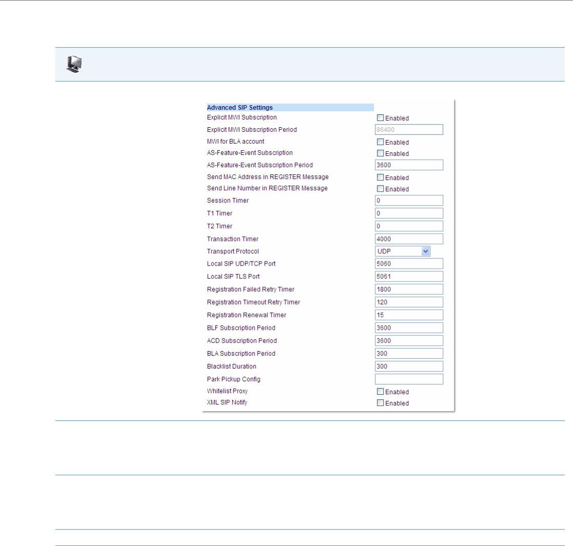
Network Settings
41-001343-02 REV04 – 05.2014 4-29
Configuring SIP and TLS Source Ports Using the Aastra Web UI
Use the following procedure to configure SIP and TLS source ports using the Aastra Web UI.
STUN and TURN Protocols
The IP phones support the following audio-path NAT Traversal features:
•Simple Traversal of User Datagram Protocol (UDP) through Network Address Translation (NAT) or also known as
STUN (RFC 3489)
and
•Traversal Using Relay NAT or also known as TURN
Aastra Web UI
1. Click on Advanced Settings->Global SIP->Advanced SIP Settings.
2. The “Local SIP UDP/TCP Port” field has a default value of 5060. Change this value if required to a value greater than 1024 and less than
65535.
Note:
It is recommended that you avoid the conflict RTP port range in case of a UDP transport.
3. The “Local SIP TLS Port” field has a default value of 5061. Change this value if required to a value greater than 1024 and less than 65535.
Note:
It is recommended that you avoid the conflict with any TCP ports being used. For example: WebUI HTTP server on 80/tcp and HTTPS on
443/tcp.
4. Click Save Settings to save your changes.

Network Settings
4-30 41-001343-02 REV04 – 05.2014
STUN is a protocol that allows the IP phones on a network to discover the presence and types of NATs and firewalls
between them and the public Internet. It also provides the ability for the phones to determine the public IP addresses
allocated to them by the NAT. STUN works with many existing NATs, and does not require any special behavior from
them. As a result, it allows the phones to work through existing NAT infrastructures.
TURN is a protocol that governs the reception of data over a connection by a single communications device operating
behind a NAT or firewall. A TURN server relays packets from an external IP address towards the IP phone only if that
phone has previously sent a packet through the same TURN server to that particular external IP address.
SIP NAT IP configurations takes precedence over the STUN/TURN configurations. Typically, the STUN/TURN configuration
is only used for media (RTP traffic) - not for signaling. (For signaling, you need to enable “Rport” if the NAT device does
not recognize SIP. For more information about “Rport”, see the section, “RPORT” on page4-52 of this release note.
The STUN/TURN configuration applies globally on the phone. If you configure both STUN and TURN on the phone, it dis-
covers what type of NAT device is between the phone and the public network. If the NAT device is full cone, restricted
cone, or port restricted cone, the phone uses STUN. If the NAT device is symmetric, the phone uses TURN.
If you configure STUN only, the phone uses STUN without the NAT discovery process.
If you configure NAT only, the phone uses NAT and does not perform the NAT discovery process during startup. TURN is
compatible with all types of NAT devices.
Limitations to Using STUN and TURN
•The Firewall type discovery process on the phone is limited to 20 seconds. If the discovery process fails, the STUN
server may not be configured correctly.
•When making a new phone call, the phone limits obtaining the port from the STUN/TURN server to 5 seconds. If the
call does not go through in 5 seconds, the phone makes the call using the Session Description Protocol (SDP) with a
local IP:port.
An Administrator can configure a STUN and/or TURN server on the IP Phones using the configuration files or the Aastra
Web UI.
Configuring STUN and TURN Servers Using the Configuration Files
Use the following parameters to configure STUN and TURN servers in your network.
•sip stun ip
•sip stun port
•sip turn ip
•sip turn port
•sip turn user
•sip turn pass
Note:
STUN does not work if the NAT device is symmetric.
Note:
The NAT IP configuration parameter takes precedence over the STUN and TURN parameters.
Configuration Files
For specific parameters you can set in the configuration files, see Appendix A, the sections:
•“SIP STUN Parameters” on pageA-27
•“SIP TURN Parameters” on pageA-28.
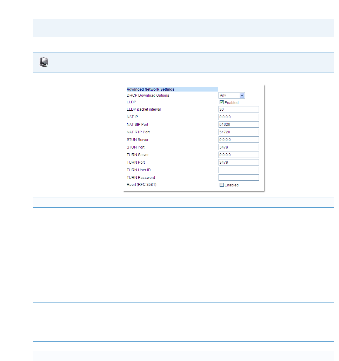
Network Settings
41-001343-02 REV04 – 05.2014 4-31
Configuring STUN and TURN Servers Using the Aastra Web UI
Use the following procedure to configure STUN and TURN servers in your network using the Aastra Web UI.
Note:
The NAT IP configuration parameter takes precedence over the STUN and TURN parameters.
Aastra Web UI
1. Click on Advanced Settings->Network->Advanced Network Settings.
Configure STUN on the IP Phone
2. In the “STUN Server” field, enter the IP address and/or qualified domain name of the STUN server in your network. You can enter up to 2 val-
ues separated by a comma. The first value is the primary and the second value is the backup. For example:
10.50.103.12, stunbackup.aastra.com.
The STUN configuration is only used for media (RTP traffic) that goes through the server - not for signaling. (For signaling, you need to enable
Rport if the NAT device does not recognized SIP).
The STUN configuration applies globally to each phone.
If you configure both STUN and TURN on the phone, it discovers what type of NAT device is between the phone and the public network. If
the NAT device is full cone, restricted cone, or port restricted cone, the phone uses STUN. If the NAT device is symmetric, the phone uses
TURN. If you configure STUN only, the phone uses STUN without the NAT discovery process.
Notes:
•The NAT IP configuration parameter takes precedence over the STUN parameters.
•STUN does not work if the NAT device is symmetric.
3. In the “STUN Port” field, enter the port number of the STUN server. You can enter up to 2 values separated by a comma. The first value is the
primary and the second value is the backup. For example:
3478,3479
Default is 3478. Range of values are 0 to 65535.
4. Click Save Settings to save your changes.
Configure TURN on the IP Phone

Network Settings
4-32 41-001343-02 REV04 – 05.2014
Interactive Connectivity Establishment (ICE) Support
The phones now support the Interactive Connectivity Establishment (ICE) Protocol. ICE makes use of the Session Traver-
sal Utilities for NAT (STUN) protocol and its extension, Traversal Using Relay NAT (TURN).
In an ICE environment, two agent endpoints (or two phones communicating at different locations) are able to communi-
cate via the SIP Protocol by exchanging Session Description Protocol (SDP) messages. At the beginning of the ICE proc-
ess, the agents are ignorant of their own topologies. In particular, they might or might not be behind a NAT (or multiple
tiers of NATs).
ICE allows the agents to discover enough information about their topologies to potentially find one or more paths by
which they can communicate.
The ICE Protocol is automatically enabled if both STUN and TURN servers are configured in the network. The following
occurs when ICE is used on the phone:
•The TURN address/port is always used as the preferred media address in initial INVITES.
•Media is sent through the TURN server prior to the completion of the ICE connectivity check.
•A Re-INVITE is used to adjust media (if required) after the ICE connectivity check is complete.
•When ICE is enabled, call hold is performed via the send only attribute instead of changing the media address to
0.0.0.0.
•The ICE Protocol supports the RTCP SDP attribute (RFC 3605)
STUN and TURN can be enabled using the Aastra Web UI or the configuration files. This automatically enables ICE.
5. In the “TURN Server” field, enter the IP address and/or qualified domain name of the TURN server in your network. You can enter up to 2 val-
ues separated by a comma. The first value is the primary and the second value is the backup. For example:
10.50.103.12, turnbackup.aastra.com.
The TURN configuration is only used for media (RTP traffic) that goes through the server - not for signaling. (For signaling, you need to enable
Rport if the NAT device does not recognized SIP).
The TURN configuration applies globally to each phone.
If you configure both STUN and TURN on the phone, it discovers what type of NAT device is between the phone and the public network. If
the NAT device is full cone, restricted cone, or port restricted cone, the phone uses STUN. If the NAT device is symmetric, the phone uses
TURN. If you configure TURN only, the phone uses TURN with the NAT discovery process. TURN is compatible with all types of NAT devices
but can be costly since all traffic goes through a media relay (which can be slow, can exchange more messages, and requires the TURN server
to allocate bandwidth for calls).
Note:
The NAT IP configuration parameter takes precedence over the STUN and TURN parameters.
6. In the “TURN Port” field, enter the port number of the TURN server. You can enter up to 2 values separated by a comma. The first value is the
primary and the second value is the backup. For example:
3479,3480
Default is 3479. Range of values are 0 to 65535.
7. (Optional) In the “TURN User ID” field, enter the username that a user must enter when accessing an account on the TURN server. For exam-
ple, 0412919146.
Valid values are up to 63 alphanumeric characters.
8. (Optional) In the “TURN Password” field, enter the password that a user must enter when accessing an account on the TURN server. For
example, 42447208233b8b8b8a234.
Valid values are up to 63 alphanumeric characters.
9. Click Save Settings to save your changes.
Aastra Web UI

Network Settings
41-001343-02 REV04 – 05.2014 4-33
Reference
To configure STUN and TURN (which automatically enables ICE), see “Configuring STUN and TURN Servers Using the Con-
figuration Files” on page4-30 and “Configuring STUN and TURN Servers Using the Aastra Web UI” on page4-31.
HTTPS Client/Server Configuration
HTTPS is a Web protocol that encrypts and decrypts user page requests as well as the pages that are returned by the Web
server. HTTPS uses Secure Socket Layer (SSL) or Transport Layer Security (TLS) as a sublayer under its regular HTTP applica-
tion layering. SSL is a commonly-used protocol for managing the security of a message transmission on the Internet. It
uses a 40-bit key size for the RC4 stream encryption algorithm, which is considered an adequate degree of encryption for
commercial exchange. TLS is a protocol that ensures privacy between communicating applications and their users on the
Internet. When a server and client communicate, TLS ensures that no third party may eavesdrop or tamper with any mes-
sage. TLS is the successor to SSL.
When an HTTPS client opens and closes its TCP socket, the SSL software respectively handshakes upon opening and dis-
connects upon closing from the HTTPS server. The main HTTPS client functions are:
•Downloading of configuration files and firmware images.
•Downloading of script files based on an “HTTPS://” URL supplied by a softkey definition.
The HTTPS server provides HTTP functionality over secure connections. It coexists with the HTTP server but has its own set
of tasks. The main HTTPS server functions are:
•Delivery of web page content to a browser client over a secure connection.
•Execution of HTTP GET and POST requests received over a secure connection.
Using the configuration files, the IP phone UI, or the Aastra Web UI, you can configure the following regarding HTTPS:
•Specify HTTPS security client method to use (TSLv1 or SSLv3)
•Enable or disable HTTP to HTTPS server redirect function
•HTTPS server blocking of XML HTTP POSTS to the phone
Configuring HTTPS Client and Server Settings
Use the following procedures to configure the HTTPS client and server for the IP phones.
Note:
HTTPS uses port 443 instead of HTTP port 80 in its interactions with the TCP/IP lower layer.
Note:
To enable or disable the IP phones to use the HTTPS protocol as the configuration server, see the section, “Configuring
the Configuration Server Protocol” on page4-87.
Configuration Files
For specific parameters you can set in the configuration files, see Appendix A, the section, “HTTPS Client and Server Settings” on pageA-30.

Network Settings
4-34 41-001343-02 REV04 – 05.2014
IP Phone UI
1. Press on the phone to enter the Options List.
2. Select Administrator Menu.
3. Enter your Administrator password.
Note:
The IP Phones accept numeric passwords only.
4. Select Configuration Server.
5. Select HTTPS Settings.
Configure HTTPS Client
6. Select HTTPS Client.
7. Select Client Method.
8. Press Change to select a client method to use for HTTPS. Valid values are:
•SSL 3.0 (default)
•TLS 1.0
9. Press Done to save the changes.
Configure HTTPS Server
10. Select HTTPS Server.
11. Select HTTP->HTTPS.
12. Press Change to select “Yes” or “No”. D ef au lt is “ No”.
Enabling this feature redirects the HTTP protocol to HTTPS.
13. Press Done to save the changes.
14. Select XML HTTP POSTs.
15. Press Change to select “Yes” or “No”. D ef au lt is “ No”.
Enabling this feature blocks XML HTTP POSTs from the IP Phone.
16. Press Done (4 times) to finish.
Note:
The session prompts you to restart the IP phone to apply the configuration settings.
17. Select Restart.

Network Settings
41-001343-02 REV04 – 05.2014 4-35
For 6739i:
For 6867i:
IP Phone UI
1. Press the Options key on the phone to enter the Options List.
2. Press Advanced. A keyboard displays.
3. Enter the Administrator password using the keyboard. Default is “22222”.
4. Press Cfg. Svr.
5. Press HTTPS.
Configure HTTPS Client
6. Press HTTPS Client Method.
7. Press a client method value to use for HTTPS. Valid values are:
•SSL 3.0 (default)
•TLS 1.0
8. Press Done to save the changes.
Configure HTTPS Server
9. Press HTTPS Server.
10. Enter the IP address of the HTTPS server in the text box. Enabling this feature redirects the HTTP protocol to HTTPS.
11. Press until the Options List screen displays.
12. Press Restart to restart the phone for the change to take affect.
IP Phone UI
1. Press on the phone to enter the Options List.
2. Press the Advanced softkey.
3. Enter the Administrator password using the keypad. Default is “22222”.
4. Select Configuration Server.
5. In the Download Protocol field, select HTTPS.
Configure HTTPS Client
6. In the HTTPS Client Method field, press a client method value to use for HTTPS. Valid values are:
•SSL 3.0 (default)
•TLS 1.0
Configure HTTPS Server
7. In the HTTPS Server field, enter the IP address of the HTTPS server in the text box. Enabling this feature redirects the HTTP protocol to
HTTPS.
8. Press the Save softkey.
9. Restart the phone for the selection to take affect.
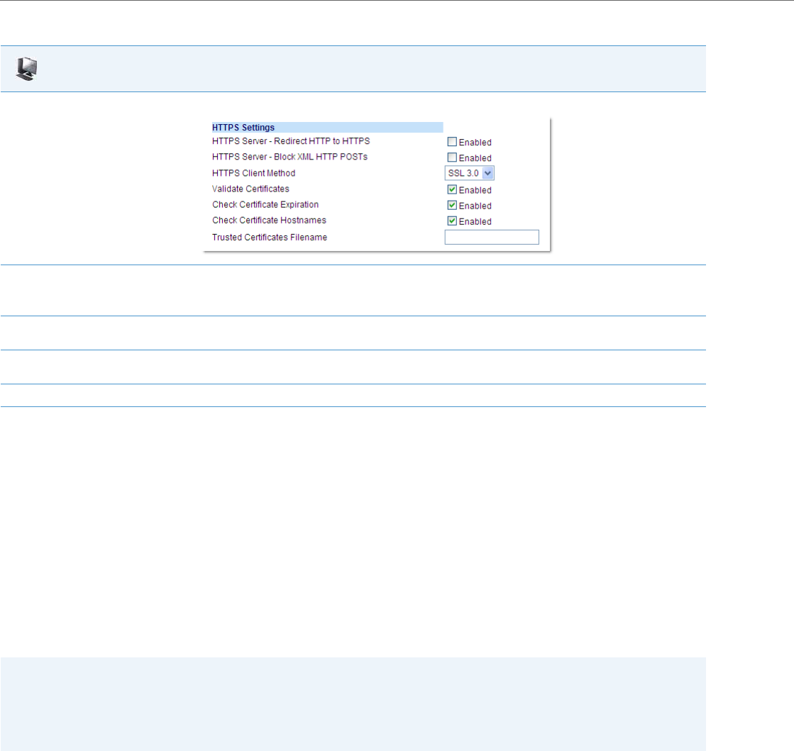
Network Settings
4-36 41-001343-02 REV04 – 05.2014
HTTPS Server Certificate Validation
The HTTPS client on the IP Phones support validation of HTTPS certificates. This feature supports the following:
•Verisign, GeoTrust, Thawte, Comodo, Entrust, and CyberTrust signed certificates
•User-provided certificates
•Checking of hostnames
•SSL Wildcard certificate (i.e. SSL certificate specifying the Common Name as a wildcard [e.g. CN=*.company.com]) sup-
port.
•Checking of certificate expiration
•Ability to disable any or all of the validation steps
•Phone displays a message when a certificate is rejected (except on check-sync operations)
All validation options are enabled by default.
Certificate Management
Aastra Provided Certificates
The phones come with root certificates from Verisign, GeoTrust, Thawte, Comodo, Entrust, and CyberTrust pre-loaded.
User Provided Certificates
Aastra Web UI
1. Click on Advanced Settings->Network->HTTPS Settings.
2. Select an HTTPS client method to use from the HTTPS Client Method field. Valid values are:
•SSL 3.0 (default)
•TSL 1.0
3. Enable HTTP to HTTPS redirect by checking the HTTPS Server - Redirect HTTP to HTTPS field check box. (Disable this field by unchecking
the check box). Default is disabled.
4. Enable the blocking of XML HTTP POSTs by the HTTPS server by checking the HTTPS Server - Block XML HTTP POSTs field check box. (Dis-
able this field by unchecking the check box). Default is disabled.
5. Click Save Settings to save your settings.
Note:
The IP Phones do not support the transmission of HTTPS client certificates for validation by HTTPS servers. If the IP
Phone attempts to download files from an HTTPS server that requires a client certificate during a file download trans-
action, a “No Certificate” error will occur and be logged on the IP Phone (viewable under the Options->Phone Status
->Error Messages menu in the IP Phone UI or on the Troubleshooting page of the respective IP Phone’s Web UI).

Network Settings
41-001343-02 REV04 – 05.2014 4-37
The administrator has the option to upload their own certificates onto the phone. The phone downloads these certificates
in a file of .PEM format during boot time after configuration downloads. The user-provided certificates are saved on the
phone between firmware upgrades but are deleted during a factory default. The download of the user-provided certifi-
cates are based on a filename specified in the configuration parameter, https user certificates (Trusted Certificates
Filename in the Aastra Web UI; user-provided certificates are not configurable via the IP Phone UI).
Certificate Validation
Certificate validation is enabled by default. Validation occurs by checking that the certificates are well formed and signed
by one of the certificates in the trusted certificate set. It then checks the expiration date on the certificate, and finally, com-
pares the name in the certificate with the address for which it was connected.
If any of these validation steps fail, the connection is rejected. Certificate validation is controlled by three parameters
which you can configure via the configuration files, the IP Phone UI, or the Aastra Web UI:
•https validate certificates - Enables/disables validation.
•https validate hostname - Enables/disables the checking of the certificate commonName against the server name.
•https validate expires - Enables/disables the checking of the expiration date on the certificate.
User Interface
Certificate Rejection
When the phone rejects a certificate, it displays, "Bad Certificate" on the LCD.
Note:
Certificates that are signed by providers other than Verisign, GeoTrust or Thawte do not verify on the phone by default.
The user can overcome this by adding the root certificate of their certificate provider to the use-provided certificate
.PEM file.

Network Settings
4-38 41-001343-02 REV04 – 05.2014
For Verisign Certificate Rejection
The phones support 2048-bit Verisign certificates. In case of a certificate error, detailed descriptions can be found from
the error message list in the phone status menu.
The following error descriptions are now available:
•No Certificate
•Bad Certificate
•Unsupported Certificate
•Certificate Revoked
•Certificate Expired
•Certificate Unknown
Configuring HTTPS Server Certificate Validation
An Administrator can configure HTTPS Server Certificate Validation using the configuration files, the IP Phone UI, or the
Aastra Web UI. Use the following procedures to configure the HTTPS server certificate validation on the IP phones.
Configuration Files
For specific parameters you can set in the configuration files, see Appendix A, the section, “HTTPS Server Certificate Validation Settings” on pageA-31.
IP Phone UI
1. Press Options, and then select Administrator Menu.
2. Select Configuration Server.
3. Select HTTPS Settings->Cert. Validation.
The following list displays:
•Enable
•Check Expires
•Check Hostnames
Enable/Disable HTTPS Server Certificate Validation
4. Select Enable.
5. Press Change to toggle the “Enable” field to “Yes” or “No”.
Note:
If you are using HTTPS as a configuration method, and use a self signed certificate, you must set this field to “No” before upgrading to
Release 2.3 of the IP Phones.
6. Press DONE to save the change and return to the Certificates screen.
Note:
This change is immediately applied after pressing DONE.
Enable/Disable HTTPS Validate Certificate Expiration
7. Select Check Expires.
8. Press Change to toggle the “Check Expires” field to “Yes” or “No”.
Notes:
•This change is immediately applied after pressing DONE.
•If the “Check Expires” parameter is set to Yes, the clock on the phone must be set for the phone to accept the certificates.
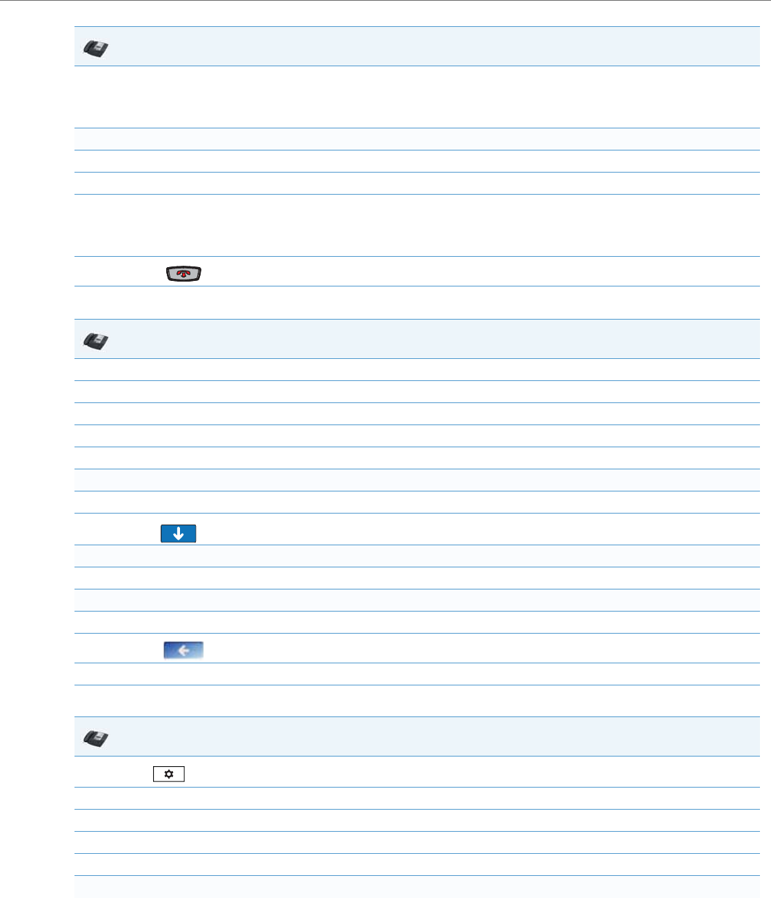
Network Settings
41-001343-02 REV04 – 05.2014 4-39
For 6739i:
For 6867i:
9. Press DONE to save the change and return to the Certificates screen.
Note:
This change is immediately applied after pressing DONE.
Enable/Disable HTTPS Validate Hostname
10. Select Check Hostnames.
11. Press Change to toggle the “Check Hostnames” field to “Yes” or “No”.
12. Press DONE to save the change and return to the Certificates screen.
Note:
This change is immediately applied after pressing DONE.
13. Press to exit the Options Menu and return to the idle screen.
IP Phone UI
1. Press the Options key on the phone to enter the Options List.
2. Press Advanced. A keyboard displays.
3. Enter the Administrator password using the keyboard. Default is “22222”.
4. Press Cfg. Svr.
5. Press HTTPS.
Enable/Disable HTTPS Server Certificate Validation
6. Press Cert. Validation, and select Enable.
7. Press to scroll to the next screen.
Enable/Disable HTTPS Validate Certificate Expiration
8. Press Check Expires, and select Enable.
Enable/Disable HTTPS Validate Hostname
9. Press Check Hostnames, and select Enable.
10. Press until the Options List screen displays.
11. Press Restart to restart the phone for the change to take affect.
IP Phone UI
1. Press on the phone to enter the Options List.
2. Press the Advanced softkey.
3. Enter the Administrator password using the keypad. Default is “22222”.
4. Select Configuration Server.
5. In the Download Protocol field, select HTTPS.
Enable/Disable HTTPS Server Certificate Validation
IP Phone UI
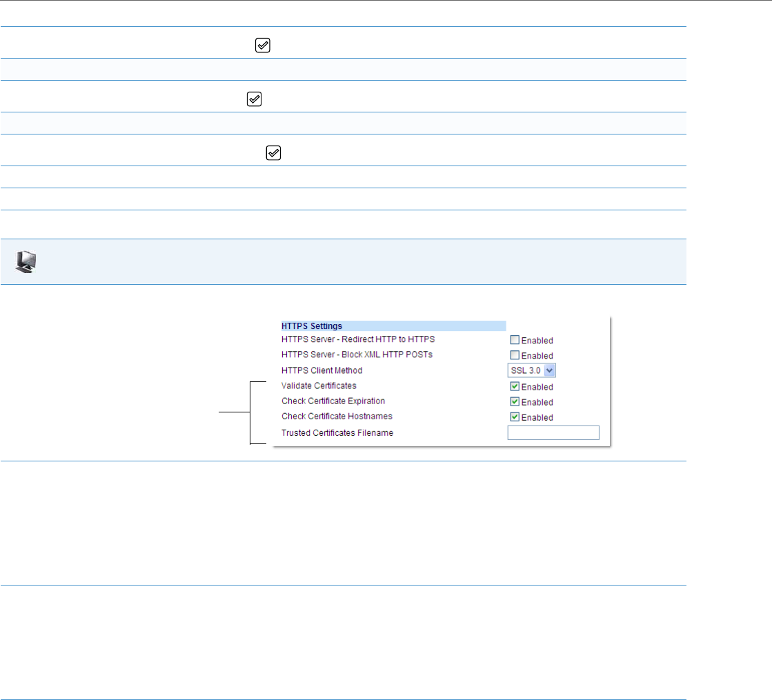
Network Settings
4-40 41-001343-02 REV04 – 05.2014
6. In the Cert. Validation checkbox, press the button to enable the feature.
Enable/Disable HTTPS Validate Certificate Expiration
7. In the Check Expires checkbox, press the button to enable the feature.
Enable/Disable HTTPS Validate Hostname
8. In the Check Hostnames checkbox, press the button to enable the feature.
9. Press the Save softkey.
10. Restart the phone for the selection to take affect.
Aastra Web UI
1. Click on Advanced Settings->Network->HTTPS Settings.
2. The “Validate Certificates” field is enabled by default. To disable validation of certificates, click the check mark in the box to clear the
check mark.
When this parameter is enabled, the HTTPS client performs validation on SSL certificates before accepting them.
Notes:
•This parameter is immediately applied after clicking the SAVE SETTINGS button.
• If you are using HTTPS as a configuration method, and use a self signed certificate, you must disable (uncheck) this field before
upgrading to Release 2.3 of the IP Phones.
3. The “Check Certificate Expiration” field is enabled by default. To disable validation of certificate expiration, click the check mark in the box
to clear the check mark.
When this parameter is enabled, the HTTPS client verifies whether or not a certificate has expired prior to accepting the certificate.
Notes:
•This parameter is immediately applied after clicking the SAVE SETTINGS button.
•If the “Check Certificates Expiration” parameter is set to Yes , the clock on the phone must be set for the phone to accept the certificates.
4. The “Check Certificate Hostnames” field is enabled by default. To disable validation of hostnames, click the check mark in the box to clear
the check mark.
Note:
This parameter is immediately applied after clicking the SAVE SETTINGS button.
HTTPS Validation
Certificate
Parameters

Network Settings
41-001343-02 REV04 – 05.2014 4-41
Virtual LAN (optional)
Virtual Local Area Network (VLAN) is a feature on the IP phone that allows for multiple logical Ethernet interfaces to send
outgoing RTP packets over a single physical Ethernet as described in IEEE Std 802.3. On the IP phone, you configure a
VLAN ID that associates with the physical Ethernet port.
By configuring specific VLAN parameters, the IP phones have the capability of adding and removing tags, and processing
the ID and priority information contained within the tag.
VLAN on the IP phones is disabled by default. When you enable VLAN, the IP phone provides defaults for all VLAN param-
eters. If you choose to change these parameters, you can configure them using the configuration files, the IP Phone UI, or
the Aastra Web UI.
The following sections describe the VLAN features you can configure on the IP phones.
Type of Service (ToS), Quality of Service (QoS), and DiffServ QoS
ToS is an octet as a field in the standard IP header. It is used to classify the traffic of the different QoSs.
QoS provides service differentiation between IP packets in the network. This service differentiation is noticeable during
periods of network congestion (for example, in case of contention for resources) and results in different levels of network
performance.
Port 0 is the Ethernet LAN Port connected to the network. Port 1 is the Ethernet PC Port used for passthrough to a PC.
Differentiated Service (DiffServ) QoS is class-based where some classes of traffic receive preferential handling over other
traffic classes.
The Differentiated Services Code Point (DSCP) value is stored in the first six bits of the ToS field. Each DSCP specifies a par-
ticular per-hop behavior that is applied to a packet.
The following parameters allow an administrator to configure ToS, QoS, and DiffServ QoS for VLAN:
5. If you require the download of User-provided certificates in a .PEM formatted file, enter the file name in the format <filename.pem> in the
“Trusted Certificates Filename” field. For example:
trustedCerts.pem
This parameter specifies a file name for a .PEM file located on the configuration server. This file contains the User-provided certificates in
PEM format. These certificates are used to validate peer certificates.
Notes:
•You must disable the “Validate Certificates” field in order for the phone to accept the User-provided certificates.
•This parameter requires you restart the phone in order for it to take affect.
6. Click Save Settings to save your changes.
7. If you entered a filename in the “Trusted Certificates Filename” field, click on Operation->Reset, and restart the phone for the changes
to take affect.
Note:
All latest VLAN functionality is backwards compatible with IP Phone Releases 1.3 and 1.3.1.
Parameters in Configuration Files Parameters in Aastra Web UI
Global
tagging enabled VLAN Enable
priority non-ip Priority, Non-IP Packet
vlan hpq HPQ Enable
Aastra Web UI

Network Settings
4-42 41-001343-02 REV04 – 05.2014
DSCP Range/VLAN Priority Mapping
DSCP bits in the ToS field of the IP header are set for RTP, RTCP, and SIP packets using either the default values or the val-
ues configured via the "tos sip", "tos rtp", and " tos rtcp" parameters.
When the VLAN global configuration parameter, "tagging enabled" is set to 1, VLAN priority for IP packets is mapped to
the DSCP value instead of a single priority for all packets. An administrator can also configure VLAN priority for non-IP
packets using the "priority non-ip" parameter.
Since the default DSCP settings for SIP, RTP, and RTCP are 26, 46, and 46 respectively, this results in corresponding default
VLAN priorities of 3 for SIP, 5 for RTP, and 5 for RTCP (based on the settings in the table “DSCP Range/VLAN Priority Map-
ping” on page4-42).
You can change the default parameters by modifying just the DSCP values, just the VLAN priority values, or by modifying
all values.
LAN Port
vlan id VLAN ID
tos priority map SIP Priority
tos priority map RTP Priority
tos priority map RTCP Priority
PC Port
vlan id port 1 VLAN ID
QoS eth port 1 priority Priority
Notes:
•In order for the software to successfully maintain connectivity with a network using VLAN functionality, the IP phone
reboots if you modify the "tagging enabled" (VLAN Enable in the Web UI), "vlan id", or "vlan id port 1" parameters.
•Setting the LAN Port VLAN ID (vlan id) to 4095 and PC Port VLAN ID (vlan id port 1) to any ID from 1 to 4094 will allow
frames from the PC Port (containing a VLAN ID) to be untagged before being forwarded to the LAN Port and frames
from the LAN Port (without a VLAN ID) to be tagged with the configured VLAN ID before being forwarded to the PC
Port. For configuring this feature via the Phone UI and the Aastra Web UI, see “Configuring VLAN (optional)” on
page4-45. For configuring this feature using the configuration files, see Appendix A, the section, “Virtual Local Area
Network (VLAN) Settings” on page A-34.
•Alternatively setting the LAN Port VLAN ID (vlan id) to any ID from 1 to 4094 and PC Port VLAN ID (vlan id port 1) to
4095 will allow frames from the LAN Port (containing a VLAN ID) to be untagged before being forwarded to the PC
Port and frames from the PC Port (without a VLAN ID) to be tagged with the configured VLAN ID before being for-
warded to the LAN Port. For configuring this feature via the Phone UI and the Aastra Web UI, see “Configuring VLAN
(optional)” on page4-45. For configuring this feature using the configuration files, see Appendix A, the section, “Vir-
tual Local Area Network (VLAN) Settings” on page A-34.
Parameters in Configuration Files Parameters in Aastra Web UI

Network Settings
41-001343-02 REV04 – 05.2014 4-43
The following table shows the DSCP range/VLAN priority mapping:
The following table identifies the default DSCP values for the protocols:
Configuring Type of Service (ToS)/DSCP (optional)
Use the following procedures to configure ToS/DSCP on the IP phone.
DSCP Range VLAN Priority
0-7 0
8-15 1
16-23 2
24-31 3
32-39 4
40-47 5
48-55 6
56-63 7
Protocol Name Default DSCP Values in the ToS Field
sip 26
rtp 46
rtcp 46
Note:
ToS/DSCP is enabled by default. The SIP, RTP, and RTCP parameters show defaults of 26, 46, and 46, respectively. Use the
following procedures to change these settings if required.
Configuration Files
For specific parameters you can set in the configuration files, see Appendix A, the section, “Type of Service (ToS)/DSCP Settings” on pageA-39.
IP Phone UI
1. Press on the phone to enter the Options List.
2. Select Administrator Menu.
3. Enter your Administrator password.
Note:
The IP Phones accept numeric passwords only.
4. Select Network Settings.
5. Select Type of Service DSCP.
6. Select Type of Service SIP.
or
Select Type of Service RTP.
or
Select Type of Service RTCP.
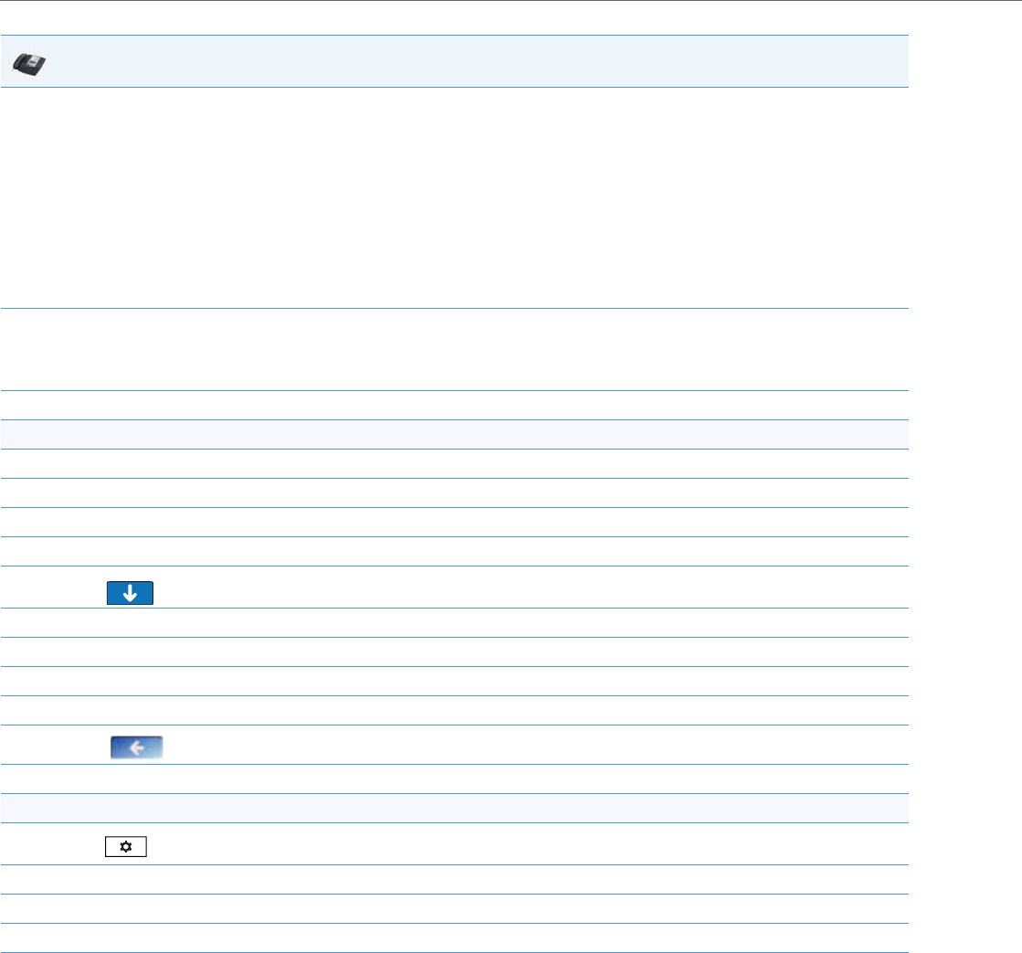
Network Settings
4-44 41-001343-02 REV04 – 05.2014
7. Enter a value for “Type of Service SIP”. D e fa u lt i s 26.
or
Enter a value for “Type of Service RTP”. D e f au lt i s 46.
or
Enter a value for “Type of Service RTCP”. D e f a ul t i s 46.
Valid values are 0 to 63.
Note:
If you change the ToS/DSCP setting for a Protocol, and VLAN is enabled, you will need to map the applicable priority to the Protocol setting
as shown in the first table in “DSCP Range/VLAN Priority Mapping” on page4-42 For more information, see the section “Configuring VLAN
(optional)” on page4-45.
8. Press Done (3 times) to save the changes.
Note:
The session prompts you to restart the IP phone to apply the configuration settings
9. Select Restart.
For the 6739i:
1. Press the Options key on the phone to enter the Options List.
2. Press Advanced. A keyboard displays.
3. Enter the Administrator password using the keyboard. Default is “22222”.
4. Press Network.
5. Press to scroll to the next screen.
6. Press Type of Service DSCP.
7. Press Type of Service SIP, and then enter a value for ToS. Default is 26.
8. Press Type of Service RTP, and then enter a value for ToS. Default is 46.
9. Press Type of Service RTCP, and then enter a value for ToS. Default is 46.
10. Press until the Options List screen displays.
11. Press Restart to restart the phone for the change to take affect.
For the 6867i:
1. Press on the phone to enter the Options List.
2. Press the Advanced softkey.
3. Enter the Administrator password using the keypad. Default is “22222”.
4. Select Network > DSCP.
5. Enter a value for “Type of Service SIP”. D e fa u lt i s 26.
or
Enter a value for “Type of Service RTP”. D e f au lt i s 46.
or
Enter a value for “Type of Service RTCP”. D e f a ul t i s 46.
Valid values are 0 to 63.
Note:
If you change the ToS/DSCP setting for a Protocol, and VLAN is enabled, you will need to map the applicable priority to the Protocol setting
as shown in the first table in “DSCP Range/VLAN Priority Mapping” on page4-42 For more information, see the section “Configuring VLAN
(optional)” on page4-45.
IP Phone UI
Network Settings
41-001343-02 REV04 – 05.2014 4-45
Configuring VLAN (optional)
Use the following procedures to configure VLAN on the IP phone.
6. Press the Save softkey.
7. Restart the phone for the selection to take affect.
Aastra Web UI
1. Click on Advanced Settings->Network->Type of Service DSCP.
2. Select a Protocol field:
•“SIP”
or
•“RTP”
or
•“RTCP”
3. Enter a value from 0 to 63. Default values are as follows:
•SIP = 26
•RTP = 46
•RTCP = 46
Note:
If you change the ToS/DSCP setting for a Protocol, and VLAN is enabled, you will need to map the applicable priority to the Protocol setting
as shown in the first table in “DSCP Range/VLAN Priority Mapping” on page4-42. For more information, see the section “Configuring VLAN
(optional)” on page4-45.
4. Click Save Settings to save your settings.
Notes:
•VLAN is disabled by default. When you enable VLAN, the IP phones use the default settings for each VLAN parameter.
You can change the default settings if required using the following procedure.
•PC Port parameters are not applicable to the 6730i IP Phone.
Configuration Files
For specific parameters you can set in the configuration files, see Appendix A, the section, “Virtual Local Area Network (VLAN) Settings” on pageA-34.
IP Phone UI
1. Press on the phone to enter the Options List.
2. Select Admin Menu.
IP Phone UI

Network Settings
4-46 41-001343-02 REV04 – 05.2014
3. Enter your Administrator password.
Note:
The IP Phones accept numeric passwords only.
4. Select Network Settings.
5. Select Ethernet and VLAN.
To globally enable/disable VLAN and set priority for non-IP packets:
6. Select VLAN Settings.
7. Select VLAN.
8. Select Enable.
9. Press Done or Set to save the changes.
10. Select LAN Port VLAN.
11. Select Other Priority and enter a non-IP priority value from 0 to 7 for non-IP packets.
Default for this field is 5.
12. Press Done (2 times) to return to the VLAN Settings menu.
To set VLAN ID and priority for LAN Port (Port 0):
13. Select LAN Port VLAN.
14. Select LAN Port VLAN ID and enter a value from 1 to 4095 to specify the VLAN ID for the LAN Port.
Default is 1.
Note:
Setting the LAN Port VLAN ID to 4095 and PC Port VLAN ID to any ID from 1 to 4094 will allow frames from the PC port (containing a VLAN
ID) to be untagged before being forwarded to the LAN port and frames from the LAN port (without a VLAN ID) to be tagged with the con-
figured VLAN ID before being forwarded to the PC port.
Example:
You enable tagging on the phone port as normal but set the LAN Port VLAN ID to 4095 and the PC Port VLAN ID to any ID from 1 to 4094. The
following example sets the PC port to be on VLAN 3 but the LAN port is configured as untagged.
VLAN Settings->VLAN: Enable
VLAN Settings->LAN Port VLAN->LAN Port VLAN ID: 4095
VLAN Settings->PC Port VLAN->PC Port VLAN ID: 3
15. Press Enter or Set to save the change.
16. Select VLAN Priority.
17. Select one of the following VLAN Protocols:
•SIP Priority
•RTP Priority
•RTCP Priority
18. Enter a VLAN priority value from 0 to 7 for the associated Protocol. Default values for each Protocol are:
SIP Priority = 3
RTP Priority = 5
RTCP Priority = 5
19. Press Done (2 times) to return to the VLAN Settings menu.
To set VLAN ID and priority for PC Port (Port 1):
20. Select PC Port VLAN.
Note:
PC Port parameters are not applicable to the 6730i IP Phone.
IP Phone UI

Network Settings
41-001343-02 REV04 – 05.2014 4-47
21. Select PC Port VLAN ID and enter a value from 1 to 4095 to specify the VLAN ID for the PC Port.
Default is 4095.
Note:
Setting the PC Port VLAN ID to 4095 and LAN Port VLAN ID to any ID from 1 to 4094 will allow frames from the LAN port (containing a VLAN
ID) to be untagged before being forwarded to the PC port and frames from the PC port (without a VLAN ID) to be tagged with the config-
ured VLAN ID before being forwarded to the LAN port.
Example:
You enable tagging on the phone port as normal but set the PC Port VLAN ID to 4095 and the LAN Port VLAN ID to any ID from 1 to 4094.
The following example sets the LAN port to be on VLAN 3 but the PC port is configured as untagged.
VLAN Settings->VLAN: Enable
VLAN Settings->LAN Port VLAN->LAN Port VLAN ID: 3
VLAN Settings->PC Port VLAN->PC Port VLAN ID: 4095
22. Press Enter or Set to save the change.
23. Select PC Port Priority.
24. Select a PC Port VLAN priority value from 0 to 7 for the PC Port.
Default is 0.
25. Press Done to save the changes.
26. Navigate back to the Options List menu.
27. Select Restart Phone and follow the prompts to restart the phone and apply the configuration changes.
IP Phone UI
Network Settings
4-48 41-001343-02 REV04 – 05.2014
For the 6739i:
IP Phone UI
1. Press the Options key on the phone to enter the Options List.
2. Press Advanced. A keyboard displays.
3. Enter the Administrator password using the keyboard. Default is “22222”.
4. Press Network.
5. Press to scroll to the next screen.
6. Press Ethernet & VLAN.
To globally enable/disable VLAN and set priority for non-IP packets:
7. Press VLAN Settings.
8. Press the VLAN Disable/Enable button, and then press Enable.
9. Select LAN Port VLAN.
10. Select Other Priority and enter a non-IP priority value from 0 to 7 for non-IP packets.
Default for this field is 5.
11. Press to return to the VLAN screen.
To set VLAN ID and priority for LAN Port (Port 0):
12. Press LAN Port VLAN.
13. Press LAN Port VLAN ID and then enter a value from 1 to 4095 to specify the VLAN ID for the LAN Port. Default is 1.
Note:
Setting the LAN Port VLAN ID to 4095 and PC Port VLAN ID to any ID from 1 to 4094 will allow frames from the PC port (containing a VLAN
ID) to be untagged before being forwarded to the LAN port and frames from the LAN port (without a VLAN ID) to be tagged with the con-
figured VLAN ID before being forwarded to the PC port.
Example:
You enable tagging on the phone port as normal but set the LAN Port VLAN ID to 4095 and the PC Port VLAN ID to any ID from 1 to 4094. The
following example sets the PC port to be on VLAN 3 but the LAN port is configured as untagged.
VLAN Settings->VLAN: Enable
VLAN Settings->LAN Port VLAN->LAN Port VLAN ID: 4095
VLAN Settings->PC Port VLAN->PC Port VLAN ID: 3
14. Press SIP Priority and then enter a value from 0 to 7 to specify the SIP priority for the LAN Port. Default is 3.
15. Press RTP Priority and then enter a value from 0 to 7 to specify the RTP priority for the LAN Port. Default is 5.
16. Press RTCP Priority and then enter a value from 0 to 7 to specify the RTCP priority for the LAN Port. Default is 5.
17. Press to return to the VLAN screen.
To set VLAN ID and priority for PC Port (Port 1):
18. Press PC Port VLAN.
Network Settings
41-001343-02 REV04 – 05.2014 4-49
For the 6867i:
19. Press PC Port VLAN ID and then enter a value from 1 to 4095 to specify the VLAN ID for the LAN Port. Default is 4095.
Note:
Setting the PC Port VLAN ID to 4095 and LAN Port VLAN ID to any ID from 1 to 4094 will allow frames from the LAN port (containing a VLAN
ID) to be untagged before being forwarded to the PC port and frames from the PC port (without a VLAN ID) to be tagged with the configured
VLAN ID before being forwarded to the LAN port.
Example:
You enable tagging on the phone port as normal but set the PC Port VLAN ID to 4095 and the LAN Port VLAN ID to any ID from 1 to 4094. The
following example sets the LAN port to be on VLAN 3 but the PC port is configured as untagged.
VLAN Settings->VLAN: Enable
VLAN Settings->LAN Port VLAN->LAN Port VLAN ID: 3
VLAN Settings->PC Port VLAN->PC Port VLAN ID: 4095
20. Press Priority and then enter a value from 0 to 7 to specify the PC Port VLAN priority. Default is 0.
21. Press until the Options List screen displays.
22. Press Restart to restart the phone for the change to take affect.
IP Phone UI
1. Press on the phone to enter the Options List.
2. Press the Advanced softkey.
3. Enter the Administrator password using the keypad. Default is “22222”.
4. Select Network > VLAN.
To globally enable/disable VLAN and set priority for non-IP packets:
5. In the Basic Settings > VLAN field enable VLAN by pressing the right navigation key.
6. In the LAN Port VLAN > Other Priority field, change the non-IP priority value from 0 to 7 for non-IP packets.
Default for this field is 5.
To set VLAN ID and priority for LAN Port (Port 0):
7. In the LAN Port VLAN > LAN Port VLAN ID field, enter a value from 1 to 4095 to specify the VLAN ID for the LAN Port. Default is 1.
Note:
Setting the LAN Port VLAN ID to 4095 and PC Port VLAN ID to any ID from 1 to 4094 will allow frames from the PC port (containing a VLAN
ID) to be untagged before being forwarded to the LAN port and frames from the LAN port (without a VLAN ID) to be tagged with the con-
figured VLAN ID before being forwarded to the PC port.
Example:
You enable tagging on the phone port as normal but set the LAN Port VLAN ID to 4095 and the PC Port VLAN ID to any ID from 1 to 4094. The
following example sets the PC port to be on VLAN 3 but the LAN port is configured as untagged.
VLAN Settings->VLAN: Enable
VLAN Settings->LAN Port VLAN->LAN Port VLAN ID: 4095
VLAN Settings->PC Port VLAN->PC Port VLAN ID: 3
8. In the LAN Port VLAN > SIP Priority field, enter a value from 0 to 7 to specify the SIP priority for the LAN Port. Default is 3.
9. In the LAN Port VLAN > RTP Priority field, enter a value from 0 to 7 to specify the RTP priority for the LAN Port. Default is 5.
10. In the LAN Port VLAN > RTCP Priority field, enter a value from 0 to 7 to specify the RTCP priority for the LAN Port. Default is 5.
To set VLAN ID and priority for PC Port (Port 1):
IP Phone UI
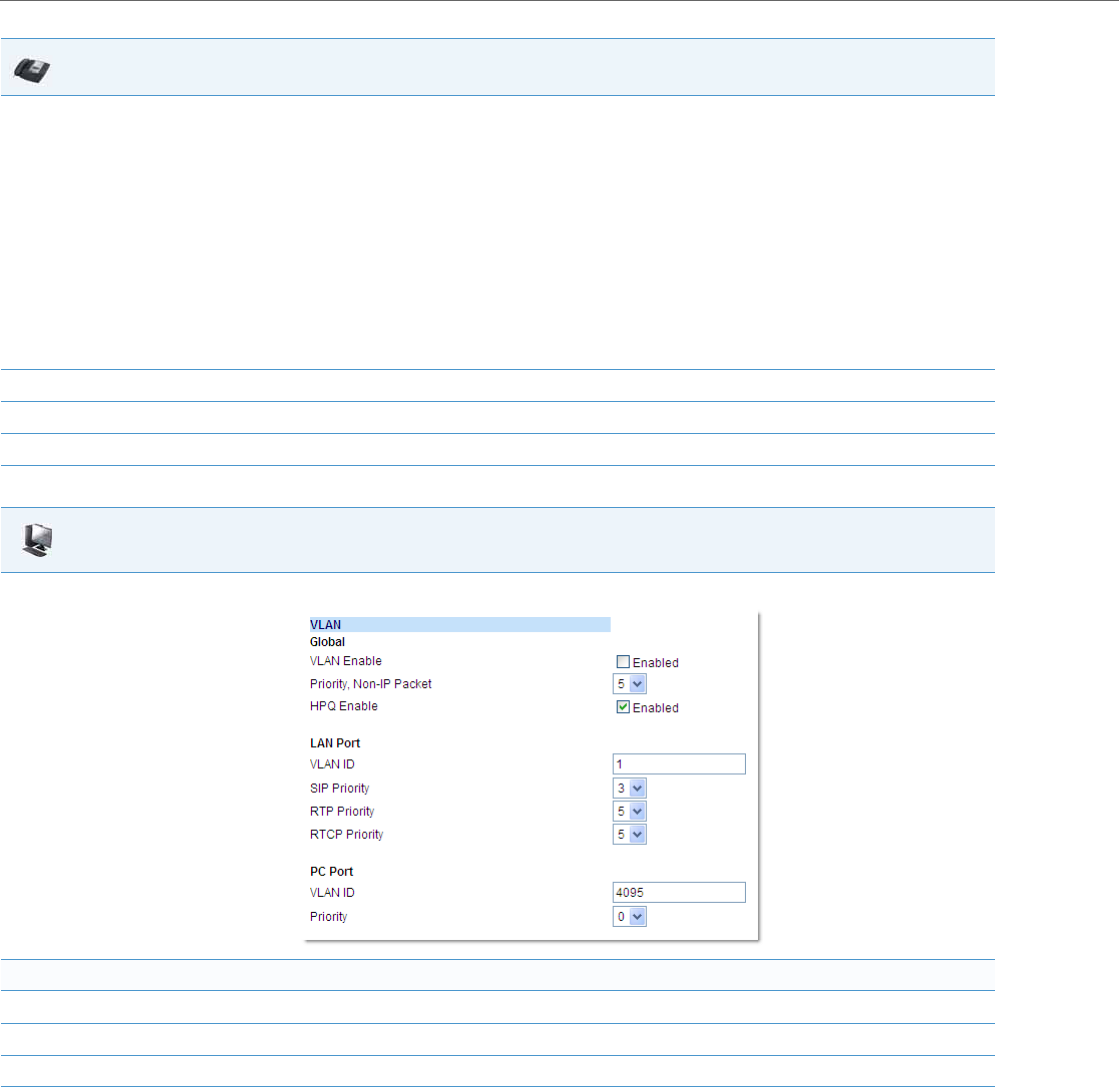
Network Settings
4-50 41-001343-02 REV04 – 05.2014
11. In the PC Port VLAN > PC Port VLAN ID field, enter a value from 1 to 4095 to specify the VLAN ID for the LAN Port. Default is 4095.
Note:
Setting the PC Port VLAN ID to 4095 and LAN Port VLAN ID to any ID from 1 to 4094 will allow frames from the LAN port (containing a VLAN
ID) to be untagged before being forwarded to the PC port and frames from the PC port (without a VLAN ID) to be tagged with the configured
VLAN ID before being forwarded to the LAN port.
Example:
You enable tagging on the phone port as normal but set the PC Port VLAN ID to 4095 and the LAN Port VLAN ID to any ID from 1 to 4094. The
following example sets the LAN port to be on VLAN 3 but the PC port is configured as untagged.
VLAN Settings->VLAN: Enable
VLAN Settings->LAN Port VLAN->LAN Port VLAN ID: 3
VLAN Settings->PC Port VLAN->PC Port VLAN ID: 4095
12. In the PC Port VLAN > Priority field, enter a value from 0 to 7 to specify the PC Port VLAN priority. Default is 0.
13. Press the Save softkey.
14. Restart the phone for the selection to take affect.
Aastra Web UI
1. Click on Advanced Settings->Network->VLAN.
To globally enable/disable VLAN and set priority for non-IP packets:
2. Enable VLAN by checking the VLAN Enable field check box. (Disable this field by unchecking the check box).
3. With VLAN enabled, select the priority (0 to 7) for non-IP packets in the Priority, Non-IP Packet field.
4. Enable or disable VLAN HPQ by checking or unchecking the HPQ Enable field check box.
IP Phone UI
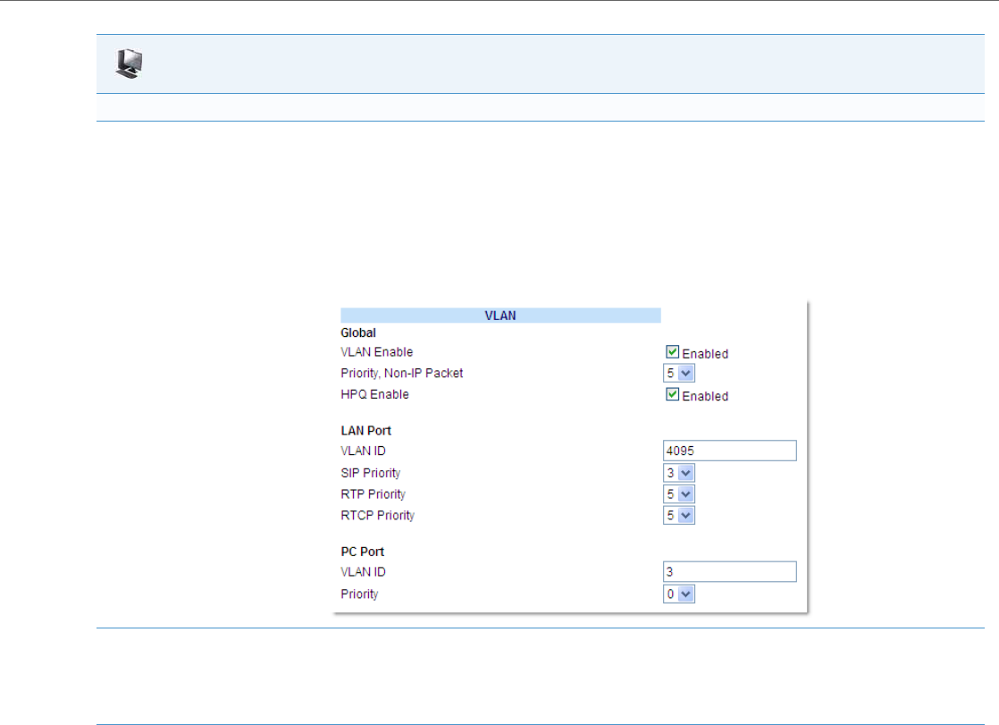
Network Settings
41-001343-02 REV04 – 05.2014 4-51
To set VLAN ID and priority for the LAN Port (Port 0):
5. Enter a VLAN ID value from 1 to 4095 in the VLAN ID field. Default is 1.
Note:
Setting the LAN Port VLAN ID to 4095 and PC Port VLAN ID to any ID from 1 to 4094 will allow frames from the PC port (containing a VLAN
ID) to be untagged before being forwarded to the LAN port and frames from the LAN port (without a VLAN ID) to be tagged with the con-
figured VLAN ID before being forwarded to the PC port.
Example:
You enable tagging on the phone port as normal but set the LAN Port VLAN ID to 4095 and the PC Port VLAN ID to any ID from 1 to 4094. The
following example sets the PC port to be on VLAN 3 but the LAN port is configured as untagged.
6. Choose a VLAN Protocol (SIP Priority, RTP Priority, and/or RTCP Priority), and select a priority for the associated Protocol. Valid values are
0 to 7, Defaults are as follows:
•SIP Priority = 3
•RTP Priority = 5
•RTCP Priority = 5
Aastra Web UI
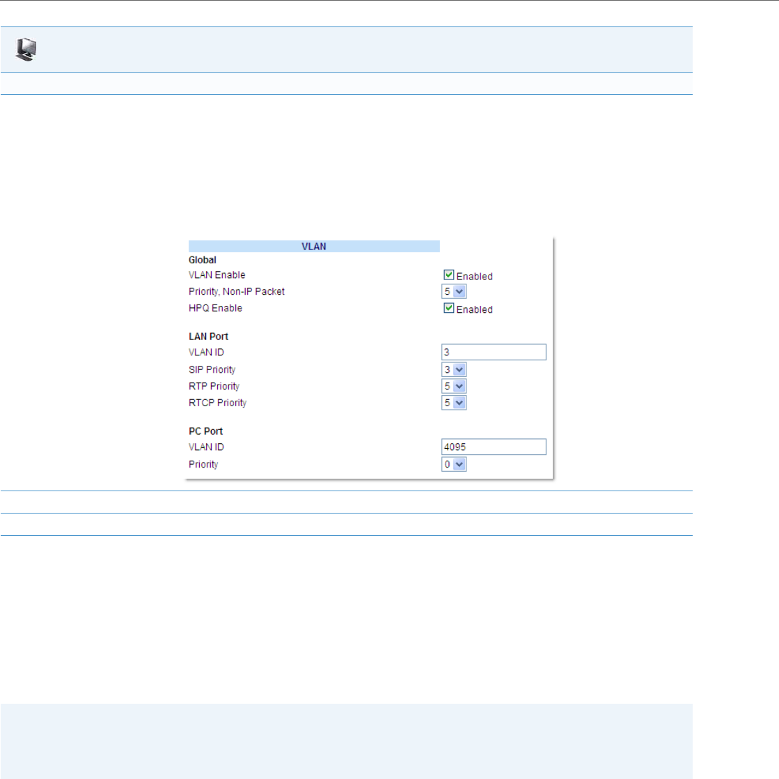
Network Settings
4-52 41-001343-02 REV04 – 05.2014
RPORT
The Session Initiation Protocol (SIP) operates over UDP and TCP. When used with UDP, responses to requests are returned
to the source address from which the request came, and returned to the port written into the topmost “Via” header of
the request. However, this behavior is not desirable when the client is behind a Network Address Translation (NAT) or
firewall.
A parameter created for the “Via” header called “Rport” in RFC 3581, allows a client to request that the server send the
response back to the source IP address and the port from which the request came.
When you enable “Rport, the phone always uses symmetric signaling (listens on the port used for sending requests.)
An Administrator can configure “Rport” using the configuration files or the Aastra Web UI.
To set VLAN ID and priority for the PC Port (Port 1):
7. Enter a VLAN ID value from 1 to 4095 in the VLAN ID field. Default is 4095.
Note:
Setting the PC Port VLAN ID to 4095 and LAN Port VLAN ID to any ID from 1 to 4094 will allow frames from the LAN port (containing a VLAN
ID) to be untagged before being forwarded to the PC port and frames from the PC port (without a VLAN ID) to be tagged with the configured
VLAN ID before being forwarded to the LAN port.
Example:
You enable tagging on the phone port as normal but set the PC Port VLAN ID to 4095 and the LAN Port VLAN ID to any ID from 1 to 4094. The
following example sets the LAN port to be on VLAN 3 but the PC port is configured as untagged.
8. Select a VLAN priority value from 0 to 7 for the PC Port in the Priority field. Default is 0.
9. Click Save Settings to save your settings.
Note:
Configuring the Rport parameter is recommended for clients behind a Network Address Translation (NAT) or firewall
since this parameter allows a client to request that the server send the response back to the source IP address and the
port from which the request came.
Aastra Web UI
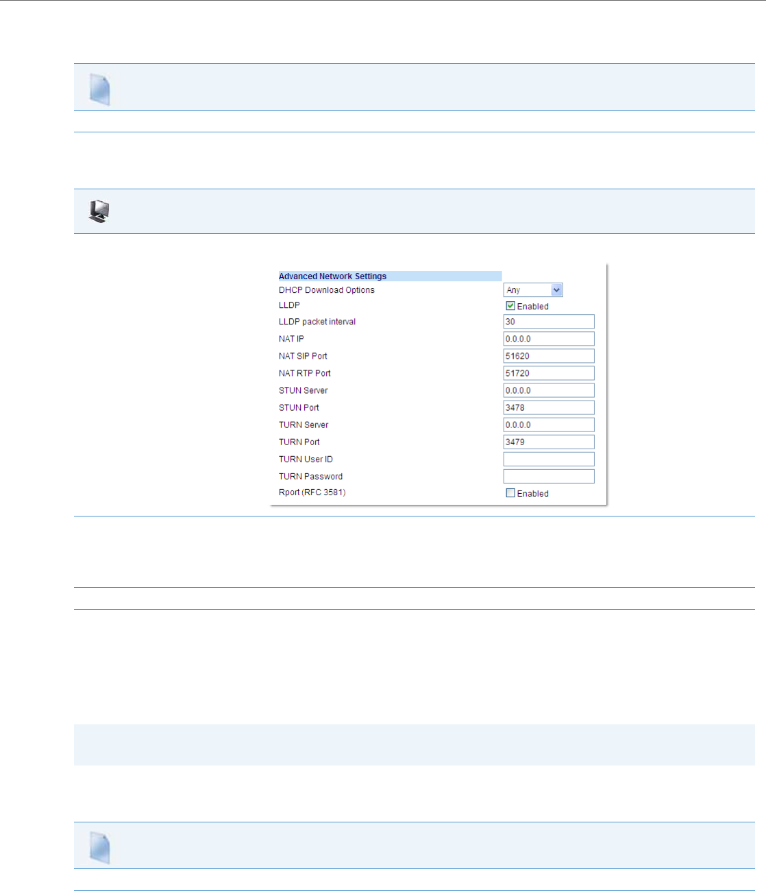
Network Settings
41-001343-02 REV04 – 05.2014 4-53
Configuring Rport Using the Configuration Files
Use the following procedures to configure Rport on your phone.
Configuring Rport Using the Aastra Web UI
Use the following procedure to configure Rport on your phone using the Aastra Web UI.
Network Time Servers
Network Time Protocol (NTP) is a protocol that the IP phone uses to synchronize the phone clock time with a computer
(configuration server) in the network.
To use NTP, you must enable it using the configuration files or the Aastra Web UI. You can specify up to three time servers
in your network.
Configuring NTP Servers (optional)
Use the following procedure to enable/disable and configure the NTP servers using the configuration files.
Configuration Files
For specific parameters you can set in the configuration files, see Appendix A, the section, “Rport Setting” on pageA-26.
Aastra Web UI
1. Click on Advanced Settings->Network->Advanced Network Settings.
2. In the "Advanced Network Settings" section, enable the "Rport (RFC3581" field by checking the check box. (Disable Rport by unchecking
the box).
“Rport” in RFC 3581, allows a client to request that the server send the response back to the source IP address and the port from which the
request came.
3. Click Save Settings to save your changes.
Note:
The IP phones support NTP version 1.
Configuration Files
For specific parameters you can set in the configuration files, see Appendix A, the section, “Time Server Settings” on pageA-45.
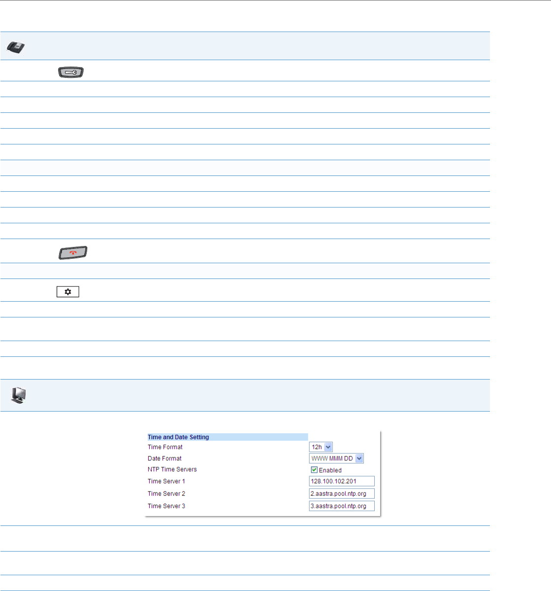
Network Settings
4-54 41-001343-02 REV04 – 05.2014
Use the following procedure to enable/disable the NTP server using the IP Phone UI.
Use the following procedure to enable/disable and configure the NTP Servers using the Aastra Web UI.
IP Phone UI
1. Press on the phone to enter the Options List.
2. Select Preferences.
3. Select Time and Date.
4. Select Timer Server 1, Timer Server 2, or Time Server 3.
5. Enter the IP Address (in dotted decimal) or qualified domain name for the Time Server.
6. Press Done to save the change.
For the 6739i:
1. Press the Options key on the phone to enter the Options List.
1. Press Set Time.
2. Press Timer Server 1, Time Server 2, or Time Server 3.
3. Enter the IP Address (in dotted decimal) or qualified domain name for the Time Server.
4. Press to return to the idle screen.
For the 6867i:
1. Press on the phone to enter the Options List.
2. Select Time and Date > Set Date and Time.
3. In the Timer Server 1, Time Server 2, and/or Time Server 3 fields, enter the respective IP address (in dotted decimal) or qualified domain
name.
4. Press the Save softkey.
Aastra Web UI
1. Click on Basic Settings->Preferences->Time and Date Setting.
2. Enable the "NTP Time Servers" field by checking the check box.
(Disable this field by unchecking the box). Default is disabled.
3. Enter an IP address or qualified domain name in the "Time Server 1", "Time Server 2", and/or "Time Server 3" field(s) to specify the location
of the NTP time server.
4. Click Save Settings to save your changes.

Global SIP Settings
41-001343-02 REV04 – 05.2014 4-55
Global SIP Settings
Description
The IP phone uses the information in the Global Session Initiation Protocol (SIP) settings to register at the IP PBX.
The IP phone configuration defines network and user account parameters that apply globally to all SIP lines. Since not all
SIP lines are necessarily hosted using the same IP-PBX/server or user account, additional sets of per-line parameters can
also be defined for network and user account.
You configure and modify these parameters and associated values using the configuration files, the IP phone UI, or the
Aastra Web UI. The Aastra Web UI and configuration file methods configure global and per-line SIP settings on the IP
phone. The IP phone UI configures global SIP settings only.
On the IP Phones, you can configure Basic and Advanced SIP Settings. The Basic SIP Settings include authentication and
network settings. The Advanced SIP Settings include other features you can configure on the IP Phone.
Reference
For more information about Basic SIP Settings (for authentication and network), see “Basic SIP Settings” on page4-55.
For more information about Advanced SIP Settings, see “Advanced SIP Settings (optional)” on page4-69.
Basic SIP Settings
Specific parameters are configurable on a global and per-line basis. You can also configure specific parameters using the IP
Phone UI, the Aastra Web UI, or the configuration files. If you have a proxy server or have a SIP registrar present at a differ-
ent location than the PBX server, the SIP parameters may need to be changed.
The IP phones allow you to define different SIP lines with the same account information (i.e., same user name) but with dif-
ferent registrar and proxy IP addresses. This feature works with Registration, Subscription, and Notify processing. This fea-
ture also works with the following types of calls: incoming, outgoing, Broadsoft Shared Call Appearance (SCA), Bridged
Line Appearance (BLA), conference, transfer, blind transfer.
The following tables identify the SIP global and per-line, authentication and network parameters on the IP phones.

Global SIP Settings
4-56 41-001343-02 REV04 – 05.2014
SIP Global Parameters
Reference
For more information about centralized conferencing, see Chapter 5, the section, “Centralized Conferencing (for Sylantro
and Broadsoft Servers)” on page5-266.
IP Phone UI Parameters Aastra Web UI Parameters Configuration File Parameters
SIP Global Authentication Parameters
•Screen Name
•User Name
•Display Name
•Authentication Name
•Password
•Screen Name
•Screen Name 2
•Phone Number
•Caller ID
•Authentication Name
•Password
•BLA Number
•Line Mode
•Call Waiting (see Chapter 5, “Configuring
Operational Features”)
•sip screen name
•sip screen name 2
•sip user name
•sip display name
•sip auth name
•sip password
•sip bla number
•sip mode
•call waiting (see Chapter 5, “Configuring Opera-
tional Features”
•sip vmail
SIP Global Network Parameters
•Proxy Server
•Proxy Port
•Registrar Server
•Registrar Port
•Proxy Server
•Proxy Port
•Backup Proxy Server
•Backup Proxy Port
•Outbound Proxy Server
•Outbound Proxy Port
•Backup Outbound Proxy
•Backup Outbound Proxy Port
•Registrar Server
•Registrar Port
•Backup Registrar Server
•Backup Registrar Port
•Registration Period
•Conference Server URI (see Chapter 5, “Con-
figuring Operational Features”)
•sip proxy ip
•sip proxy port
•sip backup proxy ip
•sip backup proxy port
•sip outbound proxy
•sip outbound proxy port
•sip backup outbound proxy
•sip backup outbound proxy port
•sip registrar ip
•sip registrar port
•sip backup registrar ip
•sip backup registrar port
•sip registration period
•sip centralized conf (see Chapter 5, “Configuring
Operational Features”)

Global SIP Settings
41-001343-02 REV04 – 05.2014 4-57
SIP Per-Line Parameters
Reference
For more information about centralized conferencing, see Chapter 5, the section, “Centralized Conferencing (for Sylantro
and Broadsoft Servers)” on page5-266.
Specific sets of SIP parameters are inter-dependent with each other. To prevent conflicting parameter values from being
applied, per-line values always take precedence over the corresponding set of global values.
For example, if a parameter value is configured for one of the per-line sets, all parameters from that set are applied and all
parameters from the corresponding global section are ignored, even if some of the parameters within the global set are
not defined in the per-line set.
IP Phone UI Parameters Aastra Web UI Parameters Configuration File Parameters
SIP Per-Line Authentication Parameters
•Screen Name
•User Name
•Display Name
•Auth Name
•Password
•Screen Name
•Screen Name 2
•Phone Number
•Caller ID
•Authentication Name
•Password
•BLA Number
•Line Mode
•Call Waiting (see Chapter 5, “Configuring
Operational Features”
•sip lineN screen name
•sip lineN screen name 2
•sip lineN user name
•sip lineN display name
•sip lineN auth name
•sip lineN password
•sip lineN bla number
•sip lineN mode
•sip lineN call waiting
(see Chapter 5, “Configuring Operational Fea-
tures”
•sip lineN vmail
SIP Per-Line Network Parameters
•Proxy Server
•Proxy Port
•Registrar Server
•Registrar Port
•Proxy Server
•Proxy Port
•Backup Proxy Server
•Backup Proxy Port
•Outbound Proxy Server
•Outbound Proxy Port
•Backup Outbound Proxy Server
•Backup Outbound Proxy Port
•Registrar Server
•Registrar Port
•Backup Registrar Server
•Backup Registrar Port
•Registration Period
•Conference Server URI (see Chapter 5, “Con-
figuring Operational Features”)
•sip lineN proxy ip
•sip lineN proxy port
•sip lineN backup proxy ip
•sip lineN backup proxy port
•sip lineN outbound proxy
•sip lineN outbound proxy port
•sip lineN backup outbound proxy
•sip lineN backup outbound proxy port
•sip lineN registrar ip
•sip lineN registrar port
•sip lineN backup registrar ip
•sip lineN backup registrar port
•sip lineN registration period
•sip lineN centralized conf (see Chapter 5, “Config-
uring Operational Features”)
Note:
The "sip vmail" and "sip lineN vmail" parameters are configurable using the configuration files only. To configure
voicemail see Chapter 5, the section, “Voicemail” on page5-235.

Global SIP Settings
4-58 41-001343-02 REV04 – 05.2014
SIP Password Masking
The “mask sip password” configuration parameter can be used to mask a user’s SIP account password in the server.cfg
and local.cfg files (downloaded from the IP phone’s Web UI troubleshooting page for debug purposes). The parameter is
disabled by default.
Configuring SIP Password Masking
Use the following procedure to configure SIP password masking using the configuration files.
SIP Precedence Example
The following example shows the SIP proxy feature and example schema for storage and parsing of the SIP configuration
parameters.
The following SIP configuration is assumed:
# SIP network block
sip proxy ip: 10.30.11.154
sip proxy port: 5060
sip registrar ip: 10.44.122.37
sip registrar port: 4020
sip line3 proxy ip: siparator.vonage.com
sip line3 proxy port: 0
Line3 specifies per-line values for proxy IP address and proxy port, so the phone uses those parameter values for SIP calls
made on that line. However, because those parameters are part of the SIP network block, the phone does not apply any
of the global SIP network block parameters. So even though the global parameters configure a SIP registrar, Line3 on the
phone ignores all global network block parameters. Since line3 does not contain a per-line SIP registrar entry, the phone
does not use a registrar for that line.
Backup Proxy/Registrar Support
The IP phones support a backup SIP proxy and backup SIP registrar feature. If the primary server is unavailable, the
phone automatically switches to the backup server allowing the user's phone to remain in service.
How it Works
All SIP registration messages are sent to the primary registrar first. If the server is unavailable, then a new registration
request is sent to the backup registrar. This also applies to registration renewal messages, which try the primary server
before the backup.
Similarly, any outgoing calls attempt to use the primary proxy first, then the backup if necessary. In addition, subscrip-
tions for BLF, BLA, and explicit MWI can also use the backup proxy when the primary fails. Outgoing calls and the previ-
ously mentioned subscriptions behave the same as registrations, where the primary proxy is tried before the backup.
You can configure the backup SIP proxy on a global or per-line basis via the configuration files or the Aastra Web UI.
Configuration Files
For specific parameters you can set in the configuration files, see Appendix A, the section, “SIP Basic, Global Settings” on pageA-61.
Note:
Global SIP parameters apply to all lines unless overridden by a per-line configuration. Per-line settings are configurable
for lines 1 through 7.

Global SIP Settings
41-001343-02 REV04 – 05.2014 4-59
SIP Outbound Support
The IP Phones support draft-ietf-sip-outbound-15. That specification describes how a SIP User Agent (UA) behind a fire-
wall, reuses an existing connection (usually the REGISTER outbound connection) for the inbound request if the proxy sup-
ports it. The UA uses keep-alive packets to monitor the connection status.
An Administrator can enable or disable this feature using the following parameter in the configuration files:
•sip outbound support
Enabling/Disabling SIP Outbound Draft 15 Support
Use the following procedure to enable/disable SIP outbound Draft 15 support.
Backup Outbound Proxy and Failover Support
The IP phones support a backup outbound proxy and failover. This feature provides the following:
•The ability to specify a backup outbound proxy.
•The ability to support SIP outbound on all connection types.
•The ability to configure the SIP outbound keep alive timer.
•The ability to reestablish failed outbound connections in the background.
•The ability to support the DNS Cache Time-to-Live (TTL) requirements
Using this feature depends on the SIP network settings on your phone. The following table identifies network configura-
tion scenarios, and the method by which this specific feature works in each scenario.
Note:
If the Global SIP parameter “Persistent TLS” is set on the phone, then only one TLS persistent connection can be estab-
lished since the phone uses the local port 5061 for connection. If the Global SIP parameter “TLS” is set on the phone,
more than one connection can be setup since the phone uses a random local port for connection.
Configuration Files
For the specific parameter you can set in the configuration files, see Appendix A, the section, “SIP Outbound Support” on pageA-60.
IF THEN
SIP Outbound Disabled and
backup proxy and backup registrar
configured, •All invite, register, and subscribe requests attempt to use the primary proxy/registrar
first
•If the primary registrar fails, the phone registers to the backup proxy.
•If the backup proxy fails, the phone registers using the Address of Record (AOR) of the
backup proxy, and moves all subscriptions to the backup proxy.
•When the primary registrar comes back online, the phone registers to it using the cur-
rently active AOR.
•When the primary proxy comes back online the phone registers with the primary AOR
to the currently active registrar and moves all subscriptions to the primary proxy.
backup proxy, backup registrar, and backup outbound
proxy configured, • All invite, register, and subscribe requests attempt to use the primary proxy/registrar
first.
•If any connection fails, the phone registers the backup AOR on the backup registrar. It
moves all subscriptions to the backup proxy.
•When the primary is functional again, registration and subscriptions are moved back to
the primary proxy/registrar.
backup outbound proxy configured only, • All invite, register and subscribe requests are sent through the primary outbound
proxy first.
•If the primary proxy fails, the phone performs registration and subscriptions through
the backup outbound proxy.
•When the primary proxy comes back online, the registrations and subscriptions are
performed again through the primary outbound proxy.

Global SIP Settings
4-60 41-001343-02 REV04 – 05.2014
Configuring a Backup Outbound Proxy
To configure this feature an Administrator can set the following parameters in the configuration files or the Aastra Web
UI:
SIP Outbound Enabled and
backup proxy and backup registrar configured, •Establishes flow to the primary proxy and registrar.
•If the flow to the primary registrar fails, the phone:
–establishes flow to the backup registrar.
–registers to the backup registrar.
–attempts to reestablish flow to the primary registrar in the background.
–When the primary registrar comes back up, the phone unregisters from the backup
and registers with the primary.
•If the flow to the primary proxy fails, the phone:
–establishes flow to the backup proxy.
–registers the new AOR with the active registrar.
–moves subscriptions to the backup proxy.
–attempts to reestablish the flow to the primary proxy in the background.
•When the flow to the primary proxy is reestablished, the phone:
–registers the primary AOR to the active registrar.
–moves subscriptions to the primary proxy.
–unregisters/unsubscribes from the backup proxy/registrar.
backup proxy, backup registrar, and backup outbound
proxy configured,
Note:
This configuration assumes that the outbound proxy is
maintaining its own outbound connections to the
proxy/registrar.
•Establishes a flow to the primary outbound proxy.
•If the flow fails, the phone:
–establishes the flow to the backup proxy.
–registers the backup AOR to the backup registrar.
–moves subscriptions to the backup proxy.
–attempts to reestablish connection to the primary outbound proxy in the back-
ground.
•When the flow to the primary proxy is reestablished, the phone:
–registers the primary AOR to the primary registrar.
–moves the subscriptions to the primary proxy.
–unregisters/unsubscribes from the backup proxy/registrar.
backup outbound proxy configured only, •Establishes a flow to the primary outbound proxy.
•If the flow fails, the phone:
–establishes the flow to the backup proxy.
–registers the backup AOR to the backup registrar.
–moves subscriptions to the backup proxy.
Parameter Aastra Web UI Configuration Configuration File Configuration
sip outbound support - ✔
sip symmetric udp signaling - ✔
sip transport protocol ✔✔
Global Parameters
sip backup outbound proxy ✔✔
sip backup outbound proxy port ✔✔
Per-Line Parameters
sip lineN backup outbound proxy ✔✔
sip lineN backup outbound proxy port ✔✔
Note:
The “sip outbound support”, “sip symmetric udp signaling”, a n d “sip transport protocol” parameters are existing
parameters on the phone. For more information about these parameters, see Appendix A “SIP Outbound Support”,
“Symmetric UDP Signaling Setting”, and “Advanced SIP Settings”.

Global SIP Settings
41-001343-02 REV04 – 05.2014 4-61
Use the following procedure to configure backup outbound proxies.
Limitations
The following are limitations with this feature:
•Keep-alive mechanisms shall be limited to IPv4 only.
•Per M5T, RFC5686 is not fully supported although the draft upon which it was based (draft-ietf-sip-outbound-15) is sup-
ported.
SIP Server (SRV) Lookup
The SIP SRV Lookup feature allows you to configure the IP phone to issue a DNS query to retrieve records pertaining to a
SIP proxy, a SIP registrar, or a SIP outbound proxy.
The IP phone issues a DNS query for an SRV record when the IP address of the server is FQDN and the corresponding port
is 0.
For example, if the phone is configured with sip proxy ip of "ana.aastra.com", and sip proxy port of "0", the SRV lookup
may return multiple servers, based on the priorities if one is selected as primary and others are selected as secondary.
However, if the IP address is an FQDN and the corresponding server port is non-zero, then the phone issues a DNS "A"
Name Query to resolve the FQDN into dot notation form.
If the IP address is a valid dot notation and the port is zero, then a default port 5060 is used.
You can configure SRV lookup using the configuration files (aastra.cfg and <mac>.cfg) only. The parameters to use are:
•sip proxy ip
•sip proxy port
Contact Header Matching
When sending SIP packets, the IP Phones observe the Contact header by matching the username, domain name, port, and
transport as referenced in SIP RFC 3261.This is called “strict SIP Contact header matching.” However, in specific networks
(such as behind some SOHO routers), the phone registers with its private address in the Contact, but when the response is
sent back, the router maintains the public side IP address in the Contact header. This causes a non-matching Contact
header and the phone does not accept the new registration expiry timer.
You can set the parameter, “sip contact matching”, which allows the Administrator to specify the method used by the
phone to match the Contact Header. Previously by default, when sending SIP packets, the IP phones observed the contact
header by doing a full URI matching of username, domain, phone IP and port name, and transport (value=’0’). Now the
default value for the “sip contact matching” parameter is to match the username only (value=’2’). This parameter is avail-
able via the configuration files only.
Enabling/Disabling the “Contact Header Matching” Feature
Use the following procedure to enable/disable the “Contact Header Matching” feature.
Configuration Files
For the specific parameter you can set in the configuration files, see Appendix A, the section, “Backup Outbound Proxy (Global Settings)” on pageA-
68 and “Backup Outbound Proxy (Per-line Settings)” on pageA-77.
Note:
The phones only generate a ‘request’ and do not facilitate the ‘DNS or SRV service or provide a response to the requests.
Configuration Files
For the specific parameter you can set in the configuration files, see Appendix A, the section, “Contact Header Matching” on pageA-60.

Global SIP Settings
4-62 41-001343-02 REV04 – 05.2014
Configuring Basic SIP Authentication Settings
You can configure SIP authentication settings using the configuration files, the IP Phone UI, or the Aastra Web UI.
Reference
For more information about setting the call waiting parameters, see Chapter 5, the section, “Call Waiting” on page5-57.
Call Waiting cannot be set via the IP Phone UI.
Note:
To configure the SIP settings per-line, use the configuration files or the Aastra Web UI.
Configuration Files
For specific parameters you can set in the configuration files, see Appendix A, the section, “SIP Basic, Global Settings” on pageA-61 or “SIP Basic, Per-
Line Settings” on pageA-69. For specific parameters you can set in the configuration files for call waiting, see the section, “Call Waiting Settings” on
pageA-64 or “SIP Per-Line Call Waiting Setting” on pageA-73.
Note:
You can set global configuration only using the IP Phone UI.
IP Phone UI
1. Press on the phone to enter the Options List.
2. Select Administrator Menu.
3. Enter your Administrator password.
The IP Phones accept numeric passwords only.
4. Select SIP Settings.
5. Select User Name to enter the username that appears in the name field of the SIP URI. This user name is also used for registering the phone
at the registrar.
Note:
The IP phones allow usernames containing dots (“.”). You can also enter the same user name for different registrar and proxy IP addresses.
6. Press Done to save the changes.
7. Select Display Name to enter the name used in the display name field of the "From SIP" header field.
8. Press Done to save the changes.
9. Select Screen Name and enter the name to display on the idle screen.
10. Press Done to save the changes.
11. Select Authentication Name to enter the authorization name used in the username field of the Authorization header field of the SIP REG-
ISTER request.
12. Press Done to save the changes.
13. Select Password to enter the password used to register the IP phone with the SIP proxy.
Note:
The IP phones accept numeric passwords only.
14. Press Done (3 times) to save the changes.
Note:
The session prompts you to restart the IP phone to apply the configuration settings
15. Select Restart.
Global SIP Settings
41-001343-02 REV04 – 05.2014 4-63
For the 6739i:
1. Press the Options key on the phone to enter the Options List.
2. Press Advanced. A keyboard displays.
3. Enter the Administrator password using the keyboard. Default is “22222”.
4. Press SIP.
5. Press User Name and enter the username that appears in the name field of the SIP URI. This user name is also used for registering the phone
at the registrar.
Note:
The IP phones allow usernames containing dots (“.”). You can also enter the same user name for different registrar and proxy IP addresses.
6. Press to scroll to the next screen.
7. Press Display Name and enter the name used in the display name field of the "From SIP" header.
8. Press Screen Name and enter the name to display on the idle screen.
9. Press Auth. Name and enter the authorization name used in the username field of the Authorization header field of the SIP REGISTER
request.
10. Press Password and enter the password used to register the IP phone with the SIP proxy.
Note:
The IP phones accept numeric passwords only.
11. Press until the Options List screen displays.
12. Press Restart to restart the phone for the change to take affect.
For the 6867i:
1. Press on the phone to enter the Options List.
2. Press the Advanced softkey.
3. Enter the Administrator password using the keypad. Default is “22222”.
4. Select SIP > User.
5. In the User Name field, enter the username that appears in the name field of the SIP URI. This user name is also used for registering the
phone at the registrar.
Note:
The IP phones allow usernames containing dots (“.”). You can also enter the same user name for different registrar and proxy IP addresses.
6. In the Display Name field, enter the name used in the display name field of the "From SIP" header.
7. In the Screen Name field, enter the name to display on the idle screen.
8. In the Auth. Name field, enter the authorization name used in the username field of the Authorization header field of the SIP REGISTER
request.
9. In the Password field, enter the password used to register the IP phone with the SIP proxy.
Note:
The IP phones accept numeric passwords only.
10. Press the Save softkey.
11. Restart the phone for the changes to take affect.
IP Phone UI
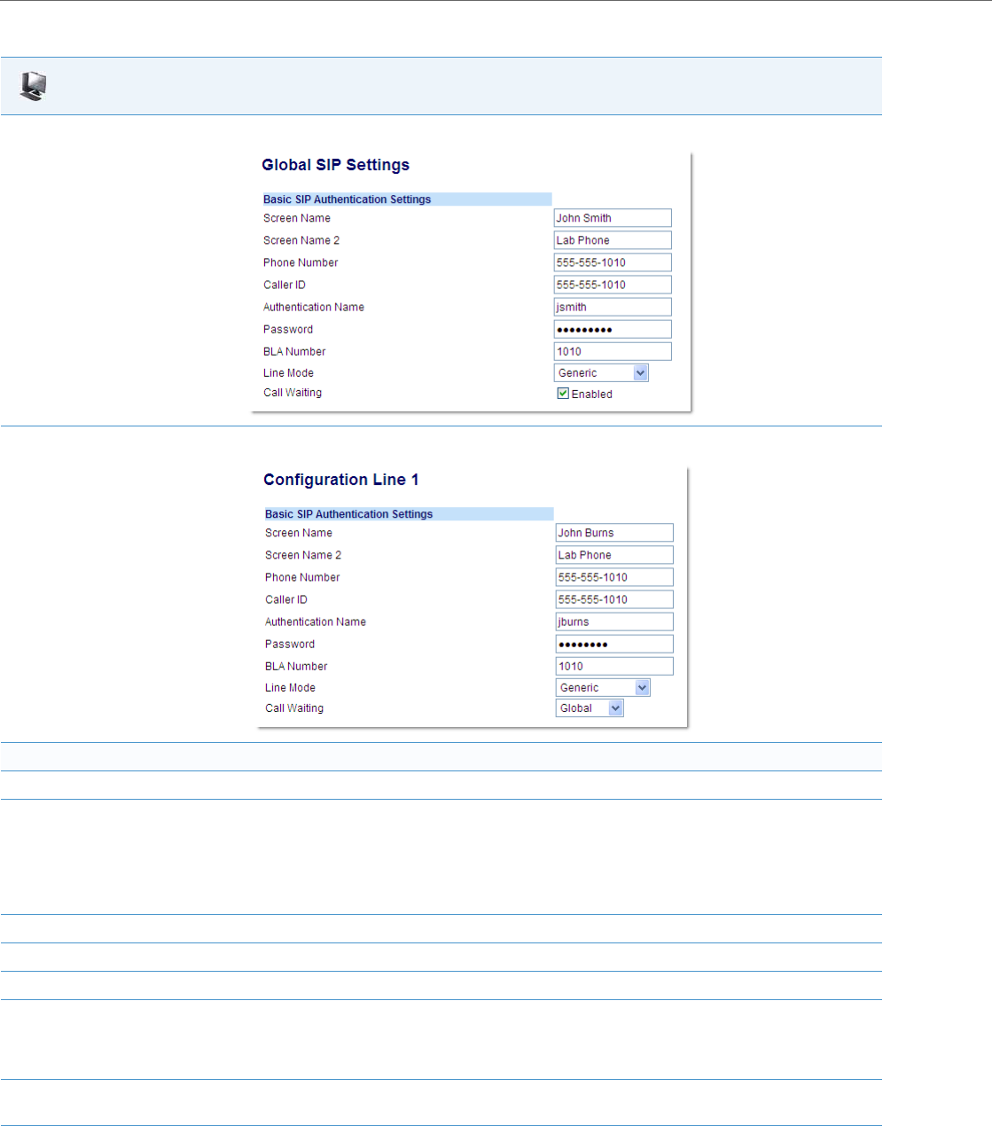
Global SIP Settings
4-64 41-001343-02 REV04 – 05.2014
Aastra Web UI
1. For global configuration, click on Advanced Settings->Global SIP->Basic SIP Authentication Settings.
Or, for per-line configuration, click on Advanced Settings->Line N (1-9)->Basic SIP Authentication Settings.
Configure SIP authentication settings:
2. In the "Screen Name" field, enter the screen name that displays on the idle screen.
3. In the "Screen Name 2" field, enter the text you want to display on the phone under the “Screen Name” on the idle screen.
Notes:
•If other status messages display on the phone, such as “Network Disconnected”, the Screen Name 2 value does not display.
•Symbol characters are allowed (such as “#”).
•If the text is longer than the display width, than the display truncates the text to fit the display.
4. In the "Phone Number" field, enter the phone number of the IP phone.
5. In the "Caller ID" field, enter the phone number of the IP phone.
6. In the "Authentication Name" field, enter the name used in the username field of the Authorization header of the SIP REGISTER request.
7. In the "Password" field, enter the password used to register the IP phone with the SIP proxy.
Note:
The IP phones accept numeric passwords only.
8. In the "BLA Number" field, enter the Bridge Line Appearance (BLA) number to be shared across all IP phones.
For more information about setting the BLA on the phone, see Chapter 5, the section, “Bridged Line Appearance (BLA)” on page5-166.
9. In the "Line Mode" field, select "Generic" for normal mode, "BroadSoft SCA" for a BroadWorks network.

Global SIP Settings
41-001343-02 REV04 – 05.2014 4-65
Configuring Basic SIP Network Settings (optional)
You can configure SIP network settings using the configuration files, the IP Phone UI, or the Aastra Web UI.
Configure Global Call Waiting
10. The "Call Waiting" field is enabled by default. To disable call waiting on a global basis, uncheck this box.
For more information about setting the call waiting parameters, see Chapter 5, the section, “Call Waiting” on page5-57.
Configure Per-Line Call Waiting
11. The "Call Waiting" field is set to “Global” by default. To enable call waiting for a specific line, select “enabled” from the list in this field. To dis-
able call waiting for a specific line, select “disabled” from the list in this field.
For more information about setting the call waiting parameters, see Chapter 5, the section, “Call Waiting” on page5-57.
12. Click Save Settings to save your changes.
Note:
To configure the SIP settings per-line, use the configuration files or the Aastra Web UI.
Configuration Files
For specific parameters you can set in the configuration files, see Appendix A, the section, “SIP Basic, Global Settings” on pageA-61 or “SIP Basic, Per-
Line Settings” on pageA-69.
Note:
You can set global configuration only using the IP Phone UI.
IP Phone UI
1. Press on the phone to enter the Options List.
2. Select Administrator Menu.
3. Enter your Administrator password.
Note:
The IP Phones accept numeric passwords only.
4. Select SIP Settings.
Configuring Proxy IP and Proxy Port
5. Select Proxy IP/Port.
6. Enter an IP address or fully qualified host name in the Proxy Server field. Default is 0.0.0.0.
7. Enter a Proxy Port number in the Proxy Port field for accessing the SIP proxy server.
Default is 0.
8. Press Done to save the changes.
Configuring Registrar IP and Registrar Port
9. Select Registrar IP/Port.
Aastra Web UI

Global SIP Settings
4-66 41-001343-02 REV04 – 05.2014
For the 6739i:
10. Enter an IP address or fully qualified host name in the Registrar Server field. Default is 0.0.0.0.
A global value of 0.0.0.0 disables registration. However, the phone is still active and you can dial using username@ip address of the phone.
If the Registrar IP address is set to 0.0.0.0 for a per-line basis (i.e., line 1, line 2, etc.), then the register request is not sent, the "No Service" mes-
sage does not display, and the message waiting indicator (MWI) does not come on.
11. Enter a Registrar Port number in the Registrar Port field for accessing the SIP registrar server.
Default is 0.
12. Press Done to save the changes.
Enabling/Disabling the Use of the Registrar Server
13. Select SIP Register.
14. Press Change to set Register to "Yes " (enable) or "No" (disable). Default is “Ye s”.
This parameter enables/disables the IP phone to register on the network.
15. Press Done to save the changes.
Note:
The session prompts you to restart the IP phone to apply the configuration settings.
16. Select Restart.
Note:
You can set global configuration only using the IP Phone UI.
IP Phone UI
1. Press the Options key on the phone to enter the Options List.
2. Press the Advanced button. A keyboard displays.
3. Enter the Administrator password using the keyboard. Default is “22222”.
4. Press the SIP button.
Configuring Proxy IP and Proxy Port
5. Press Proxy Server and enter an IP address or fully qualified host name in the Proxy Server field. Default is 0.0.0.0.
6. Press Proxy Port and enter a Proxy Port number in the Proxy Port field for accessing the SIP proxy server. For example, 5060. Default is 0.
Configuring Registrar IP and Registrar Port
7. Press Registrar Server and enter an IP address or fully qualified host name in the Registrar Server field. Default is 0.0.0.0.
A global value of 0.0.0.0 disables registration. However, the phone is still active and you can dial using username@ip address of the phone.
If the Registrar IP address is set to 0.0.0.0 for a per-line basis (i.e, line 1, line 2, etc.), then the register request is not sent, the "No Service" mes-
sage does not display, and the message waiting indicator (MWI) does not come on.
8. Press Registrar Port and enter a Registrar Port number in the Registrar Port field for accessing the SIP registrar server. For example, 5060.
Default is 0.
9. Press until the Options List screen displays.
10. Press Restart to restart the phone for the change to take affect.
IP Phone UI
Global SIP Settings
41-001343-02 REV04 – 05.2014 4-67
For the 6867i:
Note:
You can set global configuration only using the IP Phone UI.
IP Phone UI
1. Press on the phone to enter the Options List.
2. Press the Advanced softkey.
3. Enter the Administrator password using the keypad. Default is “22222”.
4. Select SIP > Call Server.
Configuring Proxy IP and Proxy Port
5. In the Proxy Server field, enter an IP address or fully qualified host name in the Proxy Server field. Default is 0.0.0.0.
6. In the Proxy Port field, enter a Proxy Port number in the Proxy Port field for accessing the SIP proxy server. For example, 5060. Default is 0.
Configuring Registrar IP and Registrar Port
7. In the Registrar Server, enter an IP address or fully qualified host name in the Registrar Server field. Default is 0.0.0.0.
A global value of 0.0.0.0 disables registration. However, the phone is still active and you can dial using username@ip address of the phone.
If the Registrar IP address is set to 0.0.0.0 for a per-line basis (i.e, line 1, line 2, etc.), then the register request is not sent, the "No Service" mes-
sage does not display, and the message waiting indicator (MWI) does not come on.
8. In the Registrar Port field, enter a Registrar Port number in the Registrar Port field for accessing the SIP registrar server. For example, 5060.
Default is 0.
9. Press the Save softkey.
10. Restart the phone for the changes to take affect.
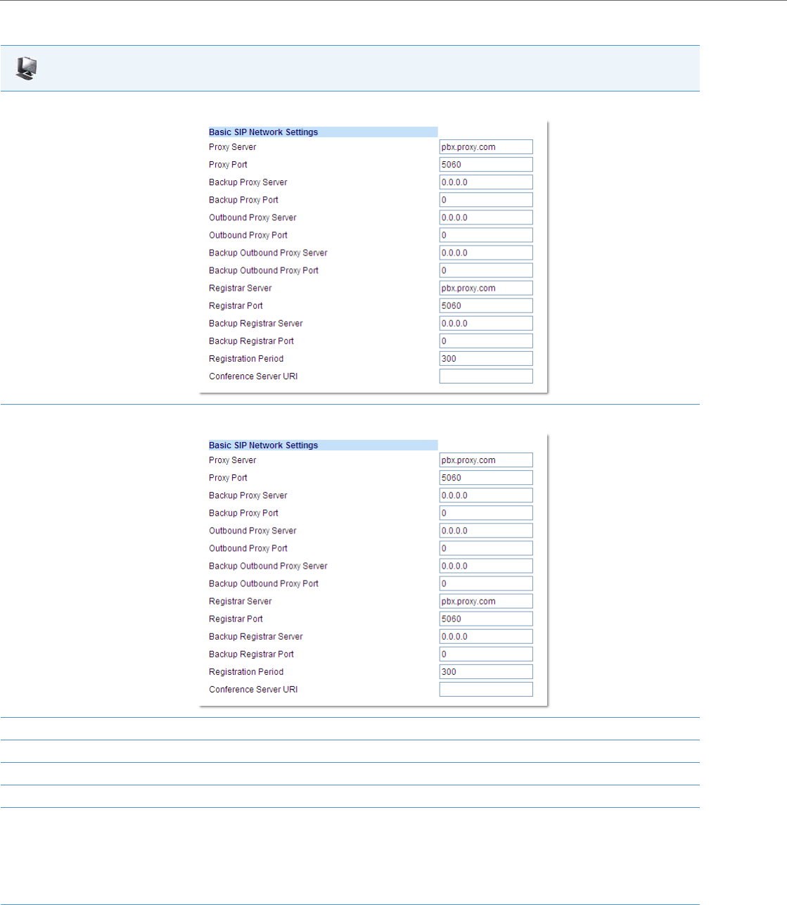
Global SIP Settings
4-68 41-001343-02 REV04 – 05.2014
Aastra Web UI
1. For global configuration, click on Advanced Settings->Global SIP->Basic SIP Network Settings.
Or, for per-line configuration, click on Advanced Settings->Line N (1-9)->Basic SIP Network Settings.
2. In the "Proxy Server" field, enter an IP address or fully qualified host name of the SIP proxy server.
3. In the "Proxy Port" field, enter a port number for accessing the SIP proxy server.
4. In the "Backup Proxy Server" field, enter an IP address or fully qualified host name for the backup proxy server.
5. In the "Backup Proxy Port" field, enter a port number for accessing the backup proxy server.
6. In the "Outbound Proxy Server" field, enter the SIP outbound proxy server IP address or fully qualified domain name. This parameter allows
all SIP messages originating from a line on the IP phone, to be sent to an outbound proxy server.
Note:
If you configure an outbound proxy and registrar for a specific line, and you also configure a global outbound proxy and registrar, the IP
phone uses the global configuration for all lines except
line 1. Line 1 uses the outbound proxy and registrar that you configured for that line.
7. In the "Outbound Proxy Port" field, enter the port on the IP phone that allows SIP messages to be sent to the outbound proxy server.

Global SIP Settings
41-001343-02 REV04 – 05.2014 4-69
Advanced SIP Settings (optional)
Advanced SIP Settings on the IP Phone allow you to configure specific features on the phone. The following table provides
a list of Advanced SIP Settings that you can configure using the Aastra Web UI or the configuration files.
8. In the "Backup Outbound Proxy Server" field, enter the backup SIP outbound proxy server IP address or fully qualified domain name.
9. In the "Backup Outbound Proxy Port" field, enter the port on the IP phone that allows SIP messages to be sent to the backup outbound
proxy server.
10. In the "Registrar Server" field, enter an IP address or fully qualified host name for the SIP registrar server. A global value of 0.0.0.0 disables
registration. However, the phone is still active and you can dial using username@ip address of the phone.
If the Registrar IP address is set to 0.0.0.0 for a per-line basis (i.e., line 1, line 2, etc.), then the register request is not sent, the "No Service" mes-
sage does not display, and the message waiting indicator (MWI) does not come on.
11. In the "Registrar Port" field, enter the port number associated with the Registrar.
12. In the "Backup Registrar Server" field, enter an IP address or fully qualified host name for the backup registrar server. A global value of
0.0.0.0 disables registration. However, the phone is still active and you can dial using username@ip address of the phone.
If the Backup Registrar IP address is set to 0.0.0.0 for a per-line basis (i.e., line 1, line 2, etc.), then the register request is not sent, the "No Serv-
ice" message does not display, and the message waiting indicator (MWI) does not come on.
13. In the "Backup Registrar Port" field, enter the port number associated with the backup registrar.
14. In the "Registration Period" field, enter the requested registration period, in seconds, from the registrar.
15. To enter a value in the “Conference Server URI” field, see Chapter 5, the section, “Centralized Conferencing (for Sylantro and Broadsoft Serv-
ers)” on page5-266.
16. Click Save Settings to save your changes.
Aastra Web UI Parameters Configuration File Parameters
Explicit MWI Subscription
Explicit MWI Subscription Period
sip explicit mwi subscription
sip explicit mwi subscription period
MWI for BLA Account sip mwi for bla account (see Chapter 5, “Configuring Operational Fea-
tures”)
Missed Call Summary Subscription (global)
Missed Call Summary Subscription (per-line)
(see Chapter 6, “Configuring Advanced Operational Features”)
Missed Call Summary Subscription Period
(see Chapter 6, “Configuring Advanced Operational Features”)
sip missed call summary subscription (global)
sip lineN missed call summary subscription (per-line) (see Chapter 6,
“Configuring Advanced Operational Features”)
sip missed call summary subscription period
(see Chapter 6, “Configuring Advanced Operational Features”)
AS-Feature-Event Subscription (global)
AS-Feature-Event Subscription (per-line)
(see Chapter 6, “Configuring Advanced Operational Features”)
AS-Feature Event Subscription Period (see Chapter 6, “Configuring
Advanced Operational Features”)
sip as-feature-event subscription (global)
sip lineN as-feature-event subscription (per-line)
(see Chapter 6, “Configuring Advanced Operational Features”)
sip as-feature-event subscription period
(see Chapter 6, “Configuring Advanced Operational Features”)
Send MAC Address in REGISTER Message
(see Chapter 6, “Configuring Advanced Operational Features”)
Send Line Number in REGISTER Message
(see Chapter 6, “Configuring Advanced Operational Features”)
sip send mac (see Chapter 6, “Configuring Advanced Operational Fea-
tures”)
sip send line (see Chapter 6, “Configuring Advanced Operational Fea-
tures”)
Session Timer sip session timer
T1 Timer
T2 Timer
sip T1 timer
sip T2 timer
Transaction Timer sip transaction timer
Transport Protocol sip transport protocol
Aastra Web UI

Global SIP Settings
4-70 41-001343-02 REV04 – 05.2014
The “sip subscription timeout retry timer” and “sip subscription failed retry timer” are only configurable through
the configuration files. The “sip subscription timeout retry timer” parameter can be used to control how long the
phone delays then retries a subscription when a SUBSCRIBE request is responded with a 408 (timeout) or 503 (service
unavailable) error code. The “sip subscription failed retry timer” parameter can be used to control how long the phone
delays then retries a subscription when a SUBSCRIBE request is responded with error codes other than 408 or 503.
If any one of the above parameters are configured with a valid setting, the default retry times for all event packages will
be overwritten with the new setting. If the parameters are not configured or contains a invalid setting, the default retry
timers for all event packages will be retained. Both parameters are disabled by default.
Reference
Refer to Appendix A,“Advanced SIP Settings” on page A-82 for a description of each of the above parameters.
For more information about Blacklist Duration and Whitelist Proxy, see Chapter 6, “Configuring Advanced Operational
Features.”
Configuring Advanced SIP Settings
Use the following procedures to configure the advanced SIP settings on the IP phone.
Local SIP UDP/TCP Port (see page4-27) sip local port (see page4-27)
Local SIP TLS Port (see page4-27)sip local tls port (see page4-27)
Registration Failed Retry Timer
Registration Timeout Retry Timer
Registration Renewal Timer
sip registration retry timer
sip registration timeout retry timer
sip registration renewal timer
N/A
N/A
sip subscription timeout retry timer
sip subscription failed retry timer
BLF Subscription Period (see Chapter 5, “Configuring Operational Fea-
tures”)sip blf subscription period (see Chapter 5, “Configuring Operational Fea-
tures”)
ACD Subscription Period (see Chapter 5, “Configuring Operational Fea-
tures”)sip acd subscription period (see Chapter 5, “Configuring Operational Fea-
tures”)
BLA Subscription Period (see Chapter 5, “Configuring Operational Fea-
tures”)sip acd subscription period (see Chapter 5, “Configuring Operational Fea-
tures”)
Blacklist Duration (see Chapter 6, “Configuring Advanced Operational Fea-
tures”)sip blacklist duration (see Chapter 6, “Configuring Advanced Operational
Features”)
Whitelist Proxy (see Chapter 6, “Configuring Advanced Operational Fea-
tures”)sip whitelist (see Chapter 6, “Configuring Advanced Operational Fea-
tures”)
XML SIP Notify (see Chapter 6, “Configuring Advanced Operational Fea-
tures”)XML SIP Notify (see Chapter 6, “Configuring Advanced Operational Fea-
tures”)
Configuration Files
For specific parameters you can set in the configuration files, see Appendix A, the section, “Advanced SIP Settings” on pageA-82.
Aastra Web UI Parameters Configuration File Parameters
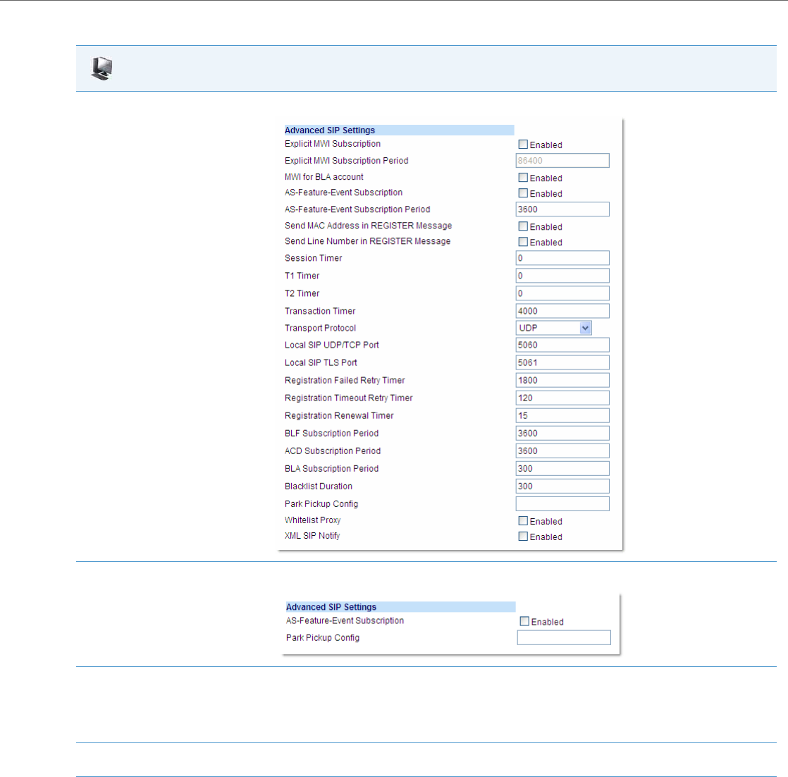
Global SIP Settings
41-001343-02 REV04 – 05.2014 4-71
Aastra Web UI
1. For Global configuration, click on Advanced Settings->Global SIP->Advanced SIP Settings.
2. Or for per-line configuration, click on Advanced Settings->Line N.
3. Enable the "Explicit MWI Subscription" field by checking the check box.
(Disable this field by unchecking the check box. Default is disabled).
If the IP phone has a message waiting subscription with the Service Provider, a Message Waiting Indicator (MWI) (LED or display icon) tells
the user there is a message on the IP Phone.
4. If you enable the “Explicit MWI Subscription” field, then in the “Explicit MWI Subscription Period” field, enter the requested duration, in
seconds, before the MWI subscription times out. The phone re-subscribes to MWI before the subscription period ends. Default is 86400.
5. Enable the “MWI for BLA Account” to enable or disable a BLA configured line to send an MWI SUBSCRIBE message for the BLA account.
Notes:
•If you change the setting on this parameter, you must reboot the phone for it to take affect.
•Both the “sip explicit mwi subscription” and “sip mwi for bla account” parameters must be enabled in order for the MWI subscription for
BLA to occur.
•The MWI re-subscription for the BLA account uses the value set for the "sip explicit mwi subscription period" parameter to re-subscribe.
•Whether or not the "sip mwi for bla account" parameter is enabled, the priority for displaying MWI does not change.

Global SIP Settings
4-72 41-001343-02 REV04 – 05.2014
6. Enable the “AS-Feature-Event Subscription” field by checking the check box.
(Disable this field by unchecking the check box. Default is disabled).
This feature enables or disables the specified line with the BroadSoft’s server-side DND, CFWD, or ACD features.
For more information about this feature, see Chapter 6, the section, “As-Feature-Event Subscription” on page6-11.
Note:
The “AS-Feature-Event Subscription” feature is configurable on a global or per-line basis.
7. If you enable the “AS-Feature-Event Subscription” field, then in the “AS-Feature-Event Subscription Period” field, enter the amount of
time, in seconds, between re-subscribing. If the phone does not re-subscribe in the time specified for this parameter, it loses subscription.
Default is 3600.
For more information about this feature, see Chapter 6, the section, “As-Feature-Event Subscription” on page6-11.
8. Enable the “Send MAC Address in REGISTER Message” and the “Send Line Number in REGISTER Message” fields by checking the check
boxes.
(Disable these fields by unchecking the check boxes. Default is disabled for both fields).
For more information about these message features, see Chapter 6, the section, “TR-069 Support” on page6-4.
Note:
The “AS-Feature-Event Subscription Period” feature is configurable on a global basis only
9. In the "Session Timer" field, enter the time, in seconds, that the IP phone uses to send periodic re-INVITE requests to keep a session alive. The
proxy uses these re-INVITE requests to maintain the status' of the connected sessions. See RFC4028 for details.
10. In the "Timer 1 and Timer 2" fields, enter a time, in milliseconds, that will apply to an IP phone session. These timers are SIP transaction layer
timers defined in RFC 3261.
Timer 1 is an estimate of the round-trip time (RTT). Default is 500 msec.
Timer 2 represents the amount of time a non-INVITE server transaction takes to respond to a request. Default is 4 seconds.
11. In the "Transaction Timer" field, enter the amount of time, in milliseconds, that the phone allows the call server (registrar/proxy) to respond
to SIP messages that it sends.
Valid values are 4000 to 64000. Default is 4000.
Note:
If the phone does not receive a response in the amount of time designated for this parameter, the phone assumes the message has timed
out.
12. In the "Transport Protocol" field, select a transport protocol to use when sending SIP Real-time Transport Protocol (RTP) packets. Valid val-
ues are User Datagram Protocol (UDP) and Transmission Control Protocol (TCP), UDP, TCP, Transport Layer Security (TLS) or Persistent TLS. The
value “UDP” is the default. For more information about TLS, see “RTP Encryption” on page4-79 and Chapter 6, the section, “Transport Layer
Security (TLS)” on page6-16.
13. In the "Local SIP UDP/TCP Port" field, specify the local source port (UDP/TCP) from which the phone receives SIP messages. Default is 5060.
For more information about this feature, see the section, “SIP and TLS Source Ports for NAT Traversal” on page4-27.
14. In the "Local SIP TLS Port" field, specify the local source port (SIPS/TLS) from which the phone sends SIP messages. Default is 5061.
For more information about this feature, see the section, “SIP and TLS Source Ports for NAT Traversal” on page4-27.
15. In the "Registration Failed Retry Timer" field, enter the amount of time, in seconds, that the phone waits between registration attempts
when a registration is rejected by the registrar.
Valid values are 30 to 1800. Default is 1800.
16. In the "Registration Timeout Retry Timer" field, enter the amount of time, in seconds, that the phone waits until it re-attempts to register
after a REGISTER message times out.
Valid values are 30 to 2147483647. Default is 120.
Aastra Web UI

Global SIP Settings
41-001343-02 REV04 – 05.2014 4-73
17. In the "Registration Renewal Timer" field, enter the threshold value, in seconds, prior to expiration, that the phone renews registrations.
The phone will automatically send registration renewals half-way through the registration period, unless half-way is more than the threshold
value.
For example, if the threshold value is set to 60 seconds and if the registration period is 600 seconds, the renewal REGISTER message will be
sent 60 seconds prior to the expiration, as half-way (600/2) > 60. If the registration period was 100 seconds, then the renewal would be sent
at the half-way point as (100/2) < 60.
Valid values are 0 to 2147483647. Default is 15.
18. The “BLF Subscription Period” field is enabled by default with a value of 3600 seconds.
This feature sets the duration, in seconds, before the BLF subscription times out. The phone re-subscribes to the BLF subscription service
before the defined subscription period ends.
Note:
This parameter is not applicable to BLF/List subscriptions.
For information about setting the “BLF Subscription Period”, see Chapter 5, the section,“BLF Subscription Period” on page5-137.
19. (For Sylantro Servers) The “ACD Subscription Period” field is enabled by default with a value of 3600 seconds.
This feature sets the time period, in seconds, that the IP phone re-subscribes the BLF subscription service after a software/firmware upgrade
or after a reboot of the IP phone.
For information about setting the “ACD Subscription Period”, see Chapter 5, the section, “ACD Subscription Period” on page5-150.
20. The “BLA Subscription Period” field is enabled by default with a value of 300 seconds.
This feature sets the amount of time, in seconds, that the phone waits to receive a BLA subscribe message from the server. If you specify zero
(0), the phone uses the value specified for the BLA expiration in the subscribe message received from the server. If no value is specified, the
phone uses the default value of 300 seconds.
For information about setting the “BLA Subscription Period”, see Chapter 5, the section, “BLA Subscription Period” on page5-170.
21. (For Broadsoft Servers) The “Blacklist Duration” field is enabled by default with a value of 300 seconds (5 minutes). Valid values are 0 to
9999999.
This feature specifies the length of time, in seconds, that a failed server remains on the server blacklist. The IP phone avoids sending a SIP
message to a failed server (if another server is available) for this amount of time.
Note:
The value of “0” disables the blacklist feature.
For information about setting the “Blacklist Duration”, see Chapter 6, the section, “Blacklist Duration” on page6-13.
22. In the “Park Pickup Config” field, enter the appropriate value based on the server in your network.
Notes:
•For values to enter in this field, see the table “Park/Pickup Call Server Configuration Values” on page5-182.
•Leave the park/pickup configuration field blank to disable the park and pickup feature.
23. Enable the "Whitelist Proxy" field by checking the check box.
(Disable this field by unchecking the check box. Default is disabled).
When this feature is enabled, an IP phone accepts call requests from a trusted proxy server only. The IP phone rejects any call requests from
an untrusted proxy server.
For information about setting the “Whitelist Proxy”, see Chapter 6, the section, “Whitelist Proxy” on page6-15.
Aastra Web UI

Global SIP Settings
4-74 41-001343-02 REV04 – 05.2014
Real-time Transport Protocol (RTP) Settings
Real-time Transport Protocol (RTP) is used as the bearer path for voice packets sent over the IP network. Information in
the RTP header tells the receiver how to reconstruct the data and describes how the bit streams are packetized (i.e.
which codec is in use). Real-time Transport Control Protocol (RTCP) allows endpoints to monitor packet delivery, detect
and compensate for any packet loss in the network. Session Initiation Protocol (SIP) and H.323 both use RTP and RTCP for
the media stream, with User Datagram Protocol (UDP) as the transport layer encapsulation protocol.
You can set the following parameters for RTP on the IP Phones:
RTP Port
RTP is described in RFC1889. The UDP port used for RTP streams is traditionally an even-numbered port, and the RTCP
control is on the next port up. A phone call therefore uses one pair of ports for each media stream.
The RTP port is assigned to the first line on the phone, and is then incremented for each subsequent line available within
the phone to provided each line a unique RTP port for its own use.
On the IP phone, the initial port used as the starting point for RTP/RTCP port allocation can be configured using "RTP
Port Base". The default RTP base port on the IP phones is 3000.
24. Enable the "XML SIP Notify" field by checking the check box.
(Disable this field by unchecking the check box. Default is disabled).
Enabling this parameter allows the phone to accept or reject an aastra-xml SIP NOTIFY message.
Note:
To ensure the SIP NOTIFY is coming from a trusted source, it is recommended that you enable the Whitelist feature (Whitelist Proxy param-
eter) on the IP phone. If enabled, and the phone receives a SIP NOTIFY from a server that is NOT on the whitelist (i.e. untrusted server), the
phone rejects the message.
For information about setting this feature, see Chapter 5, the section, “XML SIP Notify Events” on page5-256.
25. Click Save Settings to save your changes.
Note:
If RFC2833 relay of DTMF tones is configured, it is sent on the same port as the RTP voice packets. The phones support
decoding and playing out DTMF tones sent in SIP INFO requests. The following DTMF tones are supported:
•Support signals 0-9, #, *
•Support durations up to 5 seconds
Aastra Web UI Parameters Configuration File Parameters
RTP Port sip rtp port
Basic Codecs (G.711 u-Law, G.711 a-Law, G.729) sip use basic codecs
AMR and AMR-WB (G.722.2) Codecs (Licensed feature for 6735i, 6737i,
6863i, 6865i, 6867i only) sip amr codec payload format
sip amr codec mode set
sip amr wb codec mode set
Force RFC2833 Out-of-Band DTMF sip out-of-band dtmf
Customized Codec Preference List sip customized codec
DTMF Method (global and per-line settings) sip dtmf method (global and per-line settings)
RTP Encryption (global and per-line settings) sip srtp mode (global and per-line settings)
Silence Suppression sip silence suppression
Aastra Web UI

Global SIP Settings
41-001343-02 REV04 – 05.2014 4-75
For example, if the RTP base port value is 5000, the first voice patch sends RTP on port 5000 and RTCP on port 5001. Addi-
tional calls would then use ports 5002, 5003, etc.
You can configure the RTP port on a global-basis only, using the configuration files, the IP Phone UI, or the Aastra Web UI.
Basic Codecs (G.711 u-Law, G.711 a-Law, G.729)
CODEC is an acronym for COmpress-DECompress. It consists of a set of instructions that together implement one or more
algorithms. In the case of IP telephony, these algorithms are used to compress the sampled speech data, to decrease the
content's file size and bit-rate (the amount of network bandwidth in kilobits per second) required to transfer the audio.
With smaller file sizes and lower bit rates, the network equipment can store and stream digital media content over a net-
work more easily.
Aastra IP phones support the International Telecommunications Union (ITU) transmission standards for the following
CODECs:
•Waveform CODECs: G.711 pulse code modulation (PCM) with a-Law or u-Law companding
•Parametric CODEC: G.729a conjugate structure - algebraic code excited linear prediction (CS_ACELP)
All codecs have a sampling rate of 8,000 samples per second, and operate in the 300 Hz to 3,700 Hz audio range. The fol-
lowing table lists the default settings for bit rate, algorithm, packetization time, and silence suppression for each codec,
based on a minimum packet size.
Default Codec Settings
You can enable the IP phones to use a default "basic" codec set, which consists of the set of codecs and packet sizes shown
above;
or
you can configure a custom set of codecs and attributes instead of using the defaults (see “Customized Codec Preference
List” below).
AMR and AMR-WB (G722.2) Codecs (Licensed Feature for 6735i , 6737i, 6863i, 6865i, and 6867i Only)
Administrators can configure Adaptive Multi-Rate (AMR) and Adaptive Multi-Rate Wideband (AMR -WB) codecs on the
6735i, 6737i, 6863i, 6865i, and 6867i IP phones. AMR/AMR-WB codecs provide improved speech quality during calls due to
wider speech bandwidth, and cover both real-time transfers through Real-time Transport Protocol (RTP) and non-real-time
transfers through stored files. AMR supports eight narrowband speech encoding modes (0-7) with bit-rates ranging from
4.75 to 12.2 kilobits per second (kbps). AMR-WB supports nine wideband speech encoding modes (0-8), with bit-rates
ranging from 6.60 to 23.85 kbps.
Administrators can configure AMR/AMR-WB on the IP phones in the Customized Codec Preference List on the Web UI or
in the configuration files using the existing “sip customized codec” parameter.
CODEC Bit Rate Algorithm Packetization Time Silence Suppression
G.711 a-law 64 Kb/s PCM 30 ms enabled
G.711 u-law 64 Kb/s PCM 30 ms enabled
G.729a 8 Kb/s CS-ACELP 30 ms enabled
Note:
The basic and custom codec parameters apply to all calls, and are configured on a global-basis only using the config-
uration files or the Aastra Web UI.
Note:
AMR/AMR-WB codecs is a licensed feature on the SIP IP phones. To confirm that the license is active, Administrators can
view the license through the phone's Web UI on the Licensing Status page. AMR/AMR-WB should be listed if the fea-
ture is available to be used. If Administrators configure AMR/AMR-WB when there is no license, the codec will be
ignored and not negotiated.

Global SIP Settings
4-76 41-001343-02 REV04 – 05.2014
Optional parameters have also been created to configure this feature. Administrators can enable the feature by using the
“sip amr codec payload format”, which specifies the payload format for AMR/AMR-WB. AMR/AMR-WB can operate in
either bandwidth-efficient mode (0) or in octet-aligned mode (1), depending on the value configured. Administrators
can also disable the octet-align mode and still send the octet-align:0 header in the Session Description Protocol (SDP) by
using value (2) for the parameter. By default, the IP phones utilize bandwidth-efficient mode.
Administrators can also specify the list of mode sets that the IP phones support and state the preferred mode to use if
multiple modes are supported by both sides, using the “sip amr codec mode set” and/or the “sip amr wb codec mode
set” parameters. If no modes are defined then all codec modes are allowed for the payload type.
The following tables list the AMR/AMR-WB codec modes and corresponding bit-rates.
AMR Codec Modes
AMR-WB (G.722.2) Codec Modes
AMR Mode Bit-Rate (kbps)
04.75
15.15
25.90
36.70
47.40
57.95
610.2
712.2
AMR-WB Mode Bit-Rate (kbps)
06.60
18.85
2 12.65
3 14.25
4 15.85
5 18.25
6 19.85
7 23.05
8 23.85

Global SIP Settings
41-001343-02 REV04 – 05.2014 4-77
Customized Codec Preference List
You can also configure the IP phones to use preferred codecs. To do this, you must enter the payload value (payload), the
packetization time in milliseconds (ptime), and enable or disable silence suppression (silsupp).
Payload is the codec type to be used. This represents the data format carried within the RTP packets to the end user at the
destination. The default payload setting is to allow all codecs. You can set payload to use only basic codecs (G.711 u-Law,
G.711 a-Law, G.729), and/or Adaptive Multi-Rate (AMR) and Adaptive Multi-Rate Wideband (AMR -WB) (G.722.2) codecs (for
the 6735i, 6737i, 6863i, 6865i, and 6867i IP phones if a license is available), or select from up to 14 codecs for the phones
AND customize a codec preference list of up to 10 codecs. In the Aastra Web UI, codecs 2 through 10 can be set to “None”
if required (no codecs).
Ptime (packetization time) is a measurement of the duration of PCM data within each RTP packet sent to the destination,
and hence defines how much network bandwidth is used for transfer of the RTP stream. You enter the ptime values for the
customized codec list in milliseconds. (See table below).
Silsupp is used to enable or disable silence suppression. Voice Activity Detection (VAD) on the IP phones is used to deter-
mine whether each individual packet contains useful speech data. Enabling silsupp results in decreased network band-
width, by avoiding the transmission of RTP packets for any frame where no voice energy was detected by the VAD.
You must enter the values for this feature in list form as shown in the following example:
payload=8;ptime=10;silsupp=on,payload=0;ptime=10;silsupp=off
The valid values for creating a codec preference list are as follows (in numerical order of payload).
Note:
In the Aastra Web UI:
•Setting Codec 1 to “All” ignores the packetization interval (ptime). The packetization interval setting defaults to 30,
which is the default for all codecs.
•Setting Codec 1 to “All” automatically sets all other codec preference fields 2 through 10 to “None”.
•Setting Codec 1 to “Basic” and all other codec preferences in 2 through 10 to “None”, forces the phone to use only the
basic codecs as in previous releases (G.711 u-law, G.711 a-law, and G.729). If you select an additional codec to use in
the codec preferences 2 through 10 fields, those codecs are added to the list of Basic codecs for the phone to use.

Global SIP Settings
4-78 41-001343-02 REV04 – 05.2014
Customized Codec Settings
If the customized codec preference list is configured as “All”, the phone will set the codec order of preference as per the
following table:
Attribute Value
payload
Codec 1
Codec 2
.
.
.
.
.
Codec 10
(in Web UI)
Configuration Files Web UI
0 - G711u/8000 G.711u (8K)
8 - G711a/8000 G.711a (8K)
9 - G722/8000 G.722
18 - G729/8000 G.729
96 - G726-40/8000 G.726-40
97 - G726-24/8000 G.726-24
98 - G726-16/8000 G.726-16
106 - BV16/8000 BV16 (8K)
107 - BV32/16000 BV32 (16K)
110 - G711u/16000 G711u (16K)
111 - G711a/16000 G711a (16K)
112 - L16/8000 L16 (8K)
113 - L16/16000 L16 (16K)
115 - G726-32/8000 G.726-32
118 - AMR G.722.2 AMR (Licensed feature for 6735i, 6737i, 6863i, 6865i, 6867i only)
119 - AMR-WB G.722.2 AMR-WB (Licensed feature for 6735i, 6737i, 6863i, 6865i, 6867i only)
Leave blank for all codecs All (Codec 1 only)
Basic (Codec 1 only)
None (Codecs 2 thru 10 only)
ptime (in milliseconds)
Packetization Interval
(in Web UI)
5, 10, 15, 20.......90
silsupp
Silence Suppression
(in Web UI)
on
off
Preference Payload Codec
1 0 G711u/8000
2 18 G729/8000
3 106 BV16/8000
4 107 BV32/16000
5 113 BV32/16000
6 110 G711u/16000
7 111 G711a/16000
8 112 L16/8000
9 98 G726-16/8000
10 97 G726-24/8000
11 115 G726-32/8000
12 96 G726-40/8000
13 9 G722/8000
14 8 G711a/8000

Global SIP Settings
41-001343-02 REV04 – 05.2014 4-79
You can specify a customized codec preference list on a global-basis using the configuration files or the Aastra Web UI.
Out-of-Band DTMF and DTMF Method
The IP phones support out-of-band Dual-Tone Multifrequency (DTMF) mode as referenced in RFC2833. In the Aastra Web
UI, you can enable or disable this feature as required. The "out-of-band DTMF" is enabled by default. In out-of-band mode,
the DTMF audio is automatically clamped (muted) and DTMF digits are not sent in the RTP packets. You can configure out-
of-band DTMF on a global-basis using the configuration files or the Aastra Web UI.
An additional feature on the IP phone allows you to select the DTMF method that the phone uses to send DTMF digits
from the IP phone via INFO messages. You can set the DTMF method as Real-Time Transport Protocol (RTP), SIP INFO, or
both. You can configure the DTMF method on a global or per-line basis using the configuration files or the Aastra Web UI.
The matrix below details DTMF behavior when the out-of-band DTMF and DTMF method settings are configured in vari-
ous scenarios:
RTP Encryption
The IP Phones include support for Secure Real-time Transfer Protocol (SRTP), using Session Description Protocol Security
(SDES) key negotiation, for encryption and authentication of RTP/RTCP messages sent and received by the Aastra IP
phones on your network.
As administrator, you specify the global SRTP setting for all lines on the IP phone. You can choose among three levels of
SRTP encryption, as follows:
•SRTP Disabled (default): IP phone generates and receives non-secured RTP calls. If the IP phone gets called from SRTP
enabled phone, it ignores SRTP tries to answer the call using RTP. If the receiving phone has SRTP only enabled, the call
fails; however, if it has SRTP preferred enabled, it will accept RTP call.
•SRTP Preferred: IP phone generates RTP secured calls, and accepts both secured and non-secured RTP calls. If the
receiving phone is not SRTP enabled, it sends non-secured RTP calls instead.
•SRTP Only: IP phone generates and accepts RTP secured calls only; all other calls are rejected (fail).
You can override the global setting as necessary, configuring SRTP support on a per-line basis. This allows IP phone users
to have both secured and unsecured lines operating on the same phone.
15 118 AMR (G.722.2) (Licensed feature for 6735i, 6737i,
6863i, 6865i, and 6867i only)
16 119 AMR-WB (G.722.2) (Licensed feature for 6735i,
6737i, 6863i, 6865i, and 6867i only)
Web UI Setting/Configuration Parameter Setting DTMF Behavior
DTMF Method/
sip dtmf method Force RFC2833 Out-of-Band DTMF/
sip out-of-band dtmf SIP INFO In-Band DTMF Out-of-Band DTMF
(RFC2833)
RTP (0) Disabled (0) No Yes No
RTP (0)Enabled (1)NoNoYes
SIP INFO (1) Disabled (0) Yes No No
SIP INFO (1) Enabled (1) Yes No Yes
RTP and SIP INFO (2) Disabled (0) Yes Yes No
RTP and SIP INFO (2) Enabled (1) Yes No Yes

Global SIP Settings
4-80 41-001343-02 REV04 – 05.2014
When an active call is using SRTP (i.e. when an SRTP enabled IP phone initiates a call and the receiving phone is also SRTP
enabled) and the transport protocol is set to TLS, the IP Phone UI displays a “lock” icon, indicating that the call is secure.
If one of the phones does not support SRTP and/or TLS is not enabled, the IP Phone UIs do not display the lock icon, indi-
cating that the call may not be secure.
You can configure SRTP on a global or per-line basis using the configuration files or the Aastra Web UI.
Silence Suppression
In IP telephony, silence on a line (lack of voice) uses up bandwidth when sending voice over a packet-switched system.
Silence suppression is encoding that starts and stops the times of silence in order to eliminate that wasted bandwidth.
Silence suppression is enabled by default on the IP phones. The phone negotiates whether or not to use silence suppres-
sion. Disabling this feature forces the phone to ignore any negotiated value.
You can configure silence suppression on a global-basis using the configuration files or the Aastra Web UI.
Option to Include/Remove Silence Suppression Attribute from SDP Offer
The parameter sip remove silence suppression offer is available allowing administrators the ability to control whether
or not the silence suppression attribute should be included in the Session Description Protocol (SDP) offer.
If enabled (1), the silence suppression attribute will be removed from the SDP offer. If disabled (0), the attribute will not
be removed from the SDP offer. This parameter is disabled by default and requires a reboot if the value of the parameter
has changed. You can configure this parameter using the configuration files only.
Configuring RTP Features
Use the following procedures to configure the RTP features on the IP phone.
Note:
If you enable SRTP, then you should also enable Transport Layer Security (TLS). This prevents capture of the key used for
SRTP encryption. To enable TLS, set the Transport Protocol parameter (located on the Global SIP Settings menu) to
TLS.
Configuration Files
For specific parameters you can set for RTP features in the configuration files, see Appendix A, the section, “RTP, Codec, DTMF Global Settings” on
pageA-99.
IP Phone UI
1. Press on the phone to enter the Options List.
2. Select Administrator Menu.
3. Enter your Administrator password.
Note:
The IP Phones accept numeric passwords only.
4. Select SIP Settings.
5. Select RTP Port Base to change the RTP port base setting. Default is 3000.
6. Press Done (2 times) to save the change.
Note:
The session prompts you to restart the IP phone to apply the configuration settings
7. Select Restart.
Global SIP Settings
41-001343-02 REV04 – 05.2014 4-81
For the 6739i:
1. Press the Options key on the phone to enter the Options List.
2. Press the Advanced button. A keyboard displays.
3. Enter the Administrator password using the keyboard. Default is “22222”.
4. Press the SIP button.
5. Press to scroll to the next screen.
6. Press RTP Port Base and enter an RTP port base setting. Default is 3000.
7. Press until the Options List screen displays.
8. Press Restart to restart the phone for the change to take affect.
For the 6867i:
1. Press on the phone to enter the Options List.
2. Press the Advanced softkey.
3. Enter the Administrator password using the keypad. Default is “22222”.
4. Select SIP > Call Server.
5. In the RTP Port Base field, enter an RTP port base setting. Default is 3000.
6. Press the Save softkey.
7. Restart the phone for the change to take affect.
IP Phone UI
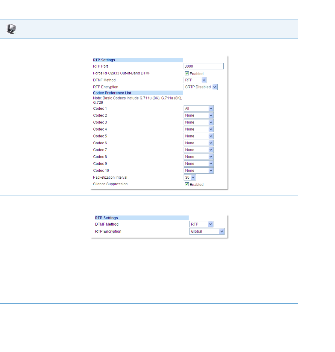
Global SIP Settings
4-82 41-001343-02 REV04 – 05.2014
Aastra Web UI
1. Click on Advanced Settings->Global SIP->RTP Settings.
Global Settings.
Click on Advanced Settings->Line <N>->RTP Settings.
Per-Line Settings.
2. Enter an RTP Port Base in the RTP Port field. Default is 3000.
The RTP Port indicates the port through which the RTP packets are sent. This value must specify the beginning of the RTP port range on the
gateway or router. The RTP port is used for sending DTMF tones and for the audio stream. Your network administrator may close some ports
for security reasons. You may want to use this parameter to send RTP data using a different port.
Note:
The phones support decoding and playing out DTMF tones sent in SIP INFO requests. The following DTMF tones are supported:
•Support signals 0-9, #, *
•Support durations up to 5 seconds
3. The "Force RFC2833 Out-of-Band DTMF" field is enabled by default. Disable this field by unchecking the box.
Enabling this parameter forces the IP phone to use out-of-band DTMF according to RFC2833.
4. Select a method to use from the “DTMF Method” list box. Valid values are RTP, SIP Info, Both. Default is RTP.
Note:
You can configure the DTMF Method on a global or per-line basis.
5. Select the type of RTP encryption to use from the “RTP Encryption” list box. Valid values are SRTP
Disabled, SRTP Preferred, or SRTP Only. Default is SRTP Disabled.
Note:
You can configure RTP Encryption on a global or per-line basis.

Global SIP Settings
41-001343-02 REV04 – 05.2014 4-83
6. In the Codec Preference List, select a codec (with its payload type) you want the phones to use. Valid values are:
•All
•Basic (G.711 u-law, G.711 a-law, G.729)
•G722
•G711u/8K
•G711u/16K
•G711a/8K
•G711a/16K
•G729
•G726-16
•G726-24
•G726-32
•G726-40
•BV16 (8K)
•BV32 (16K)
•L16 (8K)
•L16 (16K)
•AMR (Licensed feature for 6735i, 6737i, 6863i, 6865i, and 6867i only)
•AMR-WB (G.722.2) (Licensed feature for 6735i, 6737i, 6863i, 6865i, and 6867i only)
Notes:
•Setting Codec 1 to “All” ignores the packetization interval (ptime). The packetization interval setting defaults to 30, which is the default for
all codecs.
•Setting Codec 1 to “All” automatically sets all other codec preference fields 2 through 10 to “None”.
•Setting Codec 1 to “Basic” and all other codec preferences in 2 through 10 to “None”, forces the phone to use only the basic codecs as in
previous releases (G.711 u-law, G.711 a-law, and G.729). If you select an additional codec to use in the codec preferences 2 through 10
fields, those codecs are added to the list of Basic codecs for the phone to use.
7. (Optional) In Codec 2 through Codec 10, select a preference of codecs (with its payload type) to use on the phone. Valid values are:
•None
•G722
•G711u/8K
•G711u/16K
•G711a/8K
•G711a/16K
•G729
•G726-16
•G726-24
•G726-32
•G726-40
•BV16 (8K)
•BV32 (16K)
•L16 (8K)
•L16 (16K)
•AMR (Licensed feature for 6735i, 6737i, 6863i, 6865i, and 6867i only)
•AMR-WB (G.722.2) (Licensed feature for 6735i, 6737i, 6863i, 6865i, and 6867i only)
Note:
You can select up to 9 codecs in addition to the codec you selected in step 6.
8. In the “Packetization Interval” field, select the time, in milliseconds. Valid values are 5 to 90, in increments of 5 milliseconds.
9. The “Silence Suppression” field is enabled by default. Disable this field by unchecking the check box.
When enabled, the phone negotiates whether or not to use silence suppression. Disabling this feature forces the phone to ignore any nego-
tiated value.
10. Click Save Settings to save your changes.
Aastra Web UI

Global SIP Settings
4-84 41-001343-02 REV04 – 05.2014
RTCP Summary Reports
The IP phones include the capability of enabling/disabling the generation of RTCP summary reports using the SIP vq-
rtcpxr event package. These RTCP summary reports include voice quality statistics according to draft-ietf-sipping-rtcp-
summary-05 specifications including packet loss, jitter, and delay statistics, as well as call quality scores. When this fea-
ture is enabled, an RTCP summary report is sent at the end of each call via a PUBLISH message to the configuration
server.
In addition to enabling/disabling the generation of these reports, you must specify the hostname and port of the entity,
known as the collector, receiving the reports. Similar to the other IP Phone SIP account parameters, the RTCP summary
report parameters can be set on a global or a per-line basis using the configuration files only.
The RTCP summary report parameters are:
•sip rtcp summary reports
•sip LineN rtcp summary reports
•sip rtcp summary report collector
•sip LineN rtcp summary report collector
•sip rtcp summary report collector port
•sip LineN rtcp summary report collector port
Limitations
The following is a limitation when enabling RTCP summary reports on the phone:
•The call must be at least 5 seconds long in order to generate the RTCP extended reports.
Configuring RTCP Summary Reports
Use the following procedure to configure RTCP summary reports.
Autodial Settings
The IP phones include a feature called “Autodial”. When you configure Autodial on an IP phone, the phone automatically
dials a pre-configured number whenever it is off-hook. Depending on the configuration you specify, the Autodial func-
tions as either a “hotline”, o r a s a “ warmline,” as follows:
•Hotline (default): The IP phone immediately dials a preconfigured number when you lift the handset.
•Warmline: The IP phone waits for a specified amount of time after you lift the handset before dialing a pre-configured
number. If you do not dial a number within the time allotted, then the IP phone begins to dial the number.
By default, the Autodial feature functions as a hotline. If you want Autodial to function as a warmline, you can use the
Autodial “time-out” parameter to specify the length of time (in seconds) the IP phone waits before dialing a pre-config-
ured number.
Note:
The transport protocol used for RTCP summary reports is also configurable. Refer to Configurable Transport Protocol
for SIP Services and RTCP Summary Reports on page 6-40 for more information.
Configuration Files
For specific parameters you can set in the configuration files, see Appendix A, the section, “RTCP Summary Reports” on pageA-37.
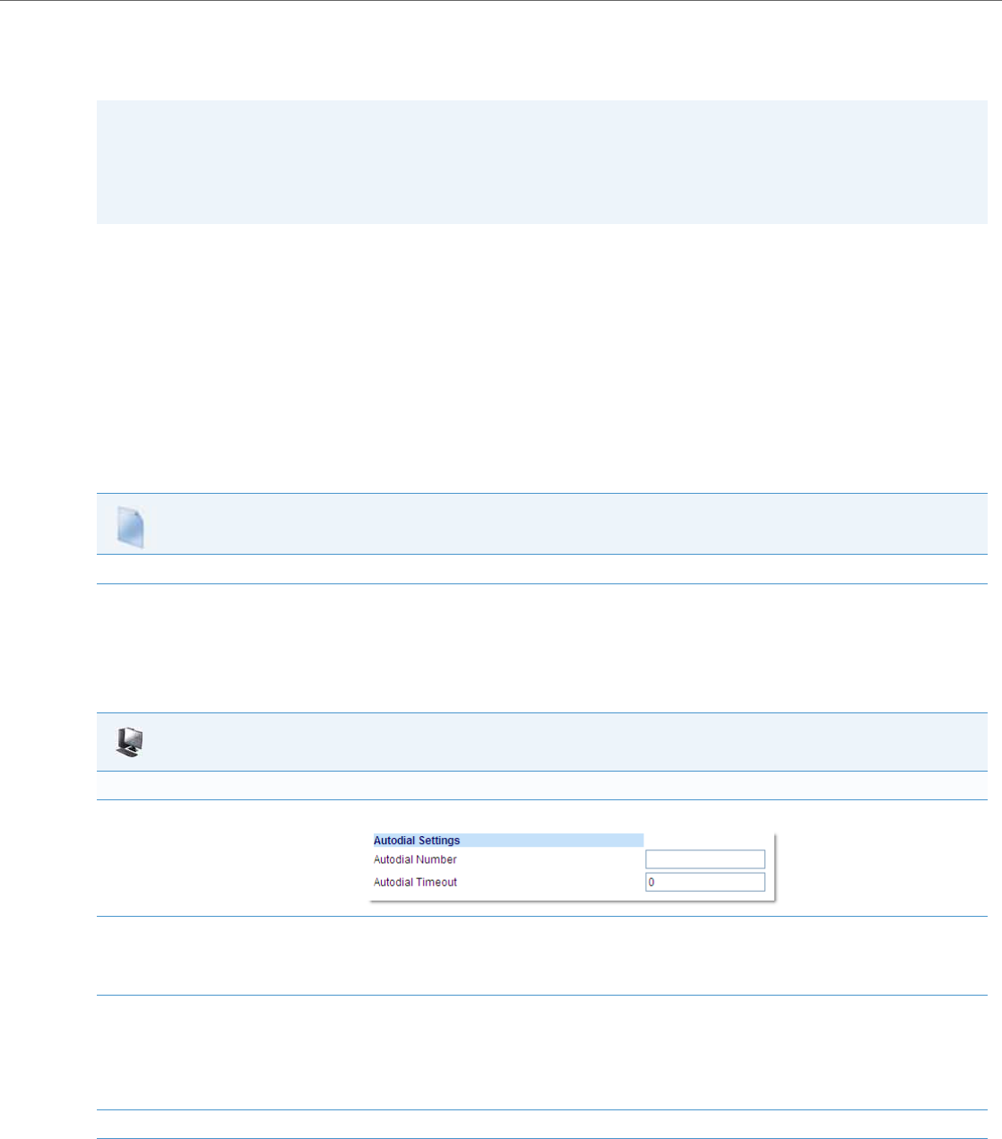
Global SIP Settings
41-001343-02 REV04 – 05.2014 4-85
As administrator, you configure Autodial globally, or on a per-line basis, for an IP phone. The line setting overrides the glo-
bal setting. For example, you can disable Autodial on a specific line simply by setting the line’s autodial number parameter
to empty (blank).
Configuring Autodial Using the Configuration Files
You use the following parameters to configure Autodial using the configuration files:
Global Configuration:
•sip autodial number
•sip autodial timeout
Per-Line Configuration:
•sip lineN autodial number
•sip lineN autodial timeout
Configuring Autodial Using the Aastra Web UI
Use the following procedure to configure Autodial using the Aastra Web UI.
By default, your IP phone uses the global settings you specify for Autodial for all lines on your IP phone. However, you can
also configure Autodial on a per-line basis.
Warning!
Before configuring Autodial on your IP phone:
•Any speeddial numbers that you configure on an IP phone are not affected by autodial settings.
•If you configure autodial on your IP phone, any lines that function as hotlines do not accept conference calls, trans-
ferred calls, and/or intercom calls.
Configuration Files
For specific parameters you can set in the configuration files, see Appendix A, the section, “Autodial Settings” on pageA-104.
Aastra Web UI
Global Configuration
1. Click on Advanced Settings->Global SIP->Autodial Settings.
2. In the “Autodial Number” field, specify the SIP number that the IP phone dials whenever the IP phone is off-hook. An empty (blank) value
disables autodial on the phone.
For example: 8500
3. In the “Autodial Timeout” field, specify a value, in seconds, for the timer as follows:
•If you want the IP phone to autodial the number immediately (hotline) whenever the IP phone is off-hook, accept the default value of 0.
•If you want to specify a length of time for the IP phone to wait before dialing the number, enter the length of time (in seconds). For exam-
ple: 30
Valid values are 0 to 120.
4. Click Save Settings to save your changes.
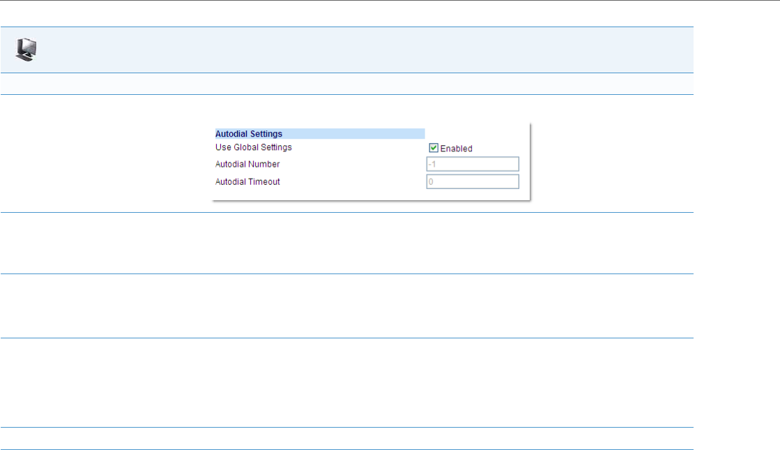
Global SIP Settings
4-86 41-001343-02 REV04 – 05.2014
Per-Line Configuration
1. Click on Advanced Settings->Line <1 - 9>->Autodial Settings.
2. Perform one of the following actions:
•To allow this line to use the global autodial settings, click on the Use Global Settings parameter to enable it, then click Save Settings to
save your changes.
•To specify a different autodial configuration for this specific line, disable the Use Global Settings parameter. Then proceed to step 3.
3. In the “Autodial Number” field, specify the SIP number for this line that the IP phone dials whenever the IP phone is off-hook as follows:
•If set to -1, then the global autodial settings for this IP phone to this line.
•If set to empty (blank), then disable Autodial on this line.
•If set to a valid SIP number, dial the SIP number specified for this line. For example: 8500
4. In the “Autodial Timeout” field, specify a value, in seconds, for the timer for this line as follows:
•If you want the IP phone to autodial the number immediately (hotline) whenever the IP phone is off-hook, accept the default value of 0.
•If you want to specify a length of time for the IP phone to wait before dialing the number, enter the length of time (in seconds). For exam-
ple: 30
Valid values are 0 to 120.
5. Click Save Settings to save your changes.
Aastra Web UI
Configuration Server Protocol
41-001343-02 REV04 – 05.2014 4-87
Configuration Server Protocol
You can download new versions of firmware and configuration files from the configuration server to the IP phone using
any of the following types of protocols: TFTP, FTP, HTTP, and HTTPS. For each Protocol, you can specify the path for which
the configuration files are located on the server. For HTTP and HTTPS, you can also specify the port number to use for
downloading the phone configuration. For FTP, you can configure a Username and Password that are authenticated by the
FTP server.
The TFTP setting is the default download protocol. You can configure the type of protocol that the IP phones use by set-
ting it in the configuration files, the IP phone UI, or the Aastra Web UI.
Configuring the Configuration Server Protocol
Use the following procedure to configure the configuration server protocol.
Note:
For DHCP to automatically populate the IP address or domain name for the TFTP, FTP, HTTP, or HTTPS server, your DHCP
server must support download protocol as referenced in RFC2131 and RFC1541 for Option 66. For more information,
see this chapter, the section, “DHCP” on page4-3.
Configuration Files
For specific parameters you can set in the configuration files, see Appendix A, the section, “Configuration Server Settings” on pageA-16.
IP Phone UI
1. Press on the phone to enter the Options List.
2. Select Administrator Menu.
3. Enter your Administrator password.
Note:
The IP Phones accept numeric passwords only.
4. Select Configuration Server.
5. Select Download Protocol.
6. Select from the following:
•Use TFTP
•Use FTP
•Use HTTP
•Use HTTPS
Default is “Use TFTP”.
The IP phone uses the protocol you select to download new firmware and configuration files from the configuration server.
7. Press Done (8 and 11-Line LCD phones) or Set (3-Line LCD phones) to save the changes.
8. From the Configuration Server menu, select from the following. This selection is dependent on the Download Protocol you selected in
step 6.
TFTP Settings
FTP Settings
HTTP Settings
HTTPS Settings

Configuration Server Protocol
4-88 41-001343-02 REV04 – 05.2014
9. Enter the IP address of the protocol server (in dotted decimal format).
Use the following table to configure the applicable server.
IP Phone UI
TFTP Settings
•Select Primary TFTP
•Enter the IP address or fully qualified domain name of the primary TFTP server.
•Press Done or Set to save the change.
•Select Pri TFTP Path.
•Enter the path name for which the configuration files reside on the TFTP server for downloading to the IP
Phone. If the IP phone’s files are located in a sub-directory beneath the server’s root directory, the relative path
to that sub-directory should be entered in this field. Enter the path name in the form folderX\folderX\folderX. For
example, ipphone\6757i\configfiles.
•Optional: You can also configure an Alternate TFTP server and Alternate TFTP Path if required by selecting the
“Alternate TFTP” and the “Alt TFTP Path” parameters.
•From the TFTP Settings menu, select Alternate TFTP and press Enter.
•Enter the IP address or fully qualified domain name of the alternate TFTP server.
•Press Done or Set to save the change.
•Select Alt TFTP Path.
•Enter the path name for which the configuration files reside on the Alternate TFTP server for downloading to
the IP Phone. If the IP phone’s files are located in a sub-directory beneath the server’s root directory, the relative
path to that sub-directory should be entered in this field. Enter the path name in the form
folderX\folderX\folderX. For example, ipphone\6757i\configfiles.
FTP Settings
•Select FTP Server.
•Enter the IP address or fully qualified domain name of the FTP server.
•Press Done or Set to save the change.
•Select FTP Path.
•Enter the path name for which the configuration files reside on the FTP server for downloading to the IP Phone.
If the IP phone’s files are located in a sub-directory beneath the server’s root directory, the relative path to that
sub-directory should be entered in this field. Enter the path name in the form folderX\folderX\folderX. For exam-
ple, ipphone\6757i\configfiles.
•Optional: You can enter a username and password for accessing the FTP server if required:
•Select FTP Username.
•Enter a username for accessing the FTP server.
•Press Done.
•Select FTP Password.
•Enter a password for accessing the FTP server.
•Press Done or Set.

Configuration Server Protocol
41-001343-02 REV04 – 05.2014 4-89
Note:
For more information on configuring the HTTPS security method, HTTP to HTTPS redirect, and HTTPS server blocking for HTTP XML
POSTs, see the section, “HTTPS Client/Server Configuration” on page4-33.
10. Press Done or Set repeatedly until the session prompts you to restart the IP phone to apply the configuration settings.
11. Select Restart.
IP Phone UI
HTTP Settings
•Select HTTP Server
•Enter the IP address of the HTTP server.
•Press Done or Set.
•Select HTTP Path.
•Enter the path name for which the configuration files reside on the HTTP server for downloading to the IP
Phone. If the IP phone’s files are located in a sub-directory beneath the server’s root directory, the relative path
to that sub-directory should be entered in this field. Enter the path name in the form folderX\folderX\folderX. For
example, ipphone\6757i\configfiles.
•Select HTTP Port.
•Enter the HTTP port that the server uses to load the configuration to the phone over HTTP. Default is 80.
•Press Done or Set.
HTTPS Settings
•Select HTTP Client.
•Select Download Server.
•Enter the IP address of the HTTPS server.
•Press Done or Set.
•Select Download Path.
•Enter the path name for which the configuration files reside on the HTTPS server for downloading to the IP
Phone. If the IP phone’s files are located in a sub-directory beneath the server’s root directory, the relative path
to that sub-directory should be entered in this field. Enter the path name in the form folderX\folderX\folderX. For
example, ipphone\6757i\configfiles.
•Press Done or Set.
•Select Client Method.
•Select the client method to use for downloading the configuration files (SSl 3.0 or TLS 1.0). For more informa-
tion about which client method to use, see the section, “HTTPS Client/Server Configuration” on page4-33.
•Select Download Port.
•Enter the HTTPS port that the server uses to load the configuration to the phone over HTTPS. Default is 443.
•Select HTTPS Server.
•Select HTTP->HTTPS.
•For 3-Line LCD Displays:
–Press Change to select “Do not redirect” or “Redirect”. D ef au l t is “Do not redirect”. Enabling this feature
redirects the HTTP protocol to HTTPS.
–Press Set.
•For 8 and 11-Line LCD Displays:
–Press Change to select “Yes” and redirect HTTP to HTTPS. Select “No” to not direct HTTPS to HTTPS, Default
is “No”. Enabling this feature redirects the HTTP protocol to HTTPS.
–Press Done.
•Select XML HTTP POSTs.
•For 3-Line LCD Displays:
–Press Change to select “Do not block” or “Block”. Enabling this feature blocks XML HTTP POSTs from the IP
Phone.
•For 8 and 11-Line LCD Displays:
–Press Change to select “Yes” and block XML HTTP Posts. Select “No” to unblock XML HTTP Posts. Default is
“No”. E n a bl i n g t hi s f e at ur e bl oc ks XML HTTP POSTs from the IP Phone.

Configuration Server Protocol
4-90 41-001343-02 REV04 – 05.2014
For the 6739i:
IP Phone UI
1. Press the Options key on the phone to enter the Options List.
2. Press the Advanced button. A keyboard displays.
3. Enter the Administrator password using the keyboard. Default is “22222”.
4. Press Cfg. Svr.
5. Press the Download Protocol field, and press the value you want the phone to use for downloading from the configuration server. Valid val-
ues are:
•TFTP (Default)
•FTP
•HTTP
•HTTPS
The IP phone uses the protocol you select to download new firmware and configuration files from the configuration server.
6. After selecting the download protocol, you must identify specific parameters for that protocol. On the Cfg. Svr screen, press the button asso-
ciated with the download protocol you selected in step 6.
7. Use the following table to configure the applicable server.
TFTP Settings
•Press TFTP Server.
•Enter the IP address or fully qualified domain name of the primary TFTP server.
•Press TFTP Path.
•Enter the path name for which the configuration files reside on the TFTP server for downloading to the IP
Phone. If the IP phone’s files are located in a sub-directory beneath the server’s root directory, the relative path
to that sub-directory should be entered in this field. Enter the path name in the form folderX\folderX\folderX. For
example, ipphone\6757i\configfiles.
•Optional: You can also configure an Alternate TFTP server and Alternate TFTP Path if required by selecting the
“Alternate TFTP” and the “Alt TFTP Path” parameters.
•Press Use Alternate TFTP, and press “Yes” to use an alternate TFTP server.
Default is “No”.
•Press Alternate TFTP Server.
•Enter the IP address or fully qualified domain name of the alternate TFTP server.
•Press Alt. TFTP Path.
•Enter the path name for which the configuration files reside on the Alternate TFTP server for downloading to
the IP Phone. If the IP phone’s files are located in a sub-directory beneath the server’s root directory, the relative
path to that sub-directory should be entered in this field. Enter the path name in the form
folderX\folderX\folderX. For example, ipphone\6757i\configfiles.
FTP Settings
•Press FTP Server.
•Enter the IP address or fully qualified domain name of the FTP server.
•Press FTP Path.
•Enter the path name for which the configuration files reside on the FTP server for downloading to the IP Phone.
If the IP phone’s files are located in a sub-directory beneath the server’s root directory, the relative path to that
sub-directory should be entered in this field. Enter the path name in the form folderX\folderX\folderX. For exam-
ple, ipphone\6757i\configfiles.
•Optional: You can enter a username and password for accessing the FTP server if required:
•Press FTP Username.
•Enter a username for accessing the FTP server.
•Press FTP Password.
•Enter a password for accessing the FTP server.

Configuration Server Protocol
41-001343-02 REV04 – 05.2014 4-91
For the 6867i:
8. Press until the Options List screen displays.
9. Press Restart to restart the phone for the change to take affect.
IP Phone UI
1. Press on the phone to enter the Options List.
2. Press the Advanced softkey.
3. Enter the Administrator password using the keypad. Default is “22222”.
4. Select Configuration Server.
5. In the Download Protocol field,select the protocol you want the phone to use for downloading from the configuration server. Valid values
are:
•TFTP (Default)
•FTP
•HTTP
•HTTPS
The IP phone uses the protocol you select to download new firmware and configuration files from the configuration server.
6. After selecting the download protocol, you must identify specific parameters for that specific protocol.
IP Phone UI
HTTP Settings
•Press HTTP Server.
•Enter the IP address of the HTTP server.
•Press HTTP Port.
•Enter the HTTP port that the server uses to load the configuration to the phone over HTTP. Default is 80.
•Press HTTP Path.
•Enter the path name for which the configuration files reside on the HTTP server for downloading to the IP
Phone. If the IP phone’s files are located in a sub-directory beneath the server’s root directory, the relative path
to that sub-directory should be entered in this field. Enter the path name in the form folderX\folderX\folderX. For
example, ipphone\6757i\configfiles.
HTTPS Settings
•Press HTTPS Server.
•Enter the IP address of the HTTPS server.
•Press HTTPS Port.
•Enter the HTTPS port that the server uses to load the configuration to the phone over HTTPS. Default is 443.
•Press HTTPS Path.
•Enter the path name for which the configuration files reside on the HTTPS server for downloading to the IP
Phone. If the IP phone’s files are located in a sub-directory beneath the server’s root directory, the relative path
to that sub-directory should be entered in this field. Enter the path name in the form folderX\folderX\folderX. For
example, ipphone\6757i\configfiles.
•Press HTTPS Client Method.
•Select the client method to use for downloading the configuration files (SSl 3.0 or TLS 1.0). For more informa-
tion about which client method to use, see the section, “HTTPS Client/Server Configuration” on page4-33.

Configuration Server Protocol
4-92 41-001343-02 REV04 – 05.2014
7. Use the following table to configure the applicable server.
8. Press the Save softkey.
9. Restart the phone for the change to take affect.
IP Phone UI
TFTP Settings
•In the Primary Server field, enter the IP address or fully qualified domain name of the primary TFTP server.
•In the Pri TFTP Path field, enter the path name for which the configuration files reside on the TFTP server for
downloading to the IP Phone. If the IP phone’s files are located in a sub-directory beneath the server’s root
directory, the relative path to that sub-directory should be entered in this field. Enter the path name in the form
folderX\folderX\folderX. For example, ipphone\6867i\configfiles.
•Optional: You can also configure an Alternate TFTP server and Alternate TFTP Path if required by selecting the
Use Alt TFTP checkbox and entering the alternate path in the Alt TFTP Path field.
FTP Settings
•In the FTP Server field, enter the IP address or fully qualified domain name of the FTP server.
•In the FTP Path field, enter the path name for which the configuration files reside on the FTP server for down-
loading to the IP Phone. If the IP phone’s files are located in a sub-directory beneath the server’s root directory,
the relative path to that sub-directory should be entered in this field. Enter the path name in the form
folderX\folderX\folderX. For example, ipphone\6867i\configfiles.
•Optional: You can enter a username and password for accessing the FTP server if required by entering them in
the FTP Username and FTP Password fields.
HTTP Settings
•In the HTTP Server field, enter the IP address of the HTTP server.
•In the HTTP Port field, enter the HTTP port that the server uses to load the configuration to the phone over
HTTP. Default is 80.
•In the HTTP Path field, enter the path name for which the configuration files reside on the HTTP server for
downloading to the IP Phone. If the IP phone’s files are located in a sub-directory beneath the server’s root
directory, the relative path to that sub-directory should be entered in this field. Enter the path name in the form
folderX\folderX\folderX. For example, ipphone\6867i\configfiles.
HTTPS Settings
•In the HTTPS Server field, enter the IP address of the HTTPS server.
•In the HTTPS Port field, enter the HTTPS port that the server uses to load the configuration to the phone over
HTTPS. Default is 443.
•In the HTTPS Path field, enter the path name for which the configuration files reside on the HTTPS server for
downloading to the IP Phone. If the IP phone’s files are located in a sub-directory beneath the server’s root
directory, the relative path to that sub-directory should be entered in this field. Enter the path name in the form
folderX\folderX\folderX. For example, ipphone\6867i\configfiles.
•In the HTTPS Client Method field, select the client method to use for downloading the configuration files (SSl
3.0 or TLS 1.0). For more information about which client method to use, see the section, “HTTPS Client/Server
Configuration” on page4-33.
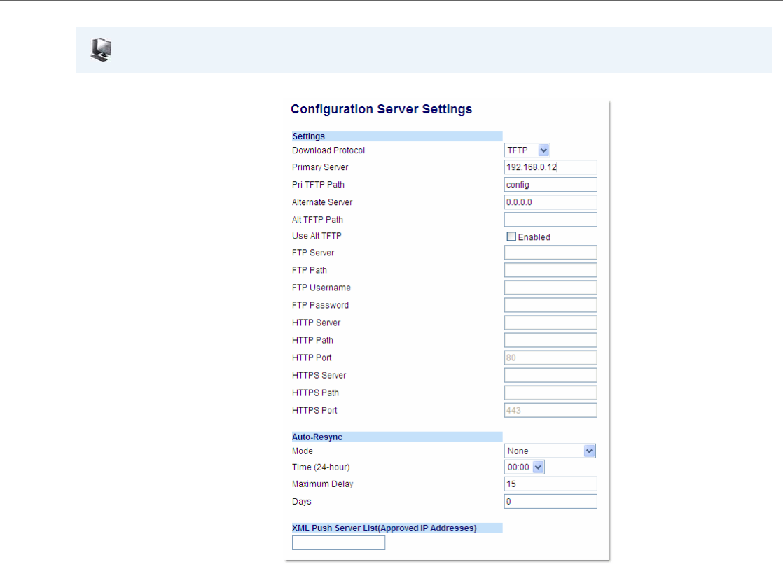
Configuration Server Protocol
41-001343-02 REV04 – 05.2014 4-93
Aastra Web UI
1. Click on Advanced Settings->Configuration Server.

Configuration Server Protocol
4-94 41-001343-02 REV04 – 05.2014
2. Select the protocol from the "Download Protocol" list box. Valid values are TFTP, FTP, HTTP, and HTTPS. Default is TFTP.
The IP phone uses the protocol you select to download new firmware and configuration files from the configuration server. Use the following
table to configure the applicable server.
Note:
For more information on configuring the HTTPS security method, HTTP to HTTPS redirect, and HTTPS server blocking for HTTP XML POSTs,
see the section, “HTTPS Client/Server Configuration” on page4-33.
3. Click Save Settings to save your settings.
Note:
The session prompts you to restart the IP phone to apply the configuration settings.
4. Select Operation->Reset and click Restart.
Aastra Web UI
TFTP
•Enter an IP address or fully qualified domain name in the "TFTP Server" field.
•Enter the path name in the “TFTP Path” field for which the configuration files reside on the TFTP server for
downloading to the IP Phone. If the IP phone’s files are located in a sub-directory beneath the server’s root
directory, the relative path to that sub-directory should be entered in this field. Enter the path name in the
form folderX\folderX\folderX. For example, ipphone\6757i\configfiles.
•Optional: You can also configure an alternate TFTP server if required. If "Use Alternate TFTP" is enabled, you
must also enter an IP address or qualified domain name for the alternate server in the "Alternate TFTP" field.
You can also enter a path name for the alternate TFTP server in the “Alternate TFTP Path” field.
FTP
•Enter an IP address or fully qualified domain name in the "FTP Server" field.
•Enter the path name in the “FTP Path” field for which the configuration files reside on the FTP server for down-
loading to the IP Phone. If the IP phone’s files are located in a sub-directory beneath the server’s root directory,
the relative path to that sub-directory should be entered in this field. Enter the path name in the form
folderX\folderX\folderX. For example, ipphone\6757i\configfiles.
•Optional: You can enter a username and password for accessing the FTP server if required.
•Enter a username for a user that will access the FTP server in the "FTP User Name" field.
•Enter a password for a user that allows access to the FTP server in the "FTP Password" field.
HTTP
•Enter an IP address or fully qualified domain name in the "HTTP Server" field.
•Enter the path name in the “HTTP Path” field for which the configuration files reside on the HTTP server for
downloading to the IP Phone. If the IP phone’s files are located in a sub-directory beneath the server’s root
directory, the relative path to that sub-directory should be entered in this field. Enter the path name in the
form folderX\folderX\folderX. For example, ipphone\6757i\configfiles.
•Enter the HTTP port number in the “HTTP Port” field that the server uses to load the configuration to the
phone over HTTP.
•Optional: You can enter a list of users to be authenticated when they access the HTTP server in the "XML Push
Server List (Approved IP Addresses)" field.
HTTPS
•Enter an IP address or fully qualified domain name in the "HTTPS Server" field.
•Enter the path name in the “HTTPS Path” field for which the configuration files reside on the HTTP server for
downloading to the IP Phone. If the IP phone’s files are located in a sub-directory beneath the server’s root
directory, the relative path to that sub-directory should be entered in this field. Enter the path name in the
form folderX\folderX\folderX. For example, ipphone\6757i\configfiles.
•Enter the HTTPS port number in the “HTTPS Port” field that the server uses to load the configuration to the
phone over HTTPS.
•Optional: You can enter a list of users to be authenticated when they access the HTTP server in the "XML Push
Server List (Approved IP Addresses)" field.

41-001343-02 REV04 – 05.2014 5-1
Chapter 5
Configuring Operational Features
About this Chapter
The IP phones have specific operational features you can configure to customize your IP phone. This chapter describes
each feature and provides procedures for configuring your phone to use these features.
Topics
This chapter covers the following topics:
Topic Page
Operational Features page5-4
User Passwords page5-4
Administrator Passwords page5-7
Locking/Unlocking the Phone page5-7
Defining an Emergency Dial Plan page5-12
Configurable Emergency Call Behavior page5-14
User Dial Plan Setting page5-14
Time and Date page5-15
Backlight Mode page5-27
Display page5-28
Background Image on Idle Screen page5-30
Configurable Home/Idle Screen Modes page5-31
Picture ID Feature page5-32
Audio DHSG Headset page5-33
Configurable Bluetooth Support page5-34
Audio Hi-Q on G.722 Calls page5-35
Wideband Audio Equalizer page5-35
Audio Transmit and Receive Gain Adjustments page5-36
Live Dialpad page5-37
Language page5-38
Minimum Ringer Volume page5-49
Locking IP Phone Keys page5-49
Locking/Unlocking the SAVE and DELETE keys page5-51
Local Dial Plan page5-52
Suppressing DTMF Playback page5-55
Display DTMF Digits page5-55
Filter Out Incoming DTMF Events page5-56

About this Chapter
5-2 41-001343-02 REV04 – 05.2014
Call Waiting page5-57
Stuttered Dial Tone page5-61
XML Beep Support page5-62
Status Scroll Delay page5-63
Switch Focus to Ringing Line page5-64
Call Hold Reminder During Active Calls page5-65
Call Hold Reminder (on Single Hold) page5-66
Call Hold Reminder Timer & Frequency page5-67
Preferred Line and Preferred Line Timeout page5-68
Goodbye Key Cancels Incoming Call page5-69
Message Waiting Indicator Line page5-71
Customizable Message Waiting Indicator (MWI) Request URI page5-72
DND Key Mode page5-73
Call Forward Mode page5-75
Link Layer Discovery Protocol for Media Endpoint Devices (LLDP-MED) and Emergency Location Identification Number (ELIN) page5-77
Incoming/Outgoing Intercom with Auto-Answer and Barge In page5-79
Group Paging RTP Settings page5-82
Speeddial Key Mapping page5-84
Send DTMF for Remapping Conference or Redial Key page5-86
Ring Tones and Tone Sets page5-87
Ring Tone via Speaker During Active Calls page5-90
No Service Congestion Tone page5-91
Priority Alerting page5-92
Directed Call Pickup (BLF or XML Call Interception) page5-98
Softkeys/Programmable Keys/Feature Keys/Expansion Module Keys page5-104
Shifting of Softkey Positions for Busy States page5-113
Option to Remove the “More” Softkey when Not Required page5-113
Increased Number of Displayed Characters for Softkey Line Labels page5-117
6757i Cordless (CT) Feature Keys page5-118
Press-and-Hold Speeddial Keypad Keys page5-123
6867i Hard Key Reprogramming page5-124
Customizing the Key Type List in the Aastra Web UI page5-127
Speeddial Prefixes page5-128
Enabling/Disabling Ability to Add or Edit a Speeddial Key page5-128
Busy Lamp Field (BLF) page5-128
BLF Page Switch Feature page5-132
Configurable Display for Blank BLF/List Softkeys page5-133
Ring Signal Type for BLF page5-133
BLF Subscription Period page5-137
Topic Page

About this Chapter
41-001343-02 REV04 – 05.2014 5-3
BLF/Xfer and Speeddial/Xfer Keys page5-138
Speeddial/Conference Key page5-141
Speeddial/MWI Key page5-143
Automatic Call Distribution (ACD) (for Sylantro Servers) page5-147
Directed Call Pickup/Group Call Pickup page5-151
Do Not Disturb (DND) page5-154
Bridged Line Appearance (BLA) page5-166
BLA Support for Third-Party Registration page5-171
P-Preferred Identity Header for BLA Accounts page5-172
BLA Support for Message Waiting Indicator (MWI) page5-172
Shared Call Appearance (SCA) Call Bridging page5-174
Park/Pick Up Static and Programmable Configuration page5-177
Enhanced Park/Pickup Configuration Method (BroadSoft BroadWorks) page5-185
Last Call Return (lcr) (Sylantro Servers) page5-188
Call Forwarding page5-190
Configuring Call Forward via the IP Phone UI (6867i) page5-216
Display Name Customization page5-219
Displaying Call Destination for Incoming Calls page5-221
Callers List page5-221
Customizable Callers List and Services Keys page5-224
Missed Calls Indicator page5-225
Directory List page5-226
Customizable Directory List Key page5-235
Voicemail page5-235
Visual Indicators for Voicemail on SCA-Configured Lines page5-237
PIN and Authorization Code Suppression page5-238
XML Customized Services page5-239
XML Override for a Locked Phone page5-264
Configurable Indication of Terminated Calls page5-265
Centralized Conferencing (for Sylantro and Broadsoft Servers) page5-265
Custom Ad-Hoc Conference page5-269
“SIP Join” Feature for 3-Way Conference page5-269
Conference/Transfer Support for Live Dial Mode page5-270
Authentication Support for HTTP/HTTPS Download Methods, used with Broadsoft Client Management System (CMS) page5-270
Customizing the Display Columns on the M675i Expansion Module page5-272
Topic Page
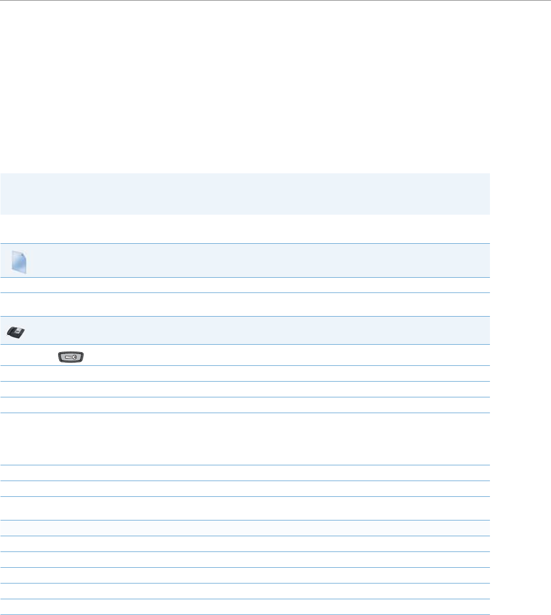
Operational Features
5-4 41-001343-02 REV04 – 05.2014
Operational Features
Description
This section describes the operational features managed and configured by a System Administrator.
User Passwords
A user or an administrator can change the user passwords on the phone using the configuration files, the IP phone UI, or
the Aastra Web UI.
Use the following procedures to change the user password.
Configuring a User Password
Note:
The IP phones support numeric characters only in passwords. If you enter a password with alpha characters, the phone
uses the default password instead.
Configuration Files
For specific parameters you can set in the configuration files, see Appendix A, the section, “Password Settings” on pageA-14.
IP Phone UI
1. Press on the phone to enter the Options List.
2. Select User Password.
3. Enter the current user password.
4. Press Enter.
5. Enter the new user password.
Note:
The IP phones support numeric characters only in passwords. If you enter a password with alpha characters, the phone uses the default pass-
word instead.
6. Press Enter.
7. Re-enter the new user password.
8. Press Enter.
A message, "Password Changed" displays on the screen.
For the 6739i:
1. Press the Options key on the phone to enter the Options List.
2. Press Password. A keyboard displays.
3. Press on the “Current Password” text box, and enter the current user password.
4. Press on the “New Password” text box, and enter the new user password.
5. Press on the “Re-enter Password” text box, and re-enter the user password.
6. Press Save. The Options screen displays indicating your changes were saved.
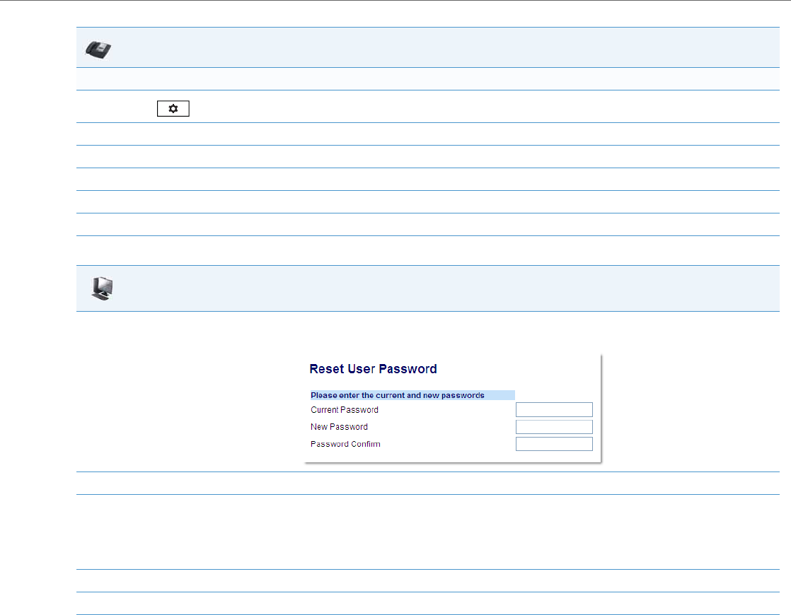
Operational Features
41-001343-02 REV04 – 05.2014 5-5
For the 6867i:
1. Press to enter the Options List.
2. Select Lock > Password.
3. Press on the “Current Password” text box, and enter the current user password.
4. Press on the “New Password” text box, and enter the new user password.
5. Press on the “Re-enter Password” text box, and re-enter the user password.
6. Press Save. The Options screen displays indicating your changes were saved.
Aastra Web UI
1. Click on Operation->User Password.
2. In the "Current Password" field, enter the current user password.
3. In the "New Password" field, enter the new user password.
Note:
The IP phones support numeric characters only in passwords. If you enter a password with alpha characters, the phone uses the default pass-
word instead.
4. In the "Password Confirm" field, enter the new user password again.
5. Click Save Settings to save your changes.
IP Phone UI
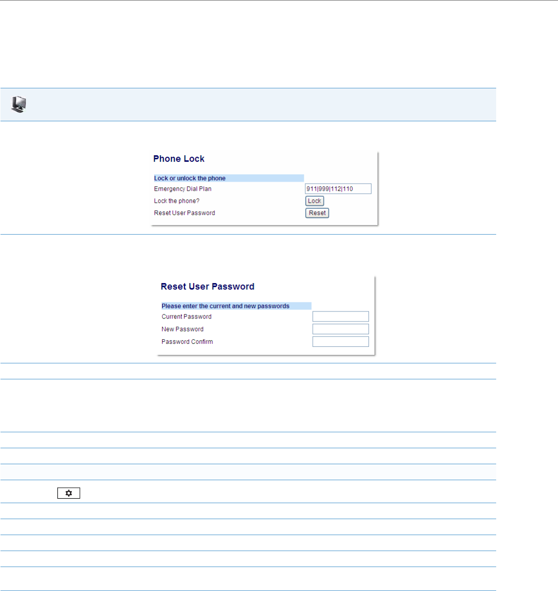
Operational Features
5-6 41-001343-02 REV04 – 05.2014
Resetting a User Password
If a user forgets his password, either the user or an administrator can reset it so a new password can be entered. The reset
user password feature resets the password to the factory default which is blank (no password).
You can reset a user password using the Aastra Web UI only at the path Operation->Phone Lock. Use the following proce-
dure to reset a user password.
Aastra Web UI
1. Click on Operation->Phone Lock.
2. In the “Reset User Password” field, click Reset.
The following screen displays:
3. In the “Current Password” field, leave this blank.
4. In the “New Password” field, enter a new password for the user.
Note:
The IP phones support numeric characters only in passwords. If you enter a password with alpha characters, the phone uses the default pass-
word instead.
5. In the “Password Confirm” field, re-enter the new user password.
6. Click Save Settings to save the new user password and perform the next procedure.
For the 6739i:
1. Press on the phone to enter the Options List.
2. Select Lock > Password.
3. Enter the current password in the <Current Password> field.
4. Press the down navigation key and enter the new password in the <New Password> field.
5. Press the down navigation key and enter the new password again in the <Re-enter Password> field.
6. Press the Save softkey.
A message, "Password Changed" displays on the screen.

Operational Features
41-001343-02 REV04 – 05.2014 5-7
Administrator Passwords
An administrator can change the administrator passwords on the phone using the configuration files only.
An administrator can also assign a password for using the Options key on the IP phone. You turn this feature on and off by
entering the "options password enabled" parameter followed by a valid value in the configuration files. Valid values are 0
(false; Options key not password protected), or 1 (true; Options key password protected). If this parameter is set to 1, a user
has to enter a password at the IP phone UI. If the password is entered correctly, the user is allowed to gain access to the
Options Menu and no more password prompts display for other password protected screens. If the user fails to enter the
correct password in three attempts, access to the Options Menu is denied and the IP phone returns to the idle screen.
Changing the Administrator Password
Use the following procedure to change the administrator password.
Locking/Unlocking the Phone
A user or administrator can lock a phone to prevent it from being used or configured. Once the phone is locked, the user or
administrator can enter their password to unlock the phone.
You can lock/unlock a phone using the configuration files, the IP Phone UI, or the Aastra Web UI.
You can use any of the following methods to lock/unlock a phone:
•Using the IP Phone UI at the path Options->Lock.
•Using the Aastra Web UI via the path Operation->Phone Lock.
•Using the configuration files to configure a softkey as “phonelock”, and then pressing the key to lock/unlock the phone.
•Using the Aastra Web UI to configure a softkey as “Phone Lock”, and then pressing the key to lock/unlock the phone.
Configuration Files
For specific parameters you can set in the configuration files, see Appendix A, the section, “Password Settings” on pageA-14.
Note:
All of the methods above configure locking/unlocking of the phone dynamically. Once configured, the feature takes
affect immediately. To unlock the phone, a user or administrator must enter their password.
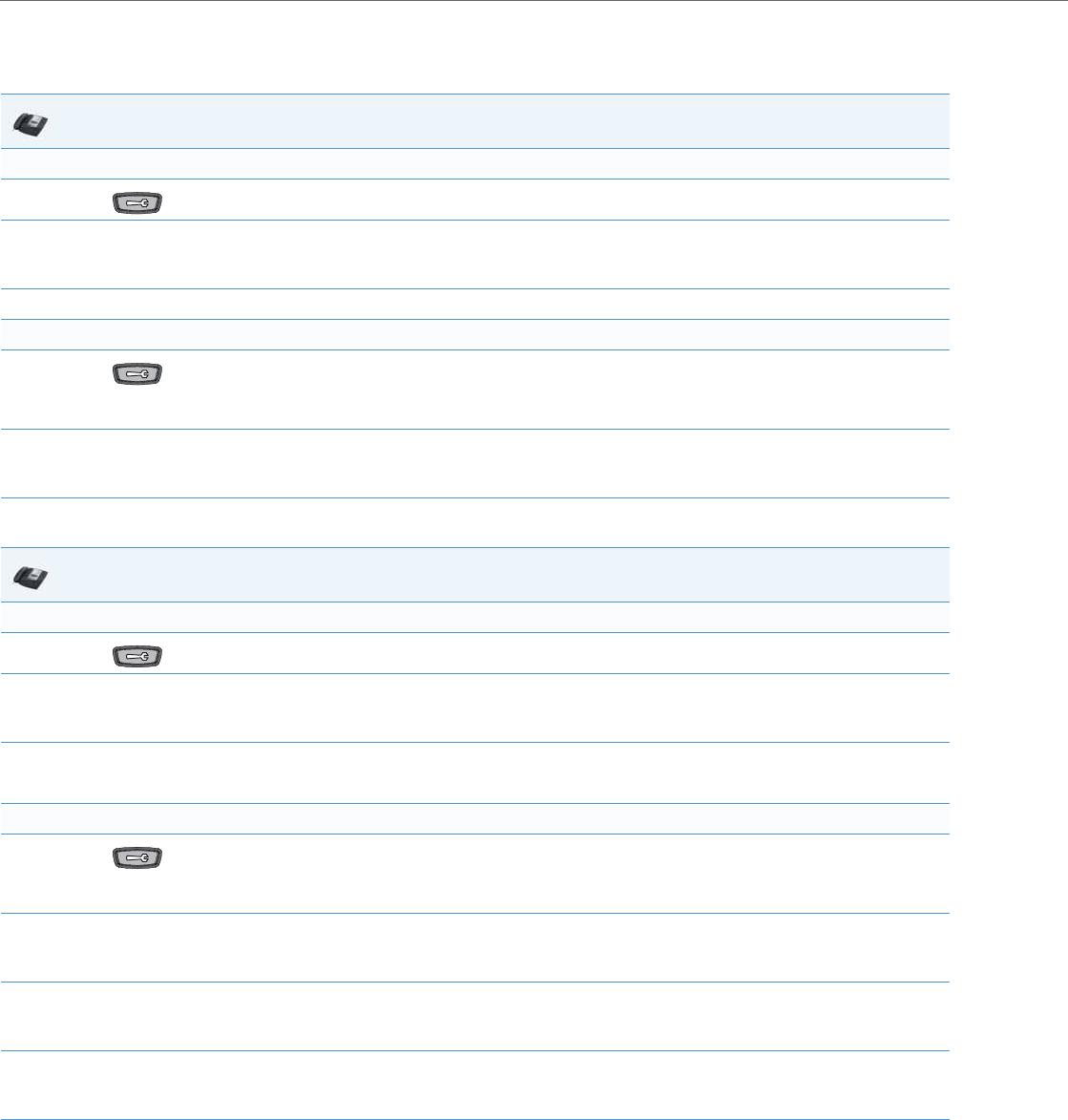
Operational Features
5-8 41-001343-02 REV04 – 05.2014
Locking/Unlocking the Phone Using the IP Phone UI
Use the following IP Phone UI procedure to lock/unlock an IP phone and prevent it from being used or configured.
For the 6739i:
IP Phone UI
Lock the phone:
1. Press on the phone to enter the Options List.
2. Select Phone Lock.
The prompt, “Lock the phone?” displays.
3. Press Lock to lock the phone.
Unlock the phone:
1. Press on the phone to enter the Options List.
The prompt, “To unlock the phone...Password:”
2. Enter the user or administrator password and press Enter. Default is “22222”.
The phone unlocks.
IP Phone UI
Lock the phone:
1. Press on the phone to enter the Options List.
2. Press Lock.
The prompt, “Lock the phone?” displays.
3. Press Ye s to lock the phone
The phone locks.
Unlock the phone:
1. Press on the phone to enter the Options List.
A “Phone is Locked” screen displays allowing you to press an “Unlock the Phone” button.
2. Press Unlock the Phone.
A prompt, “Enter Unlock Password” displays as well as a keyboard.
3. Enter the user or administrator password and press Enter. Default is “22222”.
A prompt “Unlock the Phone?” displays.
4. Press Ye s to unlock the phone.
The phone unlocks.
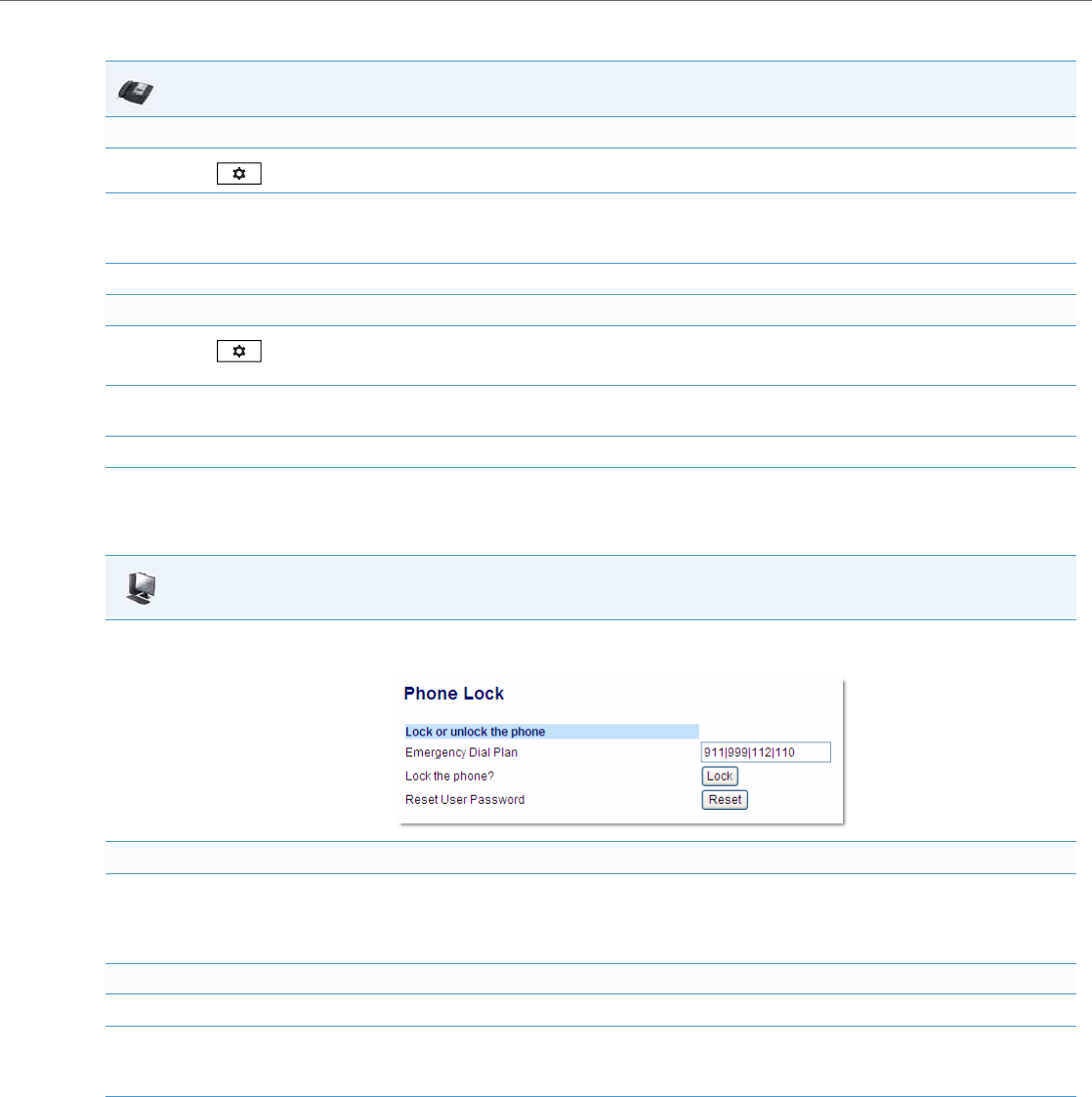
Operational Features
41-001343-02 REV04 – 05.2014 5-9
For the 6867i:
Locking/Unlocking the Phone Using the Aastra Web UI
Use the following Aastra Web UI procedure to lock/unlock an IP phone and prevent it from being used or configured.
Configuring a Lock/Unlock Key Using the Configuration Files
Using the configuration files, you can configure a key on the phone (softkey, programmable key, or expansion module key)
to use as a lock/unlock key. In the configuration files, you assign the function of the key as “phonelock”.
IP Phone UI
Lock the phone:
1. Press on the phone to enter the Options List.
2. Select Lock > Phone Lock.
The prompt, “Lock the phone?” displays.
3. Select Ye s or press the Lock softkey to lock the phone.
Unlock the phone:
1. Press on the phone to enter the Options List.
An “Enter Unlock Password” prompt displays.
2. Enter the user or administrator password and press Enter. Default is “22222”.
A prompt “Unlock the Phone?” displays.
3. Select Ye s or press the Unlock softkey to unlock the phone.
Aastra Web UI
1. Click on Operation->Phone Lock.
Lock the phone:
2. In the “Lock the Phone?” field, click Lock.
The phone locks dynamically and displays the following message:
“Phone is locked”.
Unlock the phone:
3. Click on Operation->Phone Lock.
4. In the “Unlock the Phone?” field, click Unlock.
The phone unlocks dynamically and displays the following message: “Phone is unlocked”.
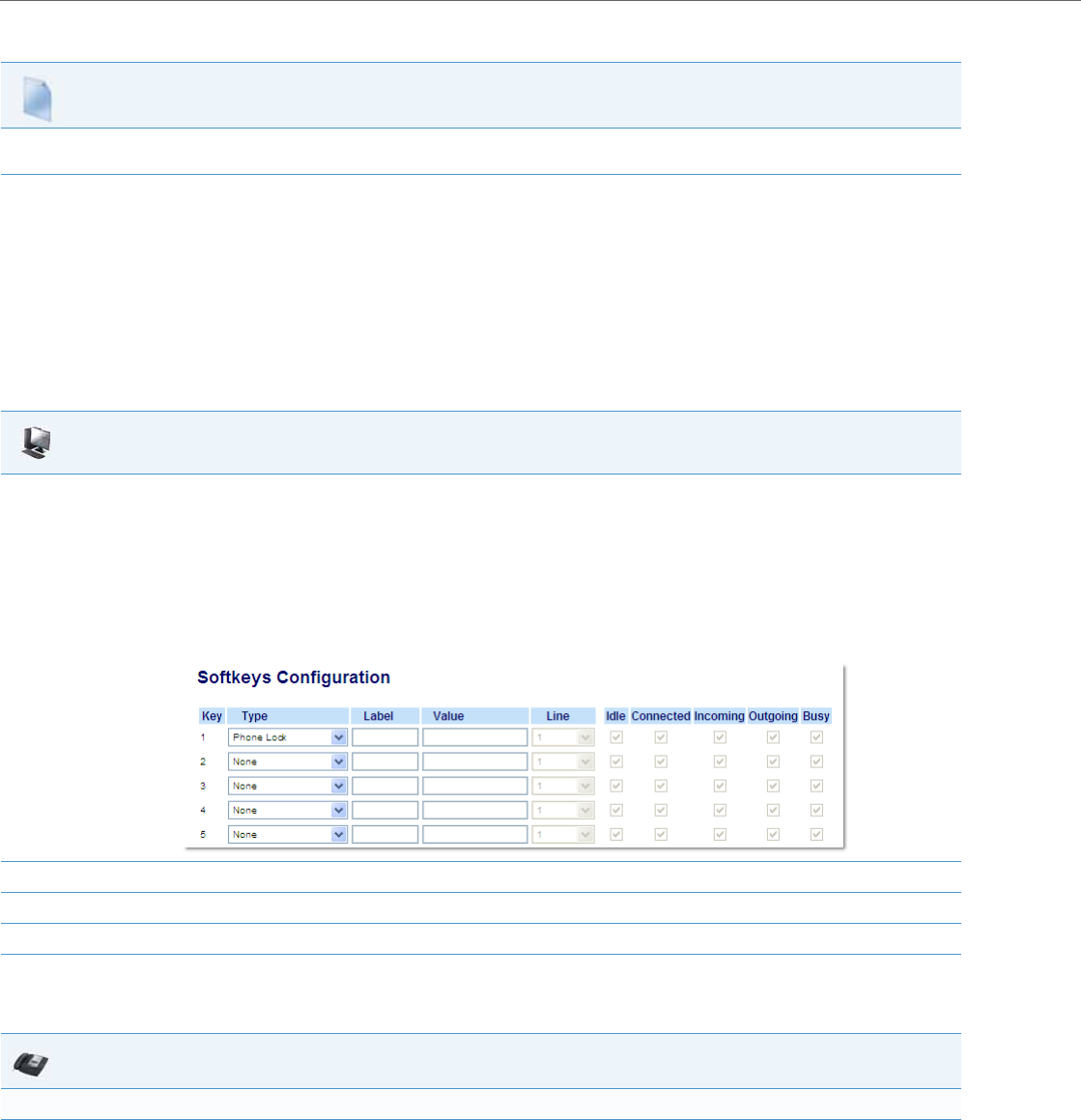
Operational Features
5-10 41-001343-02 REV04 – 05.2014
Use the following procedure to configure a key as a lock/unlock key using the configuration files.
Reference
To use the lock/unlock softkey or programmable key, see “Using the Configured Lock/Unlock Softkey on the IP Phone”
on page5-10.
Configuring a Lock/Unlock Softkey using the Aastra Web UI
Using the Aastra Web UI, you can configure a softkey on the phone (softkey, programmable key, expansion module key)
to use as a lock/unlock key. In the Aastra Web UI, you assign the function of the softkey as “Phone Lock”.
Use the following procedure to configure a key as a lock/unlock key using the Aastra Web UI.
Using the Configured Lock/Unlock Softkey on the IP Phone
After configuring a key as a lock/unlock key, refer to the following procedure to use the key on the IP phone.
Configuration Files
To configure a softkey/programmable key as a lock/unlock key using the configuration files, see Appendix A, the section, “Softkey/Programmable
Key/Keypad Key/Feature Key/Expansion Module Key/Hard Key Parameters” on pageA-156.
Aastra Web UI
1. Click on Operation->Softkeys and XML
or
Click on Operation->Programmable Keys
or
Click on Operation->Expansion Module <N>.
Note:
Depending on your phone-model, the key configuration screen displays. The 6755i Softkey Configuration Screen is shown as an example.
2. Select a key you want to configure for locking/unlocking the phone.
3. In the “Type” field, select Phone Lock from the list of options.
4. Click Save Settings to save your changes.
IP Phone UI
Lock the phone:
1. Press the LOCK softkey.
The phone locks.
The LED for the softkey AND the Message Waiting Lamp illuminate steady ON.
An “Unlock” label appears next to the softkey you just pressed.

Operational Features
41-001343-02 REV04 – 05.2014 5-11
For the 6739i:
For the 6867i:
Unlock the phone:
1. Press the UNLOCK softkey.
A password prompt displays.
2. Enter the user or administrator password and press ENTER.
The phone unlocks.
The LED for the softkey AND the Message Waiting Lamp go OFF.
The “Lock” label appears next to the softkey you just pressed.
IP Phone UI
Lock the phone:
1. Press the LOCK softkey. The phone locks.
The message “Phone is Locked” displays on the screen.
The LED for the softkey AND the Message Waiting Lamp illuminate steady ON.
Unlock the phone:
1. Press the UNLOCK key. The “Unlock” key has a steady ON LED.
A password prompt displays.
2. Enter the user or administrator password and press Enter. Default is “22222”.
A prompt “Unlock the Phone?” displays.
3. Press Ye s to unlock the phone.
The phone unlocks.
IP Phone UI
Lock the phone:
1. Press the LOCK softkey. The phone locks.
The message “Phone is Locked” displays on the screen.
The LED for the softkey (if applicable) AND the Message Waiting Lamp illuminate steady ON.
Unlock the phone:
1. Press the UNLOCK softkey.
A password prompt displays.
2. Enter the user or administrator password and press the button or Enter softkey. Default is “22222”.
A prompt “Unlock the Phone?” displays.
3. Press Ye s to unlock the phone.
The phone unlocks.
IP Phone UI

Operational Features
5-12 41-001343-02 REV04 – 05.2014
Defining an Emergency Dial Plan
Public telephone networks in countries around the world have a single emergency telephone number (emergency serv-
ices number), that allows a caller to contact local emergency services for assistance when required. The emergency tele-
phone number may differ from country to country. It is typically a three-digit number so that it can be easily remem-
bered and dialed quickly. Some countries have a different emergency number for each of the different emergency serv-
ices.
You can specify the digits to dial on the IP phone for contacting emergency services. Once you specify the emergency
number(s) on the phone, you can dial those numbers directly on the dial pad when required and the phone automati-
cally dials to those emergency services.
The following table describes the default emergency numbers on the IP phones.
Emergency Dial Plan and Pattern Matching
The IP Phones support emergency dialing using pattern matching and prepend dial plan functionality.
There are two ways to dial a number on the phone:
•dialing digit-by-digit (i.e., select line and dial)
•dialing by string (i.e., pre-dial then go off-hook)
When a user dials digit-by-digit, the phone adds every digit to a dialed string and checks against the dial plan. If the
phone is not locked, it checks against the regular dial plan. If the phone is locked, it checks against the emergency dial
plan.
When a user dials by string, (pre-dial, speed-dial, etc., and then goes off-hook), and the phone is not locked, it checks to
see if the number matches the emergency dial plan. If it doesn’t match, it blocks the call from going through. If the
phone is locked, and the number matches the emergency dial plan it allows the call to go through.
Adding a prepend to a dial plan also works with both dialing digit-by-digit and dialing by string.
Limitation
The following is a limitation for emergency dial plans with pattern matching:
•Secondary dial tone is not supported.
You can set the emergency dial plan via the configuration files or the Aastra Web UI.
Configuring an Emergency Dial Plan
Use the following procedures to specify the numbers to use on your phone for dialing emergency services in your area.
Note:
Contact your local phone service provider for available emergency numbers in your area.
Emergency Number Description
911 A United States emergency number
999 A United Kingdom emergency number
112 An international emergency telephone number for GSM mobile phone networks.
In all European Union countries it is also the emergency telephone number for both mobile and fixed-line tele-
phones.
110 A police and/or fire emergency number in Asia, Europe, Middle East, and South America.
Configuration Files
For specific parameters you can set in the configuration files, see Appendix A, the section, “Emergency Dial Plan Settings” on pageA-15.
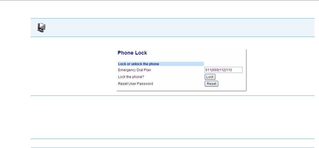
Operational Features
41-001343-02 REV04 – 05.2014 5-13
Aastra Web UI
1. Click on Operation->Phone Lock.
2. In the “Emergency Dial Plan” field, enter the number used in your local area to contact emergency services. For multiple numbers, enter a
“|” between each emergency number.
For example:
911|110.
Default for this field is "911|999|112|110". You can enter up to 512 characters in this field.
3. Click Save Settings to save the emergency dial plan to your phone.

Operational Features
5-14 41-001343-02 REV04 – 05.2014
Configurable Emergency Call Behavior
Administrators have the option of changing the default behavior of the IP phones when an emergency call (i.e. a call
made to an emergency number matching one of the values defined in the “emergency dial plan” parameter) is placed.
If the “emergency call connection hold enabled“ configuration parameter is enabled, the IP phones employ the follow-
ing behaviors:
•Connection Hold: If an emergency call is placed, the IP phones ensure the voice/audio path and other resources asso-
ciated with the emergency call are continually active, even if the caller hangs up the phone (i.e. the handset is placed
on-hook).
–If the handset is placed on-hook, the phone automatically switches to speakerphone mode ensuring that the call is
still active. Alternatively, if the handset is taken off-hook, the phone automatically switches to handset mode.
–All softkey and hardkey events (e.g. hold, conference, transfer, end call, park, mute, etc...) are disabled as they may
impede or be disruptive to the active call.
–The phone does not allow for the origination or termination of any call while the phone is connected to the emer-
gency services agent. All incoming calls and pages are ignored and a busy tone is presented to the remote caller.
•Enhanced Called Party Hold: As a complement to the Connection Hold feature, Enhanced Called Party Hold allows
the voice/audio path to be established the moment the emergency call is placed.
–When a caller places a call to an emergency services number, all Connection Hold features are activated, even if the
SIP session has not been established completely.
–Even if the caller abandons the call before the emergency services agent answers, the voice/audio path and Con-
nection Hold features will still be active.
•Forced Disconnect: As the Connection Hold feature ensures that the caller cannot terminate the call, the only way
the call can be terminated is if the emergency services agent forces the disconnection by ending the call himself/her-
self.
The “emergency call connection hold enabled“ parameter is disabled by default.
Configuring Emergency Call Behavior
Use the following procedures to configure the IP phone’s behavior when emergency calls are placed.
User Dial Plan Setting
The IP Phones have a parameter for configuring a dial plan that distinguishes between calling a real PSTN number and a
number that looks like a PSTN number but is actually on an IP network.
This parameter is “sip user parameter dial plan”. Using the configuration files, an Administrator can configure a dial plan
corresponding to a IP network number (i.e. 6xx|8xxxx|9xxxxxxx) that the phone checks before sending the SIP packet.
If for example, the number that was dialed was 645, the phone checks the dial plan and matches the number to the dial
plan (6xx in the example above), before sending out the SIP packet. The SIP packet header omits the user parameter
user=ip (i.e. “To: <sip:645@10.30.102.24:10060>“) identifying the number as one from an IP network. If the number that
was dialed was 456-2345, the phone tries to match the number to the dial plan before sending out the SIP packet but as
it is not part of the dial plan the phone identifies the number as a PSTN number. The SIP packet header in this case indi-
cates user=phone (i.e., “To: <sip:4562345:10060;user=phone>“).
Configuration Files
For specific parameters you can set in the configuration files, see Appendix A, the section, “Emergency Call Behavior Settings” on pageA-15.
Note:
•Entering a dial plan value for this parameter enables this feature. Entering no value for this parameter in the config-
uration files, disables this feature.
•You can configure the “sip user parameter dial plan” parameter on a global basis only. If it is misconfigured, then
the parameter is ignored.

Operational Features
41-001343-02 REV04 – 05.2014 5-15
Configuring the SIP User Parameter Dial Plan
Use the following procedure to configure the SIP user parameter dial plan.
Limitation
The “sip user parameter dial plan” value is checked AFTER an existing prepend dial plan is checked, so the number that
the phone dials will have prepend digits also.
Time and Date
In addition to enabling/disabling the time server, you can also set the time and date format, set the time zone, and set day-
light savings time on the IP phones. You configure these features using the configuration files, the IP Phone UI, or the Aas-
tra Web UI. The following table identifies which method of configuration applies to each feature.
Daylight Savings Time (DST) Information
The Aastra IP Phones incorporate the federally mandated DST observance change. This change became affective starting
in 2007.
The US has made a change to its daylight savings time observance starting in 2007. The Energy Policy Act of 2005 man-
dates that DST will now begin at 2:00 A.M. on the second Sunday in March and revert to Standard time on the first Sunday
in November.
The changes to daylight savings time applies to the U.S. and Canada, but may impact other countries outside North Amer-
ica.
Time Zone & DST
There are two ways you can set the time zone on the IP Phones.
Configuration Files
For the specific parameter you can set in the configuration files, see Appendix A, the section, “User Dial Plan Setting” on pageA-16.
Feature Method of configuration
Set Time Format Configuration Files
IP Phone UI
Aastra Web UI
Set Date Format Configuration Files
IP Phone UI
Aastra Web UI
Set Time Zone IP Phone UI
Configuration Files
Set Daylight Savings Time IP Phone UI
Configuration Files
Note:
In previous years, the DST began on the first Sunday of April and ended on the first Sunday of October.
Note:
DST can be set on the phones using the IP Phone UI and configuration files only. For more information, see “Time Zone
& DST” on page5-15.

Operational Features
5-16 41-001343-02 REV04 – 05.2014
Method 1
You can set a time zone using the Time Zone option in the IP Phone UI or you can use the “time zone name” parameter
in the configuration files. Both methods allow you to enter a value from the Time Zone table. The list of time zone names
is provided in the table in Appendix A, the section, “Time Zone Name/Time Zone Code Table” on pageA-42. The follow-
ing is an example:
time zone name: US-Eastern
Method 2
You can use the Time Zone option in the IP Phone UI or your can use the “time zone name” parameter in the configura-
tion files, and specify a value of “Custom” for this parameter (must use initial caps). The “Custom” option allows you to
customize the time zone for your area using additional configuration parameters. The following is an example using rel-
ative time for EST:
time zone name: Custom
The following table identifies the additional time zone and DST parameters you can enter in the configuration files.
Custom Configuration
File Parameter Description Example
time zone minutes The number of minutes the time zone is offset from UTC
(Coordinated Universal Time). This can be positive (West of
the Prime Meridian) or negative (East of the Prime Merid-
ian). The default is Eastern Standard Time (EST) with a value
of 300 (GMT minus 5 hours).
time zone minutes: 300
For additional values for this parameter, see
“Custom Time Zone and DST Settings” on
pageA-47.
dst minutes The number of minutes to add during Daylight Saving Time.
Valid values are a positive integer between 0 to 60. dst minutes: 60
dst [start|end] relative date Specifies how to interpret the start and end day, month, and
week parameters - absolute (0) or relative (1). dst [start|end] relative date: 1
Absolute Time (not applicable to Eastern Standard Time (EST))
dst start month The month that DST starts. Valid values are 1 to 12 (January
to December). dst start month: 3
dst end month The month that DST ends. Valid values are 1 to 12 (January
to December). dst end month: 4
dst [start |end] week Not applicable to absolute time. N/A
dst start day The day of the month that DST starts. Valid values are 1 to
31. dst start day: 15
dst end day The day of the month that DST ends. Valid values are 1 to 31. dst end day: 31
dst start hour The hour that DST starts. Valid values are an integer from 0
(midnight) to 23. dst start hour: 5
dst end hour The hour that DST ends. Valid values are an integer from 0
(midnight) to 23. dst end hour: 23
Relative Time
dst start month The month that DST starts. Valid values are 1 to 12 (January
to December). dst start month: 4
dst end month The month that DST ends. Valid values are 1 to 12 (January
to December). dst end month: 5

Operational Features
41-001343-02 REV04 – 05.2014 5-17
Example 1
The following is an example of a custom time zone configuration in the configuration files using relative time (for EST):
time zone name: Custom
dst [start|end] relative date: 1 #relative
time zone minutes: 300
dst minutes: 60
dst start week The week in the specified month in which DST starts. Valid
value is a positive or negative integer from 1 to 5.
1 = first full week of month
-1 = last occurrence "dst start day" in the month
2 = second full week of month
-2 =second last occurrence "dst start day" in the month
.
.
.
5 = fifth full week of month
-5 = fifth last occurrence "dst start day" in the month
dst start week: 2
dst end week The week in the specified month in which DST ends. Valid
value is a positive or negative integer from 1 to 5.
1 = first full week of month
-1 = last occurrence "dst start day" in the month
2 = second full week of month
-2 =second last occurrence "dst start day" in the month
.
.
.
5 = fifth full week of month
-5 = fifth last occurrence "dst start day" in the month
dst end week: -1
dst start day The day of the specified week in the specified month that
DST starts on. Valid values are an integer from 1 to 7.
1 = Sunday
2 = Monday
.
.
.
7 = Saturday
dst start day: 2
dst end day The day of the specified week in the specified month that
DST ends on. Valid values are an integer from 1 to 7.
1 = Sunday
2 = Monday
.
.
.
7 = Saturday
dst end day: 7
dst start hour The hour that DST starts. Valid values are an integer from 0
(midnight) to 23. dst start hour: 10
dst end hour The hour that DST ends. Valid values are an integer from 0
(midnight) to 23. dst end hour: 23
Custom Configuration
File Parameter Description Example

Operational Features
5-18 41-001343-02 REV04 – 05.2014
Example 2
The following is an example of a custom time zone configuration in the configuration files using absolute time:
time zone name: Custom
dst [start|end] relative date: 0 #absolute
#start of DST
dst start month: 3 #March
dst start week: 2 #second full week
dst start day: 1 #Sunday
#End of DST
dst end month: 11 #November
dst end week: 1 #first full week
dst end day: 1 #Sunday
DHCP Time Offset (Option 2) Support
DHCP Option 42 enables the phone to be configured with the Network Time Protocol (NTP) server addresses. However,
NTP provides the Coordinated Universal Time (UTC) time so the phone requires the offset from UTC in order to deliver
the correct local time.
A User or Administrator can set the offset of UTC using DHCP Option 2.
An Administrator can enable Option 2 in the configuration files by setting the parameter “time zone name”. I f t h i s
parameter contains the DP-Dhcp value, the phone derives the time and date from UTC and the time offset offered by the
DHCP server.
Using the IP Phone UI, a User or Administrator can enable the phone to use DHCP Option 2 by setting the following val-
ues from the Country Code list on the phone:
On the IP Phone UI for 8 and 11-line phones, a User or Administrator can select Preferences->Time and Date->Time
Zone->Others and choose “DP-Dhcp” from the displayed time zone list.
On the IP Phone UI for 3-line phones, you select Preferences->Time and Date->Time Zone->Others and enter “DP” for
the country code, or press “*” and select “Dhcp” from the displayed time zone list.
On the 6739i, a User or Administrator can select Set Time->Timezone->Others and choose “DP-Dhcp” from the dis-
played time zone list.
If you enable DHCP Option 2 via the IP Phone UI, the change takes place dynamically.
References
For more information about setting DP-DHCP for the timezone, see Appendix A, “Time Zone Name” on pageA-41.
For more information about setting the country code, see Appendix A, “Country Codes (from Standard ISO 3166)” on
pageA-138.
Country Name Country Code
Dhcp DP
Note:
The country name, country code, and time zone name are case sensitive.
Notes:
•When DHCP Option 2 is enabled on the phone, the phone still uses the values configured for Daylight Savings to
control daylight savings time.
•The default behavior for the phone is to use the NTP server from Option 42 (or current configuration setting) and the
current time zone settings.
•If the time zone name parameter is set to a value other than Dhcp, then DHCP Option 2 is disabled.
Operational Features
41-001343-02 REV04 – 05.2014 5-19
Custom Time Zone Support
A User or Administrator can also set a custom time zone on the phone to be configured with the Network Time Protocol
(NTP) server addresses. However, NTP provides the Coordinated Universal Time (UTC) time so the phone requires the offset
from UTC in order to deliver the correct local time.
On the IP Phone UI for 8 and 11-line phones, a User or Administrator can select Preferences->Time and Date->Time Zone-
>Others and choose “Custom” from the displayed time zone list.
On the IP Phone UI for 3-line phones, you select Preferences->Time and Date->Time Zone->Others and enter “Custom”
for the country code.
On the 6739i, a User or Administrator can select Set Time->Timezone->Others and choose “Custom” from the displayed
time zone list.
References
For more information about setting a custom timezone, see Appendix A, “Time Zone Name” on pageA-41.
Configuring Time and Date Using the Configuration Files
Use the following information to set a time and date format, time zone, and daylight savings time using the configuration
files.
Configuring Time and Date Using the IP Phone UI
Use the following procedure to set a time and date, time and date format, time zone, and daylight savings time using the
IP Phone UI.
Configuration Files
For specific date and time parameters you can set in the configuration files, see Appendix A, the section, “Time and Date Settings” on pageA-40.
For specific parameters you can set for custom time zone settings, see Appendix A, the section, “Custom Time Zone and DST Settings” on pageA-47.
IP Phone UI
1. Press on the phone to enter the Options List.
Set Time Format:
2. Select Time and Date.
3. Select Time Format.
Valid values are 12 Hour and 24 Hour.
Note:
The default Time Format is 12 Hour.
4. Use the navigation keys to select the preferred time format.
5. Press Done to save the Time Format you selected.
Set Date Format:
6. Select Date Format.

Operational Features
5-20 41-001343-02 REV04 – 05.2014
7. Select a date format from the list of options.
Valid values are:
•WWW MMM DD (default)
•DD-MMM-YY
•YYYY-MM-DD
•DD/MM/YYYY
•DD/MM/YY
•DD-MM-YY
•MM/DD/YY
•MMM DD
•DD MMM YYYY
•WWW DD MMM
•DD MMM
•DD.MM.YYYY
Note:
The default Date Format is WWW MMM DD (Day of Week, Month, Day).
8. Press Done to save the Date Format.
Set Time Zone:
9. Select Time Zone.
10. For 3-Line LCD Displays:
Press * to display a list of time zones.
For 8 and 11-Line LCD Displays:
Use the navigation keys to view available time zones.
Note:
For more information about setting the time zone to “DP-Dhcp” or “Custom”, see “DHCP Time Offset (Option 2) Support” on page5-18, “Cus-
tom Time Zone Support” on page5-19, or Appendix A, “Time Zone Name” on pageA-41.
11. Select a Time Zone from the list of values.
For valid values, see Appendix A, the section, “Time and Date Settings” on pageA-40.
Note:
The default Time Zone is US-Eastern.
12. Press Done to save the Time Zone you selected.
Set Daylight Savings Time:
13. Select Daylight Savings.
14. Select a Daylight Savings time from the list of options.
Valid values are:
•OFF
•30 min summertime
•1 hr summertime
•automatic
Note:
The default for Daylight Savings is Automatic.
15. Press Done to save the Daylight Savings value you selected.
IP Phone UI

Operational Features
41-001343-02 REV04 – 05.2014 5-21
For the 6739i:
IP Phone UI
1. Press the Options key on the phone to enter the Options List.
Set Time Format:
2. Press Set Time.
3. Press Time Format and select a value for the time format on your phone.
Valid values are 12 Hour and 24 Hour.
Note:
The default Time Format is 12 Hour.
Set Date Format:
4. Press Date Format.
5. Select a date format from the list of values.
Valid values are:
•WWW MMM DD (default)
•DD-MMM-YY
•YYYY-MM-DD
•DD/MM/YYYY
•DD/MM/YY
•DD-MM-YY
•MM/DD/YY
•MMM DD
•DD MMM YYYY
•WWW DD MMM
•DD MMM
•DD.MM.YYYY
Note:
The default Date Format is WWW MMM DD (Day of Week, Month, Day).
Set Time Zone:
6. Press Time Zone.
7. Press a country. Valid values are:
•America
•Asia
•Atlantic
•Australia
•Europe
•Pacific
•Others (DP-Dhcp, Custom)
Note:
For more information about setting the time zone to “DP-Dhcp” or “Custom”, see “DHCP Time Offset (Option 2) Support” on page5-18, “Cus-
tom Time Zone Support” on page5-19, or Appendix A, “Time Zone Name” on pageA-41.
8. Press a Time Zone from the list of values.
For valid values, see Appendix A, the section, “Time and Date Settings” on pageA-40.
The default Time Zone is US-Eastern.
9. Press the to return to the previous screen.
Operational Features
5-22 41-001343-02 REV04 – 05.2014
Set Daylight Savings Time:
10. Press Daylight Savings.
11. Press a Daylight Savings time option.
Valid values are:
•OFF
•30 min summertime
•1 hr summertime
•automatic
Note:
The default for Daylight Savings is Automatic.
12. Press the to return to the previous screen.
13. Press the button or the button at any time to return to the idle screen.
IP Phone UI

Operational Features
41-001343-02 REV04 – 05.2014 5-23
For the 6867i:
IP Phone UI
1. Press to enter the Options List.
Set Time Format:
2. Navigate to the Time and Date -> Settings option and press the button or Select softkey.
3. With Time Format highlighted press the 4 key to move to selection column.
4. Use the 5 and 2 keys to scroll through and choose the desired time format. Valid values are 12 Hour and 24 Hour (the default is 12 Hour).
Set Daylight Savings:
5. Press the 3 key to move to back to the options column and press the 4 key to highlight Daylight Savings.
6. With Daylight Savings highlighted press the 4 key to move to selection column.
7. Use the 5 and 2 keys to scroll through and choose the desired daylight savings setting. Valid values are:
•Off
•30 min summertime
•1h summertime
•Automatic (default)
Set Date Format:
8. Press the 3 key to move to back to the options column and press the 4 key to highlight Date Format.
9. With Date Format highlighted press the 4 key to move to selection column.
10. Use the 5 and 2 keys to scroll through and choose the desired date format. Valid values are:
•WWW MMM DD (default)
•DD-MMM-YY
•YYYY-MM-DD
•DD/MM/YYYY
•DD/MM/YY
•DD-MM-YY
•MM/DD/YY
•MMM DD
•DD MMM YYYY
•WWW DD MMM
•DD MMM
•DD.MM.YYYY
11. Press the Save softkey to save your changes.
Set Daylight Savings Time:
12. Navigate to the Time and Date -> Time Zone option and press the button or Select softkey.
A list of time zones displays for different areas of the world.
13. Use the 5 and 2 keys to scroll through and highlight the desired region. Valid values are:
•America
•Asia
•Atlantic
•Australia
•Europe
•Pacific
•Others
14. With the desired region highlighted press the 4 key to move to selection column.
15. Use the 5 and 2 keys to scroll through and choose the time zone that applies to your area. The default time zone is US-Eastern.
16. Press the Save softkey to save your changes.
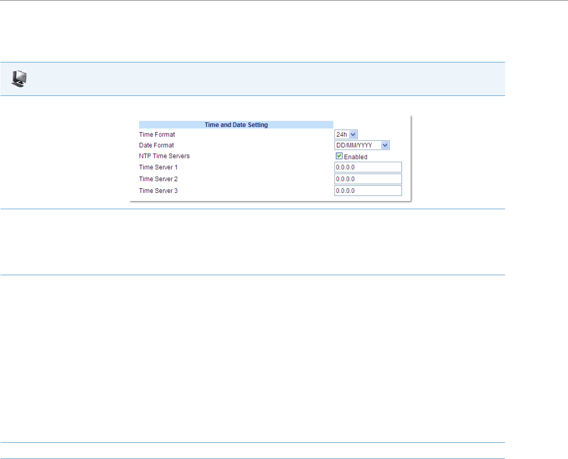
Operational Features
5-24 41-001343-02 REV04 – 05.2014
Configuring Time and Date Using the Aastra Web UI
Use the following procedure to set a time and date, time and date format, time zone, and daylight savings time using the
Aastra Web UI.
Time Servers
A time server is a computer server that reads the actual time from a reference clock and distributes this information to
the clients in a network. The time server may be a local network time server or an internet time server. The Network Time
Protocol (NTP) is the most widely used protocol that distributes and synchronizes time in the network with the time on
the time server.
On the IP phones, you can enable or disable a Time Server to be used to synchronize time on the phones with the Timer
Server you specify. An Administrator can use the IP Phone UI, Aastra Web UI, or configuration files to enable/disable the
Time Server and specify a Time Server 1, Timer Server 2, and/or Time Server 3. A User can enable/disable the Time Server
using the IP Phone UI or Aastra Web UI only. The Time Server is enabled by default.
Aastra Web UI
1. Click on Basic Settings->Preferences->Time and Date Setting.
2. In the “Time Format” field, select the time format you want to use on your phone. Valid values are:
•12h (12 hour format) (default)
•24h (24 hour format).
Note:
The time displays on the phone’s idle screen in the format you select for this field.
3. In the “Date Format” field, select the date format you want to use on your phone. Valid values are:
•WWW MMM DD (default)
•DD-MMM-YY
•YYYY-MM-DD
•DD/MM/YYYY
•DD/MM/YY
•DD-MM-YY
•MM/DD/YY
•MMM DD
•DD MMM YYYY
•WWW DD MMM
•DD MMM
•DD.MM.YYYY
Note:
The date displays on the phone’s idle screen in the format you select for this field.
4. Click Save Settings to save your changes.
Operational Features
41-001343-02 REV04 – 05.2014 5-25
Setting Time Server Using the Configuration Files
Use the following procedure to enable/disable the Time Server and optionally set the IP Address of Time Servers 1, 2,
and/or 3.
Setting Time Server Using the IP Phone UI
Use the following procedure to set the Time Server and optionally set the IP Address of Time Servers 1, 2, and/or 3.
Configuration Files
For specific parameters you can set in the configuration files, see Appendix A, the section, “Time Server Settings” on pageA-45.
IP Phone UI
Enable/the Time Server by specifying Time Server 1, 2, and/or 3:
1. Press on the phone to enter the Options List.
2. Select Preferences->Time and Date.
3. Select Timer Server 1, Time Server 2, and/or Time Server 3.
4. Enter the IP address of the Time Server, in dotted decimal format. Use the available softkeys to help you enter the information.
5. Click Done to save your changes.
For the 6739i:
1. Press on the phone to enter the Options List.
2. Press Set Time.
3. Press Timer Server 1, Time Server 2, and/or Time Server 3. A text box displays.
4. Press the text box and enter the IP address of the Time Server, in dotted decimal format using the keyboard that displays.
5. Press Enter to save your changes.
6. Press the to return to the previous screen.
7. Press the button or the button at any time to return to the idle screen.
For the 6867i:
1. Press to enter the Options List.
2. Select Time and Date -> Set Date and Time.
3. Ensure there is a checkmark in the box corresponding to the Use Network Time setting. If there is no checkmark, press the button to
enable the Use Network Time setting.
4. Press the 2 key to highlight Time Server 1, Time Server 2, or Time Server 3.
5. Using the keys on the dialpad, enter an IP address or domain name for the time server.
6. Press the Save softkey to save your changes.
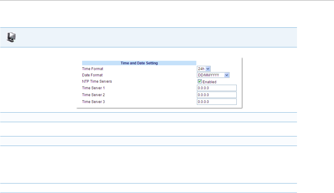
Operational Features
5-26 41-001343-02 REV04 – 05.2014
Setting Time Server Using the Aastra Web UI
Use the following procedure to set the Time Server and optionally set the IP Address of Time Servers 1, 2, and/or 3.
Aastra Web UI
1. Click on Basic Settings->Preferences->Time and Date Setting.
To enable/disable Time Server:
2. The “NTP Time Server” field is enabled by default. If you need to disable the Time Server, uncheck the box. The Time Server 1, 2, and 3 fields
are grayed out when disabled.
To set Time Server 1, 2, and/or 3:
3. Note:
The “Time Server” field must be enabled to enter values in the “Time Server 1, 2, and 3” fields.
In the “Time Server 1”, “ Time Server 2”, and/or “Time Server 3” field(s), enter the IP address of the Time Server 1, 2, and/or 3 in your net-
work, in dotted decimal format. Default for this field is 0.0.0.0.
For example, 132.234.5.4
4. Click Save Settings to save your changes.
Operational Features
41-001343-02 REV04 – 05.2014 5-27
Backlight Mode
The 6735i, 6737i, 6755i, 6757i, 6757i CT and 6865i have a backlight feature that allows you to turn the backlight on the
LCD:
•Off - Backlight is always OFF.
•Auto (Default)- Automatically turns ON the backlight when the phone is in use, and then automatically turns OFF the
backlight when the phone is idle after a specified length of time.
“The Auto” setting sets the phone to turn off the backlighting after a period of inactivity. The period of time that the phone
waits before turning the backlight off is also configurable.
You can set this backlight feature using the configuration files and the IP Phone UI.
Configuring the Backlight Mode Using the Configuration Files
Use the following information to set the backlight mode and backlight timer on the IP Phones.
Configuring the Backlight Mode Using the IP Phone UI
Use the following procedure to set the backlight mode and backlight timer on the IP Phone using the IP Phone UI.
Note:
Applicable to the 6735i, 6737i, 6755i, 6757i, 6757i CT, and 6865i IP Phones only.
Configuration Files
For specific parameters you can set in the configuration files, see Appendix A, the section, “Backlight Mode Settings” on pageA-53.
Note:
Using the configuration files, you can set the backlight to Off (always off) or Auto (On and then off after a period of inactivity).
IP Phone UI
1. Press on the phone to enter the Options List.
2. Select Preferences.
3. Select Display.
4. Select Backlight.
5. Use the UP and DOWN arrow keys to select the Backlight status for your phone.
Default is “Auto”. Valid options are:
•Off
•Auto (Default)
Note:
Setting the Backlight to “Auto” displays an ADVANCED button for you to set the Auto timer.
6. If you select “Off”, press Done to save your setting.
7. If you select “Auto”, press the Advanced softkey to set the automatic timer.
8. Using the keypad, enter the amount of seconds you want the phone to stay backlit when the phone is idle. Valid values are 1 to 7200 sec-
onds. Default is 600 seconds (equals 10 minutes). When this period of time is reached, the phone turns OFF the backlight. Use the "Back-
space" and/or "Clear" softkeys to delete entries if required.
9. Press Done to save your setting. The setting applies immediately to the phone.
Operational Features
5-28 41-001343-02 REV04 – 05.2014
Display
The Display option on the 6739i and 6867i IP phones allows you to set the following on your phone:
•Brightness Level
•Brightness Timer
•Calibrate Screen (6739i only)
Brightness Level
The "Brightness Level" option allows you to set the amount of light that illuminates the LCD display. Use this option to
set your preference of brightness.
Setting Brightness
For the 6739i:
For the 6867i:
Note:
Applicable to the 6739i and 6867i IP Phones only.
IP Phone UI
1. Press on the phone to enter the Options List
2. Press the <Display> button.
3. Press the <Brightness Level> button. The following options display.
•Level 1
•Level 2
•Level (default)3
•Level 4
•Level 5
4. Press the level of brightness you want on your phone. Level 1 is the least bright and Level 5 is the most bright. Default is Level 3.
5. Press the to return to the previous menu or press the to return to the idle screen.
IP Phone UI
1. Press to enter the Options List.
2. Navigate to the Display option and press the button or Select softkey.
3. Use the3 and 4 navigation buttons to increase or decrease the intensity of brightness on the LCD.
4. Press the Save softkey to save your changes.
Operational Features
41-001343-02 REV04 – 05.2014 5-29
Brightness Timer
The "Brightness Timer" option allows you to set the amount of time you want the LCD display to stay illuminated before
turning the backlight off during a period of inactivity. For example, if you set the brightness timer to 60, when the phone
reaches 60 seconds of inactivity, the LCD backlight goes off.
Setting Brightness Timer
For the 6739i:
For the 6867i:
Configuring the Brightness Level Settings Using the Configuration Files
Use the following information to configure the brightness level settings on the 6739i and 6867i.
IP Phone UI
1. Press on the phone to enter the Options List
2. Press the <Display> button.
3. Press the <Brightness Timer> button. A text box displays.
4. Press the text box. A pop-up keyboard displays.
5. Press the “123” key and enter a value, in seconds, for the Brightness Timer. You can set the Brightness Timer from 0 to 7200 seconds. Default
is 600 (10 minutes).
6. Press the to return to the previous menu or press the to return to the idle screen.
IP Phone UI
1. Press to enter the Options List.
2. Navigate to the Display option and press the button or Select softkey.
3. Press the 2 key to highlight Brightness Timer.
4. Enter a value, in seconds, using the dialpad keys. You can set the timer from 1 to 7200 seconds. Default is 600 (10 minutes).
5. Press the Save softkey to save your changes.
Configuration Files
For specific parameters you can set in the configuration files, see Appendix A, the section, “Brightness Level Settings” on pageA-54.
Operational Features
5-30 41-001343-02 REV04 – 05.2014
Calibrate Screen (6739i only)
The “Calibrate Screen” option allows you to calibrate the color touchscreen. This process makes fine adjustments to the
color screen on the phone for optimal display purposes.
Calibrating the Screen
Background Image on Idle Screen
Administrators can brand the idle screen of the 6739i and 6867i IP phones with their own company logo or image. The
phones can now display a background image in the bottom layer of the idle screen. This image can be set by the new
“background image” parameter. Current text (i.e. screen name, extension, and date/time) and softkeys on the idle
screen are on top of the background image. The background image can be downloaded from your configuration server
using either tftp, ftp, http, and https protocols.
Idle Screen Image Requirements for the 6739i:
•640 x 480 pixels
•24-bit color depth
•Both .png and .jpg files are supported
•There should be no frame around the image
•Avoid using images with light-colored elements
IP Phone UI
1. Press on the phone to enter the Options List
2. Press the <Display> button.
3. Press the <Calibrate Screen> button.
A “Recalibrate touchscreen?” prompt displays.
4. Press “Yes” to continue or “No” to cancel the recalibration.
5. If you press “Yes”, the following messages display:
“Waiting for touchscreen activity to subside....”
6. Press the screen as indicated by each prompt using a SOFT fine tip stylus pen. Do not use a sharp object such as an ink pen or pencil which
may damage the touch screen.:
“Touch the UPPER-LEFT corner of the screen.”
“Touch the UPPER-RIGHT corner of the screen.”
“Touch the LOWER-RIGHT corner of the screen.”
“Touch the LOWER-LEFT corner of the screen.”
If you touched the screen in the wrong location, the following message displays:
“Received unreliable data. You will be asked to touch the same point again.”
Retouch the screen in the correct location to continue.
The following message displays:
“Validating calibration data....please wait.”
Then the following message and prompt displays:
“Sanity Check OK. Save changes?”
7. Press the Yes button to complete the recalibration, and the phone automatically restarts.
Note:
Applicable to the 6739i and 6867i IP Phones only.
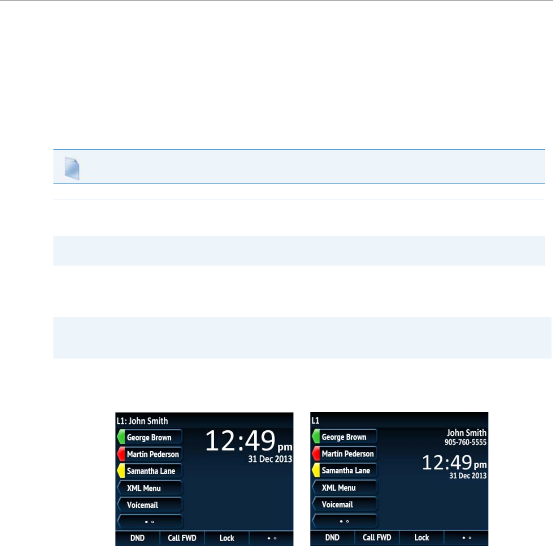
Operational Features
41-001343-02 REV04 – 05.2014 5-31
Idle Screen Image Requirements for the 6867i:
•240x320 pixels
•24-bit color depth.
•.png files only are supported
•There should be no frame around the image
•Avoid using images with light-colored elements
Configuring Background Image on Idle Screen
Use the following procedures to configure the background image on the idle screen
Configurable Home/Idle Screen Modes
The 6867i IP phone contains two Home/Idle screen layout options. The default primary screen mode provides users with a
larger date and time and displays the Screen Name (“sip screen name”) parameter beside the line number in the top sta-
tus bar.
The secondary screen mode displays both the Screen Name and Screen Name 2 parameters. They are displayed above the
smaller, repositioned date and time.
Administrators can switch the home/idle screen to the preferred layout by defining the “idle screen mode” parameter in
the configuration files.
Configuration Files
For specific parameters you can set in the configuration files, see Appendix A, the section, “Background Image on Idle Screen” on pageA-55.
Note:
Applicable to the 6867i IP Phone only.
Note:
Screen Name 2 (“sip screen name 2”) is not displayed on the 6867i IP phone’s screen when the primary screen mode is
configured for use.
Primary Home/Idle Screen Mode Secondary Home/Idle Screen Mode

Operational Features
5-32 41-001343-02 REV04 – 05.2014
Switching the 6867i IP Phone’s Home/Idle Screen Mode
Use the following procedures to switch the 6867i IP phones home/idle screen mode.
Picture ID Feature
The Picture ID feature on the 6739i and 6867i shows a picture ID of a caller on the LCD for all of the following events on
the phone:
•Incoming Calls (matched to Caller ID numbers)
•Outgoing Calls (matched to dialed numbers)
•Directory entries
•Callers List entries
•Redial List entries
Your Administrator stores the pictures in a centralized picture repository. The pictures are dynamically retrieved from the
centralized server for each call and then locally cached in the phone to reduce network traffic.
If there is no picture on the central server for the dialed number and/or Caller Id number, and Directory, Callers List,
and/or Redial List entry, the generic blue figure image is shown.
Pictures must be in “.png” format, 150pixels wide x 200pixels tall, and in 24-bit color (the 6867i also supports 32-bit
color). The filenames for pictures must be stored using the phone number as the filename (for example,
9995551234.png). Enabling and disabling Picture ID on the phone can be done by an Administrator using the configura-
tion files only
Enabling/Disabling the Picture ID on the Phone Using the Configuration Files
Use the following parameter to enable/disable Picture ID on the phone.
Configuration Files
For specific parameters you can set in the configuration files, see Appendix A, the section, “Configurable Home/Idle Screen Modes” on pageA-55.
Note:
Applicable to the 6739i and 6867i IP Phones only.
Note:
The Picture ID feature supports the use of TFTP, FTP, HTTP, and HTTPS protocols when downloading pictures.
Configuration Files
For specific parameters you can set in the configuration files, see Appendix A, the section, “Picture ID Feature” on pageA-56.
Generic
Blue Image

Operational Features
41-001343-02 REV04 – 05.2014 5-33
Audio DHSG Headset
DHSG is a standard for telecommunication headsets. The Aastra 6735i, 6737i, 6739i, 6753i, 6755i 6757i, 6757i CT, 6865i,
and 6867i IP Phones support the use of a DHSG headset.
Aastra’s DHSG headset support has been tested and verified with the following products:
•GN Netcom GN 9350, GN 9350e, GN 9120, GN 9125.
All require the GN 14201-10 cable.
•Plantronics CS60, CS70N, CS351N, and Voyager 510S.
All require the APS-1 cable.
•Sennheiser BW900. Requires the TCI01 adapter box.
Use of a non-verified DHSG headset solution is at the customer’s own discretion and the customer should be aware that
some DHSG headsets require an optional cable in order to be electrically DHSG compliant. Aastra is not responsible for any
damage to the IP phone or headset that may result from the use of non-verified headsets, or from incorrectly connecting
headsets or cables.
Reference
For more information about installing a DHSG headset on your phone, see the IP Phone-Specific Installation Guide.
Configuring DHSG on the Phone
You can enable or disable the use of a DHSG headset using the parameter “dhsg” in the configuration files, or at the loca-
tion Options->Preferences->Set Audio->DHSG in the IP Phone UI. Default for DHSG is disabled (OFF).
Configuring DHSG Using the Configuration Files
Use the following information to configure the use of a DHSG headset on the IP Phones.
Configuring DHSG using the IP Phone UI
Use the following procedure to configure DHSG using the IP Phone UI.
Note:
Applicable to the 6735i, 6737i, 6739i, 6753i, 6755i, 6757i, 6757i CT, 6865i, and 6867i IP Phones only.
Warning!
•Only the Aastra DHSG cable should be connected directly to your phone. No 3rd party DHSG cables should be con-
nected directly to the Aastra IP phone. Any damage caused by connecting a 3rd party DHSG headset cable directly
to your phone will void your warranty with Aastra.
•The headset port is for headset use only. Plugging any other devices into this port may cause damage to the phone-
andwill void your warranty.
•Customers should read and observe all safety recommendations contained in headset operating guides when using
any headset.
Configuration Files
For specific parameters you can set in the configuration files, see Appendix A, the section, “DHSG Settings” on pageA-56.
IP Phone UI
1. Press on the phone to enter the Options List.
2. Select Preferences.
3. Select Set Audio.
4. Select DHSG and toggle the DHSG support ON or OFF
Operational Features
5-34 41-001343-02 REV04 – 05.2014
Configurable Bluetooth Support
Administrators now have the option of enabling or disabling Bluetooth functionality on the 6739i IP phone. By defining
the “audio bluetooth” parameter as “0” in the configuration files, Bluetooth functionality will be completely disabled
and all Bluetooth-related options in the 6739i’s native User Interface (UI), along with the Bluetooth-related references in
the phone’s Web UI, will be inaccessible.
Administrators can re-enable Bluetooth functionality by defining the “audio bluetooth” parameter as “1” in the configu-
ration files.
Configuring Bluetooth Support Using the Configuration Files
Use the following parameters to configure Bluetooth support using the configuration files.
5. If you select “Off”, p re s s Done to save your setting.
6. Press Set or Done to save your setting. The setting applies immediately to the phone.
For the 6739i:
1. Press on the phone to enter the Options List.
2. Press the <Audio> button.
3. Press the <Headset Device> button. The following values display:
•Wired (default)
•DHSG
•Bluetooth
4. Press the value you want to set for the headset device.
5. Press the to return to the previous menu or press the to return to the idle screen.
For the 6867i:
1. Press to enter the Options List.
2. Navigate to the Audio > Headset option and press the button or Select softkey.
3. Press the 2 key to highlight DHSG.
4. With DHSG highlighted press the 4 key to move to selection column.
5. Use the 5 and 2 keys to scroll through and choose whether or not to enable DHSG. Valid values are:
•DHSG is OFF (default)
•DHSG is ON
6. Press the Save softkey to save your changes.
Note:
Applicable to the 6739i IP Phone only.
Note:
Bluetooth functionality is enabled by default.
Configuration Files
For specific parameters you can set in the configuration files, see Appendix A, the section, “Bluetooth Support Settings” on pageA-57.
IP Phone UI
Operational Features
41-001343-02 REV04 – 05.2014 5-35
Audio Hi-Q on G.722 Calls
The Aastra IP phones support the Hi-Q (high quality) audio technology which delivers enhanced performance and voice
clarity for Aastra’s 6700i series of SIP phones. Incorporating wideband audio technology, Aastra Hi-Q significantly
improves the audio quality of calls. This technology provides a more lifelike conversation when the G.722 wideband
Codec is used. The phones with 8 and 11-line LCD screens display a large icon when Hi-Q is being used on the call. On 3-
line LCD screens, the text of “Hi-Q” displays on the same line as the call timer.
Wideband Audio Equalizer
Different wideband audio equalizer settings are available for the speakerphone and handset audio paths on the 6739i
model IP phones. In addition to the default setting, three additional equalizer settings for both audio paths are available to
choose from.
Users can select and save their preferred setting for each individual audio path by using the IP phone’s UI. Administrators
have the additional option of configuring the equalizer settings by defining the “handset rx wb equ filter” and “speaker
rx wb equ filter” parameters in the configuration files.
Configuring Wideband Audio Equalizer Settings Using the IP Phone UI
Use the following procedure to configure the wideband audio equalizer settings using the IP phone’s UI.
Configuring Wideband Audio Equalizer Settings Using the Configuration Files
Use the following parameters to configure the wideband audio equalizer settings using the configuration files.
Note:
Applicable to the 6739i IP Phone only.
Note:
Only the default equalizer settings (i.e. Setting1) for each audio path on the IP phones meet TIA-920 and Aastra Hi-Q™
standards.
IP Phone UI
1. Press on the phone to enter the Options List.
2. Press the <Audio> button.
3. Navigate to the second page and press the <WBand RX Filters> key.
4. Press the settings button next to the audio path (i.e. Speaker or Handset) you would like to make changes to.
5. Press the wideband audio equalizer setting you want to apply for the audio path. The default settings for the respective audio paths are Spkr
Setting1 and HS Setting1.
6. Press the to return to the previous menu or press the to return to the idle screen.
Configuration Files
For specific parameters you can set in the configuration files, see Appendix A, the section, “Wideband Audio Equalizer Settings” on pageA-57.

Operational Features
5-36 41-001343-02 REV04 – 05.2014
Audio Transmit and Receive Gain Adjustments
The audio gain properties for the IP phone handset, headset, and speakerphone is adjusted to reduce side-tone and
echo on the local and far-end equipment. You can adjust these settings from -10 db to +10 db to best suit your comfort
level and deployment environment by using the following parameters in the configuration files:
•headset tx gain
•headset sidetone gain
•handset tx gain
•handset sidetone gain
•handsfree tx gain
•audio mode
The default setting for these parameters is 0 (zero).
The following table describes each parameter.
Configuring Audio Transmit and Receive Gain Adjustments
You can configure the audio transmit and gain adjustments using the configuration files only.
Use the following procedure to configure this feature.
Note:
Aastra recommends you leave the default of 0 (zero) as the settings for these parameters.
Parameter Description
Headset tx gain The increased (+db) or decreased (-db) amount of signal transmitted from the headset microphone to the
far-end party.
Headset sidetone gain The increased (+db) or decreased (-db) amount of sidetone signal from the headset microphone to the
headset speaker.
Handset tx gain The increased (+db) or decreased (-db) amount of signal transmitted from the handset microphone to the
far-end party.
Handset sidetone gain The increased (+db) or decreased (-db) amount of sidetone signal from the handset microphone to the
handset speaker.
Handsfree tx gain The increased (+db) or decreased (-db) amount of signal transmitted from the base microphone to the far-
end party.
Audio mode Allows you to configure how the d/f key (handsfree key) works. Audio mode has 4 options:
•0 (Speaker) - Calls can be made or received using the handset or handsfree speakerphone and can be
switched between the two modes by pressing the d /fkey. When on speaker, you can return to using
the handset by placing the handset on the cradle and picking it up again.
•1 (Headset) - Calls can be made or received using the headset. Calls can be switched between the head-
set and handset by pressing the d /fkey.
•2 (Speaker/Headset) - Incoming calls are sent to the speakerphone. By pressing the d /fkey, you can
switch between the handsfree speakerphone, the headset, and the handset.
•3 (Headset/Speaker) - Incoming calls are sent to the headset. By pressing the d /fkey, you can switch
between the headset, the handsfree speakerphone, and the handset.
Configuration Files
For specific parameters you can set in the configuration files, see Appendix A, the section, “Audio Transmit and Receive Gain Adjustment Settings” on
pageA-148.
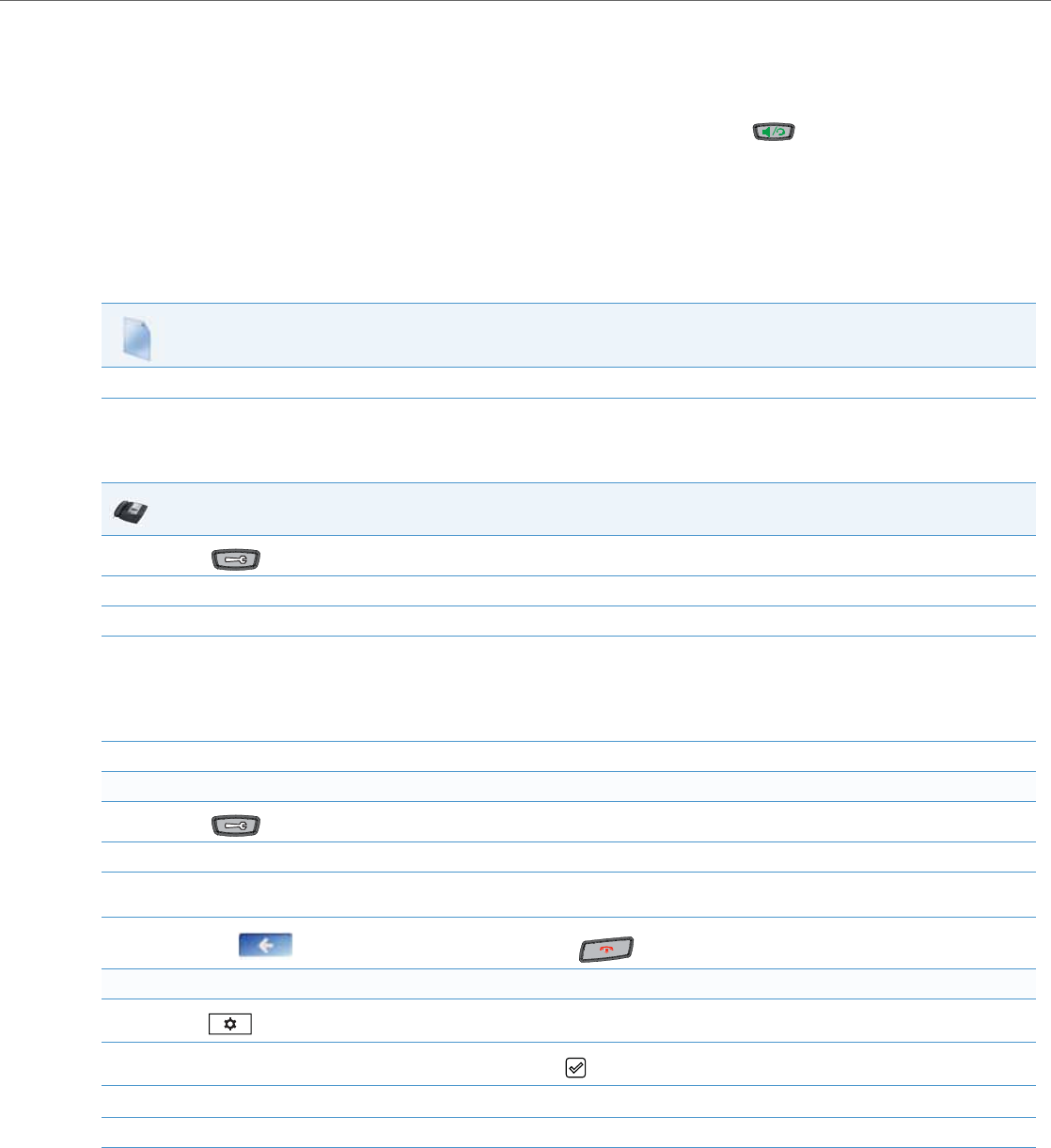
Operational Features
41-001343-02 REV04 – 05.2014 5-37
Live Dialpad
The "Live Dialpad" option on the IP phone turns the Live Dial Pad mode ON or OFF. With live dial pad ON, the IP phone
automatically dials out and turns ON Handsfree mode as soon as a dial pad key or softkey is pressed. With live dial pad OFF,
if you dial a number while the phone is on-hook, lifting the receiver or pressing the initiates a call to that number.
*Availability of feature dependant on your phone system or service provider.
A User can turn the “Live Dialpad” ON and OFF using the IP Phone UI only. A System Administrator can turn it ON and OFF
using the IP Phone UI or the configuration files.
Enabling/Disabling Live Dialpad Using the Configuration Files
Use the following procedure to enable/disable Live Dialpad on the IP Phones.
Enabling/Disabling Live Dialpad Using the IP Phone UI
Use the following procedure to enable/disable Live Dialpad on the IP Phones.
Configuration Files
For specific parameters you can set in the configuration files, see Appendix A, the section, “Live Dialpad Settings” on pageA-58.
IP Phone UI
1. Press on the phone to enter the Options List.
2. Select Preferences.
3. Select Live Dialpad.
4. On 3-Line LCD phones:
Press the UP and DOWN arrow keys to toggle the live dialpad setting ON or OFF.
On 8 and 11-Line LCD phones:
Press Change to toggle the live dialpad setting ON or OFF.
5. Press Done to save the setting.
For the 6739i:
1. Press on the phone to enter the Options List.
2. Select Live Dial.
3. Select the Off/On button next to Live Dialpad and touch the applicable button to enable or
disable the feature.
4. Press the to return to the previous menu or press the to return to the idle screen.
For the 6867i:
1. Press to enter the Options List.
2. Navigate to the Dialpad -> Live Dialpad option and press the button or Select softkey.
3. Use the 5 and 2 keys to scroll through and enable (On) or disable (Off) the live dialpad feature.
4. Press the Save softkey to save your changes.

Operational Features
5-38 41-001343-02 REV04 – 05.2014
Language
The IP phones support several different languages. You can have the IP phone UI and the Aastra Web UI display in a spe-
cific language as required. When you set the language to use, all of the display screens (menus, services, options, config-
uration parameters, etc.) display in that language. The IP phones support the following languages:
Loading Language Packs
You make languages available to use on the phone by loading language packs from the configuration server to the local
<MAC>.cfg configuration file. You can use the configuration files or the Aastra Web UI to perform the download. Each
language pack consists of the IP Phone UI and Aastra Web UI translated in a specific language.
Available Language Associated Language File
(included in the firmware file when downloaded from configuration server)
English Default (resides on the phone)
Czech (UTF-8)* lang_cs.txt
Czech (ASCII)* lang_cs_op.txt
Catalan* lang_ct.txt
Valencian* lang_ct_va.txt
Welsh* lang_cy.txt
German* lang_de.txt
Danish* lang_da.txt
Spanish lang_es.txt
Mexican Spanish lang_es_mx.txt
Finnish* lang_fi.txt
French lang_fr.txt
Canadian French lang_fr_ca.txt
Italian* lang_it.txt
Dutch* lang_nl.txt
Dutch (Netherlands)* lang_nl_nl.txt
Norwegian* lang_no.txt
Polish (ASCII)* lang_pl.txt
Polish (UTF-8)* lang_pl_pl.txt
Portuguese* lang_pt.txt
Portuguese Brazilian* lang_pt_br.txt
Romanian* lang_ro.txt
Russian* lang_ru.txt
Slovak (UTF-8)* lang_sk.txt
Slovak (ASCII)* lang_sk_op.txt
Swedish* lang_sv.txt
Turkish* lang_tr.txt
Notes:
•The above languages denoted with asterisks (i.e. *) are not applicable to the 6757i CT cordless handset.
•The 6753i does not support UTF-8 encoded language files.
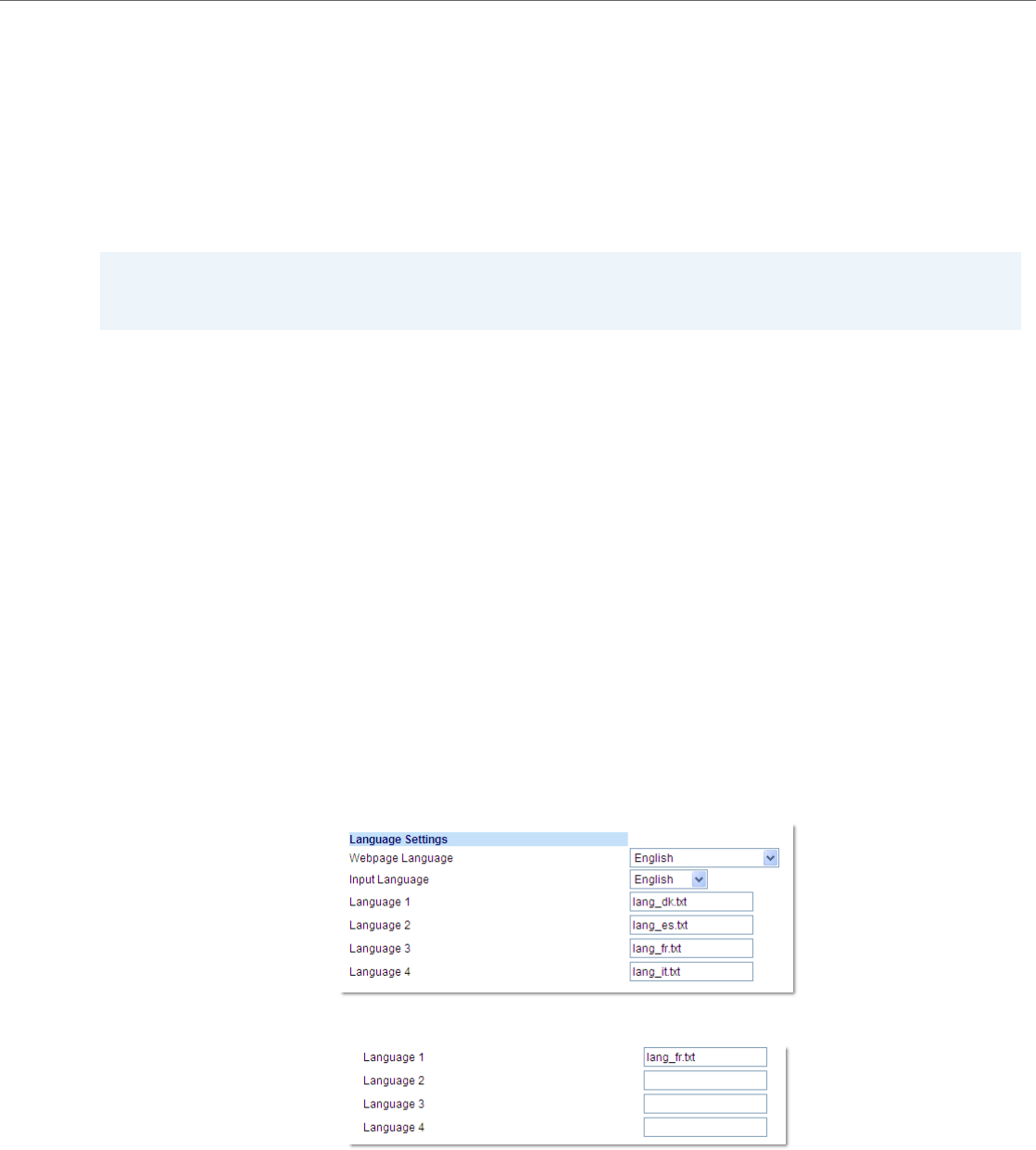
Operational Features
41-001343-02 REV04 – 05.2014 5-39
Loading Language Packs via the Configuration File (<mac>.cfg)
Using the configuration files, you specify a language pack to load in the following format:
lang_<ISO 639>_<ISO 3166>.txt
or
lang_<ISO 639>.txt
where <ISO 639> is the language code specified in Standard ISO 639
(see Appendix A, the section, Language Codes (from Standard ISO 639) on page A-137) and <ISO 3166> is the country
code specified in Standard ISO 3166 (see Country Codes (from Standard ISO 3166) on page A-138). The <ISO 3166>
attribute is optional.
Example
The following is an example of the parameters you would enter in the <MAC>.cfg file to load a French, Italian, German, and
Spanish language pack to the IP phone.
language 1: lang_fr_ca.txt
language 2: lang_it.txt
language 3: lang_de.txt
language 4: lang_es.txt
The above entries in the <MAC>.cfg file tells the phone which language packs to load. When the language pack(s) have
loaded, you must then use the configuration files IP Phone UI to specify which language to display on the IP phone. You
must use the Aastra Web UI to specify the language to use in the Web UI.
References
For more information about specifying the language to use, see the section, “Specifying the Screen Language to Use” on
page5-40.
For more information about language codes and country codes, see Appendix A, the section, “Language Pack Settings” on
page A-136.
Loading Language Packs via the Aastra Web UI
Using the Aastra Web UI, you can specify a language pack to load using the parameters at Basic Settings->Preferences-
>Language Settings.
You use the following fields in the Aastra Web UI to specify which language packs to load:
Once the language pack is loaded to the phone, it is available for selection from either the configuration files, the IP Phone
UI or the Aastra Web UI.
Note:
Adding/changing language packs can only be done at bootup of the IP phone. The default language (English) cannot
be changed or removed.
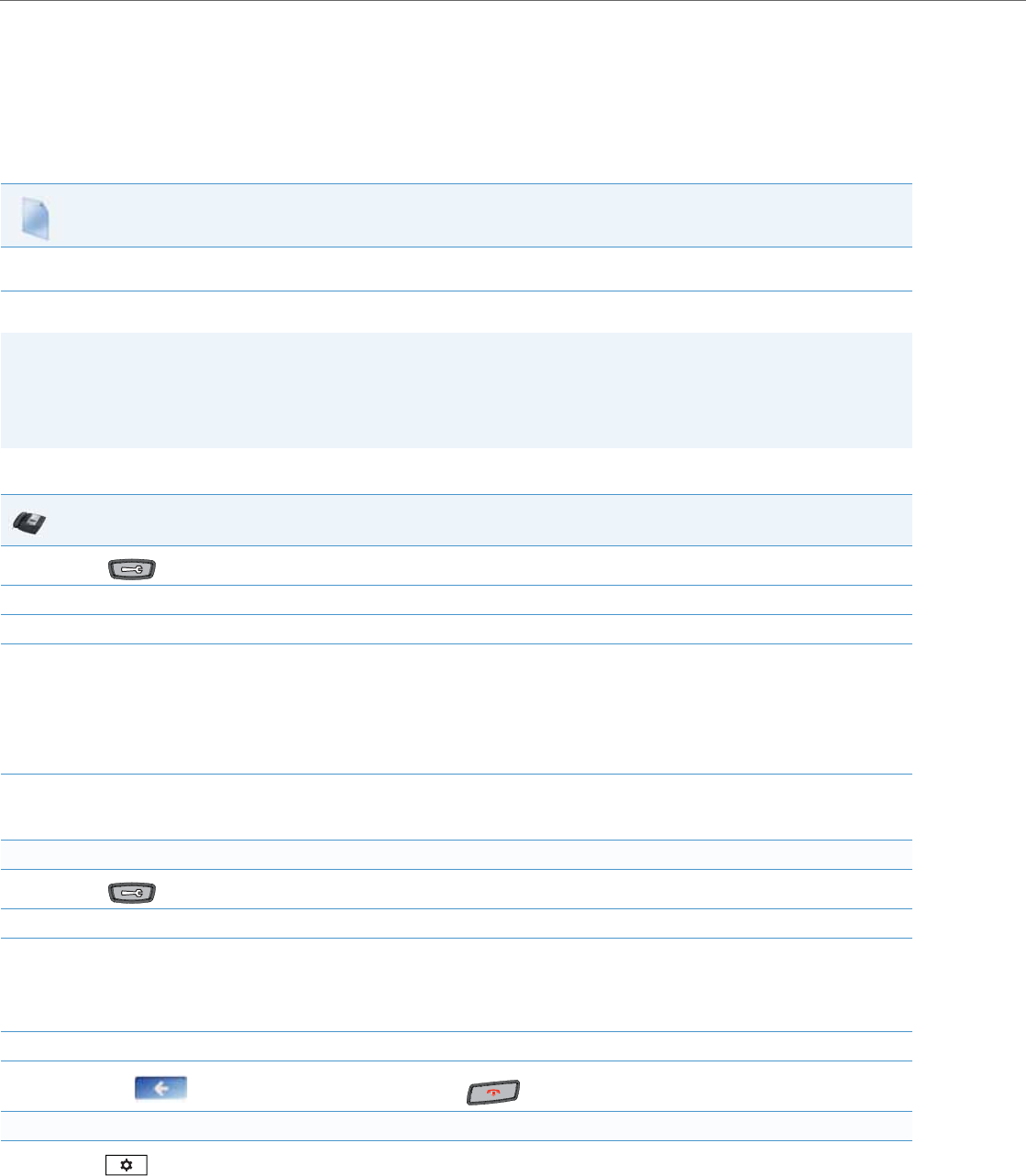
Operational Features
5-40 41-001343-02 REV04 – 05.2014
Specifying the Screen Language to Use
Once the language pack(s) have loaded, you must then specify which language to use on the phone. After the phone has
booted up, you can specify which language(s) to use. You can use the configuration files (via the “language” parameter)
and the IP Phone UI to specify the language for the IP Phone UI. You can use the configuration files (via the “web lan-
guage” parameter) and Aastra Web UI to specify the files for the Aastra Web UI.
Use the following procedures to specify the language to use on the IP phone.
Configuration Files
For specific parameters you can set in the configuration files, see Appendix A, the section, “Language Settings” on pageA-134 and “Language Pack Set-
tings” on pageA-136.
Notes:
•If you specify the language to use on the phone via the configuration files, you must reboot the phone for the
changes to take affect.
•All languages may not be available for selection. The available languages are dependant on the language packs cur-
rently loaded to the IP phone.
IP Phone UI
1. Press on the phone to enter the Options List.
2. Select Language.
3. Select Screen Language.
4. Select the applicable language.
Notes:
•Valid values for the 6757i CT cordless handset are English, French, and Spanish only.
•All languages may not be available for selection. The available languages are dependant on the language packs currently loaded to the IP
phone. English is the default language and cannot be changed or removed. For more information about loading language packs, see
“Loading Language Packs” on page5-38.
5. Press Done to save the changes.
The change is dynamic. The IP phone UI displays all menu items in the language you chose.
For the 6739i:
1. Press on the phone to enter the Options List.
2. Press the <Language> button.
3. Press the <Screen Language> button. The screen displays a list of available languages.
Note:
All languages may not be available for selection. The available languages are dependant on the language packs currently loaded to the IP
phone. English is the default language and cannot be changed or removed. For more information about loading language packs, see “Load-
ing Language Packs” on page5-38.
4. Press the screen language you want to set on the phone. The change takes place immediately.
5. Press the to return to the previous menu or press the to return to the idle screen.
For the 6867i:
1. Press to enter the Options List.
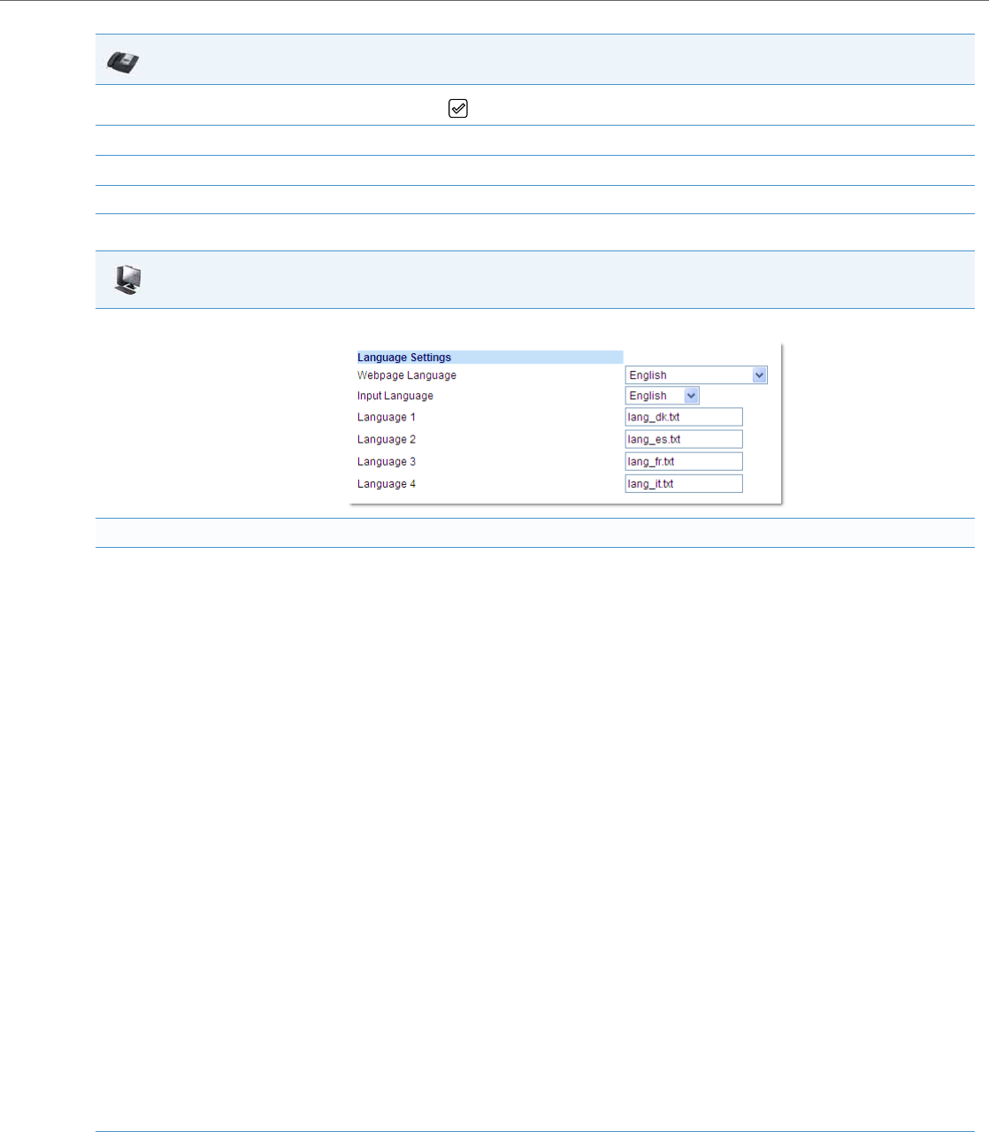
Operational Features
41-001343-02 REV04 – 05.2014 5-41
2. Navigate to the Language option and press the button or Select softkey.
3. With Screen Language highlighted press the 4 key to move to selection column.
4. Use the 5 and 2 keys to scroll through and choose the desired screen language.
5. Press the Save softkey to save your changes.
Aastra Web UI
1. Click on Basic Settings->Preferences->Language Settings.
Loading the Language Pack
2. In the “Language N” fields, enter the file name of the language pack you want to use to display a specific language in the Aastra Web UI. For
example, you could enter any of the following in the “Language 1”, “Language 2”, “Language 3”, and “Language 4” fields to display the Aastra
Web UI in the respective language:
•lang_cs.txt (Czech - UTF-8)
•lang_cs_op.txt (Czech - ASCII)
•lang_ct.txt (Catalan)
•lang_ct_va.txt (Valencian)
•lang_cy.txt (Welsh)
•lang_de.txt (German)
•lang_da.txt (Danish)
•lang_es.txt (Spanish)
•lang_es_mx.txt (Mexican Spanish)
•lang_fi.txt (Finnish)
•lang_fr.txt (French)
•lang_fr_ca.txt (Canadian French)
•lang_it.txt (Italian)
•lang_nl.txt (Dutch)
•lang_nl_nl.txt (Dutch - Netherlands)
•lang_no.txt (Norwegian)
•lang_pl.txt (Polish - ASCII)
•lang_pl_pl.txt (Polish - UTF-8)
•lang_pt.txt (Portuguese)
•lang_pt_br.txt (Brazilian Portuguese)
•lang_ro.txt (Romanian)
•lang_ru.txt (Russian)
•lang_sk.txt (Slovak - UTF-8)
•lang_sk_op.txt (Slovak - ASCII)
•lang_sv.txt (Swedish)
•lang_tr.txt (Turkish)
You must have the language pack(s) already loaded to your phone in order to use them. For more information about loading language
packs, see “Loading Language Packs” on page5-38.
For more information about language codes and country codes, see Appendix A, the section, “Language Pack Settings” on pageA-136.
3. Click Save Settings to save your changes.
IP Phone UI

Operational Features
5-42 41-001343-02 REV04 – 05.2014
Specifying the Input Language to Use
The phones support text and character inputs in various languages (English, German, French, Spanish, Italian, Portu-
guese, Russian, and Nordic).
Inputting textual or character information into the IP Phone UI, Aastra Web UI, and XML scripts can now be done in vari-
ous languages using the keypad on the phone. The System Administrator and User can enable this feature using the Aas-
tra Web UI or the IP Phone UI. An Administrator can also use the configuration files to enable this feature. Users can then
use text and characters in a specific language when performing inputs on the phone.
The following tables identify the language characters that a User can enter on the 5i Series phones that support the
Input Language feature.
Keypad Text/Character Input Tables
English (default)
Specifying the Language to Use in the Aastra Web UI
4. After restarting your phone, log back in using the Aastra Web UI.
5. Click on Basic Settings->Preferences->Language Settings.
6. In the “Webpage Language” field, select a language to apply to the Aastra Web UI.
Notes:
•Valid values for the 6757i CT cordless handset are English, French, and Spanish only.
•All languages may not be available for selection. The available languages are dependant on the language packs currently loaded to the IP
phone. English is the default language and cannot be changed or removed. For more information about loading language packs, see
“Loading Language Packs” on page5-38.
7. Click Save Settings to save your changes.
The Aastra Web UI displays all screens in the language you chose.
Key Uppercase Characters Lowercase Characters
0 0 0
1 1;=_,-'&() 1.:;=_,-'&()
2 ABC2 abc2
3 DEF3 def3
4 GHI4 ghi4
5 JKL5 jkl5
6 MNO6 mno6
7 PQRS7 pqrs7
8 TUV8 tuv8
9 WXYZ9 wxyz9
* * <SPACE> * <SPACE>
# #/\@ #/\@
Aastra Web UI

Operational Features
41-001343-02 REV04 – 05.2014 5-43
French
Spanish
Key Uppercase Characters Lowercase Characters
0 0 0
1 1.:;=_,-'&() 1.:;=_,-'&()
2 ABC2ÀÂÇÁÅÆ abc2àâçáåæ
3 DEF3ÉÈÊË def3éèêë
4 GHI4ÎÏ ghi4îï
5 JKL5 jkl5
6 MNO6ÑÓÒÔÖ mno6ñóòôö
7 PQRS7 pqrs7
8 TUV8ÚÙÛÜ tuv8úùûü
9 WXYZ9 wxyz9
* * <SPACE> * <SPACE>
# #/\@ #/\@
Key Uppercase Characters Lowercase Characters
0 0 0
1 1.:;=_,-'&() 1.:;=_,-'&()
2 ABC2ÁÀÇ abc2áàç
3 DEF3ÉÈ def3éè
4 GHI4ÏÍ ghi4ïí
5 JKL5 jkl5
6 MNO6ÑÓÒ mno6ñóò
7 PQRS7 pqrs7
8 TUV8ÚÜ tuv8úü
9 WXYZ9 wxyz9
* * <SPACE> * <SPACE>
# #/\@ #/\@

Operational Features
5-44 41-001343-02 REV04 – 05.2014
German
Italian
Key Uppercase Characters Lowercase Characters
0 0 0
1 1.:;=_,-'&() 1.:;=_,-'&()
2 ABC2ÄÀ abc2äà
3 DEF3É def3é
4 GHI4 ghi4
5 JKL5 jkl5
6 MNO6Ö mno6ö
7 PQRS7ß pqrs7ß
8 TUV8Ü tuv8ü
9 WXYZ9 wxyz9
* * <SPACE> * <SPACE>
# #/\@ #/\@
Key Uppercase Characters Lowercase Characters
0 0 0
1 1.:;=_,-'&() 1.:;=_,-'&()
2 ABC2ÀCÇ abc2àcç
3 DEF3ÉÈË def3éèë
4 GHI4 ghi4
5 JKL5 jkl5
6 MNO6ÓÒ mno6óò
7 PQRS7 pqrs7
8 TUV8Ù tuv8ù
9 WXYZ9 wxyz9
* * <SPACE> * <SPACE>
# #/\@ #/\@

Operational Features
41-001343-02 REV04 – 05.2014 5-45
Portuguese
Russian
Key Uppercase Characters Lowercase Characters
0 0 0
1 1.:;=_,-'&() 1.:;=_,-'&()
2 ABC2ÁÀÂÃÇ abc2áàâãç
3 DEF3ÉÊ def3éê
4 GHI4Í ghi4í
5 JKL5 jkl5
6 MNO6ÓÔÕ mno6óôõ
7 PQRS7 pqrs7
8 TUV8ÚÜ tuv8úü
9 WXYZ9 wxyz9
* * <SPACE> * <SPACE>
# # / \ @ # / \ @
Key Uppercase Characters Lowercase Characters
0 0 0
1 1.:;=_,-'&() 1.:;=_,-'&()
2 АБВГ2ABC aбвг2abc
3 ДЕЁЖЭ3DEF Дeëжз3def
4 ИЙКЛ4GHI ийкл4ghi
5 МНОП5JKL мноп5jkl
6 РСТУ6MNO рсту6mno
7 ФХЦЧ7PQRS фхЧч7pqrs
8 ШЩЪЫ8TUV шщъы8tuv
9 ЬЗЮЯ9WXYZ ьзюя9wxyz
* * <SPACE> * <SPACE>
# #/\@ #/ \@

Operational Features
5-46 41-001343-02 REV04 – 05.2014
Nordic
Configuring Language Input Using the Configuration Files
An Administrator can specify the input language to use by entering a specific parameter in the configuration files. An
Administrator must enter the following parameter to enable this feature:
•input language
Use the following procedures to specify the input language to use on the IP phone.
Key Uppercase Characters Lowercase Characters
00 0
1 1.:;=_,-'&() 1.:;=_,-'&()
2ABC2ÅÄÆÀ abc2åäæà
3DEF3É def3é
4GHI4 ghi4
5JKL5 jkl5
6MNO6ÖØ mno6öø
7PQRS7ß pqrs7ß
8TUV8Ü tuv8ü
9WXYZ9 wxyz9
* * <SPACE> * <SPACE>
##/\@ #/\@
Configuration Files
For specific parameters you can set in the configuration files, see Appendix A, the section, “Language Settings” on pageA-134.
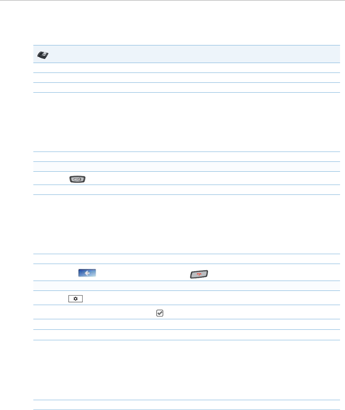
Operational Features
41-001343-02 REV04 – 05.2014 5-47
Configuring Language Input Using the IP Phone UI
Once “Language Input” is enabled, an Administrator or User can change the input language on the phone using the IP
Phone UI. The “Input Language” option appears under the Language option in the IP Phone UI.
Use the following procedure to change the input language using the IP Phone UI.
IP Phone UI
1. Press the Options key.
2. Select Language from the Options List.
3. Select Input Language from the Language List.
4. Select the language you want to use on the IP phone for inputting text and characters. Valid values are:
•English (default)
•Français (French)
•Español (Spanish)
•Deutsch (German) (not applicable to 6757i CT cordless handset)
•Italiano (Italian) (not applicable to 6757i CT cordless handset)
•Português (Portuguese) (not applicable to 6757i CT cordless handset)
•Русский (Russian) (not applicable to 6757i CT cordless handset)
•Nordic
5. Press Done when you have selected a language.
For the 6739i:
1. Press on the phone to enter the Options List.
2. Press the <Language> button.
3. Press the <Input Language> button. The following options display:
•English (default)
•Français (French)
•Español (Spanish)
•Deutsch (German)
•Italiano (Italian)
•Português (Portuguese)
•Русский (Russian)
•Nordic
4. Press the input language you want to set on the phone. The change takes place immediately.
5. Press the to return to the previous menu or press the to return to the idle screen.
For the 6867i:
1. Press to enter the Options List.
2. Navigate to the Language option and press the button or Select softkey.
3. Press the 2 key to highlight the Input Language option.
4. With Input Language highlighted press the 4 key to move to selection column.
5. Use the 5 and 2 keys to scroll through and choose the desired input language. Valid values are:
•English (default)
•Français (French)
•Español (Spanish)
•Deutsch (German)
•Italiano (Italian)
•Português (Portuguese)
•Русский (Russian)
•Nordic
6. Press the Save softkey to save your changes.
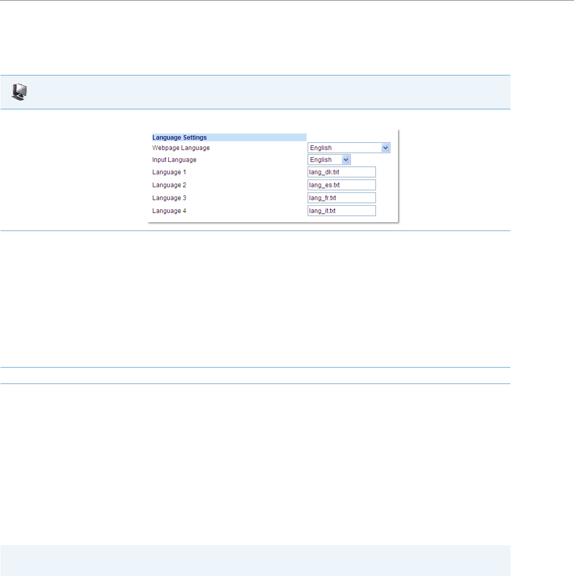
Operational Features
5-48 41-001343-02 REV04 – 05.2014
Configuring Language Input Using the Aastra Web UI
Once “Language Input” is enabled, an Administrator or User can also change the input language on the phone using the
Aastra Web UI. The “Input Language” option appears at the path Basic Settings->Preferences->Language Settings.
Use the following procedure to set the input language using the Aastra Web UI.
Configuring Language Input for an XML Application
A System Administrator can enable input languages in XML applications using the <AastraIPPhoneInputScreen>
object and the “inputLanguage” attribute.
Reference
For more information about using XML objects for defining input language, contact Aastra Customer Support regarding
the Aastra XML Development Guide.
UTF- 8 Codec for Multi-National Language Support
The IP Phones and expansion modules include support for ISO 8859-2 (Latin2) of multi-national languages when display-
ing and inputting in the IP Phone UI and the Aastra Web UI.
UTF-8 is also compatible with XML encoding on the IP Phones.
Aastra Web UI
1. Click on Basic Settings-> Preferences->Language Settings.
2. Select a language from the "Input Language" field. Setting this field allows you to specify the language to use when entering text in the Aas-
tra Web UI, IP Phone UI, or in XML applications on the phone. Valid values are:
•English (default)
•Français (French)
•Español (Spanish)
•Deutsch (German) (not applicable to 6757i CT cordless handset)
•Italiano (Italian) (not applicable to 6757i CT cordless handset)
•Português (Portuguese) (not applicable to 6757i CT cordless handset)
•Русский (Russian) (not applicable to 6757i CT cordless handset)
•Nordic
Note:
Available input languages are dependent on the configuration enabled by your System Administrator.
3. Click Save Settings to save your changes.
Note:
This feature is not applicable to the handsets on the 6757i CT and the 9480i CT.
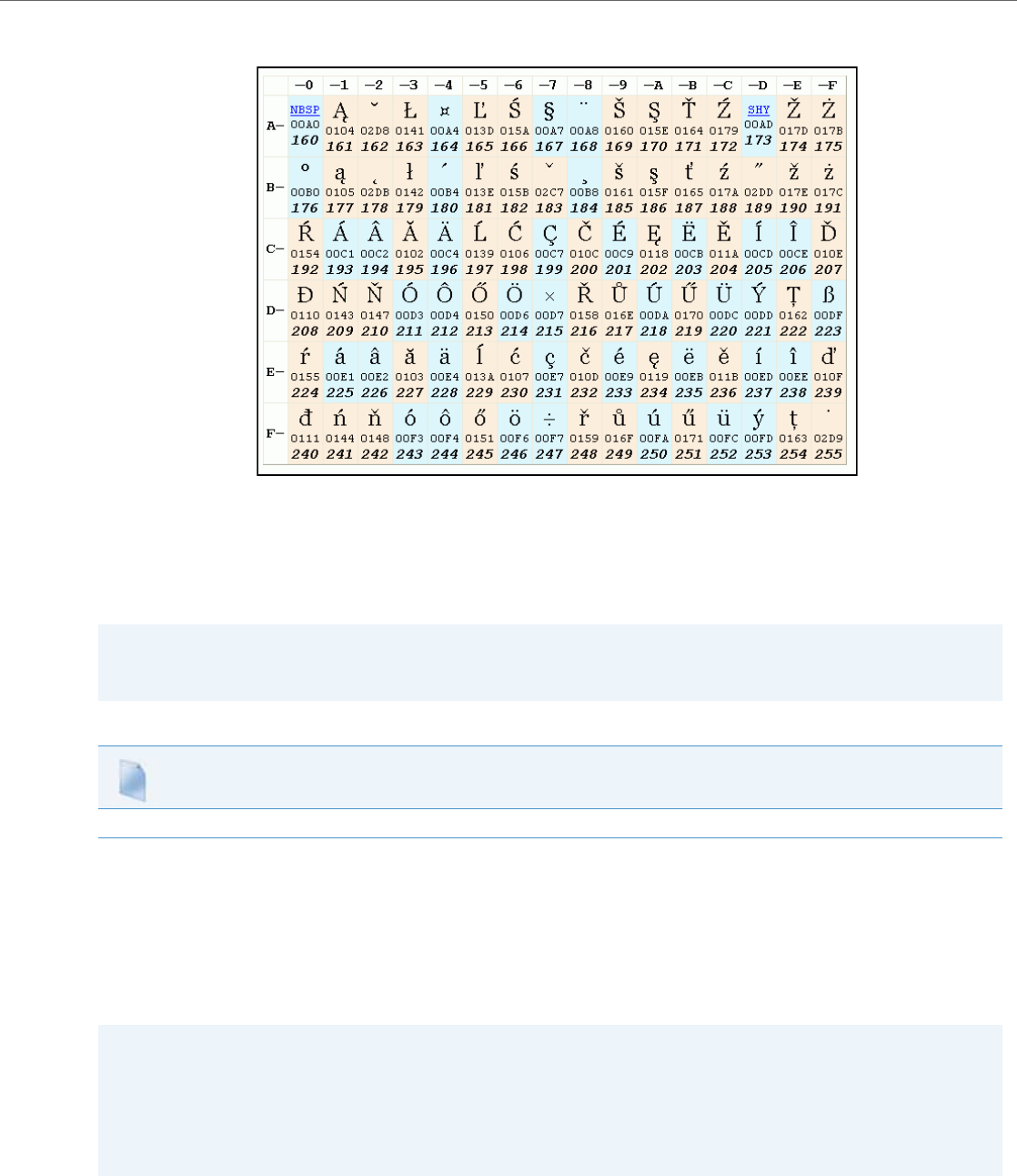
Operational Features
41-001343-02 REV04 – 05.2014 5-49
The following table illustrates the Latin 2 character set now used on the IP Phones.
Minimum Ringer Volume
To prevent the user from turning off the ringer, an Administrator can configure a parameter called “ringer volume mini-
mum” to set the minimum ringer volume level. When the minimum ringer level is reached while the user keeps pressing
the button, the level of sound does not change.
Locking IP Phone Keys
The IP phones allow you to lock or unlock programmable keys, softkeys, keypad keys, hard keys, cordless handset keys,
and expansion keys (for expansion modules). When key locking is enabled, the phone locks the key with the provisioned
local settings and prevents users from changing or configuring the key. In this case, the local settings (i.e. those configured
through the Web UI or [for the 6739i] the phone UI) take precedence over any key parameters defined in the configuration
files.
Note:
This minimum ringer volume does not affect the “silent” ring tone. When the silent ring tone is selected, no ringing will
be played by the phone
Configuration Files
For the specific parameter you can set in the configuration files, see Appendix A, the section, “Minimum Ringer Volume” on pageA-150.
Notes:
•If no settings are configured locally but the key type is defined in a configuration file, the phone will lock the respec-
tive key with the type defined in the configuration file along with any values associated with the additional key
parameters (e.g. for softkeys, “softkeyN label”, “softkeyN value”, “softkeyN line”, “softkeyN states”).
•Administrators also have the option of simply adding an exclamation mark (i.e. “!”) in front of the respective key
parameters to lock the keys to the values defined in the configuration files, overriding any locally configured settings
(see Locking Parameters in the Configuration File on page 2-15 for further details).

Operational Features
5-50 41-001343-02 REV04 – 05.2014
You can lock and unlock keys using the configuration files only. When viewing the locked key via the Aastra Web UI, the
key is grayed out (disabled) and cannot be changed. Locking is dynamic for XML pushes.
You use the following “locking” parameters in the configuration files to lock the softkeys and/or programmable keys on
all the phones. If no key settings are configured locally, the locking parameters impact existing softkey and programma-
ble key parameters defined in the configuration files as detailed in the table below.
Locking the IP Phone Keys using the Configuration Files
Use the following procedures to lock the softkeys and programmable keys on the IP phone.
Locking Parameter Impacted Parameters Applicable Phone Models
softkeyN locked softkeyN type
softkeyN label
softkeyN value
softkeyN line
softkeyN states
9480i
9480i CT
6735i
6737i
6739i
6755i
6757i
6757i CT
6867i
topsoftkeyN locked topsoftkeyN type
topsoftkeyN label
topsoftkeyN value
topsoftkeyN line
6737i
6757i
6757i CT
6867i
prgkeyN locked prgkeyN type
prgkeyN value
prgkeyN line
9143i
6730i
6731i
6735i
6753i
6755i
6863i
6865i
pnhkeypadN locked pnhkeypadN value
pnhkeypadN line
All IP phone models
featurekeyN locked featurekeyN type
featurekeyN label
9480i CT
6757i CT
expmodX keyN locked expmodX keyN type
expmodX keyN label (M675i only)
expmodX keyN value
expmodX keyN line
6700i and 6800i-series phones only
(not applicable to the 6730i, and 6731i)
hardkeyN locked hardkeyN type
hardkeyN value
hardkeyN line
6867i
Note:
The 3-line LCD phones prevent users from setting a Speeddial key via the Phone UI on a key that has been locked.
Configuration Files
For specific parameters you can set in the configuration files, see Appendix A, the section,“Locking Keys” on pageA-187.

Operational Features
41-001343-02 REV04 – 05.2014 5-51
Locking/Unlocking the SAVE and DELETE keys
By default, the 6730i, 6731i, 6753i, and 6865i have two keys dedicated to the Save and Delete functions. These two keys
can be made programmable by the Administrator, freeing up the total number of programmable keys if required.
If a System Administrator unlocks the Save and Delete keys, these keys can be configured with the same functions that
are available for the other programmable keys. Only the System Administrator can unlock these keys.
The Save key allows you to save entries to the Directory and perform a Save-To from the Callers List. It also allows you to
save speeddial information to a programmable key. You can also use the Save key while using specific XML applications.
The Delete key allows you to remove entries from the Directory List and Callers List. (Must enter the Directory or Callers list
and select an entry, then press twice to delete entry).
By default, the Save and Delete keys are locked so that a user can use them for saving and deleting only. An Administrator
can unlock these keys using the configuration files, allowing the keys to be programmed with other functions if required.
An Administrator can use the following parameters in the configuration file to lock and unlock the Save and Delete keys:
For the 6730i, 6731i, and 6865i:
•prgkey5 locked
•prgkey6 locked
For the 6753i:
•prgkey1 locked
•prgkey2 locked
The value of "0" unlocks the keys, and the value of "1" locks the keys. The default is "1" (lock).
The following is an example of unlocking the Save and Delete keys on the 6753i using the configuration files:
Example:
prgkey1 locked: 0
prgkey2 locked: 0
Once the Save and Delete keys are unlocked, a User can change the function of the keys using the Aastra Web UI. An
Administrator can change the function of the keys using the Aastra Web UI or the configuration files.
Locking and Unlocking the Save and Delete Keys Using the Configuration Files
Note:
Applicable to the 6730i, 6731i, 6753i, and 6865i IP Phones only.
Notes:
•If you change the functions of the Save and Delete keys, and then an Administrator locks the respective keys, the
functions are automatically set back to the default settings of "Save" and "Delete"
•The Save and Delete functions are limited to Key 1 and Key 2 on the 6753i and Keys 5 and 6 on the 6730i, 6731i, and
6865i IP phones only.
Configuration Files
For the specific parameter you can set in the configuration files, see Appendix A, the section,
“Locking the SAVE and DELETE Keys”
on
pageA-190
.

Operational Features
5-52 41-001343-02 REV04 – 05.2014
Local Dial Plan
A dial plan describes the number and pattern of digits that a user dials to reach a particular telephone number. Access
codes, area codes, specialized codes, and combinations of the number of digits dialed are all part of a dial plan. For
instance, the North American Public Switched Telephone Network (PSTN) uses a 10-digit dial plan that includes a 3-digit
area code and a 7-digit telephone number. Most PBXs support variable length dial plans that use 3 to 11 digits. Dial plans
must comply with the telephone networks to which they connect. Only totally private voice networks that are not linked
to the PSTN or to other PBXs can use any dial plan.
The Dial Plan field accepts up to 512 characters. If a User enters a dial plan longer than 512 characters, or a parsing error
occurs, the phone uses the default dial plan of “x+#|xx+*”. You configure the SIP Local Dial Plan using the Aastra Web UI
or the configuration files.
The IP phone SIP local dial plan available symbols are as follows:
Dial Plan Example
An example of a SIP Local Dial Plan is:
[01]XXX|[2-8]XXXX|91XXXXXX
XXXX|X+.|*XX
The dial plan in the above example can accept any 4-digit dial strings that begin with a '0' or '1', any 5-digit dial strings
that begin with a '2' up to '8', any 12-digit dial strings that begin with '91', any non-empty digit string that ends with a '.' or
any 2-digit code that begins with a '*'.
Prefix Dialing
The IP phones support a prefix dialing feature for outgoing calls.
You can manually dial a number or dial a number from a list. The phone automatically maps the pre-configured pre-
pended digit in the configuration, to the outgoing number. When a match is found, the prepended digits are added to
the beginning of the dial string and the call is dialed.
You can enable this feature by adding a prepend digit(s) to the end of the Local Dial Plan parameter string in the config-
uration files or the Aastra Web UI at
Basic Settings->Preferences->General.
Symbol Description
0, 1, 2, 3, 4, 5, 6, 7, 8, 9 Digit symbol
; Allows a secondary dial tone to be audible before dialing a number.
X Match any digit symbol (wildcard)
*, #, . Other keypad symbol
| Expression inclusive OR
+ 0 or more of the preceding digit symbol or [] expression
[] Symbol inclusive OR
- Used only with [], represent a range of acceptable symbols; For example, [2-8]
; Used when a secondary dial tone is required on the phone. (For example, “9;xxxxxx”, when a user has to
dial “9” to get and outside line and needs a secondary dial one presented
Note:
The prepend digits are also added if the dialing times-out on a partial match.

Operational Features
41-001343-02 REV04 – 05.2014 5-53
For example, if you add a prepend map of “[2-9]XXXXXXXXX,91”, the IP phone adds the digits “91” to any 10-digit number
beginning with any digit from 2 to 9 that is dialed out. Other examples of prepend mappings are:
•1X+#,9 (Prepends 9 to any digit string beginning with “1” and terminated with “#”.)
•6XXX,579 (Prepends “579” to any 4-digit string starting with “6”.)
•
[4-6]XXXXXX,78
(Prepends “78” to any 7-digit string starting with “4”, “5”, or “6”.)
Example:
If you enter the following dial string for a local dial plan:
sip dial plan: 1+#,9
where “9” is the prepended digit, and you dial the following number:
15551212
the IP phone automatically adds the “9” digit to the beginning of the dialed number before the number is forwarded as
915551212.
SIP Dial Plan Terminator
The IP phone provides a feature that allows an administrator to configure whether or not pressing the hash/pound (i.e. “#”)
key, while performing an outgoing call on an open line, should be sent as %23 to the proxy in the dial string or if the key
should be used as a dial plan terminator (i.e. dials out the call immediately). By default, the hash/pound key is configured
as a dial plan terminator; however, an administrator can change the behavior using the Aastra Web UI or the configuration
files.
Digit Timeout
The IP phone allows you to configure a “Digit Timeout” feature on the IP phone. The Digit Timeout is the time, in seconds,
between consecutive key presses on the IP phone’s keypad. The default for this parameter is 4 seconds. If you press a key
on the phone and wait 4 seconds before pressing the next key, the key times out and cancels the digit selection. You must
press consecutive keys before the timeout occurs.
Secondary Dial Tone
The IP phones now support a feature that allows the user to dial a predefined dial string, obtain a dial tone, and continue
dialing. A User or Administrator can configure this using the existing Dial Plan feature on the phone.
You can enter a new character string in the dial plan that allows you to configure the secondary dial tone. The character
string is of the form ".;." , where the period indicates an arbitrary number of digits and the semicolon indicates that the
phone is to present a dial tone after the previous dialed digit. For example, in the string:
"9;xxxxx"
the user dials “9” to get the outside line, listens for the dial tone, and continues to dial the applicable number. The “;” tells
the phone to present a second dial tone after the previously dialed digit. “The “xxxxx” in the example tells the phone that
a phone number is dialed after the secondary dial tone is audible.
You can enter the Secondary Dial Tone string in the Dial Plan using the configuration files or the Aastra Web UI.
You use the following parameter in the configuration files to configure a secondary dial tone:
•sip dial plan
Example:
sip dial plan: “9;5551313”
Note:
You can configure a local dial plan via the configuration files or the Aastra Web UI.
Note:
You can configure a local dial plan via the configuration files or the Aastra Web UI.
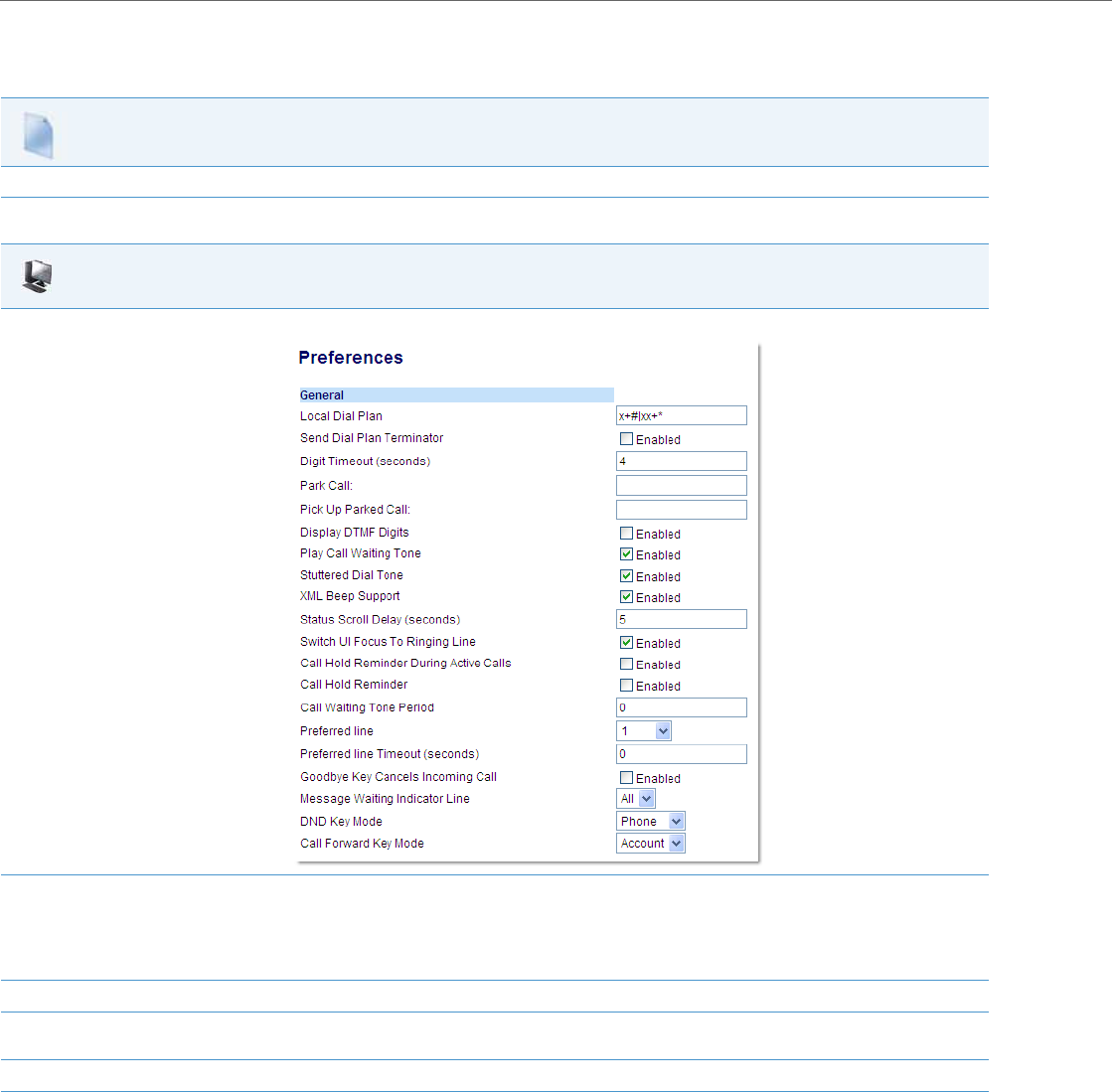
Operational Features
5-54 41-001343-02 REV04 – 05.2014
Configuring the SIP Local Dial Plan, Dial Plan Terminator, and Digit Timeout
Use the following procedures to configure the SIP Local Dial Plan using the configuration files or the Aastra Web UI.
Configuration Files
For specific parameters you can set in the configuration files, see Appendix A, the section, “SIP Local Dial Plan Settings” on pageA-58.
Aastra Web UI
1. Click on Basic Settings-> Preferences->General.
2. In the "Local Dial Plan" field, enter a valid local dial plan (up to 512 alphanumeric characters) for the IP phone. Default is X+#|XX+*. Enter pre-
pended digits or a “;”to present a secondary dial tone if required.
Note:
If a User enters a dial plan longer than 512 characters, or a parsing error occurs, the phone uses the default dial plan of “x+#|xx+*”.
3. Enable the "Send Dial Plan Terminator" field by checking the check box. (Disable this field by unchecking the box). Default is disabled.
4. In the "Digit Timeout (in seconds)" field, enter a timeout value. This is the length of time, in seconds, he phone waits before dialing. Default
is 4 seconds.
5. Click Save Settings to save your changes.

Operational Features
41-001343-02 REV04 – 05.2014 5-55
Suppressing DTMF Playback
A feature on the IP phones allows administrators to enable or disable the suppression of DTMF playback when a number is
dialed from the softkeys and programmable keys.
When suppression of DTMF playback is disabled, and you press a softkey or programmable key, the IP phone dials the
stored number and displays each digit as dialed in the LCD window.
When the suppression of DTMF playback is enabled, the IP phone dials the stored number and displays the entire number
immediately in the LCD window, allowing the call to be dialed much faster.
DTMF playback suppression is enabled by default. The “suppress dtmf playback” parameter can be configured using the
configuration files.
Configuring Suppression of DTMF Playback
Use the following procedures to configure the suppression of DTMF playback on the IP phone.
Display DTMF Digits
A feature on the IP phones allows administrators to enable or disable DTMF (dual-tone multi-frequency) digits to display
to the IP phone when using the keypad to dial, or when dialing from a softkey or programmable key.
DTMF is the signal sent from the phone to the network that you generate when you press the phone’s touch keys. This is
also known as “touchtone” dialing. Each key you press on your phone generates two tones of specific frequencies. One
tone is generated from a high-frequency group of tones and the other from a low frequency group.
If you enable the Display DTMF Digits parameter, the digits you are dialing from the keypad or from a softkey or program-
mable key display to the IP phone’s LCD display. This parameter is disabled by default (no digits display when dialing).
You can enable the “display dtmf digits” parameter using the configuration files or the Aastra Web UI.
Configuring Display DTMF Digits
Use the following procedures to configure the display DTMF digits option on the IP phone.
Configuration Files
For specific parameters you can set in the configuration files, see Appendix A, the section, “Suppress DTMF Playback Setting” on pageA-143.
Configuration Files
For specific parameters you can set in the configuration files, see Appendix A, the section, “Display DTMF Digits Setting” on pageA-143.
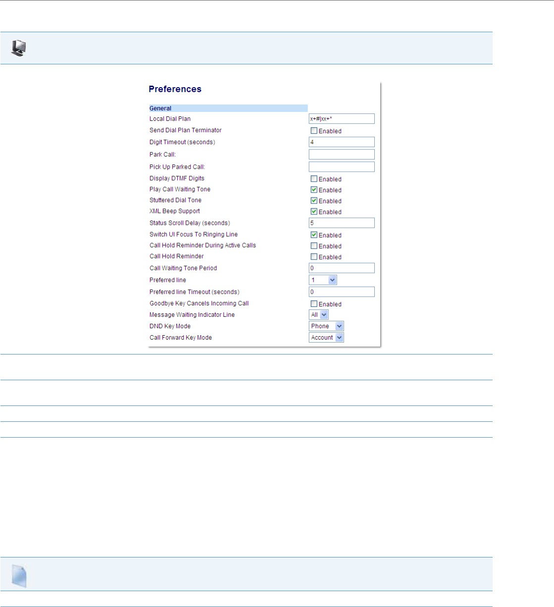
Operational Features
5-56 41-001343-02 REV04 – 05.2014
Filter Out Incoming DTMF Events
An Administrator can enter a parameter in the configuration files to suppress incoming DTMF playback. This new param-
eter called “suppress incoming dtmf playback” will suppress the playback of both SIP INFO and RFC2833 incoming
DTMF tones. The locally generated DTMF tones will still be played.
Configuring Suppress Incoming DTMF Playback
Use the following procedures to suppress incoming DTMF playback on the IP phone.
Aastra Web UI
1. Click on Basic Settings-> Preferences->General.
2. Enable the "Display DTMF Digits" field by checking the check box.
(Disable this field by unchecking the box). Default is disabled.
3. Click Save Settings to save your changes.
You must restart your IP phone for the changes to take effect.
4. Click on Operation->Reset.
5. In the “Restart Phone” field click Restart to restart the IP phone and apply the changes.
Configuration Files
For specific parameters you can set in the configuration files, see Appendix A, the section, “Filter Out Incoming DTMF Events” on pageA-144.

Operational Features
41-001343-02 REV04 – 05.2014 5-57
Call Waiting
The call waiting feature notifies a user on an active call on the phone, of a new incoming call. You can disable this call wait-
ing feature, so that the new incoming call is automatically rejected by the phone with a busy message. A User or Adminis-
trator can configure this feature.
If you disable call waiting on the phone, and the user is on a call, any further incoming calls will receive busy unless “Call
Forward Busy” or “Call Forward No Answer and Busy” is configured on the phone. It will then forward the call according to
the rule configured. The phone can only:
•transfer the currently active call
or
•accept transferred calls if there is no active calls.
If call waiting is disabled:
•on the 6757i CT bases, and the handset is currently on a call, all additional incoming calls are rejected on the handset.
•intercom calls are treated as regular incoming calls and are rejected.
•pre-dialing with live dialpad disabled still accepts incoming calls.
•the Missed Calls List does not get updated with details of calls.
•the Blind Transfer feature on the phone may not work if two calls are made to the phone at one time.
You can enable/disable call waiting on a global or per-line basis using the configuration files or the Aastra Web UI.
Configuring Call Waiting
Use the following procedures to configure the Call Waiting feature on the IP phone.
Configuration Files
For specific parameters you can set in the configuration files, see Appendix A, the section, “Call Waiting Settings” on pageA-64 or “SIP Per-Line Call
Waiting Setting” on pageA-73.
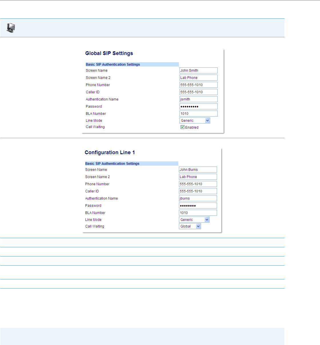
Operational Features
5-58 41-001343-02 REV04 – 05.2014
Call Waiting Tone
You can also enable or disable the playing of a short “call waiting tone" when there is an incoming call on your phone
using the “play call waiting tone” parameter. This feature is enabled by default. If you have Call Waiting enabled, and a
call comes into the line for which you are on an active call, a tone is audible to notify you of that incoming call.
A User or Administrator can configure this feature using the Aastra Web UI. An Administrator can also configure this fea-
ture using the configuration files.
Aastra Web UI
1. For global configuration, click on Advanced Settings->Global SIP->Basic SIP Authentication Settings.
Or, for per-line configuration, click on Advanced Settings->Line N (1-9)0->Basic SIP Authentication Settings.
Configure Global Call Waiting
2. The "Call Waiting" field is enabled by default. To disable call waiting on a global basis, uncheck this box.
Configure Per-Line Call Waiting
3. The "Call Waiting" field is set to “Global” by default. To enable call waiting for a specific line, select “enabled” from the list in this field. To dis-
able call waiting for a specific line, select “disabled” from the list in this field.
4. Click Save Settings to save your changes.
Note:
The Call Waiting Tone feature works only if Call Waiting is enabled.
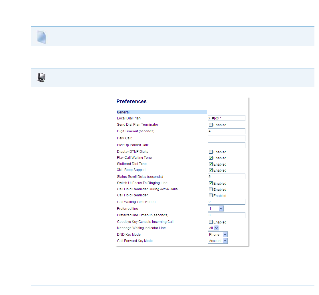
Operational Features
41-001343-02 REV04 – 05.2014 5-59
Configuring Call Waiting Tone
Use the following procedures to configure the Call Waiting Tone feature on the IP phone.
Call Waiting Tone Period
A User or Administrator can specify a specific time period (in seconds) for the call waiting tone to play at regular intervals
on an active call using the parameter “call waiting tone period”. A value of “0” is the default and plays the call waiting
tone only once on the active call. When the incoming caller hangs up, the call waiting tone stops on the existing active call.
You can enable or disable this feature in the configuration files or in the Aastra Web UI.
Configuration Files
For specific parameters you can set in the configuration files, see Appendix A, the section, “Call Waiting Settings” on pageA-64.
Aastra Web UI
1. Click on Basic Settings-> Preferences->General.
2. The "Play Call Waiting Tone" field is enabled by default. To disable this field, uncheck the box. This feature allows you to enable or disable
the call waiting tone on the IP phone.
Note:
The Call Waiting Tone feature works only if the “Call Waiting” tone field is enabled at the location Advanced Settings->Global SIP (or Line X)-
>Basic SIP Authentication Settings.
3. Click Save Settings to save your changes.
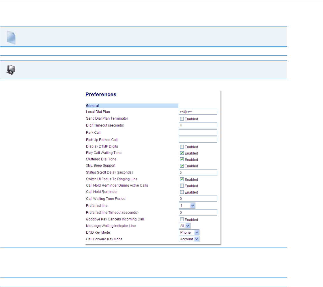
Operational Features
5-60 41-001343-02 REV04 – 05.2014
Configuring “Call Waiting Tone Period”
You use the following procedures to enable or disable “Call Waiting Tone Period”.
Configuration Files
For specific parameters you can set in the configuration files, see Appendix A, the section, “Call Waiting Settings” on pageA-64.
Aastra Web UI
1. Click on Basic Settings->Preferences->General.
2. In the "Call Waiting Tone Period" field,enter a time period, in seconds, that the call waiting tone will be audible on an active call when
another call comes in. Default is 0 seconds.
When enabled, the call waiting tone plays at regular intervals for the amount of time set for this parameter. For example, if set to “30” the call
waiting tone plays every 30 seconds. When set to “0”, the call waiting tone is audible only once on the active call
3. Click Save Settings to save your changes.
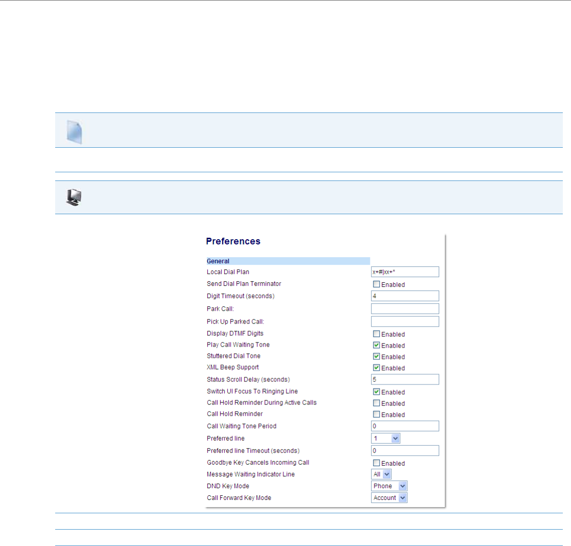
Operational Features
41-001343-02 REV04 – 05.2014 5-61
Stuttered Dial Tone
You can enable or disable the playing of a stuttered dial tone when there is a message waiting on the IP phone.
You can configure this feature using the configuration files and the Aastra Web UI.
Configuring Stuttered Dial Tone
Use the following procedures to configure stuttered dial tone on the IP phones.
Configuration Files
For specific parameters you can set in the configuration files for enabling/disabling stuttered dial tone, see Appendix A, the section, “Stuttered Dial
Tone Setting” on pageA-125.
Aastra Web UI
1. Click on Basic Settings->Preferences->General.
2. The "Stuttered Dial Tone" field is enabled by default. To disable this field, uncheck the box.
3. Click Save Settings to save your changes.
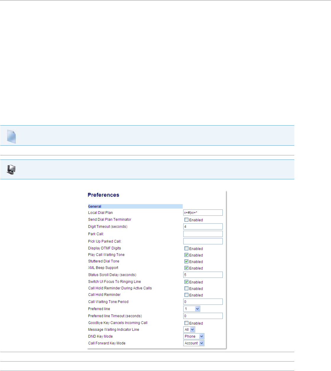
Operational Features
5-62 41-001343-02 REV04 – 05.2014
XML Beep Support
The IP phones have a feature that allows you to enable or disable a beep on the phone when it receives a status message
from an XML application. This beep can be turned ON or OFF using the Aastra Web UI, the configuration files, or in an
XML script. If you disable this feature, then no beep is heard when the XML application arrives to the phone.
If your System Administrator has set a value for this feature in a custom XML application or in the configuration files, the
value you set in the Aastra Web UI overrides the Administrator’s setting. Setting and saving the value in the Aastra Web
UI applies to the phone immediately.
Reference
For more information about enabling/disabling the XML Beep Support in an XML script, see “XML Customized Services”
on page5-239.
Configuring XML Beep Support
Use the following procedures to enable/disable XML Beep Support.
Configuration Files
For specific parameters you can set in the configuration files, see Appendix A, the section, “XML Settings” on pageA-114.
Aastra Web UI
1. Click on Basic Settings->Preferences->General.
2. The “XML Beep Support” field is enabled by default. To disable this field, uncheck the box.
3. Click Save Settings to save your changes.
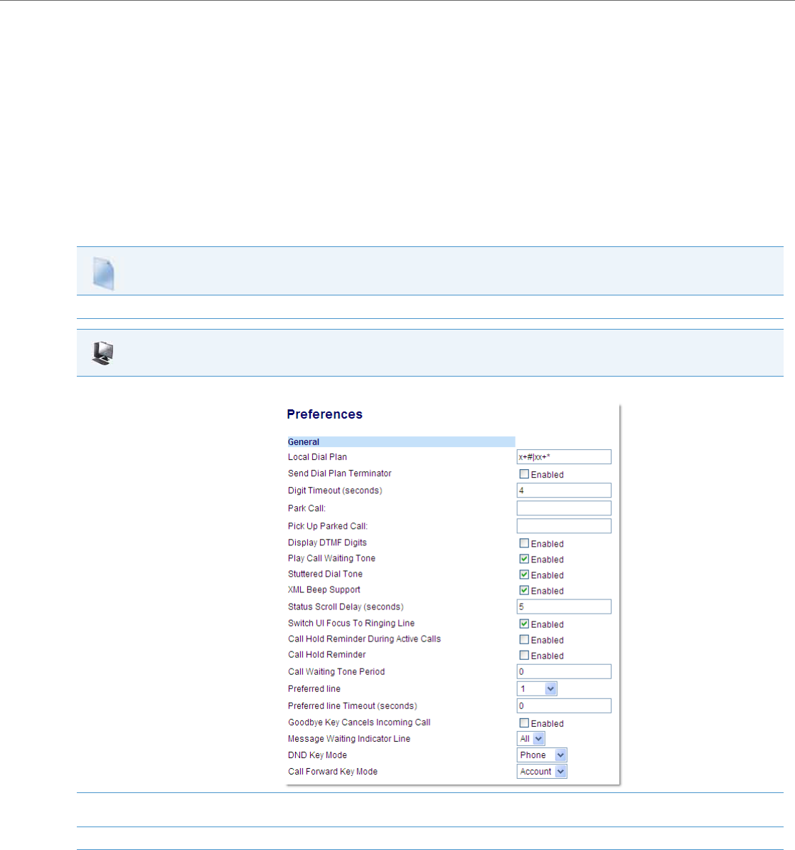
Operational Features
41-001343-02 REV04 – 05.2014 5-63
Status Scroll Delay
The IP phones have a feature that allows you to specify the time delay, in seconds, between the scrolling of each status
message (including XML status messages) on the phone. The default time is 5 seconds for each message to display before
scrolling to the next message. You can configure this option via the configuration files or the Aastra Web UI.
Reference
For more information about configuring the status scroll delay for XML status messages, see “XML Customized Services”
on page5-239.
Configuring Status Scroll Delay
Use the following procedures to configure Status Scroll Delay.
Configuration Files
For specific parameters you can set in the configuration files, see Appendix A, the section, “XML Settings” on pageA-114.
Aastra Web UI
1. Click on Basic Settings->Preferences->General.
2. In the “Status Scroll Delay (seconds)” field, enter a value, in seconds, that each XML status message displays on the phone. Default is 5 sec-
onds. Valid values are 1 to 25.
3. Click Save Settings to save your changes.
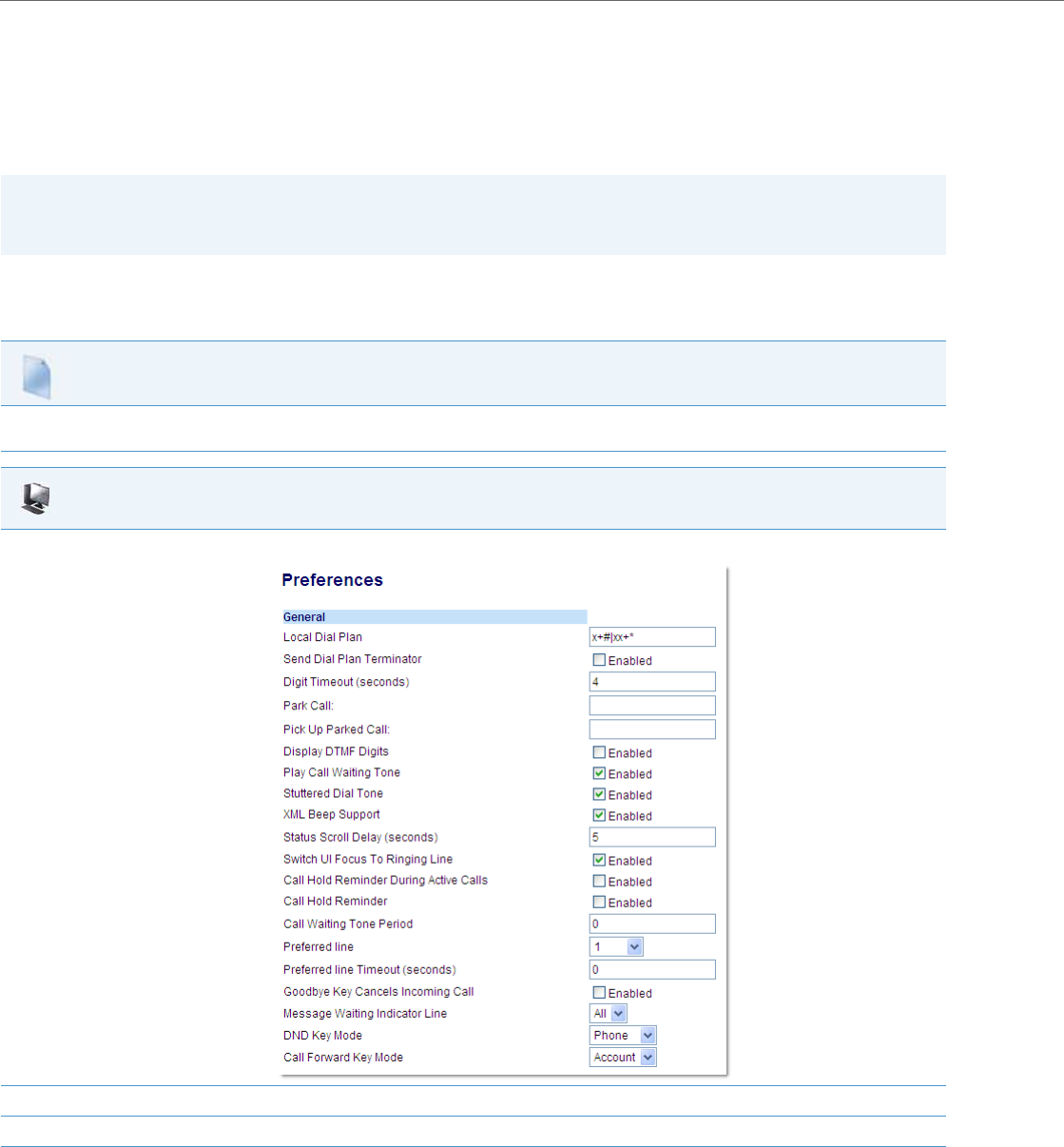
Operational Features
5-64 41-001343-02 REV04 – 05.2014
Switch Focus to Ringing Line
An Administrator or User can control the behavior of the phone when it receives an incoming call when it is already in a
connected call. By default, the phone switches focus to the ringing line to enable the user to see who is calling them.
You can turn off this functionality so that the phone now stays focused on the connected call. You can do this using the
“switch focus to ringing line” parameter in the configuration files or the Aastra Web UI.
Configuring “Switch Focus to Ringing Line”
You use the following procedures to enable or disable “Switch Focus to Ringing Line”.
Note:
If you configure the BLF/Xfer key(s) and/or Speeddial/Xfer key(s) on the phone, you can enable or disable the switching
of the user interface focus to ringing line while the phone is in the connected state.
Configuration Files
For specific parameters you can set in the configuration files for enabling disabling “Switch Focus to Ringing Line”, see Appendix A, the section, “Switch
Focus to Ringing Line” on pageA-122.
Aastra Web UI
1. Click on Basic Settings->Preferences->General.
2. The “Switch Focus to Ringing Line” field is enabled by default. To disable this field, uncheck the box.
3. Click Save Settings to save your changes.
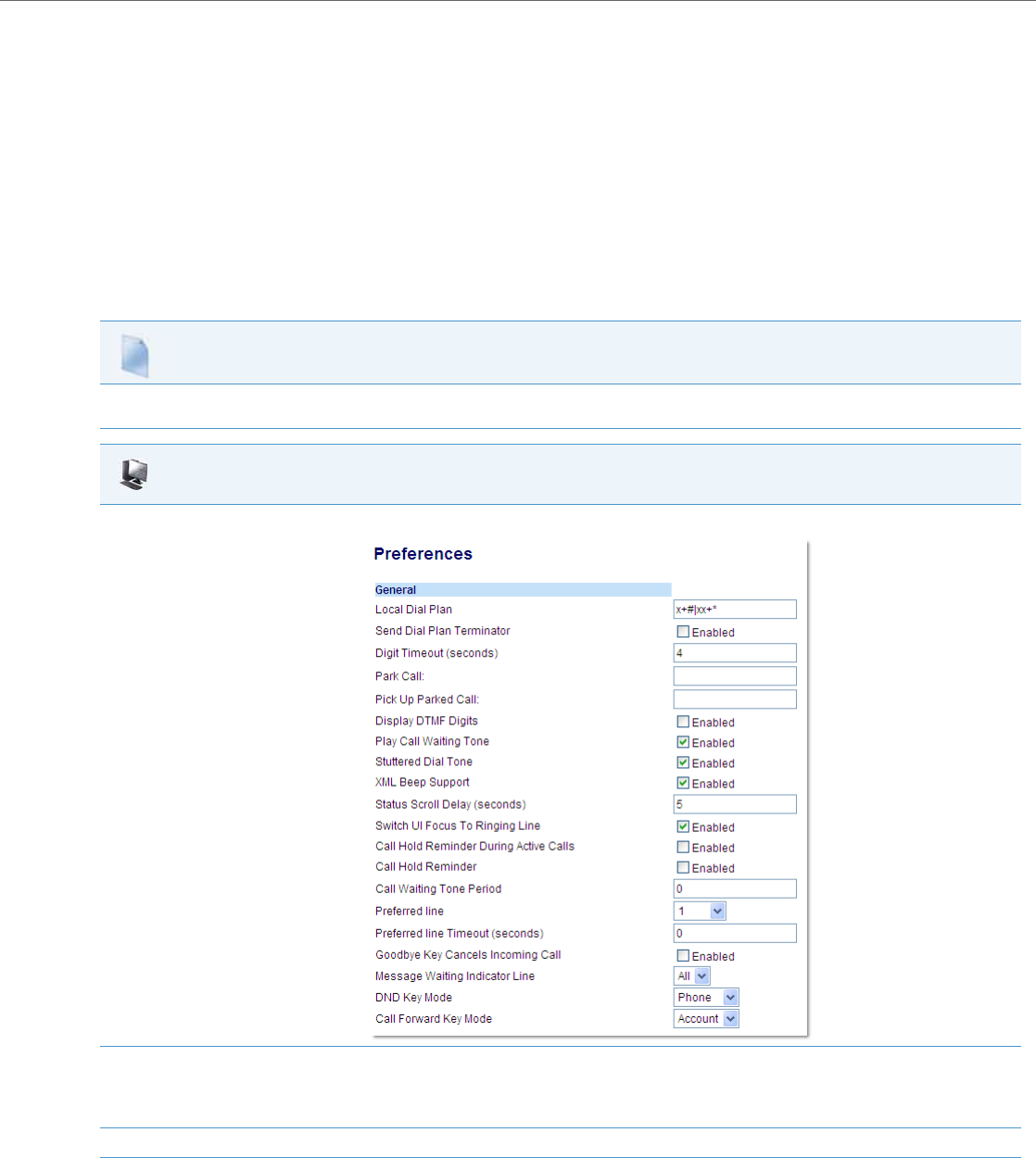
Operational Features
41-001343-02 REV04 – 05.2014 5-65
Call Hold Reminder During Active Calls
The IP phones allow a User or Administrator to enable or disable the ability for the phone to initiate a continuous reminder
tone on the active call when another call is on hold. For example, when this feature is enabled, and the call on Line 1 is on
hold, and then the User answers a call on Line 2 and stays on that line, a reminder tone is played in the active audio path
on Line 2 to remind the User that there is still a call on hold on Line 1.
When this feature is disabled, a ring splash is heard when the active call hangs up and there is still a call on hold.
Your can enable or disable this feature using the “call hold reminder during active calls” parameter in the configuration
files or in the Aastra Web UI.
Configuring “Call Hold Reminder During Active Calls”
You use the following procedure to enable or disable “Call Hold Reminder During Active Calls”.
Configuration Files
For the specific parameter you can set in the configuration files for enabling/disabling “Call Hold Reminder During Active Calls”, see Appendix A, the
section, “Call Hold Reminder Settings” on pageA-123.
Aastra Web UI
1. Click on Basic Settings->Preferences->General.
2. In the "Call Hold Reminder During Active Calls" field, enable this feature by placing a check mark in the box.
When this feature is enabled, a reminder tone is heard on the active call when another call is on hold. When disabled, a ring splash is heard
when the active call hangs up and there is still a call on hold.
3. Click Save Settings to save your changes.
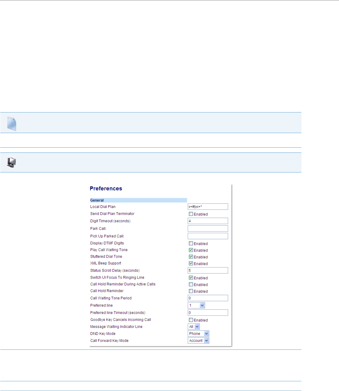
Operational Features
5-66 41-001343-02 REV04 – 05.2014
Call Hold Reminder (on Single Hold)
In previous releases, the call hold reminder ring splash was triggered when you hung up a call and there was at least one
other call on hold. The reminder ring splash timer started only when the active call hung up and there was still another
call on hold.
On the IP phones, a User or Administrator can enable or disable a feature that would start the reminder ring splash timer
as soon as you put a call on hold (even when no other calls are active on the phone). When enabled, the phone initiates a
reminder ring splash periodically for the single call on hold. When disabled, no reminder ring splash is audible.
You can enable or disable this feature using the “call hold reminder” parameter in the configuration files or in the Aastra
Web UI.
Configuring “Call Hold Reminder”
You use the following procedure to enable or disable “Call Hold Reminder”.
Configuration Files
For the specific parameter you can set in the configuration files for enabling/disabling “Call Hold Reminder”, see Appendix A, the section, “Call Hold
Reminder Settings” on pageA-123.
Aastra Web UI
1. Click on Basic Settings->Preferences->General.
2. The "Call Hold Reminder" field is disabled by default. To enable this feature, place a check mark in the box.
When this feature is enabled, the reminder ring splash timer starts as soon as you put a call on hold (even when no other calls are active on
the phone).The phone initiates a reminder ring splash periodically for the single call on hold. When disabled, no reminder ring splash is audi-
ble.
3. Click Save Settings to save your changes.

Operational Features
41-001343-02 REV04 – 05.2014 5-67
Call Hold Reminder Timer & Frequency
There are two parameters an Administrator can set on the IP Phones along with the “call hold reminder” and “call hold
reminder during active calls” parameters:
•call hold reminder timer
•call hold reminder frequency
These parameters specify the time delay and time frequency of the ring splash that sounds when you are on an active call
and have placed another call on hold. You can configure these parameters using the configuration files only.
Configuring “Call Hold Reminder Timer”
You use the following procedure to configure the “Call Hold Reminder Timer”.
Configuring “Call Hold Reminder Frequency”
You use the following procedure to configure the “Call Hold Reminder Frequency”.
Notes:
•You must enable the “call hold reminder” and/or “call hold reminder during active calls” parameter(s) for the
above parameters to work.
•A value of “0” for the “call hold reminder timer” parameter disables the call hold reminder feature.
•A value of “0” for the “call hold reminder frequency” parameter prevents additional rings.
Configuration Files
For the specific parameter you can set in the configuration files for setting the “Call Hold Reminder Timer”, see Appendix A, the section, “Call Hold
Reminder Settings” on pageA-123.
Configuration Files
For the specific parameter you can set in the configuration files for setting the “Call Hold Reminder Frequency”, see Appendix A, the section, “Call Hold
Reminder Settings” on pageA-123.

Operational Features
5-68 41-001343-02 REV04 – 05.2014
Preferred Line and Preferred Line Timeout
An Administrator or User can define a preferred line as well as a preferred timeout. If a preferred line is selected, after a
call ends (incoming or outgoing), the display switches back to the preferred line. Next time you go off-hook, you pickup
on the preferred line. You can specify the number of seconds it takes for the phone to switch back to the preferred line
using the “preferred timeout” parameter.
An Administrator can configure the “preferred line” and the “preferred timeout” parameters using the configuration
files or the Aastra Web UI. A User can configure these parameters using the Aastra Web UI only.
The following table provides the behavior of the preferred line focus feature with other features on the phone.
Configuring the Preferred Line and Preferred Line Timeout
You use the following procedures to configure the Preferred Line and the Preferred Line Timeout on the IP Phones.
Phone Feature Preferred Line Behavior
Call Return The phone switches back to the focused line immediately after the call ends.
Speeddial The line is already specified when the speeddial is created. The phone switches back immediately after the call ends.
Conference For incoming calls, the phone switches back immediately after the call ends.
Transfer For incoming or outgoing calls, the current behavior is that the same line used to transfer the call does not change. For incom-
ing calls, the phone switches back immediately after the call transfers.
BLF The phone switches back immediately after the call ends.
Park The phone switches back immediately after the call ends.
Voicemail The phone switches back immediately after the call ends.
Redial The phone switches back immediately after the call ends.
Dialing For incomplete dialing on a non-preferred line, the focus does not change if some digits are entered.
If no digits are entered or digits were cleared, the focus changes to preferred line after the time out has passed without activi-
ties.
Caller ID If the "Switch UI Focus To Ringing Line" parameter is disabled, the User is able to see the Caller ID when the phone switches the
focus to the ringing line.
Factory Default Factory default and recovery mode clears the "preferred line" and "preferred line timeout" parameters, and the phone operates
in a non-preferred line mode.
Notes:
•If you specify a value of “0” for the preferred line parameter, it disables the preferred line focus feature.
•If you specify a value of “0” for the preferred line timeout parameter, the phone returns the line to the preferred line
immediately.
Configuration Files
For specific parameters you can set in the configuration files for configuring the Preferred Line and Preferred Line Timeout, see Appendix A, the sec-
tion, “Preferred Line and Preferred Line Timeout” on pageA-124.
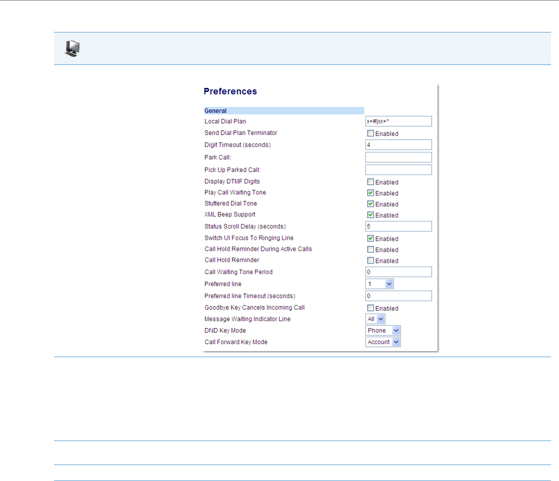
Operational Features
41-001343-02 REV04 – 05.2014 5-69
Use the following parameters to configure preferred line focus using the Aastra Web UI.
Goodbye Key Cancels Incoming Call
You can configure the Goodbye key to drop active calls or ignore incoming calls using the “goodbye cancels incoming
call” parameter or through the Web UI. This parameter controls the behavior of the goodbye key when the phone is on an
active call and a second call is presented to the phone.
How it Works
When you enable this parameter (1 = enable in the configuration files), which is the default, the Goodbye key rejects the
incoming call. When you disable this parameter (0 = disable in the configuration files), the Goodbye key hangs up the
active call.
Aastra Web UI
1. Click on Basic Settings->Preferences->General.
2. In the “Preferred Line” field, select a preferred line to switch focus to after incoming or outgoing calls end on the phone. Valid values are:
•None (disables the preferred line focus feature)
•1 to 9
Default is 1.
For example, if you set the preferred line to “1”, when a call (incoming or outgoing) ends on the phone (on any line), the phone switches
focus back to Line 1.
3. In the “Preferred Line Timeout” field, enter the amount of time, in seconds, that the phone switches back to the preferred line after a call
(incoming or outgoing) ends on the phone, or after a duration of inactivity on an active line. Default is 0. Valid values are 0 to 999.
4. Click Save Settings to save your changes.
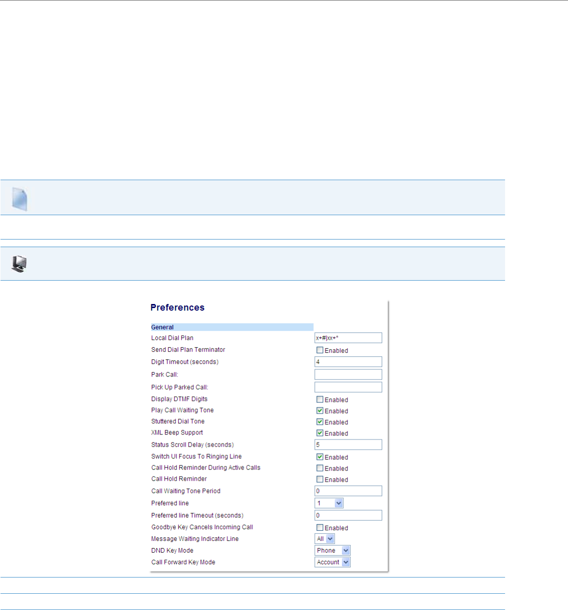
Operational Features
5-70 41-001343-02 REV04 – 05.2014
For 8 and 11-line LCD phones
If you enable this parameter, and the phone receives another call when an active call is already present, the phone dis-
plays softkey 1 as “answer” and softkey 2 as “ignore”. You can press the required softkey as applicable.
For 3-line LCD phones
If you disable this parameter, and the phone receives another call when an active call is already present, the “ignore”
option displays in the LCD window. The phone will ignore the incoming call if you press the DOWN arrow navigation key.
The phone will hang up on the active call if you press the Goodbye key.
You can set this parameter using the configuration files or the Aastra Web UI.
Configuring the Goodbye Key to Cancel Incoming Calls
Use the following procedures to configure the behavior of the Goodbye Key on the IP phone.
Configuration Files
For specific parameters you can set in the configuration files for enabling/disabling the behavior of the Goodbye Key, see Appendix A, the section,
“Goodbye Key Cancels Incoming Call” on pageA-125.
Aastra Web UI
1. Click on Basic Settings->Preferences->General.
2. Enable or disable the "Goodbye Key Cancels Incoming Call" field by checking or unchecking the check box.
3. Click Save Settings to save your changes.

Operational Features
41-001343-02 REV04 – 05.2014 5-71
Configurable Status Code on Ignoring Incoming Calls
When a user presses the “Ignore” key on the phones during an incoming call, the phone rejects the incoming call with a
status code of “486 Busy Here”. The IP phones allow an administrator to configure this status code. You can configure the
status code using the configuration files only.
Use the following parameter to configure a status code when ignoring incoming calls:
•sip ignore status code
Configuring Status Codes on Ignoring Incoming Calls
You can use the following procedure to set the status code sent in the response when a user presses the “Ignore” key.
Message Waiting Indicator Line
A User or Administrator can configure the Message Waiting Indicator (MWI) to illuminate for a specific line or for all lines.
For example, if you configure the MWI LED on line 3 only, the LED illuminates if a voicemail is pending on line 3. If you con-
figure the MWI LED for all lines, the LED illuminates if a voicemail is pending on any line on the phone (lines 1 through 9).
A User can configure the MWI using the Aastra Web UI only. An Administrator can configure the MWI on single or all lines
using the configuration files or the Aastra Web UI.
Configuring Message Waiting Indicator (MWI)
Use the following procedures to configure MWI on the IP phone.
Note:
Valid status codes are based on RFC3261.
Configuration Files
For the specific parameter you can set in the configuration files, see Appendix A, the section, “Status Code on Ignoring Incoming Calls” on pageA-122.
Configuration Files
For specific parameters you can set in the configuration files, see Appendix A, the section, “Message Waiting Indicator Settings” on pageA-126.
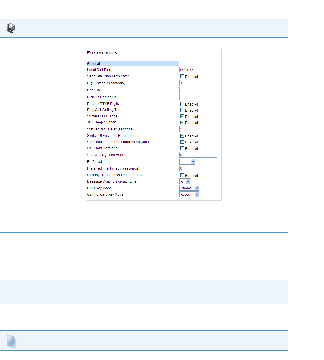
Operational Features
5-72 41-001343-02 REV04 – 05.2014
Customizable Message Waiting Indicator (MWI) Request URI
In Release 3.1 and up, an Administrator can enter a parameter in the configuration files to customize the request-URI for
MWI feature subscription. This parameter is called “sip linex mwi request uri”.
This feature can be set on a per-line basis using the configuration files only.
Configuring Message Waiting Indicator (MWI) Request URI
Use the following procedure to configure an MWI request URI on the IP phone.
Aastra Web UI
1. Click on Basic Settings-> Preferences->General.
2. In the “Message Waiting Indicator Line” field, select a single line from 1 to 9, or select “All” for all lines. If you select a single line, the MWI
illuminates when a voicemail message is pending on that line. If you select all lines, the MWI illuminates when a voicemail message is pend-
ing on any line from 1 to 9.
3. Click Save Settings to save your changes.
Note:
“Sip Explicit MWI Subscription” must be enabled to use this feature. For more information about the Sip Explicit MWI
Subscription” parameter, see “Advanced SIP Settings (optional)” on page4-69.
Configuration Files
For the specific parameter you can set in the configuration files, see Appendix A, the section, “Message Waiting Indicator Settings” on pageA-126.

Operational Features
41-001343-02 REV04 – 05.2014 5-73
DND Key Mode
The IP phones have a feature you can enable called "Do not Disturb (DND). An Administrator or User can set “do not dis-
turb” based on the accounts on the phone (all accounts or a specific account). You can set specific modes for the way you
want the phone to handle DND. The three modes you can set on the phone for DND are:
•Account
•Phone
•Custom
An Administrator or User can set the DND mode using the Aastra Web UI at the path Basic Settings->Preferences->General-
>DND Key Mode. An Administrator can also set the DND Key Mode using the configuration files.
Reference
For more information about how DND works and how you can use it on the phones, see the section, “Do Not Disturb
(DND)” on page5-154.
Configuring the DND Key Mode
Use the following procedures to set the DND Key Mode on the phone.
Note:
You must configure a DND key on the phone to use this feature.
Configuration Files
For specific parameters you can set in the configuration files, see Appendix A, the section, “DND Key Mode Settings” on pageA-127.
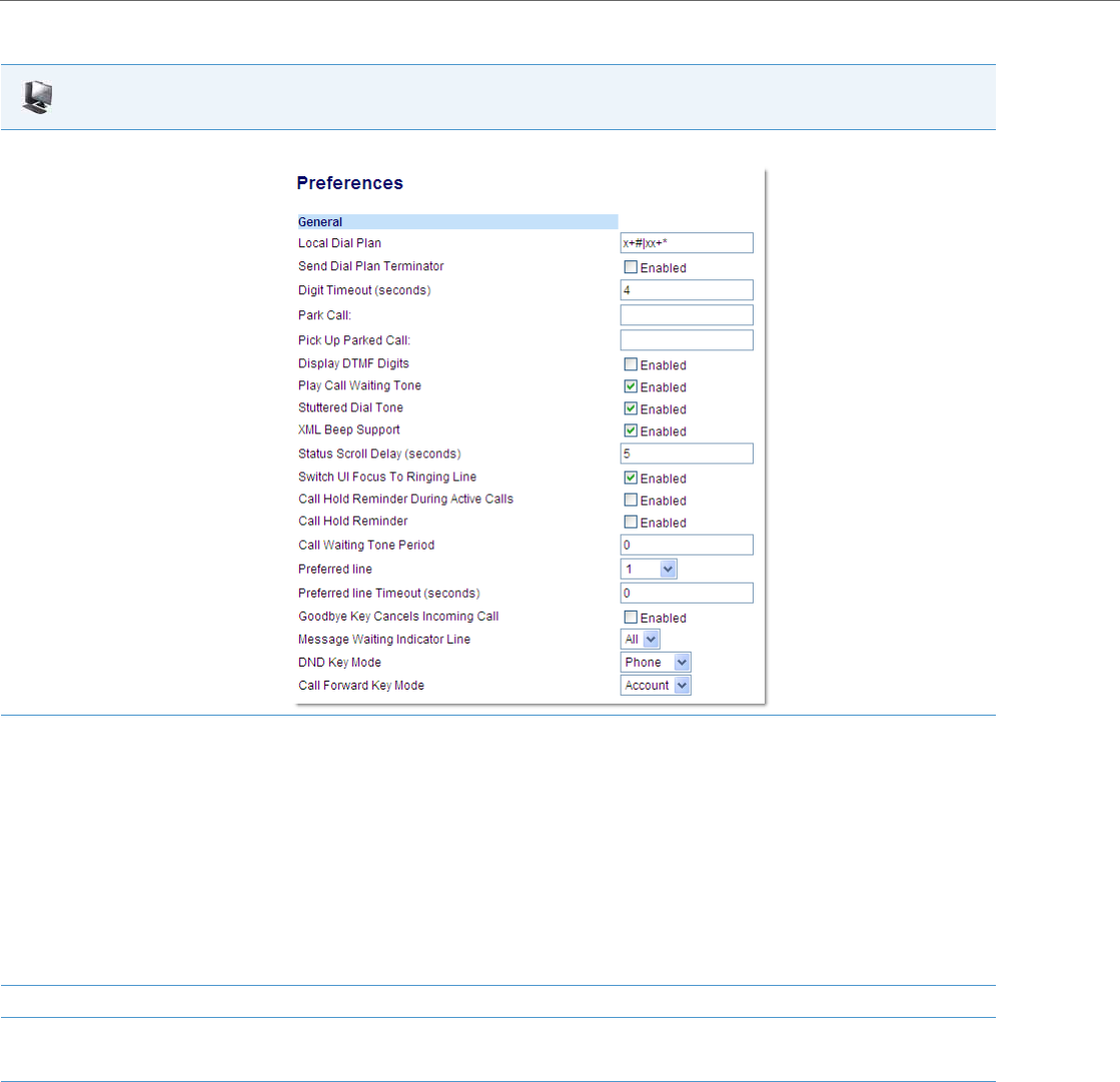
Operational Features
5-74 41-001343-02 REV04 – 05.2014
Reference
For more information, see the section, “Do Not Disturb (DND)” on page5-154.
Aastra Web UI
1. Click on Basic Settings->Preferences->General.
2. In the “DND Key Mode” field, select a “do not disturb” (DND) mode to use on the phone. Valid values are:
•Account
Sets DND for a specific account. DND key toggles the account in focus on the IP Phone UI, to ON or OFF.
•Phone
Sets DND ON for all accounts on the phone. DND key toggles all accounts on the phone to ON or OFF.
•Custom
Sets the phone to display custom screens after pressing the DND key, that list the account(s) on the phone. The user can select a specific
account for DND, turn DND ON for all accounts, or turn DND OFF for all accounts.
The default is Phone.
Notes:
•If there is only one account configured on the phone, then the mode setting is ignored and the phone behaves as if the mode was set to
“Phone”.
•Using the Aastra Web UI, if you change the DND Key Mode to “phone”, all accounts synchronize to the current setting of Account 1.
3. Configure a DND key on the phone using the procedures in the section, “Do Not Disturb (DND)” on page5-154.
4. Click Save Settings to save your changes.
The change takes effect immediately without a reboot.

Operational Features
41-001343-02 REV04 – 05.2014 5-75
Call Forward Mode
Call Forward (CFWD) on the IP phone allows incoming calls to be forwarded to another destination. The phone sends the
SIP message to the SIP proxy, which then forwards the call to the assigned destination.
An Administrator or User can configure CFWD on the phone-side by setting a mode for the phone to use (Account,
Phone, or Custom). Once the mode is set, you can use the IP Phone UI to use the CFWD feature at Options->Call Forward or
by pressing a configured Call Forward softkey/programmable key/extension module key.
The following describes the behavior for each CFWD mode.
•Account mode - The account mode allows you to configure CFWD on a per account basis. Pressing a configured CFWD
key applies to the account in focus.
•Phone mode - The Phone mode allows you to set the same CFWD configuration for all accounts (All, Busy, and/or No
Answer). When you configure the initial account, the phone applies the configuration to all other accounts. (In the Aas-
tra Web UI, only the account you configured is enabled. All other accounts are grayed out but set to the same configura-
tion.) Using the Aastra Web UI, if you make changes to that initial account, the changes apply to all accounts on the
phone.
•Custom mode - The Custom mode allows you to configure CFWD for a specific account or all accounts. You can config-
ure a specific mode (All, Busy, and/or No Answer) for each account independently or all accounts. On the 3-line LCD
phones and the 6867i, you can set all accounts to ALL On or ALL Off. On the 8 and 11-Line LCD phones and the 6739i,
you can set all accounts to All On, All Off, or copy the configuration for the account in focus to all other accounts using
a CopytoAll softkey.
The states you can set for Call Forward are All, Busy, No Answer. You can enable different call forwarding rules/modes
independently (for example, you can set different phone numbers for Busy, All, and NoAns modes and then turn them
on/off individually. The behavior of these states is dependent on the mode (account, phone, or custom) you configure on
the phone.
Reference
For more information about how Call Forwarding works and how you can use it on the IP Phones, see “Call Forwarding” on
page5-190.
Configuring Call Forward Key Mode
Use the following procedures to set the Call Forward key mode on the IP phones.
Note:
If there is only one account configured on the phone, then the mode setting is ignored and the phone behaves as if the
mode was set to “Phone”.
Configuration Files
For specific parameters you can set in the configuration files, see Appendix A, the section, “Call Forward Key Mode Settings” on pageA-111.
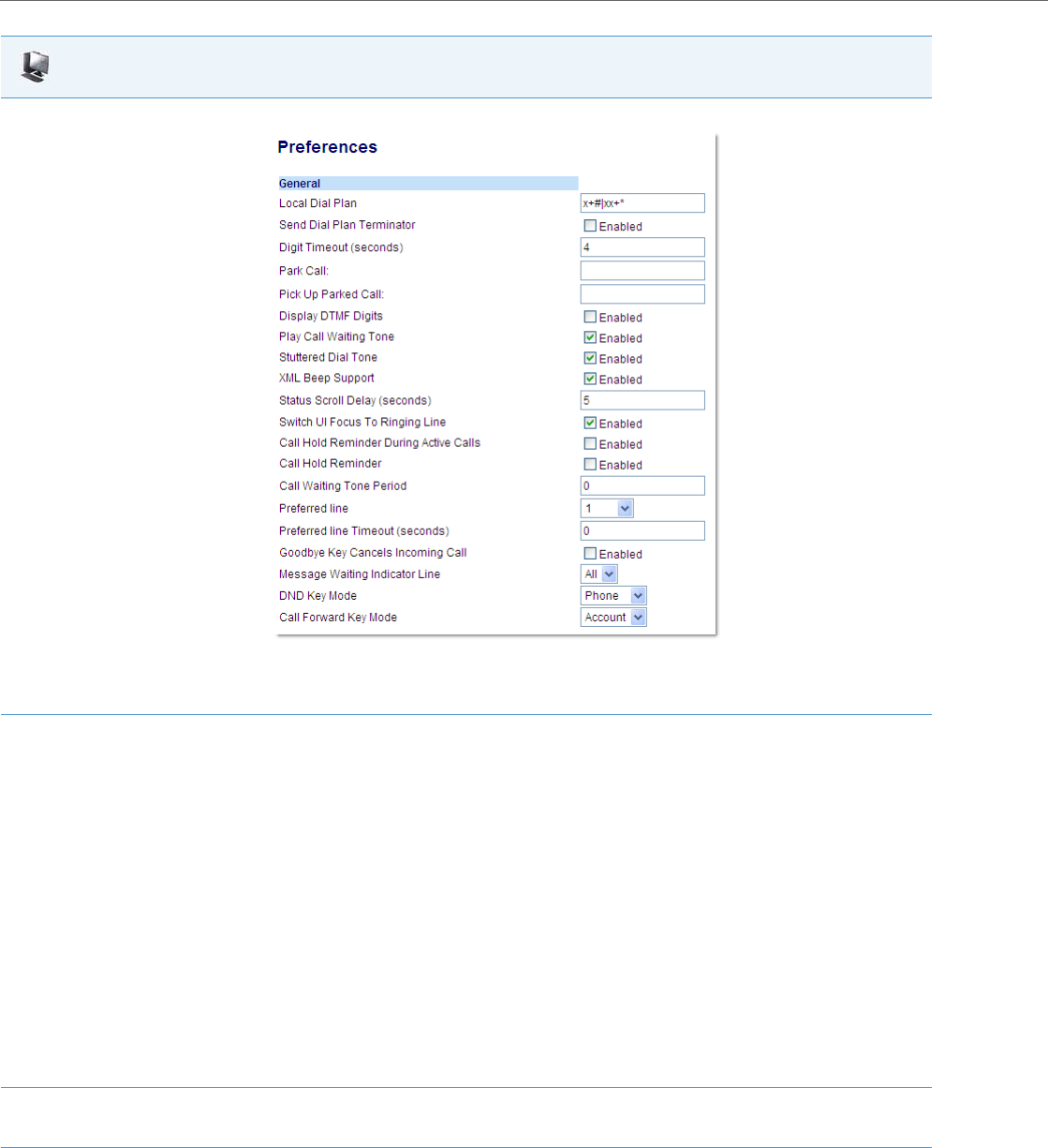
Operational Features
5-76 41-001343-02 REV04 – 05.2014
Reference
For more information, see the section, “Call Forwarding” on page5-190.
Aastra Web UI
1. Click on Basic Settings->Preferences->General.
Note:
If there is no CFWD key configured on the phone or it is removed, you can still configure Call Forwarding via the IP Phone UI at the path
Options->Call Forward.
2. In the “Call Forward Key Mode” field, select a call forward mode to use on the phone. Valid values are:
•Account
The account mode allows you to configure CFWD on a per account basis. Pressing a configured CFWD key applies to the account in focus.
•Phone
The Phone mode allows you to set the same CFWD configuration for all accounts (All, Busy, and/or No Answer). When you configure the
initial account, the phone applies the configuration to all other accounts. (In the Aastra Web UI, only the account you configured is ena-
bled. All other accounts are grayed out but set to the same configuration.) Using the Aastra Web UI, if you make changes to that initial
account, the changes apply to all accounts on the phone.
•Custom
The Custom mode allows you to configure CFWD for a specific account or all accounts. You can configure a specific state (All, Busy, and/or
No Answer) for each account independently or all accounts. On the 3-Line LCD phones and the 6867i, you can set all accounts to ALL On
or ALL Off.
On the 8 and 11-Line LCD phones and the 6739i, you can set all accounts to All On, All Off, or copy the configuration for the account in
focus to all other accounts using a CopytoAll softkey.
The default is Account.
Notes:
•If there is no CFWD key configured on the phone or it is removed, you can still set the CFWD modes via the IP Phone UI at the path Options-
>Call Forward.
•If there is only one account configured on the phone, then the mode setting is ignored and the phone behaves as if the mode was set to
“Phone”.
•When configuring a CFWD state (All, Busy, No Answer) for an account, you must configure a CFWD number for that state in order for the
state to be enabled.
3. Click Save Settings to save your changes.
The change takes effect immediately without a reboot.

Operational Features
41-001343-02 REV04 – 05.2014 5-77
Link Layer Discovery Protocol for Media Endpoint Devices (LLDP-MED) and
Emergency Location Identification Number (ELIN)
The IP Phones support Link Layer Discovery Protocol for Media Endpoint Devices (LLDP-MED). LLDP-MED is designed to
allow for things such as:
•Auto-discovery of LAN policies (such as VLAN, Layer 2 Priority and Diffserv settings) leading to "plug and play" network-
ing.
•Extended and automated power management of Power over Ethernet endpoints.
•Inventory management, allowing network administrators to track their network devices, and determine their character-
istics (manufacturer, software and hardware versions, serial / asset number).
On the IP Phones, LLDP-MED performs the following:
•Supports the MAC/PHY configuration (e.g. speed rate/duplex mode).
•Supports VLAN info from the network policy; this takes precedence over manual settings.
•Allows you to enable/disable LLDP-MED if required.
•Allows you to configure time interval between successive LLDP Data Unit (LLDPDU) frames.
•Allows LLDP packets to be received from the LAN port.
•Allows the phone to use the location information, Explicit Congestion Notification (ECN) Emergency Location Identifica-
tion Number (ELIN), sent by the switch, as a caller ID for making emergency calls.
Aastra IP Phones have a 32 second time-out for listening to LLDP-MED responses when the phone is booting up. If LLDP-
MED responses are received after this initial listening period, the phone will ignore the response. Administrators can con-
figure this time-out interval using the "lldp startinterval" parameter. This parameter is only valid during the phone
bootup process and it will control the LLDP-MED time-out interval where the phone sends LLDP-MED advertisements and
listens for the LLDP-MED responses from the switch before proceeding to the DHCP stage. The default value of this param-
eter is 32 seconds.
Administrators can also now configure the optional Link Layer Discovery Protocol for Media Endpoint Devices (LLDP-MED)
Inventory Management type-length-value (TLV) sets. Using the “lldp optional inventory management tlv” parameter,
Administrators can configure the phone to either send all Inventory Management TLV (1) sets or to send none (0) . The
default for this parameter is (1).
The following table identifies the configuration parameters for LLDP and ELIN and which method you can use to configure
each parameter. This table also indicates whether the parameters can be configured by an Administrator, a User, or both.
Note:
If the phone receives location information in ECN ELIN format (10 to 25 numeric string), the phone replaces the caller
ID SIP header with the ECN ELIN value and the SIP URI does not change. The phone determines if this is an emergency
number by checking the emergency dial plan configured on the phone.
Parameter Method of Configuration Who Can Configure
lldp Configuration Files Administrator
lldp interval Configuration Files Administrator
use lldp elin Configuration Files Administrator
lldp startinterval Configuration Files Administrator
lldp optional inventory management tlv Configuration Files Administrator
LLDP Support IP Phone UI Administrator
LLDP Aastra Web UI Administrator
LLDP Packet Interval Aastra Web UI Administrator
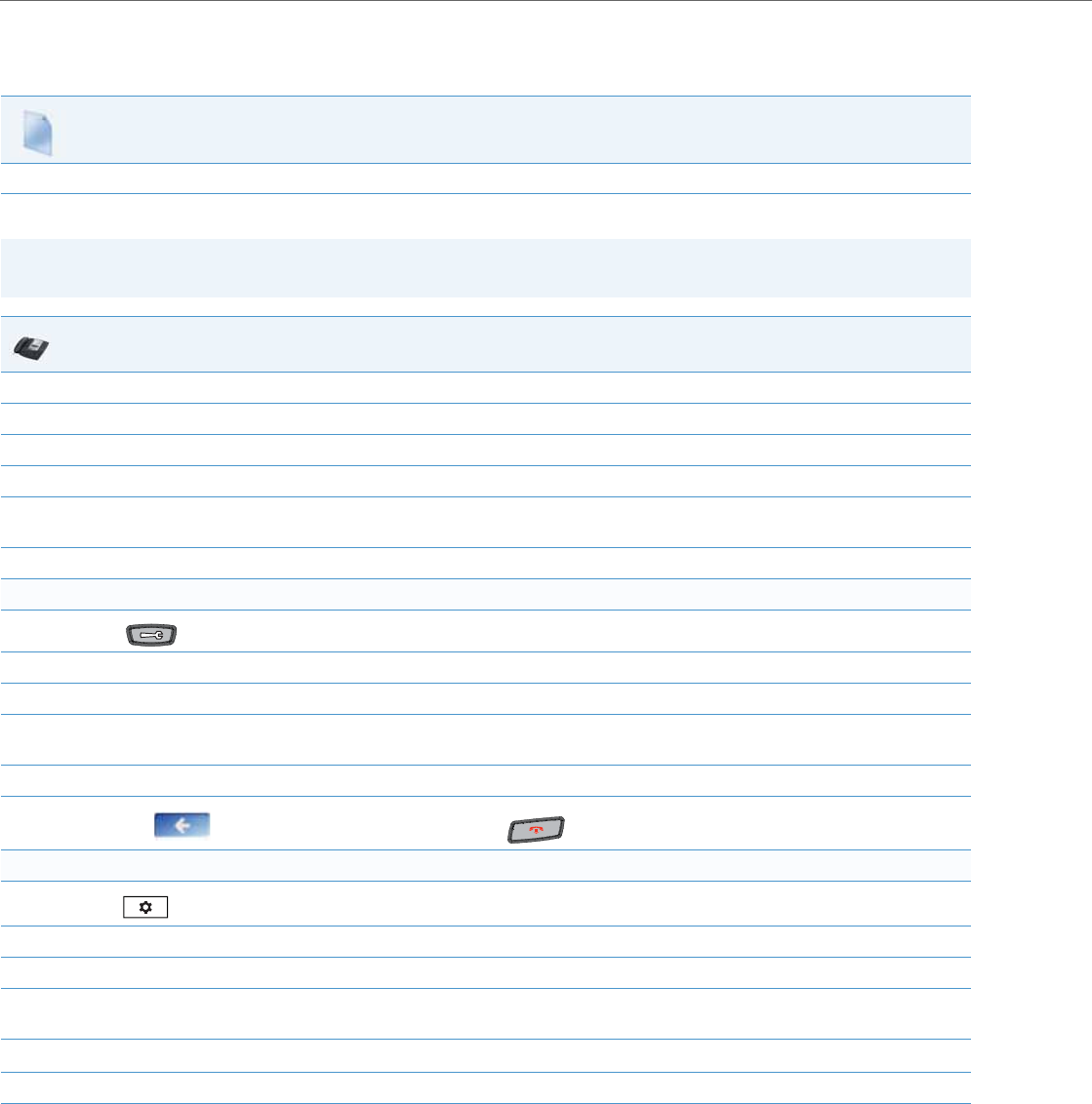
Operational Features
5-78 41-001343-02 REV04 – 05.2014
Configuring LLDP-MED and ELIN
Use the following procedures to configure LLDP-MED and ELIN on the IP phones.
Use the following procedure to enable/disable LLDP-MED using the IP Phone UI.
Configuration Files
For specific parameters you can set in the configuration files, see Appendix A, the section, “LLDP-MED and ELIN Settings” on pageA-112.
Note:
You cannot configure the “LLDP Interval” or the “Use LLDP ELIN” parameters via the IP Phone UI.
IP Phone UI
1. Press Options, and then select Administrator Menu.
2. Select Network Settings.
3. Select Ethernet & VLAN.
4. Select LLDP Support.
5. Press CHANGE to toggle the LLDP setting to Enabled or Disabled.
This field enables or disables Link Layer Discovery Protocol for Media Endpoint Devices (LLDP-MED) on the IP Phone.
6. Press DONE to save the change.
For the 6739i:
1. Press on the phone to enter the Options List.
2. Press the <Advanced> and enter your Administrator password using the pop-up keyboard.
3. Press the <Network> button, navigate to the second page and press <Ethernet & VLAN>.
4. Navigate to the second page and press the button beside <LLDP Support>.
This option enables or disables Link Layer Discovery Protocol for Media Endpoint Devices (LLDP-MED) on the IP Phone.
5. Press the <Enable> button the enable the feature.
6. Press the to return to the previous menu or press the to return to the idle screen.
For the 6867i:
1. Press to enter the Options List.
2. Press the Advanced softkey.
3. Enter the Administrator password using the keypad. Default is “22222”.
4. Select Network > LLDP.
This option enables or disables Link Layer Discovery Protocol for Media Endpoint Devices (LLDP-MED) on the IP Phone.
5. Use the 5 and 2 keys enable or disable the feature.
6. Press the Save softkey.
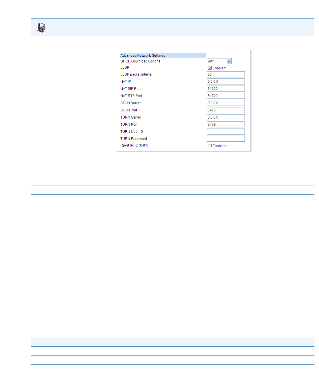
Operational Features
41-001343-02 REV04 – 05.2014 5-79
Use the following procedure to configure LLDP-MED using the Aastra Web UI:
Incoming/Outgoing Intercom with Auto-Answer and Barge In
The Intercom feature allows you to press the configured Intercom button on the IP phone and then enter the number you
want to call to initiate an intercom call. Intercom calls can be controlled either locally (phone-side) or by the SIP server
(server-side).
You can configure incoming and outgoing intercom calls on all phone models. A User can configure incoming intercom
calls only.
Outgoing Intercom Calls
On outgoing intercom calls, an available unused line is found when the Icom button is pressed. Since this line has no con-
figuration, the phone applies an existing configuration ("Outgoing Intercom Settings", Line, default is Line 1) to this line in
preparation for placing the intercom call. For example, an outgoing intercom call can use the configuration of line 1 but
places the actual intercom call using line 9. Only an Administrator can configure outgoing intercom calls.
A phone-side Intercom call indicates the phone is responsible for telling the recipient that an intercom call is being
placed, while a server-side intercom call means the SIP server is responsible for informing the recipient. Server-side calls
require additional configuration of a prefix code. After pressing the Icom button and entering the number to call, the
phone automatically adds the prefix to the called number and sends the outgoing call via the server.
For outgoing intercom calls, an administrator can configure the following parameters:
Aastra Web UI
1. Click on Advanced Settings->Network->Advanced Network Settings.
2. The “LLDP” field is enabled by default. To disable LLDP, click the check mark in the box to clear the check mark.
3. In the “LLDP Packet Interval” field, enter the time, in seconds, between the transmission of LLDP Data Unit (LLDPDU) packets.
The value of zero (0) disables this parameter. Valid values are 0 to 2147483647. Default is 30.
4. Click Save Settings to save your changes.
Configuration File Parameters Web UI Parameters
•sip intercom type •Type)
•sip intercom prefix code •Prefix Code
•sip intercom line •Line

Operational Features
5-80 41-001343-02 REV04 – 05.2014
Incoming Intercom Calls
You can configure how the phone handles incoming intercom calls. You can receive incoming intercom calls whether or
not there are active calls on the phone. The way the phone handles the call depends on the incoming intercom call con-
figuration. The following paragraphs describe the configuration parameters for incoming intercom calls.
Microphone Mute
You can mute or unmute the microphone on the IP phone for intercom calls made by the originating caller. If you want
to mute the intercom call, you enable this feature. If you want to unmute (or hear the intercom call), you disable this fea-
ture.
Auto-Answer/Play Warning Tone
The auto-answer feature on the IP phone allows you to enable or disable automatic answering for an Intercom call. If
“Auto-Answer” is enabled, the phone automatically answers an incoming intercom call. If “Play Warning Tone” is also
enabled, the phone plays a tone to alert the user before answering the intercom call. If “Auto-Answer” is disabled, the
phone treats the incoming intercom call as a normal call.
The IP phone recognizes if an incoming call is an intercom auto-answer call if the SIP INVITE includes one of the follow-
ing:
•A “Call-Info” header containing “answer-after=0”.
•An “Alert-Info” header containing “info=alert-autoanswer”.
•An “Alert-Info” header containing “Auto Answer” AND the“To” header containing “intercom=true”.
–When the IP phones recognize this third type of incoming intercom call, the call will automatically be answered and
the call’s audio will be played through the IP phone’s speaker (i.e. the user’s audio preferences will be ignored).
“Delay” before Auto-Answer
The IP Phones include support for the "delay" parameter (in the Alert-Info header, used in conjunction with info=alert-
autoanswer) in order to facilitate auto-answer functionality. When present, the value of the "delay" parameter specifies
the length of time in seconds an IP phone rings before a call is auto-answered. If this value of the "delay" parameter set to
0 (delay=0), then an incoming call is immediately auto-answered. The absence of the parameter is considered as ring for-
ever.
In order for the delay functionality to operate, you must first enable Auto-Answer on the IP Phone.
Allow Barge In
You can configure whether or not the IP phone allows an incoming intercom call to interrupt an active call. The “sip
intercom allow barge in” parameter controls this feature. When you enable the sip intercom allow barge in parameter
(1 = enable in the configuration files), which is the default value, an incoming intercom call takes precedence over any
active call, by placing the active call on hold and automatically answering the intercom call. When you disable this
parameter (0 = disable in the configuration files), and there is an active call, the phone treats an incoming intercom call
like a normal call and plays the call warning tone. You can set this parameter using the configuration files or the Aastra
Web UI.
For incoming intercom calls, an administrator or user can configure the following parameters:
Note:
To configure outgoing intercom calls using these parameters, see “Configuring Intercom Calls Settings” on page5-81.
Configuration File Parameters Web UI Parameters
sip allow auto answer Auto-Answer
sip intercom mute mic Microphone Mute
sip intercom warning tone Play Warning Tone
sip intercom allow barge in Barge In
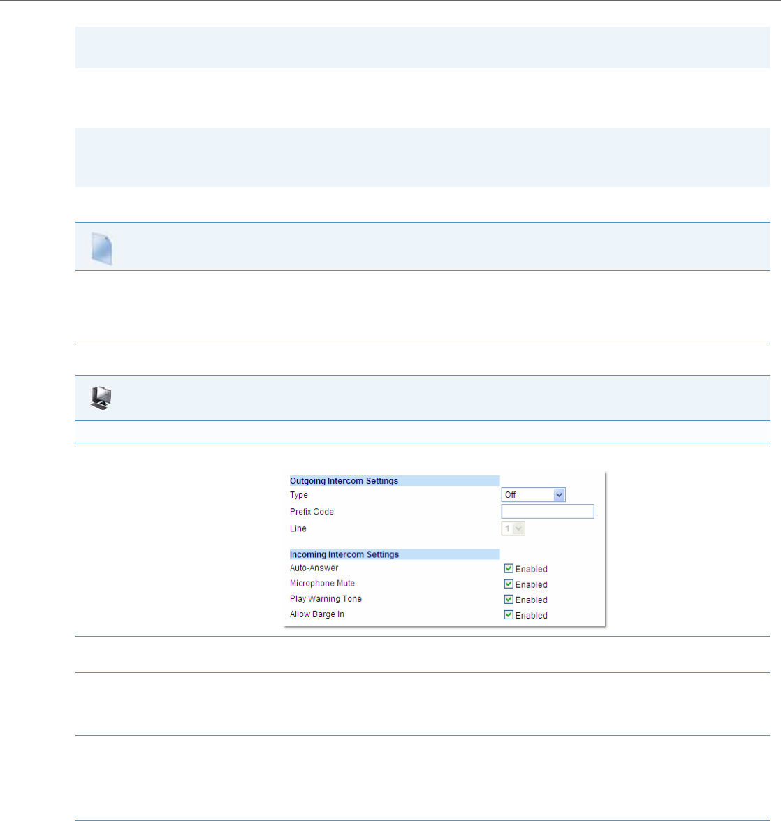
Operational Features
41-001343-02 REV04 – 05.2014 5-81
Configuring Intercom Calls Settings
You can configure the Intercom feature using the configuration files or the Aastra Web UI.
Use the following procedures to configure Intercom calls on the IP phone.
Note:
To configure incoming intercom calls using these parameters, see “Configuring Intercom Calls Settings” on page5-81.
Note:
An administrator can configure the incoming and outgoing Intercom feature. A user can configure the incoming Inter-
com feature only.
Configuration Files
For specific parameters you can set in the configuration files for outgoing Intercom, see Appendix A, the section, “Outgoing Intercom Settings” on
pageA-144.
For specific parameters you can set in the configuration files for incoming Intercom, see Appendix A, the section, “Incoming Intercom Settings” on
pageA-145.
Aastra Web UI
Outgoing intercom Settings
1. Click on Basic Settings->Preferences->Outgoing Intercom Settings.
2. Select an Intercom type for outgoing Intercom calls from the Type list box.
Valid values are Phone-Side, Server-Side, Off. Default is Off.
3. If Server-Side is selected, enter a prefix to add to the phone number in the "Prefix Code" field.
Note:
For Sylantro servers, enter *96.
4. If Phone-Side or Server-Side is selected, select a line from the Line list box for which you want the IP phone to use as its configuration on the
Intercom call.
Note:
The IP phone uses the configuration from the line you select from this list box. The call itself is made using the first available line at the time
of the call.
5. Click Save Settings to save your changes.
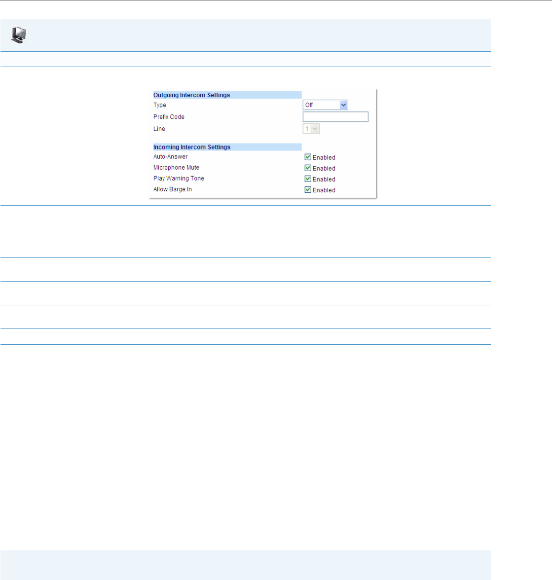
Operational Features
5-82 41-001343-02 REV04 – 05.2014
Group Paging RTP Settings
An Administrator or User can configure a specific key (softkey, programmable key, or expansion module key) on the
phone that allows you to send/receive a Real Time Transport Protocol (RTP) stream to/from pre-configured multicast
addresses without involving SIP signaling. This is called Group Paging on the IP phones. You can specify up to 5 listening
multicast addresses.
An Administrator can use the following parameters in the configuration files to set Group Paging RTP Settings:
•paging group listening
•softkeyN type, topsoftkeyN type, prgkeyN type, or expmodX keyN type
•sofkeyN label
•softkeyN value, topsoftkeyN value, prgkeyN value, or expmodX keyN value
An Administrator or User can use the following parameters in the Aastra Web UI to set Group Paging RTP Settings:
•Paging Listen Addresses (Path: Basic Settings->Preferences->Group Paging RTP Settings)
•<Paging> Key (Operation->Softkeys and XML, Programmable Keys, or Expansion Module Keys)
Incoming intercom Settings:
1. Click on Basic Settings->Preferences->Incoming Intercom Settings.
2. The "Auto-Answer" field is enabled by default. The automatic answering feature is turned on for the IP phone for answering Intercom calls.
To disable this field, uncheck the box.
Note:
If the Auto-Answer field is not checked (disabled), the phone treats the incoming intercom call as a normal call.
3. The "Microphone Mute" field is enabled by default. The microphone is muted on the IP phone for Intercom calls made by the originating
caller. To disable this field, uncheck the box.
4. The "Play Warning Tone" field is enabled by default. If “Auto-Answer” is enabled, the phone plays a warning tone when it receives in incom-
ing intercom call. To disable this field, uncheck the box.
5. The "Allow Barge In" field is enabled by default. If an active line on the phone receives an incoming intercom call, the active call is put on
hold and the phone automatically answers the incoming intercom call. To disable this field, uncheck the box.
6. Click Save Settings to save your changes.
Note:
The Group Paging RTP Settings are dependant upon the setting for the “Allow Barge In” parameter.
Aastra Web UI
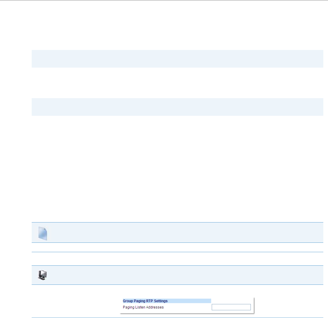
Operational Features
41-001343-02 REV04 – 05.2014 5-83
How it works
After pressing a configured “Paging” key on the phone, the phone sends an RTP stream to a preconfigured multicast
address (IP port). Any phone in the local network then listens for the RTP stream on the preconfigured multicast address
(IP port). For both sending and receiving of the multicast RTP there is no sip signaling involved. When the phone sends or
receives a multicast RTP, it shows its involvement to the user by displaying "Paging".
The phone uses a preconfigured G711 uLaw CODEC for multicast RTP.
For Paging Systems, the phone only plays RTP traffic; users have the ability to drop a rogue page. The recipient can drop
the incoming page if required. The recipient can also set Do Not Disturb (DND) to ignore any incoming pages.
For incoming RTP multicasts, the ringing display is dependant on the “Allow Barge-In” parameter. If this parameter is dis-
abled, and there is not other call on the phone, then the paging is automatically played via the preferred audio device (see
the <Model-Specific> IP Phone User Guide for setting Audio Mode on the phone).
If there is an existing call on the phone, the call initially displays in the ringing state. The user has the option to
accept/ignore the call. If the “Allow Barge-In” parameter is enabled, the RTP multicast call barges in, and any existing calls
are put on hold.
If an RTP multicast session already exists on the phone, and the phone receives another incoming RTP multicast session,
the priority is given to the first multicast session and the second multicast session is ignored. The behavior for the incom-
ing calls in this case is also based on the setting for the “Allow Barge-in” parameter. The incoming call is handled as if
there were an existing call already on the phone.
Configuring Group Paging RTP Settings
Use the following procedure to configure Group Paging RTP Settings using the configuration files.
Use the following procedure to configure RTP streaming for Paging applications using the Aastra Web UI.
Note:
Multicast RTP is one way only - from sender to the receiver (i.e. from sender to the multicast address (receiver)).
Note:
For outgoing RTP multicasts, all other existing calls on the phone are put on hold.
Configuration Files
For specific parameters you can set in the configuration files, see Appendix A, the section, “Group Paging RTP Settings” on pageA-147.
Aastra Web UI
1. Click on Basic Settings->Preferences->Group Paging RTP Settings.
2. In the “Paging Listen Addresses” text box, enter the multicast IP address(es) and port number(s) on which the phone listens for incoming
multicast RTP packets.
Notes:
•Enter the IP address in dotted decimal format (for example, 224.0.0.2:10000,239.0.1.20:15000) If this field is blank, Paging listening
capability is disabled on the phone.
•The valid port range is from 1 to 65535.
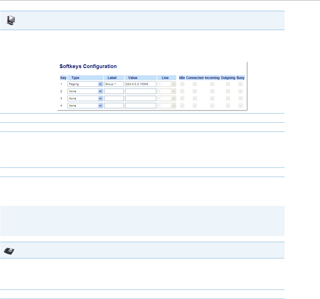
Operational Features
5-84 41-001343-02 REV04 – 05.2014
Using the Configured Paging Key on the IP Phone
The following procedure describes the use of the Paging key. The procedures assumes you have already configured the
Paging key using the configuration files or the Aastra Web UI.
Speeddial Key Mapping
There are hard keys on your phone, such as Hold, Redial, Xfer, and Conf that are configured by default for specific call-
handling features. (See the <Model-Specific> IP Phone User Guide for more information about these key functions).
3. Click on Softkeys and XML.
or
Click on Programmable Keys.
or
Click on Expansion Module Keys.
4. Choose a key that you want to assign as the Paging Key and select Paging from the “Type” field.
5. In the “Label” field, enter a key label to assign to the Paging key (for example, “Group 1”).
6. In the “Value” field, enter a multicast IP address and a port number for the Paging key. When you press this key, the phone initiates an out-
going multicast RTP session to the specified address using the specified port. (For example, 224.0.0.2:10000).
Notes:
•When you select Paging for the “Type” field, the “Line” field and state fields are disabled.
•The valid port range is from 1 to 65535.
7. Click Save Settings to save your changes.
Notes:
•The recipient of a Paging call can set a global “Do Not Disturb” (DND) to ignore any incoming pages.
•For incoming Paging, the phones use the Intercom configuration settings. The incoming Page is dependant on the
“Allow Barge-In” parameter setting and the “Idling/On Call” state.
IP Phone UI
1. On the IP Phone, press the key you configured for Paging.
The phone opens a multicast RTP session and an outgoing OR incoming phone screen displays.
Note:
If you enable global DND on the phone, the incoming multicast RTP session is dropped.
2. Press the Drop key to end the multicast RTP session and return to the idle screen.
Aastra Web UI
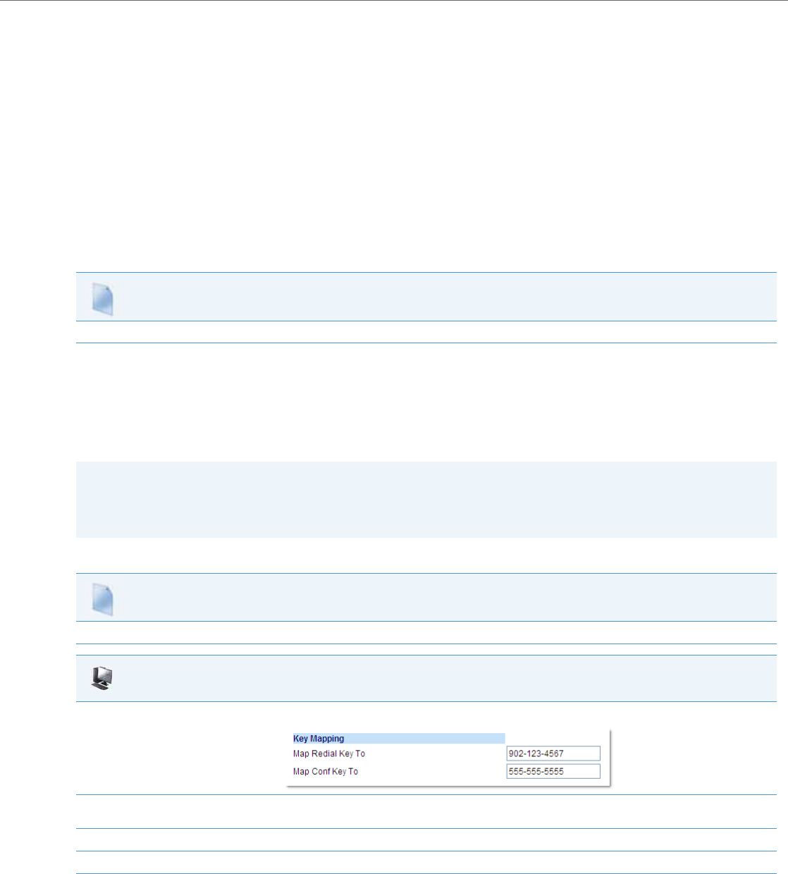
Operational Features
41-001343-02 REV04 – 05.2014 5-85
Enabling/Disabling Redial, Xfer, and Conf Keys
You can enable or disable the Redial, Xfer, and Conf keys as required using the following parameters in the configuration
files:
•redial disabled
•conference disabled
•call transfer disabled
Valid values for this parameter are 0 (enabled) and 1 (disabled).
If this parameter is set to 1, the key is not active and is ignored if pressed by the user. For "redial disabled" the value of 1
does not save the dialed number to the "Redial List".
If this parameter is set to 0, the key is active and can be pressed by the user.
This feature is configurable via the configuration files only.
Use the following procedure to enable/disable the Redial, Xfer, and Conf keys.
Mapping Redial and Conf Keys as Speeddials
You can map the Redial and Conference keys on the IP phone to use as Speeddial keys. When the Redial or Conference
key is pressed, the number configured for the key automatically speeddials. If no number is configured, the Redial and
Conference keys return to their original functionality.
You can configure this feature using the configuration files or the Aastra Web UI.
Use the following procedures to set the Redial and Conf keys as Speeddial keys.
Configuration Files
For specific parameters you can set in the configuration files, see Appendix A, the section, “Mapping Key Settings” on pageA-152.
Note:
If you configure the Redial and Conference keys for speeddialing on the 6757i CT Base Station, the Redial and Con-
ference keys on the 6757i CT handset retain their original functionality. The Redial and Conference keys on the hand-
set are not configured for speeddial.
Configuration Files
For specific parameters you can set in the configuration files, see Appendix A, the section, “Mapping Key Settings” on pageA-152.
Aastra Web UI
1. Click on Basic Settings->Preferences.
2. In the Key Mapping section, enter a number in the "Map Redial Key To" field, that the IP phone will use to speeddial when the Redial key
is pressed.
3. Enter a number in the "Map Conf Key To" field, that the IP phone will use to speeddial when the Conf Key is pressed.
4. Click Save Settings to save your changes.

Operational Features
5-86 41-001343-02 REV04 – 05.2014
Using Redial Key for “Last Number Redial”
The IP phones have an enhanced redial user interface that allows a user to quickly redial the last number that was dialed
out from the phone. You can:
•Press the Redial key twice to redial the last number dialed.
•Press the Redial key once, scroll the list of numbers, then press the Redial button again to dial the number that dis-
plays on the screen.
The “last number redial” feature for the Redial key is static and is not configurable.
Send DTMF for Remapping Conference or Redial Key
Previously, the “Conf” and “Redial” keys could be mapped to a speed dial to generate a call to a custom number when
the phone was idle. During an active call, pressing the “Redial” or “Conf” keys would put the current call on hold and
then dial the custom number. Now the “Conf” and “Redial” key remappings have the same behavior as the “Speed Dial”
key when the phone is idle. During an active call the phone will send the custom number as DTMF using the phone con-
figured DTMF method (inbound vs out-of-band RFC2833 vs SIP INFO).
This feature can be configured using the new “map redial as dtmf” and “map conf as dtmf” parameters.
When a user presses the “Redial” key, the mapped number will be sent out as DTMF during an active call if the current
“map redial key to” parameter is configured to a number and the “map redial as dtmf” parameter is set to “1”.
When a user presses the “Conf” key, the mapped number will be sent out as DTMF during an active call if the current
“map conf key to” parameter is configured to a number and “map conf as dtmf” parameter is set to “1”.
Enabling or Disabling the Sending of DTMF with Remapped Redial and Conf Keys
Use the following procedures to configure the remapping of the “Redial” and “Conf” keys on the IP phone.
Note:
You can use the Redial key during active calls.
Configuration Files
For specific parameters you can set in the configuration files, see Appendix A, the section, “Send DTMF for Remapping Conference or Redial Key” on
pageA-153.

Operational Features
41-001343-02 REV04 – 05.2014 5-87
Ring Tones and Tone Sets
You can configure ring tones and ring tone sets on the IP phones.
Ring Tones
There are several distinct ring tones a user or administrator can select from to set on the IP phones. You can enable/disable
these ring tones on a global basis or on a per-line basis.
The following table identifies the valid settings and default values for each type of configuration method.
Ring Tone Settings Table
Configuration Method Valid Values Default Value
Configuration Files Global:
0 (Tone1)
1 (Tone 2)
2 (Tone 3)
3 (Tone 4)
4 (Tone 5)
5 (Silent)
Per-Line:
-1 (global)
0 (Tone1)
1 (Tone 2)
2 (Tone 3)
3 (Tone 4)
4 (Tone 5)
5 (Silent)
Global:
0 (tone 1)
Per-Line:
-1 (global)
IP Phone UI Global:
Tone 1
Tone 2
Tone 3
Tone 4
Tone 5
Global:
Tone 1
Configuration Method Valid Values Default Value
Aastra Web UI Global:
Tone 1
Tone 2
Tone 3
Tone 4
Tone 5
Silent
Per-Line:
Global
Tone 1
Tone 2
Tone 3
Tone 4
Tone 5
Silent
Global:
Tone 1
Per-Line:
Global

Operational Features
5-88 41-001343-02 REV04 – 05.2014
Ring Tone Sets
In addition to ring tones, you can configure ring tone sets on a global-basis on the IP phones. Ring tone sets consist of
tones customized for a specific country. The ring tone sets you can configure on the IP phones are:
•Australia
•Brazil
•Europe (generic tones)
•France
•Germany
•Italy
•Italy2
•Malaysia
•Mexico
•Russia
•Slovakia
•UK
•US (Default - also used in Canada)
When you configure the country's tone set, the country-specific tone is heard on the phone for the following:
•dial tone
•secondary dial tone
•ring tone
•busy tone
•congestion tones
•call waiting tone
•ring cadence pattern
Configuring Ring Tones and Tone Sets
Use the following procedures to configure ring tones and tone sets on the IP phones.
Note:
You configure ring tones and tone sets using the Aastra Web UI, IP Phone UI, or configuration files. However, when
using the IP phone UI, you can set global configuration only.
Configuration Files
For specific parameters you can set in the configuration files for ring tones, see Appendix A, the section, “Ring Tone and Tone Set Global Settings” on
pageA-120 or “Ring Tone Per-Line Settings” on pageA-121.
IP Phone UI
For global configuration only:
1. Press on the phone to enter the Options List.
2. Select Preferences.
3. Select Tones.
4. Select Set Ring Tone.
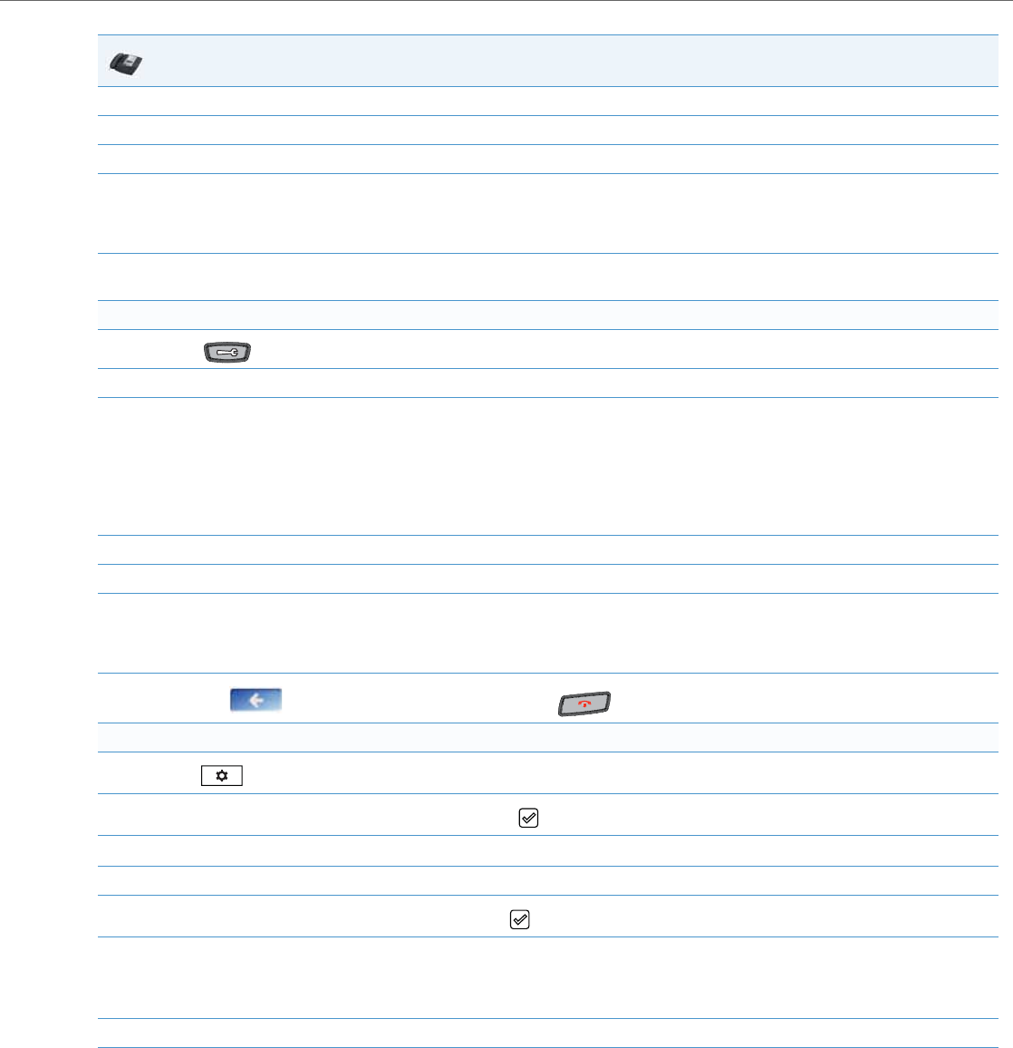
Operational Features
41-001343-02 REV04 – 05.2014 5-89
5. Select the type of ring tone (Tone 1 through Tone 5, or Silent).
6. Press Done to save the change.
7. Select Tone Set.
8. Select the country for which you want to apply the tone set.
Valid values are Australia, Brazil, Europe, France, Germany, Italy, Italy2, Malaysia, Mexico, Brazil, Russia, Slovakia, UK, and US. Default
is US.
9. Press Done to save the change.
The ring tone and tone set you select is immediately applied to the IP phone.
For the 6739i:
1. Press on the phone to enter the Options List.
2. Press the <Audio> button.
3. Press the <Ring Tone> button. The following values display:
•Tone 1 (Default)
•Tone 2
•Tone 3
•Tone 4
•Tone 5
•Silent
4. Press the value you want to set for the Ring Tone.
5. Press the <Tone Set> button.
6. Select the country for which you want to apply the Tone Set.
Valid values are Australia, Brazil, Europe, France, Germany, Italy, Italy2, Malaysia, Mexico, Brazil, Russia, Slovakia, UK, and US. Default
is US
7. Press the to return to the previous menu or press the to return to the idle screen.
For the 6867i:
1. Press to enter the Options List.
2. Navigate to the Audio > Ring Tones option and press the button or Select softkey.
3. Use the 5 and 2 keys to scroll through and choose the desired ring tone (Tone 1 through Tone 5, or Silent).
4. Press the Save softkey to save your changes.
5. Navigate to the Audio > Tone Sets option and press the button or Select softkey.
6. Use the 5 and 2 keys to scroll through and choose the desired tone set.
Valid values are Australia, Brazil, Europe, France, Germany, Italy, Italy2, Malaysia, Mexico, Brazil, Russia, Slovakia, UK, and US. Default
is US.
7. Press the Save softkey to save your changes.
IP Phone UI
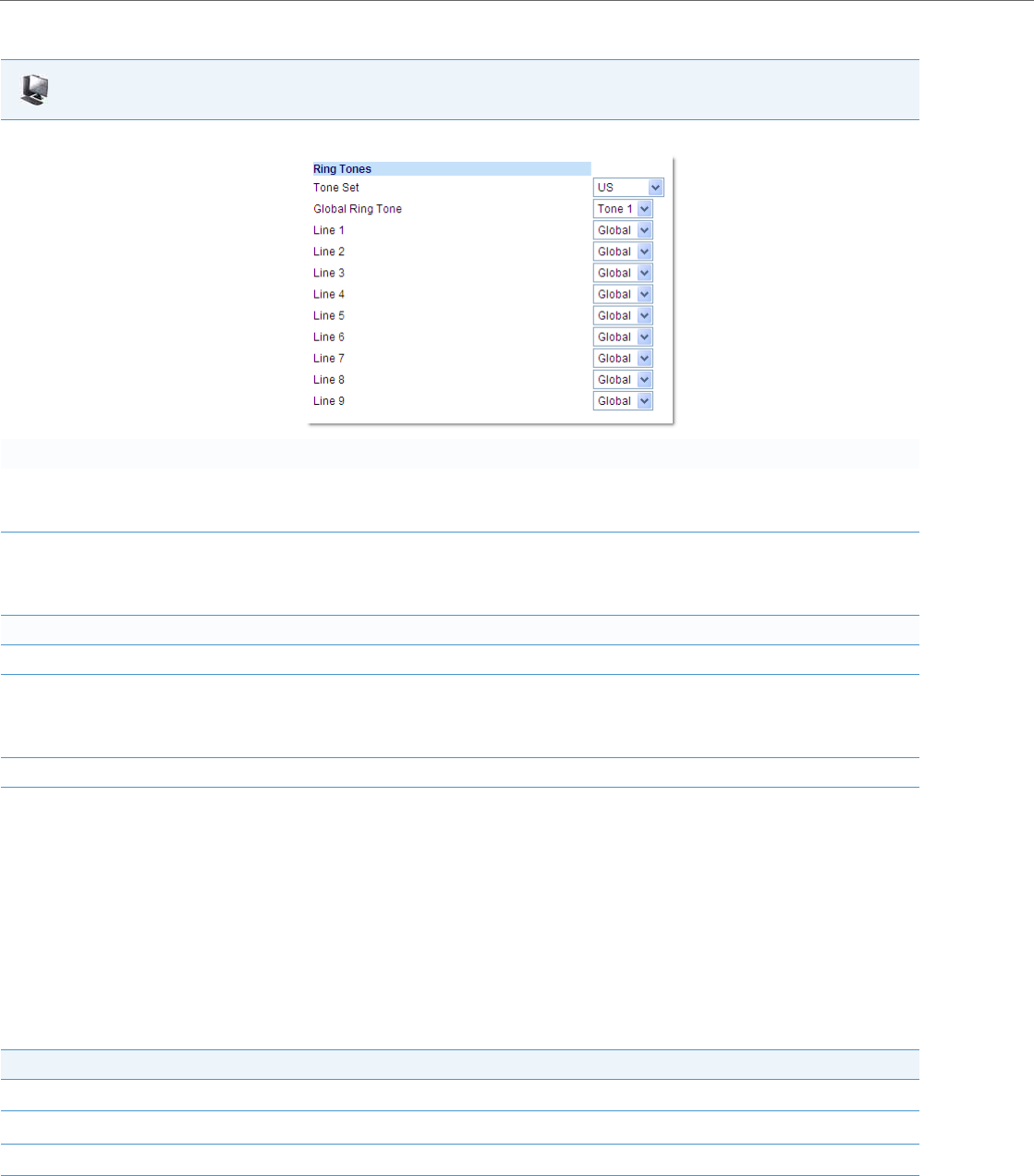
Operational Features
5-90 41-001343-02 REV04 – 05.2014
Ring Tone via Speaker During Active Calls
The parameter “ring audibly enable” can be used to configure the IP phones to play the ring tone of an incoming call
via the phone’s speaker while in an active call or if a user is in the process of dialing out.
With the parameter enabled, if a user is in an active call on an extension, and the phone receives a call for the same or dif-
ferent extension, the incoming call will be represented by the call’s ring tone being played through the speaker as well as
the respective line’s LED flashing. This is also the case if a user is in the process of dialing out to a remote number and the
phone receives a call for any line other than the line that is being used to dial out. When the phone exits the ringing state
(e.g. the incoming call is answered), the tone device of the phone will revert back to originally configured audio device.
Feature compatibility is dependant on the IP phone model (see the following table for compability details).
Aastra Web UI
1. Click on Basic Settings->Preferences.
For global configuration:
2. In the "Ring Tones" section, select a country from the "Tone Set" field.
Valid values are Australia, Brazil, Europe, France, Germany, Italy, Italy2, Malaysia, Mexico, Brazil, Russia, Slovakia, UK, and US. Default
is US
3. Select a value from the "Global Ring Tone" field.
Note:
See the “Ring Tone Settings Table” on page5-87 for valid values.
For per-line configuration:
4. In the "Ring Tone" section, select a line for which you want to set ring tone.
5. Select a value from the "LineN" field.
Note:
See the “Ring Tone Settings Table” on page5-87 for valid values.
6. Click Save Settings to save your changes.
IP Phone Handset Audio Mode Speaker Audio Mode
9143i XX
9480i and 9480i CT X
6730i XX
6731i XX

Operational Features
41-001343-02 REV04 – 05.2014 5-91
Configuring the Ring Tone via Speaker During Active Calls Feature
Use the following procedures to configure the ring tone via speaker during active calls feature.
No Service Congestion Tone
Administrators can configure the IP phones to play a congestion/fast busy tone instead of a dial tone when the phone is in
a “No Service” state. This feature allows visually impaired persons the ability to discern whether or not the phone is in serv-
ice and can be used to send/receive calls.
The configuration parameter “no service congestion tone” allows administrators the ability to enable this accessibility
feature. When enabled, the congestion tone will replace the conventional dial tone when the handset is off hook, a head-
set is employed, or the speakerphone is engaged. The congestion tone’s frequency/pattern is based on the respective
phone’s configured tone set. Additionally, the congestion tone is played on a per-line basis whereby only the specific lines
that are without service are affected.
With consideration to scenarios where a dial tone should be played even if the phone is in a “No Service” state (e.g. scenar-
ios where the proxy may still accept INVITEs from the phone even if unregistered), the “no service congestion tone”
parameter has been programmed as disabled by default.
6735i
6737i
6739i X
6753i X
6755i X
6757i and 6757i CT X
6863i
6865i
6867i
Notes:
•The “ring audibly enable” parameter is disabled by default.
•This feature is not supported when utilizing the headset audio mode.
•With this feature enabled and when the phone’s speaker is playing the incoming call’s ring tone, call-waiting tones
will not be played.
Configuration Files
For specific parameters you can set in the configuration files, see Appendix A, the section, “Ring Tone via Speaker During Active Calls Settings” on
pageA-121.
Note:
If the phone or individual lines are configured to have no registration by intent (e.g. if the Registrar is set to 0.0.0.0) ena-
bling the “no service congestion tone” parameter will have no effect and the default dial tone will be played.
IP Phone Handset Audio Mode Speaker Audio Mode

Operational Features
5-92 41-001343-02 REV04 – 05.2014
Configuring the No Service Congestion Tone
Use the following procedures to configure the no service congestion tone feature.
Priority Alerting
Priority alerting on the IP phones is a feature that allows incoming calls to trigger pre-defined ringing or call waiting alert
tones.
You can enable or disable priority alerting on the IP phone for the Asterisk, Broadworks, and Sylantro servers using the
configuration files and the Aastra Web UI. Configuration of priority alerting is on a global-basis only.
How Priority Alerting Works
When the IP phone detects an incoming call, the phone firmware inspects the INVITE request in the IP packet for an
"Alert-Info" header.
If it contains an "Alert-Info" header, the firmware strips out the URL and keyword parameter and maps it to the appropri-
ate Bellcore tone.
If there is no keyword parameter in the "Alert-Info" header, or the INVITE message contains no "Alert-Info" header, then
the IP phone firmware uses the Bellcore standard ring tone.
Asterisk/Broadworks Servers
The ring tone keywords that can display in the "Alert-Info" header for an Asterisk and Broadworks server are:
•Bellcore-dr2
•Bellcore-dr3
•Bellcore-dr4
•Bellcore-dr5
When the ring tone keywords appear in an "Alert-Info" header from an Asterisk or Broadworks server, the IP phone maps
the keywords to the default ring tone patterns.
Example:
The following are examples of the Asterisk/Broadworks Server ring tone keywords:
Alert-Info: <http://127.0.0.1/Bellcore-dr2>
or
Alert-Info: <Bellcore-dr2>
Configuration Files
For specific parameters you can set in the configuration files, see Appendix A, the section, “No Service Congestion Tone Settings” on pageA-122.

Operational Features
41-001343-02 REV04 – 05.2014 5-93
Sylantro Servers
The ring tone keywords that can display in the "Alert-Info" header for a Sylantro server are:
•alert-acd (auto call distribution)
•alert-community-1
•alert-community-2
•alert-community-3
•alert-community-4
•alert-emergency
•alert-external
•alert-group
•alert-internal
•alert-priority
When the ring tone keywords appear in an "Alert-Info" header from a Sylantro server, the keyword is mapped to the ring
tone pattern based on the configuration you set in the Aastra Web UI or the configuration files.
Ring Tone Patterns
In IP Telephony, different ringing patterns have different frequencies and cadences. Ring cadence is the ringing pattern
heard by the called party, before they pick up the call.
On the IP phones, if you enable priority alerting when using an Asterisk or Broadworks server, the IP phone uses the fol-
lowing Bellcore-specified tones by default:
Ring Tone Pattern (Asterisk/Broadworks Servers)
If you enable priority alerting when using a Sylantro server, you can specify the Bellcore tone to be used for the following
configurable criteria:
Ring Tone Pattern (Sylantro Servers)
Call Criteria Bellcore Tones
internal calls Bellcore-dr2
external calls Bellcore-dr3
calls with contact list Bellcore-dr4
calls with specific time frames Bellcore-dr5
Call criteria Bellcore tones for each call criteria
alert-acd (auto call distribution)
alert-community-1
alert-community-2
alert-community-3
alert-community-4
alert-emergency
alert-external
alert-group
alert-internal
alert-priority
Normal ringing (default)
Bellcore-dr2
Bellcore-dr3
Bellcore-dr4
Bellcore-dr5
Silent

Operational Features
5-94 41-001343-02 REV04 – 05.2014
A System Administrator can configure the ring tone cadences if required, using the configuration files. The following
table identifies the different Bellcore ring tone patterns and cadences.
Mexican Tone Set Cadences
The following are Mexican tone set cadences.
Bellcore Tone Pattern ID Pattern Cadence Minimum Duration (ms) Nominal Duration (ms) Maximum Duration (ms)
(Standard) 1 Ringing
Silent
2s On
4s Off
1800
3600
2000
4000
2200
4400
Bellcore-dr2 2 Ringing
Silent
Ringing
Silent
Long
Long
Long
630
315
630
3475
800
400
800
4000
1025
525
1025
4400
Bellcore-dr3 3 Ringing
Silent
Ringing
Silent
Ringing
Silent
Short
Short
Long
315
145
315
145
630
2975
400
200
400
200
800
4000
525
525
525
525
1025
4400
Bellcore-dr4 4 Ringing
Silent
Ringing
Silent
Ringing
Silent
Short
Long
Short
200
145
800
145
200
2975
300
200
1000
200
300
4000
525
525
1100
525
525
4400
Bellcore-dr5 5 Ringing 450 500 550
Note:
If the "Do Not Disturb" (DND) or the "Call Forward" (CFWD) feature is enabled on the server-side, and the user is still
waiting for a call, the "Bellcore-dr5" is a ring splash tone that reminds the user that these are enabled.
Tone Frequency (Hz) Cadence (on/off)
Dial 425 Continuous
Secondary Dial 425 300/100/300/1300
Ringing 425 1000/4000
Busy 425 500/500
Congestion 425 250/250
Call Waiting 425 100/100/100/10000
Ring Cadence 1000/4000

Operational Features
41-001343-02 REV04 – 05.2014 5-95
Brazilian Tone Set Cadences
The following are Brazilian tone set cadences.
Russian Tone Set Cadences
The following are Russian tone set cadences.
Malaysian Tone Set Cadences
The following are Malaysian tone set cadences.
Limitations for Malaysian Cadences
•The phone does not apply a different volume level to the first part of the call waiting tone.
•The level of the 50Hz modulation signal for ring back is 90%.
Tone Frequency (Hz) Cadence (on/off)
Dial 425 Continuous
Secondary Dial 425 300/100/300/1300
Ringing 425 1000/4000
Busy 425 250/250
Congestion 425 500/500
Call Waiting 425 100/100/100/10000
Ring Cadence 1000/4000
Tone Frequency (Hz, dBm0) Cadence (ms) tone pause tone Note
Dial 425, -10 - Continuous
Special Dial 425, -10 500/50 Repetitive
Busy 425, -10 500/500 Repetitive
Ringing 425, -10 1000/4000 Repetitive
Congestion 425, -10 200/200 Repetitive
Call Waiting 425, -10 200/600/200 Non-repetitive
Tone Frequency (Hz) Cadence (on/off)
Dial 425 Continuous
Secondary Dial 425 160/160
Ringing 425 * 50 400/200/400/2000
Busy 425 500/500
Congestion 425 250/250
Call Waiting 425 100/200/100/8600
Ring Cadence - 400/200/400/2000

Operational Features
5-96 41-001343-02 REV04 – 05.2014
Italian Tone Set Cadences
The following are Italian tone set cadences (for “Italy”).
Slovak Tone Set Cadences
The following are Slovak tone set cadences.
Configuring Priority Alerting and Ring Tone Cadences using the Configuration Files
Use the following procedures to configure priority alerting and ring tone cadences on the IP phones.
Tone Frequency (Hz) Cadence (on/off)
Dial 425 0.2/0.2/0.6/1.0
Secondary Dial 425 Continuous
Ringing 425 1.0/4.0
Busy 425 0.5/0.5
Congestion 425 0.2/0.2
Call Waiting 425 0.40/0.10/0.25/0.10/0.15
Tone Frequency (Hz) Cadence (on/off)
Dial 425 0.33/0.33/0.66/0.66
Secondary Dial 425 (0.165/0.165)x3 /0.66/0.66
Ringing 425 1.0/4.0
Busy 425 0.33/0.33
Congestion 425 0.165/0.165
Call Waiting 425 0.33 on repeating every 10 sec when Call Waiting
period is set to 10
Configuration Files
For specific parameters you can set in the configuration files, see Appendix A, the sections,
•“Priority Alert Settings” on pageA-127.
•“Bellcore Cadence Settings” on pageA-131.
Note:
You can configure Bellcore cadences using the configuration files only.
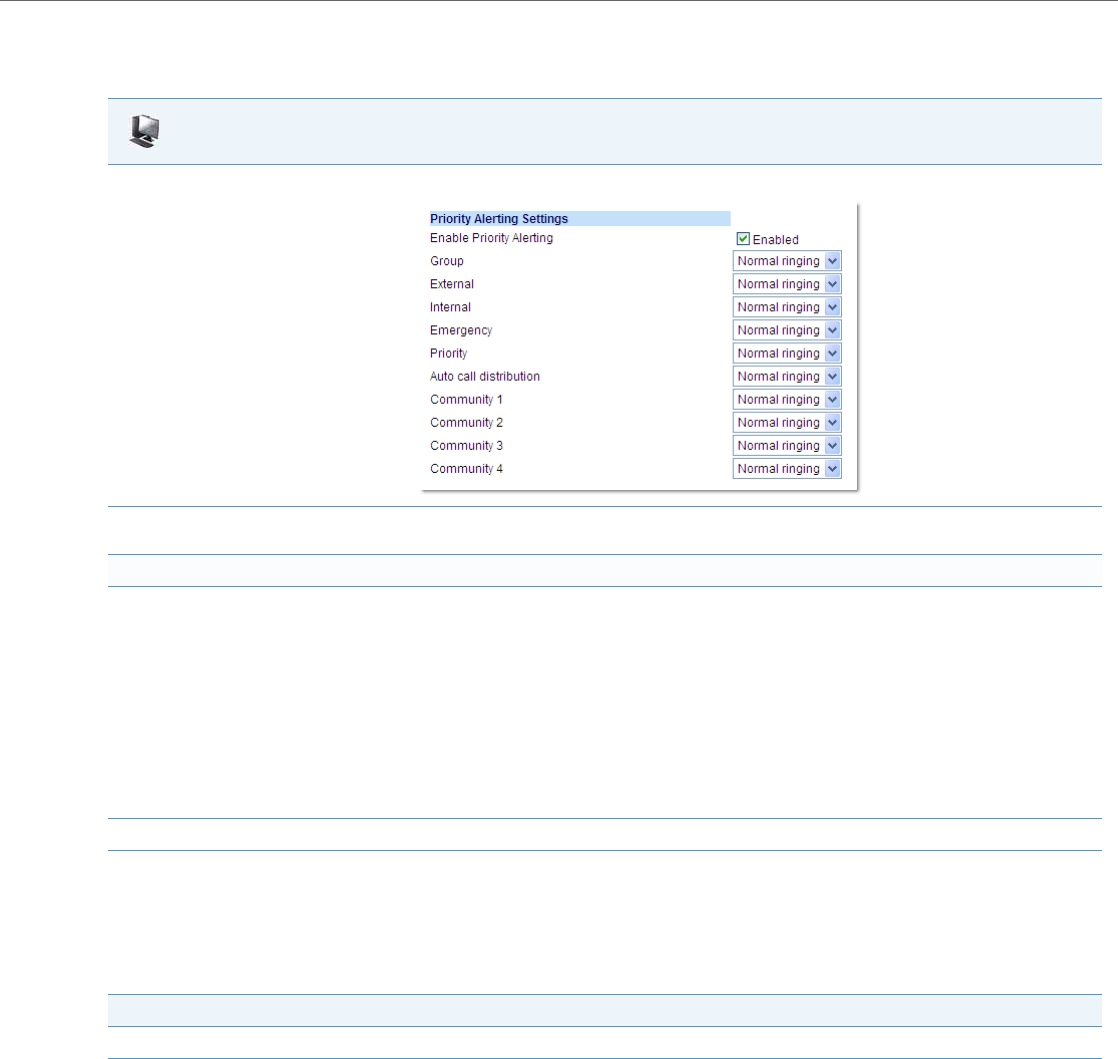
Operational Features
41-001343-02 REV04 – 05.2014 5-97
Configuring Priority Alerting using the Aastra Web UI
Use the following procedure to configure Priority Alerting using the Aastra Web UI.
Call Waiting Tones
Call Waiting is a feature that tells you if a new caller is trying to contact you when you are already on the phone. A discreet
tone alerts you to the new caller, so you can answer your second incoming call by putting your first caller on hold.
The IP phones use the following Bellcore-specified call waiting tones.
Aastra Web UI
1. Click on Basic Settings->Preferences.
2. In the "Priority Alerting Settings" section, enable the "Enable Priority Alerting" field by checking the check box. (Disable this field by
unchecking the box).
For Sylantro Servers:
3. Select a ring tone pattern for each of the following fields:
•Group
•External
•Internal
•Emergency
•Priority
•Auto call distribution
•Community 1
•Community 2
•Community 3
•Community 4
4. Click Save Settings to save your changes.
Bellcore Call-Waiting Tone Pattern ID Pattern Minimum Duration (ms) Nominal Duration (ms) Maximum Duration (ms)
CallWaitingTone 1 1 Tone On 270 300 330
Bellcore-dr2 CallWaitingTone2 2 Tone On
Tone Off
90
90
100
100
110
110

Operational Features
5-98 41-001343-02 REV04 – 05.2014
For Asterisk and Broadworks servers, call waiting tones are specified by the default Bellcore tones indicated in the table
Ring Tone Pattern (Asterisk/Broadworks Servers) on page 5-93.
For Sylantro servers, call waiting tones are specified by the Bellcore tones you configure in the Aastra Web UI or the con-
figuration files. See the table Ring Tone Pattern (Sylantro Servers) on page 5-93.
Reference
For more information about enable/disabling call waiting on the IP Phone, see the section, “Call Waiting” on page5-57.
Directed Call Pickup (BLF or XML Call Interception)
Directed call pickup (for Asterisk and sipXecs servers) is a feature on the phones that allows a user to intercept a call on a
ringing phone which is part of the same interception group. The phones also support the Busy Lamp Field (BLF) hold
state that is expressed by a slow flashing LED. When using an Asterisk server, if administrators configure BLF for Directed
Call Pickup, users are able to pickup the held call, as the phone sends the directed call pickup prefix to the extension
number.
You can use the Directed call pickup feature on the phone in multiple ways:
•With the existing BLF feature on Asterisk or sipXecs, a user can dial “*76” or “*78” respectively, followed by the exten-
sion to pick up a ringing call on another phone. (For more information about BLF, see “Busy Lamp Field (BLF)” on
page 5-128.
•Using XML, a user can intercept a call by selecting an extension from a list and then pressing a “Pickup” softkey/pro-
grammable key. To use the Directed call pickup feature from an XML application, you must list all ringing extensions
using the AastraIPPhoneTextMenu XML object in an XML script. This allows the user to select the ringing extension
from a text menu without having to dial.
BLF and XML softkeys/programmable keys monitor the states of an extension. The extension states can be one of three
states: "busy", "ringing" and "idle". If the monitored extension is in the "ringing" state with an incoming call, and "Directed
call pickup" is enabled, pressing the BLF or XML key can pick up the incoming call on the monitored extension.
Reference
For more information about using the AastraIPPhoneTextMenu object, contact Aastra Customer Support regarding the
Aastra XML Development Guide.
Directed Call Pickup Prefix (optional)
The optional “directed call pickup prefix” allows you to enter a specific prefix string (depending on what is available on
your server), that the phone automatically dials when dialing the Directed Call Pickup number. For example, for Broad-
soft servers, you can enter a value of *98 for the “directed call pickup prefix” (for sipXecs, *78 is used). When the phone
performs the Directed Call Pickup after pressing a BLF or BLF/List softkey, the phone prepends the *98 value to the desig-
nated extension of the BLF or BLF/List softkey when dialing out.
Bellcore-dr3 CallWaitingTone3 3 Tone On
Tone Off
Tone On
Tone Off
90
90
90
90
100
100
100
100
110
110
110
110
Bellcore-dr4 CallWaitingTone4 4 Tone On
Tone Off
Tone On
Tone Off
90
90
270
90
100
100
300
100
110
110
330
110
Note:
Feature availability is dependant on your call manager.
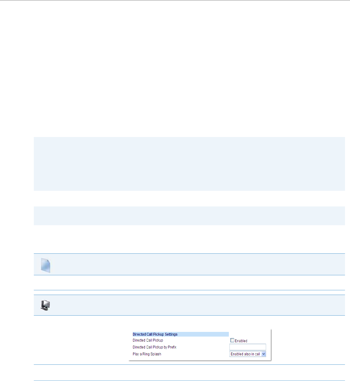
Operational Features
41-001343-02 REV04 – 05.2014 5-99
How this Feature Works when Directed Call Pickup is Enabled with BLF or BLF/List
How this Feature Works when Directed Call Pickup is Disabled with BLF or BLF/List
You can enable/disable “Directed Call Pickup” using the configuration files or the Aastra Web UI.
Enabling/Disabling Directed Call Pickup
Use the following procedure to enable or disable the Directed Call Pickup feature on the IP phone.
1. Phone A monitors Phone B via BLF/List.
2. Phone C calls Phone B; Phone B rings.
3. If you press the BLF/List softkey on Phone A, it picks up the ringing line on Phone B.
4. Phone C connects to Phone A.
1. Phone A monitors Phone B via BLF/List.
2. Phone C calls Phone B; Phone B rings
3. If you press the BLF/List softkey on Phone A, it performs a speeddial to Phone B.
4. Phone C and Phone A are ringing Phone B on separate lines (if available).
Notes:
•The default method for the phone to use is Directed Call Pickup over BLF if the server provides applicable informa-
tion. If the Directed Call Pickup over BLF information is missing in the messages to the server, the Directed Call Pickup
by Prefix method is used if a value for the prefix code exists in the configuration.
•You can define only one prefix, which will be applicable to all BLF- or BLF/List-monitored extensions.
•The phone that picks up displays the prefix code + the extension number (for example, *981234 where prefix key =
*98, extension = 1234).
Note:
The “Directed Call Pickup” feature is disabled by default.
Configuration Files
To enable/disable Directed Call Pickup on the IP phone using the configuration files, see Appendix A, the section, “Directed Call Pickup (BLF or XML Call
Interception) Settings” on pageA-150.
Aastra Web UI
1. Click on Basic Settings->Preferences->Directed Call Pickup Settings.
2. Enable the "Directed Call Pickup" field by checking the check box.
(Disable this field by unchecking the box). Default is disabled.)
3. (optional) Enter a prefix in the "Directed Call Pickup Prefix" field. For example, *98.
This prefix is appended to the beginning of the Directed Call Pickup number when dialed from the BLF or BLF/List softkey.
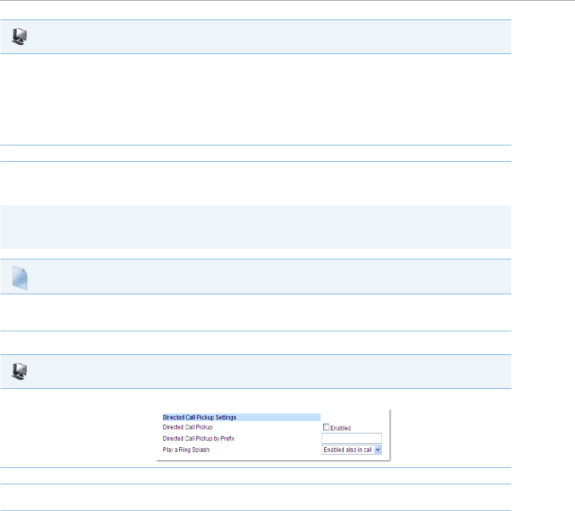
Operational Features
5-100 41-001343-02 REV04 – 05.2014
Configuring BLF/BLF List for Directed Call Pickup
Use the following procedure to configure BLF/BLF List for Directed Call Pickup in the configuration files.
Use the following procedure to configure BLF or BLF/List for Directed Call Pickup in the Aastra Web UI.
4. For the 6739i, 6755i, 6757i, and 6757i CT enable the "Play a Ring Splash" feature by selecting either Enabled (when idle) or Enabled also in
call (when idle and in an active call state. For all other IP phones enable the "Play a Ring Splash" feature by clicking on the checkbox.
(Default is disabled).
If the "Play a Ring Splash" parameter is enabled, the IP phone plays a short "ring splash" when there is an incoming call on the BLF moni-
tored extension.
Note:
This global setting is not dynamic. Changes to this setting will take effect only after the phone has been rebooted.
5. Click Save Settings to save your changes.
Note:
You must enable Directed Call Pickup before performing these procedures. See “Enabling/Disabling Directed Call
Pickup” on page5-99.
Configuration Files
To set BLF or BLF/List in the configuration files for Directed Call Pickup, see Appendix A, the sections:
•“Softkey/Programmable Key/Keypad Key/Feature Key/Expansion Module Key/Hard Key Parameters” on pageA-156.
•“BLF List URI Settings” on pageA-192.
Aastra Web UI
1. Click on Basic Settings->Preferences->Directed Call Pickup Settings.
2. Enable the "Directed Call Pickup" field by checking the check box.
3. (optional) Enter a prefix in the "Directed Call Pickup Prefix" field. For example, *98.
This prefix is appended to the beginning of the Directed Call Pickup number when dialed from the BLF or BLF/List softkey.
4. For the 6739i, 6755i, 6757i, and 6757i CT enable the "Play a Ring Splash" feature by selecting either Enabled (when idle) or Enabled also in
call (when idle and in an active call state. For all other IP phones enable the "Play a Ring Splash" feature by clicking on the checkbox.
(Default is disabled).
If the "Play a Ring Splash" parameter is enabled, the IP phone plays a short "ring splash" when there is an incoming call on the BLF moni-
tored extension.
Note:
This global setting is not dynamic. Changes to this setting will take effect only after the phone has been rebooted.
Aastra Web UI
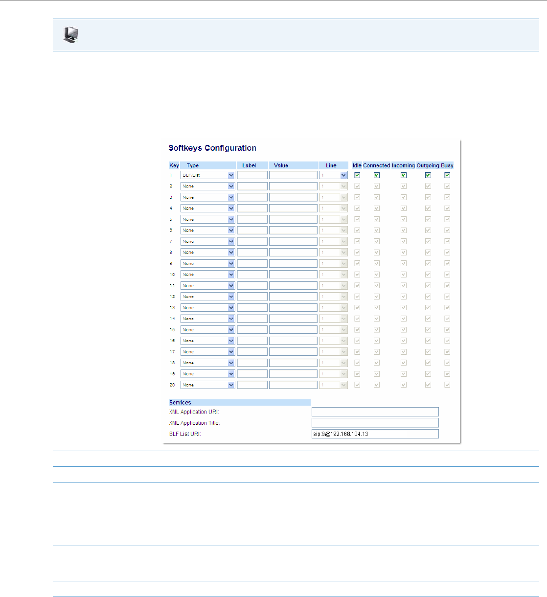
Operational Features
41-001343-02 REV04 – 05.2014 5-101
5. Click on Operation->Softkeys and XML
or
Click on Operation->Programmable Keys
or
Click on Operation->Expansion Module <N>.
Note:
Depending on your phone-model, the key configuration screen displays. The 6755i Key Screen is shown as an example.
6. Select a softkey or programmable key to configure.
7. In the "Type" field, select "BLF" (Asterisk), "BLF/List" (BroadSoft BroadWorks).
8. For 8 and 11-Line LCD softkeys:
In the "Label" field, enter the name of the person who’s extension you are monitoring (if “Type” is BLF).
Note:
If BLF/List type is selected, no label value is required. The BroadWorks BLF List name is configured in the "BLF List URI" field instead.
9. In the "Value" field, enter a value to associate with the softkey or programmable key.
For example, for BLF, the value is the extension you want to monitor.
For BLF/List, the value is an identifier for the list of numbers you are monitoring.
10. Click Save Settings to save your changes.
11. In the "Line" field, select a line number that is actively registered to the appropriate SIP proxy you are using.
Aastra Web UI
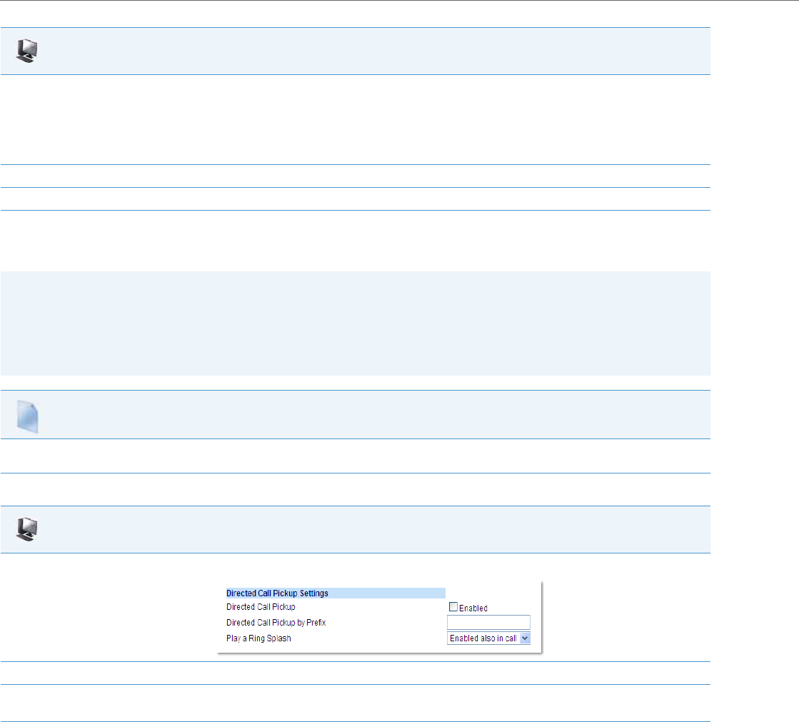
Operational Features
5-102 41-001343-02 REV04 – 05.2014
Configuring XML for Directed Call Pickup
Use the following procedure to configure XML for Directed Call Pickup in the configuration files.
Use the following procedure to configure XML for Directed Call Pickup in the Aastra Web UI.
12. In the "BLF List URI" field, enter the name of the BLF list defined on the BroadSoft BroadWorks Busy Lamp field page for your particular user.
For example, sip:9@192.168.104.13.
Note:
The value of the BLF/List URI parameter must match the list name configured. Otherwise, no values display on the 6757i screen and the fea-
ture is disabled.
13. Select the line state (idle, connected, incoming, outgoing, busy) that you want to apply to the BLF softkey or programmable key.
14. Click Save Settings to save your changes.
Notes:
•Before implementing this procedure, you must create an XML application that the phone uses when the XML softkey
or programmable key is pressed. This XML application must be entered as a URI in the “Value” field of the XML key.
For information about creating an XML script, see the Aastra XML Developer’s Guide.
•You must enable Directed Call Pickup before performing these procedures. See “Enabling/Disabling Directed Call
Pickup” on page5-99.
Configuration Files
To set XML in the configuration files for Directed Call Pickup, see Appendix A, the section, “Softkey/Programmable Key/Keypad Key/Feature
Key/Expansion Module Key/Hard Key Parameters” on pageA-156.
Aastra Web UI
1. Click on Basic Settings->Preferences->Directed Call Pickup Settings.
2. Enable the "Directed Call Pickup" field by checking the check box.
3. (optional) Enter a prefix in the "Directed Call Pickup Prefix" field. For example, *98.
This prefix is appended to the beginning of the Directed Call Pickup number when dialed from the BLF or BLF/List softkey.
4. For the 6739i, 6755i, 6757i, and 6757i CT enable the "Play a Ring Splash" feature by selecting either Enabled (when idle) or Enabled also in
call (when idle and in an active call state. For all other IP phones enable the "Play a Ring Splash" feature by clicking on the checkbox.
(Default is disabled).
If the "Play a Ring Splash" parameter is enabled, the IP phone plays a short "ring splash" when there is an incoming call on the BLF moni-
tored extension.
Note:
This global setting is not dynamic. Changes to this setting will take effect only after the phone has been rebooted.
Aastra Web UI
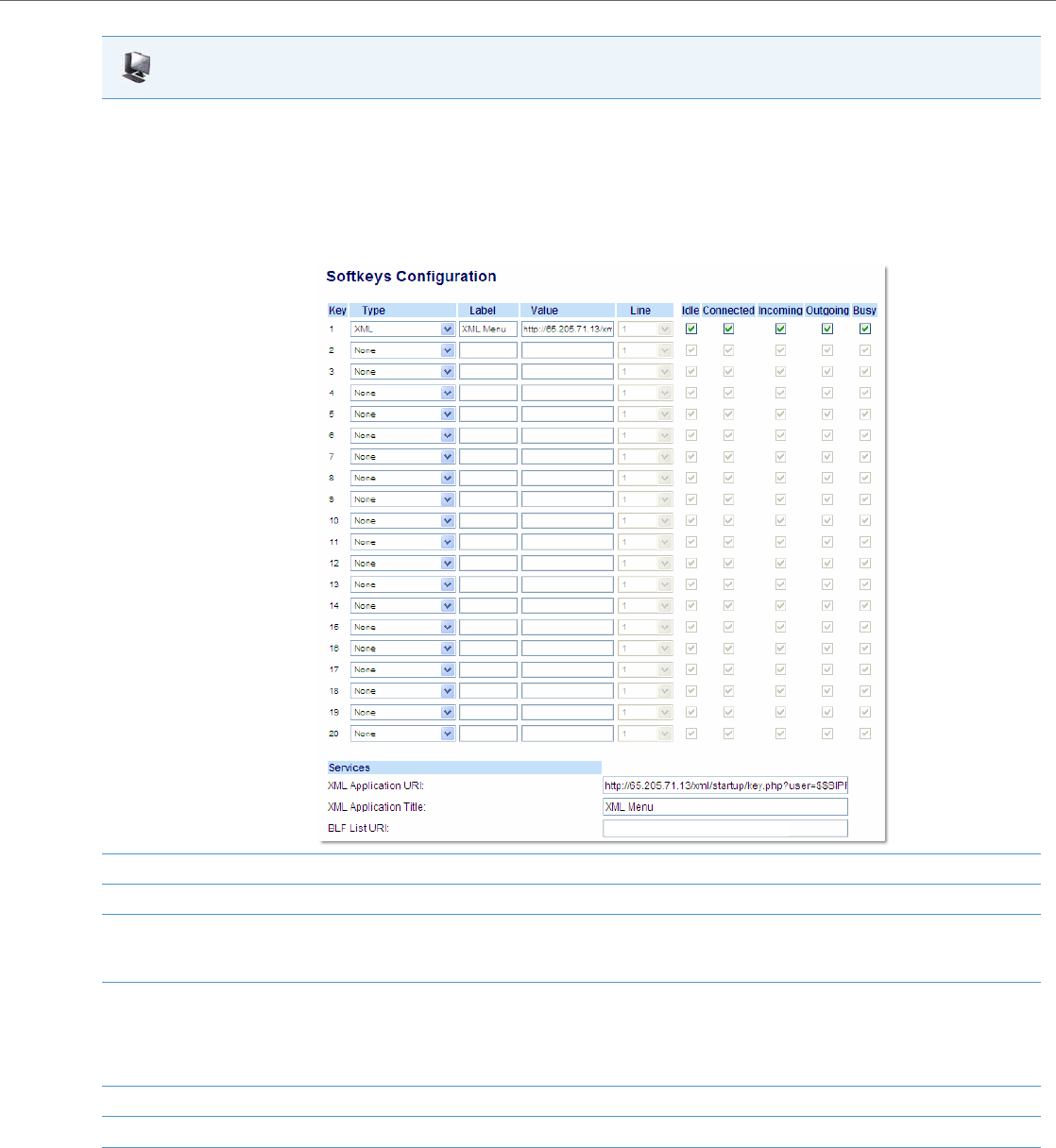
Operational Features
41-001343-02 REV04 – 05.2014 5-103
5. Click on Operation->Softkeys and XML
or
Click on Operation->Programmable Keys
or
Click on Operation->Expansion Module <N>.
Note:
Depending on your phone-model, the key configuration screen displays. The 6755i Key Screen is shown as an example.
6. Select a softkey or programmable key to configure.
7. In the "Type" field, select "XML”.
8. For 8 and 11-Line LCD softkeys:
In the "Label" field, enter the name of the person who’s extension you are monitoring.
9. In the "Value" field, enter the URI that the phone uses to display the XML application to the LCD.
For example, http://65.205.71.13/xml/startup/key.php?user=$$SIPREMOTENUMBER$$.
Note:
For more information about creating an XML script to use with Directed Call Pickup, see the Aastra XML Developer’s Guide.
10. Select the line state (idle, connected, incoming, outgoing, busy) that you want to apply to the XML softkey or programmable key.
11. Click Save Settings to save your changes.
Aastra Web UI

Operational Features
5-104 41-001343-02 REV04 – 05.2014
Softkeys/Programmable Keys/Feature Keys/Expansion Module Keys
You can configure the softkeys, programmable keys, feature keys, and expansion module keys that are applicable to a
specific phone model, to perform specific functions on the IP phones.
Softkeys
The following table provides the number of softkeys you can configure, and the number of lines available for each phone
model that has configurable softkeys.
*The M670i expansion module consists of 36 softkeys. You can have up to 3 expansion modules on an IP phone totalling
108 softkeys. Valid for 6735i, 6737i, 6739i, 6753i, 6755i, 6757i, and 6757i CT phones.
**The M675i expansion module consists of 60 softkeys. You can have up to 3 expansion modules on an IP phone total-
ling 180 softkeys. Valid for 6735i, 6737i, 6739i, 6755i, 6757i, and 6757i CT phones.
***The M680i expansion module consists of 16 softkeys. You can have up to 3 expansion modules on an IP phone total-
ling 48 softkeys. Valid for 6865i and 6867i phones.
Note:
When entering definitions for softkeys in the configuration files, the “#” sign must be enclosed in quotes.
IP Phone Model Softkeys Expansion Module Keys Programmable Keys Lines Available Handset Keys
Available
9480i 6 Not Applicable - 9 -
9480i CT 6 Not Applicable - 9 15
6735i 6 36 to 108*
(Model M670i)
60 to 180**
(Model M675i)
69-
6737i 12 36 to 108*
(Model M670i)
60 to 180**
(Model M675i)
-9-
6739i 55 36 to 108*
(Model M670i)
60 to 180**
(Model M675i)
-9-
6755i 6 36 to 108*
(Model M670i)
60 to 180**
(Model M675i)
69-
6757i 12 36 to 108*
(Model M670i)
60 to 180**
(Model M675i)
-9-
6757i CT 12 36 to 108* on Base Station
(Model M670i)
60 to 180** on Base Station
(Model M675i)
-915
6867i 10 16 to 48***
(Model M680i)
-9-

Operational Features
41-001343-02 REV04 – 05.2014 5-105
State-Based Softkeys
Users and administrators can configure a specific state to display when a softkey is being used. Available states you can
configure for each softkey include:
•idle - The phone is not being used.
•connected - The current line is in an active call (or the call is on hold)
•incoming - The phone is ringing.
•outgoing - The user is dialing a number, or the far-end is ringing.
•busy - The current line is busy because the line is in use or the line is set as “Do Not Disturb”.
The following table identifies the applicable default states for each type of softkey you can configure on the IP phone.
Softkey Type Default States
None All states disabled.
Line idle, connected, incoming, outgoing, busy
Speeddial idle, connected, incoming, outgoing, busy
DND idle, connected, incoming, outgoing, busy
BLF idle, connected, incoming, outgoing, busy
BLF List idle, connected, incoming, outgoing, busy
Auto Call Distribution (ACD) idle
Directed Call Pickup (DCP) (This feature is not supported for the
6735i, 6737i, 6863i, 6865i, and 6867i in Release 3.3.1 SP3.)
Group Call Pickup (GCP) (This feature is not supported for the
6735i, 6737i, 6863i, 6865i, and 6867i in Release 3.3.1 SP3.)
idle, connected, incoming, outgoing, busy
XML idle, connected, incoming, outgoing, busy
Flash All states disabled.
Sprecode connected
Park connected
Pickup idle, outgoing
Last Call Return idle, connected, incoming, outgoing, busy
Call Forward idle, connected, incoming, outgoing, busy
BLF/Xfer idle, connected, incoming, outgoing, busy
Speeddial/Xfer idle, connected, incoming, outgoing, busy
Speeddial/Conf idle, connected, incoming, outgoing, busy
Speeddial/MWI (This feature is not supported for the 6735i,
6737i, 6863i, 6865i, and 6867i in Release 3.3.1 SP3.) idle, connected, incoming, outgoing, busy
Directory idle, connected, incoming, outgoing, busy
Filter (This feature is not supported for the 6735i, 6737i, 6863i,
6865i, and 6867i in Release 3.3.1 SP3.) idle, connected, incoming, outgoing, busy
Callers List idle, connected, incoming, outgoing, busy
Redial idle, connected, incoming, outgoing, busy
Conference idle, connected, incoming, outgoing, busy
Transfer idle, connected, incoming, outgoing, busy
Icom (Intercom) idle, connected, incoming, outgoing, busy
Services idle, connected, incoming, outgoing, busy
Phone Lock All states disabled.

Operational Features
5-106 41-001343-02 REV04 – 05.2014
You can enable or disable the softkey states using the configuration files or the Aastra Web UI. In the Aastra Web UI, you
disable a state by unchecking the box for that operational state.
In the configuration files, you use the following parameters to enable and disable operational states:
•softkeyN states
You can enter multiple values (idle, connected, incoming, outgoing, busy) for the "softkeyN state" parameter. For
example:
softkeyN states: idle connected
You must associate the softkeyN state parameter with a specific softkey. In the following example, the softkeyN states
parameter is associated with softkey 12:
softkey12 type: speeddial
softkey12 label: voicemail
softkey12 value *89
softkey12 states: outgoing
Configuration Example
The following example illustrates the use of the "softkeyN states" parameter, and the "softkeyN type" parameter with a
value of empty. For clarity purposes, only the "softkeyN type" and "softkeyNstates" parameters are shown.
softkey1 type: line
softkey1 states: idle connected
softkey3 type: dnd
softkey3 states: idle
softkey4 type: line
softkey5 type: empty
softkey5 states: connected
softkey6 type: speeddial
softkey6 states: connected
Paging All states disabled.
Empty idle, connected, incoming, outgoing, busy
Notes:
•By default the IP phone idle screen collapses the softkeys. So in the previous example, softkey 12 will appear in posi-
tion 1 if no other softkeys are set.
•A softkey type of "empty" does not display on the idle screen at all. For more information about the softkey type of
"empty" see Appendix A, the section, “Softkey Settings” on page A-158.
Softkey Type Default States

Operational Features
41-001343-02 REV04 – 05.2014 5-107
The following table shows how the keys in the example above would display on the IP Phone UI.
Softkeys and programmable keys are configurable using the Aastra Web UI or the configuration files.
Programmable Keys
The following table provides the number of softkeys and programmable keys you can configure, and the number of lines
available for each type of phone that has programmable keys.
*The M670i expansion module consists of 36 softkeys. You can have up to 3 expansion modules on an IP phone totalling 108
softkeys.
**The M680i expansion module consists of 16 softkeys. You can have up to 3 expansion modules on an IP phone totalling
48 softkeys. Valid for 6865i and 6867i phones.
***On the 6753i, two of the 6 programmable keys are the DELETE and SAVE keys and can be programmed only if Adminis-
trator allows.
Note:
The "empty" key type allows a softkey to be removed quickly by deleting the softkey information from the configura-
tion file.
Softkey Idle Connected Notes
softkey1 Key 1 Key 2 Line displays for softkey1.
Key 1 in connected state is the Drop key. Idle and connected dis-
play as applicable.
softkey2 (not used) (not used) Softkey2 is not displayed.
softkey3 Key 2 (not used) DND displays for softkey3. Idle displays as applicable.
softkey4 Key 3 Key 3 Line displays for softkey4. Default state values (idle, connected,
incoming, outgoing) display as applicable.
softkey5 (not used) Key 4 (blank) A blank displays for softkey5. Connected displays as applicable.
softkey6 (not used) Key 5 Speeddial displays for softkey6. Connected displays as applica-
ble.
IP Phone Model Softkeys Expansion Module Keys Programmable Keys Lines Available Handset Keys
Available
9143i - Not Applicable 7 9 -
6730i - Not Applicable 8 6 -
6731i - Not Applicable 8 6 -
6735i 6 36 to 108*
(Model M670i)
60 to 180**
(Model M675i)
69-
6753i - 36 to 108*
(Model M670i)
6*** 9 -
6755i 6 36 to 108*
(Model M670i)
60 to 180**
(Model M675i)
69-
6863i - Not Applicable 3 2 -
6865i - 16 to 48**
(Model M680i)
89-

Operational Features
5-108 41-001343-02 REV04 – 05.2014
Softkey/Programmable Key/Expansion Module Key Functions
You can configure the softkeys and programmable keys on the phones and any attached expansion module keys to per-
form specific functions using the configuration files or the Aastra Web UI.
The following table identifies the available functions of the softkeys, programmable keys, and expansion module keys on
the IP phones. Available functions may vary on each model phone.
Key Functions Table
Note:
On the 6739i, you can also configure softkeys using the IP Phone UI. For more information, see the Aastra Model 6739i
IP Phone User Guide.
Note:
These functions apply to all model phones unless specifically indicated that the function does not apply.
Softkey/Programma-
ble Key Function Configuration File
Parameter Aastra Web UI
Parameter Description
None none None Indicates not setting for the key.
Line line Line Indicates the key is configured for line use.
Speeddial speeddial Speeddial Indicates the key is configured for speeddial use.
You can configure a softkey to speeddial a specific number. Optionally,
you can also configure a Speeddial key to dial prefix numbers. With this
option, the prefix numbers automatically dial when you press the softkey,
and the phone waits for you to enter the remaining numbers to dial out.
For more information about speeddial prefixes, see “Speeddial Prefixes”
on page5-128.
You can also create Speeddial keys and edit the keys using the IP Phone
keypad. For more information about Speeddial keys and editing Speed-
dial keys, see your <Model-Specific> IP Phone User Guide for more infor-
mation.
Busy Lamp Field (BLF) blf BLF Indicates the key is configured for Busy Lamp Field (BLF) use. A user can
dial out on a BLF configured key. You can also set a BLF subscription
period.
For more information about BLF, see the section “Busy Lamp Field (BLF)”
on page5-128.
For more information about BLF Subscription Period, see “BLF Subscrip-
tion Period” on page5-137.
Busy Lamp Field List list BLF/List Indicates the key is configured for BLF list use. A user can dial out on a
BLF/List configured key.
For more information on BLF, see the section “Busy Lamp Field (BLF)” on
page5-128.
Auto Call Distribution
(ACD) acd Auto Call Distribution (For Sylantro Servers) Indicates the key is configured for automatic call dis-
tribution (ACD). ACD allows the Sylantro Server to distribute calls from a
queue to registered IP Phones (agents). You can also set an ACD subscrip-
tion period.
For more information about ACD, see the section “Automatic Call Distribu-
tion (ACD) (for Sylantro Servers)” on page5-147.
For more information about ACD subscription period, see “ACD Subscrip-
tion Period” on page5-150.

Operational Features
41-001343-02 REV04 – 05.2014 5-109
Directed Call Pickup
(DCP)/Group Call Pickup
(GCP)
dcp Directed Call Pickup (This feature is not supported for the 6735i, 6737i, 6863i, 6865i, and 6867i
in Release 3.3.1 SP3).
(For Sylantro Servers) Indicates the key is configured for either Directed
Call Pickup or Group Call Pickup. The DCP/GCP feature allows you to inter-
cept - or pickup - a call on a monitored extension(s).
For more information about DCP/GCP, see the section “Directed Call
Pickup/Group Call Pickup” on page5-151.
Do Not Disturb (DND) dnd Do Not Disturb Indicates key is configured for "do not disturb" use.
For more information on DND, see the section “Do Not Disturb (DND)” on
page5-154.
Extensible Markup Lan-
guage) (XML) xml XML Indicates the key is configured to accept an XML application for accessing
customized XML services. You can also specify a URL for an XML key.
For more information on XML, see the section “XML Customized Services”
on page5-239.
Flash flash Flash Indicates the key is set to generate a flash event when it is pressed, or
when a feature key is pressed on the 6757i CT handset. The IP phone gen-
erates flash events only when a call is connected and there is an active RTP
stream (for example, when the call is not on hold).
For more information about the Flash key, see your <Model-Specific> IP
Phone User Guide.
Sprecode sprecode Sprecode Indicates the key is set to automatically activate specific services offered
by the server. For example, if the sprecode value of *82 is configured, then
by pressing the key, *82 automatically activates a service provided by the
server. The value you enter for this field is dependent on the services pro-
vided by the server.
For more information about the Sprecode key, see your <Model-Specific>
IP Phone User Guide.
Park park Park Indicates the key is set to be used as a park key to park an incoming call.
For more information on park, see the section “Park/Pick Up Static and
Programmable Configuration” on page5-177.
Pickup pickup Pickup Indicates the key is set to be used as a pickup key to pick up a parked call.
For more information on pickup, see the section “Park/Pick Up Static and
Programmable Configuration” on page5-177.
Last Call Return (LCR) lcr Last Call Return (For Sylantro Servers) Indicates the key is set to be used to dial the last call
that came in on that line.
For more information on lcr, see the section “When the user presses the
Pickup softkey, the phone will dial out *88 to connect to the pickup orbit,
wait four seconds, automatically send the pickup dial code of 42, and then
at this time the user can enter the last two digits of the pickup extension to
complete the call pickup.” on page5-186.
Call Forward callforward Call Forward Indicates the key is set to be used to access the Call Forward menus on the
phone.
For more information about call forwarding, see the section “Call Forward-
ing” on page5-190.
BLF/Xfer blfxfer Call Forward Indicates the key is set to be used as a BLF key AND as a Transfer key.
For more information about the BLF/Xfer feature, see the section “Use the
following parameters to configure the ring splashsettings:” on page5-
137.
Softkey/Programma-
ble Key Function Configuration File
Parameter Aastra Web UI
Parameter Description

Operational Features
5-110 41-001343-02 REV04 – 05.2014
Speeddial/Xfer speeddialxfer Speeddial/Xfer Indicates the key is set to be used as a Speeddial key AND as a Transfer key.
For more information about the Speeddial/Xfer feature, see the section
“Use the following parameters to configure the ring splashsettings:” on
page5-137.
Speeddial/Conf speeddialconf Speeddial/Conf Indicates the key is set to be used as a Speeddial key AND as a Conference
key.
For more information about the Speeddial/Conf feature, see the section
“Speeddial/Conference Key” on page5-141.
Speeddial/MWI speeddialmwi Speeddial/MWI (This feature is not supported for the 6735i, 6737i, 6863i, 6865i, and 6867i
in Release 3.3.1 SP3).
Indicates the key is set to be used as a Speeddial key for a voicemail
account.
For more information about the Speeddial/MWI feature, see the section
“Speeddial/MWI Key” on page5-143.
Directory directory Directory Indicates the key is set for accessing the Directory List.
For more information about the Directory List, see the section “Directory
List” on page5-226.
Filter filter Filter (This feature is not supported for the 6735i, 6737i, 6863i, 6865i, and 6867i
in Release 3.3.1 SP3).
Indicates the key is set for activating/deactivating Executive Call Filtering.
For more information about the Executive and Assistant Services feature,
see the section “BroadSoft BroadWorks Executive and Assistant Services
Feature” on page6-44.
Callers List callers Callers List Indicates the key is set for accessing the Callers List.
For more information on the Callers List, see the section “Callers List” on
page5-221.
Redial List redial Redial Indicates the key is configured to access the Redial List.
For more information about the Redial List, see your <Model-Specific> IP
Phone User Guide.
Conference conf Conference Indicates the key is configured as a Conference key (for local conferenc-
ing).
(For Sylantro and Broadsoft Servers) An Administrator can also enable
centralized conferencing on the IP Phones.
For more information about using the Conference key, see your <Model-
Specific> IP Phone User Guide.
For information about enabling centralizing conferencing, see “Central-
ized Conferencing (for Sylantro and Broadsoft Servers)” on page5-266.
Transfer xfer Transfer Indicates the key is configured as a Transfer key for transferring calls.
For more information about using the Transfer key, see your <Model-Spe-
cific> IP Phone User Guide.
Icom icom Intercom Indicates the key is set to be used as the Intercom key. For more informa-
tion about using the Intercom key, see your <Model-Specific> IP Phone
User Guide.
For information about other Intercom features, see “Incoming/Outgoing
Intercom with Auto-Answer and Barge In” on page5-79.
Softkey/Programma-
ble Key Function Configuration File
Parameter Aastra Web UI
Parameter Description

Operational Features
41-001343-02 REV04 – 05.2014 5-111
Reference
For more information about key functions for your model phone, see your <Model-Specific> IP Phone User Guide.
Configuring Softkeys and Programmable Keys
Use the following procedures to configure the softkeys and programmable keys on the IP phone.
Services services Services Indicates the key is set to access Services, such as, Directory List, Callers
List, Voicemail, and any other XML applications configured on the phone.
For more information about using the Services key, see your <Model-Spe-
cific> IP Phone User Guide.
Phone Lock
(Not applicable to the
cordless handsets on CT
models)
phone lock Phone Lock Indicates the key is configured as a phone lock key, allowing you to press
this key to lock/unlock the phone.
For more information about the lock/unlock key, see “Locking IP Phone
Keys” on page5-49.
Paging paging Paging Indicates the softkey is set for Group Paging on the phone. Pressing this
key automatically sends a Real Time Transport Protocol (RTP) stream to
pre-configured multicast addresses without involving SIP signaling.
For more information about the Paging key, see “Group Paging RTP Set-
tings” on page5-82.
Empty
(Not applicable to pro-
grammable keys or
expansion module keys)
empty Empty Indicates the key is configured to force a blank entry on the IP phone dis-
play for a specific key. If a particular key is not defined, it is ignored.
For more information about empty keys, see your <Model-Specific> IP
Phone User Guide.
Configuration Files
For specific parameters you can set in the configuration files, see Appendix A, the sections, “Softkey/Programmable Key/Keypad Key/Feature
Key/Expansion Module Key/Hard Key Parameters” on pageA-156.
Softkey/Programma-
ble Key Function Configuration File
Parameter Aastra Web UI
Parameter Description
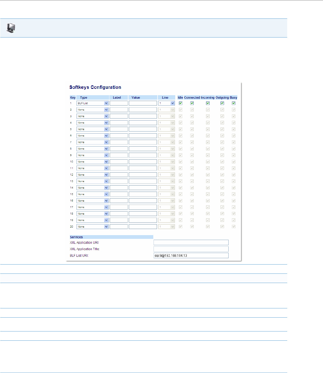
Operational Features
5-112 41-001343-02 REV04 – 05.2014
Aastra Web UI
1. Click on Operation->Softkeys and XML
or
Click on Operation->Programmable Keys
or
Click on Operation->Expansion Module <N>.
Depending on your phone-model, the key configuration screen displays. The 6755i Key Screen is shown as an example.
2. Select a key to configure.
For Softkeys and Expansion Module Keys:
3. In the "Type" field, select the type of softkey you want to configure.
Reference: For available type values on each IP phone model, see Appendix A, the section, “Softkey/Programmable Key/Keypad Key/Fea-
ture Key/Expansion Module Key/Hard Key Parameters” on pageA-156.
4. If applicable, enter a label in the “Label” field.
5. If applicable, in the "Value" field, enter a value to associate with the softkey. For example, for a Speeddial value, you can enter a number you
want to use for the Speeddial key, or 12345+ as a Speeddial prefix.
6. If applicable, in the "Line" field, select the line for which you want to associate the softkey.
7. Some softkey types allow you to configure specific operational states.
Operational states display to the IP phone when a softkey is used.
To enable/disable an operational state, click the "Idle", "Connected", "Incoming", or "Outgoing" fields to check or uncheck the box.
Operational states are not applicable to expansion modules.
8. Click Save Settings to save your changes.

Operational Features
41-001343-02 REV04 – 05.2014 5-113
Shifting of Softkey Positions for Busy States
Administrators can shift the softkey position for busy states using the “collapsed context user softkey screen” parame-
ter. If this parameter is configured, user programmable softkeys on the 6735i, 6737i, 6755i, 6757i, 6757iCT, 9480i, and
9480iCT phones will collapse and fill in any unused softkeys starting on the first page of softkeys during the following
states:
•outgoing
•ringing
•connected
•hold
For Example:
During a call on a 6755i IP phone with this parameter disabled and with softkey 1 configured as Park and softkey 2 config-
ured as DND, these two softkeys will not appear on page 1. The user has to press the More key to access them on page 2.
During a call on a 6755i IP phone with the “collapsed context user softkey screen” parameter enabled Park and DND
appear on page 1 in softkey positions 4 and 5 (Drop, Conf, and Xfer situated in softkey positions 1, 2, and 3).
Configuring Collapsed Context User Softkey Screen
Use the following procedures to configure the collapsed context user softkey screen.
Option to Remove the “More” Softkey when Not Required
Administrators can control how softkeys are displayed on the IP phones’ screens when the number of softkeys configured
matches the exact number of softkey buttons on the phone.
For Programmable Keys:
9. In the “Hard Key” field, select the programmable key type you want to configure.
Reference: For available type values on each IP phone model, see Appendix A, the section, “Softkey/Programmable Key/Keypad Key/Fea-
ture Key/Expansion Module Key/Hard Key Parameters” on pageA-156.
10. In the "Value" field, enter a value to associate with the programmable key. For example, for a Speeddial value, you can enter a number you
want to use for the Speeddial key, or 12345+ as a Speeddial prefix.
11. In the "Line" field, select the line for which you want to associate the programmable key.
12. Click Save Settings to save your changes.
Note:
Applicable to the 6735i, 6737i, 6755i, 6757i, 6757iCT, 9480i, and 9480iCT IP Phones only.
Note:
The phone defined context-sensitive softkeys (including empty/unassigned keys) will remain in the same location.
Configuration Files
For specific parameters you can set in the configuration files, see Appendix A, the section, “Shifting of Softkey Positions for Busy States” on pageA-164.
Note:
Applicable to the the 9480i, 9480i CT, 6735i, 6737i, 6739i, 6755i, 6757i, 6757i CT IP, and 6867i IP phones only.
Aastra Web UI

Operational Features
5-114 41-001343-02 REV04 – 05.2014
For example, with the 9480i, 9480i CT, 6735i, and 6755i IP phone has a total of six physical softkey buttons. By default,
when a total of six softkeys are configured, the screen displays five softkeys and offers a “More” option to access the
remaining softkey.
By enabling the “collapsed more softkey screen” parameter, in the scenario above, the “More” softkey is removed
allowing the phones to display all six configured softkeys on one screen.
01/01/14 11:00am
L1 Thomas Keller
Services DND
Directory Paging
Callers More
01/01/14 11:00am
L1 Thomas Keller
Lock
More
Default Screen 1
Default Screen 2
01/01/14 11:00am
L1 Thomas Keller
Services DND
Directory Paging
Callers Lock

Operational Features
41-001343-02 REV04 – 05.2014 5-115
When the “collapsed more softkey screen” parameter is enabled for the 6737i, 6757i, or 6757i CT the phone will apply
the same behavior if six top softkeys or six bottom softkeys are configured.
Icom CFWD
Park LCR
Pickup More
Services DND
Directory Paging
Callers More
01/01/14 11:00am
L1 Thomas Keller
Icom CFWD
Park LCR
Pickup Home
Services DND
Directory Paging
Callers Lock
01/01/14 11:00am
L1 Thomas Keller
Default Screen 1
Parameter Enabled
Home
More
Lock
More
01/01/14 11:00am
L1 Thomas Keller
Default Screen 2
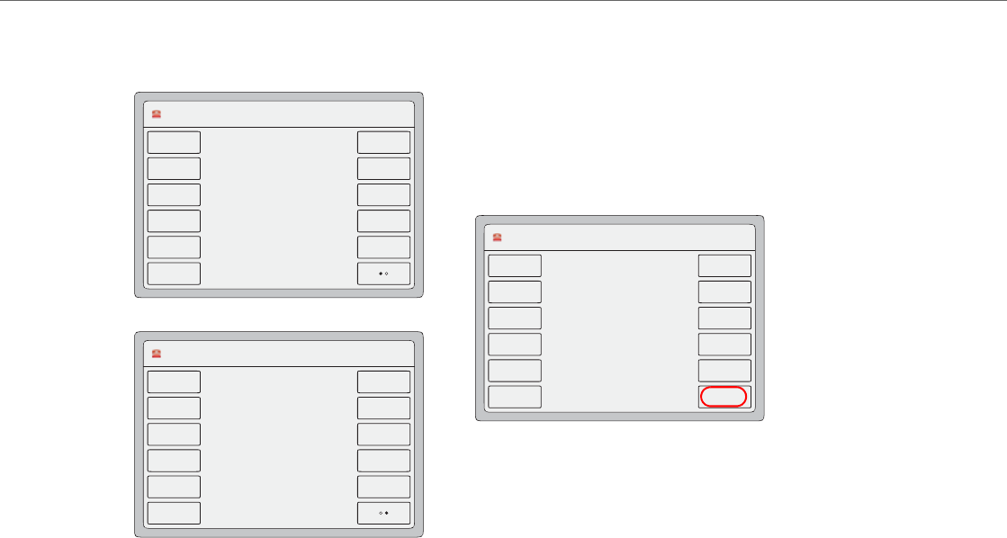
Operational Features
5-116 41-001343-02 REV04 – 05.2014
When the “collapsed more softkey screen” parameter is enabled for the 6739i IP phone, the phone will apply the same
behavior if a total of 12 softkeys are configured.
Default Screen 1
Parameter Enabled
L1 Thomas Keller 11 : 40am
13/05/13
Thomas Keller
Line 4
Line 5
Line 6
Paging
DND
Lock
Park
Pickup
CFWD
LCR
Icom
L1 Thomas Keller 11 : 40am
13/05/13
Thomas Keller
Line 4
Line 5
Line 6
Paging
DND
Lock
Park
Pickup
CFWD
LCR
Icom
Home
L1 Thomas Keller 11 : 40am
13/05/13
Thomas Keller
Home
Default Screen 2
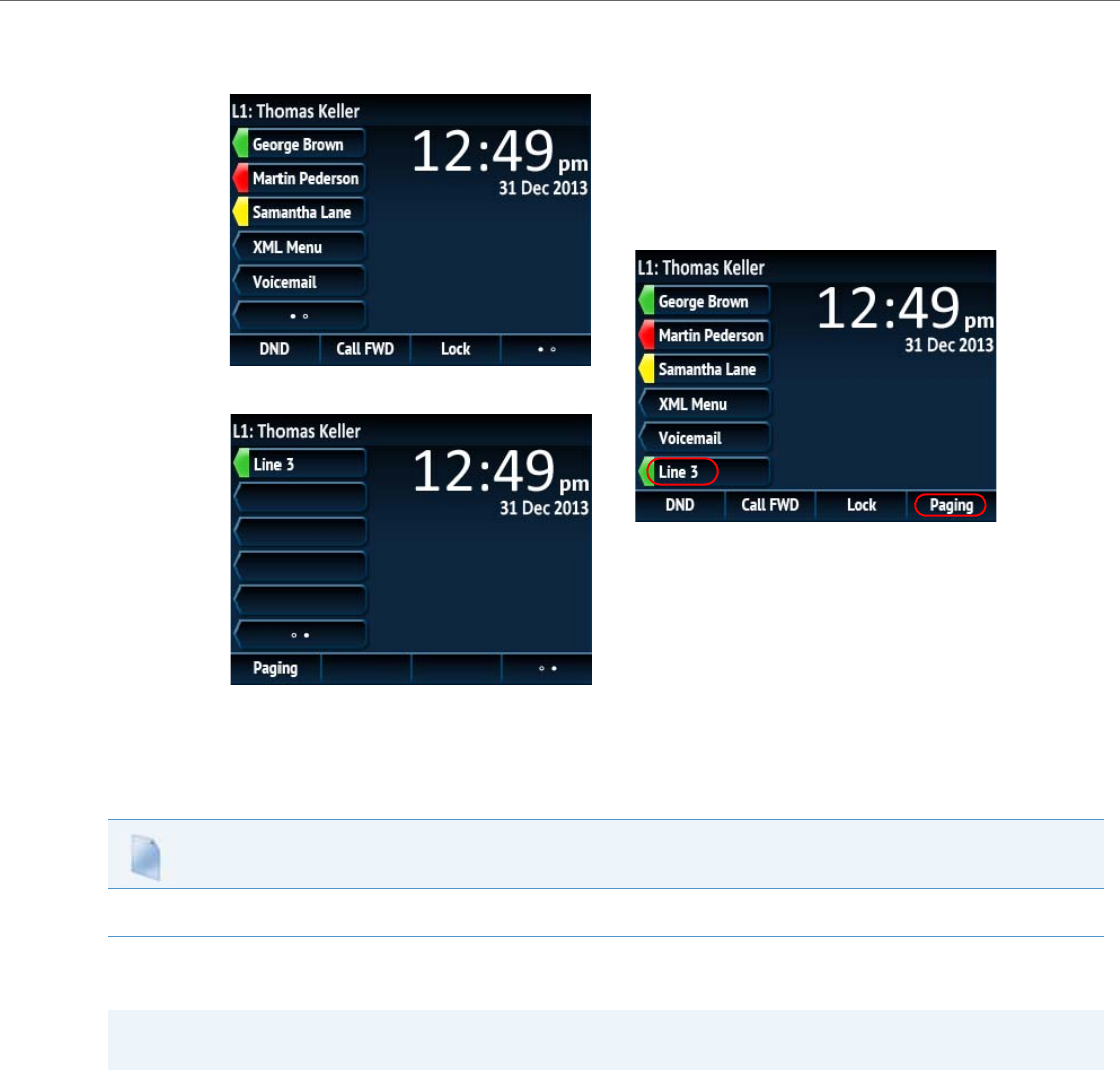
Operational Features
41-001343-02 REV04 – 05.2014 5-117
When the “collapsed more softkey screen” parameter is enabled for the 6867i IP phone, the phone will apply the same
behavior if six top softkeys or four bottom softkeys are configured.
Configuring the Collapsed More Softkey Screen Option
Use the following parameter to configure the collapsed more softkey screen option:
Increased Number of Displayed Characters for Softkey Line Labels
Administrators can now choose to display 10 characters on softkeys and top softkeys for line labels on 6735i, 6737i, 6755i,
6757i, and 6757i CT model phones. This is useful if the user wants to display a full 10 digit number as the softkey label,
instead of a shortened label containing only 7 digits followed by ellipsis characters.
When a softkey or top softkey is defined as a line, the circle in front of the softkey label (line icon) can be removed using
the new “line icon disabled” parameter. When the “line icon disabled” parameter is set to “1”, the line icon will not
appear and the label can be displayed with up to 10 characters (label will not be shortened and no ellipsis characters will
appear).
Configuration Files
For specific parameters you can set in the configuration files, see Appendix A, the section, “Increase of Displayed Characters for Softkey Line Labels”
on pageA-165.
Note:
Applicable to the 6735i, 6737i, 6755i, 6757i, and 6757iCT IP Phones only.
Default Screen 1
Parameter Enabled
Default Screen 2

Operational Features
5-118 41-001343-02 REV04 – 05.2014
Configuring the Increase of Displayed Characters for Softkey Line Labels
Use the following parameter to disable the line icon and increase the number of characters displayed for softkey line
labels:
6757i Cordless (CT) Feature Keys
In addition to the softkeys on the 6757i CT, this phone also has handset keys you can configure with specific features.
You can use the Aastra Web UI to configure the handset keys.
You can program up to 15 feature keys on the 6757i CT handset with specific functions using the Aastra Web UI.
The following table identifies the functions available for all 15 handset keys and the default functions for each key.
Feature Key Programming Guidelines
The following are guidelines to use when programming the feature keys on the handset:
•All handsets paired with the same Base Station have the same programmed functions since the web interface applies
the functions to all the handsets paired with that base.
•A newly registered handset or handset that was out-of-range during the programming needs to perform an "off-hook
and on-hook" sequence in order for the newly programmed function to be broadcasted to the affected handsets.
Simply press the v key from the idle state to go off-hook. Then, press the y key to go back on-hook.
•Duplicate functions can exist in the feature key as there is no filtering or duplicate checking done on the handset or
Configuration Files
For specific parameters you can set in the configuration files, see Appendix A, the section, “Increase of Displayed Characters for Softkey Line Labels”
on pageA-165.
Note:
You configure the handset keys using the Aastra Web UI (Operation->Handset Keys) or by pressing the "F" button on
the handset.
Handset Key Key Function Description
1 Line 1 Line 1 key - Selects line one
2 Line 2 Line 2 key - Selects line two
3 Line 3 Line 3 key - Selects line three
4 Line 4 Line 4 key - Selects line four
5 Icom Icom key – Enter handset list to select handset to call
6 Dir Directory key – Activate directory feature
7CallersCallers key – Activate callers feature
8 Xfer Transfer key - Activate transfer feature
9 Conf Conference key - Activate conference feature
10 Public Public key – Toggle between public & private call mode
11 None No function selected. Line 5 key (if available) - Selects line five.
12 None No function selected. Line 6 key (if available) - Selects line six.
13 None No function selected. Line 7 key (if available) - Selects line seven.
14 None No function selected. Line 8 key (if available) - Selects line eight.
15 None No function selected. Line 9 key (if available) - Selects line nine.

Operational Features
41-001343-02 REV04 – 05.2014 5-119
the base.
•If no line keys are programmed for the feature key, the handset is restricted to intercom calls only.
•If all 12 programmable functions have been programmed to "None", the user is presented with a List empty message
when the feature key is pressed.
•For security reasons, the user has 180 seconds (3 minutes) to complete the programming. Otherwise, the phone dis-
plays the following error:
** Error **: Session expired, Please reload page.
•For security reasons, the user must submit the page from the same browser that was used to load the page. If the user
tries to submit the page from any other IP address, the following error displays:
** Error ** Session invalid. Different Client IP Addresses. — Please reload page
Handset Feature Key Functions
You can configure the features keys on the 6757i CT handset to perform specific functions using the configuration files or
the Aastra Web UI.The following table identifies the available functions for the feature keys on the 6757i CT handset.
The following Handset Key Functions Table lists the available functions for the keys on the 6757i CT IP Phone.
List empty
Use web page to
configure

Operational Features
5-120 41-001343-02 REV04 – 05.2014
Handset Key Functions Table
Feature Key Function Configuration File
Parameter Aastra Web UI
Parameter Description
None none None Indicates the key is disabled.
This option is available from Web UI only.
Line
(Lines 1 through 9 are
available for selection)
line Line Indicates the key is configured for line use.
Icom icom Icom Indicates the key is set to be used as the Intercom key.
For more information about the Icom key, see your Aastra IP Phone 6757i
CT User’s Guide.
For information about other Intercom features, see “Incoming/Outgoing
Intercom with Auto-Answer and Barge In” on page5-79.
Directory dir Dir Indicates the key is set for accessing the Directory List.
For more information about the Directory List, see the section “Directory
List” on page5-226.
Callers callers Callers Indicates the key is set for accessing the Callers List.
For more information on the Callers List, see the section “Callers List” on
page5-221.
Transfer xfer Xfer Indicates the key is configured as a Transfer key for transferring calls.
For more information about the Xfer key, see your Aastra IP Phone 6757i
CT User’s Guide.
Park park Park Indicates the key is set to be used as a park key to park an incoming call.
For more information on park, see the section “Park/Pick Up Static and Pro-
grammable Configuration” on page5-177.
Pickup pickup PickUp Indicates the key is set to be used as a pickup key to pick up a parked call.
For more information on pickup, see the section “Park/Pick Up Static and
Programmable Configuration” on page5-177.
Conference conf Conf Indicates the key is configured as a Conference key (for local conferencing).
(For Sylantro and Broadsoft Servers) An Administrator can also enable cen-
tralized conferencing on the IP Phones.
For more information about using the Conference key, see your Aastra IP
Phone 6757i CT User’s Guide.
For information about enabling centralizing conferencing, see “Centralized
Conferencing (for Sylantro and Broadsoft Servers)” on page5-266.

Operational Features
41-001343-02 REV04 – 05.2014 5-121
Reference
For more information about features key functions for your 6757i CT, see your Aastra IP Phone 6757i CT User’s Guide.
Configuring Handset Feature Keys
You can program up to 15 feature keys on the 6757i CT IP phone using the configuration files or the Aastra Web UI. Use the
following procedure to program the feature keys on your 6757i CT Base Station and all paired handsets.
Use the following procedures to configure the IP phone handset feature keys.
Public public Public Indicates the key is configured to toggle from public to private mode. A
public and private key can be used when at a line item in the Directory List.
The Private key toggles a number in the Directory List to private. The Pub-
lic key allows a number in the Directory List to be sent to the handsets. A
6757i CT accepts a maximum of 50 entries with the public attribute.
For more information about the public/private keys, see your Aastra IP
Phone 6757i CT User’s Guide.
Flash flash Flash Indicates the key is set to generate a flash event when it is pressed, or when
a feature key is pressed on the 6757i CT cordless handset. The IP phone
generates flash events only when a call is connected and there is an active
RTP stream (for example, when the call is not on hold).
For more information about the Flash key, see your Aastra IP Phone 6757i
CT User’s Guide.
Configuration Files
For specific parameters you can set in the configuration files, see Appendix A, the section,“Handset Feature Key Settings” on pageA-175.
Feature Key Function Configuration File
Parameter Aastra Web UI
Parameter Description
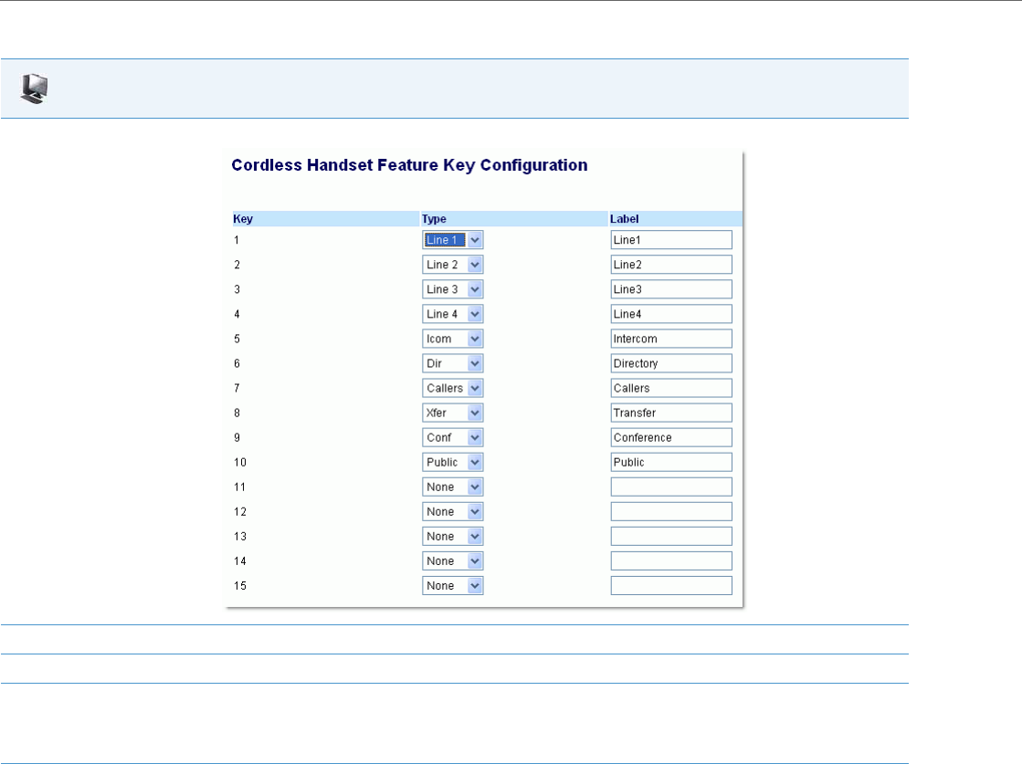
Operational Features
5-122 41-001343-02 REV04 – 05.2014
Aastra Web UI
1. Click on Operation->Handset Keys.
2. Select the handset key you want to program.
3. Select the function for that handset key from the "Key Function" field.
4. Click Save Settings to save the function you selected to the handset key.
The key programming information is sent to the 6757i Base Station and to all the cordless handsets associated with that Base Station. Any
key programmed to "None" does not appear in the handset’s list.
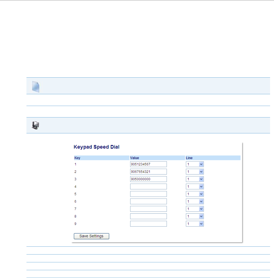
Operational Features
41-001343-02 REV04 – 05.2014 5-123
Press-and-Hold Speeddial Keypad Keys
The keypad keys on the IP phones can be used to store speeddial numbers that are dialed out when a user presses and
holds the respective key. These press-and-hold speeddial numbers can be configured using the IP phone UI, the Aastra
Web UI, or by defining the “pnhkeypadN value” and “pnhkeypadN line” parameters in the configuration files.
Configuring Press-and-Hold Speeddial Keypad Keys
You can program one speeddial number for each applicable keypad key (keys 1 through 9). For information on how to
configure the press-and-hold keypad keys using the IP phone UI, please refer to the respective phone model’s Aastra SIP IP
Phone User Guide.
Use the following procedures to configure the press-and-hold keypad keys.
Configuration Files
For specific parameters you can set in the configuration files, see Appendix A, the section,“Press-and-Hold Speeddial Keypad Key Settings” on pageA-
174.
Aastra Web UI
1. Click on Operation->Keypad Speed Dial.
2. Select the keypad key you want to program.
3. In the “Value” field, enter the speeddial number.
4. In the "Line" field, select the line number you want the phone to use when dialing the speeddial number.
5. Click Save Settings.
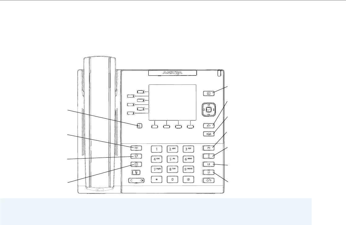
Operational Features
5-124 41-001343-02 REV04 – 05.2014
6867i Hard Key Reprogramming
Administrators have the ability to reprogram 7 of the 6867i IP phone’s hard keys with any one of the phone’s softkey
functions.
6867i Hard Key Mapping
Notes:
•The reprogramming of hard keys 5, 6, 7, and 11 (indicated above in red) is not supported.
•Hard keys are only configurable using the configuration files.
hardkey1
Default type: line
hardkey2
Default type: line
hardkey3
Default type: redial
hardkey4
Default type: callers
hardkey5
Options Key
hardkey6
Hold Key
hardkey7
Goodbye Key
hardkey8
Default type: conf
hardkey9
Default type: xfer
hardkey10
Default type: directory
hardkey11
Presence Key
Default line: 1
Default line: 2
Default value: N/A

Operational Features
41-001343-02 REV04 – 05.2014 5-125
The following parameters can be used to reprogram the hard keys:
Configuration Parameter Description
hardkeyN type The type of key to which you would like to change the hard key. Valid types include:
•none
•line
•speeddial
•dnd
•blf
•list
•acd
•xml
•flash
•sprecode
•park
•pickup
•lcr
•callforward
•blfxfer
•speeddialxfer
•speeddialconf
•directory
•callers
•redial
•conf
•xfer
•icom
•phonelock
•paging
hardkeyN value The value you would like to assign to the hard key you are configuring.
The “hardkeyN value” parameter can be set for the following key types only:
•speeddial
•blf
•sprecode
•xml
•park
•pickup
•blfxfer
•speeddialxfer
•speeddialconf
•paging
hardkeyN line The line associated with the hard key you are configuring.
The “hardkeyN line” parameter can be set for the following key types only:
•speeddial
•blf
•list
•acd
•park
•pickup
•lcr
•blfxfer
•speeddialxfer
•speeddialconf

Operational Features
5-126 41-001343-02 REV04 – 05.2014
In addition to the above basic parameters, the following supplementary parameters can also be used for the hard keys:
Reprogramming Hard Key Functionality Using the Configuration Files
Use the following procedures to reprogram the functionality of hard keys on the IP 6867i IP phone.
Configuration Parameter Description
hardkeyN locked Locks the specified hard key on the IP phones. When enabled, the phone locks the key with the provisioned
local settings and prevents users from changing or configuring the key.
Note:
If no settings are configured locally but the “hardkeyN type” is defined in a configuration file, the phone will
lock the key with the key type defined in the configuration file along with any values associated with the addi-
tional “hardkeyN” parameters (i.e. “hardkeyN value” and “hardkeyN line”).
hardkeyN ring splash When a key is configured for BLF functionality, this parameter controls the ring splash alert pattern per key.
The following alerting patterns are available:
•Silence (ring splash off).
•Normal splash (same as current BLF ring splash).
•Normal - delayed (After a delay of (x) seconds, the normal ring splash is played).
•Periodic (similar to the normal ring signal that is used by the phone itself. The actual ring melody is based
on the current melody set for the line where the BLF key is associated to).
•Periodic - delayed (after a delay of (x) seconds, the ring signal that is used by the phone is played - see
above).
•One low volume splash (same as the current BLF ring splash but at a lower level to be less intrusive).
•One low volume splash - delayed (after a delay of (x) seconds, the ring signal that is the same as the current
BLF ring splash is played at a lower level).
When a key is configured for BLF/List functionality, this parameter controls the ring tone per key. The follow-
ing ring tones are available:
•Ring tone 1
•Ring tone 2
•Ring tone 3
•Ring tone 4
•Ring tone 5
•Silence (ring tone off)
Note:
Ring tones are based on the current ring tone set configured on the IP phone.
Notes:
•The value of “N” in the above “hardkeyN” parameters corresponds to the hard key’s mapping number as per the
“6867i Hard Key Mapping” figure.
•Hard keys 1 to 4 can be remapped to any key type. If applicable, LED indication will follow the colour/cadence of the
corresponding feature when the key is reprogrammed.
•Hard keys 8, 9, and 10 can be remapped to any key type except for the following: Line, BLF, BLF/List, Auto Call Distri-
bution, and BLF/Xfer.
•If a hard key is configured with the type “None”, functionality of the hard key (and its corresponding LED) is disabled.
•Misconfiguration of the hard key will result in the key going back to its default function. For example, reprogramming
hard key 3 (Redial) to
hardkey3 type: line
hardkey3 line: 33
will result in hard key 3 reverting back to its default Redial functionality as the “hardkey3 line: 33” definition is invalid.
Configuration Files
For specific parameters you can set in the configuration files, see Appendix A, the sections, “Hard Key Settings for 6867i” on pageA-182, “Locking Keys”
on pageA-187, and “Ring Splash Settings” on pageA-193.
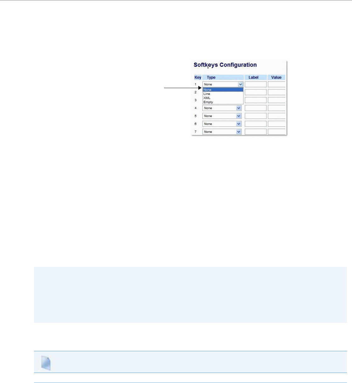
Operational Features
41-001343-02 REV04 – 05.2014 5-127
Customizing the Key Type List in the Aastra Web UI
An Administrator can configure which key types display in the Aastra Web UI list for a Softkey, Programmable Key, Expan-
sion Module Key, and/or Feature Key (CT Models). Currently, in the Aastra Web UI for a phone, you can select a type of key
from a list of more than 20 key types to assign to a softkey, programmable key, expansion module key, and/or feature key.
Using the configuration files, you can specify key types to display in the key type list that apply to a User’s environment.
In addition to being able to specify which key types display in the list, the Administrator can also determine in which order
the key types display.
You can use the following configuration file parameters to control which key types to display and specify in which order to
display them in:
•softkey selection list
•feature key selection list
If no value is specified for the “softkey selection list” and/or “feature key selection list” parameters, the key “Type” list dis-
plays all of the key types by default.
If an Administrator configures specific key types for a phone in the configuration file, and the phone for which he down-
loads the configuration to already has key types configured on it, those key types display in the key list for those keys, in
addition to the key types specified by the Administrator. For example, a phone has a Park key and a Pickup key already
configured on the phone, and the Administrator downloads a configuration file to the phone that has specific key types of
None, Line, Speeddial, and XML. After the configuration file is downloaded, the Park key list will show None, Line, Speed-
dial, XML, and Park; the Pickup key list will show None, Line, Speeddial, XML, and Pickup; all other keys that were config-
ured as None before the download will show only None, Line, Speeddial, and XML.
Customizing the Key Type List Using the Configuration Files
Use the following procedure to configure the Key Type List that displays in the Aastra Web UI.
Notes:
•Any key types configured that do not apply to the phone are ignored.
•The SAVE and DELETE keys appear by default as Keys 1 and 2 on the 6753i and 9143i, and as Keys 5 and 6 on the 6730i
and 6731i, unless your Administrator configured these keys as other functions.
•An Administrator must use the English value when configuring the key types in the configuration files.
•After configuring specific key types for a phone, the key types in the Aastra Web UI display the same for both the User
and Administrator Web interfaces for that phone.
Configuration Files
For specific parameters you can set in the configuration files, see Appendix A, the section, “Customizing the Key Type List” on pageA-185.
Example of a List of
Configured Keys Types
(None, Line, XML, Empty)

Operational Features
5-128 41-001343-02 REV04 – 05.2014
Speeddial Prefixes
The normal function of the Speeddial option allows you to configure a specific key on the phone to dial a number
quickly by pressing the configured key. For example, if you had the following Speeddial configuration in the configura-
tion files:
softkey1 type: speeddial
softkey1 label: Office
softkey1 value: 5552345
softkey1 line: 1
after you press softkey1 on the phone, it dials the Office number at 555-2345 on line 1.
A new feature for the Speeddial option allows you to configure a preset string of numbers followed by a “+”. This feature
allows the phone to speeddial a prefix number and then pause to let you enter the remaining phone number. You can
use this feature for numbers that contain long prefixes. For example, if you had the following Speeddial configuration in
the configuration files:
softkey2 type: speeddial
softkey2 label: Europe Office
softkey2 value: 1234567+
softkey2 line: 2
after you press softkey2 on the phone, it dials the prefix number automatically and pauses for you to enter the remaining
number using the keypad on the phone.
You can configure the Speeddial prefix using the configuration files or the Aastra Web UI.
Enabling/Disabling Ability to Add or Edit a Speeddial Key
The IP Phones allow you to set a parameter, “speeddial edit” using the configuration files that allows you to enable or
disable the ability to add a Speeddial key or edit a Speeddial key from the IP Phone UI. Disabling this parameter prevents
a user from adding or editing a Speeddial key.
The default for this parameter is enabled, allowing you to create and edit Speeddial keys on the phone using the Press-
and-hold feature, softkeys, programmable keys, expansion module keys and key pad, Speeddial menu in the IP Phone UI,
and the SAVE TO key.
If this parameter is set to disabled, it blocks the user from using any of the features on the phone to create or edit a
Speeddial key.
Enabling/Disabling the Ability to Add or Edit a Speeddial Key Using the Configuration Files
Use the following procedure to enable/disable the ability to add and edit a Speeddial key.
Busy Lamp Field (BLF)
The BLF feature on the IP phones allows a specific extension to be monitored for state changes. BLF monitors the status
(busy or idle) of extensions on the IP phone.
Configuration Files
For specific parameters you can set in the configuration files, see Appendix A, the section, “” on pageA-191.
Note:
BLF feature availability is dependant on your call manager.

Operational Features
41-001343-02 REV04 – 05.2014 5-129
Example
A Supervisor configures BLFs on his phone for monitoring the status of a worker’s phone use (busy or idle). When the
worker picks up his phone to make a call, a busy indicator on the Supervisor’s phone shows that the worker’s phone is in
use and busy.
BLF Setting
(For use with Asterisk and sipXecs servers)
On 8 and 11-Line LCD phones, the busy and idle indicators show on the IP phone screen display next to the softkey or pro-
grammable key configured for BLF functionality. When the monitored user is idle, an icon with the handset on-hook
shows next to the BLF softkey or programmable key. When the monitored user is on an active call, a small telephone icon
is shown with the handset off-hook.
On 3-Line LCD phones, the LED lights next to each BLF programmable key illuminate steady to indicate the monitored line
is off-hook or unregistered. The LED goes off when the line is idle.
On the 6739i , the busy and idle states are indicated by icons as well as by the color of the softkey button on screen (i.e. red
for busy, black for idle).
On the 6867i, the busy and idle states are indicated by the color of the softkey button on screen (i.e. red for busy, green for
idle) as well as the LED indicators (i.e. solid for busy and off for idle).
You can configure a BLF key on the IP Phones using the configuration files or the Aastra Web UI.
BLF/List Setting
(For use with the BroadSoft Broadworks Rel 13 or higher platform only)
The BLF/List feature on the IP phones is specifically designed to support the BroadSoft Broadworks Rel 13 Busy Lamp Field
feature. This feature allows the IP phone to subscribe to a list of monitored users defined through the BroadWorks web
portal.
In addition to monitoring the idle and busy state, the BLF/List feature also supports the ringing state. When the monitored
user is idle, there is a small telephone icon shown with the handset on-hook. When the monitored user is in ringing state,
there is a small bell icon shown. When the monitored user is on an active call then a small telephone icon is shown with
the handset off-hook.
On 3-Line LCD phones, the LED lights next to each BLF programmable key illuminate steady to indicate the monitored line
is off-hook or unregistered. The LED goes off when the is idle. When the monitored extension is ringing, the LED flashes.
You can configure a BLF/List key on the IP Phones using the configuration files or the Aastra Web UI. You can also specify a
BLF list URI that the phone uses to access the required BLF list. You can specify a BLF List URI using the “list uri” parameter
in the configuration files or the BLF List URI field in the Aastra Web UI at the path Operation->Softkeys/Programmable
Keys/Expansion Module Keys->Services->BLF List URI. For more information about the “list uri” parameter, see Appendix A,
the section, “BLF List URI Settings” on page A-192.
Note:
You can configure a maximum of 50 BLFs on the M670i, and M675i Expansion Modules. You can configure a maximum
of 48 BLFs on the M680i Expansion Modules.
Note:
The Broadworks BLF feature is not the same as the Broadworks Shared Call Appearance (SCA) feature and does not per-
mit call control over the monitored extension.
Note:
On the 6739i, you can configure a BLF/List softkey using the IP Phone UI also. For more information, see the Aastra
Model 6739i IP Phone User Guide.

Operational Features
5-130 41-001343-02 REV04 – 05.2014
Example
A receptionist has a 6757i running Broadsoft firmware that subscribes to a list of extensions from the BroadWorks Appli-
cation Server. Each monitored extension in the list shows up individually on the 6757i screen next to a softkey button.
The softkey icons on the screen change depending on the state of the extensions.
On 3-Line LCD phones running Broadsoft firmware, the programmable key LEDs illuminate either flashing, solid, or turn
off depending on the state of those extensions.
On the 6739i , the BLF states are indicated by icons as well as by the color of the softkey button on screen (red for busy,
flashing red for ringing, and black for idle).
On the 6867i, the BLF states are indicated by the color of the softkey button on screen (red of busy, yellow for ringing,
and green for idle) as well as the LED indicators (i.e. solid for busy, flashing for ringing, and off for idle).
Asterisk BLF Configuration
You can enable the BLF feature on Asterisk to enable monitoring for specific extensions. BLF on Asterisk is possible
through the “hint” extension parameter.
Add the following in the Asterisk extensions.conf file for each target extension being monitored.
For example:
exten -> 9995551212,hint,SIP/9995551212
Add the following in the Asterisk sip.conf file for each subscriber if it is not defined already.
For example:
[9995551212]
Subscribecontext=sip
BroadSoft BLF Configuration
You can enable the BLF feature on BroadSoft BroadWorks Rel 13 or higher through the BroadWorks Web Portal. Each
user must have the Busy Lamp Field service enabled for their user. The user must add each desired extension to the
“Monitored Users List” on the Busy Lamp Field service page and also enter in a list name for the monitored users BLF list
on the same page.
Changes to the “Monitored Users List” are dynamic and the Aastra IP phones are automatically updated without requir-
ing a restart.
Reference
For sample BLF configurations, see AppendixD, “Sample BLF Softkey Settings.”
Configuring BLFs
Use the following procedures to configure BLF and BLF/List on the IP phone.
Configuration Files
To set BLF or BLF/List in the configuration files, see Appendix A, the sections,
•“Softkey/Programmable Key/Keypad Key/Feature Key/Expansion Module Key/Hard Key Parameters” on pageA-156.
•“BLF List URI Settings” on pageA-192.
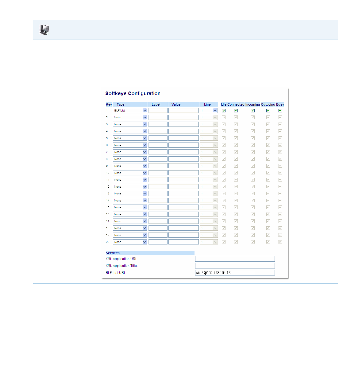
Operational Features
41-001343-02 REV04 – 05.2014 5-131
Aastra Web UI
1. Click on Operation->Softkeys and XML
or
Click on Operation->Programmable Keys
or
Click on Operation->Expansion Module <N>.
Depending on your phone-model, the key configuration screen displays. The 6755i Key Screen is shown as an example.
2. Select a softkey, programmable, or expansion module key to configure.
3. In the "Type" field, select "BLF" (Asterisk/sipXecs), "BLF/List" (BroadSoft BroadWorks).
4. For 8 and 11-Line LCD softkeys:
In the "Label" field, enter the name of the person who’s extension you are monitoring (if “Type” is BLF).
Note:
If BLF/List type is selected, no label value is required. The BroadWorks BLF List name is configured in the "BLF List URI" field instead.
5. In the "Value" field, enter a value to associate with the softkey or programmable key.
For example, for BLF, the value is the extension you want to monitor.
For BLF/List, the value is an identifier for the list of numbers you are monitoring.
6. Click Save Settings to save your changes.
7. In the "Line" field, select a line number that is actively registered to the appropriate SIP proxy you are using.

Operational Features
5-132 41-001343-02 REV04 – 05.2014
BLF Page Switch Feature
A new features enables the 6735i, 6737i, 6739i, 6755i, 6757i, 6757i CT, and 6867i model phones to automatically switch
the screen focus to a softkey page or M675i expansion module page that has an active Busy Lamp Field (BLF or BLF/List
key(s). Administrators can configure this feature using the “blf activity page switch” parameter.
If this parameter is set to “1”, the screen will switch to a softkey page or an M675i expansion module page if a monitored
extension transitions to a ringing (fast flashing) state. If this parameter is set to “2”, the screen will switch if a monitored
extension transitions to either a ringing (fast flashing) or a hold (slow flashing) state. Finally, if this parameter is set to “3”,
the screen will switch if a monitored extension transitions to either a ringing or hold state OR from an idle (off) state to
an “in call” (solid) state.
The following can be observed with this new feature:
•If there is a lot of activity on the monitored extensions, the page will be shown on the screen for at least 5 seconds
before switching again. When a user manually scrolls the pages by pressing the More key or the Function key (for the
page you want to display) on the M675i, no activity-triggered page flipping should occur for 5 seconds after the man-
ual switch.
•If the phone softkeys are hidden by an overlay screen, such as an XML UI object, a menu (e.g. the Services, Directory,
or Callers List menu), or if the phone is in an active call, the screen will not automatically switch focus to a softkey page
with BLF activity (it will however for an expansion module page).
•When the phone is in Idle mode, the menu switches to the page with the BLF key when there is an incoming call to the
monitored extension. The page is shown for 10 seconds if the call is answered. If the call is not answered by the BLF
extension, the BLF key page will be shown as long as ringing is ongoing.
•When the BLF key page is shown and there is another incoming call on another BLF key on the same page, the new
call is also shown on this BLF key.
•When the BLF key page is shown and there is another incoming call on another BLF key on another page, the switch
to the other page will be done after 10 seconds.
•When the BLF key page is shown and there are several more incoming calls on BLF keys, after 10 seconds the next
active BLF key will be shown in the key number order.
8. In the "BLF List URI" field, enter the name of the BLF list defined on the BroadSoft BroadWorks Busy Lamp field page for your particular user.
For example, sip:9@192.168.104.13.
Note:
The value of the BLF/List URI parameter must match the list name configured. Otherwise, no values display on the 6757i screen and the fea-
ture is disabled.
9. Click Save Settings to save your changes.
Note:
Applicable to the 6735i, 6737i, 6739i, 6755i, 6757i, 6757i CT, and 6867i IP Phones only.
Notes:
•To minimize the chance of a lot of switching between the Idle screen and the page(s) with BLF keys, it is recom-
mended to have the BLF keys with most frequent traffic on one page. If the expansion module has several BLF keys,
it is recommended to use an extra display panel unit.
•The IP phones (as well as the M675i Expansion Module) will automatically switch to the idle page (or the first page on
the M675i Expansion Module) if no BLF activity is detected by the phone.
Aastra Web UI

Operational Features
41-001343-02 REV04 – 05.2014 5-133
Configuring BLF Page Switch
Use the following procedures to configure the BLF page switch feature on the IP phone.
Configurable Display for Blank BLF/List Softkeys
When softkeys for the 6735i, 6737i, 6755i, 6757i, 6757i CT model phones and the M675i Expansion Module are configured
as BLF/List keys on the phone but there are not enough members in the BLF/List on the Broadsoft server side, then a series
of question marks are displayed on screen beside some of the softkeys.
Administrators can configure whether or not the series of question marks should be hidden using the “keys noname hid-
den” parameter. If this parameter is set to “1” (enabled) then the series of question marks will be hidden and nothing will
be shown on the screen beside the affected softkeys. If this parameter is set to “0” (disabled) then the series of question
marks will be displayed on the screen indicating blank BLF/List softkeys.
Configuring the Display for Blank BLF/List Softkeys
Use the following procedure to configure the display for blank BLF/List softkeys:
Ring Signal Type for BLF
There is a global parameter “play a ring splash” that controls whether or not a ring splash is played when there is an
incoming call on a Busy Lamp Field (BLF) monitored extension. For the 6739i, 6755i, 6757i, and 6757i CT IP phones, you
can configure the phone to play the ring splash when idle only or when idle and also in an active call state. For all other
phones, the ring splash can only be configured to play when in an idle state.
In addition to this global ring splash control, administrators can control the ring splash alert pattern on a per key basis.
Each type of key can have a different ring splash alerting pattern and volume. When the phone UI receives the event
update from the line manager for BLF transitions to ringing state, the ring splash value is checked to take the appropriate
action.
The following alerting patterns are available for all IP phones:
•0: Silence (ring splash off).
•1: Normal (same as current BLF ring splash).
•2: Normal delayed (After a delay of [x] seconds, the ring signal that is the same as the current BLF ring splash is played
[use the “ring splash delay” parameter to define the delay]).
•3: Periodic (similar to the normal ring signal that is used by the phone itself. The actual ring melody is based on the cur-
rent melody set for the line to which the BLF key is associated [use the “ring splash frequency” parameter to define
Configuration Files
To configure the BLF page switch on the IP phones using the configuration files, see Appendix A, the section, “BLF Page Switch” on pageA-192.
Note:
Applicable to the 6735i, 6737i, 6755i, 6757i, and 6757i CT IP Phones only.
Configuration Files
To configure the display for blank BLF/List softkeys on the IP phone using the configuration files, see Appendix A, the section, “Configurable Display
for Blank BLF/List Softkeys” on pageA-193.
Note:
The “play a ring splash” parameter is not dynamic. Changes to this parameter will take effect only after the phone has
been rebooted.

Operational Features
5-134 41-001343-02 REV04 – 05.2014
the frequency interval).

Operational Features
41-001343-02 REV04 – 05.2014 5-135
•4: Periodic delayed (same as Periodic but after a delay of [x] seconds, the ring signal that is used by the phone is played
[use the “ring splash frequency” parameter to define the frequency interval and the “ring splash delay” parameter to
define the delay]).
•5: Low volume (same as the current BLF ring splash but at a lower level to be less intrusive).
•6: Low volume delayed (after a delay of [x] seconds, the ring signal that is the same as the current BLF ring splash is
played at a lower level [use the “ring splash delay” parameter to define the delay]).
For the 6739i, 6755i, 6757i, and 6757i CT IP phones, the additional alerting patterns are available:
•7: The behavior is determined by the global parameter “play a ring splash”.
–If “play a ring splash” is defined as 0 then the feature is disabled.
–If “play a ring splash” is defined as 1 then the behavior is the same as Normal.
–If “play a ring splash” is defined as 2 the the behavior is the same as Normal but the ring splash plays when idle
and also during the active call state.
•8: In call delayed (same as Normal delayed but ring splash plays when idle and also during the active call state [use the
“ring splash delay” parameter to define the delay]).
•9: In call periodic (same as Periodic but ring splash plays when idle and also during the active call state [use the “ring
splash frequency” parameter to define the frequency interval).
•10: In call periodic delayed (same as Periodic delayed but ring splash plays when idle and also during the active call
state [use the “ring splash frequency” parameter to define the frequency interval and the “ring splash delay” param-
eter to define the delay]).
•11: In call low volume (same as Low volume but ring splash plays when idle and also during the active call state).
•12: In call low volume delayed (same as Low volume delayed but ring splash plays when idle and also during the active
call state [use the “ring splash delay” parameter to define the delay]).
The following parameters are available allowing administrators to set and pass the control of the ring splash to the key
(instead of the phone using the global “play a ring splash” parameter).
•“prgkeyN ring splash”
•“softkeyN ring splash”
•“topsoftkeyN ring splash”
•“expmodX KeyN ring splash”
•“ring splash delay” (applicable when the “...keyN ring splash” parameter is set to a “delayed” alerting pattern)
•“ring splash volume” (applicable when the “...keyN ring splash” parameter is set to a “low volume” alerting pattern)
•“ring splash frequency” (applicable when the “...keyN ring splash” parameter is set to a “periodic” alerting pattern)
The per key settings overwrite the global setting (“play a ring splash” parameter) on the phone. If the global parameter is
disabled, a ring splash can still be enabled on a key basis. If the global parameter is enabled, all keys will have a ring splash
unless the value “0” is configured explicitly for a key.
The following table details the ring splash behavior in the different call states/events when the feature is enabled for active
calls states. The behavior is consistent for all audio sources and audio mode configurations.
State Behavior
Idle Ring splash played through the speaker.
Active Call Ring splash played through the speaker.
Call Waiting Ring splash played through speaker.
Mid-Conference/Transfer Establishment Ring splash played through speaker.
Do Not Disturb (Idle/In Call) No ring splash played.
Hold Ring splash played through speaker.
Ringing - Outgoing Ring splash played through speaker.
Ringing - Incoming No ring splash played.

Operational Features
5-136 41-001343-02 REV04 – 05.2014
Considerations
The following considerations must be taken into account when using this feature:
•When a BLF softkey’s ring splash parameter is dynamically changed , the change will not take effect until the BLF tar-
get becomes idle.
•The playing of a ring splash will be postponed if it is not allowed to be played in the current state and will start playing
if the phone transitions to a state where the ring splash can be played. However, if the BLF target stops ringing before
the transition, the ring splash will not be played.
•The playing of a delayed ring splash will be postponed until the delay expires. However, if the BLF target stops ringing
before the delay expires, the ring splash will not be played.
•In scenarios where the BLF target goes into the ringing state while an initial in-call ring splash is playing or while a call
hold or call waiting reminder is playing, the secondary in-call ring splash will be played 500ms after the current event
has ended. The inverse is also true whereby call hold or call waiting reminders will be played 500ms after the BLF ring
splash, if they occur while a BLF ring splash is playing.
•In scenarios where multiple keys are configured for periodic ring splashes and multiple BLF targets are ringing, only
one periodic ring splash for one target will be played.
•While on an active call, if the “ring audibly enable” parameter is enabled and a call is incoming while a periodic ring
splash is playing, the periodic ring splash will stop allowing the incoming call’s ring tone to be played, and then
resume after the incoming call’s ring tone has ended.
Configuring Ring Splash Settings
Use the following parameters to configure the ring splashsettings:
Ring Signal Type for BLF/List
Administrators can also control whether or not a ring tone is played when there is an incoming call on a BLF/List-moni-
tored extension. Each BLF/List-monitored extension can be individually configured to play one of five different ring
tones (or to play none at all).
After configuring the BLF/List URI and BLF/List keys, you can enable ring tone playback on the BLF/List-monitored exten-
sions by defining the existing “play a ring splash” parameter as “1” in the respective configuration file.
Additionally, the following “ring splash” parameters can be used to control which specific ring tone is played (depend-
ing on the type of key for which BLF/List functionality is configured):
•softkeyN ring splash
•prgkeyN ring splash
•topsoftkeyN ring splash
•expmodX keyN ring splash
Initiating a direct call pickup of the BLF target No ring splash played.
Initiating a speed dial of the BLF target No ring splash played.
Configuration Files
To set the ring splash on a per key basis in the configuration files for BLF, see Appendix A, the sections “Ring Splash Settings” on pageA-193.
Note:
The “play a ring splash” parameter is not dynamic. Changes to this parameter will take effect only after the phone has
been rebooted.
State Behavior

Operational Features
41-001343-02 REV04 – 05.2014 5-137
Applicable values for the above parameters include:
•100 (Ring tone 1)
•101 (Ring tone 2)
•102 (Ring tone 3)
•103 (Ring tone 4)
•104 (Ring tone 5)
•105 (Silence)
Examples
To enable ring tone 3 playback for a BLF/List-monitored extension configured on a soft/prg/topsoft/expmodX “key1”, add
the following parameters in the respective configuration file:
For Softkeys
play a ring splash: 1
softkey1 type: list
softkey1 ring splash: 102
For Programmable Keys
play a ring splash: 1
prgkey1 type: list
prgkey1 ring splash: 102
For Top Softkeys
play a ring splash: 1
topsoftkey1 type: list
topsoftkey1 ring splash: 102
For Expansion Module Keys
play a ring splash: 1
expmod1 key1 type: list
expmod1 key1 ring splash: 102
Considerations
When using this feature the following must be taken into consideration:
•If there is an incoming call on a BLF/List-monitored extension, the corresponding ring tone will play only if all of the reg-
ular lines are in an idle or hold state and both paging and conf/xfer is not active.
•The BLF/List-related ring tone will stop playing if a regular line starts dialing, starts ringing, is unheld, or if paging is acti-
vated. The BLF/List-related ring tone will resume when the phone is in an idle state and paging is not active.
•If multiple BLF/List-monitored extensions are ringing simultaneously, they are placed in a queue based on the ringing
start time and priority is given to the extension that rang first. For example, if BLF/List is configured for extension 1,
extension 2, and extension 3, and all three receive incoming calls in sequence, the phone will play the ring tone for
extension 1. If ringing stops for extension1, ringing will begin for extension 2, and so on.
•Call waiting tone playback behavior for BLF/List-monitored extensions is based on the same rules as regular lines, but
the call waiting tone for BLF/List-monitored extensions will also be played/stopped when paging is activated/deacti-
vated.
Note:
Ring tones are based on the current ring tone set configured on the IP phone.

Operational Features
5-138 41-001343-02 REV04 – 05.2014
Configuring Ring Splash Settings
Use the following parameters to configure the ring splashsettings:
BLF Subscription Period
On the IP phones, you can set the time period, in seconds, that the IP phone re-subscribes the BLF subscription service.
In the configuration files, enter the following parameter with a valid value to set the BLF subscription period:
sip blf subscription period: <value in seconds>
The minimum value for this parameter is 120 seconds (2 minutes) and the maximum is 2147483647 seconds. The default
is 3600 (1 hour). The phone resubscribes to the BLF subscription service before the defined subscription period ends.
You can configure this feature using the configuration files or the Aastra Web UI.
Configuring BLF Subscription Period
Use the following procedures to configure the BLF subscription period on the IP phone.
Configuration Files
To set the ring splash on a per key basis in the configuration files for BLF, see Appendix A, the sections “Ring Splash Settings” on pageA-193.
Note:
The “sip blf subscription period” parameter is not applicable to BLF/List subscriptions.
Configuration Files
To configure the BLF subscription period on the IP phones using the configuration files, see Appendix A, the section, “Advanced SIP Settings” on
pageA-82.
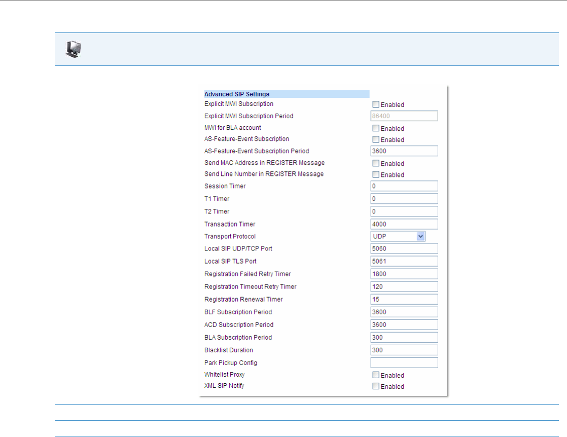
Operational Features
41-001343-02 REV04 – 05.2014 5-139
BLF/Xfer and Speeddial/Xfer Keys
The IP Phones have a transfer (Xfer) enhancement feature you can use with the BLF and Speeddial keys - BLF/Xfer and
Speeddial/Xfer.
The BLF key allows one or more extensions to be monitored, and once there is any state change with those extensions, the
key shows the status of the monitored lines. The Xfer key allows a call to be transferred to other recipients blindly or con-
sultatively.
The Speeddial key allows a number to be dialed quickly by pressing one key configured for speeddialing. After answering
a call, the recipient can transfer the call to an extension by:
Aastra Web UI
1. Click on Advanced Settings->Global SIP->Advanced SIP Settings.
2. Enter a value, in seconds, from 120 to 2147483647 in the "BLF Subscription Period" field.
3. Click Save Settings to save your changes.
1. Pressing Xfer key.
2. Entering the number of the extension or pressing Speeddial or BLF key.
3. Pressing Xfer key again

Operational Features
5-140 41-001343-02 REV04 – 05.2014
The BLF and Speeddial transfer enhancement feature provides a simpler way of transferring calls using the keys called
BLF/Xfer and Speeddial/Xfer. The BLF/Xfer key combines the BLF and Xfer key's functionality together allowing the
user to transfer calls or use BLF with one key. Similarly, the Speeddial/Xfer key combines the Speeddial key and Xfer
key's functionality together allowing the user to press one key to speeddial and transfer calls.
BLF/Xfer Key Requirements and Functionality
•BLF/Xfer and BLF
A BLF/Xfer key can be configured for subscribing to an extension and monitor the status of the extension, similar to
the BLF key functionality. Changes of the state of the monitored extension are indicated by a LED / Icon.
•BLF/Xfer and Blind Transfer Calls
When the focused line is in the “Connected” state, pressing the BLF/Xfer key transfers the call to the extension uncon-
ditionally, disregarding the status of the monitored extension.
If transferring a call to an extension fails, a message “Transfer Failed” displays on the phone, and you can reconnect the
call (get the call back) by pressing the line key again.
•BLF/Xfer and Call forward
When the focused line is in the “Ringing” state, pressing the BLF/Xfer key forwards the call to the extension uncondi-
tionally, disregarding the status of the monitored extension.
•BLF/Xfer and Speeddial
When the focused line and the monitored extension are idle, pressing the BLF/Xfer key causes the phone to go off-
hook and dial the number of the extension.
Speeddial/Xfer Key Requirements and Functionality
The Speeddial/Xfer key has the following capabilities:
•Speeddial/Xfer and Speeddial
When the phone is in the “Idle” state, pressing the Speeddial/Xfer key causes the phone to go offhook and dial the
predefined extension.
•Speeddial/Xfer and Blind Transfer
When the phone is connected to a call, pressing the Speeddial/Xfer key blind transfers the call to the predefined tar-
get.
If transferring a call fails, a message “Transfer Failed” displays, and you can reconnect the call (get the call back) by
pressing the line key again.
•Speeddial/Xfer and Call Forward
When the phone is in the “Ringing” state, pressing the Speeddial/Xfer key forwards the call to the predefined exten-
sion.
Note:
It is recommended that you enable the “switch focus to ringing” parameter when using the BLF and Speeddial Trans-
fer key feature. For more information about this parameter, see “Switch Focus to Ringing Line” on page5-64.
Note:
On the 6739i, you can configure a BLF./Xfer and Speeddial/Xfer softkeys using the IP Phone UI also. For more informa-
tion, see the Aastra Model 6739i IP Phone User Guide.

Operational Features
41-001343-02 REV04 – 05.2014 5-141
Configuring the BLF/Xfer Key and the Speeddial/Xfer Key Using the Configuration Files
You use the following parameters in the configuration files to configure the BLF/Xfer key and/or Speeddial/Xfer key on the
IP Phone.
Examples:
softkey1 type: speeddialxfer
softkey1 label: BX7801
softkey1 value: 7801
softkey1 line: 1
softkey1 states: idle connected incoming outgoing busy
prgkey1 type: blfxfer
prgkey1 value: 35
prgkey1 line: 1
Refer to the following in Appendix A to configure a BLF/Xfer and Speeddial/Xfer key on the IP phone using the configura-
tion files.
Softkey Parameters Programmable Key Parameters Expansion Module Parameters
softkeyN type
softkeyN label
softkeyN value
softkeyN line
softkeyN states
prgkeyN type
prgkeyN value
prgkeyN line
expmodN keyN type
expmodN keyN label
expmodN keyN value
expmodN keyN line
Top Softkey Parameters
topsoftkeyN type
topsoftkeyN label
topsoftkeyN value
topsoftkeyN line
Configuration Files
To set a BLF/Xfer and Speeddial/Xfer key using the configuration files, see Appendix A, “Softkey/Programmable Key/Keypad Key/Feature Key/Expan-
sion Module Key/Hard Key Parameters” on pageA-156.
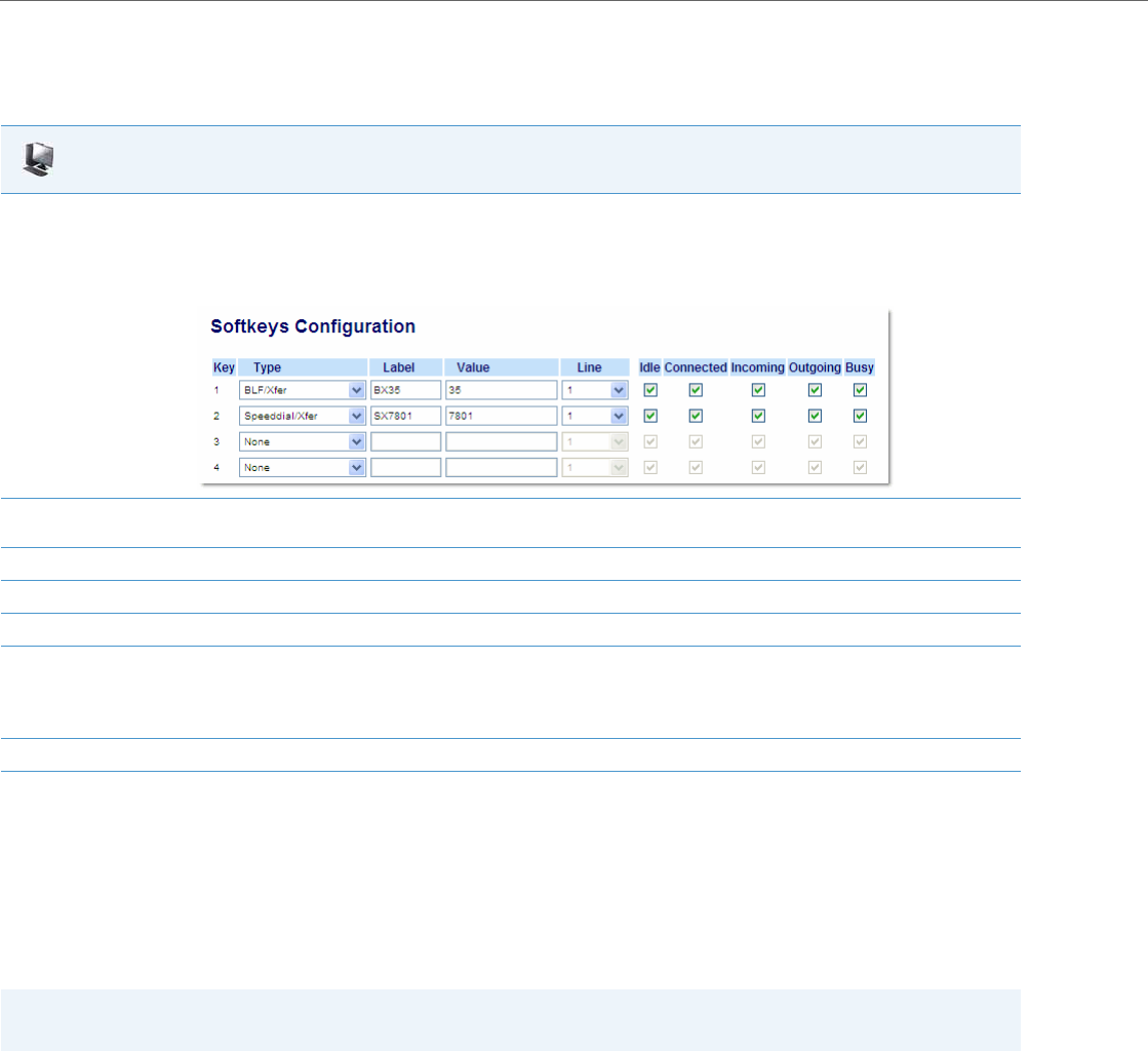
Operational Features
5-142 41-001343-02 REV04 – 05.2014
Configuring the BLF/Xfer Key and the Speeddial/Xfer Key Using the Aastra Web UI
You configure the BLF/Xfer key and/or the Speeddial/Xfer Key on the IP phone similar to configuring a BLF key or Speed-
dial key using the Aastra Web UI. Use the following procedure to configure BLF/Xfer and/or Speeddial/Xfer.
Speeddial/Conference Key
The IP Phones allow you to configure a softkey/programmable key/expansion module key to be used as a Speeddial
Conference key (Speeddial/Conf key) while remaining in the current call. This key allows a user on a call, to conference
another party at a pre-defined number while remaining in the conference call.
For example, while on an active call, a user can use the Speeddial/Conf key to dial a recording service and have the result-
ing conference recorded.
How it Works
If you configure a softkey/programmable key/expansion module as a Speeddial/Conf key, and you press this key while
on an active call, the focused line changes to the dialing line. A Cancel softkey displays on the phone (only those phones
that have LCDs larger then 3 lines), allowing you to abort the conference speeddial if required. The message "Ringing..."
displays below the number when the far end is ringing. The message "Conf. Unavailable" briefly displays when a confer-
ence is already in progress or when the CT handset is in use. The active call is not put on hold when the speeddial
number is dialed.
Aastra Web UI
1. Click on Operation->Softkeys and XML.
or
Click on Operation->Programmable Keys.
or
Click on Operation->Expansion Keys.
2. Choose a key that you want to assign the BLF/Xfer key or a Speeddial/Xfer key to, and select BLF/Xfer or Speeddial/Xfer from the “Type”
field.
3. In the “Label” field, enter a key label to assign to the BLF/Xfer key (for example, “BX35”).
4. In the “Value” field, enter the monitored extension (for example, “35”).
5. In the “Line” field, select the line for which you want to use the key functionality.
6. Select the state(s) (idle, connected, incoming, outgoing, busy) for which you want to use on the key.
Note:
States are not applicable to programmable keys.
7. Click Save Settings to save your changes.
Note:
If currently in a conference, the Speeddial/Conf key is disabled on the active call.

Operational Features
41-001343-02 REV04 – 05.2014 5-143
Limitations for Speeddial/Conference Key
The following are limitations for the Speeddial/Conference key:
•The CT handsets are not supported.
•The feature is not compatible with centralized conferencing.
The softkey/programmable key is called "Speeddial/Conf" in the Web UI drop down list. In the configuration file, use
"speeddialconf" as the softkey type.
Configuring the Speeddial/Conf Key Using the Configuration Files
To configure the Speeddial/Conf key using the configuration files, you enter “speeddialconf” for the key type. The follow-
ing parameters are examples you can use to configure the Speeddial/Conf key:
softkey1 type: speeddialconf
softkey1 label: Sales
softkey1 value: 5645
softkey1 line: 3
Note:
On the 6739i, you can configure a Speeddial/Conf softkey using the IP Phone UI also. For more information, see the
Aastra Model 6739i IP Phone User Guide.
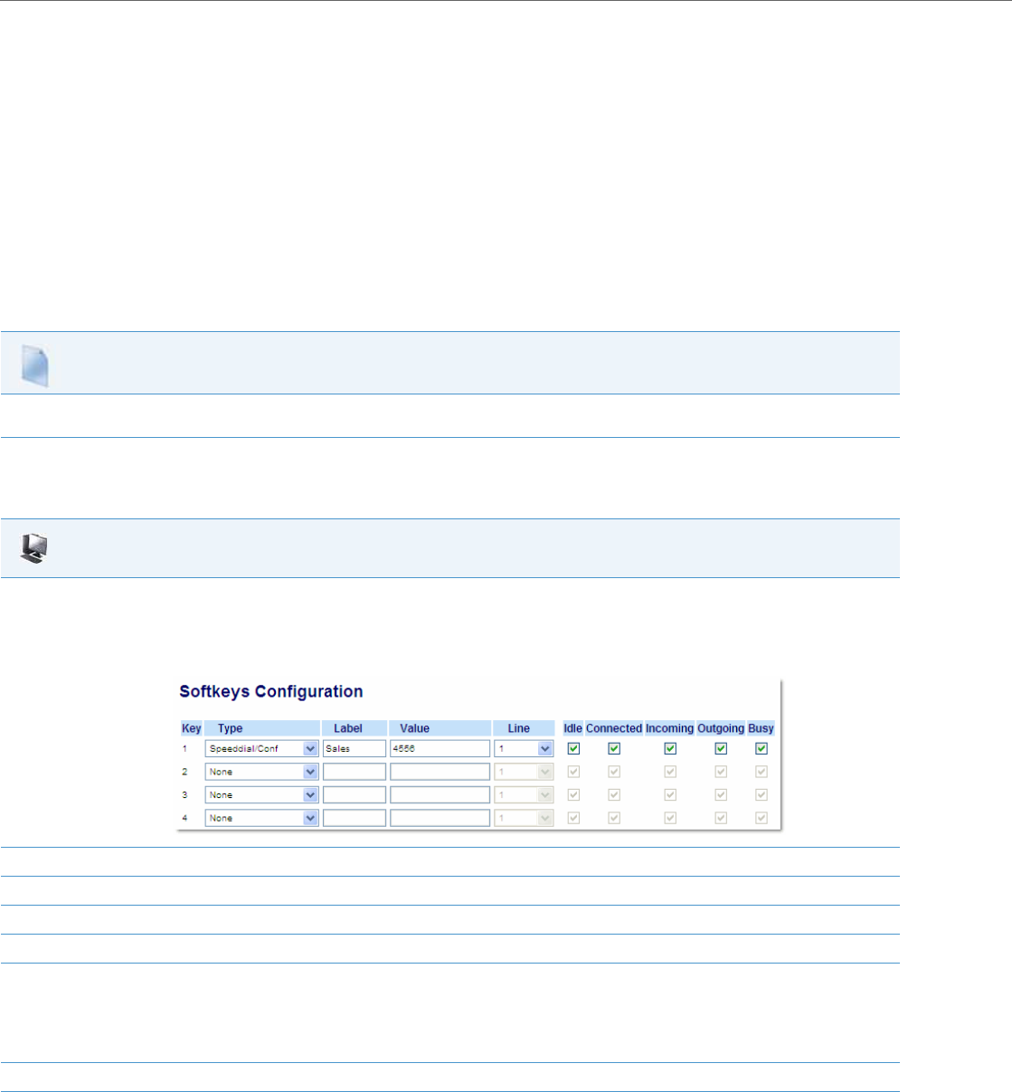
Operational Features
5-144 41-001343-02 REV04 – 05.2014
topsoftkey1 type: speeddialconf
topsoftkey1 label: Sales
topsoftkey1 value: 5645
topsoftkey1 line: 3
prgkey1 type: speeddialconf
prgkey1 value: 5645
prgkey1 line: 1
expmod1 key1 type: speeddialconf
expmod1 key1 label: Sales
expmod1 key1 value: 5645
expmod1 key1 line: 3
Refer to the following in Appendix A to configure a Speeddial/Conf key on the IP phone using the configuration files.
Configuring the Speeddial/Conf Key Using the Aastra Web UI
Use the following procedure to configure the Speeddial/Conf Key using the Aastra Web UI.
Configuration Files
To set a Speeddial/Conf key using the configuration files, see Appendix A, “Softkey/Programmable Key/Keypad Key/Feature Key/Expansion Module
Key/Hard Key Parameters” on pageA-156.
Aastra Web UI
1. Click on Operation->Softkeys and XML.
or
Click on Operation->Programmable Keys.
or
Click on Operation->Expansion Module Keys.
2. In the “Type” field, select Speeddial/Conf from the list of options.
3. In the “Label” field, enter a key label to assign to the Speeddial/Conf key (for example, “Sales”).
4. In the “Value” field, enter the number that the phone dials when the Speeddial/Conf key is pressed (for example, “4556”).
5. In the “Line” field, select the line for which you want to use the key functionality.
6. For phones with softkeys:
In the States field, select the state(s) (idle, connected, incoming, outgoing, busy) for which you want to use on the key.
Note:
States are not applicable to programmable keys (9143i, 6730i, 6731i, 6735i, 6753i, 6755i, 6863i, 6865i).
7. Click Save Settings to save your changes.

Operational Features
41-001343-02 REV04 – 05.2014 5-145
Speeddial/MWI Key
Multiple voicemail registration is supported on the IP phones. This feature can be useful in scenarios where a user needs to
monitor the voicemail accounts of his/her team members or an assistant requires access to his/her manager’s voicemail
messages.
By configuring a softkey, programmable key, or expansion module softkey as Speeddial/MWI and defining call and voice-
mail URIs, users can monitor and listen to pending messages on multiple voicemail accounts. When new messages are
pending on a monitored voicemail account the corresponding Speeddial/MWI key’s LED will blink and the UI (for softkeys)
will display an envelope icon and the number of pending messages beside the defined label.
When a user presses the softkey, the phone will send an INVITE to the configured call URI whereby the user will be able to
listen to the new messages.
Users can configure the Speeddial/MWI key through the Aastra Web UI while Administrators can configure the key
through the Aastra Web UI as well as the configuration files.
Configuring the Speeddial/MWI Key Using the Configuration Files
To configure the Speeddial/MWI key using the configuration files, you must enter “speeddialmwi” for the key type. For the
label, enter a key label to assign to the Speeddial/MWI key (e.g. Peter). For the value, enter in the call URI and voicemail URI
separated by a semi-colon, as per the following syntax: [call URI];[voicemail URI]. For example:
+33123456,,,3456#0000#@domain;sip:voicemail_peter@domain
For the line, enter the line for which you want to use the key functionality (e.g. 1 through 9).
The following parameters are examples you can use to configure the Speeddial/MWI key using the configuration files:
For Softkeys
softkey1 type: speeddialmwi
softkey1 label: Peter
softkey1 value: +33123456,,,3456#0000#@domain;sip:voicemail_peter@domain
softkey1 line: 3
For Top Softkeys
topsoftkey1 type: speeddialmwi
topsoftkey1 label: Peter
topsoftkey1 value:
+33123456,,,3456#0000#@domain;sip:voicemail_peter@domain
topsoftkey1 line: 3
For Programmable Keys
prgkey1 type: speeddialmwi
prgkey1 value: +33123456,,,3456#0000#@domain;sip:voicemail_peter@domain
prgkey1 line: 3
Note:
This feature is not supported for the 6735i, 6737i, 6863i, 6865i, and 6867i in Release 3.3.1 SP3.
Note:
For the 6739i IP phone, the Speeddial/MWI key can be configured directly using the IP phone’s UI.
Notes:
•As the example above illustrates, pauses and DTMF are supported for the call URI.
•Ensure that no spaces are added between the call URI and the voicemail URI when defining the key value.
•If only one URI is provided, the value will be used for the voicemail URI and the call URI will be left as undefined.

Operational Features
5-146 41-001343-02 REV04 – 05.2014
For Expansion Module Softkeys
expmod1 key1 type: speeddialmwi
expmod1 key1 label: Peter
expmod1 key1 value: +33123456,,,3456#0000#@domain;sip:voicemail_peter@domain
expmod1 key1 line: 3
Refer to the following in Appendix A to configure a Speeddial/MWI key on the IP phone using the configuration files.
Configuration Files
To set a Speeddial/Conf key using the configuration files, see Appendix A, “Softkey/Programmable Key/Keypad Key/Feature Key/Expansion Module
Key/Hard Key Parameters” on pageA-156.
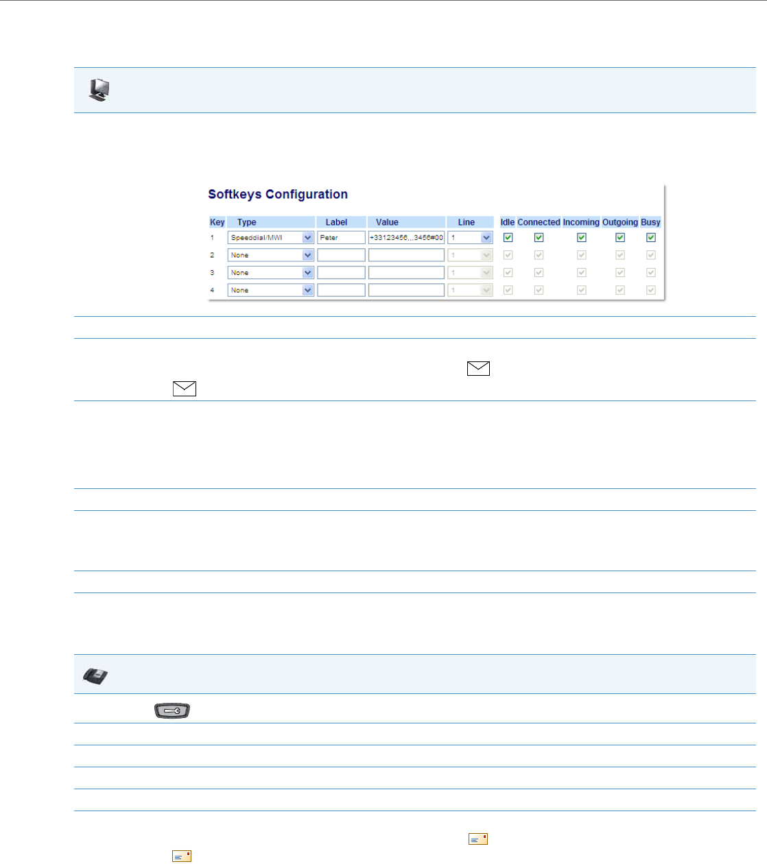
Operational Features
41-001343-02 REV04 – 05.2014 5-147
Configuring a Speeddial/MWI Key Using the Aastra Web UI
Use the following procedure to configure a Speeddial/MWI key using the Aastra Web UI:
Configuring a Speeddial/MWI Key Using the IP Phone UI (6739i only)
Use the following procedure to configure a Speeddial/MWI key using the 6739i IP phone’s UI:
Aastra Web UI
1. Click on Operation->Softkeys and XML.
or
Click on Operation->Programmable Keys.
or
Click on Operation->Expansion Module Keys.
2. In the “Type” field, select Speeddial/MWI from the list of options.
3. If applicable, in the “Label” field, enter a key label to assign to the Speeddial/MWI key.
When messages are pending, the IP phone UI will display an envelope icon , the number of pending messages, and then the defined
label (e.g. 3 Peter).
4. In the “Value” field, enter in the call URI and voicemail URI separated by a semi-colon, as per the following syntax: [call URI];[voicemail URI].
For example, +33123456,,,3456#0000#@domain;sip:voicemail_peter@domain
Notes:
As the example above illustrates, pauses and DTMF are supported for the call URI.
Ensure that no spaces are added between the call URI and the voicemail URI when defining the key value.
If only one URI is provided, the value will be used for the voicemail URI and the call URI will be left as undefined.
5. In the “Line” field, select the line for which you want to use the key functionality.
6. For phones with softkeys:
In the “States” field, select the state(s) (idle, connected, incoming, outgoing, busy) for which you want to use on the key.
Note:
States are not applicable to programmable keys.
7. Click Save Settings to save your settings.
IP Phone UI
1. Press on the phone to enter the Options menu.
2. Select Softkeys. By default, all of the softkeys that display are configured as “None”.
3. Press a <None> key. A softkey configuration screen displays.
4. In the “Type” field, press the <None> key. A screen displays with softkey keys.
5. Press the <Speeddial/MWI> function key to apply to the softkey.
1. In the “Label” field, enter a key label to assign to the Speeddial/MWI key.
When messages are pending, the IP phone UI will display an envelope icon , the number of pending messages, and then the defined
label (e.g. 3 Peter).
Operational Features
5-148 41-001343-02 REV04 – 05.2014
2. In the “Value” field, enter in the call URI and voicemail URI separated by a semi-colon, as per the following syntax: [call URI];[voicemail URI].
For example, +33123456,,,3456#0000#@domain;sip:voicemail_peter@domain
Notes:
As the example above illustrates, pauses and DTMF are supported for the call URI.
Ensure that no spaces are added between the call URI and the voicemail URI when defining the key value.
If only one URI is provided, the value will be used for the voicemail URI and the call URI will be left as undefined.
3. In the “Line” field, press the or to select a line for which to apply to the softkey. Valid values are 1 through 9.
4. Press <Save> to save the softkey. The softkey applies to your phone immediately and displays on your idle screen.
5. Press the to return to the previous menu or press the key to return to the idle screen.
IP Phone UI

Operational Features
41-001343-02 REV04 – 05.2014 5-149
Automatic Call Distribution (ACD) (for Sylantro Servers)
The IP phones support an Automatic Call Distribution (ACD) feature for Sylantro servers. The ACD feature allows the
Sylantro server to distribute calls from a queue to registered IP phone users (agents).
To use the ACD feature on an IP phone, the administrator must first configure an ACD softkey or programmable key. When
an IP phone user wants to subscribe to a queue (in order to receive incoming calls), the user presses the ACD key. The IP
phone UI prompts the user to log in.
When the IP phone user is ready to receive calls from the server, the user logs into a queue. Depending on the server con-
figuration, the IP phone is either in an “unavailable” or “available” state. If the phone is set to “available” then the server
begins to distribute calls to this phone immediately. If the phone is set to unavailable, then server waits until the IP phone
user manually changes the phone status to “available” (using the IP phone UI) before distributing calls.
Whenever the IP phone user answers a call, or misses a call, the server automatically changes the phone’s status to unavail-
able. The server updates it database with this new information and no longer distributes calls to this phone. The IP phone
will remain in this state until:
•the IP phone user makes himself “available” again.
•the ACD auto-availability timer expires. This occurs only if the administrator has configured an ACD auto-availability
timer as described in “ACD Auto-Available Timer” on page5-147.
The IP phone user can also choose to manually change the phone status to unavailable, using the IP Phone UI.
ACD Auto-Available Timer
Whenever the IP phone user answers a call, or misses a call, the server automatically changes the phone’s status to unavail-
able. The administrator can control how long the IP phone remains in the unavailable state by configuring an auto-availa-
ble timer. When the timer expires, the IP phone status is automatically changed to available. The default setting for the
timer is 60 seconds.
You use the following parameters to configure an ACD Auto-Available Timer in the configuration files:
•acd auto available
•acd auto available timer
Configuring an Automatic Call Distribution (ACD) Key
You can configure an ACD key on softkeys, programmable keys, and extension module keys.
The following table illustrates examples of configuring an ACD key on the phone.
Note:
It is recommended you configure no more than a single ACD softkey or programmable key per IP phone.
Note:
On the 6739i, you can configure an ACD softkey using the IP Phone UI also. For more information, see the Aastra Model
6739i IP Phone User Guide.
Softkey Examples Top Softkey Examples Programmable Key Exam-
ples Extension Module Examples
softkey1 type: acd
softkey1 label: sales
softkey1 line: 1
softkey1 states: idle
topsoftkey1 type: acd
topsoftkey1 label: sales
topsoftkey1 line: 1
topsoftkey1 states: idle
prgkey1 type: acd
prgkey1 line: 1
expmod1 key1 type: acd
expmod1 key1 label: sales
expmod1 key 1 line: 1
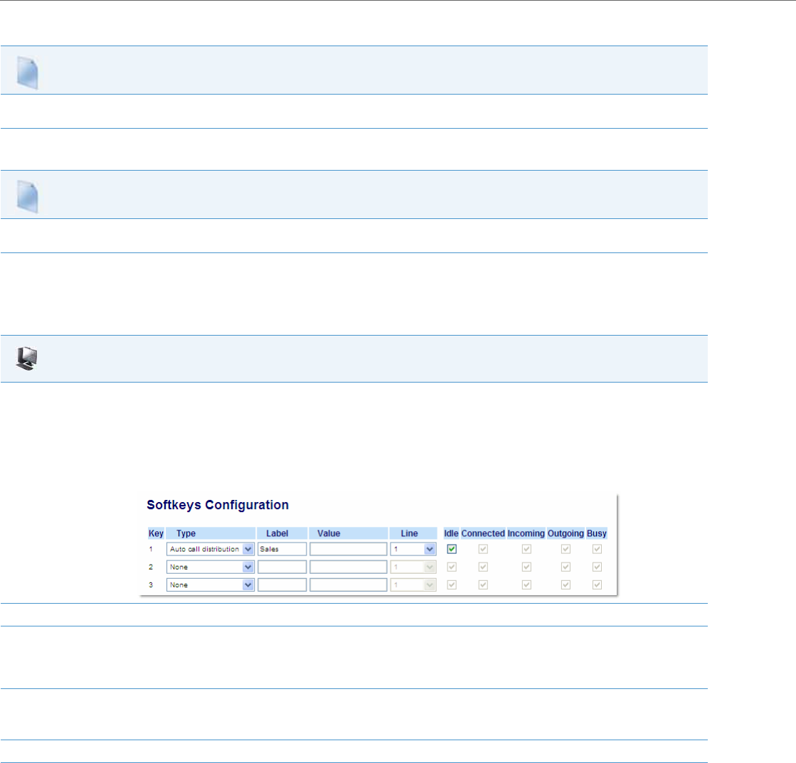
Operational Features
5-150 41-001343-02 REV04 – 05.2014
Use the following procedures to configure an ACD key on the IP phone.
Configuring the ACD Auto-Available Timer
Configuring an ACD Key Using the Aastra Web UI
Use the following procedure to configure an ACD softkey, programmable key, or expansion module key using the Aastra
Web UI. This procedure uses the 6757i IP phone as an example.
Configuration Files
To configure an ACD key using the configuration files, see Appendix A, the section, “Softkey/Programmable Key/Keypad Key/Feature Key/Expansion
Module Key/Hard Key Parameters” on pageA-156.
Configuration Files
To configure the ACD Auto-Available Timer using the configuration files, see Appendix A, the section, “ACD Auto-Available Timer Settings” on pageA-
151.
Aastra Web UI
1. Click on Operation->Softkeys and XML
or
Click on Operation->Programmable Keys
or
Click on Operation->Expansion Module <N>.
Depending on your phone-model, the key configuration screen displays. The 6755i Key Screen is shown as an example.
2. In the “Type” field, select Auto Call Distribution.
3. In the “Label” field, specify a name for this ACD softkey. The Label helps identify which queue you are subscribing to when you login. (This
field does not apply to the programmable keys on the 6730i, 6731i, 6735i, 6753i, 6755i and 9143i.)
For example: Sales
4. In the “Line” field, select the line which the IP phone uses to subscribe to the queue.
For example: Line 1
5. Click Save Settings to save your changes.
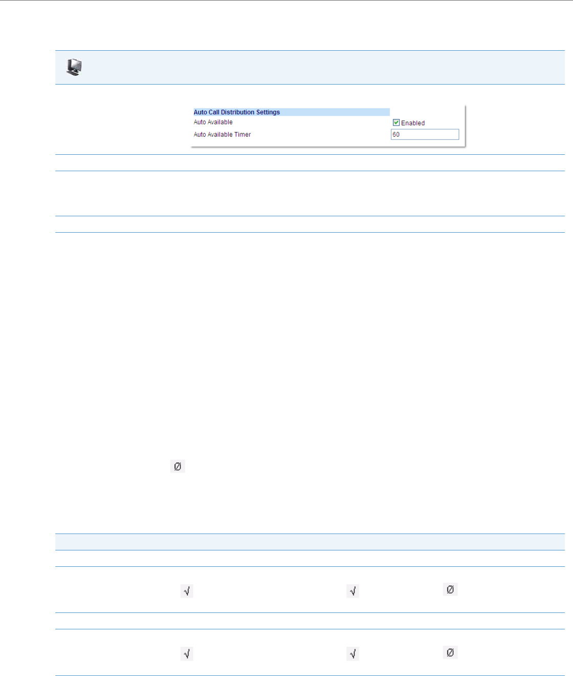
Operational Features
41-001343-02 REV04 – 05.2014 5-151
Configuring the ACD Auto-Available Timer Using the Aastra Web UI
Use the following procedure to configure an ACD auto-available timer using the Aastra Web UI.
Using the ACD Feature on your IP Phone
The ACD feature allows you to login to a phone queue in order to receive distributed calls on your IP phone. To login to a
phone queue, your system administrator must preconfigure an ACD softkey or programmable key on your Aastra IP
phone.
For models 8 and 11-Line LCD phones, the ACD softkey is labeled according to your network requirements. Check with
your administrator to verify the label assigned to the ACD softkey on your IP phone. The label usually describes which
phone queue you are accessing when you press the ACD softkey.
For example, suppose the administrator wants to configure an ACD softkey to allow an IP phone user to log into the Cus-
tomer Support phone queue. The administrator assigns the label “Support” to the softkey, so it is easily recognizable to
the IP phone user. When the IP phone user wants to subscribe to the Customer Support queue, the user presses the Sup-
port key and can log in.
Once logged in to the queue, you can make yourself “available” or “unavailable” to take calls by pressing the Availa-
ble/Unavailable key on the phone UI. The server monitors your IP phone status. When you set the IP phone to “available,”
the server begins distributing calls to your phone. When you set the IP phone to “unavailable,” the server temporarily stops
distributing calls to your phone.
The icon that appears next to the ACD softkey or programmable key on the IP Phone UI reflects your current status. In the
example shown below, the icon shows the current status of this IP phone user as “logged off.”
This icon changes when you log on to the phone queue and are available to take calls. The icon changes again when you
are busy with an active call.
The table below describes the meaning of the LED, and each icon, as they may appear on your IP phone:
Aastra Web UI
1. Click on Basic Settings->Preferences->Auto Call Distribution Settings.
2. In the “Auto Available” check-box, click Enabled.
3. In the “Auto Available Timer” field, specify the length of time (in seconds) before the IP phone state is automatically reset to “available.”
Valid values are 0 to 120 seconds. Default is 60.
For example: 60
4. Click Save Settings to save your changes.
Phone Model Status: Logged In and Available Status: Unavailable Logged Out
9143i Solid Red LED Blinking red LED No LED
9480i, 9480i CT Solid Red LED
icon
Blinking Red LED
Blinking icon
No LED
icon
6730i, 6731i, 6753i Solid Red LED Blinking red LED No LED
6735i, 6737i, 6755i, 6757i, 6757i
CT Solid Red LED
icon
Blinking Red LED
Blinking icon
No LED
icon

Operational Features
5-152 41-001343-02 REV04 – 05.2014
Logging In to a Phone Queue
Use the following procedure to log into a phone queue from your Aastra IP phone.
ACD Subscription Period
On the IP phones, you can set the time period, in seconds, that the IP phone resubscribes the ACD subscription service
after a software/firmware upgrade or after a reboot of the IP phone.
In the configuration files, you enter the following parameter with a valid value to set the ACD subscription period:
sip acd subscription period: <value in seconds>
The minimum value for this 120 seconds (2 minutes).
The default is 3600 (1 hour).
Setting this parameter to a value lower than 3600 allows the configured ACD feature to become active more quickly after
a software/firmware upgrade or after a reboot of the IP phone. If you enter a value lower than 120 for this parameter, the
default value (3600) will be used by the IP phone.
You can configure this feature using the configuration files or the Aastra Web UI.
Configuring ACD Subscription Period
Use the following procedures to configure the ACD subscription period on the IP phone.
IP Phone UI
1. Press the ACD key on your IP phone.
Note:
Check with your administrator to verify the label assigned to the ACD softkey on your IP phone.
The login screen appears. In this example, the ACD softkey accesses the Customer Support phone queue and is labelled “Support.”
2. Press the Log In softkey.
You are logged into the phone queue. Once you log in, examine the IP Phone UI, and note the following information:
•If your IP phone status is set to “available” then the server will begin to distribute phone calls from this queue to your IP phone.
•If your IP phone status remains “unavailable” after you log in, then you must manually change the state to “available” in order to start
receiving calls.
•To temporarily stop receiving calls, you can switch the IP phone status to “unavailable.”
While you are on a call (or miss a call that has been distributed to your IP phone), your IP phone status automatically switches to “unavailable.”
Your IP phone remains in the unavailable state until one of the following things occur:
•You use the IP Phone UI to manually switch the IP phone state back to available, or
•The availability “timer” for your IP phone expires. This only occurs if your administrator has configured an auto-availability timer on your
IP phone.
3. To Log out of the queue, select Log Out. The server no longer distributes phone calls to your IP phone.
Configuration Files
To configure the ACD subscription period on the IP phones using the configuration files, see Appendix A, the section, “Advanced SIP Settings” on
pageA-82.
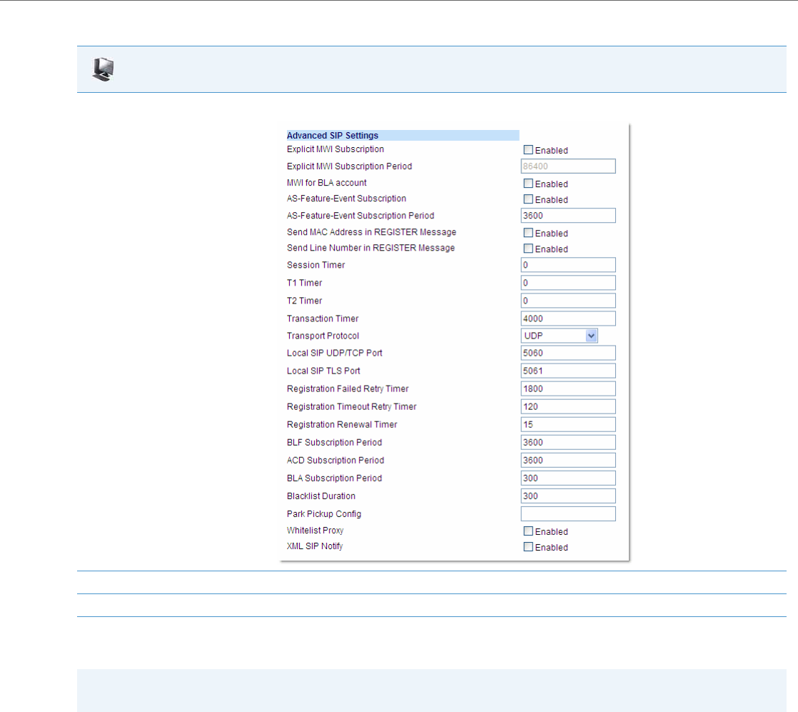
Operational Features
41-001343-02 REV04 – 05.2014 5-153
Directed Call Pickup/Group Call Pickup
Aastra IP phones and any attached Expansion Modules support the Directed Call Pickup (DCP) and Group Call Pickup
(GCP) features.
The Directed Call Pickup/Group Call Pickup feature allows you to intercept - or pickup - a call on a monitored extension. An
Administrator or User can configure this feature using the Aastra Web UI to create a DCP or GCP softkey on the IP phone.
When you configure a DCP softkey, you specify the extension that you want to monitor. Then, when the monitored exten-
sion receives a call, you press the DCP softkey to “pickup” (intercept) it. If the monitored extension receives multiple
incoming calls simultaneously, the IP Phone UI displays a list of incoming calls. You select a call from this list, and are con-
nected to the call.
Aastra Web UI
1. Click on Advanced Settings->Global SIP->Advanced SIP Settings.
2. Enter a value, in seconds, from 120 (2 min) to 3600 (1 hour) in the "ACD Subscription Period" field.
3. Click Save Settings to save your changes.
Note:
This feature is not supported for the 6735i, 6737i, 6863i, 6865i, and 6867i in Release 3.3.1 SP3.
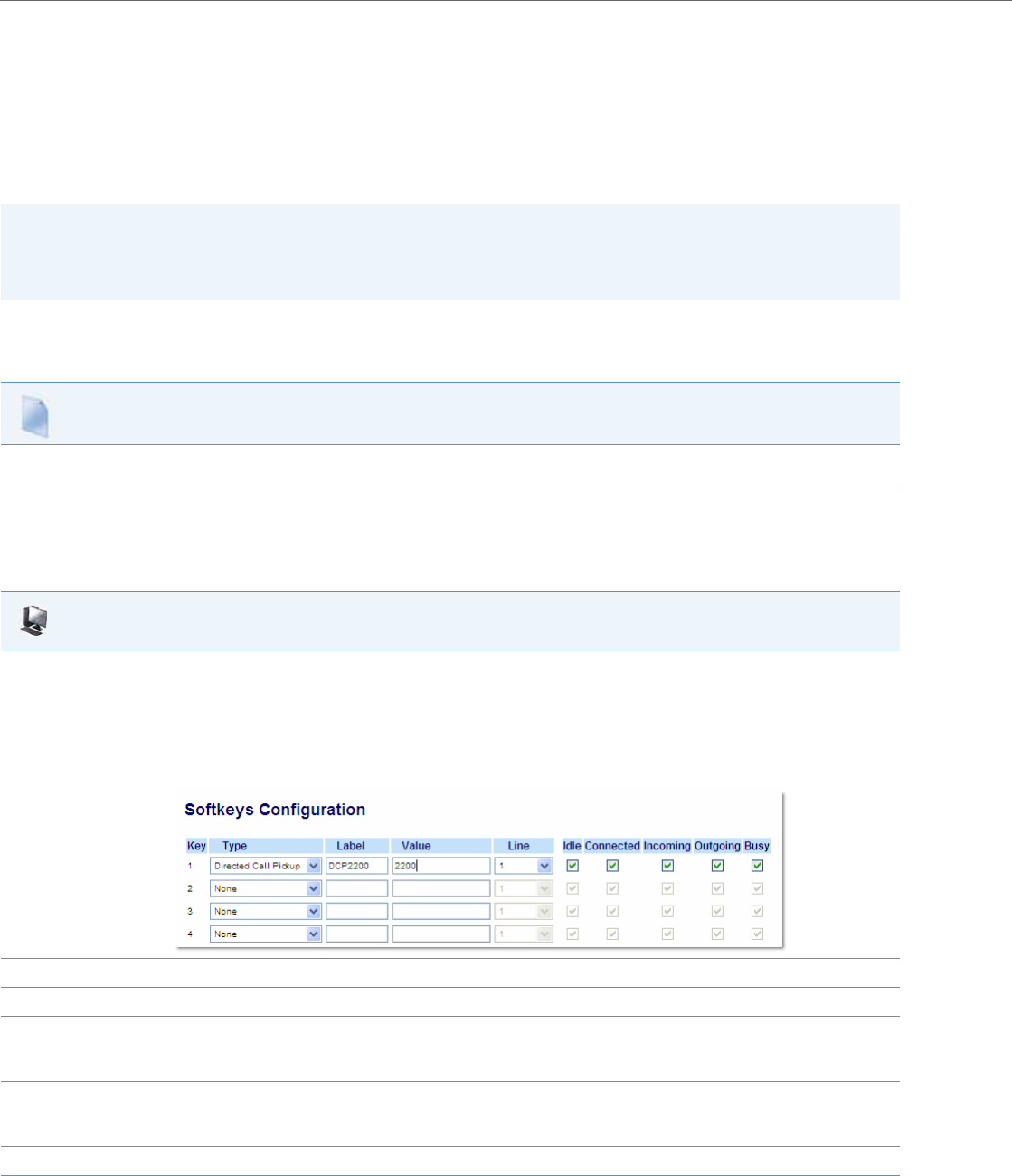
Operational Features
5-154 41-001343-02 REV04 – 05.2014
When you configure a GCP softkey, you specify the ring group that you want to monitor for incoming calls. For example,
suppose an Operator configures a GCP softkey to monitor incoming calls for a specific ring group (extensions 2200-
2210). When an incoming call is received on any of these extensions, the Operator presses the GCP softkey and is con-
nected to the call. If multiple incoming calls are received simultaneously, the Operator does the following actions:
•Presses the GCP softkey. The Operator Phone UI displays the current list of incoming calls (see below).
•Selects an extension to “pickup” first.
•Presses the Pickup softkey. The Operator is connected to the incoming call.
Configuring DCP/GCP Using the Configuration Files
Use the following procedures to configure DCP/GCP using the configuration files.
Configuring Directed Call Pickup (DCP) Using the Aastra Web UI
Use the following procedure to configure Directed Call Pickup using the Aastra Web UI. This procedure uses the 6755i IP
Phone as an example.
Notes:
•DCP/GCP feature availability is dependant on your call manager.
•On the 6739i, you can configure DCP/GCP softkey using the IP Phone UI also. For more information, see the Aastra
Model 6739i IP Phone User Guide.
Configuration Files
To set DCP/GCP in the configuration files, see Appendix A, the section, “Softkey/Programmable Key/Keypad Key/Feature Key/Expansion Module
Key/Hard Key Parameters” on pageA-156.
Aastra Web UI
1. Click on Operation->Softkeys and XML
or
Click on Operation->Programmable Keys
or
Click on Operation->Expansion Module <N>.
Depending on your phone-model, the key configuration screen displays. The 6755i Key Screen is shown as an example.
2. Select a key for which to configure Directed Call Pickup.
3. In the “Type” field, select Directed Call Pickup.
4. In the “Label” field, specify a name for this Directed Call Pickup softkey.
For example: DCP2200
5. In the “Value” field, specify the extension you want to intercept when you press this softkey.
For example: 2200
6. Click Save Settings to save your changes.
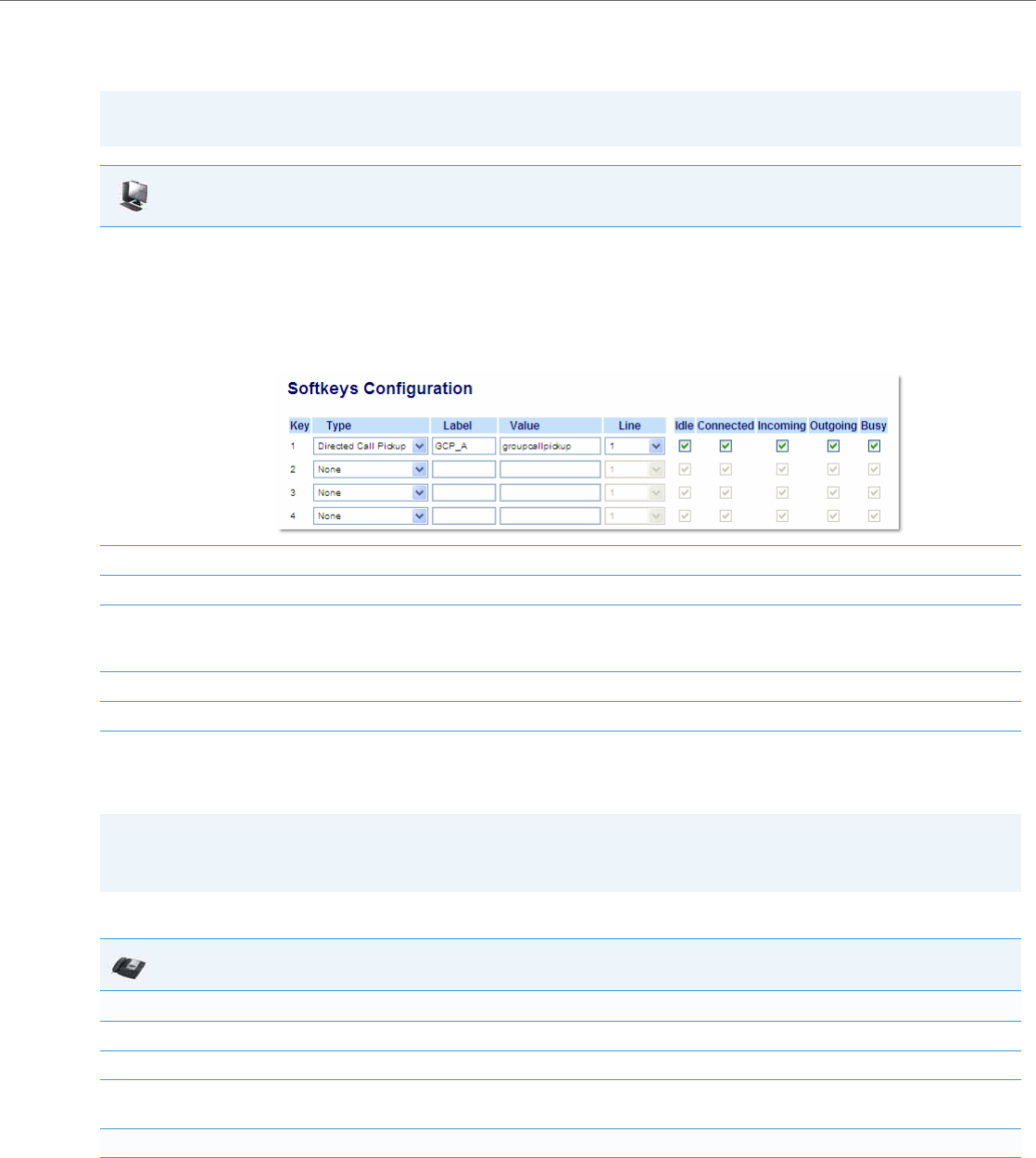
Operational Features
41-001343-02 REV04 – 05.2014 5-155
Configuring Group Call Pickup (GCP) Using the Aastra Web UI
Use the following procedure to configure Group Call Pickup using the Aastra Web UI.
Using Directed Call Pickup/Group Call Pickup
Use the following procedure for the DCP/GCP on your phone.
Note:
A ring group must be configured on the server in order for a GCP softkey to function.
Aastra Web UI
1. Click on Operation->Softkeys and XML
or
Click on Operation->Programmable Keys
or
Click on Operation->Expansion Module <N>.
Depending on your phone-model, the key configuration screen displays. The 6755i Key Screen is shown as an example.
2. Select a key for which to configure Group Call Pickup.
3. In the “Type” field, select Directed Call Pickup.
4. In the “Label” field, specify a name for this Directed Call Pickup softkey.
For example: GCP_A
5. In the “Value” field, enter groupcallpickup.
6. Click Save Settings to save your changes.
Note:
Before using the DCP/GCP feature on your phone, you must first configure the DCP or GCP key. You must identify the
extension(s) or phone number(s) you want to monitor when configuring the key.
IP Phone UI
Using Directed Call Pickup (DCP)
1. When the monitored extension receives a call, press the DCP softkey to pick up the call.
2. If the monitored extension receives multiple incoming calls simultaneously, the phone displays a list of incoming calls.
3. Select a call from this list using the UP and DOWN arrow keys.
The call is answered.
Using Group Call Pickup (GCP)
1. When any of the monitored group of extensions receives a call, press the GCP softkey to pick up the call.
The call is answered.

Operational Features
5-156 41-001343-02 REV04 – 05.2014
Do Not Disturb (DND)
The IP phones have a feature you can enable called "Do Not Disturb (DND). An Administrator or User can set “Do Not Dis-
turb” based on the accounts on the phone (all accounts or a specific account). You can set specific modes for the way you
want the phone to handle DND. The three modes you can set on the phone for DND are:
•Account
•Phone
•Custom
DND Account-Based Configuration
An Administrator or User can configure DND on the phone-side by setting a mode for the phone to use (account,
phone, or custom). Once the mode is set, you can use the IP Phone UI to use the DND feature.
The following describes the DND key behavior for each DND mode.
•Account - DND key toggles the account in focus on the IP Phone UI, to ON or OFF if DND enabled for that account.
•Phone - DND key toggles all accounts on the phone to ON or OFF.
•Custom - DND key displays custom screens on the IP Phone UI. User can select whether to enable/disable DND per
account, enable DND on all accounts, or disable DND on all accounts.
The following table describes the DND key and Message Waiting Indicator (MWI) LEDs when you enable DND on the IP
Phone.
You can configure the DND softkey and the DND mode (Account, Phone, Custom) using the configuration files or the
Aastra Web UI. Once you configure DND, you can access the DND screen on the IP Phone UI.
2. If the monitored extension receives multiple incoming calls simultaneously, the phone displays a list of incoming calls.
3. Select a call from this list using the UP and DOWN arrow keys.
Press the "Pickup" softkey to answer the call you selected.
Notes:
•If there is only one account configured on the phone, then the mode setting is ignored and the phone behaves as if
the mode was set to “Phone”.
•You must configure a DND key on the phone to be able to use this feature via the phone’s keypad.
Softkey LED Behavior
for All Modes
MWI LED Behavior
for All Modes
DND key LED RED if current account in focus has DND ON.
DND key LED OFF when current account in focus has DND disabled.
MWI LED ON if current account in focus has DND ON.
MWI LED OFF if current account in focus has DND OFF.
Notes:
•In the Aastra Web UI, the “Account Configuration” page replaces the previous “Call Forward Settings” page.
•In the IP Phone UI, the new DND key feature now has new menu screens.
•If you make changes to the configuration for DND via the IP Phone UI, you must refresh the Aastra Web UI screen to
see the changes.
•On the 6739i, you can configure a DND softkey using the IP Phone UI also. For more information, see the Aastra
Model 6739i IP Phone User Guide.
IP Phone UI

Operational Features
41-001343-02 REV04 – 05.2014 5-157
Configuring DND Using the Configuration Files
You use the following parameters to configure DND on the IP Phone:
•dnd key mode
•softkeyN type, topsoftkeyN type, prgkeyN type, or expmodX keyN type
•softkeyN states (optional)
Example
The following is an example of configuring the mode for DND in the configuration files:
dnd key mode: 2
softkey1 type: dnd
softkey1 states: idle connected incoming outgoing busy
In the above example, softkey 1 is configured for DND for line 1 only, with a “custom” configuration. Pressing softkey 1 dis-
plays DND screens for which you can customize on the phone.
Note:
If there is no DND key configured or if it is removed, DND is disabled on the IP Phone.
Configuration Files
To set DND in the configuration files, see Appendix A, the sections:
•“DND Key Mode Settings” on pageA-127.
•“Softkey/Programmable Key/Keypad Key/Feature Key/Expansion Module Key/Hard Key Parameters” on pageA-156.
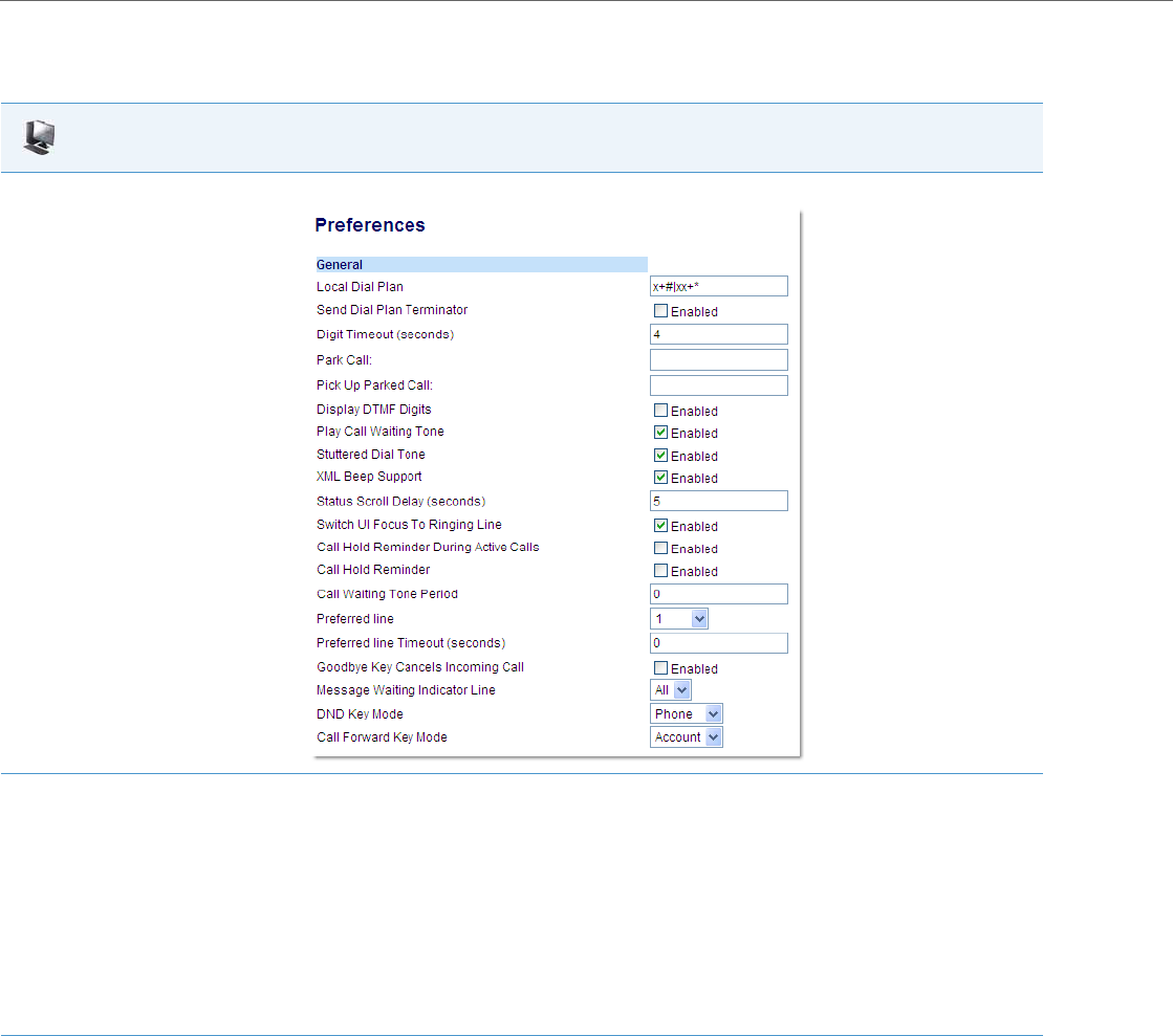
Operational Features
5-158 41-001343-02 REV04 – 05.2014
Configuring DND Using the Aastra Web UI
Use the following procedure to configure DND mode using the Aastra Web UI:
Aastra Web UI
1. Click on Basic Settings->Preferences->General.
2. In the “DND Key Mode” field, select a “do not disturb” (DND) mode to use on the phone.
Valid values are: Account, Phone, Custom. Default is Phone.
•Account Sets DND for a specific account. DND key toggles the account in focus on the
IP Phone UI, to ON or OFF.
•Phone Sets DND ON for all accounts on the phone. DND key toggles all accounts on the
phone to ON or OFF.
•Custom Sets the phone to display custom screens after pressing the DND key, that list the
account(s) on the phone. The user can select a specific account for DND, turn
DND ON for all accounts, or turn DND OFF for all accounts.
Notes:
•If there is only one account configured on the phone, then the mode setting is ignored and the phone behaves as if the mode was set to
“Phone”.
•Using the Aastra Web UI, if you change the DND Key Mode to “phone”, all accounts synchronize to the current setting of Account 1.
3. Click Save Settings to save your changes.
The change takes effect immediately without a reboot.
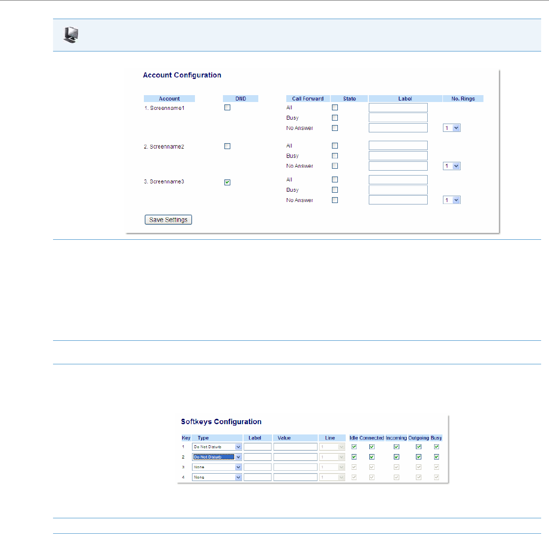
Operational Features
41-001343-02 REV04 – 05.2014 5-159
4. Click on Basic Settings->Account Configuration.
5. For each account, enable DND by placing a check mark in the box. Disable DND by unchecking the box.
Notes:
•If you selected “Account” or “Custom” mode in step 2, you can enable/disable each account or all accounts as applicable.
If you selected “Phone” mode, the first account allows you to change the DND status for all accounts.
•Number and name of accounts that display to this screen are dependant on the number and name of accounts configured on the phone.
In the screen in step 4, Screenname1 is configured on Line 1, Screenname2 is configured on Line 2, and Screenname3 is configured on Line
3. The name for the account is dependant on the name specified for the “Screen Name” parameter at the path Advanced Settings->LineN.
If you do not specify a value for the “Screen Name” parameter, the account name is based on the “Phone Number” parameter at the path
Advanced Settings->LineN. If neither the “Screen Name” nor the “Phone Number” parameters are specified, the account name shows “1”, “2”,
“3”, etc. only.
6. Click Save Settings to save your changes.
The change takes effect immediately without a reboot.
7. Click on Operation->Softkeys and XML;
or
Click on Operation->Programmable Keys;
or
Click on Operation->Expansion Module.
Note:
If there is no DND key configured or if it is removed, DND is disabled on the IP Phone.
8. Click Save Settings to save your changes.
Aastra Web UI
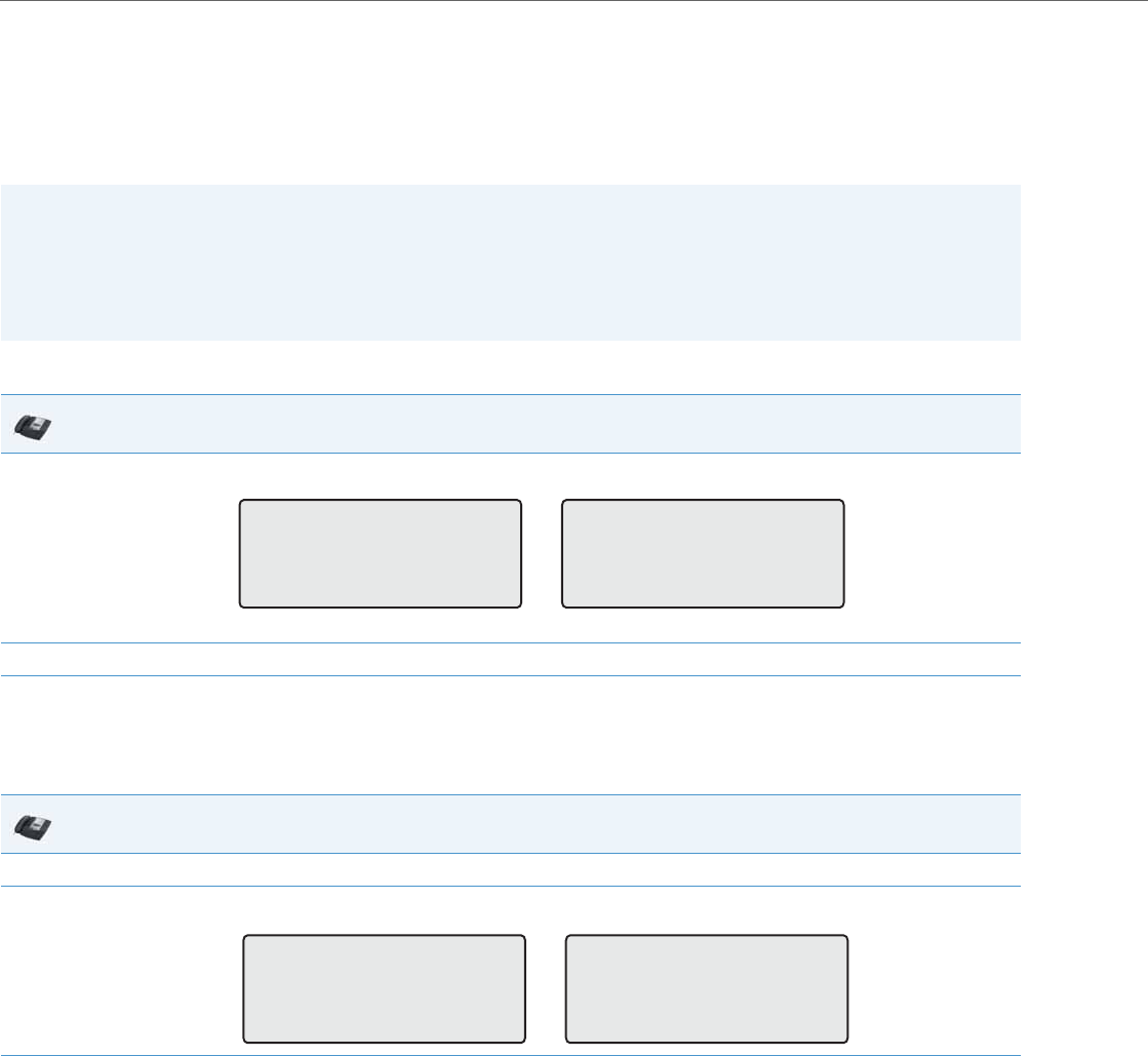
Operational Features
5-160 41-001343-02 REV04 – 05.2014
Configuring DND via the IP Phone UI (3-Line Phones)
After you add a DND key to your phone, you can toggle the DND state using this key on the phone. Use the following
procedure to enable/disable DND on the IP phone.
The following procedures assume you have already configured a DND key AND assumes there are two accounts config-
ured on the phone.
DND in Account Mode
In the above example, two accounts are configured on the phone. Only account 1 has DND enabled while account 2 has
DND disabled.
DND in Phone Mode (Default)
In the above example, enabling DND for account 1 also enables DND for account 2.
Notes:
•If there is no DND key configured or if it is removed, DND is disabled on the IP phone.
•If there is only one account configured on the phone, then the mode setting is ignored and the phone behaves as if
the mode was set to Phone.
•Using the Aastra Web UI, if you change the DND key mode to Phone, all accounts synchronize to the current setting
of Account 1.
IP Phone UI
1. Use the 3 and 4 navigation keys to scroll through each account.
2. With the account in focus on the IP phone UI, press the DND key to turn on/off DND for the account.
IP Phone UI
1. Press the DND key to turn on/off DND for all accounts on the phone.
2. Use the 3 and 4 navigation keys to scroll through each account.
John Smith
DND On
Tue Aug 20 2:55pm
L1 J. Smith
Tue Aug 20 2:55pm
L2
John Smith
DND On
Tue Aug 20 2:55pm
L1 J. Smith
DND On
Tue Aug 20 2:55pm
L2
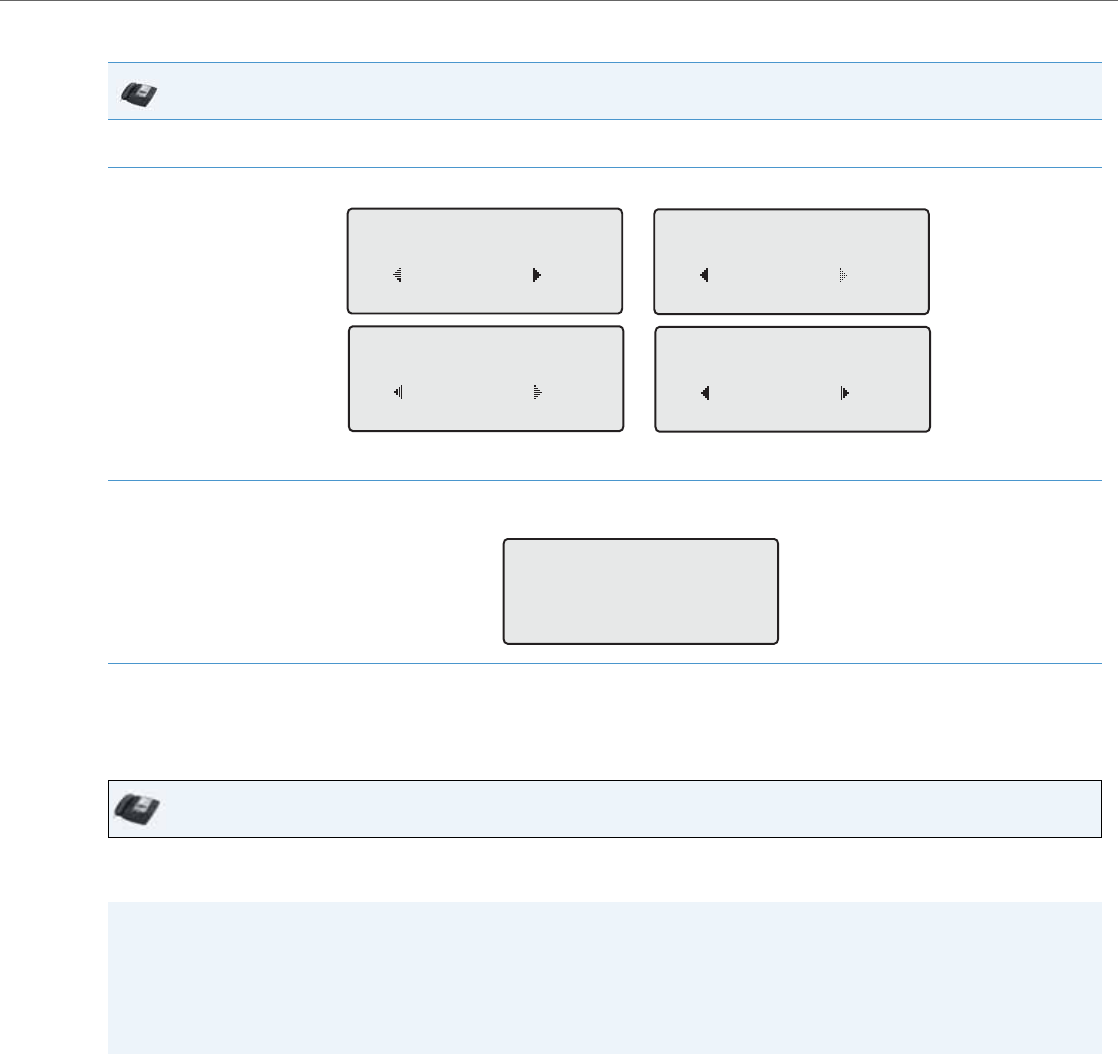
Operational Features
41-001343-02 REV04 – 05.2014 5-161
DND in Custom Mode
Configuring DND via the IP Phone UI (8-Line and 11-Line Phones)
After you add a DND key to your phone, you can toggle the DND state using this key on the phone. Use the following pro-
cedure to enable/disable DND on the IP Phone.
The following procedures assume you have already configured a DND key AND assumes there are three accounts config-
ured on the phone.
IP Phone UI
1. Press the DND key on the phone. The screen displays a list of the accounts on the phone and allows you to enable/disable a specific account
or all accounts.
2. Use the 2 and 5 navigation keys to scroll through the accounts.
In the above example, account 1 has DND enabled as indicated by a check mark (). Account 2 has DND disabled as indicated by an X. Items
3 and 4 allow you to disable or enable DND on all accounts, respectively.
3. Use the 4 Change key to enable or disable DND for a specific account or to enable/disable DND for all accounts.
After making the change, press 3 Done and then # Confirm to save the change. Pressing 0 Cancel cancels the attempted change.
IP Phone UI
Notes:
•If there is no DND key configured or if it is removed, DND is disabled on the IP Phone.
•If there is only one account configured on the phone, then the mode setting is ignored and the phone behaves as if
the mode was set to “Phone”.
•Using the Aastra Web UI, if you change the DND key mode to “phone”, all accounts synchronize to the current setting
of Account 1.
DND
John Smith
Done Change
1
DND
J. Smith X
Done Change
2
DND
All Off
Done Change
3
DND
All On
Done Change
4
Apply Changes
0Cancel
#Confirm
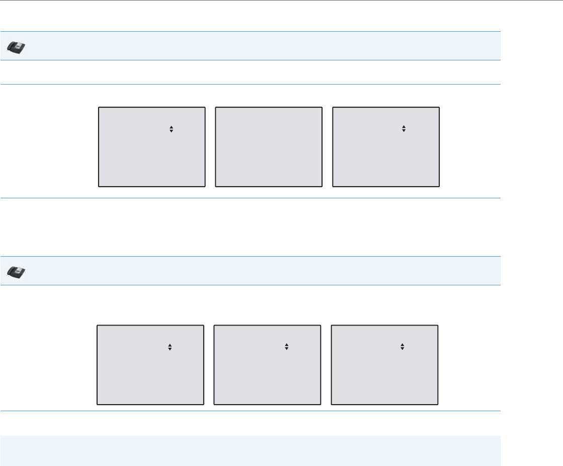
Operational Features
5-162 41-001343-02 REV04 – 05.2014
DND in Account Mode
In the above example, Screenname1, Screenname2, and Screenname3, are three accounts configured on the phone.
Only Screenname1 and 3 have DND ON. Screenname 2 has DND OFF.
DND in Phone Mode (Default)
In the above example, toggling Screenname1 to DND ON, enabled DND for Screenname2 and 3 also.
IP Phone UI
1. With the account in focus on the IP Phone UI, press the DND key to toggle DND ON or OFF for the account. Use the RIGHT and LEFT arrow
keys to scroll through each account.
2. Use the RIGHT and LEFT arrow keys to scroll through each account.
IP Phone UI
1. Press the DND key to toggle DND ON or OFF for all accounts on the phone. Toggling to ON enables DND on all accounts on the phone. Tog-
gling to OFF disables DND on all accounts on the phone. Use the RIGHT and LEFT arrow keys to scroll through each account. Use the RIGHT
and LEFT arrow keys to scroll through each account.
Note:
Enabling DND in “Phone” mode toggles all accounts on the phone to DND ON.
DND
01/01/14 11:00am
L1 Screenname1
DND On
DND
01/01/14 11:00am
L2 Screenname 2
DND
01/01/14 11:00am
L3 Screenname 3
DND On
DND
01/01/14 11:00am
L1 Screenname1
DND On
DND
01/01/14 11:00am
L2 Screenname 2
DND
01/01/14 11:00am
L3 Screenname 3
DND On
DND On
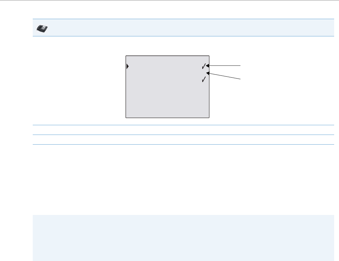
Operational Features
41-001343-02 REV04 – 05.2014 5-163
DND in Custom Mode
In the above example, Screenname1 and 3 have DND ON as indicated by a check mark (). Screenname2 has DND off as
indicated by an X. The ALL ON and ALL OFF softkeys allow you to enable or disable DND on all accounts, respectively.
Configuring DND Modes via the IP Phone UI (6739i)
If you add a DND key using the configuration files or the Aastra Web UI, you can toggle the DND state using the. Use the
following procedure to enable/disable DND on the IP Phone.
The following procedure assumes you have already configured a DND key AND assumes there are three accounts config-
ured on the phone.
IP Phone UI
1. Press the DND key on the phone. The screen displays a list of the accounts on the phone and allows you to enable/disable a specific account
or all accounts. Use the UP and DOWN arrow keys to scroll through the accounts.
2. You use the CHANGE key to enable or disable DND for a specific account selected.
3. Press DONE to save the change.
Notes:
•If there is no DND key configured or if it is removed, DND is disabled on the IP Phone.
•If there is only one account configured on the phone, then the mode setting is ignored and the phone behaves as if
the mode was set to “Phone”.
•Using the Aastra Web UI, if you change the DND key mode to “phone”, all accounts synchronize to the current setting
of Account 1.
Indicates
Indicates
DND On
DND Off
2.Screenname2 X
3.Screenname3
Change Cancel
All Off
All On Done
DND
1.Screenname1
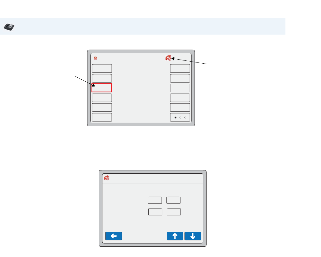
Operational Features
5-164 41-001343-02 REV04 – 05.2014
DND in Account Mode
IP Phone UI
1. On the 6739i:
With the account in focus on the , press the DND key to toggle DND ON or OFF for the account.
In the above example, pressing the DND key on the line in focus highlights the softkey in red to show that DND is enabled. The MWI LED illu-
minates ON. A DND icon appears in the status bar on the upper right of the screen. Pressing the DND key again disables DND on the line in
focus, turns off the MWI LED, and the DND status icon disappears.
To enable/disable DND for another account:
•Press the <Services> button.
•Press the <DND> button.
•Press <On> or <Off> to enable/disable DND for a specific account. Use the scroll keys if applicable to scroll through accounts.
L1 John Smith 401 12 : 45pm
Mon Jan 1
John Smith
401
Home
DND
404
Call Forward
406
Flash
Intercom
Paging
Park
Pickup
402
DND Status Icon
DND Softkey
DND>Account 12 : 45pm
Mon Jan 1
On
John
Sue
Off
On Off
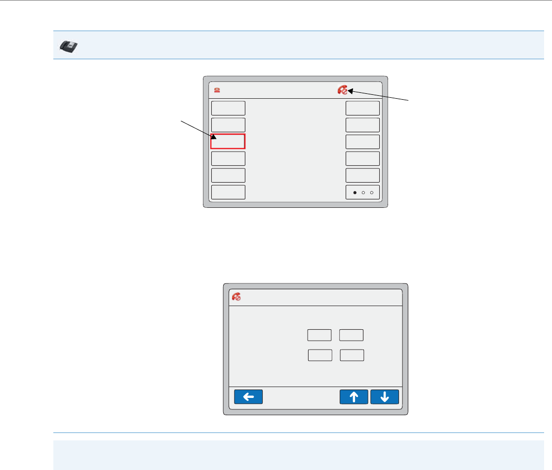
Operational Features
41-001343-02 REV04 – 05.2014 5-165
DND in Phone Mode (Default)
IP Phone UI
1. With the account in focus on the , press the DND key to toggle DND ON or OFF for the account.
In the above example, pressing the DND key on the line in focus highlights the softkey in red to show that DND is enabled. The MWI LED illu-
minates ON. A DND icon appears in the status bar on the upper right of the screen. Pressing the DND key again disables DND on the line in
focus, turns off the MWI LED, and the DND status icon disappears.
To enable/disable DND for another account:
•Press the <Services> button.
•Press the <DND> button.
•Press <On> or <Off> to enable/disable DND for a specific account. Use the scroll keys if applicable to scroll through accounts.
Note:
Enabling DND in Phone mode toggles all accounts on the phone to DND on.
L1 John Smith 401 12 : 45pm
Mon Jan 1
John Smith
401
Home
DND
404
Call Forward
406
Flash
Intercom
Paging
Park
Pickup
402
DND Status Icon
DND Softkey
DND>Account 12 : 45pm
Mon Jan 1
On
John
Sue
Off
On Off
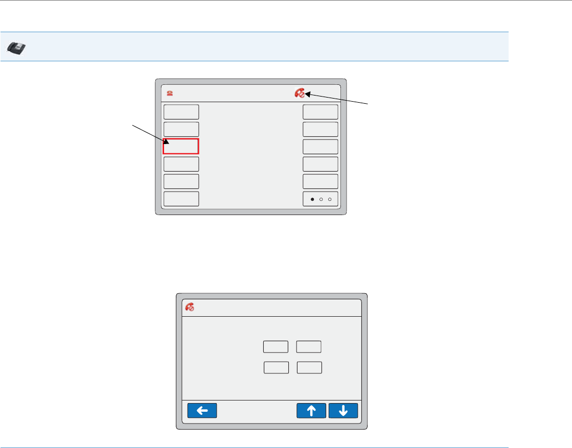
Operational Features
5-166 41-001343-02 REV04 – 05.2014
DND in Custom Mode
IP Phone UI
1. With the account in focus on the , press the DND key to toggle DND ON or OFF for the account.
In the above example, pressing the DND key on the line in focus highlights the softkey in red to show that DND is enabled. The MWI LED illu-
minates ON. A DND icon appears in the status bar on the upper right of the screen. Pressing the DND key again disables DND on the line in
focus, turns off the MWI LED, and the DND status icon disappears.
To enable/disable DND for another account:
•Press the <Services> button.
•Press the <DND> button.
•Press <On> or <Off> to enable/disable DND for a specific account. Use the scroll keys if applicable to scroll through accounts.
L1 John Smith 401 12 : 45pm
Mon Jan 1
John Smith
401
Home
DND
404
Call Forward
406
Flash
Intercom
Paging
Park
Pickup
402
DND Status Icon
DND Softkey
DND>Account 12 : 45pm
Mon Jan 1
On
John
Sue
Off
On Off
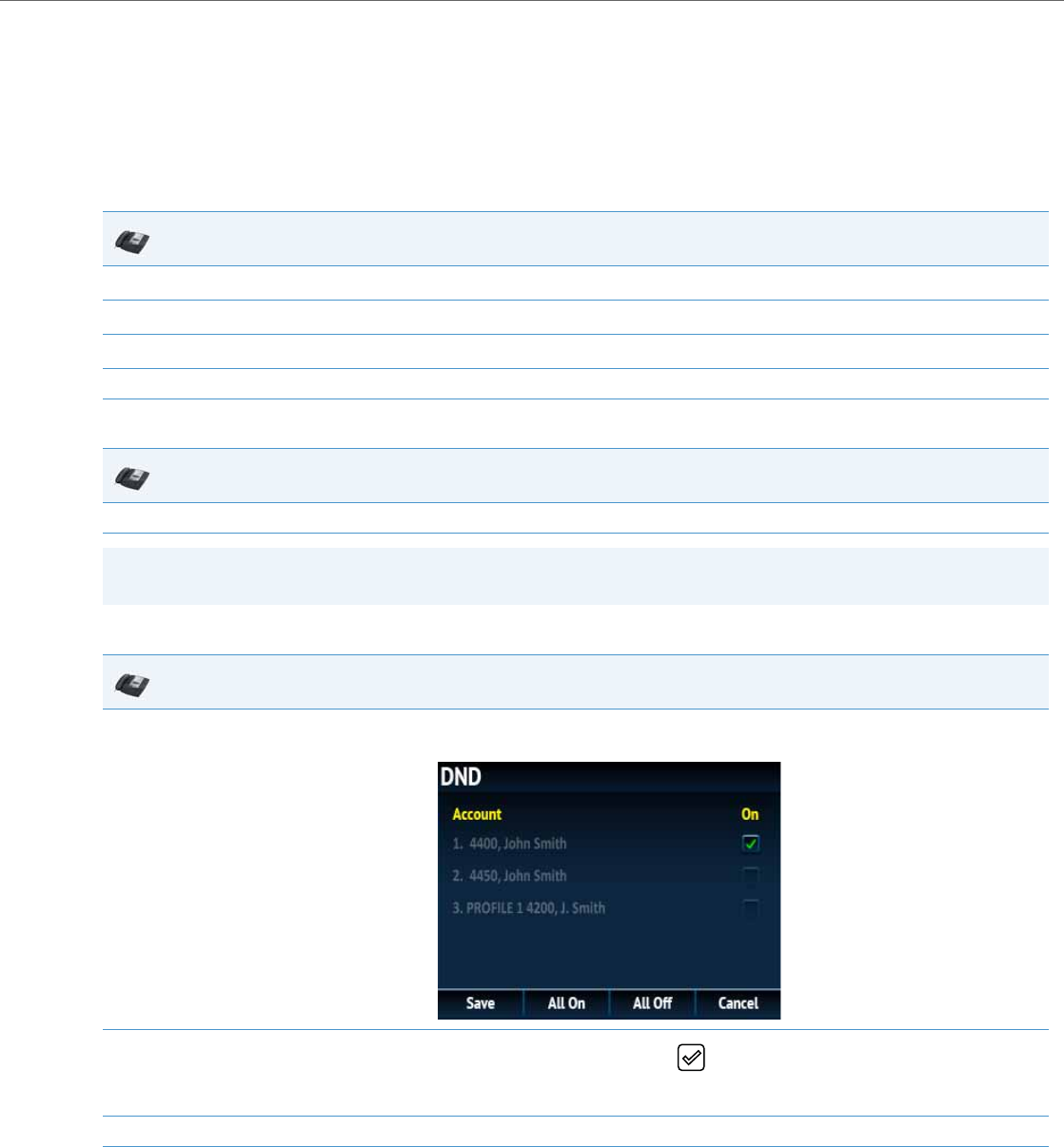
Operational Features
41-001343-02 REV04 – 05.2014 5-167
Configuring DND Using the IP Phone UI (6867i)
After you add a DND key to your phone, you can toggle the DND state using this key on the phone. Use the following pro-
cedure to enable/disable DND on the IP phone.
The following procedures assume you have already configured a DND key AND assumes there are multiple accounts con-
figured on the phone.
DND in Account Mode
DND in Phone Mode (Default)
DND in Custom Mode
IP Phone UI
1. From the Home screen press the 4 navigation key to move to the Line Selection screen.
2. Highlight the desired account using the 2 and 5 navigation keys.
3. Press the 3 navigation key to go back to the Home screen
4. With the account in focus on Home screen, press the DND softkey to toggle DND on or off for the account.
IP Phone UI
1. From the Home screen, press the DND softkey to toggle DND on or off for all accounts on the phone.
Note:
Enabling DND in Phone mode toggles all accounts on the phone to DND on.
IP Phone UI
1. From the Home screen, press the DND softkey.
The screen displays a list of the accounts on the phone and allows you to enable/disable a specific account or all accounts.
2. Use the 2 and 5 navigation keys to scroll through the accounts and press the button to enable DND for the selected account.
Note:
Press the All On or All Off softkeys to quickly enable or disable DND for all accounts.
3. Press the Save softkey to save your changes.

Operational Features
5-168 41-001343-02 REV04 – 05.2014
Bridged Line Appearance (BLA)
A SIP bridge line appearance (BLA) on the IP phones allows multiple devices to share a single directory address (DA).
For example, people working at a technical support department could be located in different places. If their desktop
phones are configured for BLA DA, when customer calls come in, all the phones with the BLA DA would ring but the call
can only be answered by one of them.
Once the call is answered, the rest of the phones reflect the status of the call. If the call was put on "hold" by the original
recipient, any one from the group can pick up the call.
You can apply BLA on the IP phones as follows:
•As a single BLA group - One BLA DA is shared among multiple phones. Only one phone at a time can pick up an
incoming call or initiate an outgoing call on the BLA DA. All phones reflect the usage of the BLA DA. If the call is put on
"hold", any one from the group can pick up the "held" call.
•As a multiple BLA group - On one single phone, multiple BLA DA can be associated with different line appearances.
Every BLA DA is independent from each other and follows the same rules as "a single BLA group".
•As multiple instances of a BLA DA - A "x-line-id" parameter was defined in draft-anil-sipping-bla-02.txt to present
the incoming call to or place an outgoing call on the specified line appearance instance. The parameter is carried in
"Alert-Info" header field over the request-URI (INVITE e.g.) or in the NOTIFY messages to report the status of a dialog.
BLA DA can be configured on a global basis or on a per-line basis on the IP phones using the Aastra Web UI or the config-
uration files.
The following table shows the number of lines that can be set to BLA for each model phone.
Configuring BLA
You can configure BLA on a global or per-line basis using the configuration files or the Aastra Web UI.
Note:
This feature is dependent on the IP telephony system to which the IP phone is registered and according to draft-anil-
sipping-bla-02.txt.
IP Phone Model Possible # of BLA Lines
9143i 9
9480i 9
9480i CT 9
6730i 6
6731i 6
6735i 9
6737i 9
6739i 9
6753i 9
6755i 9
6757i 9
6757i CT 9
6863i 2
6865i 9
6867i 9

Operational Features
41-001343-02 REV04 – 05.2014 5-169
Global BLA
You configure BLA on a global basis in the configuration files using the following parameters:
•sip mode
•sip user name
•sip bla number
You configure BLA on a global basis in the Aastra Web UI using the following fields at Advanced Settings->Global SIP-
>Basic SIP Authentication Settings:
•Line Mode
•Phone Number
•BLA Number
Per-Line BLA
You configure BLA on a per-line basis in the configuration files using the following parameters:
•sip lineN mode
•sip lineN username
•sip lineN bla number
You configure BLA on a per-line basis in the Aastra Web UI using the following fields at Advanced Settings->Line 1 thru
Line 9:
•Line Mode
•Phone Number
•BLA Number
Sylantro servers and ININ servers require specific configuration methods for per-line configurations.
For Sylantro Server
When configuring the BLA feature on a per-line basis for a Sylantro server, the value set for the "sip lineN bla number"
parameter shall be the same value set for the "sip lineN user name" parameter for all the phones in the group. For exam-
ple, if sip lineN user name is 1010, you would configure BLA on a per-line basis for the Sylantro server as follows:
sip line 1 mode: 3
sip line1 user name: 1010 (# for all the phones)
sip line1 bla number: 1010
For ININ Server
When configuring the BLA feature on an ININ server, the value set for the sip lineN bla number parameter shall be the
same value set for the sip lineN user name parameter without the incremented digit added to the phone #. For example, if
the sip lineN user name for the first phone is 10101, and the sip lineN user name for the second phone is 10102, etc., you
would configure BLA on a per-line basis for the ININ server as follows:
(# for phone 1 with appearance of phone 3)
sip line1 mode: 3
sip line1 user name: 10101 sip line1 bla number: 1010
(# for phone 2 with appearance of phone 3)
sip line1 mode: 3
sip line1 user name: 10102
sip line1 bla number: 1010
(# for phone 3)
sip line1 mode: 3
sip line1 user name: 1010

Operational Features
5-170 41-001343-02 REV04 – 05.2014
sip line1 bla number: 1010
Configuring Global BLA Using the Configuration Files
Use the following procedures to configure global BLA on the IP phone.
Configuring Per-Line BLA Using the Configuration Files
Use the following procedures to configure per-line BLA on the IP phone.
Note:
The original phone number which has the bridged line appearance on other phones, will have the "sip lineN user
name" parameter the same as the "sip lineN bla number" (1010 in the above example on Phone 3).
Configuration Files
For specific global parameters you can set in the configuration files, see Appendix A, the section,
“SIP Basic, Global Settings” on pageA-61.
Configuration Files
For specific per-line parameters you can set in the configuration files, see Appendix A, the section, “SIP Basic, Per-Line Settings” on pageA-69.
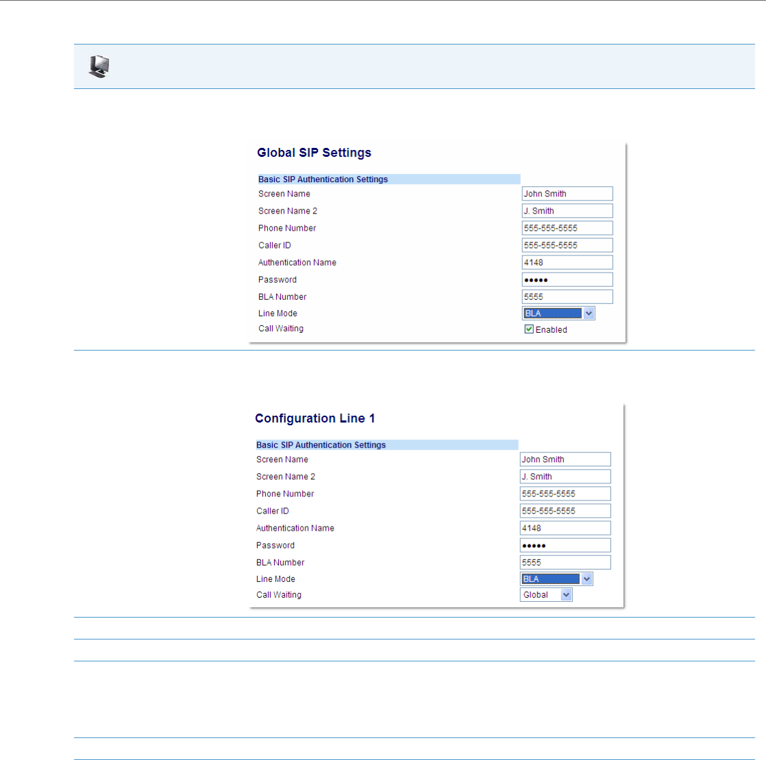
Operational Features
41-001343-02 REV04 – 05.2014 5-171
Configuring BLA Using the Aastra Web UI
Aastra Web UI
1. For global configuration of BLA:
Click on Advanced Settings->Global SIP->Basic SIP Authentication Settings.
For per-line configuration of BLA:
Click on Advanced Settings->Line N (1-9).
In the "Line Mode" field, select the BLA option.
2. In the "Phone Number" field, enter the phone number of the IP phone.
3. For global configuration of BLA:
In the "BLA Number" field, enter the Bridge Line Appearance (BLA) number to be shared across all IP phones.
For per-line configuration of BLA:
In the "BLA Number" field, enter the Bridge Line Appearance (BLA) number to be shared on a specific line.
4. Click Save Settings to save your changes.
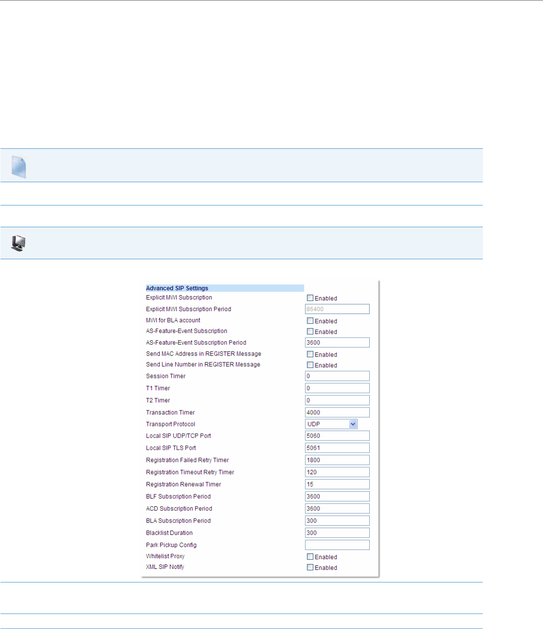
Operational Features
5-172 41-001343-02 REV04 – 05.2014
BLA Subscription Period
The IP Phones include a SIP BLA subscription period parameter that allows an Administrator to set the amount of time,
in seconds, of the BLA subscription period.
If this parameter is set to zero (0), the phone uses the value specified for the BLA expiration in the subscribe message
received from the server. If no value is specified in the Subscribe message received from the server, the phone uses the
default value of 300 seconds.
You can configure this parameter using the configuration files or the Aastra Web UI.
Configuring the BLA Subscription Period
Use the following procedures to configure the BLA Subscription Period.
Configuration Files
To configure the BLA subscription period on the IP phones using the configuration files, see Appendix A, the section, “Advanced SIP Settings” on
pageA-82.
Aastra Web UI
1. Click on Advanced Settings->Global SIP->Advanced SIP Settings.
2. In the “BLA Subscription Period” field, enter a value, in seconds, that the phone waits to receive a BLA subscribe message from the server.
If you specify zero (0), the phone uses the value specified for the BLA expiration in the subscribe message received from the server. If no
value is specified, the phone uses the default value of 300 seconds. Valid values are 0 to 3700. Default is 300 seconds.
3. Click Save Settings to save your changes.

Operational Features
41-001343-02 REV04 – 05.2014 5-173
Using a BLA Line on the IP Phone
If you have either a global or per-line BLA configuration, and you want to share a call on the line with a BLA group, you
need to press the Hold button before sharing the call with the group.
For example, if line 1 is configured for BLA, and you pick up a call on line 1, you must press the Hold button to share the call
with the BLA group.
If you pick up a call on line 1 configured for BLA, and another call comes in on line 2, you can pick up line 2 without putting
line 1 on hold. The line 1 call will be on hold automatically; however it is on hold locally only. The line 1 call cannot be
shared with the BLA group.
BLA Support for Third-Party Registration
BLA allows an Address Of Record (AOR) to be assigned onto different line appearances for a group of SIP user agents (IP
phones). When a call is made to this BLA number, the call is offered to all user agents that have mapping to this BLA. To
support this, the IP phones need to support third party registration for the BLA along with the registration for its own pri-
mary appearance number. If the IP phone has the primary appearance as a BLA, then there is no need for third party regis-
tration.
When configuring the BLA feature on a per-line basis for third party registration and subscription, the third party name
must be configured using the “sip lineN bla number” parameter. For third party registration to work effectively, one of
the lines should register as generic with its own username.
For example, Bob has Alice’s appearance on his phone. Bob’s configuration is as follows:
#line 1 Bob
sip line1 auth name:4082272203
sip line1 password:
sip line1 mode: 0
sip line1 user name:4082272203
sip line1 display name:Bob
sip line1 screen name:Bob
#line 2 Alice
sip line2 auth name:4082272203
sip line2 password:
#BLA mode 3
sip line2 mode: 3
sip line2 user name:4082272203
#Alice phone number
sip line2 bla number:4085582868
sip line2 display name:Alice
sip line2 screen name:Alice
Alice’s configuration is as follows:
#line 1
sip line1 auth name:4085582868
sip line1 password:
sip line1 mode: 3
sip line1 user name:4085582868
sip line1 display name: Alice
sip line1 screen name: Alice
Note:
The Hold button must be pressed for a call on a BLA line to be shared with the BLA group.

Operational Features
5-174 41-001343-02 REV04 – 05.2014
P-Preferred Identity Header for BLA Accounts
The IP Phones support the BLA specification, draft-anil-sipping-bla-02, which states that the P-Preferrred-Identity header
(RFC3325) gets added to the INVITE message to indicate the Caller-ID that is used for the call.
BLA Support for Message Waiting Indicator (MWI)
The IP Phones have an option for a Busy Line Appearance (BLA) configured line to send a SUBSCRIBE SIP message for a
Message Waiting Indicator (MWI).
You can configure this feature using the configuration files or the Aastra Web UI.
Limitations
The following are limitations of the BLA Support for MWI feature:
•The phone shows MWI for the first matching identity if more than one line with different user names has the same BLA
account.
•If a normal line has the same user name as the BLA user of another line, the phone shows MWI only for the normal line.
Configuring BLA Support for MWI Using the Configuration Files
Use the following procedure to configure BLA support for MWI.
Note:
The P-Preferred-Identity for BLA accounts is also sent for hold/unhold messages.
Notes:
•If you change the setting on this parameter, you must reboot the phone for it to take affect.
•Both the “sip explicit mwi subscription” and “sip mwi for bla account” parameters must be enabled in order for the
MWI subscription for BLA to occur.
•The MWI re-subscription for the BLA account uses the value set for the "sip explicit mwi subscription period"
parameter to re-subscribe.
4.Whether or not the "sip mwi for bla account" parameter is enabled, the priority for displaying MWI does not
change.
Configuration Files
For specific parameters you can set in the configuration files, see Appendix A, the section,“BLA Support for MWI” on pageA-77.
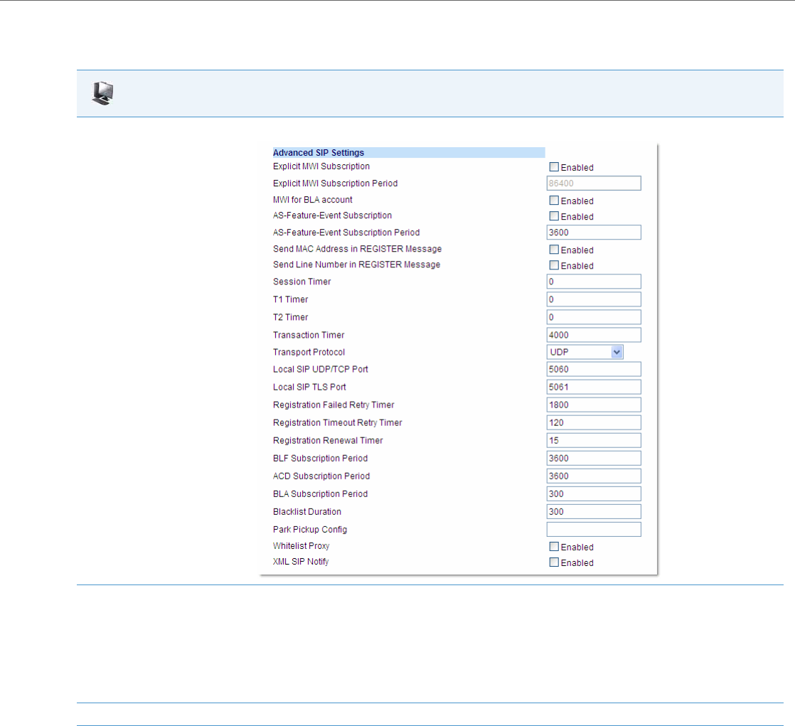
Operational Features
41-001343-02 REV04 – 05.2014 5-175
Configuring BLA Support for MWI Using the Aastra Web UI
Use the following procedure to configure BLA support for MWI.
Aastra Web UI
1. Click on Advanced Settings->Global SIP->Advanced SIP Settings.
2. The “MWI for BLA Account” field is disabled by default. To enable this feature, place a checkmark in the “Enabled” box.
Notes:
•If you change the setting on this parameter, you must reboot the phone for it to take affect.
•Both the “sip explicit mwi subscription” and “sip mwi for bla account” parameters must be enabled in order for the MWI subscription
for BLA to occur.
•The MWI re-subscription for the BLA account uses the value set for the "sip explicit mwi subscription period" parameter to re-subscribe.
•Whether or not the "sip mwi for bla account" parameter is enabled, the priority for displaying MWI does not change.
3. Click Save Settings to save your changes and reboot the phone for the change to take affect.
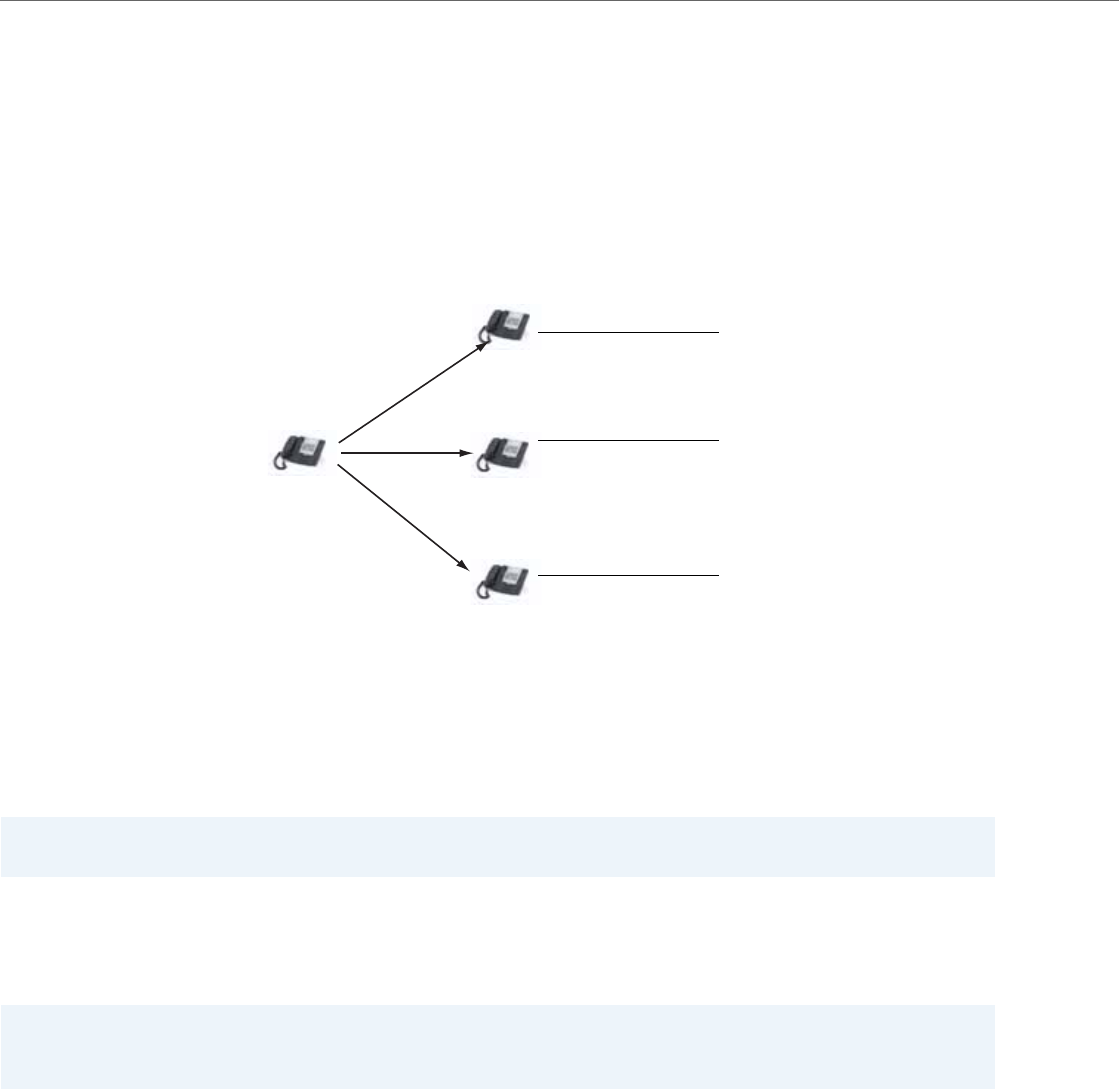
Operational Features
5-176 41-001343-02 REV04 – 05.2014
Shared Call Appearance (SCA) Call Bridging
Shared Call Appearance (SCA) is when incoming calls are presented to multiple phones simultaneously. For example, it is
the ability to assign the boss' extension to a button on the secretary's phone. Calls can be transferred between two
phones with the same extension button by simply putting the call on hold at one phone and picking it up on the other.
Status LEDs light and flash in unison, allowing all people sharing the extension to see the status at a glance.
The IP Phones include an enhanced SCA for the servers that support call bridging and allows two or more SCA users to
be connected in a call with a third party.
Refer to the following example.
Using the example above, when a call comes into Phone 1, Phone 2 and Phone 3 can pickup the same call by pressing
the SCA line key. Phone 2 and 3 display the call they are bridging into on the LCD of the phones. Existing SCA parties in a
bridge or one-to-one call hear an audible beep when another party has joined the call.
If a phone is configured for SCA bridging and it attempts to join a call, but the account on the server does not have this
functionality enabled, an error message displays to the LCD on the phone.
The SCA call bridging feature is disabled by default on all phones. You can enable this feature on a global or per-line basis
using the configuration files only.
Keys States and LED Behavior
There are two new call states on the phones that support SCA bridging:
•Bridge-active - A bridged call is in progress
•Bridge-held - The 3rd-party (i.e., non-SCA party) in the bridge is on hold.
The following tables provide the key states and LED behavior in an SCA bridge call for users involved in an SCA call and
users not involved in the SCA call.
Note:
Enabling/disabling the beep is configurable on the server-side.
Note:
A “Call-Info” header is included in the requests as well as the 200ok response to an INVITE, RE-INVITE, and UPDATE mes-
sages for SCA lines.
Phone A
Phone 1
SCA Environment
Phone 2
Phone 3
Phone A calls the SCA number and
all the phones in the SCA environment
ring.
SCA phone 1 answers.
SCA phone 2 joins by
pressing SCA line. When
When 2 and 3 pickup,
1 can hangup.
phone 1 hangs up, 2 is still
connected. Phone 2 can
press the line key to
Note: A user can place a call on hold while in an
put SCA call on hold
leaving 3 still connected
to 1.
SCA phone 3 joins by
pressing SCA line. When
phone 1 hangs up, 3 is still
connected. Phone 3 can
press the line key to
put SCA call on hold
leaving 2 still connected
to 1.
SCA bridged call, by pressing the SCA line key.

Operational Features
41-001343-02 REV04 – 05.2014 5-177
Line Keys and Idle Screens
Softkey Line Keys
9143i Phone LED States
State LED for Local Caller ID for Local LED for Remote Caller ID for Remote
Idle Off N/A Off N/A
Seized Solid Green None Solid Red None
Progressing (outgoing call) Green Called Party Solid Red None
Alerting (incoming call) Flashing Red N/A Off N/A
Active Solid Green Far-end Solid Red Far-end
Held Slow Flashing Green Far-end Slow Flashing Red Far-end
Hold private Slow Flashing Green Far-end Solid Red Far-end
Bridge-active Solid Green Far-end Solid Red Far-end
Bridge-held Slow Flashing Green Far-end Solid Red Far-end
State Icon for Local LED for Local Icon for Remote LED for Remote
Idle Small circle None Small circle None
Seized N/A N/A Solid Circle Solid Red
Progressing (outgoing call) Empty circle Solid Red Solid Circle Solid Red
Alerting (incoming call) Empty blinking circle Flashing Red N/A N/A
Active Empty circle Solid Red Solid Circle Solid Red
Held Reverse empty blinking circle Slow Flashing Red Solid Reverse Circle Slow Flashing Red
Hold private Reverse empty blinking circle Slow Flashing Red Solid Circle Solid Red
Bridge-active Empty circle Solid Red Solid Circle Solid Red
Bridge-held Reverse empty blinking circle Slow Flashing Red Solid Circle Solid Red
State LED for Local LED for Remote
Idle N/A N/A
Seized Solid Red Solid Red
Progressing (outgoing call) Solid Red Solid Red
Alerting (incoming call) Flashing Red Flashing Red
Active Solid Red Solid Red
Held Slow Flashing Red Slow Flashing Red
Hold private Slow Flashing Red Solid Red
Bridge-active Solid Red Solid Red
Bridge-held Slow Flashing Red Solid Red
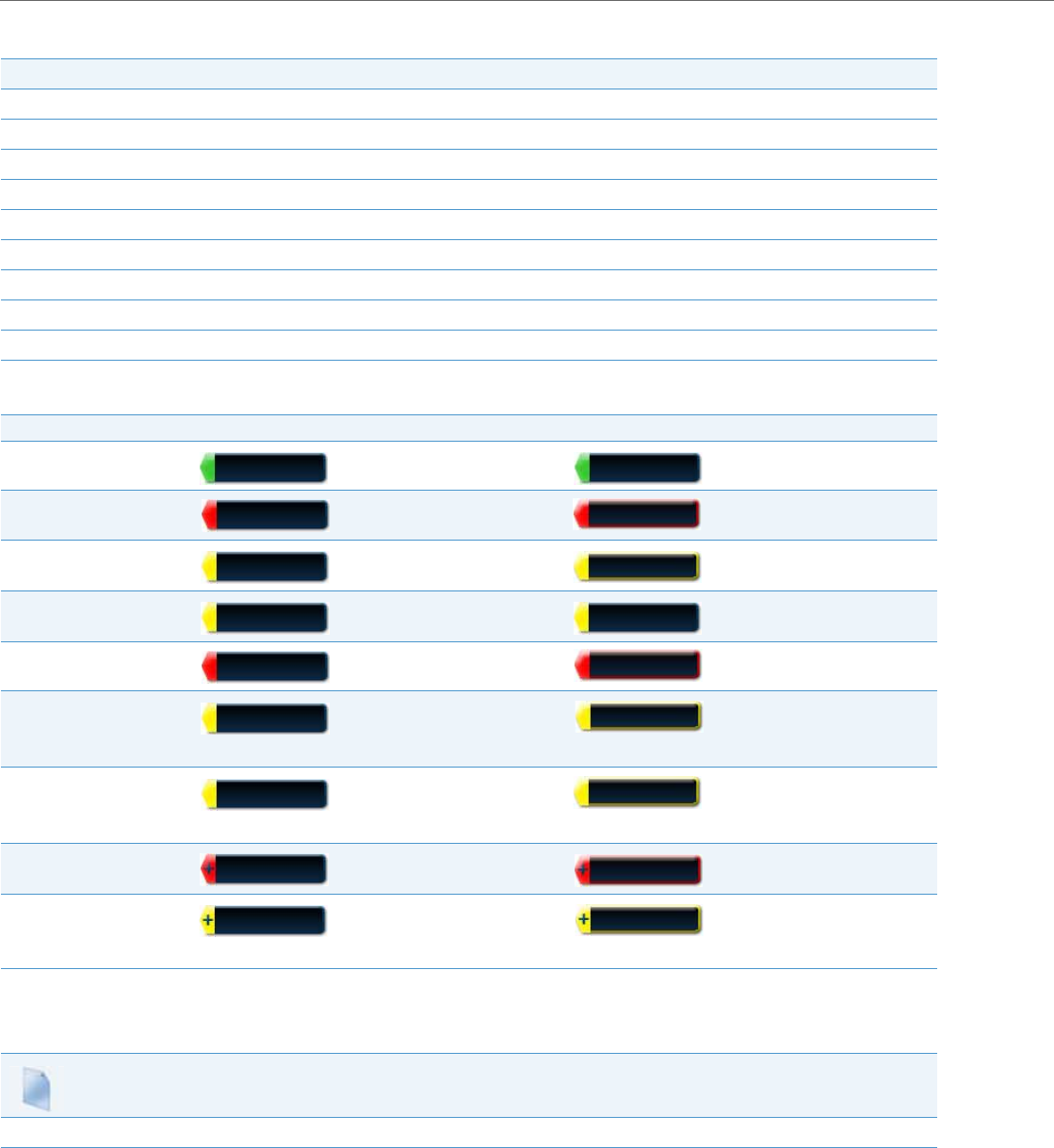
Operational Features
5-178 41-001343-02 REV04 – 05.2014
Line Key Phone Behavior
6867i Softkeys
Enabling/Disabling SCA Call Bridging Feature
Use the following procedure to enable/disable SCA call bridging on the IP Phones.
State Line Key Pressed for Local Line Key Pressed for Remote
Idle N/A Attempt to seize the line
Seized Hang up Ignore
Progressing Hang up Ignore
Alerting answer N/A
Active Hold Bridge
Held Retrieve Bridge
Hold private Retrieve Ignore
Bridge-active Hold Bridge
Bridge-held Retrieve Bridge
State Softkey Image for Local Softkey LED for Local Softkey Image for Remote Softkey LED for Remote
Idle Off Off
Seized Solid Red Solid Red
Progressing (outgoing call) Solid Red Solid Red
Alerting (incoming call) Flashing Red N/A
Active Solid Red Solid Red
Held
(Blinking)
Slow Flashing Red
(Blinking)
Slow Flashing Red
Hold Private
(Blinking)
Slow Flashing Red
(Blinking)
Solid Red
Bridge-Active Solid Red Solid Red
Bridge-Held
(Blinking)
Slow Flashing Red
(Blinking)
Solid Red
Configuration Files
For specific parameters you can set in the configuration files, see Appendix A, the section,“Shared Call Appearance (SCA) Call Bridging” on pageA-78.

Operational Features
41-001343-02 REV04 – 05.2014 5-179
Park/Pick Up Static and Programmable Configuration
The IP phones (including the CT handsets) have a park and pickup call feature that allows you to park a call and pickup a
call when required. Administrators can configure call park and pickup using a static configuration (for 8 and 11-Line LCD
phones) or by using a programmable configuration (3-Line, and 8 and 11-Line LCD phones).
Administrators can use configuration files or the Aastra Web UI to configure a park/pickup static or programmable config-
uration. Users can make changes to customize the label and the state of the park/pick up keys using the Web UI.
The IP phones support the Park/Pickup feature on the Asterisk, BroadWorks, Sylantro, and ININ PBX servers.
The following paragraphs describe the static and programmable configuration of the call park and pickup feature.
Park/Pickup Static Configuration
The static method configures park and pickup on a global basis for all supported IP phones. You can use the configuration
files or the Aastra Web UI to configure a park/pickup static configuration. In the configuration files, you use the following
parameters to statically configure park/pickup: “sprecode” and “pickupsprecode”.
In the Aastra Web UI, you use the following fields at Basic Settings -> Preferences to configure park/pickup statically:
•Park Call
•Pick Up Parked Call
How it Displays on the Phone
On the phone UI, the static configuration method displays the following:
•When a call comes in and you pickup the handset, the default label of “Park” displays on the first screen of the phone UI.
•After pressing the “Park” softkey to park the call, the default label of “Pickup” displays on the first screen of the phone
UI.
The values you enter for the Park/Pickup feature are dependant on your type of server. The following table provides the
values you enter for the “sprecode” and “pickupsprecode” parameters (configuration files), or "Park Call" and "Pickup
Parked Call" fields (Aastra Web UI).
Notes:
•The 8 and 11-LCD phones accept both methods of configuration, however to avoid redundancy, Aastra recommends
you configure either a static configuration or a programmable configuration.
•When using the IP phones with the BroadSoft BroadWorks call manager, an enhanced park/pickup configuration
method is also available to be used. For more details see “Enhanced Park/Pickup Configuration Method (BroadSoft
BroadWorks)” on page 5-185
Note:
On the 6739i, you can configure Park/Pickup softkeys using the IP Phone UI also. For more information, see the Aastra
Model 6739i IP Phone User Guide.
Note:
This feature does not work when the “collapsed context user softkey screen” parameter is enabled (see “Shifting of
Softkey Positions for Busy States” on page 5-113).
Notes:
On the 6757i CT handset, pressing Ïdisplays the “Park” and “Pickup” labels.

Operational Features
5-180 41-001343-02 REV04 – 05.2014
Park/Pickup Call Server Configuration Values
**Leave "value" fields blank to disable the park and pickup feature.
Configuring Park/Pickup Static Configuration Using the Configuration Files
Use the following parameters to configure park/pickup static configuration:
•sprecode
•pickupsprecode
Server Park Values** Pickup Values**
Asterisk 70 70
Sylantro *98 *99
BroadWorks *68 *88
ININ PBX callpark pickup
Configuration Files
For specific parameters you can set in the configuration files, see Appendix A, the section,“” on pageA-184.
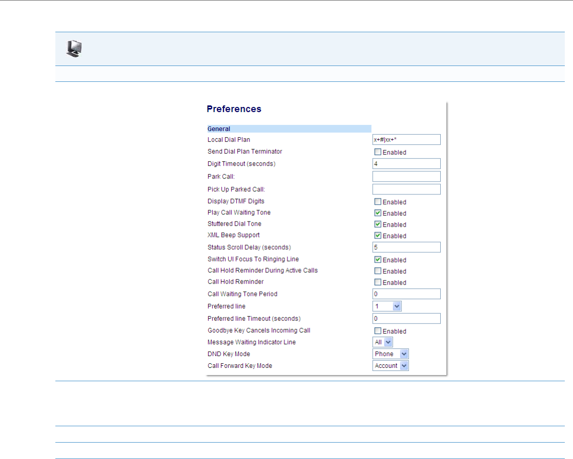
Operational Features
41-001343-02 REV04 – 05.2014 5-181
Configuring Park/Pickup Static Configuration Using the Aastra Web UI
Park/Pickup Programmable Configuration (Using a Softkey)
The programmable method of configuration creates park and pickup keys (softkeys, programmable keys, expansion mod-
ule keys) that you can configure on the IP phones.
For all 8/11-Line LCD phones and the 6739i and 6867i phones you can set a key as "Park" or "Pickup" and then:
•specify a customized label to display on the Phone UI
•specify the state of the park and/or pickup keys
For 3-Line LCD display phones, you can set a programmable key as "Park" or "Pickup".
Aastra Web UI
For 8 and 11-Line LCD Phones
1. Click on Basic Settings ->Preferences ->General
2. Enter a server value in the Park Call field to which incoming live calls will be parked.
Note:
For values to enter in this field, see the table “Park/Pickup Call Server Configuration Values” on page5-178.
3. Enter a server value in the Pick Up Parked Call field.
4. Click Save Settings to save your changes.

Operational Features
5-182 41-001343-02 REV04 – 05.2014
On 8/11-Line LCD Phone and 6739i and 6867i Phone UIs
•When a call comes in, and you pickup the handset, the custom label that you configured for the Park softkey displays
on the Phone UI.
•After the call is parked, the label that you configured for the Pickup softkey displays on other phones in the network.
You can then press the "Pickup" softkey, followed by the applicable value to pickup the call on another phone in your
network.
•On the Model CTs, the customized labels apply to the base unit only. On the Model CT handsets, pressing the Fea-
tures key displays the default labels of "Park" and "Pickup".
On 3-Line LCD Phone UIs
When a call comes in, and you pickup the handset, you can press the applicable "Park" programmable key to park the
call.
After the call is parked, you can press the "Pickup" programmable key, followed by the applicable value to pickup the call.
Configuring Park/Pickup Key Using Configuration Files
In the configuration files, you configure the park/pickup keys using the key parameters. You also must specify the "sip
lineN park and pickup config” parameter. The following examples show park/pickup configurations using specific serv-
ers.
Examples for Models with 8 /11-Line LCDs as well as 6739i and 6867i
*When you configure a softkey as "Park", you must configure the state of the softkey as "connected".
**When you configure a softkey as "Pickup", you can configure the state of the softkey as "idle, outgoing", or just "idle", or
just "outgoing".
Note:
On the 9480i/9480i CT and 6757i/6757i CT, the old softkey labeled "Pickup" has been renamed to "Answer". This softkey
uses the old functionality - when you pickup the handset, you see a softkey labeled "Answer". You can then press this
key to pick up an incoming call. Do no confuse this feature with the new Park/Pickup configuration feature.
Server Park Configuration Pickup Configuration
Asterisk softkeyN type: park
softkeyN label: parkCall
softkeyN states: connected*
sip lineN park pickup config: 70;70;asterisk
softkeyN type: pickup
softkeyN label: pickupCall
softkeyN states: idle, outgoing**
sip lineN park pickup config: 70;70;asterisk
Sylantro softkeyN type: park
softkeyN label: parkCall
softkeyN states: connected*
sip lineN park pickup config:*98;*99;sylantro
softkeyN type: pickup
softkeyN label: pickupCall
softkeyN states: idle, outgoing**
sip lineN park pickup config: *98;*99;sylantro
BroadWorks softkeyN type: park
softkeyN label: parkCall
softkeyN states: connected*
sip lineN park pickup config:*68;*88;broadworks
softkeyN type: pickup
softkeyN label: pickupCall
softkeyN states: idle, outgoing**
sip lineN park pickup config: *68;*88;broadworks
ININ PBX softkeyN type: park
softkeyN label: parkCall
softkeyN states: connected*
sip lineN park pickup config: callpark;pickup;inin
softkeyN type: pickup
softkeyN label: pickupCall
softkeyN states: idle, outgoing**
sip lineN park pickup config: callpark;pickup;inin

Operational Features
41-001343-02 REV04 – 05.2014 5-183
Examples for Models with 3-Line LCDs
Call Park/Pickup Configuration Precedence Rule
For users upgrading from Release 2.x firmware, the "softkeyN value" parameter will be used if the "sip lineN park pickup
config" parameter is not set. If the per-line park pickup config parameter is set, the following precedence rule will apply:
For example, the following has been configured on the phone:
softkey1 type: park
softkey1 label: parkCall
softkey1 states: connected
softkey1 value: broadworks;*68
softkey2 type: pickup
softkey2 label: pickupCall
softkey2 states: idle, outgoing
softkey2 value: broadworks;*88
sip park pickup config: 70;70;asterisk
sip line1 park pickup config: *78;*98;broadworks
If the active call is using Line1, the phone will use the BroadWorks method for park (*78) and pickup (*98) since per-line
has the highest precedence.
If the active call is using any other line except Line1, the phone will use the Asterisk method for park (70) and pickup (70)
since it has precedence over the softkey value.
Server Park Configuration Pickup Configuration
Asterisk prgkeyN type: park
sip lineN park pickup config: 70;70;asterisk
prgkeyN type: pickup
sip lineN park pickup config: 70;70;asterisk
Sylantro prgkeyN type: park
sip lineN park pickup config: *98;*99;sylantro
prgkeyN type: pickup
sip lineN park pickup config: *98;*99;sylantro
BroadWorks prgkeyN type: park
sip lineN park pickup config: *68;*88;broadworks
prgkeyN type: pickup
sip lineN park pickup config: *68;*88;broadworks
ININ PBX prgkeyN type: park
sip lineN park pickup config: callpark;pickup;inin
prgkeyN type: pickup
sip lineN park pickup config: callpark;pickup;inin
Note:
The 6730i, 6731i, 6735i, 6737i, 6753i, 6755i, 6863i, 6865i and 9143i do not allow for the configuration of labels and
states for programmable keys.
1. "sip lineN park pickup config: <park_value>;<pickup_value>;<asterisk | sylantro | broadworks>" will override
"sip park pickup config: <park_value>; <pickup_value>; <asterisk | sylantro | broadworks | inin>"
2. "sip park pickup config: <park_value>;<pickup_value>;<asterisk | sylantro | broadworks | inin>"
will override
"softkeyN value: <park_or_pickup_value>" (or topsoftkeyN, prgkeyN, or expmod1 keyN).
3. "softkeyN value: <asterisk|sylantro|broadworks|inin>;<park_or_pickup_value>"
will have lowest priority.
Configuration Files
For specific parameters you can set in the configuration files, see Appendix A, the section,
“” on pageA-184, “Softkey Settings” on pageA-158 and “Programmable Key Settings” on pageA-166.
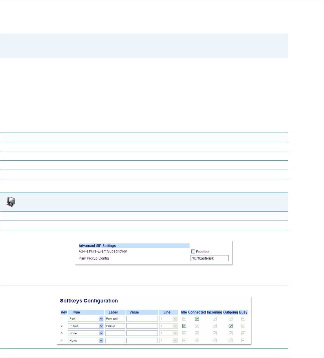
Operational Features
5-184 41-001343-02 REV04 – 05.2014
Configuring a Park/Pickup Key Using Aastra Web UI
For all phones and CT handsets, you first configure the park and pickup keys at Advanced Settings -> Line 1-N by enter-
ing the appropriate value based on the server in your network.
For 8/11-Line LCD phones and 6739i and 6867i phones, you can enter a key label and change the sofkey states at Opera-
tion->Softkeys and XML. The default state of the park configuration is "connected". The default state of the Pickup con-
figuration is "idle, outgoing".
For CT handsets, you can enter a key label at Operation->Handset Keys. If park or pickup are enabled on more than one
line on the base unit, the CT handsets use the first programmable configuration.
For example, if line 1 and line 6 are configured for park, the CT handsets use the configuration set for line 1 to park a call.
On 3-Line LCD phones, you can enter a key label at Operation->Softkeys and XML.
Park/Pickup Call Server Configuration Values
Use the following procedure to configure the park/pickup call feature using the Aastra Web UI.
Note:
Applicable values depend on the server in your network (Asterisk, BroadWorks, Sylantro, ININ). See the table below for
applicable values.
Server Park Values* Pickup Values*
Asterisk 70 70
Sylantro *98 *99
BroadWorks *68 *88
ININ PBX callpark pickup
Aastra Web UI
For 8/11-Line LCD Phones, 6739i, and 6867i
1. Click on Advanced Settings ->Line 1 (you can select any line)
2. Under Advanced SIP Settings in the “Park Pickup Config” field, enter the appropriate value based on the server in your network.
Notes:
•For values to enter in this field, see the table “Park/Pickup Call Server Configuration Values” on page5-182.
•Leave the park/pickup configuration field blank to disable the park and pickup feature.
3. Click on Operation->Softkeys and XML.
4. Pick a softkey to configure for parking a call.
5. In the "Type" field, select Park.
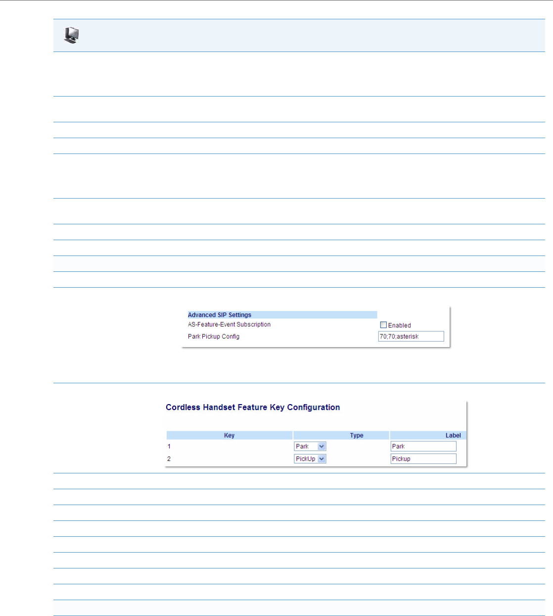
Operational Features
41-001343-02 REV04 – 05.2014 5-185
6. In the "Label" field, enter a label for the park softkey.
Note:
The” Value” and “Line” fields are already configured from the “Park Pickup Config” field.
7. The park softkey has a default state of “Connected”.
Leave this state enabled or to disable, uncheck the check box.
8. Pick a softkey to configure for Picking up a call.
9. In the "Type" field, select Pickup.
10. In the "Label" field, enter a label for the Pickup softkey.
Note:
The” Value” and “Line” fields are already configured from the “Park Pickup Config” field.
11. The pickup softkey has a default state of “Idle” and “Outgoing”.
Leave these states enabled or to disable, uncheck the check boxes.
12. Click Save Settings to save your changes.
13. Click on Reset, then click Restart to restart the IP phone and apply the changes.
For CT Handset:s
1. Click on Advanced Settings -> Line 1 (you can select any line)
2. Under Advanced SIP Settings in the “Park Pickup Config” field, enter the appropriate value based on the server in your network.
Notes:
•For values to enter in this field, see the table “Park/Pickup Call Server Configuration Values” on page5-182.
•Leave the park/pickup configuration field blank to disable the park and pickup feature.
3. Click on Operation->Handset Keys.
4. Pick a handset key to configure for parking a call.
5. In the "Type" field, select Park.
6. In the "Label" field, enter a label for the park softkey.
7. Pick another handset key to configure for picking up a call.
8. In the "Type" field, select Pickup.
9. In the "Label" field, enter a label for the pickup softkey.
10. Click Save Settings to save your changes.
11. Click on Reset, then click Restart to restart the IP phone and apply the changes.
For 3-Line LCD phones:
1. Click on Advanced Settings -> Line 1 (you can select any line)
Aastra Web UI
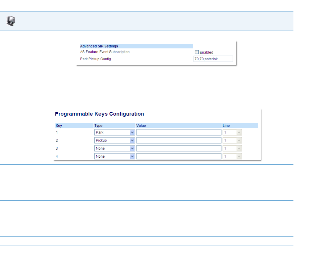
Operational Features
5-186 41-001343-02 REV04 – 05.2014
2. Under Advanced SIP Settings in the “Park Pickup Config” field, enter the appropriate value based on the server in your network.
Notes:
•For values to enter in this field, see the table “Park/Pickup Call Server Configuration Values” on page5-182.
•Leave the park/pickup configuration field blank to disable the park and pickup feature.
3. Click on Operation->Programmable Keys.
6731i Screen
4. Pick a key to configure for parking a call.
5. In the "Type" field, select Park.
Note:
The” Value” and “Line” fields are already configured from the “Park Pickup Config” field.
6. Pick a key to configure for picking up a call.
7. In the "Type" field, select Pickup.
Note:
The” Value” and “Line” fields are already configured from the “Park Pickup Config” field.
8. Click Save Settings to save your changes.
9. Click on Operation->Reset.
10. Click on Reset, then click Restart to restart the IP phone and apply the changes.
Aastra Web UI

Operational Features
41-001343-02 REV04 – 05.2014 5-187
Using the Park Call/Pickup Parked Call Feature
Use the following procedures on the IP phones to park a call and pick up a parked call.
Enhanced Park/Pickup Configuration Method (BroadSoft BroadWorks)
As mentioned above, Administrators have a choice between two methods of Park/Pickup configuration: static configura-
tion or programmable configuration. With the static configuration method, Administrators are required to define the
“sprecode” and “pickupsprecode” global configuration parameters (or alternatively define the “Park Call” and “Pickup
Parked Call” fields in the Aastra Web UI). By employing the static configuration method, the Park and Pickup keys are
automatically generated and displayed on the phone when the context presents itself (i.e. the Park key is presented during
an active call, and the Pickup key is presented when the call is parked). The benefit of this method is that individual Park
and Pickup keys do not have be defined. However, with this method, when the Park or Pickup key is pressed, the phone
seizes a secondary line to dial out using the Park or Pickup code.
With the programmable configuration method, Administrators are required to define the “sip park pickup config” (glo-
bal) or “sip lineN park pickup config” (per line) configuration parameter (or alternatively define the “Park Pickup Config”
field in the Aastra Web UI). By employing the programmable configuration method, individual Park and Pickup program-
IP Phone UI
Parking a Call
1. While on a live call, press the "Park" softkey.
2. Perform the following for your specific server:
If the call is parked successfully, the response is either a greeting voice confirming that the call was parked, or a hang up occurs. The parked
call party will get music on hold.
3. If the call fails, you can pick up the call (using the next procedure) and press the "Park" softkey again to retry step 2.
Picking up a Parked Call
4. Pick up the handset on the phone.
5. Enter the extension number where the call was parked.
6. Press the "Pickup" softkey.
If the call pick up is successful, you are connected with the parked call.
Notes:
•Applicable to the 9840i, 9840i CT, 6735i, 6737i, 6755i, 6757i, and 6757i CT IP phones only.
•This feature can only be configured for networks utilizing the BroadSoft BroadWorks call manager.
For Asterisk Server:
Server announces the extension number
where the call has been parked. Once the
call is parked, press the Goodbye key to
complete parking.
For BroadWorks Server:
After you hear the greeting from the Call-
Park server, enter the extension where
you want to park the call.
For Sylantro Server:
Enter the extension number where you
want to park the call, followed by "#" key.
For ININ PBX Server:
Enter the extension number where you
want to park the call, followed by "#" key.

Operational Features
5-188 41-001343-02 REV04 – 05.2014
mable keys/softkeys must be defined for the Park and Pickup keys to be displayed. However, the benefit of this method is
that the phone does not seize a secondary line to dial out the Park or Pickup code but instead utilizes a secondary call
appearance of the same line (i.e. a “hidden” or “virtual” line).
Administrators now can employ an enhanced method of configure park/pickup functionality for the 9840i, 9840i CT,
6735i, 6737i, 6755i, 6757i, and 6757i CT IP phones whereby the phone will automatically generate and display keys for
Park and Pickup functionality as per the static configuration method, but will use the SIP signalling behavior (i.e. a sec-
ondary call appearance of the same line) of the programmable configuration method.
This enhancement can be set using the configuration files by defining the “sprecode” and “pickupsprecode” parame-
ters in conjunction with the “sip park pickup config” (global) or “sip lineN park pickup config” (per line) configuration
parameters. For example:
sprecode: *68
pickupsprecode: *88
sip line1 park pickup config: *68;*88;broadworks
Predefining Dial Codes for Park/Pickup Programmable Configuration
Administrators can also predefine dial codes when configuring park/pickup functionality using the enhanced
park/pickup configuration method. Predefining dial codes can be useful for individuals (in scenarios where the
park/pickup extension is always be the same) or for deployments (in scenarios where all the extensions of the network
start with the same common leading numbers).
The configuration parameters “sip park pickup config” (global) and “sip lineN park pickup config” (per line) now sup-
port the following enhanced syntax:
sip (lineN) park pickup config: <park_code>,<park_dial_code>;
<pickup_code>,<pickup_dial_code>;broadworks
For example, if the parameter is defined as:
sip (lineN) park pickup config: *68,4200#;*88,4200#;broadworks
the dial code 4200# will be automatically dialed out after the *68 park code is sent and the user is connected to the park-
ing orbit. Additionally, 4200# will be automatically dialed out after the *88 pickup code is sent and the user is connected
to the pickup orbit.
Pauses can also be introduced to the dial code by adding commas whereby each comma equates to a 500ms pause. For
example, if the parameter is defined as:
sip (lineN) park pickup config: *68,,,,,4200#;*88,,,,,4200#;broadworks
a two-second pause will be introduced before the each of the 4200# dial codes is dialed out.
Use Case Scenario
Take, for example, a BroadSoft BroadWorks-managed call network where the park/pickup extensions all start with the
first two digits 4 and 2 and the last two digits have a range from 00 to 99. Administrators can define the “sip park pickup
config” parameter as:
sip park pickup config: *68,,,,,,,,,42;*88,,,,,,,,,42;broadworks
When a user is in an active call and presses the Park softkey, the active call will be placed on hold, the phone will dial *68
to connect to the parking orbit, wait four seconds (so that the user can hear the parking announcement from the call
manager), automatically send the park dial code of 42, and then at this time the user can enter the last two digits of the
parking extension to complete the call park.
When the user presses the Pickup softkey, the phone will dial out *88 to connect to the pickup orbit, wait four seconds,
automatically send the pickup dial code of 42, and then at this time the user can enter the last two digits of the pickup
extension to complete the call pickup.
Notes:
•To set the enhancement using the Aastra Web UI the “Park Call” and “Pickup Parked Call” along with the “Park
Pickup Config” fields must be defined.
•Programmable keys/softkeys do not need to be configured when utilizing this enhanced configuration method.
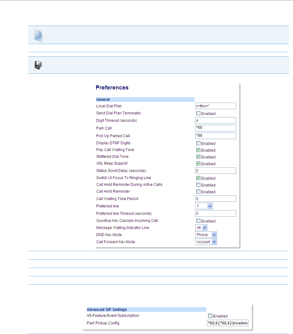
Operational Features
41-001343-02 REV04 – 05.2014 5-189
Enabling Enhanced Park/Pickup Configuration Method (for BroadSoft BroadWorks only)
Use the following procedure to enable the enhanced park/pickup method on the IP Phones.
Configuration Files
For specific parameters you can set in the configuration files, see Appendix A, the section,“Park and Pickup Settings” on pageA-154.
Aastra Web UI
1. Click on Basic Settings ->Preferences ->General
2. Enter the park code in the Park Call field to which active calls will be parked (e.g. *68 for BroadSoft BroadWorks).
3. Enter the pickup code in the Pick Up Parked Call field (e.g. *88 for BroadSoft BroadWorks).
4. Click Save Settings to save your changes.
5. Click on Advanced Settings ->Global SIP (or Line #).
6. Under Advanced SIP Settings in the “Park Pickup Config” field enter in the appropriate values based on the following syntax:
<park_code>,<park_dial_code>;
<pickup_code>,<pickup_dial_code>;broadworks
7. Click Save Settings to save your changes.
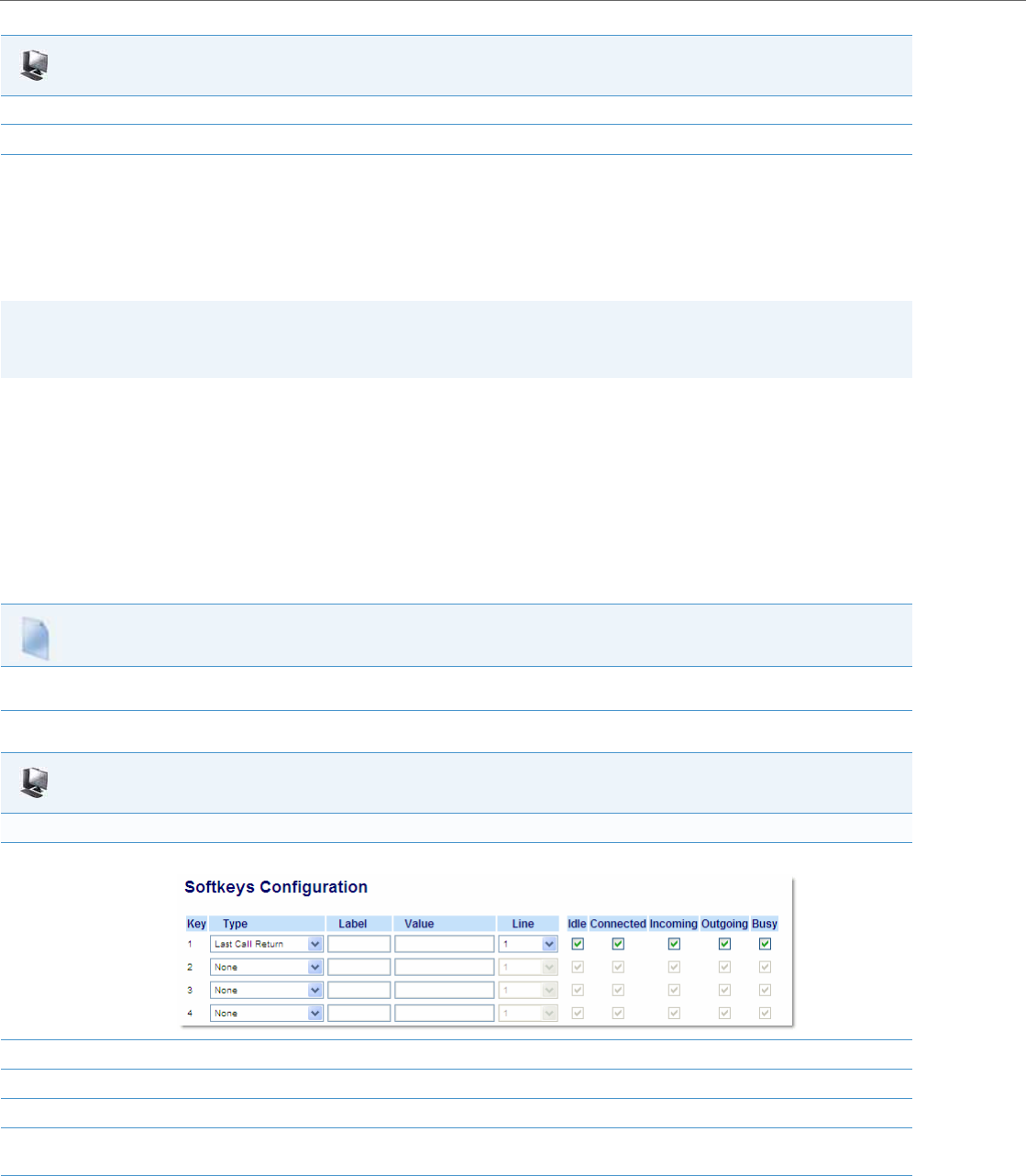
Operational Features
5-190 41-001343-02 REV04 – 05.2014
Last Call Return (lcr) (Sylantro Servers)
Last call return (lcr) allows an administrator or user to configure a "last call return" function on a softkey or programma-
ble key. This feature is for Sylantro servers only.
You can configure the “lcr” softkey feature via the configuration files or the Aastra Web UI.
How it works
If you configure "lcr" on a softkey or programmable key, and a call comes into your phone, after you are finished with the
call and hangup, you can press the key configured for “lcr” and the phone dials the last call you received. When you con-
figure an “lcr” softkey, the label “LCR” displays next to that softkey on the IP phone. When the Sylantro server detects an
“lcr” request, it translates this request and routes the call to the last caller.
Configuring Last Call Return
Use the following procedures to configure LCR on the IP phones.
8. Click on Operation->Reset
9. Click on Restart to restart the IP phone and apply the changes.
Note:
On the 6739i, you can configure a Last Call Return softkey using the IP Phone UI also. For more information, see the Aas-
tra Model 6739i IP Phone User Guide.
Configuration Files
For specific last call return (lcr) parameters you can set in the configuration files, see Appendix A, the section, “Softkey/Programmable Key/Keypad
Key/Feature Key/Expansion Module Key/Hard Key Parameters” on pageA-156.
Aastra Web UI
For the 6755i & 6757i/6757i CT:
1. Click on Operation->Softkeys and XML.
2. Pick a softkey to configure for Last Call Return.
3. In the "Type" field, select Last Call Return.
4. In the "Line" field, select a line for which to apply the last call return configuration.
5. The lcr softkey has a default state of “Idle”, “ Connected”, “Incoming”, “Outgoing”.
Leave these states enabled or to disable, uncheck the check boxes as required.
6. Click Save Settings to save your changes.
Aastra Web UI
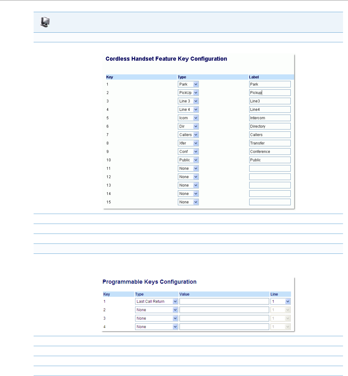
Operational Features
41-001343-02 REV04 – 05.2014 5-191
For the 6757i CT Handset:
1. Click on Operation->Handset Keys.
2. Pick a handset key to configure for Last Call Return.
3. In the "Key Function" field, select Last Call Return.
4. Click Save Settings to save your changes.
For 3-Line LCD phones:
1. Click on Operation->Programmable Keys.
6753i Screen
2. Pick a key to configure for Last Call Return.
3. In the "Type" field, select Last Call Return.
4. In the "Line" field, select a line for which to apply the lcr configuration.
5. Click Save Settings to save your changes.
Aastra Web UI

Operational Features
5-192 41-001343-02 REV04 – 05.2014
Call Forwarding
Call Forward (CFWD) on the IP phone allows incoming calls to be forwarded to another destination. The phone sends the
SIP message to the SIP proxy, which then forwards the call to the assigned destination.
An Administrator or User can configure CFWD on the phone-side by setting a mode for the phone to use (Account,
Phone, or Custom). Once the mode is set, you can use the IP Phone UI to use the CFWD feature at Options->Call Forward
or by pressing a configured Call Forward softkey/programmable key/extension module key.
The following describes the behavior for each CFWD mode.
•Account mode - The account mode allows you to configure CFWD on a per account basis. Pressing a configured
CFWD key applies to the account in focus.
•Phone mode - The Phone mode allows you to set the same CFWD configuration for all accounts (All, Busy, and/or No
Answer). When you configure the initial account, the phone applies the configuration to all other accounts. (In the
Aastra Web UI, only the account you configured is enabled. All other accounts are grayed out but set to the same con-
figuration.) Using the Aastra Web UI, if you make changes to that initial account, the changes apply to all accounts on
the phone.
•Custom mode - The Custom mode allows you to configure CFWD for a specific account or all accounts. You can con-
figure a specific mode (All, Busy, and/or No Answer) for each account independently or all accounts. On 3-Line LCD
phones and the 6867i, you can set all accounts to ALL On or ALL Off. On the 8 and 11-Line LCD phones and the 6739i,
you can set all accounts to All On, All Off, or copy the configuration for the account in focus to all other accounts
using a CopytoAll softkey.
You can enable different call forwarding rules/modes independently (for example, you can set different phone numbers
for Busy, All, and NoAns modes and then turn them on/off individually).
The following table describes the key and Message Waiting Indicator (MWI) LEDs when you enable CFWD on the IP
Phone.
You can enable/disable CFWD and set a CFWD key using the configuration files or the Aastra Web UI. You can set CFWD
mode (Account, Phone, Custom) using the configuration files, Aastra Web UI or IP Phone UI.
Important Notes
•In the configuration files, the “call forward key mode” parameter in the section, “Configuring Call Forwarding” on
page5-191 is in addition to the previous call forward parameter (call forward disabled). You can still use the previous
call forwarding parameter if desired in the configuration files.
•In the IP Phone UI, you can access the Call Forwarding features at the path Options->Call Forward or by pressing a con-
figured CFWD key.
•If you make changes to the configuration for CFWD via the IP Phone UI, you must refresh the Aastra Web UI screen to
see the changes.
Note:
If there is only one account configured on the phone, then the mode setting is ignored and the phone behaves as if the
mode was set to “Phone”.
Key LED Behavior for All Modes MWI LED Behavior for All Modes
CFWD key LED RED if any CFWD mode is enabled for the account in
focus.
CFWD key LED OFF if all CFWD modes are disabled for the account in
focus.
MWI LED ON if any CFWD mode is enabled for the account in focus.
MWI LED OFF if all CFWD modes are disabled for the account in focus.
Note:
On the 6739i, you can configure a Call Forward softkey using the IP Phone UI also. For more information, see the Aastra
Model 6739i IP Phone User Guide.
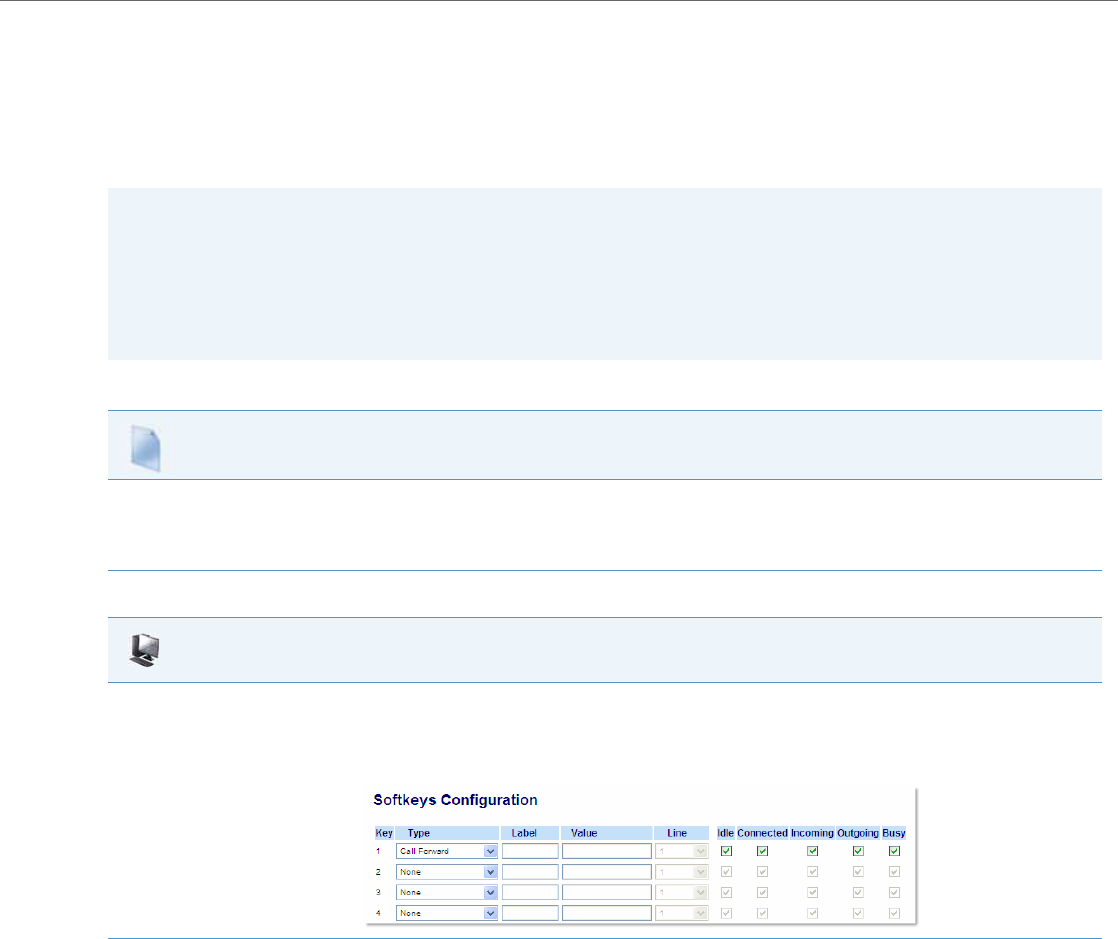
Operational Features
41-001343-02 REV04 – 05.2014 5-193
Configuring Call Forwarding
You use the following parameters to set CFWD on the IP Phone using the configuration files:
•call forward key mode
•softkeyN type, topsoftkeyN type, prgkeyN type, or expmodX keyN type
•softkeyN states (optional)
Use the following procedures to configure Call Forwarding on the IP phones.
Notes:
•If there is no CFWD key configured on the phone or it is removed, you can still set the CFWD modes via the IP Phone
UI at the path Options->Call Forward.
•If there is only one account configured on the phone, then the mode setting is ignored and the phone behaves as if
the mode was set to “Phone”.
•When configuring a CFWD mode (All, Busy, No Answer) for an account, you must configure a CFWD number for that
mode in order for the mode to be enabled.
Configuration Files
For specific call forwarding parameters you can set in the configuration files, see Appendix A, the sections,
•“Call Forward Settings” on pageA-110.
•“Call Forward Key Mode Settings” on pageA-111.
•“Softkey/Programmable Key/Keypad Key/Feature Key/Expansion Module Key/Hard Key Parameters” on pageA-156.
Aastra Web UI
1. Click on Operation->Softkeys and XML;
or
Click on Operation->Programmable Keys;
or
Click on Operation->Expansion Module.
2. Click Save Settings to save your changes.
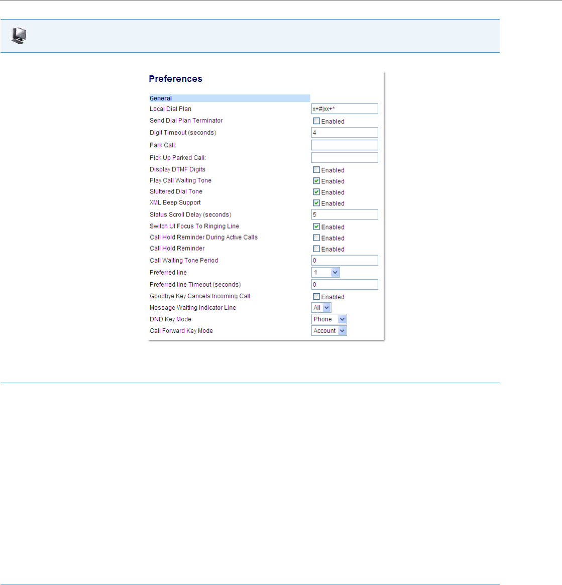
Operational Features
5-194 41-001343-02 REV04 – 05.2014
3. Click on Basic Settings->Preferences->General.
Note:
If there is no CFWD key configured on the phone or it is removed, you can still set the CFWD modes via the IP Phone UI at the path Options-
>Call Forward.
4. In the “Call Forward Key Mode” field, select a call forward mode to use on the phone.
Valid values are: Account, Phone, Custom. Default is Account.
•Account
The account mode allows you to configure CFWD on a per account basis. Pressing a configured CFWD key applies to the account in focus.
•Phone
The Phone mode allows you to set the same CFWD configuration for all accounts (All, Busy, and/or No Answer). When you configure the
initial account, the phone applies the configuration to all other accounts. (In the Aastra Web UI, only the account you configured is ena-
bled. All other accounts are grayed out but set to the same configuration.) Using the Aastra Web UI, if you make changes to that initial
account, the changes apply to all accounts on the phone.
•Custom
The Custom mode allows you to configure CFWD for a specific account or all accounts. You can configure a specific state (All, Busy, and/or
No Answer) for each account independently or all accounts. On 3-Line LCD phones, you can set all accounts to ALL On or ALL Off. On the
8 and 11-Line LCD phones, you can set all accounts to All On, All Off, or copy the configuration for the account in focus to all other
accounts using a CopytoAll softkey.
Notes:
•If there is no CFWD key configured on the phone or it is removed, you can still set the CFWD modes via the IP Phone UI at the path Options-
>Call Forward.
•If there is only one account configured on the phone, then the mode setting is ignored and the phone behaves as if the mode was set to
“Phone”.
•When configuring a CFWD state (All, Busy, No Answer) for an account, you must configure a CFWD number for that state in order for the
state to be enabled.
5. Click Save Settings to save your changes.
The change takes effect immediately without a reboot.
Aastra Web UI
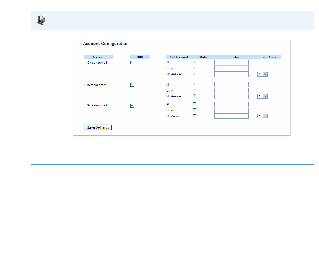
Operational Features
41-001343-02 REV04 – 05.2014 5-195
6. Click on Basic Settings->Account Configuration.
Note:
If the BroadSoft BroadWorks Executive and Assistant Services feature is enabled and your phone is configured with the Assistant’s role, an
additional Forward Filtering option may be available on the Account Configuration page. For information on the BroadWorks Executive and
Assistant Services feature, refer to BroadSoft BroadWorks Executive and Assistant Services Feature on page 6-44. For details on how to con-
figure and utilize Forward Filtering, please refer to the respective phone model’s Aastra SIP IP Phone User Guide.
7. For each account, enable CFWD state by placing a check mark in one or more of the following “State” fields:
•All
•Busy
•No Answer
The “All” option forwards all incoming calls for this account to the specified phone number regardless of the state of the phone. The phone
can be in the Busy or No Answer states, or can be in the idle state. The phone still forwards all calls to the specified number.
The “Busy” option call forwards incoming calls only if the account is in the busy state. The calls are forwarded to the specified phone number.
The “No Answer” option call forwards incoming calls only if the account rings but is not answered in the defined number of rings. The call
gets forwarded to the specified number.
Note:
You can use the “Busy” and “No Answer” states together using different forwarding phone numbers. If these states are enabled for an
account (the “All” state is disabled), and the phone is in the busy state when a call comes in, the phone can forward the call to the specified
phone number (for example, voicemail). If there is no answer on the phone after the specified number of rings, the phone can forward the
call to a different specified number, such as a cell phone number.
8. For each account, in the “Number” field, enter the phone number for which you want the incoming calls to forward to if the phone is in the
specified state.
If using the “Account” mode or “Custom” mode, you can enter different phone numbers for each account.
Notes:
•If you selected “Account” mode in step 4, you can enable/disable each account or all accounts as applicable. You can enter different phone
number for each enabled state.
If you selected “Custom” mode, you can enable/disable each account or all accounts as applicable. You can enter different phone numbers
for each enabled state.
If you selected “Phone” mode, all accounts are set to the same CFWD configuration (All, Busy, and/or No Answer) as Account 1 on the
phone. (In the Aastra Web UI, only Account 1 is enabled. All other accounts are grayed out but use the same configuration as Account 1.)
Using the Aastra Web UI, if you make changes to Account 1, the changes apply to all accounts on the phone. Using the IP Phone UI, if you
make changes to any other account other then Account 1, the changes also apply to all accounts on the phone. When enabling a CFWD
state, you must specify a phone number for the phone to CFWD to. The number you specify applies to all accounts of the same mode.
•Number and name of accounts that display to this screen are dependant on the number and name of accounts configured on the phone.
In the screen in step 6, Screenname1 is configured on Line 1, Screenname2 is configured on Line 2, and Screenname3 is configured on Line
3. The name for the account is dependant on the name specified for the “Screen Name” parameter at the path Advanced Settings->LineN.
If you do not specify a value for the “Screen Name” parameter, the account name is based on the “Phone Number” parameter at the path
Advanced Settings->LineN. If neither the “Screen Name” nor the “Phone Number” parameters are specified, the account name shows “1”, “2”,
“3”, etc. only.
Aastra Web UI

Operational Features
5-196 41-001343-02 REV04 – 05.2014
Configuring CFWD via the IP Phone UI (3-Line Phones)
Once CFWD is enabled on your phone, you can access and change the configuration using the IP phone UI or the Aastra
Web UI. You can access the CFWD menus by pressing a pre-configured CFWD key, or by selecting Options > Call Forward
from the IP phone UI.
9. For the No Answer state, in the “No. Rings” field, enter the number of times that the account rings before forwarding the call to the specified
number. Valid values are 1 through 20. Default is 1.
Note:
When using the “Account” mode or “Custom” mode, you can enter a different number of rings for each account. If you use the Aastra Web
UI to change the Call Forward Key Mode to “Phone”, all accounts synchronize to Account 1.
10. Click Save Settings to save your changes.
The change takes effect immediately without a reboot.
Notes:
•If there is no CFWD key configured on the phone or it is removed, you can still enable CFWD via the at the path
Options->Call Forward.
•If there is only one account configured on the phone, then the mode setting is ignored and the phone behaves as if
the mode was set to “Phone”.
•Using the Aastra Web UI, if you change the CFWD key mode to “Phone”, all accounts synchronize to the current set-
ting of Account 1.
•If the BroadSoft BroadWorks Executive and Assistant Services feature is enabled and your phone is configured with
the Assistant’s role, an additional Forward Filtering option may be available on the CFWD Mode menu. For informa-
tion on the BroadWorks Executive and Assistant Services feature, refer to BroadSoft BroadWorks Executive and Assistant
Services Feature on page 6-44. For details on how to configure and utilize Forward Filtering, please refer to the respec-
tive phone model’s Aastra SIP IP Phone User Guide.
Aastra Web UI
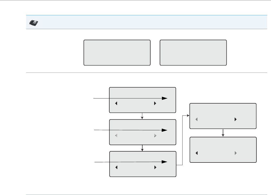
Operational Features
41-001343-02 REV04 – 05.2014 5-197
CFWD in Account Mode
IP Phone UI
1. Use the 3 and 4 navigation keys to scroll through each account.
In the above example, account 1 has CFWD All enabled and account 2 has CFWD Busy enabled.
2. Press the programmed Call Forward key. The Call Forward Mode screen displays. Use the 2 and 5 navigation keys to scroll through each
state type.
In the above example, CFWD All is enabled as indicated by a check mark (), CFWD Busy is enabled but no call forward phone number con-
figured as indicated by a !, and CFWD No Answer is disabled, as indicated by an X.
3. Select a state for the account(s) in focus using the 2 and 5 navigation keys.
You can enable/disable any or all of the following states for an account:
•All: Forwards all incoming calls for the respective account to the specified number.
•Busy: Forwards incoming calls to a specified number if DND has been enabled for that account OR if the account is currently engaged in
another call.
•No Answer: Forwards incoming calls to a specified number if the call has not been answered for the specified number of rings.
Note:
If CFWD All, CFWD Busy, and CFWD No Answer are all enabled (and/or if the account has DND enabled), the CFWD All settings take prece-
dence over CFWD Busy and CFWD No Answer.
You can also use the following keys if required:
•All Off: Disables all CFWD states for the current account in focus
•All On: Enables all CFWD states for the current account in focus
John Smith
CFWD All
Tue Aug 20 2:55pm
L1 J. Smith
CFWD Busy
Tue Aug 20 2:55pm
L2
Cfwd Mode
1. All
Done Change
Cfwd Mode
2. Busy !
Done Change
Cfwd Mode
3. No Answer X
Done Change
Cfwd Mode
4. All Off
Done Change
Cfwd Mode
5. All On
Done Change
Indicates
Indicates
CFWD Enabled
CFWD Disabled
Indicates
no CFWD
phone number
configured
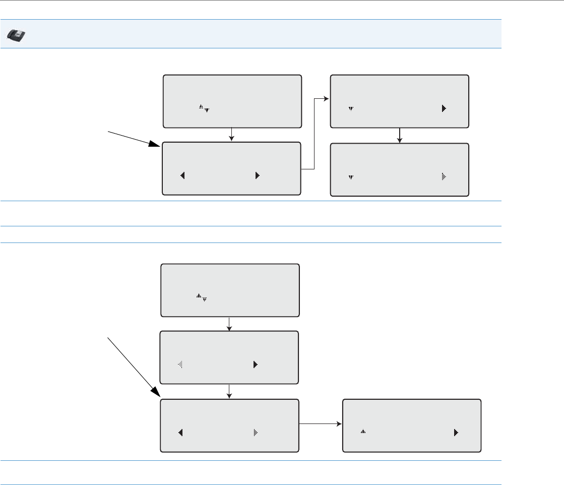
Operational Features
5-198 41-001343-02 REV04 – 05.2014
4. Press the 4 Change navigation key for the state you selected in Step 3. Scroll to the CFWD State screen. This displays the current state of the
mode you selected. In the following example, the CFWD All state is ON.
5. Press the 4Change navigation key in the CFWD State screen. Press 2 to toggle the state of the CFWD mode ON or OFF. In the example in
Step 4, you press 2 to change the option to OFF.
6. Press 4Set to save the change.
7. In the CFWD State screen, press the 2 navigation keys to scroll to the CFWD Number screen and press 4Change.
8. Enter a phone number to apply to the current state in focus. When the phone is in the state you specified, and a call comes into the phone,
it forwards the call to the number you specify.
9. Press 4Set to save the change.
IP Phone UI
CFWD State Screen
Cfwd All
Use to view
Cfwd State
On
Done Change
1
Cfwd State
ON
Next Set
Cfwd State
OFF
Next Set
Change
CFWD Number Screen
Cfwd All
Use to view
Cfwd State
On
Done Change
1
Cfwd Number
5555_
Cancel Set
Cfwd Number
5555
Done Change
2Change
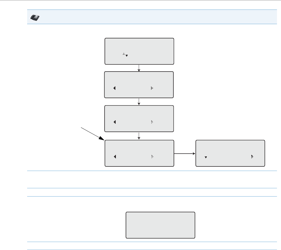
Operational Features
41-001343-02 REV04 – 05.2014 5-199
10. For the CFWD No Answer state, In the CFWD Number screen, press the 2 navigation key to scroll to the CFWD No. Rings screen and press
4Change.
11. Press 2Next to select the number of rings to apply to the phone for call forwarding incoming calls. Valid values are 1 to 20. Default is 3.
When the phone receives an incoming call, and call forward is configured on the phone, the phone rings the number of times you specify
in the No. Rings screen, and then forwards the call if there is no answer.
12. Press 4Set to save the change.
13. Press 3Done to save all your changes.
Each time you press 3 Done, the following screen displays.
14. Press # Confirm to confirm the change(s) each time the Apply Changes screen displays. All changes are saved to the phone.
IP Phone UI
CFWD No. Rings Screen
Cfwd NoAnswer
Use to view
Cfwd State
On
Done Change
1
Cfwd Number
Done Change
2
No. Rings
3
Next Set
Change
No. Rings
3
Done Change
3
Apply Changes
0Cancel
#Confirm
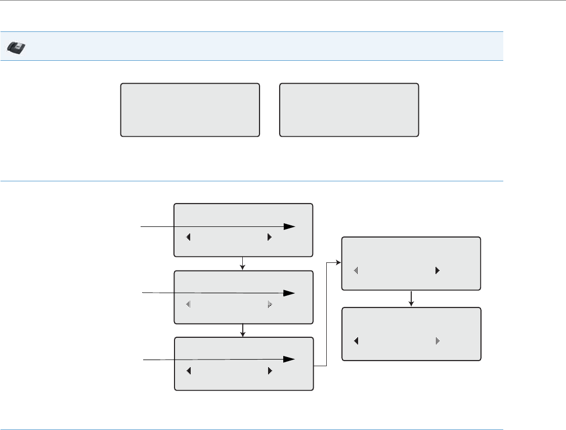
Operational Features
5-200 41-001343-02 REV04 – 05.2014
CFWD in Phone Mode
IP Phone UI
1. Use the 3 and 4 navigation keys to scroll through each account.
In the above example, account 1 and account 2 are the accounts configured on the phone. Both accounts have CFWD enabled as indicated
by the CFWD All message.
Note:
In Phone mode, when you change the call forward configuration for an account, the change applies to all accounts.
2. Press the Call Forward key. The Call Forward menu displays. Use the 2 and 5 navigation keys to scroll through each state type.
In the above example, CFWD All is enabled as indicated by a check mark (), CFWD Busy is enabled but no call forward phone number con-
figured as indicated by a !, and CFWD No Answer is disabled, as indicated by an X.
3. Select a state using the 2 and 5 navigation keys.
You can enable/disable a specific account on the phone with any or all of the following states. However, the configuration you set will apply
to all accounts on the phone.
•All: Forwards all incoming calls for the respective account to the specified number.
•Busy: Forwards incoming calls to a specified number if DND has been enabled for that account OR if the account is currently engaged in
another call.
•No Answer: Forwards incoming calls to a specified number if the call has not been answered for the specified number of rings.
Note:
If CFWD All, CFWD Busy, and CFWD No Answer are all enabled (and/or if the account has DND enabled), the CFWD All settings take prece-
dence over CFWD Busy and CFWD No Answer.
You can also use the following keys if required:
•All Off: Disables all CFWD states for the current account in focus
•All On: Enables all CFWD states for the current account in focus
Note:
In Phone mode, the initial configuration you set for an account applies to all the accounts on the phone.
John Smith
CFWD All
Tue Aug 20 2:55pm
L1 J. Smith
CFWD All
Tue Aug 20 2:55pm
L2
Cfwd Mode
1. All
Done Change
Cfwd Mode
2. Busy !
Done Change
Cfwd Mode
3. No Answer X
Done Change
Cfwd Mode
4. All Off
Done Change
Cfwd Mode
5. All On
Done Change
Indicates
Indicates
CFWD Enabled
CFWD Disabled
Indicates
no CFWD
phone number
configured
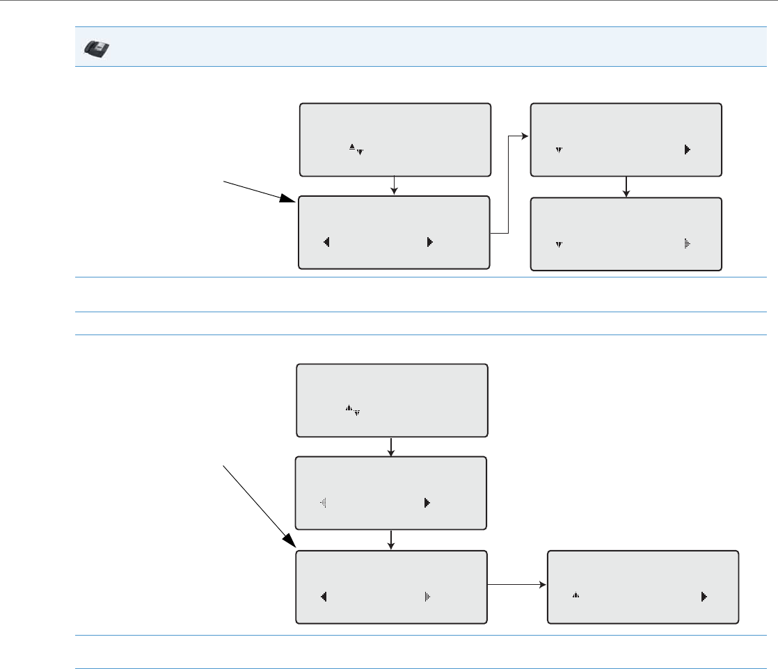
Operational Features
41-001343-02 REV04 – 05.2014 5-201
4. Press the 4Change key for the mode you selected in Step 2. Scroll to the CFWD State screen. This screen displays the current state of the
mode you selected. In the following example, the CFWD All state is ON.
5. Press the 4Change key in the CFWD State screen. Press 2Next to toggle the state of the CFWD state ON or OFF. In the example in Step 4,
you press 2Next to change the option to Off.
6. Press the 4Set key to save the change.
7. In the CFWD State screen, press the 2 navigation key to scroll to the CFWD Number screen and press 4Change.
8. Enter a phone number to apply to the current state in focus. When the phone is in the state you specified, and a call comes into the phone,
it forwards the call to the number you specify.
9. Press 4Set to save the change.
IP Phone UI
CFWD State Screen
Cfwd All
Use to view
Cfwd State
On
Done Change
1
Cfwd State
ON
Next Set
Cfwd State
OFF
Next Set
Change
CFWD Number Screen
Cfwd All
Use to view
Cfwd State
On
Done Change
1
Cfwd Number
5555_
Cancel Set
Cfwd Number
5555
Done Change
2Change
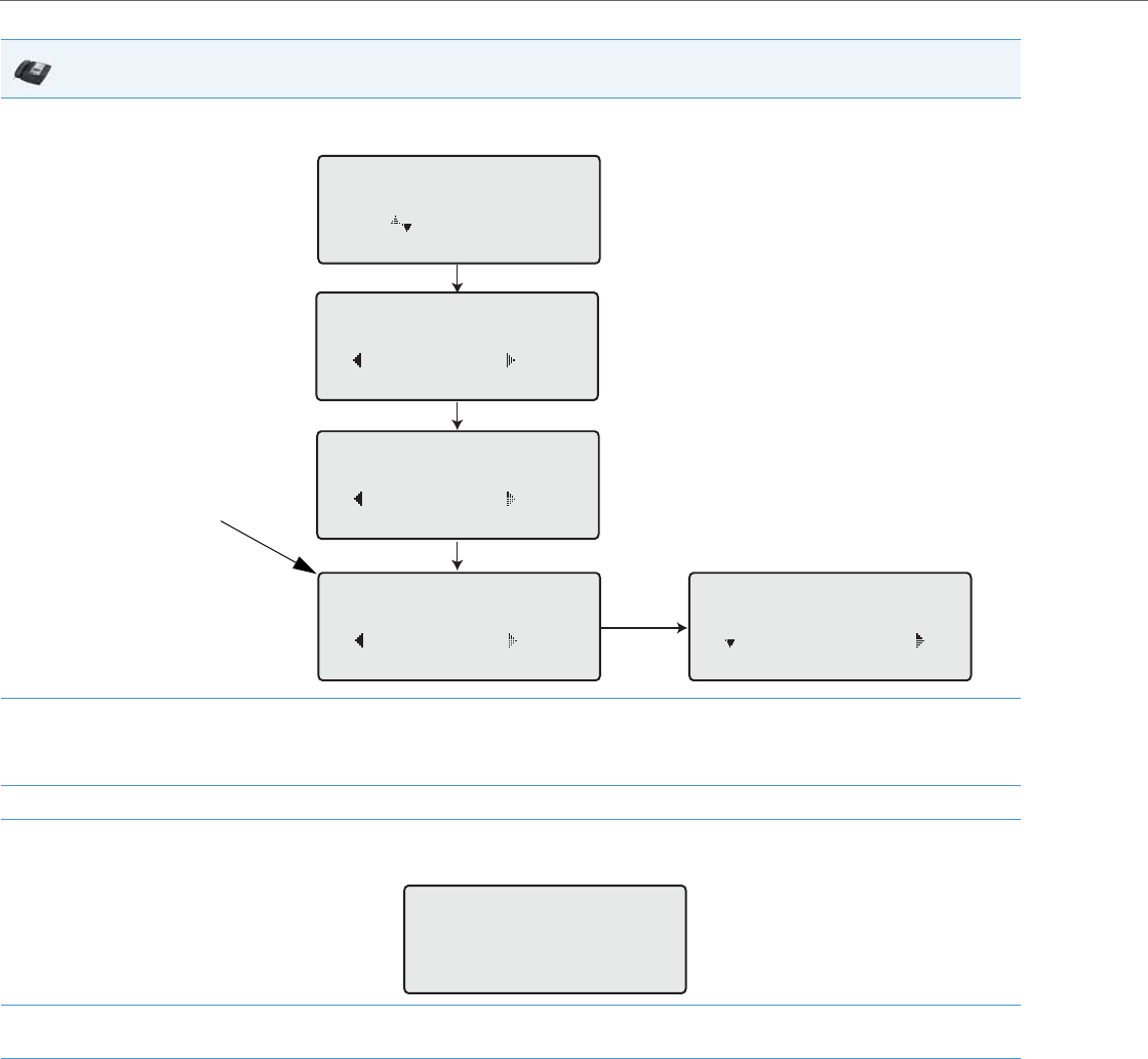
Operational Features
5-202 41-001343-02 REV04 – 05.2014
10. For the CFWD No Answer state, in the CFWD Number screen, press the 2 navigation key to scroll to the CFWD No. Rings screen and press
4Change.
11. Press the 2Next key to select the number of rings to apply to the phone for call forwarding incoming calls. Valid values are 1 to 20. Default
is 3.
When the phone receives an incoming call, and call forward is configured on the phone, the phone rings the number of times you specify
in the No. Rings screen, and then forwards the call.
12. Press 4Set to save the change.
13. Press 3Done to save all your changes.
Each time you press 3Done, the following screen displays.
14. Press # Confirm to confirm the change(s) each time the Apply Changes screen displays.
All the same changes are saved to all accounts on the phone.
IP Phone UI
CFWD No. Rings Screen
Cfwd NoAnswer
Use to view
Cfwd State
On
Done Change
1
Cfwd Number
Done Change
2
No. Rings
3
Next Set
Change
No. Rings
3
Done Change
3
Apply Changes
0Cancel
#Confirm
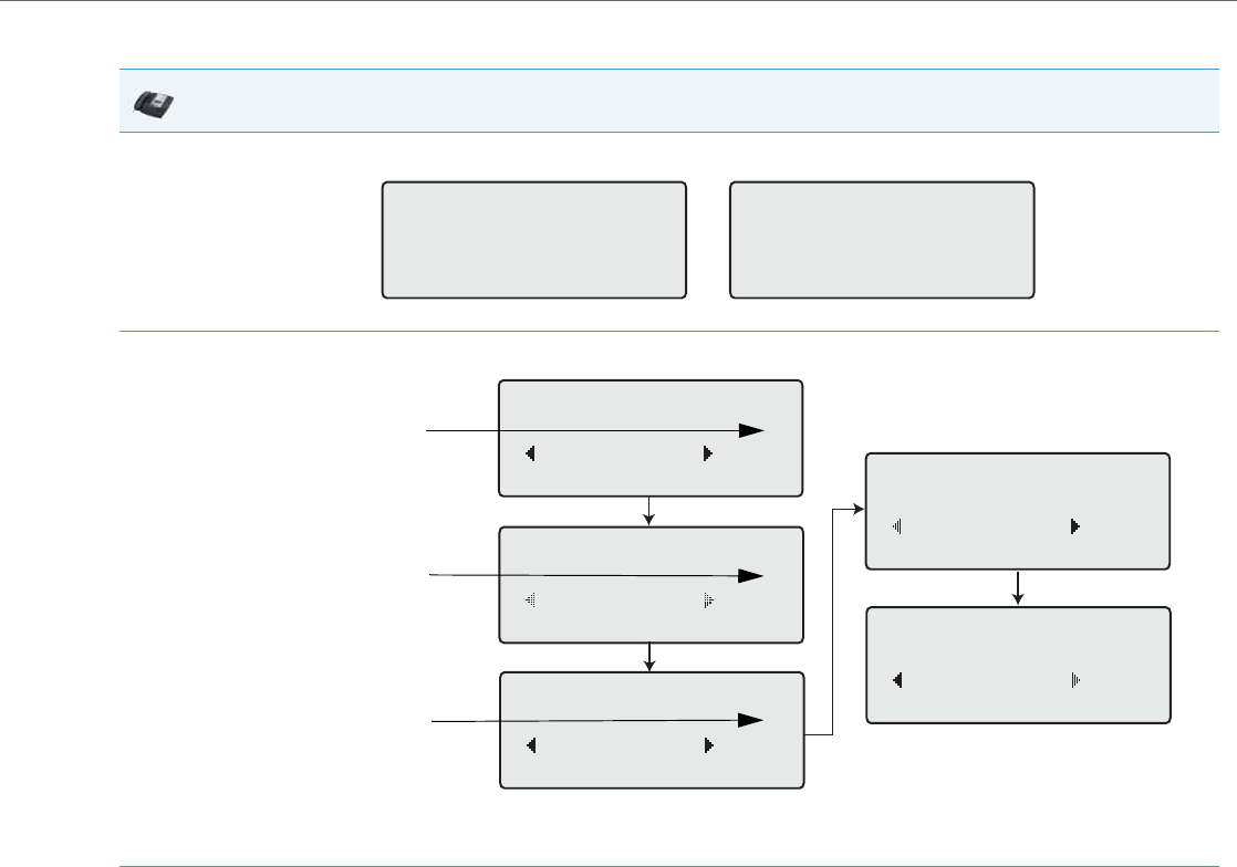
Operational Features
41-001343-02 REV04 – 05.2014 5-203
CFWD in Custom Mode
IP Phone UI
1. Use the 3 and 4 navigation keys to scroll through each account.
In the above example, account 1 has CFWD All enabled and account 2 has CFWD Busy enabled.
2. Press the Call Forward key. The Call Forward menu displays. Use the 2 and 5 navigation keys to scroll through each state type.
In the above example, CFWD All is enabled as indicated by a check mark (), CFWD Busy is enabled but no call forward phone number con-
figured as indicated by a !, and CFWD No Answer is disabled, as indicated by an X.
3. Select a state for the account(s) in focus using the 2 and 5 navigation keys.
You can enable/disable any or all of the following states for a specific account or for all accounts (with individual configurations):
•All: Forwards all incoming calls for the respective account to the specified number.
•Busy: Forwards incoming calls to a specified number if DND has been enabled for that account OR if the account is currently engaged in
another call.
•No Answer: Forwards incoming calls to a specified number if the call has not been answered for the specified number of rings.
Note:
If CFWD All, CFWD Busy, and CFWD No Answer are all enabled (and/or if the account has DND enabled), the CFWD All settings take prece-
dence over CFWD Busy and CFWD No Answer.
You can also use the following keys if required:
•All Off: Disables all CFWD states for the current account in focus
•All On: Enables all CFWD states for the current account in focus
John Smith
CFWD All
Tue Aug 20 2:55pm
L1 J. Smith
CFWD Busy
Tue Aug 20 2:55pm
L2
Cfwd Mode
1. All
Done Change
Cfwd Mode
2. Busy !
Done Change
Cfwd Mode
3. No Answer X
Done Change
Cfwd Mode
4. All Off
Done Change
Cfwd Mode
5. All On
Done Change
Indicates
Indicates
CFWD Enabled
CFWD Disabled
Indicates
no CFWD
phone number
configured

Operational Features
5-204 41-001343-02 REV04 – 05.2014
4. Press the 4Change key for the mode you selected in step 2. Scroll to the CFWD State screen. This displays the current state of the mode you
selected. In the following example, the CFWD All state is ON.
5. Press the 4Change key in the CFWD State screen. Press 2Next to toggle the state of the CFWD state ON or OFF. In the example in Step 4,
you press 2Next to change the option to Off.
6. Press the 4Set key to save the change.
7. In the CFWD State screen, press the 2 navigation key to scroll to the CFWD Number screen and press 4Change.
8. Enter a phone number to apply to the current state in focus. When the phone is in the state you specified, and a call comes into the phone,
it forwards the call to the number you specify.
9. Press 4Set to save the change.
IP Phone UI
CFWD State Screen
Cfwd All
Use to view
Cfwd State
On
Done Change
1
Cfwd State
ON
Next Set
Cfwd State
OFF
Next Set
Change
CFWD Number Screen
Cfwd All
Use to view
Cfwd State
On
Done Change
1
Cfwd Number
5555_
Cancel Set
Cfwd Number
5555
Done Change
2Change
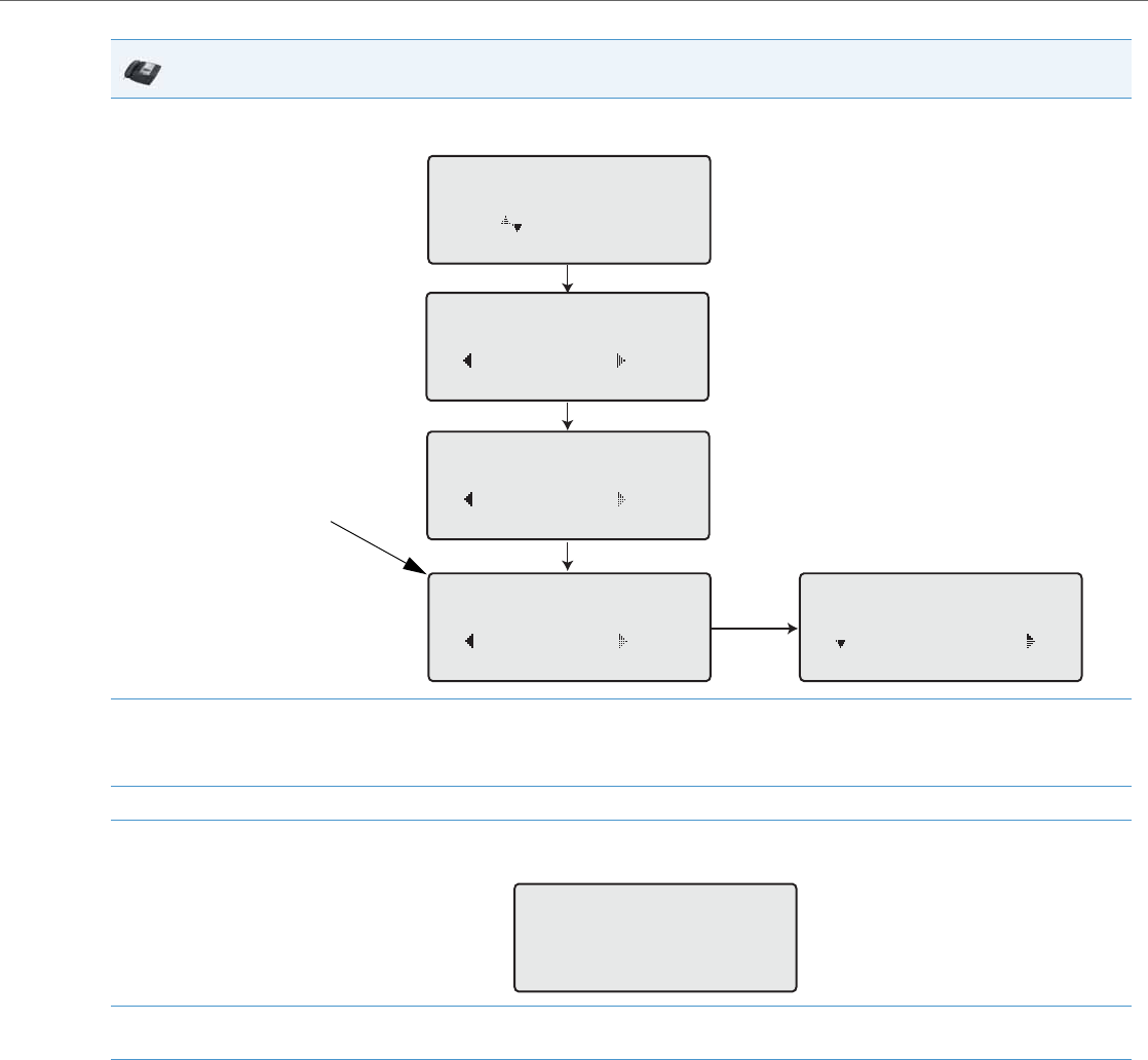
Operational Features
41-001343-02 REV04 – 05.2014 5-205
10. For the CFWD No Answer state, in the CFWD Number screen, press the 2 navigation key to scroll to the CFWD No. Rings screen and press
4Change.
11. Press the 2Next key to select the number of rings to apply to the phone for call forwarding incoming calls. Valid values are 1 to 20. Default
is 3.
When the phone receives an incoming call, and call forward is configured on the phone, the phone rings the number of times you specify
in the No. Rings screen, and then forwards the call.
12. Press 4Set to save the change.
13. Press 3Done to save all your changes.
Each time you press3 Done, the following screen displays.
14. Press # Confirm to confirm the change(s) each time the Apply Changes screen displays.
All changes are saved to the phone for all accounts.
IP Phone UI
CFWD No. Rings Screen
Cfwd NoAnswer
Use to view
Cfwd State
On
Done Change
1
Cfwd Number
Done Change
2
No. Rings
3
Next Set
Change
No. Rings
3
Done Change
3
Apply Changes
0Cancel
#Confirm

Operational Features
5-206 41-001343-02 REV04 – 05.2014
Using CFWD via the IP Phone UI (8-Line and 11-Line Phones)
Once CFWD is enabled on your phone, you can access and change the configuration using the IP Phone UI or the Aastra
Web UI. You can access the CFWD menus by pressing a pre-configured Call Forward key, or by selecting Options->Call
Forward from the IP Phone UI.
The following procedure assumes you have already configured a CFWD key AND assumes there are three accounts con-
figured on the phone.
Notes:
•If there is no CFWD key configured on the phone or it is removed, you can still enable CFWD via the at the path
Options->Call Forward.
•If there is only one account configured on the phone, then the mode setting is ignored and the phone behaves as if
the mode was set to “Phone”.
•Using the Aastra Web UI, if you change the CFWD key mode to “Phone”, all accounts synchronize to the current set-
ting of Account 1.
•If the BroadSoft BroadWorks Executive and Assistant Services feature is enabled and your phone is configured with
the Assistant’s role, an additional Forward Filtering option may be available on the CFWD Mode menu. For informa-
tion on the BroadWorks Executive and Assistant Services feature, refer to BroadSoft BroadWorks Executive and Assistant
Services Feature on page 6-44. For details on how to configure and utilize Forward Filtering, please refer to the respec-
tive phone model’s Aastra SIP IP Phone User Guide.
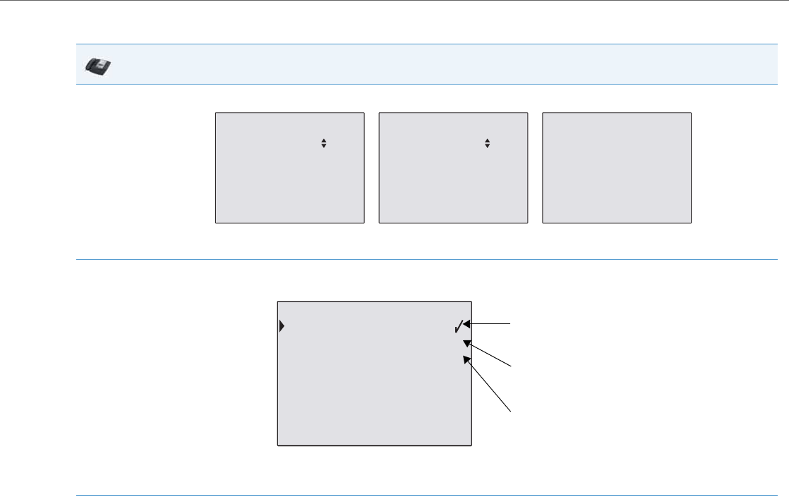
Operational Features
41-001343-02 REV04 – 05.2014 5-207
CFWD in Account Mode
IP Phone UI
1. Use the RIGHT and LEFT arrow keys to scroll through each account.
In the above example, Screenname1, Screenname2, and Screenname3, are three accounts configured on the phone. Screenname1 has
“CFWD All” enabled, Screenname2 has “CFWD Busy” enabled, and Screenname3 has CFWD disabled as indicated by no message displayed.
2. Press the Call Forward key. The Call Forward Mode screen displays for the account you selected. Use the UP and DOWN arrow keys to scroll
through each state type.
In the above example, CFWD All is enabled as indicated by a check mark (), CFWD Busy is enabled but no call forward phone number is
configured as indicated by a !, and CFWD NoAns is disabled as indicated by an X.
3. Select a state for the account(s) in focus using the UP and DOWN arrow keys.
You can enable/disable any or all of the following states for an account:
•All - Enables CFWD All for an account and forwards all incoming calls for that account, to the specified number.
•Busy - Enables CFWD Busy for an account and forwards incoming calls to a specified number if DND has been enabled for that account
OR if the account is currently engaged in another call.
•No Answer - Enables CFWD NoAns for an account and forwards incoming calls to a specified number if the call has not been answered
for the specified number of rings.
Note:
If CFWD All AND CFWD Busy AND CFWD NoAns are all enabled (and/or if the account has DND enabled), the CFWD All settings take prec-
edence over CFWD Busy and CFWD NoAns.
You can also use the following keys if required:
•All Off - Disables all CFWD states for the current account in focus.
•All On - Enables all CFWD states for the current account in focus.
•CopytoAll Key - Copies the call forward phone number and state of the Call Forward mode (All, Busy, No Answer) in focus to every Call For-
ward mode of that account. For example, if you have the cursor pointing at the “All” state and it is enabled and has a call forward phone
number configured, pressing the CopytoAll Key enables the Busy state and the NoAns state and assigns the same phone number to both
states.
•Cancel Key - Cancels any configuration you may have made without saving. To cancel a configuration, you must press this CANCEL key
before pressing the DONE key.
01/01/14 11:00am
L1 Screenname1
CFWD All 01/01/14 11:00am
L2 Screenname2
CFWD Busy 01/01/14 11:00am
L3 Screenname3
Call Forward Call Forward Call Forward
2.Busy !
3.No Answer X
Change CopyToAll
All Off Cancel
All On Done
Call Forward Mode
1.All
Indicates
Indicates
CFWD Enabled
CFWD Disabled
Indicates
no CFWD phone
number configured
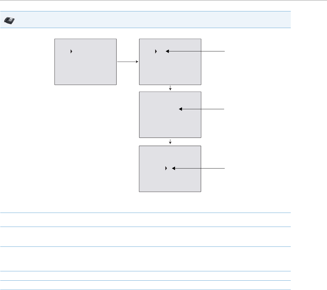
Operational Features
5-208 41-001343-02 REV04 – 05.2014
4. Press the CHANGE key for the mode you selected in step 2. This displays the Call Forward State screen.
Note:
You can press the AllAccts key to copy the settings in the current Call Forward Settings screen for a specific call forward mode, to every
account on the phone. Every account will have the same settings for that call forward mode.
5. Press the CHANGE key in the CFWD State screen. With the cursor in the “State” field, toggle the state ON and OFF by pressing the CHANGE
key.
6. Use the DOWN arrow key to scroll to the “Number” field. Enter a phone number to apply to the current state in focus. When the phone is in
the state you specified, and a call comes into the phone, it forwards the call to the number you specify.
Use the BACKSPACE key if required to delete characters.
7. Use the DOWN arrow key to scroll to the “No. Rings” field. Press the CHANGE key to select the number of rings to apply to the phone for call
forwarding incoming calls. Valid values are 1 to 20. Default is 3.
When the phone receives an incoming call, and call forward is configured on the phone, the phone rings the number of times you specify
in the No. Rings screen, and then forwards the call.
8. Press DONE in the CFWD State Screen to save all changes.
9. Press DONE in the CFWD Mode Screen to save all changes.
IP Phone UI
State: OFF
Number:
No. Rings: 1
Change
Cancel
AllAccts Done
Call Forward
Mode No Answer
State: ON
Number:5551212
No. Rings: 3
Change
Cancel
AllAccts Done
Call Forward
Mode No Answer
State: ON
Number:
No. Rings: 1
Change
Cancel
AllAccts Done
Call Forward
Mode No Answer
State: ON
Number:5551212_
No. Rings: 1
Backspace
Cancel
AllAccts Done
Call Forward
Mode No Answer
Change
Change the
State
Change the
Number
Change the
No. Rings
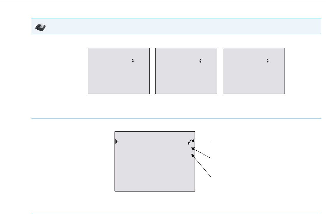
Operational Features
41-001343-02 REV04 – 05.2014 5-209
CFWD in Phone Mode
IP Phone UI
1. Use the RIGHT and LEFT arrow keys to scroll through each account.
In the above example, Screenname1, Screenname2, and Screenname3, are three accounts configured on the phone. Screenname1, 2 and 3
have “CFWD All” enabled.
Note:
In ”Phone” mode, when you change the call forward configuration for an account, the change applies to all accounts.
2. Press the Call Forward key. The Call Forward menu displays. Use the UP and DOWN arrow keys to scroll through each state type.
In the above example, CFWD All is enabled as indicated by a check mark (), CFWD Busy is enabled but no call forward phone number is
configured as indicated by a !, and CFWD No Answer is disabled, as indicated by an X.
3. Select a state using the UP and DOWN arrow keys.
You can enable/disable a specific account on the phone with any or all of the following states. However, the configuration you set will apply
to all accounts on the phone.
•All - Enables CFWD All on the phone and forwards all incoming calls to the specified number.
•Busy - Enables CFWD Busy on the phone and forwards incoming calls to a specified number if DND has been enabled OR if the phone is
currently engaged in another call.
•No Answer - Enables CFWD NoAns on the phone and forwards incoming calls to a specified number if the call has not been answered for
the specified number of rings.
Note:
If CFWD All AND CFWD Busy AND CFWD NoAns are all enabled (and/or if the account has DND enabled), the CFWD All settings take prec-
edence over CFWD Busy and CFWD NoAns.
You can also use the following keys if required:
•All Off Key- Disables all CFWD modes.
•All On Key - Disables all CFWD modes.
•CopytoAll Key - Copies the call forward phone number and state of the Call Forward mode (All, Busy, No Answer) in focus to every Call For-
ward mode. For example, if you have the cursor pointing at the “All” state and it is enabled and has a call forward phone number config-
ured, pressing the CopytoAll Key enables the Busy state and the NoAns state and assigns the same phone number to both states.
•Cancel Key - Cancels any configuration you may have made without saving. To cancel a configuration, you must press this CANCEL key
before pressing the DONE key.
01/01/14 11:00am
L1 Screenname1
CFWD All 01/01/14 11:00am
L2 Screenname2
CFWD All 01/01/14 11:00am
L3 Screenname3
Call Forward Call Forward Call Forward
CFWD All
2.Busy !
3.No Answer X
Change CopyToAll
All Off Cancel
All On Done
Call Forward Mode
1.All
Indicates
Indicates
CFWD Enabled
CFWD Disabled
Indicates
no CFWD phone
number configured
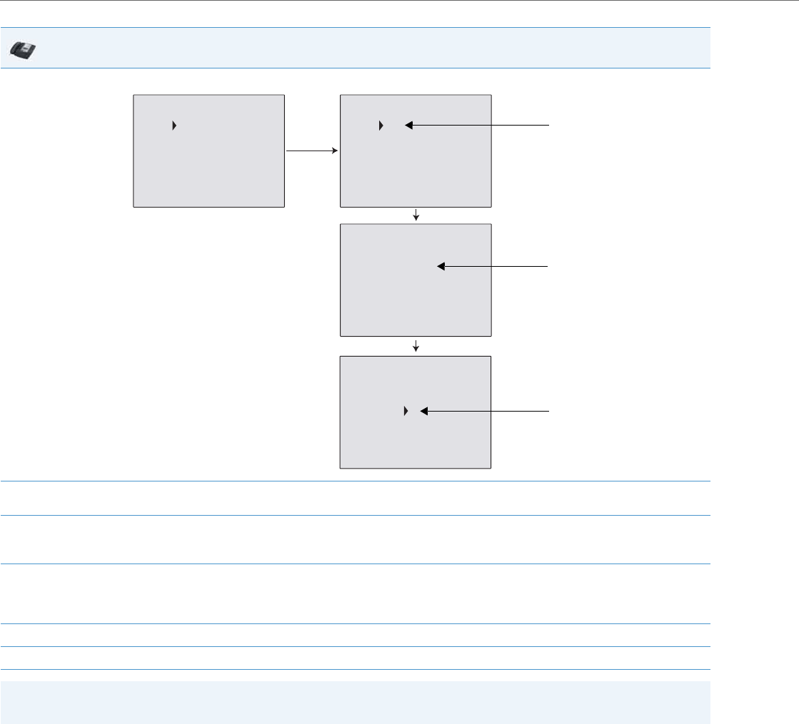
Operational Features
5-210 41-001343-02 REV04 – 05.2014
4. Press the CHANGE key for the mode you selected in step 2. This displays the Call Forward State screen.
5. Press the CHANGE key in the CFWD State screen. With the cursor in the “State” field, toggle the state ON and OFF by pressing the CHANGE
key.
6. Use the DOWN arrow key to scroll to the “Number” field. Enter a phone number to apply to the current state in focus. When the phone is in
the state you specified, and a call comes into the phone, it forwards the call to the number you specify.
Use the BACKSPACE key if required to delete characters.
7. Use the DOWN arrow key to scroll to the “No. Rings” field. Press the CHANGE key to select the number of rings to apply to the phone for call
forwarding incoming calls. Valid values are 1 to 20. Default is 3.
When the phone receives an incoming call, and call forward is configured on the phone, the phone rings the number of times you specify
in the No. Rings screen, and then forwards the call.
8. Press DONE in the CFWD State Screen to save all changes.
9. Press DONE in the CFWD Mode Screen to save all changes.
Note:
In “Phone” mode, the configuration applies to all the accounts on the phone.
IP Phone UI
State: OFF
Number:
No. Rings: 1
Change
Cancel
AllAccts Done
Call Forward
Mode No Answer
State: ON
Number:5551212
No. Rings: 3
Change
Cancel
AllAccts Done
Call Forward
Mode No Answer
State: ON
Number:
No. Rings: 1
Change
Cancel
AllAccts Done
Call Forward
Mode No Answer
State: ON
Number:5551212_
No. Rings: 1
Backspace
Cancel
AllAccts Done
Call Forward
Mode No Answer
Change
Change the
State
Change the
Number
Change the
No. Rings
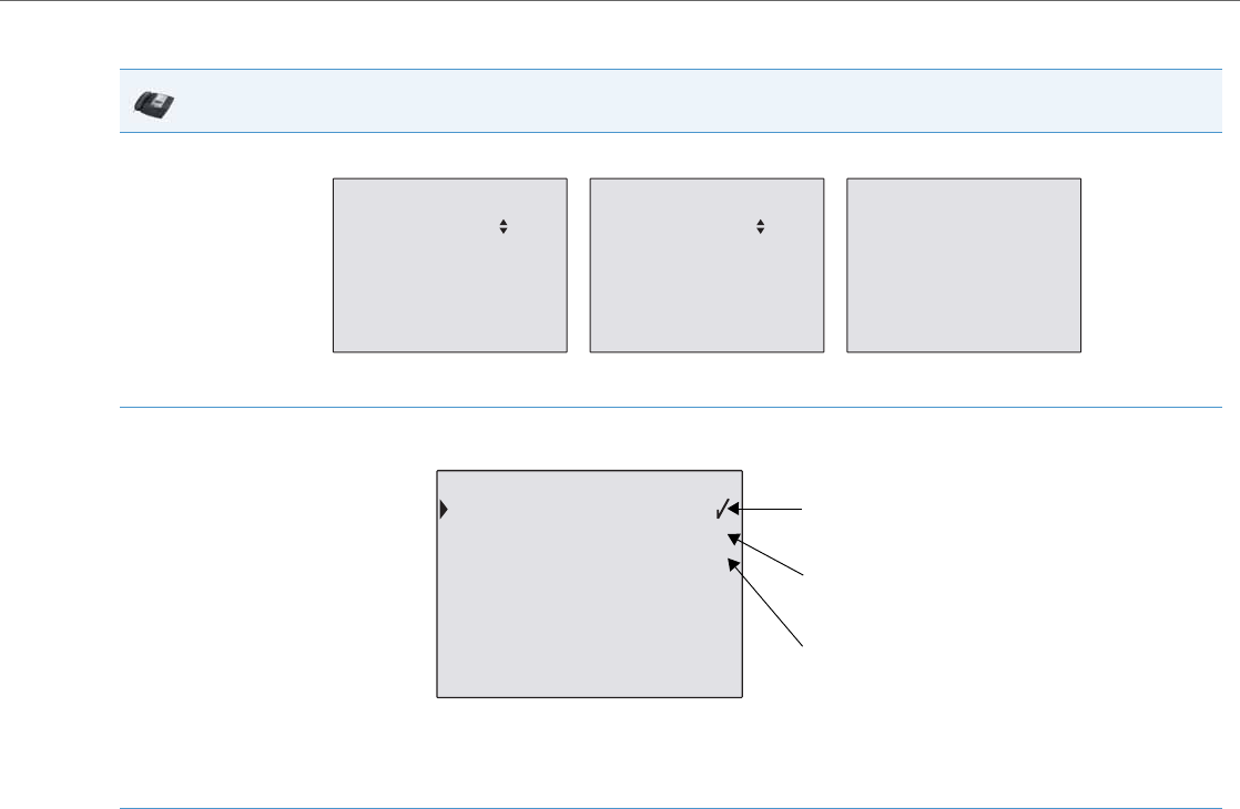
Operational Features
41-001343-02 REV04 – 05.2014 5-211
CFWD in Custom Mode
IP Phone UI
1. Use the RIGHT and LEFT arrow keys to scroll through each account.
In the above example, Screenname1, Screenname2, and Screenname3, are three accounts configured on the phone. Screenname1 has
“CFWD All” enabled, Screenname2 has “CFWD Busy” enabled, and Screenname3 has CFWD disabled as indicated by no message displayed.
2. With the account in focus on the IP Phone UI, press the Call Forward key. The Call Forward Account screen displays which lists all the
accounts on the phone. Use the UP and DOWN arrow keys to scroll through each account.
In the above example, Screenname1 has one or more CFWD states enabled as indicated by a check mark (), Screenname 2 has one or
more CFWD states enabled but a specific state has no call forward phone number configured as indicated by a !, and Screenname3 has one
or more CFWD states disabled as indicated by an X.
3. Select an account using the UP and DOWN arrow keys.
You can also use the following keys if required:
•All Off Key- Disables CFWD for all accounts on the phone.
•All On Key - Enables CFWD for all accounts on the phone.
•CopytoAll Key - Copies all settings for the account you select, to all other accounts on the Call Forward Account screen. For example, if
you have the cursor pointing at Screenname1, and you press the CopytoAll key, all of the CFWD settings for Screenname1 are copied to
Screenname2 and Screenname3.
•Cancel Key - Cancels any configuration you may have made without saving. To cancel a configuration, you must press this CANCEL key
before pressing the DONE key.
01/01/14 11:00am
L1 Screenname1
CFWD All 01/01/14 11:00am
L2 Screenname2
CFWD Busy 01/01/14 11:00am
L3 Screenname3
Call Forward Call Forward Call Forward
2.Screenname2 !
3.Screenname3 X
Change CopytoAll
All Off Cancel
All On Done
Call Forward
1.Screenname1
Indicates
Indicates
CFWD Enabled
CFWD Disabled
Indicates
no CFWD phone
number configured
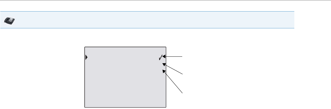
Operational Features
5-212 41-001343-02 REV04 – 05.2014
4. After selecting an account, press CHANGE.
The Call Forward Mode screen displays for the account you selected. Use the UP and DOWN arrow keys to scroll through each state type.
In the above example, CFWD All is enabled as indicated by a check mark (), CFWD Busy is enabled but no call forward phone number is
configured as indicated by a !, and CFWD No Answer is disabled, as indicated by an X.
Select a state for the selected account(s) using the UP and DOWN arrow keys.
You can enable/disable any or all of the following states for a specific account or for all accounts (with individual configurations):
•All - Enables CFWD All for an account and forwards all incoming calls for that account, to the specified number. The phone number can
be different between accounts.
•Busy - Enables CFWD Busy for an account and forwards incoming calls to a specified number if DND has been enabled for that account
OR if that account is currently engaged in another call. The phone number can be different between accounts.
•No Answer - Enables CFWD NoAns for an account and forwards incoming calls to a specified number if the call has not been answered for
a specified number of rings. The phone number can be different between accounts.
Note:
If CFWD All AND CFWD Busy AND CFWD NoAns are all enabled (and/or if the account has DND enabled), the CFWD All settings take prec-
edence over CFWD Busy and CFWD NoAns.
You can also use the following keys if required:
•All Off Key- Disables all CFWD states for the selected account.
•All On Key - Enables all CFWD states for the selected account.
•CopytoAll Key - Copies the call forward phone number and state of the selected Call Forward mode (All, Busy, No Answer) to every Call
Forward mode of that account. For example, if you have the cursor pointing at the “All” state and it is enabled and has a call forward phone
number configured, pressing the CopytoAll Key enables the Busy state and the NoAns state and assigns the same phone number to both
states.
•Cancel Key - Cancels any configuration you may have made without saving. To cancel a configuration, you must press this CANCEL key
before pressing the DONE key.
IP Phone UI
2.Busy !
3.No Answer X
Change CopyToAll
All Off Cancel
All On Done
Call Forward Mode
1.All
Indicates
Indicates
CFWD Enabled
CFWD Disabled
Indicates
no CFWD phone
number configured
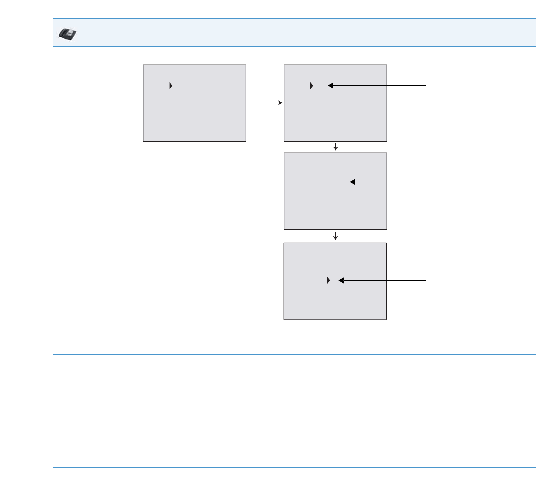
Operational Features
41-001343-02 REV04 – 05.2014 5-213
5. Press the CHANGE key for the mode you selected in step 4. This displays the Call Forward State screen.
Note:
You can press the AllAccts key to copy the settings in the current Call Forward Settings screen for a specific call forward mode, to every
account on the phone. Every account will have the same settings for that call forward mode.
6. Press the CHANGE key in the CFWD State screen. With the cursor in the “State” field, toggle the state ON and OFF by pressing the CHANGE
key.
7. Use the DOWN arrow key to scroll to the “Number” field. Enter a phone number to apply to the current state in focus. When the phone is in
the state you specified, and a call comes into the phone, it forwards the call to the number you specify.
Use the BACKSPACE key if required to delete characters.
8. Use the DOWN arrow key to scroll to the “No. Rings” field. Press the CHANGE key to select the number of rings to apply to the phone for call
forwarding incoming calls. Valid values are 1 to 20. Default is 3.
When the phone receives an incoming call, and call forward is configured on the phone, the phone rings the number of times you specify
in the No. Rings screen, and then forwards the call.
9. Press DONE in the CFWD State screen to save all changes.
10. Press DONE in the CFWD Mode screen to save all changes.
11. Press DONE in the CFWD Account screen to save all changes.
IP Phone UI
State: OFF
Number:
No. Rings: 1
Change
Cancel
AllAccts Done
Call Forward
Mode No Answer
State: ON
Number:5551212
No. Rings: 3
Change
Cancel
AllAccts Done
Call Forward
Mode No Answer
State: ON
Number:
No. Rings: 1
Change
Cancel
AllAccts Done
Call Forward
Mode No Answer
State: ON
Number:5551212_
No. Rings: 1
Backspace
Cancel
AllAccts Done
Call Forward
Mode No Answer
Change
Change the
State
Change the
Number
Change the
No. Rings

Operational Features
5-214 41-001343-02 REV04 – 05.2014
Configuring CFWD via the IP Phone UI (6739i)
If you enable/disable CFWD using the configuration files or the Aastra Web UI, you can use the CFWD screens that dis-
play to the . You can access the CFWD parameters by pressing a configured CFWD key (if previously configured) OR by
pressing Options->Call Forward on the phone’s front panel.
The following procedure assumes you have already configured a CFWD key AND assumes there are three accounts con-
figured on the phone.
Notes:
•If there is no CFWD key configured on the phone or it is removed, you can still enable CFWD via the at the path
Options->Call Forward.
•If there is only one account configured on the phone, then the mode setting is ignored and the phone behaves as if
the mode was set to “Phone”.
•Using the Aastra Web UI, if you change the CFWD key mode to “Phone”, all accounts synchronize to the current set-
ting of Account 1..
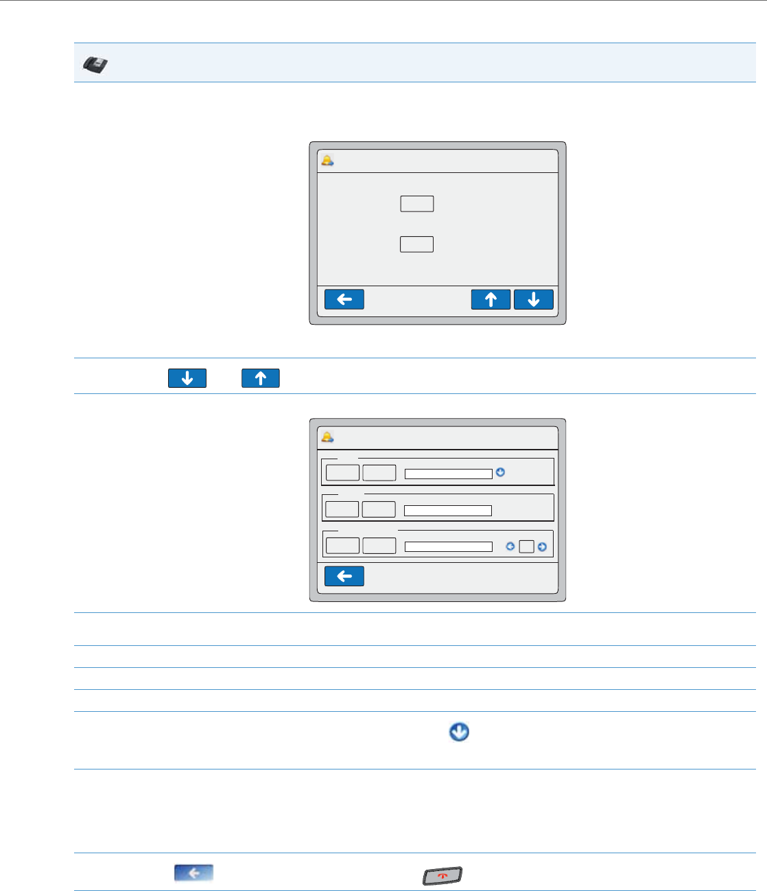
Operational Features
41-001343-02 REV04 – 05.2014 5-215
CFWD in Account Mode
IP Phone UI
1. Press the <Services> Key, then press the <Call Forward> button.
or
Press a pre-configured Call Forward softkey.
The following screen displays.
2. Use the and keys to scroll the list of accounts and select an account to apply CFWD.
3. Press <Edit>. The screen displays for the account you selected. The following example shows the CFWD screen for John’s account.
4. Select the parameter you want to enable (ALL, BUSY, and/or NO ANSWER). Selecting the ALL parameter call forwards all calls to another
number regardless of the state of your phone.
5. Press the <On> button to turn the CFWD parameter ON or the <Off> button to turn the CFWD parameter OFF.
6. Press the “Phone Number” field. A pop-up keyboard displays.
7. Using the keyboard, enter the phone number that your phone will call forward to and press <Enter>.
8. If you enter a phone number for the ALL parameter, you can press the
to automatically copy the same phone number to the BUSY and NO ANSWER phone number fields.
9. For the NO ANSWER parameter, in the “No. Rings” field, select the number of rings you want your phone to perform before call forwarding
a call.
Note:
If All AND Busy AND NoAns are all enabled, and if the account has DND enabled, the CFWD All settings take precedence over CFWD Busy
and CFWD NoAns.
10. Press the to return to the previous menu or press the to return to the idle screen.
Call Forward Account Mode
Call Forward>Account 12 : 45pm
Mon Jan 1
Edit
John
Sue Edit
CFWD ALL: OFF
CFWD BUSY: OFF
CFWD NO ANS: OFF
CFWD ALL: OFF
CFWD BUSY: OFF
CFWD NO ANS: OFF
Call Forward>John 12 : 45pm
Mon Jan 1
On
ALL
Off Copy to all modes
Phone Number
BUSY
On Off
Phone Number
On Off
Phone Number
NO ANSWER
1
No. Rings
Copy to all modes
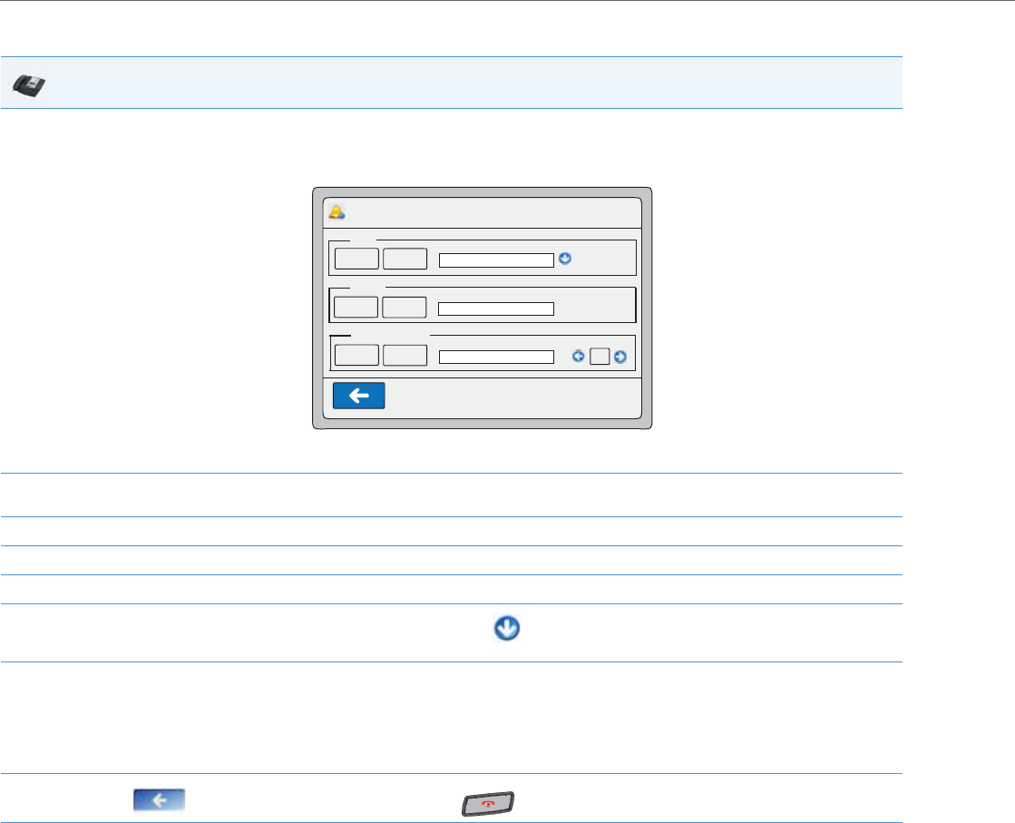
Operational Features
5-216 41-001343-02 REV04 – 05.2014
CFWD in Phone Mode
IP Phone UI
1. Press the <Services> Key, then press the <Call Forward> button.
or
Press a pre-configured Call Forward softkey.
The following screen displays.
2. Select the parameter you want to enable (ALL, BUSY, and/or NO ANSWER). Selecting the ALL parameter call forwards all calls to another
number regardless of the state of your phone.
3. Press the <On> button to turn the CFWD parameter ON or the <Off> button to turn the CFWD parameter OFF.
4. Press the “Phone Number” field. A pop-up keyboard displays.
5. Using the keyboard, enter the phone number that your phone will call forward to and press <Enter>.
6. If you enter a phone number for the ALL parameter, you can press the to automatically copy the same phone
number to the BUSY and NO ANSWER phone number fields.
7. For the NO ANSWER parameter, in the “No. Rings” field, select the number of rings you want your phone to perform before call forwarding
a call.
Note:
If All AND Busy AND NoAns are all enabled, and if the account has DND enabled, the CFWD All settings take precedence over CFWD Busy and
CFWD NoAns.
8. Press the to return to the previous menu or press the to return to the idle screen.
Call Forward Phone Mode
Call Forward>Global 12 : 45pm
Mon Jan 1
On
ALL
Off Copy to all modes
Phone Number
BUSY
On Off
Phone Number
On Off
Phone Number
NO ANSWER
1
No. Rings
Copy to all modes
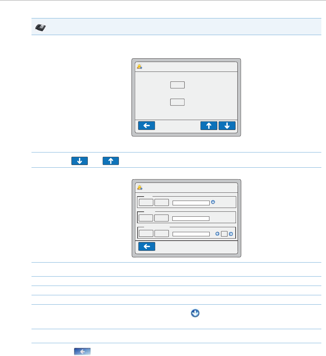
Operational Features
41-001343-02 REV04 – 05.2014 5-217
CFWD in Custom Mode
IP Phone UI
1. Press the <Services> Key, then press the <Call Forward> button.
or
Press a pre-configured Call Forward softkey.
The following screen displays.
2. Use the and keys to scroll the list of accounts and select an account to apply CFWD.
3. Press <Edit>. The screen displays for the account you selected. The following example shows the CFWD screen for John’s account.
4. Select the parameter you want to enable (ALL, BUSY, and/or NO ANSWER). Selecting the ALL parameter call forwards all calls to another
number regardless of the state of your phone.
5. Press the <On> button to turn the CFWD parameter ON or the <Off> button to turn the CFWD parameter OFF.
6. Press the “Phone Number” field. A pop-up keyboard displays.
7. Using the keyboard, enter the phone number that your phone will call forward to and press <Enter>.
8. If you enter a phone number for the ALL parameter, you can press the
to automatically copy the same phone number to the BUSY and NO ANSWER phone number fields.
9. For the NO ANSWER parameter, in the “No. Rings” field, select the number of rings you want your phone to perform before call forwarding
a call.
10. Press the to return to the previous menu.
Call Forward Custom Mode
Call Forward>Account 12 : 45pm
Mon Jan 1
Edit
John
Sue Edit
CFWD ALL: OFF
CFWD BUSY: OFF
CFWD NO ANS: OFF
CFWD ALL: OFF
CFWD BUSY: OFF
CFWD NO ANS: OFF
Call Forward>Global 12 : 45pm
Mon Jan 1
On
ALL
Off Copy to all modes
Phone Number
BUSY
On Off
Phone Number
On Off
Phone Number
NO ANSWER
1
No. Rings
Copy to all modes
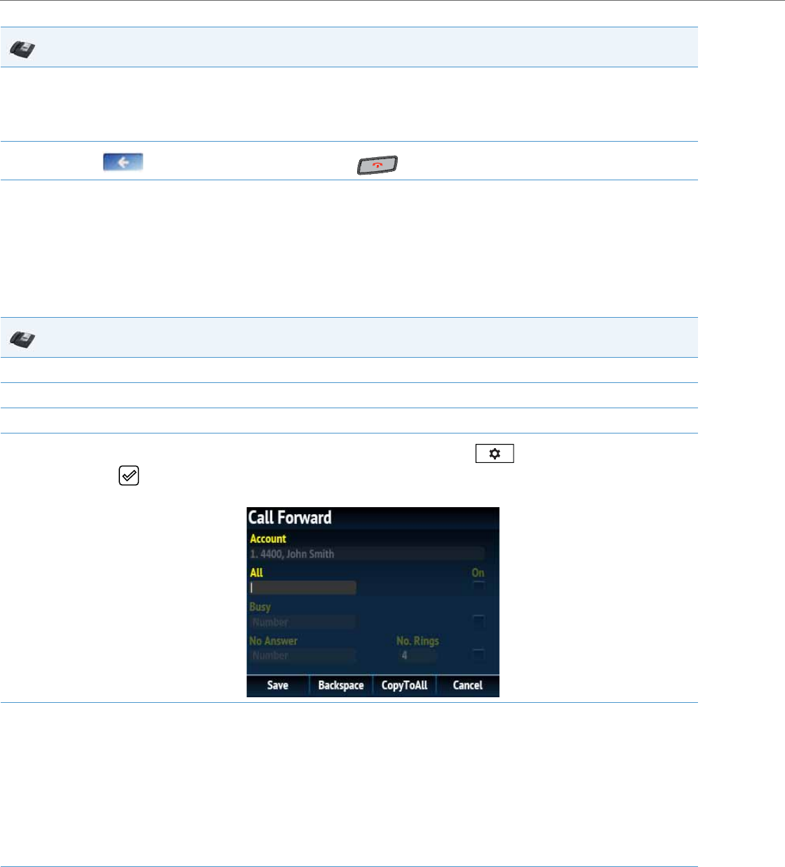
Operational Features
5-218 41-001343-02 REV04 – 05.2014
Configuring Call Forward via the IP Phone UI (6867i)
Once Call Forward is enabled on your phone, you can access the Call Forward menus by pressing a pre-configured Call
Forward key, or by selecting Options > Call Forward from the IP phone UI.
CFWD in Account Mode
11. To configure CFWD for additional accounts, repeat steps 2 through 9.
Note:
If All AND Busy AND NoAns are all enabled, and if the account has DND enabled, the CFWD All settings take precedence over CFWD Busy and
CFWD NoAns.
12. Press the to return to the previous menu or press the to return to the idle screen.
IP Phone UI
1. From the Home screen press the 4 navigation key to move to the Line Selection screen.
2. Highlight the desired account using the 2 and 5 navigation keys.
3. Press the 3 navigation key to go back to the Home screen
4. With the account in focus on Home screen, press the configured Call Fwd softkey or press , navigate to the Call Forward option
and press the button or Select softkey.
The Call Forward screen displays for the account you selected.
5. Enter forwarding numbers using the dialpad keys for any of the following states:
•All: Forwards all incoming calls for the respective account to the specified number.
•Busy: Forwards incoming calls to a specified number if DND has been enabled for that account OR if the account is currently engaged in
another call.
•No Answer: Forwards incoming calls to a specified number if the call has not been answered for the specified number of rings.
Notes:
•Pressing the 2 navigation key moves the selection to the next field/checkbox.
•If All and Busy and No Answer are all enabled (and/or if the account has DND enabled), the All settings take precedence over Busy and No
Answer.
•Pressing the CopyToAll key copies the call forward number of the Call Forward mode in focus to every Call Forward mode of that account.
For example, if you have the cursor pointing at the All state and has a call forward phone number configured, pressing the CopytoAll key
assigns the same phone number to the Busy and No Answer states as well.
6. If configuring a forwarding number for the No Answer state, navigate to the No. Rings field and press the 3 or 4 navigation keys to
change the desired number of rings.
IP Phone UI
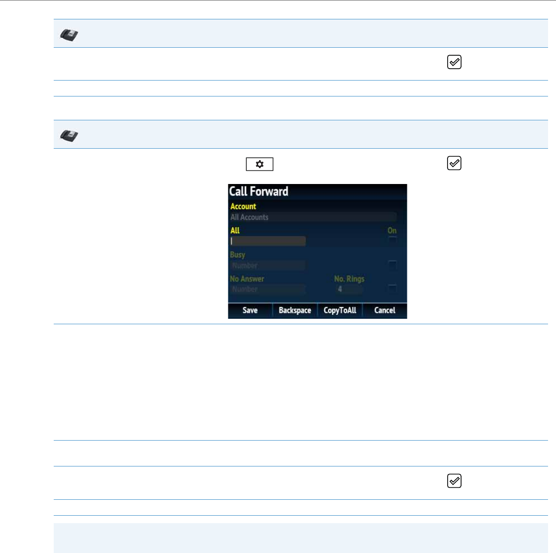
Operational Features
41-001343-02 REV04 – 05.2014 5-219
CFWD in Phone Mode
7. Using the 2 navigation key, move to the On checkbox beside the respective Call Forward mode and press the button to enable the Call
Forward mode.
8. Press the Save softkey to save your changes.
IP Phone UI
1. Press the configured Call Fwd softkey or press , navigate to the Call Forward option and press the button or Select softkey.
The Call Forward screen displays and is applicable to all accounts configured on the phone.
2. Enter forwarding numbers using the dialpad keys for any of the following states:
•All: Forwards all incoming calls for the respective account to the specified number.
•Busy: Forwards incoming calls to a specified number if DND has been enabled for that account OR if the account is currently engaged in
another call.
•No Answer: Forwards incoming calls to a specified number if the call has not been answered for the specified number of rings.
Notes:
•Pressing the 2 navigation key moves the selection to the next field/checkbox.
•If All and Busy and No Answer are all enabled (and/or if the account has DND enabled), the All settings take precedence over Busy and No
Answer.
•Pressing the CopyToAll key copies the call forward number of the Call Forward mode in focus to every Call Forward mode of that account.
For example, if you have the cursor pointing at the All state and has a call forward phone number configured, pressing the CopytoAll key
assigns the same phone number to the Busy and No Answer states as well.
3. If configuring a forwarding number for the No Answer state, navigate to the No. Rings field and press the 3 or 4 navigation keys to
change the desired number of rings.
4. Using the 2 navigation key, move to the On checkbox beside the respective Call Forward mode and press the button to enable the Call
Forward mode.
5. Press the Save softkey to save your changes.
Note:
In Phone mode, the configuration applies to all the accounts on the phone.
IP Phone UI
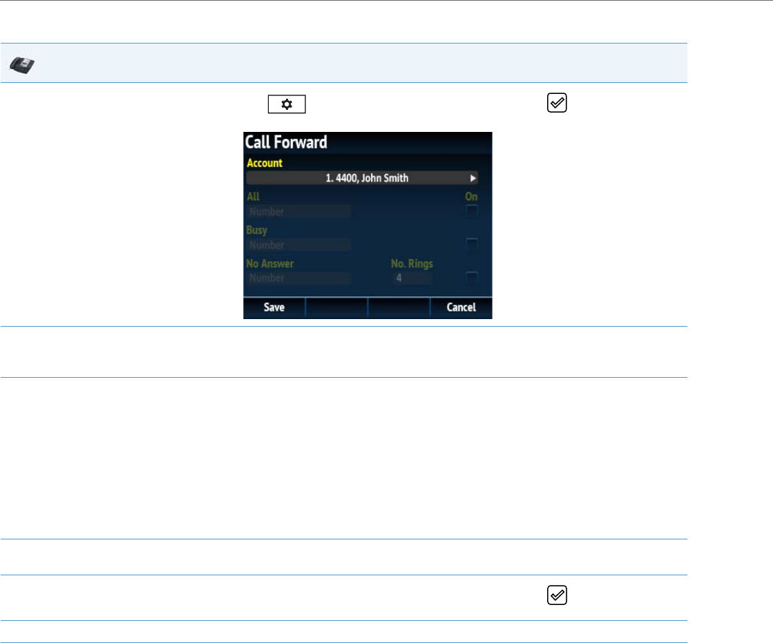
Operational Features
5-220 41-001343-02 REV04 – 05.2014
CFWD in Custom Mode
IP Phone UI
1. Press the configured Call Fwd softkey or press , navigate to the Call Forward option and press the button or Select softkey.
The Call Forward screen displays.
2. Press the 3 or 4 navigation keys to change to the desired account.
Note:
Select All Accounts if you want your changes to be made to all the accounts configured on the phone.
3. Enter forwarding numbers using the dialpad keys for any of the following states:
•All: Forwards all incoming calls for the respective account to the specified number.
•Busy: Forwards incoming calls to a specified number if DND has been enabled for that account OR if the account is currently engaged in
another call.
•No Answer: Forwards incoming calls to a specified number if the call has not been answered for the specified number of rings.
Notes:
•Pressing the 2 navigation key moves the selection to the next field/checkbox.
•If All and Busy and No Answer are all enabled (and/or if the account has DND enabled), the All settings take precedence over Busy and No
Answer.
•Pressing the CopyToAll key copies the call forward number of the Call Forward mode in focus to every Call Forward mode of that account.
For example, if you have the cursor pointing at the All state and has a call forward phone number configured, pressing the CopytoAll key
assigns the same phone number to the Busy and No Answer states as well.
4. If configuring a forwarding number for the No Answer state, navigate to the No. Rings field and press the 3 or 4 navigation keys to
change the desired number of rings.
5. Using the 2 navigation key, move to the On checkbox beside the respective Call Forward mode and press the button to enable the Call
Forward mode.
6. Press the Save softkey to save your changes.

Operational Features
41-001343-02 REV04 – 05.2014 5-221
SIP Phone Diversion Display
When an outgoing call from the phone is being diverted to another destination (i.e. via call forward), the phone displays
the Caller ID (phone number and/or caller name) of the new destination and the reason for the call diversion. Similarly, at
the new destination, the Caller ID of the original call destination now displays
Call Diversion Example
You can enable or disable this feature on a global or per-line basis using the configuration files only.
Configuring SIP Diversion Display on the Phone
Use the following procedures to configure SIP diversion display on the IP phones.
Limitations
•The diversion header assumes that the ID of the 'diverted' caller is passed in a URI style manner.
•This feature relies on the server supporting and generating the Diversion header; the phone does not generate the
header itself.
•Diversion header parameters such as counter, limit, privacy, screen, and extension are not recognized or supported by
the phone. However, they are still passed along during the diversion process.
Display Name Customization
By default, if the IP phone receives an incoming call and the number of the incoming call matches an entry in the local
directory, the IP phone will display the information stored in the local directory instead of the display name of the INVITE.
The “directory lookup suppression pattern” allows for the customization of the name displayed on the IP phone’s screen
and suppression of the local directory lookup.
1. Tim calls Mark at x400.
2. Mark’s phone is busy.
3. Mark’s phone diverts the incoming call to another destination (Roger @ x 464).
4. Tim’s phone displays name and extension of where the call is being diverted to and reason for diverting the call. The
screen scrolls between Screen 1 and Screen 2.
5. Roger’s phone accepts the call and displays the name and number of the phone the incoming call (Tim) and the name
(or number) of the original destination (Mark). The screens scroll between Screen 1 and Screen 2.
Note:
If proxy servers exist in the network, it is possible that multiple diversions can take place on the phones. When multiple
diversion headers are returned in a single 302 response back to the originating phone, the phone that originated the
call (i.e., Tim’s phone in above example) displays the URI of the newest (first encountered) Diversion header, but dis-
plays the REASON of the oldest (last encountered) Diversion Header. The phone that receives the diverted call (i.e.,
Roger’s phone in example above) displays the information of the oldest diverted call (last encountered).
Configuration Files
For specific parameters you can set in the configuration files, see Appendix A, the section, “SIP Diversion Display” on pageA-132.

Operational Features
5-222 41-001343-02 REV04 – 05.2014
This parameter is useful in such cases where a call manager will intentionally modify the display name according to a
specific scenario. For example, if a Manager forwards an incoming call to an employee, the call manager may modify the
display name to state “--> [Manager’s Name] Caller’s Name”. With the “directory lookup suppression pattern” parame-
ter configured for “-->” pattern matching, the IP phone will bypass the local directory lookup and the phone’s screen will
display the call as intended by the call manager.
Pattern Rules and Syntax
The customized display name must start with the pattern. The patterns that can be configured include the following reg-
ular expressions:
•“-->x+”
•“==>x+”
•“@@@x+”
•“aaax+”
Additionally, the pattern syntax supports the regular expression | to specify multiple OR combined patterns (e.g. “--
>x+|==>x+|aaax+”).
Configuring the Display Name Customization Feature
Use the following procedures to configure the display name customization feature.
Notes:
•Pattern matching is only applied for incoming calls and against the From header display name for incoming calls.
•Pattern matching is applied to shared lines.
•Pattern matching is not applied against the display name in the P-Asserted-Identity (PAI) header.
Configuration Files
For specific parameters you can set in the configuration files, see Appendix A, the section, “Display Name Customization Settings” on pageA-133.

Operational Features
41-001343-02 REV04 – 05.2014 5-223
Displaying Call Destination for Incoming Calls
The IP Phones allow an Administrator to enable and disable the call destination name in the “TO” header of the INVITE
message for incoming calls. When this feature is enabled, the call destination name displays on the LCD of the phone. This
allows the user to easily determine the intended destination of an incoming call.
Behavior of the Phone
When this feature is enabled, the phone behaves as follows:
The call destination information displays on multiple screens that scroll every 3 seconds.
Configuring the Display of Call Destination for Incoming Calls
Use the following procedures to configure the display of call destination for incoming calls on the IP Phones.
Limitations
The following are limitations of this feature:
•Any call destination name exceeding the screen length is truncated by the phone.
•The CT cordless handsets do not support this feature.
•Page scrolling every 3 seconds is hard-coded and not configurable.
Callers List
The IP phones have a "Callers List" feature that store the name, phone number, and incremental calls, for each call received
by the phone. You can enable and disable the Callers List feature using the configuration files. When disabled, the Callers
List does not display on the IP phone UI and the Caller List key is ignored when pressed.
When enabled, you can view, scroll, and delete line items in the Callers List from the IP phone UI. You can also directly dial
from a displayed line item in the Callers List. You can download the Callers List to your PC for viewing using the Aastra Web
UI.
IF THEN
A value exists for the Display Name field in the “TO” header of the INVITE
message for incoming calls... the phone displays the call destination name.
Display Name field is empty... the phone uses the name specified for the “Screen name 1” parameter.
“Screen name 1” parameter is empty... the phone uses the name specified for the “Display Name” parameter.
“Display Name” parameter is empty... the phone uses the name specified for the “SIP User Name” parameter.
“SIP User Name” parameter is empty... the phone uses the name specified for the “Call Destination Number”
parameter.
Note:
When both call diversion and call destination are enabled, the formation displays to the phone’s screens in the follow-
ing order:
• Screen 1: Caller info
• Screen 2: Call destination
• Screen 3: Call diversion
Configuration Files
For the specific parameter you can set in the configuration files, see Appendix A, the section, “Display of Call Destination for Incoming Calls” on pageA-
133.
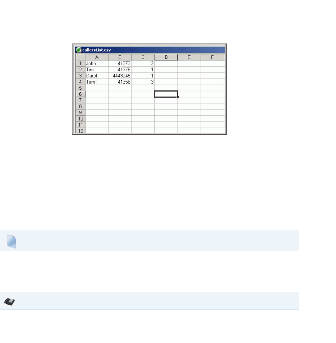
Operational Features
5-224 41-001343-02 REV04 – 05.2014
When you download the Callers List, the phone stores the callerlist.csv file to your computer in comma-separated value
(CSV) format.
You can use any spreadsheet application to open the file for viewing. The following is an example of a Callers List in a
spreadsheet application.
The file displays the name, phone number, and the line that the call came in on.
Enabling/Disabling Callers List
You can enable and disable user access to the Callers List on the IP phones using the following parameter in the configu-
ration files:
•callers list disabled
Valid values for this parameter are 0 (enabled) and 1 (disabled). If this parameter is set to 0, the Callers List can be
accessed by all users. If this parameter is
set to 1, the IP phone does not save any caller information to the Caller List. For any applicable phones, the "Callers List"
option on the IP phone is removed from the Services menu, and the Caller List key is ignored if pressed by the user.
Use the following procedures to enable/disable the Callers List on the IP phones.
Using the Callers List
Use the following procedure to access and use the Callers List.
Configuration Files
For specific parameters you can set in the configuration files for enabling/disabling the Callers List, see Appendix A, the section, “Callers List Settings”
on pageA-109.
IP Phone UI
1. On the 9143i, 6863i, 6865i, and all 6700i phones:
Press the “Callers List” key on the phone to enter the Callers List.
On the 9480i, 9480i CT:
Press the “Services” key on the phone, and then select “Callers List” from the list of options.
2. Use the 5 and 2 to scroll through the line items in the Callers List.
To the left of a line item, a b icon displays with the handset ON or OFF the receiver. The ON receiver indicates the call came in as a missed
call. The OFF receiver indicates the call came in and was answered.
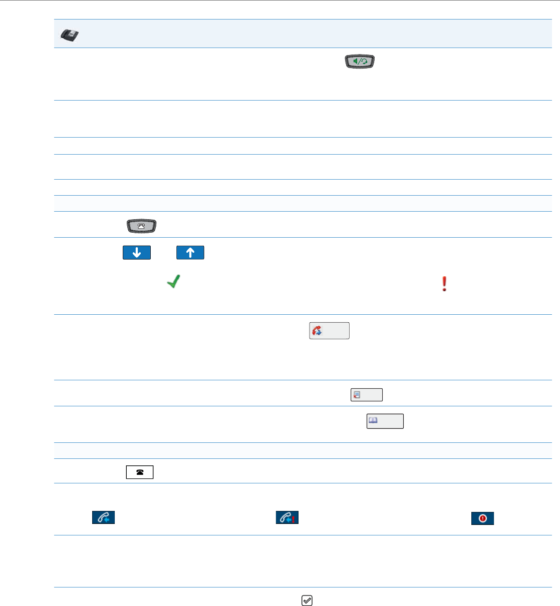
Operational Features
41-001343-02 REV04 – 05.2014 5-225
3. To dial a displayed entry from the Callers List, pick up the handset, press the key, or press a line key.
Note:
After selecting a number from the Callers List, you can edit the number if necessary.
4. To delete all entries in the Callers list, press the 3 Delete key at the "Callers List" header.
To delete a line item from the Callers List, select the line item you want to delete and press the 3 Delete key.
5. To cancel a delete function, press the 5 or 2 keys.
6. To save a line item to a programmable key for speeddialing, press the 3 Save key and enter the line number at the "Save to?" prompt that
is already configured for speeddialing at a programmable key.
7. To exit the Callers List, press the “Callers List” key again or the “Goodbye” key.
For the 6739i:
1. Press the key on the phone to enter the Callers List.
2. Use the and keys to navigate to the Caller record for which you want to call.
A GREEN checkmark displays next to the entries that were answered. A RED exclamation point displays next to the entries
that were missed calls.
3. To dial from the Callers List, press the Caller record and then press . The phone automatically dials the number from the record
you selected.
Note:
After selecting a number from the Callers List, you can edit the number if necessary.
4. To delete a record from the Callers List, press the Caller record and then press .
5. To save a Caller record to the directory, press the Caller record and then press the . button. The Directory displays.
Check that all of the information from the Callers record was entered correctly in the Directory List entry.
For the 6867i:
1. Press the key.
2. Use the 5 or 2 keys to scroll through the entries in the Callers List.
displays next to the entries that were answered. displays next to the entries that were not answered. displays next to
the entries that were missed calls.
3. Press 4 to see more detailed information about they Callers List entry.
Note:
The detailed view screen contains the picture ID of the caller (if available), the date and time of the incoming call, whether or not the call was
answered, the line on which the call was received, call duration (if the call was answered), any applicable call feature indicators, and the caller
ID details.
4. To dial the displayed number while in the Callers List, press the button, press the handsfree button, lift the handset, or press any of the
line keys.
Note:
After selecting a number from the Callers List, you can edit the number if necessary.
IP Phone UI
Dial
Delete
Add to
Directory
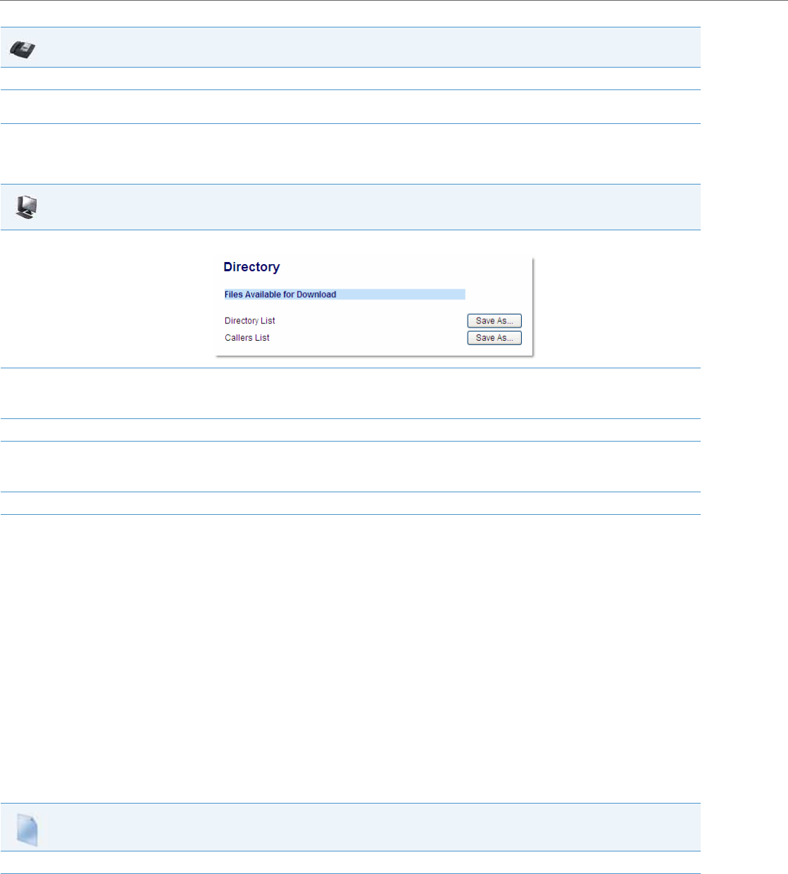
Operational Features
5-226 41-001343-02 REV04 – 05.2014
Downloading the Callers List
Use the following procedure to download the Callers List using the Aastra Web UI.
Customizable Callers List and Services Keys
The IP phones may have a Callers List key and a Services key (as a hard key or softkey/programmable key) depending on
your model phone. An Administrator can specify URI overrides for these keys using the following parameters in the con-
figuration files:
•services script
•callers list script
Specifying URIs for these parameters cause the creation of an XML custom application instead of the standard function
of the Callers List and Services keys.
An Administrator can configure these parameters using the configuration files only.
Creating Customizable Callers List and Services Keys
Use the following procedure to create customized Callers List and Services keys on the IP Phone using the configuration
files.
5. To delete a record from the Callers List, highlight the Caller record, press the Delete softkey, and then the DeleteItem softkey.
6. To save a Caller record to the directory, highlight the Caller record and then press the Copy softkey. Check that all of the information from
the Callers record was entered correctly in the Directory List entry.
Aastra Web UI
1. Click on Operation->Directory.
2. In the Callers List field, click on Save As.
A “File Download” message displays.
3. Click Save.
4. Enter the location on your computer where you want to download the Callers List and click Save.
The callerslist.csv file downloads to your computer.
5. Use a spreadsheet application to open and view the Callers List.
Configuration Files
For specific parameters you can set in the configuration files, see Appendix A, the section, “Customizable Callers List and Services Key” on pageA-110.
IP Phone UI
Operational Features
41-001343-02 REV04 – 05.2014 5-227
Missed Calls Indicator
The IP phone has a "missed calls" indicator that increments the number of missed calls to the phone. This feature is acces-
sible from the IP phone UI only.
You can enable and disable the Missed Calls Indicator feature using the configuration files. When disabled, the Missed
Calls Indicator does not increment as calls come into the IP phone.
When enabled, the number of calls that have not been answered increment on the phone’s idle screen as "<number>
New Calls". As the number of unanswered calls increment, the phone numbers associated with the calls are stored in the
Callers List. The user can access the Callers List and clear the call from the list. Once the user accesses the Callers List, the
"<number> New Calls" on the idle screen is cleared.
Enabling/Disabling Missed Calls Indicator
You can enable (turn on) and disable (turn off) the Missed Calls Indicator on the IP phones using the following parameter
in the configuration files:
•missed calls indicator disabled
Valid values for this parameter are 0 (enabled) and 1 (disabled). If this parameter is set to 0, the indicator increments as
unanswered calls come into the IP phone. If set to 1, the indicator does not increment the unanswered calls.
Use the following procedures to enable/disable the Missed Calls Indicator on the IP phones.
Accessing and Clearing Missed Calls
Use the following procedure to access and clear missed calls from the Callers List. Once you display the Callers List, the
"<number> New Calls" indicator clears.
Note:
The phones also include a “Missed-Calls-Message” field in a “message summary” event of a SIP NOTIFY message.
Configuration Files
For specific parameters you can set in the configuration files for enabling/disabling the Missed Calls Indicator, see Appendix A, the section, “Missed
Calls Indicator Settings” on pageA-114.
IP Phone UI
1. Press the “Callers List” key on the phone to enter the Callers List.
2. Use the 5 and 2 to scroll through the line items in the Callers List to find the line items that have the b icon with the receiver ON. These
are the missed calls to the phone.
3. To clear the line item from the Callers List, select the line item you want to clear and press the 3, Clear, or Delete key (depending on your
phone model).
Note:
To cancel a delete function, press the 5 or 2 keys.
The line item deletes from the Callers List.
For the 6739i:
1. Press the key on the phone to enter the Callers List.
2. Use the and keys to navigate to the Caller record marked with a indicating missed calls.
3. To delete the missed call from the Callers List, press the Caller record and then press .
Delete
Operational Features
5-228 41-001343-02 REV04 – 05.2014
Directory List
The IP phones have a "Directory List" feature that allows you to store frequently used names and numbers on the
phone. You can also dial directly from the directory entry.
Directory List Capabilities
In the Directory List a user or administrator can store a maximum of 7 numbers associated with a unique name. You can
apply pre-defined labels to the entry which include, Office, Home, Cell, and Pager, or create your own labels (for phones
with softkeys). Labels can be up to 14 characters in length for all phones with softkeys except the 6867i. The 6867i’s char-
acter length limit is variable and as such automatically truncates labels that are too long.
Reference
For more detailed information about the Directory Key on your IP phone, and the Directory List, see your Aastra
<Model-Specific> IP Phone User Guide.
Administrator/User Functions for Directory List
You can perform the following pertaining to the Directory List:
•You can enable and disable access to the Directory List using the configuration files. When disabled, the Directory List
does not display on the IP phone UI and the Directory List softkey is ignored when pressed. This is an administrator
function only.
•If the Directory List is enabled, you can view, add, change, and delete entries to/from the Directory List using the IP
phone UI. You can also directly dial a number from the Directory List. This is an administrator and user function.
•A public and private softkey can be used when at a line item in the Directory List. The Private key toggles a number in
the Directory List to private. The Public key allows a number in the Directory List to be sent to the handsets. A 6757i
CT accepts a maximum of 50 entries with the public attribute. This is an administrator and user function.
•You can download the Directory List to your PC via the Aastra Web UI. The phone stores the directorylist.csv file to your
PC in comma-separated value (CSV) format. This is an administrator and user function.
•You can use any spreadsheet application to open the file for viewing. The following is an example of a Directory List in
For the 6867i:
1. Press the key.
2. Use the 5 or 2 keys to scroll through the entries in the Callers List.
displays next to the entries that were answered. displays next to the entries that were not answered. displays next to
the entries that were missed calls.
The missed calls icon automatically clears when you highlight a different Caller record.
IP Phone UI
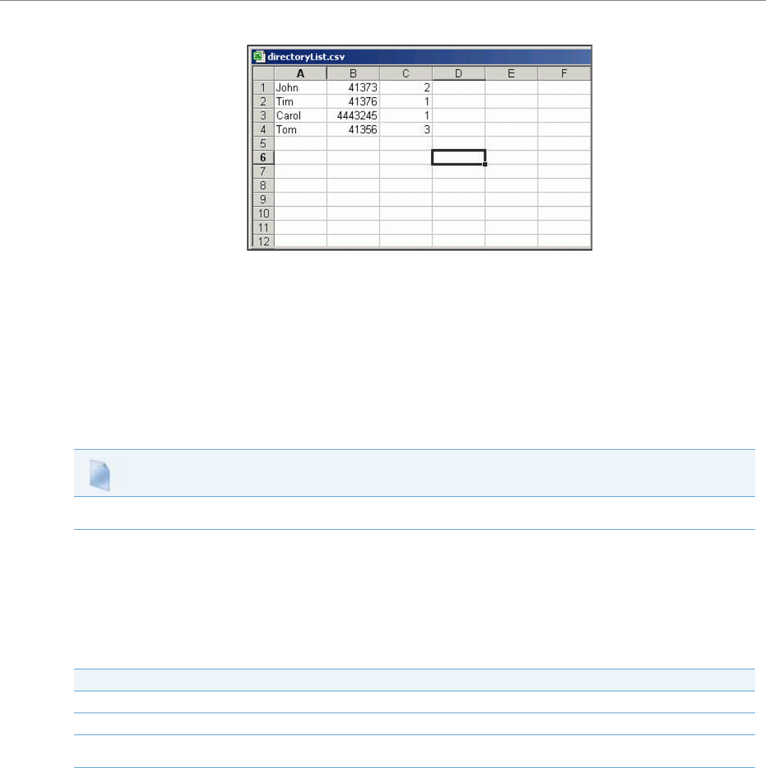
Operational Features
41-001343-02 REV04 – 05.2014 5-229
a spreadsheet application. This is an administrator and user function.
The file displays the name, phone number(s), and line number(s) for each Directory entry.
Enabling/Disabling Directory List
You can enable and disable user access to the Directory List on the IP phones using the following parameters in the config-
uration files:
•directory disabled
Valid values for this parameter are 0 (enabled) and 1 (disabled). If this parameter is set to 0, the Directory List can be
accessed by all users. If this parameter is set to 1, the Directory List does not display on the IP phone and the Directory key
is disabled. On 3-Line LCD phones, the "Directory" option is also removed from the "Services" menu.
Use the following procedures to enable/disable the Directory List on the IP phones.
Server to IP Phone Download
You can populate your IP phone Directory List with server directory files. To activate this feature, you need to add the fol-
lowing parameters to the configuration files:
•directory 1: company_directory
•directory 2: my_personal_directory
The IP phone recognizes the following characters in a Directory List:
A valid directory entry has a name, a URI number, and optional line number, and an optional mode attribute, all separated
by commas. If a line number is not present, the entry is assigned to line 1. If a mode attribute (public or private) is not
present, the entry is assigned to "Private".
Configuration Files
For specific parameters you can set in the configuration files for enabling/disabling the Directory List, see Appendix A, the section, “Directory Settings”
on pageA-107.
Character Description
’#’ Pound character; any characters appearing after the # on a line are treated as a comment
’,’ Comma character; used to separate the name, URI number, line, and mode fields within each directory entry.
’"’ Quotation mark; when pound and comma characters are found between quotes in a name field or URI number
field, they are treated as regular characters.

Operational Features
5-230 41-001343-02 REV04 – 05.2014
The following directory entries are considered valid:
# our company's directory
# updated 1 jan 2012
# mode = private, by default
#
joe foo bar, 123456789, 6
# line = 1, by default
# mode = private, by default
#
snidley whiplash, 000111222
# the parser ignores the COMMA # in the name
# mode = private, by default
#
"manny, jr", 093666888, 9
# the parser ignores the POUND # chars in the URI number
# mode = private, by default
#
hello dolly, "12#34#7", 2
Server to IP Phone Download Behavior
The software that reads directory files from the server, loads the file’s contents into the phone's NVRAM when the phone
is booting. Directory entries in the NVRAM that originate from a server directory file are “owned” by the server.
During the boot process both directory files are read, combined into a single list, and any duplicate entries are deleted
from the list. Any entries in this list that are not already in the phone's NVRAM are added to the NVRAM and flagged as
being owned by the server. Likewise, any entries in the NVRAM that are owned by the server, but are no longer in one of
the server's directory files, are removed from the NVRAM. Entries made from the IP phone UI are never touched.
Directory List Limitations
The following table indicates the maximum characters for each line and field in the Directory List.
Note:
Duplicate entries are recognized by the IP phone as those that contain the same name, URI number, and line number.
The label and mode attribute (i.e. public or private) are not taken into consideration by the IP phone when comparing
entries.
Directory List Limitations
Maximum length of a line 255 characters
Maximum length of a name 15 characters for all phones except the
6867i. The 6867i has variable character
lengths and automatically truncates
names that are too long).
Maximum length of a URI 45 characters
Maximum number directory entries in the NVRAM 200 entries
Maximum number directory entries in the NVRAM with the "public" attribute
(6757i CT only)
50 entries

Operational Features
41-001343-02 REV04 – 05.2014 5-231
Using the Directory List
Use the following procedures to access and use the Directory List.
Note:
In the following procedure, the location of keys (hard keys, softkeys, and programmable keys) on the phone are
dependant on your specific phone model. See Chapter 1, “Overview”, for the keys that are specific to your phone
model.
IP Phone UI
1. On the 9143i, 6863i, 6865i, and all 6700i phones:
Press the DIRECTORY key to enter the Directory List.
On the 9480i, 9480i CT:
Press the Services key, and then select “Directory” from the list of options.
Note:
After entering the Directory List, if no key is pressed within 3 seconds, the phone prompts you to press the first letter in the name of the
required directory entry. The phone finds and displays the first name with this letter.
2. Use the 5 and 2 to scroll through the line items in the Directory List.
To dial from an entry in the Directory List:
3. At a line item in the Directory List, pick up the handset, press the key, or press a line key.
The phone automatically dials the Directory List number for you.
To add a new entry to the Directory List:
4. a. Press the SAVE key or ADD NEW softkey (depending on your model phone) at the Directory List header screen and perform step 4.
or
Press the SAVE key or ADD NEW softkey at a line item and press the DIRECTORY key again.
b. Enter a phone number, name, and line number and press the SAVE key after each field entry.
To edit an entry in the Directory List:
5. a. At a line item in the Directory List, press the 3 key.
Note:
Use the SAVE key to scroll between the number, name and line entries.
b. Edit the phone number if required and press SAVE.
c. Edit the name if required and press SAVE.
d. Edit the line if required and press SAVE.
e. Press SAVE to save the changes and exit the editing function.
To delete an entry from the Directory List:
6. a. At a line item in the Directory List, press DELETE. The following prompt displays:
“DELETE again to erase this item”.
b. Press DELETE again to delete the entry from the Directory List.
Note:
To cancel a delete function, press the 5 or 2 keys.
Operational Features
5-232 41-001343-02 REV04 – 05.2014
Using the Directory on the 6739i
Accessing and Searching the Directory
Use the following procedures to access and search for entries in your Directory List.
To delete all entries from the Directory List:
7. a. At the Directory List header, press DELETE or DELETE LIST (depending on your phone model). The following prompt displays:
“DELETE again to erase all items”.
b. Press DELETE again to delete all entries from the Directory List.
Note:
To cancel a delete function, press the 5 or 2 keys.
To copy an entry from the Directory List to a Speeddial key (for 3-Line LCD phones):
8. At a line item in the Directory List, press the SAVE key.
The "Save to?" prompt displays.
Enter a number from 1 to 9 (associated with the keypad) where you want to save the item as a speeddial.
Note:
You must have a Speeddial key previously configured on your phone to use this feature. To configure a Speeddial key, see your <Model-Spe-
cific> User’s Guide.
9. To exit the Directory List, press the DIRECTORY key again, the GOODBYE key, or the QUIT key (depending on your specific phone model).
From the CT handsets:
10. a. Press the Public/Private softkeys to toggle between making the new entry public or private.
Note:
The entry is set to Private by default. If the entry is made Public, the entry is sent to the handsets. A 6757i CT accepts a maximum of 50
entries with the public attribute.
b. To edit an entry, use the Change softkey.
A screen displays allowing you to edit the name, phone number, and line number, as well as the public/private setting.
c. To dial a displayed entry from the Directory List, pick up the handset, press the key, or press the Dial softkey.
IP Phone UI
1. Press the Key. The Directory screen displays. The screen is blank if the Directory is empty.
2. Use the and keys to navigate the list to look for an entry.
3. Press the entry to display a single entry’s details.
IP Phone UI
Operational Features
41-001343-02 REV04 – 05.2014 5-233
Using the Search Feature in the Directory
Dialing from the Directory
You can dial a phone number or extension directly from an entry in the Directory List.
Adding an Entry
You can add up to 200 entries to your Directory. You can also store up to a maximum of 7 numbers associated with a single
entry (i.e., office number, cell number, home number, etc.). You can apply custom labels to each entry as required.
IP Phone UI
1. Press the button on the main Directory screen. A keyboard displays.
2. Enter the name or phone number of the entry for which you are searching. As you type characters on the keyboard, the entries beginning
with those characters display on the screen. When you have completed your typing, the entry you are looking for, displays on the screen
and the characters you typed display in a text box.
IP Phone UI
1. Press the Key. The Directory screen displays.
2. Use the and keys to navigate the list to look for an entry.
or
Press the button.
3. Select the entry you want to dial. All of the numbers display that are associated with the single entry (i.e., Cell, Office, Home, etc.)
Note:
A “picture ID” displays when you select an entry in the Directory if your System Administrator enabled this feature on your phone. Contact
your System Administrator for more information about the “picture ID” feature.
4. Press a number button to dial the number or extension. The phone goes off-hook and automatically dials the number from the Directory.
For example, pressing the “Office” button in the screen above dials “2345” automatically from the Directory. The outgoing call defaults to
using Line 1.
IP Phone UI
1. Press the Key. The Directory screen displays.
2. Press the button.
3. Press the “First” field, enter the first name of the person you are adding to your directory, and then press <Enter>. Use the pop-up keyboard
to enter the first name.
4. Press the “Last” field, enter the last name of the person you are adding to your directory, and then press <Enter>.
5. Press . The “Number/Label” fields display on the screen.
6. Press the “Number” field, enter the number of the person you are adding to your directory, and then press <Enter>. Use the pop-up key-
board to enter the number.
7. Press the “Label” field, enter the label associated with the number you just entered, and then press <Enter>. Use the pop-up keyboard to
enter the label.
8. Press the buttons to select a Line (1 through 9) to associate with the phone number and label you are entering. When you dial
the current number from the directory, the outgoing call uses the line number you assigned it.
9. To add another phone number and label, press An additional “Number/Label” field displays.
10. Repeat steps 6 through 8 to enter another number and label for the current entry.
Add
Add
Add
Operational Features
5-234 41-001343-02 REV04 – 05.2014
Editing an Entry
You can edit a Directory entry, number, and/or label as required from a single entry screen.
Deleting an Entry
You can delete entries from the Directory List in the following ways:
•Delete a single entry and all associated numbers and labels
•Delete all entries in the Directory List
•Delete specific numbers and labels from an entry
11. When you are finished entering Numbers/Labels for the current entry, press . This saves the entry and all associated num-
bers/labels to the Directory on your phone
Note:
When adding an entry, number, and label to the Directory, you can press the any time to cancel the entry. It is not saved to the
Directory.
12. Press the to return to the previous menu or press the to return to the idle screen.
IP Phone UI
1. Press the Key. The Directory screen displays.
2. Use the and keys to navigate the list to look for an entry.
or
Press the button.
3. Press the entry you want to edit. The single entry screen displays.
4. Press the number and/or label that you want to edit, and press the button.
5. Edit the Number and/or Label as required using the touch keypad that displays, and press .
6. Press the to return to the previous menu or press the to return to the idle screen
IP Phone UI
Deleting a single entry or all entries
1. Press the Key. The Directory screen displays.
2. Use the and keys to navigate the list to look for an entry.
or
Press the button.
3. Press the entry you want to delete. The single entry screen displays.
4. Press the button. The following screen displays.
IP Phone UI
Edit
Delete
Operational Features
41-001343-02 REV04 – 05.2014 5-235
Downloading from the Server to the IP Phone
You can use the configuration files to download the Directory List from the configuration server to the IP phone..
Use the following procedure to configure the download.
Downloading from the IP Phone to the Server
You can use the Aastra Web UI to download the Directory List from the IP phone to the configuration server.
5.
Press to delete the entry and all associated numbers and labels from the Directory. The main Directory screen displays.
or
Press to delete all entries from the Directory. The main Directory screen displays.
6. Press the to return to the previous menu or press the to return to the idle screen
Deleting a number and/or label from an entry
1. Press the Key. The Directory screen displays.
2. Use the and keys to navigate the list to look for an entry.
or
Press the button. For a procedure on using the search button, see “Using the Search Feature in the Directory” on page5-231.
3. Press the entry for which you want to delete a number/label. The single entry screen displays.
4. Press the button. All of the Numbers/Labels associated with this entry display on the screen.
5. Press the button next to the Number/Label to delete both the number and label from the entry.
or
Press the field (Number or Label) you want to delete. When the keyboard displays, press the <Backspace> key to delete the text in the field
and press <Enter>.
6. Press the button to save your change(s).
7. Press the to return to the previous menu or press the to return to the idle.
Configuration Files
For specific parameters you can set in the configuration files for downloading the Directory List, see Appendix A, the section, “Directory Settings” on
pageA-107.
IP Phone UI
Deleting a single entry or all entries
Delete
Delete All
Edit
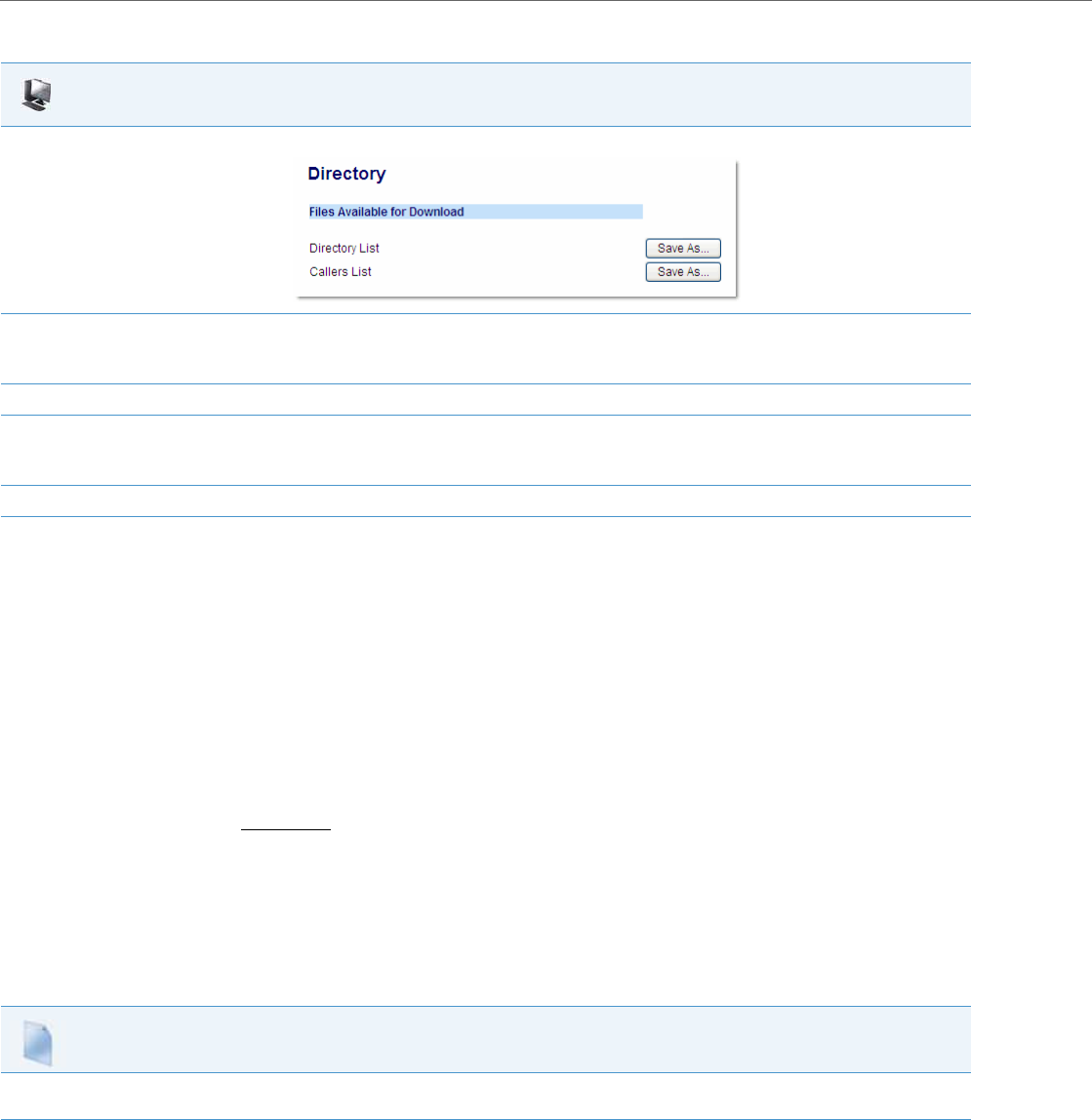
Operational Features
5-236 41-001343-02 REV04 – 05.2014
Use the following procedure to configure the download.
Local Directory Loose Number Matching
If the incoming calling number does not match exactly to the local directory, the lookup will fail and the phone will not
display the stored directory name. Now, the phone can be configured to match only the specified number of digits
against the local directory.
Administrators can enter a parameter “directory digits match” to determine the number of digits (from the incoming
call) that the phone will use to perform a lookup in the local directory to match the number to a contact. The phone will
take the last n digits of the incoming call to perform the lookup.
For example, if a local directory contains the following contact:
555123456 Spain Office
and the “directory digits match” parameter is configured (directory digits match: 9), the phone will take the last 9 digits
of the incoming number (+34555123456) and match it to the contact in the directory and display the following on the
phone:
Spain Office
+34555123456
Configuring Local Directory Loose Number Matching
Use the following procedures to configure local directory loose number matching on the IP phones.
Aastra Web UI
1. Click on Operation->Directory.
2. In the Directory List field, click on Save As.
A “File Download” message displays.
3. Click Save.
4. Enter the location on your computer where you want to download the Directory List and click Save.
The directorylist.csv file downloads to your computer.
5. Use a spreadsheet application to open and view the Directory List.
Configuration Files
For specific parameters you can set in the configuration files for configuring the local directory loose number matching, see Appendix A, the section,
“Directory Settings” on pageA-107.

Operational Features
41-001343-02 REV04 – 05.2014 5-237
Customizable Directory List Key
The IP phones may have a Directory List key (either a hard key or softkey/programmable key) depending on the model of
the phone. An Administrator can specify a URI override for the Directory List key by defining the “directory script” param-
eter in the configuration files. Specifying a URI for this parameter causes the creation of an XML custom application
instead of the standard function of the Directory List key. An Administrator can configure this parameter using the config-
uration files only.
Creating a Customizable Directory List Key
Use the following procedure to create a customized Directory List key on the IP Phone using the configuration files.
Voicemail
The Voicemail feature on the IP phones allow you to configure lines with phone numbers so the phone can dial out to con-
nect to a voicemail server. You associate the Voicemail numbers with the phone numbers configured on each line.
For each assigned Voicemail number, there can be a minimum of 0 or a maximum of 1 Voicemail access phone number.
The Voicemail list displays a list of phone numbers assigned to the IP phone that has registered voicemail accounts associ-
ated with them.
The phone displays up to 99 voicemails for an account even if the number of voicemails exceeds the limit.
Registered account numbers/URIs that exceed the length of the screen, either with or without the voicemail icon and the
message count, are truncated with an ellipse character at the end of the number/URI string.
The end of the Voicemail list displays the number of new voicemail messages (if any exist).
Configuring Voicemail
You configure Voicemail in the configuration files to dial a specific number to access an existing voicemail account. The
user then follows the voicemail instructions for listening to voicemails.
To configure the Voicemail feature on the IP phone, you must enter the following parameter in the configuration files:
•sip lineN vmail
You can enter a Voicemail number for each line on the phone.
Configuration Files
For specific parameters you can set in the configuration files, see Appendix A, the section, “Customizable Directory List Key” on pageA-109.
Note:
The Voicemail list does not display the voicemail access number.
Note:
Multiple voicemail registration and monitoring of multiple voicemail accounts is available on the IP phones. See
“Speeddial/MWI Key” on page5-143 for more information.
Note:
The phone must have a registered voicemail account from a server for this feature to be enabled. When no registered
voicemail accounts are registered to the phone, the display shows "List Empty".
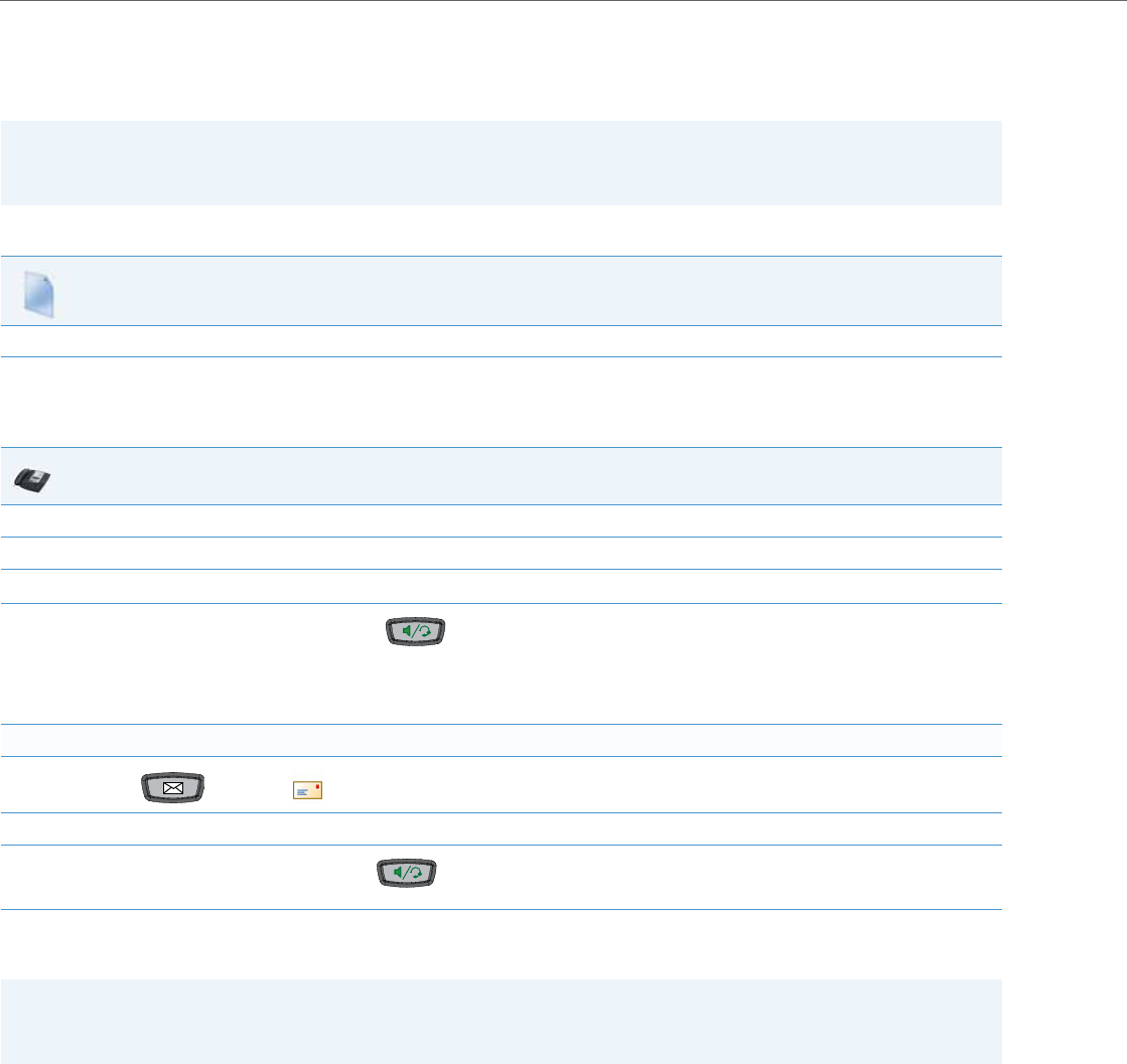
Operational Features
5-238 41-001343-02 REV04 – 05.2014
For example:
sip line1 vmail: *97
sip line2 vmail: *95
Use the following procedure to configure voicemail using the configuration files.
Using Voicemail
Use the following procedure to access and use voicemail.
From a selected item in the Voicemail list, you can also lift the handset (go offhook) to make an outgoing call using the
voicemail access phone number.
Note:
In the above example, the user would dial *97 to access the voicemail account for line 1, and *95 to access the voicemail
account for line 2.
Configuration Files
For specific parameters you can set in the configuration files, see Appendix A, the section, “Voicemail Settings” on pageA-105.
IP Phone UI
1. Press Services on the phone to display the Services menu.
2. From the Services menu, select "Voicemail".
3. Use the 5 and 2 to scroll through the line items in the Voicemail List.
4. When you have selected a line item, press the key, 4 key, or press a line softkey to make an outgoing call using the voicemail
access phone number associated with the line for which the voicemail account is registered.
From a selected item in the Voicemail list, you can also lift the handset (go offhook) to make an outgoing call using the voicemail access
phone number.
For the 6739i:
1. Press the Key or the icon on the phone.
2. Using your finger, scroll through the line items in the Voicemail list.
3. When you have selected a line item, press the Key, or press a line/call appearance key to make an outgoing call using the voicemail
access phone number associated with the line for which the voicemail account is registered.
Note:
You can also access your Voicemail via the “Services” Key on your phone if this has been setup by your System Admin-
istrator.

Operational Features
41-001343-02 REV04 – 05.2014 5-239
Visual Indicators for Voicemail on SCA-Configured Lines
Visual indicators for voicemail messages on Shared Call Appearance (SCA) lines have been implemented on the 9480i,
9480i CT, 6735i, 6737i, 6755i, 6757i, and 6757i CT model IP phones. The parameter “voice mail indicator” is available
allowing administrators the ability to configure what types of visual indicators the IP phones should display when voice-
mail messages are pending on a respective SCA line.
Administrators have three options when configuring the “voice mail indicator” parameter:
•0: When a line has pending messages, the IP phone does not display any visual indicators.
•1: When a line has pending messages, the line’s corresponding softkey will display an envelope icon and the
number of pending messages beside the softkey’s label . Additionally, the softkey’s LED will be illuminated (if available).
•2: When a line has pending messages, the line’s corresponding softkey will display only the envelope icon beside
the softkey’s label (i.e. no indication of the number of pending messages). Additionally, the softkey’s LED will be illumi-
nated (if available).
The parameter is set to 0 (no visual indicators) by default.
Configuring SCA Voicemail Visual Indicators
Use the following procedure to configure the SCA voicemail visual indicators.
Notes:
•The above behaviors are also applicable to expansion module softkeys representing SCA lines.
•For programmable keys representing SCA lines, the respective programmable key’s LED will flash when voicemail mes-
sages are pending.
•The “voice mail indicator” parameter takes precedence over the “line icon disabled” parameter. If both “voice mail
indicator” and “line icon disabled” are enabled, an envelope icon (and number of messages, if configured) will be dis-
played when voicemail messages are pending.
•For information on SCA see “Shared Call Appearance (SCA) Call Bridging”on page 5-174.
Configuration Files
For specific parameters you can set in the configuration files, see Appendix A, the section, “SCA Voicemail Indicator Settings” on pageA-106.

Operational Features
5-240 41-001343-02 REV04 – 05.2014
PIN and Authorization Code Suppression
Certain features on MX-ONE require a PIN/authorization code to be entered on the phone (for example: to register, for
authorization, locking/unlocking, or accounting).
The number format is the following:
*<feature code>*PIN# or *<feature code>*PIN*<number>#
To deactivate features, the first star is replaced by #, for example:
#<feature code>*PIN#.
Administrators can now configure the “pin suppression dial plan” parameter so that if such a feature code with a PIN is
entered, the PIN does not show up in any of the phone logs (i.e. the redial list) nor is it displayed on the screen during a
call. The phone will dynamically mask the PIN on the display within a second of the code being entered by the user.
The “pin suppression dial plan” parameter introduces new alphanumeric characters that control the masking of the
PIN: “(“ and “)”.
The following is an example value of the new configuration parameter:
"*11*(1XXX)*5555+#|*72*(1XXX)#|#73*(1XXX)#"
where (1XXX) will mask any PINs that are 4 digits long and start with 1.
This parameter value should lead to the following masking:
•Entered digits *11*1234*5555# will lead to INVITE to this number but *11******5555# is shown on the display and in
the redial list.
•Entered digits *72*1234# will lead to INVITE to this number but
*72*****# is shown on the display and in the redial list.
•Entered digits #73*1234# will lead to INVITE to this number but
#73*****# is shown on the display and in the redial list.
Use the following procedure to configure the pin suppression feature using the configuration files.
Note:
The pin will be masked with wildcard characters (i.e. “*”) on the display and in the logs.
Configuration Files
For specific parameters you can set in the configuration files, see Appendix A, the section, “PIN Suppression” on pageA-112.

Operational Features
41-001343-02 REV04 – 05.2014 5-241
XML Customized Services
Extensible Markup Language (XML) is a markup language much like HTML. HTML was designed to display data and to
focus on how data looks. XML was designed to describe data and to focus on what data is.
The following are characteristics of XML:
•XML tags are not predefined. You must define your own tags.
•XML uses a Document Type Definition (DTD) or an XML Schema to describe the data.
•XML with a DTD or XML Schema is designed to be self-descriptive
•XML is a W3C Standard Recommendation
Creating Customized XML Services on the IP Phones
The XML application for the IP phones allows users to create custom services they can use via the phone’s keyboard and
display. These services include things like weather and traffic reports, contact information, company info, stock quotes, or
custom call scripts.
The IP phone XML application supports the following proprietary objects that allow for the customization of the IP
phone’s display.
Reference
For more information about creating customized XML applications, contact Aastra Customer Support regarding the Aas-
tra XML Developer’s Guide.
XML Object Description
AastraIPPhoneTextMenu
(for Menu screens) Creates a numerical list of menu items on the IP phones.
AastraIPPhoneTextScreen
(for Text screens)
AastraIPPhoneFormattedTextScreen
(for Text screens)
Creates a screen of text that wraps appropriately.
Creates a formatted screen of text (specifies text alignment, text size, text
static or scrolling)
AastraIPPhoneInputScreen
(for User Input screens)
AastraIPPhoneInputScreen Time and Date Attributes
(for User Input screens)
Creates screens for which the user can input text where applicable.
Allows you to specify US (HH:MM:SS am/pm and MM/DD/YYYY) or Interna-
tional (HH:MM:SS and DD/MM/YYYY) time/date formats for an XML user
input screen.
AastraIPPhoneDirectory
(for Directory List screen)
Creates an online Directory List that a user can browse in real-time.
AastraIPPhoneStatus
(for Idle screen)
Creates a screen that displays status messages when applicable.
AastraIPPhoneExecute
(for executing XML commands)
Allows the phone to execute commands (i.e., “reset”, “NoOp”, etc.) using XML.
AastraIPPhoneConfiguration
(for pushing a configuration to the phone)
Allows the server to push a configuration to the phone.(See page5-241 for
more information).
AastraIPPhoneImageScreen
(Standard Bitmap Image)
Creates a display with a single bitmap image according to alignment, height,
and width specifications.
AastraIPPhoneImageMenu
(Menu Image)
Creates a display with a bitmap image as a menu. Menu selections are linked
to keypad keys (0-9, *, #).
AastraIPPhoneTextMenu (Icon Menu)
(Icon Menu Image)
Creates a display that has a small icon before each item in the menu.

Operational Features
5-242 41-001343-02 REV04 – 05.2014
You can also use the following attributes/options with the XML objects to further customize your XML applications:
Attribute/Option Description/Usage Valid Values
Beep Enables or disables a BEEP option to indicate a status
on the phone.
Use with:
XML object (See the Aastra XML Developer’s Guide)
Configuration files (See page5-241)
Aastra Web UI (See page5-241)
yes | no
Default = no
Note:
This value is case sensitive.
Clickable PhoneStatus Object (6739i only) On the 6739i, the status messages are displayed in a
“box” on the idle screen, which is also used by the
phone to display missed calls. This “box” can either be
flat or a button the user can press if an URI has been
sent along with the XML object.
Use with:
XML object (See the Aastra XML Developer’s Guide)
some URI
xml status scroll delay (config files)
Status Scroll Delay (seconds) (Web UI)
Allows you to set the time delay, in seconds, between
the scrolling of each status message on the phone.
Use with:
Configuration files (See page5-241)
Aastra Web UI (See page5-241)
1 to 25
Default = 5
XML Unit Scroll Tag (6739i only) Allows you to change the behavior of the scrolling
and mimic the behavior of the 6757i (the arrow keys
move the selected item one by one).
Use with:
XML object (See the Aastra XML Developer’s Guide)
yes | no
Default = no
Note:
6739i Only.
XML Scroll Up and Scroll Down Tags Supports the new tags “scrollUp” and “scrollDown”
that are triggered when the scrolling reaches the top
or the bottom of the menu items.
Use with:
XML object (See the Aastra XML Developer’s Guide)
some URI
Timeout Specifies a timeout value for the LCD screen display.
Use with:
XML object (See the Aastra XML Developer’s Guide)
0, 30, 45, 60
Default =45
XML Get Timeout Specifies a timeout value, in seconds, that the phone
waits for the far side to return a response after accept-
ing the HTTP GET connection.
Use with:
Configuration Files (See page5-242)
0 to 2147483647 seconds
Default =0 (never timeout)
LockIn Specifies whether or not the information on the LCD
screen stays displayed when other events occur (such
as pressing buttons on the keypad).
Use with:
XML object (See the Aastra XML Developer’s Guide)
yes | no
Default = no
CancelAction Specifies a URI that the phone executes a GET on
when the user presses the default CANCEL key.
Use with:
XML object (See the Aastra XML Developer’s Guide)
Fully qualified URI
For example:
cancelAction=
http://10.50.10.117/ft.xml

Operational Features
41-001343-02 REV04 – 05.2014 5-243
Enabling/Disabling a Beep for Status Message Displays
You can enable or disable a BEEP option using the Status Message object (AastraIPPhoneStatus), the configuration files, or
the Aastra Web UI.
When the phone receives a status message, the BEEP notifies the user that the message is displaying.
You can use the following to enable/disable a status message beep:
•AastraIPPhoneStatus object (via XML object; see the Aastra XML Developer’s Guide)
•xml beep notification (via configuration files)
•XML Beep Support (via the Aastra Web UI)
Enabling the beep is an indication to the phone to sound a beep when it receives an AastraIPPhoneStatus object. If you
disable the beep, or no AastraIPPhoneStatus object appears in the status message, then the default behavior is no beep is
heard when the object arrives to the phone.
The value set in the configuration files and Aastra Web UI override the attribute you specify for the AastraIPPhoneStatus
object.
For example, if the AastraIPPhoneStatus object has the attribute of Beep=”yes”, and you uncheck (disable) the “XML Beep
Support” in the Aastra Web UI, the phone does not beep when it receives an AastraIPPhoneStatus object.
Setting the BEEP option in the configuration files and the Aastra Web UI applies to the phone immediately.
Reference
For information about enabling/disabling the XML beep in the Aastra Web UI, see “XML Beep Support” on page5-62.
Scroll Delay Option for Status Messages
The IP phones support a scroll delay option that allows you to set the time delay, in seconds, between the scrolling of each
status message on the phone. The default time is 5 seconds for each message to display before scrolling to the next mes-
sage. You can configure this option via the configuration files or the Aastra Web UI.
You can use the following to set the scroll delay for status messages:
•xml status scroll delay (via the configuration files)
•Status Scroll Delay (seconds) (via the Aastra Web UI)
Changes apply to the phone immediately.
Reference
For more information about configuring status scroll delay, see “Status Scroll Delay” on page5-63.
XML Configuration Push from the Server
The IP phones provide an XML feature that allows you to make configuration changes to the phone that take affect imme-
diately, without having to reboot the phone. This feature involves creating XML scripts that push the changed configura-
tion parameter(s) from the server to the IP phones.
You can use the AastraIPPhoneConfiguration object in the XML scripts to change configuration parameters or configure
new parameters. However, since the IP phone does not save new parameters created in XML scripts to the local.cfg file,
when the phone reboots, it does not save the new parameters on the phone. In order for the phone to apply new configu-
ration parameters, you have to enter the parameters via the user interfaces (Telephone User Interface, Web User Interface,
or configuration files), or reapply the new parameters using the XML scripts after every boot.
Specific configuration parameters are dynamic on the phone when pushed from XML scripts on the server. See the Aastra
XML Developer’s Guide for more information about XML configuration scripts and dynamic configuration parameters.
Note:
For enabling/disabling a status message beep using the Status Message object, see the Aastra XML Developer’s
Guide.

Operational Features
5-244 41-001343-02 REV04 – 05.2014
For more information about creating XML configuration scripts and for XML script examples, see the Aastra XML Devel-
oper’s Guide.
Configuring the Phone to use XML
You can configure the phone to request the XML objects you create by configuring specific parameters via the configura-
tion files or the Aastra Web UI.
Users can access XML applications via softkeys configured on the IP phones. The phone performs an HTTP GET on the
URI configured in the Aastra Web UI or configuration files.
You configure the following parameters for object requests:
•xml application URI
•xml application title
The xml application URI is the application you are loading into the IP phone.
The xml application title is the name of the XML application that displays on the Services menu in the IP Phone UI (as
option #4).
XML Get Timeout
The IP phone has a parameter called, “xml get timeout” that allows you to specify a timeout value, in seconds, that the
phone waits for the far side to return a response after accepting the HTTP GET connection. If the far side accepts the GET
connection but never returns a response, it blocks the phone until it is rebooted. If you enter a value greater than 0 for
this parameter, the phone times out and will not be blocked.
For more information about configuring this parameter, see Appendix A, the section, “XML Settings” on page A-114.
XML Push Requests
In addition to initiating a request to an XML application from a softkey, an HTTP server can push an XML object to the
phone via HTTP Post. When the phone sees a PUSH request containing an XML object, it tries to authenticate the
request. It does so by checking the IP address or host name of the requesting host against a list of trusted hosts (or
domain names) configured via the Aastra Web UI (parameter called XML Push Server List) or the configuration files
(parameter called xml application post list). If the request is authenticated, the XML object is handled by the IP phone
accordingly, and displays the information to the screen.
Note:
The HTTP Post must contain HTTP packets that have an "xml" line in the message body. For more information about
adding "xml" lines in HTTP packets, see the Aastra XML Developer’s Guide.
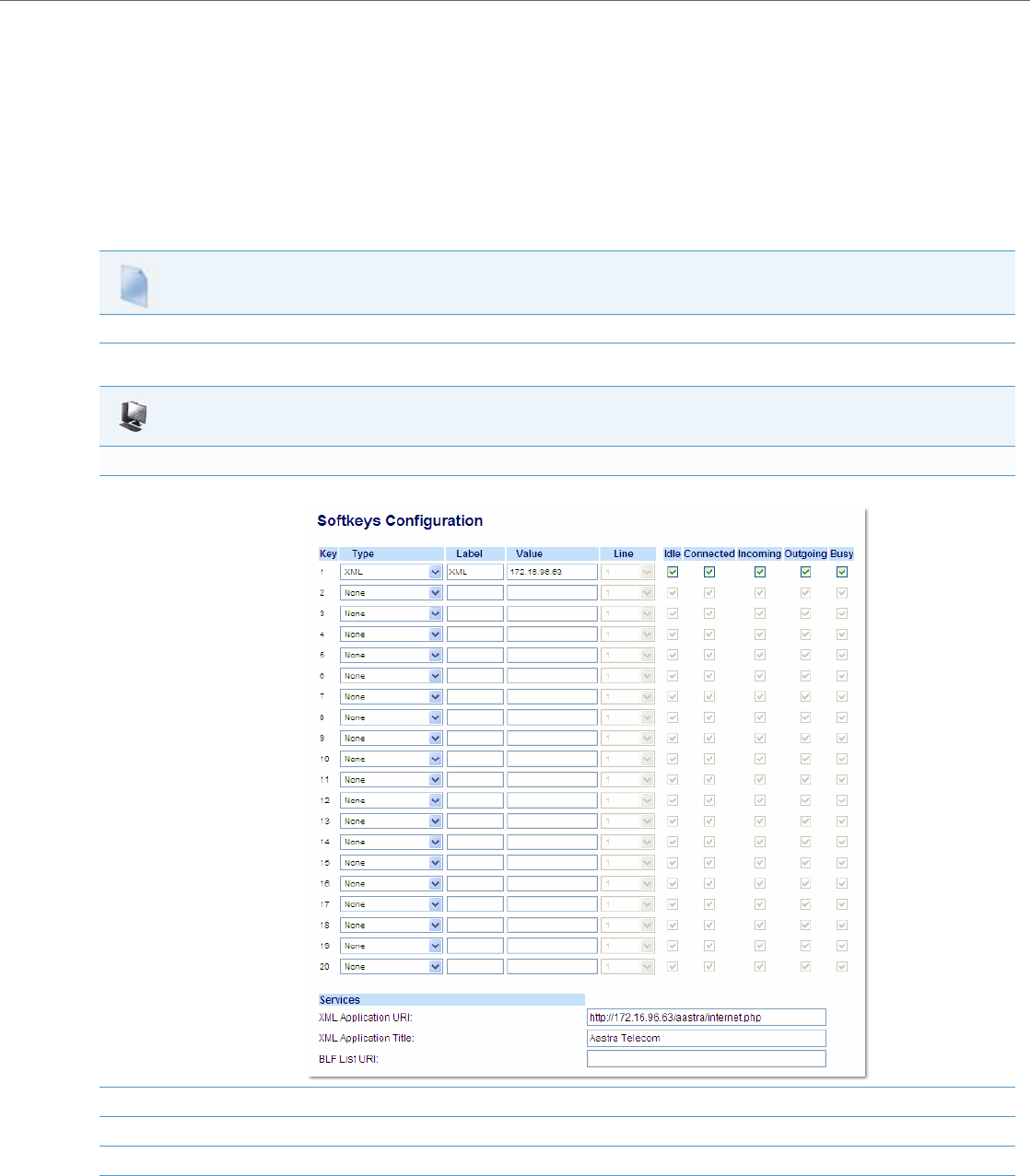
Operational Features
41-001343-02 REV04 – 05.2014 5-245
Example Configuration of XML Application
The following example shows the parameters you enter in the configuration files to configure an XML application:
xml application URI: http://172.16.96.63/aastra/internet.php
xml application title: Aastra Telecom
xml application post list: 10.50.10.53, dhcp10-53.ana.aastra.com
Configuring for XML on the IP Phone
After creating an XML application, an administrator can configure the IP phone to use the application using the configura-
tion files or the Aastra Web UI.
Configuration Files
For specific parameters you can set in the configuration files, see Appendix A, the section, “XML Settings” on pageA-114.
Aastra Web UI
For 8 and 11-Line LCD phones:
1. Click on Operation->Softkeys and XML.
2. Select a key from keys 1 through 20.
3. In the "Type" field, select XML from the list box.
4. In the "Label" field, enter a label that displays on the IP phone for the softkey. For example, "XML".
5. In the "Value" field, enter the IP address or qualified domain name of the XML application.
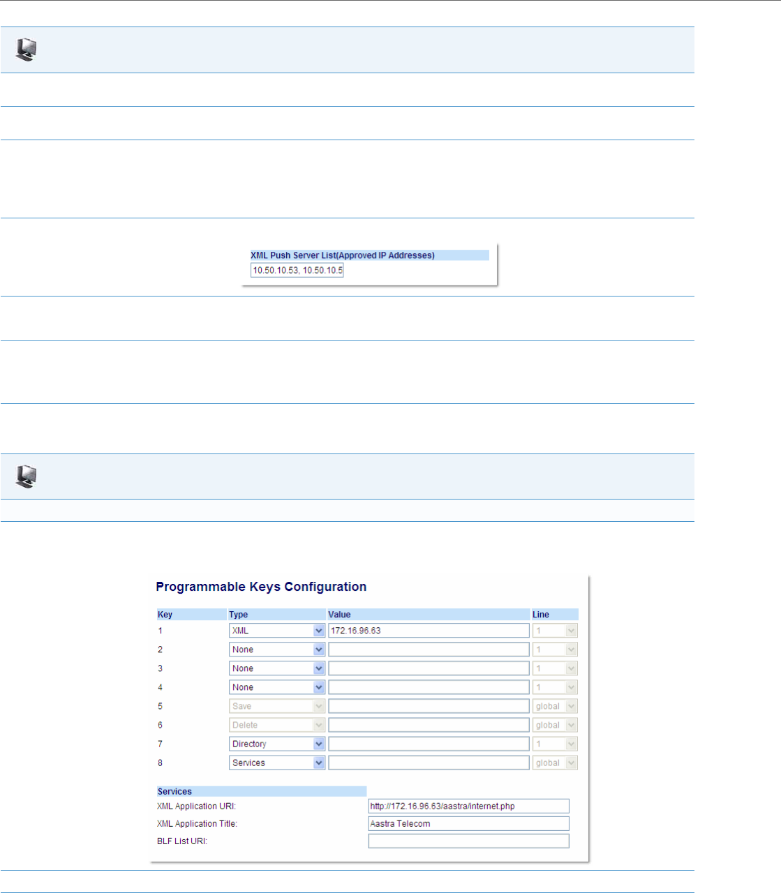
Operational Features
5-246 41-001343-02 REV04 – 05.2014
6. In the "XML Application URI" field, enter the HTTP server path or qualified domain name of the XML application you want to load to the IP
phone. For example, you could enter an XML application called "http://172.16.96.63/aastra/internet.php" in the applicable field.
7. In the "XML Application Title" field, enter the name of the XML application that you want to display on the IP phone Services Menu. In the
illustration above, the XML Application Title is "Aastra Telecom".
8. Click Save Settings to save your changes.
The XML application is applied to the IP phone immediately.
When the XML application is pushed to the phone via an HTTP POST, a host IP address or DNS server is required.
9. Click on Advanced Settings->Configuration Server.
10. In the "XML Push Server List (Approved IP Addresses)" field, enter the host IP address and/or DNS server. You can enter multiple IP address
and/or DNS servers (separated by commas). In the example in Step 8, the illustration shows a host IP address of "10.50.10.53, 10.50.10.54" in
the applicable field.
11. Click Save Settings to save your changes.
Note:
No posting is performed if a session times out.
Aastra Web UI
For 3-Line LCD phones:
1. Click on Operation->Programmable Keys.
6753i Screen
2. For 3-Line LCD phones, select an available key.
3. In the "Type" field, select XML from the list box.
Aastra Web UI
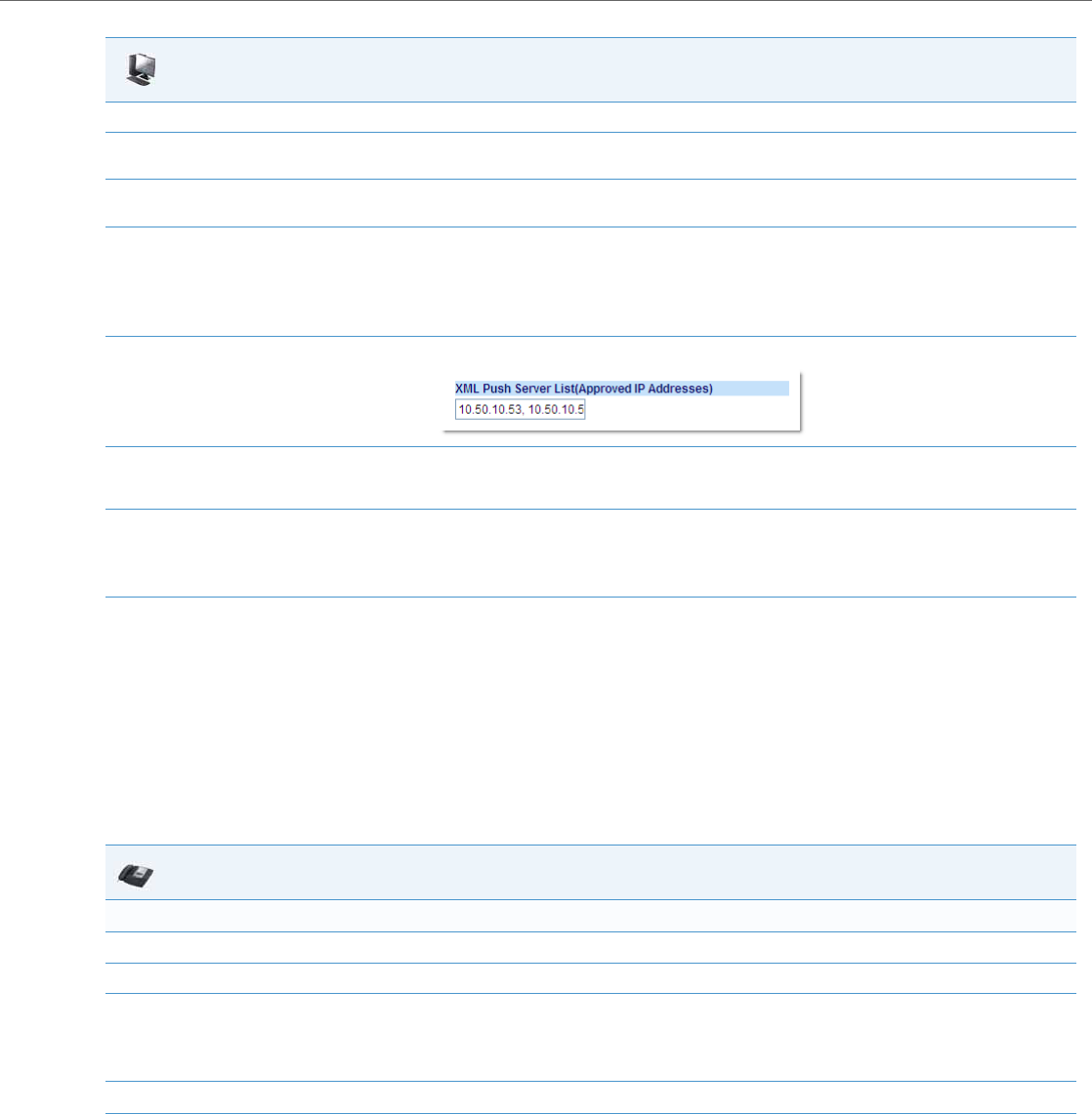
Operational Features
41-001343-02 REV04 – 05.2014 5-247
Using the XML Customized Service
After you create, save, and configure the IP phone with an XML application, the customized service is ready for you to use.
Reference
For more information about customizing the phones using XML objects, contact Aastra Customer Support regarding the
“Aastra XML Development Guide.”
Use the following procedure to use the XML feature on the IP phone.
4. In the "Value" field, enter the IP address or qualified domain name of the XML application.
5. In the "XML Application URI" field, enter the HTTP server path or qualified domain name of the XML application you want to load to the IP
phone. For example, you could enter an XML application called "http://172.16.96.63/aastra/internet.php" in the applicable field.
6. In the "XML Application Title" field, enter the name of the XML application that you want to display on the IP phone Services Menu. In the
illustration above, the XML Application Title is "Aastra Telecom".
7. Click Save Settings to save your changes.
The XML application is applied to the IP phone immediately.
When the XML application is pushed to the phone via an HTTP POST, a host IP address or DNS server is required.
8. Click on Advanced Settings->Configuration Server.
9. In the "XML Push Server List (Approved IP Addresses)" field, enter the host IP address and/or DNS server. You can enter multiple IP address
and/or DNS servers (separated by commas). In the example in Step 6, the illustration shows a host IP address of "10.50.10.53, 10.50.10.54" in
the applicable field.
10. Click Save Settings to save your changes.
Note:
No posting is performed if a session times out.
IP Phone UI
For 8 and 11-Line LCD phones:
1. Press the Services key on the phone to display the Services menu.
2. Select "Custom Features".
3. Use the 5 and 2 to scroll through the line items in a menu-driven and directory "Custom Features" screen.
Message services display to the screen after selecting the "Custom Features" option.
For user input services, follow the prompts as appropriate.
4. To exit from the "Custom Features" screen, press Exit.
Aastra Web UI
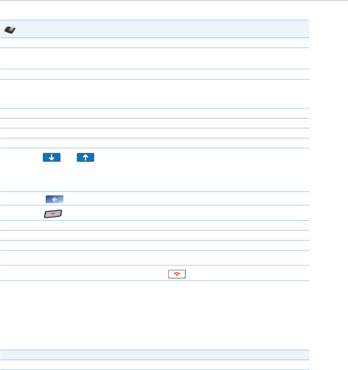
Operational Features
5-248 41-001343-02 REV04 – 05.2014
Action URIs
The IP phones have a feature that allows an administrator to specify a uniform resource identifier (URI) that triggers a GET
when certain events occur. The IP phone events that support this feature are:
The IP phones have a feature that allows an administrator to specify a uniform resource identifier (URI) that triggers a GET
when certain XML events occur. The Action URI feature prevents the phones from hanging if the Action URIs should fail.
The phones also support transparent, non-blocking, XML post execute item URIs.
The IP phone XML events that support this feature are defined in the following table.
IP Phone UI
For 3-Line LCD phones:
1. Press the programmable key configured on the phone for XML services.
A "Custom Features" screen displays.
2. Use the 5 and 2 to scroll through the customized features.
3. Select a service to display the information for that customized service.
Message services display to the screen after pressing the programmable key.
For user input services, follow the prompts as appropriate.
4. To exit from the "Custom Features" screen, press the XML programmable key again.
For the 6739i:
1. Press Services key on the phone.
2. Press "Custom Features".
3. Use the and keys to scroll through the line items in a menu-driven and directory
"Custom Features" screen.
Message services display to the screen after selecting the "Custom Features" option.
For user input services, follow the prompts as appropriate.
4. Press the to return to the previous screen.
5. Press the button at any time to return to the idle screen.
For the 6739i:
1. Press the XML softkey on the 6867i phone. An XML screen displays.
2. Use the 5 and 2 to scroll through the customized features.
3. For menu and directory services, select a service to display the information for that customized service. Message services display to the
screen after pressing the respective key. For user input services, follow the on-screen prompts.
4. To exit from the XML screen, press the XML softkey again or press the button.
Action URI Description
Startup Specifies the URI for which the phone executes a GET on when a startup event occurs.
Successful Registration Specifies the URI for which the phone executes a GET on when a successful registration event
occurs.

Operational Features
41-001343-02 REV04 – 05.2014 5-249
The following table identifies the configurable action URI parameters in the configuration files and the Aastra Web UI. This
table also identifies the variables that apply to specific parameters.
Action URIs and Associated Variables
Registration Event Specifies the URI for when registration events occur or when there are registration state
changes.
Note:
This action URI is not called when the same event is repeated (for example, a timeout occurs
again when registration is already in a timeout state.)
Incoming Call Specifies the URI for which the phone executes a GET on when an incoming call event occurs.
Outgoing Call Specifies the URI for which the phone executes a GET on when an outgoing call event occurs.
Offhook Specifies the URI for which the phone executes a GET on when an offhook event occurs.
Onhook Specifies the URI for which the phone executes a GET on when an onhook event occurs.
Connected Specifies the URI for which the phone executes an HTTP GET when it goes into the “connected”
state. This includes regular phone calls, intercom calls, paging calls, RTP streaming, and the
playing of a WAV file. It is also triggered when the phone establishes the second leg of a 3-way
call. For more information, see “Action URI Connected” on page5-253.
Disconnected Specifies the URI that the phone executes a GET on, when it transitions from the incoming,
outgoing, calling, or connected state into the idle state. For more information, see “Action URI
Disconnected” on page5-254.
XML SIP Notify Specifies the URI to be called when an empty XML SIP NOTIFY is received by the phone. For
more information, see “XML SIP Notify Events” on page5-256.
Poll Specifies the URI to be called every "action uri poll interval" seconds. For more information, see
“Polling Action URIs” on page5-252.
Poll Interval Specifies the interval, in seconds, between calls from the phone to the "action uri poll". For
more information, see “Polling Action URIs” on page5-252.
Note:
For more information about the XML execute items, see the Aastra XML Developer’s Guide.
Configuration File Param-
eters Aastra Web UI Parameters at Advanced Set-
tings->Action URI Applicable Variables
action uri startup Startup $$DISPLAYNAME$$
$$SIPUSERNAME$$
$$SIPAUTHNAME$$
$$PROXYURL$$
$$LINESTATE$$
$$LOCALIP$$
$$REGISTRATIONSTATE$$
$$REGISTRATIONCODE$$
action uri registered Successful Registration $$SIPUSERNAME$$
$$SIPAUTHNAME$$
$$PROXYURL$$
$$LINESTATE$$
$$LOCALIP$$
action uri registration event Registration Event $$REGISTRATIONSTATE$$
$$REGISTRATIONCODE$$
Action URI Description

Operational Features
5-250 41-001343-02 REV04 – 05.2014
Variable Descriptions
The following table provides a description of each variable.
action uri incoming Incoming Call $$REMOTENUMBER$$
$$DISPLAYNAME$$
$$SIPUSERNAME$$
$$INCOMINGNAME$
$$LINESTATE$$
$$CALLDURATION$$
$$CALLDIRECTION$$
$$LOCALIP$$
action uri outgoing Outgoing Call $$REMOTENUMBER$$
$$SIPUSERNAME$$
$$LINESTATE$$
$$LOCALIP$$
action uri offhook Offhook $$LINESTATE$$
$$LOCALIP$$
action uri onhook Onhook $$LOCALIP$$
$$CALLDURATION$$
$$CALLDIRECTION$$
$$LINESTATE$$
action uri connected Connected $$REMOTENUMBER$$
$$DISPLAYNAME$$
$$SIPUSERNAME$$
$$SIPAUTHNAME$$
$$INCOMINGNAME$
$$PROXYURL$$
$$LINESTATE$$
$$LOCALIP$$
$$DISPLAYNAME$$
$$CALLDURATION$$
$$CALLDIRECTION$$
$$REGISTRATIONSTATE$$
$$REGISTRATIONCODE$$
action uri disconnected Disconnected $$LINESTATE$$
$$LOCALIP$$
For more information, see “Action URI Disconnected” on page5-254.
action uri xml sip notify XML SIP Notify $$LOCALIP$$
For more information, see “XML SIP Notify Events” on page5-256.
action uri poll Poll For more information, see “Polling Action URIs” on page5-252.
action uri poll interval Interval For more information, see “Polling Action URIs” on page5-252.
Variable Description
$$SIPUSERNAME$$ Username associated with:
•registered phone
•incoming caller
•outgoing caller
$$SIPAUTHNAME$$ Authentication name associated with:
•registered phone
$$PROXYURL$$ Proxy URL associated with:
•registered phone
Configuration File Param-
eters Aastra Web UI Parameters at Advanced Set-
tings->Action URI Applicable Variables

Operational Features
41-001343-02 REV04 – 05.2014 5-251
How it Works
When a startup, successful registration, incoming call, outgoing call, offhook, or onhook call event occurs on the phone,
the phone checks to see if the event has an action URI configured. If the phones finds a URI configured, any variables con-
figured (in the form $$VARIABLENAME$$) are replaced with the value of the appropriate variable. After all of the variables
are bound, the phone executes a GET on the URI. The Action URI binds all variables and is not dependant on the state of
the phone.
For example, if you enter the following string for the action uri outgoing parameter:
action uri outgoing: http://10.50.10.140/outgoing.pl?number=$$REMOTENUMBER$$
$$LINESTATE$$ Current line state associated with:
•registered phone
•incoming caller
•outgoing caller
•offhook
•onhook
•disconnected
$$LOCALIP$$
Note:
This variable allows for enhanced informa-
tion in call records and billing applications.
IP Address associated with:
•registered phone
•onhook
$$REMOTENUMBER$$ Remote number associated with:
•incoming caller
•outgoing caller
$$DISPLAYNAME$$ Display name associated with:
•incoming caller
$$SIPUSERNAME$$ Username associated with:
•registered phone
•incoming caller
•outgoing caller
$$INCOMINGNAME$$ Name associated with:
•incoming caller
$$CALLDURATION$$
Note:
This variable allows for enhanced informa-
tion in call records and billing applications.
Duration of last call. This variable is associated with:
•onhook
$$CALLDIRECTION$$
Note:
This variable allows for enhanced informa-
tion in call records and billing applications.
Specifies whether the current/last call was incoming or outgoing. This variable is associated with:
•onhook
$$REGISTRATIONSTATE$$ Specifies the state of the phone’s registration. Registration states can be:
•registered
•unregistered
•expired
•refused
•timeout
$$REGISTRATIONCODE$$ Specifies the code generated during the registration process.
Registration code can be:
"xxx"
where xxx is the 3 digit code; for example, "403". Possible codes are:
•001 (registration successful)
•403 (registration failed)
Variable Description
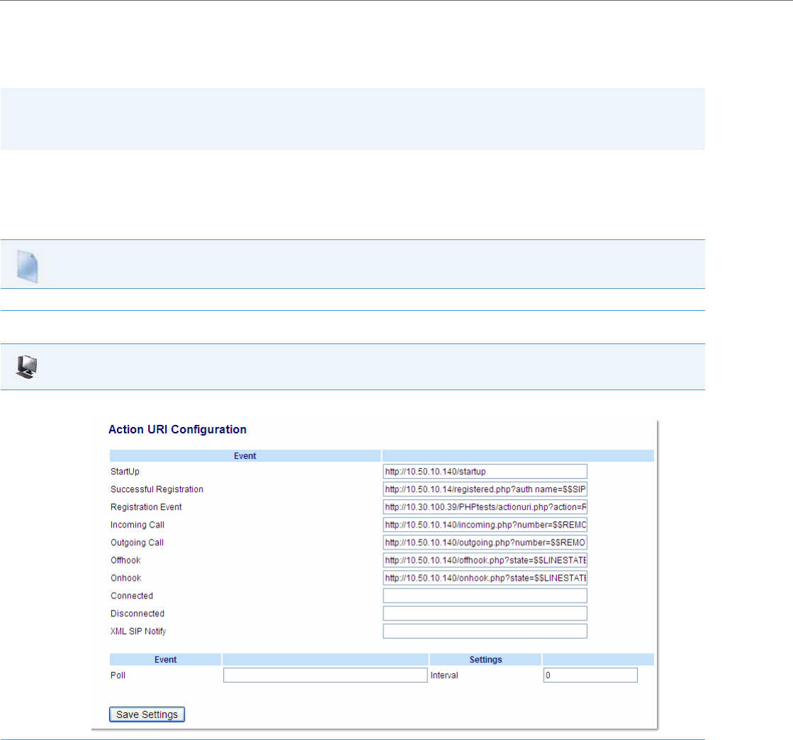
Operational Features
5-252 41-001343-02 REV04 – 05.2014
and you dial out the number 5551212, the phone executes a GET on:
http://10.50.10.140/outgoing.pl?number=5551212
You can configure this feature via the configuration files or the Aastra Web UI.
Configuring XML Action URIs
Use the following procedures to configure XML Action URIs using the configuration files or the Aastra Web UI.
Note:
If the phone cannot find the Action URI you specify, it returns a “NULL” response. For example,
http://10.50.10.140/outgoing.pl?number=
Configuration Files
For specific parameters you can set in the configuration files, see Appendix A, the section, “Action URI Settings” on pageA-116.
Aastra Web UI
1. Click on Advanced Settings->Action URI.
2. Enter an XML URI for a startup event in the “Startup” field. For example:
http://10.50.10.140/startup
This parameter specifies the URI for which the phone executes a GET on when a startup event occurs.

Operational Features
41-001343-02 REV04 – 05.2014 5-253
3. Enter an XML URI for a successful registration in the “Successful Registration” field. For example:
http://10.50.10.14/registered.php?auth name=$$SIPAUTHNAME$$
This parameter specifies the URI for which the phone executes a GET on when a successful registration event occurs.
Note:
For a successful registration event, use the associated variables indicated in the table “Action URIs and Associated Variables” on page5-247.
The “Successful Registration” parameter executes on the first successful registration of each unique line configured on the phone.
4. Enter an XML URI in the “Registration Event” field, for when the phone performs registration. For example:
http://10.30.100.39/PHPtests/actionuri.php?action=RegEvt®state=$$REGISTRATIONSTATE$$®code=$$REGISTRATIONCODE$$
This parameter specifies the URI that the phone executes a GET on, when a registration event change occurs.
Note:
For a registration event, use the associated variables indicated in the table “Action URIs and Associated Variables” on page5-247.
5. Enter an XML URI for an incoming call event in the “Incoming Call” field. For example:
http://10.50.10.140/incoming.php?number=$$REMOTENUMBER$$
This parameter specifies the URI for which the phone executes a GET on when an incoming call event occurs.
Note:
For an incoming call event, use the associated variables indicated in the table “Action URIs and Associated Variables” on page5-247.
6. Enter an XML URI for an outgoing call event in the “Outgoing Call” field. For example:
http://10.50.10.140/outgoing.php?number=$$REMOTENUMBER$$
This parameter specifies the URI for which the phone executes a GET on when an outgoing call event occurs.
Note:
For an outgoing call event, use the associated variables indicated in the table “Action URIs and Associated Variables” on page5-247.
7. Enter an XML URI for an offhook event in the “Offhook” field. For example:
http://10.50.10.140/offhook.php?state=$$LINESTATE$$
This parameter specifies the URI for which the phone executes a GET on when an offhook event occurs.
Note:
For an offhook event, use the associated variables indicated in the table “Action URIs and Associated Variables” on page5-247.
8. Enter an XML URI for an onhook event in the “Onhook” field. For example:
http://10.50.10.140/onhook.php?state=$$LINESTATE$$
This parameter specifies the URI for which the phone executes a GET on when an onhook event occurs.
Note:
For an onhook event, use the associated variables indicated in the table “Action URIs and Associated Variables” on page5-247.
9. To configure a Connected event, see the section, “Action URI Connected” on page5-253.
10. To configure a Disconnected event, see the section, “Action URI Disconnected” on page5-254.
11. To configure an XML SIP Notify event, see the section, “XML SIP Notify Events” on page5-256.
Aastra Web UI
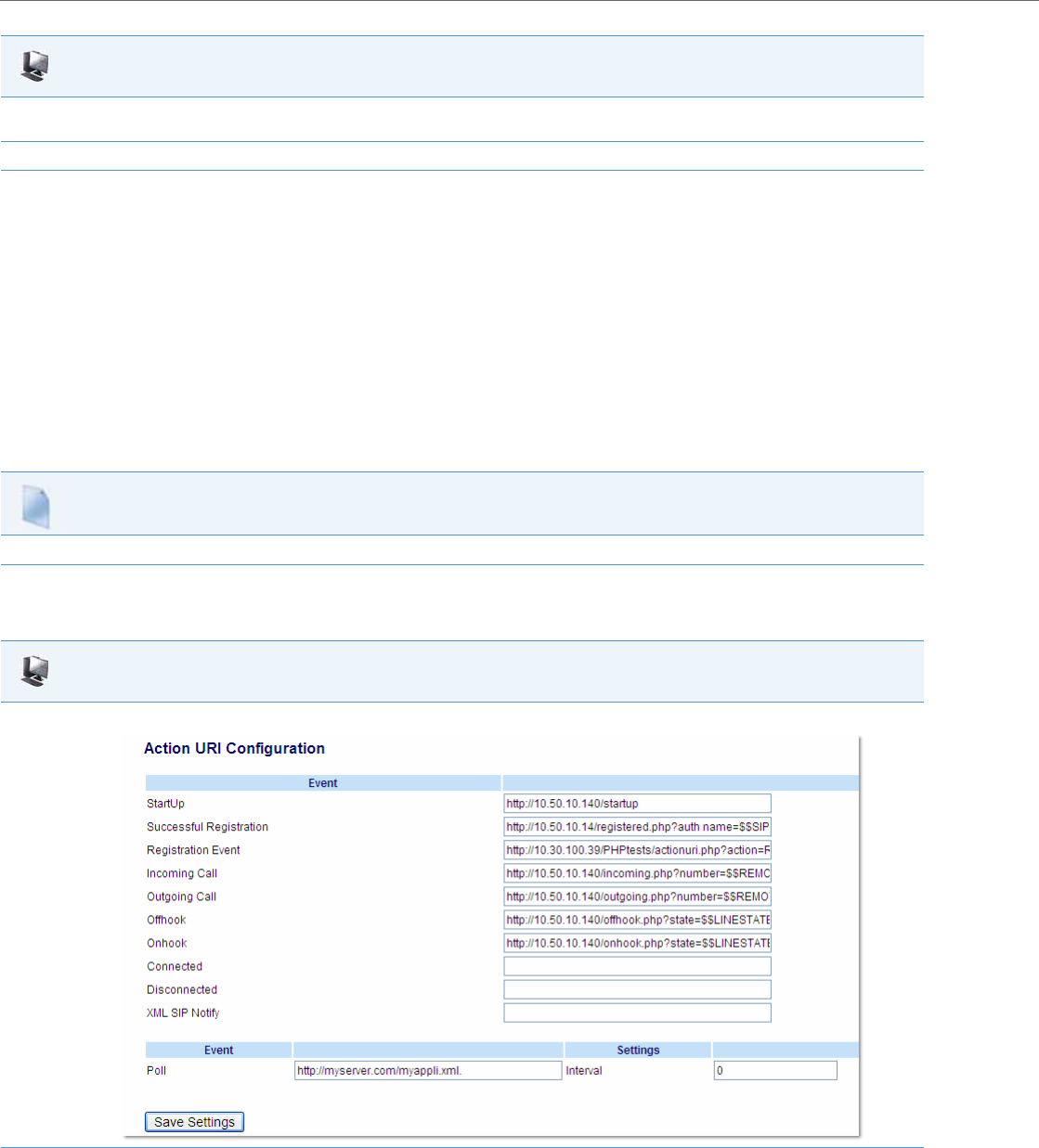
Operational Features
5-254 41-001343-02 REV04 – 05.2014
Polling Action URIs
Another way to reach a phone behind a NAT/firewall is to have the phone make an XML call at periodic intervals. An
Administrator can use the action uri poll parameter that commands the phone to perform an XML call at configurable
intervals.
An Administrator can specify the URI to be called and specify the interval between polls using the configuration files or
the Aastra Web UI. Configuration of this feature is dynamic (no reboot required).
Configuring Polling Action URI via the Configuration Files
Use the following parameters to configure the polling Action URI on the IP Phones.
•action uri poll
•action uri poll interval
Configuring Polling Action URI via the Aastra Web UI
Use the following procedure to configure polling Action URI using the Aastra Web UI.
12. (Optional) You can poll a URI at specific intervals on the phones. For more information about polling Action URIs, see “Polling Action URIs”
on page5-252.
13. Click Save Settings to save your changes.
Configuration Files
For the specific parameter you can set in the configuration files, see Appendix A, the section, “Polling Action URI Settings” on pageA-119.
Aastra Web UI
1. Click on Advanced Settings->Action URI.
2. In the “Poll” field, enter a URI to be called every "action uri pool interval" seconds. Enter the value in a URI format. For example,
http://myserver.com/myappli.xml.
Aastra Web UI

Operational Features
41-001343-02 REV04 – 05.2014 5-255
Action URI Connected
A parameter called “action uri connected” (configuration files) and “Connected” (Aastra Web UI) now allows XML scripts
to determine when a call is connected. When enabled, the phone triggers an HTTP GET when it goes into the “connected”
state. This includes regular phone calls, intercom calls, paging calls, RTP streaming, and the playing of a WAV file. It is also
triggered when the phone establishes the second leg of a 3-way call.
This parameter can use the following variables:
•$$REMOTENUMBER$$
•$$DISPLAYNAME$$
•$$SIPUSERNAME$$
•$$SIPAUTHNAME$$
•$$INCOMINGNAME$
•$$PROXYURL$$
•$$LINESTATE$$
•$$CALLDIRECTION$$
•$$LOCALIP$$
•$$DISPLAYNAME$$
•$$CALLDURATION$$
•$$REGISTRATIONSTATE$$
•$$REGISTRATIONCODE$$
If the Administrator enables this feature (by specifying a connect URI), when a call is connected, the phone checks to see if
the event has a Connect URI configured. If the phones finds a configured URI it executes an XML script or the variable if
defined.
Example
In the configuration files, you can enter the following:
action uri connected: http://www.example.com/connect.php
An Administrator can enable the “Connected” Action URI feature using the configuration files or the Aastra Web UI.
Limitations
•During SLA calls, the phone uses the Action URI Connected parameter when the line is seized before the caller dials out.
•SCA and BLA calls on hold trigger the Action URI Connected parameter, since the retrieval is a 2nd call by the phone,
and the phone cannot link the retrieved call with the earlier held call.
For more information about the XML API objects, see the Aastra XML Developers Guide.
Configuring the Action URI Connected Feature
Use the following procedure to configure the Action URI Connected feature on the phone.
3. In the “Interval” field, enter the interval, in seconds, between calls from the phone to the "action uri poll". The value of “0” is disabled.
4. Click Save Settings to save your changes.
Configuration Files
For specific parameters you can set in the configuration files, see Appendix A, the section, “Action URI Settings” on pageA-116.
Aastra Web UI
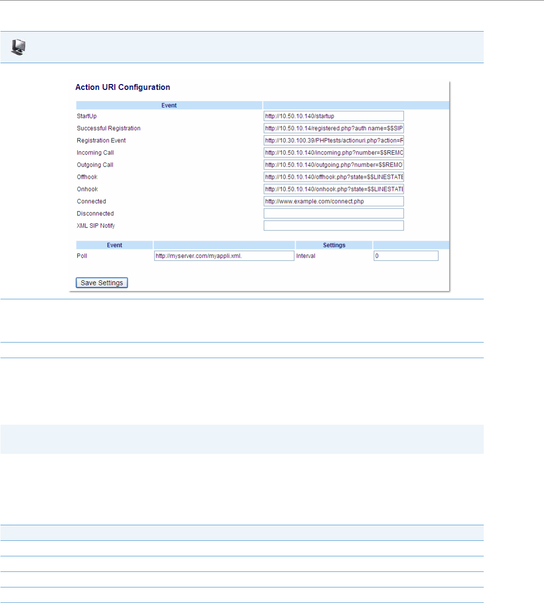
Operational Features
5-256 41-001343-02 REV04 – 05.2014
Action URI Disconnected
The phones have a parameter, “action uri disconnected” that allow a disconnect event to occur when the phone transi-
tions from any active state (outgoing, incoming, connected, or calling) to an idle state. This parameter can use the varia-
ble “$$LINESTATE$$”.
If the Administrator enables this feature (by specifying a disconnect URI), when a call is disconnected, the phone checks
to see if the event has a Disconnect URI configured. If the phones finds a configured URI with a $$LINESTATE$$ variable,
it replaces the $$LINESTATE$$ variable with the appropriate line state of the current active line. After all of the variables
are bound, the phone executes a GET on the URI. The following table lists the applicable values for the $$LINESTATE$$
variable.
Aastra Web UI
1. Click on Advanced Settings->Action URI.
2. In the “Connected” field, enter a valid URI for which the phone executes a GET on, when it goes into the “connected” state. Leaving this field
empty disables the Action URI Connected feature. For example,
http://www.example.com/connect.php
3. Click Save Settings to save your settings.
Note:
The $$LINESTATE$$ variable is optional and not required when enabling the “action uri disconnected” parameter.
$$LINESTATE$$ Value Description Meaning in a Disconnected URI
IDLE Phone is idle. N/A
DIALING Phone is offhook and ready to dial. N/A
CALLING A SIP INVITE was sent but no response was received. Error occurred during the call.
OUTGOING Remote party is ringing. Call was cancelled.
INCOMING Local phone is ringing. Call was missed or cancelled.

Operational Features
41-001343-02 REV04 – 05.2014 5-257
The Action URI Disconnect feature allows an Administrator to determine the reason for the disconnect if required.
Example
If you enter the following string on Phone A for the “action uri disconnected” parameter:
action uri disconnected: http://fargo.ana.aastra.com/disconnected.xml?state=$$LINESTATE$$
and then Phone A calls Phone B, Phone B answers and then hangs up, Phone A executes a GET on:
http://fargo.ana.aastra.com/disconnected.xml?state=CONNECTED
which is what the remote server receives.
An Administrator can enable the disconnect feature using the configuration files or the Aastra Web UI.
Configuring the Action URI Disconnected Feature
Use the following procedure to configure the Action URI Disconnected feature on the phone.
CONNECTED Parties are talking. Call was successful.
CLEARING Call was released but not acknowledged. N/A
Note:
If you enable the Action URI Disconnect feature by specifying a URI, the URI is called when any disconnect event occurs
including an intercom call or a conference setup.
Note:
If the phone can’t find the Action URI you specify, it returns a “NULL” response. For example,
http://fargo.ana.aastra.com/disconnected.xml?state=
Configuration Files
For specific parameters you can set in the configuration files, see Appendix A, the section, “Action URI Settings” on pageA-116.
$$LINESTATE$$ Value Description Meaning in a Disconnected URI
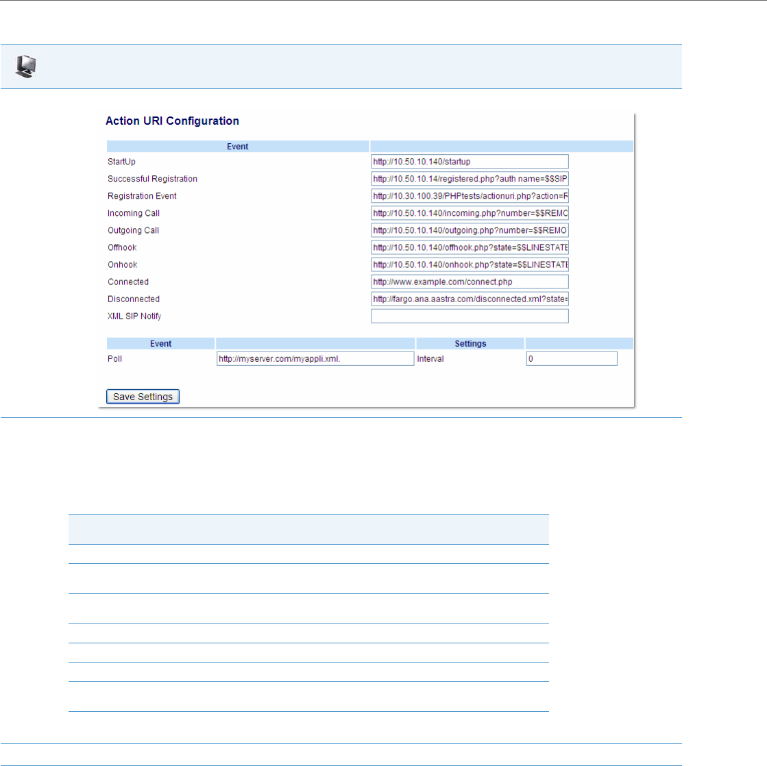
Operational Features
5-258 41-001343-02 REV04 – 05.2014
XML SIP Notify Events
In order for an XML push to bypass the NAT/firewall, the phone supports a proprietary SIP NOTIFY event (aastra-xml) with
or without XML content. An Administrator can enable/disable the SIP NOTIFY event using a specific parameter in the
configuration files (sip xml notify event) or the Aastra Web UI (XML SIP Notify).
If XML content is provided in the SIP NOTIFY, it is processed directly by the phone as it is done for an XML PUSH.
Aastra Web UI
1. Click on Advanced Settings->Action URI->Event.
2. In the “Disconnected” field, enter a valid URI for which the phone executes a GET on, when it transitions from the incoming, outgoing, call-
ing, or connected state into the idle state. Leaving this field empty disables the Action URI Disconnected feature. For example,
http://fargo.ana.aastra.com/disconnected.xml?state=$$LINESTATE$$
The following table lists the applicable values and descriptions for the $$LINESTATE$$.
3. Click Save Settings to save your settings.
$$LINESTATE$$ Value Description Meaning in a
Disconnected URI
IDLE Phone is idle. N/A
DIALING Phone is offhook and ready to
dial. N/A
CALLING A SIP INVITE was sent but no
response was received. Error occurred during the call.
OUTGOING Remote party is ringing. Call was cancelled.
INCOMING Local phone is ringing. Call was missed or cancelled.
CONNECTED Parties are talking. Call was successful.
CLEARING Call was released but not
acknowledged. N/A

Operational Features
41-001343-02 REV04 – 05.2014 5-259
If the content is empty in the SIP NOTIFY, the phone automatically triggers a new pre-configured action uri (action uri xml
sip notify).
Example of a SIP NOTIFY with XML Content
NOTIFY sip:200@10.30.100.103:5060 SIP/2.0
Via: SIP/2.0/UDP 10.30.100.103:5060;branch=z9hG4bK7bbc1fac;rport
From: <sip:201@10.30.100.103:5060>;tag=81be2861f3
To: Jacky200 <sip:200@10.30.100.103:5060>
Contact: <sip:201@10.30.100.103>
Call-ID: 59638f5d95c9d301
CSeq: 4 NOTIFY
Max-Forwards: 70
Event: aastra-xml
Content-Type: application/xml
Content-Length: 115
<AastraIPPhoneExecute><ExecuteItem URI="http://10.30.100.39/XMLtests/SampleText-
Screen.xml"/></AastraIPPhoneExecute>
When the phone receives the SIP NOTIFY, the XML content is processed as any XML object. In the above example, the
phone calls http://10.30.100.39/XMLtests/SampleTextScreen.xml after reception of the SIP NOTIFY.
Example of a SIP NOTIFY without XML Content
NOTIFY sip:200@10.30.100.103:5060 SIP/2.0
Via: SIP/2.0/UDP 10.30.100.103:5060;branch=z9hG4bK7bbc1fac;rport
From: <sip:201@10.30.100.103:5060>;tag=81be2861f3
To: Jacky200 <sip:200@10.30.100.103:5060>
Contact: <sip:201@10.30.100.103>
Call-ID: 59638f5d95c9d301
CSeq: 4 NOTIFY
Max-Forwards: 70
Event: aastra-xml
Content-Type: application/xml
Content-Length: 0
When the phone receives the SIP NOTIFY, it will trigger the action uri xml sip notify parameter, if it has been previously
configured using the configuration files or the Aastra Web UI. If the action uri xml sip notify parameter is not configured,
the phone does not do anything.
On the phone side, a System Administrator can enable or disable this SIP NOTIFY feature using the configuration files or
the phone Web UI.
Note:
The phone supports all the current XML objects with all the existing limitations. For example if an AastraIPPhoneExe-
cute is used, the embedded URI(s) can not be HTTPS based.
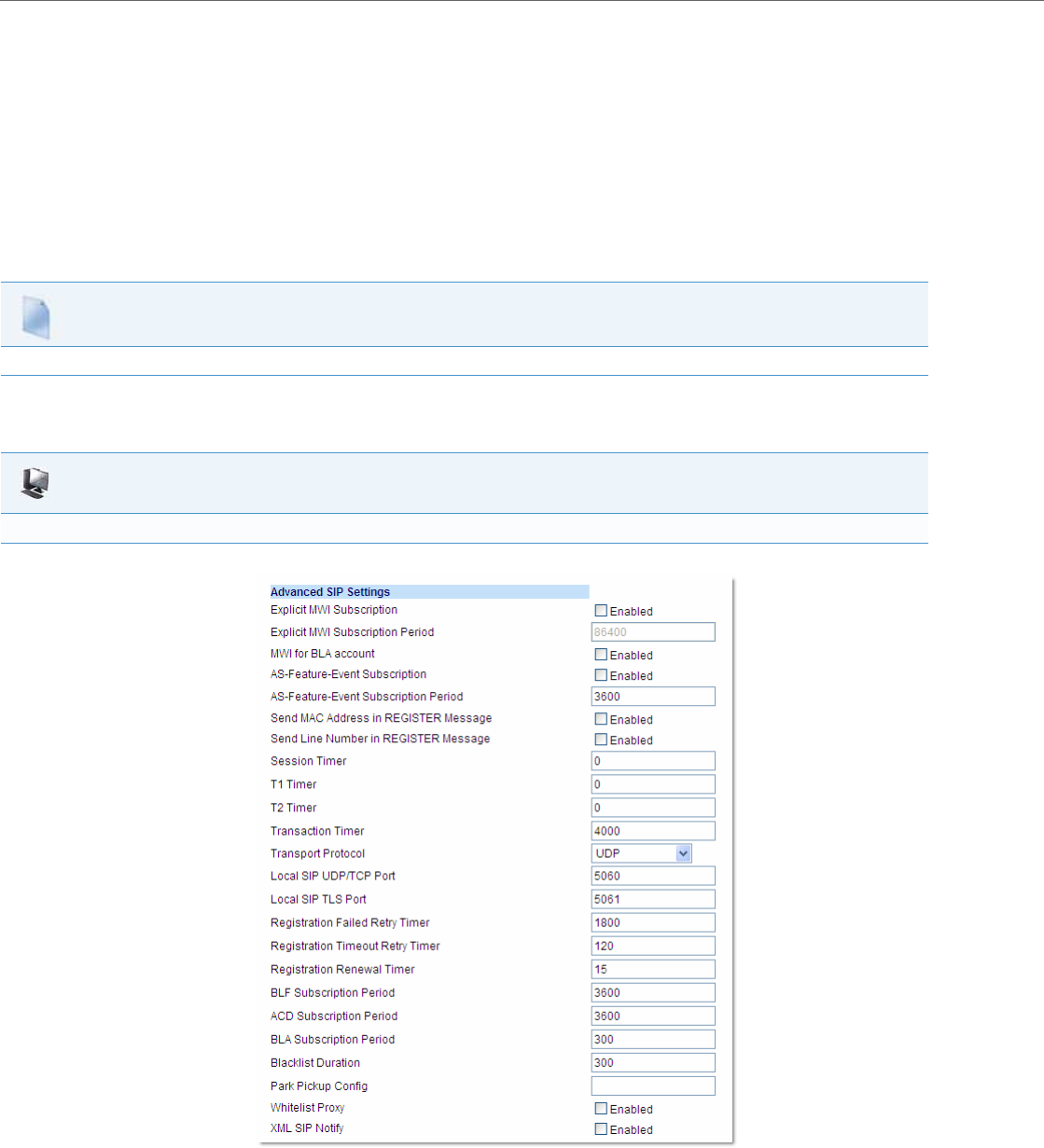
Operational Features
5-260 41-001343-02 REV04 – 05.2014
Also to ensure that the SIP NOTIFY is coming from a trusted source, it is recommended that you enable the Whitelist fea-
ture (Whitelist Proxy parameter) on the IP phone. If enabled, and the phone receives a SIP NOTIFY from a server that is
NOT on the whitelist, the phone rejects the message.
Enabling/Disabling XML SIP NOTIFY using the Configuration Files
To enable/disable the SIP NOTIFY event, you can set the following parameter in the configuration files:
•sip xml notify event
If the content is missing in the SIP NOTIFY message received by the phone, the phone automatically uses the value you
specify for the following parameter:
•action uri xml sip notify
Enabling/Disabling XML SIP NOTIFY Using the Aastra Web UI
Use the following procedure to enable/disable the XML SIP NOTIFY feature in the Aastra Web UI.
Configuration Files
For the specific parameter you can set in the configuration files, see Appendix A, the section, “Polling Action URI Settings” on pageA-119.
Aastra Web UI
Enabling/Disabling the XML SIP NOTIFY Feature
1. Click on Advanced Settings->Global SIP->Advanced SIP Settings.
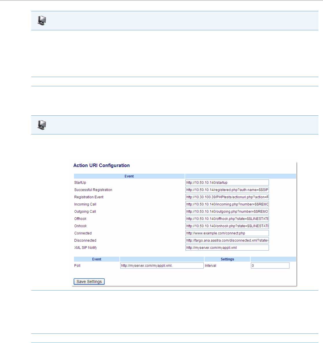
Operational Features
41-001343-02 REV04 – 05.2014 5-261
Configuring XML SIP NOTIFY using the Aastra Web UI if an Empty SIP NOTIFY Message Received by the Phone
Use the following procedure in the Aastra Web UI to configure the XML SIP NOTIFY parameter when the phone receives an
empty SIP NOTIFY message.
XML Softkey URI
In addition to specifying variables for the Action URIs, you can also specify variables in the XML softkey URIs that are
bound when the key is pressed. These variables are the same as those used in the Action URIs.
2. The “XML SIP Notify" field is disabled by default. To enable this field, check the box.
This field enables or disables the phone to accept or reject an aastra-xml SIP NOTIFY message.
Note:
To ensure the SIP NOTIFY is coming from a trusted source, it is recommended that you enable the Whitelist feature (Whitelist Proxy param-
eter) on the IP phone. If enabled, and the phone receives a SIP NOTIFY from a server that is NOT on the whitelist (i.e. untrusted server), the
phone rejects the message.
3. Click Save Settings to save your changes.
Aastra Web UI
1. If the content is missing in the SIP NOTIFY message received by the phone, the phone automatically uses the value you specify for the Action
URI XML SIP Notify parameter at the path Advanced Settings->Action URI.
Click on Advanced Settings->Action URI.
2. Specify a URI to be called when an empty XML SIP NOTIFY is received by the phone.
For example:
http://myserver.com/myappli.xml
Note:
The sip xml notify event parameter at the path Advanced Settings->Global SIP->Advanced SIP Settings must be enabled.
3. Click Save Settings to save your changes.
Aastra Web UI

Operational Features
5-262 41-001343-02 REV04 – 05.2014
When an administrator enters an XML softkey URI either via the Aastra Web UI or the configuration files, they can specify
the following variables:
•$$SIPUSERNAME$$
•$$SIPAUTHNAME$$
•$$PROXYURL$$
•$$LINESTATE$$
•$$LOCALIP$$
•$$REMOTENUMBER$$
•$$DISPLAYNAME$$
•$$SIPUSERNAME$$
•$$INCOMINGNAME$$
•$$CALLDURATION$$
•$$CALLDIRECTION$$
When the softkey is pressed, if the phone finds a URI configured with variables (in the form $$VARIABLENAME$$), they
are replaced with the value of the appropriate variable. After all of the variables are bound, the softkey executes a GET on
the URI.
Example
For example, if the administrator specifies an XML softkey with the value:
http://10.50.10.140/script.pl?name=$$SIPUSERNAME$$
This softkey executes a GET on:
http://10.50.10.140/script.pl?name=42512
assuming that the sip username of the specific line is 42512.
You can configure the XML softkey URI variables via the configuration files or the Aastra Web UI.
Configuring XML Softkey URIs
Use the following procedures to configure XML Softkey URIs using the configuration files or the Aastra Web UI.
Note:
For a description of each variable in the above list, see “Variable Descriptions” on page5-248.
Configuration Files
For specific parameters you can set in the configuration files, see Appendix A, the section,“Softkey/Programmable Key/Keypad Key/Feature
Key/Expansion Module Key/Hard Key Parameters” on pageA-156.
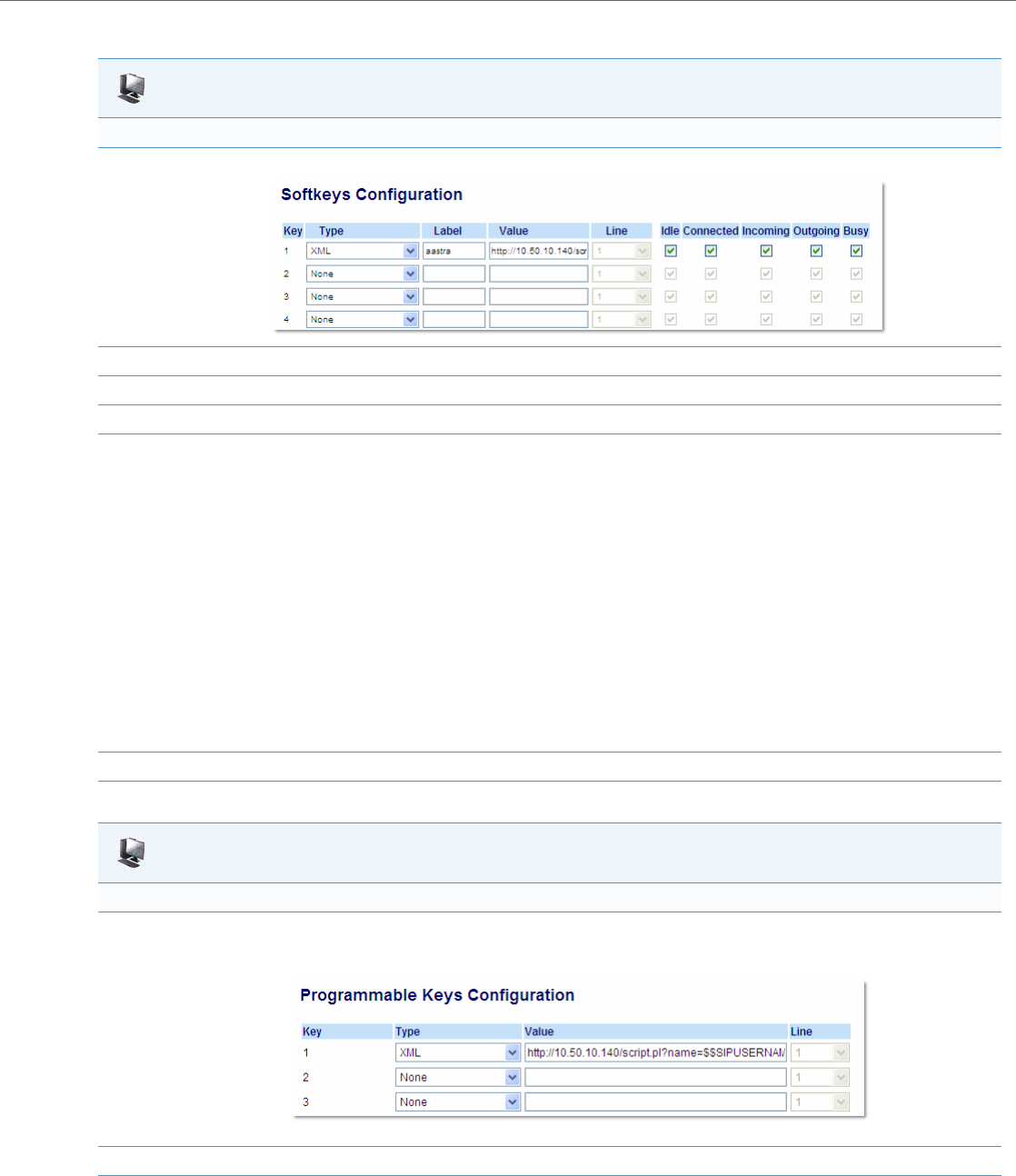
Operational Features
41-001343-02 REV04 – 05.2014 5-263
Aastra Web UI
For 8 and 11-Line LCD phones:
1. Click on Operation->Softkeys and XML.
2. Select a key from keys 1 through 20.
3. In the "Type" field, select XML from the list box.
4. In the "Label" field, enter a label that displays on the IP phone for the XML softkey. For example, "aastra".
5. In the "Value" field, enter the URI that the phone performs a GET on when the key is pressed. For example:
http://10.50.10.140/script.pl?name=$$SIPUSERNAME$$
Note:
You can use the following variables in the URI:
•$$SIPUSERNAME$$
•$$SIPAUTHNAME$$
•$$PROXYURL$$
•$$LINESTATE$$
•$$LOCALIP$$
•$$REMOTENUMBER$$
•$$DISPLAYNAME$$
•$$SIPUSERNAME$$
•$$INCOMINGNAME$$
•$$CALLDURATION$$
•$$CALLDIRECTION$$
6. Click Save Settings to save your changes.
Aastra Web UI
For 3-Line LCD phones:
1. Click on Operation->Programmable Keys.
6753i Screen
2. On 3-Line LCD phones, select an available key.
3. In the "Type" field, select XML from the list box.

Operational Features
5-264 41-001343-02 REV04 – 05.2014
XML Key Redirection
The IP phones allow the redirecting of phone-based hard keys to XML scripts. This allows the server to provide the phone
with Redial, Transfer (Xfer), Conference (Conf), and Intercom (Icom) key features, and the Voicemail option feature, rather
then accessing them from the phone-side. This feature allows you to access the redirected keys and voicemail option
from the server using the IP Phone’s Services Menu. By default, the server-side keys function the same as the phone-side
key features.
The following table identifies the phone states that apply to each key redirection.
The following URI configuration parameters control the redirection of the keys and the voicemail option:
•redial script
•xfer script
•conf script
•icom script
•voicemail script
An Administrator can configure the XML key, redirection URI parameters using the configuration files only.
4. In the "Value" field, enter the URI that the phone performs a GET on when the key is pressed. For example:
http://10.50.10.140/script.pl?name=$$SIPUSERNAME$$
Note:
You can use the following variables in the URI:
•$$SIPUSERNAME$$
•$$SIPAUTHNAME$$
•$$PROXYURL$$
•$$LINESTATE$$
•$$LOCALIP$$
•$$REMOTENUMBER$$
•$$DISPLAYNAME$$
•$$SIPUSERNAME$$
•$$INCOMINGNAME$$
•$$CALLDURATION$$
•$$CALLDIRECTION$$
5. Click Save Settings to save your changes.
Hard Keys/Options Redirects in
Conference (Conf) the connected state
Transfer (Xfer) the connected and dialing states
Redial all states
Intercom (Icom) all states
Voicemail all states
Notes:
•Key remapping takes precedence over redirecting.
•Disabling the redial, conference, or transfer features on the phone also disables the redirection of these keys.
Aastra Web UI

Operational Features
41-001343-02 REV04 – 05.2014 5-265
Configuring XML Redirection of the Redial, Xfer, Conf, and Icom Keys, and the Voicemail Option
Use the following procedure to configure XML redirection of the Redial, Xfer, Conf, and Icom keys, and the Voicemail
option.
Options Key Redirection
The IP phones allow the redirecting of the Options Key to an XML script. This allows the server to provide the phone with
available options, rather then accessing them from the phone-side. You access the Options Key XML script by pressing the
Options Key. You can still access the Options Menu from the phone-side by pressing and holding the Options key to dis-
play the phone-side Options Menu.
The following URI configuration parameter controls the redirection of the Options Key:
•options script
An Administrator can configure the XML Options Key, redirection URI parameter using the configuration files only.
Configuring XML Redirection of the Options Key
Use the following procedure to configure XML redirection of the Options key.
XML Applications and Off-Hook Interaction
A feature on the IP phone allows you to specify whether the phone is prevented from going into the off-hook/dialing state
when the handset is off-hook and the call ends.
By default, the phone behaves as follows:
You are in a call using the handset and the phone displays an XML application. The far-end terminates the call, and a new
XML application gets pushed/pulled onto the display. Since the handset is off-hook and in idle mode, the "offhook idle
timer" starts. When this timer expires, the phone applies dial tone and moves to the off-hook/dialing state, which then
destroys the XML application that was being displayed.
With the “off-hook interaction” feature you can set an “auto offhook” parameter that determines whether or not the
phone is prevented from entering the off-hook/dialing state, if the handset is off-hook and the call ends.
An Administrator can enable (allow phone to enter the off-hook dialing state) or disable (prevent the phone from entering
the off-hook dialing state) using the “auto offhook” parameter in the configuration files only.
Configuration Files
For the specific parameters you can set in the configuration files, see Appendix A, the section, “XML Key Redirection Settings (for Redial, Xfer, Conf,
Icom, Voicemail)” on pageA-207.
Notes:
•If no Options URI script is configured, the local Options Menu on the phone displays as normal.
•If you configure password access to the Options Menu, this password is required when accessing the local Option
Menu, but is not required for the Options Key redirection feature.
•Pressing the Options Menu for redirection from the server does not interfere with normal operations of the phone
(for example, pressing the options menu when on a call does not affect the call).
•If the phone is locked, you must unlock the phone before accessing the Options Menu redirect feature. After pressing
the Options Key, the phone displays a screen that allows you to unlock the phone before continuing.
Configuration Files
For the specific parameter you can set in the configuration files, see Appendix A, the section, “Options Key Redirection Setting” on pageA-209.

Operational Features
5-266 41-001343-02 REV04 – 05.2014
Configuring the Off-Hook Interaction Feature
Use the following procedure to configure the XML application and off-hook interaction feature.
XML URI for Key Press Simulation
The Phones provide a feature that allow an XML Developer or Administrator to define XML Key URIs that can send key
press events to the phone, just as if the physical hard key, softkey, or programmable key were pressed on the phone.
For more information about this feature, see Chapter 6, the section, “XML URI for Key Press Simulation” on page6-34.
XML Override for a Locked Phone
The IP phones have a feature that allows a locked phone to be overridden when an XML application is sent to the phone.
This feature also allows you to still use any softkeys/programmable key/Extension Module Keys applicable to the XML
application even though the phone is locked. However, any keys NOT associated with the XML application cannot be
used when the phone is locked.
Also, XML Get Requests override the locked feature on the phone so that any softkey pressed by the user that initiates a
Get Request continues to get sent.
To allow the overriding of the locked phone for XML applications, the System Administrator must enter the following
parameter in the configuration files:
•xml lock override
Configuring XML Override for a Locked Phone using the Configuration Files
Configuration Files
For the specific parameter you can set in the configuration files, see Appendix A, the section, “Off-Hook and XML Application Interaction Setting” on
pageA-209.
Configuration Files
For the specific parameter you can set in the configuration files, see Appendix A, the section, “XML Override for a Locked Phone Setting” on pageA-
209.
Note:
A System Administrator can also lock and unlock a remote phone using the “lock” and “unlock” commands with the
AastraIPPhoneExecute object in an XML application. For more information about this feature, contact Aastra Cus-
tomer Support regarding the Aastra XML Development Guide.

Operational Features
41-001343-02 REV04 – 05.2014 5-267
Configurable Indication of Terminated Calls
An Administrator can configure a parameter called, “far-end disconnect timer” which allows you to enable or disable
whether or not the near-end phone displays a disconnected screen with a “Call Terminated” message when the far-end
hangs up. An audible busy signal is also heard on the phone. If enabled with a maximum time interval value, this parame-
ter also specifies the interval of time that the busy signal is audible.
You can enable/disable this new parameter using the configuration files only.
The following table identifies when a call terminated screen displays on the phone for different scenarios.
Configuring Indication of Terminated Calls
You can enable or disable whether or not the phone displays an indication of a terminated call using the parameter, “far-
end disconnect timer.” This parameter also specifies the maximum time interval that the busy tone is audible on the
phone. You can configure the indication of terminated calls using the configuration files only.
Use the following procedure to configure this feature.
IF THEN
1 line active and far-end disconnects, the line in focus:
•displays disconnected screen.
•plays busy tone.
•displays "Call Terminated" message on the screen.
the line not in focus:
•plays busy tone.
2 or more lines active, and far-end disconnects, the line in focus:
•displays disconnected screen.
•plays busy tone.
•displays "Call Terminated" message on the screen for 5 seconds. When 5
second times out:
- the busy tone stops
- the disconnected screen disappears.
2 or more lines active, and a line NOT in focus is disconnected by the far-
end, •no busy tone plays
•no disconnected screen displays
•no “Call Terminated” message displays
An incoming call comes in on the line in focus that has a disconnected
screen displaying, •the line in focus with no calls on hold:
- displays a ringing screen
•the line in focus WITH calls on hold:
- flashes its’ Line LED
An incoming call comes in on another line (NOT in focus), and the dis-
connected screen is displaying on the line in focus, •the disconnected screen no longer displays on the line in focus.
A phone application is NOT in focus, •busy tone plays
•no disconnected screen displays
•When the phone application in focus on screen stops:
- busy tone plays
- disconnected screen displays
Note:
This “indication of terminated calls” feature does not affect parked calls on the phone or the conference call feature.
Configuration Files
For specific parameters you can set in the configuration files, see Appendix A, the section, “Terminated Calls Indicator” on pageA-150.

Operational Features
5-268 41-001343-02 REV04 – 05.2014
Handling Call Termination Screens on the Phone UI
The following procedure describes how to handle the call terminated screens on your phone.
Centralized Conferencing (for Sylantro and Broadsoft Servers)
The IP phones include support for centralized conferencing (Ad-Hoc conferencing) for Sylantro and Broadsoft servers.
This feature provides centralized conferencing on the SIP server (versus localized, on the phone) and allows IP phone
users to do these tasks:
•Conference two active calls together into a conference call.
•When on an active conference call, invite another party into the call.
•Create simultaneous conference calls on the same IP phone (Sylantro servers only). For example, the IP phone user at
extension 2005 could create these two conferences, and put one conference on hold while conversing with the other
party:
–Line 1: conference together extensions 2005, 2010, and 2020.
–Line 2: conference together extensions 2005, 2011 and 2021.
When an IP phone user is connected to multiple conference calls, some outbound proxies have maximum call “hold”
time set from 30-90 seconds. After this time, the call that is on hold is disconnected.
•Disconnect from an active conference call while allowing the other callers to remain connected.
•Ability to create N-way conference.
•Join two active calls together into a conference call.
•Incoming or outgoing active call can join any of the existing conferences.
If the administrator does not configure centralized conferencing, then the IP phone uses localized conferencing by
default.
An Administrator can configure centralized conferencing on a global or per-line basis using the configuration files or the
Aastra Web UI.
To use the centralized conferencing after it is enabled, see your <Model-Specific> IP Phone User Guide.
Configuring Centralized Conferencing Using the Configuration Files
You use the following parameters to configure centralized conferencing in the configuration files:
Global Parameter
•sip centralized conf
Per-Line Parameter
•sip lineN centralized conf
IP Phone UI
1. Press the Goodbye key.
The busy tone stops and the call terminated screen no longer displays.
or
Select any Line key.
The busy tone stops and the call terminated screen no longer displays.
A dial screen displays.
Note:
When you configure centralized conferencing globally for an IP Phone, the global settings apply to all lines. Although,
for the global setting to work on soft lines, the user must configure the lines with the applicable phone number.
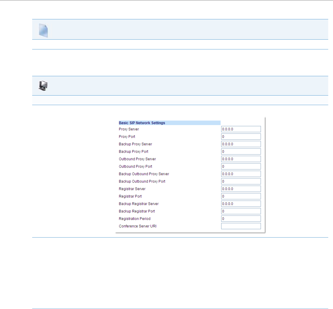
Operational Features
41-001343-02 REV04 – 05.2014 5-269
Configuring Centralized Conferencing Using the Aastra Web UI
Use the following procedure to configure centralized conferencing using the Aastra Web UI.
Configuration Files
For specific parameters you can set in the configuration files, see Appendix A, the section, “Centralized Conferencing Settings” on pageA-79.
Aastra Web UI
Global Configuration
1. Click on Advanced Settings->Global SIP Settings->Basic SIP Network Settings.
2. In the “Conference Server URI” field, do one of the following actions:
•To disable centralized conferencing on the IP phone, leave this field empty (blank).
•To enable SIP centralized conferencing on the IP phone, do one of the following actions:
–If you have specified a proxy server/registrar server, then to reach the media server via the proxy server, set this field to one of the fol-
lowing:
conf (Sylantro server), or
Conference (Broadsoft server)
By setting this field to conf or Conference, you specify conf@<proxy_server _address>: <proxy_port>. For example, if the proxy server
address is 206.229.26.60 and the port used is 10060, then by setting this parameter to conf, you are specifying the following:
conf@206.229.26.60:10060.
–To reach the media server using a different address/port than that specified by the proxy, set this field to the following:
conf@<media_server _address>: <media_port>
3. Click Save Settings to save your changes.
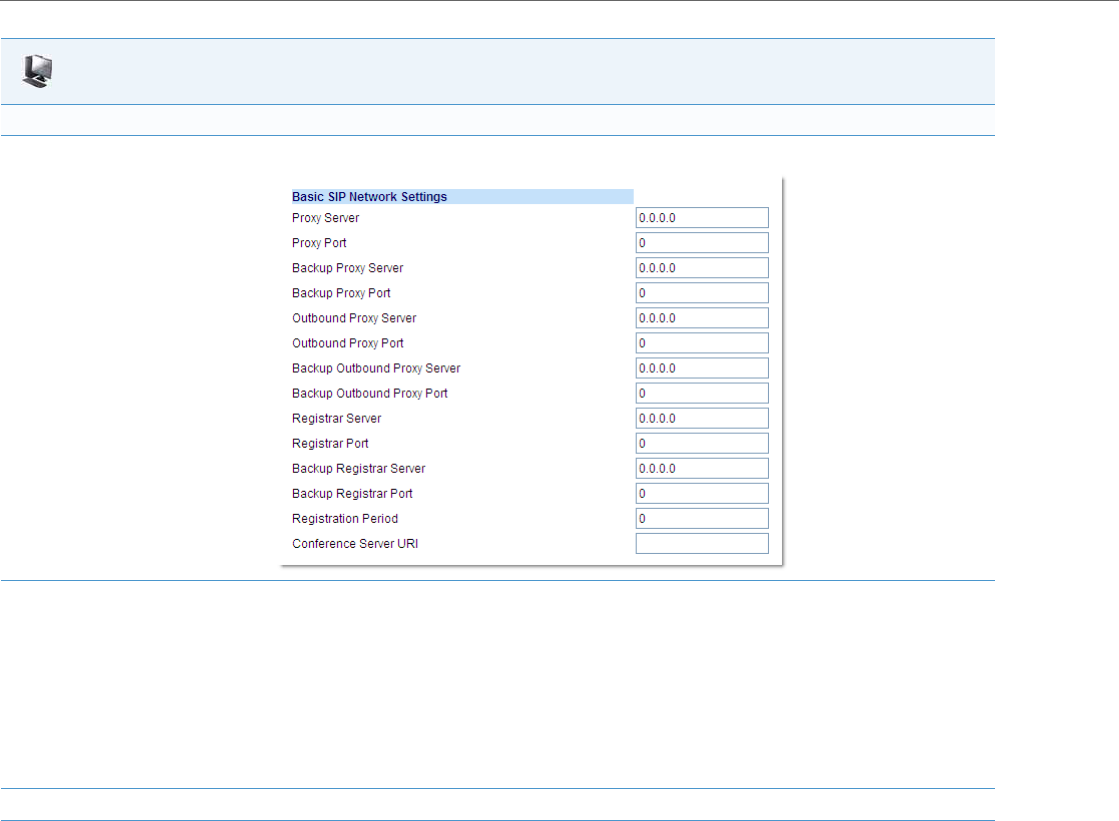
Operational Features
5-270 41-001343-02 REV04 – 05.2014
Per-Line Configuration
1. Click on Advanced Settings->Line <#>->Basic SIP Network Settings
2. In the “Conference Server URI” field, do one of the following actions:
•To disable centralized conferencing on this line, leave this field empty (blank).
•To enable SIP centralized conferencing on this line, do one of the following actions:
–If you have specified a proxy server/registrar server, then to reach the media server via the proxy server, set this field to one of the fol-
lowing:
conf (Sylantro server), or
Conference (Broadsoft server)
By setting this field to conf or Conference, you specify conf@<proxy_server _address>: <proxy_port>.
–To reach the media server using a different address/port than that specified by the proxy, set this field to the following:
conf@<media_server _address>: <media_port>
3. Click Save Settings to save your changes.
Aastra Web UI

Operational Features
41-001343-02 REV04 – 05.2014 5-271
Custom Ad-Hoc Conference
Previously, the phone will wait for server response prior to completing the ad-hoc and centralized conference feature. This
results in an interoperability issue with certain call managers, such as Genband. Now the phone no longer waits for server
response before referring the call to the conference host when the "custom adhoc conference" parameter is enabled.
Configuring the “Custom AD-Hoc Conference” Feature Using the Configuration Files
You use the following parameters to configure the “Custom AD- Hoc Conference” feature in the configuration files:
•custom adhoc conference
“SIP Join” Feature for 3-Way Conference
The IP Phones support a feature referenced in RFC 3911, which allows an additional caller to join an active call between
two parties if the caller knows the dialog information. This feature begins a conference using a join header as described in
RFC 3911.
The “SIP Join“ feature provides the following:
•Security via the whitelist (which is a feature that already exists on the phone).
•Initiates an offhook action uri when it is answered.
•Initiates an onhook action uri at call termination.
•Creates a caller list entry.
This feature is disabled by default. You can enable the “SIP Join” feature by setting the “sip join support” parameter in the
configuration files.
Limitations of the “SIP Join” Feature
The following are limitations of the “SIP Join” feature:
•Not applicable to a conference call already in progress.
•Not applicable to a CT handset that has two active calls.
•Not applicable to a phone mixing RTP.
•Allows secondary parties to join calls if they can determine the dialog parameters. In order to provide security, it is rec-
ommended that the Administrator configure the SIP whitelist.
•Not applicable while the active call between two parties is in the early dialog state.
Configuring the “SIP Join” Feature Using the Configuration Files
You use the following parameters to configure the “SIP Join feature in the configuration files:
sip join support
Configuration Files
For specific parameters you can set in the configuration files, see Appendix A, the section, “Custom Ad-Hoc Conference” on pageA-80.
Configuration Files
For specific parameters you can set in the configuration files, see Appendix A, the section, “SIP Join Feature for 3-Way Conference” on pageA-80.

Operational Features
5-272 41-001343-02 REV04 – 05.2014
Conference/Transfer Support for Live Dial Mode
By default, when users are initiating a conference call or transfer, they will not hear a dial tone before dialing begins (pre-
dial mode). The phone does not automatically dial out the number until the user presses the “Conf” or “Transfer” key.
This allows the users to make changes to the dialing number before initiating the call. Administrators can now enable
live dial mode by configuring the new “confxfer live dial” parameter. In live dial mode, when the user is completing a
conference call or transfer, they will hear a dial tone before dialing begins. In addition, the phone will either match the
number to the dial plan or wait for the set digit timeout.
In the default pre-dial mode, users are able to edit the destination number prior to dialing, whereas in live dial mode
they are not able to, however the “Dial” and “Cancel” softkeys are provided while the user inputs the number.
Reference
For more information about conference/transfer support for live dial mode, see your Aastra< Model-Specific> SIP IP
Phone User Guide.
Configuring Conference/Transfer in Live Dial Mode
You use the following parameters to configure conference/transfer feature in live dial mode:
•confxfer live dial
Authentication Support for HTTP/HTTPS Download Methods, used with
Broadsoft Client Management System (CMS)
The IP phones support HTTP/HTTPS digest authentication as defined in RFC 2617. (The HTTP client supports digest
authentication; the HTTP server does not; the HTTP server supports basic authentication). This feature allows the phones
to interoperate with Broadsoft’s CMS phone configuration tool.
Using the configuration files, you can enable/disable the following parameter to display a LOG IN softkey which allows
the HTTP/HTTPS server to perform digest authentication:
•http digest force login - specifies whether or not to display the LOG IN softkey on the IP Phone UI screen. Valid values
are 0 (disabled) or 1 (enabled). Default is 0 (disabled).
If the “http digest force login” parameter is set to 1 (enabled), after the phone boots, the LOG IN softkey displays on the
phone’s LCD. If the user presses this softkey, a username/password screen displays, allowing the user to enter the config-
ured username and password that is sent to the HTTP/HTTPS server for digest authentication by the server. By default,
username is “aastra” and password is “aastra”. You can enter the username and password in two ways:
•Using the configuration files, you can change the default values for the following parameters:
–http digest username - specifies the username to use for HTTP/HTTPS digest authentication.
–http digest password - specifies the password to use for HTTP/HTTPS digest authentication.
•By enabling the “http digest force login” parameter (setting to 1) - the phone displays the LOG IN key so the user can
enter the default username/password via the IP Phone UI.
Configuration Files
For specific parameters you can set in the configuration files, see Appendix A, the section, “Conference/Transfer in Live Dial Mode” on pageA-80.

Operational Features
41-001343-02 REV04 – 05.2014 5-273
Configuring Broadsoft CMS Support via the Configuration Files
Configure Broadsoft CMS support on the IP Phone using the following parameters in the configuration files:
•http digest force login
•http digest username
•http digest password
Using the IP Phone when Broadsoft CMS is Enabled
If you enable the HTTP/HTTPS digest authentication feature, the phone behaves as follows with the BroadSoft CMS tool:
Configuration Files
For specific parameters you can set in the configuration files, see Appendix A, the section, “HTTP/HTTPS Authentication Support for Broadsoft CMS”
on pageA-81.
1. Factory default the phone.
2. Configure the HTTP or HTTPS server (specify the HTTP or HTTPS server, path, and port).
3. Restart the phone.
The first time the phone reboots, the phone is challenged by the server. The phone sends the default username of
“aastra” and the default password of “aastra” to the server.
The server sends the default profile to the phone. This profile includes the information “http digest force login: 1”.
When the phone receives the profile, it displays the “Log In” key on the IP Phone UI’s idle screen.
4. Press the “Log In" key to displays the username/password screen
Note:
On the 8 and 11-Line LCD phones as well as the 6739i and 6867i, you use the Log In softkey to log in. On 3-Line LCD
phones, you press the right arrow key to log in.
5. Enter a username in the “Username” field (up to 40 characters) and a password in the “Password” field (up to 20
characters).
Note:
The “Username” and “Password” fields accept special characters, such as, @, #, %, =, _, etc. You can also specify
domain names in the Username field (i.e., user@domain).
6. After entering the username and password, press Submit.
The phone attempts to authenticate with the server. If successful, the phone reboots and loads the user configuration.
If unsuccessful, the phone displays “Authentication Failed”.
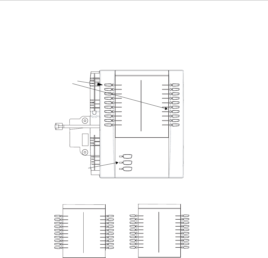
Operational Features
5-274 41-001343-02 REV04 – 05.2014
Customizing the Display Columns on the M675i Expansion Module
The M675i Expansion Module screen displays softkeys in column format. The function keys on the bottom left of the
Module allow you to display 3 full screens of softkeys. Each screen consists of 2 columns with the following default head-
ings on each page:
Page 1 "List 1" and "List 2"
Page 2 "List 3" and "List 4"
Page 3 "List 5" and "List 6"
To use the M675i, press the function key for the page you want to display to the LCD (page 1, page2, or page 3), and press
the applicable softkey.
You can customize the headings on each M675i Expansion Module screen using the configuration files. You use the fol-
lowing parameters to customize the column headings:
List 1 List 2
BLF 200
Home (speeddial)
Lock/Unlock
Softkeys
Function Keys
(Press for page 1)
(Press for page 2)
(Press for page 3)
Page 1 Screen
List 3 List 4 List 5 List 6
Page 2 Screen Page 3 Screen

Operational Features
41-001343-02 REV04 – 05.2014 5-275
Expansion Module 1 (3 pages)
•expmod1page1left
•expmod1page1right
•expmod1page2left
•expmod1page2right
•expmod1page3left
•expmod1page3right
Expansion Module 2 (3 pages)
•expmod2page1left
•expmod2page1right
•expmod2page2left
•expmod2page2right
•expmod2page3left
•expmod2page3right
Expansion Module 3 (3 pages)
•expmod3page1left
•expmod3page1right
•expmod3page2left
•expmod3page2right
•expmod3page3left
•expmod3page3right
The following is an example of configuring Expansion Module 1 column headings.
expmod1page1left: Personnel Ext
expmod1page1right: Operations Ext
expmod1page2left: Marketing Ext
expmod1page2right: Logistics Ext
expmod1page3left: Engineering Ext
expmod1page3right: Shipping Ext
Operational Features
5-276 41-001343-02 REV04 – 05.2014
These settings display to the Expansion Module as shown in the following illustrations.
Customizing the M675i Expansion Module Column Display
Configuration Files
For specific parameters you can set in the configuration files, see Appendix A, the section,“Customizing M675i Expansion Module Column Display” on
pageA-204.
Page 1 Screen
Personnel Ext Operations Ext
Marketing Ext Logistics Ext
Engineering Ext Shipping Ext
Page 2 Screen
Page 3 Screen

41-001343-02 REV04 – 05.2014 6-1
Chapter 6
Configuring Advanced Operational Features
About this Chapter
The IP phones have advanced operational features you can configure using the configuration files and/or the Aastra Web
UI. This chapter describes each of these features and provides procedures for configuring each feature.
Topics
This chapter covers the following topics:
Topic Page
Advanced Operational Features page6-3
TR-069 Support page6-4
MAC Address/Line Number in REGISTER Messages page6-5
SIP Message Sequence for Blind Transfer page6-7
SIP Message Sequence for Semi-Attended Transfer page6-7
Update Caller ID During a Call page6-8
Boot Sequence Recovery Mode page6-8
Auto-discovery Using mDNS page6-9
Single Call Restriction page6-9
Missed Call Summary Subscription page6-10
As-Feature-Event Subscription page6-11
Blacklist Duration page6-13
Whitelist Proxy page6-15
Transport Layer Security (TLS) page6-16
802.1x Support page6-20
Symmetric UDP Signaling page6-25
Symmetric TLS Signaling page6-25
Removing UserAgent and Server SIP Headers page6-26
GRUU and sip.instance Support page6-27
Multi-Stage Digit Collection (Billing Codes) Support (for Sylantro Servers) page6-27
Configurable DNS Queries page6-28
Ignore Out of Sequence Errors page6-29
“Early-Only” Parameter in Replaces Header RFC3891 page6-30
Switching Between Early Media and Local Ringing page6-30
Enable Microphone During Early Media page6-30
“Call-Info” Header to 200ok Responses for Shared Call Appearance (SCA) Lines page6-30
Reason Header Field in SIP Message page6-31

About this Chapter
6-2 41-001343-02 REV04 – 05.2014
Configurable “Allow” and “Allow-Event” Optional Headers page6-31
Configurable SIP P-Asserted Identity (PAI) page6-32
Configurable Route Header in SIP Packet page6-33
Configurable Compact SIP Header page6-33
Reject INV or BYE when Unsupported Value in REQUIRE Header page6-33
XML URI for Key Press Simulation page6-34
Domain Name System (DNS) Server Pre-caching Support page6-36
Configurable Transport Protocol for SIP Services and RTCP Summary Reports page6-40
Configurable Alphanumeric Input Order for Username Prompts page6-40
Active Voice-over-IP (VoIP) Recording page6-42
BroadSoft BroadWorks Executive and Assistant Services Feature page6-44
Topic Page

Advanced Operational Features
41-001343-02 REV04 – 05.2014 6-3
Advanced Operational Features
Description
This section provides the following information about advanced features of the IP phones:
Feature Description
TR-069 Support The IP Phones support the Technical Report (TR) 069 Protocol, a Protocol that provides the
communication between Customer-Premises Equipment (CPE) (like the IP Phones) and
Auto Configuration Servers (ACS) over DSL/broadband connections.
MAC Address/Line Number in REGISTER Messages Allows you to enable or disable the sending of the MAC address and line number from the
IP phone to the call server, in a REGISTER message.
SIP Message Sequence for Blind Transfer Allows you to enable or disable the phone to use the Blind Transfer method available in
software prior to release 1.4.
Update Caller ID During a Call Allows you to enable or disable the updating of the Caller ID information during a call.
Boot Sequence Recovery Mode Allows you to enable or disable Web recovery mode and set the maximum boot count on
the IP phone.
Auto-discovery Using mDNS The IP phones automatically perform an auto-discovery of all servers on a network using
mDNS. When the IP phone discovers a TFTP server, it is automatically configured by that
TFTP server.
Single Call Restriction Allows you to enable or disable a single call restriction between the 6757i CT base unit and
a call server.
Missed Call Summary Subscription Allows missed calls that have been redirected by the server, to be incremented in the
missed calls indicator on the phone it was initially directed to.
As-Feature-Event Subscription Allows you to enable or disable a specific line on the phone with the BroadSoft’s server-side
DND, CFWD, or ACD features.
Blacklist Duration Allows you to specifies the length of time, in seconds, that a failed server remains on the
server blacklist. The IP phone avoids sending a SIP message to a failed server (if another
server is available) for this amount of time.
Whitelist Proxy Allows you to configure the phone to either accept or reject call requests from a trusted
proxy server.
Transport Layer Security (TLS) Allows you to enable or disable the use of Persistent Transport Layer Security (TLS).
Persistent TLS sets up the connection to the server once and re-uses that connection for all
calls from the phone. The setup connection for Persistent TLS is established during the reg-
istration of the phone. If the phones are set to use Persistent TLS, and a call is made from the
phone, this call and all subsequent calls use the same authenticated connection. This sig-
nificantly reduces the delay time when placing a call.
802.1x Support Allows you to enable or disable the 802.1x Protocol support on the IP Phones.
Symmetric UDP Signaling Allows you to enable or disable the phone to use port 5060 to send SIP UDP messages.
Symmetric TLS Signaling Allows you to enable or disable the phone to use port 5061 to send SIP TLS messages.
Removing UserAgent and Server SIP Headers Allows you to enable or disable the addition of the User-Agent and Server SIP headers in
the SIP stack.
GRUU and sip.instance Support The IP phones provide GRUU support using draft-ietf-sip-gruu-15. A sip.instance is added
to all non-GRUU contacts.
Multi-Stage Digit Collection (Billing Codes) Support (for
Sylantro Servers) IP Phones support Sylantro Server features, like mandatory and optional billing codes that
require the application server to notify the phone to collect more digits before completing
the call. The IP phone is able to collect digits in two stages to support the billing code fea-
ture.
Configurable DNS Queries Allows you to specify the Domain Name Service (DNS) query method to use when the
phone performs a DNS lookup.
Ignore Out of Sequence Errors Allows you to configure the phone to ignore CSeq number errors on all SIP dialogs on the
phone.

Advanced Operational Features
6-4 41-001343-02 REV04 – 05.2014
TR-069 Support
The IP Phones support the Technical Report (TR)-069 Protocol. This Protocol is a bi-directional HTTP based protocol that
provides the communication between Customer-Premises Equipment (CPE) (like the IP Phones) and Auto Configuration
Servers (ACS) over DSL/broadband connections. It includes both a safe auto configuration and the control of other CPE
management functions within an integrated framework.
Service providers can, through TR-069, use one common platform to manage (through the internet) all of their customer
premise devices, regardless of the device or manufacturer. If TR-069 is enabled on the phones, when the remote ACS
boots the phones, they contact the ACS and establish the configuration automatically.
“Early-Only” Parameter in Replaces Header RFC3891 The phones support the “early-only” parameter in the “Replaces” header as referenced in
RFC3891.
Switching Between Early Media and Local Ringing The phones support switching between early media and local ring tone.
Enable Microphone During Early Media Allows you to enable or disable the microphone during early media.
“Call-Info” Header to 200ok Responses for Shared Call
Appearance (SCA) Lines In Release 2.6 and up, a “Call-Info” header is included in the 200ok response to an INVITE,
RE-INVITE, and UPDATE messages for SCA lines.
Reason Header Field in SIP Message The IP Phones support the receiving of the Reason Header Field in a SIP CANCEL message,
as described in RFC3326.
Configurable “Allow” and “Allow-Event” Optional Head-
ers On the IP Phones, an Administrator can enable or disable whether or not the optional
“Allow” and “Allow-Events” headers are included in the NOTIFY message from the phone.
Configurable SIP P-Asserted Identity (PAI) The IP Phones support a private extension to SIP for Asserted Identity within trusted net-
works (as defined in RFC 3325).
Configurable Route Header in SIP Packet The IP Phones support a parameter that enables or disables the addition of the Route
header in a SIP packet.
Configurable Compact SIP Header The phones provide a feature that allows an Administrator to shorten the length of a SIP
packet by using the compact form. This feature is in accordance with Compact SIP Headers
defined in RFC 3261.
Reject INV or BYE when Unsupported Value in REQUIRE
Header The IP Phones support a parameter that allows you to enable or disable the rejection of an
INV or BYE with a “420 Bad Extension” if the INV or BYE contains an unsupported value in
the REQUIRE header.
XML URI for Key Press Simulation The phones provide a feature that allow an XML Developer or Administrator to define XML
Key URIs that can send key press events to the phone, just as if the physical hard key,
softkey, or programmable key were pressed on the phone.
Domain Name System (DNS) Server Pre-caching Support This feature allows administrators to configure the phone to download a text file which
contains persistent DNS “A record” hostname to IP address mappings. In addition, support
for persistent DNS “SRV records” has been added to permit SRV based high availability of
services.
Configurable Transport Protocol for SIP Services and
RTCP Summary Reports The IP Phones support a parameter that allows administrators to ability to configure the
transport protocols used for SIP services and RTCP summary reports.
Configurable Alphanumeric Input Order for Username
Prompts This feature allow administrators the ability to change the default behavior of the keypad
input order during username prompts from uppercase letters > digit > lower case letters to
digit > uppercase letters > lower case letters.
Active Voice-over-IP (VoIP) Recording When using the IP phones with an Aastra call manager supporting voice recording and a
recording system with the predefined subset of the SIP interface, administrators can con-
figure the phones to send duplicate copies of the transmit and receive RTP or SRTP voice
packets to the voice recording system.
BroadSoft BroadWorks Executive and Assistant Services
Feature The Executive and Assistant Services feature allows Administrators to create an inter-net-
work relationship between Executives and Assistants allowing calls to the Executive’s
phone to be screened, filtered, and routed to an Assistant, whereby the Assistant can
answer, divert, or push the filtered call back to the Executive (6730i, 6731i, 6753i, 6755i,
6757i, 6757i CT, 9143i, 9840i, and 9840i CT IP phones only).
Feature Description

Advanced Operational Features
41-001343-02 REV04 – 05.2014 6-5
In addition to configuring the phone with TR-069, you can also do the following:
•Reboot the phone
•Reset to factory defaults
•Update the firmware of the device
•Backup/restore configuration
•Upload the log file
Reference
For more information about TR-069, see the Aastra TR-069 Configuration Guide.
MAC Address/Line Number in REGISTER Messages
The IP phones can send the MAC address and line number in the REGISTER packets making it easier for the call server
when a user configures the phones via the Aastra Web UI or the IP Phone UI. The following two configurable headers send
this information to the call server:
Aastra-Mac: <mac address>
Aastra-Line: <line number>
The MAC address is sent in uppercase hex numbers, for example, 00085D03C792. The line number is a number between 1
and 9.
The following parameters allow you to enable/disable the sending of MAC address and line number to the call server:
•sip send mac
•sip send line
These parameters are disabled by default. The parameters are configurable via the configuration files or the Aastra Web UI.
Configuring the MAC address/Line Number in REGISTER Message
Configuration Files
For specific parameters you can set in the configuration files for enabling/disabling MAC address and line number, see Appendix A, the section,
Advanced Operational Parameters on pageA-205.
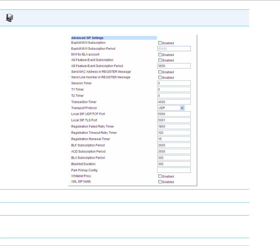
Advanced Operational Features
6-6 41-001343-02 REV04 – 05.2014
Aastra Web UI
1. Click on Advanced Settings->Global SIP->Advanced SIP Setting.
2. Enable the "Send MAC Address in REGISTER Message" field by checking the check box.
(Disable this field by unchecking the box).
3. Enable the "Send Line Number in REGISTER Message" field by checking the check box.
(Disable this field by unchecking the box).
4. Click Save Settings to save your settings.
Note:
The session prompts you to restart the IP phone to apply the configuration settings.
5. Select Operation->Reset and click Restart.

Advanced Operational Features
41-001343-02 REV04 – 05.2014 6-7
SIP Message Sequence for Blind Transfer
The SIP message sequence for Blind Transfer avoids the transfer target having two simultaneous calls. Prior to release 1.4,
a CANCEL message was sent to the transfer target (if it was in a ringing state) after sending a REFER to the transferee to
complete the transfer. In the 1.4 and later releases, the CANCEL is now sent before the REFER message.
The following parameter allows the system administrator to force the phone to use the Blind Transfer method available in
software versions prior to 1.4:
•sip cancel after blind transfer
This parameter is configurable via the configuration files only.
Configuring SIP Message Sequence for Blind Transfer
SIP Message Sequence for Semi-Attended Transfer
The SIP message sequence for a Semi-Attended Transfer allows the transferor to start the transfer while the target phone is
still ringing.
The following parameter supports different behaviors of a semi-attended transfer:
•sip refer-to with replaces
This parameter is configurable via the configuration files only.
The combination of this new parameter (“sip refer-to with replaces”) and the existing parameter (“sip cancel after blind
transfer”) determines how the semi-attended transfer is completed. The following table shows how the old and new
parameters work together:
On the transferor phone, the REFER request will always be sent to the transferee.
Configuring SIP Message Sequence for Semi-Attended Transfer
Configuration Files
For the specific parameter you can set in the configuration files for enabling/disabling the blind transfer method, see Appendix A, the section, “Blind
Transfer Setting” on pageA-205.
IF THEN
The “sip cancel after blind transfer” parameter is set to 0 and the “sip refer-
to with replaces” parameter is set to 0 The phone sends CANCEL before REFER for semi-attended transfer.
The “sip cancel after blind transfer” parameter is set to 1 and the “sip refer-
to with replaces” parameter is set to 0 The phone sends CANCEL after REFER for semi-attended transfer.
The “sip cancel after blind transfer” parameter is set to 0 and the “sip refer-
to with replaces” parameter is set to 1 The phone sends REFER with Replaces for semi-attended transfer and NO
CANCEL.
The “sip cancel after blind transfer” parameter is set to 1 and the “sip refer-
to with replaces” parameter is set to 1 The phone sends REFER with Replaces for semi-attended transfer and NO
CANCEL.
Configuration Files
For the specific parameter you can set in the configuration files for customizing the semi-attended transfer method, see Appendix A, the section,
““Semi-Attended Transfer Settings”” on pageA-205.

Advanced Operational Features
6-8 41-001343-02 REV04 – 05.2014
Update Caller ID During a Call
It is possible for a proxy or call server to update the Caller ID information that displays on the phone during a call, by
modifying the SIP Contact header in the re-INVITE message. The phone displays the updated name and number informa-
tion contained within the Contact header.
The following parameter allows the system administrator to enable or disable this feature:
•sip update callerid
This parameter is configurable via the configuration files only.
Configuring Update Caller ID During a Call
Boot Sequence Recovery Mode
You can force the IP phone into recovery mode by pressing the 1 and # keys during boot up when the logo displays. This
feature is enabled by default on the IP phone.
You can disable this feature using the following parameter in the configuration files:
•force web recovery mode disabled
Valid values for this parameter are 0 (false) and 1 (true). Default is 0 (false).
A boot counter increments after each faulty boot. When the counter reaches a predetermined value, it forces Web recov-
ery mode. The counter is reset to zero upon a successful boot.
The predetermined value is set using the following parameter in the configuration files:
•max boot count
A zero (0) value disables this feature. The default value is 10.
You can configure the boot sequence recovery mode parameters using the configuration files only.
Configuring Boot Sequence Recovery Mode
Configuration Files
For the specific parameter you can set in the configuration files for enabling/disabling the update of caller ID during a call, see Appendix A, the section,
“Update Caller ID Setting” on pageA-205.
Note:
After the phone has been successfully recovered through the web recovery mode, the phone will fully download and
upgrade to the firmware defined in the configuration files (upon reboot) or pushed through the Web UI even if the
defined/pushed firmware’s version is identical to the version already loaded on the phone.
Configuration Files
For the specific parameters you can set in the configuration files for boot sequence recovery mode, see Appendix A, the section, “Boot Sequence
Recovery Mode Settings” on pageA-206.

Advanced Operational Features
41-001343-02 REV04 – 05.2014 6-9
Auto-discovery Using mDNS
The IP phones can perform an auto-discovery of all servers on a network using mDNS. When the IP phone discovers a TFTP
server, it is automatically configured by that TFTP server.
An unconfigured phone (phone right out of the box) added to a network, attempts to auto-discover a configuration server
on the network without any end-user intervention. When it receives DHCP option 66 (TFTP server), it automatically gets
configured by the TFTP server.
An already configured phone (either previously configured by auto-discovery or manually configured) added to a net-
work, uses its predefined configuration to boot up.
Single Call Restriction
On the 6757i CT and 9480i CT, an administrator can enable or disable a single call restriction between the 6757i CT and
9480i CT base unit and a call server.
When this feature is enabled (set to 1), you can make separate active calls from the 6757i CT and 9480i CT base unit and
from the cordless handset. If this feature is disabled (set to 0), only one call can be active at a time either from the base unit
or from the handset. When this feature is disabled, and you make an active call on either the base unit or the handset, any
other attempt to make an active call is put on hold. Also, when this feature is disabled, more than one call can negotiate
complex audio codecs since only a single call is decoding audio at a time.
You can configure this feature via the configuration files or the Aastra Web UI.
Notes:
•Configuration parameters received via DHCP do not constitute configuration information, with the exception of a
TFTP server. Therefore, you can plug a phone into a DHCP environment, still use the auto-discovery process, and still
allow the use of the TFTP server parameter to set the configuration server.
•DHCP option 66 (TFTP server details) overrides the mDNS phase of the auto-discovery. Therefore, the DHCP option
takes priority and the remaining process of auto-discovery continues.
•As the phone performs auto-discovery, all servers in the network (including the TFTP server), display in the phone
window. However, only the server configured for TFTP automatically configures the phone.
Note:
Applicable to the 6757i CT and 9480i CT IP Phones only.
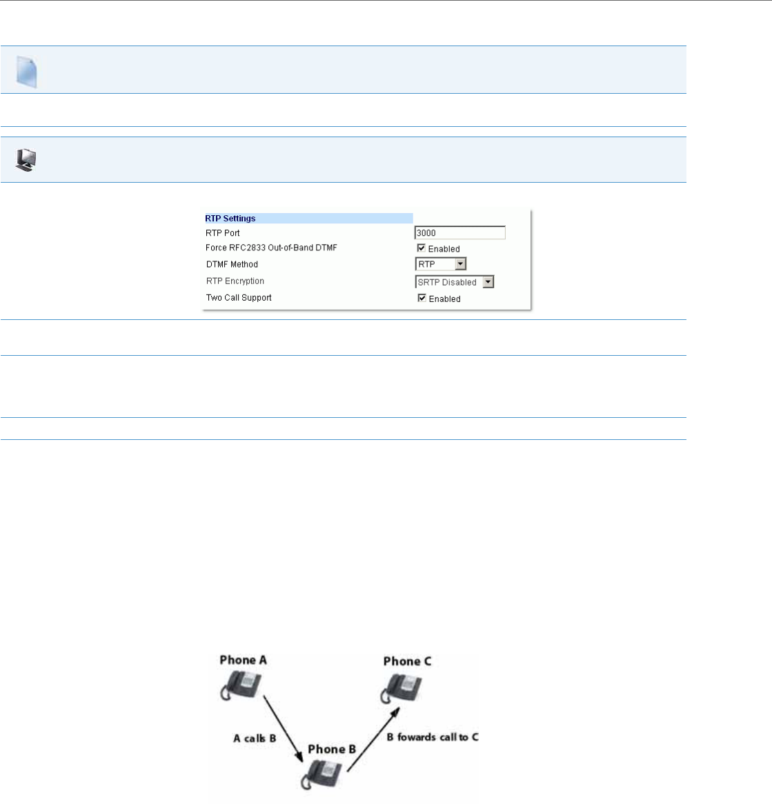
Advanced Operational Features
6-10 41-001343-02 REV04 – 05.2014
Configuring Single Call Restriction
Missed Call Summary Subscription
The “Missed Call Summary Subscription” feature allows missed calls that have been redirected by the server, to be
incremented in the missed calls indicator on the phone it was initially directed to. This feature is called the Missed Call
Summary Subscription and can be set with a timer that allows the phone to use the feature for a period of time before
the timer expires. For this feature to work, you must configure voicemail on the phone that the call was initially directed
to.
For example, phones A, B, and C are connected to the server. You configure the server to direct calls coming into phone B
(which has voicemail configured) to be forwarded to phone C. When phone A calls phone B, the server forwards the call
to phone C. With this feature, phone B receives notification from the server that the call was forwarded and the missed
calls indicator is incremented on phone B.
An Administrator can configure this feature on a global or per-line basis using the configuration files.
Configuration Files
For the specific parameters you can set in the configuration files for single call restriction on the 6757i CT and 9480i CT, see Appendix A, the section,
“Single Call Restriction Setting” on pageA-206.
Aastra Web UI
1. Click on Advanced Settings->Global SIP->RTP Settings.
2. Enable the "Two Call Support" field by checking the check box.
(Disable this field by unchecking the box).
3. Click Save Settings to save your settings.
Note:
The session prompts you to restart the IP phone to apply the configuration settings.
4. Select Operation->Reset and click Restart.
Missed calls indicator increments on phone B.
Note: Voicemail must be configured on phone B

Advanced Operational Features
41-001343-02 REV04 – 05.2014 6-11
Configuring Missed Call Summary Subscription using the Configuration Files
In addition to enabling/disabling the Missed Call Summary Subscription, You can also configure the amount of time, in
seconds, that the phone uses this feature. The timer is configurable on a global basis only.
You use the following parameters to configure Missed Call Summary Subscription feature on a global basis:
Global Parameters
•sip missed call summary subscription
•sip missed call summary subscription period
Use the following parameters to configure Missed Call Summary Subscription feature on a per-line basis:
Per-Line Parameter
•sip lineN missed call summary subscription
As-Feature-Event Subscription
The IP phones support server-side Do Not Disturb (DND), Call Forward (CFWD), and Automatic Call Distribution (ACD) fea-
ture events. This feature is called “as-feature-event” and works with the DND, CFWD, and ACD keys.
This feature is configurable using the configuration files or the Aastra Web UI.
How it Works on the Phone UI
When you enable the “as-feature-event” on the phone, AND you activate a DND, CFWD, and/or ACD key, pressing the key
performs as follows:
•If the key is configured for an account on the phone, the server applies DND, CFWD or ACD to that account. (For infor-
mation about CFWD and DND account configuration, see Chapter 3, the section, “Account Configuration” on page3-
27).
•If the key is “custom” configured, a screen displays on the phone allowing the user to choose the account to apply DND
or CFWD. (For information about CFWD and DND custom configuration, see Chapter 3, the section, “Account Configura-
tion” on page3-27).
•A solid “Message Waiting Indicator” (MWI) indicates if one line/account has DND or CFWD enabled, and the LED next to
the DND/CFWD key is ON. A status displays on the LCD that indicates the status of the line in focus (for example, the sta-
tus of CFWD could be “Call Forward Busy” (CFWDB) or “Call Forward No Answer” (CFWDNA).
When you press the DND, CFWD, or ACD key, only one attempt is made to enable/disable the “as-feature-event” feature on
the server. The message “Trying” displays on the phone’s LCD after pressing the key. If the attempt is successful, the idle
screen displays. If the attempt is unsuccessful, the message “Failed” displays. The user can press the softkey again to re-
attempt the feature if required.
Configuration Files
For the specific parameters you can set in the configuration files for Missed Call Summary Subscription, see Appendix A, the section, “Missed Call Sum-
mary Subscription Settings” on pageA-87.
Note:
The DND, CFWD, and ACD server-side feature is not applicable to the CT handset.
Note:
If the ACD key is configured on the phone, and the “as-feature-event” is not enabled, the phones uses the ACD icons
and LED behavior from a Sylantro server instead.
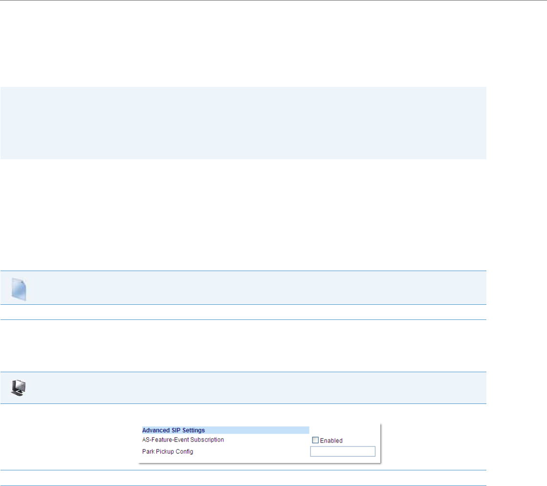
Advanced Operational Features
6-12 41-001343-02 REV04 – 05.2014
For server-side ACD, when you press the ACD softkey, the screen that displays is dependant on the state of the ACD sub-
scription. Possible state for ACD are:
•Logged Out - User has the option of logging in.
•Logged In - User has the option of logging out or making the phone unavailable.
•Unavailable - User has the option of logging out or making the phone available.
Configuring As-Feature-Event Subscription Using the Configuration Files
If the phone-side features of the DND, CFWD, and ACD keys are enabled, the phone uses the existing parameter values
for these keys. If the server-side features are enabled, the phone saves the state of the features from the server on the
phone.
Use the following parameters to enable/disable the server-side “as-feature-event” on the IP Phone:
•sip lineN as-feature-event subscription
•sip as-feature-event subscription period
Configuring As-Feature-Event Subscription Using the Aastra Web UI
Use the following procedure to enable/disable the server-side “as-feature-event” on the IP Phone using the Aastra Web
UI.
Notes:
•If DND and CFWD are configured to use “Account” mode on the IP Phone, pressing the DND and CFWD keys apply to
the account in focus as described in Chapter 3, the section, “Account Configuration” on page3-27.
•If ACD is configured on the phone, the ACD softkey applies to the line for which the key is configured. The ACD
softkey must be configured for the first line of an account. For example, if account 2 has line 3 and line 4 you must
configure the ACD softkey for line 3.
Configuration Files
For the specific parameters you can set in the configuration files, see Appendix A, the section, “As-Feature-Event Subscription Settings” on pageA-88.
Aastra Web UI
1. Click on Advanced Settings->LineN->Advanced SIP Settings.
2. Enable the "As-Feature-Event Subscription" field, by checking the check box. (Disable this field by unchecking the box).
3. Click Save Settings to save your changes.
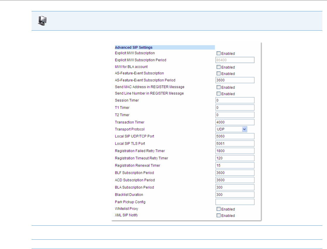
Advanced Operational Features
41-001343-02 REV04 – 05.2014 6-13
Blacklist Duration
The Blacklist Duration feature helps to reduce unnecessary delays during proxy/registrar server failures, caused by the IP
phone repeatedly sending SIP messages to a failed server. If you enable this feature, then whenever the IP phone sends a
SIP message to a server, and does not get a response, the phone automatically adds the server to the blacklist. The IP
phone avoids sending messages to any servers on the blacklist. If all servers are on the blacklist, then the IP phone
attempts to send the message to the first server on the list.
You can specify how long failed servers remain on the blacklist in the IP phone’s configuration file or in the Aastra Web UI.
The default setting is 300 seconds (5 minutes). If you set the duration to 0 seconds, then you disable the blacklist feature.
4. Click on Advanced Settings->Global SIP->Advanced SIP Settings.
5. In the “As-Feature-Event Subscription Period” field, enter the amount of time, in seconds, that the phone waits after sending a SUBSCRIBE,
to receive a NOTIFY response from the server side. Default is 3600.
6. Click Save Settings to save your changes.
Aastra Web UI
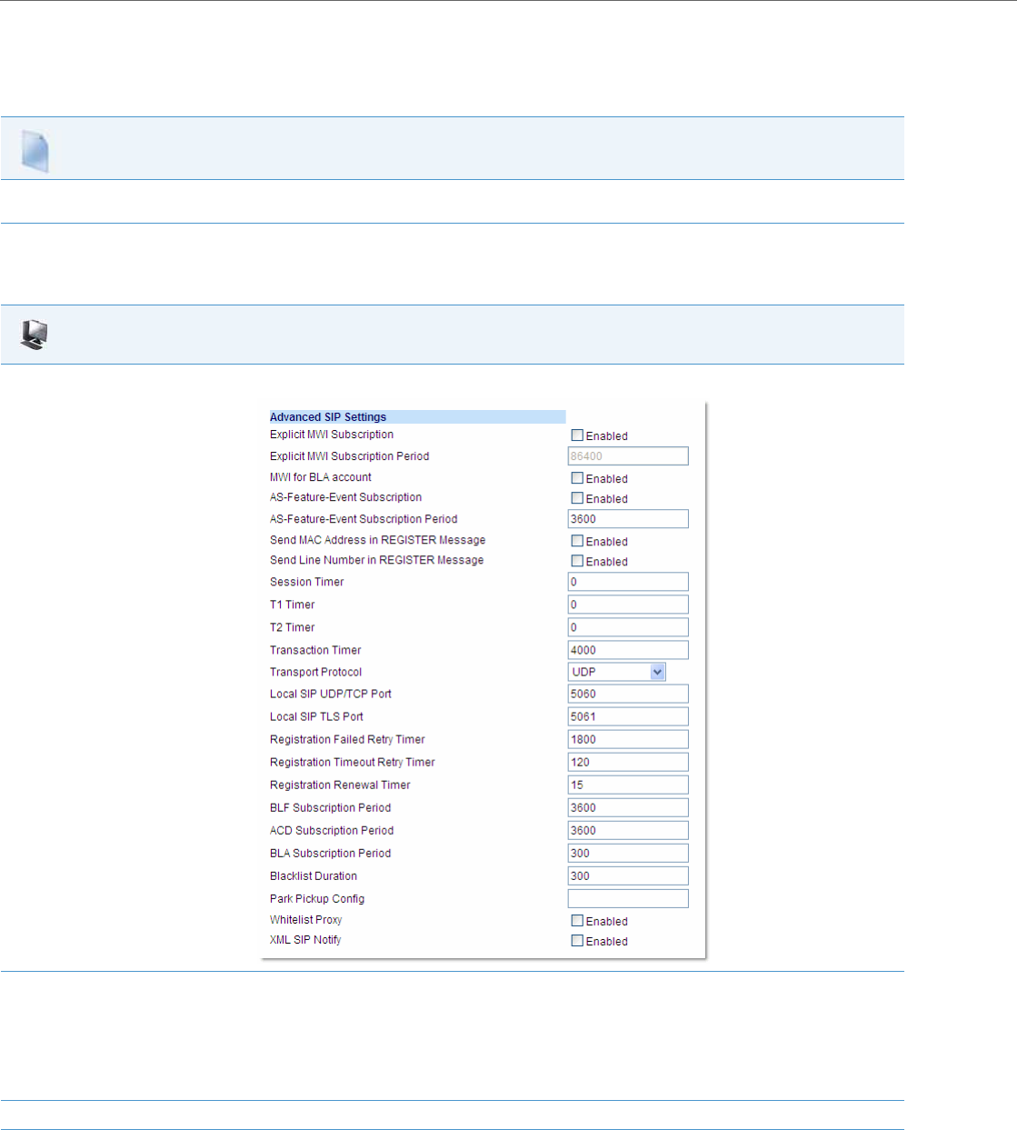
Advanced Operational Features
6-14 41-001343-02 REV04 – 05.2014
Configuring Blacklist Duration Using the Configuration Files
Use the following parameter to configure the Blacklist Duration in the configuration files:
•sip blacklist duration
Configuring a Server Blacklist Using the Aastra Web UI
You use the following procedure to configure Blacklist Duration using the Aastra Web UI.
Configuration Files
For the specific parameters you can set in the configuration files for setting Blacklist Duration, see Appendix A, the section, “Blacklist Duration Setting”
on pageA-207.
Aastra Web UI
1. Click on Advanced Settings->Global SIP->Advanced SIP Settings
2. In the “Blacklist Duration” field, specify the length of time, in seconds, that a failed server remains on the server blacklist. The IP phone
avoids sending a SIP message to a failed server (if another server is available) for this amount of time. Valid values are 0 to 9999999. Default
is 300 seconds (5 minutes).
For example: 600
Note:
The value of “0” disables the blacklist feature.
3. Click Save Settings to save your changes.

Advanced Operational Features
41-001343-02 REV04 – 05.2014 6-15
Whitelist Proxy
To protect your IP phone network, you can configure a “Whitelist Proxy” feature that screens incoming call requests
received by the IP phones. When this feature is enabled, an IP phone accepts call requests from a trusted proxy server only.
The IP phone rejects any call requests from an untrusted proxy server.
The whitelist is dynamically updated (i.e. the phones are able to refresh and resync the whitelist [without a reboot] if the IP
addresses corresponding to the proxy FQDNs are changed on the DNS server).
The IP phone monitors the following events and an update is triggered if required:
•200 OK responses to REGISTER requests if the peer’s IP address is not currently in the whitelist.
•200 OK responses to INVITE requests if the peer’s IP address is not currently in the whitelist.
•INVITE requests from untrusted proxy servers.
Configuring Whitelist Proxy Using the Configuration Files
You use the following parameter to configure the whitelist proxy feature using the configuration files:
•sip whitelist
Note:
An update will not be triggered for the following events:
•200 OK responses to INVITE requests for an IP call.
•When more than one INVITE requests are received from the same untrusted proxy server.
Configuration Files
For the specific parameters you can set in the configuration files for setting Whitelist Proxy, see Appendix A, the section, “Whitelist Proxy Setting” on
pageA-207.
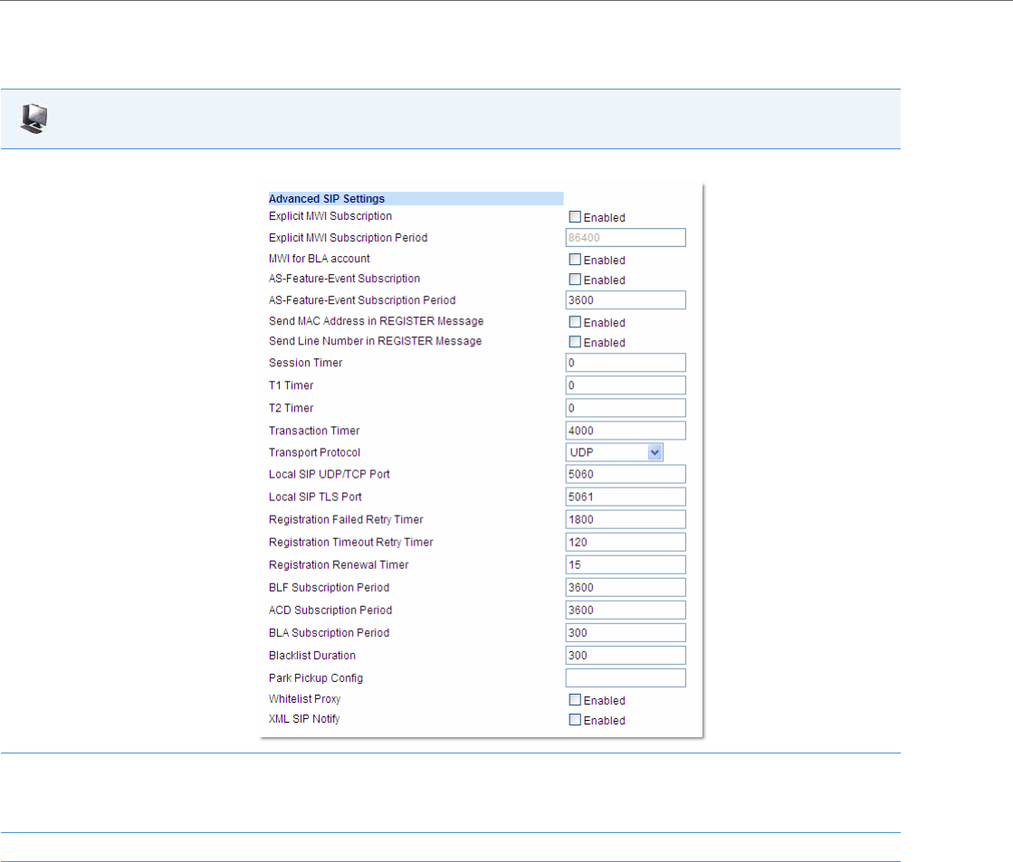
Advanced Operational Features
6-16 41-001343-02 REV04 – 05.2014
Configuring Whitelist Proxy Using the Aastra Web UI
Use the following procedure to configure the Whitelist Proxy feature using the Aastra Web UI.
Transport Layer Security (TLS)
The IP Phones support a transport protocol called Transport Layer Security (TLS) and Persistent TLS. TLS is a protocol
that ensures communication privacy between the SIP phones and the Internet. TLS ensures that no third party may
eavesdrop or tamper with any message.
Aastra Web UI
1. Click on Advanced Settings->Global SIP->Advanced SIP Settings
2. The "Whitelist Proxy" field is disabled by default. To enable this field, check the box.
When this feature is enabled, an IP phone accepts call requests from a trusted proxy server only. The IP phone rejects any call requests from
an untrusted proxy server.
3. Click Save Settings to save your changes.

Advanced Operational Features
41-001343-02 REV04 – 05.2014 6-17
TLS is composed of two layers: the TLS Record Protocol and the TLS handshake protocol. The TLS Record Protocol provides
connection security with some encryption method such as the Data Encryption Standard (DES). The TLS Handshake Proto-
col allows the server and client to authenticate each other and to negotiate an encryption algorithm and cryptographic
keys before data is exchanged. TLS requires the use of the following security certificate files to perform TLS handshake:
•Root and Intermediate Certificates
•Local Certificate
•Private Key
•Trusted Certificate
When the phones use TLS to authenticate with the server, each individual call must setup a new TLS connection. This can
take more time when placing each call. Thus, the IP phones also have a feature that allows you to setup the connection to
the server once and re-use that one connection for all calls from the phone. It is called Persistent TLS. The setup connec-
tion for Persistent TLS is established during the registration of the phone. If the phones are set to use Persistent TLS, and a
call is made from the phone, this call and all subsequent calls use the same authenticated connection. This significantly
reduces the delay time when placing a call.
On the IP phones, an Administrator can configure TLS and Persistent TLS on a global-basis only, using the configuration
files or the Aastra Web UI.
There is a keep-alive feature for persistent TLS connections only. Administrators can configure this keep-alive feature using
the parameter called “sip persistent tls keep alive”. When this feature is configured, the phone will send keep-alive pings
to the proxy server at configured intervals. The keep-alive feature for persistent TLS connections performs the following
functionalities:
•After a persistent TLS connection is established or re-established, activate the keep-alive, which will send CRLF to peer
periodically.
•The phone will retry the connection automatically when a persistent TLS connection is down.
•When a persistent TLS connection is re-established (primary is up or primary is down and backup is up), refresh registra-
tion of the accounts associated with the connection.
•When a persistent TLS connection to primary is down, switch to backup if connection to backup is working.
Additionally the “sip send sips over tls” parameter allows administrators the ability to manually configure the IP phones
to use either the SIP or SIPS URI scheme when TLS or persistent TLS is enabled. Disabling the “sip send sips over tls”
parameter (i.e. defining the parameter as “0” in the configuration files) ensures the IP phones use the SIP URI scheme when
TLS or persistent TLS is enabled. Enabling the parameter (i.e. defining the parameter as “1”) ensures the phones use the
SIPS URI scheme in such scenarios. The SIPS URI scheme is used by default.
Notes:
•There can be only one persistent TLS connection created per phone.
•If you configure the phone to use Persistent TLS, you must also specify the Trusted Certificate file to use. The Root and
Intermediate Certificates, Local Certificate, and Private Key files are optional.

Advanced Operational Features
6-18 41-001343-02 REV04 – 05.2014
Configuring TLS Using the Configuration Files
You use the following parameters to configure TLS in the configuration files:
•sip transport protocol
•sips persistent tls
•sip persistent tls keep alive
•sip send sips over tls
•sips root and intermediate certificates
•sips local certificate
•sips private key
•sips trusted certificates
Configuration Files
For the specific parameters you can set in the configuration files for setting TLS, see Appendix A, the section, “Transport Layer Security (TLS) Settings”
on pageA-89.
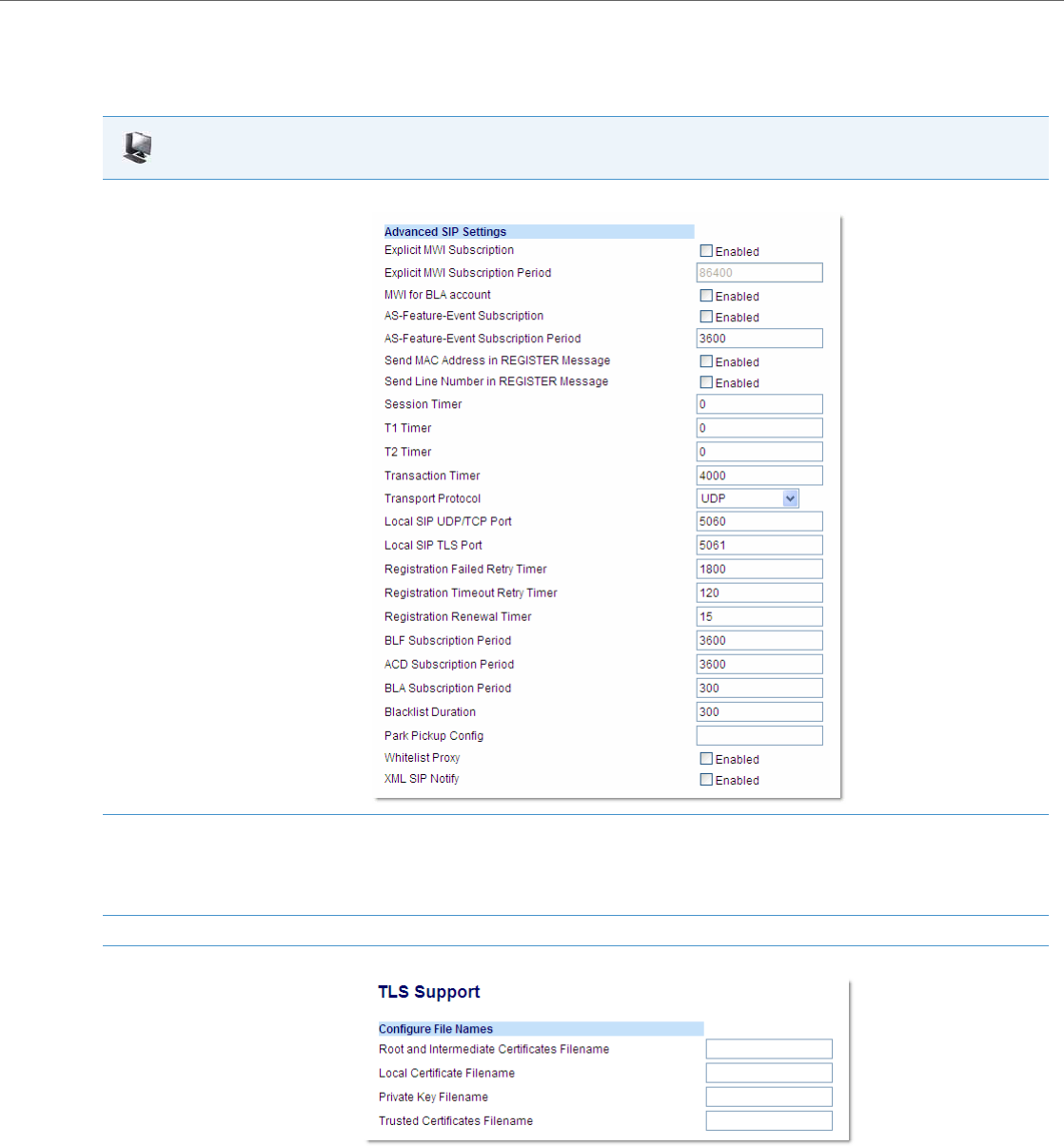
Advanced Operational Features
41-001343-02 REV04 – 05.2014 6-19
Configuring TLS Using the Aastra Web UI
To configure TLS using the Aastra Web UI, you must enable TLS or Persistent TLS first. Then you must define the TLS certif-
icate file names that you want the phone to use. Use the following procedure to configure TLS using the Aastra Web UI.
Aastra Web UI
1. Click on Advanced Settings->Global SIP->Advanced SIP Settings.
2. In the "Transport Protocol" field, select TLS or Persistent TLS.
Note:
If configuring Persistent TLS, you must go to Advanced Settings->Global SIP->Basic Network Settings and configure the “Outbound Proxy
Server” and “Outbound Proxy Port” parameters.
3. Click Save Settings to save your changes.
4. Click on Advanced Settings->TLS Support.

Advanced Operational Features
6-20 41-001343-02 REV04 – 05.2014
802.1x Support
The IP phones support the IEEE 802.1x protocol. The 802.1x protocol is a standard for passing Extensible Authentication
Protocol (EAP) over a wired or wireless Local Area Network (LAN).
The 802.1x protocol on the IP phone facilitates media-level access control, and offers the capability to permit or deny
network connectivity, control LAN access, and apply traffic policy, based on user or endpoint identity. This feature sup-
ports both the EAP-MD5 and EAP-TLS protocols.
If 802.1x on the phone is enabled, a “802.1x Authenticating...” message displays during startup of the phone.
If the 802.1x failed to authenticate with the server, the phone continues its normal startup process using DHCP. However,
the network port on the phone may or may not be disabled, depending on the switch configuration.
Certificates and Private Key Information
•If the certificates and private key are NOT stored in the phone:
–the phone connects to an open unauthenticated VLAN and the certificates are downloaded.
or
–the phone connects using EAP-MD5 to a restricted VLAN and the certificates are downloaded.
•If the certificates and private key ARE stored in the phone, the phone uses them during the authentication process.
•If the phone uses EAP-TLS for successful authentication, after the phone reboots, it downloads the latest certificates
and private key files to the phone.
•The private key uses AES-128 to encrypt the private key file.
•Switch Supplicant Mode - The switch supports the following 2 modes:
–Single supplicant - This mode enables the port once any machine connected to this port is authenticated. For
security reasons, the IP phone has the option to disable the pass-through port.
–Multiple supplicants - Using this mode, the switch can support multiple clients connected to same port. The
switch distinguishes between the clients based on their MAC address.
•Factory default and recovery mode deletes all certificates and private keys, and sets the EAP type to disabled.
You can configure the 802.1x feature on the IP phone using the configuration files, the IP Phone UI, or the Aastra Web UI.
5. Enter the certificate file names and the private key file name in the appropriate fields.
The Root and Intermediate Certificate files contain one root certificate and zero or more intermediate certificates which must be placed in
order of certificate signing with root certificate being the first in the file. If the local certificate is signed by some well known certificate
authority, then that authority provides the user with the Root and Intermediate Certificate files (most likely just CA root certificate).
The Trusted Certificate files define a list of trusted certificates. The phone’s trusted list must contain the CA root certificates for all the servers
it is connecting to. For example, if the phone is connecting to server A which has a certificate signed by CA1, and server B, which has a cer-
tificate signed by CA2, the phone must have CA1 root certificate and CS2 root certificate in its Trusted Certificate file.
Notes:
•If configuring TLS, you must specify the files for Root and Intermediate Certificates, the Local Certificate, the Private Key, and the Trusted
Certificates in order for the phone to receive calls.
•If configuring Persistent TLS, you must specify the Trusted Certificates (which contains the trusted certificate list). All other certificates and
the Private Key are optional.
•The certificate files and Private Key file names must use the format “.pem”.
•To create custom certificate files and private key files to use on your IP phone, contact Aastra Technical Support.
6. Click Save Settings to save your changes.
Note:
If configuring 802.1x using the IP Phone UI, the certificates and private keys must already be configured and stored on
the phone. Use the configuration files or the Aastra Web UI to load certificates and private keys.
Aastra Web UI
Advanced Operational Features
41-001343-02 REV04 – 05.2014 6-21
Configuring the 802.1x Protocol Using the Configuration Files
You use the following parameters to configure the 802.1x Protocol on your phone using the configuration files.
For EAP-MD5 use:
•eap type
•identity
•md5 password
•pc port passthrough enabled
For EAP-TLS use:
•eap type
•identity
•802.1x root and intermediate certificates
(use 1 root and 0 or 1 intermediate certificates)
•802.1x local certificate
(use 1 local certificate)
•802.1x private key
(1 private key that corresponds to local certificate)
•802.1x trusted certificates
(0 or more trusted certificates (a maximum of 2)
Configuring the 802.1x Protocol Using the IP Phone UI
Use the following procedure to configure the 802.1x Protocol on your phone using the IP Phone UI.
Configuration Files
For the specific parameters you can set in the configuration files for setting 802.1x support, see Appendix A, the section, “802.1x Support Settings” on
pageA-94.
Note:
If configuring 802.1x using the IP Phone UI, the certificates and private keys must already be configured and stored on
the phone. Use the configuration files or the Aastra Web UI to load certificates and private keys.
IP Phone UI
1. Press to enter the Options List.
2. Select Administrator Menu and enter your Administrator password.
3. On 11-Line LCDs:
Select Network Settings->Ethernet & VLAN->802.1x Settings.
On 3-Line LCDs:
Select Network Settings->Ethernet & VLAN->802.1x Settings.
4. Select 802.1x Settings.
5. Select 802.1x Mode.

Advanced Operational Features
6-22 41-001343-02 REV04 – 05.2014
6. Select EAP-MD5 to configure the phone to use MD5 authentication;
or
Select EAP-TLS to configure the phone to use TLS authentication.
Note:
The 802.1x Protocol is disabled by default. If you select EAP-TLS authentication, you must use the configuration files or the Aastra Web UI to
configure the certificates and private key for the phone.
7. Press Done (on 8 and 11-Line LCD phones)
or
Press Set (on 3-Line LCD phones).
8. To configure MD5, select EAP-MD5 Settings.
9. Select Identity.
10. Enter the identity or username used for authenticating the phone.
11. Use the keys as applicable while entering the username; then press Done (8 and 11-Line LCD phones).
or
Press Set (3-Line LCD phones).
12. Enter the password used for authenticating the phone.
13. Use the keys as applicable while entering the password; then press Done (8 and 11-Line LCD phones).
or
Press Set (3-Line LCD phones.
14. Press the key to save your settings and exit from the IP Phone UI.
IP Phone UI
Advanced Operational Features
41-001343-02 REV04 – 05.2014 6-23
For the 6739i
For the 6867i
IP Phone UI
1. Press to enter the Options List.
2. Press Advanced and enter your Administrator password using the pop-up keyboard.
3. Press Network.
4. Press the button to scroll to the next page.
5. Press Ethernet & VLAN.
6. Press 802.1x Support.
7. Press EAP Type and select a value to set. Valid values are:
•Disable (Default)
•EAP-MD5 (phone uses MD5 authentication)
•EAP-TLS (phone uses TLS authentication)
Note:
The 802.1x Protocol is disabled by default. If you select EAP-TLS authentication, you must use the configuration files or the Aastra Web UI to
configure the certificates and private key for the phone.
8. Press EAP-TLS Settings.
9. Press Identity, and then press the text box. A pop-up keyboard displays allowing you to enter a username used for authenticating the
phone.
10. Press MD5 Password, and then press the text box to enter the password used for authenticating the phone.
Note:
You must restart the phone for the 802.1x authentication parameters to take affect.
11. Navigate to the Options screen and press Restart to restart the phone.
IP Phone UI
1. Press to enter the Options List.
2. Press the Advanced softkey.
3. Enter the Administrator password using the keypad. Default is “22222”.
4. Select Network > 802.1x.
5. Press Network.
6. In the Basic Settings > EAP Type select one of the following:
•Disable (Default)
•EAP-MD5 (phone uses MD5 authentication)
•EAP-TLS (phone uses TLS authentication)
Note:
The 802.1x Protocol is disabled by default. If you select EAP-TLS authentication, you must use the configuration files or the Aastra Web UI to
configure the certificates and private key for the phone.
7. In the EAP-TLS Settings > Identity field, enter a username used for authenticating the phone.
8. In the EAP-TLS Settings > MD5 Password field, enter the password used for authenticating the phone.
Note:
You must restart the phone for the 802.1x authentication parameters to take affect.
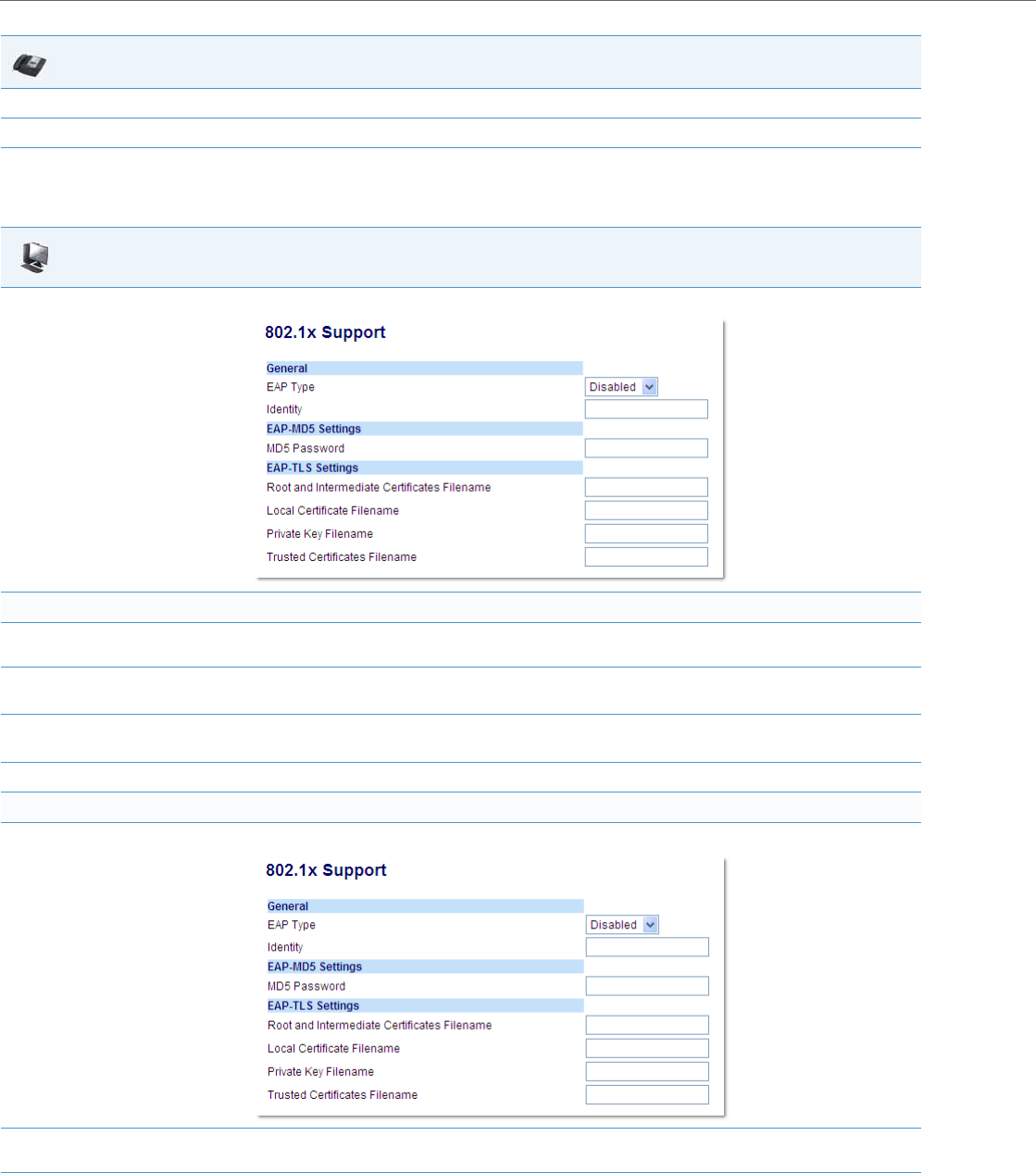
Advanced Operational Features
6-24 41-001343-02 REV04 – 05.2014
Configuring the 802.1x Protocol Using the Aastra Web UI
Use the following procedure to configure the 802.1x Protocol on your phone using the Aastra Web UI.
9. Press the Save softkey.
10. Restart the phone for the selection to take affect.
Aastra Web UI
1. Click on Advanced Settings->802.1x Support.
To configure EAP-MD5:
2. In the “EAP Type” field, select EAP-MD5.
Valid values are: Disabled (Default), EAP-MD5, and EAP-TLS.
3. In the “Identify” field, enter an Identity for the IP phone for which you are configuring 802.1x.
For example, phone1.
4. In the “MD5 Password” field, enter a password used for the MD5 authentication of the phone.
For example, password1.
5. Click Save Settings to save your changes.
To configure EAP-TLS:
1. Click on Advanced Settings->802.1x Support.
1. In the “EAP Type” field, select EAP-TLS.
Valid values are: Disabled (Default), EAP-MD5, and EAP-TLS.
2. In the “Identity” field, enter an Identity for the IP phone for which you are configuring 802.1x.
For example, phone1.
IP Phone UI
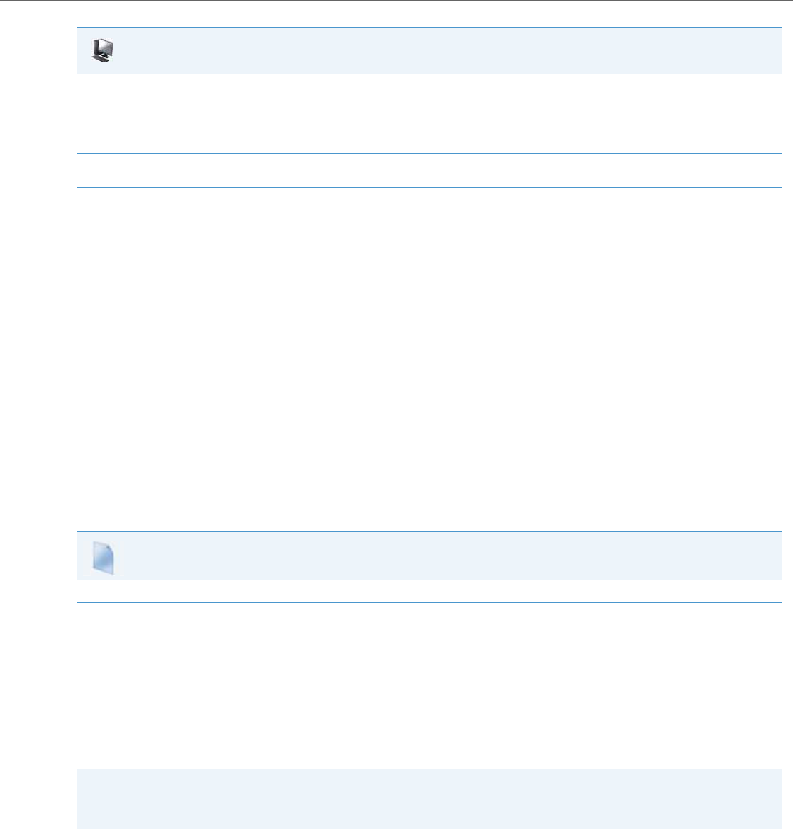
Advanced Operational Features
41-001343-02 REV04 – 05.2014 6-25
Symmetric UDP Signaling
By default, the IP phones use symmetric UDP signaling for outgoing UDP SIP messages. When symmetric UDP is enabled,
the IP phone generates and listens for UDP messages using port 5060.
You can manually disable symmetric UDP signaling using the IP phone’s configuration file. When you disable symmetric
UDP signaling, then the IP phone chooses a random source port for UDP messages.
The IP phone also chooses a random source port for UDP messages to the registrar if you configure a backup registrar
server. Likewise, the IP phone chooses a random source port for UDP messages with regards to communication with the
respective proxy server if you configure a backup proxy server or backup outbound proxy server. If you configure a backup
registrar server as well as a backup proxy server and/or a backup outbound proxy server, one random source port will be
used for all UDP messages (i.e. for communication with the proxy server[s] and for registration).
An Administrator can configure symmetric UDP signaling using the configuration files only.
Configuring Symmetric UDP Signaling Using the Configuration Files
You use the following parameter to enable or disable Symmetric UDP Signaling in the configuration files:
•sip symmetric udp signaling
Symmetric TLS Signaling
The IP phones also use symmetric TLS signaling for outgoing TLS SIP messages by default. When symmetric TLS is enabled,
the IP phone uses port 5061 as the persistent TLS connection source port.
Administrators can manually disable symmetric TLS signaling using the IP phone’s configuration files. When you disable
symmetric TLS signaling, the IP phone chooses a random persistent TLS connection source port from the TCP range (i.e.
49152...65535) for TLS messages after each reboot regardless of whether the parameter sip outbound support is enabled
or disabled.
An Administrator can configure symmetric TLS signaling using the configuration files only.
3. In the “Root and Intermediate Certificates Filename” field, enter the filename that contains the root and intermediate certificates related
to the local certificate. For example: root_Intermed_certifi.pem.
4. In the “Local Certificate Filename” field, enter the filename that contains the local certificate. For example: localcertificate.pem.
5. In the “Private Key Filename” field, enter the filename that contains the private key. For example: privatekey.pem.
6. In the “Trusted Certificates Filename” field, enter the filename that contains the trusted certificates. For example:
trusted_certificates.pem.
7. Click Save Settings to save your changes.
Configuration Files
For the specific parameter you can set in the configuration files, see Appendix A, the section, “Symmetric UDP Signaling Setting” on pageA-210.
Note:
If multiple persistent TLS connections are required, the persistent TLS connection source ports will follow the structure
of random_port, random_port + 1, random_port + 2, etc....
Aastra Web UI

Advanced Operational Features
6-26 41-001343-02 REV04 – 05.2014
Configuring Symmetric TLS Signaling Using the Configuration Files
You use the following parameter to enable or disable Symmetric TLS Signaling in the configuration files:
•sips symmetric tls signaling
Removing UserAgent and Server SIP Headers
Currently, the phone always configures the SIP UserAgent/Server headers to contain:
Aastra <PhoneModel>/<FirmwareVersion>
You can suppress the addition of these headers by using the following parameter in the configuration files:
•sip user-agent
Setting this parameter allows you to enable or disable the addition of the User-Agent and Server SIP headers from the
SIP stack.
You can configure this feature using the configuration files only.
Configuring UserAgent/Server SIP Headers
You use the following parameter to specify whether the UserAgent and Server SIP header is added to the SIP stack.
•sip user-agent
Configuration Files
For the specific parameter you can set in the configuration files, see Appendix A, the section, “Symmetric TLS Signaling Setting” on pageA-210.
Configuration Files
For the specific parameter you can set in the configuration files, see Appendix A, the section, “User-Agent Setting” on pageA-210.

Advanced Operational Features
41-001343-02 REV04 – 05.2014 6-27
GRUU and sip.instance Support
Globally Routable User-Agent URIs (GRUUs) provide a way for anyone on the Internet to route a call to a specific instance
of a User-Agent.
The IP phones provide GRUU support using draft-ietf-sip-gruu-15. A sip.instance is added to all non-GRUU contacts. By
default, this feature is enabled. You can enable or disable this support using the configuration files.
Limitations of the GRUU Feature
The following are limitations of the GRUU feature on the phones:
•GRUU-Draft-15 is not compatible with versions prior to GRUU-Draft-10.
•Phones do not support temporary or phone-created GRUUs.
Enabling/Disabling GRUU and sip.instance Support
Use the following procedure to enable/disable GRUU and sip.instance support.
Multi-Stage Digit Collection (Billing Codes) Support (for Sylantro Servers)
The IP Phones support Multi-Stage Digit Collection (billing codes) for Sylantro Servers. Sylantro Server features, like man-
datory and optional billing codes, requires that the application server notify the phone to collect more digits before com-
pleting the call. The IP phone is able to collect digits in two stages to support the billing code feature.
Aastra IP Phone users are prompted to enter the correct billing code when they dial these numbers:
•External numbers.
•Eternal numbers dialed using a Speed Dial key.
Billing Codes Implementation Notes
Note the following implementation information:
•IP phone users may enter a 2-9 digit billing code. Billing codes may not start with either 0 (Operator) or 9 (external calls).
•When using Sylantro Click-to-Call, IP phone users select a billing code from a pull-down menu.
•When placing a call, a secondary dial tone alerts IP phone users to enter the billing code. The IP phone UI also displays a
“Enter Billing Code” message.
•If an IP phone user redials a number, they do not have to re-enter the billing code. The billing code information is main-
tained and processed accordingly.
•If an IP phone user enters an invalid billing code, the call fails.
Mandatory versus Optional Billing Codes
This release of the Aastra IP phones supports two types of billing codes: Mandatory and Optional. The Sylantro server con-
figuration determines which type of billing code is used on the IP phones.
•Mandatory billing codes: Calls are not connected until the user enters a valid billing code. The user dials the phone
number. When prompted for billing codes, user dials the billing code.
For example, suppose the IP phone user is using billing code 300, and dialing the external number 617-238-5500. The IP
user then enters the number using the following format:
–6172385000#300
Configuration Files
For the specific parameter you can set in the configuration files, see Appendix A, the section, “GRUU and sip.instance Support” on pageA-211.

Advanced Operational Features
6-28 41-001343-02 REV04 – 05.2014
Using mandatory billing codes, if the user is configuring a Speed Dial number, then they enter the number using the
following format:
–<phonenumber>%23<billingcode>
To use this format with the default dial plan terminator (#), the # sign required by Sylantro as a delimiter should be
represented as an escaped character by using the sequence %23. The speed dial format for an external number that
includes a mandatory billing code becomes:
–<phonenumber>%23<billing code>
•Optional billing codes: The user dials an optional billing code by dialing *50, followed by the billing code digits.
When prompted for additional digits, user enters the phone number.
For example, suppose the IP phone user is using billing code 500, and dialing the external number 617-238-5000. The
IP user then enters the number using the following format:
–*50500#6172385000
If the user is dialing configuring a Speed Dial number, then they enter the number using the following format:
–*50<billingcode>#<phonenumber>
To use this format with the default dial plan terminator (#), the # sign required by Sylantro as a delimiter should be
represented as an escaped character by using the sequence %23. The speed dial format for an external number that
includes an optional billing code becomes:
–*50<billing code>%23<phone number>
Numbers Not Requiring Billing Codes
Billing codes are not required for the following two types of calls:
•Emergency calls (E911)
•Calls between extensions
Configurable DNS Queries
The domain name system (DNS) is the way that Internet domain names are located and translated into Internet Protocol
addresses. A domain name is a meaningful and easy-to remember identifier for an Internet address.
The lists of domain names and IP addresses are distributed throughout the Internet in a hierarchy of authority within a
database of records. There is usually a DNS server within close proximity to your geographic location that maps the
domain names in your Internet requests or forwards them to other servers in the Internet.
The IP Phones may be configured to issue requests for DNS records using one of three methods. In the first method, the
IP phones issue requests for “A” records from the DNS server. In the second method, the IP phones issue requests for
“SRV” records from the DNS server. In the third method, the IP phones issue requests for NAPTR records from the DNS
server. However, the IP phones do not use the NAPTR record to determine whether to use a secure or unsecure commu-
nication path (see the following table for a description of each method).
When the IP phone accesses the IP network, it issues a DNS lookup request to find the IP address and port and then waits
for a response from the DNS service that provides the IP address and port.
Note:
Whether or not the phone will operate/communicate in a secure or unsecure mode is ONLY determined by the pre-
provisioning of the phone (i.e. the .cfg file).

Advanced Operational Features
41-001343-02 REV04 – 05.2014 6-29
You can configure the phone to use any one of these methods by entering the applicable value in the configuration files:
Configuring the DNS Query Method
You can configure the DNS query method for the phone to use for performing DNS lookups using the following parameter
in the configuration files:
•sip dns query type
Ignore Out of Sequence Errors
An Administrator can configure the phone via the “sip accept out of order requests” parameter to ignore CSeq number
errors on all SIP dialogs on the phone. When this parameter is enabled, the phone no longer verifies that the sequence
numbers increase for each message within a dialog, and does not report a "CSeq Out of Order" error if they do not
increase.
An Administrator can enable/disable this feature using the configuration files only.
Configuration
File Value DNS Server Method Used Description
0 A only The phone issues requests for “A” (Host IP Address) records from the DNS server to get the IP
address, and uses the default port number of 5060.
1 SRV & A The phone issues requests for “SRV” (Service Location Record) records from the DNS server to get
the port number. Most often, the IP address is included in the response from the DNS server to
avoid extra queries. If there is no IP address returned in the response, the phones send out the
request for “A” records from the DNS server to find the IP address.
2 NAPTR & SRV & A First, the phone sends "NAPTR" (Naming Authority Pointer) lookup to get the “SRV” pointer and
service type. For example, if Global SIP transport protocol on the phone is “UDP”, and Proxy server
on the phone is “test.aastra.com”, then:
1. If the NAPTR record is returned empty, the phone will use the default value “_sip._udp.test.aas-
tra.com" for the “SRV” lookup.
2. If the NAPTR record is returned "test.aastra.com SIP+D2U .... _sip._udp.abc.aastra.co m", the
phone will use “_sip._udp.abc.aastra.com" for the “SRV” lookup.
3. If the NAPTR record is returned "test.aastra.com SIP+D2T .... _sip._tcp.test.aastra.com", where
the service type TCP mismatches the phone configured transport protocol “UDP”, the phone will
ignore this value and use the default value “_sip._udp.test.aastra.com" for the “SRV” lookup.
Note:
The phone does not use the service type sent by the NAPTR response to switch its transport pro-
tocol, nor does it use the NAPTR response to determine whether to use a secure or unsecure com-
munication path. The phone will always use a global sip protocol that is configured on the phone
via configuration files or the web user interface.
After performing NAPTR, the phone sends “SRV” lookup to get the IP address and port number. If
there is no IP address in the “SRV” response, then it sends out an “A” lookup to get it.
Note:
On the phone side, if you configure the phone with a Fully- Qualified Domain Name (FQDN) proxy and specified port,
the phone always sends “A only” lookups to find the Host IP Address of the proxy.
Configuration Files
For the specific parameter you can set in the configuration files, see Appendix A, the section, “DNS Query Setting” on pageA-211.
Note:
As the default Asterisk configuration does not fully track dialogs through a reboot, it is recommended that this param-
eter be enabled when using the BLF feature with an Asterisk server. If you do not enable this feature, then rebooting the
Asterisk server may cause BLF to stop working. With this parameter enabled, the BLF key starts working again when the
phone re-subscribes, which by default, are one hour apart.

Advanced Operational Features
6-30 41-001343-02 REV04 – 05.2014
Enabling/Disabling “Out of Order SIP Requests”
Use the following procedure to enable/disable “out of order SIP requests”.
“Early-Only” Parameter in Replaces Header RFC3891
The phones support the “early-only” parameter in the “Replaces” header as referenced in RFC3891. When the phone
receives a Replaces header with the early-only parameter, it replaces the existing dialog if the call is still in the early state.
If the call has been answered, then the Replaces request is rejected.
Switching Between Early Media and Local Ringing
Previous to release 2.6, the phone generated a local ring tone when receiving a 180 response unless early media was
being played, regardless of SDP. The local ring tone stopped when the first RTP packet was received in the early session.
The local ring tone did not resume when it received subsequent 180 responses, even though early media was not being
received.
In Release 2.6 and up, the phone supports switching between early media and local ring tone. Upon receiving a 180
response, the phone now generates a local ring tone unless it is receiving an early media flow. If the phone receives any
subsequent 180 responses, it regenerates the local ring tone unless it is receiving early media flow.
Enable Microphone During Early Media
The phones now allow Administrators to enable or disable the microphone during early media by configuring the “sip
early media mute mic” parameter. Early media indicates the period when a call has not fully established (i.e. the far end
has not answered the call). By enabling this parameter, Administrators can mute the microphone during early media to
prevent the far end from listening into the call prior to answering it.
Enabling/Disabling “Microphone During Early Media”
Use the following procedure to enable/disable “microphone during early media:
“Call-Info” Header to 200ok Responses for Shared Call Appearance (SCA)
Lines
In earlier versions of the IP phone software releases, a "Call-Info" header was only added to the requests generated by
the phone for Shared Call Appearance (SCA) lines. A “Call-Info” header ia now also included in the 200ok response to an
INVITE, RE-INVITE, and UPDATE messages for SCA lines. No configuration is required for this feature.
Configuration Files
For the specific parameter you can set in the configuration files, see Appendix A, the section, “Ignore Out of Order SIP Requests” on pageA-212.
Note:
This feature is not supported in outgoing requests.
Configuration Files
For the specific parameter you can set in the configuration files, see Appendix A, the section, “Enable Microphone During Early Media” on pageA-147.

Advanced Operational Features
41-001343-02 REV04 – 05.2014 6-31
Reason Header Field in SIP Message
The IP Phones support the receiving of the Reason Header Field in a SIP CANCEL message, as described in RFC3326. This
allows a call that is answered from somewhere else to still display in the Callers List. Also, the missed calls indicator and
counter do not change.
Limitation
If the call is answered somewhere else, the duration of the call does not display in the Callers List.
Call Failed Message
Administrators can place certain restrictions on users for making outgoing calls (for example, only allow national calls, only
allow internal calls, only allow emergency calls, etc.). Previously when a restriction was active and a user dialed a number
that was not allowed, the PBX sent a certain status code 4xx and the phone displayed “Call Failed” or “Busy”, which was not
very informative to the user.
Now when an outgoing call fails with a status code 4xx or 5xx, the phone will look for the Reason Header (RFC 3326) in the
status message and display the Reason Header to the user. The reason text is displayed in the center of the screen and is
limited to 20 characters.
If there is a Reason Header in the status code message, the reason text (if any) will be displayed on the phone. The tone that
is played follows the status code (i.e., the busy tone for 486 and 503, and the call failed tone for all others).
If there is no Reason Header in the status message, the behaviour of the phone should be unchanged:
•“Busy” is displayed for the status codes 486 and 503 (SERVICE UNAVAILABLE) and the busy tone will be played,
•or “Call Failed” is displayed for status codes 4xx to 5xx and the call failed tone will be played,
•or “Not Configured” or “Seize Failed” is displayed in case of an internal error,
•or “Unavailable” is displayed in case of code less support (6735i, 6767i, 6755i, 6757i, 6757i CT, 6867i, 9480i, and 9480i CT
phones only).
Configurable “Allow” and “Allow-Event” Optional Headers
On the IP Phones, an Administrator can enable or disable whether or not the optional “Allow” and “Allow-Events” headers
are included in the NOTIFY message from the phone.
SIP NOTIFY messages from the phone may contain optional headers called “Allow” and “Allow-events”. If the NOTIFY mes-
sage contains these headers, the UDP packet returned by the server may be too large and may fragment the packet. To
prevent the fragmenting of the UDP packet, the “Allow” and “Allow-events” headers may be removed using the parameter,
“sip notify opt headers”. If this parameter is set to “0” (disabled), the optional headers are not included in the SIP NOTIFY
message which reduces the size of the packet returned by the server, and prevents fragmentation of the packet.
The value set for this parameter specifies whether or not to include the optional headers in the SIP NOTIFY message from
the phone.
An Administrator can enable/disable the optional “Allow” and “Allow-Event” headers using the following parameter in the
configuration files:
•sip notify opt headers
Enabling/Disabling Optional “Allow” and “Allow-Event” Headers
Use the following procedure to enable/disable “Allow” and “Allow-Event” headers.
Configuration Files
For the specific parameter you can set in the configuration files, see Appendix A, the section, “Optional “Allow” and “Allow-Event” Headers” on pageA-
212.

Advanced Operational Features
6-32 41-001343-02 REV04 – 05.2014
Configurable SIP P-Asserted Identity (PAI)
The IP Phones support a private extension to SIP for Asserted Identity within trusted networks (as defined in RFC 3325).
This feature allows a network of trusted SIP servers to assert the identity of authenticated users, and verify that phone
messages originate from a Trusted Identity. Upon receiving a message from a caller in the Trusted Network, the IP phone
reads the contents of the P-Asserted-Identity (PAI) header field and displays it on the phone UI. This field contains a more
accurate description of the caller identity (extension/phone number) than is contained in the SIP message.
When an IP phone receives an incoming call, the IP phone performs the following actions:
•Checks to see if the incoming call is from a registered proxy server.
•If the call is forwarded via a registered proxy server, then the message has already been verified and authenticated by
the server. The caller is part of the Trust Network. The IP phone UI displays the caller information contained in the PAI
header.
•If the call is not forwarded via a registered proxy server - and therefore is not a “Trusted Entity” - the IP phone UI does
not display any trust information contained in the PAI header.
The phones provide the ability for the Administrator to enable or disable the display of P-Asserted Identity (PAI) informa-
tion on the phone using the following parameter in the configuration files:
•sip pai
Enabling/Disabling P-Asserted Identity (PAI)
Use the following procedure to enable/disable PAI.
Notes:
•The phones support PAI header in the UPDATE message, according to draft-ietf-sipping-update-pai-00. This feature
is always enabled.
•If an UPDATE is received with a PAI header from a trusted source, the phone updates the display with this information.
The phone ignores any PAI received from untrusted entities.
Configuration Files
For the specific parameter you can set in the configuration files, see Appendix A, the section, “P-Asserted Identity (PAI)” on pageA-212.

Advanced Operational Features
41-001343-02 REV04 – 05.2014 6-33
Configurable Route Header in SIP Packet
The IP Phones support the following parameter:
•sip remove route
This parameter enables or disables the addition of the Route header in a SIP packet. Enable this parameter for outbound
proxies that do not support Route headers.
Enabling/Disabling the Route Header in the SIP Packet
Use the following procedure to enable/disable the addition of the Route header in the SIP packet.
Configurable Compact SIP Header
The phones provide a feature that allows an Administrator to shorten the length of a SIP packet by using the compact
form. This feature is in accordance with Compact SIP Headers defined in RFC 3261.
For example, the following SIP header is the long format:
Via: SIP/2.0/UDP 10.50.91.2:5060;branch=z9hG4bK571ebe0c;rport=5060;received=10.50.91.2
From: "Unknown" <sip:Unknown@10.50.91.2>;tag=as19d00fc8
To: <sip:1106@10.50.110.54:5060;transport=udp>;tag=916699998
Call-Id: 73cad5456806f3a7768d17e8617279d7@10.50.91.2
CSeq: 102 OPTIONS
The following SIP header is equivalent to the above SIP header, but uses the short (compact) format instead:
v: SIP/2.0/UDP 10.50.91.2:5060;branch=z9hG4bK571ebe0c;rport=5060;received=10.50.91.2
f: "Unknown" <sip:Unknown@10.50.91.2>;tag=as19d00fc8
t: <sip:1106@10.50.110.54:5060;transport=udp>;tag=916699998
i: 73cad5456806f3a7768d17e8617279d7@10.50.91.2
CSeq: 102 OPTIONS
By default, the IP Phones use the long format. However, an Administrator can provision the short (compact) format using
the configuration files. The Aastra Web UI does not support this configuration feature.
Enabling/Disabling the Compact SIP Headers Feature
Use the following procedure to enable/disable the Compact SIP Header in the SIP packet.
Reject INV or BYE when Unsupported Value in REQUIRE Header
The IP Phones support the following parameter:
•sip enforce require hdr
Note:
When enabled this will break all support for SIP routing, so if some other device in the network attempts to add itself
to the route it will fail.
Configuration Files
For the specific parameter you can set in the configuration files, see Appendix A, the section, “Route Header in SIP Packet” on pageA-213.
Configuration Files
For the specific parameter you can set in the configuration files, see Appendix A, the section, “Compact SIP Header” on pageA-213.

Advanced Operational Features
6-34 41-001343-02 REV04 – 05.2014
This parameter allows you to enable (1) or disable (0) the rejection of an INV or BYE with a “420 Bad Extension” if the INV
or BYE contains an unsupported value in the REQUIRE header.
Enabling/Disabling a Rejection of the INV or BYE
Use the following procedure to enable/disable the rejection of the INV or BYE if the INV or BYE contains an unsupported
value in the REQUIRE header.
XML URI for Key Press Simulation
The phones provide a feature that allow an XML Developer or Administrator to define XML Key URIs that can send key
press events to the phone, just as if the physical hard key, softkey, or programmable key were pressed on the phone.
When the Key URI event is sent from the server to the phone, the phone initiates the event as if the key was physically
pressed. If the key is not present on the phone (hard key) or not available (softkey or programmable key), when the
phone receives the URI, the event is discarded. If you are in the process of changing the softkey or programmable key
setting, or the key is disabled while the event is being processed, the request is discarded. The phone maps key events to
its physical keys and not to its mapped logical keys.
The following table identifies the XML URIs for pressing buttons on the phone..
Configuration Files
For the specific parameter you can set in the configuration files, see Appendix A, the section, “Rejection of INV or BYE” on pageA-213.
XML Key URI Description
Line Keys
Key:Line1 to Key:Line<n> Line 1 to <n>Keys
Note:
The phone ignores URI line key events if the line keys are not physically present on
the phone.
Keypad Keys
Key:KeyPad0 to Key:KeyPad9 Numeric Keypad Keys 0-9
Key:KeyPadStar * - Star Key
Key:KeyPadPound # Hash Key
Softkeys
Key:SoftKey1 to Key:SoftKey<n> Softkey 1 to <n> (valid softkeys depend on the number of physical softkeys on the
phone)
Key:TopSoftKey1 to Key:TopSoftKey<n> top Top softkeys 1 to <n> ((valid top softkeys depend on the number of physical top
softkeys on the phone)
Programmable Keys
Key:PrgKey1 to Key:PrgKey<n> Programmable keys 1 to <n> (valid programmable keys depend on the number of
physical programmable keys on the phone)
Expansion Module Keys
Key:ExpMod1SoftKey1 to Key:ExpMod1SoftKey<n> Expansion module 1 softkeys 1 to <n> (valid softkeys depend on the number of
physical softkeys on the expansion module)
Note:
The phone ignores URI expansion module key events if the keys are not physically
present on the expansion module.
Key:ExpMod2SoftKey1 to Key:ExpMod2SoftKey<n> Expansion module 2 soft keys 1 to <n> (valid softkeys depend on the number of
physical softkeys on the expansion module)

Advanced Operational Features
41-001343-02 REV04 – 05.2014 6-35
Key:ExpMod3SoftKey1 to Key:ExpMod3SoftKey<n> Expansion module 3 soft keys 1 to <n> (valid softkeys depend on the number of
physical softkeys on the expansion module)
Volume Key
Key:VolDwn Volume Decrease Key
Key:VolUp Volume Increase Key
Feature Keys
Key:Xfer Transfer Key
Key:Conf Conference Key
Key:Services Services Key
Key:Intercom Intercom Key
Key:Headset Headset Key
Note:
For Headset URI key, the behavior will be as if the "speaker/headset" key is
pressed; and does not switch to headset for headset key event or to speaker for
speaker key event.
Key:Speaker Speaker Key
Note:
For Speaker URI key, the behavior will be as if the "speaker/headset" key is pressed;
and does not switch to headset for headset key event or to speaker for speaker key
event.
Key:Mute Mute Key
Key:Hold Hold Key
Key:Redial Redial Key
Key:Callers Callers Key
Key:Directory Directory Key
Key:Options Options Key
Key:Save Save Key
Key:Delete Delete Key
Key:Swap Swap Key
Key:Goodbye GoodBye Key
Navigation Keys
Key:NavUp Navigation Up Key
Key:NavDwn Navigation Down Key
Key:NavLeft Navigation Left Key
Key:NavRight Navigation Right Key
Function Keys (only if physically configured on the phone or expansion module)
KeyPark Park Softkey
KeyPickup Pickup Softkey
Notes:
•If the URI key is a valid key, the phone executes the key regardless of the current state on the phone.
•Park and Pickup XML URI softkeys are available ONLY if these features are physically configured on the phone or
expansion module.
XML Key URI Description

Advanced Operational Features
6-36 41-001343-02 REV04 – 05.2014
Examples
There are two ways to format the XML key URI:
For XML Post Messages
<ExecuteItem URI="<XML Key URI>" />
Example:
<ExecuteItem URI="Key: Line1" />
For XML Key Scripts
<URI><XML Key URI></URI>
Example:
<URI>Key: Line1</URI>
<SoftKey index="1">
<Label>Keypad1</Label>
<URI>Key: Line1</URI>
</SoftKey>
Domain Name System (DNS) Server Pre-caching Support
The IP phones now support the use of a local DNS host file to resolve DNS queries, and supports pre-provisioning of DNS
SRV records. This feature allows administrators to configure the phone to download a text file which contains persistent
DNS “A record” hostname to IP address mappings. In addition, support for persistent DNS “SRV records” has been added
to permit SRV based high availability of services.
There are two methods used to configure DNS pre-caching on the IP phone:
•Configure a unix style “host” file used instead of a DNS “A query” to resolve hostnames to IP addresses. The host file is
downloaded and cached on the IP phone.
•Configure DNS “SRV queries” for geographic redundancy and failover. The configured SRV entries are used to pre-load
the DNS cache on the IP phone.
Both these methods are configurable using the configuration files only, and are primarily intended for use when a third
party hosting provider delivers SIP services but does not have local access or control of the LAN side DNS infrastructure.
Configuring DNS “Host File” Pre-caching from the Configuration Server
The DNS host file must reside on the same server as the configuration files (aastra.cfg/.tuz, etc.) and the filename to
download is specified within the configuration.
Use the following parameter to configure the phone to use the host file for host IP address lookups.
The following procedure is an example of how to use the “sip dns host file” parameter to configure DNS lookup pre-cach-
ing from the configuration server.
Note:
Time-to-Live (TTL) used in this feature is hard-coded for each server and not configurable.
Configuration Files
For the specific parameter you can set in the configuration files, see Appendix A, the section, “DNS Host File” on pageA-214.

Advanced Operational Features
41-001343-02 REV04 – 05.2014 6-37
Configuring “DNS Host” Pre-caching
Configuring DNS “Service (SRV) Records” Pre-caching
In addition to using a host file to resolve host names to IP addresses, an Administrator can also configure DNS “SRV
records” (Service Records) for geographic redundancy and failover between application servers in the network.
The SIP registration and SIP proxy features on the phones previously allowed the use of server queries only to live DNS
servers. Using the host file and specific DNS SVR parameters extends this mechanism to allow pre-configuration of server
values in the aastra.cfg file. The following new parameters are used for this feature:
•sip dns srvX name
•sip dns srvX priority
•sip dns srvX weight (supported in a future release)
•sip dns srvX port
•sip dns srvX target
You can configure up to 4 DNS SRV records, with each server having a priority which tells the phone which server to use,
and a host name or target. The IP phone will use the DNS SRV record with the lowest-numbered priority value first, and
will only failover to other records if the connection with this record's host fails. Thus a service may have a designated
failover server, which is only used if the primary server fails.
If a service has multiple SRV records with the same priority value, the IP phone(s) use the weight field to determine which
host to use. The weight value is a ratio compared to the weight of other records with the same name and priority value.
1. Using a text-based editing application, create a blank text file
2. Enter the IP addresses of the DNS servers in your local network. For example:
1.2.3.4 server1
5.6.7.8 server2
9.0.1.2 server3
Note:
Ensure each line uses a Carriage Return (CR) or Carriage Return + Line Feed (CRLF) to terminate the line.
3. Save the file as “<filename>.txt”. F o r ex am p le , “hostfile.txt”.
4. Using a text-based editing application, open the aastra.cfg file for the phone(s) for which you want to apply the DNS hostfile.
5. Enter the following parameter in the aastra.cfg file followed by the host file name as the value:
sip dns host file: <filename>.txt
For example:
sip dns host file: hostfile.txt
Note:
If using a text file on a PC to enter this value, you must enter a carriage return (CR) after entering the host file name.
6. Save the file. Make sure the aastra.cfg and the hostfile.txt files are on the configuration server in your network before downloading to the
phone(s).
7. Restart the phone(s) in your network.
The phone(s) downloads the specified host text file and stores it locally on the phone’s flash memory. Upon each subsequent boot of the
phones, if the host text file is available on the configuration server, it is downloaded to replace the locally cached copy; otherwise, the pre-
viously cached copy is retained and used unchanged.
The configuration of the phone(s) can now use server1, server2, or server3 for SIP or other services instead of using the IP addresses. The
phones will continue resolving the host names even if DNS on the network has conflicting or missing entries for server1, server2, or server3,
or if the local LAN DNS server fails to respond.
Note:
The “X” indicates a DNS SRV with a value from 1 to 4.
Note:
The “sip dns srvX weight” parameter must be configured but the phones will support this feature in a future release.

Advanced Operational Features
6-38 41-001343-02 REV04 – 05.2014
In the following example, both the priority and weight fields are used to provide a combination of load balancing and
backup service.
Example
sip dns srv1 name: _sip._udp.example.com
sip dns srv1 priority: 10
sip dns srv1 weight: 60
sip dns srv1 port: 5060
sip dns srv1 target: bigbox.example.com
sip dns srv2 name: _sip._udp.example.com
sip dns srv2 priority: 10
sip dns srv2 weight: 20
sip dns srv2 port: 5060
sip dns srv2 target: smallbox1.example.com
sip dns srv3 name: _sip._udp.example.com
sip dns srv3 priority: 10
sip dns srv3 weight: 20
sip dns srv3 port: 5060
sip dns srv3 target: smallbox2.example.com
sip dns srv4 name: _sip._udp.example.com
sip dns srv4 priority: 20
sip dns srv4 weight: 10
sip dns srv4 port: 5060
sip dns srv4 target: backupbox.example.com
The first three records (SRV 1, 2, and 3) share a priority of 10, so the weight field's value is used by the phones to load bal-
ance across the three target host names.
Bigbox will get 60% of the load, and smallbox1 and smallbox2 will each get 20% load.
If all three servers with priority 10 are unavailable, the next highest priority record is selected, in this case backupbox.
This could be a server in another physical location.
The server entries in the aastra.cfg file can use DNS hostnames or can use IP addresses. If hostnames are used, any pre-
cached DNS A records via the host file mechanism are used before resorting to live DNS query if there is no local match.
For example, the following hostfile.text uses IP addresses that are used in the DNS server queries:
hostfile.txt
192.168.2.3 bigbox.example.com
192.168.3.4 smallbox1.example.com
192.168.8.1 smallbox2.example.com
47.28.05.69 backupbox.example.com
Use the following procedure in the configuration files to configure DNS server query support for the phones.
Use the following procedure to configure DNS SRV record pre-caching.
Configuration Files
For the specific parameter you can set in the configuration files, see Appendix A, the section, “DNS Server Query” on pageA-214.

Advanced Operational Features
41-001343-02 REV04 – 05.2014 6-39
Configuring DNS SRV Record Pre-caching
1. Using a text-based editing application, open the aastra.cfg file.
2. Enter the parameter, “sip dns srvX name”, where “X” is a value from 1 to 4.
Enter a value for the DNS SRV service URI. For example:
sip dns srv1 name: _sip._udp.example.com
3. Enter the parameter, “sip dnx srvX priority, where “X” is a value from 1 to 4.
Enter a value for the DNS server priority. Valid values are 0 to 65535. Default is 0. For example:
sip dns srv1 priority: 10
After this parameter is downloaded from the configuration server to the phone, the phone uses the DNS server with the lowest numbered
priority first to perform DNS lookups.
4. Enter the parameter, “sip dnx srvX weight, where “X” is a value from 1 to 4.
Enter a value for the DNS server weight. Valid values are 0 to 65535. Default is 0. For example:
sip dns srv1 weight: 60
Note:
The “sip dns srv1 weight” parameter must be configured but will be supported in a future release.
5. Enter the parameter, “sip dnx srvX port, where “X” is a value from 1 to 4.
Enter a value for the port number on the target host. Valid values are 0 to 65535. Default is 0. For example:
sip dns srv1 port: 5060
6. Enter the parameter, “sip dnx srvX target, where “X” is a value from 1 to 4.
Enter a value for the DNS server target. Valid values are the host name or a fully qualified domain name. For example:
sip dns srv1 target: bigbox.example.com
7. Save and close the file.
8. Place the aastra.cfg file on the configuration server and download to the phones.

Advanced Operational Features
6-40 41-001343-02 REV04 – 05.2014
Configurable Transport Protocol for SIP Services and RTCP Summary
Reports
Parameters have been implemented allowing administrators the ability to independantly configure the transport proto-
cols used by SIP services (e.g. the SIP XML Notify service) and RTCP summary reports. The following parameters are avail-
able to be defined in the configuration files:
SIP Services
•sip services transport protocol
•sip services port
The above parameters are used to specify the transport protocol and port used for SIP services.
RTCP Summary Reports
•sip rtcp summary reports transport protocol
The above parameter is used to specify the transport protocol used for RTCP summary reports.
Use the following procedure in the configuration files to configure the transport protocol for SIP services and RTCP sum-
mary reports.
Configurable Alphanumeric Input Order for Username Prompts
A configuration parameter username alphanumeric input order is available for the 6730i, 6731i, 6753i , 6863i, 6865i,
and 9143i IP phones allowing administrators the ability to change the default behavior of the keypad input order during
username prompts. . By default, keypad input order during username prompts changes from uppercase letters to the
respective digit and then to lowercase letters with each successive press of the key. For example, when pressing “2” on
the keypad, the following will be input with each successive press:
Note:
•The parameter "sip symmetric udp signaling" is effective when the transport protocol for RTCP summary reports is
set to be UDP. For more information on symmetric udp signaling, refer to Symmetric UDP Signaling on page 6-25.
•When the SIP transport protocol is set to TCP and the RTCP summary reports transport protocol is set to UDP, if an
outbound proxy is configured, all SIP requests including RTCP summary reports will be sent over TCP.
•In cases where the SIP services transport protocol is the same as the SIP transport protocol or RTCP summary reports
transport protocol, only the SIP services port is enabled (the phone listens on the SIP services port as well as the local
SIP port if they are different [if they are the same, no extra action is needed]).
Configuration Files
For the specific parameter you can set in the configuration files, see Appendix A, the section, “SIP Services/RTCP Summary Reports Transport Protocol
Settings” on pageA-216.
# of Presses Letter/Number
1A
2B
3C
42
5a
6b
7c

Advanced Operational Features
41-001343-02 REV04 – 05.2014 6-41
When the username alphanumeric input order parameter is defined as “1”, the respective digit will be available as the
first input option followed by upper case and then lower case letters. For example, when pressing “2” on the keypad with
this parameter enabled, the following will be input with each successive press:
The behavior of the username alphanumeric input order parameter is applicable to the following username prompts as
displayed on the phone’s UI:
•HTTPS Login User Name
•SIP User Name
•SIP Display Name
•SIP Auth. Name
•FTP User Name
Use the following procedure in the configuration files to configure the keypad input order for username prompts.
# of Presses Letter/Number
12
2A
3B
4C
5a
6b
7c
Note:
The parameter is set to “0” (uppercase letters first) by default.
Configuration Files
For the specific parameter you can set in the configuration files, see Appendix A, the section, “Alphanumeric Input Order for Username Prompts” on
pageA-217.
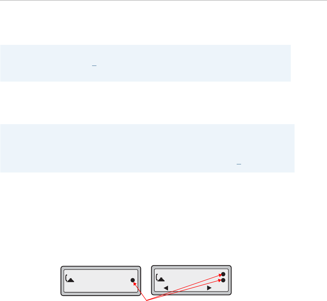
Advanced Operational Features
6-42 41-001343-02 REV04 – 05.2014
Active Voice-over-IP (VoIP) Recording
Active VoIP recording is supported by the IP phones. When using the IP phones with an Aastra call manager supporting
voice recording and a recording system with the predefined subset of the SIP interface, administrators can configure the
phones to send duplicate copies of the transmit and receive RTP or SRTP voice packets to the voice recording system.
Both dynamic (i.e. per call) and static (i.e. per the duration that the phone is registered) recording sessions are supported
by the IP phones. Additionally, administrators have the option of enabling a Record-On-Demand feature allowing users
to initiate and terminate a call recording session at their discretion. The call recording sessions are initiated by the voice
recording system and when the session is established, the IP phone will duplicate all of its incoming and outgoing
RTP/SRTP packets and send them to the voice recording system where they can be archived and analyzed as required.
Administrators must configure a whitelist for voice recording system authentication using the “recorder addressN”
parameters (where N is a number from 1 to 6). These parameters are used to specify trusted IP addresses corresponding
to the voice recording system. The IP phone will check and respond to SIP messages coming from these IP addresses. If
all of these parameters are left undefined, the active VoIP recording feature is disabled.
A whitelist can also be configured for RTP/SRTP packet destination authentication using the “recording destinationN”
parameters (where N is a number from 1 to 6). These parameters are used to specify trusted IP addresses corresponding
to the destination where the RTP/SRTP packets should be sent. The IP phone will check to see if the destination IP
addresses are trusted before sending the duplicated RTP/SRTP packets. If all of these parameters are left undefined, no
authentication checks will be performed.
When a recording session is in progress, the respective IP phones display the following recording icons on screen:
Notes:
•Currently, the active VoIP recording feature is only supported when using the Aastra MX-ONE call manager (v4.1 or
5.0) in conjunction with ASC’s EVOip 10.0 voice recording system. Support for additional call managers and voice
recording systems will be implemented in future releases.
•The active VoIP recording feature is disabled by default.
Notes:
•Please contact your Aastra MX-ONE account manager for details on how to configure and utilize the Record-On-
Demand feature.
•As the RTP/SRTP packets sent to the voice recording system are duplicate copies, the codec used for the original call as
well as the recording are identical as well. If active VoIP recording is required, ensure that the IP phone is configured to
use the G.711 or G.729 codec as these are currently the only two codecs supported by ASC’s EVOip 10.0 voice recording
system.
Martin Croft
402
00:53
1
1. Martin Croft
2. Dave Brundle
1
Leave Drop
3-Line LCDs
Normal Call Conference Call
Recording Icons
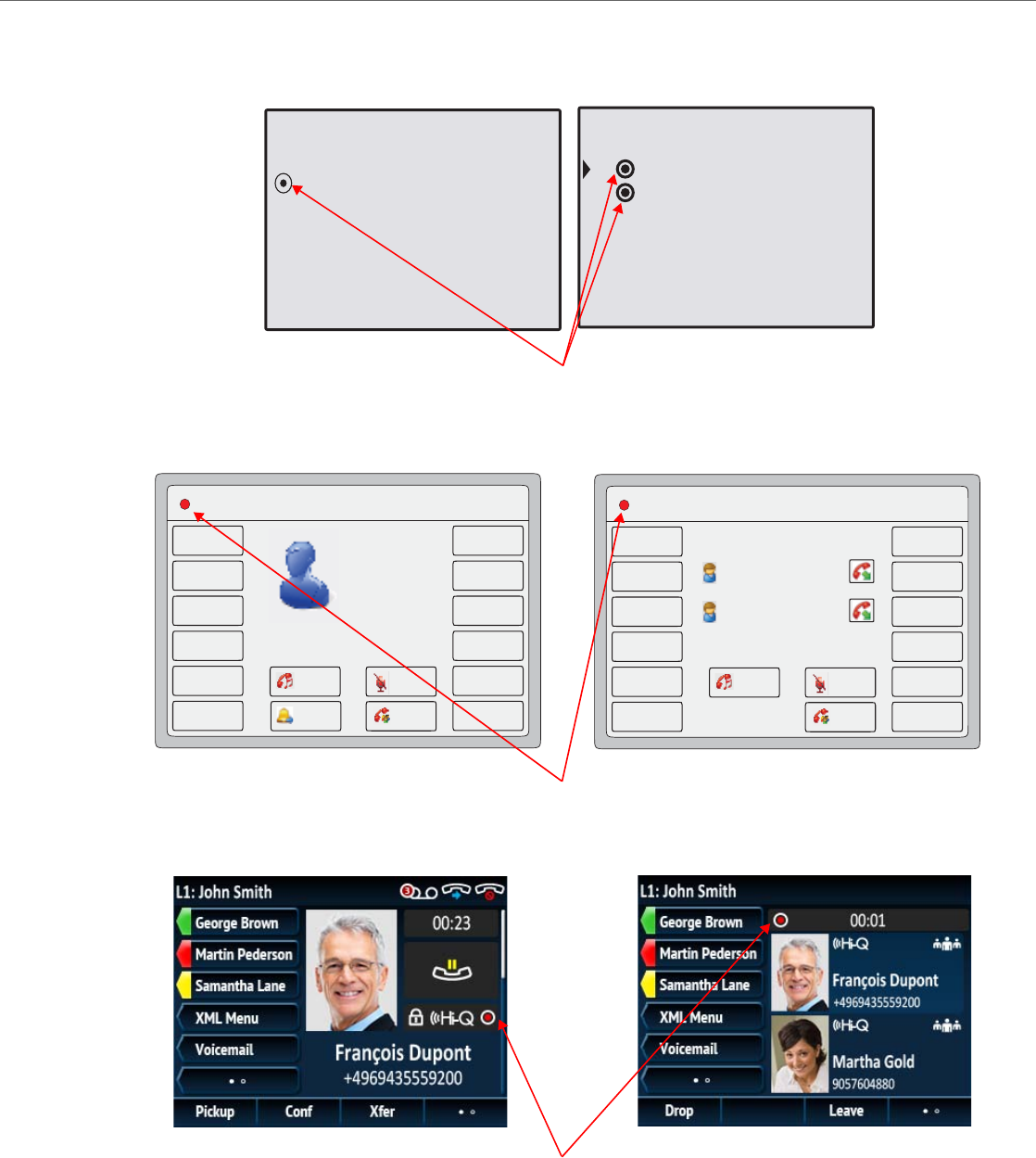
Advanced Operational Features
41-001343-02 REV04 – 05.2014 6-43
00:53
402
Martin Croft
L1 Lewis Button
Drop
Conf
Xfer
L1 Lewis Button
2. Dave Brundle
1. Martin Croft
Leave
Drop
8 and 11-Line LCDS
Normal Call Conference Call
Recording Icons
L1 Lewis Button 12 : 45pm
Mon Jan 1
Home
DND
Call Forward
Hold
Conf
Mute
Martin Croft
402
00:53
Transfer
L1 Lewis Button 12 : 45pm
Mon Jan 1
Home
DND
Call Forward
Hold
Leave
Mute
Martin Croft
402
Dave Brundle
404
6739i
Normal Call Conference Call
Recording Icons
6867i
Normal Call Conference Call
Recording Icons

Advanced Operational Features
6-44 41-001343-02 REV04 – 05.2014
Moreover, the phone will, by default, play a periodic audible beep tone through the selected audio path notifying users
that their call is being recorded. Playback of the beep tone is configurable and if required, administrators can disable or
set the playback interval of the beep tone by defining the “recording periodic beep” parameter in the configuration
files. Additionally, by utilizing the “recording beep direction“ parameter, administrators can define whether the beep
tone is audible locally, remotely, or both.
Use the following procedure in the configuration files to configure the active VoIP recording feature.
BroadSoft BroadWorks Executive and Assistant Services Feature
The 6730i, 6731i, 6753i, 6755i, 6757i, 6757i CT, 9143i, 9840i, and 9840i CT IP phones support the BroadSoft BroadWorks
Executive and Assistant Services feature. The Executive and Assistant Services feature allows Administrators to create an
inter-network relationship between Executives and Assistants allowing calls to the Executive’s phone to be screened, fil-
tered, and routed to an Assistant, whereby the Assistant can answer, divert the filtered call, or push the call back to the
Executive.
Configuration Parameters
After configuring the applicable options on the BroadSoft Broadworks call manager Web portal, Administrators must
define the newly introduced “sip execassist filter call prefix”, “sip execassist fac call push”, a n d “sip execassist fac ini-
tiate call” parameters for the phone.
The “sip execassist filter call prefix” parameter is used to identify the prefix of the Alerting Custom Calling Line ID
Name of a filtered call. The Alerting Custom Calling Line ID Name as configured in the BroadWorks Web portal should fol-
low the format:
[prefix] [Identifier] -> [Executive Name]
Warning!
The recording icon is displayed on the IP phones to indicate the recording session is active and that a duplicate copy
of the RTP/SRTP stream is to be sent from the phone to the recording server. The overall recording and its quality is
dependent on the recording server and the network.
Note:
In addition to the aforementioned parameters corresponding to the active IP voice recording feature, the transport pro-
tocol parameters for SIP services (i.e. “sip services transport protocol” and “sip services port”) must also be defined in
the configuration files. See “Configurable Transport Protocol for SIP Services and RTCP Summary Reports” on page6-40
for more information.
Configuration Files
For the specific parameter you can set in the configuration files, see Appendix A, the section, “Active VoIP Recording Settings” on pageA-218.
Note:
This feature is not supported for the 6735i, 6737i, 6863i, 6865i, and 6867i in Release 3.3.1 SP3.
Notes:
•The inter-network relationship is created dynamically through the BroadSoft BroadWorks call manager Web portal.
For BroadSoft BroadWorks Executive and Assistant Services Web portal configuration details and procedures, please
refer to the respective BroadSoft documentation.
•For details on how to configure and utilize the BroadSoft BroadWorks Executive and Assistant Services feature from
a user’s perspective, please refer to the respective phone model’s Aastra SIP IP Phone User Guide.

Advanced Operational Features
41-001343-02 REV04 – 05.2014 6-45
The Executive Name must match the name that is configured in the user’s profile, separated by a space or comma.
For example, if the “Alerting Custom Calling Line ID Name” setting in the BroadWorks Web portal is defined as “[F] Filtrage
-> Dupont, Francois”, the From header of a filtered call sent by the BroadWorks SIP INVITE message will look similar to:
From:”[F] Filtrage -> Dupont, Francois"
<sip:5551234567@as.aastra.com;user=phone>
The “sip execassist filter call prefix”parameter in this scenario could be defined as:
sip execassist filter call prefix: "[F]"
The Assistant’s phone will parse the From header of the SIP INVITE message of an incoming call sent by the call manager
and will identify whether or not the call is a filtered call by the prefix. The prefix itself is not displayed on the phone’s screen
(e.g. in the case outlined above, the phone will only display “Filtrage -> Dupont, Francois”).
The “sip execassist fac call push” parameter is used to specify the Feature Access Code (FAC) that is used to push a filtered
call from the Assistant’s phone back to the Executive’s phone. The FAC should correspond to the value configured for the
“Executive-Assistant Call Push” setting defined in the BroadSoft Web portal.
The “sip execassist fac initiate call” parameter is used to specify the FAC that is used by Assistants to initiate a call on
behalf of the Executive. The FAC should correspond to the value configured for the “Executive-Assistant Initiate Call” set-
ting defined in the BroadSoft Web portal.
Use the following procedure in the configuration files to configure the BroadSoft BroadWorks Executive and Assistant
Services feature.
Filter Softkey
In addition to the parameters, the “Filter” softkey type has been introduced allowing both Executives and Assistants the
ability to easily activate and deactivate the Executive Call Filtering feature.
Filter Softkey for the Executive’s Phone
The Executive’s phone requires that only one Filter softkey be configured. The Filter softkey’s value can either be left unde-
fined (which will toggle the Executive Call Filtering settings on the call manager via the SIP SUBSCRIPTION/NOTIFY mecha-
nism) or, it can be defined using the following values (which will toggle the settings via an FAC call):
•Executive Call Filtering Activation FAC (e.g. “#61”)
–Used when the Deactivation FAC is in the same format as the Activation FAC but sequentially one number above the
Activation FAC. For example, if the softkey value is defined as #61 (the Activation FAC), the phone will automatically
assume that the Deactivation FAC is “#62” and will use that code to deactivate Executive Call Filtering.
•Executive Call Filtering Activation FAC followed by a semi-colon and then Executive Call Filtering Deactivation FAC (e.g.
“#61;*61” or “#61;#71”)
–
Used when the Activation and Deactivation FACs are not in the same format or when they are not sequential. For
example, if the Activation FAC is configured in the BroadSoft BroadWorks Web portal is “#61” and the Deactivation FAC
is configured as “*61” or “#71”, the softkey value should be defined with the two specific FACs separated by a semi-
Note:
The Alerting Calling Line ID Number can either be configured as the Executive’s Number or Originator’s Number.
Configuration Files
For the specific parameter you can set in the configuration files, see Appendix A, the section, “BroadSoft BroadWorks Executive and Assistant Services
Settings” on pageA-219.
Notes:
•The As-Feature Event Subscription option must also be enabled for the Filter softkey to function. This feature can be
enabled by defining the “sip lineN as-feature-event subscription” parameter as “1” in the configuration files (where
“N” corresponds to the applicable line) or through the phone’s Web UI under Advanced Settings > LineN >
Advanced SIP Settings > As-Feature-Event Subscription. Refer to As-Feature-Event Subscription on page 6-11 for
additional details on the As-Feature Event Subscription feature.
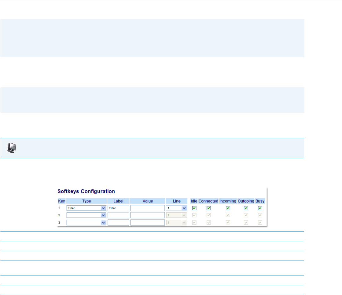
Advanced Operational Features
6-46 41-001343-02 REV04 – 05.2014
colon (i.e. “#61;*61” or “#61;#71” respectively).
Irrespective of a defined or undefined key value, when the Filter softkey is pressed, Executive Call Filtering will be acti-
vated and the softkey’s corresponding LED will be lit. When the Filter softkey is pressed again, Executive Call Filtering will
deactivate and the softkey’s corresponding LED will turn off.
Configuring the Filter Softkey on the Executive’s Phone Using the Aastra Web UI
Use the following procedure to configure the
Filter Softkey on the Executive’s phone
using the Aastra Web UI:
Configuring the Filter Softkey on the Executive’s Phone Using the Configuration Files
To configure the Filter softkey on the Executive’s phone using the configuration files, you must enter “filter” for the key
type. For the label (8 and 11-line phones only), enter a key label to assign to the Filter key (e.g. “Filter”). Defining the value
is optional. If you prefer to toggle Executive Call Filtering using an FAC call, enter in the Executive Call Filtering Activation
FAC (e.g. “#61”) or both the Executive Call Filtering Activation and Deactivation FACs followed by a semi-colon (e.g.
“#61;*61”) for the value. For the line setting, enter the line number for which you want to use the key functionality.
The following parameters are examples you can use to configure the Filter softkey on the Executive’s phone:
For Softkeys
softkey1 type: filter
softkey1 label: Filter
softkey1 value: “#61;*61”
softkey1 line: 1
Notes:
•If the Deactivation FAC is not specified after the semi-colon (e.g. “#61;”), the phone will ignore the semi-colon and
behave as if only the Activation FAC was defined (i.e. the phone will automatically assume that the Deactivation FAC
is in the same format but sequentially one number above the Activation FAC.
•The IP phones support Executive Call Filtering Activation/Deactivation FACs that contain the prefix “#” or “*”.
Note:
Upon a reboot, the initial state of the Filter softkey LED will correspond to the Executive Call Filtering state configured
on the call manager.
Aastra Web UI
1. Click on Operation->Softkeys and XML.
or
Click on Operation-> Programmable Keys.
or
Click on Operation->Expansion Module Keys.
2. Select a key that you want to use as a Filter activate/deactivate key.
3. In the "Type" field, select "Filter".
4. In the "Label" field (8 and 11-line phones only), enter a label to apply to this key (e.g. Filter).
5. (Optional) In the "Value" field, enter the Executive Call Filtering Activation FAC (e.g. #61) or both the Executive Call Filtering Activation and
Deactivation FACs followed by a semi-colon (e.g. #61;*61).
6. In the “Line” field, select the line for which you want to use the key functionality.
7. Click Save Settings to save your settings.
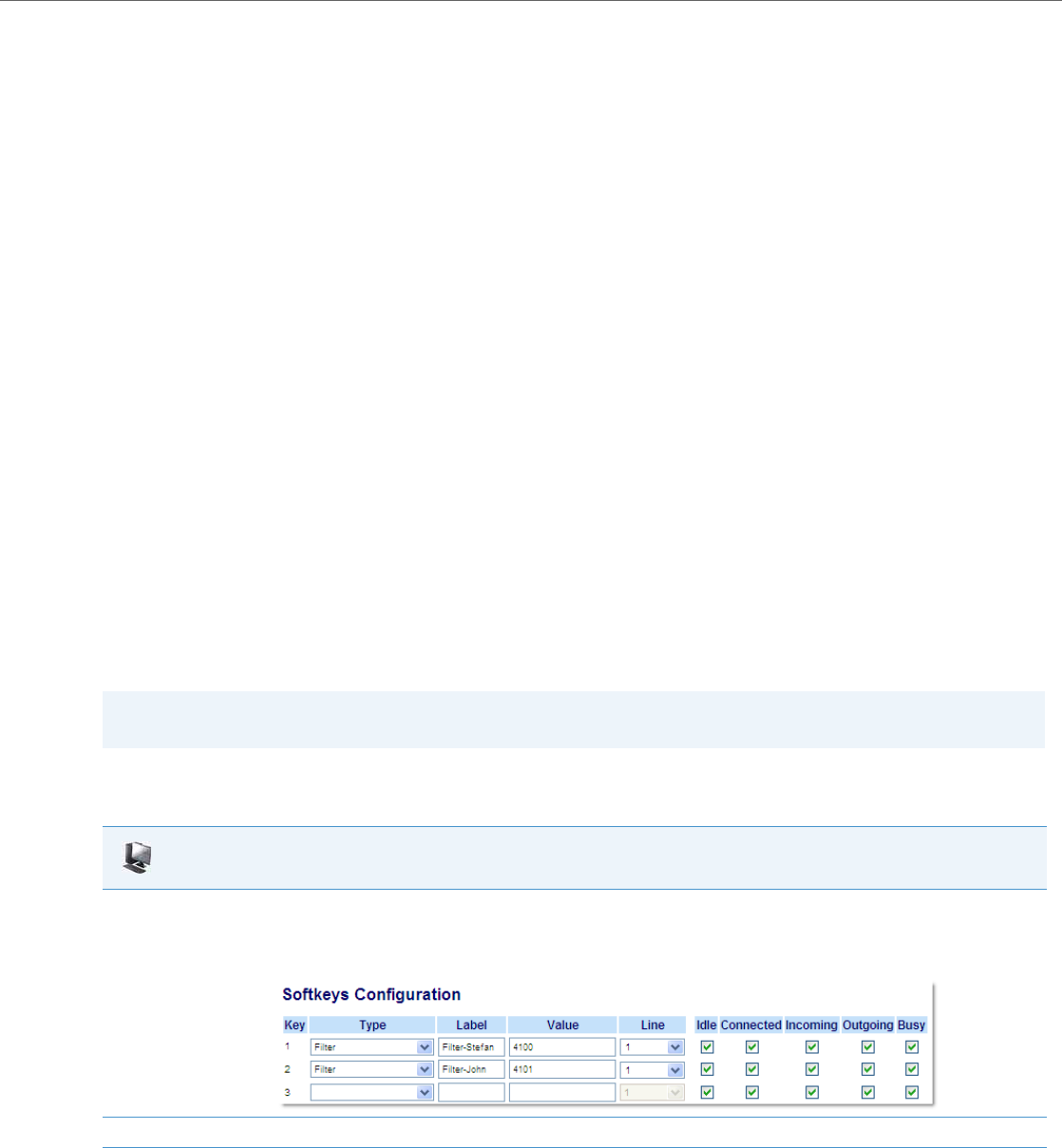
Advanced Operational Features
41-001343-02 REV04 – 05.2014 6-47
For Programmable Keys
prgkey1 type: filter
prgkey1 value: “#61;*61”
prgkey1 line: 1
For Top Softkeys
topsoftkey1 type: filter
topsoftkey1 label: Filter
topsoftkey1 value: “#61;*61”
topsoftkey1 line: 1
For Expansion Module Softkeys
expmod1 key1 type: filter
expmod1 key1 label: Filter
expmod1 key1 value: “#61;*61”
expmod1 key1 line: 1
Filter Softkey for the Assistant’s Phone
As an Assistant can be associated with multiple Executives simultaneously, the Assistant’s phone can be configured with
multiple Filter softkeys; one softkey for each Executive. In this case, the value of each Filter softkey should correspond to
the phone number or extension of the respective Executive as per configured in the user’s profile.
When Filter softkeys are configured with key values, pressing the respective Filter softkey will activate Executive Call Filter-
ing for the applicable Executive and the softkey’s corresponding LED will be lit. When the same Filter softkey is pressed
again, Executive Call Filtering for the applicable Executive will deactivate and the softkey’s corresponding LED will turn off.
Alternatively, a single Filter softkey can be configured without a defined key value. If this is the case, the Assistant will be
able to manually activate and deactivate Executive Call Filtering for each associated Executive through the phone’s UI. In
this scenario, as only one Filter softkey is utilized, the softkey’s corresponding LED will be lit when Executive Call Filtering is
activated for even one associated Executive. If Executive Call Filtering is disabled for all associated Executives, the softkey’s
corresponding LED will turn off.
Configuring the Filter Softkey on the Assistant’s Phone Using the Aastra Web UI
Use the following procedure to configure the
Filter Softkey on the Assistant’s phone
using the Aastra Web UI:
Note:
If Call Forward is enabled for filtered calls, LEDs for all Filter softkeys will be turned off.
Aastra Web UI
1. Click on Operation->Softkeys and XML.
or
Click on Operation-> Programmable Keys.
or
Click on Operation->Expansion Module Keys.
2. Select a key that you want to use as a Filter activate/deactivate key.
3. In the "Type" field, select "Filter".

Advanced Operational Features
6-48 41-001343-02 REV04 – 05.2014
Configuring the Filter Softkey on the Assistant’s Phone Using the Configuration Files
To configure the Filter softkeys on the Assistant’s phone using the configuration files, you must enter “filter” for the key
types. For the labels (8 and 11-line phones only), enter key labels to assign to the Filter key (e.g. “Filter-Stefan” for a spe-
cific Executive or simply “Filter” for a generic Filter key with no defined value). Defining the value is optional. If you
choose to assign a Filter softkey and define values for each Executive, enter in the respective Executive’s phone or exten-
sion number (e.g. 4100). For the line setting, enter the line number for which you want to use the key functionality. If you
prefer to utilize a single Filter softkey without a defined value you will be able to manually activate and deactivate Execu-
tive Call Filtering for each Executive to whom the Assistant is assigned through the phone’s UI.
The following parameters are examples you can use to configure multiple Filter softkeys corresponding to multiple Exec-
utives on the Assistant’s phone:
For Softkeys
softkey1 type: filter
softkey1 label: Filter-Stefan
softkey1 value: 4100
softkey1 line: 1
softkey2 type: filter
softkey2 label: Filter-John
softkey2 value: 4101
softkey2 line: 1
For Programmable Keys
prgkey1 type: filter
prgkey1 value: 4100
prgkey1 line: 1
prgkey2 type: filter
prgkey2 value: 4101
prgkey2 line: 1
For Top Softkeys
topsoftkey1 type: filter
topsoftkey1 label: Filter-Stefan
topsoftkey1 value: 4100
topsoftkey1 line: 1
topsoftkey2 type: filter
topsoftkey2 label: Filter-John
topsoftkey2 value: 4101
4. In the "Label" field (8 and 11-line phones only), enter a label to apply to this key (e.g. Filter-Stefan for a specific Executive or simply Filter for
a generic Filter key with no defined value).
Note:
To utilize a single Filter softkey without a defined key value (so that you can manually activate and deactivate Executive Call Filtering through
the phone’s UI) skip to Step 8.
5. (In the "Value" field, enter the Executive’s phone or extension number (e.g. 4100)
6. In the “Line” field, select the line for which you want to use the key functionality.
7. Repeat Steps 2 to 6 for each respective Executive for whom you would like to assign a Filter key.
8. Click Save Settings to save your settings.
Aastra Web UI
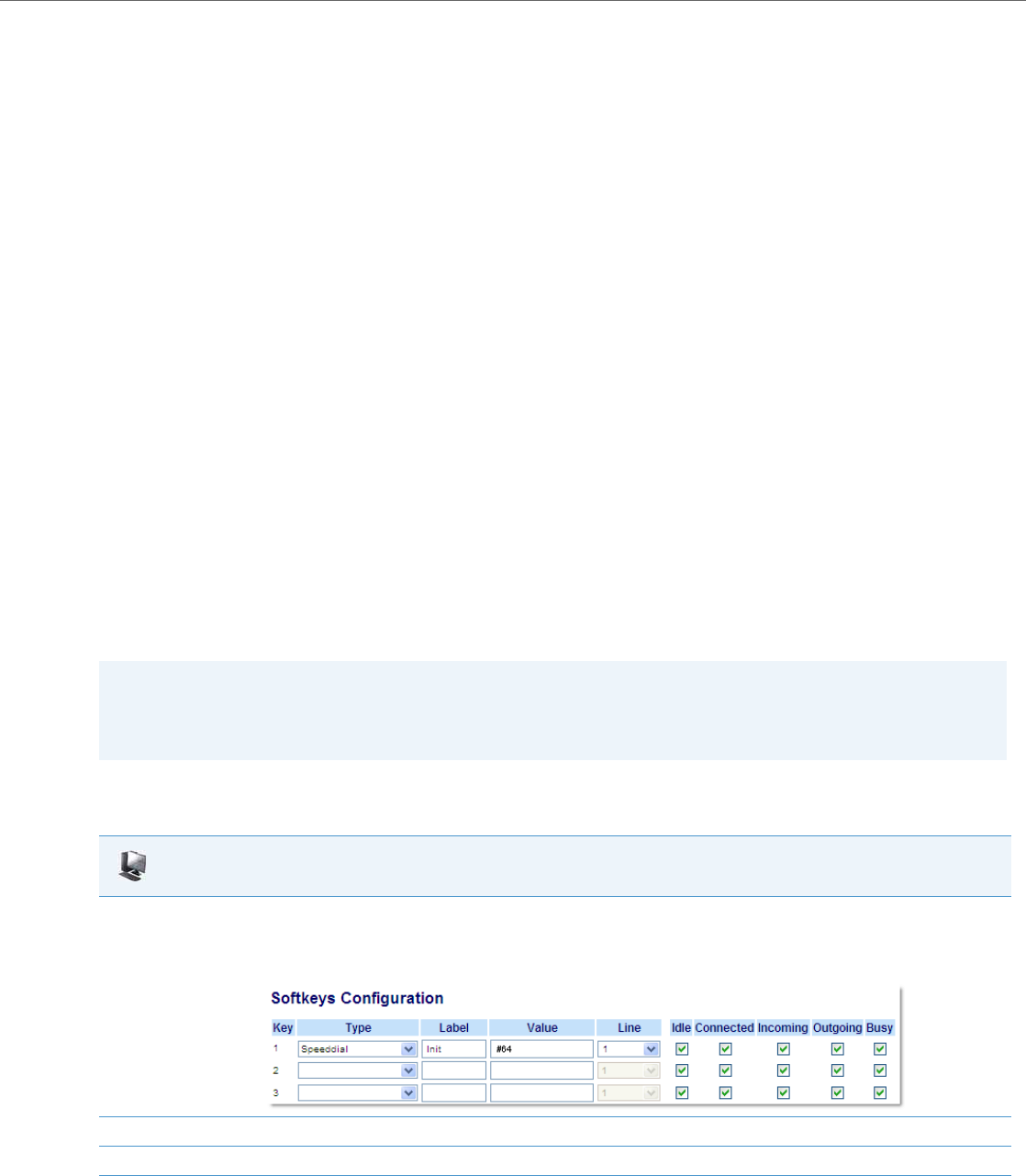
Advanced Operational Features
41-001343-02 REV04 – 05.2014 6-49
topsoftkey2 line: 1
For Expansion Module Softkeys
expmod1 key1 type: filter
expmod1 key1 label: Filter-Stefan
expmod1 key1 value: 4100
expmod1 key1 line: 1
expmod1 key2 type: filter
expmod1 key2 label: Filter-John
expmod1 key2 value: 4101
expmod1 key2 line: 1
Speeddial Softkey with Initiate Call Functionality (Assistants Only)
Speeddial softkeys can be configured to efficiently utilize the Executive-Assistant Initiate Call function. With a Speeddial
softkey configured for this feature, Assistants can initiate a call on behalf of an Executive, whereby the call will appear to
the target as one originated by the Executive himself/herself. The Speeddial softkey’s value can be defined using the fol-
lowing syntax:
•Executive-Assistant Initiate Call FAC (e.g. “#64”):
–In such scenarios, the call manager will play an audible prompt asking you to enter the Executive’s Address and Des-
tination Address manually using the keypad.
•Executive-Assistant Initiate Call FAC followed by the Executive’s Address (e.g. “#644052”):
–
In such scenarios,
only the Destination Address will need to be manually entered using the keypad.
•Executive-Assistant Initiate Call FAC, followed by the Executive’s Address, an asterisk, and then the Destination Address
(e.g. “#644052*4059”):
–In such scenarios, addresses will not need to be manual entered and the phone will automatically initiate the call to
the target phone on behalf of the Executive.
Configuring the Initiate Call Softkey on the Assistant’s Phone Using the Aastra Web UI
Use the following procedure to configure the
Initiate Call Softkey on the Assistant’s phone
using the Aastra Web UI:
Note:
The Speeddial softkey type can be utilized for additional functions related to the Executive and Assistant Services fea-
ture that rely on FAC calls (i.e. opting in to an Executive’s filtered call pool, opting out of an Executive’s filtered call pool,
etc...). Administrators simply need to configure the Speeddial key value as the FAC and label accordingly.
Aastra Web UI
1. Click on Operation->Softkeys and XML.
or
Click on Operation-> Programmable Keys.
or
Click on Operation->Expansion Module Keys.
2. Select a key that you want to use as an Initiate Call key.
3. IIn the "Type" field, select "Speeddial".
4. In the "Label" field (8 and 11-line phones only), enter a label to apply to this key (e.g. Init).
Advanced Operational Features
6-50 41-001343-02 REV04 – 05.2014
Configuring the Initiate Call Softkey on the Assistant’s Phone Using the Configuration Files
To configure the Initiate Call Speeddial softkeys on the Assistant’s phone using the configuration files, you must enter
“speeddial” for the key types. For the labels (8 and 11-linephones only), enter key labels to assign to the Speeddial key
(e.g. “Init”). For the values, enter one of the following:
•Executive-Assistant Initiate Call FAC (e.g. “#64”)
•Executive-Assistant Initiate Call FAC followed by the Executive’s Address (e.g. “#644052”)
•Executive-Assistant Initiate Call FAC, followed by the Executive’s Address, an asterisk, and then the Destination
Address (e.g. “#644052*4059”)
For the line setting, enter the line number for which you want to use the key functionality.
The following parameters are examples you can use to configure multiple Initiate Call Speeddial softkeys:
For Softkeys
softkey1 type: speeddial
softkey1 label: Init
softkey1 value: “#64”
softkey1 line: 1
softkey2 type: speeddial
softkey2 label: Init2
softkey2 value: “#644052”
softkey2 line: 1
softkey3 type: speeddial
softkey3 label: Init3
softkey3 value: “#644052*4059”
softkey3 line: 1
For Programmable Keys
prgkey1 type: speeddial
prgkey1 value: “#64”
prgkey1 line: 1
prgkey2 type: speeddial
prgkey2 value: “#644052”
prgkey2 line: 1
prgkey3 type: speeddial
prgkey3 value: “#644052*4059”
prgkey3 line: 1
For Top Softkeys
topsoftkey1 type: speeddial
topsoftkey1 label: Init
5. In the "Value" field, enter the Initiate Call FAC (e.g. #64)
or
In the "Value" field, enter the Initiate Call FAC, followed by the Executive’s Address (e.g. #644052)
or
In the "Value" field, enter the Initiate Call FAC, the Executive’s Address, followed by an asterisk, and then the Destination Address (e.g.
#644052*4059)
6. In the “Line” field, select the line for which you want to use the key functionality.
7. Click Save Settings to save your settings.
Aastra Web UI

Advanced Operational Features
41-001343-02 REV04 – 05.2014 6-51
topsoftkey1 value: “#64”
topsoftkey1 line: 1
topsoftkey2 type: speeddial
topsoftkey2 label: Init2
topsoftkey2 value: “#644052”
topsoftkey2 line: 1
topsoftkey3 type: speeddial
topsoftkey3 label: Init3
topsoftkey3 value: “#644052*4059”
topsoftkey3 line: 1
For Expansion Module Softkeys
expmod1 key1 type: speeddial
expmod1 key1 label: Init
expmod1 key1 value: “#64”
expmod1 key1 line: 1
expmod1 key2 type: speeddial
expmod1 key2 label: Init2
expmod1 key2 value: “#644052”
expmod1 key2 line: 1
expmod1 key2 type: speeddial
expmod1 key2 label: Init3
expmod1 key2 value: “#644052*4059”
expmod1 key2 line: 1

7-1 41-001343-02 REV04 – 05.2014
Chapter 7
Encrypted Files on the IP Phone
About this Chapter
This chapter provides information about encryption on the IP phones and provides methods an administrator can use to
store encrypted files to a server.
Topics
This chapter covers the following topics:
Top ic Page
Encrypted Files on the IP Phone page7-2
Configuration File Encryption Method page7-2
Procedure to Encrypt Configuration Files page7-3
Vendor Configuration File Encryption page7-4

Encrypted Files on the IP Phone
41-001343-02 REV04 – 05.2014 7-2
Encrypted Files on the IP Phone
An encryption feature for the IP phone allows Service Providers the capability of storing encrypted files on their server to
protect against unauthorized access and tampering of sensitive information (i.e., user accounts, login passwords, registra-
tion information). Service Providers also have the capability of locking a phone to use a specific server-provided configura-
tion only.
Configuration File Encryption Method
Only a System Administrator can encrypt the configurations files for an IP Phone. System Administrators use a password
distribution scheme to manually pre-configure or automatically configure the phones to use the encrypted configuration
with a unique key.
From a Microsoft Windows command line, the System Administrator uses an Aastra-supplied configuration file encryption
tool called "anacrypt.exe" to encrypt the <mac>.tuz file.
This tool processes the plain text <mac>.cfg, <model>.cfg, and aastra.cfg files and creates triple-DES encrypted versions
called <mac>.tuz, <model>.tuz, and aastra.tuz. Encryption is performed using a secret password that is chosen by the
administrator.
The encryption tool is also used to create an additional encrypted tag file called security.tuz, which controls the decryption
process on the IP phones. If security.tuz is present on the TFTP/FTP/HTTP server, the IP phones download it and use it
locally to decrypt the configuration information from the aastra.tuz and <mac>.tuz files. Because only the encrypted ver-
sions of the configuration files need to be stored on the server, no plain-text configuration or passwords are sent across
the network, thereby ensuring security of the configuration data.
To make changes to the configuration files, the System Administrator must save the original files.
The security feature described above prevents unauthorized parties from reading or writing the contents of the
<MAC>.tuz file. It also provides the following:
•Prevents users from using the <MAC>.tuz file that does not match the user’s phone MAC address.
•Renders the <MAC>.tuz file invalid if the user renames the file.
•Works with IP phone releases prior to Release 2.2.
•Provides compatibility between the previous encryption routine and the new decryption routine.
Note:
Aastra also supplies encryption tools to support Linux platforms (anacrypt.linux) if required.
Note:
If the use of encrypted configuration files is enabled (via security.tuz or pre-provisioned on the IP phone) the aastra.cfg,
<model>.cfg, and <mac>.cfg files are ignored, and only the encrypted equivalent files aastra.tuz, <model>.tuz, and
<mac>.tuz are read.

Encrypted Files on the IP Phone
7-3 41-001343-02 REV04 – 05.2014
Procedure to Encrypt Configuration Files
To encrypt the IP phone configuration files (using a Microsoft Windows OS):
C:\> anacrypt.exe -h
Provides encryption of the configuration files used for the
family of Aastra IP phones.
Copyright (c) 2005-2012, Aastra Technologies, Ltd.
Usage:
anacrypt {infile.cfg|-d <dir>} [-p password] [-m] [-i] [-v] [-h]
Examples
The following examples illustrate the use of the anacrypt.exe file.
Example 1
Generating a security.tuz file with password 1234abcd:
For firmware version 3.3.1 (enhanced security):
C:\>anacrypt -i -p 1234abcd -v3
1. Obtain the anacrypt encryption tool (anacrypt.exe) from your Aastra representative.
2. Open a command line window application (i.e. DOS window).
3. At the prompt, enter anacrypt.exe and press <Return>.
4. Enter a command utilizing the details provided in the help screen.
Anacrypt Switch Description
{infile.cfg | -d <dir>} Specifies that all .cfg files in <dir> should be encrypted.
[-p password] Specify password used to generate keys.
-m Generate MAC.tuz files that are phone specific. This switch generates files that are
only usable for phones with firmware version 2.2.0 and above.
-v1 Specifies the version of encryption that the anacrypt tool uses. Use version 1 encryption (i.e. -v1) to generate files that
are readable by all model phones.
-v2 (Default) Specifies the version of encryption that the anacrypt tool uses. Use version 2 encryption (i.e. -v2) to generate
files that are readable by phones with firmware 2.2.0 and above.
-v3 (Enhanced security version) Specifies the version of encryption that the anacrypt tool uses. Use version 3 encryption
(i.e. -v3) to generate files that are readable by phones with firmware 3.3.1 and above.
-i Generate security.tuz file.
-h Show the help screen.
Notes:
•Configuration files that are encrypted using v3 encryption can only be decoded by phones on Release 3.3.1 (and
above).Customers with v3-encrypted configuration files will lose the ability to decode the files (and in turn will lose
all previously configured settings) if they downgrade their phones to any firmware release prior to 3.3.1.
•An incorrect password produces garbage. For site-specific keyfile security.cfg the plaintext must match the pass-
word.

Encrypted Files on the IP Phone
41-001343-02 REV04 – 05.2014 7-4
For firmware version 2.2.0 and above:
C:\>anacrypt -i -p 1234abcd
or
C:\>anacrypt -i -p 1234abcd -v2
For any firmware version:
C:\>anacrypt -i -p 1234abcd -v1
Example 2
Encrypting a single aastra.cfg file with password 1234abcd (for firmware version 3.3.1):
C:\>anacrypt aastra.cfg -p 1234abcd -v3
Example 3
Encrypting a <mac>.cfg file with password 1234abcd (for firmware version 3.3.1):
C:\>anacrypt 00085d000000.cfg -p 1234abcd -v3
Example 4
Encrypting a <mac>.cfg file with password 1234abcd using MAC encryption (for firmware version 3.3.1):
C:\>anacrypt 00085d000000.cfg -m -p 1234abcd -v3
Example 5
Encrypting all cfg files in C:\data with password 1234abcd using MAC encryption and generating a security.tuz file at the
same time (for firmware version 3.3.1):
C:\>anacrypt -d C:\data -p 1234abcd -m -i -v3
Example 6
Encrypting all cfg files in C:\data with password 1234abcd and generating a security.tuz file at the same time (for firmware
version 3.3.1):
C:\>anacrypt -d C:\data -p 1234abcd -i -v3
Vendor Configuration File Encryption
Some vendors can have specific methods to encrypt files on their configuration servers. For each phone, the configuration
server can generate a random hex string (encryption key) that is used to encrypt the phone’s MAC-specific configuration
file.
The encryption key is placed in a plain text MAC-specific configuration file that the server downloads to the phone. After
the phone receives the file, it updates the encryption key.
This method of encryption does not affect the implementation of the Aastra method of file encryption.
You can set the phone-specific encryption key using the configuration files only.
For more information about configuration file encryption, contact Aastra Technical Support.
Note:
The aastra.cfg file is not encrypted with this feature.

Encrypted Files on the IP Phone
7-5 41-001343-02 REV04 – 05.2014
Configuring Vendor Configuration File Encryption
Use the following procedure to configure vendor configuration file encryption on the IP Phones.
Configuration Files
For specific parameters you can set in the configuration files for automatic update, see Appendix A, the section, “Configuration Encryption Setting” on
pageA-214.

41-001343-02 REV04 – 05.2014 8-1
Chapter 8
Upgrading the Firmware
About this Chapter
This chapter provides information about upgrading the IP phone firmware.
Topics
This chapter covers the following topics:
Topic Page
Upgrading the Firmware page8-2
Using the “Firmware Update” Page in the Aastra Web UI page8-2
Using the Restart Feature page8-4
Using the Auto-Resync Feature page8-5

Upgrading the Firmware
8-2 41-001343-02 REV04 – 05.2014
Upgrading the Firmware
The IP phones support the protocols, TFTP, FTP, HTTP or HTTPS to download configuration files and upgrade firmware to
the phones from a configuration server.
The configuration server should be ready and able to accept connections. For information on configuration server
requirements, see Chapter 1, the section, “Configuration Server Requirement” on page1-49.
You can download the firmware stored on the configuration server in one of three ways:
•Using the “Firmware Update” page in the Aastra Web UI at the location Advanced Settings->Firmware Update.
•Using the IP Phone UI or the Aastra Web UI to restart the phone. The phone automatically looks for firmware updates
and configuration files during the boot process.
•Setting an Auto-Resync feature to automatically update the firmware, configuration files, or both at a specific time in
a 24-hour period). (Feature can be enabled using the configuration files or the Aastra Web UI).
Using the “Firmware Update” Page in the Aastra Web UI
You can use the Aastra Web UI to manually force a firmware update from the configuration server to a phone in your net-
work by selecting Advanced Settings->Firmware Update. You can configure the phone to perform the update using any
of the protocols that the phone supports: TFTP, FTP, HTTP, or HTTPS.
Warning!
Do not reset or turn off the phone until the download is complete.
Note:
This procedure downloads an updated <phone model.st> file as well as any other firmware files that were updated, to
your phone.
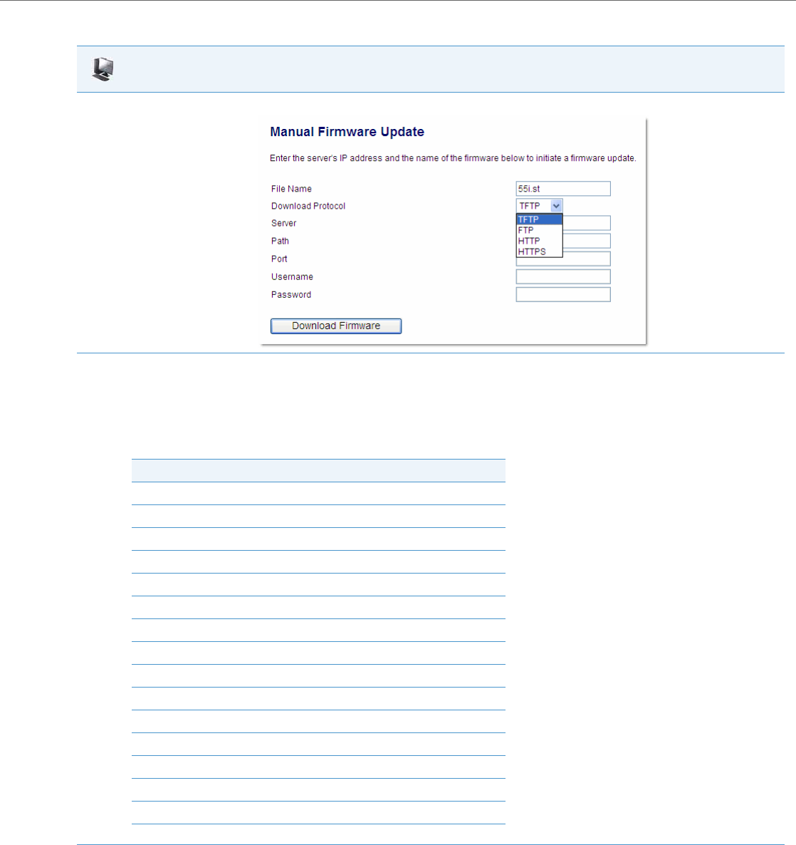
Upgrading the Firmware
41-001343-02 REV04 – 05.2014 8-3
Use the following procedure to manually update the firmware on your phone from the specified configuration server.
Aastra Web UI
1. Click on Advanced Settings->Firmware Update.
2. In the “File Name” field, enter the firmware file name (<phone model>.st) that you want to download to your IP phone. For example, 53i.st (for
a 6753i phone).
Note:
This file name must match the actual name of the firmware file residing on your configuration server.
IMPORTANT: The phones use the following naming convention for the .st files. See the following table.
3. In the “Download Protocol” field, select the protocol from the list to use for downloading the new firmware. Valid values are:
•TFTP
•FTP
•HTTP
•HTTPS
IP Phone Model Associated Firmware
9143i 9143i.st
9480i 9480i.st
9480i CT 9480iCT.st
6730i 6730i.st
6731i 6731i.st
6735i 6735i.st
6737i 6737i.st
6739i 6739i.st
6753i 53i.st
6755i 55i.st
6757i 57i.st
6757i CT 57iCT.st
6863i 6863i.st
6865i 6865i.st
6867i 6867i.st
Upgrading the Firmware
8-4 41-001343-02 REV04 – 05.2014
Using the Restart Feature
Restarting the phone forces the phone to check for both firmware and configuration files stored on the configuration
server.
Restarting the Phone Using the IP Phone UI
4. In the “Server” field, enter the IP address in dotted decimal format, of the TFTP configuration server, or the domain name of the FTP, HTTP,
or HTTPS configuration servers (dependant on the protocol you selected in step 3.) For example: 432.221.45.6.
5. In the “Path” field, enter the path location on the protocol server for where the new firmware resides. For example, C:\aastra\config-
server\firmwareupgrade.
6. In the “Port” field, enter the port number of the protocol server. For example, 80 (for HTTP) or 443 (for HTTPS).
Note:
This field is not applicable to the TFTP and FTP protocols.
7. (FTP only) In the “Username” field, enter the username that is used for authentication when the FTP server is accessed.
8. (FTP only) In the “Password” field, enter the password that is used for authentication when the FTP server is accessed.
9. Click Download Firmware.
This starts the upgrade process. If the upgrade is successful the following message displays on the screen: "Firmware Upgrade Successful".
Warning!
Do not reset or turn off the phone until the download is complete.
IP Phone UI
1. Press on the phone to enter the Options List.
2. Select Restart Phone.
3. For 3-Line LCD Displays:
Press # to confirm.
Note:
To cancel the Restart, press the 3 key.
For 8 and 11-Line LCD Displays:
Press Restart.
Note:
To cancel the Restart, press Cancel.
For the 6739i:
1. Press on the phone to enter the Options List.
2. Press Restart. The following prompt displays:
“Restart the phone?”
3. Press <Yes> to restart the phone
or
Press <No> to go back to the Options Screen.
For the 6867i:
1. Press on the phone to enter the Options List.
Aastra Web UI
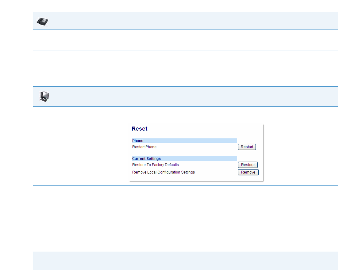
Upgrading the Firmware
41-001343-02 REV04 – 05.2014 8-5
Restarting the Phone Using the Aastra Web UI
Using the Auto-Resync Feature
The auto-resync feature on the IP phones allows an administrator to enable the phone to be updated automatically once a
day at a specific time in a 24-hour period if the files on the server have changed. This feature works with TFTP, FTP, HTTP,
and HTTPS servers. An administrator can enable this feature using the Aastra Web UI or using the configuration files (aas-
tra.cfg, <model>.cfg, and <mac>.cfg).
An Administrator can enable Auto-Resync using the configuration files or the Aastra Web UI. In the configuration files you
set the following parameters:
•auto resync mode - Determines whether the configuration server automatically updates the phone’s configuration
files only, the firmware only, both the firmware and configuration files, or disables automatic updates. This parameter
works with TFTP, FTP, HTTP, and HTTPS servers.
•auto resync time - Sets the time of day in a 24-hour period for the IP phone to be automatically updated. This parame-
ter works with TFTP, FTP, HTTP and HTTPS servers.
•auto resync max delay - Specifies the maximum time, in minutes, the phone waits past the scheduled time before
starting a checksync.
•auto resync days - Specifies the amount of days that the phone waits between checksync operations.
2. Select Restart. The following prompt displays:
“Restart phone?”
3. Select Ye s or press the Restart softkey to restart the phone
or
Select No or press the Cancel softkey to go back to the Options Screen.
Aastra Web UI
1. Click on Operation->Reset->Phone.
2. Click Restart to restart the phone.
Note:
The automatic update feature works with both encrypted and plain text configuration files.
IP Phone UI

Upgrading the Firmware
8-6 41-001343-02 REV04 – 05.2014
In the Aastra Web UI, you can set the following parameters at the path Advanced Settings->Configuration Server->Auto-
Resync:
•Mode
•Time (24 hours)
•Maximum Delay
•Days
Setting the “auto resync max delay” (Maximum Delay) and “auto resync days” (Days) parameters can greatly reduce the
load placed on the configuration server when downloading configurations.
Reloading of Directory Files and Background Image During an Auto-Resync
During an auto-resync, the IP phones have the ability to initiate a comparison of its local directory files with those
located on the configuration server and automatically update the local directory files if changes are detected. For the
6739i, the background image is redownloaded and updated at this time as well.
If the auto-resync mode is set to” Configuration Files (1)” or “Both (3)”, either through the IP phone’s Web UI or configura-
tion files, when the phone reaches the configured auto-resync date/time, the phone will perform a comparison on the
directory files and trigger a reboot if differences are found. For the 6739i, in addition to the directory file comparison, the
background image will be redownloaded and updated. No reboot is necessary if the background image is the only file
that has changed.
If the auto-resync mode is set to “None (0)” or “Firmware Info (2)” and the phone reaches the configured auto-resync
date/time, the directory files will not be checked (and the background image for the 6739i will not be redown-
loaded/updated) .
Enabling Auto-Resync Using the Configuration Files
Use the following procedure to configure automatic updates of the IP phone firmware, configuration files, or both.
Note:
Irrespective of the auto-resync feature, if the phone receives a check-sync NOTIFY, the directory file comparison (and
background image update for the 6739i) will be performed and the applicable files will be automatically updated as
required.
Configuration Files
For specific parameters you can set in the configuration files for automatic update, see Appendix A, the section, “Configuration Server Settings” on
pageA-16.
Notes:
•If a user is accessing the Aastra Web UI, they are not informed of an auto-reboot.
•Any changes made using the Aastra Web UI or the IP phone UI are not overwritten by an auto-resync update. Auto-
resync affects the configuration files only. However, the settings in the Aastra Web UI take precedence over the IP
phone UI and the configuration files.
•If the IP phone is in use (not idle) at the time of the resync check, the reboot occurs when the phone becomes idle.
•The resync time is based on the local time of the IP phone.
•The automatic update feature works with both encrypted and plain text configuration files.
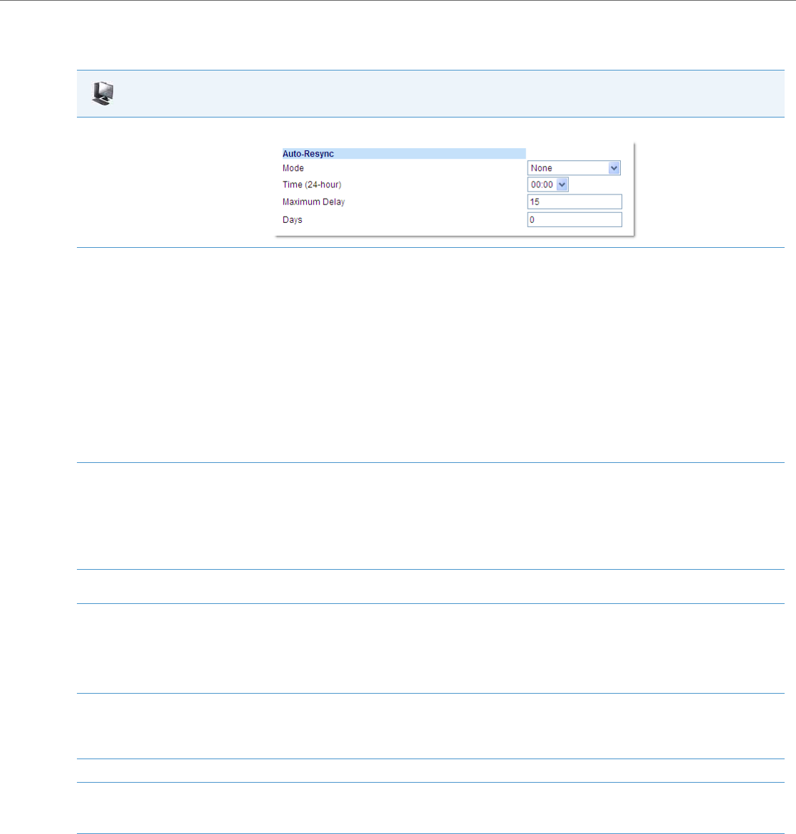
Upgrading the Firmware
41-001343-02 REV04 – 05.2014 8-7
Enabling Auto-Resync Using the Aastra Web UI
Use the following procedure to enable auto-resync for the phones in your network.
Aastra Web UI
1. Click on Advanced Settings->Configuration Server->Auto-Resync.
2. In the “Mode” field, select the auto-resync mode you want to use to automatically update the phone.
Valid values are:
•None Disable auto-resync
•Configuration Files Updates the configuration files on the IP phone automatically at the specified time if the files on the server have
changed.
•Firmware Updates the firmware on the IP phone automatically at the specified time if the files on the server have changed.
•Both Updates the configuration files and firmware automatically at the specified time if the files on the server have changed.
Notes:
•If a user is accessing the Aastra Web UI, they are not informed of an auto-reboot.
•Any changes made using the Aastra Web UI or the IP phone UI are not overwritten by an auto-resync update. Auto-resync affects the con-
figuration files only. However, the settings in the Aastra Web UI take precedence over the IP phone UI and the configuration files.
•The resync time is based on the local time of the IP phone.
•If the IP phone is in use (not idle) at the time of the resync check, the reboot occurs when the phone becomes idle.
3. In the “Time (24-hour)” field, select the time that you want the update to take place.
Valid values are 00:00 to 23:30 (in 30 minute increments).
Notes:
•The resync time is based on the local time of the IP phone.
•The value of 00:00 is 12:00 A.M.
•When selecting a value for this parameter in the Aastra Web UI, the values are in 30-minute increments only.
4. In the “Maximum Delay” field, specify the maximum time, in minutes, the phone waits past the scheduled time before starting a checksync.
The range is 0 to 1439. Default is 15.
5. In the “Days” field, specify the amount of days that the phone waits between checksync operations.
The range is 0 to 364. Default is 0.
Note:
A value of 0 causes the phone to checksync every time the clock reads the proper time. A value of 1 forces the phone to wait 24 hours prior
to doing the first checksync.
6. Click Save Settings to save your settings.
These changes are not dynamic.
You must restart your IP phone for the changes to take affect.
7. Click on Operation->Reset.
8. In the "Restart Phone" field click Restart to restart the IP phone and apply the update.
The update performs automatically at the time you designated.

9-1 41-001343-02 REV04 – 05.2014
Chapter 9
Troubleshooting
About this Chapter
This chapter describes tasks that a system administrator can perform on the IP phones for troubleshooting purposes. It
also includes answers to questions you may have while using the IP phones.
Topics
This chapter covers the following topics:
Topic Page
Troubleshooting page9-2
Log Settings page9-2
Module/Debug Level Settings page9-2
Support Information page9-4
WatchDog Task Feature page9-6
Error Messages Display page9-8
Warning Message Display page9-9
Configuration and Crash File Retrieval page9-9
Troubleshooting Solutions page9-12
Why does my phone display “Application missing”? page9-12
Why does my phone display the “No Service” message? page9-12
Why does my phone display "Bad Encrypted Config"? page9-13
Why is my phone not receiving the TFTP IP address from the DHCP Server? page9-13
How do I restart the IP phone? page9-14
How do I set the IP phone to factory default? page9-15
How do I erase the phone’s local configuration? page9-16
How to reset a user’s password? page9-17
How do I lock and unlock the phone? page9-19

Troubleshooting
41-001343-02 REV04 – 05.2014 9-2
Troubleshooting
This section describes tasks that a system administrator can perform on the IP phones for troubleshooting purposes. Using
the Aastra Web UI, a system administrator can:
•Assign an IP address and IP port to which log information will be transmitted
•Filter the logs according to severity
•Save the current local configuration file to a specified location
•Save the current server configuration file to a specified location
•Show task and stack status (including “Free Memory” and “Maximum Memory Block Size”)
Aastra Technical Support can then use the information gathered to perform troubleshooting tasks.
Log Settings
Using the configuration files or the Aastra Web UI, you can specify the location where log information will be stored for
troubleshooting purposes.
In the configuration files, you use the following parameters to configure log settings:
•log server ip - The IP address of the log server to which log information will be transmitted.
•log server port - The IP port of the log server.
In the Aastra Web UI, you use the following parameters to configure log settings:
•Log IP -The IP address of the log server to which log information will be transmitted
•Log Port - The IP port of the log server.
References
For more information about the log setting configuration parameters, see Appendix A, the section, “Troubleshooting
Parameters” on page A-221.
For information about configuring the log settings using the Aastra Web UI, see “Performing Troubleshooting Tasks” on
page9-5.
Module/Debug Level Settings
The Aastra IP phones provide blog module support that allows enhanced severity filtering of log calls sent as blog output.
The blog, as used on the IP phones, is a an online debugging tool that can be frequently updated and intended for techni-
cal support analysis. Blogs are defined by their format: a series of entries posted to a single page in reverse-chronological
order. The IP Phone blogs are separated into modules which allow you to log specific information for analyzing.
The following table identifies the blog modules you can set.
Aastra Web UI Parameters Configuration File Parameters
LINMGR (Line Manager information) log module linemgr
UI (User Interface (UI) related) log module user interface
MISC (Miscellaneous) log module misc
SIP (Call control SIP stack) log module sip
DIS (Display drivers) log module dis
DSTORE (Delayed storage) log module dstore
EPT (Endpoint module) log module ept
IND (Indicator module) log module ind

Troubleshooting
9-3 41-001343-02 REV04 – 05.2014
Setting Values for the Module/Debug Levels
There are 6 debug levels for the modules. Each debug level has a value you can use to turn individual levels ON and OFF.
The following table identifies these debug levels and their values. The value of “1” (fatal errors) is the default setting for
all modules.
Example 1
To turn two or more debug levels on at the same time, you add the value associated with each level. For example,
Fatal Errors + Errors + Warnings = 1 + 2 + 4 = 7
log module linemgr: 7
log module user interface: 7
log module sip: 7
In the above example, fatal errors, general errors, and warnings are logged for the line manager, user interface, and SIP
call control modules.
Example 2
Functions and Info = 16 + 32 = 48
log module dis: 48
log module net: 48
log module snd: 48
In the above example, functions and general information are logged for the display drivers, network, and sound mod-
ules.
KBD (Keyboard module) log module kbd
NET (Network module) log module net
PROVIS (Provisioning module) log module provis
RTPT (Realtime Transport module) log module rtpt
SND (Sound module) log module snd
PROF (Profiler module) log module prof
XML (Extension Markup Language) log module xml
STUN (Simple Traversal of User Datagram Protocol (UDP) through Network
Address Translation (NAT) log module stun
LLDP (Link Layer Discovery Protocol) log module lldp
BLUETOOTH (6739i only) log module bluetooth
Debug Level Value
Fatal Errors 1 (default)
Errors 2
Warnings 4
Init 8
Functions 16
Info 32
All debug levels OFF 0
All Debug Levels ON 65535
Aastra Web UI Parameters Configuration File Parameters
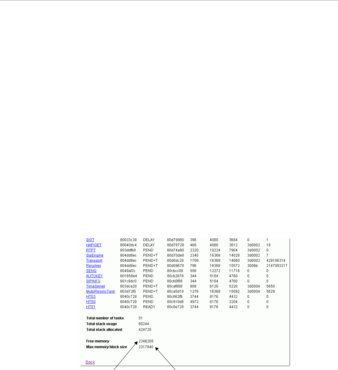
Troubleshooting
41-001343-02 REV04 – 05.2014 9-4
Example 3
log module rtpt: 0
log module ind: 65535
In the above example, all debug levels are OFF for the Real Time Transport module. All debug levels are ON for the indica-
tor module.
You can set the Module/Debug Levels using the configuration files or the Aastra Web UI.
References
For more information about the debug level configuration parameters, see Appendix A, the section, “Troubleshooting
Parameters” on page A-221.
For information about configuring the log settings using the Aastra Web UI, see “Performing Troubleshooting Tasks” on
page9-5.
Support Information
You can save the local and/or server configuration files of the IP phone to the location specified in the "Log Settings" sec-
tion.
Performing this task allows Aastra Technical Support to view the current configuration of the IP phone and troubleshoot
as necessary.
In the “Support Information” section, you can:
•Get local.cfg
•Get server.cfg
•Show Task and Stack Status
Aastra Technical Support uses this support information for troubleshooting the IP phone when required.
Using the Aastra Web UI and selecting “Show Task and Stack Status” displays the tasks and stack status on the IP phone.
This screen also displays the Free Memory and the Max Block Free Memory currently on the phone as shown in the fol-
lowing illustration. This information is for troubleshooting purposes only.
Free Memory Max Memory Block Size
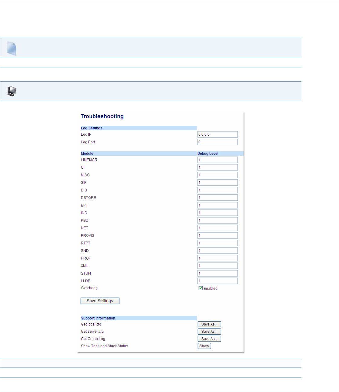
Troubleshooting
9-5 41-001343-02 REV04 – 05.2014
Performing Troubleshooting Tasks
Use the following procedures to perform troubleshooting on the IP phone via the configuration files or the Aastra Web
UI.
Configuration Files
For specific parameters you can set in the configuration files, see Appendix A, the section, “Log Settings” on pageA-221.
Aastra Web UI
1. Click on Advanced Settings->Troubleshooting.
To set log settings:
2. In the "Log IP" field, enter the IP address of the log server (i.e. the server to which log information will be transmitted).
3. In the "Log Port" field, enter the port number associated with the IP address specified in the "Log IP" field. This port passes the information
from the IP phone to the IP address location.
4. Click Save Settings to save your settings.

Troubleshooting
41-001343-02 REV04 – 05.2014 9-6
Reference
For information that describes solutions to most common problems using the IP phones, see the next section, “Trouble-
shooting Solutions” on page9-12.
WatchDog Task Feature
The IP Phones include a troubleshooting feature called the “WatchDog” that monitors the status of the phone’s tasks and
provides the ability to get stack traces from the last time the phone failed. When the phone detects a failure (i.e., a crash), it
automatically reboots. You can view a WatchDog crash file using the Aastra Web UI at the path, Advanced Settings->Trou-
bleshooting. You can enable/disable the WatchDog task using the configuration files or the Aastra Web UI.
5. Click on Operation->Reset.
6. In the "Restart Phone" field click Restart to restart the IP phone.
To set blog modules:
7. Select the applicable module.
8. Enter a debug level value in the “Debug Level” field for a module. Valid values are:
The value of “0” turns all debug levels OFF for a module. The value of “65535” turns all debug levels ON for a module.
To turn two or more debug levels on at the same time, you add the value associated with each level. For example, Fatal Errors + Errors + Warn-
ings = 1 + 2 + 4 = 7
log module linemgr: 7
log module user interface: 7
log module sip: 7
In the above example, fatal errors, general errors, and warnings are logged for the line manager, user interface, and SIP call control modules.
9. Click Save Settings to save your settings.
10. Click on Operation->Reset.
11. In the "Restart Phone" field click Restart to restart the IP phone.
To perform support tasks:
12. To store the local configuration file to the specified location, click on Save As in the "Get local.cfg" field.
13. To store the server configuration file to the specified location, click on Save As in the "Get server.cfg" field.
14. To display task and stack status information, as well as Free Memory and Maximum Block Free Memory on the phone, click on Show in the
"Show Task and Stack Status" field.
Note:
The local and server configuration file information and the task and stack status information is for use by Aastra Technical Support for trou-
bleshooting purposes.
Aastra Web UI
Debug Level Value
Fatal Errors 1 (default)
Errors 2
Warnings 4
Init 8
Functions 16
Info 32
All debug levels OFF 0
All Debug Levels ON 65535
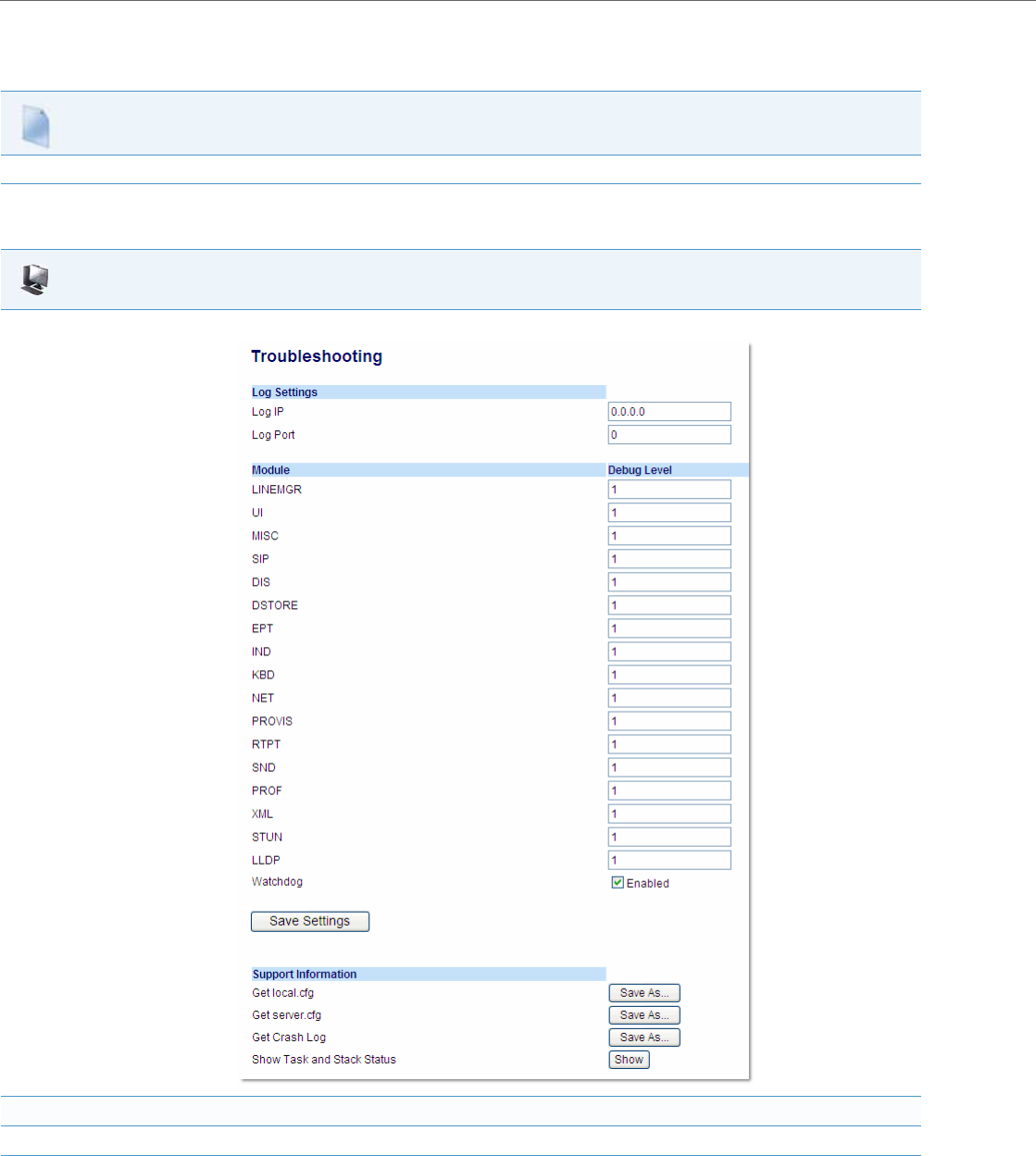
Troubleshooting
9-7 41-001343-02 REV04 – 05.2014
Enabling/Disabling WatchDog
Use the following procedure to enable/disable the WatchDog.
Use the following procedure to enable/disable the WatchDog task for the IP Phones using the Aastra Web UI. You can
also view the “Crash Log” generated by the WatchDog task using the Aastra Web UI.
Configuration Files
For specific parameters you can set in the configuration files, see Appendix A, the section, “WatchDog Settings” on pageA-224.
Aastra Web UI
1. Click on Advanced Settings->Troubleshooting.
Enable/Disable WatchDog Task
2. The “WatchDog” field is enabled by default. To disable the WatchDog task, click in the “Enabled” box to clear the check mark.
3. Click Save Settings to save your changes.

Troubleshooting
41-001343-02 REV04 – 05.2014 9-8
Error Messages Display
An Administrator can view generated error messages that may have occurred during startup or reboot of the IP Phones.
The IP Phone UI has a selection on the Phone Status page called, “Error Messages” at the location, Options->Phone Status-
>Error Messages. The Aastra Web UI also allows you to view these error messages at the location Advanced Settings->Trou-
bleshooting->Error Messages. These options allow you to view error messages generated by modules during startup only
(not after registration has completed). You can use this information for troubleshooting purposes or for reporting the
errors to the Administrator.
The IP Phone stores and displays up to 10 error messages (any extra error messages beyond 10 are discarded). The time
and date of each error message also displays. After a reboot, the previous error messages are discarded and, if applicable,
new error messages display. If there are no error messages during startup or after a reboot, the message, “No Error Mes-
sages” displays on the screen. Error messages display in the language currently set on the phone.
The following table identifies the possible error messages that may display.
Viewing the Error Messages Using the IP Phone UI
Use the following procedure to view the error messages, if any, that generated during startup.
View the Crash Log
4. To view a crash log, in the “Get a Crash Log” field, click the SAVE AS button. You can open the file immediately, or you can save the Crash
Log to your PC.
Possible Error Message Description
Bad Certificate A Transport Layer Security (TLS) certificate is not valid. The invalid certifi-
cate can be any of the following:
•root and intermediate certificate
•local certificate
•private key filename
•trusted certificate
802.1x Startup Failed The Extensible Authentication Protocol TLS (EAP-TLS) certificates and/or
the EAP-MD5 information has failed on the phone.
LLDP Startup Failed Link Layer Discovery Protocol (LLDP) failed during startup of the phone.
HTTP Connection Manager Init Failed The Hypertext Transfer Protocol (HTTP) connection manager initialization
failed while updating the configuration on the phone.
Failed to Config Line Manager The configuration of the Line Manager module on the phone has failed.
IP Phone UI
1. Press the Options key on the phone to enter the Options List.
2. Select Phone Status.
3. Select Error Messages.
4. If error messages display, use the UP and DOWN navigation keys to view the messages. If no error message exist, the message, “No Error Mes-
sages” displays on the screen.
5. When done viewing, press Done or Exit to exit the Error Messages screen.
Aastra Web UI
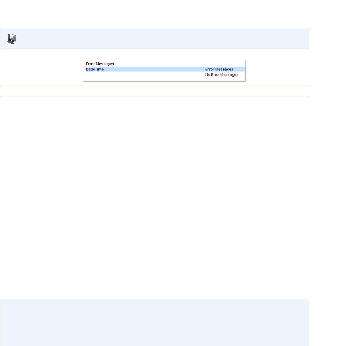
Troubleshooting
9-9 41-001343-02 REV04 – 05.2014
Viewing the Error Messages Using the Aastra Web UI
Use the following procedure to view the error messages, if any, that generated during startup.
Warning Message Display
Previously when a phone fails to download from the first configuration server as listed in the Fully Qualified Domain
Name (FQDN) server list, it attempts to download from the other servers from the list. If the phone successfully down-
loads from the alternate server, it would display an Error message on the idle screen. This Error message is now classified
as a Warning message and is not displayed to the end user on the idle screen.
Administrators will see the warning message along with other error messages in the Web UI (Advanced Settings ->
Troubleshooting -> Error Messages) or on the Phone UI (Options Key -> Phone Status -> Error Messages).
Configuration and Crash File Retrieval
In addition to using the Troubleshooting page in the Aastra Web UI, an Administrator can also use three new configura-
tion parameters in the configuration files to enable/disable the uploading of support information to a pre-defined
server. These parameters are:
•upload system info server - Specifies the server for which the phone sends the system and crash files.
•upload system info manual option - Enables and disables the ability to manually upload support information from
the IP Phone UI and Aastra Web UI.
•upload system info on crash - Enables and disables the watchdog to automatically reboot the phone and send a
crash file to the pre-defined server.
When this feature is enabled (configuration files only), support files can be automatically or manually generated and
uploaded when the server detects a phone failure. An Administrator or User can manually send the files when required
using the IP Phone UI or the Aastra Web UI. Each time the files are generated and uploaded, a new timestamp on the file
name is created so that existing files are not overwritten on the server. File names are generated in the format
MAC ID_Date_Time_server.cfg, MAC ID_Date_Time_local.cfg, and MAC ID_Date_Time_crash.cfg
Aastra Web UI
1. Click on Advanced Settings->Troubleshooting->Error Messages.
2. Scroll down to the “Error Messages” section to view the error messages that may have generated during startup or reboot of the IP Phone.
Notes:
•The phone performs the generation and sending of Support Information in the background. This feature does not
affect the use or operation of the phone.
•During a startup or reboot of the phone, an upload of Support Information is automatically generated and sent to
the pre-defined server.
•This feature supports the TFTP, FTP, HTTP, and HTTPS protocols.
Troubleshooting
41-001343-02 REV04 – 05.2014 9-10
The following table identifies the methods you can use to retrieve support information from the phone to the pre-defined
server when the above configuration parameters are enabled.
When this feature is enabled, the phone sends the following support information files to the server:
•Server.cfg - File in the format MAC ID_Date_Time_server.cfg that contains configuration information from the aas-
tra.cfg, the <model>.cfg, and the <mac>.cfg files. The MAC address, date, and time are specified in the file name to
identify the phone sending the information, and the date and time the file was generated and sent to the server.
(for example, 00093D435522_2010-02-25_1141am_server.cfg)
•Local.cfg - File in the format MAC ID_Date_Time_local.cfg that contains information of locally modified values made
using the Aastra Web UI and/or the IP Phone UI. The MAC address, date, and time are specified in the file name to iden-
tify the phone sending the information, and the date and time the file was generated and sent to the server.
(for example, 00043D199345_2010-02-26_1030am_local.cfg)
•Crash.cfg - (only generated if an error or crash occurs on the phone) File in the format MAC ID_Date_Time_crash.cfg
that contains information about a current phone error/crash causing a reboot of the phone . The MAC address, date,
and time are specified in the file name to identify the phone sending the information, and the date and time the file was
generated and sent to the server.
(for example, 00033D000111_2010-02-27_0204pm_crash.cfg)
Configuring Crash File Retrieval Using the Configuration Files
Use the following procedure to configure crash file retrieval from the phone to a server.
Generating and Sending Support Information from the IP Phone UI
Use the following procedure to generate and send Support Information files to the server.
Method for Retrieving
Support Info Description
Configuration Files (automatic
retrieval) 1. Enter “upload system info server” parameter in the configuration files and specify the server for which the
phone sends the system crash information
2. Enter “upload system info on crash: 1” to enable the phone to automatically send system crash information
to the pre-defined server each time the watchdog reboots.
IP Phone UI
(manual retrieval)
1. On the phone, navigate to Options->Phone Status->Upload System Info.
2. Press “Select” or “Enter”. The system information is immediately sent to the pre-defined server and the mes-
sage “Files Sent” displays.
Aastra Web UI
(manual retrieval)
1. On the Aastra Web UI, navigate to Status->System Information->Support Information.
2. Press <Upload>. The system information is immediately sent to the pre-defined server and the message
“Files Sent” displays.
Configuration Files
For specific parameters you can set in the configuration files, see Appendix A, the section, “Crash File Retrieval” on pageA-224.
IP Phone UI
For 8 and 11-Line Phones:
1. Press on the phone to enter the Options List.
2. Select Phone Status.
3. Select Upload System Info and press <Select>. The phone immediately generates the applicable Support Information files (server.cfg,
local. cfg, and/or crash.cfg) and sends the files to the pre-defined server. The message “Files Sent” displays.
For 3-Line Phones:
1. Press on the phone to enter the Options List.
2. Select Phone Status.
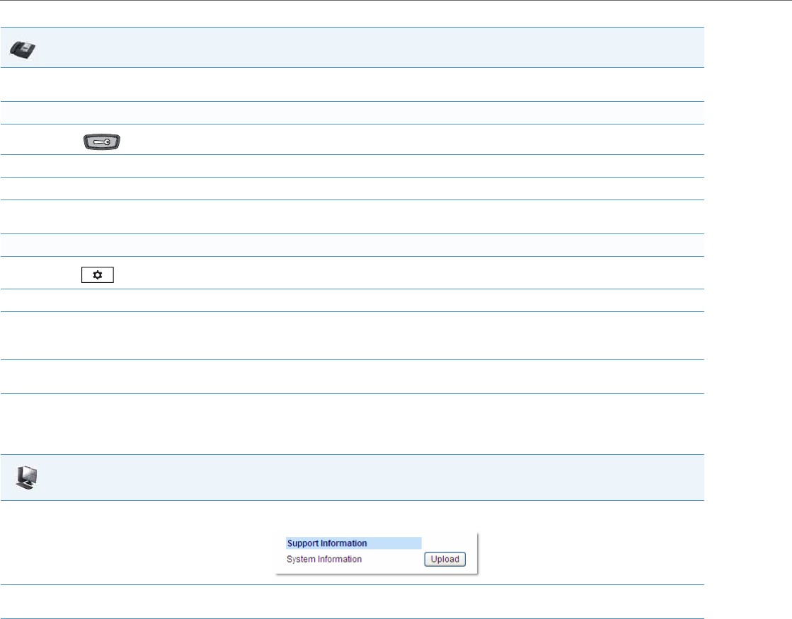
Troubleshooting
9-11 41-001343-02 REV04 – 05.2014
Generating and Sending Support Information from the Aastra Web UI
Use the following procedure to generate and send Support Information files to the server.
Limitations
•If sending the Support Information files to a folder on the server, then writing privileges must be allowed for that
folder.
•If the Administrator password and username are configured in the Server.cfg file, a User can retrieve that information
after the Server.cfg file is loaded to the server.
•TFTP does not report transmission failure if the destination server is down. In this case, the Support Information files
are not sent.
3. Select Upload System Info and press <Enter>. The phone immediately generates the applicable Support Information files (server.cfg, local.
cfg, and/or crash.cfg) and sends the files to the pre-defined server. The message “Files Sent” displays.
For the 6739i:
1. Press on the phone to enter the Options List.
2. Select Status.
3. Press Upload.
4. Press Upload Sys Info. The phone immediately generates the applicable Support Information files (server.cfg, local. cfg, and/or crash.cfg)
and sends the files to the pre-defined server. The message “Files Sent” displays.
For the 6867i:
1. Press on the phone to enter the Options List.
2. Select Status.
3. Press the Sys Info softkey. The following prompt displays:
“Upload System Info Files?”
4. Select Ye s or press the Upload softkey. The phone immediately generates the applicable Support Information files (server.cfg, local. cfg,
and/or crash.cfg) and sends the files to the pre-defined server. The message “Files Sent” displays.
Aastra Web UI
1. Click on Status->System Information-> Support Information.
2. Press <Upload>. The phone immediately generates the applicable Support Information files (server.cfg, local. cfg, and/or crash.cfg) and
sends the files to the pre-defined server. The message “Files Sent” displays.
IP Phone UI

Troubleshooting Solutions
41-001343-02 REV04 – 05.2014 9-12
Troubleshooting Solutions
Description
This section describes solutions to some most common problems that can occur while using the IP phones.
Why does my phone display “Application missing”?
If you have experienced networking issues while the phone was downloading the application from the TFTP server, it is
possible that the phone can no longer retrieve the required firmware file. In the event that the phone is no longer able to
communicate with the TFTP server in its attempt to re-download the firmware and the phone cannot locate the applica-
tion locally, the message "Application missing" displays.
The phone also displays the following: “Recovery web-client at: <IP Address>”. The IP Address displayed is the IP address of
the phone. If the phone is unable to receive an IP from the DHCP server or has lost its record of its static IP, the phone auto-
assigns itself the default IP 192.168.0.50.
To recover the firmware for your phone in this circumstance, please perform the following:
Please ensure that the TFTP server is running and accessible on the network. If the firmware file is correctly located on the
running TFTP server, the phone will locate the file and reload the application onto the phone.
Why does my phone display the “No Service” message?
The phone displays the “No Service” message if it is not able to successfully register with the Registrar. If the Registrar is up
and running the SIP settings may not have not been set up correctly.
The Registrar server could be set to 0.0.0.0. A global value of 0.0.0.0 disables registration. However, the phone is still active
and you can dial using username@ip address of the phone. The phone displays "No Service".
If the Registrar IP address is set to 0.0.0.0 for a per-line basis (i.e., line 1, line 2, etc.), then the register request is not sent, the
"No Service" message does not display, and the message waiting indicator (MWI) does not come on.
Check that the "Registrar Server" IP address in the Aastra Web UI at Advanced Settings->Global SIP is correct. Check the
"sip registrar ip" parameter in the configuration files is correct.
1. Launch your web browser on your computer.
Note:
Your computer needs to be on the same network as your IP Phone.
2. In the URL, type: “http://<IP Address>” (where IP Address is the IP Address displayed on the phone). Your browser launches the
Aastra IP Phone Firmware Recovery page.
3. Call Customer Support and request a <phone model>.st file.
4. Copy the file to your TFTP server.
5. Enter the <phone model>.st file that is ready for download.
6. Enter the IP address or qualified domain name of the TFTP server.
7. Press the Download Firmware button.

Troubleshooting Solutions
9-13 41-001343-02 REV04 – 05.2014
Why does my phone display "Bad Encrypted Config"?
The IP phone displays "Bad Encrypted Config" because encrypted configuration files are enabled but the decryption
process has failed. Specific cases where decryption fails are:
Reason
The site-specific password in security.tuz does not match the password used to encrypt the <mac>.tuz or aastra.tuz files.
Fix
Encrypt the .cfg files to .tuz using the correct password, or replace the security.tuz with the correct encrypted file.
Reason
Neither of the <mac>.tuz and aastra.tuz files are present on the configuration server (TFTP/FTP/HTTP).
Fix
Create the encrypted files using anacrypt.exe and copy them to the configuration server.
Reason
The encrypted <mac>.tuz or aastra.tuz file is encrypted using a different version of anacrypt.exe than the phone
firmware.
Fix
Run "anacrypt.exe -v" and confirm that the correct version is reported, compared to the phone firmware version.
Why is my phone not receiving the TFTP IP address from the DHCP Server?
For DHCP to automatically populate the IP address or qualified domain name for the TFTP server, your DHCP server must
support Option 66. Option 66 is responsible for forwarding the TFTP server IP address or domain name to the phone
automatically. If your DHCP server does not support Option 66, you must manually enter the IP address or qualified
domain name for the TFTP server into your IP phone configuration.
Additionally, the phone may not be receiving the TFTP IP address if there are other DHCP servers within the same broad-
cast domain providing different Option 66 (TFTP server) settings. See “DHCP” on page 4-3 for more information on
option precedence.
For procedures on configuring the TFTP server using the IP phone UI and the Aastra Web UI, see Chapter 4, the section,
“Configuring the Configuration Server Protocol” on page4-87.
For specific protocol parameters you can set in the configuration files, see Appendix A, the section, “Configuration Server
Settings” on page A-16.
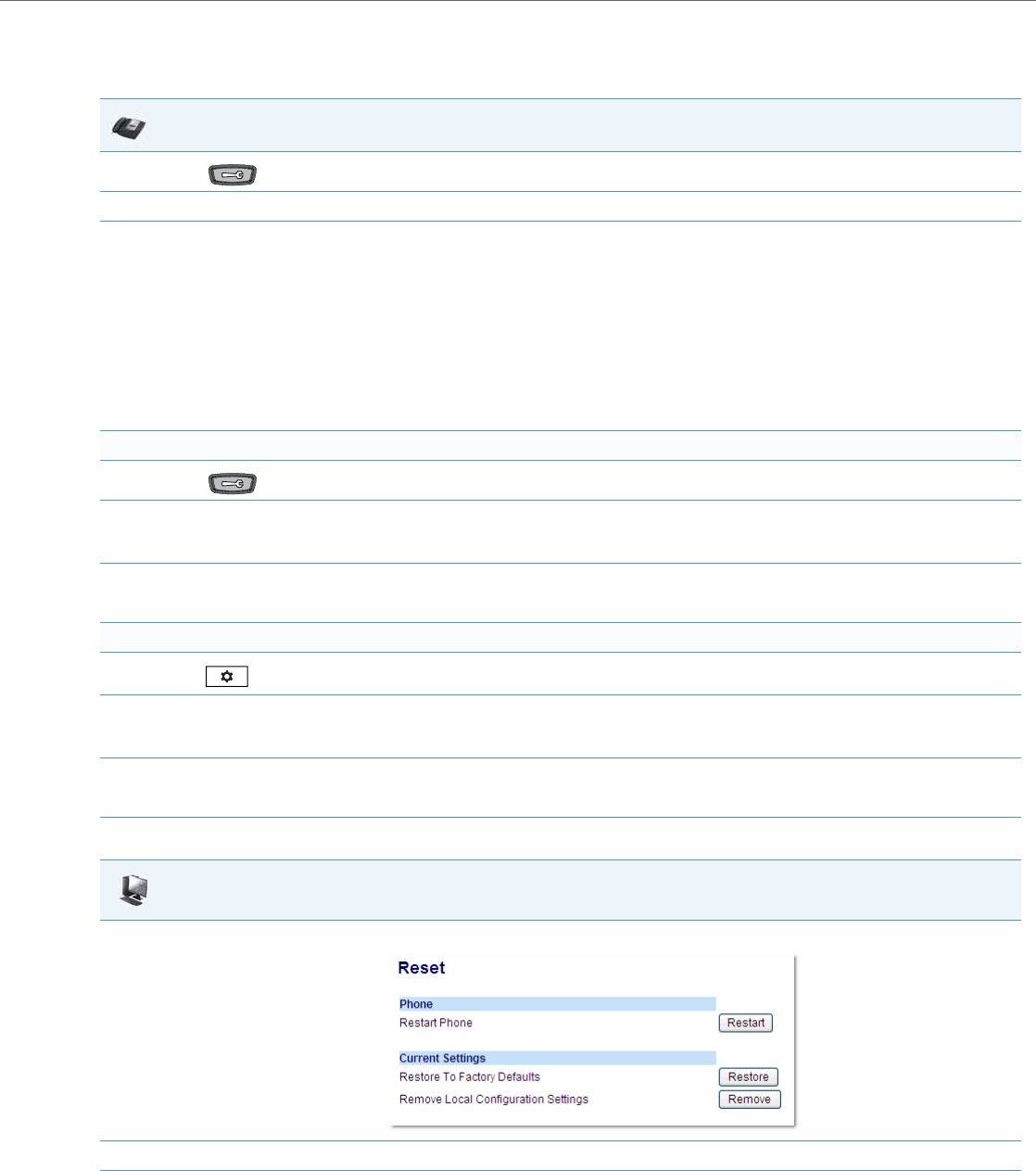
Troubleshooting Solutions
41-001343-02 REV04 – 05.2014 9-14
How do I restart the IP phone?
IP Phone UI
1. Press on the phone to enter the Options List.
2. Select Restart Phone.
3. For 3-Line LCD Displays:
Press # to confirm.
Note:
To cancel the Restart, press the 3 key.
For 8 and 11-Line LCD Displays:
Press Restart.
Note:
To cancel the Restart, press Cancel.
For the 6739i:
1. Press on the phone to enter the Options List.
2. Press Restart. The following prompt displays:
“Restart the phone?”
3. Press <Yes> to restart the phone
or
Press <No> to go back to the Options Screen.
For the 6867i:
1. Press on the phone to enter the Options List.
2. Select Restart. The following prompt displays:
“Restart phone?”
3. Select Ye s or press the Restart softkey to restart the phone
or
Select No or press the Cancel softkey to go back to the Options Screen.
Aastra Web UI
1. Click on Operation->Reset->Phone.
2. Click Restart to restart the phone.
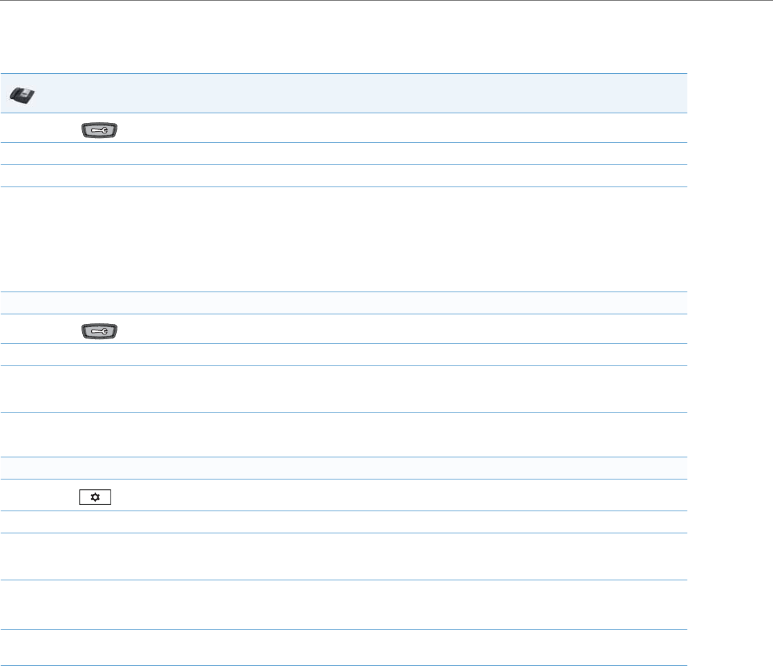
Troubleshooting Solutions
9-15 41-001343-02 REV04 – 05.2014
How do I set the IP phone to factory default?
IP Phone UI
1. Press on the phone to enter the Options List.
2. Select Administrator Menu and enter your Administrator Password (default is 22222).
3. Select Factory Default.
4. For 3-Line LCD Displays:
The “Restore Defaults?” prompt displays.
Press # to confirm.
For 8 and 11-Line LCD Phones
The “Reset phone to factory defaults?” prompt displays.
Press Default to confirm.
For the 6739i:
1. Press on the phone to enter the Options List.
2. Press Advanced and enter your Administrator password using the pop-up keyboard that displays. (Default is 22222).
3. Press Reset.
The “Reset Configuration?” prompt displays.
4. Press Factory Default.
The phone immediately sets the phone to factory defaults and automatically restarts the phone.
For the 6867i:
1. Press on the phone to enter the Options List.
2. Press the Advanced softkey and enter your Administrator password using the keypad keys. (Default is 22222).
3. Select Reset.
The “Reset Configuration?” prompt displays.
4. Select Factory Default.
The “Factory Default?” prompt displays.
5. Select Yes or press the Reset softkey to factory default the phone.
The phone immediately sets the phone to factory defaults and automatically restarts the phone.
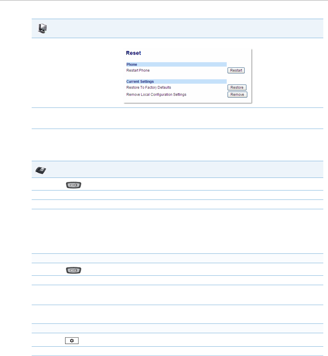
Troubleshooting Solutions
41-001343-02 REV04 – 05.2014 9-16
How do I erase the phone’s local configuration?
Aastra Web UI
1. Click on Operation->Reset->Current Settings.
2. In the "Restore to Factory Defaults" field, click Restore.
This restores all factory defaults, and removes any saved configuration and directory list files.
IP Phone UI
1. Press on the phone to enter the Options List.
2. Select Administrator Menu and enter your Administrator Password (default is 22222).
3. Select Erase Local Config.
4. For 3-Line LCD Displays:
The “Erase local config?” prompt displays.
Press # to confirm.
For 8 and 11-Line LCD Displays:
The “Erase local config?” prompt displays.
Press Erase to confirm.
For the 6739i:
1. Press on the phone to enter the Options List.
2. Press Advanced and enter your Administrator password using the pop-up keyboard that displays. (Default is 22222).
3. Press Reset.
The “Reset Configuration?” prompt displays.
4. Press Erase Local Cfg.
The phone immediately erases the local configuration and automatically restarts the phone.
For the 6867i:
1. Press on the phone to enter the Options List.
2. Press the Advanced softkey and enter your Administrator password using the keypad keys. (Default is 22222).
3. Select Reset.
The “Reset Configuration?” prompt displays.
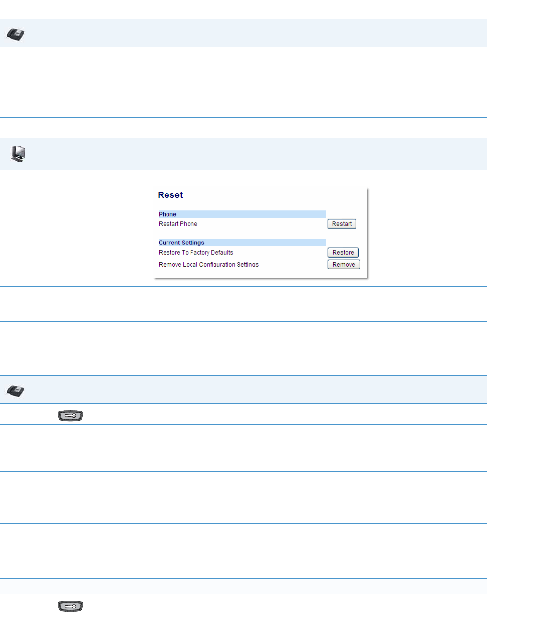
Troubleshooting Solutions
9-17 41-001343-02 REV04 – 05.2014
How to reset a user’s password?
4. Select Erase Local Config.
The “Erase Local Configuration?” prompt displays.
5. Select Yes or press the Reset softkey to erase the local configuration.
The phone immediately erases the local configuration and automatically restarts the phone.
Aastra Web UI
1. Click on Operation->Reset->Current Settings.
2. In the "Remove Local Configuration Settings" field, click Remove.
This removes the last customized configuration settings made on the phone.
IP Phone UI
1. Press on the phone to enter the Options List.
2. Select User Password.
3. Enter the current user password.
4. Press Enter.
5. Enter the new user password.
Note:
The IP phones support numeric characters only in passwords. If you enter a password with alpha characters, the phone uses the default pass-
word instead.
6. Press Enter.
7. Re-enter the new user password.
8. Press Enter.
A message, "Password Changed" displays on the screen.
For the 6739i:
1. Press on the phone to enter the Options List.
2. Press Password.
3. Press the <Current Password> field. A keyboard displays on the screen.
IP Phone UI
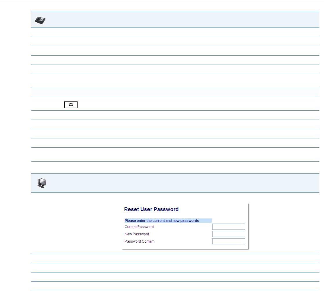
Troubleshooting Solutions
41-001343-02 REV04 – 05.2014 9-18
4. Enter the current user password in the text box and press the <Enter> key on the keyboard.
5. Press the <New Password> field.
6. Enter the new user password in the text box and press the <Enter> key on the keyboard.
7. Press the <Re-enter Password> field.
8. Re-enter the new user password in the text box and press the <Enter> key on the keyboard.
9. Press <Save>.
A message, "Password Changed" displays on the screen.
For the 6867i:
1. Press on the phone to enter the Options List.
2. Select Lock > Password.
3. Enter the current password in the <Current Password> field.
4. Press the down navigation key and enter the new password in the <New Password> field.
5. Press the down navigation key and enter the new password again in the <Re-enter Password> field.
6. Press the Save softkey.
A message, "Password Changed" displays on the screen.
Aastra Web UI
1. Click on Operation->User Password.
2. In the "Current Password" field, enter the current user password.
3. In the "New Password" field, enter the new user password.
4. In the "Confirm Password" field, enter the new user password again.
5. Click Save Settings to save your changes.
IP Phone UI
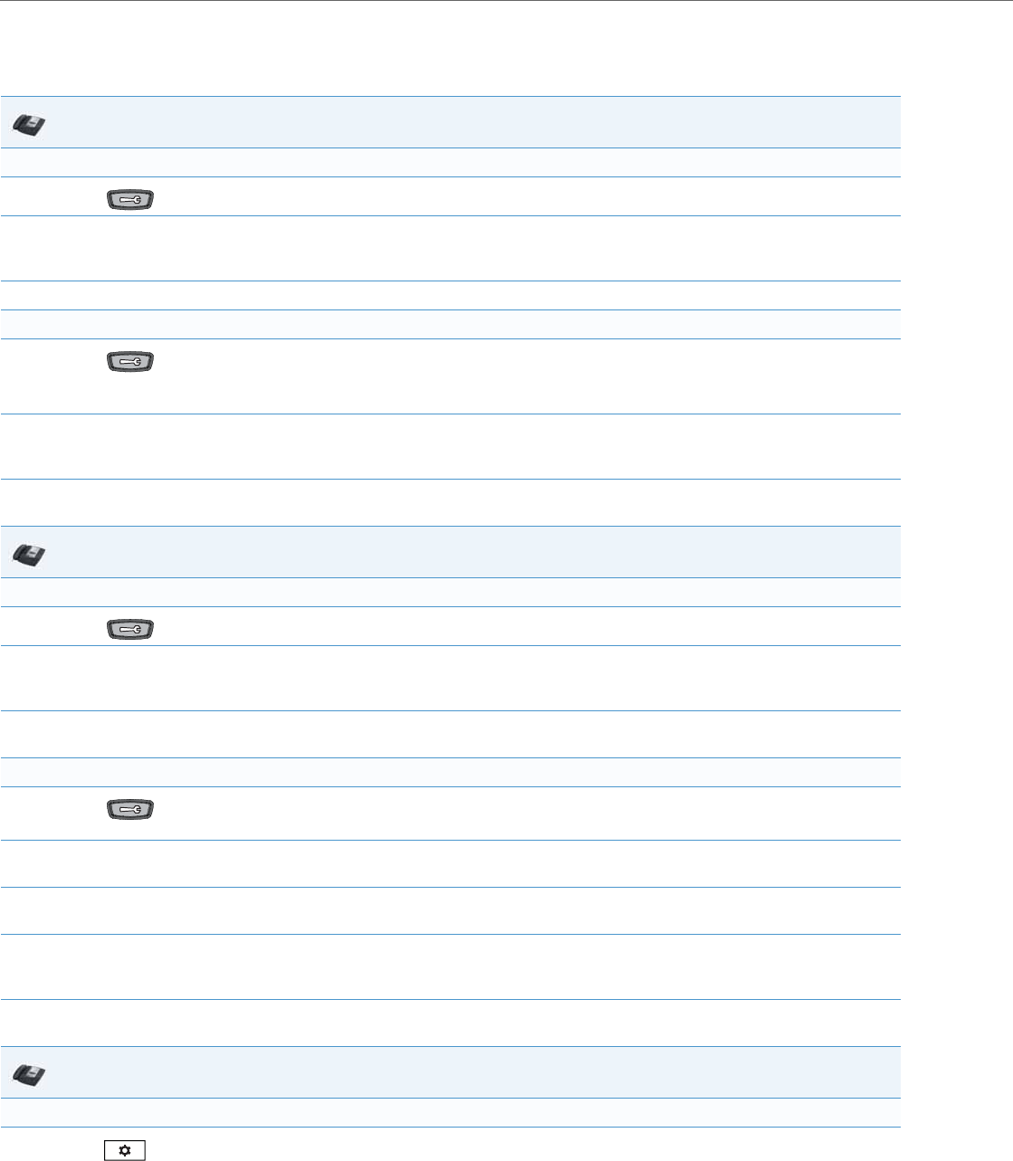
Troubleshooting Solutions
9-19 41-001343-02 REV04 – 05.2014
How do I lock and unlock the phone?
For 6739i:
For 6867i:
IP Phone UI
Lock the phone:
1. Press on the phone to enter the Options List.
2. Select Phone Lock.
The prompt, “Lock the phone?” displays.
3. Press Lock to lock the phone.
Unlock the phone:
1. Press on the phone to enter the Options List.
The prompt, “To unlock the phone...Password:”
2. Enter the user or administrator password and press Enter.
The phone unlocks.
IP Phone UI
Lock the phone:
1. Press on the phone to enter the Options List.
2. Select Lock.
The prompt, “Lock the phone?” displays.
3. Press Ye s to lock the phone.
The phone locks.
Unlock the phone:
1. Press on the phone to enter the Options List.
A “Phone is Locked” screen displays allowing you to press an “Unlock the Phone” button.
2. Press Unlock the Phone.
A prompt, “Enter Unlock Password” displays as well as a keyboard.
3. Enter the user or administrator password and press Enter. Default is “22222”.
A prompt “Unlock the Phone?” displays.
4. Press Ye s to unlock the phone.
The phone unlocks.
IP Phone UI
Lock the phone:
1. Press on the phone to enter the Options List.
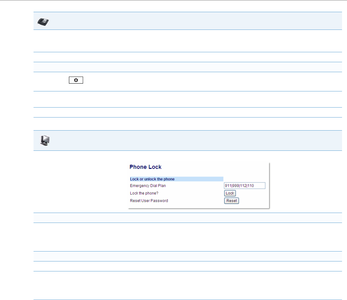
Troubleshooting Solutions
41-001343-02 REV04 – 05.2014 9-20
2. Select Lock > Phone Lock.
The prompt, “Lock the phone?” displays.
3. Select Ye s or press the Lock softkey to lock the phone.
Unlock the phone:
1. Press on the phone to enter the Options List.
An “Enter Unlock Password” prompt displays.
2. Enter the user or administrator password and press Enter. Default is “22222”.
A prompt “Unlock the Phone?” displays.
3. Select Ye s or press the Unlock softkey to unlock the phone.
Aastra Web UI
1. Click on Operation->Phone Lock.
Lock the phone:
2. In the “Lock the Phone?” field, click Lock.
The phone locks dynamically and displays the following message:
“Phone is locked”.
Unlock the phone:
3. Click on Operation->Phone Lock.
4. In the “Unlock the Phone?” field, click Unlock.
The phone unlocks dynamically and displays the following message:
“Phone is unlocked”.
IP Phone UI

A-1 41-001343-02 REV04 – 05.2014
Appendix A
Configuration Parameters
About this Appendix
This appendix describes the parameters you can set in the configuration files for the IP phones. The configuration files
include aastra.cfg, <model>.cfg, and <mac.cfg>.
Topics
This appendix covers the following topics:
Topic Page
Setting Parameters in Configuration Files pageA-6
Operational, Basic, and Advanced Parameters pageA-6
Simplified IP Phone UI Options Menu pageA-7
Network Settings pageA-8
DHCP Option Settings pageA-12
Password Settings pageA-14
Emergency Dial Plan Settings pageA-15
Emergency Call Behavior Settings pageA-15
User Dial Plan Setting pageA-15
Aastra Web UI Settings pageA-16
Configuration Server Settings pageA-16
Multiple Configuration Server Settings pageA-24
Network Address Translation (NAT) Settings pageA-25
Rport Setting pageA-26
Local SIP UDP/TCP Port Setting pageA-26
Local SIP TLS Port pageA-27
SIP STUN Parameters pageA-27
SIP TURN Parameters pageA-28
SIP Keep Alive Support pageA-30
HTTPS Client and Server Settings pageA-30
HTTPS Server Certificate Validation Settings pageA-31
Virtual Local Area Network (VLAN) Settings pageA-34
RTCP Summary Reports pageA-37
Type of Service (ToS)/DSCP Settings pageA-39
Time and Date Settings pageA-40
Time Server Settings pageA-45
Custom Time Zone and DST Settings pageA-47

About this Appendix
41-001343-02 REV04 – 05.2014 A-2
Backlight Mode Settings pageA-53
Brightness Level Settings pageA-54
Background Image on Idle Screen pageA-55
Configurable Home/Idle Screen Modes pageA-55
Picture ID Feature pageA-56
DHSG Settings pageA-56
Bluetooth Support Settings pageA-57
Wideband Audio Equalizer Settings pageA-57
Live Dialpad Settings pageA-58
SIP Local Dial Plan Settings pageA-58
SIP Outbound Support pageA-60
Contact Header Matching pageA-60
SIP Basic, Global Settings pageA-61
Backup Outbound Proxy (Global Settings) pageA-68
SIP Basic, Per-Line Settings pageA-69
Backup Outbound Proxy (Per-line Settings) pageA-77
BLA Support for MWI pageA-77
Shared Call Appearance (SCA) Call Bridging pageA-78
Centralized Conferencing Settings pageA-79
Custom Ad-Hoc Conference pageA-80
SIP Join Feature for 3-Way Conference pageA-80
Conference/Transfer in Live Dial Mode pageA-80
HTTP/HTTPS Authentication Support for Broadsoft CMS pageA-81
Advanced SIP Settings pageA-82
Missed Call Summary Subscription Settings pageA-87
As-Feature-Event Subscription Settings pageA-88
Transport Layer Security (TLS) Settings pageA-89
802.1x Support Settings pageA-94
RTP, Codec, DTMF Global Settings pageA-99
Autodial Settings pageA-104
Voicemail Settings pageA-105
SCA Voicemail Indicator Settings pageA-106
Directory Settings pageA-107
Customizable Directory List Key pageA-109
Callers List Settings pageA-109
Customizable Callers List and Services Key pageA-110
Call Forward Settings pageA-110
Call Forward Key Mode Settings pageA-111
PIN Suppression pageA-112
Topic Page

About this Appendix
A-3 41-001343-02 REV04 – 05.2014
LLDP-MED and ELIN Settings pageA-112
Missed Calls Indicator Settings pageA-114
XML Settings pageA-114
Action URI Settings pageA-116
XML SIP Notify Settings pageA-119
Polling Action URI Settings pageA-119
Ring Tone and Tone Set Global Settings pageA-120
Ring Tone Per-Line Settings pageA-121
Ring Tone via Speaker During Active Calls Settings pageA-121
No Service Congestion Tone Settings pageA-122
Status Code on Ignoring Incoming Calls pageA-122
Switch Focus to Ringing Line pageA-122
Call Hold Reminder Settings pageA-123
Preferred Line and Preferred Line Timeout pageA-124
Goodbye Key Cancels Incoming Call pageA-125
Stuttered Dial Tone Setting pageA-125
Message Waiting Indicator Settings pageA-126
Message Waiting Indicator Request URI Setting pageA-126
DND Key Mode Settings pageA-127
Priority Alert Settings pageA-127
Bellcore Cadence Settings pageA-131
SIP Diversion Display pageA-132
Display Name Customization Settings pageA-133
Language Settings pageA-134
Language Pack Settings pageA-136
Suppress DTMF Playback Setting pageA-143
Display DTMF Digits Setting pageA-143
Filter Out Incoming DTMF Events pageA-144
Intercom, Auto-Answer, and Barge In Settings pageA-144
Enable Microphone During Early Media pageA-147
Group Paging RTP Settings pageA-147
Audio Transmit and Receive Gain Adjustment Settings pageA-148
Disable User Login to Aastra Web UI pageA-149
Minimum Ringer Volume pageA-150
Terminated Calls Indicator pageA-150
Directed Call Pickup (BLF or XML Call Interception) Settings pageA-150
ACD Auto-Available Timer Settings pageA-151
Mapping Key Settings pageA-152
Send DTMF for Remapping Conference or Redial Key pageA-153
Topic Page

About this Appendix
41-001343-02 REV04 – 05.2014 A-4
Park and Pickup Settings pageA-154
Softkey/Programmable Key/Keypad Key/Feature Key/Expansion Module Key/Hard Key Parameters pageA-156
Softkey Settings pageA-158
Programmable Key Settings pageA-166
Top Softkey Settings pageA-170
Shifting of Softkey Positions for Busy States pageA-164
Option to Remove the “More” Softkey when Not Required pageA-164
Increase of Displayed Characters for Softkey Line Labels pageA-165
Press-and-Hold Speeddial Keypad Key Settings pageA-174
Handset Feature Key Settings pageA-175
Expansion Module Key Settings for M670i , M675i, and M680i pageA-177
Hard Key Settings for 6867i pageA-182
Customizing the Key Type List pageA-185
Locking Keys pageA-187
Locking the SAVE and DELETE Keys pageA-190
Enabling/Disabling Ability to Add/Edit Speeddial Keys pageA-192
BLF List URI Settings pageA-192
BLF Page Switch pageA-192
Configurable Display for Blank BLF/List Softkeys pageA-193
Ring Splash Settings pageA-193
Customizing M675i Expansion Module Column Display pageA-204
Expansion Module 1 through 3 pageA-204
Advanced Operational Parameters pageA-205
Blind Transfer Setting pageA-205
Semi-Attended Transfer Settings pageA-205
Update Caller ID Setting pageA-205
Boot Sequence Recovery Mode Settings pageA-206
Single Call Restriction Setting pageA-206
Blacklist Duration Setting pageA-207
Whitelist Proxy Setting pageA-207
XML Key Redirection Settings (for Redial, Xfer, Conf, Icom, Voicemail) pageA-207
Options Key Redirection Setting pageA-209
Off-Hook and XML Application Interaction Setting pageA-209
XML Override for a Locked Phone Setting pageA-209
Symmetric UDP Signaling Setting pageA-210
Symmetric TLS Signaling Setting pageA-210
User-Agent Setting pageA-210
GRUU and sip.instance Support pageA-211
DNS Query Setting pageA-211
Topic Page

About this Appendix
A-5 41-001343-02 REV04 – 05.2014
Ignore Out of Order SIP Requests pageA-212
Optional “Allow” and “Allow-Event” Headers pageA-212
P-Asserted Identity (PAI) pageA-212
Route Header in SIP Packet pageA-213
Compact SIP Header pageA-213
Rejection of INV or BYE pageA-213
Configuration Encryption Setting pageA-214
DNS Host File pageA-214
DNS Server Query pageA-214
SIP Services/RTCP Summary Reports Transport Protocol Settings pageA-216
Alphanumeric Input Order for Username Prompts pageA-217
Active VoIP Recording Settings pageA-218
BroadSoft BroadWorks Executive and Assistant Services Settings pageA-219
Troubleshooting Parameters pageA-221
Log Settings pageA-221
WatchDog Settings pageA-224
Crash File Retrieval pageA-224
Topic Page

Setting Parameters in Configuration Files
41-001343-02 REV04 – 05.2014 A-6
Setting Parameters in Configuration Files
You can set specific configuration parameters in the configuration files for configuring you IP phone. The aastra.cfg,
<model>.cfg, and <mac>.cfg files are stored on the server. The aastra.cfg file stores global IP phone configuration settings.
The <model>.cfg file contains model specific information. The <mac>.cfg file stores configuration settings specific to the IP
phone with that MAC address. When you restart the IP phone, these files are downloaded to the phone.
If you make changes to the phone configuration, the changes are stored in a local configuration on the phone (not on the
server).
Configuration changes made to the <model>.cfg file override the configuration settings in the aastra.cfg file. Configura-
tion changes made to the <mac>.cfg file override the configuration settings in the <model>.cfg and aastra.cfg files.
Reference
For information about configuration file precedence, see Chapter 1, the section, “Configuration File Precedence” on
page1-51.
This section includes the following types of configurable parameters:
•Operational, Basic, and Advanced Parameters on pageA-6
•Mapping Key Settings on pageA-152
•Softkey/Programmable Key/Keypad Key/Feature Key/Expansion Module Key/Hard Key Parameters on pageA-156
•Advanced Operational Parameters on pageA-205
•Troubleshooting Parameters on pageA-221
Operational, Basic, and Advanced Parameters
The following sections provide the configuration parameters you can configure on the IP phone. Each parameter table
includes the name of the parameter, a description, the format, default value, range, and example. The table also provides
in which configuration file the parameter can be defined (aastra.cfg, <model>.cfg, <mac>.cfg).
Note:
Configuration parameters that you enter in the configuration files are NOT case sensitive.

Operational, Basic, and Advanced Parameters
A-7 41-001343-02 REV04 – 05.2014
Simplified IP Phone UI Options Menu
Parameter –
options simple menu Configuration Files
aastra.cfg, <model>.cfg, <mac>.cfg
Description Allows you to enable a simplified options menu or enable the full menu on the IP Phone
UI.
For 6739i
Full Options Menu Simplified Options Menu
Call Forward Call Forward
Preferences Preferences
•Tones
•Display (8 and 11-Line LCD phones
only)
•Contrast Level (3-Line LCD phones
only)
•Set Audio (8 and 11-Line LCD
phones only)
•Handset Pairing (9480i CT and 6757i
CT)
Phone Status Phone Status
Password Removed
Administrator Menu Removed
Restart Phone Accessible through Phone Status
Phone Lock Phone Lock
Full Options Menu Simplified Options Menu
Audio Audio
Display Display
Set Time Removed
Language Removed
Bluetooth Bluetooth
Softkeys Removed
Status Status
Advanced Removed
Password Removed
Restart Accessible through Status
Lock Lock

Operational, Basic, and Advanced Parameters
41-001343-02 REV04 – 05.2014 A-8
Network Settings
Description For 6867i
Warning: When using the simplified menu, you cannot change the Network settings
from the IP Phone UI. If the network settings become mis-configured, you must “factory
default” the phone and use the full menu to recover the network settings from the Phone
UI OR use the Aastra Web UI to configure the network settings.
Format Boolean
Default Value 0 (full options menu)
Range 0 (full options menu)
1 (simplified options menu)
Example options simple menu: 1
Parameter –
dhcp
Configuration Files
aastra.cfg, <model>.cfg, <mac>.cfg
Description Enables or disables DHCP. Enabling DHCP populates the required network information.
The DHCP server serves the network information that the IP phone requires. If the IP
phone is unable to get any required information, then you must enter it manually. DHCP
populates the following network information:
IP Address, Subnet Mask, Gateway, Domain Name System (DNS) servers, TFTP, HT TP, HTTP
Port, HTTPS, HTTPS Port, and FTP servers, and Timer servers.
Note:
For DHCP to automatically populate the IP address or qualified domain name for the
TFTP server, your DHCP server must support Option 66.
Format Integer
Default Value 1 (enabled)
Range 0 (disabled)
1 (enabled)
Example dhcp: 1
Full Options Menu Simplified Options Menu
Language Removed
Time and Date Removed
Call Forward Call Forward
Lock Lock (Password Sub-Option Removed)
Status Status
Audio Audio
Display Display
Dialpad Removed
Restart Restart

Operational, Basic, and Advanced Parameters
A-9 41-001343-02 REV04 – 05.2014
Parameter –
ip Configuration Files
aastra.cfg, <model>.cfg, <mac>.cfg
Description This parameter assigns a static IP address to the IP phone device.
Note:
For DHCP to automatically populate this parameter, your DHCP server must support
Option 66.
Format IP address
Default Value 0.0.0.0
Range Not Applicable
Example ip: 192.168.0.25
Parameter –
subnet mask
Configuration Files
aastra.cfg, <model>.cfg, <mac>.cfg
Description Subnet mask defines the IP address range local to the IP phone.
Note:
For DHCP to automatically populate this parameter, your DHCP server must support
Option 66.
Format IP address
Default Value 255.255.255.0
Range Not Applicable
Example subnet mask: 255.255.255.224
Parameter –
default gateway Configuration Files
aastra.cfg, <model>.cfg, <mac>.cfg
Description The IP address of the network’s gateway or default router IP address.
Note:
For DHCP to automatically populate this parameter, your DHCP server must support
Option 66.
Format IP address
Default Value 1.0.0.1
Range Not Applicable
Example default gateway: 192.168.0.1

Operational, Basic, and Advanced Parameters
41-001343-02 REV04 – 05.2014 A-10
Parameter –
dns1 Configuration Files
aastra.cfg, <model>.cfg, <mac>.cfg
Description Primary DNS server IP address. For any of the IP address settings on the IP phone a
domain name value can be entered instead of an IP address. With the help of the DNS
servers the domain names for such parameters can then be resolved to their correspond-
ing IP addresses.
Note:
For DHCP to automatically populate this parameter, your DHCP server must support
Option 66.
Format IP address
Default Value 0.0.0.0
Range Not Applicable
Example dns1: 192.168.0.5
Parameter –
dns2 Configuration Files
aastra.cfg, <model>.cfg, <mac>.cfg
Description A service that translates domain names into IP addresses. To assign static DNS addresses,
disable DHCP.
Note:
For DHCP to automatically populate this parameter, your DHCP server must support
Option 66.
Format IP address
Default Value 0.0.0.0
Range Not Applicable
Example dns2: 192.168.0.6
Parameter –
ethernet port 0
Configuration Files
aastra.cfg, <model>.cfg, <mac>.cfg
Description The send (TX) and receive (RX) method to use on Ethernet port 0 to transmit and receive
data over the LAN.
Format Integer
Default Value 0
Range 0 - Auto Negotiate
1 - Full Duplex, 10Mbps
2 - Full Duplex, 100Mbps
3 - Full Duplex, 1000Mbps (applicable for the 6739i, 6735i, 6737, 6865i, and 6867i IP
phones only)
4 - Half Duplex, 10Mbps
5 - Half Duplex, 100Mbps
6 - Half Duplex, 1000Mbps (applicable for the 6739i, 6735i, 6737, 6865i, and 6867i IP
phones only)
Example ethernet port 0: 4

Operational, Basic, and Advanced Parameters
A-11 41-001343-02 REV04 – 05.2014
Parameter –
ethernet port 1 Configuration Files
aastra.cfg, <model>.cfg, <mac>.cfg
Description The send (TX) and receive (RX) method to use on Ethernet port 1 to transmit and
receive data over the LAN.
Note:
PC Port parameters are not applicable to the 6730i IP Phone.
Format Integer
Default Value 0
Range 0 - Auto Negotiate
1 - Full Duplex, 10Mbps
2 - Full Duplex, 100Mbps
3 - Full Duplex, 1000Mbps (applicable for the 6739i, 6735i, 6737, 6865i, and 6867i IP
phones only)
4 - Half Duplex, 10Mbps
5 - Half Duplex, 100Mbps
6 - Half Duplex, 1000Mbps (applicable for the 6739i, 6735i, 6737, 6865i, and 6867i IP
phones only)
Example ethernet port 1: 2
Parameter –
pc port passthru enabled Configuration Files
aastra.cfg, <model>.cfg, <mac>.cfg
Description Enables or disables the PC port.
Note:
PC Port parameters are not applicable to the 6730i IP Phone.
Format Integer
Default Value 1 (enable)
Range 0 (disable)
1 (enable)
Example pc port passthru enabled: 1

Operational, Basic, and Advanced Parameters
41-001343-02 REV04 – 05.2014 A-12
DHCP Option Settings
Option 12
Option 77
Option 120
Parameter–
hostname
Configuration Files
aastra.cfg, <model>.cfg, <mac>.cfg
Description Specifies the hostname DHCP Option 12 that the phone sends with the DHCP Request
packet.
Note:
If you change this parameter, you must restart your phone for the change to take affect.
Format String
Default Value [<model><MAC IP Address>]
Range Up to 64 alpha-numeric characters
Note:
The value for this parameter can also be a fully qualified domain name.
Example hostname: aastra4
Parameter–
dhcp userclass Configuration Files
aastra.cfg, <model>.cfg, <mac>.cfg
Description Specifies the User Class DHCP Option 77 that the phone sends to the configuration server
with the DHCP Request packet.
Note:
If you specify a value for this parameter, you must restart your phone for the change to take
affect. Any change in its value during start-up results in an automatic reboot.
Format String
Default Value ““
Range Up to 64 alpha-numeric characters
Example dhcp userclass: admin
Parameter –
use dhcp option 120 Configuration Files
aastra.cfg, <model>.cfg, <mac>.cfg
Description Enables support for DHCP Option 120 on the IP phones. DHCP Option 120 allows SIP clients
to locate a local SIP server (i.e. outbound proxy server) that can be used for all outbound SIP
requests.
Format Boolean
Default Value 0 (disabled)
Range 0-1
0 (disabled)
1 (enabled)
Example use dhcp option 120: 1

Operational, Basic, and Advanced Parameters
A-13 41-001343-02 REV04 – 05.2014
Options 159 and 160 - DHCP Option Override
Options 132 - Transfer VLAN ID Assignment Using DHCP
Parameter–
dhcp config option override Configuration Files
aastra.cfg, <model>.cfg, <mac>.cfg
Description The value specified for this parameter overrides the precedence order for determining a con-
figuration server.
Note:
You must restart the IP Phone for this parameter to take affect.
Format Integer
Default Value 0 (Any - no override - uses normal precedence order of 43, 160, 159, 66)
Range -1 (Disabled - ignores all DHCP configuration options (43, 66, 159, 160)
0 (Any)
43
66
159
160
Example dhcp config option override: 66
Parameter–
dhcp option 132 vlan id enabled
Configuration Files
aastra.cfg, <model>.cfg, <mac>.cfg
Description Enables the phone to transport the VLAN ID parameter in the DHCP protocol. When the phone
receives the VLAN ID from the DHCP and the value is different from the one used by the phone
to trigger the DHCP request, the phone reboots and then sends a new DHCP request in the
new VLAN. The phone will remember the VLAN ID obtained by DHCP options so that on a
reboot, the phone will send a DHCP request using the correct VLAN.
Format Integer
Default value 1 (enabled)
Range 0-1
0 (disabled)
1 (enabled)
Example dhcp option 132 vlan id enabled: 0

Operational, Basic, and Advanced Parameters
41-001343-02 REV04 – 05.2014 A-14
Password Settings
Parameter –
admin password Configuration Files
aastra.cfg, <model>.cfg, <mac>.cfg
Description Allows you to set a new administrator password for the IP phone.
Note:
The IP phones support numeric characters only in passwords. If you enter a password with
alpha characters, the phone uses the default password instead.
Format Integer
Default Value 22222
Range 0-4294967295
Example admin password: 1234567890
Parameter –
user password
Configuration Files
aastra.cfg, <model>.cfg, <mac>.cfg
Description Allows you to set a new user password for the IP phone.
Note:
The IP phones support numeric characters only in passwords. If you enter a password with
alpha characters, the phone uses the default password instead.
Format Integer
Default Value Default value is an empty string ““ (left blank)
Range 0-4294967295
Example user password: 123
Parameter –
options password enabled Configuration Files
aastra.cfg, <model>.cfg, <mac>.cfg
Description Enables or disables password protection of the Options key on the IP phone. If enabled,
upon pressing the Options key, a user has to enter a password at the IP phone UI. If the
password is entered correctly, the user is allowed to gain access to the Options Menu and
no more password prompts display for other password protected screens. If the user fails
to enter the correct password in three attempts, access to the Options Menu is denied and
the IP phone returns to the idle screen.
Note:
The password to enter is the administrator password configured for that phone.
Format Boolean
Default Value 0
Range 0 (false; not password protected)
1 (true; password protected)
Example options password enabled: 1

Operational, Basic, and Advanced Parameters
A-15 41-001343-02 REV04 – 05.2014
Emergency Dial Plan Settings
Emergency Call Behavior Settings
Parameter –
emergency dial plan Configuration Files
aastra.cfg, <model>.cfg, <mac>.cfg
Description Allows you to specify an emergency number to use on your IP phone so a caller can con-
tact emergency services in the local area when required.
The default emergency numbers on the IP phones is 911, 999, 112, and 110.
911 - A United States emergency number.
999 - A United Kingdom emergency number.
112 - An international emergency telephone number for GSM mobile phone networks. In
all European Union countries it is also the emergency telephone number for both mobile
and fixed-line telephones.
110 - A police and/or fire emergency number in Asia, Europe, Middle East, and South
America.
Dial plan (characters) Length (bytes)
911 14
4xx 18
x+#|xx+* 35
911|999|112|110|450 54
911|112|011XX+#|101XX+#|1[2-3]XXXXXXXXX|
[4-5]XXXXXXXXX|[6-7]XXXXXXXXXX,3|
[8-9]XXXXXXXXXXX,2|XX+*|XX+#|
*XXX+#|#XX+#|4xx,2 325
Note:
Contact your local phone service provider for available emergency numbers in your area.
Format Integer
Default Value 911|999|112|110
Range Up to 512 characters
Example emergency dial plan: 911|999
Parameter –
emergency call connection hold
enabled
Configuration Files
aastra.cfg, <model>.cfg, <mac>.cfg
Description If enabled, this parameter changes the behavior of the IP phones when an emergency call
(i.e. a call made to an emergency number matching one of the values defined in the
“emergency dial plan” parameter) is placed. The IP phones will ensure that the voice/audio
path and other resources associated with the emergency call are continually active and
any functions that could reduce the “continuous reachability” of the caller are disabled.
Additionally, the only way the call can be terminated is if the emergency services agent
ends the call.
Format Boolean
Default Value 0 (disabled)
Range 0-1
0 (disabled)
1 (enabled)
Example emergency call connection hold enabled: 1

Operational, Basic, and Advanced Parameters
41-001343-02 REV04 – 05.2014 A-16
User Dial Plan Setting
Aastra Web UI Settings
Configuration Server Settings
Parameter –
sip user parameter dial plan Configuration Files
aastra.cfg, <model>.cfg, <mac>.cfg
Description The dial plan that the network uses to distinguish between a real PSTN number and a
number that looks like a PSTN number but is actually on an IP network.
Note:
You can configure the “sip user parameter dial plan” parameter on a global basis only. If it
is misconfigured, then the parameter is ignored. Entering no value disables this feature.
Format Alpha-numeric characters
Default Value Blank
Range Up to 512 characters (more than 512 characters disables this parameter).
Example sip user parameter dial plan: 6xx | 8xxxx |9xxxxxxx
Parameter –
web interface enabled
Configuration Files
aastra.cfg, <model>.cfg, <mac>.cfg
Description Enables or disables the Aastra Web UI interface for a single IP phone when this parameter
is entered in the <mac>.cfg file.
Enables or disables the Aastra Web UI interface for all phones when this parameter is
placed in the aastra.cfg file.
Format Integer
Default Value 1 (admin/user enabled)
Range 0 (admin/user disabled)
1 (admin/user enabled)
2 (only admin enabled)
Example web interface enabled: 1
Parameter –
download protocol
Configuration Files
aastra.cfg, <model>.cfg, <mac>.cfg
Description Protocol to use for downloading new versions of software to the IP phone.
Format Text
Default Value TFTP
Range TFTP
FTP
HTTP
HTTPS
Example download protocol: HTTPS

Operational, Basic, and Advanced Parameters
A-17 41-001343-02 REV04 – 05.2014
Parameter –
tftp server Configuration Files
aastra.cfg, <model>.cfg, <mac>.cfg
Description The TFTP server’s IP address. If DHCP is enabled and the DHCP server provides the infor-
mation, this field is automatically populated. Use this parameter to change the IP address
or domain name of the TFTP server. This will become effective after this configuration file
has been downloaded into the phone.
Note:
For DHCP to automatically populate this parameter, your DHCP server must support
Option 66.
Format IP address or qualified domain name
Default Value 0.0.0.0
Range Not Applicable
Example tftp server: 192.168.0.130
Parameter –
tftp path
Configuration Files
aastra.cfg, <model>.cfg, <mac>.cfg
Description Specifies the path name for which the configuration files reside on the TFTP server for
downloading to the IP Phone.
Note:
Enter the path name in the form folderX\folderX\folderX. For example,
ipphone\6757i\configfiles.
Format String
Default Value Not Applicable
Range Up to 256 alphanumeric characters
Example tftp path: configs\tftp
Parameter –
alternate tftp server Configuration Files
aastra.cfg, <model>.cfg, <mac>.cfg
Description The alternate TFTP server’s IP address or qualified domain name. This will become
effective after this configuration file has been downloaded into the phone.
Format IP address or qualified domain name
Default Value 0.0.0.0
Range Not Applicable
Example alternate tftp server: 192.168.0.132

Operational, Basic, and Advanced Parameters
41-001343-02 REV04 – 05.2014 A-18
Parameter –
alternate tftp path Configuration Files
aastra.cfg, <model>.cfg, <mac>.cfg
Description Specifies a path name for which the configuration files reside on an alternate TFTP
server for downloading to the IP Phone.
Note:
Enter the path name in the form folderX\folderX\folderX. For example,
ipphone\6757i\configfiles.
Format String
Default Value Not Applicable
Range Up to 256 alphanumeric characters
Example alternate tftp path: configs\alternate
Parameter –
use alternate tftp Configuration Files
aastra.cfg, <model>.cfg, <mac>.cfg
Description Enables or disables the alternate TFTP server. Valid values are "0" disabled and "1" enabled.
Format Not Applicable
Default Value 0
Range 0 or 1
Example use alternate tftp: 1
Parameter –
ftp server
Configuration Files
aastra.cfg, <model>.cfg, <mac>.cfg
Description The FTP server’s IP address or network host name. This will become effective after this con-
figuration file has been downloaded into the phone.
Optional: You can also assign a username and password for access to the FTP server. See
the following parameters for setting username and password.
Note:
For DHCP to automatically populate this parameter, your DHCP server must support
Option 66.
Format IP address or fully qualified Domain Name
Default Value 0.0.0.0
Range Not Applicable
Example ftp server: 192.168.0.131

Operational, Basic, and Advanced Parameters
A-19 41-001343-02 REV04 – 05.2014
Parameter –
ftp path Configuration Files
aastra.cfg, <model>.cfg, <mac>.cfg
Description Specifies a path name for which the configuration files reside on an FTP server for down-
loading to the IP Phone.
Note:
Enter the path name in the form folderX\folderX\folderX. For example, ipphone\6757i\con-
figfiles.
Format String
Default Value Not Applicable
Range Up to 256 alphanumeric characters
Example ftp path: configs\ftp
Parameter –
ftp username Configuration Files
aastra.cfg, <model>.cfg, <mac>.cfg
Description The username to enter for accessing the FTP server. This will become effective after this
configuration file has been downloaded into the phone.
Note:
The IP Phones support usernames containing dots (“.”).
Format Text
Default Value Not Applicable
Range Up to 63 alphanumeric characters
Example ftp username: 6757iaastra
Parameter –
ftp password Configuration Files
aastra.cfg, <model>.cfg, <mac>.cfg
Description The password to enter for accessing the FTP server. This will become effective after this
configuration file has been downloaded into the phone.
Format Text
Default Value Not Applicable
Range Up to 63 alphanumeric characters
Example ftp password: 1234

Operational, Basic, and Advanced Parameters
41-001343-02 REV04 – 05.2014 A-20
Parameter –
http server Configuration Files
aastra.cfg, <model>.cfg, <mac>.cfg
Description The HTTP server’s IP address. This will become effective after this configuration file has
been downloaded into the phone.
Optional: You can also assign an HTTP relative path to the HTTP server. See the next
parameter (http path).
Note:
For DHCP to automatically populate this parameter, your DHCP server must support
Option 66.
Format IP address or fully qualified Domain Name
Default Value 0.0.0.0
Range Not Applicable
Example http server: 192.168.0.132
Parameter –
http path Configuration Files
aastra.cfg, <model>.cfg, <mac>.cfg
Description The HTTP path name to enter.
If the IP phone’s configuration and firmware files are located in a sub-directory beneath
the server’s HTTP root directory, the relative path to that sub-directory should be
entered in this field.
Format dir/dir/dir
Default Value Not Applicable
Range Up to 256 alphanumeric characters
Example http path: ipphones/6757i
Parameter –
http port
Configuration Files
aastra.cfg, <model>.cfg, <mac>.cfg
Description Specifies the HTTP port that the server uses to load the configuration to the phone
over HTTP.
Note:
For DHCP to automatically populate this parameter, your DHCP server must support
Option 66.
Format Integer
Default Value 80
Range 1 through 65535
Example http port: 1025

Operational, Basic, and Advanced Parameters
A-21 41-001343-02 REV04 – 05.2014
Parameter –
https server Configuration Files
aastra.cfg, <model>.cfg, <mac>.cfg
Description The HTTPS server’s IP address. This will become effective after this configuration file has
been downloaded into the phone.
Optional: You can also assign an HTTPS relative path to the HTTPS server. See the next
parameter (https path).
Note:
For DHCP to automatically populate this parameter, your DHCP server must support
Option 66.
Format IP address or Fully Qualified Domain Name
Default Value 0.0.0.0
Range Not Applicable
Example https server: 192.168.0.143
Parameter –
https path Configuration Files
aastra.cfg, <model>.cfg, <mac>.cfg
Description The HTTPS path name to enter.
If the IP phone’s configuration and firmware files are located in a sub-directory beneath
the server’s HTTPS root directory, the relative path to that sub-directory should be
entered in this field.
Format dir/dir/dir
Default Value Not Applicable
Range Up to 256 alphanumeric characters
Example https path: ipphones/6755i
Parameter –
https port
Configuration Files
aastra.cfg, <model>.cfg, <mac>.cfg
Description Specifies the HTTPS port that the server uses to load the configuration to the phone
over HTTPS.
Note:
For DHCP to automatically populate this parameter, your DHCP server must support
Option 66.
Format Integer
Default Value 443
Range 1 through 65535
Example https port: 1025

Operational, Basic, and Advanced Parameters
41-001343-02 REV04 – 05.2014 A-22
Parameter –
auto resync mode Configuration Files
aastra.cfg, <model>.cfg, <mac>.cfg
Description Determines whether the configuration server automatically updates the configuration
files only, the firmware only, both the firmware and configuration files, or disables auto-
matic updates.
This parameter works with TFTP, FTP, HTTP and HTTPS servers.
Valid values are:
•None (0) - Disable auto-resync
•Configuration Files (1) - Updates the configuration files on the IP phone automati-
cally at the specified time if the files on the server have changed.
•Firmware (2) - Updates the firmware on the IP phone automatically at the specified
time if the files on the server have changed.
•Both (3) - Updates the configuration files and firmware automatically at the specified
time if the files on the server have changed.
Notes:
•If a user is accessing the Aastra Web UI, they are not informed of an auto-reboot.
•Any changes made using the Aastra Web UI or the IP phone UI are not overwritten by an
auto-resync update. Auto-resync affects the configuration files only. However, the set-
tings in the Aastra Web UI take precedence over the IP phone UI and the configuration
files.
•The resync time is based on the local time of the IP phone.
•If the IP phone is in use (not idle) at the time of the resync check, the reboot occurs
when the phone becomes idle.
•The automatic update feature works with both encrypted and plain text configuration
files.
Format Integer
Default Value 0
Range 0 (none)
1 (configuration files only)
2 (firmware only)
3 (configuration files and firmware)
Example auto resync mode: 1

Operational, Basic, and Advanced Parameters
A-23 41-001343-02 REV04 – 05.2014
Parameter –
auto resync time Configuration Files
aastra.cfg, <model>.cfg, <mac>.cfg
Description Sets the time of day in a 24-hour period for the IP phone to be automatically updated.
This parameter works with TFTP, FTP, HTTP and HTTPS servers.
Notes:
•The resync time is based on the local time of the IP phone.
•The value of 00:00 is 12:00 A.M.
•When selecting a value for this parameter in the Aastra Web UI, the values are in 30-
minute increments only.
•When entering a value for this parameter using the configuration files, the value can be
entered using minute values from 00 to 59 (for example, the auto resync time can be
entered as 02:56).
•Auto-Resync adds up to 15 minutes random time to the configured time. For example,
if the auto resync time parameter is set to 02:00, the event takes place any time between
02:00 and 02:15.
•When the language on the phone is set to French or Spanish, you must enter the time
in the format "00h00" (configuration files only).
Format hh:mm
00h00 (for French and Spanish configuration files)
Default Value 00:00
Range hh = 00 to 23
mm = 00 to 59
Example auto resync time: 03:24
Parameter–
auto resync max delay Configuration Files
aastra.cfg, <model>.cfg, <mac>.cfg
Description Specifies the maximum time, in minutes, the phone waits past the scheduled time before
starting a checksync.
Format Integer
Default Value 15
Range 0-1439
Example auto resync max delay: 20
Parameter–
auto resync days Configuration Files
aastra.cfg, <model>.cfg, <mac>.cfg
Description Specifies the amount of days that the phone waits between checksync operations.
Note:
A value of 0 causes the phone to checksync every time the clock reads the proper time. A
value of 1 forces the phone to wait 24 hours prior to doing the first checksync.
Format Integer
Default Value 0
Range 0-364
Example auto resync days: 1

Operational, Basic, and Advanced Parameters
41-001343-02 REV04 – 05.2014 A-24
Multiple Configuration Server Settings
Additional Information
The directory files, language packs, TLS certificate files, 802.1x certificate files, and HTTPS files can also be downloaded to
the phone from a server other than the configuration server. For each of these types of files, you can specify a URL (server
IP address) from which the phone gets these files. You can use existing parameters on the phone to specify the URL. For
more information about this feature, refer to Chapter 1, the section, “Directory Files, Language Packs, TLS Certificates,
802.1x Certificates, HTTPS Files and Multiple Configuration Servers” on page1-53.
For information on configuring the directory, language pack, TLS certificates, 802.1x certificates, and HTTPS parameters,
see the applicable parameters in this Appendix.
Parameter –
firmware server Configuration Files
aastra.cfg, <model>.cfg, <mac>.cfg
Description Specifies either a full or partial URL of a server (other than the original configuration
server) from which the phones in the network get their firmware.
Note:
The default method for the update of firmware to the phones is from the original con-
figuration server. The Administrator must specify a correct server URL for the phones to
get their firmware information from that server. If the URL is incorrect, no firmware
download occurs to the phones from the specified server.
Format String (up to 256 characters)
FTP
“ftp://username:password@0.0.0.0:port/path”
TFTP
“tftp://0.0.0.0:port/path”
HTTP
“http://0.0.0.0:port/path”
HTTPS
“https://0.0.0.0:port/path”
Partial URL
“/path”
Default Value Blank
Range Not Applicable
Example firmware server:
Leaving this parameter blank downloads all configuration and firmware files from the
original configuration server.
firmware server: tftp://10.30.102.158/test1
The above example uses TFTP to download all firmware files that exist in the “test1”
directory on the specified server, to the phones.
firmware server: /path
The above example uses the configuration server that is linked to the partial path to load
the firmware.

Operational, Basic, and Advanced Parameters
A-25 41-001343-02 REV04 – 05.2014
Network Address Translation (NAT) Settings
Parameter –
sip nat ip Configuration Files
aastra.cfg, <model>.cfg, <mac>.cfg
Description IP address of the network device that enforces NAT.
Format IP Address
Default Value 0.0.0.0
Range Not Applicable
Example sip nat ip: 192.245.2.1
Parameter –
sip nat port Configuration Files
aastra.cfg, <model>.cfg, <mac>.cfg
Description Port number of the network device that enforces NAT.
Format Integer
Default Value 0
Range Not Applicable
Example sip nat port: 51620
Parameter –
sip nat rtp port
Configuration Files
aastra.cfg, <model>.cfg, <mac>.cfg
Description Indicates the port through which the RTP packets are sent. This value must specify the
beginning of the RTP port range on the gateway or router.
The RTP port is used for sending DTMF tones and for the audio stream. Your network
administrator may close some ports for security reasons. You may want to use this param-
eter to send RTP data using a different port.
Note:
The phones support decoding and playing out DTMF tones sent in SIP INFO requests. The
following DTMF tones are supported:
•Support signals 0-9, #, *
•Support durations up to 5 seconds
Format Integer
Default Value 51720
Range Not Applicable
Example sip nat rtp port: 51730

Operational, Basic, and Advanced Parameters
41-001343-02 REV04 – 05.2014 A-26
Rport Setting
Local SIP UDP/TCP Port Setting
Parameter –
sip rport Configuration Files
aastra.cfg, <model>.cfg, <mac>.cfg
Description Allows you to enable (1) or disable (0) the use of Rport on the IP phone.
“Rport” in RFC 3581, allows a client to request that the server send the response back
to the source IP address and the port from which the request came.
Note:
Configuring the Rport parameter is recommended for clients behind a Network
Address Translation (NAT) or firewall.
Format Boolean
Default Value 0
Range 0 (disable)
1 (enable)
Example sip rport: 1
Parameter –
sip local port
Configuration Files
aastra.cfg, <model>.cfg, <mac>.cfg
Description Specifies the local source port (UDP/TCP) from which the phone sends SIP messages.
Format Numeric
Default Value 5060
Range Greater than 1024 and less than 65535
Notes:
•It is recommended that you avoid the conflict RTP port range in case of a UDP trans-
port.
•By default, the IP phones use symmetric UDP signaling for outgoing UDP SIP mes-
sages. When symmetric UDP is enabled, the IP phone generates and listens for UDP
messages using port 5060.If symmetric UDP signaling is disabled, the phone sends
from random ports but it listens on the configured SIP local port.
Example sip local port: 5060

Operational, Basic, and Advanced Parameters
A-27 41-001343-02 REV04 – 05.2014
Local SIP TLS Port
SIP STUN Parameters
Parameter –
sip local tls port Configuration Files
aastra.cfg, <model>.cfg, <mac>.cfg
Description Specifies the local source port (SIPS/TLS) from which the phone sends SIP messages.
Format Numeric
Default Value 5061
Range Greater than 1024 and less than 65535
Notes:
•It is recommended that you avoid the conflict with any TCP ports being used. For
example: WebUI HTTP server on 80/tcp and HTTPS on 443/tcp.
•By default, the IP phones use symmetric TLS signaling for outgoing TLS SIP messages.
When symmetric TLS is enabled, the IP phone uses port 5061 as the persistent TLS
connection source port. When symmetric TLS signaling is disabled, the IP phone
chooses a random persistent TLS connection source port from the TCP range (i.e.
49152...65535) for TLS messages after each reboot regardless of whether the param-
eter “sip outbound support” is enabled or disabled.
Example sip local tls port: 5061
Parameter –
sip stun ip
Configuration Files
aastra.cfg, <model>.cfg, <mac>.cfg
Description IP address and/or qualified domain name of the STUN server (also know as Simple
Traversal of UDP through NAT).
STUN is a protocol that governs the exchange of data over a UDP connection by com-
munication devices operating behind a NAT or firewall. Since the behaviors of NATs can
be different, the STUN protocol allows the exchange of data to be consistent over any
type of NAT.
The STUN/TURN configuration is only used for media (RTP traffic) that goes through
the server - not for signaling. (For signaling, you need to enable Rport if the NAT device
does not recognized SIP).
The STUN/TURN configuration applies globally to each phone.
If you configure both STUN and TURN on the phone, it discovers what type of NAT
device is between the phone and the public network. If the NAT device is full cone,
restricted cone, or port restricted cone, the phone uses STUN. If the NAT device is sym-
metric, the phone uses TURN. If you configure STUN only, the phone uses STUN with-
out the NAT discovery process.
Notes:
•The NAT IP configuration parameter takes precedence over the STUN and TURN
parameters.
•STUN does not work if the NAT device is symmetric.
Format IP Address or Fully Qualified Domain Name (FQDN)
Default Value 0.0.0.0
Range Two (2) IP addresses or domain names separated by a comma
Note:
The first is the primary and the second is the backup.
Example sip stun ip: 10.50.103.12, stunbackup.aastra.com

Operational, Basic, and Advanced Parameters
41-001343-02 REV04 – 05.2014 A-28
SIP TURN Parameters
Parameter –
sip stun port Configuration Files
aastra.cfg, <model>.cfg, <mac>.cfg
Description Port number of the STUN server (also know as Simple Traversal of UDP through NAT)
Notes:
•The NAT IP configuration parameter takes precedence over the STUN and TURN
parameters.
•STUN does not work if the NAT device is symmetric.
Format Integer
Default Value 3478
Range 0 to 65535 (One (1) or two (2) port numbers separated by a comma)
Note:
The first is the primary and the second is the backup.
Example sip stun port: 3478,3479
Parameter –
sip turn ip Configuration Files
aastra.cfg, <model>.cfg, <mac>.cfg
Description IP address and/or qualified domain name of the TURN server (also known as Traversal
Using Relay NAT).
TURN is a protocol that governs the reception of data over a Transmission Control Pro-
tocol (TCP) or a UDP connection by a single communications device operating behind
a NAT or firewall. A TURN server relays packets from an external IP address towards an
internal device only if that internal device has previously sent a packet through the
same TURN server to that particular external IP address.
The STUN/TURN configuration is only used for media (RTP traffic) that goes through
the server - not for signaling. (For signaling, you need to enable Rport if the NAT device
does not recognized SIP).
The STUN/TURN configuration applies globally to each phone.
If you configure both STUN and TURN on the phone, it discovers what type of NAT
device is between the phone and the public network. If the NAT device is full cone,
restricted cone, or port restricted cone, the phone uses STUN. If the NAT device is sym-
metric, the phone uses TURN. If you configure TURN only, the phone uses TURN with
the NAT discovery process. TURN is compatible with all types of NAT devices but can be
costly since all traffic goes through a media relay (which can be slow, can exchange
more messages, and requires the TURN server to allocate bandwidth for calls).
Note:
The NAT IP configuration parameter takes precedence over the STUN and TURN
parameters.
Format IP Address or Fully Qualified Domain Name (FQDN)
Default Value 0.0.0.0
Range Two (2) IP addresses or domain names separated by a comma
Note:
The first is the primary and the second is the backup.
Example sip turn ip: 10.50.103.12, turnbackup.aastra.com

Operational, Basic, and Advanced Parameters
A-29 41-001343-02 REV04 – 05.2014
Parameter –
sip turn port Configuration Files
aastra.cfg, <model>.cfg, <mac>.cfg
Description Port number of the TURN server (also known as Traversal Using Relay NAT).
Note:
The NAT IP configuration parameter takes precedence over the STUN and TURN
parameters.
Format Integer
Default Value 3479
Range 0-65535 (One (1) or two (2) port numbers separated by a comma)
Note:
The first is the primary and the second is the backup.
Example sip turn port: 3479,3480
Parameter –
sip turn user Configuration Files
aastra.cfg, <model>.cfg, <mac>.cfg
Description Username that a user must enter when accessing an account on the TURN server.
Note:
The NAT IP configuration parameter takes precedence over the STUN and TURN
parameters.
Format Alphanumeric characters
Default Value Not Applicable
Range Up to 63 alphanumeric characters
Example sip turn user: 0412919146
Parameter –
sip turn pasx Configuration Files
aastra.cfg, <model>.cfg, <mac>.cfg
Description Password that a user must enter when accessing an account on the TURN server.
Note:
The NAT IP configuration parameter takes precedence over the STUN and TURN
parameters.
Format Alphanumeric characters
Default Value Not Applicable
Range Up to 63 alphanumeric characters
Example sip turn pass: 42447208233b8b8b8a234

Operational, Basic, and Advanced Parameters
41-001343-02 REV04 – 05.2014 A-30
SIP Keep Alive Support
HTTPS Client and Server Settings
Parameter –
sip keepalive timer Configuration Files
aastra.cfg, <model>.cfg, <mac>.cfg
Description This value is how many seconds to wait before sending a SIP UDP keep alive packet to the
configured SIP servers. A zero value disables this feature.
Note:
This is only for UDP transport protocol.
Format Integer
Default Value 0
Range Any positive integer
Example sip keepalive timer: 6
Parameter –
https client method
Configuration Files
aastra.cfg, <model>.cfg, <mac>.cfg
Description Defines the security method that the client advertises to the server during the Secure
Socket Layer (SSL) handshake. Available options are:
•TLS 1.0 - Transport Layer Security version 1 (TLS 1.0) is a protocol that ensures privacy
between communicating applications and their users on the Internet. TLS is the suc-
cessor to SSL.
•SSL 3.0 - Secure Socket Layer version 3 (SSL 3.0) is a commonly-used protocol for man-
aging the security of a message transmission on the Internet.
Format Alphanumeric characters
Default Value SSL 3.0
Range TLS 1.0
SSL 3.0 (default)
Example https client method: TLS 1.0
Parameter –
https redirect http get
Configuration Files
aastra.cfg, <model>.cfg, <mac>.cfg
Description Allows or disallows redirection from the HTTP server to the HTTPS server.
Format Boolean
Default Value 1 (enables redirection)
Range 0 (disables redirection)
1 (enables redirection)
Example https redirect http get: 0

Operational, Basic, and Advanced Parameters
A-31 41-001343-02 REV04 – 05.2014
HTTPS Server Certificate Validation Settings
Parameter –
https block http post xml Configuration Files
aastra.cfg, <model>.cfg, <mac>.cfg
Description Enables or disables the blocking of XML scripts from HTTP POSTs.
Some client applications use HTTP POSTs to transfer XML scripts. The phones’s HTTP
server accepts these POSTs even if server redirection is enabled, effectively bypassing the
secure connection. When this parameter is enabled (blocking is enabled), receipt of an
HTTP POST containing an XML parameter header results in the following response:
“403 Forbidden”. This forces the client to direct the POSTs to the HTTPS server through
use of the “https://” URL.
Format Boolean
Default Value 0 (disables blocking of XML HTTP POSTs)
Range 0 (disables blocking of XML HTTP POSTs)
1 (enables blocking of XML HTTP POSTs)
Example https block http post xml: 1
Parameter–
https validate certificates
Configuration Files
aastra.cfg, <model>.cfg, <mac>.cfg
Description Enables or disables the HTTPS validation of certificates on the phone.
When this parameter is set to 1, the HTTPS client performs validation on SSL certificates
before accepting them.
Notes:
•If you are using HTTPS as a configuration method, and use a self signed certificate, you
must set this parameter to “0” (disabled) before upgrading to Release 2.3 of the IP
Phones.
•Defining this parameter as "0" (disabled) significantly reduces security for the provision-
ing process to encryption only. Validation of the chain-of-trust (i.e. the originator of the
files) will not be performed if this feature is disabled. Therefore, disabling HTTPS valida-
tion of certificates is only recommended for troubleshooting purposes or when self-
signed certificates are in use.
Format Boolean
Default Value 1 (enabled)
Range 0 (disabled)
1 (enabled)
Example https validate certificates: 0

Operational, Basic, and Advanced Parameters
41-001343-02 REV04 – 05.2014 A-32
Parameter–
https validate expires Configuration Files
aastra.cfg, <model>.cfg, <mac>.cfg
Description Enables or disables the HTTPS validation of the expiration of the certificates.
When this parameter is set to 1, the HTTPS client verifies whether or not a certificate has
expired prior to accepting the certificate.
Note:
If the “https validate expires” parameter is set to enable, the clock on the phone must be
set for the phone to accept the certificates.
Format Boolean
Default Value 1 (enabled)
Range 0 (disabled)
1 (enabled)
Example https validate expires: 0
Parameter–
https validate hostname Configuration Files
aastra.cfg, <model>.cfg, <mac>.cfg
Description Enables or disables the HTTPS validation of hostnames on the phone.
Format Boolean
Default Value 1 (enabled)
Range 0 (disabled)
1 (enabled)
Example https validate hostname: 0

Operational, Basic, and Advanced Parameters
A-33 41-001343-02 REV04 – 05.2014
Parameter–
https user certificates Configuration Files
aastra.cfg, <model>.cfg, <mac>.cfg
Description Specifies a file name for a .PEM file located on the configuration server. This file contains the
User-provided certificates in PEM format. These certificates are used to validate peer certifi-
cates.
Note:
You must disable the “https validate certificates” parameter in order for the phone to
accept the User-provided certificates.
You can use this parameter in three ways:
•To download no certificates
•To download a certificate from the original configuration server
•To download a certificate from another specified server
To download a specific file, the string value MUST HAVE A FILENAME at the end of the string.
For example:
https user certificates: ftp://admin:admin!@1.2.3.4:50/path/phonesHTTPSUserCert.pem
where “path” is the directory and “phonesHTTPSUserCert.pem” is the filename. If you do not
specify a filename, the download fails.
See examples for each below.
Format Alphanumeric string in the format <filename.pem>
Default Value Not Applicable
Range Not Applicable
Example The following example downloads no HTTPS user certificate file:
https user certificates:
The following example downloads the HTTPS user certificate file from the original configura-
tion server.
https user certificates: phonesHTTPSUserCert.pem
The following example uses FTP to download the firmware file “phonesHTTPSUserCert.pem”
(HTTPS user certificate file) from the “path” directory on server 1.2.3.4 using port 50:
https user certificates:ftp://admin:admin!@1.2.3.4:50/path/phonesHTTPSUserCert.pem

Operational, Basic, and Advanced Parameters
41-001343-02 REV04 – 05.2014 A-34
Virtual Local Area Network (VLAN) Settings
Global Parameters
Parameter –
tagging enabled
Configuration Files
aastra.cfg, <model>.cfg, <mac>.cfg
Description Enables or disables VLAN on the IP phones. This is a global setting.
Format Boolean
Default Value 0 (false)
Range 0 (false)
1 (true)
Example tagging enabled: 1
Parameter –
priority non-ip
Configuration Files
aastra.cfg, <model>.cfg, <mac>.cfg
Description Specifies the priority value for non-IP packets. This is a global setting.
Format Integer
Default Value 5
Range 0 to 7
Example priority non-ip: 7
Parameter –
vlan hpq
Configuration Files
aastra.cfg, <model>.cfg, <mac>.cfg
Description Enables or disables VLAN High Priority Queue (HPQ). Only effective when the parameter
VLAN tagging (i.e. the “tagging enabled” parameter) is enabled.
Format Boolean
Default Value 1 (true)
Range 0 (false)
1 (true)
Example vlan hpq: 0

Operational, Basic, and Advanced Parameters
A-35 41-001343-02 REV04 – 05.2014
LAN Port (Ethernet Port 0) Parameters
Parameter –
vlan id Configuration Files
aastra.cfg, <model>.cfg, <mac>.cfg
Description Allows you to configure a VLAN ID that associates with the physical Ethernet Port 0 (LAN
port).
Notes:
•Setting the “vlan id” to 4095 and “vlan id port 1” to any ID from 1 to 4094 will allow
frames from the PC port (containing a VLAN ID) to be untagged before being forwarded
to the LAN port and frames from the LAN port (without a VLAN ID) to be tagged with the
configured VLAN ID before being forwarded to the PC port.
Example:
You enable tagging on the phone port as normal but set the “vlan id” to 4095 and the
“vlan id port 1” to any ID from 1 to 4094. The following example sets the PC port to be on
VLAN 3 but the LAN port is configured as untagged:
tagging enabled: 1
vlan id: 4095
vlan id port 1: 3
•Alternatively setting the “vlan id” to any ID from 1 to 4094 and “vlan id port 1” to 4095
will allow frames from the LAN port (containing a VLAN ID) to be untagged before being
forwarded to the PC port and frames from the PC port (without a VLAN ID) to be tagged
with the configured VLAN ID before being forwarded to the LAN port.
Format Integer
Default Value 1
Range 1 to 4095
Example vlan id: 300
Parameter –
tos priority map Configuration Files
aastra.cfg, <model>.cfg, <mac>.cfg
Description This parameter is based on the Type of Service (ToS), Differentiated Services Code Point
(DSCP) setting for SIP (tos sip parameter), RTP (tos rtp parameter) and RTCP (tos rtcp
parameter). It is the mapping between the DSCP value and the VLAN priority value for SIP,
RTP, and RTCP packets.
You enter the tos priority map value as follows:
(DSCP_1,Priority_1)(DSCP_2,Priority_2).....(DSCP_64,Priority_64)
where the DSCP value range is 0-63 and the priority range is 0-7. Mappings not enclosed in
parentheses and separated with a comma, or with values outside the ranges, are ignored.
Format Integer
Default Value 3 (based on the default ToS DSCP SIP setting of 26)
5 (based on the default ToS DSCP RTP setting of 46)
5 (based on the default ToS DSCP RTCP setting of 46)
Range 0 to 63 (for DSCP)
0 t o 7 ( f o r S I P, RT P, an d R TCP p r io r i t ie s )
Example tos priority map: (26,7)

Operational, Basic, and Advanced Parameters
41-001343-02 REV04 – 05.2014 A-36
The following table identifies the default DSCP-to-priority mapping structure.
PC Port (Ethernet Port 1) Parameters
DSCP Range DSCP Priority
0-7 0
8-15 1
16-23 2
24-31 3
32-39 4
40-47 5
48-55 6
56-63 7
Parameter –
vlan id port 1
Configuration Files
aastra.cfg, <model>.cfg, <mac>.cfg
Description Allows you to configure a VLAN ID that associates with the physical Ethernet Port 1 (PC
port).
Notes:
•Setting the “vlan id port 1” to 4095 and “vlan id” to any ID from 1 to 4094 will allow
frames from the LAN port (containing a VLAN ID) to be untagged before being for-
warded to the PC port and frames from the PC port (without a VLAN ID) to be tagged
with the configured VLAN ID before being forwarded to the LAN port.
Example:
You enable tagging on the phone port as normal but set the “vlan id port 1” to 4095 and
the “vlan id ” to any ID from 1 to 4094. The following example sets the LAN port to be on
VLAN 3 but the PC port is configured as untagged:
tagging enabled: 1
vlan id: 3
vlan id port 1: 4095
•Alternatively setting the “vlan id port 1” to any ID from 1 to 4094 and “vlan id” to 4095
will allow frames from the PC port (containing a VLAN ID) to be untagged before being
forwarded to the LAN port and frames from the LAN port (without a VLAN ID) to be
tagged with the configured VLAN ID before being forwarded to the PC port.
•PC Port parameters are not applicable to the 6730i IP Phone.
Format Integer
Default Value 4095
Range 1 to 4095
Example vlan id port 1: 3

Operational, Basic, and Advanced Parameters
A-37 41-001343-02 REV04 – 05.2014
RTCP Summary Reports
Global Parameters
Parameter –
qos eth port 1 priority Configuration Files
aastra.cfg, <model>.cfg, <mac>.cfg
Description Specifies the priority value used for passing VLAN packets through to a PC via Port 1.
Format Integer
Default Value 0
Range 0 to 7
Example qos eth port 1 priority: 3
Parameter –
sip rtcp summary reports Configuration Files
aastra.cfg, <model>.cfg, <mac>.cfg
Description Specifies whether or not to send of RTCP summary reports.
Note:
You must restart the phone after setting a value for this parameter.
Format Boolean
Default Value 0
Range 0 (disabled - OFF)
1 (enabled - ON)
Example sip rtcp summary reports: 1
Parameter –
sip rtcp summary report collector Configuration Files
aastra.cfg, <model>.cfg, <mac>.cfg
Description Specifies the hostname server for which to send (collect) the RTCP summary reports.
Note:
You must restart the phone after setting a value for this parameter.
Format <username>@<server>
Note:
Hostname/server string must not exceed 128 characters in length.
Default Value Not Applicable
Range Not Applicable
Example sip rtcp summary report collector: collector@example.org

Operational, Basic, and Advanced Parameters
41-001343-02 REV04 – 05.2014 A-38
Line Parameters
Parameter –
sip rtcp summary report collector port Configuration Files
aastra.cfg, <model>.cfg, <mac>.cfg
Description Specifies the port address of the hostname server receiving the RTCP summary reports.
Note:
You must restart the phone after setting a value for this parameter.
Format Integer
Default Value 0
Range 0 to 65536
Example sip rtcp summary report collector port: 5060
Parameter –
sip lineN rtcp summary reports
(N is a line number from 1 to 9)
Configuration Files
aastra.cfg, <model>.cfg, <mac>.cfg
Description Enables/disables the specified line number on the phone for which to send the RTCP sum-
mary reports.
Note:
You must restart the phone after setting a value for this parameter.
Format Boolean
Default Value 0 (disabled)
Range 0 (disabled)
1 (enabled)
Example sip line1 rtcp summary reports: 1
Parameter –
sip lineN rtcp summary report
collector
(N is a line number from 1 to 9)
Configuration Files
aastra.cfg, <model>.cfg, <mac>.cfg
Description Per-line parameter specifying the hostname of the server receiving the RTCP summary
reports.
Note:
You must restart the phone after setting a value for this parameter.
Format <username>@<server>
Note:
Hostname/server string must not exceed 128 characters in length.
Default Value Not Applicable
Range Not Applicable
Example sip line1 rtcp summary report collector: collector@example.org

Operational, Basic, and Advanced Parameters
A-39 41-001343-02 REV04 – 05.2014
Type of Service (ToS)/DSCP Settings
Parameter –
sip lineN rtcp summary report col-
lector port
(N is a line number from 1 to 9)
Configuration Files
aastra.cfg, <model>.cfg, <mac>.cfg
Description Per-line parameter specifying the port address of the server receiving the RTCP summary
reports.
Note:
You must restart the phone after setting a value for this parameter.
Format Integer
Default Value 0
Range 0 to 65536
Example sip line1 rtcp summary report collector port: 5060
Parameter –
tos sip
Configuration Files
aastra.cfg, <model>.cfg, <mac>.cfg
Description The Differentiated Services Code Point (DSCP) for SIP packets.
Format Integer
Default Value 26
Range 0-63
Example tos sip: 3
Parameter –
tos rtp Configuration Files
aastra.cfg, <model>.cfg, <mac>.cfg
Description The Differentiated Services Code Point (DSCP) for RTP packets.
Format Integer
Default Value 46
Range 0-63
Example tos rtp: 2
Parameter –
tos rtcp Configuration Files
aastra.cfg, <model>.cfg, <mac>.cfg
Description The Differentiated Services Code Point (DSCP) for RTCP packets.
Format Integer
Default Value 46
Range 0-63
Example tos rtcp: 3

Operational, Basic, and Advanced Parameters
41-001343-02 REV04 – 05.2014 A-40
Time and Date Settings
Parameter –
time format Configuration Files
aastra.cfg, <model>.cfg, <mac>.cfg
Description This parameter changes the time to 12 hour or 24 hour format. Use “0” for the 12 hour
format and “1” for the 24 hour format.
Format Integer
Default Value 0
Range 0 (12 hr format))
1 (24 hr format)
Example time format: 0
Parameter –
date format Configuration Files
aastra.cfg, <model>.cfg, <mac>.cfg
Description This parameter allows the user to change the date to various formats.
Format Integer
Default Value 0
Range 0 (WWW MMM DD) (default)
1 (DD-MMM-YY)
2 (YYYY-MM-DD)
3 (DD/MM/YYYY)
4 (DD/MM/YY)
5 (DD-MM-YY)
6 (MM/DD/YY)
7 (MMM DD)
8 (DD MMM YYYY)
9 (WWW DD MMM)
10 (DD MMM)
11 (DD.MM.YYYY)
Example date format: 7
Parameter –
dst config Configuration Files
aastra.cfg, <model>.cfg, <mac>.cfg
Description Enables/disables the use of daylight savings time.
Format Integer
Default Value 3
Range 0 - OFF
1 - 30 min summertime
2 - 1 hr summertime
3 - automatic
Example dst config: 0

Operational, Basic, and Advanced Parameters
A-41 41-001343-02 REV04 – 05.2014
Time Zone Name
Parameter –
time zone name Configuration Files
aastra.cfg, <model>.cfg, <mac>.cfg
Description Assigns a time zone name to the time server.
The Custom option allows you to customize additional time zone parameters.
The DP-Dhcp option allows you to enable and disable a DHCP Option 2 value for the
phone to use as an offset from Coordinated Universal Time (UTC). If this parameter is
enabled, the phone derives the time and date from UTC and the time offset offered by
the DHCP server.
Notes:
•Assigning the name “Custom” (with initial cap) in the configuration files, allows you to
create a custom time zone using the additional parameters in the section “Custom
Time Zone and DST Settings” on pageA-47.
•When DHCP Option 2 is enabled on the phone, the phone still uses the custom time-
zone configuration settings to control daylight savings time.
•The default behavior for the phone is to use the NTP server from Option 42 (or current
configuration setting) and the current timezone settings.
Format Text
Default Value US-Eastern
If the time zone name parameter is set to a value other than Dhcp, then DHCP Option 2
is disabled.
Range See “Time Zone Name/Time Zone Code Table” on pageA-42 for specific time zone
names.
Custom (allows you to create a customized time zone).
DP-Dhcp (allows you to enable and disable a DHCP Option 2 value for the phone to use
as an offset from Coordinated Universal Time (UTC))
Example time zone name: US-Central
time zone name: Custom
time zone name: DP-Dhcp

Operational, Basic, and Advanced Parameters
41-001343-02 REV04 – 05.2014 A-42
Time Zone Name/Time Zone Code Table
Time Zone Name Time Zone Code
AD-Andorra
AE-Dubai
AG-Antigua
AI-Anguilla
AL-Tirane
AN-Curacao
AR-Buenos Aires
AR-Saudi Arabia
AS-Pago Pago
AT-Vienna
AU-Lord Howe
AU-Tasmania
AU-Melbourne
AU-Sydney
AU-Broken Hill
AU-Brisbane
AU-Lindeman
AU-Adelaide
AU-Darwin
AU-Perth
AW-Aruba
AZ-Baku
CET
GST
AST
AST
CET
AST
ART
ART
BST
CET
LHS
EST
EST
EST
CST
EST
EST
CST
CST
WST
AST
AZT
BA-Sarajevo
BB-Barbados
BE-Brussels
BG-Sofia
BM-Bermuda
BO-La Paz
BR-Noronha
BR-Belem
BR-Fortaleza
BR-Recife
BR-Araguaina
BR-Maceio
BR-Sao Paulo
BR-Cuiaba
BR-Porto Velho
BR-Boa Vista
BR-Manaus
BR-Eirunepe
BR-Rio Branco
BS-Nassau
BY-Minsk
BZ-Belize
EET
AST
CET
EET
AST
BOT
FNT
BRT
BRT
BRT
BRS
BRT
BRS
AMS
AMT
AMT
AMT
ACT
ACT
EST
EET
CST

Operational, Basic, and Advanced Parameters
A-43 41-001343-02 REV04 – 05.2014
CA-Newfoundland
CA-Atlantic
CA-Eastern
CA-Saskatchewan
CA-Central
CA-Mountain
CA-Pacific
CA-Yukon
CH-Zurich
CK-Rarotonga
CL-Santiago
CL-Easter
CN-Beijing
CO-Bogota
CR-Costa Rica
CU-Havana
CY-Nicosia
CZ-Prague
NST
AST
EST
EST
CST
MST
PST
PST
CET
CKS
CLS
EAS
CST
COS
CST
CST
EES
CET
DE-Berlin
DK-Copenhagen
DM-Dominica
DO-Santo Domingo
Dhcp
CET
CET
AST
AST
DP
EE-Tallinn
ES-Madrid
ES-Canary
EET
CET
WET
FI-Helsinki
FJ-Fiji
FK-Stanley
FO-Faeroe
FR-Paris
EET
NZT
FKS
WET
CET
GB-London
GB-Belfast
GD-Grenada
GE-Tbilisi
GF-Cayenne
GI-Gibraltar
GP-Guadeloupe
GR-Athens
GS-South Georgia
GT-Guatemala
GU-Guam
GY-Guyana
GMT
GMT
AST
GET
GFT
CET
AST
EET
GST
CST
CST
GYT
HK-Hong Kong
HN-Tegucigalpa
HR-Zagreb
HT-Port-au-Prince
HU-Budapest
HKS
CST
CET
EST
CET
IE-Dublin
IS-Reykjavik
IT-Rome
GMT
GMT
CET
JM-Jamaica
JP-Tokyo
EST
JST
KY-Cayman EST
Time Zone Name Time Zone Code

Operational, Basic, and Advanced Parameters
41-001343-02 REV04 – 05.2014 A-44
LC-St Lucia
LI-Vaduz
LT-Vi ln iu s
LU-Luxembourg
LV-Riga
AST
CET
EET
CET
EET
MC-Monaco
MD-Chisinau
MK-Skopje
MQ-Martinique
MS-Montserrat
MT-Malta
MU-Mauritius
MX-Mexico City
MX-Cancun
MX-Merida
MX-Monterrey
MX-Mazatlan
MX-Chihuahua
MX-Hermosillo
MX-Tijuana
CET
EET
CET
AST
AST
CET
MUT
CST
CST
CST
CST
MST
MST
MST
PST
NI-Managua
NL-Amsterdam
NO-Oslo
NR-Nauru
NU-Niue
NZ-Auckland
NZ-Chatham
CST
CET
CET
NRT
NUT
NZS
CHA
OM-Muscat GST
PA-Panama
PE-Lima
PL-Warsaw
PR-Puerto Rico
PT-Lisbon
PT-Madeira
PT-Azores
PY-Asuncion
EST
PES
CET
AST
WET
WET
AZO
PYS
RO-Bucharest
RU-Kaliningrad
RU-Moscow
RU-Samara
RU-Yekaterinburg
RU-Omsk
RU-Novosibirsk
RU-Krasnoyarsk
RU-Irkutsk
RU-Yakutsk
RU-Vladivostok
RU-Sakhalin
RU-Magadan
RU-Kamchatka
RU-Anadyr
EET
EET
MSK
SAM
YEK
OMS
NOV
KRA
IRK
YAK
VLA
SAK
MAG
PET
ANA
Time Zone Name Time Zone Code
Operational, Basic, and Advanced Parameters
A-45 41-001343-02 REV04 – 05.2014
Time Server Settings
SA-Saudi Arabia
SE-Stockholm
SG-Singapore
SI-Ljubljana
SK-Bratislava
SM-San Marino
SR-Paramaribo
SV-El Salvador
AST
CET
SGT
CET
CET
CET
SRT
CST
TR-Istanbul
TT-Port of Spain
TW-Taipei
EET
AST
CST
UA-Kiev
US-Eastern
US-Central
US-Mountain
US-Pacific
US-Alaska
US-Aleutian
US-Hawaii
UY-Montevideo
EET
EST
CST
MST
PST
AKS
HAS
HST
UYS
VA-Vatican
VE-Caracas
CET
VET
YU-Belgrade CET
Parameter –
time server disabled Configuration Files
aastra.cfg, <model>.cfg, <mac>.cfg
Description Enables or disables the time server. This parameter affects the time server1, time
server2, and time server3 parameters. Setting this parameter to 0 allows the use of the
configured Time Server(s). Setting this parameter to 1 prevents the use of the configured
Time Server(s).
Note:
For DHCP to automatically populate this parameter, your DHCP server must support
Option 66.
Format Integer
Default Value 0 (disabled)
Range 0 (disabled)
1 (enabled)
Example time server disabled: 0
Time Zone Name Time Zone Code

Operational, Basic, and Advanced Parameters
41-001343-02 REV04 – 05.2014 A-46
Parameter –
time server1 Configuration Files
aastra.cfg, <model>.cfg, <mac>.cfg
Description The primary time server's IP address or qualified domain name. If the time server is ena-
bled, the value for time server1 will be used to request the time from.
Note:
For DHCP to automatically populate this parameter, your DHCP server must support
Option 66.
Format IP address or qualified domain name
Default Value 0.0.0.0
Range Not Applicable
Example time server1: 192.168.0.5
Parameter –
time server2 Configuration Files
aastra.cfg, <model>.cfg, <mac>.cfg
Description The secondary time server's IP address or qualified domain name. If the time server is
enabled, and the primary time server is not configured or cannot be accessed the value
for time server2 will be used to request the time from.
Format IP address or qualified domain name
Default Value 0.0.0.0
Range Not Applicable
Example time server2: 192.168.0.5
Parameter –
time server3 Configuration Files
aastra.cfg, <model>.cfg, <mac>.cfg
Description The tertiary time server's IP address or qualified domain name. If the time server is ena-
bled, and the primary and secondary time servers are not configured or cannot be
accessed the value for time server3 will be used to request the time from.
Format IP address or qualified domain name
Default Value 0.0.0.0
Range Not Applicable
Example time server3: 192.168.0.5

Operational, Basic, and Advanced Parameters
A-47 41-001343-02 REV04 – 05.2014
Custom Time Zone and DST Settings
Note:
To use the parameters in this section, the “time zone name” parameter must be set to “Custom”. S e e pageA-41 for
more information.
Parameter –
time zone minutes Configuration Files
aastra.cfg, <model>.cfg, <mac>.cfg
Description The number of minutes the timezone is offset from UTC (Coordinated Universal Time).
This can be positive (West of the Prime Meridian) or negative (East of the Prim Merid-
ian). Eastern Standard Time (EST) has a value of 300 which is the default.
Format Integer
Default Value 300
Range Any positive or negative Integers:
720(GMT minus 12 hours)
660(GMT minus 11 hours)
600(GMT minus 10 hours)
540(GMT minus 9 hours - Alaska Standard Time North America )
480(GMT minus 8 hours - Pacific Standard Time North America)
420(GMT minus 7 hours - Mountain Standard Time North America)
360(GMT minus 6 hours - Central Standard Time North America)
300(GMT minus 5 hours - Eastern Standard Time North America)
270(GMT minus 4.5 hours - Venezuela)
240(GMT minus 4 hours)
210(GMT minus 3.5 hours - Newfoundland Standard Time
North America)
180(GMT minus 3 hours)
150(GMT minus 2.5 hours - Newfoundland daylight time)
120(GMT minus 2 hours)
60(GMT minus 1 hour)
0(GMT = 0 hours - Greenwich Mean Time)
-60(GMT + 1 hour - Central European Time)
-120(GMT + 2 hours - Eastern European Time Europe)
-180(GMT + 3 hours)
-210(GMT + 3.5 hours)
-240(GMT + 4 hours)
-270(GMT + 4.5 hours)
-300(GMT + 5 hours)
-330(GMT + 5.5 hours)
-345(GMT + 5.75 hours)
-360(GMT + 6 hours)
-390(GMT + 6.5 hours)
-420(GMT + 7 hours - Christmas Island Time Australia)
-480(GMT + 8 hours - Australian Western Standard Time)
-540(GMT + 9 hours)
-570(GMT + 9.5 hours - Australian Central Standard Time)
-600(GMT + 10 hours - Australian Eastern Standard Time)
-660(GMT + 11 hours)
-720(GMT + 12 hours)
-780(GMT + 13 hours)
Example time zone minutes: 300

Operational, Basic, and Advanced Parameters
41-001343-02 REV04 – 05.2014 A-48
Absolute Time
Parameter –
dst minutes Configuration Files
aastra.cfg, <model>.cfg, <mac>.cfg
Description The number of minutes to add during Daylight Saving Time. Valid values are a positive
integer between 0 to 60.
Format Integer
Default Value Not Applicable
Range 0-60
Example dst minutes: 60
Parameter –
dst [start|end] relative date Configuration Files
aastra.cfg, <model>.cfg, <mac>.cfg
Description Specifies how to interpret the start and end day, month, and week parameters - abso-
lute (0) or relative (1).
Format Boolean
Default Value Not Applicable
Range 0 (absolute)
1 (relative)
Example dst [start|end] relative date: 1
Parameter –
dst start month Configuration Files
aastra.cfg, <model>.cfg, <mac>.cfg
Description The month that DST starts. Valid values are 1 to 12 (January to December).
Format Integer
Default Value Not Applicable
Range 1 (January)
2 (February)
3 (March)
4 (April)
5 (May)
6 (June)
7 (July)
8 (August)
9 (September)
10 (October)
11 (November)
12 (December)
Example dst start month: 7

Operational, Basic, and Advanced Parameters
A-49 41-001343-02 REV04 – 05.2014
Parameter –
dst end month Configuration Files
aastra.cfg, <model>.cfg, <mac>.cfg
Description The month that DST ends. Valid values are 1 to 12 (January to December).
Format Integer
Default Value Not Applicable
Range 1 (January)
2 (February)
3 (March)
4 (April)
5 (May)
6 (June)
7 (July)
8 (August)
9 (September)
10 (October)
11 (November)
12 (December)
Example dst end month: 6
Parameter –
dst start day Configuration Files
aastra.cfg, <model>.cfg, <mac>.cfg
Description The day of the month that DST starts. Valid values are 1 to 31.
Format Integer
Default Value Not Applicable
Range 1-31
Example dst start day: 1
Parameter –
dst end day Configuration Files
aastra.cfg, <model>.cfg, <mac>.cfg
Description The day of the month that DST ends. Valid values are 1 to 31.
Format Integer
Default Value Not Applicable
Range 1-31
Example dst end day: 31
Parameter –
dst start hour Configuration Files
aastra.cfg, <model>.cfg, <mac>.cfg
Description The hour that DST starts. Valid values are an integer from 0 (midnight) to 23.
Format Integer
Default Value Not Applicable
Range 0 (midnight) to 23
Example dst start hour: 0

Operational, Basic, and Advanced Parameters
41-001343-02 REV04 – 05.2014 A-50
Relative Time
Parameter –
dst end hour Configuration Files
aastra.cfg, <model>.cfg, <mac>.cfg
Description The hour that DST ends. Valid values are an integer from 0 (midnight) to 23.
Format Integer
Default Value Not Applicable
Range 0 (midnight) to 23
Example dst end hour: 23
Parameter –
dst start month Configuration Files
aastra.cfg, <model>.cfg, <mac>.cfg
Description The month that DST starts. Valid values are 1 to 12 (January to December).
Format Integer
Default Value Not Applicable
Range 1 (January)
2 (February)
3 (March)
4 (April)
5 (May)
6 (June)
7 (July)
8 (August)
9 (September)
10 (October)
11 (November)
12 (December)
Example dst start month: 6
Parameter –
dst end month Configuration Files
aastra.cfg, <model>.cfg, <mac>.cfg
Description The month that DST ends. Valid values are 1 to 12 (January to December).
Format Integer
Default Value Not Applicable
Range 1 (January)
2 (February)
3 (March)
4 (April)
5 (May)
6 (June)
7 (July)
8 (August)
9 (September)
10 (October)
11 (November)
12 (December)
Example dst end month: 12

Operational, Basic, and Advanced Parameters
A-51 41-001343-02 REV04 – 05.2014
Parameter –
dst start week Configuration Files
aastra.cfg, <model>.cfg, <mac>.cfg
Description The week in the specified month in which DST starts. Valid value is a positive or nega-
tive integer from 1 to 5.
Format Integer
Default Value Not Applicable
Range 1 = first full week of month
-1 = last occurrence "dst start day" in the month
2 = second full week of month
-2 =second last occurrence "dst start day" in the month
3 = third full week of month
-3 =third last occurrence "dst start day" in the month
4 = fourth full week of month
-4 = fourth last occurrence "dst start day" in the month
5 = fifth full week of month
-5 = fifth last occurrence "dst start day" in the month
Example dst start week: 1
Parameter –
dst end week Configuration Files
aastra.cfg, <model>.cfg, <mac>.cfg
Description The week in the specified month in which DST ends. Valid value is a positive or negative
integer from 1 to 5.
Format Integer
Default Value Not Applicable
Range 1 = first full week of month
-1 = last occurrence "dst start day" in the month
2 = second full week of month
-2 =second last occurrence "dst start day" in the month
3 = third full week of month
-3 =third last occurrence "dst start day" in the month
4 = fourth full week of month
-4 = fourth last occurrence "dst start day" in the month
5 = fifth full week of month
-5 = fifth last occurrence "dst start day" in the month
Example dst end week: 5

Operational, Basic, and Advanced Parameters
41-001343-02 REV04 – 05.2014 A-52
Parameter –
dst start day Configuration Files
aastra.cfg, <model>.cfg, <mac>.cfg
Description The day of the specified week in the specified month that DST starts on. Valid values are
an integer from 1 to 7.
Format Integer
Default Value Not Applicable
Range 1 (Sunday)
2 (Monday)
3 (Tuesday)
4 (Wednesday)
5 (Thursday)
6 (Friday)
7 (Saturday)
Example dst start day: 1
Parameter –
dst end day Configuration Files
aastra.cfg, <model>.cfg, <mac>.cfg
Description The day of the specified week in the specified month that DST ends on. Valid values are
an integer from 1 to 7.
Format Integer
Default Value Not Applicable
Range 1 (Sunday)
2 (Monday)
3 (Tuesday)
4 (Wednesday)
5 (Thursday)
6 (Friday)
7 (Saturday)
Example dst end day: 7
Parameter –
dst start hour Configuration Files
aastra.cfg, <model>.cfg, <mac>.cfg
Description The hour that DST starts. Valid values are an integer from 0 (midnight) to 23.
Format Integer
Default Value Not Applicable
Range 0 (midnight) to 23
Example dst start hour: 0

Operational, Basic, and Advanced Parameters
A-53 41-001343-02 REV04 – 05.2014
Backlight Mode Settings
Parameter –
dst end hour Configuration Files
aastra.cfg, <model>.cfg, <mac>.cfg
Description The hour that DST ends. Valid values are an integer from 0 (midnight) to 23.
Format Integer
Default Value Not Applicable
Range 0 (midnight) to 23
Example dst end hour: 23
Note:
Applicable to the 6735i, 6737i, 6755i, 6757i, 6757i CT, and 6865i IP Phones only.
Parameter –
backlight mode Configuration Files
aastra.cfg, <model>.cfg, <mac>.cfg
Description Allows you to turn the backlight on the LCD, Off (always off) or Auto. The “Auto” setting
sets the phone to turn off the backlight after a period of inactivity. You can set the
amount of time before the backlight goes off using the “Backlight on Time” option (“bl
on time” parameter).
Format Integer
Default Value 1 (Auto)
Range 0(Off - Turns the backlight off constant)
1(Auto - Turns the backlight off after a period of inactivity.)
Note:
In the IP Phone UI, the options for this parameter are “Off” and “Auto” only.
Example backlight mode: 0
Parameter –
bl on time Configuration Files
aastra.cfg, <model>.cfg, <mac>.cfg
Description Allows you to set the amount of time, in seconds, that the backlight stays ON before
turning OFF because of inactivity. This setting is applicable to the “Auto” mode only.
Format Integer
Default Value 600 seconds (equals 10 minutes)
Range 1-7200 seconds
Example bl on time: 15
Operational, Basic, and Advanced Parameters
41-001343-02 REV04 – 05.2014 A-54
Brightness Level Settings
Note:
Applicable to the 6739i and 6867i IP Phones only.
Parameter –
bl on time Configuration Files
aastra.cfg, <model>.cfg, <mac>.cfg
Description Allows you to set the amount of time, in seconds, that the backlight stays ON before
turning OFF because of inactivity.
Format Integer
Default Value 600 seconds (equals 10 minutes)
Range 1-7200 seconds
Example bl on time: 15
Parameter –
brightness level Configuration Files
aastra.cfg, <model>.cfg, <mac>.cfg
Description Specifies the brightness level during phone activity (e.g. when a user touches the
touchscreen).
Format Integer
Default Value 1
Range 1-5
Example brightness level: 3
Parameter –
inactivity brightness level Configuration Files
aastra.cfg, <model>.cfg, <mac>.cfg
Description Specifies the brightness level during phone inactivity.
Format Integer
Default Value 1
Range 0...4 (where “0” represents screen off)
Example inactivity brightness level: 0
Operational, Basic, and Advanced Parameters
A-55 41-001343-02 REV04 – 05.2014
Background Image on Idle Screen
Configurable Home/Idle Screen Modes
Note:
Applicable to the 6739i and 6867i IP Phones only.
Parameter–
background image Configuration Files
aastra.cfg, <model>.cfg, <mac>.cfg
Description Set up background image for idle screen on 6739i and 6867i phones.
Format String (up to 256 characters)
Default Value NA
Range tftp://server/image.png
ftp://server/image.jpg
http://server/image.png
https://server/image/jpg
Example background image: http://10.30.100.233/pics/image.png
Note:
Applicable to the 6867i IP Phone only.
Parameter–
idle screen mode Configuration Files
aastra.cfg, <model>.cfg, <mac>.cfg
Description Used to switch between the two Home/Idle screen modes. The primary screen mode
provides users with a larger date and time and displays the Screen Name (“sip screen
name”) parameter beside the line number in the top status bar. The secondary screen
mode displays both the Screen Name and Screen Name 2 (“sip screen name 2”)
parameters above the smaller, repositioned date and time.
Format Boolean
Default Value 0 (primary screen mode)
Range 0-1
0 (primary screen mode)
1 (secondary screen mode)
Example idle screen mode: 1

Operational, Basic, and Advanced Parameters
41-001343-02 REV04 – 05.2014 A-56
Picture ID Feature
DHSG Settings
Note:
Applicable to the 6739i and 6867i IP Phones only.
Parameter –
image server uri Configuration Files
aastra.cfg, <model>.cfg, <mac>.cfg
Description Allows you to specify the server URI where pictures are stored for display to the phone
during incoming and outgoing calls, and in the Directory, Callers List, and Redial List
entries. The pictures are dynamically retrieved from the centralized server for each call
and then locally cached in the phone to reduce network traffic.
If there is no picture on the central server for the dialed number and/or Caller Id number,
and Directory, Callers List, and/or Redial List entry, the generic blue figure image is
shown.
Pictures must be in “.png” format and 150pixels wide x 200pixels tall. For the 6739i, the
png must be 24-bit. For the 6867i, the png can be 24-bit or 32-bit. The filenames for pic-
tures must be stored using the phone number as the filename (for example,
9995551234.png).
Notes:
•Entering no value for this parameter disables this feature.
•The “image server uri” parameter supports TFTP, FTP, HTTP, andHTTPS.
Format Server URI String
Default Value N/A
Range N/A
Example image server uri: tftp://192.168.1.100
Note:
Applicable to the 6735i, 6737i, 6739i, 6753i, 6755i, 6757i, 6757i CT, 6865i, and 6867i IP Phones only.
Parameter –
dhsg Configuration Files
aastra.cfg, <model>.cfg, <mac>.cfg
Description Enables and disables the DHSG headset support on the phone.
Note:
The phones that support DHSG are 6735i, 6737i, 6753i, 6755i, 6757i, 6757i CT, 6865i,
and 6867i. For more information about installing a DHSG headset on your phone, see
your IP Phone-Specific Installation Guide.
Format Boolean
Default Value 0
Range 0 (disable - DHSG support is OFF)
1 (enable - DHSG support is ON)
Example dhsg: 1
Operational, Basic, and Advanced Parameters
A-57 41-001343-02 REV04 – 05.2014
Bluetooth Support Settings
Wideband Audio Equalizer Settings
Note:
Applicable to the 6739i IP Phone only.
Parameter –
audio bluetooth Configuration Files
aastra.cfg, <model>.cfg, <mac>.cfg
Description Enables or disables the 6739i IP phone’s Bluetooth functionality. When disabled, Blue-
tooth functionality will be completely disabled and all Bluetooth-related options in the
6739i’s native UI, along with the Bluetooth-related references in the phone’s Web UI,
will be inaccessible.
Format Integer
Default Value 1 (Enabled)
Range 0 - 1
0 (Disabled)
1 (Enabled)
Example audio bluetooth: 0
Note:
Applicable to the 6739i IP Phone only.
Parameter –
handset rx wb equ filter
Configuration Files
aastra.cfg, <model>.cfg, <mac>.cfg
Description Specifies the wideband audio equalizer setting the IP phone should use for the handset
audio path.
Format Integer
Default Value 1
Range 1 - 4
Example handset rx wb equ filter: 2
Parameter –
speaker rx wb equ filter
Configuration Files
aastra.cfg, <model>.cfg, <mac>.cfg
Description Specifies the wideband audio equalizer setting the IP phone should use for the speak-
erphone audio path.
Format Integer
Default Value 1
Range 1 - 4
Example speaker rx wb equ filter: 4

Operational, Basic, and Advanced Parameters
41-001343-02 REV04 – 05.2014 A-58
Live Dialpad Settings
SIP Local Dial Plan Settings
Parameter –
live dialpad Configuration Files
aastra.cfg, <model>.cfg, <mac>.cfg
Description Turns the “Live Dialpad” feature ON or OFF.
With live dial pad ON, the IP phone automatically dials out and turns ON Handsfree
mode as soon as a dial pad key or softkey is pressed. With live dial pad OFF, if you dial a
number while the phone is on-hook, lifting the receiver or pressing the initiates
a call to that number.
Format Boolean
Default Value 0 (Off)
Range 0 (Off)
1 (On)
Example live dialpad: 1
Parameter –
sip dial plan Configuration Files
aastra.cfg, <model>.cfg, <mac>.cfg
Description A dial plan describes the number and pattern of digits that a user dials to reach a partic-
ular telephone number. The SIP local dial plan is as follows:
Symbol Description
0, 1, 2, 3, 4, 5, 6, 7, 8, 9 Digit symbol
X Match any digit symbol (wildcard)
*, #, . Other keypad symbol; # can terminate
a dial string
| Expression inclusive OR
+ 0 or more of the preceding digit symbol
or [] expression
[] Symbol inclusive OR
- Used only with [], represent a range of
acceptable symbols; For example, [2-8]
“,” (open/close quotes) In the configuration files, enter the sip dial
plan value using quotes.
.;. Used when a secondary dial tone is
required on the phone. (For example,
“9;xxxxxx”, when a user has to dial “9” to get
and outside line and needs a secondary dial
tone presented.
You can configure prefix dialing by adding a prepend digit to the dial string. For exam-
ple, if you add a prepend map of “[2-9]XXXXXXXXX,91”, the IP phone adds the digits “91”
to any 10-digit number beginning with any digit from 2 to 9 that is dialed out. Other
examples of prepend mappings are:
1X+#,9 (Prepends 9 to any digit string beginning with “1” and terminating with “#”.)
6XXX,579 (Prepends “579” to any 4-digit string starting with “6”.)
[4-6]XXXXXX,78 (Prepends “78” to any 7-digit string starting with “4”, “5”, or “6”.
Format Alphanumeric characters
Default Value X+#|XX+*
Range Up to 512 alphanumeric characters.
If a User enters a dial plan longer than 512 characters, or a parsing error occurs, the
phone uses the default dial plan of “x+#|xx+*”. If this is the case, the Administrator can-
not change the dial plan from the configuration files. The dial plan must be changed
from the Aastra Web UI.
Example sip dial plan: "X+#|XXX+*"

Operational, Basic, and Advanced Parameters
A-59 41-001343-02 REV04 – 05.2014
Parameter –
sip dial plan terminator Configuration Files
aastra.cfg, <model>.cfg, <mac>.cfg
Description Specifies whether or not pressing the hash/pound (i.e. "#") key, while performing an out-
going call on an open line, should be sent as %23 to the proxy in the dial string or if the
key should be used as a dial plan terminator (i.e. dials out the call immediately).
When enabled, the hash/pound key does not act as a dial plan terminator and is instead
sent as %23 to the proxy in the dial string.
When disabled (default), the hash/pound key acts as a dial plan terminator.
Format Boolean
Default Value 0 (Disabled)
Range 0 (Disabled - # used as a dial plan terminator)
1 (Enabled - # sent as %23 in dial string)
Example sip dial plan terminator: 1
Parameter –
sip digit timeout Configuration Files
aastra.cfg, <model>.cfg, <mac>.cfg
Description Represents the time, in seconds, between consecutive key presses on the IP phone. The
default for this parameter is 4 seconds. If you press a key on the phone and wait 4 sec-
onds before pressing the next key, the key times out and cancels the digit selection. You
must press consecutive keys before the timeout occurs.
Format Integer
Default Value 4
Range Not Applicable
Example sip digit timeout: 6

Operational, Basic, and Advanced Parameters
41-001343-02 REV04 – 05.2014 A-60
SIP Outbound Support
Contact Header Matching
Parameter –
sip outbound support Configuration Files
aastra.cfg, <model>.cfg, <mac>.cfg
Description Enables and disables whether or not the phone uses Draft 15 (draft-ietf-sip-outbound-
15) support for SIP outbound packets.
A SIP User Agent (UA) behind a firewall, reuses an existing connection (usually the REG-
ISTER outbound connection) for the inbound request if the proxy supports it. The UA
uses keep-alive packets to monitor the connection status.
Notes:
•If the Global SIP parameter “Persistent TLS” is set on the phone, then only one TLS per-
sistent connection can be established since the phone uses the local port 5061 for
connection. If the Global SIP parameter “TLS” is set on the phone, more than one con-
nection can be setup since the phone uses a random local port for connection.
•This parameter must be enabled for this feature to start keep-alive for a particular
transport.
Format Boolean
Default Value 0
Range 0 (disabled)
1 (enabled)
Example sip outbound support: 1
Parameter –
sip contact matching Configuration Files
aastra.cfg, <model>.cfg, <mac>.cfg
Description Specifies the method for which the phone uses to match the Contact header in a SIP
registration packet.
Format Integer
Default Value 2 (matching username only)
Range 0(default) URI matching of username, domain name, phone IP and
port, and transport
1matching of phone IP only
2matching of username only
3matching of phone IP and username only
Example sip contact matching: 1

Operational, Basic, and Advanced Parameters
A-61 41-001343-02 REV04 – 05.2014
SIP Basic, Global Settings
SIP Global Authentication Settings
Parameter –
sip screen name
Configuration Files
aastra.cfg, <model>.cfg, <mac>.cfg
Description Used to display text on the screen of the phone. You may want to set this parameter to
display the user’s name of the phone.
Format Text
Default Value Not Applicable
Range Up to 20 alphanumeric characters
Example sip screen name: Joe Smith
Parameter –
sip screen name 2 Configuration Files
aastra.cfg, <model>.cfg, <mac>.cfg
Description Used to display text on a second line on the screen of the phone.
Notes:
•If other status messages display on the phone, such as “Network Disconnected”, the
Screen Name 2 value does not display.
•Symbol characters are allowed (such as “#”).
•If the text is longer than the display width, than the display truncates the text to fit the
display.
Format Alphanumeric characters.
Default Value Not Applicable
Range Up to 20 alphanumeric characters.
Example sip screen name 2: Lab Phone
Parameter –
sip user name Configuration Files
aastra.cfg, <model>.cfg, <mac>.cfg
Description Used in the name field of the SIP URI for the IP phone and for registering the IP phone at
the registrar.
Note:
The IP Phones support Usernames containing dots (“.”).
Format Text
Default Value Not Applicable
Range Up to 20 alphanumeric characters
Example sip user name: 1010

Operational, Basic, and Advanced Parameters
41-001343-02 REV04 – 05.2014 A-62
Parameter –
sip display name Configuration Files
aastra.cfg, <model>.cfg, <mac>.cfg
Description Used in the display name field of the From SIP header field. Some IP PBX systems use this
as the caller’s ID and some may overwrite this with the string that is set at the PBX sys-
tem.
Format Text
Default Value Not Applicable
Range Up to 20 alphanumeric characters
Example sip display name: Joe Smith
Parameter –
sip auth name
Configuration Files
aastra.cfg, <model>.cfg, <mac>.cfg
Description Used in the username field of the Authorization header field of the SIP REGISTER request.
Format Text
Default Value Not Applicable
Range Up to 20 alphanumeric characters
Example sip auth name: 5553456
Parameter –
sip password Configuration Files
aastra.cfg, <model>.cfg, <mac>.cfg
Description Password used to register the IP phone with the SIP proxy.
Format Text
Default Value Not Applicable
Range Up to 20 alphanumeric characters
Example sip password: 12345
Parameter –
mask sip password Configuration Files
aastra.cfg, <model>.cfg, <mac>.cfg
Description Enables the enhanced security feature whereby a user’s SIP account password is
hidden/masked in the server.cfg and local.cfg files (downloaded from the IP phone’s
Web UI troubleshooting page for debug purposes).
Format Boolean
Default Value 0 (disabled)
Range 0-1
0 (disabled)
1 (enabled)
Example mask sip password: 1

Operational, Basic, and Advanced Parameters
A-63 41-001343-02 REV04 – 05.2014
Parameter –
sip bla number Configuration Files
aastra.cfg, <model>.cfg, <mac>.cfg
Description Allows you to assign a phone number that is shared across all IP phones.
Format Integer
Default Value Not Applicable
Range Not Applicable
Example sip bla number: 1010
Parameter –
sip mode Configuration Files
aastra.cfg, <model>.cfg, <mac>.cfg
Description Allows you to configure the mode of the line. Applicable values are:
•Generic - Normal line
•BroadSoft SCA - Shared Call/Line Appearances (SCA) line for BroadWorks network
(call activity can go to more than one phone)
•BLA - Bridged Line Appearance (BLA) line.
Format Integer
Default Value 0
Range Valid values are:
0 - Generic
1 - BroadSoft SCA
2 - (reserved)
3 - BLA
Example sip mode: 2

Operational, Basic, and Advanced Parameters
41-001343-02 REV04 – 05.2014 A-64
Call Waiting Settings
Parameter –
call waiting Configuration Files
aastra.cfg, <model>.cfg, <mac>.cfg
Description Allows you to enable or disable Call Waiting on the IP phone.
If you enable call waiting (default), the user has the option of accepting a second call
while currently on the first call. If you disable call waiting, and a user is currently on a call,
a second incoming call is automatically rejected by the phone with a busy message.
If you disable call waiting on the phone, and the user is on a call, any further incoming
calls will receive busy unless “Call Forward Busy” or “Call Forward No Answer and Busy” is
configured on the phone. It will then forward the call according to the rule configured.
The phone can only:
•transfer the currently active call
or
•accept transferred calls if there is no active calls.
If call waiting is disabled:
•on the 6757i CT base, and the handset is currently on a call, all additional incoming
calls are rejected on the handset.
•intercom calls are treated as regular incoming calls and are rejected.
•pre-dialing with live dial pad disabled still accepts incoming calls.
•the Missed Calls List does not get updated with details of calls.
•the Blind Transfer feature on the phone may not work if two calls are made to the
phone at one time.
Format Boolean
Default Value 1 (enabled)
Range 0 (disabled)
1 (enabled)
Example call waiting: 0
Parameter –
call waiting tone
Configuration Files
aastra.cfg, <model>.cfg, <mac>.cfg
Description Enable or disables the playing of a call waiting tone when a caller is on an active call and
a new call comes into the phone.
The Call Waiting Tone feature works only if the Call Waiting parameter is enabled.
Format Boolean
Default Value 1 (enabled)
Range 0 (disable)
1 (enabled)
Example call waiting tone: 0

Operational, Basic, and Advanced Parameters
A-65 41-001343-02 REV04 – 05.2014
SIP Global Network Settings
Parameter –
call waiting tone period Configuration Files
aastra.cfg, <model>.cfg, <mac>.cfg
Description Specifies the time period, in seconds, that the call waiting tone is audible on an active call
when another call comes in. When enabled, the call waiting tone plays at regular intervals
for the amount of time set for this parameter. For example, if set to “30” the call waiting
tone plays every 30 seconds. When set to “0”, the call waiting tone is audible only once on
the active call.
Format Integer
Default Value 0
Range 0-4294967295
Example call waiting tone period: 30
Parameter –
sip proxy ip
Configuration Files
aastra.cfg, <model>.cfg, <mac>.cfg
Description The IP address of the SIP proxy server for which the IP phone uses to send all SIP requests.
A SIP proxy is a server that initiates and forwards requests generated by the IP phone to
the targeted user.
Format IP address or fully qualified Domain Name
Default Value 0.0.0.0
Range Not applicable
Example sip proxy ip: 192.168.0.101
Parameter –
sip proxy port Configuration Files
aastra.cfg, <model>.cfg, <mac>.cfg
Description The proxy server's port number.
Format Integer
Default Value 0
Range Not Applicable
Example sip proxy port: 5060

Operational, Basic, and Advanced Parameters
41-001343-02 REV04 – 05.2014 A-66
Parameter –
sip backup proxy ip Configuration Files
aastra.cfg, <model>.cfg, <mac>.cfg
Description The IP address of the backup SIP proxy server for which the IP phone uses when the pri-
mary SIP proxy is unavailable.
Format IP address or fully qualified Domain Name
Default Value 0.0.0.0
Range Not Applicable
Example sip backup proxy ip: 192.168.0.102
Parameter –
sip backup proxy port Configuration Files
aastra.cfg, <model>.cfg, <mac>.cfg
Description The backup proxy’s port number.
Format Integer
Default Value 0
Range Not Applicable
Example sip backup proxy port: 5060
Parameter –
sip outbound proxy Configuration Files
aastra.cfg, <model>.cfg, <mac>.cfg
Description This is the address of the outbound proxy server. All SIP messages originating from the
phone are sent to this server. For example, if you have a Session Border Controller in
your network, then you would normally set its address here.
Format IP Address or fully qualified Domain Name
Default Value 0.0.0.0
Range Not Applicable
Example sip outbound proxy: 10.42.23.13
Parameter –
sip outbound proxy port Configuration Files
aastra.cfg, <model>.cfg, <mac>.cfg
Description The proxy port on the proxy server to which the IP phone sends all SIP messages.
Format Integer
Default Value 0
Range Not Applicable
Example sip outbound proxy port: 5060

Operational, Basic, and Advanced Parameters
A-67 41-001343-02 REV04 – 05.2014
Parameter –
sip registrar ip Configuration Files
aastra.cfg, <model>.cfg, <mac>.cfg
Description The address of the registrar for which the IP phone uses to send REGISTER requests.
A SIP registrar is a server that maintains the location information of the IP phone.
A global value of 0.0.0.0 disables registration. However, the phone is still active and you
can dial using username@ip address of the phone.
If the Registrar IP address is set to 0.0.0.0 for a per-line basis (i.e, line 1, line 2, etc.), then
the register request is not sent, the "No Service" message does not display, and the mes-
sage waiting indicator (MWI) does not come on.
Format IP address or fully qualified Domain Name
Default Value 0.0.0.0
Range Not Applicable
Example sip registrar ip: 192.168.0.101
Parameter –
sip registrar port Configuration Files
aastra.cfg, <model>.cfg, <mac>.cfg
Description The registrar's port number.
Format Integer
Default Value 0
Range Not Applicable
Example sip registrar port: 5060
Parameter –
sip backup registrar ip
Configuration Files
aastra.cfg, <model>.cfg, <mac>.cfg
Description The address of the backup registrar (typically, the backup SIP proxy) for which the IP
phone uses to send REGISTER requests if the primary registrar is unavailable.
A global value of 0.0.0.0 disables backup registration. However, the phone is still active
and you can dial using username@ip address of the phone.
If the backup registrar IP address is set to 0.0.0.0 for a per-line basis (i.e, line 1, line 2, etc.),
then the backup register request is not sent, the "No Service" message does not display,
and the message waiting indicator (MWI) does not come on.
Format IP address or fully qualified Domain Name
Default Value 0.0.0.0
Range Not Applicable
Example sip backup registrar ip: 192.168.0.102
Parameter –
sip backup registrar port Configuration Files
aastra.cfg, <model>.cfg, <mac>.cfg
Description The backup registrar's (typically the backup SIP proxy) port number.
Format Integer
Default Value 0
Range Not Applicable
Example sip backup registrar port: 5060

Operational, Basic, and Advanced Parameters
41-001343-02 REV04 – 05.2014 A-68
Backup Outbound Proxy (Global Settings)
Parameter –
sip registration period Configuration Files
aastra.cfg, <model>.cfg, <mac>.cfg
Description The requested registration period, in seconds, from the registrar.
Format Integer
Default Value 0
Range 0 - 2147483647
Example sip registration period: 3600
Parameter –
sip backup outbound proxy
Configuration Files
aastra.cfg, <model>.cfg, <mac>.cfg
Description The IP address or domain name of the backup outbound SIP proxy server for which the
IP phone uses when the primary SIP proxy is unavailable. Use this parameter to config-
ure the sip backup outbound proxy on a global basis.
Format IP address or fully qualified Domain Name
Default Value 0.0.0.0
Range Not Applicable
Example sip backup outbound proxy: drax.us.aastra.com
Parameter –
sip backup outbound proxy port Configuration Files
aastra.cfg, <model>.cfg, <mac>.cfg
Description The backup outbound proxy port on the backup outbound proxy server to which the
IP phone sends all SIP messages. Use this parameter to configure the sip backup out-
bound proxy port on a global basis.
Format Integer
Default Value 0
Range 0 - 65535
Example sip backup outbound proxy port: 5060

Operational, Basic, and Advanced Parameters
A-69 41-001343-02 REV04 – 05.2014
SIP Basic, Per-Line Settings
The following parameters are SIP per-line settings. The value of "N" is 1 - 9 or 1-6 depending on your model phone.
SIP Per-Line Authentication Settings
Parameter –
sip lineN screen name
(N is a line number from 1 to 9)
Configuration Files
aastra.cfg, <model>.cfg, <mac>.cfg
Description Used to display text on the screen of the phone. You may want to set this parameter to
display the phone user's name.
Format Text
Default Value Not Applicable
Range Up to 20 alphanumeric characters
Example sip line1 screen name: Joe Smith
Parameter –
sip lineN screen name 2
(N is a line number from 1 to 9)
Configuration Files
aastra.cfg, <model>.cfg, <mac>.cfg
Description Used to display text on a second line on the screen of the phone.
Notes:
•If other status messages display on the phone, such as “Network Disconnected”, the
Screen Name 2 value does not display.
•Characters are allowed (such as “#”).
•If the text is longer than the display width, than the display truncates the text to fit the
display.
Format Alphanumeric characters
Default Value Not Applicable
Range Up to 20 alphanumeric characters
Example sip line1 screen name 2: Lab Phone

Operational, Basic, and Advanced Parameters
41-001343-02 REV04 – 05.2014 A-70
Parameter –
sip lineN user name
(N is a line number from 1 to 9)
Configuration Files
aastra.cfg, <model>.cfg, <mac>.cfg
Description Used in the name field of the SIP URI for the IP phone and for registering the IP phone at
the registrar.
When configuring per-line BLA on an ININ server, the username must be incremented as
shown in the example for the "sip lineN bla number" parameter on pageA-71.
Note:
The IP Phones support Usernames containing dots (“.”).
Format Text
Default Value Not Applicable
Range Up to 20 alphanumeric characters
Example sip line1 user name: 1010
Parameter –
sip lineN display name
(N is a line number from 1 to 9)
Configuration Files
aastra.cfg, <model>.cfg, <mac>.cfg
Description Used in the display name field of the From SIP header field. Some IP PBX systems use this
as the caller’s ID and some may overwrite this with the string that is set at the PBX sys-
tem.
Format Text
Default Value Not Applicable
Range Up to 20 alphanumeric characters
Example sip line1 display name: Joe Smith
Parameter –
sip lineN auth name
(N is a line number from 1 to 9)
Configuration Files
aastra.cfg, <model>.cfg, <mac>.cfg
Description Used in the username field of the Authorization header field of the SIP REGISTER
request.
Format Text
Default Value Not Applicable
Range Up to 20 alphanumeric characters
Example sip line1 auth name: 5553456

Operational, Basic, and Advanced Parameters
A-71 41-001343-02 REV04 – 05.2014
Parameter –
sip lineN password
(N is a line number from 1 to 9)
Configuration Files
aastra.cfg, <model>.cfg, <mac>.cfg
Description The password that will be used to register at the registrar.
Format Text
Default Value Not Applicable
Range Up to 20 alphanumeric characters
Example sip line1 password: 12345
Parameter –
sip lineN bla number
(N is a line number from 1 to 9)
Configuration Files
aastra.cfg, <model>.cfg, <mac>.cfg
Description Allows you to assign a phone number that is shared on specific lines on the IP phone.
For Sylantro Server:
When configuring the BLA feature on a Sylantro server, the value set for the sip lineN
bla number parameter shall be the same value set for the sip lineN user name
parameter for all the phones in the group. For example, if sip lineN user name is 1010,
you would configure BLA on a per-line basis for the Sylantro server as follows:
sip line1 user name: 1010(# for all the phones)
sip line1 bla number: 1010
For ININ Server:
When configuring the BLA feature on an ININ server, the value set for the sip lineN bla
number parameter shall be the same value set for the sip lineN user name parameter
without the incremented digit added to the phone #. For example, if the sip lineN user
name for the first phone is 10101, and the sip lineN user name for the second phone is
10102, etc. you would configure BLA on a per-line basis for the ININ server as follows:
sip line1 user name: 10101(# for phone 1 with)
sip line1 bla number: 1010appearance of phone 3)
sip line1 user name: 10102(# for phone 2 with)
sip line1 bla number: 1010appearance of phone 3)
sip line1 user name: 1010(# for phone 3)
sip line1 bla number: 1010
Note:
The original phone number which has the bridged line appearance on other phones,
will have the "sip lineN user name" parameter the same as the "sip lineN bla number"
(1010 in the above example on Phone 3).
Format Integer
Default Value Not Applicable
Range Not Applicable
Example Sylantro Server:
sip line1 bla number: 1010
ININ Server:
sip line 1 bla number: 1010

Operational, Basic, and Advanced Parameters
41-001343-02 REV04 – 05.2014 A-72
Parameter –
sip lineN mode
(N is a line number from 1 to 9)
Configuration Files
aastra.cfg, <model>.cfg, <mac>.cfg
Description Allows you to configure the mode of the line. Applicable values are:
•Generic - Normal line
•BroadSoft SCA - Shared Call/Line Appearances (SCA) line for BroadWorks network
(call activity can go to more than one phone)
•BLA - Bridged Line Appearance (BLA) line.
•If the softkeys on the 6757i/6757i CT or the programmable keys on the 6753i are set
as line keys, and you configure that line key for BLA, the key is configured to use BLA.
Format Integer
Default Value 0
Range Valid values are:
0 - Generic
1 - BroadSoft SCA
2 - (Reserved)
3 - BLA
Example sip line1 mode: 2

Operational, Basic, and Advanced Parameters
A-73 41-001343-02 REV04 – 05.2014
SIP Per-Line Call Waiting Setting
SIP Per-Line Network Settings
Parameter –
sip lineN call waiting
(N is a line number from 1 to 9)
Configuration Files
aastra.cfg, <model>.cfg, <mac>.cfg
Description Allows you to enable or disable Call Waiting on the IP phone on a per line basis.
If you enable call waiting (default), the user has the option of accepting a second call while
currently on the first call. If you disable call waiting, and a user is currently on a call, a sec-
ond incoming call is automatically rejected by the phone with a busy message.
If you disable call waiting on the phone, and the user is on a call, any further incoming calls
will receive busy unless “Call Forward Busy” or “Call Forward No Answer and Busy” is con-
figured on the phone. It will then forward the call according to the rule configured. The
phone can only:
•transfer the currently active call
or
•accept transferred calls if there is no active calls.
If call waiting is disabled:
•on the 6757i CT base, and the handset is currently on a call, all additional incoming calls
are rejected on the handset.
•intercom calls are treated as regular incoming calls and are rejected.
•pre-dialing with live dial pad disabled still accepts incoming calls.
•the Missed Calls List does not get updated with details of calls.
•the Blind Transfer feature on the phone may not work if two calls are made to the phone
at one time.
Format Boolean
Default Value Global
Range Global
0 (disabled)
1 (enabled)
Example sip line1 call waiting: 0
sip line2 call waiting: 1
sip line3 call waiting: 0
Parameter –
sip lineN proxy ip
(N is a line number from 1 to 9)
Configuration Files
aastra.cfg, <model>.cfg, <mac>.cfg
Description The IP address of the SIP proxy server for which the IP phone uses to send all SIP requests.
A SIP proxy is a server that initiates and forwards requests generated by the IP phone to
the targeted user.
Format IP address or fully qualified Domain Name
Default Value 0.0.0.0
Range Not Applicable
Example sip line1 proxy ip: 192.168.0.101

Operational, Basic, and Advanced Parameters
41-001343-02 REV04 – 05.2014 A-74
Parameter –
sip lineN proxy port
(N is a line number from 1 to 9)
Configuration Files
aastra.cfg, <model>.cfg, <mac>.cfg
Description The proxy server's port number
Format Integer
Default Value 0
Range Not Applicable
Example sip line1 proxy port: 5060
Parameter –
sip lineN backup proxy ip
(N is a line number from 1 to 9)
Configuration Files
aastra.cfg, <model>.cfg, <mac>.cfg
Description The IP address of the backup SIP proxy server for which the IP phone uses when the pri-
mary SIP proxy is unavailable.
Format IP address or fully qualified Domain Name
Default Value 0.0.0.0
Range Not Applicable
Example sip line1 backup proxy ip: 192.168.0.102
Parameter –
sip lineN backup proxy port
(N is a line number from 1 to 9)
Configuration Files
aastra.cfg, <model>.cfg, <mac>.cfg
Description The backup proxy’s port number.
Format Integer
Default Value 0
Range Not Applicable
Example sip line1 backup proxy port: 5060
Parameter –
sip lineN outbound proxy
(N is a line number from 1 to 9)
Configuration Files
aastra.cfg, <model>.cfg, <mac>.cfg
Description This is the address of the outbound proxy server. All SIP messages originating from the
phone are sent to this server. For example, if you have a Session Border Controller in
your network, then you would normally set its address here.
Format IP Address or fully qualified Domain Name
Default Value 0.0.0.0
Range Not Applicable
Example sip outbound proxy: 10.42.23.13

Operational, Basic, and Advanced Parameters
A-75 41-001343-02 REV04 – 05.2014
Parameter –
sip lineN outbound proxy port
(N is a line number from 1 to 9)
Configuration Files
aastra.cfg, <model>.cfg, <mac>.cfg
Description The proxy port on the proxy server to which the IP phone sends all SIP messages.
Format Integer
Default Value 0
Range Not Applicable
Example sip outbound proxy port: 5060
Parameter –
sip lineN registrar ip
(N is a line number from 1 to 9)
Configuration Files
aastra.cfg, <model>.cfg, <mac>.cfg
Description The address of the registrar for which the IP phone uses to send REGISTER requests.
A SIP registrar is a server that maintains the location information of the IP phone.
A global value of 0.0.0.0 disables registration. However, the phone is still active and you
can dial using username@ip address of the phone.
If the Registrar IP address is set to 0.0.0.0 for a per-line basis (i.e, line 1, line 2, etc.), then
the register request is not sent, the "No Service" message does not display, and the mes-
sage waiting indicator (MWI) does not come on.
Format IP address or fully qualified Domain Name
Default Value 0.0.0.0
Range Not Applicable
Example sip line1 registrar ip: 192.168.0.101
Parameter –
sip lineN registrar port
(N is a line number from 1 to 9)
Configuration Files
aastra.cfg, <model>.cfg, <mac>.cfg
Description The registrar's port number
Format Integer
Default Value 0
Range Not Applicable
Example sip line1 registrar port: 5060

Operational, Basic, and Advanced Parameters
41-001343-02 REV04 – 05.2014 A-76
Parameter –
sip lineN backup registrar ip
(N is a line number from 1 to 9)
Configuration Files
aastra.cfg, <model>.cfg, <mac>.cfg
Description The address of the backup registrar (typically, the backup SIP proxy) for which the IP
phone uses to send REGISTER requests if the primary registrar is unavailable.
A global value of 0.0.0.0 disables backup registration. However, the phone is still active
and you can dial using username@ip address of the phone.
If the backup registrar IP address is set to 0.0.0.0 for a per-line basis (i.e, line 1, line 2, etc.),
then the backup register request is not sent, the "No Service" message does not display,
and the message waiting indicator (MWI) does not come on.
Format IP address or fully qualified Domain Name
Default Value 0.0.0.0
Range Not Applicable
Example sip line1 backup registrar ip: 192.168.0.102
Parameter –
sip lineN backup registrar port
(N is a line number from 1 to 9)
Configuration Files
aastra.cfg, <model>.cfg, <mac>.cfg
Description The backup registrar's (typically the backup SIP proxy) port number.
Format Integer
Default Value 0
Range Not Applicable
Example sip line1 backup registrar port: 5060
Parameter –
sip lineN registration period
(N is a line number from 1 to 9)
Configuration Files
aastra.cfg, <model>.cfg, <mac>.cfg
Description The requested registration period, in seconds, from the registrar.
Format Integer
Default Value 0
Range 0 to 2147483647
Example sip line1 registration period: 3600

Operational, Basic, and Advanced Parameters
A-77 41-001343-02 REV04 – 05.2014
Backup Outbound Proxy (Per-line Settings)
BLA Support for MWI
Parameter –
sip lineN backup outbound proxy
(N is a line number from 1 to 9)
Configuration Files
aastra.cfg, <model>.cfg, <mac>.cfg
Description The IP address or domain name of the backup outbound SIP proxy server for which the
IP phone uses when the primary SIP proxy is unavailable. Use this parameter to config-
ure the sip backup outbound proxy on a per-line basis.
Format IP address or fully qualified Domain Name
Default Value 0.0.0.0
Range Not Applicable
Example sip line1 backup outbound proxy: drax.us.aastra.com
Parameter –
sip lineN backup outbound proxy port
(N is a line number from 1 to 9)
Configuration Files
aastra.cfg, <model>.cfg, <mac>.cfg
Description The backup outbound proxy port on the backup outbound proxy server to which the
IP phone sends all SIP messages. Use this parameter to configure the sip backup out-
bound proxy port on a per-line basis.
Format Integer
Default Value 0
Range 0 - 65535
Example sip line1 backup outbound proxy port: 5060
Parameter –
sip mwi for bla account
Configuration Files
aastra.cfg, <model>.cfg, <mac>.cfg
Description Enables or disables a BLA configured line to send an MWI SUBSCRIBE message for the
BLA account.
Notes:
•If you change the setting on this parameter, you must reboot the phone for it to take
affect.
•Both the “sip explicit mwi subscription” and “sip mwi for bla account” parameters must
be enabled in order for the MWI subscription for BLA to occur.
•The MWI re-subscription for the BLA account uses the value set for the "sip explicit
mwi subscription period" parameter to re-subscribe.
•Whether or not the "sip mwi for bla account" parameter is enabled, the priority for dis-
playing MWI does not change.
Format Boolean
Default Value 0 (disabled)
Range 0 (disabled)
1 (enabled)
Example sip mwi for bla account: 1

Operational, Basic, and Advanced Parameters
41-001343-02 REV04 – 05.2014 A-78
Shared Call Appearance (SCA) Call Bridging
Global Setting
Per-Line Setting
Parameter –
sip sca bridging
Configuration Files
aastra.cfg, <model>.cfg, <mac>.cfg
Description Enables/disables SCA bridging on the phone-side on a global basis.
Note:
You must restart the phone after setting a value for this parameter.
Format Boolean
Default Value 0
Range 0 (disabled )
1 (enabled)
Example sip sca bridging: 1
Parameter –
sip lineN sca bridging
(N is a line number from 1 to 9)
Configuration Files
aastra.cfg, <model>.cfg, <mac>.cfg
Description Enables/disables SCA bridging on the phone-side on a per-account basis using a specific
SCA-configured line.
Note:
You must restart the phone after setting a value for this parameter.
Format Boolean
Default Value 0
Range 0 (disabled )
1 (enabled)
Example sip line1 sca bridging: 1

Operational, Basic, and Advanced Parameters
A-79 41-001343-02 REV04 – 05.2014
Centralized Conferencing Settings
Global Setting
Per-Line Setting
Parameter –
sip centralized conf
Configuration Files
aastra.cfg, <model>.cfg, <mac>.cfg
Description Globally enables or disables SIP centralized conferencing for an IP phone as follows:
•To disable centralized conferencing, leave this field empty (blank).
•To enable SIP centralized conferencing, then do one of the following actions:
–If you have specified a proxy server/registrar server, then to reach the media
server via the proxy server, set this field to one of the following:
conf (Sylantro server), or
Conference (Broadsoft server)
By setting this field to conf, you specify conf@<proxy_server _address>:
<proxy_port>. For example, if the proxy server address is 206.229.26.60 and the
proxy port used is 10060, then by setting this parameter to conf, you are specify-
ing the following: conf@206.229.26.60:10060
–To reach the media server using a different address/port than that specified by
the proxy, set this field to the following:
conf@<media_server _address>: <media_port>
Format String
Default Value Blank
Example sip centralized conf: conf
Parameter –
sip lineN centralized conf
(N is a line number from 1 to 9)
Configuration Files
aastra.cfg, <model>.cfg, <mac>.cfg
Description Enable or disable per-line SIP centralized conferencing for an IP phone as follows:
•To disable centralized conferencing, leave this field empty (blank).
•To enable SIP centralized conferencing on a specific line, do one of the following
actions:
–If you have specified a proxy server/registrar server, then to reach the media
server via the proxy server, set this field to one of the following:
conf (Sylantro server), or
Conference (Broadsoft server)
By setting this field to conf, you specify conf@<proxy_server _address>:
<proxy_port>. For example, if the proxy server address is 206.229.26.60 and the
proxy port used is 10060, then by setting this parameter to conf, you are specify-
ing the following: conf@206.229.26.60:10060.
–To reach the media server using a different address/port than that specified by
the proxy, set this field to the following:
conf@<media_server _address>: <media_port>
Format String
Default Value Blank
Examples sip line3 centralized conf: conf

Operational, Basic, and Advanced Parameters
41-001343-02 REV04 – 05.2014 A-80
Custom Ad-Hoc Conference
SIP Join Feature for 3-Way Conference
Conference/Transfer in Live Dial Mode
Parameter –
custom adhoc conference Configuration Files
aastra.cfg, <model>.cfg, <mac>.cfg
Description Enables/disables the phone to interoperate with Genband Call Manager for ad-hoc con-
ference.
Format Boolean
Default Value 0 (disabled)
Range 0 (disabled)
1 (enabled)
Example custom adhoc conference: 1
Parameter –
sip join support
Configuration Files
aastra.cfg, <model>.cfg, <mac>.cfg
Description Enables or disables the phone to allow a conference to be set up with a join header as
described in RFC 3911.
Format Boolean
Default Value 0 (disabled)
Range 0 (disabled)
1 (enabled)
Example sip join support: 1
Parameter–
confxfer live dial Configuration Files
aastra.cfg, <model>.cfg, <mac>.cfg
Description To enable or disable conference and transfer in live dial mode.
Format Boolean
Default Value 0 (disabled)
Range 0-1
0 (disabled)
1 (enabled)
Example confxfer live dial: 1

Operational, Basic, and Advanced Parameters
A-81 41-001343-02 REV04 – 05.2014
HTTP/HTTPS Authentication Support for Broadsoft CMS
Parameter –
http digest username Configuration Files
aastra.cfg, <model>.cfg, <mac>.cfg
Description Specifies the username to use for HTTP/HTTPS digest authentication.
The server uses this username for authentication purposes when loading configuration to
the phone over HTTP/HTTPS. This parameter initiates a “Username/Password” screen after
pressing the Log In softkey.
Notes:
•The Username field accepts special characters, such as, @, #, %, =, _, etc. You can also
specify domain names (i.e., user@domain).
•You must reboot the phone after setting the HTTP/HTTPS digest authentication param-
eters.
Format String
Default Value aastra
Range Up to 40 alphanumeric characters
Example http digest username: myusername
Parameter –
http digest password Configuration Files
aastra.cfg, <model>.cfg, <mac>.cfg
Description Specifies the password to use for HTTP/HTTPS digest authentication.
The server uses this password for authentication purposes when loading configuration to
the phone over HTTP/HTTPS. This parameter initiates a “Username/Password” screen after
pressing the Log In softkey.
Notes:
•The Password field accepts special characters, such as, @, #, %, =, _, etc.
•You must reboot the phone after setting the HTTP/HTTPS digest authentication param-
eters.
Format String
Default Value aastra
Range Up to 20 alphanumeric characters
Example http digest password: mypassword
Parameter –
http digest force login Configuration Files
aastra.cfg, <model>.cfg, <mac>.cfg
Description Enables and disables the display of a LOGIN key on the phone’s idle screen.
Note:
After the server has authenticated the phone, this parameter must be set to “0” in order for
the server to send the default profile to the phone.
Format Boolean
Default Value 0 (disable)
Range 0 (disable)
1 (enable)
Example http digest force login: 1

Operational, Basic, and Advanced Parameters
41-001343-02 REV04 – 05.2014 A-82
Advanced SIP Settings
Parameter –
sip explicit mwi subscription Configuration Files
aastra.cfg, <model>.cfg, <mac>.cfg
Description If the IP phone has a message waiting subscription with the Service Provider, a Mes-
sage Waiting Indicator (MWI) (LED or display icon) tells the user there is a message on
the IP Phone. You can enable and disable MWI by setting this parameter to the follow-
ing:
"0" to disable
"1" to enable
Format Boolean
Default Value 0
Range 0 (disable)
1 (enable)
Example sip explicit mwi subscription: 1
Parameter –
sip explicit mwi subscription period Configuration Files
aastra.cfg, <model>.cfg, <mac>.cfg
Description The requested duration, in seconds, before the MWI subscription times out. The
phone re-subscribes to MWI before the subscription period ends.
Format Integer
Default Value 86400
Range 30 - 2147483647
Example sip explicit mwi subscription period: 30
Parameter –
sip send mac Configuration Files
aastra.cfg, <model>.cfg, <mac>.cfg
Description Adds an "Aastra-Mac:" header to the SIP REGISTER messages sent from the phone to
the call server, where the value is the MAC address of the phone.
Format Boolean
Default Value 0 (disabled)
Range 0 (disabled)
1 (enabled)
Example sip send mac: 1
Parameter –
sip send line Configuration Files
aastra.cfg, <model>.cfg, <mac>.cfg
Description Adds an "Aastra-Line:" header to the SIP REGISTER messages sent from the phone to
the call server, where the value is the line number that is being registered.
Format Boolean
Default Value 0 (disabled)
Range 0 (disabled)
1 (enabled)
Example sip send line: 1

Operational, Basic, and Advanced Parameters
A-83 41-001343-02 REV04 – 05.2014
Parameter –
sip session timer Configuration Files
aastra.cfg, <model>.cfg, <mac>.cfg
Description The time, in seconds, that the IP phone uses to send periodic re-INVITE requests to
keep a session alive. The proxy uses these re-INVITE requests to maintain the status' of
the connected sessions. See RFC4028 for details.
The minimum session timer is 90.
Format Integer
Default Value 0
Range 0, 90 +
Example sip session timer: 90
Parameter –
sip T1 timer Configuration Files
aastra.cfg, <model>.cfg, <mac>.cfg
Description This timer is a SIP transaction layer timer defined in RFC 3261.
Timer 1 is an estimate, in milliseconds, of the round-trip time (RTT).
Format Integer
Default Value 500
Range Not Applicable
Example sip T1 timer: 600
Parameter –
sip T2 timer
Configuration Files
aastra.cfg, <model>.cfg, <mac>.cfg
Description This timer is a SIP transaction layer timer defined in RFC 3261.
Timer 2 represents the amount of time, in milliseconds, a non-INVITE server transaction
takes to respond to a request.
Format Integer
Default Value 0
Range Not Applicable
Example sip T2 timer: 8
Parameter –
sip transaction timer
Configuration Files
aastra.cfg, <model>.cfg, <mac>.cfg
Description The amount of time, in milliseconds that the phone allows the callserver (regis-
trar/proxy) to respond to SIP messages that it sends. If the phone does not receive a
response in the amount of time designated for this parameter, the phone assumes the
message has timed out.
Format Integer
Default Value 4000
Range 4000 to 64000
Example sip transaction timer: 6000

Operational, Basic, and Advanced Parameters
41-001343-02 REV04 – 05.2014 A-84
Parameter –
sip transport protocol Configuration Files
aastra.cfg, <model>.cfg, <mac>.cfg
Description The protocol that the IP phone uses to send out SIP messages.
Notes:
•If you set the value of this parameter to 4 (TLS), the phone checks to see if the “sips
persistent tls” is enabled. If it is enabled, the phone uses Persistent TLS on the con-
nection. If “sips persistent tls” is disabled, then the phone uses TLS on the connec-
tion. If TLS is used, you must specify the Root and Intermediate Certificates, the Local
Certificate, the Private Key, and the Trusted Certificates.
•If the phone uses Persistent TLS, you MUST specify the Trusted Certificates; the Root
and Intermediate Certificates, the Local Certificate, and the Private Key are optional.
•This parameter implies keep-alive mechanism.
For more information about Persistent TLS, see “Transport Layer Security (TLS) Set-
tings” on pageA-89.
Format Integer
Default Value 1 (UDP)
Range Valid values are:
0 - User Datagram Protocol (UDP) and
Transmission Control Protocol (TCP)
1 - UDP
2 - TCP
4 - Transport Layer Security (TLS)
Example sip transport protocol: 4
Parameter –
sip registration retry timer Configuration Files
aastra.cfg, <model>.cfg, <mac>.cfg
Description Specifies the time, in seconds, that the phone waits between registration attempts
when a registration is rejected by the registrar.
Format Integer
Default Value 1800 (30 minutes)
Range 30-1800
Example sip registration retry timer: 30
Parameter –
sip registration timeout retry timer Configuration Files
aastra.cfg, <model>.cfg, <mac>.cfg
Description Specifies the length of time, in seconds, that the phone waits until it re-attempts to reg-
ister after a REGISTER message times out.
If this parameter is set lower than 30 seconds, the phone uses a minimum timer of 30
seconds.
Format Integer
Default Value 120
Range 30 - 2147483647
Example sip registration timeout retry timer: 150

Operational, Basic, and Advanced Parameters
A-85 41-001343-02 REV04 – 05.2014
Parameter –
sip registration renewal timer Configuration Files
aastra.cfg, <model>.cfg, <mac>.cfg
Description The threshold value, in seconds, prior to expiration, that the phone renews registrations.
The phone will automatically send registration renewals half-way through the registra-
tion period, unless half-way is more than the threshold value.
For example, if the threshold value is set to 60 seconds and if the registration period is
600 seconds, the renewal REGISTER message will be sent 60 seconds prior to the expira-
tion, as half-way (600/2) > 60. If the registration period was 100 seconds, then the
renewal would be sent at the half-way point as (100/2) < 60.
Format Integer
Default Value 15
Range 0 - 2147483647
The value set for this parameter should be between 0 and the value set for the registra-
tion period.
Example sip registration renewal timer: 10
Parameter –
sip subscription timeout retry timer Configuration Files
aastra.cfg, <model>.cfg, <mac>.cfg
Description Applicable for all event packages, this parameter controls how long the phone delays
then retries a subscription when a SUBSCRIBE request is responded with a 408 (timeout)
or 503 (service unavailable) error code.
Note:
If set to 0 or an invalid value is set, the parameter will not take effect.
Format Seconds
Default Value 0
Range 1-3600
Example sip subscription timeout retry timer: 60
Parameter –
sip subscription failed retry timer Configuration Files
aastra.cfg, <model>.cfg, <mac>.cfg
Description Applicable for all event packages, this parameter controls how long the phone delays
then retries a subscription when a SUBSCRIBE request is responded with error codes
other than 408 (timeout) or 503 (service unavailable).
Note:
If set to 0 or an invalid value is set, the parameter will not take effect.
Format Seconds
Default Value 0
Range 1-3600
Example sip subscription failed retry timer: 30

Operational, Basic, and Advanced Parameters
41-001343-02 REV04 – 05.2014 A-86
Parameter –
sip blf subscription period Configuration Files
aastra.cfg, <model>.cfg, <mac>.cfg
Description The requested duration, in seconds, before the BLF subscription times out. The phone re-
subscribes to the BLF subscription service before the defined subscription period ends.
Note:
This parameter is not applicable to BLF/List subscriptions.
Format Integer
Default Value 3600
Range 120 - 2147483647
Example sip blf subscription period: 2000
Parameter –
sip acd subscription period Configuration Files
aastra.cfg, <model>.cfg, <mac>.cfg
Description Specifies the time period, in seconds, that the IP phone re-subscribes the Automatic Call
Distribution (ACD) subscription service after a software/firmware upgrade or after a
reboot of the IP phone.
Format Integer
Default Value 3600
Range 120 - 2147483647
Example sip acd subscription period: 2000
Parameter–
sip bla subscription period Configuration Files
aastra.cfg, <model>.cfg, <mac>.cfg
Description Specifies the amount of time, in seconds, that the phone waits to receive a BLA subscribe
message from the server. If you specify zero (0), the phone uses the value specified for the
BLA expiration in the subscribe message received from the server. If no value is specified,
the phone uses the default value of 300 seconds.
Format Integer
Default Value 300
Range 0-3700
Note:
When set to zero (0), the phone uses BLA expiry value specified in subscribe message.
Example sip bla subscription period: 0

Operational, Basic, and Advanced Parameters
A-87 41-001343-02 REV04 – 05.2014
Missed Call Summary Subscription Settings
Global Parameters
Parameter –
sip missed call summary
subscription
Configuration Files
aastra.cfg, <model>.cfg, <mac>.cfg
Description Enables or disables the Missed Call Summary Subscription feature.
This feature allows missed calls that have been redirected by the server, to be incre-
mented in the missed calls indicator on the phone it was initially directed to.
For example, phones A, B, and C are connected to the server. You configure the server to
direct calls coming into phone B (which has voicemail configured) to be forwarded to
phone C. When phone A calls sip missed call summary subscription parameter, phone
B receives notification from the server that the call was forwarded and the missed calls
indicator is incremented on phone B.
Note:
You must configure voicemail on the phone that the call was initially directed to (phone B
in the above example).
Format Boolean
Default Value 0 (disabled)
Range 0 (disabled)
1 (enabled)
Example sip missed call summary subscription: 1
Parameter –
sip missed call summary
subscription period
Configuration Files
aastra.cfg, <model>.cfg, <mac>.cfg
Description Specifies the amount of time, in seconds, that the phone uses the Missed Calls Summary
Subscription feature. This parameter is always enabled with a default value of 86400 sec-
onds. When the phone reaches the limit set for this parameter, it sends the subscription
again.
To disable this parameter, leave the field blank or set the field to zero (0).
Format Integer
Default Value 86400
Range 0 - 99999999
Example sip missed call summary subscription period: 70000

Operational, Basic, and Advanced Parameters
41-001343-02 REV04 – 05.2014 A-88
Per-Line Parameter
As-Feature-Event Subscription Settings
Parameter –
sip lineN missed call summary
subscription
(N is a line number from 1 to 9)
Configuration Files
aastra.cfg, <model>.cfg, <mac>.cfg
Description Enables or disables the Missed Call Summary Subscription feature.
This feature allows missed calls that have been redirected by the server, to be incre-
mented in the missed calls indicator on the phone it was initially directed to.
For example, phones A, B, and C are connected to the server. You configure the server
to direct calls coming into phone B (which has voicemail configured) to be forwarded
to phone C. When phone A calls phone B, the server forwards the call to phone C. If you
enable the sip missed call summary subscription parameter, phone B receives notifi-
cation from the server that the call was forwarded and the missed calls indicator is
incremented on phone B.
Note:
You must configure voicemail on the phone that the call was initially directed to (phone
B in the above example).
Format Boolean
Default Value 0 (disabled)
Range 0 (disabled)
1 (enabled)
Example sip line1 missed call summary subscription: 1
Parameter –
sip lineN as-feature-event subscription
(N is a line number from 1 to 9)
Configuration Files
aastra.cfg, <model>.cfg, <mac>.cfg
Description Enables or disables the specified line with the BroadSoft’s server-side DND, CFWD, or
ACD features.
Format Boolean
Default Value 0 (disable)
Range 0 (disable)
1 (enable)
Example sip line1 as-feature-event subscription: 1
Parameter –
sip as-feature-event subscription
period
Configuration Files
aastra.cfg, <model>.cfg, <mac>.cfg
Description Specifies the amount of time, in seconds, between re-subscribing. If the phone does not
re-subscribe in the time specified for this parameter, it loses subscription.
Format Integer
Default Value 3600
Range 5 - 2147483647
Example sip as-feature-event subscription period: 600

Operational, Basic, and Advanced Parameters
A-89 41-001343-02 REV04 – 05.2014
Transport Layer Security (TLS) Settings
To configure TLS, you must enter the “sip transport protocol” parameter with a value of “4” (TLS). See the “sip transport
protocol” description on pageA-84.
Also enter the following parameters in the configuration files to configure TLS:
Parameter –
sips persistent tls Configuration Files
aastra.cfg, <model>.cfg, <mac>.cfg
Description Enables or disables the use of Persistent Transport Layer Security (TLS).
Persistent TLS sets up the connection to the server once and re-uses that connection for all
calls from the phone. The setup connection for Persistent TLS is established during the
registration of the phone. If the phones are set to use Persistent TLS, and a call is made
from the phone, this call and all subsequent calls use the same authenticated connection.
This significantly reduces the delay time when placing a call.
Notes:
•There can be only one persistent TLS connection created per phone.
•If you configure the phone to use Persistent TLS, you must also specify the Trusted Cer-
tificate file to use. The Root and Intermediate Certificates, Local Certificate, and Private
Key files are optional.
Format Boolean
Default Value 0 (disabled)
Range 0 (disabled)
1 (enabled)
Example sips persistent tls: 1
Parameter –
sip persistent tls keep alive Configuration Files
aastra.cfg, <model>.cfg, <mac>.cfg
Description When enabled, the configured value indicates frequency (in seconds) that phone will
send the keep alive messages.
Format Integer
Default Value 0 (Disabled)
Range 0-3600
Example sip persistent tls keep alive: 10
Parameter–
sip send sips over tls Configuration Files
aastra.cfg, <model>.cfg, <mac>.cfg
Description Allows administrators the ability to manually configure the IP phones to use either the SIP
or SIPS URI scheme when TLS or persistent TLS is enabled
Format Integer
Default Value 1 (Enabled)
Range 0-1
0 (Disabled - Use SIP URI scheme)
1 (Enabled - Use SIPS URI scheme)
Example sip send sips over tls: 0

Operational, Basic, and Advanced Parameters
41-001343-02 REV04 – 05.2014 A-90
Parameter –
sips root and intermediate
certificates
Configuration Files
aastra.cfg, <model>.cfg, <mac>.cfg
Description Allows you to specify the SIP Root and Intermediate Certificate files to use when the phone
uses the TLS transport protocol to setup a call.
The Root and Intermediate Certificate files contain one root certificate and zero or more
intermediate certificates which must be placed in order of certificate signing with root cer-
tificate being the first in the file. If the local certificate is signed by some well known certif-
icate authority, then that authority provides the user with the Root and Intermediate Cer-
tificate files (most likely just CA root certificate).
This parameter is required when configuring TLS (optional for Persistent TLS.)
You can use this parameter in three ways:
•To download no certificates
•To download a certificate from the original configuration server
•To download a certificate from another specified server
To download a specific file, the string value MUST HAVE A FILENAME at the end of the
string. For example:
sips root and intermediate certificates: ftp://admin:admin!@1.2.3.4:50/path/phonesRoot-
Cert.pem
where “path” is the directory and “phonesRootCert.pem” is the filename. If you do not
specify a filename, the download fails.
See examples for each below.
Note:
The certificate files must use the format “.pem”. To create custom certificate files to use on
your IP phone, contact Aastra Technical Support.
Format <filename>.pem
Default Value Not Applicable
Range Not Applicable
Example The following example downloads no root and intermediate certificate file:
sips root and intermediate certificates:
The following example downloads the root and intermediate certificate file from the orig-
inal configuration server.
sips root and intermediate certificates: phonesRootCert.pem
The following example uses FTP to download the firmware file “phonesRootCert.pem”
(root and intermediate certificate file) from the “path” directory on server 1.2.3.4 using
port 50.
sips root and intermediate certificates: ftp://admin:admin!@1.2.3.4:50/path/phonesRoot-
Cert.pem

Operational, Basic, and Advanced Parameters
A-91 41-001343-02 REV04 – 05.2014
Parameter –
sips local certificate Configuration Files
aastra.cfg, <model>.cfg, <mac>.cfg
Description Allows you to specify the Local Certificate file to use when the phone uses the TLS trans-
port protocol to setup a call.
This parameter is required when configuring TLS (optional for Persistent TLS.)
You can use this parameter in three ways:
•To download no certificates
•To download a certificate from the original configuration server
•To download a certificate from another specified server
To download a specific file, the string value MUST HAVE A FILENAME at the end of the
string. For example:
sips local certificate:ftp://admin:admin!@1.2.3.4:50/path/phonesLocalCert.pem
where “path” is the directory and “phonesLocalCert.pem” is the filename. If you do not
specify a filename, the download fails.
See examples for each below.
Note:
The certificate file must use the format “.pem”. To create specific certificate files to use on
your IP phone, contact Aastra Technical Support.
Format <filename>.pem
Default Value Not Applicable
Range Not Applicable
Example The following example downloads no local certificate file:
sips local certificate:
The following example downloads the local certificate file from the original configuration
server.
sips local certificate: phonesLocalCert.pem
The following example uses FTP to download the firmware file “phonesLocalCert.pem”
(local certificate file) from the “path” directory on server 1.2.3.4 using port 50:
sips local certificate: ftp://admin:admin!@1.2.3.4:50/path/phonesLocalCert.pem

Operational, Basic, and Advanced Parameters
41-001343-02 REV04 – 05.2014 A-92
Parameter –
sips private key Configuration Files
aastra.cfg, <model>.cfg, <mac>.cfg
Description Allows you to specify a Private Key file to use when the phone uses the TLS transport pro-
tocol to setup a call.
This parameter is required when configuring TLS (optional for Persistent TLS.)
You can use this parameter in three ways:
•To download no private key
•To download a private key from the original configuration server
•To download a private key from another specified server
To download a specific file, the string value MUST HAVE A FILENAME at the end of the
string. For example:
sips private key: ftp://admin:admin!@1.2.3.4:50/path/phonesPrivatekey.pem
where “path” is the directory and “phonesPrivateKey.pem” is the filename. If you do not
specify a filename, the download fails.
See examples for each below.
Note:
The key file must use the format “.pem”. To create specific private key files to use on your IP
phone, contact Aastra Technical Support.
Format <filename>.pem
Default Value Not Applicable
Range Not Applicable
Example The following example downloads no private key file:
sips private key:
The following example downloads the private key file from the original configuration
server.
sips private key: phonesPrivateKey.pem
The following example uses FTP to download the firmware file “phonesPrivateKey.pem”
(private key file) from the “path” directory on server 1.2.3.4 using port 50:
sips private key: ftp://admin:admin!@1.2.3.4:50/path/phonesPrivateKey.pem

Operational, Basic, and Advanced Parameters
A-93 41-001343-02 REV04 – 05.2014
Parameter –
sips trusted certificates Configuration Files
aastra.cfg, <model>.cfg, <mac>.cfg
Description Allows you to specify the Trusted Certificate files to use when the phone uses the TLS
transport protocol to setup a call.
The Trusted Certificate files define a list of trusted certificates. The phone’s trusted list must
contain the CA root certificates for all the servers it is connecting to. For example, if the
phone is connecting to server A which has a certificate signed by CA1, and server B that
has a certificate signed by CA2, the phone must have CA1 root certificate and CA2 root cer-
tificate in its Trusted Certificate file.
This parameter is required when configuring TLS or Persistent TLS.
You can use this parameter in three ways:
•To download no certificates
•To download a certificate from the original configuration server
•To download a certificate from another specified server
To download a specific file, the string value MUST HAVE A FILENAME at the end of the
string. For example:
sips trusted certificates: ftp://admin:admin!@1.2.3.4:50/path/phonesTrustedCert.pem
where “path” is the directory and “phonesTrustedCert.pem” is the filename. If you do not
specify a filename, the download fails.
See examples for each below.
Note:
The certificate files must use the format “.pem”. To create custom certificate files to use on
your IP phone, contact Aastra Technical Support.
Format <file name>.pem
Default Value Not Applicable
Range Not Applicable
Example The following example downloads no trusted certificate file:
sips trusted certificates:
The following example downloads the trusted certificate file from the original configura-
tion server.
sips trusted certificates: phonesTrustedCert.pem
The following example uses FTP to download the firmware file “phonesTrustedCert.pem”
(trusted certificate file) from the “path” directory on server 1.2.3.4 using port 50:
sips trusted certificates: ftp://admin:admin!@1.2.3.4:50/path/phonesTrustedCert.pem

Operational, Basic, and Advanced Parameters
41-001343-02 REV04 – 05.2014 A-94
802.1x Support Settings
Use the following parameters to configure the 802.1x Protocol on your phone using the configuration files.
For EAP-MD5 use:
•eap type
•identity
•md5 password
•pc port passthrough enabled
For EAP-TLS use:
•eap type
•identity
•802.1x root and intermediate certificates
(use 1 root and 0 or 1 intermediate certificates)
•802.1x local certificate
(use 1 local certificate)
•802.1x private key
(1 private key that corresponds to local certificate)
•802.1x trusted certificates
(0 or more trusted certificates (a maximum of 2))
•pc port passthrough enabled
Parameter –
pc port passthru enabled Configuration Files
aastra.cfg, <model>.cfg, <mac>.cfg
Description Enables or disables the PC port.
Format Integer
Default Value 1 (enable)
Range 0 (disable)
1 (enable)
Example pc port passthru enabled: 1
Parameter –
eap type
Configuration Files
aastra.cfg, <model>.cfg, <mac>.cfg
Description Specifies the type of authentication to use on the IP Phone.
Format Integer
Default Value 0 (disable)
Range 0 (disable)
1 (MD5)
2 (TLS)
Example eap type: 1

Operational, Basic, and Advanced Parameters
A-95 41-001343-02 REV04 – 05.2014
Parameter –
identity Configuration Files
aastra.cfg, <model>.cfg, <mac>.cfg
Description Specifies the identity or username used for authenticating the phone.
Note:
The value you enter for this parameter also displays in the Aastra Web UI at the path
Advanced Settings->802.1x Support->General->Identity.
Format String
Default Value Not Applicable
Range Not Applicable
Example identity: phone1
Parameter –
md5 password
Configuration Files
aastra.cfg, <model>.cfg, <mac>.cfg
Description Specifies the password used for the MD5 authentication of the phone.
Note:
The value you enter for this parameter also displays in the Aastra Web UI at the path
Advanced Settings->
802.1x Support->EAP-MD5 Settings->MD5 Password. The password displays as
“*******”.
Format String
Default Value Not Applicable
Range Not Applicable
Example md5 password: password1

Operational, Basic, and Advanced Parameters
41-001343-02 REV04 – 05.2014 A-96
Parameter –
802.1x root and intermediate
certificates
Configuration Files
aastra.cfg, <model>.cfg, <mac>.cfg
Description Specifies the file name that contains the root and intermediate certificates related to
the local certificate.
You can use this parameter in three ways:
•To download no certificates
•To download a certificate from the original configuration server
•To download a certificate from another specified server
To download a specific file, the string value MUST HAVE A FILENAME at the end of the
string. For example:
802.1x root and intermediate
certificates:ftp://admin:admin!@1.2.3.4:50/path/phones802RootCert.pem
where “path” is the directory and “phones802RootCert.pem” is the filename. If you do
not specify a filename, the download fails.
See examples for each below.
Format String
Default Value Not Applicable
Range Not Applicable
Example The following example downloads no 802.1x root and intermediate certificate file:
802.1x root and intermediate certificates:
The following example downloads the 802.1x root and intermediate certificate file
from the original configuration server.
802.1x root and intermediate certificates: phones802RootCert.pem
The following example uses FTP to download the firmware file
“phones802RootCert.pem” (802.1x root and intermediate certificate file) from the
“path” directory on server 1.2.3.4 using port 50:
802.1x root and intermediate certifi-
cates:ftp://admin:admin!@1.2.3.4:50/path/phones802RootCert.pem

Operational, Basic, and Advanced Parameters
A-97 41-001343-02 REV04 – 05.2014
Parameter –
802.1x local certificate Configuration Files
aastra.cfg, <model>.cfg, <mac>.cfg
Description Specifies the file name that contains the local certificate.
You can use this parameter in three ways:
•To download no certificates
•To download a certificate from the original configuration server
•To download a certificate from another specified server
To download a specific file, the string value MUST HAVE A FILENAME at the end of the
string. For example:
802.1x local certificate:ftp://admin:admin!@1.2.3.4:50/path/phones802LocalCert.pem
where “path” is the directory and “phones802LocalCert.pem” is the filename. If you do
not specify a filename, the download fails.
See examples for each below.
Format String
Default Value Not Applicable
Range Not Applicable
Example The following example downloads no local certificate file:
802.1x local certificate:
The following example downloads the local certificate file from the original configura-
tion server.
802.1x local certificate: phones802LocalCert.pem
The following example uses FTP to download the firmware file
“phones802LocalCert.pem” (802.1x local certificate file) from the “path” directory on
server 1.2.3.4 using port 50:
802.1x local certificate:ftp://admin:admin!@1.2.3.4:50/path/phones802LocalCert.pem
Parameter –
802.1x private key Configuration Files
aastra.cfg, <model>.cfg, <mac>.cfg
Description Specifies the file name that contains the private key.
Format String
Default Value Not Applicable
Range Not Applicable
Example 802.1x private key: filename.pem

Operational, Basic, and Advanced Parameters
41-001343-02 REV04 – 05.2014 A-98
Parameter –
802.1x trusted certificates Configuration Files
aastra.cfg, <model>.cfg, <mac>.cfg
Description Specifies the file name that contains the trusted certificates.
You can use this parameter in three ways:
•To download no certificates
•To download a certificate from the original configuration server
•To download a certificate from another specified server
To download a specific file, the string value MUST HAVE A FILENAME at the end of the
string. For example:
802.1x trusted
certificates:ftp://admin:admin!@1.2.3.4:50/path/phones802TrustedCert.pem
where “path” is the directory and “phones802TrustedCert.pem” is the filename. If you
do not specify a filename, the download fails.
See examples for each below.
Format String
Default Value Not Applicable
Range Not Applicable
Example The following example downloads no 802.1x trusted certificate file:
802.1x trusted certificates:
The following example downloads the 802.1x trusted certificate file from the original
configuration server.
802.1x trusted certificates: phones802TrustedCert.pem
The following example uses FTP to download the firmware file
“phones802TrustedCert.pem” (802.1x trusted certificate file) from the “path” directory
on server 1.2.3.4 using port 50:
802.1x trusted certifi-
cates:ftp://admin:admin!@1.2.3.4:50/path/phones802TrustedCert.pem

Operational, Basic, and Advanced Parameters
A-99 41-001343-02 REV04 – 05.2014
RTP, Codec, DTMF Global Settings
Global Settings
Parameter –
sip rtp port
Configuration Files
aastra.cfg, <model>.cfg, <mac>.cfg
Description Indicates the port through which the RTP packets are sent. This value must specify the
beginning of the RTP port range on the gateway or router.
The RTP port is used for sending DTMF tones and for the audio stream. Your network
administrator may close some ports for security reasons. You may want to use this
parameter to send RTP data using a different port.
Note:
The phones support decoding and playing out DTMF tones sent in SIP INFO requests.
The following DTMF tones are supported:
•Support signals 0-9, #, *
•Support durations up to 5 seconds
Format Integer
Default Value 3000
Range Not Applicable
Example sip rtp port: 3000
Parameter –
sip use basic codecs Configuration Files
aastra.cfg, <model>.cfg, <mac>.cfg
Description Enables or disables basic codecs (G.711 u-Law, G.711 a-Law, G.729). Enabling this
parameter allows the IP phone to use the basic Codecs when sending/receiving RTP
packets.
Format Boolean
Default Value 0
Range 0 - Disable
1 - Enable
Example sip use basic codecs: 1
Parameter –
sip amr codec payload format
Configuration Files
aastra.cfg, <model>.cfg <mac>.cfg
Description Specifies the payload format for the AMR/AMR-WB codec.
Format Integer
Default Value 0
Range 0-2
0 (Enable bandwidth efficient mode per RFC, no octet-aligned header is in the INVITE
SDP [default]).
1 (Enable octet-aligned mode and add octet-align:1 in SDP,
negotiate mode for incoming calls).
2 (Disable octet-aligned mode and add octet-align:0 in SDP,
negotiate mode for incoming calls).
Example sip amr codec payload format: 1

Operational, Basic, and Advanced Parameters
41-001343-02 REV04 – 05.2014 A-100
Parameter –
sip amr codec mode set
Configuration Files
aastra.cfg, <model>.cfg <mac>.cfg
Description Specifies the list of mode sets supported and also the preferred mode to use if multiple
modes are supported by both sides.
Format Integer
Default Value 0
Range 0-7
0 (4.75 kbps)
1 (5.15 kbps)
2 (5.90 kbps)
3 (6.70 kbps)
4 (7.40 kbps)
5 (7.95 kbps)
6 (10.2 kbps)
7 (12.2 kbps)
Example sip amr codec mode set: 2,1,0,3,4
Parameter –
sip amr wb codec mode set Configuration Files
aastra.cfg, <model>.cfg <mac>.cfg
Description Specifies the list of mode sets supported and also the preferred mode to use if multiple
modes are supported by both sides.
Format Integer
Default Value 0
Range 0-8
0 (6.60 kbps)
1 (8.85 kbps)
2 (12.65 kbps)
3 (14.25 kbps)
4 (15.85 kbps)
5 (18.25 kbps)
6 (19.85 kbps)
7 (23.05 kbps)
8 (23.85 kbps)
Example sip amr wb codec mode set: 2,1,0
Parameter –
sip out-of-band dtmf Configuration Files
aastra.cfg, <model>.cfg, <mac>.cfg
Description Enables or disables out-of-band DTMF. Enabling this parameter forces the IP phone to
use out-of-band DTMF according to RFC2833.
Note:
See “Out-of-Band DTMF and DTMF Method on page 4-79” for DTMF behavior informa-
tion when this parameter is used in conjunction with the “sip dtmf method” parameter.
Format Boolean
Default Value 1
Range 0 - Disable
1 - Enable
Example sip out-of-band dtmf: 0

Operational, Basic, and Advanced Parameters
A-101 41-001343-02 REV04 – 05.2014
Parameter –
sip customized codec Configuration Files
aastra.cfg, <model>.cfg, <mac>.cfg
Description Specifies a customized codec preference list which allows you to select the preferred codecs for this IP
phone. You can enter up to 10 codec preferences.
Note:
Enabling or disabling silence suppression (sil supp) enables/disables it for all codecs in the customized
list. When mismatch occurs in the configured silsupp parameter, the first one specified in the parameter
value will be used.
Format Comma-separated list of semicolon-separated values
Default Value Not Applicable
Range Valid values for the syntax are:
payload:
Configuration Files Web UI
0 - G711u/8000 G.711u (8K)
8 - G711a/8000 G.711a (8K)
9 - G722/8000 G.722
18 - G729/8000 G.729
96 - G726-40/8000 G.726-40
97 - G726-24/8000 G.726-24
98 - G726-16/8000 G.726-16
106 - BV16/8000 BV16 (8K)
107 - BV32/16000 BV32 (16K)
110 - G711u/16000 G711u (16K)
111 - G711a/16000 G711a (16K)
112 - L16/8000 L16 (8K)
113 - L16/16000 L16 (16K)
115 - G726-32/8000 G.726-32
118 - AMR G.722.2 AMR (Licensed feature for 6735i , 6737i, 6863i, 6865i, and 6867i only )
119 - AMR-WB G.722.2 AMR-WB (Licensed feature for 6735i , 6737i, 6863i, 6865i, and 6867i only )
Leave blank for all codecs All (Codec 1 only)
Basic (Codec 1 only)
None (Codecs 2 thru 10 only)
ptime (in milliseconds) 5, 10, 15, 20........90
silsupp on, off
Note:
The “silsupp” value is either ON for all codecs or OFF for all codecs.
Example sip customized codec: payload=18;ptime=10;silsupp=on,payload=0;ptime=10;
silsupp=on

Operational, Basic, and Advanced Parameters
41-001343-02 REV04 – 05.2014 A-102
Parameter –
sip dtmf method Configuration Files
aastra.cfg, <model>.cfg, <mac>.cfg
Description Sets the Dual-tone multifrequency (DTMF) method to use on the IP phone.
Note:
See “Out-of-Band DTMF and DTMF Method on page 4-79” for DTMF behavior informa-
tion when this parameter is used in conjunction with the “sip out-of-band dtmf”
parameter.
Format Boolean
Default Value 0 (RTP)
Range 0 (RTP)
1 (SIP INFO)
2 (BOTH)
Example sip dtmf method: 1
Parameter –
sip srtp mode
Configuration Files
aastra.cfg, <model>.cfg, <mac>.cfg
Description This parameter determines if SRTP is enabled on this IP phone, as follows:
•If set to 0, then disable SRTP.
•If set to 1 then SRTP calls are preferred.
•If set to 2, then SRTP calls only are generated/accepted.
Format Integer
Default Value 0 (SRTP Disabled)
Range 0 (SRTP Disabled)
1 (SRTP Preferred)
2 (SRTP Only)
Example sip srtp mode: 1
Parameter –
sip silence suppression
Configuration Files
aastra.cfg, <model>.cfg, <mac>.cfg
Description Silence suppression is enabled by default on the IP phones. The phone negotiates
whether or not to use silence suppression. Disabling this feature forces the phone to
ignore any negotiated value.
Format Boolean
Default Value 1 (enabled)
Range 0 (disabled)
1 (enabled)
Example sip silence suppression: 0

Operational, Basic, and Advanced Parameters
A-103 41-001343-02 REV04 – 05.2014
Per-Line Settings
Parameter –
sip remove silence suppression offer
Configuration Files
aastra.cfg, <model>.cfg, <mac>.cfg
Description Specifies whether or not the silence suppression attribute should be included in the
Session Description Protocol (SDP) offer.
If enabled, the silence suppression attribute will be removed from the SDP offer. If dis-
abled, the attribute will not be removed from the SDP offer.
Note:
If the value of this parameter has changed, a reboot will be required for the change to
take effect.
Format Boolean
Default Value 0 (disabled)
Range 0 (disabled)
1 (enabled)
Example sip remove silence suppression offer: 1
Parameter –
sip lineN dtmf method
(N is a line number from 1 to 9)
Configuration Files
aastra.cfg, <model>.cfg, <mac>.cfg
Description Sets the Dual-tone multifrequency (DTMF) method to use on the IP phone for a specific
line.
Format Integer
Default Value 0 (RTP)
Range 0 (RTP)
1 (SIP INFO)
2 (BOTH)
Example sip line1 dtmf method: 1
Parameter –
sip lineN srtp mode
(N is a line number from 1 to 9)
Configuration Files
aastra.cfg, <model>.cfg, <mac>.cfg
Description This parameter determines if SRTP is enabled on this line, as follows:
•If set to -1, then use the global setting for this line. (This is the default setting.)
•If set to 0, then disable SRTP.
•If set to 1 then SRTP calls are preferred.
•If set to 2, then SRTP calls only are generated/accepted.
Format Integer
Default Value 0 (disabled)
Range -1
0
1
2
Example sip line1 srtp mode: 1

Operational, Basic, and Advanced Parameters
41-001343-02 REV04 – 05.2014 A-104
Autodial Settings
Global Settings
Per-Line Settings
Parameter –
sip autodial number Configuration Files
aastra.cfg, <model>.cfg, <mac>.cfg
Description Globally specifies the SIP phone number that the IP phone autodials when the handset
is lifted from the phone cradle. An empty (blank) value disables autodial on the phone.
Format Integer
Default Value Blank
Range Any valid SIP number
Examples sip autodial number: 8500
Parameter –
sip autodial timeout Configuration Files
aastra.cfg, <model>.cfg, <mac>.cfg
Description Globally specifies the time, in seconds, that the phone waits to dial a pre-configured
number after the handset is lifted from the IP phone cradle.
If this parameter is set to 0 (hotline), the phone immediately dials a pre-configured
number when you lift the handset. If this parameter is set to a value greater than 0, the
phone waits the specified number of seconds before dialing the pre-configured
number (warmline) when you lift the handset.
Default is 0 (hotline).
Format Integer
Default Value 0
Range 0-120
Examples sip autodial timeout: 30
Parameter –
sip lineN autodial number
(N is a line number from 1 to 9)
Configuration Files
aastra.cfg, <model>.cfg, <mac>.cfg
Description On a per-line basis, this parameter specifies the SIP phone number that the IP phone
autodials when the handset is lifted from the phone cradle. Valid values can be:
•-1 (Default): The phone uses the global autodial setting for this line.
•Blank (Empty field): Disables autodial on this line.
•Valid SIP Number: Dials the SIP number specified for this line.
Format Integer
Default Value -1
Range Any valid SIP number.
Examples sip line1 autodial number: 8500

Operational, Basic, and Advanced Parameters
A-105 41-001343-02 REV04 – 05.2014
Voicemail Settings
Parameter –
sip lineN autodial timeout
(N is a line number from 1 to 9)
Configuration Files
aastra.cfg, <model>.cfg, <mac>.cfg
Description On a per-line basis, this parameter specifies the time, in seconds, that the phone waits
to dial a pre-configured number after the handset is lifted from the IP phone cradle.
If this parameter is set to 0 (hotline), the phone immediately dials a pre-configured
number when you lift the handset. If this parameter is set to a value greater than 0, the
phone waits the specified number of seconds before dialing the pre-configured
number (warmline) when you lift the handset.
Default is 0 (hotline).
Format Integer
Default Value 0
Range 0-120
Examples sip line1 autodial timeout: 30
Parameter –
sip lineN vmail
(N is a line number from 1 to 9)
Configuration Files
aastra.cfg, <model>.cfg, <mac>.cfg
Description Use this parameter in the <mac>.cfg file to configure the phone to dial a specific
number to access an existing voicemail account on a Service Provider’s server. The user
then follows the voicemail instructions for listening to voicemails.
Note:
The phone must have a registered voicemail account from a server for this feature to be
enabled. When no registered voicemail accounts are registered to the phone, the dis-
play shows "List Empty".
The phone displays up to 99 voicemails for an account even if the number of voicemails
exceeds the limit.
Registered account numbers/URIs that exceed the length of the screen, either with or
without the voicemail icon and the message count, are truncated with an ellipse char-
acter at the end of the number/URI string.
Format String
Default Value Not Applicable
Range 0-99
Example sip line1 vmail: *97
Note:
In the above example, the user would dial *97 to access the voicemail account.

Operational, Basic, and Advanced Parameters
41-001343-02 REV04 – 05.2014 A-106
SCA Voicemail Indicator Settings
Parameter –
sip vmail
Configuration Files
aastra.cfg, <model>.cfg, <mac>.cfg
Description Specifies the phone number of the voicemail system connected to the sip account. This
parameter specifies the phone number you dial from your phone to retrieve your voice-
mail.
Configuring this parameter allows you to call the voicemail system directly from the
"voicemail" application via the IP Phone UI under the “Services” menu of the IP Phone.
Format Integer
Default Value Not Applicable
Range Not Applicable
Example sip vmail: 5553435
Parameter –
voice mail indicator Configuration Files
aastra.cfg, <model>.cfg, <mac>.cfg
Description Controls which visual indicators are displayed on the IP phone when voicemail mes-
sages are pending on SCA-configured lines. Applicable to the 9480i, 9480i CT, 6735i,
6737i, 6755i, 6757i, and 6757i CT model IP phones (as well as expansion modules).
Format Integer
Default Value 0
Range 0-2
0: Do no display any visual indicators.
1: Display an envelope icon and the number of pending messages beside the
respective softkey’s label and illuminate the softkey’s LED (if available).
2: Display only an envelope icon beside the respective softkey’s label (no indication of
the number of pending messages) and illuminate the softkey’s LED (if available).
Example voice mail indicator: 1

Operational, Basic, and Advanced Parameters
A-107 41-001343-02 REV04 – 05.2014
Directory Settings
Parameter –
directory 1 Configuration Files
aastra.cfg, <model>.cfg, <mac>.cfg
Description The name of a directory list that you can download from the configuration server.
You can use this parameter in three ways:
•To download no directory
•To download a directory from the original configuration server
•To download a directory from another specified server
To download a specific file, the string value MUST HAVE A FILENAME at the end of the
string. For example:
directory 1: tftp://10.30.102.158/path/companylist.csv
where “path” is the directory and “companylist.csv” is the filename. If you do not specify a
filename, the download fails.
See examples for each below.
Format Alphanumeric characters
Default Value Not Applicable
Range Not Applicable
Example The following example downloads no directory:
directory 1:
The following example downloads a company directory from the original configuration
server:
directory 1:companylist.csv
The following example downloads a company directory file from the specified server in
the “path” directory:
directory 1: tftp://10.30.102.158/path/companylist.csv

Operational, Basic, and Advanced Parameters
41-001343-02 REV04 – 05.2014 A-108
Parameter –
directory 2 Configuration Files
aastra.cfg, <model>.cfg, <mac>.cfg
Description The name of a directory list that you can download from the configuration server.
You can use this parameter in three ways:
•To download no directory
•To download a directory from the original configuration server
•To download a directory from another specified server
To download a specific file, the string value MUST HAVE A FILENAME at the end of the
string. For example:
directory 1: tftp://10.30.102.158/path/companylist.csv
where “path” is the directory and “companylist.csv” is the filename. If you do not specify a
filename, the download fails.
See examples for each below.
Format Alphanumeric characters
Default Value Not Applicable
Range Not Applicable
Example The following example downloads no directory:
directory 2:
The following example downloads a company directory from the original configuration
server:
directory 2:companylist.csv
The following example downloads a company directory file from the specified server in
the “path” directory:
directory 2: tftp://10.30.102.158/path/companylist.csv
Parameter –
directory disabled
Configuration Files
aastra.cfg, <model>.cfg, <mac>.cfg
Description Enables or disables the Directory on the IP phone.
If this parameter is set to 0, users can access the Directory List via the IP phone UI. If this
parameter is set to 1, the Directory List does not display on the IP phone and the Directory
key is disabled. On the 6757i and 6757i CT the "Directory" option is also removed from the
"Services" menu.
Format Boolean
Default Value 0 (false)
Range 0 (false), 1 (true)
Example directory disabled: 1

Operational, Basic, and Advanced Parameters
A-109 41-001343-02 REV04 – 05.2014
Customizable Directory List Key
Callers List Settings
Parameter–
directory digits match Configuration Files
aastra.cfg, <model>.cfg, <mac>.cfg
Description The phone will take the last n digits of the incoming call to perform the lookup.
Format Integer
Default Value 0 (No Exact Matching)
Range 0-10
Example directory digits match: 9
Parameter –
directory script
Configuration Files
aastra.cfg, <model>.cfg, <mac>.cfg
Description Allows you to specify a specific URI for accessing the Directory List after pressing the Direc-
tory List key. When this parameter is set, it overrides the standard function of the Directory
List key.
Format Alphanumeric characters
Default Value Not Applicable
Range Not Applicable
Example directory script: http://10.50.100.234/test.xml
Parameter –
callers list disabled
Configuration Files
aastra.cfg, <model>.cfg, <mac>.cfg
Description Enables or disables the Callers List.
If this parameter is set to 0, the Callers List can be accessed by all users. If this parameter
is set to 1, the IP phone does not save any caller information to the Caller List. For example,
for the 6757i and 6757i CT phones, the "Caller List" option on the IP phone is removed
from the Services menu, and the Caller List key is ignored if pressed by the user.
Format Boolean
Default Value 0 (false)
Range 0 (false), 1 (true)
Example callers list disabled: 1

Operational, Basic, and Advanced Parameters
41-001343-02 REV04 – 05.2014 A-110
Customizable Callers List and Services Key
Call Forward Settings
Parameter –
services script Configuration Files
aastra.cfg, <model>.cfg, <mac>.cfg
Description Allows you to specify a specific URI for accessing services after pressing the Services key.
When this parameter is set, it overrides the standard function of the Services key.
Format Alphanumeric characters
Default Value Not Applicable
Range Not Applicable
Example services script: http://10.50.100.234/test.xml
Parameter –
callers list script Configuration Files
aastra.cfg, <model>.cfg, <mac>.cfg
Description Allows you to specify a specific URI for accessing the Callers List after pressing the Callers
List key. When this parameter is set, it overrides the standard function of the Callers List
key.
Format Alphanumeric characters
Default Value Not Applicable
Range Not Applicable
Example callers list script: http://10.50.100.234/test.xml
Parameter –
call forward disabled Configuration Files
aastra.cfg, <model>.cfg, <mac>.cfg
Description Enables or disables the ability to configure Call Forwarding. If this parameter is set to 0, a
user and administrator can configure Call Forwarding via the Aastra Web UI and the IP
Phone UI using the "Call Forward" options. If this parameter is set to 1, all "Call Forward"
options are removed from the Aastra Web UI and the IP Phone UI, preventing the ability to
configure Call Forwarding.
Format Boolean
Default Value 0 (false)
Range 0 (false), 1 (true)
Example call forward disabled: 1

Operational, Basic, and Advanced Parameters
A-111 41-001343-02 REV04 – 05.2014
Call Forward Key Mode Settings
Example:
The following is an example of configuring the CFWD key mode in the configuration files:
call forward key mode: 2
softkey1 type: callforward
softkey1 states: idle connected incoming outgoing busy
In the above example, softkey 1 is configured for CFWD on line 1 (account 1) with a “custom” configuration. Pressing
softkey 1 displays CFWD screens for which you can customize on the phone.
Parameter –
call forward key mode Configuration Files
aastra.cfg, <model>.cfg, <mac>.cfg
Description Sets the mode for how the phone uses “call forwarding” (CFWD)
•account
The account mode allows you to configure CFWD on a per account basis. Pressing a
configured CFWD key applies to the account in focus.
•phone
The Phone mode allows you to set the same CFWD configuration for all accounts (All,
Busy, and/or No Answer). When you configure the initial account, the phone applies
the configuration to all other accounts. (In the Aastra Web UI, only the account you con-
figured is enabled. All other accounts are grayed out but set to the same configuration.)
Using the Aastra Web UI, if you make changes to that initial account, the changes apply
to all accounts on the phone.
•custom
The Custom mode allows you to configure CFWD for a specific account or all accounts.
You can configure a specific mode (All, Busy, and/or No Answer) for each account inde-
pendently or all accounts. On 3-Line LCD phones, you can set all accounts to ALL On or
ALL Off. On 8 and 11-Line LCD phones, you can set all accounts to All On, All Off, or
copy the configuration for the account in focus to all other accounts using a CopytoAll
softkey.
Notes:
•If there is no CFWD key configured on the phone or it is removed, you can still set the
CFWD modes via the IP Phone UI at the path Options->Call Forward.
•If there is only one account configured on the phone, then the mode setting is ignored
and the phone behaves as if the mode was set to “Phone”.
•When configuring a CFWD mode (All, Busy, No Answer) for an account, you must config-
ure a CFWD number for that mode in order for the mode to be enabled.
Format Integer
Default Value 0 (account)
Range 0 (account)
1 (phone)
2 (custom)
Example call forward key mode: 2

Operational, Basic, and Advanced Parameters
41-001343-02 REV04 – 05.2014 A-112
PIN Suppression
LLDP-MED and ELIN Settings
Parameter–
pin suppression dial plan Configuration Files
aastra.cfg, <model>.cfg, <mac>.cfg
Description Allows a pattern based configuration of the PIN suppression.
Format Alphanumeric characters
Symbol Description
0, 1, 2, 3, 4, 5, 6, 7, 8, 9 Digit symbol
X Match any digit symbol (wildcard)
*, #, . Other keypad symbol; # can terminate a
dial string
| Expression inclusive OR
+ 0 or more of the preceding digit symbol
or [] expression
[] Symbol inclusive OR
- Used only with [], represent a range of
acceptable symbols; For example, [2-8]
“,” (open/close quotes) In the configuration files, enter the sip
dial plan value using quotes.
( ) Controls the masking of the pin. In the
configuration files, enter the pin inside the brackets
().
Default value NA
Range Up to 512 alphanumeric characters
Example pin suppression dial plan: "*11*(x+)*(x+)#"
Parameter–
lldp Configuration Files
aastra.cfg, <model>.cfg, <mac>.cfg
Description Enables or disables Link Layer Discovery Protocol for Media Endpoint Devices (LLDP-
MED) on the IP Phone.
Format Boolean
Default Value 1 (enabled)
Range 0 (disabled)
1 (enabled)
Example lldp: 0
Parameter–
lldp interval Configuration Files
aastra.cfg, <model>.cfg, <mac>.cfg
Description The amount of time, in seconds, between the transmission of LLDP Data Unit (LLDPDU) pack-
ets. The value of zero (0) disables this parameter.
Format Integer
Default Value 30
Range 0 - 2147483647
Example lldp interval: 60

Operational, Basic, and Advanced Parameters
A-113 41-001343-02 REV04 – 05.2014
Parameter–
use lldp elin Configuration Files
aastra.cfg, <model>.cfg, <mac>.cfg
Description Enables or disables the use of an Emergency Location Identification Number (ELIN) received
from LLDP as a caller ID for emergency numbers.
Format Boolean
Default Value 1 (enabled)
Range 0 (disabled)
1 (enabled)
Example use lldp elin: 0
Parameter–
lldp startinterval Configuration Files
aastra.cfg, <model>.cfg, <mac>.cfg
Description Aastra IP Phones have a 32 second time-out interval for listening to LLDP-MED responses
when the phone is booting up. If LLDP-MED responses are received after this initial listening
period, the phone will ignore the response. This "lldp startinterval" parameter can be used to
configure the time-out interval. This parameter is only valid during the phone bootup proc-
ess.
Format Integer
Default Value 32 (seconds)
Range 0- 65535 (seconds)
Example lldp startinterval: 7
Parameter–
lldp optional inventory manage-
ment tlv
Configuration Files
aastra.cfg, <model>.cfg, <mac>.cfg
Description Implements either all of the LLDP-MED Inventory Management TLV sets or none of the sets.
Format Integer
Default Value 1 (send all LLDP-MED Inventory Management TLV sets)
Range 0-1
0 (do not send any LLDP-MED Inventory Management TLV sets)
1 (send all LLDP-MED Inventory Management TLV sets)
Example lldp optional inventory management tlv: 0

Operational, Basic, and Advanced Parameters
41-001343-02 REV04 – 05.2014 A-114
Missed Calls Indicator Settings
XML Settings
Parameter –
missed calls indicator disabled Configuration Files
aastra.cfg, <model>.cfg, <mac>.cfg
Description Enables or disables the Missed Calls Indicator. If the "missed calls indicator disabled"
parameter is set to 0, the indicator increments as unanswered calls come into the IP
phone. If the "missed calls indicator disabled" parameter is set to 1, the indicator is disa-
bled and will NOT increment as unanswered calls come into the IP phone.
Format Boolean
Default Value 0 (false)
Range 0 (false), 1 (true)
Example missed calls indicator disabled: 1
Parameter –
xml get timeout
Configuration Files
aastra.cfg, <model>.cfg, <mac>.cfg
Description Allows you to specify a timeout value, in seconds, that the phone waits for the far side to
return a response after accepting the HTTP GET connection. If the far side accepts the GET
connection but never returns a response, it blocks the phone until it is rebooted. If you
enter a value greater than 0 for this parameter, the phone times out and will not be
blocked.
Format Integer
Default Value 0 (never timeout)
Range 0 to 2147483647 seconds
Example xml get timeout: 20
Parameter –
xml application URI
Configuration Files
aastra.cfg, <model>.cfg, <mac>.cfg
Description This is the XML application you are loading into the IP phone configuration.
Format HTTP server path or fully qualified Domain Name
Default Value Not Applicable
Range Not Applicable
Example xml application URI: http://172.16.96.63/aastra/internet.php

Operational, Basic, and Advanced Parameters
A-115 41-001343-02 REV04 – 05.2014
Parameter –
xml application title Configuration Files
aastra.cfg, <model>.cfg, <mac>.cfg
Description This parameter allows you to rename the XML application in the IP phone UI (Services->4.
Custom Feature). By default, when you load an XML application to the IP phone, the XML
application title is called "Custom Feature". The "xml application title" parameter allows
you to change that title.
For example, if you are loading a traffic report XML application, you could change this
parameter title to "Traffic Reports", and that title will display in the IP phone UI as Serv-
ices->4. Traffic Reports.
Format Alphanumeric characters
Default Value Not Applicable
Range Not Applicable
Example xml application title: Traffic Reports
Parameter –
xml application post list Configuration Files
aastra.cfg, <model>.cfg, <mac>.cfg
Description The HTTP server that is pushing XML applications to the IP phone.
Format IP address in dotted decimal format and/or Domain name address
Default Value Not Applicable
Range Not Applicable
Example xml application post list: 10.50.10.53,
dhcp10-53.ana.aastra.com
Parameter –
xml beep notification Configuration Files
aastra.cfg, <model>.cfg, <mac>.cfg
Description Enables or disables a BEEP notification on the phone when a status message object (Aas-
traIPPhoneStatus) containing a “beep” attribute arrives to the phone.
Changes to this parameter are applied immediately.
Format Boolean
Default Value 1 (ON)
Range 0 (OFF)No beep is audible even if the beep attribute is present in
the XML object.
1 (ON)The phone beeps when an XML object with the “beep”
attribute arrives to the phone.
Example xml beep notification: 0

Operational, Basic, and Advanced Parameters
41-001343-02 REV04 – 05.2014 A-116
Action URI Settings
Parameter –
xml status scroll delay Configuration Files
aastra.cfg, <model>.cfg, <mac>.cfg
Description Specifies the length of time, in seconds, that each XML status message displays on the
phone.
Note:
Changes to this parameter are applied immediately.
Format Integer
Default Value 5
Range 1 to 25
Example xml status scroll delay: 3
Parameter –
action uri startup Configuration Files
aastra.cfg, <model>.cfg, <mac>.cfg
Description Specifies the URI for which the phone executes a GET on when a startup event occurs. This
parameter can use any of the following variables:
$$DISPLAYNAME$$
$$SIPUSERNAME$$
$$SIPAUTHNAME$$
$$PROXYURL$$
$$LINESTATE$$
$$LOCALIP$$
$$REGISTRATIONSTATE$$
$$REGISTRATIONCODE$$
Format Fully qualified URI
Default Value Not Applicable
Range Up to 128 ASCII characters
Example action uri startup: http://10.50.10.140/startup
Parameter –
action uri registered
Configuration Files
aastra.cfg, <model>.cfg, <mac>.cfg
Description Specifies the URI for which the phone executes a GET on when a successful registration event
occurs. This parameter can use the following variables:
$$SIPUSERNAME$$
$$SIPAUTHNAME$$
$$PROXYURL$$
$$LINESTATE$$
$$LOCALIP$$
Note:
The “action uri registered” parameter executes on the first successful registration of each
unique line configured on the phone.
Format Fully qualified URI
Default Value Not Applicable
Range Up to 128 ASCII characters
Example action uri registered: http://10.50.10.14/registered.php?auth name=$$SIPAUTHNAME$$

Operational, Basic, and Advanced Parameters
A-117 41-001343-02 REV04 – 05.2014
Parameter–
action uri registration event Configuration Files
aastra.cfg, <model>.cfg, <mac>.cfg
Description Specifies the URI that the phone executes a GET on, when a registration event change occurs.
This parameter uses the following variables to determine the state of the event:
$$REGISTRATIONSTATE$$
$$REGISTRATIONCODE$$
This action URI is not called when the same event is repeated (for example, a timeout occurs
again when registration is already in a timeout state.)
Format String
Default Value Not Applicable
Range Any valid URI
Example action uri registration event: http://10.30.100.39/PHP-
tests/actionuri.php?action=RegEvt®state=$$REGISTRATIONSTATE$$®code=$$REG-
ISTRATIONCODE$$
Parameter –
action uri incoming
Configuration Files
aastra.cfg, <model>.cfg, <mac>.cfg
Description Specifies the URI for which the phone executes a GET on when an incoming call event
occurs. This parameter can use the following variables:
$$REMOTENUMBER$$
$$DISPLAYNAME$$
$$SIPUSERNAME$$
$$INCOMINGNAME$
$$LINESTATE$$
$$CALLDURATION$$
$$CALLDIRECTION$$
$$LOCALIP$$
Format Fully qualified URI
Default Value Not Applicable
Range Up to 128 ASCII characters
Example action uri incoming: http://10.50.10.140/incoming.php?number=$$REMOTENUMBER$$
Parameter –
action uri outgoing
Configuration Files
aastra.cfg, <model>.cfg, <mac>.cfg
Description Specifies the URI for which the phone executes a GET on when an outgoing call event
occurs. This parameter can use the following variables:
$$REMOTENUMBER$$
$$SIPUSERNAME$$
$$LINESTATE$$
$$LOCALIP$$
Format Fully qualified URI
Default Value Not Applicable
Range Up to 128 ASCII characters
Example action uri outgoing: http://10.50.10.140/outgoing.php?number=$$REMOTENUMBER$$

Operational, Basic, and Advanced Parameters
41-001343-02 REV04 – 05.2014 A-118
Parameter –
action uri offhook Configuration Files
aastra.cfg, <model>.cfg, <mac>.cfg
Description Specifies the URI for which the phone executes a GET on when an offhook event occurs.
This parameter can use the following variables:
$$LINESTATE$$
$$LOCALIP$$
Format Fully qualified URI
Default Value Not Applicable
Range Up to 128 ASCII characters
Example action uri offhook: http://10.50.10.140/offhook
Parameter –
action uri onhook
Configuration Files
aastra.cfg, <model>.cfg, <mac>.cfg
Description Specifies the URI for which the phone executes a GET on when an onhook event occurs.
This parameter can use the following variables:
$$LOCALIP$$
$$CALLDURATION$$
$$CALLDIRECTION$$
$$LINESTATE$$
Note:
The “LocalIP”, “CallDuration”, and “CallDirection” variables allow for enhanced informa-
tion in call records and billing applications.
Format Fully qualified URI
Default Value Not Applicable
Range Up to 128 ASCII characters
Example action uri onhook: http://10.50.10.140/onhook
Parameter–
action uri disconnected
Configuration Files
aastra.cfg, <model>.cfg, <mac>.cfg
Description Specifies the URI that the phone executes a GET on, when it transitions from the incom-
ing, outgoing, calling, or connected state into the idle state.
This parameter uses the following variables to determine the state of the line:
$$LINESTATE$$
$$LOCALIP$$
Format String
Default Value Not Applicable
Range Any valid URI
Example action uri disconnected: http://fargo.ana.aastra.com/disconnected.xml?state=$$LINES-
TATE$$

Operational, Basic, and Advanced Parameters
A-119 41-001343-02 REV04 – 05.2014
XML SIP Notify Settings
Polling Action URI Settings
Parameter –
sip xml notify event Configuration Files
aastra.cfg, <model>.cfg, <mac>.cfg
Description Enables or disables the phone to accept or reject an aastra-xml SIP NOTIFY message.
Note:
To ensure the SIP NOTIFY is coming from a trusted source, it is recommended that you
enable the Whitelist feature (Whitelist Proxy parameter) on the IP phone. If enabled,
and the phone receives a SIP NOTIFY from a server that is NOT on the whitelist (i.e.
untrusted server), the phone rejects the message.
Format Boolean
Default Value 0
Range 0 - disabled
1 - enabled
Example sip xml notify event: 1
Parameter –
action uri xml sip notify Configuration Files
aastra.cfg, <model>.cfg, <mac>.cfg
Description Specifies the URI to be called when an empty XML SIP NOTIFY is received by the phone.
This parameter can use the following variable:
$$LOCALIP$$
Note:
The sip xml notify event parameter must be enabled.
Format HTTP(s) server path or Fully Qualified Domain Name
Default Value Not Applicable
Range Not Applicable
Example action uri xml sip notify: http://myserver.com/myappli.xml
Parameter –
action uri poll
Configuration Files
aastra.cfg, <model>.cfg, <mac>.cfg
Description Specifies the URI to be called every "action uri poll interval" seconds.
Format HTTP(s) server path or Fully Qualified Domain Name
Default Value Not Applicable
Range Not Applicable
Example action uri poll: http://myserver.com/myappli.xml

Operational, Basic, and Advanced Parameters
41-001343-02 REV04 – 05.2014 A-120
Ring Tone and Tone Set Global Settings
Parameter –
action uri poll interval Configuration Files
aastra.cfg, <model>.cfg, <mac>.cfg
Description Specifies the interval, in seconds, between calls from the phone to the "action uri poll".
Format Integer
Default Value 0 (disabled)
Range Not Applicable
Example action uri poll interval: 60
Parameter –
ring tone
Configuration Files
aastra.cfg, <model>.cfg, <mac>.cfg
Description Globally sets the type of ring tone on the IP phone. Ring tone can be set to one of six dis-
tinct rings.
Format Integer
Default Value 0 (Tone 1)
Range Configuration Files
0 (Tone 1)
1 (Tone 2)
2 (Tone 3)
3 (Tone 4)
4 (Tone 5)
5 (Silent)
Example ring tone: 3
Parameter –
tone set
Configuration Files
aastra.cfg, <model>.cfg, <mac>.cfg
Description Globally sets a tone set for a specific country.
Format Text
Default Value US
Range Australia
Brazil
Europe (generic tones)
France
Germany
Italy
Italy2
Malaysia
Mexico
Russia
Slovakia
United Kingdom (UK)
US (also used in Canada)
Example tone set: Germany

Operational, Basic, and Advanced Parameters
A-121 41-001343-02 REV04 – 05.2014
Ring Tone Per-Line Settings
Ring Tone via Speaker During Active Calls Settings
Parameter –
lineN ring tone
(N is a line number from 1 to 9)
Configuration Files
aastra.cfg, <model>.cfg, <mac>.cfg
Description Sets the type of ring tone on the IP phone on a per-line basis. Ring tone can be set to one
of six distinct rings.
Note:
LineN is applicable to lines 1 through 9.
Format Integer
Default Value -1 (Global)
Range -1 (Global)
0 (Tone 1)
1 (Tone 2)
2 (Tone 3)
3 (Tone 4)
4 (Tone 5)
5 (Silent)
Example line1 ring tone: 3
Parameter –
ring audibly enable
Configuration Files
aastra.cfg, <model>.cfg, <mac>.cfg
Description Enables/disables the feature whereby the ring tone of an incoming call is played through
the IP phone’s speaker if a user is on an active call or in the process of dialing out.
Notes:
•Feature compatibility is dependant on the IP phone model (see Ring Tone via Speaker
During Active Calls on page 5-90 for more information).
•This feature is not supported when utilizing the headset audio mode.
•With this feature enabled and when the phone’s speaker is playing the incoming call’s
ring tone, call-waiting tones will not be played.
Format Boolean
Default Value 0 (disabled)
Range 0-1
0 (disabled)
1 (enabled)
Example ring audibly enable: 1

Operational, Basic, and Advanced Parameters
41-001343-02 REV04 – 05.2014 A-122
No Service Congestion Tone Settings
Status Code on Ignoring Incoming Calls
Switch Focus to Ringing Line
Parameter –
no service congestion tone Configuration Files
aastra.cfg, <model>.cfg, <mac>.cfg
Description If enabled, the congestion tone will replace the conventional dial tone when the handset
is off hook, a headset is employed, or the speakerphone is engaged. The congestion tone
is played on a per line basis whereby only the specific lines that are without service are
affected.
Format Boolean
Default Value 0 (disabled)
Range 0-1
0 (disabled)
1 (enabled)
Example no service congestion tone: 1
Parameter –
sip ignore status code Configuration Files
aastra.cfg, <model>.cfg, <mac>.cfg
Description Specifies the status code that is sent in the response to the server when a user ignores
an incoming call.
Format Integer
Default Value 486
Range Valid SIP final negative response code (Refer to RFC3261)
Example sip ignore status code: 486
Parameter –
switch focus to ringing line Configuration Files
aastra.cfg, <model>.cfg, <mac>.cfg
Description Specifies whether or not the UI focus is switched to a ringing line while the phone is in
the connected state.
Format Boolean
Default Value 1 (enable)
Range 0 (disable)
1 (enable)
Example switch focus to ringing line: 1

Operational, Basic, and Advanced Parameters
A-123 41-001343-02 REV04 – 05.2014
Call Hold Reminder Settings
Parameter –
call hold reminder Configuration Files
aastra.cfg, <model>.cfg, <mac>.cfg
Description Enables or disables the reminder ring splash timer to start as soon as you put a call on hold
(even when no other calls are active on the phone). When enabled, the phone initiates a
reminder ring splash periodically for the single call on hold. When disabled, no reminder
ring splash is audible.
Format Boolean
Default Value 0
Range 0 (disable)
1 (enable)
Example call hold reminder: 1
Parameter –
call hold reminder during active calls
Configuration Files
aastra.cfg, <model>.cfg, <mac>.cfg
Description Enables or disables the ability for the phone to initiate a continuous reminder tone on
the active call when another call is on hold. For example, when the call on Line 1 is on
hold, and the User answers a call on Line 2 and stays on that line, a reminder tone is
played in the active audio path on Line 2 to remind the User that there is still a call on
hold on Line 1.
When this feature is disabled, a ring splash is heard when the active call hangs up and
there is still a call on hold.
Format Boolean
Default Value 0
Range 0 (disable)
1 (enable)
Example call hold reminder during active calls: 1
Parameter –
call hold reminder timer Configuration Files
aastra.cfg, <model>.cfg, <mac>.cfg
Description Specifies the time delay, in seconds, that a ring splash is heard on an active call when
another call was placed on hold. For example, if a call comes into Line 1, and then a call
comes into Line 2 and you answer Line 2, Line 1 is automatically placed on hold. While on
the active Line 2, after 7 seconds, a ring splash audio sounds on the line reminding you
that the call on Line 1 is still on hold. This timer begins to increment after Line 2 is
answered.
Notes:
•This parameter is used with the “call hold reminder frequency” parameter.
•You must enable this “call hold reminder timer” parameter for it to work.
•A value of “0” disables the call hold reminder feature.
Format Integer
Default Value 7
Range 0-4294967295 seconds
Example call hold reminder timer: 10

Operational, Basic, and Advanced Parameters
41-001343-02 REV04 – 05.2014 A-124
Preferred Line and Preferred Line Timeout
Parameter –
call hold reminder frequency Configuration Files
aastra.cfg, <model>.cfg, <mac>.cfg
Description Specifies the time interval, in seconds, between each ring splash sound on the active line. For
example, if a call comes into Line 1, and then a call comes into Line 2 and you answer Line 2,
Line 1 is automatically placed on hold. While on the active Line 2, after 7 seconds, a ring
splash audio sounds on the line reminding you that the call on Line 1 is still on hold (deter-
mined by the “call hold reminder timer” parameter), and then the ring splash is heard again
after 60 seconds (determined by this parameter).
Notes:
•You must enable the “call hold reminder” and/or “call hold reminder during active calls”
parameter(s), and the “call hold reminder timer” parameter, for this parameter to work.
•A value of “0” prevents additional rings.
Format Integer
Default Value 60
Range 0-4294967295
Example call hold reminder frequency: 50
Parameter–
preferred line
Configuration Files
aastra.cfg, <model>.cfg, <mac>.cfg
Description Specifies the preferred line to switch focus to when incoming or outgoing calls end on the
phone.
Format Integer
Default Value 1
Range 0 (none - disables the preferred line focus feature)
1-9
Example preferred line: 2
Parameter–
preferred line timeout Configuration Files
aastra.cfg, <model>.cfg, <mac>.cfg
Description Specifies the time, in seconds, that the phone switches back to the preferred line after a call
(incoming or outgoing) ends on the phone, or after a duration of inactivity on an active line.
Format Integer
Default Value 0 (the phone returns the line to the preferred line immediately)
Range 0-999
Example preferred line timeout: 30

Operational, Basic, and Advanced Parameters
A-125 41-001343-02 REV04 – 05.2014
Goodbye Key Cancels Incoming Call
Stuttered Dial Tone Setting
Parameter –
goodbye cancels incoming call
Configuration Files
aastra.cfg, <model>.cfg, <mac>.cfg
Description Enable or disables the behavior of the Goodbye Key on the IP phone.
When you enable this parameter (1 = enable), the Goodbye key rejects the incoming call.
When you disable this parameter (0 = disable), the Goodbye key hangs up the active call.
For 8 -Line and 11-Line LCD phones:
If you enable this parameter, and the phone receives another call when an active call is
already present, the phone displays softkey 1 as “answer” and softkey 2 as “ignore”. Yo u
can press the required softkey as applicable.
For 3-Line LCD phones:
If you disable this parameter, and the phone receives another call when an active call is
already present, the “ignore” option displays in the LCD window. The phone will ignore
the incoming call if you press the DOWN arrow navigation key. The phone will hang up
on the active call if you press the Goodbye key.
Note:
After enabling or disabling this feature, it takes affect on the phone immediately.
Format Boolean
Default Value 1 (true)
Range 0 (false)
1 (true)
Example goodbye cancels incoming call: 0
Parameter –
stutter disabled
Configuration Files
aastra.cfg, <model>.cfg, <mac>.cfg
Description Enable or disables the playing of a stuttered dial tone when there is a message waiting on
the IP phone.
Format Boolean
Default Value 0 (false)
Range 0 (false)
1 (true)
Example stutter disabled: 1

Operational, Basic, and Advanced Parameters
41-001343-02 REV04 – 05.2014 A-126
Message Waiting Indicator Settings
Message Waiting Indicator Request URI Setting
Parameter –
mwi led line Configuration Files
aastra.cfg, <model>.cfg, <mac>.cfg
Description Allows you to enable the Message Waiting Indicator (MWI) on a single line or on all lines
on the phone. For example, if you set this parameter to 3, the LED illuminates if a voice-
mail is pending on line 3. If you set this parameter to 0, the LED illuminates if a voicemail
is pending on any line on the phone (lines 1 through 9).
Note:
To enable MWI for all lines in the configuration files, set this parameter to zero (0). The
enable MWI for all lines in the Aastra Web UI, select “All” in the “Message Waiting Indica-
tor Line” field.
Format Integer
Default Value 0 (all lines)
Range 0 -9
Example mwi led line: 3
Parameter–
sip linex mwi request uri
Configuration Files
aastra.cfg, <model>.cfg, <mac>.cfg
Description Specifies the URI to use when specifying which proxy server
Notes:
•Quotes (“) must be used to enclose the value when specifying it with this parameter.
•Sip Explicit MWI Subscription must be enabled to use this feature.
Format “sip:user@host:port”
Default Value Not Applicable
Range Not Applicable
Example sip line1 mwi request uri: “sip:1020@10.50.224.53”

Operational, Basic, and Advanced Parameters
A-127 41-001343-02 REV04 – 05.2014
DND Key Mode Settings
The following is an example of configuring the mode for DND in the configuration files:
dnd key mode: 2
softkey1 type: dnd
softkey1 states: idle connected incoming outgoing busy
In the above example, softkey 1 is configured for DND for line 1 only, with a “custom” configuration. Pressing softkey 1
displays DND screens for which you can customize on the phone.
Priority Alert Settings
Parameter –
dnd key mode Configuration Files
aastra.cfg, <model>.cfg, <mac>.cfg
Description Sets the mode for how the phone uses “do not disturb” (DND):
•account Sets DND for a specific account.
DND key toggles the account in focus on the IP Phone UI, to ON or OFF.
•phone Sets DND ON for all accounts on the phone.
DND key toggles all accounts on the phone to ON or OFF.
•custom Sets the phone to display custom screens after pressing the DND key, that list
the account(s) on the phone. The user can select a specific account for DND, turn DND
ON for all accounts, or turn DND OFF for all accounts.
Notes:
•If there is only one account configured on the phone, then the mode setting is ignored
and the phone behaves as if the mode was set to “Phone”.
•You must configure a DND key on the phone to use this feature. To configure a DND key,
see “Softkey/Programmable Key/Keypad Key/Feature Key/Expansion Module
Key/Hard Key Parameters” on pageA-156.
Format Integer
Default Value 1 (phone)
Range 0 (account)
1 (phone)
2 (custom)
Example dnd key mode: 2
Parameter –
priority alerting enabled Configuration Files
aastra.cfg, <model>.cfg, <mac>.cfg
Description Enables and disables distinctive ringing on the IP phone for incoming calls and call-wait-
ing calls.
Format Boolean
Default Value 1 (true)
Range 0 (false)
1 (true)
Example priority alerting enabled: 0

Operational, Basic, and Advanced Parameters
41-001343-02 REV04 – 05.2014 A-128
For Sylantro Server only
Parameter –
alert auto call distribution Configuration Files
aastra.cfg, <model>.cfg, <mac>.cfg
Description When an "alert-acd" keyword appears in the header of the INVITE request, the configured
Bellcore ring tone is applied to the IP phone.
Format Integer
Default Value 0Normal ringing
Range 0Normal ringing (default)
1Bellcore-dr2
2Bellcore-dr3
3Bellcore-dr4
4Bellcore-dr5
5Silent
Example alert auto call distribution: 2
Parameter –
alert community 1 Configuration Files
aastra.cfg, <model>.cfg, <mac>.cfg
Description When an "alert community-1” keyword appears in the header of the INVITE request, the
configured Bellcore ring tone is applied to the IP phone.
Format Integer
Default Value 0Normal ringing
Range 0Normal ringing (default)
1Bellcore-dr2
2Bellcore-dr3
3Bellcore-dr4
4Bellcore-dr5
5Silent
Example alert community 1: 3
Parameter –
alert community 2 Configuration Files
aastra.cfg, <model>.cfg, <mac>.cfg
Description When an "alert community-2” keyword appears in the header of the INVITE request, the
configured Bellcore ring tone is applied to the IP phone.
Format Integer
Default Value 0Normal ringing
Range 0Normal ringing (default)
1Bellcore-dr2
2Bellcore-dr3
3Bellcore-dr4
4Bellcore-dr5
5Silent
Example alert community 2: 4

Operational, Basic, and Advanced Parameters
A-129 41-001343-02 REV04 – 05.2014
Parameter –
alert community 3 Configuration Files
aastra.cfg, <model>.cfg, <mac>.cfg
Description When an "alert community-3” keyword appears in the header of the INVITE request, the
configured Bellcore ring tone is applied to the IP phone.
Format Integer
Default Value 0Normal ringing
Range 0Normal ringing (default)
1Bellcore-dr2
2Bellcore-dr3
3Bellcore-dr4
4Bellcore-dr5
5Silent
Example alert community 3: 1
Parameter –
alert community 4
Configuration Files
aastra.cfg, <model>.cfg, <mac>.cfg
Description When an "alert community-4” keyword appears in the header of the INVITE request, the
configured Bellcore ring tone is applied to the IP phone.
Format Integer
Default Value 0Normal ringing
Range 0Normal ringing (default)
1Bellcore-dr2
2Bellcore-dr3
3Bellcore-dr4
4Bellcore-dr5
5Silent
Example alert community 4: 2
Parameter –
alert external Configuration Files
aastra.cfg, <model>.cfg, <mac>.cfg
Description When an "alert external" keyword appears in the header of the INVITE request, the con-
figured Bellcore ring tone is applied to the IP phone.
Format Integer
Default Value 0Normal ringing
Range 0Normal ringing (default)
1Bellcore-dr2
2Bellcore-dr3
3Bellcore-dr4
4Bellcore-dr5
5Silent
Example alert external: 4

Operational, Basic, and Advanced Parameters
41-001343-02 REV04 – 05.2014 A-130
Parameter –
alert emergency Configuration Files
aastra.cfg, <model>.cfg, <mac>.cfg
Description When an "alert emergency" keyword appears in the header of the INVITE request, the
configured Bellcore ring tone is applied to the IP phone.
Format Integer
Default Value 0Normal ringing
Range 0Normal ringing (default)
1Bellcore-dr2
2Bellcore-dr3
3Bellcore-dr4
4Bellcore-dr5
5Silent
Example alert emergency: 4
Parameter –
alert group
Configuration Files
aastra.cfg, <model>.cfg, <mac>.cfg
Description When an "alert group" keyword appears in the header of the INVITE request, the config-
ured Bellcore ring tone is applied to the IP phone.
Format Integer
Default Value 0Normal ringing
Range 0Normal ringing (default)
1Bellcore-dr2
2Bellcore-dr3
3Bellcore-dr4
4Bellcore-dr5
5Silent
Example alert group: 4
Parameter –
alert internal Configuration Files
aastra.cfg, <model>.cfg, <mac>.cfg
Description When an "alert-internal" keyword appears in the header of the INVITE request, the con-
figured Bellcore ring tone is applied to the IP phone.
Format Integer
Default Value 0Normal ringing
Range 0Normal ringing (default)
1Bellcore-dr2
2Bellcore-dr3
3Bellcore-dr4
4Bellcore-dr5
5Silent
Example alert internal: 4

Operational, Basic, and Advanced Parameters
A-131 41-001343-02 REV04 – 05.2014
Bellcore Cadence Settings
Parameter –
alert priority Configuration Files
aastra.cfg, <model>.cfg, <mac>.cfg
Description When an "alert priority" keyword appears in the header of the INVITE request, the configured
Bellcore ring tone is applied to the IP phone.
Format Integer
Default Value 0Normal ringing
Range 0Normal ringing (default)
1Bellcore-dr2
2Bellcore-dr3
3Bellcore-dr4
4Bellcore-dr5
5Silent
Example alert priority: 4
Parameter–
bellcore cadence dr2 Configuration Files
aastra.cfg, <model>.cfg, <mac>.cfg
Description Sets the cadence for Bellcore-dr2.
Note:
You can define up to 8 cadence rings. The value of -1 indicates “do not repeat”.
Format Integer
Default Value 800,400, 800,4000
Range Not Applicable
Example bellcore cadence dr2: 800, 400, 800, 4000
Parameter–
bellcore cadence dr3 Configuration Files
aastra.cfg, <model>.cfg, <mac>.cfg
Description Sets the cadence for Bellcore-dr3.
Note:
You can define up to 8 cadence rings. The value of -1 indicates “do not repeat”.
Format Integer
Default Value 400,200,400,200,800,4000
Range Not Applicable
Example bellcore cadence dr3: 400,200,400,200,800,4000

Operational, Basic, and Advanced Parameters
41-001343-02 REV04 – 05.2014 A-132
SIP Diversion Display
Global Setting
Parameter–
bellcore cadence dr4 Configuration Files
aastra.cfg, <model>.cfg, <mac>.cfg
Description Sets the cadence for Bellcore-dr4.
Note:
You can define up to 8 cadence rings. The value of -1 indicates “do not repeat”.
Format Integer
Default Value 300,200,1000,200,300,4000
Range Not Applicable
Example bellcore cadence dr4: 300,200,1000,200,300,300,200,4000
Parameter–
bellcore cadence dr5 Configuration Files
aastra.cfg, <model>.cfg, <mac>.cfg
Description Sets the cadence for Bellcore-dr5.
Note:
You can define up to 8 cadence rings. The value of -1 indicates “do not repeat”.
Format Integer
Default Value 500,-1
Range Not Applicable
Example bellcore cadence dr5: 500,-1
Parameter –
sip diversion display Configuration Files
aastra.cfg, <model>.cfg, <mac>.cfg
Description Global parameter that enables/disables the display of the Caller ID and/or caller name, and
reason for diversion on the phones LCD for an outgoing call that is being diverted to another
destination. The phone that receives the diverted call displays the Caller ID of the original call
destination.
Note:
You must restart the phone after setting a value for this parameter.
Format Boolean
Default Value 1
Range 0 (disabled - do not display diversion information to the phone’s LCD)
1 (enabled - display diversion information to the phone’s LCD)
Example sip diversion display: 0

Operational, Basic, and Advanced Parameters
A-133 41-001343-02 REV04 – 05.2014
Per-Line Setting
Display of Call Destination for Incoming Calls
Display Name Customization Settings
Parameter –
sip lineN diversion display
(N is a line number from 1 to 9)
Configuration Files
aastra.cfg, <model>.cfg, <mac>.cfg
Description For a specific line on the phone, this parameter enables/disables the display of the Caller
ID and/or caller name, and reason for diversion on the phones LCD for an outgoing call
that is being diverted to another destination. The phone that receives the diverted call
displays the Caller ID of the original call destination.
Note:
You must restart the phone after setting a value for this parameter.
Format Boolean
Default Value 1
Range 0 (disabled - do not display diversion information to the phone’s LCD)
1 (enabled - display diversion information to the phone’s LCD)
Example sip line1 diversion display: 0
Parameter –
show call destination name
Configuration Files
aastra.cfg, <model>.cfg, <mac>.cfg
Description Enable/disables the display of the call destination name to the LCD on the phone during
incoming calls.
Format Boolean
Default Value 0
Range 0 (disabled)
1(enabled)
Example show call destination name: 1
Parameter –
directory lookup suppression
pattern
Configuration Files
aastra.cfg, <model>.cfg, <mac>.cfg
Description Allows a pattern-based configuration whereby if the configured pattern is found in the From
header display name of an incoming call, the phone bypasses the local directory lookup and
shows the display name as intended by the call manager (i.e. as specified in the From
header).
Patterns that can be defined include:
•“-->x+”
•“==>x+”
•“@@@x+”
•“aaax+”
Notes:
•Use | to specify multiple OR combined patterns.
•Quotation marks must be used when defining the pattern.
Format String
Default Value NA
Range NA
Example directory lookup suppression pattern: “-->x+|==>x+|aaax+”

Operational, Basic, and Advanced Parameters
41-001343-02 REV04 – 05.2014 A-134
Language Settings
Parameter –
language Configuration Files
aastra.cfg, <model>.cfg, <mac>.cfg
Description The language you want to display for the IP Phone UI.
Valid values for all phones are:
0 (English) default
1-4
The values 1-4 are dependent on the “Language N” parameter. For example, if “lan-
guage 1: lang_fr.txt”, then “language: 1” would set the IP phone UI language to French.
Valid values for CT cordless handsets are:
0 (English)
1-2
Notes:
•Values 1-2 can only be set to either French or Spanish.
•All languages may not be available for selection. The available languages are depend-
ant on the language packs currently loaded to the IP phone. For more information
about loading language packs, see “Loading Language Packs” on page5-38.
Format Integer
Default Value 0
Range 0 to 4 (all phones)
0 to 2 (for CT handsets)
Example language: 1
Parameter –
web language
Configuration Files
aastra.cfg, <model>.cfg, <mac>.cfg
Description The language you want to display for the IP Phone UI and the Aastra Web UI.
Valid values for all phones are:
0 (English) default
1-4
The values 1-4 are dependent on the “Language N” parameter. For example, if “lan-
guage 1: lang_fr.txt”, then “language: 1” would set the webpage language to French.
Notes:
•All languages may not be available for selection. The available languages are depend-
ant on the language packs currently loaded to the IP phone. For more information
about loading language packs, see “Loading Language Packs” on page5-38.
Format Integer
Default Value 0
Range 0 to 4
Example language: 1

Operational, Basic, and Advanced Parameters
A-135 41-001343-02 REV04 – 05.2014
Parameter–
input language Configuration Files
aastra.cfg, <model>.cfg, <mac>.cfg
Description Allows you to specify the language to use for inputs on the IP Phone. Entering a lan-
guage value for this parameter allows users to enter text and characters in the IP Phone
UI, Aastra Web UI, and in XML applications via the keypad on the phone, in the lan-
guage(s) specified.
Format Text
Default Value English
Range Valid values are:
•English
•French
•Français
•German
•Deutsch
•Italian
•Italiano
•Spanish
•Español
•Portuguese
•Português
•Russian
•Русский
•Nordic
Example input language: French

Operational, Basic, and Advanced Parameters
41-001343-02 REV04 – 05.2014 A-136
Language Pack Settings
Parameter –
language N
Where “N” can be 1, 2, 3, or 4
Configuration Files
aastra.cfg, <model>.cfg, <mac>.cfg
Description The language pack you want to load to the IP phone.
Valid values are:
•lang_cs.txt (Czech - UTF-8)
•lang_cs_op.txt (Czech - ASCII)
•lang_ct.txt (Catalan)
•lang_ct_va.txt (Valencian)
•lang_cy.txt (Welsh)
•lang_de.txt (German)
•lang_da.txt (Danish)
•lang_es.txt (Spanish)
•lang_es_mx.txt (Mexican Spanish)
•lang_fi.txt (Finnish)
•lang_fr.txt (French)
•lang_fr_ca.txt (Canadian French)
•lang_it.txt (Italian)
•lang_nl.txt (Dutch)
•lang_nl_nl.txt (Dutch - Netherlands)
•lang_no.txt (Norwegian)
•lang_pl.txt (Polish - ASCII)
•lang_pl_pl.txt (Polish - UTF-8)
•lang_pt.txt (Portuguese)
•lang_pt_br.txt (Brazilian Portuguese)
•lang_ro.txt (Romanian)
•lang_ru.txt (Russian)
•lang_sk.txt (Slovak - UTF-8)
•lang_sk_op.txt (Slovak - ASCII)
•lang_sv.txt (Swedish)
•lang_tr.txt (Turkish)
You can use this parameter in three ways:
•To download no language packs
•To download a language pack(s) from the original configuration server
•To download a language pack(s) from another specified server
Notes:
•The 6753i does not support UTF-8 encoded language files.
•The languages packs you load are dependant on available language packs from the
configuration server. For more information about loading language packs, see “Load-
ing Language Packs” on page5-38.
•You must reboot the phone to load a language pack.
•To download a specific file, the string value MUST HAVE A FILENAME at the end of the
string. For example:
language 1:ftp://admin:admin!@1.2.3.4:50/path/lang_de.txt
where “path” is the directory and “lang_de.txt” is the filename. If you do not specify a
filename, the download fails.
See examples for each below.
Format lang_<ISO 639>_<ISO 3166>.txt
or
lang_<ISO 639>.txt
Note:
For valid values for <ISO 639> and <ISO 3166>, see “Language Codes (from Standard ISO
639)” on pageA-137 and “Country Codes (from Standard ISO 3166)” on pageA-138.
Default Value Not Applicable
Range Not Applicable

Operational, Basic, and Advanced Parameters
A-137 41-001343-02 REV04 – 05.2014
The following table identifies the language code to use for the IP phone language packs.
Language Codes (from Standard ISO 639)
Example The following example downloads no language pack file:
language 1:
The following example downloads the German language pack to the phones from the
original configuration server:
language 1: lang_de.txt
The following example uses FTP to download the firmware file “lang_de.txt” (German
language pack) from the “path” directory on server 1.2.3.4 using port 50:
language 1:ftp://admin:admin!@1.2.3.4:50/path/lang_de.txt
Language Language Code
English en
Czech (UTF-8) cs
Czech (ASCII) cs_op
Catalan ct
Valencian* ct_va
Welsh cy
German de
Danish da
Spanish es
Mexican Spanish es_mx
Finnish fi
French fr
Canadian French fr_ca
Italian it
Dutch nl
Dutch (Netherlands) nl_nl
Norwegian no
Polish (ASCII) pl
Polish (UTF-8) pl_pl
Portuguese pt
Portuguese Brazilian pt_br
Romanian ro
Russian ru
Slovak (UTF-8) sk
Slovak (ASCII) sk_op
Swedish sv
Turkish tr

Operational, Basic, and Advanced Parameters
41-001343-02 REV04 – 05.2014 A-138
The following table identifies the country codes to use for the IP phone language packs. Not all country code are applica-
ble.
Country Codes (from Standard ISO 3166)
Country Country Code
AFGHANISTAN
ÅLAND ISLANDS
ALBANIA
ALGERIA
AMERICAN SAMOA
ANDORRA
ANGOLA
ANGUILLA
ANTARCTICA
ANTIGUA AND BARBUDA
ARGENTINA
ARMENIA
ARUBA
AUSTRALIA
AUSTRIA
AZERBAIJAN
AF
AX
AL
DZ
AS
AD
AO
AI
AQ
AG
AR
AM
AW
AU
AT
AZ
BAHAMAS
BAHRAIN
BANGLADESH
BARBADOS
BELARUS
BELGIUM
BELIZE
BENIN
BERMUDA
BHUTAN
BOLIVIA
BOSNIA AND HERZEGOVINA
BOTSWANA
BOUVET ISLAND
BRAZIL
BRITISH INDIAN OCEAN TERRITORY
BRUNEI DARUSSALAM
BULGARIA
BURKINA FASO
BURUNDI
BS
BH
BD
BB
BY
BE
BZ
BJ
BM
BT
BO
BA
BW
BV
BR
IO
BN
BG
BF
BI

Operational, Basic, and Advanced Parameters
A-139 41-001343-02 REV04 – 05.2014
CAMBODIA
CAMEROON
CANADA
CAPE VERDE
CAYMAN ISLANDS
CENTRAL AFRICAN REPUBLIC
CHAD
CHILE
CHINA
CHRISTMAS ISLAND
COCOS (KEELING) ISLANDS
COLOMBIA
COMOROS
CONGO
CONGO, THE DEMOCRATIC REPUBLIC OF THE
COOK ISLANDS
COSTA RICA
CÔTE D'IVOIRE
CROATIA
CUBA
CYPRUS
CZECH REPUBLIC
KH
CM
CA
CV
KY
CF
TD
CL
CN
CX
CC
CO
KM
CG
CD
CK
CR
CI
HR
CU
CY
CZ
DENMARK
Dhcp (see Chapter 4, the section, “DHCP Time Offset (Option 2) Support” on page5-18)
DJIBOUTI
DOMINICA
DOMINICAN REPUBLIC
DK
DP
DJ
DM
DO
ECUADOR
EGYPT
EL SALVADOR
EQUATORIAL GUINEA
ERITREA
ESTONIA
ETHIOPIA
EC
EG
SV
GQ
ER
EE
ET
FALKLAND ISLANDS (MALVINAS)
FAROE ISLANDS
FIJI
FINLAND
FRANCE
FRENCH GUIANA
FRENCH POLYNESIA
FRENCH SOUTHERN TERRITORIES
FK
FO
FJ
FI
FR
GF
PF
TF
GABON
GAMBIA
GEORGIA
GERMANY
GHANA
GIBRALTAR
GREECE
GREENLAND
GRENADA
GUADELOUPE
GUAM
GUATEMALA
GUERNSEY
GUINEA
GUINEA-BISSAU
GUYANA
GA
GM
GE
DE
GH
GI
GR
GL
GD
GP
GU
GT
GG
GN
GW
GY
Country Country Code

Operational, Basic, and Advanced Parameters
41-001343-02 REV04 – 05.2014 A-140
HAITI
HEARD ISLAND AND MCDONALD ISLANDS
HOLY SEE (VATICAN CITY STATE)
HONDURAS
HONG KONG
HUNGARY
HT
HM
VA
HN
HK
HU
ICELAND
INDIA
INDONESIA
IRAN, ISLAMIC REPUBLIC OF
IRAQ
IRELAND
ISLE OF MAN
ISRAEL
ITALY
IS
IN
ID
IR
IQ
IE
IM
IL
IT
JAMAICA
JAPAN
JERSEY
JORDAN
JM
JP
JE
JO
KAZAKHSTAN
KENYA
KIRIBATI
KOREA, DEMOCRATIC PEOPLE'S REPUBLIC OF
KOREA, REPUBLIC OF
KUWAIT
KYRGYZSTAN
KZ
KE
KI
KP
KR
KW
KG
LAO PEOPLE'S DEMOCRATIC REPUBLIC
LATVIA
LEBANON
LESOTHO
LIBERIA
LIBYAN ARAB JAMAHIRIYA
LIECHTENSTEIN
LITHUANIA
LUXEMBOURG
LA
LV
LB
LS
LR
LY
LI
LT
LU
MACAO
MACEDONIA, THE FORMER YUGOSLAV REPUBLIC OF
MADAGASCAR
MALAWI
MALAYSIA
MALDIVES
MALI
MALTA
MARSHALL ISLANDS
MARTINIQUE
MAURITANIA
MAURITIUS
MAYOTTE
MEXICO
MICRONESIA, FEDERATED STATES OF
MOLDOVA, REPUBLIC OF
MONACO
MONGOLIA
MONTENEGRO
MONTSERRAT
MOROCCO
MOZAMBIQUE
MYANMAR
MO
MK
MG
MW
MY
MV
ML
MT
MH
MQ
MR
MU
YT
MX
FM
MD
MC
MN
ME
MS
MA
MZ
MM
Country Country Code

Operational, Basic, and Advanced Parameters
A-141 41-001343-02 REV04 – 05.2014
NAMIBIA
NAURU
NEPAL
NETHERLANDS
NETHERLANDS ANTILLES
NEW CALEDONIA
NEW ZEALAND
NICARAGUA
NIGER
NIGERIA
NIUE
NORFOLK ISLAND
NORTHERN MARIANA ISLANDS
NORWAY
NA
NR
NP
NL
AN
NC
NZ
NI
NE
NG
NU
NF
MP
NO
OMAN OM
PAK ISTAN
PAL AU
PALESTINIAN TERRITORY, OCCUPIED
PAN AMA
PAPUA NEW GUINEA
PAR AGUAY
PERU
PHILIPPINES
PITCAIRN
POLAND
PORTUGAL
PUERTO RICO
PK
PW
PS
PA
PG
PY
PE
PH
PN
PL
PT
PR
QATAR QA
RÉUNION
ROMANIA
RUSSIAN FEDERATION
RWANDA
RE
RO
RU
RW
Country Country Code

Operational, Basic, and Advanced Parameters
41-001343-02 REV04 – 05.2014 A-142
SAINT HELENA
SAINT KITTS AND NEVIS
SAINT LUCIA
SAINT PIERRE AND MIQUELON
SAINT VINCENT AND THE GRENADINES
SAMOA
SAN MARINO
SAO TOME AND PRINCIPE
SAUDI ARABIA
SENEGAL
SERBIA
SEYCHELLES
SIERRA LEONE
SINGAPORE
SLOVAKIA
SLOVENIA
SOLOMON ISLANDS
SOMALIA
SOUTH AFRICA
SOUTH GEORGIA AND THE SOUTH SANDWICH ISLANDS
SPAIN
SRI LANKA
SUDAN
SURINAME
SVALBARD AND JAN MAYEN
SWAZILAND
SWEDEN
SWITZERLAND
SYRIAN ARAB REPUBLIC
SH
KN
LC
PM
VC
WS
SM
ST
SA
SN
RS
SC
SL
SG
SK
SI
SB
SO
ZA
GS
ES
LK
SD
SR
SJ
SZ
SE
CH
SY
TAIWAN, PROVINCE OF CHINA
TAJIKISTAN
TANZANIA, UNITED REPUBLIC OF
THAILAND
TIMOR-LESTE
TOGO
TOKELAU
TONGA
TRINIDAD AND TOBAGO
TUNISIA
TURKEY
TURKMENISTAN
TURKS AND CAICOS ISLANDS
TUVALU
TW
TJ
TZ
TH
TL
TG
TK
TO
TT
TN
TR
TM
TC
TV
UGANDA
UKRAINE
UNITED ARAB EMIRATES
UNITED KINGDOM
UNITED STATES
UNITED STATES MINOR OUTLYING ISLANDS
URUGUAY
UZBEKISTAN
UG
TA
AE
GB
US
TM
UY
UZ
VANUATU
Vatican City State
VENEZUELA
VIET NAM
VIRGIN ISLANDS, BRITISH
VIRGIN ISLANDS, U.S.
VU
see HOLY SEE
VE
VN
VG
VI
WALLIS AND FUTUNA
WESTERN SAHARA
WF
EH
Country Country Code
Operational, Basic, and Advanced Parameters
A-143 41-001343-02 REV04 – 05.2014
Suppress DTMF Playback Setting
Display DTMF Digits Setting
YEMEN YE
Zaire
ZAMBIA
ZIMBABWE
see CONGO, THE DEMOCRATIC REPUBLIC OF THE
ZM
ZW
Parameter –
suppress dtmf playback Configuration Files
aastra.cfg, <model>.cfg, <mac>.cfg
Description Enables and disables suppression of DTMF playback when a number is dialed from the
softkeys or programmable keys.
When you disable the suppression of DTMF playback and you press a softkey or program-
mable key, the IP phone dials the stored number and displays each digit as dialed in the
LCD window. When you enable the suppression of DTMF playback, the IP phone dials the
stored number and displays the entire number immediately in the LCD window, allowing
the call to be dialed faster.
Format Boolean
Default Value 1 (enabled)
Range 0 (disabled)
1 (enabled)
Example suppress dtmf playback: 0
Parameter –
display dtmf digits Configuration Files
aastra.cfg, <model>.cfg, <mac>.cfg
Description Enables and disables the display of DTMF digits when dialing on the IP phone.
DTMF is the signal sent from the phone to the network that you generate when you press
the phone’s touch keys. This is also known as “touchtone” dialing. Each key you press on
your phone generates two tones of specific frequencies. One tone is generated from a
high-frequency group of tones and the other from a low frequency group.
If enabled, this parameter displays the digits on the IP phone display if you are dialing from
the keypad, or from a softkey or programmable key. This parameter is disabled by default
(no digits display when dialing).
Format Boolean
Default Value 0 (disabled)
Range 0 (disabled)
1 (enabled)
Example display dtmf digits: 1
Country Country Code

Operational, Basic, and Advanced Parameters
41-001343-02 REV04 – 05.2014 A-144
Filter Out Incoming DTMF Events
Intercom, Auto-Answer, and Barge In Settings
Outgoing Intercom Settings
Parameter–
suppress incoming dtmf playback Configuration Files
aastra.cfg, <model>.cfg, <mac>.cfg
Description Suppress playback of both SIP INFO and RFC2833 DTMF tones.
Format Boolean
Default Value 0
Range 0-1
0 (Disabled)
1 (Enabled)
Example suppress incoming dtmf playback:1
Parameter –
sip intercom type Configuration Files
aastra.cfg, <model>.cfg, <mac>.cfg
Description Determines whether the IP phone or the server is responsible for notifying the recipient
that an Intercom call is being placed.
Format Integer
Default Value 3 - Off
Range 1 - Phone-Side
2 - Server-Side
3 - Off
Example sip intercom type: 1

Operational, Basic, and Advanced Parameters
A-145 41-001343-02 REV04 – 05.2014
Incoming Intercom Settings
Parameter –
sip intercom prefix code Configuration Files
aastra.cfg, <model>.cfg, <mac>.cfg
Description The prefix to add to the phone number for server-side outgoing Intercom calls. This
parameter is required for all server-side Intercom calls.
Note:
The example below shows *96 for the prefix code which is used for Sylantro servers.
Format String
Default Value Not Applicable
Range Not Applicable
Example sip intercom prefix code: *96
Parameter –
sip intercom line
Configuration Files
aastra.cfg, <model>.cfg, <mac>.cfg
Description Specifies the line for which the IP phone uses the configuration from, when making the
Intercom call. The IP phone uses the first available line for physically making the call but
uses the configuration from the line you set for this parameter.
Note:
The "sip intercom type" parameter must be set with the Server-Side option to enable the
"sip intercom line" parameter.
Format Integer
Default Value 1
Range Line 1 through 9
Example sip intercom line: 1
Parameter –
sip allow auto answer Configuration Files
aastra.cfg, <model>.cfg, <mac>.cfg
Description Enables or disables the IP phone to allow automatic answering for an Intercom call. If
auto-answer is enabled on the IP phone, the phone plays a tone to alert the user before
answering the intercom call. If auto-answer is disabled, the phone treats the incoming
intercom call as a normal call.
Format Boolean
Default Value 1 (true)
Range 0 (false - do not allow auto-answer)
1 (true - allow auto-answer)
Example sip allow auto answer: 0

Operational, Basic, and Advanced Parameters
41-001343-02 REV04 – 05.2014 A-146
Parameter –
sip intercom mute mic Configuration Files
aastra.cfg, <model>.cfg, <mac>.cfg
Description Enables or disables the microphone on the IP phone for Intercom calls made by the origi-
nating caller.
Format Integer
Default Value 1 (true)
Range 0 (false - microphone is not muted)
1 (true - microphone is muted)
Example sip intercom mute mic: 1
Parameter –
sip intercom warning tone Configuration Files
aastra.cfg, <model>.cfg, <mac>.cfg
Description Enables or disables a warning tone to play when the phone receives an incoming intercom
call on an active line.
Format Integer
Default Value 1 (true)
Range 0 (false - warning tone will not play)
1 (true - warning tone will play)
Example sip intercom warning tone: 0
Parameter –
sip intercom allow barge in
Configuration Files
aastra.cfg, <model>.cfg, <mac>.cfg
Description Enable or disables how the phone handles incoming intercom calls while the phone is on
an active call.
When you enable this parameter (1 = enable), which is the default value, an incoming
intercom call takes precedence over any active call, by placing the active call on hold and
automatically answering the intercom call.
When you disable this parameter (0 = disable), and there is an active call, the phone treats
an incoming intercom call like a normal call and plays the call warning tone.
Note:
After enabling or disabling this feature, it takes affect on the phone immediately.
Format Boolean
Default Value 1 (true)
Range 0 (false)
1 (true)
Example sip intercom allow barge in: 0

Operational, Basic, and Advanced Parameters
A-147 41-001343-02 REV04 – 05.2014
Enable Microphone During Early Media
Group Paging RTP Settings
Example
The following is an example of configuring RTP streaming for Paging applications using the configuration files:
paging group listening: 224.0.0.2:10000,239.0.1.20:15000
softkey1 type: paging
softkey1 label: group 1
softkey1 value: 224.0.0.2:10000
Parameter –
sip early media mute mic Configuration Files
aastra.cfg, <model>.cfg, <mac>.cfg
Description Enables or disables the microphone while in early media.
Format Boolean
Default Value 1 (disabled)
Range 0-1
0 (enables mic during early media)
1 (disables mic during early media)
Example sip early media mute mic: 0
Parameter –
paging group listening Configuration Files
aastra.cfg, <model>.cfg, <mac>.cfg
Description Specifies the multicast address(es) and the port(s) on which the phone listens for incom-
ing multicast RTP packets.
Note:
If this field is blank, Paging listening capability is disabled on the phone.
Format IP Address in dotted decimal format/Port #
Default Value Not Applicable
Range The valid port range is from 1 to 65535.
Example paging group listening: 224.0.0.2:10000,239.0.1.20:15000

Operational, Basic, and Advanced Parameters
41-001343-02 REV04 – 05.2014 A-148
Audio Transmit and Receive Gain Adjustment Settings
1.
Parameter –
headset tx gain Configuration Files
aastra.cfg, <model>.cfg, <mac>.cfg
Description This is the increased (+db) or decreased (-db) amount of signal transmitted from the head-
set microphone to the far-end party. The amount of Tx gain in the IP phone firmware has
been reduced to avoid side-tone and echo on the local and far-end equipment. This
parameter allows you to adjust the Tx gain settings to best suit your comfort level and
deployment environment.
Format Integer
Default Value 0
Range -10 db to +10 db
Example headset tx gain: -5
Parameter –
headset sidetone gain Configuration Files
aastra.cfg, <model>.cfg, <mac>.cfg
Description This is the is the increased (+db) or decreased (-db) amount of sidetone signal from the
headset microphone to the headset speaker. The amount of sidetone gain in the IP phone
firmware has been reduced to avoid side-tone and echo on the local and far-end equip-
ment. This parameter allows you to adjust the sidetone gain settings to best suit your com-
fort level and deployment environment.
Format Integer
Default Value 0
Range -10 db to +10 db
Example headset sidetone gain: -1
Parameter –
handset tx gain Configuration Files
aastra.cfg, <model>.cfg, <mac>.cfg
Description This is the increased (+db) or decreased (-db) amount of signal transmitted from the hand-
set microphone to the far-end party. The amount of Tx gain in the IP phone firmware has
been reduced to avoid side-tone and echo on the local and far-end equipment. This
parameter allows you to adjust the Tx gain settings to best suit your comfort level and
deployment environment.
Format Integer
Default Value 0
Range -10 db to +10 db
Example handset tx gain: -5
Parameter –
handset sidetone gain Configuration Files
aastra.cfg, <model>.cfg, <mac>.cfg
Description This is the increased (+db) or decreased (-db) amount of sidetone signal from the handset
microphone to the handset speaker. The amount of sidetone gain in the IP phone
firmware has been reduced to avoid side-tone and echo on the local and far-end equip-
ment. This parameter allows you to adjust the sidetone gain settings to best suit your com-
fort level and deployment environment.
Format Integer
Default Value 0
Range -10 db to +10 db
Example handset sidetone gain: -1

Operational, Basic, and Advanced Parameters
A-149 41-001343-02 REV04 – 05.2014
Disable User Login to Aastra Web UI
Parameter –
handsfree tx gain Configuration Files
aastra.cfg, <model>.cfg, <mac>.cfg
Description This is the increased (+db) or decreased (-db) amount of signal transmitted from the base
microphone to the far-end party. The amount of Tx gain in the IP phone firmware has
been reduced to avoid side-tone and echo on the local and far-end equipment. This
parameter allows you to adjust the Tx gain settings to best suit your comfort level and
deployment environment.
Note:
The example below increases the speakerphone mic transmit gain by 10 db.
Format Integer
Default Value 0
Range -10 db to +10 db
Example handsfree tx gain: 10
Parameter –
audio mode
Configuration Files
aastra.cfg, <model>.cfg, <mac>.cfg
Description Allows you to configure how the "handsfree" key on the IP phone operates.
Format Integer
Default Value 0
Range 0 Speaker - Calls can be made or received using the handset or handsfree speakerphone
and can be switched between the two modes by pressing the d /fkey. When on speaker,
you can return to using the handset by placing the handset on the cradle and picking
it up again.
1 Headset - Calls can be made or received using the headset. Calls can be switched
between the headset and handset by pressing the d /fkey.
2 Speaker/headset - Incoming calls are sent to the speakerphone. By pressing the d /fkey,
you can switch between the handsfree speakerphone, the headset, and the handset.
3 Headset/speaker - Incoming calls are sent to the headset. By pressing the d /fkey, you
can switch between the headset, the handsfree speakerphone, and the handset.
Example audio mode: 2
Parameter –
web interface enabled Configuration Files
aastra.cfg, <model>.cfg, <mac>.cfg
Description Specifies whether or not to disable the web user interface
Format Integer
Default Value 1 (admin/user enabled)
Range 0 (admin/user disabled)
1 (admin/user enabled)
2 (only admin enabled)
Example web interface enabled: 0

Operational, Basic, and Advanced Parameters
41-001343-02 REV04 – 05.2014 A-150
Minimum Ringer Volume
Terminated Calls Indicator
Directed Call Pickup (BLF or XML Call Interception) Settings
Parameter –
ringer volume minimum Configuration Files
aastra.cfg, <model>.cfg, <mac>.cfg
Description Specifies the minimum ringer volume level
Format Integer
Default Value 0
Range 0-9
Example ringer volume minimum: 1
Parameter –
far end disconnect timer
Configuration Files
aastra.cfg, <model>.cfg, <mac>.cfg
Description Specifies whether or not the phone displays an indication of a terminated call. If set to 0,
this feature is disabled and the phone does not display the “Call Terminated” screen.
If you specify a value for this parameter other than “0”, the “Call Terminated” screen dis-
plays for the configured time interval. The audible busy tone also plays for the configured
time interval specified.
Format Integer
Default Value 0 (disable)
Range 0 to 86400 seconds
Example far end disconnect timer: 5
Parameter –
directed call pickup
Configuration Files
aastra.cfg, <model>.cfg, <mac>.cfg
Description Enables or disables the use of "directed call pickup" feature.
Format Boolean
Default Value 0 (disabled)
Range 0 (disabled)
1 (enabled)
Example directed call pickup: 1

Operational, Basic, and Advanced Parameters
A-151 41-001343-02 REV04 – 05.2014
ACD Auto-Available Timer Settings
Parameter –
directed call pickup prefix Configuration Files
aastra.cfg, <model>.cfg, <mac>.cfg
Description Allows you to enter a specific prefix string (depending on what is available on your
server), that the phone automatically dials when dialing the Directed Call Pickup
number.
For example, for Broadsoft servers, you can enter a value of *98 for the “directed call
pickup prefix”. For Asterisk servers, you can enter a value of *76. For sipXecs proxy
servers, you can enter a value of *78. When the phone performs the Directed Call
Pickup after pressing a BLF or BLF/List softkey, the phone prepends the *98 value to the
designated extension of the BLF or BLF/List softkey when dialing out.
Notes:
•The default method for the phone to use is Directed Call Pickup over BLF if the server
provides applicable information. If the Directed Call Pickup over BLF information is
missing in the messages to the server, the Directed Call Pickup by Prefix method is
used if a value for the prefix code exists in the configuration.
•You can define only one prefix, which will be applicable to all BLF- or BLF/List-moni-
tored extensions.
•The phone that picks up displays the prefix code + the extension number (for exam-
ple, *981234 where prefix key = *98, extension = 1234).
•Symbol characters are allowed (for example “*”).
Format Integer
Default Value Not Applicable
Range Not Applicable
Example directed call pickup prefix: *98
Parameter –
acd auto available Configuration Files
aastra.cfg, <model>.cfg, <mac>.cfg
Description Enables or disables the use of the ACD Auto-Available Timer.
Format Boolean
Default Value 0 (disabled)
Range 0 (disabled)
1 (enabled)
Example acd auto available: 1
Parameter –
acd auto available timer
Configuration Files
aastra.cfg, <model>.cfg, <mac>.cfg
Description Specifies the length of time, in seconds, before the IP phone status switches back to “avail-
able.”
Format Integer
Default Value 60 (seconds)
Range 0 to 120 (seconds)
Example acd auto available timer: 60

Operational, Basic, and Advanced Parameters
41-001343-02 REV04 – 05.2014 A-152
Mapping Key Settings
This section provides the hard key settings you can use to enable and disable the Redial, Conf, and Xfer keys on the IP
phone.
Parameter –
redial disabled Configuration Files
aastra.cfg, <model>.cfg, <mac>.cfg
Description Enables or disables the Redial key on the IP phone. If this parameter is set to 0, the key is
active and can be pressed by the user. If this parameter is set to 1, pressing the Redial key
is ignored, and the dialed number is not saved to the "Redial List".
Format Boolean
Default Value 0 (false)
Range 0 (false), 1 (true)
Example redial disabled: 1
Parameter –
conference disabled
Configuration Files
aastra.cfg, <model>.cfg, <mac>.cfg
Description Enables or disables the Conf key on the IP phone. If this parameter is set to 0, the key is
active and can be pressed by the user. If this parameter is set to 1, pressing the Conf key is
ignored.
Format Boolean
Default Value 0 (false)
Range 0 (false), 1 (true)
Example conference disabled: 1
Parameter –
call transfer disabled Configuration Files
aastra.cfg, <model>.cfg, <mac>.cfg
Description Enables or disables the Xfer key on the IP phone. If this parameter is set to 0, the key is
active and can be pressed by the user. If this parameter is set to 1, pressing the Xfer key is
ignored.
Format Boolean
Default Value 0 (false)
Range 0 (false), 1 (true)
Example call transfer disabled: 1

Operational, Basic, and Advanced Parameters
A-153 41-001343-02 REV04 – 05.2014
Send DTMF for Remapping Conference or Redial Key
Parameter –
map redial key to Configuration Files
aastra.cfg, <model>.cfg, <mac>.cfg
Description Sets the Redial key as a Speeddial key if a value is entered for this parameter. If you leave
this parameter blank, the Redial key returns to its original functionality.
Note:
If you configure the Redial key for speeddialing on the 6757i CT Base Station, the Redial
key on the 6757i CT handset retains its original functionality. The Redial key on the hand-
set is not configured for speeddial.
Format Integer
Default Value Not Applicable
Range Not Applicable
Example map redial key to: 5551234
Parameter –
map conf key to Configuration Files
aastra.cfg, <model>.cfg, <mac>.cfg
Description Sets the Conf key as a Speeddial key if a value is entered for this parameter. If you leave this
parameter blank, the Conf key returns to its original functionality.
Note:
If you configure the Conf key for speeddialing on the 6757i CT Base Station, the Conf key
on the 6757i CT handset retains its original functionality. The Conf key on the handset is
not configured for speeddial.
Format Integer
Default Value Not Applicable
Range Not Applicable
Example map conf key to: 5551267
Parameter–
map redial as dtmf Configuration Files
aastra.cfg, <model>.cfg, <mac>.cfg
Description Allows the phone to send the stored number as DTMF using the phone configured DTMF
method when the “Redial” key is pressed.
Format Boolean
Default Value 0
Range 0-1
0 (Disabled)
1 (Enabled)
Example map redial as dtmf:1

Operational, Basic, and Advanced Parameters
41-001343-02 REV04 – 05.2014 A-154
Park and Pickup Settings
Parameter–
map conf as dtmf Configuration Files
aastra.cfg, <model>.cfg, <mac>.cfg
Description Allows the phone to send the stored number as DTMF using the phone configured DTMF
method when the “Conf” key is pressed.
Format Boolean
Default Value 0
Range 0-1
0 (Disabled)
1 (Enabled)
Example map conf as dtmf: 1
Parameter–
sip park pickup config (global)
sip lineN park pickup config
(per line)
Configuration Files
aastra.cfg, <model>.cfg, <mac>.cfg
Description Specifies the code to enter before entering the extension for where you want to park an
incoming call. The applicable value is dependant on the type of server in the network:
Server/Park & Pickup Values*
Asterisk 70;70;asterisk
Sylantro *98;*99;sylantro
BroadWorks *68;*88;broadworks
ININ PBX callpark;pickup;inin
*Leave “value” fields blank to disable the park and pickup feature.
For BroadSoft BroadWorks the following syntax is applicable:
<park_code>,<park_dial_code>;<pickup_code>,
<pickup_dial_code>;broadworks
Note:
Pauses can be introduced in the park and pick up dial codes by adding commas. Each
comma amounts to approximate 500ms.
Format Alphanumeric characters
Default Value <Blank>
Range See applicable values in table above.
Example sip lineN park pickup config: *68;*88;broadworks
or
sip park pickup config: *68,,,,,,,42;*88,,,,,,,42;broadworks

Operational, Basic, and Advanced Parameters
A-155 41-001343-02 REV04 – 05.2014
Parameter–
sprecode Configuration Files
aastra.cfg, <model>.cfg, <mac>.cfg
Description Specifies the code to enter before entering the extension for where you want to park an
incoming call. The applicable value is dependant on the type of server in the network:
Server/Park Values**
Asterisk70
Sylantro*98
BroadWorks*68
ININ PBX callpark
**Leave “value” fields blank to disable the static park and pickup feature.
Format Alphanumeric characters
Default Value <Blank>
Range See applicable values in table above.
Example sprecode: *68
Parameter–
pickupsprecode Configuration Files
aastra.cfg, <model>.cfg, <mac>.cfg
Description Specifies the code to enter before entering the extension for where you want to pickup a
parked call. The applicable value is dependant on the type of server in the network:
Server/Pickup Values**
Asterisk70
Sylantro*99
BroadWorks*88
ININ PBX pickup
**Leave “value” fields blank to disable the static park and pickup feature.
Format Alphanumeric characters
Default Value <Blank>
Range See applicable values in table above.
Example pickupsprecode: *88

Softkey/Programmable Key/Keypad Key/Feature Key/Expansion Module Key/Hard Key Parameters
41-001343-02 REV04 – 05.2014 A-156
Softkey/Programmable Key/Keypad Key/Feature
Key/Expansion Module Key/Hard Key Parameters
This section provides the softkey, programmable key, keypad key, feature key, and expansion module key parameters you
can configure on the IP phones. The following table provides the number of keys you can configure for each model phone
and expansion module, and the number of lines available for each type of phone.
Notes:
Hard keys parameters are also available in this section but are only applicable to the 6867i IP phone.
9 keypad keys are available to be configured as press-and-hold speeddials on all IP phone models.
IP Phone
Model Softkeys Expansion Module Keys Programmable Keys Lines Available Handset Keys
Available
9143i - Not Applicable 7 9 -
9480i 6 Not Applicable - 9 -
9480i CT 6 Not Applicable - 9 15
6730i - Not Applicable 8 6 -
6731i - Not Applicable 8 6 -
6735i 6 Bottom Keys 36 to 108*
(Model M670i)
60 to 180**
(Model M675i)
6 Top Keys 9 -
6737i 12 Top and Bottom
Softkeys 36 to 108*
(Model M670i)
60 to 180**
(Model M675i)
-9-
6739i 55 36 to 108*
(Model M670i)
60 to 180**
(Model M675i)
-9-
6753i - 36 to 108*
(Model M670i)
6**** 9 -
6755i 6 Bottom Keys 36 to 108*
(Model M670i)
60 to 180**
(Model M675i)
6 Top Keys 9 -
6757i 12 Top and Bottom
Softkeys 36 to 108*
(Model M670i)
60 to 180**
(Model M675i)
-9-
6757i CT 12 Top and Bottom
Softkeys 36 to 108* on Base Station
60 to 180** on Base Station
(Model M675i)
-915
6863i - Not Applicable 3 2 -

Softkey/Programmable Key/Keypad Key/Feature Key/Expansion Module Key/Hard Key
A-157 41-001343-02 REV04 – 05.2014
*The M670i expansion module consists of 36 softkeys. You can have up to 3 expansion modules on an IP phone totalling
108 softkeys. Valid for 6735i, 6737i, 6739i, 6753i, 6755i, 6757i, and 6757i CT phones.
**The M675i expansion module consists of 60 softkeys. You can have up to 3 expansion modules on an IP phone total-
ling 180 softkeys. Valid for 6735i, 6737i, 6739i, 6755i, 6757i, and 6757i CT phones.
***The M680i expansion module consists of 16 softkeys. You can have up to 3 expansion modules on an IP phone total-
ling 48 softkeys. Valid for 6865i and 6867i phones.
****On the 6753i, two of the 6 programmable keys are the DELETE and SAVE keys and can be programmed only if Admin-
istrator allows.
6865i - 16 to 48***
(Model M680i)
89-
6867i 10 Top and Bottom
Softkeys 16 to 48***
(Model M680i)
-9-
Note:
When entering definitions for softkeys, the “#” sign must be enclosed in quotes.

Softkey/Programmable Key/Keypad Key/Feature Key/Expansion Module Key/Hard Key Parameters
41-001343-02 REV04 – 05.2014 A-158
Softkey Settings
The value of "N" for the following parameters is dependent on the number of softkeys available on the 9480i, 9480i CT,
6735i, 6737i, 6755i, 6757i, 6757i CT, and 6867i models. See the table above for applicable values. Available softkey types
are dependent on the IP phone model. Please refer to the resepective model’s User Guide for the model’s available softkey
types.
Parameter –
softkeyN type Configuration Files
aastra.cfg, <model>.cfg, <mac>.cfg
Description The type of softkey to configure. Valid types are:
•none - Indicates key is disabled.
•line - Indicates key is configured for line use.
•speeddial - Indicates key is configured for speeddial use. Speeddial is applicable to
the M670i, M675i, and M680i also. You can configure a key to speeddial a specific
number by pressing that key. Optionally, you can also configure a Speeddial key to dial
prefix numbers. With this option, the prefix numbers automatically dial when you
press the key, and the phone waits for you to enter the remaining numbers to dial out.
Note: When there is an active call, the Speeddial keys send DTMF digits through the
active voice path. To dial out, you have to first put the active call on hold and then
press the Speeddial key.
•dnd - Indicates key is configured for do not disturb on the phone. This option is "Do
Not Disturb" in the Aastra Web UI). You must also set the DND key mode (see “DND
Key Mode” on page5-73 and “DND Key Mode Settings” on pageA-127 for details).
•blf - Indicates key is configured for Busy Lamp Field (BLF) use. User can dial out on a
BLF configured key. A maximum of 50 BLFs are applicable to the M670i , and M675i
also and a maximum of 48 BLFs are applicable to the M680i.
•list - Indicates key is configured for BLF/List use. (This option is BLF/List in the Aastra
Web UI). User can dial out on a BLF/List configured key. You can also use the “BLF List
URI” parameter to specify a URI for the phone to access for the BLF/List.
•acd - (for Sylantro Servers only) Indicates the key is configured for Auto Call Distribu-
tion (called “Auto Call Distribution” in the Aastra Web UI). The ACD feature allows the
Sylantro server to distribute calls from a queue to registered IP phone users (agents).
•dcp - (for Sylantro Servers only) Indicates the key is configured for either Directed Call
Pickup or Group Call Pickup (called “Directed Call Pickup” in the Aastra Web UI). The
Directed Call Pickup/Group Call Pickup feature allows you to intercept or pickup a call
on a monitored extension or a group of monitored extensions (This feature is not sup-
ported for the 6735i, 6737i, 6863i, 6865i, and 6867i in Release 3.3.1 SP3).
•xml - Indicates the key is configured to accept an XML application for accessing cus-
tomized XML services. You can also specify an XML key URL for this option.
•flash - Indicates the key is set to generate a flash event when it is pressed, or a feature
key is pressed on the CT handsets. The IP phone generates flash events only when a
call is connected and there is an active RTP stream (for example, when the call is not on
hold).
•sprecode - Indicates the key is configured to automatically activate specific services
offered by the server. For example, if the sprecode value of *82 is configured, then by
pressing the key, *82 automatically activates a service provided by the server.
•park - Indicates the key is configured to park incoming calls when pressed.
•pickup - Indicates the key is configured to pick up parked calls when pressed.
•lcr - Indicates the key is configured for “last call return” when pressed.
•callforward - Indicates the key is configured for accessing the Call Forward features
on the phone. A Call Forwarding Mode must be enabled to use this tkey. “Account”
mode is the default.
•blfxfer - Indicates the key is configured to transfer calls AND configured for BLF on a
single key.
•speeddialxfer - Indicates the key is configured to transfer calls AND configured for
speeddialing to a specific number.
•speeddialconf - Indicates the key is configured to be used as a Speeddial key AND as
a Conference key.
•speeddialmwi - Indicates the key is configured to be used as a Speeddial key for a
voicemail account (This feature is not supported for the 6735i, 6737i, 6863i, 6865i, and
6867i in Release 3.3.1 SP3).
•directory - Indicates the key is configured to access the Directory List.
•filter - Indicates the key is configured to activate/deactivate Executive Call Filtering
(This feature is not supported for the 6735i, 6737i, 6863i, 6865i, and 6867i in Release
3.3.1 SP3).

Softkey/Programmable Key/Keypad Key/Feature Key/Expansion Module Key/Hard Key
A-159 41-001343-02 REV04 – 05.2014
•callers - Indicates the key is configured to access the Callers List.
•redial - Indicates the key is configured to access the Redial List.
•conf - Indicates the key is configured as a Conference key.
•xfer- Indicates the key is configured as a Transfer key for transferring calls.
•icom - Indicates the key is configured to be used as the Intercom key.
•services - Indicates the key is configured to be used as the Services key.
•phonelock - Indicates the key is configured to be used to lock/unlock the phone.
•paging - Indicates the key is configured for Group Paging on the phone. Pressing this
key automatically sends a Real Time Transport Protocol (RTP) stream to pre-config-
ured multicast address(es) without involving SIP signaling.
•empty - Indicates the key is configured to force a blank entry on the IP phone display
for a specific key.
The softkeys are added in order (from softkey1 to softkey20) after any hardcoded keys
have been added. If a particular softkey is not defined, it is ignored.
Format Text
Default Value none
Range none
line
speeddial
dnd ("Do Not Disturb" in the Aastra Web UI)
blf
list ("BLF/List" in the Aastra Web UI)
acd (“Auto call distribution” in the Aastra Web UI)
dcp (“Directed Call Pickup” in the Aastra Web UI)
xml
flash
sprecode
park
pickup
lcr
callforward
blfxfer
speeddialxfer
speeddialconf
speeddialmwi
directory
filter
callers (“Callers List” in Aastra Web UI)
redial
conf
xfer
icom
services
phonelock
paging
empty
Example softkey1 type: line
softkey2 type: speeddial
softkey3 type: lcr
softkey4 type: xml
Directed Call Pickup on Extension 2200
softkey2 type: dcp
softkey2 label: dcp2200
softkey2 value: 2200
softkey2 states: incoming outgoing idle connected
Group Call Pickup on group_A
softkey3 type: dcp
softkey3 label: gcp_A
softkey3 value: groupcallpickup
softkey3 states: incoming outgoing idle connected

Softkey/Programmable Key/Keypad Key/Feature Key/Expansion Module Key/Hard Key Parameters
41-001343-02 REV04 – 05.2014 A-160
Parameter –
softkeyN label Configuration Files
aastra.cfg, <model>.cfg, <mac>.cfg
Description The text label that displays on the IP phone for the softkey.
The “softkeyN label” parameter can be set for the following softkey types only:
•line
•speeddial
•blf
•acd
•dcp
•xml
•flash
•sprecode
•park
•pickup
•blfxfer
•speeddialxfer
•speeddialconf
•speeddialmwi
•filter
•directory
•callers
•redial
•conf
•xfer
•icom
•services
•paging
Notes:
•For 8 and 11-Line LCD phones, an icon appears beside the softkey label that indicates
the status of the line.
•If the softkeyN type parameter is set to "flash", and no label value is entered for the
softkeyN label parameter, the label of "Flash" is used.
Format Text
Default Value Not Applicable
Range For line, blf - Up to 9 characters.
For speeddial - Up to 11 characters.
Example softkey1 label: “Line 9”
softkey2 label: “info”
softkey3 label: flash
softkey4 label: “johnsmith”

Softkey/Programmable Key/Keypad Key/Feature Key/Expansion Module Key/Hard Key
A-161 41-001343-02 REV04 – 05.2014
Parameter –
softkeyN value Configuration Files
aastra.cfg, <model>.cfg, <mac>.cfg
Description This is the value you assign to the softkey.
The “softkeyN value” parameter can be set for the following softkey types only:
•speeddial (you can enter a speeddial number for this field; optionally, you can also
enter a prefix for the speeddial value to allow the phone to dial the prefix after you
press the Speeddial key; you then enter the rest of the number from the keypad on the
phone).
•line
•blf
•sprecode
•dcp
•xml
•park
•pickup
•blfxfer
•speeddialxfer
•speeddialconf
•speeddialmwi
•redial
•filter
•paging
Notes:
•For speeddial the value is the phone number, extension, or prefix number to enter for
the softkey.
•For line the value is optional; for example L4.
•For blf the value is the extension you want to monitor.
•For sprecode the value is dependent on services offered by server.
•For park and pickup valid values, see Chapter 5, the section, “Park/Pickup Call Server
Configuration Values” on page5-182.
•For xml you can specify a URI to use for this XML softkey. The variables you can use with
the XML softkey URI are:
•$$SIPUSERNAME$$
•$$SIPAUTHNAME$$
•$$PROXYURL$$
•$$LINESTATE$$
•$$LOCALIP$$
•$$REMOTENUMBER$$
•$$DISPLAYNAME$$
•$$SIPUSERNAME$$
•$$INCOMINGNAME$$
•$$CALLDURATION$$
•$$CALLDIRECTION$$
•For paging the value is the ip and port (the port range is from 1 to 65535).
Format String
Default Value Not Applicable
Range Not Applicable
Example softkey1 value: 9
softkey2 value: 411
softkey4 value: http://10.50.10.140 script.pl?name=$$SIPUSERNAME$$
softkey5 value: 123456+ (example of a speeddial prefix)

Softkey/Programmable Key/Keypad Key/Feature Key/Expansion Module Key/Hard Key Parameters
41-001343-02 REV04 – 05.2014 A-162
Parameter –
softkeyN line Configuration Files
aastra.cfg, <model>.cfg, <mac>.cfg
Description This is the line associated with the softkey you are configuring. The number of applicable
lines available is dependent on the specific IP phone model.
The “softkeyN line” parameter can be set for the following softkey types only:
•speeddial
•blf
•list
•acd
•dcp
•lcr
•blfxfer
•speeddialxfer
•speeddialconf
•speeddialmwi
•redial
•filter
Format Integer
Default Value 1
Range 1 through 9
Example softkey1 line: 1
softkey2 line: 5

Softkey/Programmable Key/Keypad Key/Feature Key/Expansion Module Key/Hard Key
A-163 41-001343-02 REV04 – 05.2014
Parameter –
softkeyN states Configuration Files
aastra.cfg, <model>.cfg, <mac>.cfg
Description Displays the status of the phone when a softkey is pressed. You can enter multiple values
(idle, connected, incoming, outgoing, busy) for the "softkeyN state" parameter.
You must associate the softkeyN state parameter with a specific softkey. In the following
example, the softkeyN states parameter is associated with softkey 12:
softkey12 type: speeddial
softkey12 label: voicemail
softkey12 value *89
softkey12 states: outgoing
Note:
The IP phone idle screen condenses the softkeys. So in the previous example, softkey 12
will appear in position 1 if no other softkeys are set. A softkey type of "empty" does not
display on the idle screen at all.
Format Text
Default Value For softkey type none, flash, phonelock, paging:
All states disabled
For softkey types line, dnd, speeddial, blf, list, dcp, xml, lcr, callforward, blfxfer,
speeddialxfer, speeddialconf, speeddialmwi, directory, filter, callers, redial, conf, xfer,
icom, services, empty:
idle, connected, incoming, outgoing, busy
For softkey type flash:
All states disabled
For softkey type park, sprecode:
connected
For softkey type pickup:
idle, outgoing
For softkey type acd:
idle
Range Valid values are:
idle: The phone is not being used.
connected: The line currently being displayed is in an active call (or the call is on hold)
incoming: The phone is ringing.
outgoing: The user is dialing a number, or the far-end is ringing.
busy: The current line is busy because the line is in use or the line is set as “Do Not Dis-
turb”.
Note:
For softkey type, Pickup, values can be: just idle, just outgoing, or idle outgoing.
Example softkey1 states: idle incoming outgoing
softkey2 states: connected
Softkey/Programmable Key/Keypad Key/Feature Key/Expansion Module Key/Hard Key Parameters
41-001343-02 REV04 – 05.2014 A-164
Shifting of Softkey Positions for Busy States
Option to Remove the “More” Softkey when Not Required
Note:
Applicable to the 6735i, 6737i, 6755i, 6757i, 6757iCT, 9480i, and 9480iCT IP Phones only.
Parameter –
collapsed context user softkey screen Configuration Files
aastra.cfg, <model>.cfg, <mac>.cfg
Description When enabled, user programmable softkeys on the applicable phones will collapse and
fill in any unused softkeys starting on the first page of softkeys during the following
states:
•outgoing
•ringing
•connected
•hold
Format Boolean
Default Value 0
Range 0-1
0 (Disabled)
1 (Enabled)
Example collapsed context user softkey screen:1
Note:
Applicable to the the 9480i, 9480i CT, 6735i, 6737i, 6739i, 6755i, 6757i, 6757i CT IP, and 6867i IP phones only.
Parameter –
collapsed more softkey screen
Configuration Files
aastra.cfg, <model>.cfg, <mac>.cfg
Description Controls how softkeys are displayed on the 9480i, 9480i CT, 6735i, 6737i, 6739i, 6755i,
6757i, 6757i CT IP, and 6867i IP phones’ screens when the number of softkeys
configured matches the exact number of softkey buttons on the phone.
By default, when a total of six softkeys are configured for the 9480i, 9480i CT, 6735i, and
6755i IP phones, the screen displays five softkeys and offers a “More” option to access
the remaining softkey. When this parameter is enabled, the “More” softkey is removed
allowing the phones to display all six configured softkeys on one screen.
The same behavior is applied to the 6735i, 6757i and 6757i CT IP phones when six top
softkeys or six bottom softkeys are configured, when a total of 12 softkeys are
configured for the 6739i IP phone, as well as when 6 top softkeys or 4 bottom softkeys
are configured for the 6867i.
Format Integer
Default Value 0 (Disabled)
Range 0-1
0 (Disabled)
1 (Enabled)
Example collapsed more softkey screen: 1

Softkey/Programmable Key/Keypad Key/Feature Key/Expansion Module Key/Hard Key
A-165 41-001343-02 REV04 – 05.2014
Increase of Displayed Characters for Softkey Line Labels
Note:
Applicable to the 6735i, 6737i, 6755i, 6757i, and 6757iCT IP Phones only.
Parameter–
line icon disabled
Configuration Files
aastra.cfg, <model>.cfg, <mac>.cfg
Description Disable the line icon (circle) displayed in front of the softkey line label. This allows the
softkey line label to be displayed with up to 10 characters (label will not be shortened
and no ellipsis characters will appear).
Format Boolean
Default value 0
Range 0-1
0 (disabled)
1 (enabled)
Example line icon disabled: 1

Softkey/Programmable Key/Keypad Key/Feature Key/Expansion Module Key/Hard Key Parameters
41-001343-02 REV04 – 05.2014 A-166
Programmable Key Settings
The value of "N" for the following parameters is dependent on the number of programmable keys available on the 9143i,
6730i, 6731i, 6735i, 6753i, 6755i, 6863i, and 6865i phone models. See the table on page A-156 for the applicable values.
Available programmable key types are dependent on the IP phone model. Please refer to the resepective model’s User
Guide for the model’s available programmable key types.
Note:
Applicable to the 6730i, 6731i, 6735i, 6753i, 6863i, and 6865i IP Phones only.
Parameter –
prgkeyN type Configuration Files
aastra.cfg, <model>.cfg, <mac>.cfg
Description The type of programmable key to configure. Valid types are:
•none - Indicates key is disabled.
•line - Indicates key is configured for line use.
•speeddial - Indicates key is configured for speeddial use. Speeddial is applicable to
the M670i and M675i also. You can configure a key to speeddial a specific number by
pressing that key. Optionally, you can also configure a Speeddial key to dial prefix
numbers. With this option, the prefix numbers automatically dial when you press
the key, and the phone waits for you to enter the remaining numbers to dial out.
Note: When there is an active call, the Speeddial keys send DTMF digits through the
active voice path. To dial out, you have to first put the active call on hold and then
press the Speeddial key.
•dnd - Indicates key is configured for do not disturb on the phone. This option is "Do
Not Disturb" in the Aastra Web UI). You must also set the DND key mode (see “DND
Key Mode” on page5-73 and “DND Key Mode Settings” on pageA-127 for details).
•blf - Indicates key is configured for Busy Lamp Field (BLF) use. User can dial out on a
BLF configured key. A maximum of 50 BLFs are applicable to the M670i , and M675i
also and a maximum of 48 BLFs are applicable to the M680i.
•list - Indicates key is configured for BLF/List use. (This option is BLF/List in the Aastra
Web UI). User can dial out on a BLF/List configured key. You can also use the “BLF
List URI” parameter to specify a URI for the phone to access for the BLF/List.
•acd - (for Sylantro Servers only) Indicates the key is configured for Auto Call Distri-
bution (called “Auto Call Distribution” in the Aastra Web UI). The ACD feature
allows the Sylantro server to distribute calls from a queue to registered IP phone
users (agents).
•dcp - (for Sylantro Servers only) Indicates the key is configured for either Directed
Call Pickup or Group Call Pickup (called “Directed Call Pickup” in the Aastra Web
UI). The Directed Call Pickup/Group Call Pickup feature allows you to intercept or
pickup a call on a monitored extension or a group of monitored extensions (This fea-
ture is not supported for the 6735i, 6737i, 6863i, 6865i, and 6867i in Release 3.3.1
SP3).
•xml - Indicates the key is configured to accept an XML application for accessing cus-
tomized XML services. You can also specify an XML key URL for this option.
•flash - Indicates the key is set to generate a flash event when it is pressed, or a fea-
ture key is pressed on the CT handsets. The IP phone generates flash events only
when a call is connected and there is an active RTP stream (for example, when the
call is not on hold).
•sprecode - Indicates the key is configured to automatically activate specific services
offered by the server. For example, if the sprecode value of *82 is configured, then by
pressing the key, *82 automatically activates a service provided by the server.
•park - Indicates the key is configured to park incoming calls when pressed.
•pickup - Indicates the key is configured to pick up parked calls when pressed.
•lcr - Indicates the key is configured for “last call return” when pressed.
•callforward - Indicates the key is configured for accessing the Call Forward features
on the phone. A Call Forwarding Mode must be enabled to use this tkey. “Account”
mode is the default.
•blfxfer - Indicates the key is configured to transfer calls AND configured for BLF on
a single key.
•speeddialxfer - Indicates the key is configured to transfer calls AND configured for
speeddialing to a specific number.
•speeddialconf - Indicates the key is configured to be used as a Speeddial key AND
as a Conference key.
•speeddialmwi - Indicates the key is configured to be used as a Speeddial key for a
voicemail account (This feature is not supported for the 6735i, 6737i, 6863i, 6865i,
and 6867i in Release 3.3.1 SP3).
•directory - Indicates the key is configured to access the Directory List.

Softkey/Programmable Key/Keypad Key/Feature Key/Expansion Module Key/Hard Key
A-167 41-001343-02 REV04 – 05.2014
•filter - Indicates the key is configured to activate/deactivate Executive Call Filtering
(This feature is not supported for the 6735i, 6737i, 6863i, 6865i, and 6867i in Release
3.3.1 SP3).
•callers - Indicates the key is configured to access the Callers List.
•redial - Indicates the key is configured to access the Redial List.
•conf - Indicates the key is configured as a Conference key.
•xfer- Indicates the key is configured as a Transfer key for transferring calls.
•icom - Indicates the key is configured to be used as the Intercom key.
•services - Indicates the key is configured to be used as the Services key.
•phonelock - Indicates the key is configured to be used to lock/unlock the phone.
•paging - Indicates the key is configured for Group Paging on the phone. Pressing
this key automatically sends a Real Time Transport Protocol (RTP) stream to pre-con-
figured multicast address(es) without involving SIP signaling.
•empty - Indicates the key is configured to force a blank entry on the IP phone dis-
play for a specific key.
Format Text
Default Value Not Applicable
Range none
line
speeddial
dnd ("Do Not Disturb" in the Aastra Web UI)
blf
list (“BLF/List” in the Aastra Web UI)
acd (“Auto Call Distribution” in the Aastra Web UI)
dcp (“Directed Call Pickup” in the Aastra Web UI)
xml
flash
sprecode
park
pickup
lcr
callforward
blfxfer
speeddialxfer
speeddialconf
speeddialmwi
directory
filter
callers (“Callers List” in Aastra Web UI)
redial
conf
xfer
icom
services
phonelock
paging
empty
Example prgkey3 type: speeddial

Softkey/Programmable Key/Keypad Key/Feature Key/Expansion Module Key/Hard Key Parameters
41-001343-02 REV04 – 05.2014 A-168
Parameter –
prgkeyN value Configuration Files
aastra.cfg, <model>.cfg, <mac>.cfg
Description This is the value you assign to the programmable key.
The “prgkeyN value” parameter can be set for the following softkey types only:
•speeddial (you can enter a speeddial number for this field; optionally, you can also enter
a prefix for the speeddial value to allow the phone to dial the prefix after you press the
speeddial programmable key; you then enter the rest of the number from the keypad
on the phone).
•line
•blf
•sprecode
•dcp
•xml
•park
•pickup
•blfxfer
•speeddialxfer
•speeddialconf
•speeddialmwi
•redial
•filter
•paging
Notes:
•For speeddial the value is the phone number, extension, or prefix number to enter for
the softkey.
•For line the value is optional; for example L4.
•For blf the value is the extension you want to monitor.
•For sprecode the value is dependent on services offered by server.
•For park and pickup valid values, see Chapter 5, the section, “Park/Pickup Call Server
Configuration Values” on page5-182.
•For xml you can specify a URI to use for this XML softkey. The variables you can use with
the XML softkey URI are:
•$$SIPUSERNAME$$
•$$SIPAUTHNAME$$
•$$PROXYURL$$
•$$LINESTATE$$
•$$LOCALIP$$
•$$REMOTENUMBER$$
•$$DISPLAYNAME$$
•$$SIPUSERNAME$$
•$$INCOMINGNAME$$
•$$CALLDURATION$$
•$$CALLDIRECTION$$
•For paging the value is the ip and port (the port range is from 1 to 65535).
Format String
Default Value Not Applicable
Range Not Applicable
Example prgkey3 value: 411
prgkey4 value: 123456+ (example of a speeddial prefix)

Softkey/Programmable Key/Keypad Key/Feature Key/Expansion Module Key/Hard Key
A-169 41-001343-02 REV04 – 05.2014
Parameter–
prgkeyN line Configuration Files
aastra.cfg, <model>.cfg, <mac>.cfg
Description This is the line associated with the programmable key you are configuring.
The “prgkeyN line” parameter can be set for the following softkey types only:
•speeddial
•blf
•list
•acd
•dcp
•lcr
•blfxfer
•speeddialxfer
•speeddialconf
•speeddialmwi
•redial
•filter
Format Integer
Default Value 1
Range 1 through 9
Example prgkey3 line: 1
prgkey4 line: 5

Softkey/Programmable Key/Keypad Key/Feature Key/Expansion Module Key/Hard Key Parameters
41-001343-02 REV04 – 05.2014 A-170
Top Softkey Settings
Note:
Applicable to the 6737i, 6757i, 6757i CT, and 6867i IP Phones only.
Parameter –
topsoftkeyN type Configuration Files
aastra.cfg, <model>.cfg, <mac>.cfg
Description The type of softkey to configure. Valid types are:
•none - Indicates key is disabled.
•line - Indicates key is configured for line use.
•speeddial - Indicates key is configured for speeddial use. Speeddial is applicable to
the M670i and M675i also. You can configure a key to speeddial a specific number by
pressing that key. Optionally, you can also configure a Speeddial key to dial prefix
numbers. With this option, the prefix numbers automatically dial when you press the
key, and the phone waits for you to enter the remaining numbers to dial out.
Note: When there is an active call, the Speeddial keys send DTMF digits through the
active voice path. To dial out, you have to first put the active call on hold and then
press the Speeddial key.
•dnd - Indicates key is configured for do not disturb on the phone. This option is "Do
Not Disturb" in the Aastra Web UI). You must also set the DND key mode (see “DND
Key Mode” on page5-73 and “DND Key Mode Settings” on pageA-127 for details).
•blf - Indicates key is configured for Busy Lamp Field (BLF) use. User can dial out on a
BLF configured key. A maximum of 50 BLFs are applicable to the M670i , and M675i
also and a maximum of 48 BLFs are applicable to the M680i.
•list - Indicates key is configured for BLF/List use. (This option is BLF/List in the Aastra
Web UI). User can dial out on a BLF/List configured key. You can also use the “BLF List
URI” parameter to specify a URI for the phone to access for the BLF/List.
•acd - (for Sylantro Servers only) Indicates the key is configured for Auto Call Distribu-
tion (called “Auto Call Distribution” in the Aastra Web UI). The ACD feature allows the
Sylantro server to distribute calls from a queue to registered IP phone users (agents).
•dcp - (for Sylantro Servers only) Indicates the key is configured for either Directed Call
Pickup or Group Call Pickup (called “Directed Call Pickup” in the Aastra Web UI). The
Directed Call Pickup/Group Call Pickup feature allows you to intercept or pickup a call
on a monitored extension or a group of monitored extensions (This feature is not sup-
ported for the 6735i, 6737i, 6863i, 6865i, and 6867i in Release 3.3.1 SP3).
•xml - Indicates the key is configured to accept an XML application for accessing cus-
tomized XML services. You can also specify an XML key URL for this option.
•flash - Indicates the key is set to generate a flash event when it is pressed, or a feature
key is pressed on the CT handsets. The IP phone generates flash events only when a
call is connected and there is an active RTP stream (for example, when the call is not on
hold).
•sprecode - Indicates the key is configured to automatically activate specific services
offered by the server. For example, if the sprecode value of *82 is configured, then by
pressing the key, *82 automatically activates a service provided by the server.
•park - Indicates the key is configured to park incoming calls when pressed.
•pickup - Indicates the key is configured to pick up parked calls when pressed.
•lcr - Indicates the key is configured for “last call return” when pressed.
•callforward - Indicates the key is configured for accessing the Call Forward features
on the phone. A Call Forwarding Mode must be enabled to use this tkey. “Account”
mode is the default.
•blfxfer - Indicates the key is configured to transfer calls AND configured for BLF on a
single key.
•speeddialxfer - Indicates the key is configured to transfer calls AND configured for
speeddialing to a specific number.
•speeddialconf - Indicates the key is configured to be used as a Speeddial key AND as
a Conference key.
•speeddialmwi - Indicates the key is configured to be used as a Speeddial key for a
voicemail account (This feature is not supported for the 6735i, 6737i, 6863i, 6865i, and
6867i in Release 3.3.1 SP3).
•directory - Indicates the key is configured to access the Directory List.
•filter - Indicates the key is configured to activate/deactivate Executive Call Filtering
(This feature is not supported for the 6735i, 6737i, 6863i, 6865i, and 6867i in Release
3.3.1 SP3).
•callers - Indicates the key is configured to access the Callers List.
•redial - Indicates the key is configured to access the Redial List.
•conf - Indicates the key is configured as a Conference key.
•xfer- Indicates the key is configured as a Transfer key for transferring calls.
•icom - Indicates the key is configured to be used as the Intercom key.
•services - Indicates the key is configured to be used as the Services key.

Softkey/Programmable Key/Keypad Key/Feature Key/Expansion Module Key/Hard Key
A-171 41-001343-02 REV04 – 05.2014
•phonelock - Indicates the key is configured to be used to lock/unlock the phone.
•paging - Indicates the key is configured for Group Paging on the phone. Pressing this
key automatically sends a Real Time Transport Protocol (RTP) stream to pre-config-
ured multicast address(es) without involving SIP signaling.
•empty - Indicates the key is configured to force a blank entry on the IP phone display
for a specific key.
The softkeys are added in order (from softkey1 to softkey20) after any hardcoded keys
have been added. If a particular softkey is not defined, it is ignored.
Format Text
Default Value none
Range •none
•line
•speeddial
•dnd
•blf
•list ("BLF/List" in the Aastra Web UI)
•acd (“Auto Call Distribution” in the Aastra Web UI)
•dcp (“Directed Call Pickup” in the Aastra Web UI)
•xml
•flash
•sprecode
•callforward
•park
•pickup
•blfxfer
•speeddialxfer
•speeddialconf
•speeddialmwi
•lcr
•directory
•filter
•callers (“Callers List” in Aastra Web UI)
•redial
•conf
•xfer
•icom
•services
•phonelock
•paging
•empty
Example topsoftkey1 type: line
topsoftkey2 type: speeddial
topsoftkey3 type: lcr
topsoftkey4 type: xml

Softkey/Programmable Key/Keypad Key/Feature Key/Expansion Module Key/Hard Key Parameters
41-001343-02 REV04 – 05.2014 A-172
Parameter –
topsoftkeyN label Configuration Files
aastra.cfg, <model>.cfg, <mac>.cfg
Description The text label that displays on the IP phone for the softkey.
The “topsoftkeyN label” parameter can be set for the following softkey types only:
•line
•speeddial
•blf
•acd
•dcp
•xml
•flash
•sprecode
•park
•pickup
•blfxfer
•speeddialxfer
•speeddialconf
•speeddialmwi
•filter
•directory
•callers
•redial
•conf
•xfer
•icom
•services
•paging
Notes:
•For the 6737i, 6757i and 6757i CT phones, an icon appears beside the soft key label that
indicates the status of the line.
•If the topsoftkeyN type parameter is set to "flash", and no label value is entered for the
topsoftkeyN label parameter, the label of "Flash" is used.
Format Text
Default Value Not Applicable
Range For line, blf - Up to 9 characters.
For speeddial - Up to 11 characters.
Example topsoftkey1 label: “Line 9”
topsoftkey2 label: “info”
topsoftkey4 label: “johnsmith”

Softkey/Programmable Key/Keypad Key/Feature Key/Expansion Module Key/Hard Key
A-173 41-001343-02 REV04 – 05.2014
Parameter –
topsoftkeyN value Configuration Files
aastra.cfg, <model>.cfg, <mac>.cfg
Description This is the value you assign to the softkey.
The “topsoftkeyN value” parameter can be set for the following softkey types only:
•speeddial (you can enter a speeddial number for this field; optionally, you can also
enter a prefix for the speeddial value to allow the phone to dial the prefix after you
press the Speeddial key; you then enter the rest of the number from the keypad on the
phone).
•line
•blf
•sprecode
•dcp
•xml
•park
•pickup
•blfxfer
•speeddialxfer
•speeddialconf
•speeddialmwi
•redial
•filter
•paging
Notes:
•For speeddial the value is the phone number, extension, or prefix number to enter for
the softkey.
•For line the value is optional; for example L4.
•For blf the value is the extension you want to monitor.
•For sprecode the value is dependent on services offered by server.
•For park and pickup valid values, see Chapter 5, the section, “Park/Pickup Call Server
Configuration Values” on page5-182.
•For xml you can specify a URI to use for this XML softkey. The variables you can use with
the XML softkey URI are:
•$$SIPUSERNAME$$
•$$SIPAUTHNAME$$
•$$PROXYURL$$
•$$LINESTATE$$
•$$LOCALIP$$
•$$REMOTENUMBER$$
•$$DISPLAYNAME$$
•$$SIPUSERNAME$$
•$$INCOMINGNAME$$
•$$CALLDURATION$$
•$$CALLDIRECTION$$
•For paging the value is the ip and port (the port range is from 1 to 65535).
Format String
Default Value Not Applicable
Range Not Applicable
Example topsoftkey1 value: 9
topsoftkey2 value: 411
topsoftkey4 value: http://10.50.10.140 script.pl?name=$$SIPUSERNAME$$
topsoftkey5 value: 12345+ (example of a speeddial prefix)

Softkey/Programmable Key/Keypad Key/Feature Key/Expansion Module Key/Hard Key Parameters
41-001343-02 REV04 – 05.2014 A-174
Press-and-Hold Speeddial Keypad Key Settings
Parameter –
topsoftkeyN line Configuration Files
aastra.cfg, <model>.cfg, <mac>.cfg
Description This is the line associated with the softkey you are configuring. The number of applicable
lines available is dependent on the specific IP phone model.
The “topsoftkeyN line” parameter can be set for the following softkey types only:
•speeddial
•blf
•list
•acd
•dcp
•lcr
•blfxfer
•speeddialxfer
•speeddialconf
•speeddialmwi
•redial
•filter
Format Integer
Default Value 1
Range 1 through 9
Example topsoftkey1 line: 1
topsoftkey2 line: 5
Parameter –
pnhkeypadN value
(where N corresponds to the key-
pad keys 1-9)
Configuration Files
aastra.cfg, <model>.cfg, <mac>.cfg
Description The speeddial number that is dialed out when you press and hold the corresponding key-
pad key.
Format Integer
Default Value N/A
Range N/A
Example pnhkeypad7 value: 5557605123
Parameter –
pnhkeypadN line
(where N corresponds to the key-
pad keys 1-9)
Configuration Files
aastra.cfg, <model>.cfg, <mac>.cfg
Description The line associated with the press and hold speeddial number configured on the keypad
key.
Format Integer
Default Value 1
Range 1 through 9
Example pnhkeypad7 line: 2

Softkey/Programmable Key/Keypad Key/Feature Key/Expansion Module Key/Hard Key
A-175 41-001343-02 REV04 – 05.2014
Handset Feature Key Settings
Note:
Applicable to the 9480i CT and 6757i CT IP Phones only.
Parameter –
featurekeyN type Configuration Files
aastra.cfg, <model>.cfg, <mac>.cfg
Description The type of feature key to configure. Valid types are:
•none - Indicates key is disabled.
•line - Indicates key is configured for line use. Value can be: line1, line2, line3, line4,
line5, line6, line7, line8, or line9.
•xfer- Indicates key is configured for transferring a call.
•conf - Indicates key is configured for conference calling.
•public - Indicates key is configured to toggle from public to private mode. A public
and private softkey can be used when at a line item in the Directory List. The Private
key toggles a number in the Directory List to private. The Public key allows a number
in the Directory List to be sent to the handsets. A 6757i CT accepts a maximum of 50
entries with the public attribute.
•icom - Indicates key is set to be used to make an intercom call.
•directory - Indicates key is set for accessing the Directory List.
•callers - Indicates key is set for accessing the Callers List.
•park- Indicates key is configured to park incoming calls when pressed.
•pickup- Indicates key is configured to pick up parked calls when pressed.
•flash - Indicates key is set to generate a flash event when it is pressed CT handsets. The
IP phone generates flash events only when a call is connected and there is an active
RTP stream (for example, when the call is not on hold).
Format Text
Default Value None
Range none
line1, line2, line3, line4, line5, line6, line7, line8, line9
transfer
conference
public
icom
directory
callers (“Callers List” in Aastra Web UI)
park
pickup
flash
Example featurekey1 type: line3
featurekey2 type: public
featurekey3 type: park
featurekey4 type: pickup

Softkey/Programmable Key/Keypad Key/Feature Key/Expansion Module Key/Hard Key Parameters
41-001343-02 REV04 – 05.2014 A-176
Parameter –
featurekeyN label Configuration Files
aastra.cfg, <model>.cfg, <mac>.cfg
Description The text label that displays on the IP phone for the feature key.
Notes:
•For the 6757i CT phones, an icon appears beside the feature key label that indicates the
status of the line.
•If a feature key is configured but no label is set, the IP phone sets the label to the English,
French, or Spanish translation of the chosen action. The language used is based on the
current language of the cordless handset.
Format Text
Default Value Not Applicable
Range Not Applicable
Example featurekey1 label: Line 9
featurekey2 label: Public
featurekey4 label: John Smith

Softkey/Programmable Key/Keypad Key/Feature Key/Expansion Module Key/Hard Key
A-177 41-001343-02 REV04 – 05.2014
Expansion Module Key Settings for M670i , M675i, and M680i
Parameter –
expmodX keyN type Configuration Files
aastra.cfg, <model>.cfg, <mac>.cfg
Description The type of softkey to configure. Valid types are:
•none - Indicates key is disabled.
•line - Indicates key is configured for line use.
•speeddial - Indicates key is configured for speeddial use. Speeddial is applicable to
the M670i and M675i also. You can configure a key to speeddial a specific number by
pressing that key. Optionally, you can also configure a Speeddial key to dial prefix
numbers. With this option, the prefix numbers automatically dial when you press the
key, and the phone waits for you to enter the remaining numbers to dial out.
Note: When there is an active call, the Speeddial keys send DTMF digits through the
active voice path. To dial out, you have to first put the active call on hold and then
press the Speeddial key.
•dnd - Indicates key is configured for do not disturb on the phone. This option is "Do
Not Disturb" in the Aastra Web UI). You must also set the DND key mode (see “DND
Key Mode” on page5-73 and “DND Key Mode Settings” on pageA-127 for details).
•blf - Indicates key is configured for Busy Lamp Field (BLF) use. User can dial out on a
BLF configured key. A maximum of 50 BLFs are applicable to the M670i , and M675i
also and a maximum of 48 BLFs are applicable to the M680i.
•list - Indicates key is configured for BLF/List use. (This option is BLF/List in the Aastra
Web UI). User can dial out on a BLF/List configured key. You can also use the “BLF List
URI” parameter to specify a URI for the phone to access for the BLF/List.
•acd - (for Sylantro Servers only) Indicates the key is configured for Auto Call Distribu-
tion (called “Auto Call Distribution” in the Aastra Web UI). The ACD feature allows the
Sylantro server to distribute calls from a queue to registered IP phone users (agents).
•dcp - (for Sylantro Servers only) Indicates the key is configured for either Directed Call
Pickup or Group Call Pickup (called “Directed Call Pickup” in the Aastra Web UI). The
Directed Call Pickup/Group Call Pickup feature allows you to intercept or pickup a call
on a monitored extension or a group of monitored extensions (This feature is not sup-
ported for the 6735i, 6737i, 6863i, 6865i, and 6867i in Release 3.3.1 SP3).
•xml - Indicates the key is configured to accept an XML application for accessing cus-
tomized XML services. You can also specify an XML key URL for this option.
•flash - Indicates the key is set to generate a flash event when it is pressed, or a feature
key is pressed on the CT handsets. The IP phone generates flash events only when a
call is connected and there is an active RTP stream (for example, when the call is not on
hold).
•sprecode - Indicates the key is configured to automatically activate specific services
offered by the server. For example, if the sprecode value of *82 is configured, then by
pressing the key, *82 automatically activates a service provided by the server.
•park - Indicates the key is configured to park incoming calls when pressed.
•pickup - Indicates the key is configured to pick up parked calls when pressed.
•lcr - Indicates the key is configured for “last call return” when pressed.
•callforward - Indicates the key is configured for accessing the Call Forward features
on the phone. A Call Forwarding Mode must be enabled to use this tkey. “Account”
mode is the default.
•blfxfer - Indicates the key is configured to transfer calls AND configured for BLF on a
single key.
•speeddialxfer - Indicates the key is configured to transfer calls AND configured for
speeddialing to a specific number.
•speeddialconf - Indicates the key is configured to be used as a Speeddial key AND as
a Conference key.
•speeddialmwi - Indicates the key is configured to be used as a Speeddial key for a
voicemail account (This feature is not supported for the 6735i, 6737i, 6863i, 6865i, and
6867i in Release 3.3.1 SP3).
•directory - Indicates the key is set for accessing the Directory List.

Softkey/Programmable Key/Keypad Key/Feature Key/Expansion Module Key/Hard Key Parameters
41-001343-02 REV04 – 05.2014 A-178
•filter - Indicates the key is set for activating/deactivating Executive Call Filtering (This
feature is not supported for the 6735i, 6737i, 6863i, 6865i, and 6867i in Release 3.3.1
SP3).
•callers - Indicates the key is configured to access the Callers List.
•redial - Indicates the key is configured to access the Redial List.
•conf - Indicates the key is configured as a Conference key.
•xfer- Indicates the key is configured as a Transfer key for transferring calls.
•icom - Indicates the key is configured to be used as the Intercom key.
•services - Indicates the key is set to be used as the Services key.
•phonelock - Indicates the key is set to be used to lock/unlock the phone.
•paging - Indicates the key is set for Group Paging on the phone. Pressing this key
automatically sends a Real Time Transport Protocol (RTP) stream to pre-configured
multicast address(es) without involving SIP signaling.
•empty - Indicates the key is configured to force a blank entry on the IP phone display
for a specific key.
Format Text
Default Value none
Range •none
•line
•speeddial
•dnd
•blf
•list ("BLF/List" in the Aastra Web UI)
•acd (“Auto call distribution” in the Aastra Web UI)
•dcp (“Directed Call Pickup” in the Aastra Web UI)
•xml
•flash
•sprecode
•park
•pickup
•lcr
•callforward
•blfxfer
•speeddialxfer
•speeddialconf
•speeddialmwi
•directory
•filter
•callers (“Callers List” in Aastra Web UI)
•redial
•conf
•xfer
•icom
•services
•phonelock
•paging
•empty
Example expmod1 key1 type: line
expmod1 key2 type: speeddial
expmod1 key3 type: blf
expmod1 key4 type: list

Softkey/Programmable Key/Keypad Key/Feature Key/Expansion Module Key/Hard Key
A-179 41-001343-02 REV04 – 05.2014
Parameter –
expmodX keyN label Configuration Files
aastra.cfg, <model>.cfg, <mac>.cfg
Description The text label that displays on the softkey for the Expansion Module.
The “expmodX keyN label” parameter can be set for the following softkey types only:
•line
•speeddial
•blf
•acd
•dcp
•xml
•flash
•sprecode
•park
•pickup
•blfxfer
•speeddialxfer
•speeddialconf
•speeddialmwi
•filter
•directory
•callers
•redial
•conf
•xfer
•icom
•services
•paging
Notes:
•For 8 and 11-Line LCD phones, an icon appears beside the soft key label that indicates
the status of the line.
•If the expmodXkeyN type parameter is set to "flash", and no label value is entered for the
expmodXkeyN label parameter, the label of "Flash" is used.
Format Text
Default Value Not Applicable
Range For line, blf types - Up to 9 characters.
For speeddial type - Up to 11 characters.
Example expmod1 key1 label: “Line 9”
expmod2 key1 label: “info”
expmod3 key1 label: “johnsmith”

Softkey/Programmable Key/Keypad Key/Feature Key/Expansion Module Key/Hard Key Parameters
41-001343-02 REV04 – 05.2014 A-180
Parameter –
expmodX keyN value Configuration Files
aastra.cfg, <model>.cfg, <mac>.cfg
Description The text label that displays on the IP phone for the softkey on the Expansion Module.
The “expmodX keyN value” parameter can be set for the following softkey types only:
•speeddial (you can enter a speeddial number for this field; optionally, you can also
enter a prefix for the speeddial value to allow the phone to dial the prefix after you
press the Speeddial key; you then enter the rest of the number from the keypad on the
phone).
•line
•blf
•sprecode
•dcp
•xml
•park
•pickup
•blfxfer
•speeddialxfer
•speeddialconf
•speeddialmwi
•redial
•filter
•paging
Notes:
•For the 6757i and 6757i CT phones, an icon appears beside the softkey label that indi-
cates the status of the line.
•For speeddial the value is the phone number, extension, or prefix number to enter for
the softkey.
•For line the value is optional; for example L4.
•For blf the value is the extension you want to monitor.
•For sprecode the value is dependent on services offered by server.
•For park and pickup valid values, see Chapter 5, the section, “Park/Pickup Call Server
Configuration Values” on page5-182.
•For xml you can specify a URI to use for this XML softkey. The variables you can use with
the XML softkey URI are:
•$$SIPUSERNAME$$
•$$SIPAUTHNAME$$
•$$PROXYURL$$
•$$LINESTATE$$
•$$LOCALIP$$
•$$REMOTENUMBER$$
•$$DISPLAYNAME$$
•$$SIPUSERNAME$$
•$$INCOMINGNAME$$
•$$CALLDURATION$$
•$$CALLDIRECTION$$
•For paging the value is the ip and port (the port range is from 1 to 65535).
Format String
Default Value Not Applicable
Range Not Applicable
Example expmod1 key1 value: 9
expmod1 key2 value: 411
expmod1 key3 value: 123456+ (example of a speeddial prefix)

Softkey/Programmable Key/Keypad Key/Feature Key/Expansion Module Key/Hard Key
A-181 41-001343-02 REV04 – 05.2014
Parameter –
expmodX keyN line Configuration Files
aastra.cfg, <model>.cfg, <mac>.cfg
Description This is the line associated with the softkey you are configuring on the Expansion Module.
The number of applicable lines available is dependent on the specific IP phone model.
The “expmodX keyN line” parameter can be set for the following softkey types only:
•speeddial
•blf
•list
•acd
•dcp
•lcr
•blfxfer
•speeddialxfer
•speeddialconf
•speeddialmwi
•redial
•filter
Format Integer
Default Value 1
Range 1 through 9
Example expmod1 key1 line: 1
expmod1 key2 line: 5

Softkey/Programmable Key/Keypad Key/Feature Key/Expansion Module Key/Hard Key Parameters
41-001343-02 REV04 – 05.2014 A-182
Hard Key Settings for 6867i
Parameter–
hardkeyN type Configuration Files
aastra.cfg, <model>.cfg, <mac>.cfg
Description The type of key to which you would like to change the hard key. Valid types include:
•none - Indicates no setting for the key.
•line - Indicates the key is configured for line use.
•speeddial - Indicates the key is configured for speeddial use. You can configure a key to
speeddial a specific number by pressing that key. Optionally, you can also configure a
Speeddial key to dial prefix numbers. With this option, the prefix numbers automati-
cally dial when you press the key, and the phone waits for you to enter the remaining
numbers to dial.
Note: When there is an active call, the Speeddial keys send DTMF digits through the
active voice path. To dial out, you have to first put the active call on hold and then press
the Speeddial key.
•dnd - Indicates the key is configured for Do Not Disturb on the phone.
•blf - Indicates the key is configured for Busy Lamp Field (BLF) use.
•list - Indicates the key is configured for BLF/List use.
•acd - (for Sylantro Servers only) Indicates the key is configured for Auto Call Distribu-
tion. The ACD feature allows the Sylantro server to distribute calls from a queue to reg-
istered IP phone users (agents).
•xml - Indicates the key is configured to accept an XML application for accessing cus-
tomized XML services. You can also specify an XML softkey URL for this option.
•flash - Indicates the key is set to generate a flash event when it is pressed. The IP phone
generates flash events only when a call is connected and there is an active RTP stream
(for example, when the call is not on hold).
•sprecode - Indicates the key is configured to automatically activate specific services
offered by the server. For example, if the sprecode value of *82 is configured, then by
pressing the softkey, *82 automatically activates a service provided by the server.
•park - Indicates the key is configured to park incoming calls when pressed.
•pickup - Indicates the key is configured to pick up parked calls when pressed.
•lcr - Indicates the key is configured for the Last Call Return function when pressed.
•callforward - Indicates the key is configured for accessing the Call Forward features on
the phone. A Call Forwarding Mode must be enabled to use this key. “Account” mode is
the default.
•blfxfer - Indicates the key is configured to transfer calls AND configured for BLF on a sin-
gle key.
•speeddialxfer - Indicates the key is configured to transfer calls AND configured for
speeddialing to a specific number.
•speeddialconf - Indicates the key is configured to be used as a Speeddial key AND as a
Conference key.
•directory - Indicates the key is configured to access the Directory List.
•callers - Indicates key is configured to access the Callers List.
•redial - Indicates key is configured to access the Redial List.
•conf - Indicates the key is configured as a Conference key.
•xfer- Indicates the key is configured as a Transfer key for transferring calls.
•icom - Indicates the key is set to be used as the Intercom key.
•phonelock - Indicates the key is set to be used to lock/unlock the phone.
•paging - Indicates the key is set for Group Paging on the phone. Pressing this key auto-
matically sends a Real Time Transport Protocol (RTP) stream to pre-configured multicast
address(es) without involving SIP signaling.
Format Text
Default Value N/A

Softkey/Programmable Key/Keypad Key/Feature Key/Expansion Module Key/Hard Key
A-183 41-001343-02 REV04 – 05.2014
Range none
line
speeddial
dnd
blf
list
acd
xml
flash
sprecode
park
pickup
lcr
callforward
blfxfer
speeddialxfer
speeddialconf
directory
callers
redial
conf
xfer
icom
phonelock
paging
Example hardkey1 type: speeddial

Softkey/Programmable Key/Keypad Key/Feature Key/Expansion Module Key/Hard Key Parameters
41-001343-02 REV04 – 05.2014 A-184
Parameter–
hardkeyN value Configuration Files
aastra.cfg, <model>.cfg, <mac>.cfg
Description The value you would like to assign to the hard key you are configuring. The “hardkeyN
value” parameter can be set for the following key types only:
•speeddial (you can enter a speeddial number for this field; optionally, you can also
enter a prefix for the speeddial value to allow the phone to dial the prefix after you press
the speeddial programmable key; you then enter the rest of the number from the key-
pad on the phone).
•blf
•sprecode
•xml
•park
•pickup
•blfxfer
•speeddialxfer
•speeddialconf
•paging
Notes:
•For speeddial the value is the phone number, extension, or prefix number to enter for
the key.
•For line the value is optional; for example L4.
•For blf the value is the extension you want to monitor.
•For sprecode the value is dependent on services offered by server.
•For xml you can specify a URI to use for this XML key. The variables you can use with the
XML softkey URI are:
•$$SIPUSERNAME$$
•$$SIPAUTHNAME$$
•$$PROXYURL$$
•$$LINESTATE$$
•$$LOCALIP$$
•$$REMOTENUMBER$$
•$$DISPLAYNAME$$
•$$SIPUSERNAME$$
•$$INCOMINGNAME$$
•$$CALLDURATION$$
•$$CALLDIRECTION$
Format String
Default Value N/A
Range N/A
Example hardkey1 value: 123456+ (example of a speeddial prefix)

Softkey/Programmable Key/Keypad Key/Feature Key/Expansion Module Key/Hard Key
A-185 41-001343-02 REV04 – 05.2014
Customizing the Key Type List
Softkeys, Programmable Keys, Expansion Module Keys
Parameter–
hardkeyN line Configuration Files
aastra.cfg, <model>.cfg, <mac>.cfg
Description The line associated with the hard key you are configuring. The “hardkeyN line” parameter
can be set for the following key types only:
•speeddial
•blf
•list
•acd
•park
•pickup
•lcr
•blfxfer
•speeddialxfer
•speeddialconf
Format Integer
Default Value N (where N = line number)
Range 1 to 9
Example hardkey1 line: 9
Parameter –
softkey selection list
Configuration Files
aastra.cfg, <model>.cfg, <mac>.cfg
Description Allows you to specify which key types to display and the order in which to display them
in the “Type” list for softkeys, programmable keys, and/or expansion module keys when
configuring the keys in the Aastra Web UI.
If no value is specified for this “softkey selection list” parameter, the key “Type” list dis-
plays ALL of the key types by default in the Aastra Web UI.
Notes:
•Any key types configured that do not apply to the phone’s environment are ignored.
•The SAVE and DELETE keys appear by default as
Keys 1 and 2 on the 6753i and 9143i, and as 5 and 6 on the 6730i , 6731i, and 6865i
unless specifically changed by your Administrator.
•An Administrator must use the English value when configuring the key types in the
configuration files.
•Any key type already configured on a phone displays in that key’s “Type” list, in addi-
tion to the values specified for this parameter.
•After configuring specific key types for a phone, the key types in the Aastra Web UI dis-
play the same for both the User and Administrator Web interfaces for that phone.
Format Alpha Characters in a comma separated list

Softkey/Programmable Key/Keypad Key/Feature Key/Expansion Module Key/Hard Key Parameters
41-001343-02 REV04 – 05.2014 A-186
Default Value
Range Any of the key types in the “Default Value” field above.
Example softkey selection list: blf, speeddial, line, xml
•none •blf/xfer
•line •speeddial/xfer
•speeddial •speeddial/conf
•dnd •speeddial/mwi
•blf •directory
•list •filter
•acd •callers
•dcp •redial
•xml •conf
•flash •xfer
•sprecode •icom
•park •services
•pickup •phonelock
•lcr •paging
•callforward •empty

Softkey/Programmable Key/Keypad Key/Feature Key/Expansion Module Key/Hard Key
A-187 41-001343-02 REV04 – 05.2014
Handset Feature Keys (for CT Models ONLY)
Locking Keys
Parameter –
feature key selection list Configuration Files
aastra.cfg, <model>.cfg, <mac>.cfg
Description Allows you to specify which key types to display and the order in which to display them
in the “Type” list for the feature keys (CT models only) when configuring the keys in the
Aastra Web UI.
If no value is specified for this “feature key selection list” parameter, the key “Type” list
displays ALL of the key types by default in the Aastra Web UI.
Notes:
•Any key types configured that do not apply to the phone’s environment are ignored.
•An Administrator must use the English value when configuring the key types in the
configuration files.
•Any key type already configured on a phone displays in that key’s “Type” list, in addi-
tion to the values specified for this parameter.
•After configuring specific key types for a phone, the key types in the Aastra Web UI dis-
play the same for both the User and Administrator Web interfaces for that phone.
Format Alpha Characters in a comma separated list
Default Value
Range Any of the key types in the “Default Value” field above.
Example feature key selection list: line, directory, callers
Parameter–
softkeyN locked Configuration Files
aastra.cfg, <model>.cfg, <mac>.cfg
Description Locks the specified softkey on the 9480i, 9480i CT, 6735i, 6737i, 6739i, 6755i, 6757i, 6757i
CT, or 6867i IP phone. When enabled, the phone locks the key with the provisioned local
settings and prevents users from changing or configuring the key.
Note:
If no settings are configured locally but the “softkeyN type” is defined in a configuration
file, the phone will lock the key with the key type defined in the configuration file along
with any values associated with the additional “softkeyN” parameters (i.e. “softkeyN
label”, “softkeyN value”, “softkeyN line”, “softkeyN states”).
Format Boolean
Default Value 0 (disable)
Range 0 (disable)
1 (enable)
Example softkey1 locked: 1
•none •park
•line •pickup
•icom •conf
•directory •private
•callers •public
•xfer •flash

Softkey/Programmable Key/Keypad Key/Feature Key/Expansion Module Key/Hard Key Parameters
41-001343-02 REV04 – 05.2014 A-188
Parameter–
topsoftkeyN locked Configuration Files
aastra.cfg, <model>.cfg, <mac>.cfg
Description Locks the specified top softkey on the 6737, 6757i , 6757i CT, or 6867i IP phone. When
enabled, the phone locks the key with the provisioned local settings and prevents users
from changing or configuring the key.
Note:
If no settings are configured locally but the “topsoftkeyN type” is defined in a configura-
tion file, the phone will lock the key with the key type defined in the configuration file
along with any values associated with the additional “topsoftkeyN” parameters (i.e.
“topsoftkeyN label”, “topsoftkeyN value”, “topsoftkeyN line”).
Format Boolean
Default Value 0 (disable)
Range 0 (disable)
1 (enable)
Example topsoftkey1 locked: 1
Parameter–
prgkeyN locked
Configuration Files
aastra.cfg, <model>.cfg, <mac>.cfg
Description Locks the specified programmable key on the 9143i, 6730i, 6731i, 6735i, 6753i, 6755i,
6863i, or 6865i IP phone. When enabled, the phone locks the key with the provisioned
local settings and prevents users from changing or configuring the key.
Note:
If no settings are configured locally but the “prgkeyN type” is defined in a configuration
file, the phone will lock the key with the key type defined in the configuration file along
with any values associated with the additional “prgkeyN” parameters (i.e. “prgkeyN
value”, “prgkeyN line”).
Format Boolean
Default Value 0 (disable)
Range 0 (disable)
1 (enable)
Example prgkey1 locked: 1
Parameter–
featurekeyN locked Configuration Files
aastra.cfg, <model>.cfg, <mac>.cfg
Description Locks the specified feature key on the CT handset. When enabled, the phone locks the
key with the provisioned local settings and prevents users from changing or configuring
the key.
Note:
If no settings are configured locally but the “featurekeyN type” is defined in a configura-
tion file, the phone will lock the key with the key type defined in the configuration file
along with any values associated with the additional “featurekeyN” parameter (i.e.
“featurekeyN label”).
Format Boolean
Default Value 0 (disable)
Range 0 (disable)
1 (enable)
Example featurekey1 locked: 1

Softkey/Programmable Key/Keypad Key/Feature Key/Expansion Module Key/Hard Key
A-189 41-001343-02 REV04 – 05.2014
Parameter–
expmodX keyN locked Configuration Files
aastra.cfg, <model>.cfg, <mac>.cfg
Description Locks the specified softkey on the Expansion Module attached to the IP phone. When ena-
bled, the phone locks the key with the provisioned local settings and prevents users from
changing or configuring the key.
Note:
If no settings are configured locally but the “expmodX keyN type” is defined in a configura-
tion file, the phone will lock the key with the key type defined in the configuration file along
with any values associated with the additional “expmodX keyN” parameters (i.e. “expmodX
keyN label” [M675i only], “expmodX keyN value”, “expmodX keyN line”).
Format Boolean
Default Value 0 (disable)
Range 0 (disable)
1 (enable)
Example expmod1 key4 locked: 1
Parameter–
pnhkeypadN locked
Configuration Files
aastra.cfg, <model>.cfg, <mac>.cfg
Description Locks the specified keypad key on the IP phones. When enabled, the phone locks the key
with the provisioned local settings and prevents users from changing or configuring the
key.
Note:
If no settings are configured locally but the “pnhkeypadN type” is defined in a configura-
tion file, the phone will lock the key with the key type defined in the configuration file
along with any values associated with the additional “pnhkeypadN” parameters (i.e.
“pnhkeypadN value” and “pnhkeypadN line”).
Format Integer
Default Value 0 (Disabled)
Range 0 (Disabled)
1 (Enabled)
Example pnhkeypad1 locked: 1
Parameter–
hardkeyN locked Configuration Files
aastra.cfg, <model>.cfg, <mac>.cfg
Description (6867i only) Locks the specified hard key on the IP phones. When enabled, the phone locks
the key with the provisioned local settings and prevents users from changing or configur-
ing the key.
Note:
If no settings are configured locally but the “hardkeyN type” is defined in a configuration
file, the phone will lock the key with the key type defined in the configuration file along
with any values associated with the additional “hardkeyN” parameters (i.e. “hardkeyN
value” and “hardkeyN line”).
Format Integer
Default Value 0 (Disabled)
Range 0 (Disabled)
1 (Enabled)
Example hardkey1 locked: 1
Softkey/Programmable Key/Keypad Key/Feature Key/Expansion Module Key/Hard Key Parameters
41-001343-02 REV04 – 05.2014 A-190
Locking the SAVE and DELETE Keys
Note:
Applicable to the 6730i, 6731i, 6753i, and 6865i IP Phones only.
Parameter–
prgkey1 locked Configuration Files
aastra.cfg, <model>.cfg, <mac>.cfg
Description Allows you to lock or unlock the Save key on the 6753i IP Phone. When the Save key is
unlocked, a User can change the function of the key using the Aastra Web UI. An Administra-
tor can change the function of the key using the Aastra Web UI or the configuration files.
Note:
•The save function on the 6753i IP Phone is limited to Key 1 only.
•Changing the function from the Save key to another function, removes the ability to save
items on the IP phone.
Format Boolean
Default Value 1 (lock)
Range 0 (unlock)
1 (lock)
Example prgkey1 locked: 0
Parameter–
prgkey2 locked Configuration Files
aastra.cfg, <model>.cfg, <mac>.cfg
Description Allows you to lock or unlock the Delete key on the 6753i IP Phone. When the Delete key is
unlocked, a User can change the function of the key using the Aastra Web UI. An Administra-
tor can change the function of the key using the Aastra Web UI or the configuration files.
Note:
•The delete function on the 6753i IP Phone is limited to Key 2 only.
•Changing the function from the Delete key to another function, removes the ability to
delete items on the IP phone.
Format Boolean
Default Value 1 (lock)
Range 0 (unlock)
1 (lock)
Example prgkey2 locked: 0

Softkey/Programmable Key/Keypad Key/Feature Key/Expansion Module Key/Hard Key
A-191 41-001343-02 REV04 – 05.2014
Parameter–
prgkey5 locked Configuration Files
aastra.cfg, <model>.cfg, <mac>.cfg
Description Allows you to lock or unlock the Save key on the 6730i, 6731i, or 6865i IP Phone. When the
Save key is unlocked, a User can change the function of the key using the Aastra Web UI. An
Administrator can change the function of the key using the Aastra Web UI or the configura-
tion files.
Note:
•The save function on the 6730i, 6731i, and 6865i IP Phone is limited to Key 5 only.
•Changing the function from the Save key to another function, removes the ability to save
items on the IP phone.
Format Boolean
Default Value 1 (lock)
Range 0 (unlock)
1 (lock)
Example prgkey5 locked: 0
Parameter–
prgkey6 locked Configuration Files
aastra.cfg, <model>.cfg, <mac>.cfg
Description Allows you to lock or unlock the Delete key on the 6730i or 6731i IP Phone. When the Delete
key is unlocked, a User can change the function of the key using the Aastra Web UI. An
Administrator can change the function of the key using the Aastra Web UI or the configura-
tion files.
Note:
•The delete function on the 6730i, 6731i, and 6865i IP Phones are limited to Key 6only.
•Changing the function from the Delete key to another function, removes the ability to
delete items on the IP phone.
Format Boolean
Default Value 1 (lock)
Range 0 (unlock)
1 (lock)
Example prgkey6 locked: 0

Softkey/Programmable Key/Keypad Key/Feature Key/Expansion Module Key/Hard Key Parameters
41-001343-02 REV04 – 05.2014 A-192
Enabling/Disabling Ability to Add/Edit Speeddial Keys
BLF List URI Settings
BLF Page Switch
Parameter –
speeddial edit Configuration Files
aastra.cfg, <model>.cfg, <mac>.cfg
Description Allows you to enable or disable the ability to add a Speeddial key or edit a Speeddial
key.
The default is enabled (Yes) allowing you to create and edit Speeddial keys on the
phone using the Press-and-hold feature, softkeys, programmable keys, expansion
module keys and key pad, Speeddial menu in the IP Phone UI, and the SAVE TO key.
If this parameter is set to disabled (No), it blocks the user from using any of the features
on the phone to create or edit a Speeddial key.
Format Boolean
Default Value 1 (Enabled)
Range 0 (Disabled)
1 (Enabled)
Example speeddial edit: 0
Parameter–
list uri Configuration Files
aastra.cfg, <model>.cfg, <mac>.cfg
Description Specifies the URI that the phone uses to access the BLF list on the Broadsoft server
when the BLF list key is pressed. When you specify a URI for this parameter, the phone
uses the Internet to access the BLF list on the Broadsoft server.
Format HTTP server path or Fully Qualified Domain Name
Default Value Not Applicable
Range Not Applicable
Example list uri: sip:9@192.168.104.13
Note:
Applicable to the 6735i, 6737i, 6739i, 6755i, 6757i, 6757i CT, and 6867i IP Phones only.
Parameter–
blf activity page switch Configuration Files
aastra.cfg, <model>.cfg, <mac>.cfg
Description Enables the phone to automatically switch the screen focus to an expansion module or
softkey page that has BLF activity.
Format Integer
Default value 0 (disabled)
Range 0-3
0 (disabled)
1 (switch page if monitored extension transitions to ringing (fast flashing) state)
2 (switch page if monitored extension transitions to either ringing (fast flashing) or
hold (slow flashing) state)
3 (switch page if monitored extension transitions to either ringing or hold state OR
from idle (off) state to “in call” (solid) state)
Example blf activity page switch: 1
Softkey/Programmable Key/Keypad Key/Feature Key/Expansion Module Key/Hard Key
A-193 41-001343-02 REV04 – 05.2014
Configurable Display for Blank BLF/List Softkeys
Ring Splash Settings
Note:
Applicable to the 6735i, 6737i, 6755i, 6757i, and 6757i CT IP Phones only.
Parameter–
keys noname hidden Configuration Files
aastra.cfg, <model>.cfg, <mac>.cfg
Description If this parameter is set to “0” (disabled) then a series of question marks will be displayed on
the screen indicating blank BLF/List softkeys.
If this parameter is set to “1” (enabled) then the series of question marks will be hidden and
nothing will be shown on the screen beside the affected softkeys.
Format String
Default value 0
Range 0-1
0 (disabled)
1 (enabled)
Example keys noname hidden: 1
Parameter –
play a ring splash Configuration Files
aastra.cfg, <model>.cfg, <mac>.cfg
Description Enables or disables the playing of a short ring splash when there is an incoming call on
a BLF-monitored extension.
Format Boolean
Default Value 0 (Disabled)
Range 0 - 2
0 (Disabled)
1 (Enabled for idle state only)
2 (Enabled for idle state and active call state)
Notes:
•This global parameter is not dynamic. Changes to this parameter will take effect only
after the phone has been rebooted.
•Playing a BLF ring splash while in an active call state (i.e. defining the parameter as
“2”) is only available to the 6739i, 6755i, 6757i, and 6757i CT IP phones.
Example play a ring splash: 2

Softkey/Programmable Key/Keypad Key/Feature Key/Expansion Module Key/Hard Key Parameters
41-001343-02 REV04 – 05.2014 A-194
Parameter–
prgkeyN ring splash Configuration Files
aastra.cfg, <model>.cfg, <mac>.cfg
Description When a key is configured for BLF functionality, this parameter controls the ring splash
alert pattern per key. The following alerting patterns are available:
•0: Silence (ring splash off).
•1: Normal (same as current BLF ring splash).
•2: Normal delayed (After a delay of [x] seconds, the ring signal that is the same as the
current BLF ring splash is played [use the “ring splash delay” parameter to define
the delay]).
•3: Periodic (similar to the normal ring signal that is used by the phone itself. The
actual ring melody is based on the current melody set for the line to which the BLF
key is associated [use the “ring splash frequency” parameter to define the fre-
quency interval).
•4: Periodic delayed (same as Periodic but after a delay of [x] seconds, the ring signal
that is used by the phone is played [use the “ring splash frequency” parameter to
define the frequency interval and the “ring splash delay” parameter to define the
delay]).
•5: Low volume (same as the current BLF ring splash but at a lower level to be less
intrusive).
•6: Low volume delayed (after a delay of [x] seconds, the ring signal that is the same
as the current BLF ring splash is played at a lower level [use the “ring splash delay”
parameter to define the delay]).
•7: The behavior is determined by the global parameter “play a ring splash”.
–If “play a ring splash” is defined as 0 then the feature is disabled.
–If “play a ring splash” is defined as 1 then the behavior is the same as Normal.
–If “play a ring splash” is defined as 2 then the behavior is the same as Normal but
the ring splash plays when idle and also during the active call state.
•8: In call delayed (same as Normal delayed but ring splash plays when idle and also
during the active call state [use the “ring splash delay” parameter to define the
delay]).
•9: In call periodic (same as Periodic but ring splash plays when idle and also during
the active call state [use the “ring splash frequency” parameter to define the fre-
quency interval).
•10: In call periodic delayed (same as Periodic delayed but ring splash plays when idle
and also during the active call state [use the “ring splash frequency” parameter
to define the frequency interval and the “ring splash delay” parameter to define
the delay]).
•11: In call low volume (same as Low volume but ring splash plays when idle and also
during the active call state).
•12: In call low volume delayed (same as Low volume delayed but ring splash plays
when idle and also during the active call state [use the “ring splash delay” param-
eter to define the delay]).
Notes:
•Ring tones are based on the current ring tone set configured on the IP phone.
•BLF alerting patterns 7 - 11 are applicable to the 6739i, 6755i, 6757i, and 6757i CT IP
phones only.
When a key is configured for BLF/List functionality, this parameter controls the ring
tone per key. The following ring tones are available:
•Ring tone 1
•Ring tone 2
•Ring tone 3
•Ring tone 4
•Ring tone 5
•Silence (ring tone off)
Note:
Ring tones are based on the current ring tone set configured on the IP phone.
Format Integer
Default value For BLF For BLF/List
0 (Silence) 100 (Ring tone 1)

Softkey/Programmable Key/Keypad Key/Feature Key/Expansion Module Key/Hard Key
A-195 41-001343-02 REV04 – 05.2014
Range For BLF For BLF/List
0-6 100 (Ring tone 1)
0 (Silence) 101 (Ring tone 2)
1 (Normal) 102 (Ring tone 3)
2 (Normal delayed) 103 (Ring tone 4)
3 (Periodic) 104 (Ring tone 5)
4 (Periodic delayed) 105 (Silence)
5 (Low volume)
6 (Low volume delayed)
7 (The behavior is determined by the global
parameter “play a ring splash”.
–If “play a ring splash” is defined as 0 then
the feature is disabled.
–If “play a ring splash” is defined as 1 then
the behavior is the same as Normal.
–If “play a ring splash” is defined as 2 then
the behavior is the same as Normal but the
ring splash plays when idle and also during
the active call state).
8 (In call delayed)
9 (In call periodic)
10 (In call periodic delayed)
11 (In call low volume)
12 (In call low volume delayed)
Note:
BLF alerting patterns 7 - 11 are applicable to the 6739i, 6755i, 6757i, and 6757i CT IP
phones only.
Example For BLF:
prgkey1 ring splash: 1
For BLF/List:
prgkey1 ring splash: 101

Softkey/Programmable Key/Keypad Key/Feature Key/Expansion Module Key/Hard Key Parameters
41-001343-02 REV04 – 05.2014 A-196
Parameter–
softkeyN ring splash Configuration Files
aastra.cfg, <model>.cfg, <mac>.cfg
Description When a key is configured for BLF functionality, this parameter controls the ring splash
alert pattern per key. The following alerting patterns are available:
•0: Silence (ring splash off).
•1: Normal (same as current BLF ring splash).
•2: Normal delayed (After a delay of [x] seconds, the ring signal that is the same as the
current BLF ring splash is played [use the “ring splash delay” parameter to define
the delay]).
•3: Periodic (similar to the normal ring signal that is used by the phone itself. The
actual ring melody is based on the current melody set for the line to which the BLF
key is associated [use the “ring splash frequency” parameter to define the fre-
quency interval).
•4: Periodic delayed (same as Periodic but after a delay of [x] seconds, the ring signal
that is used by the phone is played [use the “ring splash frequency” parameter to
define the frequency interval and the “ring splash delay” parameter to define the
delay]).
•5: Low volume (same as the current BLF ring splash but at a lower level to be less
intrusive).
•6: Low volume delayed (after a delay of [x] seconds, the ring signal that is the same as
the current BLF ring splash is played at a lower level [use the “ring splash delay”
parameter to define the delay]).
•7: The behavior is determined by the global parameter “play a ring splash”.
–If “play a ring splash” is defined as 0 then the feature is disabled.
–If “play a ring splash” is defined as 1 then the behavior is the same as Normal.
–If “play a ring splash” is defined as 2 then the behavior is the same as Normal but
the ring splash plays when idle and also during the active call state.
•8: In call delayed (same as Normal delayed but ring splash plays when idle and also
during the active call state [use the “ring splash delay” parameter to define the
delay]).
•9: In call periodic (same as Periodic but ring splash plays when idle and also during
the active call state [use the “ring splash frequency” parameter to define the fre-
quency interval).
•10: In call periodic delayed (same as Periodic delayed but ring splash plays when idle
and also during the active call state [use the “ring splash frequency” parameter to
define the frequency interval and the “ring splash delay” parameter to define the
delay]).
•11: In call low volume (same as Low volume but ring splash plays when idle and also
during the active call state).
•12: In call low volume delayed (same as Low volume delayed but ring splash plays
when idle and also during the active call state [use the “ring splash delay” param-
eter to define the delay]).
Notes:
•Ring tones are based on the current ring tone set configured on the IP phone.
•BLF alerting patterns 7 - 11 are applicable to the 6739i, 6755i, 6757i, and 6757i CT IP
phones only.
When a key is configured for BLF/List functionality, this parameter controls the ring tone
per key. The following ring tones are available:
•Ring tone 1
•Ring tone 2
•Ring tone 3
•Ring tone 4
•Ring tone 5
•Silence (ring tone off)
Note:
Ring tones are based on the current ring tone set configured on the IP phone.
Format Integer
Default value For BLF For BLF/List
0 (Silence) 100 (Ring tone 1)

Softkey/Programmable Key/Keypad Key/Feature Key/Expansion Module Key/Hard Key
A-197 41-001343-02 REV04 – 05.2014
Range For BLF For BLF/List
0-6 100 (Ring tone 1)
0 (Silence) 101 (Ring tone 2)
1 (Normal) 102 (Ring tone 3)
2 (Normal delayed) 103 (Ring tone 4)
3 (Periodic) 104 (Ring tone 5)
4 (Periodic delayed) 105 (Silence)
5 (Low volume)
6 (Low volume delayed)
7 (The behavior is determined by the global
parameter “play a ring splash”.
–If “play a ring splash” is defined as 0 then
the feature is disabled.
–If “play a ring splash” is defined as 1 then
the behavior is the same as Normal.
–If “play a ring splash” is defined as 2 then
the behavior is the same as Normal but the
ring splash plays when idle and also during
the active call state).
8 (In call delayed)
9 (In call periodic)
10 (In call periodic delayed)
11 (In call low volume)
12 (In call low volume delayed)
Note:
BLF alerting patterns 7 - 11 are applicable to the 6739i, 6755i, 6757i, and 6757i CT IP
phones only.
Example For BLF:
softkey1 ring splash: 1
For BLF/List:
softkey1 ring splash: 101

Softkey/Programmable Key/Keypad Key/Feature Key/Expansion Module Key/Hard Key Parameters
41-001343-02 REV04 – 05.2014 A-198
Parameter–
topsoftkeyN ring splash Configuration Files
aastra.cfg, <model>.cfg, <mac>.cfg
Description When a key is configured for BLF functionality, this parameter controls the ring splash
alert pattern per key. The following alerting patterns are available:
•0: Silence (ring splash off).
•1: Normal (same as current BLF ring splash).
•2: Normal delayed (After a delay of [x] seconds, the ring signal that is the same as the
current BLF ring splash is played [use the “ring splash delay” parameter to define
the delay]).
•3: Periodic (similar to the normal ring signal that is used by the phone itself. The
actual ring melody is based on the current melody set for the line to which the BLF
key is associated [use the “ring splash frequency” parameter to define the fre-
quency interval).
•4: Periodic delayed (same as Periodic but after a delay of [x] seconds, the ring signal
that is used by the phone is played [use the “ring splash frequency” parameter to
define the frequency interval and the “ring splash delay” parameter to define the
delay]).
•5: Low volume (same as the current BLF ring splash but at a lower level to be less
intrusive).
•6: Low volume delayed (after a delay of [x] seconds, the ring signal that is the same as
the current BLF ring splash is played at a lower level [use the “ring splash delay”
parameter to define the delay]).
•7: The behavior is determined by the global parameter “play a ring splash”.
–If “play a ring splash” is defined as 0 then the feature is disabled.
–If “play a ring splash” is defined as 1 then the behavior is the same as Normal.
–If “play a ring splash” is defined as 2 then the behavior is the same as Normal but
the ring splash plays when idle and also during the active call state.
•8: In call delayed (same as Normal delayed but ring splash plays when idle and also
during the active call state [use the “ring splash delay” parameter to define the
delay]).
•9: In call periodic (same as Periodic but ring splash plays when idle and also during
the active call state [use the “ring splash frequency” parameter to define the fre-
quency interval).
•10: In call periodic delayed (same as Periodic delayed but ring splash plays when idle
and also during the active call state [use the “ring splash frequency” parameter to
define the frequency interval and the “ring splash delay” parameter to define the
delay]).
•11: In call low volume (same as Low volume but ring splash plays when idle and also
during the active call state).
•12: In call low volume delayed (same as Low volume delayed but ring splash plays
when idle and also during the active call state [use the “ring splash delay” param-
eter to define the delay]).
Notes:
•Ring tones are based on the current ring tone set configured on the IP phone.
•BLF alerting patterns 7 - 11 are applicable to the 6739i, 6755i, 6757i, and 6757i CT IP
phones only.
When a key is configured for BLF/List functionality, this parameter controls the ring
tone per key. The following ring tones are available:
•Ring tone 1
•Ring tone 2
•Ring tone 3
•Ring tone 4
•Ring tone 5
•Silence (ring tone off)
Note:
Ring tones are based on the current ring tone set configured on the IP phone.
Format Integer
Default value For BLF For BLF/List
0 (Silence) 100 (Ring tone 1)

Softkey/Programmable Key/Keypad Key/Feature Key/Expansion Module Key/Hard Key
A-199 41-001343-02 REV04 – 05.2014
Range For BLF For BLF/List
0-6 100 (Ring tone 1)
0 (Silence) 101 (Ring tone 2)
1 (Normal) 102 (Ring tone 3)
2 (Normal delayed) 103 (Ring tone 4)
3 (Periodic) 104 (Ring tone 5)
4 (Periodic delayed) 105 (Silence)
5 (Low volume)
6 (Low volume delayed)
7 (The behavior is determined by the global
parameter “play a ring splash”.
–If “play a ring splash” is defined as 0 then
the feature is disabled.
–If “play a ring splash” is defined as 1 then
the behavior is the same as Normal.
–If “play a ring splash” is defined as 2 then
the behavior is the same as Normal but the
ring splash plays when idle and also during
the active call state).
8 (In call delayed)
9 (In call periodic)
10 (In call periodic delayed)
11 (In call low volume)
12 (In call low volume delayed)
Note:
BLF alerting patterns 7 - 11 are applicable to the 6739i, 6755i, 6757i, and 6757i CT IP
phones only.
Example For BLF:
topsoftkey1 ring splash: 1
For BLF/List:
topsoftkey1 ring splash: 101

Softkey/Programmable Key/Keypad Key/Feature Key/Expansion Module Key/Hard Key Parameters
41-001343-02 REV04 – 05.2014 A-200
Parameter–
expmodX KeyN ring splash
Configuration Files
aastra.cfg, <model>.cfg, <mac>.cfg
Description When a key is configured for BLF functionality, this parameter controls the ring splash
alert pattern per key. The following alerting patterns are available:
•0: Silence (ring splash off).
•1: Normal (same as current BLF ring splash).
•2: Normal delayed (After a delay of [x] seconds, the ring signal that is the same as the
current BLF ring splash is played [use the “ring splash delay” parameter to define
the delay]).
•3: Periodic (similar to the normal ring signal that is used by the phone itself. The
actual ring melody is based on the current melody set for the line to which the BLF
key is associated [use the “ring splash frequency” parameter to define the fre-
quency interval).
•4: Periodic delayed (same as Periodic but after a delay of [x] seconds, the ring signal
that is used by the phone is played [use the “ring splash frequency” parameter to
define the frequency interval and the “ring splash delay” parameter to define the
delay]).
•5: Low volume (same as the current BLF ring splash but at a lower level to be less
intrusive).
•6: Low volume delayed (after a delay of [x] seconds, the ring signal that is the same as
the current BLF ring splash is played at a lower level [use the “ring splash delay”
parameter to define the delay]).
•7: The behavior is determined by the global parameter “play a ring splash”.
–If “play a ring splash” is defined as 0 then the feature is disabled.
–If “play a ring splash” is defined as 1 then the behavior is the same as Normal.
–If “play a ring splash” is defined as 2 then the behavior is the same as Normal but
the ring splash plays when idle and also during the active call state.
•8: In call delayed (same as Normal delayed but ring splash plays when idle and also
during the active call state [use the “ring splash delay” parameter to define the
delay]).
•9: In call periodic (same as Periodic but ring splash plays when idle and also during
the active call state [use the “ring splash frequency” parameter to define the fre-
quency interval).
•10: In call periodic delayed (same as Periodic delayed but ring splash plays when idle
and also during the active call state [use the “ring splash frequency” parameter to
define the frequency interval and the “ring splash delay” parameter to define the
delay]).
•11: In call low volume (same as Low volume but ring splash plays when idle and also
during the active call state).
•12: In call low volume delayed (same as Low volume delayed but ring splash plays
when idle and also during the active call state [use the “ring splash delay” param-
eter to define the delay]).
Notes:
•Ring tones are based on the current ring tone set configured on the IP phone.
•BLF alerting patterns 7 - 11 are applicable to the 6739i, 6755i, 6757i, and 6757i CT IP
phones only.
When a key is configured for BLF/List functionality, this parameter controls the ring
tone per key. The following ring tones are available:
•Ring tone 1
•Ring tone 2
•Ring tone 3
•Ring tone 4
•Ring tone 5
•Silence (ring tone off)
Note:
Ring tones are based on the current ring tone set configured on the IP phone.
Format Integer
Default value For BLF For BLF/List
0 (Silence) 100 (Ring tone 1)

Softkey/Programmable Key/Keypad Key/Feature Key/Expansion Module Key/Hard Key
A-201 41-001343-02 REV04 – 05.2014
Range For BLF For BLF/List
0-6 100 (Ring tone 1)
0 (Silence) 101 (Ring tone 2)
1 (Normal) 102 (Ring tone 3)
2 (Normal delayed) 103 (Ring tone 4)
3 (Periodic) 104 (Ring tone 5)
4 (Periodic delayed) 105 (Silence)
5 (Low volume)
6 (Low volume delayed)
7 (The behavior is determined by the global
parameter “play a ring splash”.
–If “play a ring splash” is defined as 0 then
the feature is disabled.
–If “play a ring splash” is defined as 1 then
the behavior is the same as Normal.
–If “play a ring splash” is defined as 2 then
the behavior is the same as Normal but the
ring splash plays when idle and also during
the active call state).
8 (In call delayed)
9 (In call periodic)
10 (In call periodic delayed)
11 (In call low volume)
12 (In call low volume delayed)
Note:
BLF alerting patterns 7 - 11 are applicable to the 6739i, 6755i, 6757i, and 6757i CT IP
phones only.
Example For BLF:
expmod1 key1 ring splash: 1
For BLF/List:
expmod1 key1 ring splash: 101

Softkey/Programmable Key/Keypad Key/Feature Key/Expansion Module Key/Hard Key Parameters
41-001343-02 REV04 – 05.2014 A-202
Parameter–
hardkeyN ring splash
Configuration Files
aastra.cfg, <model>.cfg, <mac>.cfg
Description (6867i only) When a key is configured for BLF functionality, this parameter controls the
ring splash alert pattern per key. The following alerting patterns are available:
•Silence (ring splash off).
•Normal splash (same as current BLF ring splash).
•Normal - delayed (After a delay of (x) seconds, the normal ring splash is played).
•Periodic (similar to the normal ring signal that is used by the phone itself. The actual ring
melody is based on the current melody set for the line where the BLF key is associated
to).
•Periodic - delayed (after a delay of (x) seconds, the ring signal that is used by the phone
is played - see above).
•One low volume splash (same as the current BLF ring splash but at a lower level to be
less intrusive).
•One low volume splash - delayed (after a delay of (x) seconds, the ring signal that is the
same as the current BLF ring splash is played at a lower level).
When a key is configured for BLF/List functionality, this parameter controls the ring tone
per key. The following ring tones are available:
•Ring tone 1
•Ring tone 2
•Ring tone 3
•Ring tone 4
•Ring tone 5
•Silence (ring tone off)
Note:
Ring tones are based on the current ring tone set configured on the IP phone.
Format Integer
Default Value For BLF For BLF/List
0 (Silence) 105 (Silence)
Range For BLF For BLF/List
0-6 100 (Ring tone 1)
0 (Silence) 101 (Ring tone 2)
1 (Normal) 102 (Ring tone 3)
2 (Normal delayed) 103 (Ring tone 4)
3 (Periodic) 104 (Ring tone 5)
4 (Periodic delayed) 105 (Silence)
5 (Low volume)
6 (Low volume delayed)
Example For BLF:
hardkey1 ring splash: 1
For BLF/List:
hardkey1 ring splash: 101

Softkey/Programmable Key/Keypad Key/Feature Key/Expansion Module Key/Hard Key
A-203 41-001343-02 REV04 – 05.2014
Parameter–
ring splash delay Configuration Files
aastra.cfg, <model>.cfg, <mac>.cfg
Description Indicates the delay (in seconds) between the target ringing and the ring splash played
when the
“...keyN ring splash” parameter is set to a “delayed” alerting pattern.
Note:
If defined as “0”, the ring splash is played immediately.
Format Numeric
Default Value 7 (seconds)
Range NA
Example ring splash delay: 10
Parameter–
ring splash volume
Configuration Files
aastra.cfg, <model>.cfg, <mac>.cfg
Description Indicates the volume of the ring splash from 1 (loudest) to 9 (softest) when the
“...keyN
ring splash” parameter is set to a “low volume” alerting pattern.
Format Numeric
Default Value 5
Range 1-9
Example ring splash volume: 2
Parameter –
ring splash frequency
Configuration Files
aastra.cfg, <model>.cfg, <mac>.cfg
Description
Indicates the frequency interval (in seconds) when the “...keyN ring splash” parameter is
set to a “periodic” alerting pattern.
Note:
If defined as “0”, the ring splash alerting pattern is treated as Normal or Normal - delayed.
Format Numeric
Default Value 4 (seconds)
Range N/A
Example ring splash frequency: 8

Customizing M675i Expansion Module Column Display
41-001343-02 REV04 – 05.2014 A-204
Customizing M675i Expansion Module Column Display
Expansion Module 1 through 3
Parameter–
expmodXpageNleft Configuration Files
aastra.cfg, <model>.cfg, <mac>.cfg
Description Allows you to specify a customized heading for the M675i expansion module, in the left
column of a specific page. You can specify the following options for this parameter:
Expansion Module 1
expmod1page1left (Expansion Module 1, Page 1, left column)
expmod1page2left (Expansion Module 1, Page 2, left column)
expmod1page3left (Expansion Module 1, Page 3, left column)
Expansion Module 2
expmod2page1left (Expansion Module 2, Page 1, left column)
expmod2page2left (Expansion Module 2, Page 2, left column)
expmod2page3left (Expansion Module 2, Page 3, left column)
Expansion Module 3
expmod3page1left (Expansion Module 3, Page 1, left column)
expmod3page2left (Expansion Module 3, Page 2, left column)
expmod3page3left (Expansion Module 3, Page 3, left column)
Format Text String
Default Value Not Applicable
Range Not Applicable
Example expmod1page1left: Personnel Ext
Parameter–
expmodXpageNright Configuration Files
aastra.cfg, <model>.cfg, <mac>.cfg
Description Allows you to specify a customized heading for the M675i expansion module, in the right
column of a specific page. You can specify the following options for this parameter:
Expansion Module 1
expmod1page1right (Expansion Module 1, Page 1, right column)
expmod1page2right (Expansion Module 1, Page 2, right column)
expmod1page3right (Expansion Module 1, Page 3, right column)
Expansion Module 2
expmod2page1right (Expansion Module 2, Page 1, right column)
expmod2page2right (Expansion Module 2, Page 2, right column)
expmod2page3right (Expansion Module 2, Page 3, right column)
Expansion Module 3
expmod3page1right (Expansion Module 3, Page 1, right column)
expmod3page2right (Expansion Module 3, Page 2, right column)
expmod3page3right (Expansion Module 3, Page 3, right column)
Format Text String
Default Value Not Applicable
Range Not Applicable
Example expmod1page1right: Operations Ext

Advanced Operational Parameters
A-205 41-001343-02 REV04 – 05.2014
Advanced Operational Parameters
The following parameters in this section allow the system administrator to set advanced operational features on the IP
phones.
Blind Transfer Setting
Semi-Attended Transfer Settings
Update Caller ID Setting
Parameter –
sip cancel after blind transfer Configuration Files
aastra.cfg, <model>.cfg, <mac>.cfg
Description Forces the phone to use the Blind Transfer method available in software prior to release
1.4. This method sends the CANCEL message after the REFER message when blind trans-
ferring a call.
Format Boolean
Default Value 0 (disabled)
Range 0 (disabled)
1 (enabled)
Example sip cancel after blind transfer: 1
Parameter –
sip refer-to with replaces
Configuration Files
aastra.cfg, <model>.cfg, <mac>.cfg
Description Flag for controlling the mode of a semi-attended transfer.
Format Boolean
Default Value 0
Range 0 or1
Example sip refer-to with replaces: 1
Parameter –
sip update callerid Configuration Files
aastra.cfg, <model>.cfg, <mac>.cfg
Description Enables or disables the updating of the Caller ID information during a call.
Format Boolean
Default Value 0 (disabled)
Range 0 (disabled)
1 (enabled)
Example sip update callerid: 1

Advanced Operational Parameters
41-001343-02 REV04 – 05.2014 A-206
Boot Sequence Recovery Mode Settings
Single Call Restriction Setting
Parameter –
force web recovery mode disabled Configuration Files
aastra.cfg, <model>.cfg, <mac>.cfg
Description Enables or disables the forcing web recovery mode feature. If this parameter is set to "1",
you cannot force web recovery. If this parameter is set to "0", press 1 and # keys during
boot up when the logo displays to force the web recovery mode.
Format Boolean
Default Value 0 (false)
Range 0 (false)
1 (true)
Example force web recovery mode disabled: 1
Parameter –
max boot count Configuration Files
aastra.cfg, <model>.cfg, <mac>.cfg
Description Specifies the number of faulty boots that occur before the phone is forced into Web
recovery mode.
Format Integer
Default Value 10
Range 0 to 32767
Zero (0) disables the max boot count feature.
Example max boot count: 0
Parameter –
two call support Configuration Files
aastra.cfg, <model>.cfg, <mac>.cfg
Description Enables or disables the single media path restriction between the
6757i CT and 9480i CT base unit and the handset.
When this feature is enabled (set to 1), you can make separate active calls from the 6757i
CT and 9480i CT base unit and from the cordless handset. If this feature is disabled (set to
0), only one call can be active at a time either from the base unit or from the handset.
When this feature is disabled, and you make an active call on either the base unit or the
handset, any other attempt to make an active call is put on hold. Also, when this feature
is disabled, more than one call can negotiate complex audio codecs since only a single
call is decoding audio at a time.
Format Boolean
Default Value 1
Range 0 - Disable
1 - Enable
Example two call support: 0

Advanced Operational Parameters
A-207 41-001343-02 REV04 – 05.2014
Blacklist Duration Setting
Whitelist Proxy Setting
XML Key Redirection Settings (for Redial, Xfer, Conf, Icom, Voicemail)
Parameter –
sip blacklist duration Configuration Files
aastra.cfg, <model>.cfg, <mac>.cfg
Description Specifies the length of time, in seconds, that a failed server remains on the server black-
list. The IP phone avoids sending a SIP message to a failed server (if another server is
available) for this amount of time.
Note:
The value of “0” disables the blacklist feature.
Format Integer
Default Value 300 (5 minutes)
Range 0 to 9999999
Example sip blacklist duration: 600
Parameter –
sip whitelist
Configuration Files
aastra.cfg, <model>.cfg, <mac>.cfg
Description This parameter enables/disables the whitelist proxy feature, as follows:
•Set to 0 to disable the feature.
•Set to 1 to enable the feature. When this feature is enabled, an IP phone accepts call
requests from a trusted proxy server only. The IP phone rejects any call requests from
an untrusted proxy server.
Format Boolean
Default Value 0 (disabled)
Range 0 (disabled)
1 (enabled)
Example sip whitelist: 1
Parameter–
redial script
Configuration Files
aastra.cfg, <model>.cfg, <mac>.cfg
Description Specifies a redial script for the phone to use. When this parameter is set, pressing the
Redial key GETs the specified URI from the server to use in performing the redial action.
Format String
Default Value empty
Range Any valid URI
Example redial script: http://bluevelvet.ana.aastra.com/redial.php

Advanced Operational Parameters
41-001343-02 REV04 – 05.2014 A-208
Parameter–
xfer script Configuration Files
aastra.cfg, <model>.cfg, <mac>.cfg
Description Specifies an Xfer script for the phone to use. When this parameter is set, pressing the Xfer key
GETs the specified URI from the server instead of starting the transfer action.
Format String
Default Value empty
Range Any valid URI
Example xfer script: http://bluevelvet.ana.aastra.com/xfer.php
Parameter–
conf script Configuration Files
aastra.cfg, <model>.cfg, <mac>.cfg
Description Specifies an Conf script for the phone to use. When this parameter is set, pressing the Conf
key GETs the specified URI from the server to use in performing the conference action.
Format String
Default Value empty
Range Any valid URI
Example conf script: http://bluevelvet.ana.aastra.com/conf.php
Parameter–
icom script Configuration Files
aastra.cfg, <model>.cfg, <mac>.cfg
Description Specifies an Icom script for the phone to use. When this parameter is set, pressing the Icom
key GETs the specified URI from the server to use in performing the Intercom action.
Format String
Default Value empty
Range Any valid URI
Example icom script: http://bluevelvet.ana.aastra.com/icom.php
Parameter–
voicemail script Configuration Files
aastra.cfg, <model>.cfg, <mac>.cfg
Description Specifies a Voicemail script for the phone to use. When this parameter is set, selecting the
voicemail option from the Services Menu GETs the specified URI from the server instead of
starting the Voicemail application.
Format String
Default Value empty
Range Any valid URI
Example voicemail script: http://bluevelvet.ana.aastra.com/voicemail.php

Advanced Operational Parameters
A-209 41-001343-02 REV04 – 05.2014
Options Key Redirection Setting
Off-Hook and XML Application Interaction Setting
XML Override for a Locked Phone Setting
Parameter–
options script
Configuration Files
aastra.cfg, <model>.cfg, <mac>.cfg
Description Specifies an Options script for the phone to use. When this parameter is set, pressing the
Options Key GETs the specified URI from the server.
Note:
Pressing and holding the Options key displays the local Options Menu on the phone.
Format String
Default Value empty
Range Any valid URI
Example options script: http://fargo.ana.aastra.com/options.xml
Parameter–
auto offhook
Configuration Files
aastra.cfg, <model>.cfg, <mac>.cfg
Description Specifies whether or not the phone is prevented from entering the off-hook/dialing state, if
the handset is off-hook for more than 2 seconds, and the call ends.
Format Boolean
Default Value 0 (disabled)
Range 0 (disabled - phone is prevented from entering the off-hook dialing state)
1 (enabled - allows phone to enter the off-hook dialing state)
Example auto offhook: 1
Parameter–
xml lock override
Configuration Files
aastra.cfg, <model>.cfg, <mac>.cfg
Description Specifies the method to use for overriding a locked phone when XML applications are sent to
the phone. There are three settings for this parameter:
•0 Phone prevents XML POSTs and XML GETs from being received or sent.
•1 Phone allows XML POSTs; however, XML GETs by pressing the XML keys (softkeys/pro-
grammable keys/extension module keys) are not allowed.
•2 Phone allows XML POSTs to the phone as well as XML GETs to/from the phone by press-
ing the XML keys (softkeys/programmable keys/extension module keys).
Format Integer
Default Value 0
Range 0 to 2
Example xml lock override: 1

Advanced Operational Parameters
41-001343-02 REV04 – 05.2014 A-210
Symmetric UDP Signaling Setting
Symmetric TLS Signaling Setting
User-Agent Setting
Parameter –
sip symmetric udp signaling Configuration Files
aastra.cfg, <model>.cfg, <mac>.cfg
Description Allows you to enable or disable the phone to use port 5060 to send SIP UDP messages.
The value “1” (which is the default) enables the phone to use port 5060. The value “0”
(zero) disables the phone from using port 5060 and allows the phone to choose a ran-
dom port to send SIP UDP messages.
Note:
This parameter should be disabled according to M5T.
Format Boolean
Default Value 1 (enabled)
Range 0 (disabled)
1 (enabled)
Example sip symmetric udp signaling: 0
Parameter –
sips symmetric tls signaling
Configuration Files
aastra.cfg, <model>.cfg, <mac>.cfg
Description Allows you to enable or disable the phone to use port 5061 as the persistent TLS con-
nection source port. The value “1” (default) enables the phone to use port 5061. The
value “0” disables the phone from using port 5061 and allows the phone to choose a
random persistent TLS connection source port from the TCP range (i.e. 49152...65535)
regardless of whether the parameter “sip outbound support” is enabled or disabled.
Format Boolean
Default Value 1 (enabled)
Range 0 (disabled)
1 (enabled)
Example sips symmetric tls signaling: 0
Parameter –
sip user-agent Configuration Files
aastra.cfg, <model>.cfg, <mac>.cfg
Description Allows you to enable or disable the addition of the User-Agent and Server SIP headers
in the SIP stack.
The value of “0” prevents the UserAgent and Server SIP header from being added to
the SIP stack. The value of “1” allows these headers to be added.
Format Boolean
Default Value 1 (true)
Range 0 (false)
1 (true)
Example sip user-agent: 0

Advanced Operational Parameters
A-211 41-001343-02 REV04 – 05.2014
GRUU and sip.instance Support
DNS Query Setting
Parameter –
sip gruu Configuration Files
aastra.cfg, <model>.cfg, <mac>.cfg
Description Enables or disables Globally Routable User-Agent URI (GRUU) support on the IP Phone
according to draft-ietf-sip-gruu-15. If this parameter is disabled, parsing of inbound
GRUU's for transfer are still enabled.
Format Boolean
Default Value 1 (enabled)
Range 0 (disabled)
1 (enabled)
Example sip gruu: 0
Parameter–
sip dns query type Configuration Files
aastra.cfg, <mac>.cfg
Description Specifies the Domain Name Service (DNS) query method to use when the IP
Phones issue requests for DNS records using one of three methods: “A” only, SRV& A, and
NAPTR & SRV & A.
Format Integer
Default Value 1
Range A only - The phone issues requests for “A” (Host IP Address) records from the DNS server to
get the IP address, and uses the default port number of 5060.
SRV & A - The phone issues requests for “SRV” (Service Location Record) records from the
DNS server to get the port number. Most often, the IP address is included in the response
from the DNS server to avoid extra queries. If there is no IP address returned in the response,
the phones send out the request for “A” records from the DNS server to find the IP address.
NAPTR & SRV & A - First, the phone sends "NAPTR" (Naming Authority Pointer) lookup to get
the “SRV” pointer and service type. For example, if Global SIP transport protocol on the
phone is “UDP”, and Proxy server on the phone is “test.aastra.com”, then:
•If the NAPTR record is returned empty, the phone will use the default value
“_sip._udp.test.aastra.com" for the “SRV” lookup.
•If the NAPTR record is returned "test.aastra.com SIP+D2U .... _sip._udp.abc.aastra.com",
the phone will use “_sip._udp.abc.aastra.com" for the “SRV” lookup.
•If the NAPTR record is returned "test.aastra.com SIP+D2T .... _sip._tcp.test.aastra.com",
where the service type TCP mismatches the phone configured transport protocol “UDP”,
the phone will ignore this value and use the default value “_sip._udp.test.aastra.com" for
the “SRV” lookup.
Note:
The phone does not use the service type sent by the NAPTR response to switch its transport
protocol, nor does it use the NAPTR response to determine whether to use a secure or unse-
cure communication path. The phone will always use a global sip protocol that is configured
on the phone via configuration files or web user interface.
After performing NAPTR, the phone sends “SRV” lookup to get the IP address and port
number. If there is no IP address in the “SRV” response, then it sends out an “A” lookup to get
it.
Note:
On the phone side, if you configure the phone with a Fully- Qualified Domain Name (FQDN)
proxy and specified port, the phone always sends “A only” lookups to find the Host IP
Address of the proxy.
Example sip dns query type: 2

Advanced Operational Parameters
41-001343-02 REV04 – 05.2014 A-212
Ignore Out of Order SIP Requests
Optional “Allow” and “Allow-Event” Headers
P-Asserted Identity (PAI)
Parameter–
sip accept out of order requests Configuration Files
aastra.cfg, <model>.cfg, <mac>.cfg
Description Enables a workaround for non-compliant SIP devices (for example, Asterisk) which do
not increment the CSeq numbers in SIP requests sent to the phone.
Format Boolean
Default Value 0 (disabled)
Range 0 (disabled)
1 (enabled)
Example sip accept out of order requests: 1
Parameter –
sip notify opt headers
Configuration Files
aastra.cfg, <model>.cfg, <mac>.cfg
Description Enables and disables whether or not the “Allow” and Allow-Events” optional headers are
included in the SIP NOTIFY messages sent from the phone to the server.
Format Boolean
Default Value 1
Range 0 (disabled - optional headers are removed from the SIP NOTIFY message)
1 (enabled - no change; optional headers are included in SIP NOTIFY message)
Example sip notify opt headers: 0
Parameter –
sip pai Configuration Files
aastra.cfg, <model>.cfg, <mac>.cfg
Description Enables or disables whether the SIP PAI displays to the IP phone.
Format Boolean
Default Value 1
Range 0 (disabled)
1 (enabled)
Example sip pai: 0

Advanced Operational Parameters
A-213 41-001343-02 REV04 – 05.2014
Route Header in SIP Packet
Compact SIP Header
Rejection of INV or BYE
Parameter –
sip remove route Configuration Files
aastra.cfg, <model>.cfg, <mac>.cfg
Description Enables and disables the addition of the Route header in a SIP packet. Enable this param-
eter for outbound proxies that do not support Route headers.
Note:
When enabled this will break all support for SIP routing, so if some other device in the
network attempts to add itself to the route it will fail.
Format Boolean
Default Value 0
Range 0 (disable - adds the Route header to the packet)
1 (enable - removes the Route header from the packet)
Example sip remove route: 1
Parameter –
sip compact headers Configuration Files
aastra.cfg, <model>.cfg, <mac>.cfg
Description Enables or disables the IP phones to use compact SIP headers in the SIP packets sent
from the phone.
Format Boolean
Default Value 0 (disabled- uses long SIP header format)
Range 0 (disabled- uses long SIP header format)
1 (enabled- uses short (compact) SIP header format)
Example sip compact headers: 1
Parameter –
sip enforce require hdr
Configuration Files
aastra.cfg, <model>.cfg, <mac>.cfg
Description Enables and disables the rejection of an INV or BYE with a “420 Bad Extension” if the INV
or BYE contains an unsupported value in the REQUIRE header.
Format Integer
Default Value 0
Range 0 (disable)
1 (enable)
Example sip enforce require hdr: 1

Advanced Operational Parameters
41-001343-02 REV04 – 05.2014 A-214
Configuration Encryption Setting
DNS Host File
DNS Server Query
Parameter–
config encryption key Configuration Files
aastra.cfg, <model>.cfg, <mac>.cfg
Description Specifies the phone-specific encryption key that the configuration server uses to
encrypt in a MAC-specific configuration file.
Format String
Default Value Not applicable
Range String length of 4 to 32 alphanumeric characters
Example config encryption key: 123abcd
Parameter –
sip dns host file Configuration Files
aastra.cfg, <model>.cfg, <mac>.cfg
Description The UNIX-format host file on the configuration server. The phone(s) download this file to
perform DNS lookups on the local network instead of the service provider’s public net-
work.
Note:
If using a text file on a PC to enter this value, you must enter a carriage return (CR) after
entering the host file name.
Format UNIX format using Carriage Return (CR) or Carriage Return + Line Feed (CRLF) to termi-
nate each line
Default Value Not Applicable
Range File name allows Alpha-numeric characters
Example sip dns host file: hostfile.txt
Parameter –
sip dns srvX name
Note:
The “X” indicate a record number with
values from 1 to 4.
Configuration Files
aastra.cfg, <model>.cfg, <mac>.cfg
Description The fully qualified URI of the DNS SRV record
Format Fully qualified URI including service prefix
Default Value Not Applicable
Range Not Applicable
Example sip dns srv1 name: _sip._udp.example.com

Advanced Operational Parameters
A-215 41-001343-02 REV04 – 05.2014
Parameter –
sip dns srvX priority
Note:
The “X” indicate a server number with
values from 1 to 4.
Configuration Files
aastra.cfg, <model>.cfg, <mac>.cfg
Description The priority level assigned to this DNS server. After this parameter is downloaded from the con-
figuration server to the phone, the phone uses the DNS server with the lowest numbered pri-
ority first to perform DNS lookups.
Format Integer
Default Value 0
Range 0 to 65535
Example sip dns srv1 priority: 10
Parameter –
sip dns srvX weight
Note:
The “X” indicate a server number with
values from 1 to 4.
Configuration Files
aastra.cfg, <model>.cfg, <mac>.cfg
Description The weight level assigned to this server. If a service has multiple SRV records with the same pri-
ority value, the phones use the weight field to determine which host to use. The weight value
is relevant only in relation to other weight values for the service, and only among records with
the same priority value.
Note:
The “sip dns srvX weight” parameter must be configured but the phones will support this fea-
ture in a future release.
Format Integer
Default Value 0
Range 0 to 65535
Example sip dns srv1 weight: 60
Parameter –
sip dns srvX port
Note:
The “X” indicate a server number with
values from 1 to 4.
Configuration Files
aastra.cfg, <model>.cfg, <mac>.cfg
Description The port number on the target host.
Format Integer
Default Value 0
Range 0 to 65535
Example sip dns srv1 port: 5060

Advanced Operational Parameters
41-001343-02 REV04 – 05.2014 A-216
SIP Services/RTCP Summary Reports Transport Protocol Settings
SIP Services
Parameter –
sip dns srvX target
Note:
The “X” indicate a server number with val-
ues from 1 to 4.
Configuration Files
aastra.cfg, <model>.cfg, <mac>.cfg
Description The host name of the target.
Format Host name or fully qualified domain name
Default Value Not Applicable
Range Not Applicable
Example sip dns srv1 target: bigbox.example.com
Parameter –
sip services transport protocol Configuration Files
aastra.cfg, <model>.cfg, <mac>.cfg
Description Specifies the transport protocol used for SIP services.
By default, this parameter is set to -1 (invalid) whereby SIP services use the same
transport protocol as defined in the “sip transport protocol” parameter.
Format Numeric
Default Value -1 (Invalid)
Range -1 (Invalid)
0 (TCP/UDP)
1 (UDP)
2 (TCP)
Example sip services transport protocol: 1
Parameter –
sip services port Configuration Files
aastra.cfg, <model>.cfg, <mac>.cfg
Description Specifies the port used for SIP services.
Format Numeric
Default Value 5060
Range Greater than 1024 and less than 65535
Example sip services port: 7300

Advanced Operational Parameters
A-217 41-001343-02 REV04 – 05.2014
RTCP Summary Reports
Alphanumeric Input Order for Username Prompts
Parameter –
sip rtcp summary reports transport protocol Configuration Files
aastra.cfg, <model>.cfg, <mac>.cfg
Description Specifies the transport protocol used for sending RTCP summary reports. This
parameter takes effect when at least one line has RTCP summary reports enabled.
Note:
The parameter "sip symmetric udp signaling" is effective when the transport protocol for
RTCP summary reports is set to UDP.
Format Numeric
Default Value 1 (UDP)
Range 0 (TCP/UDP)
1 (UDP)
2 (TCP)
Example sip rtcp summary reports transport protocol: 2
Parameter –
username alphanumeric input order Configuration Files
aastra.cfg, <model>.cfg, <mac>.cfg
Description When enabled, this parameter changes the default behavior of the keypad input order
during username prompts from uppercase letters > digit > lowercase letters to digit >
uppercase letters > lowercase letters.
For example, when pressing “2” on the keypad during a username prompt with this
parameter disabled (default) each key press will successively enter the letter/digit A, B,
C, 2, a, b, c. When enabled, each key press will successively enter 2, A, B, C, a, b, c.
Format Integer
Default Value 0 (Uppercase letters first
Range 0-1
0 (Uppercase letters first)
1 (Digit first)
Example username alphanumeric input order: 1

Advanced Operational Parameters
41-001343-02 REV04 – 05.2014 A-218
Active VoIP Recording Settings
Warning!
When a recording session is in progress, the respective IP phones display a recording icon on screen. The recording icon
is displayed on the IP phones to indicate the recording session is active and that a duplicate copy of the RTP/SRTP
stream is to be sent from the phone to the recording server. The overall recording and its quality is dependent on the
recording server and the network.
Parameter –
recorder addressN
(N is a number from 1 to 6)
Configuration Files
aastra.cfg, <model>.cfg, <mac>.cfg
Description Specifies a trusted IP address (maximum of six) corresponding to the voice recording sys-
tem. The IP phone will check and respond to SIP messages coming from these IP
addresses on the port defined by the “sip services port” parameter.
Note:
If all of the “recorder addressN” parameters are left undefined, the active IP voice record-
ing feature is disabled.
Format IP Address
Default Value N/A
Range N/A
Example recorder address1: 192.168.1.20
recorder address2: 192.168.1.21
recorder address3: 192.168.1.22
recorder address4: 192.168.1.23
recorder address5: 192.168.1.24
recorder address6: 192.168.1.25
Parameter –
recording destinationN
(N is a number from 1 to 6)
Configuration Files
aastra.cfg, <model>.cfg, <mac>.cfg
Description Specifies trusted IP addresses (maximum of six) corresponding to the destination where
the RTP/SRTP packets should be sent. The IP phone will check to see if the destination IP
addresses are trusted before sending the duplicated RTP/SRTP packets.
Note:
If all of these parameters are left undefined, no authentication checks will be performed.
Format IP Address
Default Value N/A
Range N/A
Example recorder address1: 192.168.1.20
recorder address2: 192.168.1.21
recorder address3: 192.168.1.22
recorder address4: 192.168.1.23
recorder address5: 192.168.1.24
recorder address6: 192.168.1.25

Advanced Operational Parameters
A-219 41-001343-02 REV04 – 05.2014
BroadSoft BroadWorks Executive and Assistant Services Settings
Parameter –
recording periodic beep
Configuration Files
aastra.cfg, <mac>.cfg
Description Specifies how often (in seconds) the periodic beep tone (notifying users that their call is
being recorded) should be played.
Format Integer
Default Value 15 (seconds)
Range 0 (Disabled)
15
30
45
60
Example recording periodic beep: 30
Parameter –
recording beep direction
Configuration Files
aastra.cfg, <mac>.cfg
Description Specifies where the periodic beep tone (notifying users that their call is being recorded)
should be played.
Format Integer
Default Value 1 (Network)
Range 0-2
0 (Local)
1 (Network)
2 (Both Local and Network)
Example recording beep direction: 2
Notes:
•This feature is not supported for the 6735i, 6737i, 6863i, 6865i, and 6867i in Release 3.3.1 SP3.
•Applicable to the 6730i, 6731i, 6753i, 6755i, 6757i, 6757i CT, 9143i, 9840i, and 9840i CT IP Phones only.
Parameter–
sip execassist filter call prefix Configuration Files
aastra.cfg, <model>.cfg, <mac>.cfg
Description Specifies the prefix of the Alerting Custom Calling Line ID name configured for Execu-
tives. For an incoming call, the phone will treat the call as a filtered call if the prefix is
found in the front of the display name of the FROM header of the INVITE. The prefix from
the display name of the FROM header or PAI header will be stripped before it is displayed
on the phone’s screen.
For example, if the From header sent by the BroadWorks call manager SIP INVITE mes-
sage is:
From:”[F] Filtrage -> Dupont, Francois”<sip:5551234567@as.
aastra.com;user=phone>
then the IP phone displays the calling name as “Filtrage -> Dupont, Francois” since the
“[F]” prefix is removed.
Format String (in quotations)
Default Value "[F]"
Range N/A
Example sip execassist filter call prefix: "[F]"

Advanced Operational Parameters
41-001343-02 REV04 – 05.2014 A-220
Parameter–
sip execassist fac call push
Configuration Files
aastra.cfg, <model>.cfg, <mac>.cfg
Description Specifies the Feature Access Code (FAC) for the BroadSoft Executive- Assistant Call Push
feature.
Format String (in quotations)
Default Value "#63"
Range N/A
Example sip execassist fac call push: "#63"
Parameter–
sip execassist fac initiate call
Configuration Files
aastra.cfg, <model>.cfg, <mac>.cfg
Description Specifies the Feature Access Code (FAC) for the BroadSoft Executive- Assistant Initiate
Call feature.
Format String (in quotations)
Default Value "#64"
Range N/A
Example sip execassist fac initiate call: "#64"

Troubleshooting Parameters
A-221 41-001343-02 REV04 – 05.2014
Troubleshooting Parameters
The following parameters in this section allow the system administrator to set logging and support settings for trouble-
shooting purposes.
Log Settings
Parameter –
log server ip Configuration Files
aastra.cfg, <model>.cfg, <mac>.cfg
Description Specifies the IP address of the log server to which log information will be transmitted.
Format IP address
Default Value 0.0.0.0
Range Not Applicable
Example log server ip: 192.168.3.2
Parameter –
log server port
Configuration Files
aastra.cfg, <model>.cfg, <mac>.cfg
Description Specifies the IP port of the log server. This is the IP port that transmits information from
the IP phone to the IP address location.
Format Integer
Default Value 0
Range Any valid IP port
Example log server port: 2

Troubleshooting Parameters
41-001343-02 REV04 – 05.2014 A-222
Parameters –
log module <module name> Configuration Files
aastra.cfg, <model>.cfg, <mac>.cfg
Description Allows enhanced severity filtering of log calls sent as blog output.
The blog, as used on the IP phones, is a an online debugging tool that can be frequently
updated and intended for technical support analysis. Blogs are defined by their format: a
series of entries posted to a single page in reverse-chronological order. The IP Phone
blogs are separated into modules which allow you to log specific information for analyz-
ing:
Module Name (configuration files)
•linemgr (line manager information)
•user interface
•misc (miscellaneous)
•sip (call control SIP stack)
•dis (display driver)
•dstore (delayed storage)
•ept (endpoint)
•ind (indicator)
•kbd (keyboard)
•net (network)
•provis (provisioning)
•rtpt (Real Time Transport)
•snd (sound)
•prof (profiler)
•xml (Extension Markup Language)
•stun (Simple Traversal of User Datagram Protocol (UDP) through Network Address
Translation (NAT)
•lldp (Link Layer Discovery Protocol)
•bluetooth (6739i only)
Format Integer
Default Value 1 (fatal errors)
Range
Debug Level Value
Fatal Errors 1 (default)
Errors 2
Warnings 4
Init 8
Functions 16
Info 32
All debug levels
OFF 0
All Debug Levels
ON 65535

Troubleshooting Parameters
A-223 41-001343-02 REV04 – 05.2014
Examples Enter a debug level value in the “Debug Level” field for a module.
Example 1
To turn two or more debug levels on at the same time, you add the value associated with
each level. For example,
Fatal Errors + Errors + Warnings = 1 + 2 + 4 = 7
log module linemgr: 7
log module user interface: 7
log module sip: 7
In the above example, fatal errors, general errors, and warnings are logged for the line
manager, user interface, and SIP call control modules.
Example 2
Functions and Info = 16 + 32 = 48
log module dis: 48
log module net: 48
log module snd: 48
In the above example, functions and general information are logged for the display driv-
ers, network, and sound modules.
Example 3
log module rtpt: 0
log module ind: 65535
In the above example, all debug levels are OFF for the Real Time Transport module. All
debug levels are ON for the indicator module.
You can set the Module/Debug Levels using the configuration files or the Aastra Web UI.

Troubleshooting Parameters
41-001343-02 REV04 – 05.2014 A-224
WatchDog Settings
Crash File Retrieval
Parameter–
watchdog enable Configuration Files
aastra.cfg, <model>.cfg, <mac>.cfg
Description Enables/disables the use of the WatchDog task for the IP Phones.
Format Boolean
Default Value 1 (enabled)
Range 0 (disabled)
1 (enabled)
Example watchdog enable: 0
Parameter–
upload system info server Configuration Files
aastra.cfg, <model>.cfg, <mac>.cfg
Description Specifies the server for which the phone sends the system and crash files (server.cfg,
local.cfg, and crash.cfg).
Format IP address or qualified domain name. Supported protocols are TFTP, FTP, HTTP, and HTTPS.
Example:
tftp://0.0.0.0:port/path
ftp://username:password@0.0.0.0:port/path
http://0.0.0.0:port/path
https://0.0.0.0:port/path
Default Value Not Applicable
Range Not Applicable
Example upload system info server: tftp://132.432.0.43:69/sysinfo
Parameter–
upload system info manual
option
Configuration Files
aastra.cfg, <model>.cfg, <mac>.cfg
Description Enables and disables the ability to manually upload support information from the IP Phone
UI and Aastra Web UI.
IP Phone UI: Options->Phone Status->Upload System Info
Aastra Web UI: Status->System Information->Support Information
When this parameter is enabled, an “Upload System Info” option displays on the IP Phone UI
AND an <Upload> button displays on the System Information page in the Aastra Web UI.
Format Boolean
Default Value 1
Range 0 (disabled)
1 (enabled)
Example upload system info manual option: 1

Troubleshooting Parameters
A-225 41-001343-02 REV04 – 05.2014
Parameter–
upload system info on crash Configuration Files
aastra.cfg, <model>.cfg, <mac>.cfg
Description Enables and disables the watchdog to automatically reboot the phone and send a crash file
to the pre-defined server.
Format Boolean
Default Value 0
Range 0 (disabled)
1 (enabled)
Example upload system info on crash: 1

41-001343-02 REV04 – 05.2014 B-1
Appendix B
Configuring the IP Phone at the Asterisk IP PBX
About this Appendix
This appendix describes how to setup a user’s phone with an extension to make and receive calls using the Asterisk as the
PBX.
Topics
This appendix covers the following topics:
Topic Page
IP Phone at the Asterisk IP PBX pageB-2

IP Phone at the Asterisk IP PBX
B-2 41-001343-02 REV04 – 05.2014
IP Phone at the Asterisk IP PBX
The following configuration illustrates how to create a user with an extension to make and receive calls using the Aster-
isk as the PBX. This configuration is defined in the sip.conf file present along with the other configuration files that are
created when Asterisk is installed. Usually, the configuration files can be found at the /etc/asterisk directory.
;This is used in the “extensions.conf” file to identify this
;physical phone when issuing Dial commands.
[phone1]
;The type to use for the 6757i is “friend”.
;”Peer” is used when the Asterisk is contacting a proxy,
;”user” is used for phones that can only make calls
;and “friend” acts as both a peer and a user.
type=friend
;If your host has an entry in your DNS then you just enter the
;machines name in the host= field.
host=dynamic
defaultip=192.168.1.1 ;default IP address that the phone is
;configured to
;The password that phone1 will use to register with this PBX
secret=1234
dtmfmode=rfc2833;Choices are inband, rfc2833, or info
mailbox=1000 ;Mailbox for message waiting indicator
;If a phone is not in a valid context you will not be
;able to use it. In this example' sip' is used. You can use
;whatever you like, but make sure they are the same, you will
;need to make an entry in your extensions.conf file (which we
;will get to later)
context=sip
callerid="Phone 1" <1234>

IP Phone at the Asterisk IP PBX
41-001343-02 REV04 – 05.2014 B-3
After this is defined in the “sip.conf” file, some information has to be entered in the “extensions.conf” file present in the
same directory as the “sip.conf” file. The following definition in the file under the [sip]section/context completes defining
the extension for the 6757i phone:
exten -> 1234,1,Dial(SIP/phone1,20)
This definition completes configuring the 6757i phone at the IP PBX system.
To verify whether the extension has been successfully registered at the IP PBX system, enter the Asterisk console and
reload Asterisk. Use the command “sip show peers” at the console. This will display the extensions that are registered at
the IP PBX system.
This completes the basic set-up for the 6757i phone with 1234 extension at the Asterisk IP PBX system. Refer to Asterisk
documentation for set-up on extended or advanced features such as voicemail and call forwarding, etc.
Name/username HostMask Mask Port Status
phone1/phone1 192.168.1.1 (D)255.255.255.255 5060 Unmonitored

C-1 41-001343-02 REV04 – 05.2014
Appendix C
Sample Configuration Files
About this Appendix
This appendix provides sample configuration files for the 6757i, 6757i CT, and 6753i.
Topics
This appendix covers the following topics:
Topic Page
Sample Configuration Files pageC-2
6757i Sample Configuration File pageC-2
6757i CT Sample Configuration File pageC-9
6753i Sample Configuration File pageC-20

Sample Configuration Files
41-001343-02 REV04 – 05.2014 C-2
Sample Configuration Files
This section consists of the sample configuration files necessary to configure the IP phones. The general format is similar to
configuration files used by several Unix-based programs. Any text following a number sign (#) on a line is considered to be
a comment, unless the # is contained within double-quotes. Currently, Boolean fields use 0 for false and 1 for true.
6757i Sample Configuration File
# Sample Configuration File
# ===========================
# Date: October 20th, 2005
# Phone Model: 6757i
# Notes:
#
# The general format used here is similar to configuration files
# used by several UNIX-based programs. Any text following a number
# sign (#) is considered to be a comment, unless the number sign is
# contained within double-quotes ("#") where it is considered to be
# a pound. For Boolean fields, 0 = false, 1 = true.
# Comments:
#
# This file contains sample configurations for the "aastra.cfg", <model>.cfg, or
# "<mac>.cfg" file. The settings included here are examples only.
# You should change/comment the values to suit your requirements.
#
# Not all possible parameters are shown, refer to the admin guide for
# the full list of supported parameters, their defaults and valid
# ranges.
#
# The Aastra 6737i, 6757i, 6757iCT, and 6753i phones will download 2
# configuration files from the TFTP server while restarting, the
# "aastra.cfg" file, the “<model>.cfg” file, and the "<mac>.cfg" file. These three configuration
# files can be used to configure all of the settings of the phone with
# the exception of assigning a static IP address to a phone and line
# settings, which should only be set in the "<mac>.cfg" file.
#
# The "aastra.cfg" file configures the settings server wide, the “<model>.cfg” file contains model specific
# information (for example, “6757i.cfg”), while the "<mac>.cfg" file configures only the phone with the MAC
# address for which the file is named (for example, "00085d0304f4.cfg"). The
# settings in the "aastra.cfg" file will be overridden by settings in the <model>.cfg file, and settings in the
# "<mac>.cfg" file override both settings in the “<model>.cfg” and the “aastra.cfg” files.
#------------------------------------------------------------------

Sample Configuration Files
C-3 41-001343-02 REV04 – 05.2014
# DHCP Setting
# ==============
#dhcp: 1 # DHCP enabled.
# DHCP:
# 0 = false, means DHCP is disabled.
# 1 = true, means DHCP is enabled.
#
# Notes:
#
# DHCP is normally set from the Options list on the phone or
# the web interface
#
# If DHCP is disabled, the following network settings will
# have to be configured manually either through the configuration
# files, the Options List in the phone, or the Web Client: IP
# Address (of the phone), Subnet Mask, Gateway, DNS, and TFTP
# Server.
#-------------------------------------------------------------------
# Network Settings
## = = = = = = = =
# Notes: If DHCP is enabled, you do not need to set these network
# settings. Although depending on you DHCP server configuration you
# may still have to set the dns address.
#ip: # This value is unique to each phone on a server
# and should be set in the "<mac>.cfg" file if
# setting this manually.
#subnet mask:
#default gateway:
#dns1:
#dns2:
# Time Server Settings
## =====================
#time server disabled: 1 # Time server disabled.
#time server1: # Enable time server and enter at
#time server2: # least one time server IP address or
#time server3: # qualified domain name
# Time Server Disabled:
# 0 = false, means the time server is not disabled.
# 1 = true, means the time server is disabled.

Sample Configuration Files
41-001343-02 REV04 – 05.2014 C-4
# NAT Settings
# ===============
# Option 1:
#
# If you are using a session border controller, you should set the
# outbound proxy to the session border controller address
#sip outbound proxy: sbc.aastra.com
#sip outbound proxy port: 0 # a value of 0 enables SRV
# lookups for the address of
# the proxy.
# Option 2:
#
# If you know the public IP address of your NAT device and have
# opened up a port for the SIP messages then you can statically
# assign this information.
#sip nat ip: 67.123.122.90
#sip nat port: 5890
# Additional Network Settings
# =============================
#sip rtp port: 3000 # Eg. RTP packets are sent to port 3000.
#-------------------------------------------------------------------
# Configuration Server Settings
## = = = = = = = = = = = = = = =
# Notes: This section defines which server the phone retrieves new
# firmware images and configuration files from. Three protocols are
# supported TFTP, FTP and HTTP
download protocol: TFTP # valid values are TFTP, FTP and HTTP
## TFTP server settings
tftp server: 192.168.0.130
#alternate tftp server:
#use alternate tftp server: 1 # If your DHCP server assigns
# a TFTP server address which
# you do not use, you can use
# the alternate tftp server.
## FTP server settings
#ftp server: 192.168.0.131 # can be IP or FQDN
#ftp username: aastra
#ftp password: 6757iaastra

Sample Configuration Files
C-5 41-001343-02 REV04 – 05.2014
## HTTP server settings (for http://bogus.aastra.com/firmware/)
#http server: bogus.aastra.com # can be IP or FQDN
#http path: firmware
#-------------------------------------------------------------------
# Dial Plan Settings
# =====================
#
# Notes:
#
# As you dial a number on the phone, the phone will initiate a call
# when one of the following conditions are meet:
#
# (1) The entered number is an exact match in the dial plan
# (2) The "#" symbol has been pressed
# (3) A timeout occurs
#
# The dial plan is a regular expression that supports the following
# syntax:
#
# 0,1,2,3,4,5,6,7,8,9,*,# : matches the keypad symbols
# x : matches any digit (0...9)
# + : matches 0 or more repetitions of the
# : previous expression
# [] : matches any number inside the brackets
# : can be used with a "-" to represent a
# : range
# () : expression grouping
# | : either or
#
#
# If the dialled number doesn't match the dial plan then the call
# is rejected.
sip digit timeout: 3 # set the inter-digit timeout in seconds
# Example dial plans
sip dial plan: "x+#|xx+*" # this is the default dial string, note
# that is must be quoted since it contains
# a '#' character
#sip dial plan: [01]xxx|[2-8]xxxx|91xxxxxxxxxx
# accept any 4 digit number beginning
# with a 0 or 1, any 5 digit number
# beginning with a number between 2 and 8
# (inclusive) or a 12 digit number
# beginning with 91
#sip dial plan terminator: 1 # enable sending of the "#" symbol to
# to the proxy in the dial string
#------------------------------------------------------------------

Sample Configuration Files
41-001343-02 REV04 – 05.2014 C-6
# General SIP Settings
# = = = = = = = = = = =
#sip session timer: 90 # enable support of RFC4028, the default
# value of 0 disables this functionality
#sip transport protocol: 0 # use UDP (1), TCP (2) or both (0) for sip
# messaging
#sip use basic codecs: 1 # limit codecs to G711 and G729
#sip out-of-band dtmf: 0 # turn off support for RFC2833 (on by
# default)
# Global SIP User Settings
# ==========================
#
# Notes:
# These settings are used as the default configuration for the hard
# key lines on the phone. That is:
#
# L1 to L4 on the 6757i and 6757iCT
# L1 to L3 on the 6753i
#
# These can be over-ridden on a per-line basis using the per-line
# settings.
#
# See the Admin Guide for a detailed explanation of how this works
sip screen name: Joe Smith # the name display on the phone's screen
sip user name: 4256 # the phone number
sip display name: Joseph Smith # the caller name sent out when making
# a call.
sip vmail: *78 # the number to reach voicemail on
sip auth name: jsmith # account used to authenticate user
sip password: 12345 # password for authentication account
sip mode: 0 # line type:
# 0 - generic,
# 1 - BroadSoft SCA line
# 2 - Reserved
sip proxy ip: proxy.aastra.com # IP address or FQDN of proxy
sip proxy port: 5060 # port used for SIP messages on the
# proxy. Set to 0 to enable SRV
# lookups
sip registrar ip: aastra.com # IP address or FQDN of registrar
sip registrar port: 0 # as proxy port, but for the registrar
sip registration period: 3600 # registration period in seconds

Sample Configuration Files
C-7 41-001343-02 REV04 – 05.2014
# Per-line SIP Settings
# ======================
# configure line 3 as the support Broadsoft SCA line
# - the proxy and registrar settings are taken from the global
# settings above
sip line3 screen name: Support
sip line3 user name: 4000
sip line3 display name: Aastra Support
sip line3 auth name: support
sip line3 password: 54321
sip line3 mode: 1
sip line3 vmail: *78
# configure line 5 (a soft key line) as an ordinary line
# of a test server
sip line5 screen name: Test 1
sip line5 user name: 5551001
sip line5 display name: Test 1
sip line5 auth name: 5551001
sip line5 password: 5551001
sip line5 mode: 0
sip line5 proxy ip: 10.50.10.102
sip line5 proxy port: 5060
sip line5 registrar ip: 10.50.10.102
sip line5 registrar port: 5060
sip line5 registration period: 60
#-------------------------------------------------------------------

Sample Configuration Files
41-001343-02 REV04 – 05.2014 C-8
# Softkey Settings
#
# Softkeys can be set either server wide or unique to each phone.
# Setting softkeys as line/call appearances should be done in the
# "<mac>.cfg" file, since these are unique to each phone.
# Notes:
#
# There are a maximum of 18 softkeys that can be configured on the
# 6737i, 6757i, or 6757iCT phone. These can be set up through either of the 2
# configuration files, depending on whether this is to be server wide
# ("aastra.cfg"), or model specific (“<model>.cfg), or phone specific ("<mac>.cfg"). Each softkey needs
# to be numbered from 1 - 18, for example "softkey12 type:
# speeddial". Softkeys can be set up as speeddials or as additional
# call/line appearances and have a type, label and value associated
# with it as seen here in the default softkey settings.
# SOFTKEY TYPES: "line", "speeddial", "blf", "list", "dnd"
# SOFTKEY LABEL: Alpha numeric name for the softkey. The maximum
# number of characters for this value is 10 for
# speeddials and dnd, 9 chars for lines, blf
# SOFTKEY VALUE: If softkey type is a speeddial, any DTMFs (from
# 0 - 9, *, "#") or a comma (,) for 500ms pause and
# 'E' for On-hook can be set for the value.
# If softkey type is blf it is the extension you want
# to monitor.
# SOFTKEY LINE: This is line associated with the softkey. For line
# softkeys the value must be between 5 and 9 (1 - 4
# are already hardcoded as the L1, L2, L3 and L4 hard
# key line/call appearances)
# Speed Dials
softkey1 type: speeddial
softkey1 label: "Ext Pickup"
softkey1 value: *8
softkey2 type: speeddial
softkey2 label: "Call Return"
softkey2 value: *69
# DND Key
softkey4 type: dnd
softkey4 label: DND
# Line appearance
softkey6 type: line
softkey6 label: Test 1
softkey6 line: 5
# blf
softkey8 type: blf
softkey8 label: Jane Doe
softkey8 value: 4559
softkey8 line: 1
# list
softkey11 type: list
softkey12 type: list

Sample Configuration Files
C-9 41-001343-02 REV04 – 05.2014
6757i CT Sample Configuration File
# Sample Configuration File
# =========================
# Date: October 26th, 2005
# Phone Model: 6757iCT
# Notes:
#
# The general format used here is similar to configuration files
# used by several UNIX-based programs. Any text following a number
# sign (#) is considered to be a comment, unless the number sign is
# contained within double-quotes ("#") where it is considered to be
# a pound. For Boolean fields, 0 = false, 1 = true.
# Comments:
#
# This file contains sample configurations for the "aastra.cfg", “<model>.cfg”, or
# "<mac>.cfg" file. The settings included here are examples only.
# You should change/comment the values to suit your requirements.
#
# Not all possible parameters are shown, refer to the admin guide for
# the full list of supported parameters, their defaults and valid
# ranges.
#
# The Aastra 6737i, 6757i, 6757iCT, and 6753i phones will download 2
# configuration files from the TFTP server while restarting, the
# "aastra.cfg" file, the “<model>.cfg” file, and the "<mac>.cfg" file. These three configuration
# files can be used to configure all of the settings of the phone with
# the exception of assigning a static IP address to a phone and line
# settings, which should only be set in the "<mac>.cfg" file.
#
# The "aastra.cfg" file configures the settings server wide, the “<model>.cfg” file contains model specific
# information (for example, “6757i.cfg”), while the "<mac>.cfg" file configures only the phone with the MAC
# address for which the file is named (for example, "00085d0304f4.cfg"). The
# settings in the "aastra.cfg" file will be overridden by settings in the <model>.cfg file, and settings in the
# "<mac>.cfg" file override both settings in the “<model>.cfg” and the “aastra.cfg” files.
#-------------------------------------------------------------------

Sample Configuration Files
41-001343-02 REV04 – 05.2014 C-10
# DHCP Setting
# ============
#dhcp: 1 # DHCP enabled.
# DHCP:
# 0 = false, means DHCP is disabled.
# 1 = true, means DHCP is enabled.
#
# Notes:
#
# DHCP is normally set from the Options list on the phone or
# the web interface
#
# If DHCP is disabled, the following network settings will
# have to be configured manually either through the configuration
# files, the Options List in the phone, or the Web Client: IP
# Address (of the phone), Subnet Mask, Gateway, DNS, and TFTP
# Server.
#-------------------------------------------------------------------
# Network Settings
# ================
# Notes: If DHCP is enabled, you do not need to set these network
# settings. Although depending on you DHCP server configuration you
# may still have to set the dns address.
#ip: # This value is unique to each phone on a server
# and should be set in the "<mac>.cfg" file if
# setting this manually.
#subnet mask:
#default gateway:
#dns1:
#dns2:
# Time Server Settings
# ====================
#time server disabled: 1 # Time server disabled.
#time server1: # Enable time server and enter at
#time server2: # least one time server IP address or
#time server3:# qualified domain name
# Time Server Disabled:
# 0 = false, means the time server is not disabled.
# 1 = true, means the time server is disabled.

Sample Configuration Files
C-11 41-001343-02 REV04 – 05.2014
# NAT Settings
#=============
# Option 1:
#
# If you are using a session border controller, you should set the
# outbound proxy to the session border controller address
#sip outbound proxy: sbc.aastra.com
#sip outbound proxy port: 0 # a value of 0 enables SRV
# lookups for the address of
# the proxy.
# Option 2:
#
# If you know the public IP address of your NAT device and have
# opened up a port for the SIP messages then you can statically
# assign this information.
#sip nat ip: 67.123.122.90
#sip nat port: 5890
# Additional Network Settings
#============================
#sip rtp port: 3000 # Eg. RTP packets are sent to port 3000.
#------------------------------------------------------------------
# Configuration Server Settings
# =============================
# Notes: This section defines which server the phone retrieves new
# firmware images and configuration files from. Three protocols are
# supported TFTP, FTP and HTTP
download protocol: TFTP # valid values are TFTP, FTP and HTTP
## TFTP server settings
tftp server: 192.168.0.130
#alternate tftp server:
#use alternate tftp server: 1 # If your DHCP server assigns
# a TFTP server address which
# you do not use, you can use
# the alternate tftp server.
## FTP server settings
#ftp server: 192.168.0.131 # can be IP or FQDN
#ftp username: aastra
#ftp password: 6757iaastra
## HTTP server settings (for http://bogus.aastra.com/firmware/)
#http server: bogus.aastra.com # can be IP or FQDN
#http path: firmware
#------------------------------------------------------------------

Sample Configuration Files
41-001343-02 REV04 – 05.2014 C-12
# Dial Plan Settings
# ==================
#
# Notes:
#
# As you dial a number on the phone, the phone will initiate a call
# when one of the following conditions are meet:
#
# (1) The entered number is an exact match in the dial plan
# (2) The "#" symbol has been pressed
# (3) A timeout occurs
#
# The dial plan is a regular expression that supports the following
# syntax:
#
# 0,1,2,3,4,5,6,7,8,9,*,# : matches the keypad symbols
# x : matches any digit (0...9)
# + : matches 0 or more repetitions of the
# : previous expression
# [] : matches any number inside the brackets
# : can be used with a "-" to represent a
# : range
# () : expression grouping
# | : either or
#
#
# If the dialled number doesn't match the dial plan then the call
# is rejected.
sip digit timeout: 3 # set the inter-digit timeout in seconds
# Example dial plans
sip dial plan: "x+#|xx+*" # this is the default dial string, note
# that is must be quoted since it contains
# a '#' character
#sip dial plan: [01]xxx|[2-8]xxxx|91xxxxxxxxxx
# accept any 4 digit number beginning
# with a 0 or 1, any 5 digit number
# beginning with a number between 2 and 8
# (inclusive) or a 12 digit number
# beginning with 91
#sip dial plan terminator: 1 # enable sending of the "#" symbol to
# to the proxy in the dial string
#-------------------------------------------------------------------

Sample Configuration Files
C-13 41-001343-02 REV04 – 05.2014
# General SIP Settings
# ====================
#sip session timer: 90 # enable support of RFC4028, the default
# value of 0 disables this functionality
#sip transport protocol: 0 # use UDP (1), TCP (2) or both (0) for sip
# messaging
#sip use basic codecs: 1 # limit codecs to G711 and G729
#sip out-of-band dtmf: 0 # turn off support for RFC2833 (on by
# default)
# Global SIP User Settings
# ========================
#
# Notes:
# These settings are used as the default configuration for the hard
# key lines on the phone. That is:
#
# L1 to L4 on the 6757i and 6757iCT
# L1 to L3 on the 6753i
#
# These can be over-ridden on a per-line basis using the per-line
# settings.
#
# See the Admin Guide for a detailed explanation of how this works
sip screen name: Joe Smith # the name display on the phone's screen
sip user name: 4256 # the phone number
sip display name: Joseph Smith # the caller name sent out when making
# a call.
sip vmail: *78 # the number to reach voicemail on
sip auth name: jsmith # account used to authenticate user
sip password: 12345 # password for authentication account
sip mode: 0 # line type:
# 0 - generic,
# 1 - BroadSoft SCA line
# 2 - Reserved
sip proxy ip: proxy.aastra.com # IP address or FQDN of proxy
sip proxy port: 5060 # port used for SIP messages on the
# proxy. Set to 0 to enable SRV
# lookups
sip registrar ip: aastra.com # IP address or FQDN of registrar
sip registrar port: 0 # as proxy port, but for the registrar
sip registration period: 3600 # registration period in seconds

Sample Configuration Files
41-001343-02 REV04 – 05.2014 C-14
# Per-line SIP Settings
# =====================
# configure line 3 as the support Broadsoft SCA line
# - the proxy and registrar settings are taken from the global
# settings above
sip line3 screen name: Support
sip line3 user name: 4000
sip line3 display name: Aastra Support
sip line3 auth name: support
sip line3 password: 54321
sip line3 mode: 1
sip line3 vmail: *78
# configure line 5 (a soft key line) as an ordinary line
# of a test server
sip line5 screen name: Test 1
sip line5 user name: 5551001
sip line5 display name: Test 1
sip line5 auth name: 5551001
sip line5 password: 5551001
sip line5 mode: 0
sip line5 proxy ip: 10.50.10.102
sip line5 proxy port: 5060
sip line5 registrar ip: 10.50.10.102
sip line5 registrar port: 5060
sip line5 registration period: 60
#-------------------------------------------------------------------

Sample Configuration Files
C-15 41-001343-02 REV04 – 05.2014
# Softkey Settings
# ================
# Softkeys can be set either server wide or unique to each phone.
# Setting softkeys as line/call appearances should be done in the
# "<mac>.cfg" file, since these are unique to each phone.
# Notes:
#
# There are a maximum of 18 softkeys that can be configured on the
# 6757i or 6757iCT phone. These can be set up through either of the 2
# configuration files, depending on whether this is to be server wide
# ("aastra.cfg") or phone specific ("<mac>.cfg"). Each softkey needs
# to be numbered from 1 - 18, for example "softkey12 type:
# speeddial". Softkeys can be set up as speeddials or as additional
# call/line appearances and have a type, label and value associated
# with it as seen here in the default softkey settings.
# SOFTKEY TYPES: "line", "speeddial", "blf", "list", "dnd"
# SOFTKEY LABEL: Alpha numeric name for the softkey. The maximum
# number of characters for this value is 10 for
# speeddials and dnd, 9 chars for lines, blf
# SOFTKEY VALUE: If softkey type is a speeddial, any DTMFs (from
# 0 - 9, *, "#") or a comma (,) for 500ms pause and
# 'E' for On-hook can be set for the value.
# If softkey type is blf it is the extension you want
# to monitor.
# SOFTKEY LINE: This is line associated with the softkey. For line
# softkeys the value must be between 5 and 9 (1 - 4
# are already hardcoded as the L1, L2, L3 and L4 hard
# key line/call appearances)
# Speed Dials
softkey1 type: speeddial
softkey1 label: "Ext Pickup"
softkey1 value: *8
softkey2 type: speeddial
softkey2 label: "Call Return"
softkey2 value: *69
# DND Key
softkey4 type: dnd
softkey4 label: DND
# Line appearance
softkey6 type: line
softkey6 label: Test 1
softkey6 line: 5
# blf
softkey8 type: blf
softkey8 label: Jane Doe
softkey8 value: 4559
softkey8 line: 1
# list
softkey11 type: list
softkey12 type: list

Sample Configuration Files
41-001343-02 REV04 – 05.2014 C-16
#-------------------------------------------------------------------
# Cordless Handset Feature Keys
# =============================
# Notes:
#
# In addition to the configuration parameters that exist on the 6757i
# phone, following are the parameters specific to the 6757i Cordless
# phones' handset. These parameters can be defined either int the
# aastra.cfg, <model>.cfg, or the <mac>.cfg files.
#
# The feature keys are displayed when the user presses the F button
# on the cordless phone's hand set. If any changes to the features
# keys are made using these parameters the feature keys that exist on
# the hand set have to be refreshed. To refresh the feature keys
# simply open a new line or press one of the feature keys that are
# available from the hand set. After a couple of seconds the cordless
# should get the new list from the base set. There are 15 feature
# keys that can be configured for the cordless hand set. Each feature
# key has the following settings. N corresponds to the feature key
# that is being configured for and ranges from 0-14. Feature key N
# En label: "String" Feature key N Fr label: "Fr-String" Feature key
# N Sp label: "Sp-String" Feature key N control: 1 #Takes an
# integer value Feature key N hs event: 1 #Takes an integer value
# Feature key N base event: 1 #Takes an integer value
#key list version: 1
# The parameter value has to be incremented by one whenever the
# parameters that carry the feature keys change. The range is from
# 1-254. After reaching 254 start over from 1.
#Feature key 0 En label: "Line 1"
# English label for the key. Displayed when the phone's language is
# set to use English
#Feature key 0 Fr label: "Fr-Line 1"
# French label for the key. Displayed when the phone's language
# is set to use French
#Feature key 0 Sp label: "Sp-Line 1"
# Spanish label for the key. Displayed when the phone's language
# is set to use Spanish
Feature key 0 Gr label: "Gr-Line 1"
# German label for the key. Displayed when the phone's language
# is set to use German
Feature key 0 It label: "It-Line 1"
# Italian label for the key. Displayed when the phone's language
# is set to use Italian

Sample Configuration Files
C-17 41-001343-02 REV04 – 05.2014
#Feature key 0 control: 1
# 1 - Make the key configurable by the user through the phone and
# the phone's web client
# 2 - Locks the key from user modifications. User cannot modify
# this key from the handset or the phone's web client.
# 4 - Hide this key. Do not show it in the Feature keys list in the
# cordless handset
# 6 - Lock and hide this key. Do not show it in the Feature keys
# list in the cordless handset and do not let the user modify
# this key using the phone or the web client.
#Feature key 0 hs event: 7
# These events are for handset specific events. Events can be local
# to the handset like directory/caller's list, intercom etc. or may
# be an event that is sent to the base set for further processing.
# When this key is configured as a base event then the base set
# will process the value of this key in conjunction with the value
# configured for the "Feature key N base event". Where N is the
# feature key is being configured for.
# In addition to the values listed below the valid values are
# [7-23]. The values [7-23] indicate generic handset events. If
# you are using values within this range make sure to use the value
# only once.
# The events local to the handset are as follows:
#
# 58 - Menu (Options)
# 59 - Feature Key
# 60 - Redial
# 61 - Directory
# 62 - Callers' list
# 63 - Services
# 86 - Icom
#Feature key 0 base event: 1
# Indicates a corresponding action to perform on the base set when
# the "Feature key N hs event" is set to any value between 7-23.
#
# 1 - Seize base set's line1
# 2 - Seize base set's line2
# 3 - Seize base set's line3
# 4 - Seize base set's line4
# 5 - Seize base set's line5
# 6 - Seize base set's line6
# 7 - Seize base set's line7
# 8 - Seize base set's line8
# 9 - Seize base set's line9
# 10 - Seize base set's line0
# 11 - Send the base set's transfer event
# 12 - Send the base set's conference event
# 13 - Make feature list public

Sample Configuration Files
41-001343-02 REV04 – 05.2014 C-18
# Example configuration
key list version: 1
Feature key 0 En label: "Line 1"
Feature key 0 Fr label: "Fr-Line 1"
Feature key 0 Sp label: "Sp-Line 1"
Feature key 0 control: 0
Feature key 0 hs event: 7
Feature key 0 base event: 1
Feature key 1 En label: "Conf."
Feature key 1 Fr label: "Fr-Conf."
Feature key 1 Sp label: "Sp-Conf."
Feature key 1 control: 1
Feature key 1 hs event: 8
Feature key 1 base event: 12
Feature key 2 En label: "Xfer"
Feature key 2 Fr label: "Fr-Xfer."
Feature key 2 Sp label: "Sp-Xfer."
Feature key 2 control: 2
Feature key 2 hs event: 9
Feature key 2 base event: 11
Feature key 3 En label: "Icom"
Feature key 3 Fr label: "Fr-Icom"
Feature key 3 Sp label: "Sp-Icom"
Feature key 3 control: 1
Feature key 3 hs event: 86
Feature key 3 base event: 13
Feature key 4 En label: "Opt"
Feature key 4 Fr label: "Fr-Opt"
Feature key 4 Sp label: "Sp-Opt"
Feature key 4 hs event: 58
Feature key 4 control: 1
Feature key 4 base event: 13
Feature key 5 En label: "Callers"
Feature key 5 Fr label: "Fr-Callers"
Feature key 5 Sp label: "Sp-Callers"
Feature key 5 hs event: 62
Feature key 5 control: 1
Feature key 5 base event: 13
Feature key 6 En label: "Top"
Feature key 6 Fr label: "Fr-Top"
Feature key 6 Sp label: "Sp-Top"
Feature key 6 hs event: 17
Feature key 6 control: 1
Feature key 6 base event: 13

Sample Configuration Files
C-19 41-001343-02 REV04 – 05.2014
Feature key 7 En label: "Redial"
Feature key 7 Fr label: "Fr-Redial"
Feature key 7 Sp label: "Sp-Redial"
Feature key 7 hs event: 60
Feature key 7 control: 4
Feature key 7 base event: 13
Feature key 8 En label: "Dir."
Feature key 8 Fr label: "Fr-Dir."
Feature key 8 Sp label: "Sp-Dir."
Feature key 8 hs event: 61
Feature key 8 control: 2
Feature key 8 base event: 13
Feature key 9 En label: "Services"
Feature key 9 Fr label: "Fr-Services"
Feature key 9 Sp label: "Sp-Services"
Feature key 9 hs event: 63
Feature key 9 control: 1
Feature key 9 base event: 13

Sample Configuration Files
41-001343-02 REV04 – 05.2014 C-20
6753i Sample Configuration File
# Sample Configuration File
#= = = = = = = = = = = = = = = = = = = = =
# Date: October 26th, 2005
# Phone Model: 6753i
# Notes:
#
# The general format used here is similar to configuration files
# used by several UNIX-based programs. Any text following a number
# sign (#) is considered to be a comment, unless the number sign is
# contained within double-quotes ("#") where it is considered to be
# a pound. For Boolean fields, 0 = false, 1 = true.
# Comments:
#
# This file contains sample configurations for the "aastra.cfg", “<model>.cfg, or
# "<mac>.cfg" file. The settings included here are examples only.
# You should change/comment the values to suit your requirements.
#
# Not all possible parameters are shown, refer to the admin guide
# for the full list of supported parameters, their defaults and
# valid ranges.
#
# The Aastra 6737i, 6757i, 6757iCT, and 6753i phones will download 2
# configuration files from the TFTP server while restarting, the
# "aastra.cfg" file, the “<model>.cfg” file and the "<mac>.cfg" file. These three
# configuration files can be used to configure all of the settings
# of the phone with the exception of assigning a static IP address
# to a phone and line settings, which should only be set in the "<mac>.cfg" file.
#
# The "aastra.cfg" file configures the settings server wide, the “<model.cfg” file contains model specific
# information (for example, “6757i.cfg”), while the "<mac>.cfg" file configures only the phone with the MAC
# address for which the file is named (for example, "00085d0304f4.cfg"). The settings in the "aastra.cfg"
# file will be overridden by settings that also appear in the "<model>.cfg" file.
# Settings in the “<mac>.cfg” file override setting that appear in the “aastra.cfg” and “<model>.cfg files.
#-----------------------------------------------------------------

Sample Configuration Files
C-21 41-001343-02 REV04 – 05.2014
# DHCP Setting
# =============
#dhcp: 1 # DHCP enabled.
# DHCP:
#0 = false, means DHCP is disabled.
#1 = true, means DHCP is enabled.
#
# Notes:
#
# DHCP is normally set from the Options list on the phone or
# the web interface
#
# If DHCP is disabled, the following network settings will
# have to be configured manually either through the configuration
# files, the Options List in the phone, or the Web Client: IP
# Address (of the phone), Subnet Mask, Gateway, DNS, and TFTP
# Server.
#-----------------------------------------------------------------
# Network Settings
# = = = = = = = = =
# Notes: If DHCP is enabled, you do not need to set these network
# settings. Although depending on you DHCP server configuration
# you may still have to set the dns address.
#ip: # This value is unique to each phone on a server
# and should be set in the "<mac>.cfg" file if
# setting this manually.
#subnet mask:
#default gateway:
#dns1:
#dns2:
# Time Server Settings
# =====================
#time server disabled: 1 # Time server disabled.
#time server1: # Enable time server and enter at
#time server2: # least one time server IP address or
#time server3:# qualified domain name.
# Time Server Disabled:
# 0 = false, means the time server is not disabled.
# 1 = true, means the time server is disabled.

Sample Configuration Files
41-001343-02 REV04 – 05.2014 C-22
# NAT Settings
# = = = = = = =
# Option 2:
#
# If you are using a session border controller, you should set the
# outbound proxy to the session border controller address
#sip outbound proxy: sbc.aastra.com
#sip outbound proxy port: 0 # a value of 0 enables SRV
# lookups for the address of
# the proxy.
# Option 3:
#
# If you know the public IP address of your NAT device and have
# opened up a port for the SIP messages then you can statically
# assign this information.
#sip nat ip: 67.123.122.90
#sip nat port: 5890
# Additional Network Settings
# ============================
#sip rtp port: 3000 # Eg. RTP packets are sent to port 3000.
#-----------------------------------------------------------------
# Configuration Server Settings
# = = = = = = = = = = = = = =
# Notes: This section defines which server the phone retrieves new
# firmware images and configuration files from. Three protocols
# are supported TFTP, FTP and HTTP
download protocol: TFTP # valid values are TFTP, FTP and HTTP
## TFTP server settings
tftp server: 192.168.0.130
#alternate tftp server:
#use alternate tftp server: 1 # If your DHCP server assigns
# a TFTP server address which
# you do not use, you can use
# the alternate tftp server.
## FTP server settings
#ftp server: 192.168.0.131 # can be IP or FQDN
#ftp username: aastra
#ftp password: 6757iaastra
## HTTP server settings (for http://bogus.aastra.com/firmware/)
#http server: bogus.aastra.com # can be IP or FQDN
#http path: firmware
#----------------------------------------------------------------

Sample Configuration Files
C-23 41-001343-02 REV04 – 05.2014
# Dial Plan Settings
# ====================
#
# Notes:
#
# As you dial a number on the phone, the phone will initiate a call
# when one of the following conditions are meet:
#
# (1) The entered number is an exact match in the dial plan
# (2) The "#" symbol has been pressed
# (3) A timeout occurs
#
# The dial plan is a regular expression that supports the following:
# syntax:
#
# 0,1,2,3,4,5,6,7,8,9,*,# : matches the keypad symbols
# x : matches any digit (0...9)
# + : matches 0 or more repetitions of the
# : previous expression
# [] : matches any number inside the brackets
# : can be used with a "-" to represent a
# : range
# () : expression grouping
# | : either or
#
#
# If the dialled number doesn't match the dial plan then the call
# is rejected.
sip digit timeout: 3 # set the inter-digit timeout in seconds
# Example dial plans
sip dial plan: "x+#|xx+*" # this is the default dial string, note
# that is must be quoted since it contains
# a '#' character
#sip dial plan: [01]xxx|[2-8]xxxx|91xxxxxxxxxx
# accept any 4 digit number beginning
# with a 0 or 1, any 5 digit number
# beginning with a number between 2 and 8
# (inclusive) or a 12 digit number
# beginning with 91
#sip dial plan terminator: 1 # enable sending of the "#" symbol to
# to the proxy in the dial string
#-----------------------------------------------------------------

Sample Configuration Files
41-001343-02 REV04 – 05.2014 C-24
# General SIP Settings
# ======================
#sip session timer: 90 # enable support of RFC4028, the default
# value of 0 disables this functionality
#sip transport protocol: 0 # use UDP (1), TCP (2) or both (0) for
# sip messaging
#sip use basic codecs: 1 # limit codecs to G711 and G729
#sip out-of-band dtmf: 0 # turn off support for RFC2833 (on by
# default)
# Global SIP User Settings
# ==========================
#
# Notes:
# These settings are used as the default configuration for the
# hard key lines on the phone. That is:
#
# L1 to L4 on the 6757i and 6757iCT
# L1 to L3 on the 6753i
#
# These can be over-ridden on a per-line basis using the per-line
# settings.
#
# See the Admin Guide for a detailed explanation of how this works
sip screen name: Joe Smith # the name display on the phone's screen
sip user name: 4256 # the phone number
sip display name: Joseph Smith # the caller name sent out when making
# a call.
sip vmail: *78 # the number to reach voicemail on
sip auth name: jsmith # account used to authenticate user
sip password: 12345 # password for authentication account
sip mode: 0 # line type:
# 0 - generic,
# 1 - BroadSoft SCA line
# 2 - Reserved
sip proxy ip: proxy.aastra.com # IP address or FQDN of proxy
sip proxy port: 5060 # port used for SIP messages on the
# proxy. Set to 0 to enable SRV
# lookups
sip registrar ip: aastra.com # IP address or FQDN of registrar
sip registrar port: 0 # as proxy port, but for the registrar
sip registration period: 3600 # registration period in seconds

Sample Configuration Files
C-25 41-001343-02 REV04 – 05.2014
# Per-line SIP Settings
# =======================
# configure line 3 as the support Broadsoft SCA line
# - the proxy and registrar settings are taken from the global
# settings above
sip line3 screen name: Support
sip line3 user name: 4000
sip line3 display name: Aastra Support
sip line3 auth name: support
sip line3 password: 54321
sip line3 mode: 1
sip line3 vmail: *78
# configure line 5 (a soft key line) as an ordinary line
# of a test server
sip line5 screen name: Test 1
sip line5 user name: 5551001
sip line5 display name: Test 1
sip line5 auth name: 5551001
sip line5 password: 5551001
sip line5 mode: 0
sip line5 proxy ip: 10.50.10.102
sip line5 proxy port: 5060
sip line5 registrar ip: 10.50.10.102
sip line5 registrar port: 5060
sip line5 registration period: 60
#-----------------------------------------------------------------
# Programmable Key Settings
# ===========================
# Programmable keys can be set either server wide or unique to each phone.
# Setting programmable keys as line/call appearances should be done
# in the "<mac>.cfg" file, since these are unique to each phone.
# Notes:
#
# There are a maximum of 7 programmable keys that can be configured
# on the 6753i phone, and only 2 on the phone. These can be
# set up through either of the 2 configuration files, depending on
# whether this is to be server wide ("aastra.cfg"), or model specific (“<model>.cfg”), or phone
# specific ("<mac>.cfg"). Each prgkey needs to be numbered from
# 1 - 7, for example "prgkey2 type:
# speeddial". Programmable keys can be set up as speeddials or as
# additional call/line appearances or as feature keys and have a
# type, value and line associated with it as seen here in the
# default programmable settings.

Sample Configuration Files
41-001343-02 REV04 – 05.2014 C-26
# PRGKEY TYPES: "line", "speeddial", "blf", "list", "dnd"
# PRGKEY VALUE: If prgkey type is a speeddial, any DTMFs (from
# 0 - 9, *, "#") or a comma (,) for 500ms pause and
# 'E' for On-hook can be set for the value.
# If prgkey type is blf it is the extension you want
# to monitor.
# PRGKEY LINE: This is line associated with the prgkey. For line
# prgkeys the value must be between 4 and 9 (1 - 3
# are already hardcoded as the L1, L2 and L3 hard
# key line/call appearances).
# Speed Dials
prgkey1 type: speeddial
prgkey1 value: *8
prgkey2 type: speeddial
prgkey2 value: *69
# DND Key
prgkey3 type: dnd
# Line appearance
prgkey4 type: line
prgkey4 line: 5
# blf
prgkey5 type: blf
prgkey5 value: 4559
prgkey5 line: 1
# list
prgkey6 type: list
prgkey7 type: list

D-1 41-001343-02 REV04 – 05.2014
Appendix D
Sample BLF Softkey Settings
About this Appendix
This appendix provides sample BLF softkey settings for both the Asterisk server and the BroadSoft BroadWorks server.
Topics
This appendix covers the following topics:
Topic Page
Sample BLF Softkey Settings pageD-2
Asterisk/sipXecs BLF pageD-2
BroadSoft BroadWorks BLF pageD-3

Sample BLF Softkey Settings
41-001343-02 REV04 – 05.2014 D-2
Sample BLF Softkey Settings
Asterisk/sipXecs BLF
The following are sample softkey and programmable key configurations to enable Asterisk/sipXecs BLF support on Aastra
IP phones.
Softkey Configuration Parameters for Asterisk/sipXecs BLF
softkey1 type: blf
softkey1 value: 9995551212
softkey1 label: John
softkey1 line: 1
Programmable Key Configuration Parameters for Asterisk/sipXecs BLF
prgkey1 type: blf
prgkey1 value: 9995551212
prgkey1 label: John
prgkey1 line: 1
prgkey7 type: blf
prgkey7 value: 9995551313
prgkey7 label: Jane
prgkey7 line: 1

Sample BLF Softkey Settings
D-3 41-001343-02 REV04 – 05.2014
BroadSoft BroadWorks BLF
The following are sample softkey and programmable key configurations to enable Broadsoft BroadWorks Busy Lamp
Field support on Aastra IP phones.
Softkey Configuration Parameters for Broadsoft BroadWorks BLF
softkey1 type: list
softkey1 label:
softkey1 value:
softkey1 line: 1
softkey2 type: list
softkey2 label:
softkey2 value:
softkey2 line: 1
list uri: sip:9@192.168.104.13
Programmable Key Configuration Parameters for Broadsoft BroadWorks BLF
prgkey5 type: list
prgkey5 line: 1
prgkey6 type: list
prgkey6 line: 1
list uri: sip:9@192.168.104.13
Note:
One softkey must be defined of type “list” for EACH monitored user. So if there are 2 users being monitored, 2 softkeys
must be defined of type list.
Note:
One prgkey must be defined of type “list” for each monitored user. So if there are 2 users being monitored, 2 prgkeys
must be defined of type list.


Multiple Proxy Server Configuration
E-2 41-001343-02 REV04 – 05.2014
Multiple Proxy Server Configuration
Multiple proxy servers can be configured in the aastra.cfg file, <model>.cfg file, or the <mac>.cfg file. In the example
below, the default proxy setting is used if no specific setting is specified in the line configuration. Line2 and line3 are
used for the global proxy configurations, while line1 and line4 use their own specific settings.
#sip settings
sip proxy ip: #.#.#.#
sip proxy port: 5060
sip registrar ip: #.#.#.#
sip registrar port: 5060
sip registration period:3600
sip dial plan: "x+#""
#line info
# Fill in all necessary information below carefully. Populate all lines even if there
# is only one account
#line 1
sip line1 auth name:
sip line1 password:
sip line1 mode: 0
sip line1 user name:
sip line1 display name:
sip line1 screen name:
sip line1 proxy ip: &.&.&.&
sip line1 proxy port: 5060
sip line1 registrar ip: #.#.#.#
sip line1 registrar port: 5060
sip registration period:600
#line 2
sip line2 auth name:
sip line2 password:
sip line2 mode: 0
sip line2 user name:
sip line2 display name:
sip line2 screen name:
#line 3
sip line3 auth name:
sip line3 password:
sip line3 mode: 0
sip line3 user name:
sip line3 display name:
sip line3 screen name:
#line 4
sip line4 auth name:
sip line4 password:
sip line4 mode: 0
sip line4 user name:
sip line4 display name:
sip line4 screen name:
sip line4 proxy ip: %.%.%.%
sip line4 proxy port: 5060
sip line4 registrar ip: %.%.%.%
sip line4 registrar port: 5060
sip registration period:500
Note:
The phones include support for a feature referenced in RFC3327, a SIP extension header called “PATH” for phones to
discover intermediate proxies. This feature is always enabled on the phone.

41-001343-02 REV04 – 05.2014 Warranty-1
Limited Warranty
(Not applicable in Australia – see below for Limited Warranty in Australia)
Aastra warrants this product against defects and malfunctions in accordance with Aastra's authorized, written functional
specification relating to such products during a one (1) year period from the date of original purchase (“Warranty Period”).
If there is a defect or malfunction, Aastra shall, at its option, and as the exclusive remedy, either repair or replace the prod-
uct at no charge, if returned within the Warranty Period. If replacement parts are used in making repairs, these parts may
be refurbished, or may contain refurbished materials. If it is necessary to replace the product, it may be replaced with a
refurbished product of the same design and color. If it should become necessary to repair or replace a defective or mal-
functioning product under this warranty, the provisions of this warranty shall apply to the repaired or replaced product
until the expiration of ninety (90) days from the date of pick up, or the date of shipment to you, of the repaired or replace-
ment product, or until the end of the original Warranty Period, whichever is later. Proof of the original purchase date is to
be provided with all products returned for warranty repairs.
Exclusions
Aastra does not warrant its products to be compatible with the equipment of any particular telephone company. This war-
ranty does not extend to damage to products resulting from improper installation or operation, alteration, accident,
neglect, abuse, misuse, fire or natural causes such as storms or floods, after the product is in your possession. Aastra will
not accept liability for any damages and/or long distance charges, which result from unauthorized and/or unlawful use.
Aastra shall not be liable for any incidental or consequential damages, including, but not limited to, loss, damage or
expense directly or indirectly arising from the customer’s use of or inability to use this product, either separately or in com-
bination with other equipment. This paragraph, however, shall not apply to consequential damages for injury to the per-
son in the case of products used or bought for use primarily for personal, family or household purposes.
This warranty sets forth the entire liability and obligations of Aastra with respect to breach of warranty, and the warranties
set forth or limited herein are the sole warranties and are in lieu of all other warranties, expressed or implied, including
warranties or fitness for particular purpose and merchantability.
Warranty Repair Services
Should the product fail during the Warranty Period;
•In North America, please call 1-800-574-1611 for further information.
•Outside North America, contact your sales representative for return instructions.
You will be responsible for shipping charges, if any. When you return this product for warranty service, you must present
proof of purchase.
After Warranty Service
Aastra offers ongoing repair and support for this product. This service provides repair or replacement of your Aastra prod-
uct, at Aastra's option, for a fixed charge. You are responsible for all shipping charges. For further information and shipping
instructions:
•In North America, contact our service information number: 1-800-574-1611.
•Outside North America, contact your sales representative.
Note:
Repairs to this product may be made only by the manufacturer and its authorized agents, or by others who are legally
authorized. This restriction applies during and after the Warranty Period. Unauthorized repair will void the warranty.

Warranty-2 41-001343-02 REV04 – 05.2014
Limited Warranty (Australia Only)
The benefits under the Aastra Limited Warranty below are in addition to other rights and remedies to which you may be
entitled under a law in relation to the products.
In addition to all rights and remedies to which you may be entitled under the Competition and Consumer Act 2010 (Com-
monwealth) and any other relevant legislation, Aastra warrants this product against defects and malfunctions in accord-
ance with Aastra's authorized, written functional specification relating to such products during a one (1) year period
from the date of original purchase (“Warranty Period”). If there is a defect or malfunction, Aastra shall, at its option, and
as the exclusive remedy under this limited warranty, either repair or replace the product at no charge, if returned within
the Warranty Period.
Repair Notice
To the extent that the product contains user-generated data, you should be aware that repair of the goods may result in
loss of the data. Goods presented for repair may be replaced by refurbished goods of the same type rather than being
repaired. Refurbished parts may be used to repair the goods. If it is necessary to replace the product under this limited
warranty, it may be replaced with a refurbished product of the same design and color.
If it should become necessary to repair or replace a defective or malfunctioning product under this warranty, the provi-
sions of this warranty shall apply to the repaired or replaced product until the expiration of ninety (90) days from the
date of pick up, or the date of shipment to you, of the repaired or replacement product, or until the end of the original
Warranty Period, whichever is later. Proof of the original purchase date is to be provided with all products returned for
warranty repairs.
Exclusions
Aastra does not warrant its products to be compatible with the equipment of any particular telephone company. This
warranty does not extend to damage to products resulting from improper installation or operation, alteration, accident,
neglect, abuse, misuse, fire or natural causes such as storms or floods, after the product is in your possession. Aastra will
not accept liability for any damages and/or long distance charges, which result from unauthorized and/or unlawful use.
To the extent permitted by law, Aastra shall not be liable for any incidental damages, including, but not limited to, loss,
damage or expense directly or indirectly arising from your use of or inability to use this product, either separately or in
combination with other equipment. This paragraph, however, is not intended to have the effect of excluding, restricting
or modifying the application of all or any of the provisions of Part 5-4 of Schedule 2 to the Competition and Consumer
Act 2010 (the ACL), the exercise of a right conferred by such a provision or any liability of Aastra in relation to a failure to
comply with a guarantee that applies under Division 1 of Part 3-2 of the ACL to a supply of goods or services.
This express warranty sets forth the entire liability and obligations of Aastra with respect to breach of this express war-
ranty and is in lieu of all other express or implied warranties other than those conferred by a law whose application can-
not be excluded, restricted or modified. Our goods come with guarantees that cannot be excluded under the Australian
Consumer Law. You are entitled to a replacement or refund for a major failure and for compensation for any other rea-
sonably foreseeable loss or damage. You are also entitled to have the goods repaired or replaced if the goods fail to be of
acceptable quality and the failure does not amount to a major failure.

Limited Warranty (Australia Only)
41-001343-02 REV04 – 05.2014 Warranty-3
Warranty Repair Services
Procedure: Should the product fail during the Warranty Period and you wish to make a claim under this express
warranty, please contact the Aastra authorized reseller who sold you this product (details as per the invoice) and
present proof of purchase. You will be responsible for shipping charges, if any.
Manufacturer: Aastra Telecom Australia Pty Ltd
745 Springvale Road
Mulgrave VIC 3170
ABN 16 140 787 195
Phone: +61 3 8562 2700
Limitation of Liability for Products not of a kind ordinarily acquired for personal, domestic or household use or
consumption (e.g. goods/services ordinarily supplied for business-use)
1.1 To the extent permitted by law and subject to clause 1.2 below, the liability of Aastra to you for any non-compliance
with a statutory guarantee or loss or damage arising out of or in connection with the supply of goods or services (whether
for tort (including negligence), statute, custom, law or on any other basis) is limited to:
a) in the case of services:
i) the resupply of the services; or
ii) the payment of the cost of resupply; and
b) in the case of goods:
i) the replacement of the goods or the supply of equivalent goods; or
ii) the repair of the goods; or
iii) the payment of the cost of replacing the goods or of acquiring equivalent goods; or
iv) the payment of the cost of having the goods repaired.
1.2 Clause 1.1 is not intended to have the effect of excluding, restricting or modifying:
a) the application of all or any of the provisions of Part 5-4 of Schedule 2 to the Competition and Consumer Act 2010
(the ACL); or
b) the exercise of a right conferred by such a provision; or
c) any liability of Aastra in relation to a failure to comply with a guarantee that applies under Division 1 of Part 3-2 of
the ACL to a supply of goods or services.
After Warranty Service
Aastra offers ongoing repair and support for this product. If you are not otherwise entitled to a remedy for a failure to com-
ply with a guarantee that cannot be excluded under the Australian Consumer Law, this service provides repair or replace-
ment of your Aastra product, at Aastra's option, for a fixed charge. You are responsible for all shipping charges. For further
information and shipping instructions contact:
Aastra Telecom Australia Pty Ltd
745 Springvale Road
Mulgrave VIC 3170
ABN 16 140 787 195
Phone: +61 3 8562 2700
Note:
Repairs to this product may be made only by the manufacturer and its authorized agents, or by others who are legally
authorized. Unauthorized repair will void this express warranty.

Index-1 41-001343-02 REV04 – 05.2014
Index
Symbols
"Allow" and "Allow-Event" headers . . . . . . . . . . . . . . . . . . . . . . . . . . . . . . . . 6-31
"Call Info" header in 200 ok responses . . . . . . . . . . . . . . . . . . . . . . . . . . . . . 6-30
Numerics
802.1x Support . . . . . . . . . . . . . . . . . . . . . . . . . . . . . . . . . . . . . . . . . . . . . . . . . . . 6-20
802.1x local certificate . . . . . . . . . . . . . . . . . . . . . . . . . . . . . . . . . . . . . . . . 3-54
802.1x private key . . . . . . . . . . . . . . . . . . . . . . . . . . . . . . . . . . . . . . . . . . . . 3-54
802.1x root and intermediate certificates . . . . . . . . . . . . . . . . . . . . . . 3-54
802.1x trusted certificates . . . . . . . . . . . . . . . . . . . . . . . . . . . . . . . . . . . . . 3-54
certificates and private key info . . . . . . . . . . . . . . . . . . . . . . . . . . . . . . . 6-20
configuring using the Aastra Web UI . . . . . . . . . . . . . . . . . . . . . . . . . . . 6-24
configuring using the config files . . . . . . . . . . . . . . . . . . . . . . . . . . . . . . 6-21
configuring using the IP Phone UI . . . . . . . . . . . . . . . . . . . . . . . . . . . . . 6-21
eap-type . . . . . . . . . . . . . . . . . . . . . . . . . . . . . . . . . . . . . . . . . . . . . . . . . . . . . . 3-54
identity . . . . . . . . . . . . . . . . . . . . . . . . . . . . . . . . . . . . . . . . . . . . . . . . . . . . . . . 3-54
md5 password . . . . . . . . . . . . . . . . . . . . . . . . . . . . . . . . . . . . . . . . . . . . . . . . 3-54
A
Aastra Web UI
advanced settings description . . . . . . . . . . . . . . . . . . . . . . . . . . . . . . . . . 2-13
basic settings description . . . . . . . . . . . . . . . . . . . . . . . . . . . . . . . . . . . . . 2-12
enabling and disabling . . . . . . . . . . . . . . . . . . . . . . . . . . . . . . . . . . . . . . . . 2-14
operation description . . . . . . . . . . . . . . . . . . . . . . . . . . . . . . . . . . . . . . . . . 2-11
status description . . . . . . . . . . . . . . . . . . . . . . . . . . . . . . . . . . . . . . . . . . . . . 2-10
account configuration . . . . . . . . . . . . . . . . . . . . . . . . . . . . . . . . . . . . . . . . . . . . 3-27
account mode . . . . . . . . . . . . . . . . . . . . . . . . . . . . . . . . . . . . . . . . . . . . . . . . 3-27
custom mode . . . . . . . . . . . . . . . . . . . . . . . . . . . . . . . . . . . . . . . . . . . . . . . . . 3-27
phone mode . . . . . . . . . . . . . . . . . . . . . . . . . . . . . . . . . . . . . . . . . . . . . . . . . . 3-27
ACD
subscription period . . . . . . . . . . . . . . . . . . . . . . . . . . . . . . . . . . . . . . . . . .5-150
action URIs . . . . . . . . . . . . . . . . . . . . . . . . . . . . . . . . . . . . . . . . . . . . . . . . 3-46, 5-246
action URIs, configuring . . . . . . . . . . . . . . . . . . . . . . . . . . . . . . . . . . . . . . . . .5-250
adapter, optional equipment for 6731i and 6739i . . . . . . . . . . . . . . .1-4, 1-6
Administration Guide, for IP phone . . . . . . . . . . . . . . . . . . . . . . . . . . . . . . . xviii
administrator options . . . . . . . . . . . . . . . . . . . . . . . . . . . . . . . . . . . . . . . . .3-1, 4-1
auto call distribution
acd auto available . . . . . . . . . . . . . . . . . . . . . . . . . . . . . . . . . . . . . . . . . . . . 3-23
acd auto available timer . . . . . . . . . . . . . . . . . . . . . . . . . . . . . . . . . . . . . . . 3-23
subscription period . . . . . . . . . . . . . . . . . . . . . . . . . . . . . . . . . . . . . . . . . .5-150
Auto Call Distribution (ACD) key . . . . . . . . . . . . . . . . . . . . . . . . . . . . . . . . .5-108
auto-answer . . . . . . . . . . . . . . . . . . . . . . . . . . . . . . . . . . . . . . . . . . . . . .5-80, A-145
about . . . . . . . . . . . . . . . . . . . . . . . . . . . . . . . . . . . . . . . . . . . . . . . . . . . . . . . . 5-79
auto-answer, delay before . . . . . . . . . . . . . . . . . . . . . . . . . . . . . . . . . . . . . . . . 5-80
B
backlight mode (6755i, 6757i, 6757i CT) . . . . . . . . . . . . . . . . . . . . .A-53, A-54
barge in . . . . . . . . . . . . . . . . . . . . . . . . . . . . . . . . . . . . . . . . . . . . . . . . . . . 5-80, A-146
Basic Preferences . . . . . . . . . . . . . . . . . . . . . . . . . . . . . . . . . . . . . . . . . . . . . . . . . 3-16
Basic settings
Call Forward Mode . . . . . . . . . . . . . . . . . . . . . . . . . . . . . . . . . . . . . . . . . . . . 3-18
call hol reminder during active calls . . . . . . . . . . . . . . . . . . . . . . . . . . . 3-17
call hold reminder . . . . . . . . . . . . . . . . . . . . . . . . . . . . . . . . . . . . . . . . . . . . 3-17
digit timeout . . . . . . . . . . . . . . . . . . . . . . . . . . . . . . . . . . . . . . . . . . . . . . . . . 3-16
DND key mode . . . . . . . . . . . . . . . . . . . . . . . . . . . . . . . . . . . . . . . . . . . . . . . 3-18
local dial plan . . . . . . . . . . . . . . . . . . . . . . . . . . . . . . . . . . . . . . . . . . . . . . . . . 3-16
MWI Line . . . . . . . . . . . . . . . . . . . . . . . . . . . . . . . . . . . . . . . . . . . . . . . . . . . . . 3-18
park call (sprecode) (global setting) . . . . . . . . . . . . . . . . . . . . . . . . . . . . 3-16
pickup parked call (pickupsprecode global setting) . . . . . . . . . . . . 3-16
play call waiting tone . . . . . . . . . . . . . . . . . . . . . . . . . . . . . . . . . . . . . . . . .3-16
preferred line . . . . . . . . . . . . . . . . . . . . . . . . . . . . . . . . . . . . . . . . . . . . . . . . .3-18
preferred line timeout . . . . . . . . . . . . . . . . . . . . . . . . . . . . . . . . . . . . . . . . .3-18
send dial plan terminator . . . . . . . . . . . . . . . . . . . . . . . . . . . . . . . . . . . . . .3-16
status scroll delay . . . . . . . . . . . . . . . . . . . . . . . . . . . . . . . . . . . . . . . . . . . . .3-17
stuttered dial tone . . . . . . . . . . . . . . . . . . . . . . . . . . . . . . . . . . . . . . . . . . . .3-16
switch focus to ringing line . . . . . . . . . . . . . . . . . . . . . . . . . . . . . . . . . . . .3-17
xml beep support . . . . . . . . . . . . . . . . . . . . . . . . . . . . . . . . . . . . . . . . . . . . .3-17
beep, for xml applicaton . . . . . . . . . . . . . . . . . . . . . . . . . . . . . . . . . . . . . . . . .5-240
Bellcore cadences . . . . . . . . . . . . . . . . . . . . . . . . . . . . . . . . . . . . . . . . . . . . . . . .5-94
Bellcore ring tones . . . . . . . . . . . . . . . . . . . . . . . . . . . . . . . . . . . . . . . . . . . . . . .5-94
BLA subscription period . . . . . . . . . . . . . . . . . . . . . . . . . . . . . . . . . . . . . . . . .5-170
BLA support for MWI . . . . . . . . . . . . . . . . . . . . . . . . . . . . . . . . . . . . . . . . . . . .5-172
blacklist duration . . . . . . . . . . . . . . . . . . . . . . . . . . . . . . . . . . . . . . . . . . . . . . . . .6-13
BLF
configuring . . . . . . . . . . . . . . . . . . . . . . . . . . . . . . . . . . . . . . . . . . . . . . . . . .5-130
directed call pickup . . . . . . . . . . . . . . . . . . . . . . . . . . . . . . . . . . . . . . . . . . .5-98
on Asterisk . . . . . . . . . . . . . . . . . . . . . . . . . . . . . . . . . . . . . . . . . . . . . . . . . . .5-130
on BroadSoft . . . . . . . . . . . . . . . . . . . . . . . . . . . . . . . . . . . . . . . . . . . . . . . . .5-130
overview . . . . . . . . . . . . . . . . . . . . . . . . . . . . . . . . . . . . . . . . . . . . . . . . . . . . .5-128
ring signal type . . . . . . . . . . . . . . . . . . . . . . . . . . . . . . . . . . . . . . .5-133, 5-135
subscription period, configuring . . . . . . . . . . . . . . . .5-133, 5-137, 5-150
BLF key . . . . . . . . . . . . . . . . . . . . . . . . . . . . . . . . . . . . . . . . . . . . . . . . . . . . . . . . .5-108
BLF List,setting . . . . . . . . . . . . . . . . . . . . . . . . . . . . . . . . . . . . . . . . . . . . . . . . . .5-129
BLF subscription period . . . . . . . . . . . . . . . . . . . . . . . . . . . . . . . . . . . . . . . . . .5-137
BLF/List key . . . . . . . . . . . . . . . . . . . . . . . . . . . . . . . . . . . . . . . . . . . . . . . . . . . . .5-108
BLF/Xfer key . . . . . . . . . . . . . . . . . . . . . . . . . . . . . . . . . . . . . . . . . . . . . .5-109, 5-138
Brazilian cadences . . . . . . . . . . . . . . . . . . . . . . . . . . . . . . . . . . . . . . . . . . . . . . . .5-95
Bridged Line Appearance (BLA)
about BLA . . . . . . . . . . . . . . . . . . . . . . . . . . . . . . . . . . . . . . . . . . . . . . . . . . .5-166
configuring . . . . . . . . . . . . . . . . . . . . . . . . . . . . . . . . . . . . . . . . . . . . . . . . . .5-166
brightness, setting . . . . . . . . . . . . . . . . . . . . . . . . . . . . . . . . . . . . . . . . . . . . . . .5-28
C
cadence settings, Bellcore . . . . . . . . . . . . . . . . . . . . . . . . . . . . . . . . . . . . . . A-131
cadences, configuring . . . . . . . . . . . . . . . . . . . . . . . . . . . . . . . . . . . . . . . . . . . .5-96
call destination for incoming calls . . . . . . . . . . . . . . . . . . . . . . . . . . . . . . . .5-221
call forward key . . . . . . . . . . . . . . . . . . . . . . . . . . . . . . . . . . . . . . . . . . . . . . . . .5-109
call forwarding . . . . . . . . . . . . . . . . . . . . . . . . . . . . . . . . . . . . . . . . . . . . . . . . . .5-190
call hold reminder . . . . . . . . . . . . . . . . . . . . . . . . . . . . . . . . . . . . . . . . . . . . . . . .5-66
call hold reminder during active calls . . . . . . . . . . . . . . . . . . . . . . . . . . . . . .5-65
call waiting . . . . . . . . . . . . . . . . . . . . . . . . . . . . . . . . . . . . . . . . . . . . . . . . . . . . . . .5-57
call waiting tone . . . . . . . . . . . . . . . . . . . . . . . . . . . . . . . . . . . . . . . . . . . . . . . . . .5-58
call waiting tone period . . . . . . . . . . . . . . . . . . . . . . . . . . . . . . . . . . . . . . . . . .5-59
call waiting tones . . . . . . . . . . . . . . . . . . . . . . . . . . . . . . . . . . . . . . . . . . . . . . . . .5-97
callers list
downloading to phone . . . . . . . . . . . . . . . . . . . . . . . . . . . . . . . . . . . . . . .5-224
enabling/disabling . . . . . . . . . . . . . . . . . . . . . . . . . . . . . . . . . . . . . . . . . . .5-222
overview . . . . . . . . . . . . . . . . . . . . . . . . . . . . . . . . . . . . . . . . . . . . . . . . . . . . .5-221
using on phone . . . . . . . . . . . . . . . . . . . . . . . . . . . . . . . . . . . . . . . . . . . . . .5-222
Callers List key . . . . . . . . . . . . . . . . . . . . . . . . . . . . . 1-15, 1-18, 1-20, 1-27, 1-30
callers list key . . . . . . . . . . . . . . . . .1-8, 1-11, 1-36, 1-39, 1-42, 5-110, 5-120
CancelAction, for XML applciations . . . . . . . . . . . . . . . . . . . . . . . . . . . . . .5-240
Codecs . . . . . . . . . . . . . . . . . . . . . . . . . . . . . . . . . . . . . . . . . . . . . . . . . . . . . . . . . . .4-75
customized preference list of . . . . . . . . . . . . . . . . . . . . . . . . . . . . . . . . . .4-77
conf key . . . . . . . . . . . . . . . . . . . . . . . . . . . . . . . . . . . . . . . . . . . . . . . . . . . . . . . . .5-120
Conference key . . . . . . . . . . . . . . . . . . . . . . . . . . . . . . . . . . . . . . . . . . . . . . . . . . .1-20
conference key . . . . . . . . . . . . . . . . . . . . . . . . . . . . . 1-8, 1-11, 1-36, 1-39, 1-42
enabling/disabling . . . . . . . . . . . . . . . . . . . . . . . . . . . . . . . . . . . . . . . . . . . .5-85

Index
41-001343-02 REV04 – 05.2014 Index-2
mapping as speeddial . . . . . . . . . . . . . . . . . . . . . . . . . . . . . . . . . . . . . . . . 5-85
Conference softkey . . . . . . . . . . . . . . . . . . . . . . . . . . . . . . 1-15, 1-18, 1-27, 1-30
conferencing, SIP Join feature . . . . . . . . . . . . . . . . . . . . . . . . . . . . . . . . . . .5-269
config server
alternate TFTP . . . . . . . . . . . . . . . . . . . . . . . . . . . . . . . . . . . . . . . . . . . . . . . . 3-48
auto resync days . . . . . . . . . . . . . . . . . . . . . . . . . . . . . . . . . . . . . . . . . . . . . . 3-50
auto resync max delay . . . . . . . . . . . . . . . . . . . . . . . . . . . . . . . . . . . . . . . . 3-50
auto resync mode . . . . . . . . . . . . . . . . . . . . . . . . . . . . . . . . . . . . . . . . . . . . 3-50
auto resync time . . . . . . . . . . . . . . . . . . . . . . . . . . . . . . . . . . . . . . . . . . . . . . 3-50
download path (HTTPS path) . . . . . . . . . . . . . . . . . . . . . . . . . . . . . . . . . . 3-49
download port (HTTPS port) . . . . . . . . . . . . . . . . . . . . . . . . . . . . . . . . . . . 3-49
download protocol . . . . . . . . . . . . . . . . . . . . . . . . . . . . . . . . . . . . . . . . . . . 3-47
download server (HTTPS sserver) . . . . . . . . . . . . . . . . . . . . . . . . . . . . . . 3-49
FTP password . . . . . . . . . . . . . . . . . . . . . . . . . . . . . . . . . . . . . . . . . . . . . . . . . 3-48
FTP path . . . . . . . . . . . . . . . . . . . . . . . . . . . . . . . . . . . . . . . . . . . . . . . . . . . . . . 3-48
FTP server . . . . . . . . . . . . . . . . . . . . . . . . . . . . . . . . . . . . . . . . . . . . . . . . . . . . 3-48
FTP username . . . . . . . . . . . . . . . . . . . . . . . . . . . . . . . . . . . . . . . . . . . . . . . . 3-48
HTTP path . . . . . . . . . . . . . . . . . . . . . . . . . . . . . . . . . . . . . . . . . . . . . . . . . . . . 3-49
HTTP port . . . . . . . . . . . . . . . . . . . . . . . . . . . . . . . . . . . . . . . . . . . . . . . . . . . . 3-49
HTTP server . . . . . . . . . . . . . . . . . . . . . . . . . . . . . . . . . . . . . . . . . . . . . . . . . . . 3-49
primary TFTP . . . . . . . . . . . . . . . . . . . . . . . . . . . . . . . . . . . . . . . . . . . . . . . . . 3-47
select TFTP . . . . . . . . . . . . . . . . . . . . . . . . . . . . . . . . . . . . . . . . . . . . . . . . . . . 3-48
TFTP path . . . . . . . . . . . . . . . . . . . . . . . . . . . . . . . . . . . . . . . . . . . . . . 3-47, 3-48
XML application post list . . . . . . . . . . . . . . . . . . . . . . . . . . . . . . . . . . . . . . 3-50
configuration
file precedence . . . . . . . . . . . . . . . . . . . . . . . . . . . . . . . . . . . . . . . . . . . . . . . 1-51
methods for performing . . . . . . . . . . . . . . . . . . . . . . . . . . . . . . . . . . . . . . . 2-2
configuration file, description of . . . . . . . . . . . . . . . . . . . . . . . . . . . . . . . . . . 1-50
configuration files
installing . . . . . . . . . . . . . . . . . . . . . . . . . . . . . . . . . . . . . . . . . . . . . . . . . . . . . 1-51
using . . . . . . . . . . . . . . . . . . . . . . . . . . . . . . . . . . . . . . . . . . . . . . . . . . . . . . . . . 2-14
configuration server . . . . . . . . . . . . . . . . . . . . . . . . . . . . . . . . . . . . . . . . . . . . . . 4-87
configuring . . . . . . . . . . . . . . . . . . . . . . . . . . . . . . . . . . . . . . . . . . . . . . . . . . . 4-87
configuration server settings . . . . . . . . . . . . . . . . . . . . . . . . . . . . . . . . . . . . . 3-47
Contrast
setting brightness . . . . . . . . . . . . . . . . . . . . . . . . . . . . . . . . . . . . . . . . . . . . 5-29
setting brightness level . . . . . . . . . . . . . . . . . . . . . . . . . . . . . . . . . . . . . . . 5-28
crash file retreival . . . . . . . . . . . . . . . . . . . . . . . . . . . . . . . . . . . . . . . . . . . . . . . . . 9-9
D
default gateway . . . . . . . . . . . . . . . . . . . . . . . . . . . . . . . . . . . . . . . . . . . . . . . . . . 3-28
delete key . . . . . . . . . . . . . . . . . . . . . . . . . . . . . . . . . . . . . . . 1-9, 1-12, 1-24, 1-43
DHCP . . . . . . . . . . . . . . . . . . . . . . . . . . . . . . . . . . . . . . . . . . . . . . . . . . . . . . . .3-28, 4-3
configuring . . . . . . . . . . . . . . . . . . . . . . . . . . . . . . . . . . . . . .3-5, 4-4, 4-9, 4-10
download preference . . . . . . . . . . . . . . . . . . . . . . . . . . . . . . . . . . . . . . . . . 4-15
not using . . . . . . . . . . . . . . . . . . . . . . . . . . . . . . . . . . . . . . . . . . . . . . . . . . . . . 1-49
Option 12 . . . . . . . . . . . . . . . . . . . . . . . . . . . . . . . . . . . . . . . . . . . . . . . . . . . . 4-10
Option 159 and 160 . . . . . . . . . . . . . . . . . . . . . . . . . . . . . . . . . . . . . . . . . . . 4-13
Option 77 User Class . . . . . . . . . . . . . . . . . . . . . . . . . . . . . . . . . . . . . .4-8, 4-12
Options 60, 66, and 43 . . . . . . . . . . . . . . . . . . . . . . . . . . . . . . . . . . . . . . . . . 4-5
using . . . . . . . . . . . . . . . . . . . . . . . . . . . . . . . . . . . . . . . . . . . . . . . . . . . . . . . . . 1-49
using option 43 to customize the phone . . . . . . . . . . . . . . . . . . . . . . . . 4-6
DHCP (option 2), Dp-Dhcp and Custom . . . . . . . . . . . . . . . . . . . . . . . . . . . 5-18
DHCP config option override (configuration files) . . . . . . . . . . . . . . . . . 3-30
dhcp user class . . . . . . . . . . . . . . . . . . . . . . . . . . . . . . . . . . . . . . . . . . . . . . . . . . . 3-30
DHSG . . . . . . . . . . . . . . . . . . . . . . . . . . . . . . . . . . . . . . . . . . . . . . . . . . . . . . . . . . . .A-56
DHSG headset . . . . . . . . . . . . . . . . . . . . . . . . . . . . . . . . . . . . . . . . . . . . . . . . . . . 5-33
dial plan
configuring . . . . . . . . . . . . . . . . . . . . . . . . . . . . . . . . . . . . . . . . . . . . . . . . . . . 5-54
dial plan, emergency . . . . . . . . . . . . . . . . . . . . . . . . . . . . . . . . . . . . . . . . . . . . . 5-12
dial plan, emergency dial plan and pattern matching . . . . . . . . . . . . . . 5-12
dial plans
overview . . . . . . . . . . . . . . . . . . . . . . . . . . . . . . . . . . . . . . . . . . . . . . . . . . . . . 5-52
Dial softkey . . . . . . . . . . . . . . . . . . . . . . . . . . . . . . . . . . . . . 1-15, 1-18, 1-27, 1-30
dial tones, stuttered
about . . . . . . . . . . . . . . . . . . . . . . . . . . . . . . . . . . . . . . . . . . . . . . . . . . . . . . . . 5-61
configuring . . . . . . . . . . . . . . . . . . . . . . . . . . . . . . . . . 5-61, 5-70, 5-71, 5-72
DiffServ QoS . . . . . . . . . . . . . . . . . . . . . . . . . . . . . . . . . . . . . . . . . . . . . . . . . . . . . 4-41
Directed call pickup
configuring . . . . . . . . . . . . . . . . . . . . . . . . . . . . . . . . . . . . . . . . . . . . . . . . . . 5-99
description of . . . . . . . . . . . . . . . . . . . . . . . . . . . . . . . . . . . . . . . . . . . . . . . . 5-98
ring signal type for BLF . . . . . . . . . . . . . . . . . . . . . . . . . . . . . . . 5-133, 5-135
xml . . . . . . . . . . . . . . . . . . . . . . . . . . . . . . . . . . . . . . . . . . . . . . . . . . . . . . . . . 5-102
directed call pickup
enable/disable . . . . . . . . . . . . . . . . . . . . . . . . . . . . . . . . . . . . . . . . . . . . . . . 3-23
expmodX keyN ring splash . . . . . . . . . . . . . . . . . . . . . . . . . . . . . . . . . . . . 3-23
play ring splash . . . . . . . . . . . . . . . . . . . . . . . . . . . . . . . . . . . . . . . . . . . . . . 3-23
prefix setting . . . . . . . . . . . . . . . . . . . . . . . . . . . . . . . . . . . . . . . . . . . . . . . . . 3-23
progkeyN ring splash . . . . . . . . . . . . . . . . . . . . . . . . . . . . . . . . . . . . . . . . . 3-23
ring splash delay . . . . . . . . . . . . . . . . . . . . . . . . . . . . . . . . . . . . . . . . . . . . . 3-23
ring splash volume . . . . . . . . . . . . . . . . . . . . . . . . . . . . . . . . . . . . . . . . . . . 3-23
softkeyN ring splash . . . . . . . . . . . . . . . . . . . . . . . . . . . . . . . . . . . . . . . . . . 3-23
topsoftkeyN ring splash . . . . . . . . . . . . . . . . . . . . . . . . . . . . . . . . . . . . . . 3-23
Directed Call Pickup (DCP) key . . . . . . . . . . . . . . . . . . . . . . . . . . . . . . . . . . 5-109
Directory key . . . . . . . . . . . . . . . . . . . . . . . . . . . . . .1-15, 1-18, 1-20, 1-27, 1-30
directory key . . . . . . . . . . . . . . . . . . . . . . . . . . . . .1-9, 1-12, 1-43, 5-110, 5-120
directory list
adding and editing entries . . . . . . . . . . . . . . . . . . . . . . . . . . . . . . . . . . . 5-231
deleting numbers and labels for an entry . . . . . . . . . . . . . . . . . . . . . 5-232
download behavior . . . . . . . . . . . . . . . . . . . . . . . . . . . . . . . . . . . . . . . . . . 5-228
downloading procedures . . . . . . . . . . . . . . . . . . . . . . . . . . . . . . . . . . . . 5-233
downloading to server . . . . . . . . . . . . . . . . . . . . . . . . . . . . . . . . . . . . . . 5-227
limitations for . . . . . . . . . . . . . . . . . . . . . . . . . . . . . . . . . . . . . . . . . . . . . . . 5-228
overview . . . . . . . . . . . . . . . . . . . . . . . . . . . . . . . . . . . . . . . . . . . . . . . . . . . . 5-226
using . . . . . . . . . . . . . . . . . . . . . . . . . . . . . . . . . . . . . . . . . . . . . . . . . . . . . . . . 5-229
Display . . . . . . . . . . . . . . . . . . . . . . . . . . . . . . . . . . . . . . . . . . . . . . . . . . . . . . . . . . 5-28
brightness level . . . . . . . . . . . . . . . . . . . . . . . . . . . . . . . . . . . . . . . . . . . . . . 5-28
brightness timer . . . . . . . . . . . . . . . . . . . . . . . . . . . . . . . . . . . . . . . . . . . . . . 5-29
calibrating screen . . . . . . . . . . . . . . . . . . . . . . . . . . . . . . . . . . . . . . . . . . . . 5-30
DND
account-based . . . . . . . . . . . . . . . . . . . . . . . . . . . . . . . . . . . . . . . . . . . . . . 5-154
DND key . . . . . . . . . . . . . . . . . . . . . . . . . . . . . . . . . . . . . . . . . . . . . . . . . . . . . . . . 5-109
DNS caching . . . . . . . . . . . . . . . . . . . . . . . . . . . . . . . . . . . . . . . . . . . . . . . . . . . . . 4-17
DNS pre-caching . . . . . . . . . . . . . . . . . . . . . . . . . . . . . . . . . . . . . . . . . . . . . . . . . 6-36
DNS1 . . . . . . . . . . . . . . . . . . . . . . . . . . . . . . . . . . . . . . . . . . . . . . . . . . . . . . . . . . . . 3-28
DNS2 . . . . . . . . . . . . . . . . . . . . . . . . . . . . . . . . . . . . . . . . . . . . . . . . . . . . . . . . . . . . 3-29
DSCP . . . . . . . . . . . . . . . . . . . . . . . . . . . . . . . . . . . . . . . . . . . . . . . . . . . . . . .3-34, 4-42
DTMF digits
configuring display of . . . . . . . . . . . . . . . . . . . . . . . . . . . . . . . . . . . . . . . . 5-55
displaying . . . . . . . . . . . . . . . . . . . . . . . . . . . . . . . . . . . . . . . . . . . . . . . . . . . . 5-55
DTMF playback, configuring suppression for . . . . . . . . . . . 5-31, 5-32, 5-55
DTMF, out-of-band . . . . . . . . . . . . . . . . . . . . . . . . . . . . . . . . . . . . . . . . . . . . . . 4-79
DTMF, suppressing playback . . . . . . . . . . . . . . . . . . . . . . . . . . . . . . . . . . . . . 5-55
E
Early-Only parameter in Replaces Header . . . . . . . . . . . . . . . . . . . . . . . . . 6-30
emergency dial plan, defining . . . . . . . . . . . . . . . . . . . . . . . . . . . . . . . . . . . . 5-12
empty key . . . . . . . . . . . . . . . . . . . . . . . . . . . . . . . . . . . . . . . . . . . . . . . . . . . . . . 5-111
Enable Microphone During Early Media . . . . . . . . . . . . . . . . . . . . . . . . . . . 6-30
encryption
methods for . . . . . . . . . . . . . . . . . . . . . . . . . . . . . . . . . . . . . . . . . . . . . . . . . . . .7-2
overview . . . . . . . . . . . . . . . . . . . . . . . . . . . . . . . . . . . . . . . . . . . . . . . . . . . . . . .7-2
procedure for . . . . . . . . . . . . . . . . . . . . . . . . . . . . . . . . . . . . . . . . . . . . . . . . . .7-3
English character set . . . . . . . . . . . . . . . . . . . . . . . . . . . . . . . . . . . . . . . . . . . . . 5-42
Ethernet cable . . . . . . . . . . . . . . . . . . . . . . . . . . . . . . . . . . . . . . . . . . . . . . . . . . . . .1-4
expansion module, customizing columns for . . . . . . . . . . . . . 5-274, A-204
expansion module, M670i . . . . . . . . . . . . . . . . . . . . . . . . . . . . . . . . . . . . . 1-5, 1-6
expansion module, M675i . . . . . . . . . . . . . . . . . . . . . . . . . . . . . . . . . . . . . . . . . .1-5

Index
Index-3 41-001343-02 REV04 – 05.2014
F
feature keys . . . . . . . . . . . . . . . . . . . . . . . . . . . . . . . . . . . . . . . . . . . . . . . . . . . . .5-104
configuring . . . . . . . . . . . . . . . . . . . . . . . . . . . . . . . . . . . 5-118, A-174, A-175
feature keys, configuring . . . . . . . . . . . . . . . . . . . . . . . . . . 5-113, 5-121, 5-123
feature keys, guidelines for programming . . . . . . . . . . . . . . . . . . . . . . . .5-118
firmware
configuration server requirement for . . . . . . . . . . . . . . . . . . . . . . . . . . 1-49
description of . . . . . . . . . . . . . . . . . . . . . . . . . . . . . . . . . . . . . . . . . . . . . . . . . 1-50
installation considerations . . . . . . . . . . . . . . . . . . . . . . . . . . . . . . . . . . . . 1-49
installation methods . . . . . . . . . . . . . . . . . . . . . . . . . . . . . . . . . . . . . . . . . . 1-49
installing . . . . . . . . . . . . . . . . . . . . . . . . . . . . . . . . . . . . . . . . . . . . . . . . . . . . . 1-51
firmware update
by restarting the phone . . . . . . . . . . . . . . . . . . . . . . . . . . . . . . . . . . . . . . . . 8-4
using the Aastra Web UI . . . . . . . . . . . . . . . . . . . . . . . . . . . . . . . . . . . . . . . . 8-2
using the auto-resync feature . . . . . . . . . . . . . . . . . . . . . . . . . . . . . . . . . . 8-5
firmware updates . . . . . . . . . . . . . . . . . . . . . . . . . . . . . . . . . . . . . . . . . . . . . . . . 3-51
flash key . . . . . . . . . . . . . . . . . . . . . . . . . . . . . . . . . . . . . . . . . . . . . . . . . 5-109, 5-121
French character set . . . . . . . . . . . . . . . . . . . . . . . . . . . . . . . . . . . . . . . . . . . . . . 5-43
G
General Preferences . . . . . . . . . . . . . . . . . . . . . . . . . . . . . . . . . . . . . . . . . . . . . . 3-16
German character set . . . . . . . . . . . . . . . . . . . . . . . . . . . . . . . . . . . . . . . . . . . . . 5-44
Goodbye Key . . . . . . . . . . . . . . . . . . . . . . . . . . . . . . . . . . . . . . . . . . . . . . . . . . . . 1-20
canceling incoming call using . . . . . . . . . . . . . . . . . . . . . . . . . . . . . . . . . 5-69
goodbye key . . . . . . . . . . . . . . . . . . . . . . . . . .1-8, 1-11, 1-34, 1-36, 1-39, 1-42
Group Call Pickup (GCP) key . . . . . . . . . . . . . . . . . . . . . . . . . . . . . . . . . . . . .5-109
GRUU support . . . . . . . . . . . . . . . . . . . . . . . . . . . . . . . . . . . . . . . . . . . . . . . . . . . . 6-27
H
handsfree key . . . . . . . . . . . . . . . . . . . . . . . . . . . . . . . . . . . . . . . . . . . . . . . . . . . . 1-43
Hi-Q Technology . . . . . . . . . . . . . . . . . . . . . . . . . . . . . . . . . . . . . . . . . . . . . . . . . 5-35
Hold key . . . . . . . . . . . . . . . . . . . . . . . . . . . . . . . . . . . . . . . . . . . . . . . . . . . . . . . . . 1-20
hold key . . . . . . . . . . . . . . . . . . . . . . . . . . . . . . 1-8, 1-11, 1-34, 1-36, 1-39, 1-42
hostname . . . . . . . . . . . . . . . . . . . . . . . . . . . . . . . . . . . . . . . . . . . . . . . . . . . . . . . . 3-29
HTTP and HTTPS support . . . . . . . . . . . . . . . . . . . . . . . . . . . . . . . . . . . . . . . . . . 2-7
HTTP/HTTPS and Broadsoft CMS . . . . . . . . . . . . . . . . . . . . . . . . . . . . . . . . . . . 2-8
HTTPS
client functions . . . . . . . . . . . . . . . . . . . . . . . . . . . . . . . . . . . . . . . . . . . . . . . . 2-7
client/server configuration . . . . . . . . . . . . . . . . . . . . . . . . . . . . . . . . . . . . 4-33
security method for . . . . . . . . . . . . . . . . . . . . . . . . . . . . . . . . . . . . .A-30, A-31
server functions . . . . . . . . . . . . . . . . . . . . . . . . . . . . . . . . . . . . . . . . . . . . . . . . 2-7
using via Aastra Web UI . . . . . . . . . . . . . . . . . . . . . . . . . . . . . . . . . . . . . . . . 2-8
HTTPS certificate expiration . . . . . . . . . . . . . . . . . . . . . . . . . . . . . . . . . . . . . . 3-33
HTTPS certificate hostname . . . . . . . . . . . . . . . . . . . . . . . . . . . . . . . . . . . . . . . 3-33
HTTPS client method . . . . . . . . . . . . . . . . . . . . . . . . . . . . . . . . . . . . . . . . . . . . . 3-32
HTTPS Server block XML HTTP posts . . . . . . . . . . . . . . . . . . . . . . . . . . . . . . 3-32
HTTPS server redirect . . . . . . . . . . . . . . . . . . . . . . . . . . . . . . . . . . . . . . . . . . . . . 3-32
HTTPS settings . . . . . . . . . . . . . . . . . . . . . . . . . . . . . . . . . . . . . . . . . . . . . . . . . . . 3-32
HTTPS trusted certificates filename . . . . . . . . . . . . . . . . . . . . . . . . . . . . . . . 3-33
HTTPS validate certificates . . . . . . . . . . . . . . . . . . . . . . . . . . . . . . . . . . . . . . . . 3-33
I
ICE (Interactive Connectivity Establishment) . . . . . . . . . . . . . . . . . . . . . . . 4-32
Icom key . . . . . . . . . . . . . . . . . . . . . . . . . . . . . . . . . . . . . . . . . . . . . . . . . . . . . . . .5-110
icom key . . . . . . . . . . . . . . . . . . . . . . . . . . . . . . . . . . . . . . . . . . . . . . . . . . . . . . . .5-120
indication of terminated calls, configuring . . . . . . . . . . . . . . . . . . . . . . .5-265
Installation . . . . . . . . . . . . . . . . . . . . . . . . . . . . . . . . . . . . . . . . . . . . . . . . . . .1-8, 1-23
Installation Guide, for IP phone . . . . . . . . . . . . . . . . . . . . . . . . . . . . . . . . . . . xviii
intercom feature
configuring . . . . . . . . . . . . . . . . . . . . . . . . . . . . . . . . . . . . . . . . . . . . . . . . . . . 5-81
incoming calls . . . . . . . . . . . . . . . . . . . . . . . . . . . . . . . . . . . . . . . . . . . . . . . . 5-80
outgoing calls . . . . . . . . . . . . . . . . . . . . . . . . . . . . . . . . . . . . . . . . . . . . . . . . 5-79
Intercom key . . . . . . . . . . . . . . . . . . . . . . . . . . . . . . . . . . . . . . . . . . . . . . . 1-18, 1-30
intercom settings, incoming
allow barge in . . . . . . . . . . . . . . . . . . . . . . . . . . . . . . . . . . . . . . . . . . . . . . . . 3-19
auto-answer . . . . . . . . . . . . . . . . . . . . . . . . . . . . . . . . . . . . . . . . . . . . . . . . . .3-19
microphone mute . . . . . . . . . . . . . . . . . . . . . . . . . . . . . . . . . . . . . . . . . . . . .3-19
play warning tone . . . . . . . . . . . . . . . . . . . . . . . . . . . . . . . . . . . . . . . . . . . . .3-19
intercom settings, outgoing
line . . . . . . . . . . . . . . . . . . . . . . . . . . . . . . . . . . . . . . . . . . . . . . . . . . . . . . . . . . .3-19
prefix code . . . . . . . . . . . . . . . . . . . . . . . . . . . . . . . . . . . . . . . . . . . . . . . . . . .3-19
type . . . . . . . . . . . . . . . . . . . . . . . . . . . . . . . . . . . . . . . . . . . . . . . . . . . . . . . . . .3-19
intercom warning tone . . . . . . . . . . . . . . . . . . . . . . . . . . . . . . . . . . . . . . . . . A-146
INV or BYE rejection . . . . . . . . . . . . . . . . . . . . . . . . . . . . . . . . . . . . . . . . . . . . . .6-33
IP phone UI . . . . . . . . . . . . . . . . . . . . . . . . . . . . . . . . . . . . . . . . . . . . . . . . . . . . . . . . 2-2
Italian character set . . . . . . . . . . . . . . . . . . . . . . . . . . . . . . . . . . . . . . . . . . . . . . .5-44
K
key descriptions . . . . . . . . . . . . . . . . . . . . . . . . . . . . . . . . . . . . . . . . . . . . 1-20, 1-45
key list in Web UI, customizing . . . . . . . . . . . . . . . . . . . . . . . . . . . . . . . . . . .5-127
key mapping
map conf key to . . . . . . . . . . . . . . . . . . . . . . . . . . . . . . . . . . . . . . . . . . . . . . .3-20
map redial as dtmf . . . . . . . . . . . . . . . . . . . . . . . . . . . . . . . . . . . . . . . . . . . .3-20
map redial key to . . . . . . . . . . . . . . . . . . . . . . . . . . . . . . . . . . . . . . . . . . . . .3-20
key mapping, enable/disable Redial, Xfer, Conf Keys . . . . . . . . . . . . . . .5-84
key press simulation . . . . . . . . . . . . . . . . . . . . . . . . . . . . . . . . . . . . . . . . . . . . . .6-34
key press simulation, XML URI . . . . . . . . . . . . . . . . . . . . . . . . . . . . . . . . . . .5-264
key redirection (redial, conf, xfer, icom, voicemail) . . . . . . . . . . . . . . . .5-262
keys
callers list . . . . . . . . . . . . . . . . . . . . . . . . . . . . . . . . . . . . . 1-8, 1-11, 1-36, 1-39
conference . . . . . . . . . . . . . . . . . . . . . . . . . . . . . . . . . . . 1-8, 1-11, 1-36, 1-39
delete . . . . . . . . . . . . . . . . . . . . . . . . . . . . . . . . . . . . . . . . . . . . . . . . . . . 1-9, 1-12
description . . . . . . . . . . . . . . . . . . . . . . . . . . . . . . . . . . . . . . . 1-34, 1-36, 1-39
directory . . . . . . . . . . . . . . . . . . . . . . . . . . . . . . . . . . . . . . . . . . . . . . . . . 1-9, 1-12
goodbye . . . . . . . . . . . . . . . . . . . . . . . . . . . . . . . . 1-8, 1-11, 1-34, 1-36, 1-39
hold . . . . . . . . . . . . . . . . . . . . . . . . . . . . . . . . . . . . 1-8, 1-11, 1-34, 1-36, 1-39
line . . . . . . . . . . . . . . . . . . . . . . . . . . . . . . . . . . . . . 1-9, 1-12, 1-34, 1-36, 1-39
navigation . . . . . . . . . . . . . . . . . . . . . . . . .1-8, 1-11, 1-24, 1-34, 1-36, 1-39
options . . . . . . . . . . . . . . . . . . . . . . . . . . . . . . . . . 1-8, 1-11, 1-34, 1-36, 1-39
programmable . . . . . . . . . . . . . . . . . . . . . . . . . . 1-9, 1-12, 1-34, 1-37, 1-40
redial . . . . . . . . . . . . . . . . . . . . . . . . . . . . . . . . . . . . . . . . . 1-8, 1-11, 1-36, 1-39
save . . . . . . . . . . . . . . . . . . . . . . . . . . . . . . . . . . . . . . . . . . . . . . . . . . . . . 1-9, 1-12
services . . . . . . . . . . . . . . . . . . . . . . . . . . . . . . . . . . . . . . . . . . . . . . . . . . 1-9, 1-12
speaker . . . . . . . . . . . . . . . . . . . . . . . . . . . . . . . . . 1-8, 1-11, 1-34, 1-37, 1-39
transfer . . . . . . . . . . . . . . . . . . . . . . . . . . . . . . . . . . . . . . . 1-8, 1-11, 1-36, 1-39
volume control . . . . . . . . . . . . . . . . . . . . . . . . . 1-8, 1-11, 1-34, 1-36, 1-39
L
LAN Port . . . . . . . . . . . . . . . . . . . . . . . . . . . . . . . . . . . . . . . . . . . . . . . . . . . . . . . . .3-29
Language
character sets . . . . . . . . . . . . . . . . . . . . . . . . . . . . . . . . . . . . . . . . . . . . . . . . .5-42
language 1 thru 4 . . . . . . . . . . . . . . . . . . . . . . . . . . . . . . . . . . . . . . . . . . . . .3-26
language
overview . . . . . . . . . . . . . . . . . . . . . . . . . . . . . . . . . . . . . . . . . . . . . . . . . . . . . .5-38
specifying on IP phone . . . . . . . . . . . . . . . . . . . . . . . . . . . . . . . . . . . . . . . .5-40
WebPage Language . . . . . . . . . . . . . . . . . . . . . . . . . . . . . . . . . . . . . 3-25, 3-26
language pack settings . . . . . . . . . . . . . . . . . . . . . . . . . . . . . . . . . . . . . . . . . A-136
language settings . . . . . . . . . . . . . . . . . . . . . . . . . . . . . . . . . . . . . . . . . . . . . . A-134
language, input . . . . . . . . . . . . . . . . . . . . . . . . . . . . . . . . . . . . . . . . . . . . . . . . . .5-42
specifying in XML applications . . . . . . . . . . . . . . . . . . . . . . . . . . . . . . . .5-48
specifying using the Aastra Web UI . . . . . . . . . . . . . . . . . . . . . . . . . . . .5-48
specifying using the configuration files . . . . . . . . . . . . . . . . . . . . . . . .5-46
specifying using the IP Phone UI . . . . . . . . . . . . . . . . . . . . . . . . . . . . . . .5-47
last call return (lcr)
configuring . . . . . . . . . . . . . . . . . . . . . . . . . . . . . . . . . . . . . . . . . . . . . . . . . .5-188
how it works . . . . . . . . . . . . . . . . . . . . . . . . . . . . . . . . . . . . . . . . . . . . . . . . .5-188
lcr key . . . . . . . . . . . . . . . . . . . . . . . . . . . . . . . . . . . . . . . . . . . . . . . . . . . . . . . . . . .5-109
line call appearance keys . . . . . . . . . . . . . . . . . . . . . . . . . . . . . . . . . . . . . . . . .1-21
line key . . . . . . . . . . . . . . . . . . . . . . . . . . . . . . . . . . . . . . . . . . . . . . . . . .5-108, 5-120
line keys . . . . . . . . . . . . . . . . . . . . . . . . . . . . . . . . . . . 1-9, 1-12, 1-34, 1-36, 1-39

Index
41-001343-02 REV04 – 05.2014 Index-4
line settings . . . . . . . . . . . . . . . . . . . . . . . . . . . . . . . . . . . . . . . . . . . . . . . . . . . . . . 3-44
line/call appearance keys . . . . . . . . . . . . . . . . . . . . . . . . . . . . . . . . . . . . . . . . . 1-42
LLDP . . . . . . . . . . . . . . . . . . . . . . . . . . . . . . . . . . . . . . . . . . . . . . . . . . . . . . . . . . . . . 3-30
lldp packet interval . . . . . . . . . . . . . . . . . . . . . . . . . . . . . . . . . . . . . . . . . . . . . . . 3-30
LLDP-MED and ELIN . . . . . . . . . . . . . . . . . . . . . . . . . . . . . . . . . . . . . . . . . . . . . . 5-77
local dial plan
dial plan terminator . . . . . . . . . . . . . . . . . . . . . . . . . . . . . . . . . . . . . . . . . . . 5-53
secondary dial tone . . . . . . . . . . . . . . . . . . . . . . . . . . . . . . . . . . . . . . . . . . . 5-53
lockIn, for xml applications . . . . . . . . . . . . . . . . . . . . . . . . . . . . . . . . . . . . . .5-240
locking keys, procedures . . . . . . . . . . . . . . . . . . . . . . . . . . . . . . . . . . . . . . . . . 5-50
locking softkeys and programmable keys . . . . . . . . . . . . . . . . A-187, A-204
locking/unlocking the phone . . . . . . . . . . . . . . . . . . . . . . . . . . . . . . . . . . . . . . 5-7
M
Messages key . . . . . . . . . . . . . . . . . . . . . . . . . . . . . . . . . . . . . . . . . . . . . . . . . . . . 1-20
Mexican cadences . . . . . . . . . . . . . . . . . . . . . . . . . . . . . . . . . . . . .5-94, 5-95, 5-96
Microphone During Early Media . . . . . . . . . . . . . . . . . . . . . . . . . . . . . . . . . . 6-30
microphone mute . . . . . . . . . . . . . . . . . . . . . . . . . . . . . . . . . . . . . . . . . . . . . . .A-146
missed calls indicator
accessing and clearing . . . . . . . . . . . . . . . . . . . . . . . . . . . . . . . . . . . . . . .5-225
enabling/disabling . . . . . . . . . . . . . . . . . . . . . . . . . . . . . . . . . . . . . . . . . . .5-225
overview . . . . . . . . . . . . . . . . . . . . . . . . . . . . . . . . . . . . . . . . . . . . . . . . . . . .5-225
Model 6730i . . . . . . . . . . . . . . . . . . . . . . . . . . . . . . . . . . . . . . . . . . . . . . . . . . . . . . 1-7
Model 6731i . . . . . . . . . . . . . . . . . . . . . . . . . . . . . . . . . . . . . . . . . . . . . . . . . . . . . 1-10
Model 6739i . . . . . . . . . . . . . . . . . . . . . . . . . . . . . . . . . . . . . . . . . . . . . . . . . . . . . 1-19
Model 6753i . . . . . . . . . . . . . . . . . . . . . . . . . . . . . . . . . . . . . . . . . . . . . . . . . . . . . 1-22
Model 6755i . . . . . . . . . . . . . . . . . . . . . . . . . . . . . . . . . . . . . . . . . . . . . . . 1-13, 1-25
Model 6757i . . . . . . . . . . . . . . . . . . . . . . . . . . . . . . . . . . . . . . . . . . . . . . . 1-16, 1-28
Model 6757i CT . . . . . . . . . . . . . . . . . . . . . . . . . . . . . . . . . . . . . . .1-16, 1-28, 1-31
Model 9143i . . . . . . . . . . . . . . . . . . . . . . . . . . . . . . . . . . . . 1-33, 1-35, 1-38, 1-41
Model 9480i . . . . . . . . . . . . . . . . . . . . . . . . . . . . . . . . . . . . . . . . . . . . . . . . . . . . . 1-44
Model 9480i CT . . . . . . . . . . . . . . . . . . . . . . . . . . . . . . . . . . . . . . . . . . . . . . . . . . 1-44
Model 9480i CT Cordless Handset . . . . . . . . . . . . . . . . . . . . . . . . . . . . . . . . . 1-47
Mute key . . . . . . . . . . . . . . . . . . . . . . . . . . . . . . . . . . . . . . . . . . . . . . . . . . . . . . . . . 1-21
MWI request URI . . . . . . . . . . . . . . . . . . . . . . . . . . . . . . . . . . . . . . . . . . . . . . . . . 5-72
N
NAP SIP port . . . . . . . . . . . . . . . . . . . . . . . . . . . . . . . . . . . . . . . . . . . . . . . . . . . . . 3-30
NAT
configuring NAT address and port . . . . . . . . . . . . . . . . . . . . . . . . . . . . . 4-25
overview . . . . . . . . . . . . . . . . . . . . . . . . . . . . . . . . . . . . . . . . . . . . . . . . . . . . . 4-24
router configuration . . . . . . . . . . . . . . . . . . . . . . . . . . . . . . . . . . . . . . . . . . 4-25
NAT IP . . . . . . . . . . . . . . . . . . . . . . . . . . . . . . . . . . . . . . . . . . . . . . . . . . . . . . . . . . . 3-30
NAT RTP port . . . . . . . . . . . . . . . . . . . . . . . . . . . . . . . . . . . . . . . . . . . . . . . . . . . . . 3-31
navigation keys . . . . . . . . . . . . . . . . . 1-8, 1-11, 1-24, 1-34, 1-36, 1-39, 1-42
network configuration . . . . . . . . . . . . . . . . . . . . . . . . . . . . . . . . . . . . . . . . . . . . 4-3
network parameters . . . . . . . . . . . . . . . . . . . . . . . . . . . . . . . . . . . . . . . . . . . . . . . A-8
network settings, advanced . . . . . . . . . . . . . . . . . . . . . . . . . . .3-30, 3-32, 4-24
DHCP download options . . . . . . . . . . . . . . . . . . . . . . . . . . . . . . . . . . . . . . 3-30
DHCP user class . . . . . . . . . . . . . . . . . . . . . . . . . . . . . . . . . . . . . . . . . . . . . . . 3-30
HTTPS block XML HTTP Posts . . . . . . . . . . . . . . . . . . . . . . . . . . . . . . . . . . 3-32
HTTPS certificate expiration . . . . . . . . . . . . . . . . . . . . . . . . . . . . . . . . . . . 3-33
HTTPS certificate hostname . . . . . . . . . . . . . . . . . . . . . . . . . . . . . . . . . . . 3-33
HTTPS Client Method . . . . . . . . . . . . . . . . . . . . . . . . . . . . . . . . . . . . . . . . . 3-32
HTTPS redirect . . . . . . . . . . . . . . . . . . . . . . . . . . . . . . . . . . . . . . . . . . . . . . . . 3-32
HTTPS trusted certificates filename . . . . . . . . . . . . . . . . . . . . . . . . . . . . 3-33
LLDP packet interval . . . . . . . . . . . . . . . . . . . . . . . . . . . . . . . . . . . . . . . . . . 3-30
LLDP support . . . . . . . . . . . . . . . . . . . . . . . . . . . . . . . . . . . . . . . . . . . . . . . . . 3-30
NAT IP . . . . . . . . . . . . . . . . . . . . . . . . . . . . . . . . . . . . . . . . . . . . . . . . . . . . . . . . 3-30
NAT RTP port . . . . . . . . . . . . . . . . . . . . . . . . . . . . . . . . . . . . . . . . . . . . . . . . . 3-31
NAT SIP Port . . . . . . . . . . . . . . . . . . . . . . . . . . . . . . . . . . . . . . . . . . . . . . . . . . 3-30
NTP time servers . . . . . . . . . . . . . . . . . . . . . . . . . . . . . . . . . . . . . . . . . . . . . . 3-32
STUN port . . . . . . . . . . . . . . . . . . . . . . . . . . . . . . . . . . . . . . . . . . . . . . . . . . . . 3-31
STUN server . . . . . . . . . . . . . . . . . . . . . . . . . . . . . . . . . . . . . . . . . . . . . . . . . . 3-31
TURN password . . . . . . . . . . . . . . . . . . . . . . . . . . . . . . . . . . . . . . . . . . . . . . . 3-32
TURN port . . . . . . . . . . . . . . . . . . . . . . . . . . . . . . . . . . . . . . . . . . . . . . . . . . . . 3-31
TURN server . . . . . . . . . . . . . . . . . . . . . . . . . . . . . . . . . . . . . . . . . . . . . . . . . . 3-31
TURN user ID . . . . . . . . . . . . . . . . . . . . . . . . . . . . . . . . . . . . . . . . . . . . . . . . . 3-31
network settings, basic . . . . . . . . . . . . . . . . . . . . . . . . . . . . . . . . . . . . . . . 3-28, 4-3
DHCP . . . . . . . . . . . . . . . . . . . . . . . . . . . . . . . . . . . . . . . . . . . . . . . . . . . . . . . . 3-28
Ethernet (PC Port and LAN Port) . . . . . . . . . . . . . . . . . . . . . . . . . . . . . . . 3-29
gateway . . . . . . . . . . . . . . . . . . . . . . . . . . . . . . . . . . . . . . . . . . . . . . . . . . . . . 3-28
hostname . . . . . . . . . . . . . . . . . . . . . . . . . . . . . . . . . . . . . . . . . . . . . . . . . . . . 3-29
IP Address . . . . . . . . . . . . . . . . . . . . . . . . . . . . . . . . . . . . . . . . . . . . . . . . . . . . 3-28
primary DNS . . . . . . . . . . . . . . . . . . . . . . . . . . . . . . . . . . . . . . . . . . . . . . . . . 3-28
secondary DNS . . . . . . . . . . . . . . . . . . . . . . . . . . . . . . . . . . . . . . . . . . . . . . . 3-29
subnet mask . . . . . . . . . . . . . . . . . . . . . . . . . . . . . . . . . . . . . . . . . . . . . . . . . 3-28
network settings, configuring . . . . . . . . . . . . . . . . . . . . . . . . . . . . . . . . . . . . 4-18
none key . . . . . . . . . . . . . . . . . . . . . . . . . . . . . . . . . . . . . . . . . . . . . . . . 5-108, 5-120
O
operational features . . . . . . . . . . . . . . . . . . . . . . . . . . . . . . . . . . . . . . . . . . . . . . .5-4
operational features, advanced . . . . . . . . . . . . . . . . . . . . . . . . . . . . . . . . . . . . .6-3
configuring line number . . . . . . . . . . . . . . . . . . . . . . . . . . . . . . . . . . . . . . . .6-5
configuring MAC address . . . . . . . . . . . . . . . . . . . . . . . . . . . . . . . . . . . . . . .6-5
configuring message sequence for blind transfer . . . . . . . . . . . . . . . .6-7
configuring message sequence for semi-attended transfer . . . . . .6-7
Options
Display . . . . . . . . . . . . . . . . . . . . . . . . . . . . . . . . . . . . . . . . . . . . . . . . . . . . . . . 5-28
options
via Aastra Web UI . . . . . . . . . . . . . . . . . . . . . . . . . . . . . . . . . . . . . . . . . . . . . . .3-6
via Configuration Files . . . . . . . . . . . . . . . . . . . . . . . . . . . . . . . . . . . . . . . . . .3-8
via IP Phone UI . . . . . . . . . . . . . . . . . . . . . . . . . . . . . . . . . . . . . . . . . . . . . . . . .3-2
Options key . . . . . . . . . . . . . . . . . . . . . . . . . . . . . . . . . . . . . . . . . . . . . . . . . . . . . 1-20
options key . . . . . . . . . . . . . . . . . . . . . . . . . . . 1-8, 1-11, 1-34, 1-36, 1-39, 1-43
Options key redirection . . . . . . . . . . . . . . . . . . . . . . . . . . . . . . . . . . . . . . . . . 5-263
options menu, simplified . . . . . . . . . . . . . . . . . . . . . . . . . . . . . . . . . . . . . . . . . . A-7
out of sequence errors, ignoring . . . . . . . . . . . . . . . . . . . . . . . . . . . . . . . . . . 6-29
outbound proxy server and port, backup . . . . . . . . . . . . . . . . . . . . . . . . . 4-59
configuring . . . . . . . . . . . . . . . . . . . . . . . . . . . . . . . . . . . . . . . . . . . . . . . . . . 4-60
P
paging
configuring group RTP settings . . . . . . . . . . . . . . . . . . . . . . . . . . . . . . . 5-83
group RTP setting description . . . . . . . . . . . . . . . . . . . . . . . . . . . . . . . . 5-82
Paging key . . . . . . . . . . . . . . . . . . . . . . . . . . . . . . . . . . . . . . . . . . . . . . . . . . . . . 5-111
paging RTP
paging listen addresses . . . . . . . . . . . . . . . . . . . . . . . . . . . . . . . . . . . . . . . 3-20
parameters
6755i, 6757i, 6757i CT softkeys . . . . . . . . . . . . . . . . . . . . . . . . . . . . . . . A-158
802.1x support settings . . . . . . . . . . . . . . . . . . . . . . . . . . . . . . . . . . . . . . . A-94
Aastra Web UI . . . . . . . . . . . . . . . . . . . . . . . . . . . . . . . . . . . . . . . . . . . . . . . . A-16
acd auto-available timer . . . . . . . . . . . . . . . . . . . . . . . . . . . . . . . . . . . . . A-151
ACD subscription period . . . . . . . . . . . . . . . . . . . . . . . . . . . . . . . . . . . . . . A-86
Action URIs . . . . . . . . . . . . . . . . . . . . . . . . . . . . . . . . . . . . . . . . . . . . . . . . . . A-116
advanced SIP . . . . . . . . . . . . . . . . . . . . . . . . . . . . . . . . . . . . . . . . . . . . . . . . . A-82
as-feature-event subscription . . . . . . . . . . . . . . . . . . . . . . . . . . . . . . . . . A-88
audio transmit and receive adjustment settings . . . . . . . . . . . . . . A-148
auto-answer settings . . . . . . . . . . . . . . . . . . . . . . . . . . . . . . . . . . . . . . . . A-144
background Image on Idle Screen . . . . . . . . . . . . . . . . . . . . . . . . . . . . . A-55
backlight mode (6755i, 6757i, 6757i CT) . . . . . . . . . . . . . . . . . . . . . . . A-53
BLA support for MWI . . . . . . . . . . . . . . . . . . . . . . . . . . . . . . . . . . . . . . . . . A-77
blacklist duration . . . . . . . . . . . . . . . . . . . . . . . . . . . . . . . . . . . . . . . . . . . . A-207
BLF list URI . . . . . . . . . . . . . . . . . . . . . . . . . . . . . . . . . . . . . . . . . . . . . . . . . . A-192
BLF page switch . . . . . . . . . . . . . . . . . . . . . . . . . . . . . . . . . . . . . . . . . . . . . A-192
BLF subscription period . . . . . . . . . . . . . . . . . . . . . . . . . . . . . . . . . . . . . . . A-86
blind transfer setting . . . . . . . . . . . . . . . . . . . . . . . . . . . . . . . . . . . . . . . . A-205
boot sequence recover mode . . . . . . . . . . . . . . . . . . . . . . . . . . . . . . . . A-206
brightness mode (6739i) . . . . . . . . . . . . . . . . . . . . . . . . . . . . . . . . . . . . . . A-54
call forward key mode . . . . . . . . . . . . . . . . . . . . . . . . . . . . . . . . . . . . . . . A-111

Index
Index-5 41-001343-02 REV04 – 05.2014
call forward settings . . . . . . . . . . . . . . . . . . . . . . . . . . . . . . . . . . . . . . . . A-110
call hold reminder during active calls . . . . . . . . . . . . . . . . . . . . . . . . A-123
call hold reminder frequency . . . . . . . . . . . . . . . . . . . . . . . . . . . . . . . . . . 3-17
call hold reminder timer . . . . . . . . . . . . . . . . . . . . . . . . . . . . . . . . . . . . . . . 3-17
call waiting setting (per line) . . . . . . . . . . . . . . . . . . . . . . . . . . . . . . . . . .A-73
call waiting settings . . . . . . . . . . . . . . . . . . . . . . . . . . . . . . . . . . . . . . . . . . .A-64
Callers List settings . . . . . . . . . . . . . . . . . . . . . . . . . . . . . . . . . . . . . . . . . . A-109
centralized conferencing . . . . . . . . . . . . . . . . . . . . . . . . . . . . . . . . . . . . . .A-79
compact SIP header . . . . . . . . . . . . . . . . . . . . . . . . . . . . . . . . . . . . . . . . . A-213
conference/transfer in live dial mode . . . . . . . . . . . . . . . . . . . . . . . . . .A-80
configuration encryption setting . . . . . . . . . . . . . . . . . . . . . . . . . . . . A-214
configuration server . . . . . . . . . . . . . . . . . . . . . . . . . . . . . . . . . . . . . . . . . .A-16
custom ad-hoc conference . . . . . . . . . . . . . . . . . . . . . . . . . . . . . . . . . . . .A-80
custom time zone and dst settings . . . . . . . . . . . . . . . . . . . . . . . . . . . .A-47
customized callers list and services keys . . . . . . . . . . . . . . A-109, A-110
customzing Aastra Web UI Key List . . . . . . . . . . . . . . . . . . . . . . . . . . A-185
DHCP option settings . . . . . . . . . . . . . . . . . . . . . . . . . . . . . . . . . . . . . . . . .A-12
dhsg . . . . . . . . . . . . . . . . . . . . . . . . . . . . . . . . . . . . . . . . . . . . . . . . . . . . . . . . .A-56
dial plan . . . . . . . . . . . . . . . . . . . . . . . . . . . . . . . . . . . . . . . . . . . . . . . . . . . . . .A-58
directed call pickup . . . . . . . . . . . . . . . . . . . . . . . . . . . . . . . . . . . . . . . . . A-150
directory settings . . . . . . . . . . . . . . . . . . . . . . . . . . . . . . . . . . . . . . . . . . . A-107
DND key mode . . . . . . . . . . . . . . . . . . . . . . . . . . . . . . . . . . . . . . . . . . . . . A-127
DNS host file . . . . . . . . . . . . . . . . . . . . . . . . . . . . . . . . . . . . . . . . . . . . . . . . A-214
dns query setting . . . . . . . . . . . . . . . . . . . . . . . . . . . . . . . . . . . . . . . . . . . A-211
DNS server query . . . . . . . . . . . . . . . . . . . . . . . . . . . . . . . . . . . . A-214, A-216
DSCP . . . . . . . . . . . . . . . . . . . . . . . . . . . . . . . . . . . . . . . . . . . . . . . . . . . . . . . . .A-39
DTMF digits . . . . . . . . . . . . . . . . . . . . . . . . . . . . . . . . . . . . . . . . . . . . . . . . . A-143
emergency dial plan . . . . . . . . . . . . . . . . . . . . . . . . . . . . . . . . . . . . . . . . . .A-15
expansion module keys . . . . . . . . . . . . . . . . . . . . . . . . . . . . . . . . . . . . . A-177
filter out incoming DTMF events . . . . . . . . . . . . . . . . . . . . . . . . . . . . A-144
global ring tone settings . . . . . . . . . . . . . . . . . . . . . . . . . . . . . . . . . . . . A-120
global SIP . . . . . . . . . . . . . . . . . . . . . . . . . . . . . . . . . . . . . . . . . . . . . . . . . . . . .A-61
goodbye key cancels incoming call . . . . . . . . . . . . . . . . . . . . . . . . . . A-125
group paging RTP settings . . . . . . . . . . . . . . . . . . . . . . . . . . . . . . . . . . A-147
GRUU Support . . . . . . . . . . . . . . . . . . . . . . . . . . . . . . . . . . . . . . . . . . . . . . A-211
HTTP/HTTPS authentication with Broadsoft CMS . . . . . . . . . . . . . . .A-81
HTTPS client and server settings . . . . . . . . . . . . . . . . . . . . . . . . . . . . . . .A-30
HTTPS server certificate validation . . . . . . . . . . . . . . . . . . . . . . . . . . . . .A-31
incoming intercom . . . . . . . . . . . . . . . . . . . . . . . . . . . . . . . . . . . . . . . . . A-145
increase of displayed characters for softkey line labels . . . . . . . A-165
Intercom settings . . . . . . . . . . . . . . . . . . . . . . . . . . . . . . . . . . . . . . . . . . . A-144
language . . . . . . . . . . . . . . . . . . . . . . . . . . . . . . . . . . . . . . . . . . . . . . . . . . . A-134
language pack . . . . . . . . . . . . . . . . . . . . . . . . . . . . . . . . . . . . . . . . . . . . . . A-136
live dialpad . . . . . . . . . . . . . . . . . . . . . . . . . . . . . . . . . . . . . . . . . . . . . . . . . . .A-58
LLDP ELIN . . . . . . . . . . . . . . . . . . . . . . . . . . . . . . . . . . . . . . . . . . . . . . . . . . A-112
local SIP TLS port . . . . . . . . . . . . . . . . . . . . . . . . . . . . . . . . . . . . . . . . . . . . .A-27
local SIP UDP/TCP port . . . . . . . . . . . . . . . . . . . . . . . . . . . . . . . . . . . . . . . .A-26
locking SAVE and DELTE keys (6753i) . . . . . . . . . . . . . . . . . . . . . . . . A-190
MAC Address/Line Number . . . . . . . . . . . . . . . . . . . . . . . . . . . . . . . . . . .A-82
mapping key . . . . . . . . . . . . . . . . . . . . . . . . . . . . . . . . . . . . . . . . . . . . . . . A-152
message waiting indicator . . . . . . . . . . . . . . . . . . . . . . . . . . . . . . . . . . A-126
missed call summary subscription period . . . . . . . . . . . . . . . . . . . . . .A-87
missed call summary subscription, global . . . . . . . . . . . . . . . . . . . . . .A-87
missed call summary subscription, per-line . . . . . . . . . . . . . . . . . . . .A-88
Missed Calls Indicator settings . . . . . . . . . . . . . . . . . . . . . . . . . . . . . . . A-114
MWI request URI . . . . . . . . . . . . . . . . . . . . . . . . . . . . . . . . . . . . . . . . . . . . A-126
NAT . . . . . . . . . . . . . . . . . . . . . . . . . . . . . . . . . . . . . . . . . . . . . . . . . . . . . . . . . .A-25
out of order SIP requests . . . . . . . . . . . . . . . . . . . . . . . . . . . . . . . . . . . . A-212
outgoing intercom . . . . . . . . . . . . . . . . . . . . . . . . . . . . . . . . . . . . . . . . . . A-144
park and pickup . . . . . . . . . . . . . . . . . . . . . . . . . . . . . . . . . . . . . . . . . . . . A-154
password . . . . . . . . . . . . . . . . . . . . . . . . . . . . . . . . . . . . . . . . . . . . . . . . . . . . .A-14
per-line ring tone settings . . . . . . . . . . . . . . . . . . . . . . . . . . . . . . . . . . . A-121
per-line SIP . . . . . . . . . . . . . . . . . . . . . . . . . . . . . . . . . . . . . . . . . . . . . . . . . . .A-69
picture ID feature . . . . . . . . . . . . . . . . . . . . . . . . . . . . . . . . . . . . . . . . . . . . .A-56
pin suppression . . . . . . . . . . . . . . . . . . . . . . . . . . . . . . . . . . . . . . . . . . . . . A-112
polling action URIs . . . . . . . . . . . . . . . . . . . . . . . . . . . . . . . . . . . . . . . . . . A-119
preferred line . . . . . . . . . . . . . . . . . . . . . . . . . . . . . . . . . . . . . . . . . . . . . . . A-124
preferred line timeout . . . . . . . . . . . . . . . . . . . . . . . . . . . . . . . . . . . . . . . A-124
priority alert settings . . . . . . . . . . . . . . . . . . . . . . . . . . . . . . . . . . . . . . . . A-127
programmable keys (6753i, 6755i) . . . . . . . . . . . . . . . . . . . . . . . . . . . A-166
rport . . . . . . . . . . . . . . . . . . . . . . . . . . . . . . . . . . . . . . . . . . . . . . . . . . . . . . . . . .A-26
RTCP summary reports . . . . . . . . . . . . . . . . . . . . . . . . . . . . . . . . . . . . . . . .A-37
RTP, Codec, DTMF global settings . . . . . . . . . . . . . . . . . . . . . . . . . . . . . .A-99
send DTMF for remapping conference and redial keys . . . . . . . . A-153
shifting of softkey positions for busy states . . . . . . . . . . . . . . . . . . A-164
show call destination name . . . . . . . . . . . . . . . . . . . . . . . . . . . . . . . . . A-133
silence suppression settings . . . . . . . . . . . . . . . . . . . . . . . . . . . . . . . . . A-102
single call restriction setting . . . . . . . . . . . . . . . . . . . . . . . . . . . . . . . . . A-206
sip diversion display (global setting) . . . . . . . . . . . . . . . . . . . . . . . . . A-132
SIP join feature . . . . . . . . . . . . . . . . . . . . . . . . . . . . . . . . . . . . . . . . . . . . . . . .A-80
sip lineN diversion display (per-line setting) . . . . . . . . . . . . . . . . . . A-133
sip lineN sca bridging (per-line setting) . . . . . . . . . . . . . . . . . . . . . . . .A-78
sip notify opt headers . . . . . . . . . . . . . . . . . . . . . . . . . . . . . . . . . . . . . . . A-212
sip outbound support . . . . . . . . . . . . . . . . . . . . . . . . . . . . . . . . . . . . . . . . .A-60
sip pai . . . . . . . . . . . . . . . . . . . . . . . . . . . . . . . . . . . . . . . . . . . . . . . . . . . . . . A-212
SIP registration retry timer . . . . . . . . . . . . . . . . . . . . . . . . . . . . . . . . . . . . .A-84
SIP route header . . . . . . . . . . . . . . . . . . . . . . . . . . . . . . . . . . . . . . . . . . . . A-213
sip sca bridging (global setting) . . . . . . . . . . . . . . . . . . . . . . . . . . . . . . .A-78
softkeys, programmable keys, feature keys . . . . . . . . . . . . . . . . . . . A-156
stuttered dial tone setting . . . . . . . . . . . . . . . . . . . . . . . . . . . . . . . . . . . A-125
Suppress DTMF Playback . . . . . . . . . . . . . . . . . . . . . . . . . . . . . . . . . . . . A-143
switch focus to ringing line . . . . . . . . . . . . . . . . . . . . . . . . . . . . . . . . . . A-122
symmetric UDP signaling . . . . . . . . . . . . . . . . . . . . . . . . . . . . . . . . . . . . A-210
time and date . . . . . . . . . . . . . . . . . . . . . . . . . . . . . . . . . . . . . . . . . . . . . . . . .A-40
time server . . . . . . . . . . . . . . . . . . . . . . . . . . . . . . . . . . . . . . . . . . . . . . . . . . . .A-45
top softkeys . . . . . . . . . . . . . . . . . . . . . . . . . . . . . . . . . . . . . . . . . . . . . . . . . A-170
ToS . . . . . . . . . . . . . . . . . . . . . . . . . . . . . . . . . . . . . . . . . . . . . . . . . . . . . . . . . . .A-39
Transport Layer Security (TLS) . . . . . . . . . . . . . . . . . . . . . . . . . . . . . . . . .A-89
updating caller ID . . . . . . . . . . . . . . . . . . . . . . . . . . . . . . . . . . . . . . . . . . . A-205
user dial plan setting . . . . . . . . . . . . . . . . . . . . . . . . . . . . . . . . . . . . . . . . . .A-16
user-agent setting . . . . . . . . . . . . . . . . . . . . . . . . . . . . . . . . . . . . . . . . . . A-210
VLAN . . . . . . . . . . . . . . . . . . . . . . . . . . . . . . . . . . . . . . . . . . . . . . . . . . . . . . . . .A-34
voicemail . . . . . . . . . . . . . . . . . . . . . . . . . . . . . . . . . . . . . . . . . . . . . . . . . . . A-105
whitelist proxy . . . . . . . . . . . . . . . . . . . . . . . . . . . . . . . . . . . . . . . . . . . . . . A-207
XML key redirection (redial, xfer, conf, icom, voicemail) . . . . . . . A-207
XML override for a locked phone . . . . . . . . . . . . . . . . . . . . . . . . . . . . A-209
XML settings . . . . . . . . . . . . . . . . . . . . . . . . . . . . . . . . . . . . . . . . . . . . . . . . A-114
XML SIP notify . . . . . . . . . . . . . . . . . . . . . . . . . . . . . . . . . . . . . . . . . . . . . . A-119
parameters, list of configurable . . . . . . . . . . . . . . . . . . . . . . . . . . . . . . . . . . . .A-6
time server settings . . . . . . . . . . . . . . . . . . . . . . . . . . . . . . . . . . . . . . . . . . .A-45
parameters, setting in configuration files . . . . . . . . . . . . . . . . . . . . . . . . . . .A-6
park key . . . . . . . . . . . . . . . . . . . . . . . . . . . . . . . . . . . . . . . . . . . . . . . . . .5-109, 5-120
park/pickup
about parked/pickup calls . . . . . . . . . . . . . . . . . . . . . . . . . . . . . . . . . . . .5-177
configuration using config files . . . . . . . . . . . . . . . . . . . . . . . . . . . . . . .5-180
configuration using Web UI . . . . . . . . . . . . . . . . . . . . . . . . . . . . . . . . . .5-182
precedence rule . . . . . . . . . . . . . . . . . . . . . . . . . . . . . . . . . . . . . . . . . . . . . .5-181
programmable configuration of . . . . . . . . . . . . . . . . . . . . . . . . . . . . . .5-179
static configuration of . . . . . . . . . . . . . . . . . . . . . . . . . . . . . . . . . . . . . . . .5-177
using on the IP phone . . . . . . . . . . . . . . . . . . . . . . . . . . . . . . . . . . . . . . . .5-185
P-Asserted Identity (PAI) . . . . . . . . . . . . . . . . . . . . . . . . . . . . . . . . . . . . . . . . . .6-32
pass-thru port . . . . . . . . . . . . . . . . . . . . . . . . . . . . . . . . . . . . . . . . . . . . . . . . . . . .3-29
password, resetting user’s . . . . . . . . . . . . . . . . . . . . . . . . . . . . . . . . . . . . . . . . . 5-6
passwords
for a user . . . . . . . . . . . . . . . . . . . . . . . . . . . . . . . . . . . . . . . . . . . . . . . . . . . . . . 5-4
for an administrator . . . . . . . . . . . . . . . . . . . . . . . . . . . . . . . . . . . . . . . . . . . . 5-7
PC Port . . . . . . . . . . . . . . . . . . . . . . . . . . . . . . . . . . . . . . . . . . . . . . . . . . . . . . . . . . .3-29
phone lock key . . . . . . . . . . . . . . . . . . . . . . . . . . . . . . . . . . . . . . . . . . . . . . . . . .5-111

Index
41-001343-02 REV04 – 05.2014 Index-6
Phone Status
Firmware Version . . . . . . . . . . . . . . . . . . . . . . . . . . . . . . . . . . . . . . . . . .3-8, 3-9
IP&MAC Address . . . . . . . . . . . . . . . . . . . . . . . . . . . . . . . . . . . . . . . . . . .3-8, 3-9
LAN Port . . . . . . . . . . . . . . . . . . . . . . . . . . . . . . . . . . . . . . . . . . . . . . . . . . .3-8, 3-9
PC Port . . . . . . . . . . . . . . . . . . . . . . . . . . . . . . . . . . . . . . . . . . . . . . . . . . . .3-8, 3-9
phone status settings . . . . . . . . . . . . . . . . . . . . . . . . . . . . . . . . . . . . . . . . . . . . . 3-8
pickup key . . . . . . . . . . . . . . . . . . . . . . . . . . . . . . . . . . . . . . . . . . . . . . . 5-109, 5-120
play warning tone . . . . . . . . . . . . . . . . . . . . . . . . . . . . . . . . . . . . . . . . . . . . . . . . 5-80
PoE . . . . . . . . . . . . . . . . . . . . . . . . . . . . . . . . . . . . . . . . . . . . . . . . . . . . . . . . . . . . . . . 1-4
Portuguese character set . . . . . . . . . . . . . . . . . . . . . . . . . . . . . . . . . . . . . . . . . 5-45
preferred line . . . . . . . . . . . . . . . . . . . . . . . . . . . . . . . . . . . . . . . . . . . . . . . . . . . . 5-68
preferred line timeout . . . . . . . . . . . . . . . . . . . . . . . . . . . . . . . . . . . . . . . . . . . . 5-68
priority alerting
about . . . . . . . . . . . . . . . . . . . . . . . . . . . . . . . . . . . . . . . . . . . . . . . . . . . . . . . . 5-92
configuring . . . . . . . . . . . . . . . . . . . . . . . . . . . . . . . . . . . . . . . . . . . . . . . . . . . 5-96
priority alerting settings
auto call distribution . . . . . . . . . . . . . . . . . . . . . . . . . . . . . . . . . . . . . . . . . . 3-22
community 1 thru 4 . . . . . . . . . . . . . . . . . . . . . . . . . . . . . . . . . . . . . . . . . . . 3-22
emergency . . . . . . . . . . . . . . . . . . . . . . . . . . . . . . . . . . . . . . . . . . . . . . . . . . . 3-21
enabling . . . . . . . . . . . . . . . . . . . . . . . . . . . . . . . . . . . . . . . . . . . . . . . . . . . . . . 3-21
external . . . . . . . . . . . . . . . . . . . . . . . . . . . . . . . . . . . . . . . . . . . . . . . . . . . . . . 3-21
group . . . . . . . . . . . . . . . . . . . . . . . . . . . . . . . . . . . . . . . . . . . . . . . . . . . . . . . . 3-21
internal . . . . . . . . . . . . . . . . . . . . . . . . . . . . . . . . . . . . . . . . . . . . . . . . . . . . . . . 3-21
priority . . . . . . . . . . . . . . . . . . . . . . . . . . . . . . . . . . . . . . . . . . . . . . . . . . . . . . . 3-21
programmable keys . . . . . . . . . . . . . . . . . . . . . . . . . . . . . . . . . . . . . . . . . . . . .5-104
about . . . . . . . . . . . . . . . . . . . . . . . . . . . . . . . . . . .1-9, 1-12, 1-34, 1-37, 1-40
configuring . . . . . . . . . . . . . . . . . . . . . . . . . . . . . . . . . . . . . . . . . . . . . . . . . .5-111
public key . . . . . . . . . . . . . . . . . . . . . . . . . . . . . . . . . . . . . . . . . . . . . . . . . . . . . . .5-121
Q
QoS . . . . . . . . . . . . . . . . . . . . . . . . . . . . . . . . . . . . . . . . . . . . . . . . . . . . . . . . . . . . . . 4-41
R
Reason Header field in SIP message . . . . . . . . . . . . . . . . . . . . . . . . . . . . . . . 6-31
Redial key . . . . . . . . . . . . . . . . . . . . . . . . . . . . . . . . . . . . . . . . . . . . . . . . . . . . . . . . 1-20
redial key . . . . . . . . . . . . . . . . . . . . . . . . . . . . . . . . . . .1-8, 1-11, 1-36, 1-39, 1-42
enabling/disabling . . . . . . . . . . . . . . . . . . . . . . . . . . . . . . . . . . . . . . . . . . . . 5-85
mapping as speeddial . . . . . . . . . . . . . . . . . . . . . . . . . . . . . . . . . . . . . . . . 5-85
requirements, IP phone . . . . . . . . . . . . . . . . . . . . . . . . . . . . . . . . . . . . . . . . . . 1-49
restarting IP phone . . . . . . . . . . . . . . . . . . . . . . . . . . . . . . . . . . . . . . . . . . . . . . . 3-11
ring tone
global ring tone . . . . . . . . . . . . . . . . . . . . . . . . . . . . . . . . . . . . . . . . . . . . . . 3-21
patterns used for . . . . . . . . . . . . . . . . . . . . . . . . . . . . . . . . . . . . . . . . . . . . . 5-93
per-line ring tone . . . . . . . . . . . . . . . . . . . . . . . . . . . . . . . . . . . . . . . . . . . . . 3-21
tone set setting . . . . . . . . . . . . . . . . . . . . . . . . . . . . . . . . . . . . . . . . . . . . . . . 3-21
ring tone sets . . . . . . . . . . . . . . . . . . . . . . . . . . . . . . . . . . . . . . . . . . . . . . . . . . . . 5-88
configuring . . . . . . . . . . . . . . . . . . . . . . . . . . . . . . . . . . . . . . . . . . . . . . . . . . . 5-88
ring tones . . . . . . . . . . . . . . . . . . . . . . . . . . . . . . . . . . . . . . . . . . . . . . . . . . . . . . . . 5-87
configuring . . . . . . . . . . . . . . . . . . . . . . . . . . . . . . . . . . . . . . . . . . . . . . . . . . . 5-88
ring tone . . . . . . . . . . . . . . . . . . . . . . . . . . . . . . . . . . . . . . . . . . . . . . . . . . . . . 3-21
tone set . . . . . . . . . . . . . . . . . . . . . . . . . . . . . . . . . . . . . . . . . . . . . . . . . . . . . . 3-21
Route Header, configurable . . . . . . . . . . . . . . . . . . . . . . . . . . . . . . . . . . . . . . 6-33
Rport . . . . . . . . . . . . . . . . . . . . . . . . . . . . . . . . . . . . . . . . . . . . . . . . . . . . . . . . . . . . 3-32
rport, configuring . . . . . . . . . . . . . . . . . . . . . . . . . . . . . . . . . . . . . . . . . . . . . . . . 4-52
RTCP summary reports . . . . . . . . . . . . . . . . . . . . . . . . . . . . . . . . . . . . . . . . . . . 4-84
RTP
basic codecs for . . . . . . . . . . . . . . . . . . . . . . . . . . . . . . . . . . . . . . . . . . . . . . . 4-75
configuring . . . . . . . . . . . . . . . . . . . . . . . . . . . . . . . . . . . . . . . . . . . . . 4-74, 4-80
customized codec preference list . . . . . . . . . . . . . . . . . . . . . . . . . . . . . . 4-77
dtmf method . . . . . . . . . . . . . . . . . . . . . . . . . . . . . . . . . . . . . . . . . . . . . . . . . 4-79
encryption method (SRTP) . . . . . . . . . . . . . . . . . . . . . . . . . . . . . . . . . . . . 4-79
out-of-band DTMF . . . . . . . . . . . . . . . . . . . . . . . . . . . . . . . . . . . . . . . . . . . . 4-79
RTP port . . . . . . . . . . . . . . . . . . . . . . . . . . . . . . . . . . . . . . . . . . . . . . . . . . . . . . 4-74
silence suppression . . . . . . . . . . . . . . . . . . . . . . . . . . . . . . . . . . . . . . . . . . . 4-80
rtp encryption . . . . . . . . . . . . . . . . . . . . . . . . . . . . . . . . . . . . . . . . . . . . . . . . . . . 4-79
RTP port . . . . . . . . . . . . . . . . . . . . . . . . . . . . . . . . . . . . . . . . . . . . . . . . . . . . . . . . . 4-74
RTP settings . . . . . . . . . . . . . . . . . . . . . . . . . . . . . . . . . . . . . . . . . . . . . . . .3-42, 3-43
Russian character set . . . . . . . . . . . . . . . . . . . . . . . . . . . . . . . . . . . . . . . . . . . . . 5-45
S
SAVE and DELETE keys, locking (6753i) . . . . . . . . . . . . . . . . . . . . . . . . . . A-190
save key . . . . . . . . . . . . . . . . . . . . . . . . . . . . . . . . . . . . . . . . . .1-9, 1-12, 1-24, 1-43
SBG and ALG proxy . . . . . . . . . . . . . . . . . . . . . . . . . . . . . . . . . . . . . . . . . . . . . . 4-25
screen timeout, for XML . . . . . . . . . . . . . . . . . . . . . . . . . . . . . . . . . . . . . . . . . 5-240
scroll delay . . . . . . . . . . . . . . . . . . . . . . . . . . . . . . . . . . . . . . . . . . . . . . . . . . . . . 5-240
Services key . . . . . . . . . . . . . . . . . . . . . . . . . . . . . . .1-15, 1-18, 1-20, 1-27, 1-30
services key . . . . . . . . . . . . . . . . . . . . . . . . . . . . . . . . . . . . . . . . . . . 1-9, 1-12, 5-111
shared call appearance (SCA call bridging . . . . . . . . . . . . . . . . . . . . . . . 5-174
silence suppression . . . . . . . . . . . . . . . . . . . . . . . . . . . . . . . . . . . . . . . . . . . . . . 4-80
SIP
advanced settings . . . . . . . . . . . . . . . . . . . . . . . . . . . . . . . . . . . . . . . . . . . . 4-69
configuring . . . . . . . . . . . . . . . . . . . . . . . . . . . . . . . . . . . . . . . . . . . . . . . . . . 4-65
overview of . . . . . . . . . . . . . . . . . . . . . . . . . . . . . . . . . . . . . . . . . . . . . . . . . . 4-55
parameter precedence . . . . . . . . . . . . . . . . . . . . . . . . . . . . . . . . . . . . . . . 4-58
SIP diversion display . . . . . . . . . . . . . . . . . . . . . . . . . . . . . . . . . . . . . . . . . . . . 5-219
SIP outbound support . . . . . . . . . . . . . . . . . . . . . . . . . . . . . . . . . . . . . . . . . . . 4-59
SIP settings
autodial number . . . . . . . . . . . . . . . . . . . . . . . . . . . . . . . . . . . . . . . . . . . . . 3-43
autodial timeout . . . . . . . . . . . . . . . . . . . . . . . . . . . . . . . . . . . . . . . . . . . . . 3-43
autodial, use global settings . . . . . . . . . . . . . . . . . . . . . . . . . . . . . . . . . . 3-43
RTP port . . . . . . . . . . . . . . . . . . . . . . . . . . . . . . . . . . . . . . . . . . . . . . . . . . . . . 3-42
SIP settings, advanced . . . . . . . . . . . . . . . . . . . . . . . . . . . . . . . . . . . . . . . . . . . 3-38
acd subscription period . . . . . . . . . . . . . . . . . . . . . . . . . . . . . . . . . . . . . . . 3-41
as-feature-event subscription . . . . . . . . . . . . . . . . . . . . . . . . . . . . . . . . . 3-39
as-feature-event subscription period . . . . . . . . . . . . . . . . . . . . . . . . . . 3-39
bla subscription period . . . . . . . . . . . . . . . . . . . . . . . . . . . . . . . . . . . . . . . 3-41
blacklist duration . . . . . . . . . . . . . . . . . . . . . . . . . . . . . . . . . . . . . . . . . . . . . 3-41
BLF subscription period . . . . . . . . . . . . . . . . . . . . . . . . . . . . . . . . . . . . . . . 3-41
explicit mwi subscription . . . . . . . . . . . . . . . . . . . . . . . . . . . . . . . . . . . . . 3-38
explicit mwi subscription period . . . . . . . . . . . . . . . . . . . . . . . . . . . . . . 3-38
local SIP UDP/TCP Port . . . . . . . . . . . . . . . . . . . . . . . . . . . . . . . . . . . . . . . . 3-40
registration failed retry timer . . . . . . . . . . . . . . . . . . . . . . . . . . . . . . . . . 3-40
registration renewal timer . . . . . . . . . . . . . . . . . . . . . . . . . . . . . . . . . . . . 3-41
registration timeout retry timer . . . . . . . . . . . . . . . . . . . . . . . . . . . . . . . 3-40
send line number in REGISTER message . . . . . . . . . . . . . . . . . . . . . . . 3-39
send MAC address in REGISTER message . . . . . . . . . . . . . . . . . . . . . . 3-39
session timer . . . . . . . . . . . . . . . . . . . . . . . . . . . . . . . . . . . . . . . . . . . . . . . . . 3-39
timer 1 and timer 2 . . . . . . . . . . . . . . . . . . . . . . . . . . . . . . . . . . . . . . . . . . . 3-39
transaction timer . . . . . . . . . . . . . . . . . . . . . . . . . . . . . . . . . . . . . . . . . . . . . 3-39
transport protocol . . . . . . . . . . . . . . . . . . . . . . . . . . . . . . . . . . . . . . . . . . . . 3-40
whitelist proxy . . . . . . . . . . . . . . . . . . . . . . . . . . . . . . . . . . . . . . . . . . . . . . . 3-42
XML SIP Notify . . . . . . . . . . . . . . . . . . . . . . . . . . . . . . . . . . . . . . . . . . . . . . . 3-42
SIP settings, basic . . . . . . . . . . . . . . . . . . . . . . . . . . . . . . . . . . . . . . . . . . . . . . . . 3-36
auth name . . . . . . . . . . . . . . . . . . . . . . . . . . . . . . . . . . . . . . . . . . . . . . . . . . . 3-36
BLA number . . . . . . . . . . . . . . . . . . . . . . . . . . . . . . . . . . . . . . . . . . . . . . . . . . 3-36
caller ID . . . . . . . . . . . . . . . . . . . . . . . . . . . . . . . . . . . . . . . . . . . . . . . . . . . . . . 3-36
display name . . . . . . . . . . . . . . . . . . . . . . . . . . . . . . . . . . . . . . . . . . . . . . . . . 3-36
line mode . . . . . . . . . . . . . . . . . . . . . . . . . . . . . . . . . . . . . . . . . . . . . . . . . . . . 3-36
password . . . . . . . . . . . . . . . . . . . . . . . . . . . . . . . . . . . . . . . . . . . . . . . . . . . . 3-36
phone number . . . . . . . . . . . . . . . . . . . . . . . . . . . . . . . . . . . . . . . . . . . . . . . 3-36
screen name . . . . . . . . . . . . . . . . . . . . . . . . . . . . . . . . . . . . . . . . . . . . . . . . . 3-36
screen name 2 . . . . . . . . . . . . . . . . . . . . . . . . . . . . . . . . . . . . . . . . . . . . . . . . 3-36
user name . . . . . . . . . . . . . . . . . . . . . . . . . . . . . . . . . . . . . . . . . . . . . . . . . . . . 3-36
SIP settings, network
backup proxy port . . . . . . . . . . . . . . . . . . . . . . . . . . . . . . . . . . . . . . . . . . . . 3-37
backup proxy server . . . . . . . . . . . . . . . . . . . . . . . . . . . . . . . . . . . . . . . . . . 3-37
backup registrar port . . . . . . . . . . . . . . . . . . . . . . . . . . . . . . . . . . . . . . . . . 3-38
backup registrar server . . . . . . . . . . . . . . . . . . . . . . . . . . . . . . . . . . . . . . . 3-38
outbound proxy port . . . . . . . . . . . . . . . . . . . . . . . . . . . . . . . . . . . . . . . . . 3-37

Index
Index-7 41-001343-02 REV04 – 05.2014
outbound proxy server . . . . . . . . . . . . . . . . . . . . . . . . . . . . . . . . . . . . . . . . 3-37
proxy port . . . . . . . . . . . . . . . . . . . . . . . . . . . . . . . . . . . . . . . . . . . . . . . . . . . . 3-37
proxy server . . . . . . . . . . . . . . . . . . . . . . . . . . . . . . . . . . . . . . . . . . . . . . . . . . 3-37
registrar port . . . . . . . . . . . . . . . . . . . . . . . . . . . . . . . . . . . . . . . . . . . . . . . . . 3-38
registrar server . . . . . . . . . . . . . . . . . . . . . . . . . . . . . . . . . . . . . . . . . . . . . . . . 3-37
registration period . . . . . . . . . . . . . . . . . . . . . . . . . . . . . . . . . . . . . . . . . . . . 3-38
SIP Settings, RTP
Basic Codecs . . . . . . . . . . . . . . . . . . . . . . . . . . . . . . . . . . . . . . . . . . . . . . . . . . 3-43
customized Codec preference list . . . . . . . . . . . . . . . . . . . . . . . . . . . . . 3-43
DTMF method . . . . . . . . . . . . . . . . . . . . . . . . . . . . . . . . . . . . . . . . . . . . . . . . 3-42
Force RFC2833 Out of Band DTMF . . . . . . . . . . . . . . . . . . . . . . . . . . . . . 3-42
RTP encryption . . . . . . . . . . . . . . . . . . . . . . . . . . . . . . . . . . . . . . . . . . . . . . . 3-42
RTP port . . . . . . . . . . . . . . . . . . . . . . . . . . . . . . . . . . . . . . . . . . . . . . . . . . . . . . 3-42
silence suppression . . . . . . . . . . . . . . . . . . . . . . . . . . . . . . . . . . . . . . . . . . . 3-43
Softkey settings . . . . . . . . . . . . . . . . . . . . . . . . . . . . . . . . . . . . . . . . . . . . . . . . A-156
softkeys . . . . . . . . . . . . . . . . . . . . . . . . . . . . . . . . . . . . . . . . . . . . . . . . . . . . . . . . .5-104
configuring . . . . . . . . . . . . . . . . . . . . . . . . . . . . . . . . . . . . . . . . . . . . . . . . . .5-111
Softkeys and Programmable Keys
locking . . . . . . . . . . . . . . . . . . . . . . . . . . . . . . . . . . . . . . . . . 5-50, 5-274, A-187
Spanish character set . . . . . . . . . . . . . . . . . . . . . . . . . . . . . . . . . . . . . . . . . . . . . 5-43
speaker key . . . . . . . . . . . . . . . . . . . . . . . . . . . . . . . . .1-8, 1-11, 1-34, 1-37, 1-39
Speakerphone/headset key . . . . . . . . . . . . . . . . . . . . . . . . . . . . . . . . . . . . . . . 1-21
speeddial key . . . . . . . . . . . . . . . . . . . . . . . . . . . . . . . . . . . . . . . . . . . . . . . . . . .5-108
speeddial keys
enabling/disabling ability to add and edit . . . . . . . . . . . . . . . . . . . .5-128
prefixes for . . . . . . . . . . . . . . . . . . . . . . . . . . . . . . . . . . . . . . . . . . . . . . . . . .5-128
Speeddial/Conf key . . . . . . . . . . . . . . . . . . . . . . . . . . . . . . . . . . . . . .5-110, 5-141
Speeddial/Xfer key . . . . . . . . . . . . . . . . . . . . . . . . . . . . . . . . . . . . . . .5-110, 5-138
sprecode key . . . . . . . . . . . . . . . . . . . . . . . . . . . . . . . . . . . . . . . . . . . . . . . . . . . .5-109
SRV lookup, configuring . . . . . . . . . . . . . . . . . . . . . . . . . . . . . . . . . . . . . . . . . . 4-61
status message beep
configuring in configuration files and Web UI . . . . . . . . . . . . . . . . .5-241
status message scrolling
configuring in configuration files and Web UI . . . . . . . . . . . . . . . . .5-241
STUN and TURN Protocols . . . . . . . . . . . . . . . . . . . . . . . . . . . . . . . . . . . . . . . . 4-29
configuring . . . . . . . . . . . . . . . . . . . . . . . . . . . . . . . . . . . . . . . . . . . . . . . . . . . 4-30
subnet mask . . . . . . . . . . . . . . . . . . . . . . . . . . . . . . . . . . . . . . . . . . . . . . . . . . . . . 3-28
switch focus to ringing line . . . . . . . . . . . . . . . . . . . . . . . . . . . . . . . . . . . . . . . 5-64
Switching between early media and local ringing . . . . . . . . . . . . . . . . . 6-30
T
time and date
date format . . . . . . . . . . . . . . . . . . . . . . . . . . . . . . . . . . . . . . . . . . . . . . . . . . . 3-24
NTP time servers . . . . . . . . . . . . . . . . . . . . . . . . . . . . . . . . . . . . . . . . . . . . . . 3-24
time format . . . . . . . . . . . . . . . . . . . . . . . . . . . . . . . . . . . . . . . . . . . . . . . . . . . 3-24
Time Server 1 . . . . . . . . . . . . . . . . . . . . . . . . . . . . . . . . . . . . . . . . . . . . . . . . . 3-24
Time Server 2 . . . . . . . . . . . . . . . . . . . . . . . . . . . . . . . . . . . . . . . . . . . . . . . . . 3-24
Time Server 3 . . . . . . . . . . . . . . . . . . . . . . . . . . . . . . . . . . . . . . . . . . . . . . . . . 3-24
time and date, configuring . . . . . . . . . . . . . . . . . . . . . . . . . . . . . . . . . . . . . . . 5-19
time servers, configuring . . . . . . . . . . . . . . . . . . . . . . . . . . . . . . . . . . . . . . . . . 4-53
time zone and dst settings, custom . . . . . . . . . . . . . . . . . . . . . . . . . 5-15, A-47
absolute . . . . . . . . . . . . . . . . . . . . . . . . . . . . . . . . . . . . . . . . . . . . . . . . . . . . . .A-48
relative time . . . . . . . . . . . . . . . . . . . . . . . . . . . . . . . . . . . . . . . . . . . . . . . . . .A-50
TLS (Transport Layer Security) . . . . . . . . . . . . . . . . . . . . . . . . . . . . . . . . . . . . 6-16
configuring using the Aastra Web UI . . . . . . . . . . . . . . . . . . . . . . . . . . . 6-19
configuring using the config files . . . . . . . . . . . . . . . . . . . . . . . . . . . . . . 6-18
TLS support
sip persistent tls . . . . . . . . . . . . . . . . . . . . . . . . . . . . . . . . . . . . . . . . . . . . . . 3-51
sip transport protocol . . . . . . . . . . . . . . . . . . . . . . . . . . . . . . . . . . . . . . . . . 3-51
sips local certificate . . . . . . . . . . . . . . . . . . . . . . . . . . . . . . . . . . . . . . . . . . . 3-52
sips private key . . . . . . . . . . . . . . . . . . . . . . . . . . . . . . . . . . . . . . . . . . . . . . . 3-53
sips root and intermediate certificates . . . . . . . . . . . . . . . . . . . . . . . . . 3-52
sips trusted certificates . . . . . . . . . . . . . . . . . . . . . . . . . . . . . . . . . . . . . . . . 3-53
ToS . . . . . . . . . . . . . . . . . . . . . . . . . . . . . . . . . . . . . . . . . . . . . . . . . . . . . . . . . . . . . . 4-41
ToS, DSCP . . . . . . . . . . . . . . . . . . . . . . . . . . . . . . . . . . . . . . . . . . . . . . . . . . . . . . . .3-34
TR-069 Support . . . . . . . . . . . . . . . . . . . . . . . . . . . . . . . . . . . . . . . . . . . . . . . . . . . . 6-4
Transfer key . . . . . . . . . . . . . . . . . . . . . . . . . . . . . . . . . . . . . . . . . . . . . . . . . . . . . .1-20
transfer key . . . . . . . . . . . . . . . . . . . . . . . . . . . . . . . . 1-8, 1-11, 1-36, 1-39, 1-42
Transfer softkey . . . . . . . . . . . . . . . . . . . . . . . . . . . . . . . . .1-15, 1-18, 1-27, 1-30
troubleshooting . . . . . . . . . . . . . . . . . . . . . . . . . . . . . . . . . . . . . . . . . . . . . . . . . . . 9-2
crash file retrieval parameters . . . . . . . . . . . . . . . . . . . . . . . . . . . . . . . A-224
error messages . . . . . . . . . . . . . . . . . . . . . . . . . . . . . . . . . . . . . . . . . . . . . . . . . 9-8
log settings . . . . . . . . . . . . . . . . . . . . . . . . . . . . . . . . . . . . . . . . . . . . . . . . . . . . 9-2
log settings for . . . . . . . . . . . . . . . . . . . . . . . . . . . . . . . . . . . . . . . . . . . . . . A-221
module/debug level settings . . . . . . . . . . . . . . . . . . . . . . . . . . . . . . . . . . . 9-2
solutions to common problems . . . . . . . . . . . . . . . . . . . . . . . . . . . . . . .9-12
support information . . . . . . . . . . . . . . . . . . . . . . . . . . . . . . . . . . . . . . . . . . . 9-4
watchdog feature . . . . . . . . . . . . . . . . . . . . . . . . . . . . . . . . . . . . . . . . . . . . . . 9-6
WatchDog tasks for . . . . . . . . . . . . . . . . . . . . . . . . . . . . . . . . . . . . . . . . . A-224
Tx/Rx adjustments
about . . . . . . . . . . . . . . . . . . . . . . . . . . . . . . . . . . . . . . . . . . . . . . . . . . . . . . . . .5-36
configuring . . . . . . . . . . . . . . . . . . . . . . . . . . . . . . . . . . . . . . . . . . . . . . . . . . .5-36
type of service
RTCP . . . . . . . . . . . . . . . . . . . . . . . . . . . . . . . . . . . . . . . . . . . . . . . . . . . . . . . . .3-34
RTP . . . . . . . . . . . . . . . . . . . . . . . . . . . . . . . . . . . . . . . . . . . . . . . . . . . . . . . . . . .3-34
SIP . . . . . . . . . . . . . . . . . . . . . . . . . . . . . . . . . . . . . . . . . . . . . . . . . . . . . . . . . . . .3-34
U
upgrading, firmware . . . . . . . . . . . . . . . . . . . . . . . . . . . . . . . . . . . . . . . . . . . . . . . 8-2
User Guide, for IP phone .-xviii, 2-2, 2-11, 5-108, 5-193, 5-194, 5-204, 5-
212, . . . . . . . . . . . . . . . . . . . . . . . . . . . . . . . . . . . . . . . . . . . . . . . . . . . . . . . . . . . . . .6-44
usernames
administrator . . . . . . . . . . . . . . . . . . . . . . . . . . . . . . . . . . . . . . . . 2-10, 3-6, 4-2
configuring for FTP server . . . . . . . . . . . . . . . . . . . . . . . . . . . . . . . . . . . . .4-94
configuring for SIP authentication . . . . . . . . . . . . . . . . . . . . . . . . . . . . .4-62
configuring for SIP authentication on 6739i . . . . . . . . . . . . . . . . . . . .4-63
for SIP authentication . . . . . . . . . . . . . . . . . . . . . . . 4-56, 4-57, A-61, A-70
global BLA . . . . . . . . . . . . . . . . . . . . . . . . . . . . . . . . . . . . . . . . . . . . . . . . . . .5-167
per-line BLA . . . . . . . . . . . . . . . . . . . . . . . . . . . . . . . . . . . . . . . . . . . . . . . . . .5-167
user . . . . . . . . . . . . . . . . . . . . . . . . . . . . . . . . . . . . . . . . . . . . . . . . . . . . . . . . . .2-10
V
VLAN . . . . . . . . . . . . . . . . . . . . . . . . . . . . . . . . . . . . . . . . . . . . . . . . . . . . . . . . . . . .3-34
configuring . . . . . . . . . . . . . . . . . . . . . . . . . . . . . . . . . . . . . . . . . . . . . . . . . . .4-41
DSCP Range . . . . . . . . . . . . . . . . . . . . . . . . . . . . . . . . . . . . . . . . . . . . . . . . . .4-42
global priority non-IP packet . . . . . . . . . . . . . . . . . . . . . . . . . . . . . . . . . .3-34
global VLAN enable . . . . . . . . . . . . . . . . . . . . . . . . . . . . . . . . . . . . . . . . . . .3-34
LAN Port SIP, RTP, RTCP Priority . . . . . . . . . . . . . . . . . . . . . . . . . . . . . . . .3-34
LAN Port VLAN ID . . . . . . . . . . . . . . . . . . . . . . . . . . . . . . . . . . . . . . . . . . . . .3-34
PC Port priority . . . . . . . . . . . . . . . . . . . . . . . . . . . . . . . . . . . . . . . . . . . . . . . .3-35
PC Port VLAN ID . . . . . . . . . . . . . . . . . . . . . . . . . . . . . . . . . . . . . . . . . . . . . . .3-35
priority mapping . . . . . . . . . . . . . . . . . . . . . . . . . . . . . . . . . . . . . . . . . . . . . .4-42
voicemail
overview . . . . . . . . . . . . . . . . . . . . . . . . . . . . . . . . . . . . . . . . . . . . . . . . . . . . .5-235
using . . . . . . . . . . . . . . . . . . . . . . . . . . . . . . . . . . . . . . . . . . . . . . . . . . . . . . . .5-236
voicemail, configuring . . . . . . . . . . . . . . . . . . . . . . . . . . . . . . . . . . . . . . . . . . .5-235
volume
control keys . . . . . . . . . . . . . . . . . . . . . . . . . . . . . 1-8, 1-11, 1-34, 1-36, 1-39
minimum ringer volume . . . . . . . . . . . . . . . . . . . . . . . . . . . . . . . . . . . . . .5-49
Volume control keys . . . . . . . . . . . . . . . . . . . . . . . . . . . . . . . . . . . . . . . . . . . . . .1-21
volume key . . . . . . . . . . . . . . . . . . . . . . . . . . . . . . . . . . . . . . . . . . . . . . . . . . . . . . .1-42
W
warranty exclusions . . . . . . . . . . . . . . . . . . . . . . . . . . . . . . . . . . . . . . . Warranty-1
whilte list proxy . . . . . . . . . . . . . . . . . . . . . . . . . . . . . . . . . . . . . . . . . . . . . . . . . .6-15
X
xfer key . . . . . . . . . . . . . . . . . . . . . . . . . . . . . . . . . . . . . . . . . . . . . . . . . . . . . . . . .5-120
Xfer key, enabling/disabling . . . . . . . . . . . . . . . . . . . . . . . . . . . . . . . . . . . . . .5-85

Index
41-001343-02 REV04 – 05.2014 Index-8
XML
action URIs . . . . . . . . . . . . . . . . . . . . . . . . . . . . . . . . . . . . . . . . . . . . . . . . . .5-246
configuring on IP phone . . . . . . . . . . . . . . . . . . . . . . . . . . . . . . . . . . . . .5-242
configuring SIP Notify for empty message . . . . . . . . . . . . . . . . . . . .5-259
connected action URI . . . . . . . . . . . . . . . . . . . . . . . . . . . . . . . . . . . . . . . .5-253
creating customized services . . . . . . . . . . . . . . . . . . . . . . . . . . . . . . . . .5-239
customized services . . . . . . . . . . . . . . . . . . . . . . . . . . . . . . . . . . . . . . . . .5-239
disconnected action URI . . . . . . . . . . . . . . . . . . . . . . . . . . . . . . . . . . . . .5-254
enabling/disabling SIP Notify . . . . . . . . . . . . . . . . . . . . . . . . . . . . . . . .5-258
key redirection . . . . . . . . . . . . . . . . . . . . . . . . . . . . . . . . . . . . . . . . . . . . . .5-262
off-hook interaction with XML applications . . . . . . . . . . . . . . . . . . .5-263
Options key redirection . . . . . . . . . . . . . . . . . . . . . . . . . . . . . . . . . . . . . .5-263
override for a locked phone . . . . . . . . . . . . . . . . . . . . . . . . . . . . . . . . . .5-264
polling action URIs . . . . . . . . . . . . . . . . . . . . . . . . . . . . . . . . . . . . . . . . . . 5-252
procedure for configuring . . . . . . . . . . . . . . . . . . . . . . . . . . . . . . . . . . . 5-243
push from the server . . . . . . . . . . . . . . . . . . . . . . . . . . . . . . . . . . . . . . . . 5-241
push requests . . . . . . . . . . . . . . . . . . . . . . . . . . . . . . . . . . . . . . . . . . . . . . . 5-242
scroll delay for status messages . . . . . . . . . . . . . . . . . . . . . . . . . . . . . . 5-241
SIP Notify events . . . . . . . . . . . . . . . . . . . . . . . . . . . . . . . . . . . . . . . . . . . . 5-256
softkey URIs . . . . . . . . . . . . . . . . . . . . . . . . . . . . . . . . . . . . . . . . . . . . . . . . . 5-259
status message beep . . . . . . . . . . . . . . . . . . . . . . . . . . . . . . . . . . . . . . . . 5-241
URI for key press simulation . . . . . . . . . . . . . . . . . . . . . . . . . . . . . . . . . . . 6-34
using customized services . . . . . . . . . . . . . . . . . . . . . . . . . . . . . . . . . . . 5-245
xml beep support . . . . . . . . . . . . . . . . . . . . . . . . . . . . . . . . . . . . . . . . . . .5-62, 5-63
XML Get timeout . . . . . . . . . . . . . . . . . . . . . . . . . . . . . . . . . . . . . . . . . . . . . . . 5-240
XML key . . . . . . . . . . . . . . . . . . . . . . . . . . . . . . . . . . . . . . . . . . . . . . . . . . . . . . . . 5-109

Copyright-1 41-001343-02 REV04 – 05.2014
Third-Party Copyright Compliance
This product contains software provided under license to Aastra by one or more third parties. In addition to the Aastra
SLA, use and distribution of this product is subject to the following license terms:
Expat XML Parser
Copyright (c) 1998, 1999, 2000 Thai Open Source Software Center Ltd and Clark Cooper
Copyright (c) 2001, 2002, 2003, 2004, 2005, 2006 Expat maintainers.
Permission is hereby granted, free of charge, to any person obtaining a copy of this software and associated documenta-
tion files (the "Software"), to deal in the Software without restriction, including without limitation the rights to use, copy,
modify, merge, publish, distribute, sublicense, and/or sell copies of the Software, and to permit persons to whom the
Software is furnished to do so, subject to the following conditions:
The above copyright notice and this permission notice shall be included in all copies or substantial portions of the Soft-
ware.
THE SOFTWARE IS PROVIDED "AS IS", WITHOUT WARRANTY OF ANY KIND, EXPRESS OR IMPLIED, INCLUDING BUT NOT
LIMITED TO THE WARRANTIES OF MERCHANTABILITY, FITNESS FOR A PARTICULAR PURPOSE AND NONINFRINGEMENT.
IN NO EVENT SHALL THE AUTHORS OR COPYRIGHT HOLDERS BE LIABLE FOR ANY CLAIM, DAMAGES OR OTHER LIABILITY,
WHETHER IN AN ACTION OF CONTRACT, TORT OR OTHERWISE, ARISING FROM, OUT OF OR IN CONNECTION WITH THE
SOFTWARE OR THE USE OR OTHER DEALINGS IN THE SOFTWARE.
M5T SIP Stack - M5T
Portions of this software are © 1997 - 2006 M5T a Division of Media5 Corporation ("M5T( tm )").
All intellectual property rights in such portions of the software and documentation are owned by M5T and are protected
by Canadian copyright laws, other applicable copyright laws and international treaty provisions. M5T and its suppliers
retain all rights not expressly granted.
MD5 RSA
Copyright (C) 1991-2, RSA Data Security, Inc. Created 1991. All rights reserved.
License to copy and use this software is granted provided that it is identified as the "RSA Data Security, Inc. MD5 Mes-
sage-Digest Algorithm" in all material mentioning or referencing this software or this function. License is also granted to
make and use derivative works provided that such works are identified as "derived from the RSA Data Security, Inc. MD5
Message-Digest Algorithm" in all material mentioning or referencing the derived work.
RSA Data Security, Inc. makes no representations concerning either the merchantability of this software or the suitability
of this software for any particular purpose. It is provided "as is" without express or implied warranty of any kind.
These notices must be retained in any copies of any part of this documentation and/or software.

Third-Party Copyright Compliance
41-001343-02 REV04 – 05.2014 Copyright-2
OpenSSL
License Issues
The OpenSSL toolkit stays under a dual license, i.e. both the conditions of the OpenSSL License and the original SSLeay
license apply to the toolkit. See below for the actual license texts. Actually both licenses are BSD-style Open Source
licenses. In case of any license issues related to OpenSSL please contact openssl-core@openssl.org.
OpenSSL License
/* ============================================================
* Copyright (c) 1998-2007 The OpenSSL Project. All rights reserved.
*
* Redistribution and use in source and binary forms, with or without
* modification, are permitted provided that the following conditions
* are met:
*
* 1. Redistributions of source code must retain the above copyright
* notice, this list of conditions and the following disclaimer.
*
* 2. Redistributions in binary form must reproduce the above copyright
* notice, this list of conditions and the following disclaimer in
* the documentation and/or other materials provided with the
* distribution.
*
* 3. All advertising materials mentioning features or use of this
* software must display the following acknowledgment:
* "This product includes software developed by the OpenSSL Project
* for use in the OpenSSL Toolkit. (http://www.openssl.org/)"
*
* 4. The names "OpenSSL Toolkit" and "OpenSSL Project" must not be used to
* endorse or promote products derived from this software without
* prior written permission. For written permission, please contact
* openssl-core@openssl.org.
*
* 5. Products derived from this software may not be called "OpenSSL"
* nor may "OpenSSL" appear in their names without prior written
* permission of the OpenSSL Project.
*
* 6. Redistributions of any form whatsoever must retain the following
* acknowledgment:
* "This product includes software developed by the OpenSSL Project
* for use in the OpenSSL Toolkit (http://www.openssl.org/)"
* THIS SOFTWARE IS PROVIDED BY THE OpenSSL PROJECT ``AS IS'' AND ANY

Third-Party Copyright Compliance
Copyright-3 41-001343-02 REV04 – 05.2014
* EXPRESSED OR IMPLIED WARRANTIES, INCLUDING, BUT NOT LIMITED TO, THE
* IMPLIED WARRANTIES OF MERCHANTABILITY AND FITNESS FOR A PARTICULAR
* PURPOSE ARE DISCLAIMED. IN NO EVENT SHALL THE OpenSSL PROJECT OR
* ITS CONTRIBUTORS BE LIABLE FOR ANY DIRECT, INDIRECT, INCIDENTAL,
* SPECIAL, EXEMPLARY, OR CONSEQUENTIAL DAMAGES (INCLUDING, BUT
* NOT LIMITED TO, PROCUREMENT OF SUBSTITUTE GOODS OR SERVICES;
* LOSS OF USE, DATA, OR PROFITS; OR BUSINESS INTERRUPTION)
* HOWEVER CAUSED AND ON ANY THEORY OF LIABILITY, WHETHER IN CONTRACT,
* STRICT LIABILITY, OR TORT (INCLUDING NEGLIGENCE OR OTHERWISE)
* ARISING IN ANY WAY OUT OF THE USE OF THIS SOFTWARE, EVEN IF ADVISED
* OF THE POSSIBILITY OF SUCH DAMAGE.
* ====================================================================
*
* This product includes cryptographic software written by Eric Young
* (eay@cryptsoft.com). This product includes software written by Tim
* Hudson (tjh@cryptsoft.com).
*/
Original SSLeay License
/* Copyright (C) 1995-1998 Eric Young (eay@cryptsoft.com)
* All rights reserved.
*
* This package is an SSL implementation written
* by Eric Young (eay@cryptsoft.com).
* The implementation was written so as to conform with Netscapes SSL.
*
* This library is free for commercial and non-commercial use as long as
* the following conditions are aheared to. The following conditions
* apply to all code found in this distribution, be it the RC4, RSA,
* lhash, DES, etc., code; not just the SSL code. The SSL documentation
* included with this distribution is covered by the same copyright terms
* except that the holder is Tim Hudson (tjh@cryptsoft.com).
*
* Copyright remains Eric Young's, and as such any Copyright notices in
* the code are not to be removed.
* If this package is used in a product, Eric Young should be given attribution
* as the author of the parts of the library used.
* This can be in the form of a textual message at program startup or
* in documentation (online or textual) provided with the package.
* Redistribution and use in source and binary forms, with or without
* modification, are permitted provided that the following conditions
* are met:
* 1. Redistributions of source code must retain the copyright

Third-Party Copyright Compliance
41-001343-02 REV04 – 05.2014 Copyright-4
* notice, this list of conditions and the following disclaimer.
* 2. Redistributions in binary form must reproduce the above copyright
* notice, this list of conditions and the following disclaimer in the
* documentation and/or other materials provided with the distribution.
* 3. All advertising materials mentioning features or use of this software
* must display the following acknowledgement:
* "This product includes cryptographic software written by
* Eric Young (eay@cryptsoft.com)"
* The word 'cryptographic' can be left out if the rouines from the library
* being used are not cryptographic related :-).
* 4. If you include any Windows specific code (or a derivative thereof) from
* the apps directory (application code) you must include an acknowledgement:
* "This product includes software written by Tim Hudson (tjh@cryptsoft.com)"
*
* THIS SOFTWARE IS PROVIDED BY ERIC YOUNG ``AS IS'' AND
* ANY EXPRESS OR IMPLIED WARRANTIES, INCLUDING, BUT NOT LIMITED TO, THE
* IMPLIED WARRANTIES OF MERCHANTABILITY AND FITNESS FOR A PARTICULAR PURPOSE
* ARE DISCLAIMED. IN NO EVENT SHALL THE AUTHOR OR CONTRIBUTORS BE LIABLE
* FOR ANY DIRECT, INDIRECT, INCIDENTAL, SPECIAL, EXEMPLARY, OR CONSEQUENTIAL
* DAMAGES (INCLUDING, BUT NOT LIMITED TO, PROCUREMENT OF SUBSTITUTE GOODS
* OR SERVICES; LOSS OF USE, DATA, OR PROFITS; OR BUSINESS INTERRUPTION)
* HOWEVER CAUSED AND ON ANY THEORY OF LIABILITY, WHETHER IN CONTRACT, STRICT
* LIABILITY, OR TORT (INCLUDING NEGLIGENCE OR OTHERWISE) ARISING IN ANY WAY
* OUT OF THE USE OF THIS SOFTWARE, EVEN IF ADVISED OF THE POSSIBILITY OF
* SUCH DAMAGE.
*
* The licence and distribution terms for any publically available version or
* derivative of this code cannot be changed. i.e. this code cannot simply be
* copied and put under another distribution licence
* [including the GNU Public Licence.]
*/
libSRTP (SRTP) - Cisco
Copyright (c) 2001-2005 Cisco Systems, Inc. All rights reserved.
Redistribution and use in source and binary forms, with or without modification, are permitted provided that the follow-
ing conditions are met:
•Redistributions of source code must retain the above copyright notice, this list of conditions and the following dis-
claimer.
•Redistributions in binary form must reproduce the above copyright notice, this list of conditions and the following dis-
claimer in the documentation and/or other materials provided with the distribution.
•Neither the name of the Cisco Systems, Inc. nor the names of its contributors may be used to endorse or promote prod-
ucts derived from this software without specific prior written permission.

Third-Party Copyright Compliance
Copyright-5 41-001343-02 REV04 – 05.2014
THIS SOFTWARE IS PROVIDED BY THE COPYRIGHT HOLDERS AND CONTRIBUTORS "AS IS" AND ANY EXPRESS OR IMPLIED
WARRANTIES, INCLUDING, BUT NOT LIMITED TO, THE IMPLIED WARRANTIES OF MERCHANTABILITY AND FITNESS FOR A
PARTICULAR PURPOSE ARE DISCLAIMED. IN NO EVENT SHALL THE COPYRIGHT HOLDERS OR CONTRIBUTORS BE LIABLE
FOR ANY DIRECT, INDIRECT, INCIDENTAL, SPECIAL, EXEMPLARY, OR CONSEQUENTIAL DAMAGES (INCLUDING, BUT NOT
LIMITED TO, PROCUREMENT OF SUBSTITUTE GOODS OR SERVICES; LOSS OF USE, DATA, OR PROFITS; OR BUSINESS INTER-
RUPTION).
HOWEVER CAUSED AND ON ANY THEORY OF LIABILITY, WHETHER IN CONTRACT, STRICT LIABILITY, OR TORT (INCLUDING
NEGLIGENCE OR OTHERWISE) ARISING IN ANY WAY OUT OF THE USE OF THIS SOFTWARE, EVEN IF ADVISED OF THE POS-
SIBILITY OF SUCH DAMAGE.
Wind River Systems - VxWorks software
The VxWorks Run-Time software module is Copyright (c) WindRiver Systems Inc, all rights reserved. It is licensed for use,
not sold. All use of this product and the VxWorks Run-Time module is subject to agreement with the following EULA
terms
With respect to the Run-Time Module, Wind River and its licensors are third party beneficiaries of the End User License
Agreement and that the provisions related to the Run-Time Module are made expressly for the benefit of, and are
enforceable by, Wind River and its licensors.
Activities expressly prohibited: (i) copying the Run-Time Module, except for archive purposes consistent with the End
User’s archive procedures; (ii) transferring the Run-Time Module to a third party apart from the Target Application; (iii)
modifying, decompiling, disassembling, reverse engineering or otherwise attempting to derive the Source Code of the
Run-Time Module; (iv) exporting the Run-Time Module or underlying technology in contravention of applicable U.S. and
foreign export laws and regulations; and (v) using the Run-Time Module other than in connection with operation of the
Target Application.
Aastra and Wind River Systems: (i) Retain ownership of all copies of the Run-Time Module; (ii) expressly disclaim all
implied warranties, including without limitation the implied warranties of merchantability, fitness for a particular pur-
pose, title and non-infringement; (iii) exclude liability for any special, indirect, punitive, incidental and consequential
damages; and (iv) require that any further distribution of the Run-Time Module be subject to the same restrictions set
forth herein.
UPnP - Intel
INTEL SOFTWARE LICENSE AGREEMENT (Final, Site License)
IMPORTANT - READ BEFORE COPYING, INSTALLING OR USING.
Do not use or load this software and any associated materials (collectively, the "Software") until you have carefully read
the following terms and conditions. By loading or using the Software, you agree to the terms of this Agreement. If you do
not wish to so agree, do not install or use the Software.
LICENSE. You may copy the Software onto your organization's computers for your organization's use, and you may make
a reasonable number of back-up copies of the Software, subject to these conditions:
1. You may not copy, modify, rent, sell, distribute or transfer any part of the Software except as provided in this Agree-
ment, and you agree to prevent unauthorized copying of the Software.
2. You may not reverse engineer, decompile, or disassemble the Software.
3. You may not sublicense the Software.
4. The Software may include portions offered on terms in addition to those set out here, as set out in a license accompa-
nying those portions.

Third-Party Copyright Compliance
41-001343-02 REV04 – 05.2014 Copyright-6
OWNERSHIP OF SOFTWARE AND COPYRIGHTS. Title to all copies of the Software remains with Intel or its suppliers. The
Software is copyrighted and protected by the laws of the United States and other countries, and international treaty provi-
sions. You may not remove any copyright notices from the Software. Intel may make changes to the Software, or to items
referenced therein, at any time without notice, but is not obligated to support or update the Software. Except as otherwise
expressly provided, Intel grants no express or implied right under Intel patents, copyrights, trademarks, or other intellec-
tual property rights. You may transfer the Software only if the recipient agrees to be fully bound by these terms and if you
retain no copies of the Software.
LIMITED MEDIA WARRANTY. If the Software has been delivered by Intel on physical media, Intel warrants the media to be
free from material physical defects for a period of ninety days after delivery by Intel. If such a defect is found, return the
media to Intel for replacement or alternate delivery of the Software as Intel may select.
EXCLUSION OF OTHER WARRANTIES. EXCEPT AS PROVIDED ABOVE, THE SOFTWARE IS PROVIDED "AS IS" WITHOUT ANY
EXPRESS OR IMPLIED WARRANTY OF ANY KIND INCLUDING WARRANTIES OF MERCHANTABILITY, NONINFRINGEMENT, OR
FITNESS FOR A PARTICULAR PURPOSE.
Intel does not warrant or assume responsibility for the accuracy or completeness of any information, text, graphics, links or
other items contained within the Software.
LIMITATION OF LIABILITY. IN NO EVENT SHALL INTEL OR ITS SUPPLIERS BE LIABLE FOR ANY DAMAGES WHATSOEVER
(INCLUDING, WITHOUT LIMITATION, LOST PROFITS, BUSINESS INTERRUPTION, OR LOST INFORMATION) ARISING OUT OF
THE USE OF OR INABILITY TO USE THE SOFTWARE, EVEN IF INTEL HAS BEEN ADVISED OF THE POSSIBILITY OF SUCH DAM-
AGES. SOME JURISDICTIONS PROHIBIT EXCLUSION OR LIMITATION OF LIABILITY FOR IMPLIED WARRANTIES OR CONSE-
QUENTIAL OR INCIDENTAL DAMAGES, SO THE ABOVE LIMITATION MAY NOT APPLY TO YOU. YOU MAY ALSO HAVE OTHER
LEGAL RIGHTS THAT VARY FROM JURISDICTION TO JURISDICTION. TERMINATION OF THIS AGREEMENT.
Intel may terminate this Agreement at any time if you violate its terms. Upon termination, you will immediately destroy the
Software or return all copies of the Software to Intel.
APPLICABLE LAWS. Claims arising under this Agreement shall be governed by the laws of California, excluding its princi-
ples of conflict of laws and the United Nations Convention on Contracts for the Sale of Goods. You may not export the
Software in violation of applicable export laws and regulations. Intel is not obligated under any other agreements unless
they are in writing and signed by an authorized representative of Intel.
GOVERNMENT RESTRICTED RIGHTS. The Software is provided with "RESTRICTED RIGHTS."
Use, duplication, or disclosure by the Government is subject to restrictions as set forth in FAR52.227-14 and DFAR252.227-
7013 et seq. or its successor. Use of the Software by the Government constitutes acknowledgment of Intel's proprietary
rights therein. Contractor or Manufacturer is Intel Corporation, 2200 Mission College Blvd., Santa Clara, CA 95052.

Disclaimer
Aastra will not accept liability for any damages and/or long distance
charges, which result from unauthorized and/or unlawful use. While
every effort has been made to ensure accuracy, Aastra will not be
liable for technical or editorial errors or omissions contained within
this documentation. The information contained in this
documentation is subject to change without notice.
Copyright © 2014 Mitel Networks Corporation, www.aastra.com.
