Aastra 9143I Series Users Manual IP Phone Admin Guide
675xiseriesphone 01e94ebd-4fa3-4958-b124-f928fa965cc4 Aastra Telecom IP Phone 9143i Series User Guide |
2015-02-02
: Aastra Aastra-9143I-Series-Users-Manual-402225 aastra-9143i-series-users-manual-402225 aastra pdf
Open the PDF directly: View PDF ![]() .
.
Page Count: 1184 [warning: Documents this large are best viewed by clicking the View PDF Link!]
- Software License Agreement
- Third Party Copyright Compliance
- Preface
- Chapter 1 Overview
- Chapter 2 Configuration Interface Methods
- Chapter 3 Administrator Options
- About this chapter
- Administrator Level Options
- Description
- IP Phone UI Options
- Aastra Web UI Options
- Configuration File Options
- Phone Status
- Restarting Your Phone
- Set Phone to Factory Defaults/Erase Local Configuration
- Basic Settings
- Account Configuration
- Network Settings
- Line Settings
- Softkeys, Programmable Keys, Expansion Module Keys
- Action URI
- Configuration Server Settings
- Firmware Update Features
- TLS Support
- 802.1x Support
- Troubleshooting
- Chapter 4 Configuring Network and Session Initiation Protocol (SIP) Features
- About this chapter
- Overview
- Network Settings
- Basic Network Settings
- DHCP
- DHCP Options 60, 66, and 43 Server Configurations
- Using Option 43 to Customize the IP Phone
- Using Option 12 Hostname on the IP Phone
- Using Option 77 User Class on the IP Phone
- Using Options 159 and 160 on the IP Phone
- Configuration Server Download Precedence
- Multiple DHCP Servers
- DNS Caching
- Configuring Network Settings Manually
- Configuring LAN and PC Port Negotiation
- Advanced Network Settings
- Network Address Translation (NAT)
- Configuring Nortel NAT (optional)
- Configuring NAT Address and Port (optional)
- SIP and TLS Source Ports for NAT Traversal
- HTTPS Client/Server Configuration
- HTTPS Server Certificate Validation
- Universal Plug and Play (UPnP) (for remote phones)
- Virtual LAN (optional)
- Type of Service (ToS), Quality of Service (QoS), and DiffServ QoS
- RPORT
- Network Time Servers
- Basic Network Settings
- Global SIP Settings
- Configuration Server Protocol
- Chapter 5 Configuring Operational Features
- About this chapter
- Operational Features
- Description
- User Passwords
- Administrator Passwords
- Locking/Unlocking the Phone
- Defining an Emergency Dial Plan
- Time and Date
- Backlight Mode (9480i, 9480i CT, 6755i, 6757i, and 6757i CT only)
- Live Dial Pad*
- Language
- Locking IP Phone Keys
- Locking/Unlocking the SAVE and DELETE keys (6753i)
- Local Dial Plan
- Park Calls/Pick Up Parked Calls
- Suppressing DTMF Playback
- Display DTMF Digits
- Call Waiting/Call Waiting Tone
- Stuttered Dial Tone
- XML Beep Support
- Status Scroll Delay
- Incoming Call Interrupts Dialing
- Switch Focus to Ringing Line
- Preferred Line and Preferred Line Timeout
- Goodbye Key Cancels Incoming Call
- UPnP Mapping Lines (for remote phones)
- Message Waiting Indicator Line
- DND Key Mode
- Call Forward Mode
- Link Layer Discovery Protocol for Media Endpoint Devices (LLDP-MED) and Emergency Location Identification Number (ELIN)
- Incoming/Outgoing Intercom with Auto-Answer and Barge In
- Group Paging RTP Settings
- Key Mapping
- Ring Tones and Tone Sets
- Priority Alerting
- Directed Call Pickup (BLF or XML Call Interception)
- Softkeys/Programmable Keys/Feature Keys/Expansion Module Keys
- Softkeys (9480i, 9480i CT, 6755i, 6757i, 6757i CT)
- State-Based Softkeys (9480i, 9480i CT, 6755i, 6757i, 6757i CT only)
- Configuration Example
- Programmable Keys (9143i, 6753i, 6755i)
- Softkey/Programmable Key/Expansion Module Key Functions
- Configuring Softkeys and Programmable Keys
- 6757i Cordless (CT) Feature Keys
- Handset Feature Key Functions
- Customizing the Key Type List in the Aastra Web UI
- Speeddial Prefixes
- Enabling/Disabling Ability to Add or Edit a Speeddial Key
- Busy Lamp Field (BLF)
- BLF Subscription Period
- BLF/Xfer and Speeddial/Xfer Keys
- Speeddial/Conference Key (not applicable to the 6751i)
- Automatic Call Distribution (ACD) (for Sylantro Servers)
- ACD Subscription Period
- BLA Subscription Period
- Directed Call Pickup/Group Call Pickup (for Sylantro Servers)
- Configuring DCP/GCP Using the Configuration Files (for Sylantro Servers)
- Use the following procedures to configure DCP/GCP using the configuration files.
- Configuring Directed Call Pickup (DCP) Using the Aastra Web UI (for Sylantro Servers)
- Configuring Group Call Pickup (GCP) Using the Aastra Web UI (for Sylantro Servers)
- Using Directed Call Pickup/Group Call Pickup
- Do Not Disturb (DND)
- Bridged Line Appearance (BLA)
- BLA Support for Third Party Registration
- P-Preferred Identity Header for BLA Accounts
- BLA Support for Message Waiting Indicator (MWI)
- Park/Pick Up Key
- Last Call Return (lcr) (Sylantro Servers)
- Call Forwarding
- Callers List
- Customizable Callers List and Services Keys
- Missed Calls Indicator
- Directory List
- Directory List Capabilities
- Administrator/User Functions for Directory List
- Enabling/Disabling Directory List
- Use the following procedures to enable/disable the Directory List on the IP phones.
- Server to IP Phone Download
- Server to IP Phone Download Behavior
- Directory List Limitations
- Using the Directory List
- Downloading from the Server to the IP Phone
- Downloading from the IP Phone to the Server
- Voicemail (9480i, 9480i CT, 6755i, 6757i, and 6757i CT only)
- XML Customized Services
- Creating Customized XML Services on the IP Phones
- Configuring the Phone to use XML
- XML Get Timeout
- Configuring for XML on the IP Phone
- Using the XML Customized Service
- XML Action URIs
- Polling Action URIs
- Action URI Disconnected
- XML SIP Notify Events
- XML Softkey URI
- Web Applications Keys
- XML Key Redirection
- Options Key Redirection (for Options Menu on all phones and Services Menu on 6751i)
- XML Applications and Off-Hook Interaction
- XML URI for Key Press Simulation
- XML Override for a Locked Phone
- Audio Transmit and Receive Gain Adjustments
- Centralized Conferencing (for Sylantro and Broadsoft Servers)
- “SIP Join” Feature for 3-Way Conference (not applicable to the 6751i)
- Authentication Support for HTTP/HTTPS Download Methods, used with Broadsoft Client Management System (CMS)
- Customizing the Display Columns on the M675i Expansion Module
- Chapter 6 Configuring Advanced Operational Features
- About this chapter
- Advanced Operational Features
- Description
- MAC Address/Line Number in REGISTER Messages
- SIP Message Sequence for Blind Transfer
- Update Caller ID During a Call
- Boot Sequence Recovery Mode
- Auto-discovery Using mDNS
- Single Call Restriction (6757i CT and 9480i CT only)
- Missed Call Summary Subscription
- As-Feature-Event Subscription
- Blacklist Duration
- Whitelist Proxy
- Transport Layer Security (TLS)
- 802.1x Support
- Symmetric UDP Signaling
- Removing UserAgent and Server SIP Headers
- GRUU and sip.instance Support
- Multi-Stage Digit Collection (Billing Codes) Support (for Sylantro Servers)
- Configurable DNS Queries
- Ignore Out of Sequence Errors
- “Early-Only” Parameter in Replaces Header RFC3891
- Reason Header Field in SIP Message
- Chapter 7 Encrypted Files on the IP Phone
- Chapter 8 Upgrading the Firmware
- Chapter 9 Troubleshooting
- About this chapter
- Troubleshooting
- Troubleshooting Solutions
- Description
- Why does my phone display “Application missing”?
- Why does my phone display the “No Service” message?
- Why does my phone display "Bad Encrypted Config"?
- Why is my phone not receiving the TFTP IP address from the DHCP Server?
- How do I restart the IP phone?
- How do I set the IP phone to factory default?
- How do I erase the phone’s local configuration?
- How to reset a user’s password?
- How do I lock and unlock the phone?
- Appendix A Configuration Parameters
- About this appendix
- Setting Parameters in Configuration Files
- Operational, Basic, and Advanced Parameters
- Simplified IP Phone UI Options Menu
- Network Settings
- DHCP Option Settings
- Password Settings
- Emergency Dial Plan Settings
- Aastra Web UI Settings
- Configuration Server Settings
- Network Address Translation (NAT) Settings
- Rport Setting
- Local SIP UDP/TCP Port Setting
- Local SIP TLS Port
- HTTPS Client and Server Settings
- HTTPS Server Certificate Validation Settings
- UPnP Settings
- Virtual Local Area Network (VLAN) Settings
- Type of Service (ToS)/DSCP Settings
- Time and Date Settings
- Time Server Settings
- Custom Time Zone and DST Settings
- Backlight Mode Settings (9480i, 9480i CT, 6755i, 6757i, 6757i CT)
- Live Dialpad Settings
- SIP Local Dial Plan Settings
- SIP Basic, Global Settings
- SIP Basic, Per-Line Settings
- BLA Support for MWI
- Centralized Conferencing Settings
- SIP Join Feature for 3-Way Conference
- HTTP/HTTPS Authentication Support for Broadsoft CMS
- Advanced SIP Settings
- Missed Call Summary Subscription Settings
- As-Feature-Event Subscription Settings
- Transport Layer Security (TLS) Settings
- 802.1x Support Settings
- RTP, Codec, DTMF Global Settings
- Autodial Settings
- Voicemail Settings
- Directory Settings
- Callers List Settings
- Customize Callers List and Services Key
- Call Forward Settings
- Call Forward Key Mode Settings
- LLDP-MED and ELIN Settings
- Missed Calls Indicator Settings
- XML Settings
- Action URI Settings
- XML SIP Notify Settings
- Polling Action URI Settings
- Ring Tone and Tone Set Global Settings
- Ring Tone Per-Line Settings
- Incoming Call Interrupts Dialing Setting
- Switch Focus to Ringing Line
- Preferred Line and Preferred Line Timeout
- Goodbye Key Cancels Incoming Call
- Stuttered Dial Tone Setting
- Call Waiting Settings
- Message Waiting Indicator Settings
- DND Key Mode Settings
- Priority Alert Settings
- Bellcore Cadence Settings
- Language Settings
- Language Pack Settings
- Suppress DTMF Playback Setting
- Display DTMF Digits Setting
- Intercom, Auto-Answer, and Barge In Settings
- Group Paging RTP Settings
- Audio Transmit and Receive Gain Adjustment Settings
- Directed Call Pickup (BLF or XML Call Interception) Settings
- ACD Auto-Available Timer Settings
- Park and Pickup Global Settings (9480i, 9480i CT, 6757i/6757i CT only)
- Mapping Key Settings
- Softkey/Programmable Key/Feature Key/ Expansion Module Key Parameters
- Softkey Settings for 9480i, 9480i CT, 6755i, 6757i, 6757i CT
- Programmable Key Settings for 9143i, 6753i, and 6755i
- Top Softkey Settings for 6757i and 6757i CT
- Handset Feature Key Settings for the 9480i CT and 6757i CT
- Expansion Module Key Settings for M670i (6753i, 6755i, 6757i, 6757i CT) and M675i (for 6755i, 6757i, 6757i CT)
- Customizing the Key Type List
- Locking Softkeys and Programmable Keys
- Locking the SAVE and DLETE Keys (6753i)
- Enabling/Disabling Ability to Add/Edit Speeddial Keys
- BLF List URI Settings
- Customizing M675i Expansion Module Column Display
- Advanced Operational Parameters
- Blind Transfer Setting
- Update Caller ID Setting.
- Boot Sequence Recovery Mode Settings.
- Single Call Restriction Setting
- Blacklist Duration Setting
- Whitelist Proxy Setting
- XML Key Redirection Settings (for Redial, Xfer, Conf, Icom, Voicemail)
- Options Key Redirection Setting (Services key on 6751i)
- Off-Hook and XML Application Interaction Setting
- XML Override for a Locked Phone Setting
- Symmetric UDP Signaling Setting
- User-Agent Setting
- GRUU and sip.instance Support
- DNS Query Setting
- Ignore Out of Order SIP Requests
- Configuration Encryption Setting
- Troubleshooting Parameters
- Appendix B Configuring the IP Phone at the Asterisk IP PBX
- Appendix C Sample Configuration Files
- Appendix D Sample BLF Softkey Settings
- Appendix E Sample Multiple Proxy Server Configuration
- Appendix F Creating and Managing XML Applications
- About this appendix
- Creating an XML Application
- Overview
- XML format
- Creating XML Objects
- Creating Custom Softkeys
- Text Menu Object (Menu Screens)
- Text Screen Object (Text Screens)
- UserInput Object (User Input Screens)
- Implementation (IP Addresss)
- Implementation (Number)
- Implementation (String)
- XML Softkey for Special Characters (User Input Screens for 9480i, 9480i CT, 6755i, 6757i, and 6757i CT only)
- Implementation
- XML Softkeys for Drop, Conf, and Xfer
- Time and Date Formats (User Input Screens)
- Multiple Input Fields (User Input Screens)
- Directory Object (Directory List Screen)
- Status Message Object (Idle Screen)
- Execute Commands Object (for executing XML commands)
- AastraIPPhoneExecute Object Structure
- Using the Reset Command
- Using the NoOp Command
- Using the FastReboot Command
- Using the LED Commands (for Softkey or Programmable Key LED Behavior)
- Using the Lock and Unlock Commands
- Using RTP and Multicast RTP Commands
- Using RTP Recording and Simultaneous Playing (not supported on 6751i)
- Using Commands for Playing a WAV File
- Using Commands to Reset Local Data on the Phone
- XML URI for Key Press Simulation
- Dynamic Configuration Object (to push a configuration to the phone)
- XML Image Objects (9480i, 9480i CT, 6755i, 6757i/6757i CT only)
- Attributes/Options to Use with XML Objects
- Beep Attribute (configurable via XML objects, config files, or Aastra Web UI)
- Scroll Delay Option (configurable via config files and Aastra Web UI only)
- Timeout Attribute (configurable via XML objects only)
- LockIn Attribute (configurable via XML objects only)
- CancelAction Attribute (configurable via XML objects only)
- HTTP Post
- XML Schema File
- Managing XML Applications
- Limited Warranty

Administrator Guide
Release 2.4
SI
SIP
I
IP
PHONE
PHONE
41-001160-03
Rev 00
9143i, 9480i, 9480i CT
9143i, 9480i, 9480i CT
and 675xi Series Phones
and 675xi Series Phones
Draft 1

Aastra Telecom will not accept liability for any damages and/or long distance charges, which result from
unauthorized and/or unlawful use. While every effort has been made to ensure accuracy, Aastra Telecom will
not be liable for technical or editorial errors or omissions contained within this documentation. The
information contained in this documentation is subject to change without notice.
Copyright 2008 Aastra Telecom. www.aastratelecom.com
All Rights Reserved.
Draft 1

41-001160-03, Rev 00, Release 2.4 iii
Software License Agreement
Aastra Telecom Inc., hereinafter known as "Seller", grants to Customer a
personal, worldwide, non-transferable, non-sublicenseable and non-exclusive,
restricted use license to use Software in object form solely with the Equipment for
which the Software was intended. This Product may integrate programs, licensed
to Aastra by third party Suppliers, for distribution under the terms of this
agreement. These programs are confidential and proprietary, and are protected as
such by copyright law as unpublished works and by international treaties to the
fullest extent under the applicable law of the jurisdiction of the Customer. In
addition, these confidential and proprietary programs are works conforming to the
requirements of Section 401 of title 17 of the United States Code. Customer shall
not disclose to any third party such confidential and proprietary programs and
information and shall not export licensed Software to any country except in
accordance with United States Export laws and restrictions.
Customer agrees to not reverse engineer, decompile, disassemble or display
Software furnished in object code form. Customer shall not modify, copy,
reproduce, distribute, transcribe, translate or reduce to electronic medium or
machine readable form or language, derive source code without the express
written consent of the Seller and its Suppliers, or disseminate or otherwise
disclose the Software to third parties. All Software furnished hereunder (whether
or not part of firmware), including all copies thereof, are and shall remain the
property of Seller and its Suppliers and are subject to the terms and conditions of
this agreement. All rights reserved.
Customer's use of this software shall be deemed to reflect Customer's agreement
to abide by the terms and conditions contained herein. Removal or modification
of trademarks, copyright notices, logos, etc., or the use of Software on any
Equipment other than that for which it is intended, or any other material breach of
this Agreement, shall automatically terminate this license. If this Agreement is
terminated for breach, Customer shall immediately discontinue use and destroy or
return to Seller all licensed software and other confidential or proprietary
information of Seller. In no event shall Seller or its suppliers or licensors be liable
for any damages whatsoever (including without limitation, damages for loss of
business profits, business interruption, loss of business information, other
pecuniary loss, or consequential damages) arising out of the use of or inability to
use the software, even if Seller has been advised of the possibility of such
damages.
Draft 1
Draft 1

41-001160-03, Rev 00, Release 2.4 v
Third Party Copyright Compliance
This product contains software provided under license to Aastra Telecom by one
or more third parties. In addition to the Aastra SLA shown above, use and
distribution of this product is subject to the following license terms:
Expat XML Parser
Copyright (c) 1998, 1999, 2000 Thai Open Source Software Center Ltd and Clark Cooper
Copyright (c) 2001, 2002, 2003, 2004, 2005, 2006 Expat maintainers.
Permission is hereby granted, free of charge, to any person obtaining a copy of this software and
associated documentation files (the "Software"), to deal in the Software without restriction,
including without limitation the rights to use, copy, modify, merge, publish, distribute, sublicense,
and/or sell copies of the Software, and to permit persons to whom the Software is furnished to do
so, subject to the following conditions:
The above copyright notice and this permission notice shall be included in all copies or substantial
portions of the Software.
THE SOFTWARE IS PROVIDED "AS IS", WITHOUT WARRANTY OF ANY KIND,
EXPRESS OR IMPLIED, INCLUDING BUT NOT LIMITED TO THE WARRANTIES OF
MERCHANTABILITY, FITNESS FOR A PARTICULAR PURPOSE AND
NONINFRINGEMENT.
IN NO EVENT SHALL THE AUTHORS OR COPYRIGHT HOLDERS BE LIABLE FOR ANY
CLAIM, DAMAGES OR OTHER LIABILITY, WHETHER IN AN ACTION OF CONTRACT,
TORT OR OTHERWISE, ARISING FROM, OUT OF OR IN CONNECTION WITH THE
SOFTWARE OR THE USE OR OTHER DEALINGS IN THE SOFTWARE.
Draft 1

vi 41-001160-03, Rev 00, Release 2.4
M5T SIP Stack - M5T
Portions of this software are © 1997 - 2006 M5T a Division of Media5 Corporation ("M5T( tm )").
All intellectual property rights in such portions of the software and documentation are owned by
M5T and are protected by Canadian copyright laws, other applicable copyright laws and
international treaty provisions. M5T and its suppliers retain all rights not expressly granted.
MD5 RSA
Copyright (C) 1991-2, RSA Data Security, Inc. Created 1991. All rights reserved.
License to copy and use this software is granted provided that it is identified as the "RSA Data
Security, Inc. MD5 Message-Digest Algorithm" in all material mentioning or referencing this
software or this function. License is also granted to make and use derivative works provided that
such works are identified as "derived from the RSA Data Security, Inc. MD5 Message-Digest
Algorithm" in all material mentioning or referencing the derived work.
RSA Data Security, Inc. makes no representations concerning either the merchantability of this
software or the suitability of this software for any particular purpose. It is provided "as is" without
express or implied warranty of any kind.
These notices must be retained in any copies of any part of this documentation and/or software.
OpenSSL
License Issues
The OpenSSL toolkit stays under a dual license, i.e. both the conditions of the OpenSSL License
and the original SSLeay license apply to the toolkit. See below for the actual license texts.
Actually both licenses are BSD-style Open Source licenses. In case of any license issues related to
OpenSSL please contact openssl-core@openssl.org.
Draft 1

41-001160-03, Rev 00, Release 2.4 vii
OpenSSL License
/* ============================================================
* Copyright (c) 1998-2007 The OpenSSL Project. All rights reserved.
*
* Redistribution and use in source and binary forms, with or without
* modification, are permitted provided that the following conditions
* are met:
*
* 1. Redistributions of source code must retain the above copyright
* notice, this list of conditions and the following disclaimer.
*
* 2. Redistributions in binary form must reproduce the above copyright
* notice, this list of conditions and the following disclaimer in
* the documentation and/or other materials provided with the
* distribution.
*
* 3. All advertising materials mentioning features or use of this
* software must display the following acknowledgment:
* "This product includes software developed by the OpenSSL Project
* for use in the OpenSSL Toolkit. (http://www.openssl.org/)"
*
* 4. The names "OpenSSL Toolkit" and "OpenSSL Project" must not be used to
* endorse or promote products derived from this software without
* prior written permission. For written permission, please contact
* openssl-core@openssl.org.
*
* 5. Products derived from this software may not be called "OpenSSL"
* nor may "OpenSSL" appear in their names without prior written
* permission of the OpenSSL Project.
*
* 6. Redistributions of any form whatsoever must retain the following
* acknowledgment:
Draft 1

viii 41-001160-03, Rev 00, Release 2.4
* "This product includes software developed by the OpenSSL Project
* for use in the OpenSSL Toolkit (http://www.openssl.org/)"
*
* THIS SOFTWARE IS PROVIDED BY THE OpenSSL PROJECT ``AS IS'' AND ANY
* EXPRESSED OR IMPLIED WARRANTIES, INCLUDING, BUT NOT LIMITED TO, THE
* IMPLIED WARRANTIES OF MERCHANTABILITY AND FITNESS FOR A PARTICULAR
* PURPOSE ARE DISCLAIMED. IN NO EVENT SHALL THE OpenSSL PROJECT OR
* ITS CONTRIBUTORS BE LIABLE FOR ANY DIRECT, INDIRECT, INCIDENTAL,
* SPECIAL, EXEMPLARY, OR CONSEQUENTIAL DAMAGES (INCLUDING, BUT
* NOT LIMITED TO, PROCUREMENT OF SUBSTITUTE GOODS OR SERVICES;
* LOSS OF USE, DATA, OR PROFITS; OR BUSINESS INTERRUPTION)
* HOWEVER CAUSED AND ON ANY THEORY OF LIABILITY, WHETHER IN
CONTRACT,
* STRICT LIABILITY, OR TORT (INCLUDING NEGLIGENCE OR OTHERWISE)
* ARISING IN ANY WAY OUT OF THE USE OF THIS SOFTWARE, EVEN IF ADVISED
* OF THE POSSIBILITY OF SUCH DAMAGE.
* ====================================================================
*
* This product includes cryptographic software written by Eric Young
* (eay@cryptsoft.com). This product includes software written by Tim
* Hudson (tjh@cryptsoft.com).
*/
Original SSLeay License
/* Copyright (C) 1995-1998 Eric Young (eay@cryptsoft.com)
* All rights reserved.
*
* This package is an SSL implementation written
* by Eric Young (eay@cryptsoft.com).
* The implementation was written so as to conform with Netscapes SSL.
*
* This library is free for commercial and non-commercial use as long as
Draft 1

41-001160-03, Rev 00, Release 2.4 ix
* the following conditions are aheared to. The following conditions
* apply to all code found in this distribution, be it the RC4, RSA,
* lhash, DES, etc., code; not just the SSL code. The SSL documentation
* included with this distribution is covered by the same copyright terms
* except that the holder is Tim Hudson (tjh@cryptsoft.com).
*
* Copyright remains Eric Young's, and as such any Copyright notices in
* the code are not to be removed.
* If this package is used in a product, Eric Young should be given attribution
* as the author of the parts of the library used.
* This can be in the form of a textual message at program startup or
* in documentation (online or textual) provided with the package.
* Redistribution and use in source and binary forms, with or without
* modification, are permitted provided that the following conditions
* are met:
* 1. Redistributions of source code must retain the copyright
* notice, this list of conditions and the following disclaimer.
* 2. Redistributions in binary form must reproduce the above copyright
* notice, this list of conditions and the following disclaimer in the
* documentation and/or other materials provided with the distribution.
* 3. All advertising materials mentioning features or use of this software
* must display the following acknowledgement:
* "This product includes cryptographic software written by
* Eric Young (eay@cryptsoft.com)"
* The word 'cryptographic' can be left out if the rouines from the library
* being used are not cryptographic related :-).
* 4. If you include any Windows specific code (or a derivative thereof) from
* the apps directory (application code) you must include an acknowledgement:
* "This product includes software written by Tim Hudson (tjh@cryptsoft.com)"
*
* THIS SOFTWARE IS PROVIDED BY ERIC YOUNG ``AS IS'' AND
* ANY EXPRESS OR IMPLIED WARRANTIES, INCLUDING, BUT NOT LIMITED TO, THE
Draft 1

x 41-001160-03, Rev 00, Release 2.4
* IMPLIED WARRANTIES OF MERCHANTABILITY AND FITNESS FOR A PARTICULAR
PURPOSE
* ARE DISCLAIMED. IN NO EVENT SHALL THE AUTHOR OR CONTRIBUTORS BE
LIABLE
* FOR ANY DIRECT, INDIRECT, INCIDENTAL, SPECIAL, EXEMPLARY, OR
CONSEQUENTIAL
* DAMAGES (INCLUDING, BUT NOT LIMITED TO, PROCUREMENT OF SUBSTITUTE
GOODS
* OR SERVICES; LOSS OF USE, DATA, OR PROFITS; OR BUSINESS INTERRUPTION)
* HOWEVER CAUSED AND ON ANY THEORY OF LIABILITY, WHETHER IN
CONTRACT, STRICT
* LIABILITY, OR TORT (INCLUDING NEGLIGENCE OR OTHERWISE) ARISING IN ANY
WAY
* OUT OF THE USE OF THIS SOFTWARE, EVEN IF ADVISED OF THE POSSIBILITY OF
* SUCH DAMAGE.
*
* The licence and distribution terms for any publically available version or
* derivative of this code cannot be changed. i.e. this code cannot simply be
* copied and put under another distribution licence
* [including the GNU Public Licence.]
*/
Draft 1

41-001160-03, Rev 00, Release 2.4 xi
libSRTP (SRTP) - Cisco
Copyright (c) 2001-2005 Cisco Systems, Inc. All rights reserved.
Redistribution and use in source and binary forms, with or without modification, are permitted
provided that the following conditions are met:
• Redistributions of source code must retain the above copyright notice, this list of conditions
and the following disclaimer.
• Redistributions in binary form must reproduce the above copyright notice, this list of
conditions and the following disclaimer in the documentation and/or other materials provided
with the distribution.
• Neither the name of the Cisco Systems, Inc. nor the names of its contributors may be used to
endorse or promote products derived from this software without specific prior written
permission.
THIS SOFTWARE IS PROVIDED BY THE COPYRIGHT HOLDERS AND CONTRIBUTORS
"AS IS" AND ANY EXPRESS OR IMPLIED WARRANTIES, INCLUDING, BUT NOT
LIMITED TO, THE IMPLIED WARRANTIES OF MERCHANTABILITY AND FITNESS FOR
A PARTICULAR PURPOSE ARE DISCLAIMED. IN NO EVENT SHALL THE COPYRIGHT
HOLDERS OR CONTRIBUTORS BE LIABLE FOR ANY DIRECT, INDIRECT,
INCIDENTAL, SPECIAL, EXEMPLARY, OR CONSEQUENTIAL DAMAGES (INCLUDING,
BUT NOT LIMITED TO, PROCUREMENT OF SUBSTITUTE GOODS OR SERVICES; LOSS
OF USE, DATA, OR PROFITS; OR BUSINESS INTERRUPTION).
HOWEVER CAUSED AND ON ANY THEORY OF LIABILITY, WHETHER IN CONTRACT,
STRICT LIABILITY, OR TORT (INCLUDING NEGLIGENCE OR OTHERWISE) ARISING IN
ANY WAY OUT OF THE USE OF THIS SOFTWARE, EVEN IF ADVISED OF THE
POSSIBILITY OF SUCH DAMAGE.
Draft 1

xii 41-001160-03, Rev 00, Release 2.4
Wind River Systems - VxWorks software
The VxWorks Run-Time software module is Copyright (c) WindRiver Systems Inc, all rights
reserved. It is licensed for use, not sold. All use of this product and the VxWorks Run-Time
module is subject to agreement with the following EULA terms
With respect to the Run-Time Module, Wind River and its licensors are third party beneficiaries of
the End User License Agreement and that the provisions related to the Run-Time Module are made
expressly for the benefit of, and are enforceable by, Wind River and its licensors.
Activities expressly prohibited: (i) copying the Run-Time Module, except for archive purposes
consistent with the End User’s archive procedures; (ii) transferring the Run-Time Module to a
third party apart from the Target Application; (iii) modifying, decompiling, disassembling, reverse
engineering or otherwise attempting to derive the Source Code of the Run-Time Module; (iv)
exporting the Run-Time Module or underlying technology in contravention of applicable U.S. and
foreign export laws and regulations; and (v) using the Run-Time Module other than in connection
with operation of the Target Application.
Aastra Telecom and Wind River Systems: (i) Retain ownership of all copies of the Run-Time
Module; (ii) expressly disclaim all implied warranties, including without limitation the implied
warranties of merchantability, fitness for a particular purpose, title and non-infringement; (iii)
exclude liability for any special, indirect, punitive, incidental and consequential damages; and (iv)
require that any further distribution of the Run-Time Module be subject to the same restrictions set
forth herein.
UPnP - Intel
INTEL SOFTWARE LICENSE AGREEMENT (Final, Site License)
IMPORTANT - READ BEFORE COPYING, INSTALLING OR USING.
Do not use or load this software and any associated materials (collectively, the "Software") until
you have carefully read the following terms and conditions. By loading or using the Software, you
agree to the terms of this Agreement. If you do not wish to so agree, do not install or use the
Software.
LICENSE. You may copy the Software onto your organization's computers for your organization's
use, and you may make a reasonable number of back-up copies of the Software, subject to these
conditions:
Draft 1

41-001160-03, Rev 00, Release 2.4 xiii
1. You may not copy, modify, rent, sell, distribute or transfer any part of the Software except as
provided in this Agreement, and you agree to prevent unauthorized copying of the Software.
2. You may not reverse engineer, decompile, or disassemble the Software.
3. You may not sublicense the Software.
4. The Software may include portions offered on terms in addition to those set out here,
as set out in a license accompanying those portions.
OWNERSHIP OF SOFTWARE AND COPYRIGHTS. Title to all copies of the Software remains
with Intel or its suppliers. The Software is copyrighted and protected by the laws of the United
States and other countries, and international treaty provisions. You may not remove any copyright
notices from the Software. Intel may make changes to the Software, or to items referenced therein,
at any time without notice, but is not obligated to support or update the Software. Except as
otherwise expressly provided, Intel grants no express or implied right under Intel patents,
copyrights, trademarks, or other intellectual property rights. You may transfer the Software only if
the recipient agrees to be fully bound by these terms and if you retain no copies of the Software.
LIMITED MEDIA WARRANTY. If the Software has been delivered by Intel on physical media,
Intel warrants the media to be free from material physical defects for a period of ninety days after
delivery by Intel. If such a defect is found, return the media to Intel for replacement or alternate
delivery of the Software as Intel may select.
EXCLUSION OF OTHER WARRANTIES. EXCEPT AS PROVIDED ABOVE, THE
SOFTWARE IS PROVIDED "AS IS" WITHOUT ANY EXPRESS OR IMPLIED WARRANTY
OF ANY KIND INCLUDING WARRANTIES OF MERCHANTABILITY,
NONINFRINGEMENT, OR FITNESS FOR A PARTICULAR PURPOSE.
Intel does not warrant or assume responsibility for the accuracy or completeness of any
information, text, graphics, links or other items contained within the Software.
LIMITATION OF LIABILITY. IN NO EVENT SHALL INTEL OR ITS SUPPLIERS BE
LIABLE FOR ANY DAMAGES WHATSOEVER (INCLUDING, WITHOUT LIMITATION,
LOST PROFITS, BUSINESS INTERRUPTION, OR LOST INFORMATION) ARISING OUT
OF THE USE OF OR INABILITY TO USE THE SOFTWARE, EVEN IF INTEL HAS BEEN
ADVISED OF THE
POSSIBILITY OF SUCH DAMAGES. SOME JURISDICTIONS PROHIBIT EXCLUSION OR
Draft 1

xiv 41-001160-03, Rev 00, Release 2.4
LIMITATION OF LIABILITY FOR IMPLIED WARRANTIES OR CONSEQUENTIAL OR
INCIDENTAL DAMAGES, SO THE ABOVE LIMITATION MAY NOT APPLY TO YOU. YOU
MAY ALSO HAVE OTHER LEGAL RIGHTS THAT VARY FROM JURISDICTION TO
JURISDICTION. TERMINATION OF THIS AGREEMENT.
Intel may terminate this Agreement at any time if you violate its terms. Upon termination, you will
immediately destroy the Software or return all copies of the Software to Intel.
APPLICABLE LAWS. Claims arising under this Agreement shall be governed by the laws of
California, excluding its principles of conflict of laws and the United Nations Convention on
Contracts for the Sale of Goods. You may not export the Software in violation of applicable export
laws and regulations. Intel is not obligated under any other agreements unless they are in writing
and signed by an authorized representative of Intel.
GOVERNMENT RESTRICTED RIGHTS. The Software is provided with "RESTRICTED
RIGHTS."
Use, duplication, or disclosure by the Government is subject to restrictions as set forth in
FAR52.227-14 and DFAR252.227-7013 et seq. or its successor. Use of the Software by the
Government constitutes acknowledgment of Intel's proprietary rights therein. Contractor or
Manufacturer is Intel Corporation, 2200 Mission College Blvd., Santa Clara, CA 95052.
Draft 1

41-001160-03, Rev 00, Release 2.4 v
Contents
Contents
Software License Agreement iii
Third Party Copyright Compliance v
Expat XML Parser ....................................................................................................1-v.
M5T SIP Stack - M5T ..............................................................................................1-vi.
MD5 RSA ................................................................................................................1-vi.
OpenSSL .................................................................................................................1-vi.
License Issues ........................................................................................................1-vi.
OpenSSL License .................................................................................................. 1-vii.
Original SSLeay License ....................................................................................... 1-viii.
libSRTP (SRTP) - Cisco ..........................................................................................1-xi.
Wind River Systems - VxWorks software ............................................................... 1-xii.
UPnP - Intel ............................................................................................................ 1-xii.
Preface
About this guide .......................................................................................................... 1-xvii.
Introduction .......................................................................................................... 1-xvii.
Audience .............................................................................................................. 1-xvii.
Other Documentation ...........................................................................................1-xviii.
Chapters and appendixes in this guide ................................................................. 1-xix.
Chapter 1
Overview.
About this chapter ...........................................................................................................1-1.
IP Phone Models ............................................................................................................1-3.
Description ...............................................................................................................1-3.
Model 9143i IP Phone ..............................................................................................1-6.
Model 9480i and 9480i CT IP Phones ...................................................................1-10.
Model 6751i IP Phone ............................................................................................1-15.
Model 6753i IP Phone ............................................................................................1-20.
Draft 1

vi 41-001160-03, Rev 00, Release 2.4
Contents
Model 6755i IP Phone ............................................................................................1-23.
Model 6757i and 6757i CT IP Phones ...................................................................1-27.
Firmware Installation Information .................................................................................1-33.
Description .............................................................................................................1-33.
Installation Considerations .....................................................................................1-33.
Installation Requirements .......................................................................................1-34.
Configuration Server Requirement .........................................................................1-35.
Firmware and Configuration Files .................................................................................1-36.
Description .............................................................................................................1-36.
Configuration File Precedence ...............................................................................1-38.
Installing the Firmware/Configuration Files ............................................................1-39.
Chapter 2
Configuration Interface Methods.
About this chapter ...........................................................................................................2-1.
Configuration Methods ...................................................................................................2-2.
Description ...............................................................................................................2-2.
IP Phone UI ..............................................................................................................2-2.
Aastra Web UI ..........................................................................................................2-6.
Configuration Files (Administrator Only) ................................................................2-17.
Chapter 3
Administrator Options.
About this chapter ...........................................................................................................3-1.
Administrator Level Options ...........................................................................................3-3.
Description ...............................................................................................................3-3.
IP Phone UI Options ................................................................................................3-3.
Aastra Web UI Options ............................................................................................3-6.
Configuration File Options ........................................................................................3-8.
Phone Status ............................................................................................................3-9.
Restarting Your Phone ...........................................................................................3-13.
Set Phone to Factory Defaults/Erase Local Configuration .....................................3-15.
Basic Settings ........................................................................................................3-19.
Account Configuration ............................................................................................3-35.
Network Settings ....................................................................................................3-37.
Line Settings ..........................................................................................................3-71.
Draft 1

41-001160-03, Rev 00, Release 2.4 vii
Contents
Softkeys, Programmable Keys, Expansion Module Keys ......................................3-72.
Action URI ..............................................................................................................3-73.
Configuration Server Settings ................................................................................3-75.
Firmware Update Features ....................................................................................3-84.
TLS Support ...........................................................................................................3-85.
802.1x Support .......................................................................................................3-89.
Troubleshooting .....................................................................................................3-92.
Chapter 4
Configuring Network and
Session Initiation Protocol (SIP) Features.
About this chapter ...........................................................................................................4-1.
Overview .........................................................................................................................4-3.
Network Settings ............................................................................................................4-4.
Basic Network Settings ............................................................................................4-4.
Advanced Network Settings ...................................................................................4-30.
Global SIP Settings ......................................................................................................4-70.
Description .............................................................................................................4-70.
Basic SIP Settings ..................................................................................................4-71.
Advanced SIP Settings (optional) ..........................................................................4-84.
Real-time Transport Protocol (RTP) Settings .........................................................4-93.
Autodial Settings ..................................................................................................4-103.
Configuration Server Protocol ....................................................................................4-108.
Configuring the Configuration Server Protocol .....................................................4-108.
Chapter 5
Configuring Operational Features.
About this chapter ...........................................................................................................5-1.
Operational Features ......................................................................................................5-5.
Description ...............................................................................................................5-5.
User Passwords .......................................................................................................5-5.
Administrator Passwords .........................................................................................5-9.
Locking/Unlocking the Phone .................................................................................5-10.
Defining an Emergency Dial Plan ..........................................................................5-16.
Time and Date ........................................................................................................5-19.
Backlight Mode (9480i, 9480i CT, 6755i, 6757i, and 6757i CT only) .....................5-30.
Draft 1

viii 41-001160-03, Rev 00, Release 2.4
Contents
Live Dial Pad* .........................................................................................................5-33.
Language ...............................................................................................................5-34.
Locking IP Phone Keys ..........................................................................................5-49.
Locking/Unlocking the SAVE and DELETE keys (6753i) .......................................5-50.
Local Dial Plan .......................................................................................................5-53.
Park Calls/Pick Up Parked Calls ............................................................................5-59.
Suppressing DTMF Playback .................................................................................5-63.
Display DTMF Digits ..............................................................................................5-65.
Call Waiting/Call Waiting Tone ...............................................................................5-67.
Stuttered Dial Tone .................................................................................................5-70.
XML Beep Support .................................................................................................5-72.
Status Scroll Delay .................................................................................................5-74.
Incoming Call Interrupts Dialing .............................................................................5-76.
Switch Focus to Ringing Line .................................................................................5-79.
Preferred Line and Preferred Line Timeout ............................................................5-81.
Goodbye Key Cancels Incoming Call .....................................................................5-85.
UPnP Mapping Lines (for remote phones) .............................................................5-87.
Message Waiting Indicator Line .............................................................................5-89.
DND Key Mode ......................................................................................................5-91.
Call Forward Mode .................................................................................................5-93.
Link Layer Discovery Protocol for Media Endpoint Devices (LLDP-MED) and Emergency
Location Identification Number (ELIN) ...................................................................5-97.
Incoming/Outgoing Intercom with Auto-Answer and Barge In .............................5-102.
Group Paging RTP Settings .................................................................................5-107.
Key Mapping ........................................................................................................5-113.
Ring Tones and Tone Sets ...................................................................................5-117.
Priority Alerting .....................................................................................................5-122.
Directed Call Pickup (BLF or XML Call Interception) ...........................................5-129.
Softkeys/Programmable Keys/Feature Keys/Expansion Module Keys ................5-141.
Customizing the Key Type List in the Aastra Web UI ...........................................5-164.
Speeddial Prefixes ...............................................................................................5-167.
Enabling/Disabling Ability to Add or Edit a Speeddial Key ...................................5-168.
Busy Lamp Field (BLF) ........................................................................................5-169.
BLF Subscription Period ......................................................................................5-176.
BLF/Xfer and Speeddial/Xfer Keys ......................................................................5-178.
Draft 1

41-001160-03, Rev 00, Release 2.4 ix
Contents
Speeddial/Conference Key (not applicable to the 6751i) .....................................5-184.
Automatic Call Distribution (ACD) (for Sylantro Servers) .....................................5-188.
ACD Subscription Period .....................................................................................5-198.
BLA Subscription Period ......................................................................................5-200.
Directed Call Pickup/Group Call Pickup (for Sylantro Servers) ............................5-202.
Do Not Disturb (DND) ..........................................................................................5-211.
Bridged Line Appearance (BLA) ..........................................................................5-222.
BLA Support for Third Party Registration .............................................................5-229.
P-Preferred Identity Header for BLA Accounts ....................................................5-230.
BLA Support for Message Waiting Indicator (MWI) .............................................5-231.
Park/Pick Up Key .................................................................................................5-234.
Last Call Return (lcr) (Sylantro Servers) ..............................................................5-245.
Call Forwarding ....................................................................................................5-249.
Callers List ...........................................................................................................5-288.
Customizable Callers List and Services Keys ......................................................5-294.
Missed Calls Indicator ..........................................................................................5-295.
Directory List ........................................................................................................5-297.
Voicemail (9480i, 9480i CT, 6755i, 6757i, and 6757i CT only) .............................5-308.
XML Customized Services ...................................................................................5-311.
XML Override for a Locked Phone .......................................................................5-356.
Audio Transmit and Receive Gain Adjustments ...................................................5-357.
Centralized Conferencing (for Sylantro and Broadsoft Servers) ..........................5-359.
“SIP Join” Feature for 3-Way Conference (not applicable to the 6751i) ..............5-363.
Authentication Support for HTTP/HTTPS Download Methods, used with Broadsoft Client
Management System (CMS) ................................................................................5-365.
Customizing the Display Columns on the M675i Expansion Module ...................5-368.
Chapter 6
Configuring Advanced
Operational Features.
About this chapter ...........................................................................................................6-1.
Advanced Operational Features .....................................................................................6-3.
Description ...............................................................................................................6-3.
MAC Address/Line Number in REGISTER Messages .............................................6-5.
SIP Message Sequence for Blind Transfer ..............................................................6-7.
Draft 1

x 41-001160-03, Rev 00, Release 2.4
Contents
Update Caller ID During a Call .................................................................................6-8.
Boot Sequence Recovery Mode ..............................................................................6-9.
Auto-discovery Using mDNS ..................................................................................6-10.
Single Call Restriction (6757i CT and 9480i CT only) ............................................6-11.
Missed Call Summary Subscription .......................................................................6-13.
As-Feature-Event Subscription ..............................................................................6-17.
Blacklist Duration ...................................................................................................6-22.
Whitelist Proxy .......................................................................................................6-24.
Transport Layer Security (TLS) ..............................................................................6-26.
802.1x Support .......................................................................................................6-31.
Symmetric UDP Signaling ......................................................................................6-43.
Removing UserAgent and Server SIP Headers .....................................................6-44.
GRUU and sip.instance Support ............................................................................6-45.
Multi-Stage Digit Collection (Billing Codes) Support (for Sylantro Servers) ...........6-46.
Configurable DNS Queries .....................................................................................6-49.
Ignore Out of Sequence Errors ..............................................................................6-51.
“Early-Only” Parameter in Replaces Header RFC3891 .........................................6-52.
Reason Header Field in SIP Message ...................................................................6-52.
Chapter 7
Encrypted Files on the IP Phone.
About this chapter ...........................................................................................................7-1.
Encrypted Files on the IP Phone ....................................................................................7-2.
Configuration File Encryption Method ......................................................................7-2.
Procedure to Encrypt Configuration Files ................................................................7-4.
Vendor Configuration File Encryption .......................................................................7-6.
Chapter 8
Upgrading the Firmware.
About this chapter ...........................................................................................................8-1.
Upgrading the Firmware .................................................................................................8-2.
Using the “Firmware Update” Page in the Aastra Web UI .......................................8-2.
Using the Restart Feature ........................................................................................8-5.
Using the Auto-Resync Feature ...............................................................................8-7.
Draft 1

41-001160-03, Rev 00, Release 2.4 xi
Contents
Chapter 9
Troubleshooting.
About this chapter ...........................................................................................................9-1.
Troubleshooting ..............................................................................................................9-3.
Log Settings .............................................................................................................9-3.
Module/Debug Level Settings ..................................................................................9-4.
Support Information ..................................................................................................9-7.
WatchDog Task Feature .........................................................................................9-12.
Error Messages Display .........................................................................................9-15.
Troubleshooting Solutions ............................................................................................9-19.
Description .............................................................................................................9-19.
Why does my phone display “Application missing”? ..............................................9-19.
Why does my phone display the “No Service” message? ......................................9-20.
Why does my phone display "Bad Encrypted Config"? ..........................................9-20.
Why is my phone not receiving the TFTP IP address from the DHCP Server? .....9-21.
How do I restart the IP phone? ..............................................................................9-22.
How do I set the IP phone to factory default? ........................................................9-23.
How do I erase the phone’s local configuration? ...................................................9-24.
How to reset a user’s password? ...........................................................................9-25.
How do I lock and unlock the phone? ....................................................................9-27.
Appendix A
Configuration Parameters.
About this appendix ....................................................................................................... A-1.
Setting Parameters in Configuration Files ..................................................................... A-6.
Operational, Basic, and Advanced Parameters ............................................................. A-7.
Simplified IP Phone UI Options Menu ..................................................................... A-7.
Network Settings ..................................................................................................... A-8.
DHCP Option Settings .......................................................................................... A-13.
Password Settings ................................................................................................ A-15.
Emergency Dial Plan Settings ............................................................................... A-16.
Aastra Web UI Settings ......................................................................................... A-17.
Configuration Server Settings ............................................................................... A-18.
Network Address Translation (NAT) Settings ........................................................ A-29.
Rport Setting ......................................................................................................... A-31.
Local SIP UDP/TCP Port Setting .......................................................................... A-32.
Draft 1

xii 41-001160-03, Rev 00, Release 2.4
Contents
Local SIP TLS Port ................................................................................................ A-32.
HTTPS Client and Server Settings ........................................................................ A-33.
HTTPS Server Certificate Validation Settings ....................................................... A-35.
UPnP Settings ....................................................................................................... A-37.
Virtual Local Area Network (VLAN) Settings ......................................................... A-38.
Type of Service (ToS)/DSCP Settings ................................................................... A-44.
Time and Date Settings ......................................................................................... A-45.
Time Server Settings ............................................................................................. A-52.
Custom Time Zone and DST Settings .................................................................. A-54.
Backlight Mode Settings (9480i, 9480i CT, 6755i, 6757i, 6757i CT) ..................... A-63.
Live Dialpad Settings ............................................................................................ A-64.
SIP Local Dial Plan Settings ................................................................................. A-65.
SIP Basic, Global Settings .................................................................................... A-67.
SIP Basic, Per-Line Settings ................................................................................. A-76.
BLA Support for MWI ............................................................................................ A-87.
Centralized Conferencing Settings ........................................................................ A-88.
SIP Join Feature for 3-Way Conference ............................................................... A-90.
HTTP/HTTPS Authentication Support for Broadsoft CMS .................................... A-91.
Advanced SIP Settings ......................................................................................... A-92.
Missed Call Summary Subscription Settings ...................................................... A-101.
As-Feature-Event Subscription Settings ............................................................. A-104.
Transport Layer Security (TLS) Settings ............................................................. A-105.
802.1x Support Settings ...................................................................................... A-109.
RTP, Codec, DTMF Global Settings .................................................................... A-114.
Autodial Settings ................................................................................................. A-119.
Voicemail Settings ............................................................................................... A-122.
Directory Settings ................................................................................................ A-123.
Callers List Settings ............................................................................................ A-124.
Customize Callers List and Services Key ........................................................... A-125.
Call Forward Settings .......................................................................................... A-126.
Call Forward Key Mode Settings ......................................................................... A-127.
LLDP-MED and ELIN Settings ............................................................................ A-129.
Missed Calls Indicator Settings ........................................................................... A-131.
XML Settings ....................................................................................................... A-132.
Draft 1

41-001160-03, Rev 00, Release 2.4 xiii
Contents
Action URI Settings ............................................................................................. A-135.
XML SIP Notify Settings ...................................................................................... A-141.
Polling Action URI Settings ................................................................................. A-142.
Ring Tone and Tone Set Global Settings ............................................................ A-143.
Ring Tone Per-Line Settings ............................................................................... A-145.
Incoming Call Interrupts Dialing Setting .............................................................. A-146.
Switch Focus to Ringing Line .............................................................................. A-148.
Preferred Line and Preferred Line Timeout ......................................................... A-149.
Goodbye Key Cancels Incoming Call .................................................................. A-150.
Stuttered Dial Tone Setting ................................................................................. A-151.
Call Waiting Settings ........................................................................................... A-152.
Message Waiting Indicator Settings .................................................................... A-153.
DND Key Mode Settings ..................................................................................... A-154.
Priority Alert Settings ........................................................................................... A-155.
Bellcore Cadence Settings .................................................................................. A-160.
Language Settings .............................................................................................. A-162.
Language Pack Settings ..................................................................................... A-164.
Suppress DTMF Playback Setting ...................................................................... A-173.
Display DTMF Digits Setting ............................................................................... A-174.
Intercom, Auto-Answer, and Barge In Settings ................................................... A-175.
Group Paging RTP Settings ................................................................................ A-179.
Audio Transmit and Receive Gain Adjustment Settings ..................................... A-180.
Directed Call Pickup (BLF or XML Call Interception) Settings ............................ A-184.
ACD Auto-Available Timer Settings ................................................................... A-186.
Park and Pickup Global Settings (9480i, 9480i CT, 6757i/6757i CT only) .......... A-187.
Mapping Key Settings ......................................................................................... A-189.
Softkey/Programmable Key/Feature Key/Expansion Module Key Parameters ......... A-192.
Softkey Settings for 9480i, 9480i CT, 6755i, 6757i, 6757i CT ............................. A-193.
Programmable Key Settings for 9143i, 6753i, and 6755i .................................... A-202.
Top Softkey Settings for 6757i and 6757i CT ...................................................... A-207.
Handset Feature Key Settings for the 9480i CT and 6757i CT ........................... A-214.
Expansion Module Key Settings for M670i (6753i, 6755i, 6757i,
6757i CT) and M675i (for 6755i, 6757i, 6757i CT) .............................................. A-216.
Customizing the Key Type List ............................................................................ A-223.
Locking Softkeys and Programmable Keys ........................................................ A-226.
Draft 1

xiv 41-001160-03, Rev 00, Release 2.4
Contents
Locking the SAVE and DLETE Keys (6753i) ....................................................... A-229.
Enabling/Disabling Ability to Add/Edit Speeddial Keys ....................................... A-230.
BLF List URI Settings .......................................................................................... A-230.
Customizing M675i Expansion Module Column Display ........................................... A-231.
Expansion Module 1 through 3 ........................................................................... A-231.
Advanced Operational Parameters ........................................................................... A-233.
Blind Transfer Setting .......................................................................................... A-233.
Update Caller ID Setting. .................................................................................... A-233.
Boot Sequence Recovery Mode Settings. .......................................................... A-234.
Single Call Restriction Setting ............................................................................. A-235.
Blacklist Duration Setting .................................................................................... A-236.
Whitelist Proxy Setting ........................................................................................ A-236.
XML Key Redirection Settings (for Redial, Xfer, Conf, Icom, Voicemail) ............ A-237.
Options Key Redirection Setting (Services key on 6751i) ................................... A-239.
Off-Hook and XML Application Interaction Setting .............................................. A-239.
XML Override for a Locked Phone Setting .......................................................... A-240.
Symmetric UDP Signaling Setting ....................................................................... A-240.
User-Agent Setting .............................................................................................. A-241.
GRUU and sip.instance Support ......................................................................... A-241.
DNS Query Setting .............................................................................................. A-242.
Ignore Out of Order SIP Requests ...................................................................... A-243.
Configuration Encryption Setting ......................................................................... A-243.
Troubleshooting Parameters ..................................................................................... A-244.
Log Settings ........................................................................................................ A-244.
WatchDog Settings ............................................................................................. A-247.
Appendix B
Configuring the IP Phone
at the Asterisk IP PBX.
About this appendix ....................................................................................................... B-1.
IP Phone at the Asterisk IP PBX ................................................................................... B-2.
Appendix C
Sample Configuration Files.
About this appendix .......................................................................................................C-1.
Sample Configuration Files ...........................................................................................C-2.
6757i Sample Configuration File .............................................................................C-2.
Draft 1

41-001160-03, Rev 00, Release 2.4 xv
Contents
6757i CT Sample Configuration File .....................................................................C-12.
6753i Sample Configuration File ...........................................................................C-29.
Appendix D
Sample BLF Softkey Settings.
About this appendix .......................................................................................................D-1.
Sample BLF Softkey Settings ........................................................................................D-2.
Asterisk BLF ............................................................................................................D-2.
BroadSoft BroadWorks BLF ....................................................................................D-3.
Appendix E
Sample Multiple Proxy Server Configuration.
About this appendix ....................................................................................................... E-1.
Multiple Proxy Server Configuration .............................................................................. E-2.
Appendix F
Creating and Managing
XML Applications.
About this appendix ....................................................................................................... F-1.
Creating an XML Application ......................................................................................... F-3.
Overview ................................................................................................................. F-3.
XML format .............................................................................................................. F-3.
Creating XML Objects ............................................................................................. F-4.
Creating Custom Softkeys ...................................................................................... F-5.
Text Menu Object (Menu Screens) .......................................................................... F-6.
Text Screen Object (Text Screens) ........................................................................ F-14.
UserInput Object (User Input Screens) ................................................................. F-23.
Directory Object (Directory List Screen) ................................................................ F-39.
Status Message Object (Idle Screen) .................................................................... F-41.
Execute Commands Object (for executing XML commands) ............................... F-43.
XML URI for Key Press Simulation ....................................................................... F-60.
Dynamic Configuration Object (to push a configuration to the phone) .................. F-64.
XML Image Objects (9480i, 9480i CT, 6755i, 6757i/6757i CT only) ..................... F-70.
Attributes/Options to Use with XML Objects ......................................................... F-80.
HTTP Post ............................................................................................................. F-84.
XML Schema File .................................................................................................. F-87.
Managing XML Applications ........................................................................................ F-90.
Description ............................................................................................................ F-90.
Support of Virtual Web Servers ............................................................................. F-90.
Draft 1

41-001160-03, Rev 00, Release 2.4 xvii
Preface
About this guide
Introduction
This SIP IP Phone Administrator Guide provides information on the basic
network setup, operation, and maintenance of the IP phones, Models 9143i, 9480i,
9480i CT and the 675xi Series IP Phones (6751i, 6753i, 6755i, 6757i, and
6757i CT). It also includes details on the functioning and configuration of the IP
phones.
Audience
This guide is for network administrators, system administrators, developers and
partners who need to understand how to operate and maintain the IP phone on a
SIP network. It also provides some user-specific information.
This guide contains information that is at a technical level, more suitable for
system or network administrators. Prior knowledge of IP Telephony concepts is
recommended.
Note: Features, characteristics, requirements, and configuration that are
specific to a particular IP phone model are indicated where required in
this guide.
Draft 1

About this guide
xviii 41-001160-03, Rev 00, Release 2.4
IP Phone Administrator Guide
Other Documentation
The IP phone documentation consists of:
•<Model-specific> SIP IP Phone Installation Guide – contains installation
and set-up instructions, information on general features and functions, and
basic options list customization. Included with the phone.
•Model 9143i, 9480i, 9480i CT, and 675xi Series SIP IP Phone
Administrator Guide – explains how to set the phone up on the network, as
well as advanced configuration instructions for the SIP IP phone. This guide
contains information that is at a technical level more suitable for a system or
network administrator.
•<Model-specific> SIP IP Phone User Guides – explains the most commonly
used features and functions for an end user.
This Administrator Guide complements the Aastra product-specific Installation
Guide and the Aastra product-specific User Guide.
Draft 1

41-001160-03, Rev 00, Release 2.4 xix
Chapters and appendixes in this guide
This guide contains the following chapters and appendixes:
For Go to
An overview of the IP Phones and the IP Phone firmware installation
information Chapter 1
IP Phone interface methods Chapter 2
Administrator options information Chapter 3
Configuring the Network and Global SIP Features on the IP Phone Chapter 4
Configuring operational information on the IP Phones Chapter 5
Configuring advanced operational information on the IP Phones Chapter 6
Encryption information Chapter 7
Firmware upgrade information Chapter 8
Troubleshooting solutions Chapter 9
Configuration parameters Appendix A
Configuring the IP Phones at the Asterisk PBX Appendix B
Sample configuration files Appendix C
Sample BLF softkey settings Appendix D
Sample multiple proxy server configuration Appendix E
Creating XML applications Appendix F
Draft 1
Draft 1
41-001160-03, Rev 00, Releaes 2.4 1-1
Chapter 1
Overview
About this chapter
Introduction
This chapter briefly describes the IP Phone Models, and provides information
about installing the IP phone firmware. It also describes the firmware and
configuration files that the IP phone models use for operation.
Topics
This chapter covers the following topics:
Topic Page
IP Phone Models page 1-3
Model 9143i IP Phone page 1-6
Model 9480i and 9480i CT IP Phones page 1-10
Model 6751i IP Phone page 1-15
Model 6753i IP Phone page 1-20
Model 6755i IP Phone page 1-23
Model 6757i and 6757i CT IP Phones page 1-27
Firmware Installation Information page 1-33
Installation Considerations page 1-33
Installation Requirements page 1-34
Configuration Server Requirement page 1-35
Draft 1

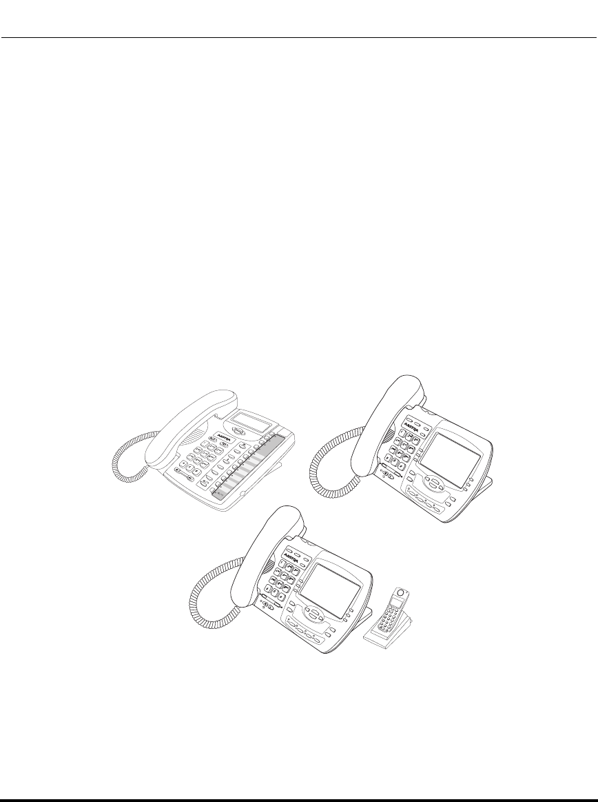
IP Phone Models
41-001160-03, Rev 00, Releaes 2.4 1-3
Overview
IP Phone Models
Description
All Aastra SIP IP Phone Models communicate over an IP network allowing you to
receive and place calls in the same manner as a regular business telephone.
All phone models support the Session Initiation Protocol (SIP). The 9480i CT and
6757i CT offers the base phone along with a cordless extension.
References
For more information about the features and installation requirements, see the
SIP IP Phone Installation Guide for your specific model.
The following illustrations show the types of IP Phone Models.
Options
Directory
Delete
Save
Mute
Xfer
Conf
L2
L3
L1
Conf
Services
Xfer
Icom
Hold
Redial
Goodbye
Options
9480i
Conf
Services
Xfer
Icom
Hold
Redial
Goodbye
Options
9480i CT
9480i
9480i CT
9143i
Draft 1
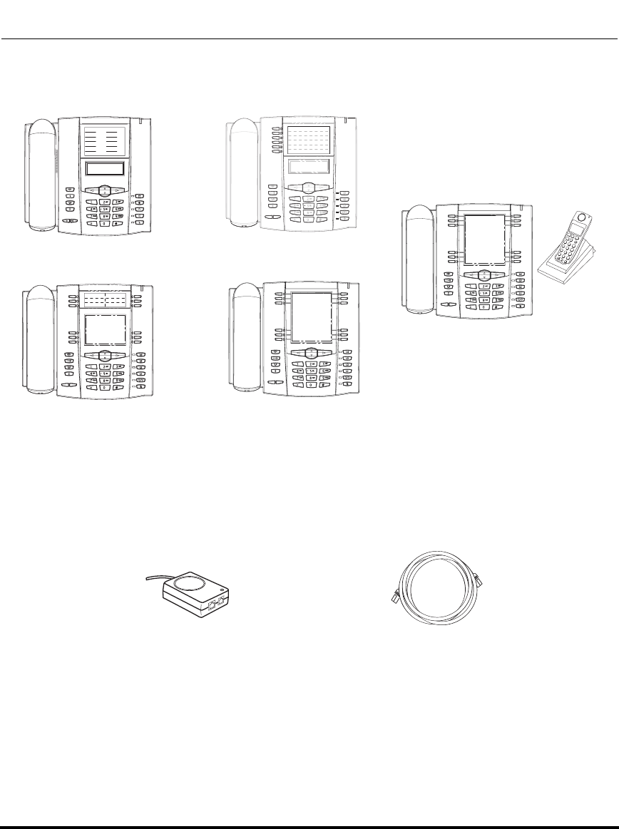
IP Phone Models
1-4 41-001160-03, Rev 00, Releaes 2.4
IP Phone Administrator Guide
Optional Accessories
The following are optional accessories for the IP Phones.
6755i 6757i
6757i CT
6753i
6751i
Power over Ethernet (PoE) Additional Ethernet Cable
(category 5/5e straight through
Inline Power Injector cable)
Draft 1
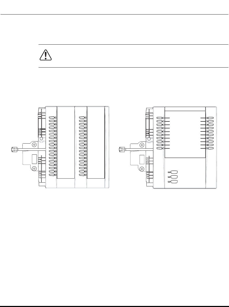
IP Phone Models
41-001160-03, Rev 00, Releaes 2.4 1-5
Overview
A Power over Ethernet (PoE) inline power injector supplies 48V power to the IP
phone through the Ethernet cable on pins 4 & 5 and 7 & 8.
Reference
For more information about installing the PoE and additional Ethernet cable, see
your phone-specific Installation Guide.
The M670i module adds 36 additional softkeys to the IP phone models 6753i,
6755i, 6757i, and 6757i CT. The M670i provides paper labels for each softkey. Up
to 3 modules can be piggy-backed to provide up to 108 additional softkeys for the
phone.
The M675i module adds 60 additional softkeys to the IP phone models 6755i,
6757i, and 6757i CT (using the 3 function keys on the bottom right of the unit).
The M675i module provides an LCD display for display softkey labels. Up to 3
modules can be piggy-backed to provide up to 180 additional softkeys for the
phone.
Reference
For more information about installing and using the expansion modules, see your
phone-specific Installation Guide and phone-specific User Guide.
Warning: Do not use this inline PoE power injector to power other
devices. See your phone-specific Installation Guide for more information.
M670i Expansion Module
for 6753i, 6755i, 6757i, and 6757i CT M675i Expansion Module
for 6755i, 6757i, and 6757i CT
Draft 1
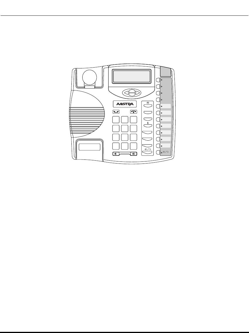
IP Phone Models
1-6 41-001160-03, Rev 00, Releaes 2.4
IP Phone Administrator Guide
Model 9143i IP Phone
This section provides brief information about the Model 9143i IP Phone. It
includes a list of features and describes the hard keys on the 9143i.
9143i Phone Features
• 3-line LCD screen
• 3 call appearance lines with LEDs
• 7 programmable keys
• Press-and-Hold speeddial key configuration feature
• Full-duplex speakerphone for handsfree calls
• Supports up to 9 call lines
• Headset support (modular connector)
• Built-in two-port, 10/100 Ethernet ports - lets you share a connection with
your computer
• Inline power support (based on 802.3af standard) which eliminates power
adapters.
• AC power adapter (included)
• Enhanced busy lamp fields*
• Set paging*
*Availability of feature dependant on your phone system or service provider.
Xfer
Conf
L2
L3
L1
Options
Save
Delete
Directory
Mute
ABC DEF
GHI JKL MNO
PQRS
TUV
WXYZ
1
4
3
6
2
5
798
0
*#
Draft 1
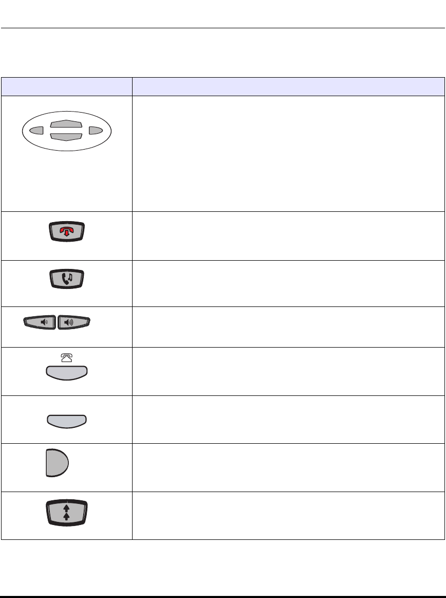
IP Phone Models
41-001160-03, Rev 00, Releaes 2.4 1-7
Overview
9143i Symbol Key Descriptions*
Keys Key Description
Navigation keys - Pressing the UP and DOWN arrow keys lets you view
different status and text messages on the LCD display (if there is more than
1 line of status/text messages). These buttons also let you scroll through
menu selections, such as the Options List.
Pressing the LEFT and RIGHT arrow keys lets you view the different line/
call appearances. While in the Options List, these keys allow you to exit or
enter the current option. When you are editing entries on the display,
pressing the LEFT arrow key erases the character on the left; pressing the
RIGHT arrow key sets the option.
Goodbye key - Ends an active call. The Goodbye key also exits an open
list, such as the Options List, without saving changes.
Hold key - Places an active call on hold. To retrieve a held call, press the
call appearance button beside the light that is flashing.
Volume control key - Adjusts the volume for the handset, headset, ringer,
and handsfree speaker.
Callers List key - Allows you to access the Callers List that stores up to
200 of the last calls received.
Conference key - Allows you to begin a conference call with up to 3 active
call parties.
Transfer key - Allows you to perform blind or consultative transfer of an
active call to another number. In blind transfer, you transfer the call without
waiting for the far end to answer. In consultative transfer, you wait for the far
end to answer before transferring the call.
Redial key - Redials a previously dialed number. The Redial key stores up
to 100 previously dialed numbers you can select from. Pressing the Redial
key twice simultaneously redials the last dialed number.
Conf
Xf
er
er
Draft 1
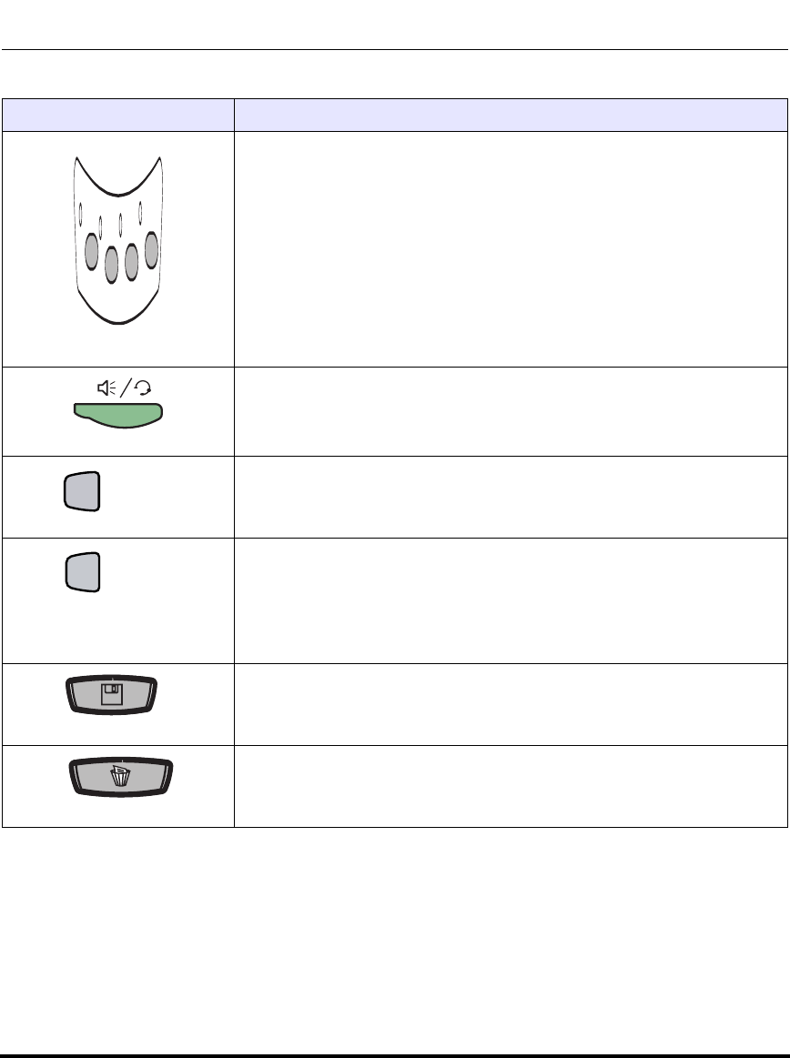
IP Phone Models
1-8 41-001160-03, Rev 00, Releaes 2.4
IP Phone Administrator Guide
Line/Call Appearance key - Connects you to a line or call. The Aastra
9143i IP Phone supports up to 3 line keys.
Handsfree key - Activates Handsfree for making and receiving calls
without lifting the handset. When the audio mode option is set, this key is
used to switch between a headset and the handsfree speakerphone.
Options key - Accesses options to customize your phone. Specific options
are available to your System Administrator only and are password
protected. Contact your System Administrator for more information.
Directory key - Accesses the Directory on the phone. The Directory List is
your personal phone book, conveniently stored within your phone. You can
enter up to 200 entries into the 9143i Directory by adding them manually, or
by saving the number and name from other lists stored on your phone.
Each entry can contain a maximum of 16 letters and
numbers.
Save key - Allows you to save entries when storing numbers and names in
Directory. Also allows you to save Option settings when using the
programmable keys.
Delete key - Allows you to remove entries from the Redial, Directory, or
Callers Lists.
Keys Key Description
L1
L1
L2
L2
L3
L3
L4
L4
Options
Director
y
Draft 1
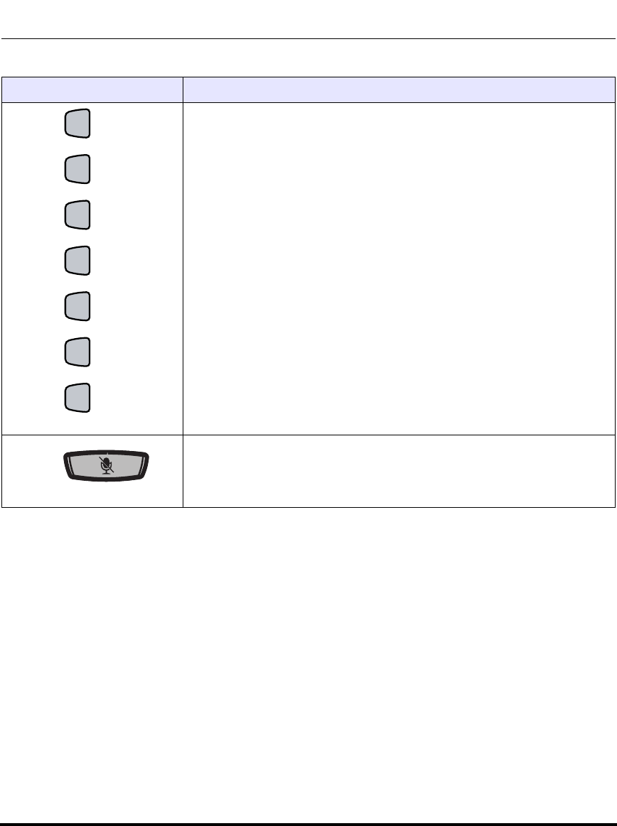
IP Phone Models
41-001160-03, Rev 00, Releaes 2.4 1-9
Overview
*See the Aastra 9143i User Guide for more information about each of these keys.
Programmable keys - Allows you to use the feature configured for that
key. You can program up to 7 keys with a specific function. By default, there
are no functions configured on the programmable keys (keys are
configured as “None”).
Note: For more information about configuring the programmable keys 1
through 7 to perform specific functions, see Chapter 5, “Configuring
Operational Features” the section, “Softkeys/Programmable Keys/Feature
Keys/Expansion Module Keys” on page 5-141.
Mute key - Mutes the microphone so that your caller cannot hear you (the
light indicator flashes when the microphone is on mute).
Keys Key Description
Draft 1

Model 9480i and 9480i CT IP Phones
This section provides brief information about the Models 9480i and 9480i CT IP
Phones. It includes a list of features and describes the hard keys on these models.
9480i and 9480i CT Phone Features
• 5 line graphical LCD screen with large backlit display
• 6 multi-functional, state-based softkeys
• Press-and-Hold speeddial key configuration feature
• 4 call appearance lines with LEDs
• Supports up to 9 call lines
• Speakerphone for handsfree calls
• Headset support (modular connector)
• Built-in-two-port, 10/100 Ethernet switch - lets you share a connection with
your computer.
• Inline power support (based on 802.3af standard) which eliminates power
adapters.
• AC power adapter (included)
• Enhanced busy lamp fields*
• Set paging*
*Availability of feature dependant on your phone system or service provider.
35i
35i
C
onf
onf Ser
vi
vic
es
es
Xf
er
er Ic
om
om
ABC
ABC
DEF
DEF
GHI
GHI
JKL
JKL
MNO
MNO
PQRS
PQ RS
TUV
TU V
WX
YZ
YZ
1
4
3
6
2
5
7 98
0
*
#
G
ood
oodbye
Options
Options
Hold
Hold R
edial
edial
L1
L1
L2
L2
L3
L3
L4
L4
35i
35i
C
onf
onf Ser
vi
vic
es
es
Xf
er
er Ic
om
om
ABC
ABC
DEF
DEF
GHI
GHI
JKL
JKL
MNO
MNO
PQRS
PQ RS
TUV
TU V
WX
YZ
YZ
1
4
3
6
2
5
7 98
0
*
#
G
ood
oodbye
Options
Options
Hold
Hold R
edial
edial
L1
L1
L2
L2
L3
L3
L4
L4
9480i 9480i CT
Draft 1
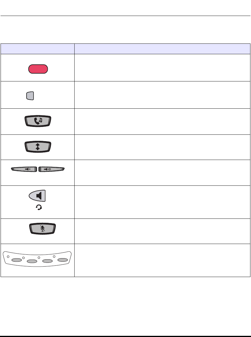
IP Phone Models
41-001160-03, Rev 00, Releaes 2.4 1-11
Overview
9480i and 9480i CT Key Descriptions*
Keys Key Description
Goodbye key - Ends an active call. The Goodbye key also exits an open
list, such as the Options List, without saving changes.
Options key - Accesses options to customize your phone. Your System
Administrator may have already customized some of your settings. Check
with your System Administrator before changing the administrator-only
options.
Hold key - Places an active call on hold. To retrieve a held call, press the
call appearance button beside the light that is flashing.
Redial key - Redials up to 100 previously dialed numbers. Pressing the
Redial key twice simultaneously redials the last dialed number.
Volume control key - Adjusts the volume for the handset, headset, ringer,
and handsfree speaker.
Handsfree key - Activates Handsfree for making and receiving calls
without lifting the handset. When the audio mode option is set, this key is
used to switch between a headset and the handsfree speakerphone.
Mute key - Mutes the microphone so that your caller cannot hear you (the
light indicator flashes when the microphone is on mute).
Line/Call Appearance key - Connects you to a line or call. The Aastra
9480i and 9480i CT IP phones support up to 4 line keys.
G
ood
oodbye
Options
L1
L1
L2
L2
L3
L3
L4
L4
Draft 1
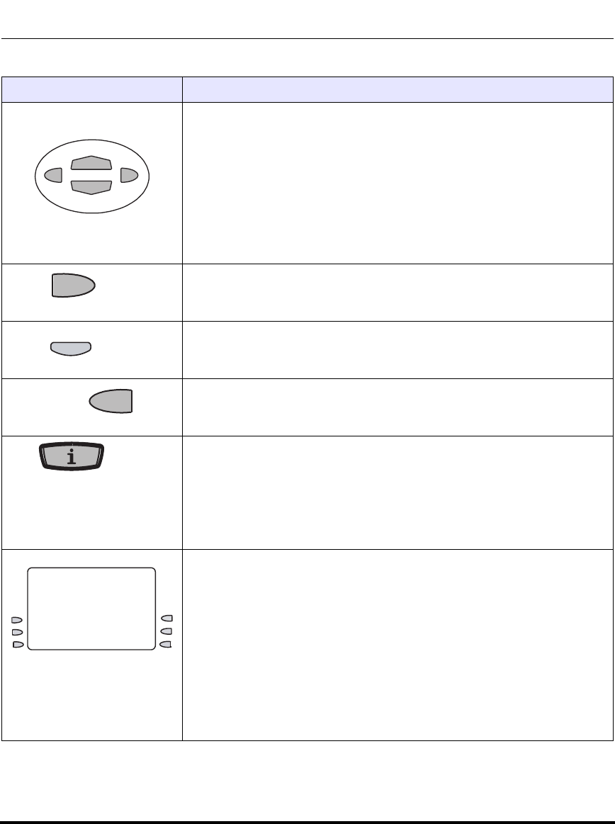
IP Phone Models
1-12 41-001160-03, Rev 00, Releaes 2.4
IP Phone Administrator Guide
*See the Aastra 9480i and 9480i CT User Guides for more information about each of these
keys.
Navigation keys - Pressing the UP and DOWN arrow keys lets you view
different status and text messages on the LCD display (if there is more than
1 line of status/text messages). These buttons also let you scroll through
menu selections, such as the Options List.
Pressing the LEFT and RIGHT arrow keys lets you view the different line/
call appearances. While in the Options List, these keys allow you to exit or
enter the current option. When you are editing entries on the display,
pressing the LEFT arrow key erases the character on the left; pressing the
RIGHT arrow key sets the option.
Transfer key - Transfers an active call to another number.
Conference key - Begins a conference call with the active call.
Icom key - Begins an intercom call to a remote extension and answers
incoming intercom calls. The 9480i and 9480i CT IP Phones also have
default softkey 4 configured as Icom.
Services key - Displays a list of Services available to your phone, if
specific services have been configured. The available Aastra services
include Directory & Callers Log. The 9480i and 9480i CT IP Phones also
have default softkey 1 configured as Services.
Note: Availability of the services feature is dependant on your phone
system and/or service provider.
Softkeys - 6 state-based softkeys on the 9480i and 9480i CT IP Phones.
By default, key 1 is assigned as WebApps. When you pick up the handset,
the following displays on key 1:
Dial - After entering a phone number from the keypad, you can press the
Dial softkey to immediately dial the number.
Note: For more information about configuring softkeys 1 through 6 to
perform specific functions, see Chapter 5, “Configuring Operational
Features” the section, “Softkeys/Programmable Keys/Feature Keys/
Expansion Module Keys” on page 5-141.
Keys Key Description
Xf
er
er
Conf
Ic
om
om
Draft 1

IP Phone Models
41-001160-03, Rev 00, Releaes 2.4 1-13
Overview
9480i CT Cordless Handset Features
• 5 line backlit display screen
• 2 multi-functional softkeys
• Programmable function key supports up to 14 functions
• Vibration Alerter
• Headset Jack
• Desk charging stand
Draft 1

IP Phone Models
1-14 41-001160-03, Rev 00, Releaes 2.4
IP Phone Administrator Guide
9480i CT Cordless Handset Key Descriptions*
*See the Aastra 9480i CT User Guide for more information about each of these keys.
Function # Function Description
1Receiver
2Volume key
During Ringing: Adjusts ringer volume
During a call: Adjusts receiver volume
During text mode (not in a call): Moves cursor right/left
3Display
4Features ƒ Key List
Access key to the programmed Feature Key List
Scrolls up when in the various lists
Adds a space during editing
5Softkeys
Activates feature or option shown on the display above
the keys
6Call key
Used to obtain dial tone
Also used as a Hold key
7Dial Pad
8Mute Key
When used, prevents the caller from hearing you
9Headset Jack
10 Status Light
11 Release key
To end calls and go on hook
Exits Menu and the various lists
12 Menu Key
Access key to the different Options
Scrolls down when in the various lists
Used as Backspace during editing
13 Redial Key
Displays the last 10 numbers dialed
14 Charging Jack
15 Charging Contacts
16 Microphone
Draft 1
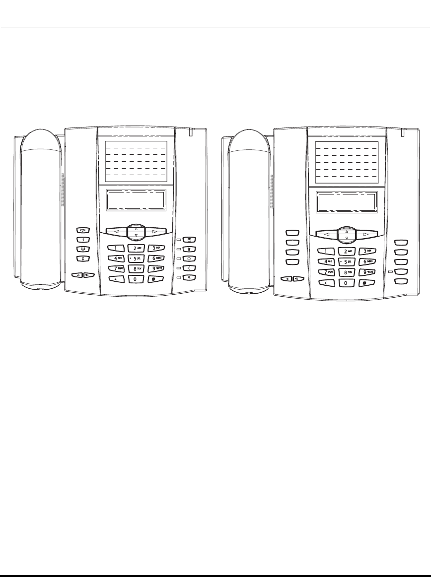
IP Phone Models
41-001160-03, Rev 00, Releaes 2.4 1-15
Overview
Model 6751i IP Phone
This section provides brief information about the Model 6751i IP Phone. It
includes a list of features and describes the hard keys on the 6751i. The 6751i is
available with a symbol keypad or a text keypad.
6751i Phone Features
• 3-line LCD screen
• 1 call appearance line
• Press-and-Hold speeddial key configuration feature
• Supports 1 call line with transfer capabilities
• Full-duplex speakerphone for monitoring calls
• Built-in two-port, 10/100 Ethernet ports - lets you share a connection with
your computer
• AC power adapter (sold separately)
Goodbye
Services
Hold
Redial
Save
Delete
Swap
Speaker
Mute
6751i with Symbol Keys 6751i with Text Keys
Draft 1
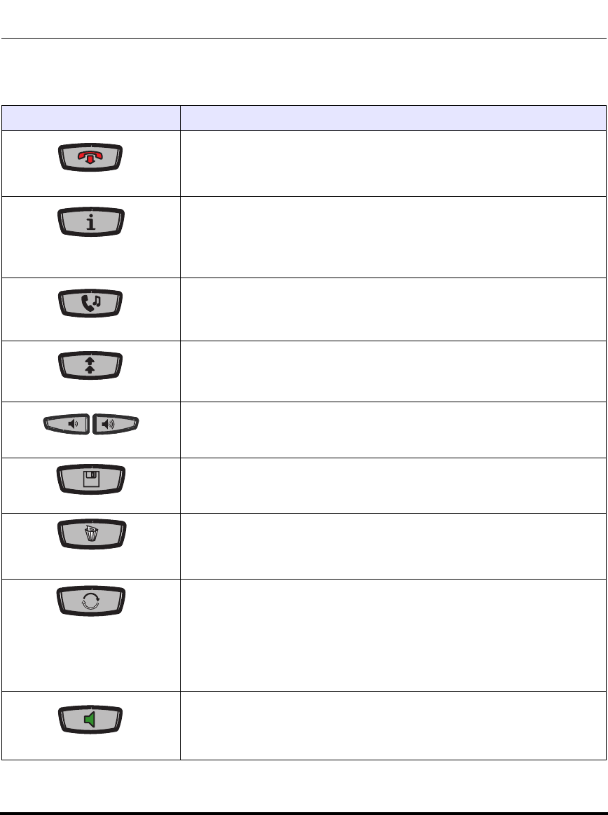
IP Phone Models
1-16 41-001160-03, Rev 00, Releaes 2.4
IP Phone Administrator Guide
6751i Symbol Key Descriptions*.
Keys Key Description
Goodbye key - Ends an active call. The Goodbye key also exits an open
list, such as the Options List, without saving changes.
Services key - Accesses services and options to customize your phone.
This keys also access the Directory List and Callers List. Your System
Administrator may have already customized some of your settings. Check
with your System Administrator before changing the administrator-only
options.
Hold key - Places an active call on hold. To retrieve a held call, press the
Hold key again.
Redial key - Redials up to 100 previously dialed numbers. Pressing the
Redial key twice simultaneously redials the last dialed number.
Volume control key - Adjusts the volume for the handset, ringer, and
handsfree speaker.
Save key - Saves names and numbers to the Directory List. Also saves
names and numbers from the Callers List to the Directory List.
Delete key - Deletes individual or all entries from the Directory List and
Callers List. Deletes all entries from the Redial List. You can also use this
key to backspace and delete a character when entering values for
speeddial softkeys.
Swap key - If you are on an active call and a second call comes in, you can
press the Swap key. This key places the first call on hold and answers the
second call. Pressing the Swap key again toggles between the two active
calls.
The Swap key works with two active calls only. A third call cannot be
accepted.
Speaker key - Activates Handsfree for receiving calls without lifting the
handset. Can be used on active calls to switch from the handset to
handsfree.
Draft 1

IP Phone Models
41-001160-03, Rev 00, Releaes 2.4 1-17
Overview
*See the Aastra 6751i User Guide for more information about each of these keys.
Mute key - Mutes the microphone so that your caller cannot hear you.
Navigation keys - Pressing the UP and DOWN arrow keys lets you view
different status and text messages on the LCD display (if there is more than
1 line of status/text messages). These buttons also let you scroll through
menu selections, such as the Options List.
UP Arrow - This key also acts as a Transfer Key, allowing you to transfer
calls when required.
DOWN Arrow - This key also acts as a Conference Key, allowing you to join
conferences when required.
Pressing the UP and DOWN arrow keys lets you view the lines on the LCD.
While in the Options List, the navigation keys allow you to exit or enter the
current option. When you are editing entries on the display, pressing the
LEFT arrow key erases the character on the left; pressing the RIGHT arrow
key sets the option.
Keys Key Description
Draft 1

IP Phone Models
1-18 41-001160-03, Rev 00, Releaes 2.4
IP Phone Administrator Guide
6751i Text Key Descriptions*.
Keys Key Description
Goodbye key - Ends an active call. The Goodbye key also exits an open
list, such as the Options List, without saving changes.
Services key - Accesses services and options to customize your phone.
This keys also access the Directory List and Callers List. Your System
Administrator may have already customized some of your settings. Check
with your System Administrator before changing the administrator-only
options.
Hold key - Places an active call on hold. To retrieve a held call, press the
Hold key again.
Redial key - Redials up to 100 previously dialed numbers. Pressing the
Redial key twice simultaneously redials the last dialed number.
Volume control key - Adjusts the volume for the handset, ringer, and
handsfree speaker.
Save key - Saves names and numbers to the Directory List. Also saves
names and numbers from the Callers List to the Directory List.
Delete key - Deletes individual or all entries from the Directory List and
Callers List. Deletes all entries from the Redial List. You can also use this
key to backspace and delete a character when entering values for
speeddial softkeys.
Swap key - If you are on an active call and a second call comes in, you can
press the Swap key. This key places the first call on hold and answers the
second call. Pressing the Swap key again toggles between the two active
calls.
The Swap key works with two active calls only. A third call cannot be
accepted.
Speaker key - Activates Handsfree for receiving calls without lifting the
handset. Can be used on active calls to switch from the handset to
handsfree.
Draft 1

IP Phone Models
41-001160-03, Rev 00, Releaes 2.4 1-19
Overview
*See the Aastra 6751i User Guide for more information about each of these keys.
Mute key - Mutes the microphone so that your caller cannot hear you.
Navigation keys - Pressing the UP and DOWN arrow keys lets you view
different status and text messages on the LCD display (if there is more than
1 line of status/text messages). These buttons also let you scroll through
menu selections, such as the Options List.
UP Arrow - This key also acts as a Transfer Key, allowing you to transfer
calls when required.
DOWN Arrow - This key also acts as a Conference Key, allowing you to join
conferences when required.
Pressing the UP and DOWN arrow keys lets you view the lines on the LCD.
While in the Options List, the navigation keys allow you to exit or enter the
current option. When you are editing entries on the display, pressing the
LEFT arrow key erases the character on the left; pressing the RIGHT arrow
key sets the option.
Keys Key Description
Draft 1
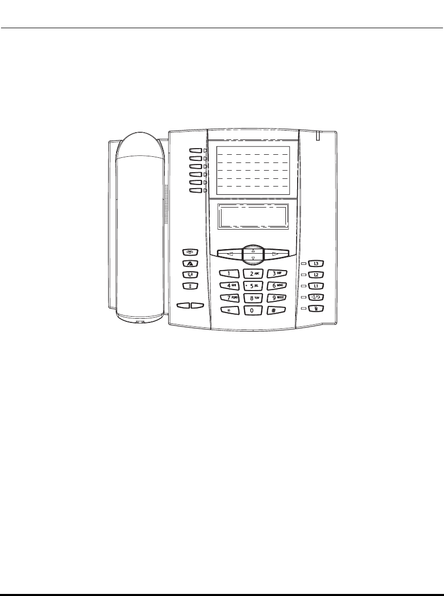
IP Phone Models
1-20 41-001160-03, Rev 00, Releaes 2.4
IP Phone Administrator Guide
Model 6753i IP Phone
This section provides brief information about the Model 6753i IP Phone. It
includes a list of features, and describes the hard keys and default programmable
keys on the 6753i.
6753i Phone Features
• 3-line LCD screen
• 6 top keys - all 6 keys are programmable
• 3 call appearance lines with LEDs
• Press-and-Hold speeddial key configuration feature
• Supports up to 9 call lines
• Full-duplex speakerphone for handsfree calls
• Headset support (modular connector)
• Built-in two-port, 10/100 Ethernet ports - lets you share a connection with
your computer
• AC power adapter (included)
• Enhanced busy lamp fields*
• Set paging*
*Availability of feature dependant on your phone system or service provider.
Draft 1
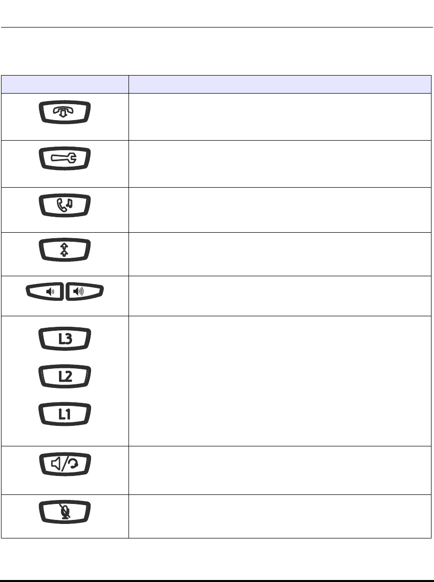
IP Phone Models
41-001160-03, Rev 00, Releaes 2.4 1-21
Overview
6753i Key Descriptions*
Keys Key Description
Goodbye key - Ends an active call. The Goodbye key also exits an open
list, such as the Options List, without saving changes.
Options key - Accesses options to customize your phone. Your System
Administrator may have already customized some of your settings. Check
with your System Administrator before changing the administrator-only
options.
Hold key - Places an active call on hold. To retrieve a held call, press the
call appearance button beside the light that is flashing.
Redial key - Redials up to 100 previously dialed numbers. Pressing the
Redial key twice simultaneously redials the last dialed number.
Volume control key - Adjusts the volume for the handset, headset, ringer,
and handsfree speaker.
Line/Call Appearance key - Connects you to a line or call. The Aastra
6753i IP phone supports up to 3 line keys.
Handsfree key - Activates Handsfree for making and receiving calls
without lifting the handset. When the audio mode option is set, this key is
used to switch between a headset and the handsfree speakerphone.
Mute key - Mutes the microphone so that your caller cannot hear you (the
light indicator flashes when the microphone is on mute).
Draft 1
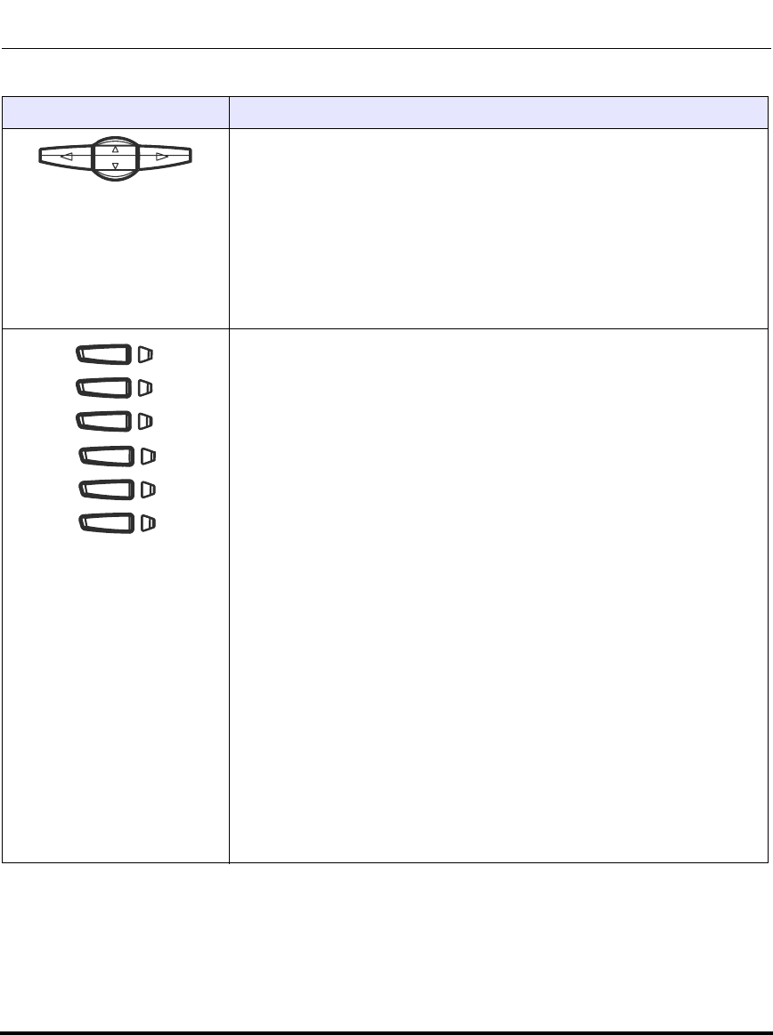
IP Phone Models
1-22 41-001160-03, Rev 00, Releaes 2.4
IP Phone Administrator Guide
*See the Aastra 6753i User Guide for more information about each of these keys.
Navigation keys - Pressing the UP and DOWN arrow keys lets you view
different status and text messages on the LCD display (if there is more
than 1 line of status/text messages). These buttons also let you scroll
through menu selections, such as the Options List.
Pressing the LEFT and RIGHT arrow keys lets you view the different line/
call appearances. While in the Options List, these keys allow you to exit or
enter the current option. When you are editing entries on the display,
pressing the LEFT arrow key erases the character on the left; pressing the
RIGHT arrow key sets the option.
Programmable keys - 6 Top Keys - all 6 keys are programmable.
Keys 1 and 2 are designated as the SAVE and DELETE keys, respectively.
These keys are locked but can be unlocked and made configurable if
required by the System Administrator.
The following are the default functions for the programmable keys on the
6753i IP phone:
1 - SAVE Allows you to save numbers and/or names to the
Directory. Using this key, you enter the number,
name, and line (or speeddial key) to record in the
Directory List.
2 - DELETE Allows you to delete a single entry or all entries from
the Directory List and Callers List.
3 - DIRECTORY Displays up to 200 names and phone numbers
(stored in alphabetical order).
4 - CALLERS LIST Accesses the last 200 calls received.
5 - TRANSFER Transfers the active call to another number.
6 - CONFERENCE Begins a conference call with the active call.
Notes:
1. For more information about programming the SAVE and DELETE
keys, see “Locking/Unlocking the SAVE and DELETE keys (6753i)” on
page 5-50.
2, For more information about configuring keys 1 thru 6 to perform
specific functions, see Chapter 5 the section, “Softkeys/Programmable
Keys/Feature Keys/Expansion Module Keys” on page 5-141.
Keys Key Description
Draft 1
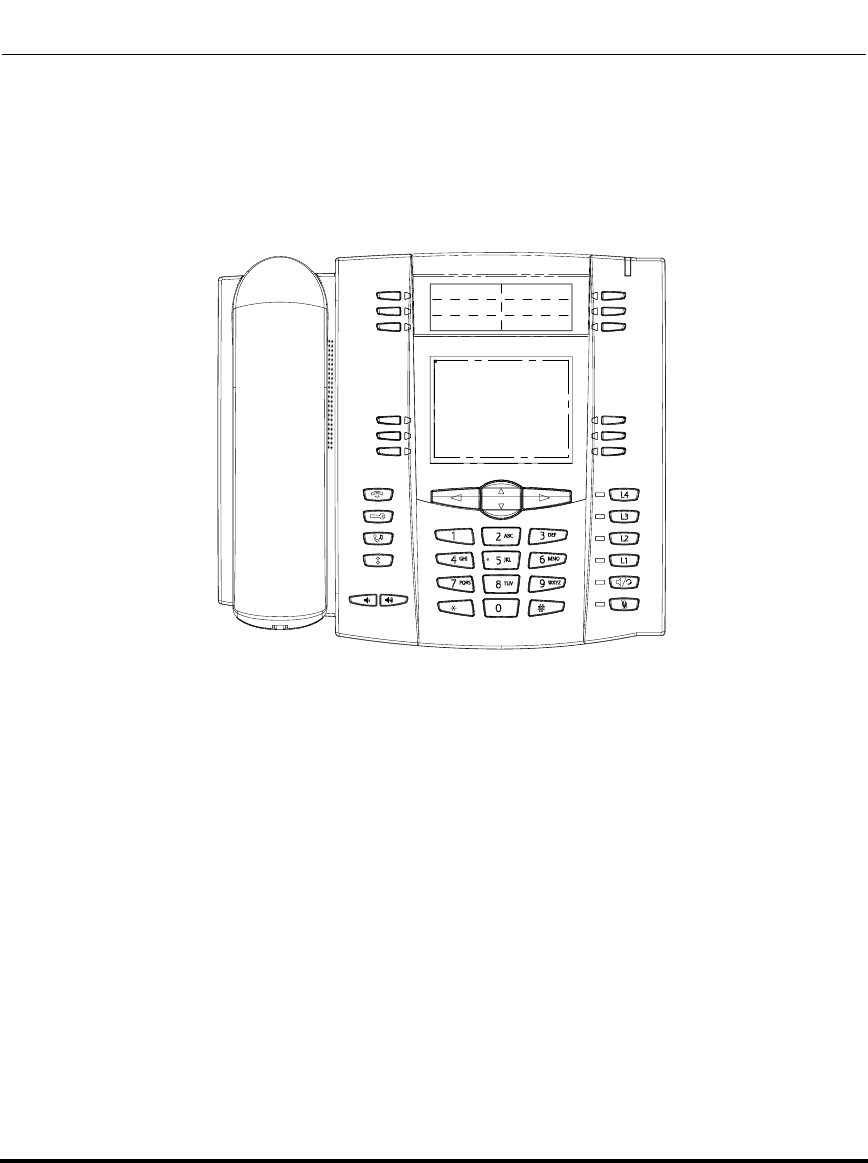
IP Phone Models
41-001160-03, Rev 00, Releaes 2.4 1-23
Overview
Model 6755i IP Phone
This section provides brief information about the Model 6755i IP Phone. It
includes a list of features, and describes the hard keys, default programmable
keys, and default softkeys on the 6755i.
6755i Phone Features
• 8 line graphical LCD screen (144 x 75 pixels) with white backlight
• 12 programmable keys
• 6 Top keys:Programmable hard keys
• 6 Bottom keys:Programmable state-based softkeys
• 4 call appearance lines with LEDs
• Press-and-Hold speeddial key configuration feature
• Supports up to 9 call lines
• Full-duplex speakerphone for handsfree calls
• Headset support (modular connector)
• Built-in-two-port, 10/100 Ethernet switch - lets you share a connection with
your computer.
Draft 1
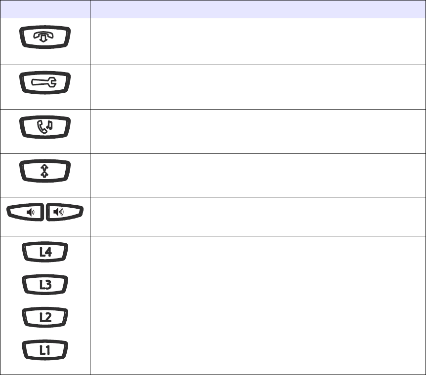
• Inline power support (based on 802.3af standard) which eliminates power
adapters.
• AC power adapter (included)
• Enhanced busy lamp fields*
• Set paging*
*Availability of feature dependant on your phone system or service provider.
6755i Key Descriptions*
Keys Key Description
Goodbye key - Ends an active call. The Goodbye key also exits an open list, such
as the Options List, without saving changes.
Options key - Accesses options to customize your phone. Your System
Administrator may have already customized some of your settings. Check with your
System Administrator before changing the administrator-only options.
Hold key - Places an active call on hold. To retrieve a held call, press the call
appearance button beside the light that is flashing.
Redial key - Redials up to 100 previously dialed numbers. Pressing the Redial key
twice simultaneously redials the last dialed number.
Volume control key - Adjusts the volume for the handset, headset, ringer, and
handsfree speaker.
Line/Call Appearance key - Connects you to a line or call. The Aastra 6755i IP
phone supports up to 4 line keys.
Draft 1
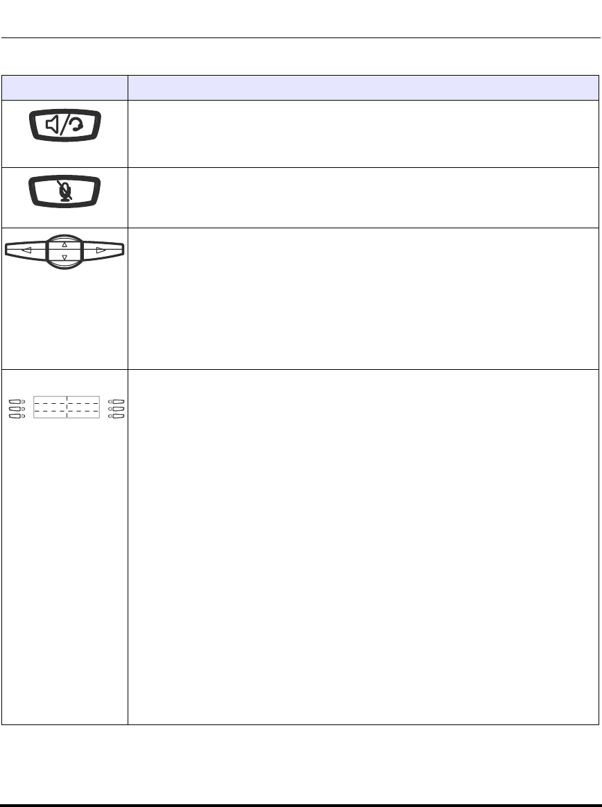
IP Phone Models
41-001160-03, Rev 00, Releaes 2.4 1-25
Overview
Handsfree key - Activates Handsfree for making and receiving calls without lifting
the handset. When the audio mode option is set, this key is used to switch between
a headset and the handsfree speakerphone.
Mute key - Mutes the microphone so that your caller cannot hear you (the light
indicator flashes when the microphone is on mute).
Navigation keys - Pressing the UP and DOWN arrow keys lets you view different
status and text messages on the LCD display (if there is more than 1 line of status/
text messages). These buttons also let you scroll through menu selections, such as
the Options List.
Pressing the LEFT and RIGHT arrow keys lets you view the different line/call
appearances. While in the Options List, these keys allow you to exit or enter the
current option. When you are editing entries on the display, pressing the LEFT arrow
key erases the character on the left; pressing the RIGHT arrow key sets the option.
Programmable keys - 6 Top keys: programmable hard keys (up to 6 programmable
functions)
By default, the top keys 1 through 4 are assigned as Services, Directory, Callers List,
and Intercom, respectively. Keys 5 and 6 have no assigned functions. All 6 keys are
programmable and can be assigned to perform specific functions.
The following are the default functions for the programmable keys on the 6755i IP
phone:
1 - SERVICES Accesses enhanced features and services such as XML
applications and voicemail, provided by third parties.
2 - DIRECTORY Displays up to 200 names and phone numbers (stored in
alphabetical order).
3 - CALLERS LIST Accesses the last 200 calls received.
4 - ICOM Accesses another extension on the network.
5 - NONE No assigned function.
6 - NONE No assigned function.
Note: For more information about configuring the programmable keys 1 through 6 to
perform specific functions, see Chapter 5, “Configuring Operational Features” the
section, “Softkeys/Programmable Keys/Feature Keys/Expansion Module Keys” on
page 5-141.
Keys Key Description
Draft 1

IP Phone Models
1-26 41-001160-03, Rev 00, Releaes 2.4
IP Phone Administrator Guide
*See the Aastra 6755i User Guide for more information about each of these keys.
Softkeys - 6 Bottom keys: programmable state-based softkeys (up to 20
programmable functions).
By default, keys 1 through 6 have no assigned functions. You can configure all 6
bottom softkeys to perform specific functions on the 6755i IP phone. However, after
you lift the handset, there are specific static softkeys that display that cannot be
changed. These are as follows:
1 - DIAL Allows you to dial out on the phone.
2 - CONF Begins a conference call with the active phone.
3 - XFER Transfers the active call to another number.
Note: For more information about configuring softkeys 1 through 6 to perform
specific functions, see Chapter 5, “Configuring Operational Features” the section,
“Softkeys/Programmable Keys/Feature Keys/Expansion Module Keys” on
page 5-141.
Keys Key Description
Draft 1
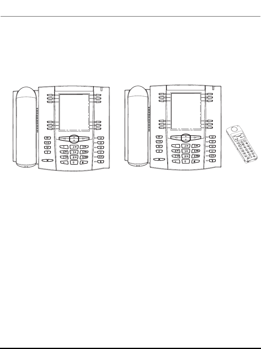
IP Phone Models
41-001160-03, Rev 00, Releaes 2.4 1-27
Overview
Model 6757i and 6757i CT IP Phones
This section provides brief information about the Model 6757i IP Phone. It
includes a list of features, and describes the hard keys and default softkeys on the
6757i.
6757i and 6757i CT Phone Features
• 11 line graphical LCD screen (144 x 128 pixels) with white backlight
• 12 multi-functional softkeys
- 6 Top Keys: programmable static softkeys
- 6 Bottom Keys: programmable state-based softkeys
• 4 call appearance lines with LEDs
• Press-and-Hold speeddial key configuration feature
• Supports up to 9 call lines
• Full-duplex speakerphone for handsfree calls
• Headset support (modular connector)
• Built-in-two-port, 10/100 Ethernet switch - lets you share a connection with
your computer.
6757i 6757i CT
Draft 1
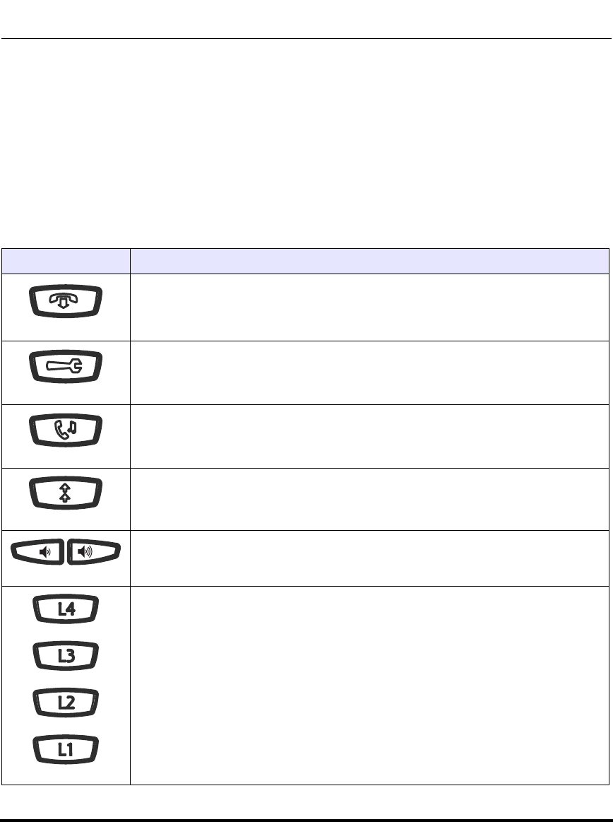
IP Phone Models
1-28 41-001160-03, Rev 00, Releaes 2.4
IP Phone Administrator Guide
• Inline power support (based on 802.3af standard) which eliminates power
adapters.
• AC power adapter (included)
• Enhanced busy lamp fields*
• Set paging*
*Availability of feature dependant on your phone system or service provider.
6757i and 6757i CT Key Descriptions*
Keys Key Description
Goodbye key - Ends an active call. The Goodbye key also exits an open list, such
as the Options List, without saving changes.
Options key - Accesses options to customize your phone. Your System
Administrator may have already customized some of your settings. Check with your
System Administrator before changing the administrator-only options.
Hold key - Places an active call on hold. To retrieve a held call, press the call
appearance button beside the light that is flashing.
Redial key - Redials up to 100 previously dialed numbers. Pressing the Redial key
twice simultaneously redials the last dialed number.
Volume control key - Adjusts the volume for the handset, headset, ringer, and
handsfree speaker.
Line/Call Appearance key - Connects you to a line or call. The Aastra 6757i IP
phone supports up to 4 line keys.
Draft 1
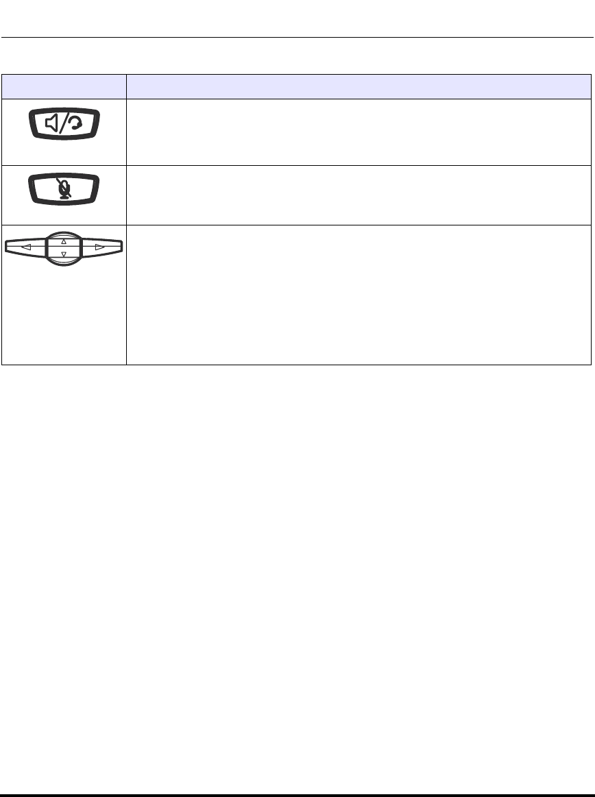
IP Phone Models
41-001160-03, Rev 00, Releaes 2.4 1-29
Overview
Handsfree key - Activates Handsfree for making and receiving calls without lifting
the handset. When the audio mode option is set, this key is used to switch between
a headset and the handsfree speakerphone.
Mute key - Mutes the microphone so that your caller cannot hear you (the light
indicator flashes when the microphone is on mute).
Navigation keys - Pressing the UP and DOWN arrow keys lets you view different
status and text messages on the LCD display (if there is more than 1 line of status/
text messages). These buttons also let you scroll through menu selections, such as
the Options List.
Pressing the LEFT and RIGHT arrow keys lets you view the different line/call
appearances. While in the Options List, these keys allow you to exit or enter the
current option. When you are editing entries on the display, pressing the LEFT arrow
key erases the character on the left; pressing the RIGHT arrow key sets the option.
Keys Key Description
Draft 1

IP Phone Models
1-30 41-001160-03, Rev 00, Releaes 2.4
IP Phone Administrator Guide
*See the Aastra 6757i or 6757i CT User Guide for more information about each of these keys.
Softkeys - 12 softkeys on the 6757i IP Phone.
- 6 Top Keys: programmable static softkeys (up to 10 programmable functions)
- 6 Bottom Keys: programmable state-based softkeys (up to 20 programmable
functions)
By default, the top softkeys 1 through 4 are assigned as Services, Directory, Callers
List, and Intercom, respectively. Keys 5 and 6 have no assigned functions. All 6 keys
are programmable and can be assigned to perform specific functions.
The following are the default functions for the top softkeys on the 6757i IP phone:
1 - SERVICES Accesses enhanced features and services such as XML
applications and voicemail, provided by third parties.
2 - DIRECTORY Displays up to 200 names and phone numbers (stored in
alphabetical order).
3 - CALLERS LIST Accesses the last 200 calls received.
4 - ICOM Accesses another extension on the network.
5 - NONE No assigned function.
6 - NONE No assigned function.
By default, the bottom softkeys 7 through 12 have no assigned functions. You can
configure all 6 bottom softkeys to perform specific functions on the 6757i IP phone.
However, after you lift the handset, there are specific static softkeys that display that
cannot be changed. These are as follows:
7- DIAL Allows you to dial out on the phone.
8- CONF Begins a conference call with the active phone.
9- XFER Transfers the active call to another number.
Note: For more information about programming the softkeys to perform specific
functions, see Chapter 5, “Configuring Operational Features” the section, “Softkeys/
Programmable Keys/Feature Keys/Expansion Module Keys” on page 5-141.
Keys Key Description
Draft 1

IP Phone Models
41-001160-03, Rev 00, Releaes 2.4 1-31
Overview
6757i CT Cordless Handset Features
• 5 line backlit display screen
• 2 multi-functional softkeys
• Programmable function key supports up to 14 functions
• Vibration Alerter
• Headset Jack
• Desk charging stand
6757i CT Cordless Handset Key Descriptions
Function # Function Description
1Receiver
2Volume key
During Ringing: Adjusts ringer volume
During a call: Adjusts receiver volume
During text mode (not in a call): Moves cursor right/left
3Display
4Features ƒ Key List
Access key to the programmed Feature Key List
Scrolls up when in the various lists
Adds a space during editing
Draft 1

IP Phone Models
1-32 41-001160-03, Rev 00, Releaes 2.4
IP Phone Administrator Guide
Function # Function Description
5Softkeys
Activates feature or option shown on the display above
the keys
6Call key
Used to obtain dial tone
Also used as a Hold key
7Dial Pad
8Mute Key
When used, prevents the caller from hearing you
9Headset Jack
10 Status Light
11 Release key
To end calls and go on hook
Exits Menu and the various lists
12 Menu Key
Access key to the different Options
Scrolls down when in the various lists
Used as Backspace during editing
13 Redial Key
Displays the last 10 numbers dialed
14 Charging Jack
15 Charging Contacts
16 Microphone
Draft 1

Firmware Installation Information
41-001160-03, Rev 00, Releaes 2.4 1-33
Overview
Firmware Installation Information
Description
The firmware setup and installation for the IP phone can be done using any of the
following:
• Phone User Interface via the keypad (Phone UI)
• Aastra Web-based user interface (Aastra Web UI)
When the IP phone is initialized for the first time, DHCP is enabled by default.
Depending on the type of configuration server setup you may have, the IP phone
may download a firmware version automatically, or you may need to download it
manually.
Installation Considerations
The following considerations must be made before connecting the IP phone to the
network:
• If you are planning on using dynamic IP addresses, make sure a DHCP server
is enabled and running on your network.
• If you are not planning on using dynamic IP addresses, see Chapter 4, the
section, “Configuring Network Settings Manually” on page 4-24 for manually
setting up an IP address.
To install the IP phone hardware and cabling, refer to the model-specific
SIP IP Phone Installation Guide.
Draft 1

Firmware Installation Information
1-34 41-001160-03, Rev 00, Releaes 2.4
IP Phone Administrator Guide
Installation Requirements
The following are general requirements for setting up and using your SIP IP
phone:
• SIP-based IP PBX system or network installed and running with a SIP
account created for the IP phone.
• Access to a Trivial File Transfer Protocol (TFTP), File Transfer Protocol
(FTP), Hypertext Transfer Protocol (HTTP) server, or HyperText Transfer
Protocol over Secure Sockets Layer (SSL) (HTTPS).
• Ethernet/Fast Ethernet LAN (10/100 Mb)
• Category 5/5e straight through cabling
•Power source
— For Ethernet networks that supply in-line power to the phone (IEEE
802.3af):
— For power, use the Ethernet cable (supplied) to connect from the
phone directly to the network for power. (No 48v AC power adapter
required.)
— For Ethernet networks that DO NOT supply power to the phone:
— For power, use the 48V AC Power Adapter (included) to connect
from the DC power port on the phone to a power source.
or
— (optional) - For power, use a Power over Ethernet (PoE) power
injector or a PoE switch. A PoE power injector is available as an
optional accessory from Aastra Telecom. Contact your Administrator
for more information.
Draft 1

Firmware Installation Information
41-001160-03, Rev 00, Releaes 2.4 1-35
Overview
Configuration Server Requirement
A basic requirement for setting up the IP phone is to have a configuration server.
The configuration server allows you to:
• Store the firmware images that you need to download to your IP phone.
• Stores configuration files for the IP phone
• Stores the software when performing software upgrades to the IP phone
Reference
To set the protocol for your configuration server, see Chapter 4, the section,
“Configuring the Configuration Server Protocol” on page 4-108.
To update the firmware on your phone, see Chapter 8, “Upgrading the Firmware”.
Note: If you use TFTP, the configuration server must be able to accept
connections anonymously.
Draft 1
Firmware and Configuration Files
1-36 41-001160-03, Rev 00, Releaes 2.4
IP Phone Administrator Guide
Firmware and Configuration Files
Description
When the IP phone is initialized for the first time, DHCP is enabled by default
allowing the phone to automatically get its IP address from the network. Upon
bootup, the phone also automatically updates it firmware and configuration files
from the configuration server using the default TFTP protocol.
The IP Phones support TFTP, FTP, HTTP, and HTTPS as download protocols.
You can change the protocol server that you use to download firmware and
configuration files, and can perform the download manually or configure the
phone to download them automatically.
The firmware consists of a single file called:
•<phone model>.st (for example, 55i.st (for 6755i)) - This file contains
information about the specific IP Phone model and contains the language
packs to load to the phone.
The configuration files consist of two files called:
•aastra.cfg - This file contains configuration information about the IP Phone.
•<MAC>.cfg (for example, 00085D1610DE.cfg) - This file contains
configuration information about the IP Phone.
Note: Automatic download is dependant on your configuration server
setup. For more information about manual and automatic download of
firmware, see Chapter 8, “Upgrading the Firmware.” For more
information on changing the download protocol on your phone, see
Chapter 4, the section, “Configuring the Configuration Server Protocol”
on page 4-108.
Draft 1
Firmware and Configuration Files
41-001160-03, Rev 00, Releaes 2.4 1-37
Overview
The following table provides the files that the phone requests from the
configuration server during bootup of the phone:
The IP Phone firmware file includes all the necessary files you need for your
phone, including the language files. Loading the language files to your phone(s) is
optional.
Reference
For more information about loading language files and using the various
languages on the IP phone, see Chapter 5, the section, “Language” on page 5-34.
IP Phone Model Associated Firmware Configuration Files Language Files
9143i 9143i.st aastra.cfg
<MAC>.cfg
(for example, 00085D1610DE.cfg)
lang_de.txt (German)
lang_es.txt (Spanish)
lang_es_mx.txt (Mexican Spanish)
lang_fr.txt (French)
lang_fr_ca.txt (Canadian French)
lang_it.txt (Italian)
9480i 9480i.st
9480i CT 9480iCT.st
6751i 51i.st
6753i 53i.st
6755i 55i.st
6757i 57i.st
6757i CT 57iCT.st
Draft 1

Firmware and Configuration Files
1-38 41-001160-03, Rev 00, Releaes 2.4
IP Phone Administrator Guide
Configuration File Precedence
Aastra IP phones can accept two sources of configuration data:
• The server configuration most recently downloaded/cached from the
configuration server files, aastra.cfg/<mac>.cfg (or the aastra.tuz/<mac>.tuz
encrypted equivalents).
• Local configuration changes stored on the phone that were entered using
either the IP phone UI or the Aastra Web UI
In the event of conflicting values set by the different methods, values are applied
in the following sequence:
1. Default values hard-coded in the phone software
2. Values downloaded from the configuration server
3. Values stored locally on the phone
The last values to be applied to the phone configuration are the values that take
effect.
For example, if a parameter’s value is set in the local configuration (via Aastra
Web UI or IP phone UI) and the same value was also set differently in one of the
<mac>.cfg/aastra.cfg files on the configuration server, the local configuration
value is the value that takes effect because that is the last value applied to the
configuration.
Draft 1

Firmware and Configuration Files
41-001160-03, Rev 00, Releaes 2.4 1-39
Overview
Installing the Firmware/Configuration Files
The following procedure describes how to install the firmware and configuration
files.
Step Action
1 If DHCP is disabled, manually enter the configuration server’s IP address. For details on manually
setting DHCP, see Chapter 4, the section “DHCP” on page 4-4.
2 Copy the firmware file <phone model>.st to the root directory of the configuration server. The IP
phone accepts the new firmware file only if it is different from the firmware currently loaded on the IP
phone.
Note: The <phone model> attribute is the IP phone model (i.e., 9143i.st, 9480i.st, 9480iCT.st, 51i.st,
53i.st, 55i.st, 57i.st, 57iCT.st).
3 Copy the Aastra configuration files (aastra.cfg and <mac>.cfg) to the root directory of the
configuration server.
Note: The <mac> attribute represents the actual MAC address of your phone.
(i.e., 00085D030996.cfg).
4Note: Restart the IP phone as described in Chapter 3, “Restarting Your Phone” on page 3-13.
Draft 1
Draft 1
41-001160-03, Rev 00, Releaes 2.4 2-1
Chapter 2
Configuration Interface Methods
About this chapter
Introduction
This chapter describes the methods you, as an Administrator, can use to configure
the IP phones.
Topics
This chapter covers the following topics:
Note: Features, characteristics, requirements, and configuration that are
specific to a particular IP phone models are indicated where required in
this guide.
Topic Page
Configuration Methods page 2-2
IP Phone UI page 2-2
Aastra Web UI page 2-6
Configuration Files (Administrator Only) page 2-17
Draft 1
Configuration Methods
2-2 41-001160-03, Rev 00, Releaes 2.4
IP Phone Administrator Guide
Configuration Methods
Description
You can use the following to setup and configure the IP phone:
• IP phone UI
•Aastra Web UI
• Configuration files
The following paragraphs describe each method of configuring the IP Phone.
IP Phone UI
The IP Phone User Interface (UI) provides an easy way to access features and
functions for using and configuring the IP phone. An Administrator can configure
all features and functions on the phone. A User can configure a subset of these
features and functions. Users of the IP phones should see their Model-specific
User’s Guide for available features and functions to configure.
You use the phone’s hard keys and keypad to configure specific features on the IP
phone. By default, specific softkeys/programmable keys on each phone model can
also access the Directory List and Callers List, and initiate transfers and
conference calls.
Reference
Refer to Chapter 1, the section “IP Phone Models” on page 1-3 for keys specific to
your phone model.
For more information about using the hard keys on each phone, see Chapter 5, the
section, “Locking IP Phone Keys” on page 5-49.
For more information about the softkeys/programmable keys, see Chapter 5, the
section, “Softkeys/Programmable Keys/Feature Keys/Expansion Module Keys”
on page 5-141.
Note: There are specific parameters you can configure using only the IP
Phone UI, only and Aastra Web UI, only the configuration files, or a
combination of any of these methods. For more information about
configuring the phone, see Chapter 4, Chapter 5, and Chapter 6.
Draft 1
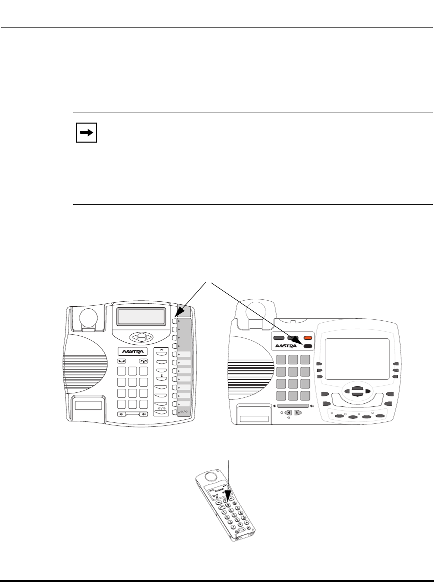
Configuration Methods
41-001160-03, Rev 00, Releaes 2.4 2-3
Configuration Interface Methods
Options Key
The Options key allows you to access the "Options List" on the IP phone.
Accessible options in this list are for both user and Administrator use. An
Administrator must enter a password for administrator options.
This document describes the administrator options only. For a description of the
user options in the "Options List", see your model-specific SIP IP Phone User
Guide.
The following illustrations indicate the location of the Options Key on each phone
model.
Note: An Administrator can apply a simplified options menu to the IP
phones. An Administrator can also enable and disable the use of an
Administrator password protection in the IP phone UI. These features are
configurable using the configuration files only.
For more information about these features, see Chapter 3, the section,
“Simplified IP Phone UI Options Menu” on page page 3-5, and Chapter
5, the section, “Administrator Passwords” on page 5-9.
9480i/9480i CT
9480i CT Handset
Options Key
Options Key
9143i
Xfer
Conf
L2
L3
L1
Options
Save
Delete
Directory
Mute
ABC DEF
GHI JKL MNO
PQRS
TUV
WXYZ
1
4
3
6
2
5
798
0
*#
9480i
Conf Services
Xfer Icom
ABC DEF
GHI JKL MNO
PQRS
TUV
WXYZ
1
4
3
6
2
5
798
0
*
#
Goodbye
Options
Hold Redial
L1 L2 L3 L4
Draft 1
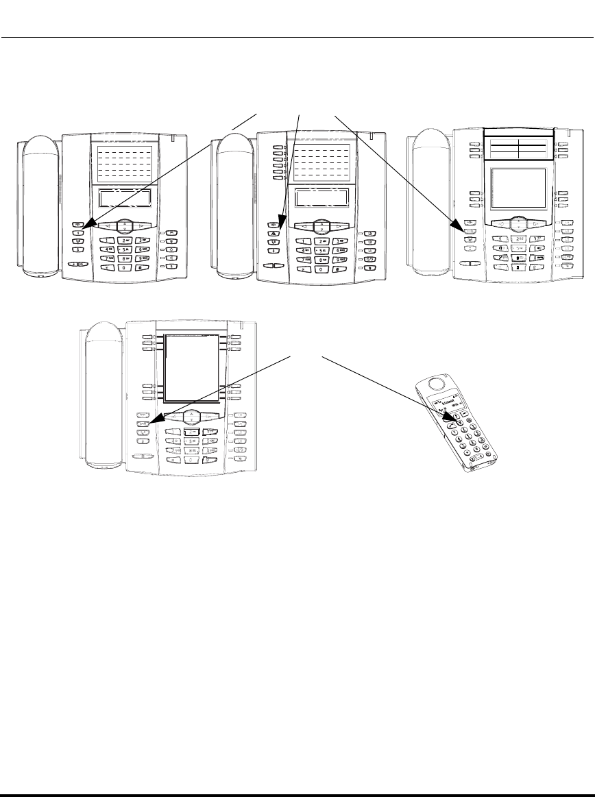
Configuration Methods
2-4 41-001160-03, Rev 00, Releaes 2.4
IP Phone Administrator Guide
6753i 6755i
6757i/6757i CT
6757i CT Handset
Options Key
Options Key
6751i
Draft 1
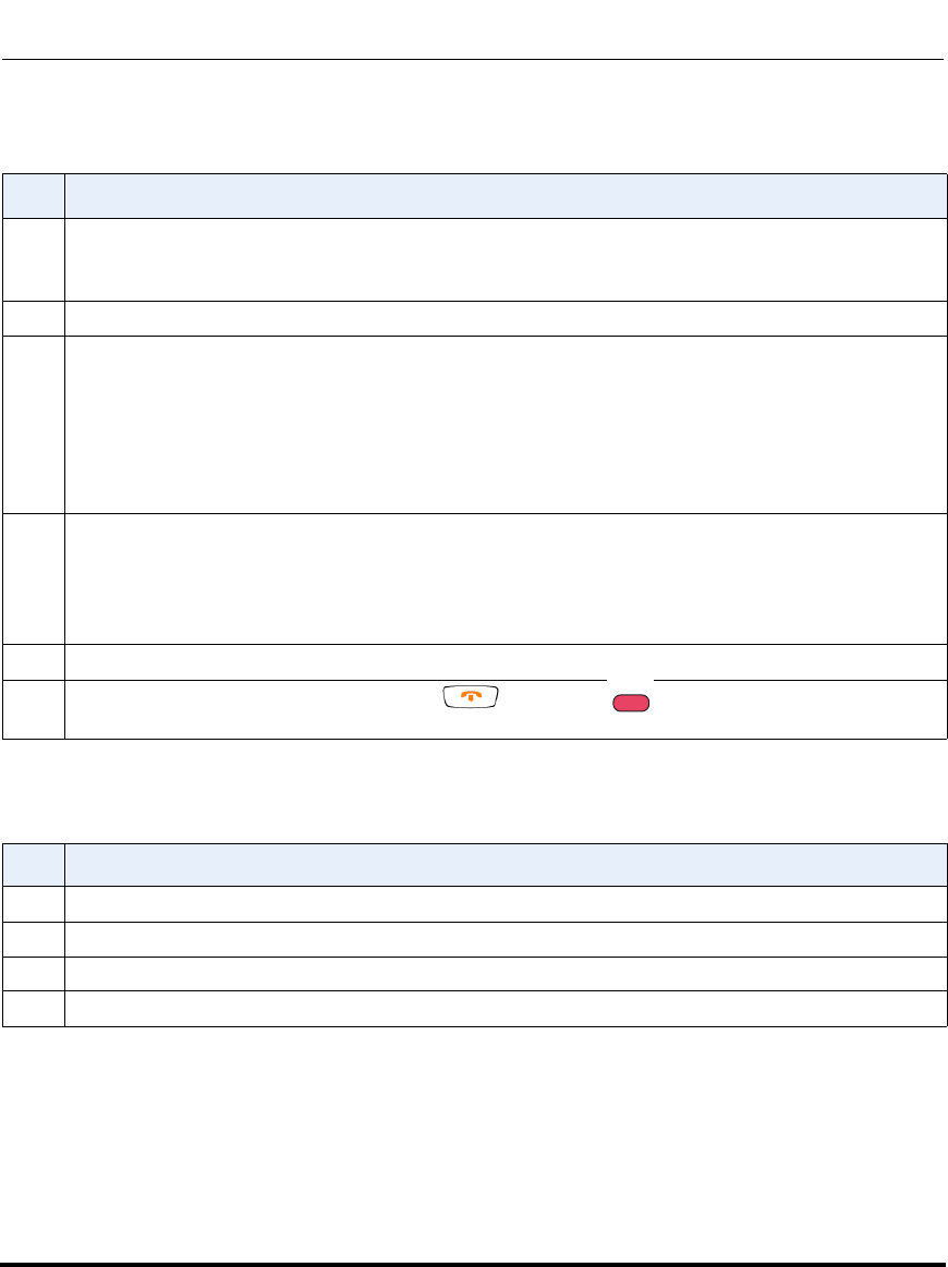
Configuration Methods
41-001160-03, Rev 00, Releaes 2.4 2-5
Configuration Interface Methods
Using the Options Key
From the 9480i CT and 6757i CT handset:
Step Action
1 Press the Options key on the phone to enter the Options List.
Note: Press the Services key on the 6751i and then select Options from the list.
2Use the r and s to scroll through the list of options.
3On 9143i, 6751i, 6753i:
To select an option, press the Enter softkey, or select the number on the keypad that corresponds to
the option in the Option List.
On the 9480i, 9480i CT, 6755i, 6757i, 6757i CT:
To select an option, press the Select softkey, press 4, or select the number on the keypad that
corresponds to the option in the Option List.
4On 9143i, 6751i, 6753i:
Use the Set softkey after making a change to an option, to save the change.
On the 9480i, 9480i CT, 6755i, 6757i, 6757i CT:
Use the Change softkey to change a selected option.
5 Press the Done softkey at any time to save the changes and exit the current option.
6 Press the Cancel softkey, press 3, press , or press any time to exit without saving
changes.
Step Action
1 Press the  key to enter the Options List when the phone is not in use.
2 Use the scroll keys  and Ï to scroll the options.
3 To select and change an option, press the r keys.
4Press y when done.
G
ood
oodbye
Draft 1
Configuration Methods
2-6 41-001160-03, Rev 00, Releaes 2.4
IP Phone Administrator Guide
Aastra Web UI
An administrator can setup and configure the IP phone using the Aastra Web UI.
The Aastra Web UI supports Internet Explorer and Gecko engine-based browsers
like Firefox, Mozilla or Netscape.
HTTP/HTTPS Support
The Aastra Web UI supports both Hypertext Transfer Protocol (HTTP) and
Hypertext Transfer Protocol over Secure Socket Layer (HTTPS) client and server
protocols.
HTTP is the set of rules for transferring files (text, graphic images, sound,
video, and other multimedia files) over the Internet. When you open your
Web browser, you are indirectly making use of HTTP. HTTP is an
application protocol that runs on top of the TCP/IP suite of protocols (the
foundation protocols for the Internet).
HTTPS is a Web protocol that encrypts and decrypts user page requests as well as
the pages that are returned by the Web server. HTTPS uses Secure Socket Layer
(SSL) or Transport Layer Security (TLS) as a sublayer under its regular HTTP
application layering. SSL is a commonly-used protocol for managing the
security of a message transmission on the Internet. It uses a 40-bit key size
for the RC4 stream encryption algorithm, which is considered an adequate degree
of encryption for commercial exchange. TLS is a protocol that ensures privacy
between communicating applications and their users on the Internet. When a
server and client communicate, TLS ensures that no third party may eavesdrop or
tamper with any message. TLS is the successor to SSL.
Note: An Administrator can enable or disable the Aastra Web UI for a
single phone or all phones in a network. For more information about
enabling/disabling the Aastra Web UI, see “Enabling/Disabling the
Aastra Web UI” on page 2-16.
Note: HTTPS uses port 443 instead of HTTP port 80 in its interactions
with the TCP/IP lower layer. Both the HTTP and HTTPS port numbers
are configurable using the configuration files, the IP Phone UI, the Aastra
Web UI and DHCP Option 66. For more information about configuring
these ports, see Chapter 4, the section, “Configuring the Configuration
Server Protocol” on page 4-108.
Draft 1

Configuration Methods
41-001160-03, Rev 00, Releaes 2.4 2-7
Configuration Interface Methods
HTTP/HTTPS Client and Server Support
The Aastra IP phones allow for HTTP request processing and associated data
transfers to perform over a secure connection (HTTPS). The IP phones support
the following:
• Transfer of firmware images, configuration files, script files, and web page
content over a secure connection.
• Web browser phone configuration over a secure connection.
• TLS 1.0or SSL 3.0 methods for both client and server
HTTPS Client
When an HTTPS client opens and closes its TCP socket, the SSL software
respectively handshakes upon opening and disconnects upon closing from the
HTTPS server. The main HTTPS client functions are:
• Downloading of configuration files and firmware images.
• Downloading of script files based on an “HTTPS://” URL supplied by a
softkey definition.
HTTPS Server
The HTTPS server provides HTTP functionality over secure connections. It
coexists with the HTTP server but has its own set of tasks. The main HTTPS
server functions are:
• Delivery of web page content to a browser client over a secure connection.
• Execution of HTTP GET and POST requests received over a secure
connection
Draft 1
Configuration Methods
2-8 41-001160-03, Rev 00, Releaes 2.4
IP Phone Administrator Guide
Non-Blocking HTTP Connections
The IP Phones support a non-blocking HTTP connection feature. This feature
allows the user to continue using the phone when there is a delay during an
HTTP connection while the phone is waiting for the HTTP server to
respond. This feature also allows a user to abort the connection and perform other
operations on the phone (which will abort the HTTP connection automatically). A
user can also abort the HTTP loading by pressing the GOODBYE key while the
phone is displaying “Loading Page.......”.
Authentication Support for HTTP/HTTPS Download Methods for
Broadsoft Client Management System (CMS)
The IP Phones have authentication support per RFC 2617 when using HTTP or
HTTPS as download protocols. If a 5i Series phone is challenged by an HTTP or
HTTPS server when the server attempts to download the aastra.cfg file, the phone
automatically sends "aastra" as the default Username and Password back to the
server. For more information about this feature, see Chapter 5, the section,
“Authentication Support for HTTP/HTTPS Download Methods, used with
Broadsoft Client Management System (CMS)” on page 5-365.
Note: This feature impacts only the HTTP calls triggered by a phone key
(softkey or programmable key); the HTTP calls performed by action
URIs are still blocking.
Draft 1
Configuration Methods
41-001160-03, Rev 00, Releaes 2.4 2-9
Configuration Interface Methods
Using HTTPS via the Aastra Web UI
HTTPS is enabled by default on the IP phones. When you open a browser window
and enter an IP address or host name for a phone using HTTP, a server redirection
occurs which automatically converts an HTTP connection to an HTTPS
connection. After the redirection, a “Security Alert” certificate window displays
alerting the user that information exchanged with the phone cannot be viewed or
changed by others. Accepting the certificate then forwards you to the phone’s Web
UI.
Reference
For more information on configuring the HTTPS protocol, see Chapter 4, the
sections:
•“Configuring the Configuration Server Protocol” on page 4-108
•“HTTPS Client/Server Configuration” on page 4-40
Notes:
1. The private key and certificate generate outside the phone and embed
in the phone firmware for use by the HTTPS server during the SSL
handshake.
2. Using the configuration files, the IP phone UI, or the Aastra Web UI,
you can configure the following regarding HTTPS:
- Specify HTTPS security client method to use (TLS 1.0 or SSL 3.0)
- Enable or disable HTTP to HTTPS server redirect function
- HTTPS server blocking of XML HTTP POSTS to the phone
Draft 1
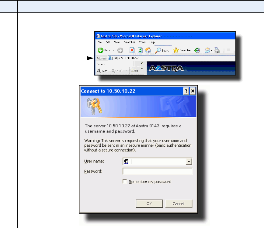
Accessing the Aastra Web UI
Use the following procedure to access the Aastra Web UI.
Step Action
1 Open your web browser and enter the phone’s IP address or host name into the address field.
The following is an example of the Login screen that displays.
IP address or
host name
Draft 1
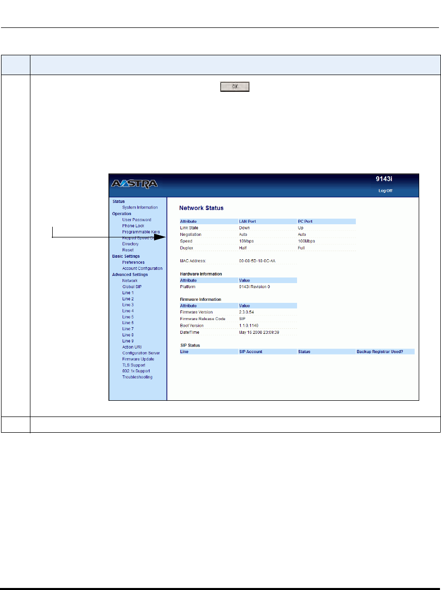
Configuration Methods
41-001160-03, Rev 00, Releaes 2.4 2-11
Configuration Interface Methods
2 Enter your username and password and click .
Note: For an administrator, the default username is “admin” and the password is “22222”.
For a user, the default username is “user” and the password field is left blank.
The IP phones accept numeric passwords only.
The Network Status window displays for the IP phone you are accessing. The following illustration is
an example of a Network Status screen for the 9143i IP phone.
3 You can logout of the Aastra Web UI at any time by clicking LOGOFF.
Step Action
9143i Network
Status Window
Draft 1
Configuration Methods
2-12 41-001160-03, Rev 00, Releaes 2.4
IP Phone Administrator Guide
Depending on the model phone you are accessing, the following categories
display in the side menu of the Aastra Web UI: Status, Operation, Basic
Settings, Advanced Settings.
Status
The Status section displays the network status and the MAC address of the IP
phone. It also displays hardware and firmware information about the IP phone.
The status window also displays the SIP Account information for each account on
the phone. The information in the Network Status window is read-only.
Operation
The Operation section provides the following options:
Note: Programmable Keys apply to the 9143i, 6753i, and 6755i. Softkeys
apply to the 9480i, 9480i CT, 6755i, 6757i, and 6757i CT. Expansion
Modules apply to the 6753i, 6755i, 6757i, and 6757i CT only.
Heading Description
User Password Allows you to change user password.
(Applicable to User and Administrator).
Phone Lock Allows you to assign an emergency dial plan to the phone,
lock the phone to prevent any changes to the phone and to
prevent use of the phone, and reset the user password.
Note: You can also configure a softkey to use for locking/
unlocking the phone.
(Applicable to User and Administrator).
Programmable Keys 9143i - 7 multi-functional programmable keys
6753i - 6 Top, multi-functional, programmable keys
6755i - 6 Top multi-functional, programmable keys
(Applicable to User and Administrator).
Draft 1

Configuration Methods
41-001160-03, Rev 00, Releaes 2.4 2-13
Configuration Interface Methods
Softkeys and XML 9480i/9480i CT6 state-based, multi-functional softkeys
6755i 6 Bottom, state-based, multi-functional
softkeys
6757i/6757i CT6 Top, multi-functional, static softkeys
6 Bottom, state-based, multi-functional
softkeys
(Applicable to User and Administrator).
Expansion Module <N> The M670i has up to 36 configurable keys. The M675i has
up to 60 configurable keys. You can have up to 3 expansion
modules attached to a single phone allowing you to
configure keys for Expansion Module 1, Expansion Module
2, and Expansion Module 3.See your Model-specific User
Guide for applicable expansion modules for your model
phone.
Note: Expansion Modules apply to the 6753i, 6755i, 6757i,
and 6757i CT only.
(Applicable to User and Administrator).
Handset Keys
(9480i CT and 6757i CT
only)
Allows you to configure up to 15 softkeys on the handset.
(Applicable to User and Administrator).
Keypad Speed Dial Allows you to configure up to 9 speeddial keys. These fields
map to the keypad digits 1 through 9 on the phone. You can
also configure additional speeddials on the programmable
keys, softkeys and expansion modules. See your
model-specific User Guide for more information about this
feature.
(Applicable to User and Administrator).
Directory Allows you to copy the Callers List and Directory List from
your IP phone to your PC.
(Applicable to User and Administrator).
Reset Allows you to restart the IP phone when required.
(Applicable to User and Administrator).
This setting also allows you to set the IP phone back to its
factory default settings or remove the local configuration.
(Applicable Administrator only).
Heading Description
Draft 1

Configuration Methods
2-14 41-001160-03, Rev 00, Releaes 2.4
IP Phone Administrator Guide
Basic Settings
The Basic Settings section provides the following options:
Heading Description
Preferences Allows you to set the following General specifications on the
IP phone.
• Local Dial Plan (Admin Only)
• Send Dial Plan Terminator (Admin Only)
• Digit Timeout (Admin Only)
• Park Call (not available on 9143i and 6753i)
• Pickup Parked Call (not available on 9143i and 6753i)
• Suppress DTMF Playback
• Display DTMF Digits
• Call Waiting
• Play Call Waiting Tone
• Stuttered Dial Tone
• XML Beep Support
• Status Scroll Delay
• Incoming Call Interrupts Dialing
• Switch Focus to Ringing Line
• Preferred Line
• Preferred Line Timeout (seconds)
• Goodbye Key Cancels Incoming Call
• UPnP Mapping Lines
• Message Waiting Indicator Line
• DND Key Mode
• Call Forward Key Mode
• Use LLDP ELIN
This section also allows you to set:
• Incoming Intercom Settings
• Outgoing Intercom Settings (Admin Only; Administrator
can enable these for a User if required)
• Group Paging RTP Settings
• Key Mapping (Admin Only)
• Ring Tones
• Priority Alert Settings (Admin Only)
• Directed Call Pickup Settings (Admin Only)
• Auto Call Distribution Settings (Admin Only)
• Time and Date Settings
• Language Settings (Only the Admin can specify the
language pack names to load to the phone). Both the
Admin and User can select the language type to display
for the Web UI.
Account Configuration Allows you to configure DND (Do Not Disturb) and/or Call
Forwarding by specific account or by all accounts. Also
allows you to enable/disable specific states for each
account, specify different phone numbers for call
forwarding, and specify number of rings for a “No Answer”
state.
Draft 1

Configuration Methods
41-001160-03, Rev 00, Releaes 2.4 2-15
Configuration Interface Methods
Advanced Settings (Applicable to Administrator Only)
The Advanced Settings section provides the following options:
Heading Description
Network Allows you to set Basic Network Settings, Advanced
Network Settings, Type of Service DSCP, and VLAN
settings.
Global SIP Allows you to set global Basic SIP Authentication Settings,
Basic SIP Network Settings, Advanced SIP Settings,
Real-time Transport Protocol (RTP) settings, and Autodial
Settings that apply to all lines on the IP phone.
Lines 1 through 9 Allows you to set per-line Basic SIP Authentication Settings,
Basic SIP Network Settings, Advanced SIP Settings,
Real-time Transport Protocol (RTP) settings, and Autodial
Settings that apply to specific lines on the IP phone.
Action URI Allows an administrator to specify a uniform resource
identifier (URI) that triggers a GET when certain events
occur. An Administrator can also specify a URI to be called,
enable polling for the URI, and specify the interval between
polls.
(Applicable to Administrator Only)
Configuration Server Allows you to set the protocol to use on the configuration
server (TFTP (default), FTP, HTTP, or HTTPS), configure
automatic firmware and configuration file updates, enable/
disable auto-resync, and assign an XML push server list.
(Applicable to Administrator Only)
Firmware Update Allows you to manually perform a firmware update on the IP
phone from the configuration server using any of the IP
Phones supported protocols.
(Applicable to Administrator Only)
TLS Support Allows you to specify the SIP Root and Intermediate
Certificate files to use when the phone uses the TLS
transport protocol to setup a call.
(Applicable to Administrator Only)
Draft 1
Configuration Methods
2-16 41-001160-03, Rev 00, Releaes 2.4
IP Phone Administrator Guide
Enabling/Disabling the Aastra Web UI
The Aastra Web UI is enabled by default on the IP phones. A System
Administrator can disable the Aastra Web UI on a single phone or on all phones if
required using the configuration files. Use the following procedure to enable and
disable the Aastra Web UI.
To disable the Aastra Web UI:
802.1x Support Allows you to enable/disable the 802.1x Protocol
(Extensible Authentication Protocol (EAP)) to use on the IP
phones for authentication purposes. Applicable choices are
EAP-MD5 or EAP-TLS.
(Applicable to Administrator Only)
Troubleshooting Allows you to perform troubleshooting tasks whereby the
results can be forwarded to Aastra Technical Support for
analyzing and troubleshooting.
(Applicable to Administrator Only)
Configuration Files
Step Action
1 Using a text-based editing application, open the <mac>.cfg file if you want to disable the Web UI on a
single phone. Open the aastra.cfg file to disable the Web UI on all phones
2 Enter the following parameter:
web interface enabled: 0
Note: A value of zero (0) disables the Web UI on the phone. A value of 1 enables the Web UI.
3 Save the changes and close the <mac>.cfg or the aastra.cfg file.
4 Restart the phone to apply the changes. The Aastra Web UI is disabled for a single IP phone or for all
phones.
Heading Description
Draft 1
Configuration Methods
41-001160-03, Rev 00, Releaes 2.4 2-17
Configuration Interface Methods
Configuration Files (Administrator Only)
A system administrator can enter specific parameters in the configuration files to
configure the IP phones. All parameters in configuration files can only be set by
an administrator.
You can enter specific configuration parameters in either of the following
configuration files:
• aastra.cfg
•<mac>.cfg
References
For information about configuration file precedence, see Chapter 1, “Overview.”
For a description of each configuration file parameter, see Appendix A,
“Configuration Parameters.”
Using the Configuration Files
When you use the configuration files to configure the IP phones, you must use a
text-based editing application to open the configuration file (aastra.cfg or
<mac>.cfg).
Use the following procedure to add, delete, or change parameters and their
settings in the configuration files.
Note: Apply this procedure wherever this Administrator Guide refers to
configuring parameters using the configuration files.
Draft 1
Locking Parameters in the Configuration File
The IP Phones allow you to lock individual configuration parameters to prevent
an end user from changing the configuration on the phone. This feature allows
service providers to prevent the end-user from changing the values of specific
parameters that would affect the service they provide.
An Administrator can lock parameters on the phone by placing an exclamation
mark (!) before the parameter in the configuration file. For example,
!admin password: 22222
!emergency dial plan: 911|999
You can lock parameters on the phone using the configuration files only. Once the
parameters are locked, they cannot be changed at all during the phones run-time.
The parameters appear as read-only when accessing the Aastra Web UI and the IP
Phone UI. In the Aastra Web UI, they appear grayed out. In the IP Phone UI the
ability to change the parameters is removed. In addition, when parameters are
locked, they cannot be changed via XML.
Configuration files
Step Action
1 Using a text-based editing application, open the configuration file for the phone, for which you want to
configure the directory list (either aastra.cfg, <mac>.cfg or both).
2 Enter the required configuration parameters followed by the applicable value. For example,
directory 1: company_directory
directory 2: my_personal_directory
3 Save the changes and close the configuration file.
4 If the parameter requires the phone to be restarted in order for it to take affect, use the
IP Phone UI or the Aastra Web UI to restart the phone.
Draft 1

Configuration Methods
41-001160-03, Rev 00, Releaes 2.4 2-19
Configuration Interface Methods
Limitations
• A User possessing the Administrator password can bypass the locking of
configuration server details by defaulting the phone.
• Parameters cannot be locked using XML.
• Configuration files that include locked parameters are not backwards
compatible
Notes:
1. The “parameter locking” feature applies to Release 2.4 and up. Any
phones that have a previous release loaded on the phone will not be able
to use the locking functionality in the configuration file.
2. Any parameter duplicated in the mac.cfg from the aastra.cfg is
overwritten by the locking status and the value of the parameter found in
the mac.cfg file.
Draft 1
Draft 1
41-001160-03, Rev 00, Releaes 2.4 3-1
Chapter 3
Administrator Options
About this chapter
Introduction
The IP phones provide specific options on the IP Phone that only an Administrator
can access. These options are password protected and allow an Administrator to
change or set features and configuration information as required. For all models,
an Administrator can use the IP Phone UI, the Aastra Web UI, or the configuration
files to enter and change values.
This chapter provides information about the available Administrator options.
Topics
This chapter covers the following topics:
Note: Specific options are configurable only via the IP Phone UI, and/or
Aastra Web UI, and/or configuration files.
Topic Page
Administrator Level Options page 3-3
IP Phone UI Options page 3-3
Aastra Web UI Options page 3-6
Configuration File Options page 3-8
Phone Status page 3-9
Restarting Your Phone page 3-13
Draft 1
About this chapter
3-2 41-001160-03, Rev 00, Releaes 2.4
IP Phone Administrator Guide
Set Phone to Factory Defaults/Erase Local Configuration page 3-15
Basic Settings page 3-19
Account Configuration page 3-35
Network Settings page 3-37
Line Settings page 3-71
Softkeys, Programmable Keys, Expansion Module Keys page 3-72
Action URI page 3-73
Configuration Server Settings page 3-75
Firmware Update Features page 3-84
TLS Support page 3-85
802.1x Support page 3-89
Troubleshooting page 3-92
Topic Page
Draft 1
Administrator Level Options
41-001160-03, Rev 00, Releaes 2.4 3-3
Administrator Options
Administrator Level Options
Description
There are options on the IP phone that both a User and Administrator can access.
However, there are specific options that an Administrator can access only. These
options allow the Administrator to configure and manage local and/or remote IP
phones in a network.
An Administrator can access and manage these options using the IP Phone UI, the
Aastra Web UI, or the configuration files.
IP Phone UI Options
Using the IP Phone UI, you can access the Administrator options at
Options->Administrator Menu using the default password of "22222"
Note: An administrator has the option of enabling and disabling the use
of password protection in the IP phone UI. This is configurable using the
configuration files only. For more information about this feature, see
Appendix A, the section “Password Settings” on page A-15
Options Menu
Select
Done
1. Call Forward
2. Preferences
3. Phone Status
4. User Password
5. Administrator Menu
6. Restart Phone
7. Phone Lock
Administrator Menu
Draft 1

Administrator Level Options
3-4 41-001160-03, Rev 00, Releaes 2.4
IP Phone Administrator Guide
The following are administrator options in the "Options List" on the IP phone UI:
• Administrator Menu
— Configuration Server
— Network Settings
— SIP Settings
— Factory Default
— Erase Local Config.
References
For information about all other user options in the “Options Menu”, see your
model-specific SIP IP Phone User Guide.
For procedures on configuring Administrator Options on the IP phone via the IP
phone UI, see:
Chapter 4, “Configuring Network and Session Initiation Protocol (SIP) Features”
Chapter 5, “Configuring Operational Features”
Chapter 6, “Configuring Advanced Operational Features”
Draft 1
Administrator Level Options
41-001160-03, Rev 00, Releaes 2.4 3-5
Administrator Options
Simplified IP Phone UI Options Menu
An Administrator can replace the existing options menu on the Phone UI with a
more simplified options menu. In the configuration files, the “options simple
menu” parameter allows you to display either the full menu (if set to 0), or the
simplified menu (if set to 1). The following table illustrates the differences
between the full menu and the simplified menu.
When setting the “options simple menu” parameter, the menu changes in the
Phone UI only. The Aastra Web UI is not affected.
Configuring the Simplified IP Phone UI Options Menu
You can enable the simplified IP Phone UI Options menu using the configurations
files only.
Full Options Menu Simplified Options Menu
Call Forward Call Forward
Preferences Preferences
Phone Status Phone Status
User Password Removed
Administrator Menu Removed
Restart Phone Removed
Phone Lock Phone Lock
Warning: When using the simplified menu, you cannot change the
Network settings from the IP Phone UI. If the network settings become
misconfigured, you must “factory default” the phone and use the full
menu to recover the network settings from the Phone UI OR use the
Aastra Web UI to configure the network settings.
Configuration Files
For the specific parameter you can set in the configuration files, see Appendix A, the section, “Simplified IP
Phone UI Options Menu” on page A-7.
Draft 1
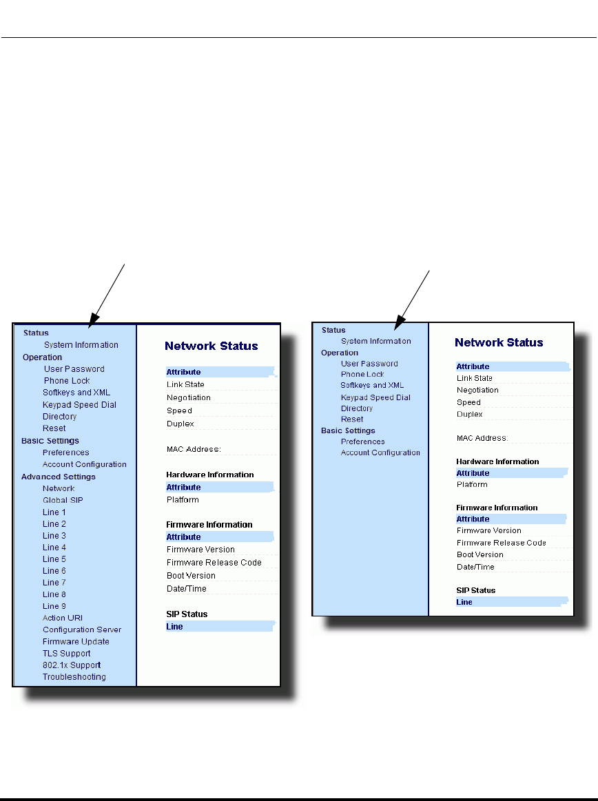
Administrator Level Options
3-6 41-001160-03, Rev 00, Releaes 2.4
IP Phone Administrator Guide
Aastra Web UI Options
An Administrator can configure specific options using the Aastra Web UI. These
options display after an Administrator logs into the Web UI using a Web browser
and entering the Admin username and password at the login prompt (The default
username is "admin" and the default password is "22222". The IP phones accept
numeric passwords only.) The column on the left side of the screen indicates the
configurable options. A User has limited configuration options as shown in the
following illustrations.
Administrator Web UI Menu User Web UI Menu
Draft 1

Administrator Level Options
41-001160-03, Rev 00, Releaes 2.4 3-7
Administrator Options
The following are options that an Administrator can configure in the Aastra Web
UI (and are not available for the User to configure):
• Operation->Reset
— Restore to Factory Defaults
— Remove Local Configuration Settings
• Basic Settings->Preferences->General
— Local Dial Plan
— Send Dial Plan Terminator
— Digit Timeout (seconds)
• Basic Settings->Preferences->Outgoing Intercom Settings (User can
configure this via the Aastra Web UI if enabled by an Administrator)
• Basic Settings->Preferences->Key Mapping
• Basic Settings->Preferences->Priority Alerting Settings
• Basic Settings->Preferences->Directed Call Pickup Settings
• Basic Settings->Preferences->Auto Call Distribution Settings
• Basic Settings->Preferences->Language Settings
— Language 1 (entering language pack filename)
— Language 2 (entering language pack filename)
— Language 3 (entering language pack filename)
— Language 4 (entering language pack filename)
• Advanced Settings
—Network
— Global SIP
— Line 1 through 9 Settings
— Action URI
— Configuration Server
— Firmware Update
— TLS Support
— 802.1x Support
— Troubleshooting
Draft 1

Administrator Level Options
3-8 41-001160-03, Rev 00, Releaes 2.4
IP Phone Administrator Guide
References
For information about options available to a User AND Administrator in the
Aastra Web UI, see your Model-specific User Guide.
For procedures to Restart your phone or restore factory defaults, see “Restarting
Your Phone” on page 3-13, and “Set Phone to Factory Defaults/Erase Local
Configuration” on page 3-15.
For more information about Advanced Settings for the IP Phone, see Chapter 4,
“Configuring Network and Session Initiation Protocol (SIP) Features.”
For procedures on configuring the Basic Settings for the IP Phone, see Chapter 5,
“Configuring Operational Features.”
Configuration File Options
An Administrator can enter specific parameters in the configuration files to
configure the IP phones. All parameters in configuration files can only be set by
an administrator.
References
For a procedure on using the configuration files, see Chapter 2, the section,
“Configuration Files (Administrator Only)” on page 2-1.
For a description of each parameter you can enter in the configuration files, see
Appendix A, “Configuration Parameters.”
Draft 1
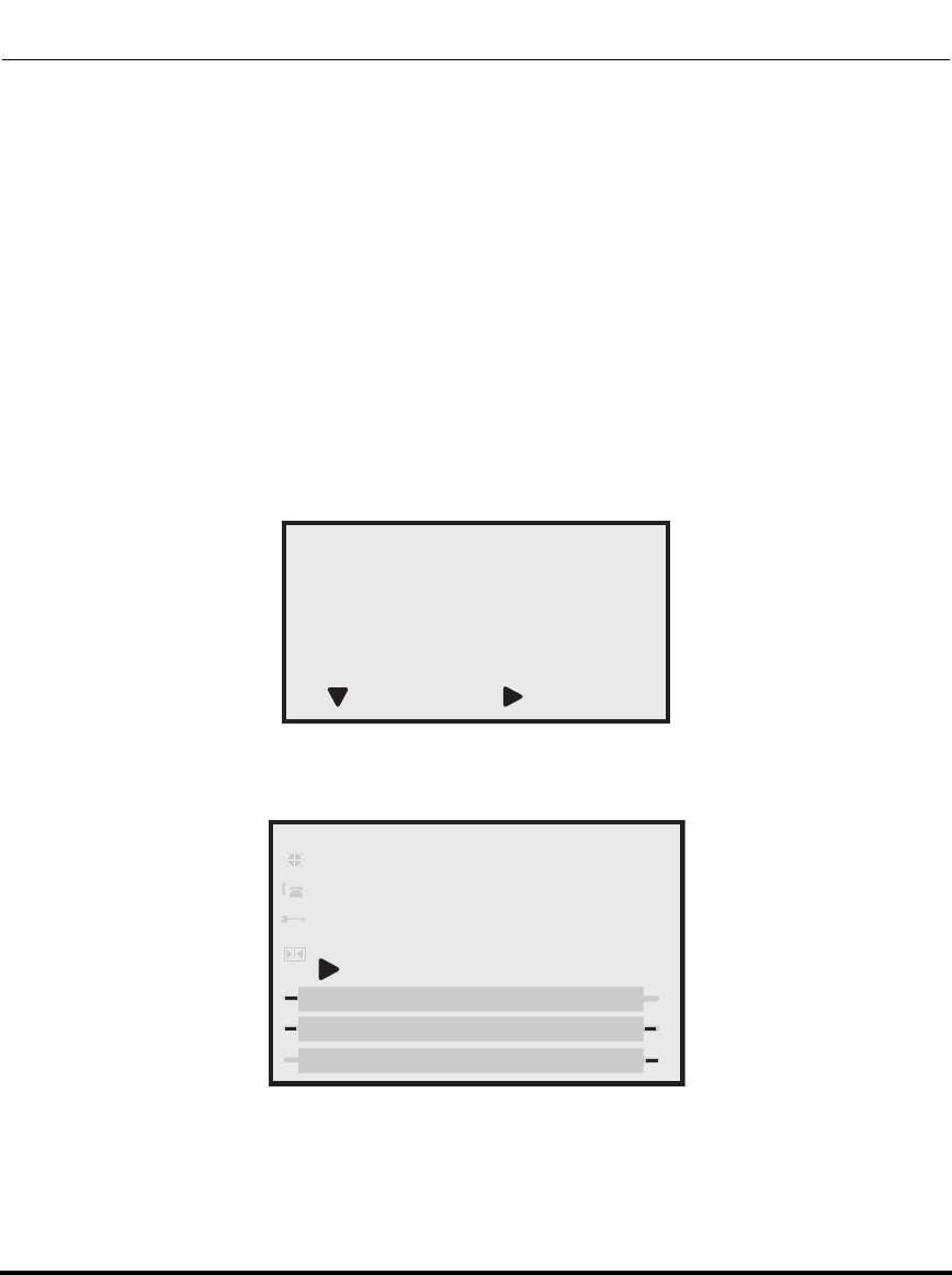
Administrator Level Options
41-001160-03, Rev 00, Releaes 2.4 3-9
Administrator Options
Phone Status
The Phone Status on the IP Phone displays the network status and firmware
version of the IP phone.
You can display phone status using the IP phone UI or the Aastra Web UI.
Phone Status via IP Phone UI
In the IP phone UI, the Phone Status options are available to the user and the
administrator and do not require a password entry.
The following options display for phone status on the IP phone UI:
Phone Status Screen for 9143i, 6751i, 6753i Phones
Phone Status Screen for 9480i, 9480i CT, 6755i, 6757i, 6757i CT
Phones
Phone Status
1. IP&MAC Addresses
2. LAN Port
3. PC Port
4. Firmware Info
=Enter
=Next
Phone Status
Select
Done
1. IP&MAC Addresses
2. LAN Port
3. PC Port
4. Firmware Info
Draft 1
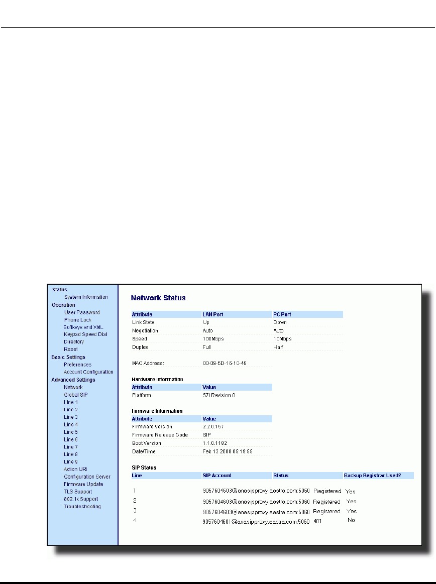
Administrator Level Options
3-10 41-001160-03, Rev 00, Releaes 2.4
IP Phone Administrator Guide
• IP&MAC Addresses
Displays the IP address and MAC address of the phone.
• LAN Port
Displays the Link State, Negotiation Method, Speed, and Duplex Method that
the phone uses on its LAN port.
•PC Port
Displays the Link State, Negotiation Method, Speed, and Duplex Method that
the phone uses on its PC Port.
•Firmware Info
Displays information about the firmware that is currently installed on the IP
phone.
Phone Status via Aastra Web UI
The first screen that displays after logging into the Aastra Web UI for a phone is
the Network Status screen. This screen also displays when selecting
Status->System Information. The information on this screen is available to the
user and the administrator as read-only.
Draft 1

Administrator Level Options
41-001160-03, Rev 00, Releaes 2.4 3-11
Administrator Options
The following is a description of the information on the Network Status screen:
•Network Attributes
Displays the network status of the Ethernet ports at the back of the phone. You
can also view the phone’s IP and MAC addresses. Information in this field
includes Link State, Negotiation, Speed, and Duplex for Port 0 and Port 1.
•Hardware Information
Displays the current IP phone platform and the revision number.
•Firmware Information
Displays information about the firmware that is currently installed on the IP
phone. Information in this field includes Firmware Version, Firmware Release
Code, Boot Version, Release Date/Time.
•SIP Status
Displays information about the SIP registration status of the phone. If there
are accounts configured on the IP Phone, their SIP status displays in this field.
The 6751i displays only one status line. All other model phones display the
status of up to 9 lines.
Draft 1

Administrator Level Options
3-12 41-001160-03, Rev 00, Releaes 2.4
IP Phone Administrator Guide
The following table describes the status conditions that can display for an
account(s).
Status Condition Description
Registered Displays this status on accounts that HAVE been registered with the SIP proxy
server.
Example: Backup
Registrar
Line SIP Account Status Used?
1 9057604603@anasipproxy.aastra.com:5060Registered Yes
where
Account Number is “1”
SIP Account is “9057604603@anasipproxy.aastra.com” on port “5060”
Status is “Registered”
Backup registrar is used (“Yes”)
SIP Error Number Displays on accounts when registration fails with the SIP proxy server.
Example:Backup
Registrar
Line SIP Account Status Used?
4 9057604601@anasipproxy.aastra.com:5060401 No
where
Account Number is “4”
SIP Account is “9057604601@anasipproxy.aastra.com” on port “5060”
Status is “401” - Unregistered if SIP registration fails.
Backup registrar is used (“No”)
Note: The IP Phones can register with multiple server using the same
user name. So the SIP Status information on the Network Status screen
may display the same account with different registrar and proxy IP
addresses. For more information, see
Draft 1
Administrator Level Options
41-001160-03, Rev 00, Releaes 2.4 3-13
Administrator Options
Restarting Your Phone
As System Administrator, there may be times when you need to restart a phone.
The Restart option allows you reboot the phone when required. A reset may be
necessary when:
• There is a change in your network, OR
• To re-load modified configuration files, OR
• If the settings for the IP phone on the IP PBX system have been modified.
You can restart the phone using the IP Phone UI or the Aastra Web UI.
Restarting the Phone Using the IP Phone UI
IP Phone UI
Step Action
1 Press the Options key on the phone to enter the Options List.
2Select Restart Phone.
3For 9143i. 6751i, 6753i:
Press # to confirm.
Note: To cancel the Restart, press the 3 key.
For 9480i, 9480i CT, 6755i, 6757i, 6757i CT:
Press Restart.
Note: To cancel the Restart, press Cancel.
Draft 1
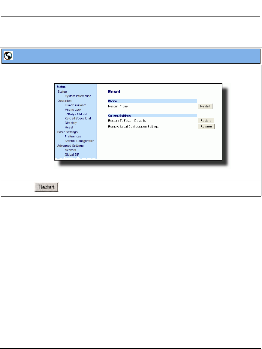
Administrator Level Options
3-14 41-001160-03, Rev 00, Releaes 2.4
IP Phone Administrator Guide
Restarting the Phone Using the Aastra Web UI
Aastra Web UI
1 Click on Operation->Reset->Phone.
2 Click to restart the phone.
Draft 1
Administrator Level Options
41-001160-03, Rev 00, Releaes 2.4 3-15
Administrator Options
Set Phone to Factory Defaults/Erase Local Configuration
You can set phones to their factory default setting or remove a local phone’s
configuration using the IP Phone UI or the Aastra Web UI.
Setting Factory Defaults on the Phone
Factory default settings are the settings that reside on the phone after it has left the
factory. The factory default settings on the phone sets the factory defaults for all
of the settings in the aastra.cfg, <mac>.cfg, and local configuration. Performing
this action results in losing all user-modified settings.You can reset a phone to
factory defaults using the IP Phone UI or the Aastra Web UI.
Setting Factory Defaults Using the IP Phone UI
IP Phone UI
Step Action
1 Press the Options key on the phone to enter the Options List.
2Select Administrator Menu and enter your Administrator Password (default is 22222).
3Select Factory Default.
4For 9143i, 6751i, 6753i:
The “Restore Defaults?” prompt displays.
Press # to confirm.
For 9480i, 9480i CT, 6755i/6757i/6757i CT:
The “Reset phone to factory defaults?” prompt displays.
Press Default to confirm.
Draft 1
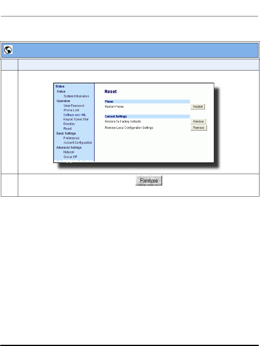
Administrator Level Options
3-16 41-001160-03, Rev 00, Releaes 2.4
IP Phone Administrator Guide
Settings Factory Defaults Using the Aastra Web UI
Aastra Web UI
Step Action
1 Click on Operation->Reset->Current Settings.
2 In the "Restore to Factory Defaults" field, click .
This restores all factory defaults, and removes any saved configuration and directory list files.
Draft 1
Administrator Level Options
41-001160-03, Rev 00, Releaes 2.4 3-17
Administrator Options
Erasing the Phone’s Local Configuration
You can reset the IP Phone’s local configuration if required. The local
configuration is the last updated configuration you performed using the IP Phone
UI or the Aastra Web UI. Performing this action results in losing all recently
user-modified settings. For more information about local configuration, see
Chapter 1, the section, “Configuration File Precedence” on page 1-38.
Erasing the Phone’s Local Configuration Using the IP Phone UI
IP Phone UI
Step Action
1 Press the Options key on the phone to enter the Options List.
2Select Administrator Menu and enter your Administrator Password (default is 22222).
3Select Erase Local Config.
4For 9143i, 6751i, 6753i:
The “Erase local config?” prompt displays.
Press # to confirm.
For 9480i, 9480i CT, 6755i, 6757i, 6757i CT:
The “Erase local config?” prompt displays.
Press Erase to confirm.
Draft 1
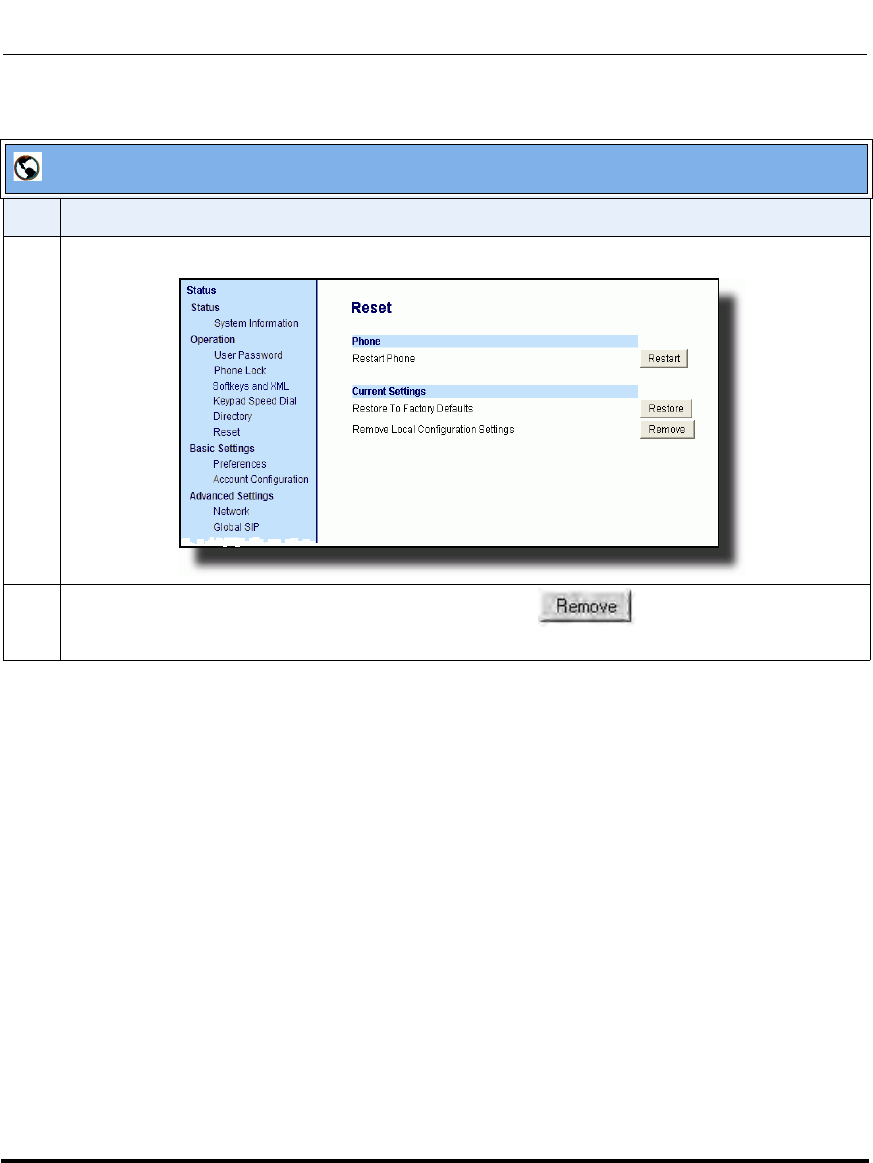
Administrator Level Options
3-18 41-001160-03, Rev 00, Releaes 2.4
IP Phone Administrator Guide
Erasing the Phone’s Local Configuration Using the Aastra Web UII
Aastra Web UI
Step Action
1 Click on Operation->Reset->Current Settings.
2 In the "Remove Local Configuration Settings" field, click .
This removes the last customized configuration settings made on the phone.
Draft 1

Administrator Level Options
41-001160-03, Rev 00, Releaes 2.4 3-19
Administrator Options
Basic Settings
An Administrator has access to specific Basic Setting options to configure and
manage the IP Phone in the network. The following sections identify the options
available to an Administrator only, or where indicated, to a User and
Administrator. These tables also identify whether you can configure them using
the Aastra Web UI, IP Phone UI, or the configuration files.
General Settings
Parameter in
Aastra Web UI Parameter in
Configuration Files Description
Local Dial Plan sip dial plan A dial plan that describes the number and pattern of
digits that a user dials to reach a particular telephone
number. Dial Plan field accepts up to 512 characters.
For more information on this feature, see “Local Dial
Plan” on page 5-53.
Send Dial Plan
Terminator sip dial plan terminator Allows you to enable or disable a dial plan terminator.
When you configure the dial plan on the phone to use
a dial plan terminator (such as the pound symbol (#)),
the phone waits 4 or 5 seconds after you pick up the
handset or after dialing the number on the keypad
before making the call.
For more information on this feature, see “SIP Dial
Plan Terminator” on page 5-55.
Digit Timeout sip digit timeout Represents the time, in seconds, to configure the
timeout between consecutive key presses.
For more information on this feature, see. “Digit
Timeout” on page 5-55.
Draft 1

Administrator Level Options
3-20 41-001160-03, Rev 00, Releaes 2.4
IP Phone Administrator Guide
Park Call
Note: This option can
be set by both Users
and Administrators.
sprecode The parking of a live call to a specific extension.
This feature on the Basic Preferences screen is
available on the 9480i, 9480i CT, 6755i, 6757i, and
6757i CT only.
To configure the Park feature on a global basis, see
Chapter 5, the section, “Park Calls/Pick Up Parked
Calls” on page 5-59.
To configure the Park feature on a key, see Chapter 5,
the section, “Park/Pick Up Key” on page 5-234.
Pick Up Parked Call
Note: This option can
be set by both Users
and Administrators.
pickupsprecode Picking up a parked call at the specified extension.
This feature on the Basic Preferences screen is
available on the 9480i, 9480i CT, 6755i, 6757i, and
6757i CT only.
To configure the Pickup feature on a global basis, see
Chapter 5, the section, “Park Calls/Pick Up Parked
Calls” on page 5-59.
To configure the Pickup feature on a key, see Chapter
5, the section, “Park/Pick Up Key” on page 5-234.
Suppress DTMF
Playback
Note: This option can
be set by both Users
and Administrators.
suppress dtmf playback Enables and disables suppression of DTMF playback
when a number is dialed from the softkeys or
programmable keys.
For more information on this feature, see.
“Suppressing DTMF Playback” on page 5-63.
Display DTMF Digits
Note: This option can
be set by both Users
and Administrators.
display dtmf digits Enables and disables the display of DTMF digits on
the IP phone display during a connected state.
For more information on this feature, see. “Display
DTMF Digits” on page 5-65.
Call Waiting
Note: This option can
be set by both Users
and Administrators.
call waiting Enable or disables Call Waiting on the IP Phone.
For more information on this feature, see. “Call
Waiting/Call Waiting Tone” on page 5-67.
Parameter in
Aastra Web UI Parameter in
Configuration Files Description
Draft 1

Administrator Level Options
41-001160-03, Rev 00, Releaes 2.4 3-21
Administrator Options
Play Call Waiting Tone
Note: This option can
be set by both Users
and Administrators.
call waiting tone Enable or disables the playing of a call waiting tone
when a caller is on an active call and a new call comes
into the phone.
For more information on this feature, see. “Call
Waiting/Call Waiting Tone” on page 5-67.
Stuttered Dial Tone
Note: This option can
be set by both Users
and Administrators.
stutter disabled Enable or disables the playing of a stuttered dial tone
when there is a message waiting on the IP phone.
For more information on this feature, see. “Stuttered
Dial Tone” on page 5-70.
XML Beep Support
Note: This option can
be set by both Users
and Administrators.
xml beep notification Enables or disables the playing of a beep to indicate a
status on the phone. When the phone receives a
status message, the BEEP notifies the user that the
message is displaying.
For more information on this feature, see “XML Beep
Support” on page 5-72.
Status Scroll Delay
(seconds)
Note: This option can
be set by both Users
and Administrators.
xml status scroll delay Allows you to set the time delay, in seconds, between
the scrolling of each status message on the phone.
For more information on this feature, see “Status
Scroll Delay” on page 5-74.
Incoming Call Interrupts
Dialing
Note: This option can
be set by both Users
and Administrators.
incoming call interrupts
dialing Enable or disables how the phone handles incoming
calls while the phone is dialing out. For more
information on this feature, see “Incoming Call
Interrupts Dialing” on page 5-76.
Switch Focus to Ringing
Line
Note: This option can
be set by both Users
and Administrators.
switch focus to ringing
line Enables or disables whether or not the UI focus is
switched to a ringing line while the phone is in the
connected state.
For more information on this feature, see “Switch
Focus to Ringing Line” on page 5-79.
Preferred Line
Note: This option can
be set by both Users
and Administrators.
preferred line Specifies the preferred line to switch focus back to
when incoming or outgoing calls end on the phone.
For more information on this feature, see “Preferred
Line and Preferred Line Timeout” on page 5-81.
Parameter in
Aastra Web UI Parameter in
Configuration Files Description
Draft 1

Administrator Level Options
3-22 41-001160-03, Rev 00, Releaes 2.4
IP Phone Administrator Guide
Preferred Line Timeout
(seconds)
Note: This option can
be set by both Users
and Administrators.
preferred line timeout Specifies the time, in seconds, that the phone
switches back to the preferred line after a call
(incoming or outgoing) ends on the phone, or after a
duration of inactivity on an active line.
For more information on this feature, see “Preferred
Line and Preferred Line Timeout” on page 5-81.
Goodbye Key Cancels
Incoming Call
Note: This option can
be set by both Users
and Administrators.
goodbye key cancels
incoming call Enable or disables the behavior of the Goodbye Key
on the IP phone.
For more information on this feature, see “Goodbye
Key Cancels Incoming Call” on page 5-85.
UPnP Mapping Lines
Note: This option can
be set by both Users
and Administrators.
upnp mapping lines Enables or disables the use of Universal Plug and
Play (UpnP) on a specific line on the IP phone.
For more information on this feature, see “UPnP
Mapping Lines (for remote phones)” on page 5-87.
Message Waiting
Indicator Line
Note: This option can
be set by both Users
and Administrators.
mwi led line Allows you to enable the Message Waiting Indicator
(MWI) on a single line or on all lines on the phone. For
example, if you set this parameter to 3, the LED
illuminates if a voice mail is pending on line 3. If you
set this parameter to 0, the LED illuminates if a voice
mail is pending on any line on the phone (lines 1
through 9).
For more information on this feature, see “Message
Waiting Indicator Line” on page 5-89.
DND Key Mode
Note: This option can
be set by both Users
and Administrators.
dnd key mode Allows you to configure the DND mode to use on the
phone (Account, Phone, Custom) when the DND key
is pressed. You can configure DND for all accounts or
a specific account.
For more information on this feature, see “DND Key
Mode” on page 5-91. Also see Chapter 5, the section,
“Do Not Disturb (DND)” on page 5-211.
Parameter in
Aastra Web UI Parameter in
Configuration Files Description
Draft 1

Administrator Level Options
41-001160-03, Rev 00, Releaes 2.4 3-23
Administrator Options
Call Forward Key Mode
Note: This option can
be set by both Users
and Administrators.
call forward key mode Allows you to configure the Call Forward mode to use
on the phone (Account, Phone, or Custom). You can
configure Call Forward for all accounts or a specific
account.
For more information on this feature, see “Call
Forward Mode” on page 5-93. Also see Chapter 5, the
section, “Call Forwarding” on page 5-249.
Use LLDP ELIN
Note: This option can
be set by both Users
and Administrators.
use lldp elin Enables or disables the use of an Emergency
Location Identification Number (ELIN) received from
LLDP as a caller ID for emergency numbers.
Caution: In Release 2.3 and later, LLDP is enabled
by default. If LLDP is enabled on your network, the
phones may come up with different network settings.
For more information on this feature, see “Link Layer
Discovery Protocol for Media Endpoint Devices
(LLDP-MED) and Emergency Location Identification
Number (ELIN)” on page 5-97.
Parameter in
Aastra Web UI Parameter in
Configuration Files Description
Draft 1

Administrator Level Options
3-24 41-001160-03, Rev 00, Releaes 2.4
IP Phone Administrator Guide
Incoming/Outgoing Intercom Calls
The Incoming/Outgoing Intercom Call settings on the IP Phone specify
whether the IP phone or the server is responsible for notifying the recipient that an
Intercom call is being placed. These settings also specify the prefix code for
server-side Intercom calls, and specifies the configuration to use when making the
Intercom call.
Parameter in
Aastra Web UI Parameter in
Configuration Files Description
Incoming Intercom Settings (all models)
Auto-Answer
Note: This option can
be set by both Users
and Administrators.
sip allow auto answer Enables or disables the IP phone to allow automatic
answering for an Intercom call. If auto-answer is
enabled on the IP phone, the phone plays a tone to
alert the user before answering the intercom call. If
auto-answer is disabled, the phone rejects the
incoming intercom call and sends a busy signal to the
caller.
For more information on this feature, see “Incoming/
Outgoing Intercom with Auto-Answer and Barge In” on
page 5-102.
Microphone Mute
Note: This option can
be set by both Users
and Administrators.
sip intercom mute mic Enables or disables the microphone on the IP phone
for Intercom calls made by the originating caller.
For more information on this feature, see “Incoming/
Outgoing Intercom with Auto-Answer and Barge In” on
page 5-102.
Play Warning Tone
Note: This option can
be set by both Users
and Administrators.
sip intercom warning
tone Enables or disables a warning tone to play when the
phone receives an incoming intercom call on an active
line.
For more information on this feature, see “Incoming/
Outgoing Intercom with Auto-Answer and Barge In” on
page 5-102.
Allow Barge In
Note: This option can
be set by both Users
and Administrators.
sip intercom allow barge
in Enable or disables how the phone handles incoming
intercom calls while the phone is on an active call.
For more information on this feature, see “Incoming/
Outgoing Intercom with Auto-Answer and Barge In” on
page 5-102.
Draft 1

Administrator Level Options
41-001160-03, Rev 00, Releaes 2.4 3-25
Administrator Options
Outgoing Intercom Settings (9480i, 9480i CT, 6755i, 6757i, 6757i CT)
Type sip intercom type Determines whether the IP phone or the server is
responsible for notifying the recipient that an Intercom
call is being placed. Applicable settings are
Phone-Side, Server-Side, OFF.
For more information on this feature, see “Incoming/
Outgoing Intercom with Auto-Answer and Barge In” on
page 5-102.
Prefix Code sip intercom prefix code The prefix to add to the phone number for server-side
outgoing Intercom calls. This parameter is required for
all server-side Intercom calls.
For more information on this feature, see “Incoming/
Outgoing Intercom with Auto-Answer and Barge In” on
page 5-102.
Line sip intercom line Specifies the line for which the IP phone uses the
configuration from, when making the Intercom call.
The IP phone uses the first available line for physically
making the call but uses the configuration from the line
you set for this parameter.
Note: The "sip intercom type" parameter must be set
with the Server-Side option to enable the "sip
intercom line" parameter.
For more information on this feature, see “Incoming/
Outgoing Intercom with Auto-Answer and Barge In” on
page 5-102.
Parameter in
Aastra Web UI Parameter in
Configuration Files Description
Draft 1

Administrator Level Options
3-26 41-001160-03, Rev 00, Releaes 2.4
IP Phone Administrator Guide
Group Paging RTP Settings
Key Mapping
Parameter in
Aastra Web UI Parameter in
Configuration Files Description
Paging listen addresses
Note: This option can
be set by both Users
and Administrators.
paging addr list Allows you to specify up to 5 listening multicast
addresses to send/receive a Real Time Transport
Protocol (RTP) stream to/from these pre-configured
multicast address(es) without involving SIP signaling.
For more information on this feature, see “Group
Paging RTP Settings” on page 5-107.
Parameter in
Aastra Web UI Parameter in
Configuration Files Description
Map Redial Key To map redial key to Sets the Redial key as a speeddial key if a value is
entered for this parameter. If you leave this parameter
blank, the Redial key returns to its original
functionality.
Note: If you configure the Redial key for speeddialing
on the 9480i CT or 6757i CT Base Stations, the Redial
key on the 9480i CT and 6757i CT handsets retain
their original functionality. The Redial key on the
handset is not configured for speeddial.
For more information on this feature, see “Key
Mapping” on page 5-113.
Map Conf Key To map conf key to Sets the Conf key as a speeddial key if a value is
entered for this parameter. If you leave this parameter
blank, the Conf key returns to its original functionality.
Note: If you configure the Conf key for speeddialing
on the 9480i CT or 6757i CT Base Stations, the Conf
key on the 9480i CT and 6757i CT handsets retain
their original functionality. The Conf key on the
handset is not configured for speeddial.
For more information on this feature, see “Key
Mapping” on page 5-113.
Draft 1

Administrator Level Options
41-001160-03, Rev 00, Releaes 2.4 3-27
Administrator Options
Ring Tones
Priority Alerting Settings
Parameter in
IP Phone UI Parameter in
Aastra Web UI Parameter in
Configuration Files Description
Tone Set
Note: This option can
be set by both Users
and Administrators.
Tone Set tone set Globally sets a tone set for a
specific country
For more information on this
feature, see “Ring Tones and
Tone Sets” on page 5-117.
Ring Tone
Note: This option can
be set by both Users
and Administrators.
Global Ring Tone ring tone Globally sets the type of ring tone
on the IP phone. Ring tone can
be set to one of six distinct rings.
For more information on this
feature, see “Ring Tones and
Tone Sets” on page 5-117.
N/A LineN
Note: This option can
be set by both Users
and Administrators.
lineN ring tone Sets the type of ring tone on the
IP phone on a per-line basis.
Ring tone can be set to one of six
distinct rings.
For more information on this
feature, see “Ring Tones and
Tone Sets” on page 5-117.
Parameter in
Aastra Web UI Parameter in
Configuration Files Description
Enable Priority Alerting priority alerting enabled Enables and disables distinctive ringing on the IP
phone for incoming calls and call-waiting calls.
For more information on this feature, see “Priority
Alerting” on page 5-122.
Group alert group When an "alert group" keyword appears in the header
of the INVITE request, the configured Bellcore ring
tone is applied to the IP phone.
For more information on this feature, see “Priority
Alerting” on page 5-122.
Draft 1

Administrator Level Options
3-28 41-001160-03, Rev 00, Releaes 2.4
IP Phone Administrator Guide
External alert external When an "alert external" keyword appears in the
header of the INVITE request, the configured Bellcore
ring tone is applied to the IP phone.
For more information on this feature, see “Priority
Alerting” on page 5-122.
Internal alert internal When an "alert-internal" keyword appears in the
header of the INVITE request, the configured Bellcore
ring tone is applied to the IP phone.
For more information on this feature, see “Priority
Alerting” on page 5-122.
Emergency alert emergency When an "alert emergency" keyword appears in the
header of the INVITE request, the configured Bellcore
ring tone is applied to the IP phone.
For more information on this feature, see “Priority
Alerting” on page 5-122.
Priority alert priority When an "alert priority" keyword appears in the
header of the INVITE request, the configured Bellcore
ring tone is applied to the IP phone.
For more information on this feature, see “Priority
Alerting” on page 5-122.
Auto Call Distribution alert auto call distribution When an "alert-acd" keyword appears in the header of
the INVITE request, the configured Bellcore ring tone
is applied to the IP phone.
For more information on this feature, see “Priority
Alerting” on page 5-122.
Community 1 thru
Community 4 alert community 1
alert community 2
alert community 3
alert community 4
When an "alert community-#” keyword appears in the
header of the INVITE request, the configured Bellcore
ring tone is applied to the IP phone. Available Bellcore
tones are:
0 Normal ringing (default)
1 Bellcore-dr2
2 Bellcore-dr3
3 Bellcore-dr4
4 Bellcore-dr5
5 Silent
For more information on this feature, see “Priority
Alerting” on page 5-122.
Parameter in
Aastra Web UI Parameter in
Configuration Files Description
Draft 1

Administrator Level Options
41-001160-03, Rev 00, Releaes 2.4 3-29
Administrator Options
Directed Call Pickup (DCP)
Parameter in
Aastra Web UI Parameters in
Configuration Files Description
Directed Call Pickup directed call pickup Enables or disables the use of "directed call pickup"
feature.
For more information on this feature, see “Directed
Call Pickup (BLF or XML Call Interception)” on
page 5-129.
Directed Call Pickup
Prefix directed call pickup
prefix Allows you to specify a prefix to use for "directed call
pickup" that you can use with a BLF or BLF List
softkey.
For more information on this feature, see “Directed
Call Pickup (BLF or XML Call Interception)” on
page 5-129.
Play a Ring Splash play a ring splash Enables or disables the playing of a short "ring splash
tone" when there is an incoming call on the BLF
monitored extension. If the host tone is idle, the tone
plays a "ring splash".
For more information on this feature, see “Directed
Call Pickup (BLF or XML Call Interception)” on
page 5-129.
Draft 1

Administrator Level Options
3-30 41-001160-03, Rev 00, Releaes 2.4
IP Phone Administrator Guide
Auto Call Distribution (ACD) Settings
Parameter in
Aastra Web UI Parameters in
Configuration Files Description
Auto Available acd auto available Enables or disables the use of the ACD Auto-Available
Timer.
For more information on this feature, see “Automatic
Call Distribution (ACD) (for Sylantro Servers)” on
page 5-188.
Auto Available Timer acd auto available timer Specifies the length of time, in seconds, before the IP
phone status switches back to “available.”
For more information on this feature, see “Automatic
Call Distribution (ACD) (for Sylantro Servers)” on
page 5-188.
Draft 1

Administrator Level Options
41-001160-03, Rev 00, Releaes 2.4 3-31
Administrator Options
Time and Date
Parameter in
IP Phone UI Parameter in
Aastra Web UI Parameters in
Configuration Files Description
Time Format
Note: This option can
be set by both Users
and Administrators.
Time Format time format This parameter changes the time
to 12 hour or 24 hour format. Use
“0” for the 12 hour format and “1”
for the 24 hour format.
For more information on this
feature, see “Time and Date” on
page 5-19.
Date Format
Note: This option can
be set by both Users
and Administrators.
Date Format date format This parameter allows the user to
change the date to various
formats.
For more information on this
feature, see “Time and Date” on
page 5-19.
Time Zone
Note: This option can
be set by both Users
and Administrators.
N/A time zone name
Custom Parameters:
• time zone minutes
• dst minutes
• dst [start|end]
relative date
• dst start month
• dst end month
• dst start week
• dst end week
• dst start day
• dst end day
• dst start hour
• dst end hour
This parameter allows you to set
the time zone code or customize
the time zone for their area as
required.
For more information on this
feature, see “Time Zone & DST”
on page 5-20.
Time Servers
Note: This option can
be set by both Users
and Administrators.
NTP Time Servers time server disabled This parameter allows you to
enable or disable the Network
Time Server (NTP) to set the
time on the phone.
For more information on this
feature, see “Time Servers” on
page 5-27.
Draft 1

Administrator Level Options
3-32 41-001160-03, Rev 00, Releaes 2.4
IP Phone Administrator Guide
Time Server 1
Note: This option can
be set by both Users
and Administrators.
Time Server 1 time server1 This parameter allows you to set
the IP address of Time Server 1
in dotted decimal format.
For more information on this
feature, see “Time Servers” on
page 5-27.
Time Server 2
Note: This option can
be set by both Users
and Administrators.
Time Server 2 time server2 This parameter allows you to set
the IP address of Time Server 2
in dotted decimal format.
For more information on this
feature, see “Time Servers” on
page 5-27.
Time Server 3
Note: This option can
be set by both Users
and Administrators.
Time Server 3 time server3 This parameter allows you to set
the IP address of Time Server 3
in dotted decimal format.
For more information on this
feature, see “Time Servers” on
page 5-27.
Parameter in
IP Phone UI Parameter in
Aastra Web UI Parameters in
Configuration Files Description
Draft 1

Administrator Level Options
41-001160-03, Rev 00, Releaes 2.4 3-33
Administrator Options
Live Dialpad
Language
Parameter in
IP Phone UI Parameter in
Aastra Web UI Parameters in
Configuration Files Description
Live Dialpad
Note: This option can
be set by a User via
the IP Phone UI and
by an Administrator via
the IP Phone UI and
the configuration files.
N/A live dialpad This parameter turns the “Live
Dialpad” feature ON or OFF.
For more information on this
feature, see “Live Dial Pad*” on
page 5-33.
Parameter in
Aastra Web UI Parameter in
Configuration Files Description
WebPage Language
Note: This option can
be set by both Users
and Administrators.
language The language you want to display in the IP Phone UI
and the Aastra Web UI.
Valid values for 9143i, 9480i, 6751i, 6753i, 6755i,
6757i are:
0 (English)
1 (French)
2 (Spanish)
3 (German)
4 (Italian)
Valid values for 9480i CT and 6757i CT handsets are:
0 (English)
1 (French)
2 (Spanish)
Note: All languages may not be available for
selection. The available languages are dependant on
the language packs currently loaded to the IP phone.
For more information about loading language packs,
see “Loading Language Packs” on page 5-34.
For more information on specifying a language to use
on the IP Phone, see “Specifying the Language to
Use” on page 5-37.
Draft 1

Administrator Level Options
3-34 41-001160-03, Rev 00, Releaes 2.4
IP Phone Administrator Guide
Input Language
Note: This option can
be set by both Users
and Administrators.
input language Allows you to specify the language to use for inputs on
the IP Phone. Entering a language value for this
parameter allows users to enter text and characters in
the IP Phone UI, Aastra Web UI, and in XML
applications via the keypad on the phone, in the
language(s) specified.
Valid values are:
• English
• French
• Français
• German
• Deutsch
• Italian
• Italiano
•Spanish
• Español
For more information on this feature, see “Specifying
the Input Language to Use” on page 5-41.
Language 1 thru 4 language N The language pack you want to load to the IP phone.
Valid values are:
lang_fr.txt
lang_fr_ca.txt
lang_es.txt
lang_es_mx.txt
lang_de.txt
lang_it.txt
Notes:
1. The languages packs you load are dependant on
available language packs from the configuration
server.
2. You must reboot the phone to load a language
pack.
For more information on this feature, see “Loading
Language Packs” on page 5-34.
Parameter in
Aastra Web UI Parameter in
Configuration Files Description
Draft 1
Administrator Level Options
41-001160-03, Rev 00, Releaes 2.4 3-35
Administrator Options
Account Configuration
The IP phones have a DND and CFWD feature that allows an Administrator and
User to configure “do not disturb” and “call forwarding” by account. You can set
specific modes for the way you want the phone to handle DND and CFWD. The
three modes you can set on the phone for these features are:
• Account
• Phone
•Custom
You can set the modes for DND and CFWD in the Aastra Web UI at the path
Basic Settings->Preferences->General, or using the following parameters in the
configurations files:
• dnd key mode
• call forward key mode
The following table describes the behavior of the mode settings for DND and
CFWD.
Modes DND CFWD
Account Sets DND for a specific account. A
pre-configured DND key toggles the account
in focus on the IP Phone UI, to ON or OFF.
Sets CFWD on a per account basis. Pressing a
pre-configured CFWD key applies to the
account in focus
Draft 1

Administrator Level Options
3-36 41-001160-03, Rev 00, Releaes 2.4
IP Phone Administrator Guide
References
For more information about account configuration of DND and CFWD on the IP
Phones, see Chapter 5, the sections:
For DND:
•“DND Key Mode” on page 5-91.
•“Do Not Disturb (DND)” on page 5-211.
For CFWD:
•“Call Forward Mode” on page 5-93.
•“Call Forwarding” on page 5-249.
Phone Sets DND ON for all accounts on the phone. A
pre-configured DND key toggles all accounts
on the phone to ON or OFF.
Sets the same CFWD configuration for all
accounts (All, Busy, and/or No Answer). When
you configure the initial account, the phone
applies the configuration to all other accounts.
(In the Aastra Web UI, only the account you
configured is enabled. All other accounts are
grayed out but set to the same configuration.)
Using the Aastra Web UI, if you make changes
to that initial account, the changes apply to all
accounts on the phone.
Custom Sets the phone to display custom screens
after pressing a pre-configured DND key, that
list the account(s) on the phone. The user can
select a specific account for DND, turn DND
ON for all accounts, or turn DND OFF for all
accounts
Sets CFWD for a specific account or all
accounts. You can configure a specific mode
(All, Busy, and/or No Answer) for each
account independently or all accounts. On the
9143i, 6751i, and 6753i phones, you can set all
accounts to ALL On or ALL Off. On the 9480i,
9480i CT, 6755i, 6757i, and 6757i CT, you can
set all accounts to All On, All Off, or copy the
configuration for the account in focus to all other
accounts using a CopytoAll softkey.
Modes DND CFWD
Draft 1

Administrator Level Options
41-001160-03, Rev 00, Releaes 2.4 3-37
Administrator Options
Network Settings
The following paragraphs describe the network parameters you can configure on
the IP phone. Network settings are in two categories:
• Basic network settings
• Advanced network settings
Note: Specific parameters are configurable using the Aastra Web UI only
and are indicated where applicable.
Draft 1

Administrator Level Options
3-38 41-001160-03, Rev 00, Releaes 2.4
IP Phone Administrator Guide
Basic Network Settings
If Dynamic Host Configuration Protocol (DHCP) is enabled, the IP phone
automatically configures all of the Network settings. If the phone cannot populate
the Network settings, or if DHCP is disabled, you can set the Network options
manually.
Parameter In
IP Phone UI Parameter in
Aastra Web UI Parameters in
Configuration Files Description
DHCP DHCP dhcp Enables or disables DHCP.
Enabling DHCP populates the
required network information. The
DHCP server serves the network
information that the IP phone
requires. If the IP phone is unable to
get any required information, then
you must enter it manually. DHCP
populates the following network
information:
IP Address, Subnet Mask, Gateway,
Domain Name Servers (DNS),
TFTP, HTTP HTTPS, and FTP
servers, and Timer Servers.
Note: For DHCP to automatically
populate the IP address or qualified
domain name for the TFTP server,
your DHCP server must support
Option 66. The IP phones also
support Option 60 and 43.
For more information, see “DHCP”
on page 4-4.
IP Address IP Address ip IP address of the IP phone. To
assign a static IP address, disable
DHCP.
For more information, see
“Configuring Network Settings
Manually” on page 4-24.
Draft 1

Administrator Level Options
41-001160-03, Rev 00, Releaes 2.4 3-39
Administrator Options
Subnet Mask Subnet Mask subnet mask Subnet mask defines the IP address
range local to the IP phone. To
assign a static subnet mask, disable
DHCP.
For more information, see
“Configuring Network Settings
Manually” on page 4-24.
Gateway Gateway default gateway The IP address of the network’s
gateway or default router IP
address. To assign a static Gateway
IP address, disable DHCP.
For more information, see
“Configuring Network Settings
Manually” on page 4-24.
Primary DNS Primary DNS dns1 Primary domain name server IP
address. For any of the IP address
settings on the IP phone a domain
name value can be entered instead
of an IP address. With the help of
the domain name servers the
domain names for such parameters
can then be resolved to their
corresponding IP addresses.
To assign static DNS addresses,
disable DHCP.
Note: If a host name is configured
on the IP phone, you must also set
a DNS.
For more information, see
“Configuring Network Settings
Manually” on page 4-24.
Parameter In
IP Phone UI Parameter in
Aastra Web UI Parameters in
Configuration Files Description
Draft 1

Administrator Level Options
3-40 41-001160-03, Rev 00, Releaes 2.4
IP Phone Administrator Guide
Secondary DNS Secondary DNS dns2 A service that translates domain
names into IP addresses. To assign
static DNS addresses, disable
DHCP.
For more information, see
“Configuring Network Settings
Manually” on page 4-24.
Hostname Hostname hostname Specifies the hostname DHCP
Option 12 that the phone sends with
the DHCP Request packet.
For more information, see “Using
Option 12 Hostname on the IP
Phone” on page 4-11.
Ethernet
LAN Port Link
PC Port Link
PC Port Enabled
(9143i, 6751i,
6753i)
Enable
PassThru Port
(9480i, 9480i CT,
6755i, 6757i, 6757i
CT)
N/A
LAN Port
PC Port
PC Port PassThru
Enable/Disable
(9143i, 6751i, 6753i)
PC Port PassThru
Enable/Disable
(9480i, 9480i CT,
6755i, 6757i, 6757i
CT)
ethernet port 0
ethernet port 1
pc port passthrough
enabled
The send (TX) and receive (RX)
negotiation to use on the Ethernet
LAN Port and Ethernet PC Port for
transmitting and receiving data over
the LAN or to/from your PC,
respectively.
The pc port passthrough enabled
parameter applies to the 802.1x
support on the IP Phones.
For more information on configuring
the LAN and PC port negotiation,
see “Configuring LAN and PC Port
Negotiation” on page 4-24.
For more information on configuring
802.1x support, see Chapter 6, the
section, “802.1x Support” on
page 6-31.
Parameter In
IP Phone UI Parameter in
Aastra Web UI Parameters in
Configuration Files Description
Draft 1

Administrator Level Options
41-001160-03, Rev 00, Releaes 2.4 3-41
Administrator Options
Advanced Network Settings
Draft 1

Administrator Level Options
3-42 41-001160-03, Rev 00, Releaes 2.4
IP Phone Administrator Guide
Parameter In
IP Phone UI Parameter in
Aastra Web UI Parameters in
Configuration Files Description
DHCP User Class DHCP User Class dhcp userclass Specifies the User Class DHCP
Option 77 that the phone sends to
the configuration server with the
DHCP Request packet.
Note: If you specify a value for this
parameter, you must restart your
phone for the change to take affect.
Any change in its value during
start-up results in an automatic
reboot.
For more information, see “Using
Option 77 User Class on the IP
Phone” on page 4-14.
Download Options DHCP Download
Options dhcp config option
override The value specified for this
parameter overrides the
precedence order for determining a
configuration server. Valid values
are:
-1 (Disabled - ignores all DHCP
configuration options).
0 (Any)
43
66
159
160
Notes:
1. If the DHCP server supplies
Options 159 and 160, the phones
will attempt to contact the
configuration server given in these
options.
2. You must restart the IP Phone for
this parameter to take affect.
For more information, see “Using
Options 159 and 160 on the IP
Phone” on page 4-17. For more
information about setting DHCP
download preference, see
“Configuration Server Download
Precedence” on page 4-20.
Draft 1

Administrator Level Options
41-001160-03, Rev 00, Releaes 2.4 3-43
Administrator Options
LLDP Support LLDP lldp Enables or disables Link Layer
Discovery Protocol for Media
Endpoint Devices (LLDP-MED) on
the IP Phone.
Caution: In Release 2.3 and later,
LLDP is enabled by default. If LLDP
is enabled on your network, the
phones may come up with different
network settings.
For more information on this
feature, see “Link Layer Discovery
Protocol for Media Endpoint
Devices (LLDP-MED) and
Emergency Location Identification
Number (ELIN)” on page 5-97.
N/A LLDP Packet Interval lldp interval The amount of time, in seconds,
between the transmission of LLDP
Data Unit (LLDPDU) packets. The
value of zero (0) disables this
parameter.
Caution: In Release 2.3 and later,
LLDP is enabled by default. If LLDP
is enabled on your network, the
phones may come up with different
network settings.
For more information on this
feature, see “Link Layer Discovery
Protocol for Media Endpoint
Devices (LLDP-MED) and
Emergency Location Identification
Number (ELIN)” on page 5-97.
Parameter In
IP Phone UI Parameter in
Aastra Web UI Parameters in
Configuration Files Description
Draft 1

Administrator Level Options
3-44 41-001160-03, Rev 00, Releaes 2.4
IP Phone Administrator Guide
UPnP UPnP upnp manager Enables or disables Universal Plug
and Play (UpnP) on the IP phone. If
you set this parameter to “0”, you
can manually configure NAT on the
IP phone and the UPnP manager
will not start.
For more information, see Chapter
4, “Universal Plug and Play (UPnP)
(for remote phones)” on page 4-50.
N/A N/A upnp gateway IP address or fully qualified Domain
Name of the Internet gateway or
router. This parameter stores the IP
address of the gateway or router in
the event that only non-default
UPnP gateways get discovered on
the network. The UPnP port
mappings are saved to this IP
address so even if the phone
reboots, it will still have the correct
port mappings.
For more information, see Chapter
4, “Universal Plug and Play (UPnP)
(for remote phones)” on page 4-50.
NAT IP NAT IP sip nat ip IP address the network device that
enforces NAT.
For more information, see Chapter
4, “Configuring NAT Address and
Port (optional)” on page 4-35.
NAT SIP Port NAT SIP Port sip nat port Port number of the network device
that enforces NAT.
For more information, see Chapter
4, “Configuring NAT Address and
Port (optional)” on page 4-35.
Parameter In
IP Phone UI Parameter in
Aastra Web UI Parameters in
Configuration Files Description
Draft 1

Administrator Level Options
41-001160-03, Rev 00, Releaes 2.4 3-45
Administrator Options
NAT RTP Port NAT RTP Port sip nat rtp port Indicates the port through which the
RTP packets are sent. This value
must specify the beginning of the
RTP port range on the gateway or
router.
The RTP port is used for sending
DTMF tones and for the audio
stream. Your network administrator
may close some ports for security
reasons. You may want to use this
parameter to send RTP data using a
different port.
For more information, see Chapter
4, “Configuring NAT Address and
Port (optional)” on page 4-35.
Nortel NAT Nortel NAT Traversal
Enabled sip nortel nat support Enables or disables the phone to
operate while connected to a
network device that enforces NAT.
For more information, see Chapter
4, “Configuring Nortel NAT
(optional)” on page 4-32.
N/A Nortel NAT Timer
(seconds) sip nortel nat timer The interval, in seconds, that the
phone sends SIP ping requests to
the Nortel proxy.
For more information, see Chapter
4, “Configuring Nortel NAT
(optional)” on page 4-32.
N/A Rport (RFC 3581) sip rport Allows you to enable (1) or disable
(0) the use of Rport on the IP
phone.
“Rport” in RFC 3581, allows a client
to request that the server send the
response back to the source IP
address and the port from which the
request came.
For more information, see Chapter
4, “RPORT” on page 4-65.
Parameter In
IP Phone UI Parameter in
Aastra Web UI Parameters in
Configuration Files Description
Draft 1

Administrator Level Options
3-46 41-001160-03, Rev 00, Releaes 2.4
IP Phone Administrator Guide
N/A NTP Time Servers time server disabled Enables or disables the time server.
This parameter affects the time
server1, time server2, and time
server3 parameters. Setting this
parameter to 0 allows the use of the
configured Time Server(s). Setting
this parameter to 1 prevents the use
of the configured Time Server(s).
For more information, see Chapter
4, “Network Time Servers” on
page 4-67.
N/A Time Servers 1, 2,
and 3 time server1
time server2
time server3
time server4
The 1st, 2nd, 3rd, and 4th time
server's IP address or qualified
domain name. If the time server is
enabled, the value for time server1
will be used to request the time
from.
For more information, see Chapter
4, “Network Time Servers” on
page 4-67.
Parameter In
IP Phone UI Parameter in
Aastra Web UI Parameters in
Configuration Files Description
Draft 1

Administrator Level Options
41-001160-03, Rev 00, Releaes 2.4 3-47
Administrator Options
HTTPS Settings
Advanced Network Settings includes HTTPS settings for the IP Phones.
Parameter In
IP Phone UI Parameter in
Aastra Web UI Parameters in
Configuration Files Description
HTTPS HTTPS Server -
Redirect HTTP to
HTTPS
https redirect http get Allows or disallows redirection from
the HTTP server to the HTTPS
server.
For more information, see Chapter
4, “HTTPS Client/Server
Configuration” on page 4-40.
XML HTTP POSTs HTTPS Server -
Block XML HTTP
POSTs
https block http post xml Enables or disables the blocking of
XML scripts from HTTP POSTs.
Some client applications use HTTP
POSTs to transfer XML scripts. The
phones’s HTTP server accepts
these POSTs even if server
redirection is enabled, effectively
bypassing the secure connection.
When this parameter is enabled
(blocking is enabled), receipt of an
HTTP POST containing an XML
parameter header results in the
following response:
“403 Forbidden”. This forces the
client to direct the POSTs to the
HTTPS server through use of the
“https://” URL.
For more information, see Chapter
4, “HTTPS Client/Server
Configuration” on page 4-40.
Draft 1

Administrator Level Options
3-48 41-001160-03, Rev 00, Releaes 2.4
IP Phone Administrator Guide
Client Method HTTPS Client
Method https client method Defines the security method that the
client advertises to the server during
the Secure Socket Layer (SSL)
handshake. Available options are:
TLS 1.0 - Transport Layer Security
version 1 (TLS 1.0) is a protocol that
ensures privacy between
communicating applications and
their users on the Internet. TLS is
the successor to SSL.
SSL 3.0 - Secure Socket Layer
version 3 (SSL 3.0) is a
commonly-used protocol for
managing the security of a message
transmission on the Internet.
For more information, see Chapter
4, “HTTPS Client/Server
Configuration” on page 4-40.
Parameter In
IP Phone UI Parameter in
Aastra Web UI Parameters in
Configuration Files Description
Draft 1

Administrator Level Options
41-001160-03, Rev 00, Releaes 2.4 3-49
Administrator Options
Cert Validation Validate Certificates https validate certificates Enables or disables the HTTPS
validation of certificates on the
phone. When this parameter is set
to 1, the HTTPS client performs
validation on SSL certificates before
accepting them.
Notes:
1. If you are using HTTPS as a
configuration method, and use a
self signed certificate, you must set
this parameter to “0” (disabled)
before upgrading to Release 2.3 or
later of the IP Phones.
2. If you are using HTTPS and the
certificates are not valid or are not
signed by Verisign, Thawte, or
GeoTrust, the phones fail to
download configuration files.
For more information, see Chapter
4, “HTTPS Server Certificate
Validation” on page 4-44.
Check Expires Check Certificate
Expiration https validate expires Enables or disables the HTTPS
validation of the expiration of the
certificates. When this parameter is
set to 1, the HTTPS client verifies
whether or not a certificate has
expired prior to accepting the
certificate.
Note: If the “https validate
expires” parameter is set to
enable, the clock on the phone
must be set for the phone to accept
the certificates.
For more information, see Chapter
4, “HTTPS Server Certificate
Validation” on page 4-44.
Parameter In
IP Phone UI Parameter in
Aastra Web UI Parameters in
Configuration Files Description
Draft 1

Administrator Level Options
3-50 41-001160-03, Rev 00, Releaes 2.4
IP Phone Administrator Guide
Check Hostnames Check Certificate
Hostnames https validate hostnames Enables or disables the HTTPS
validation of hostnames on the
phone.
For more information, see Chapter
4, “HTTPS Server Certificate
Validation” on page 4-44.
N/A Trusted Certificates
Filename https user certificates Specifies a file name for a .PEM file
located on the configuration server.
This file contains the User-provided
certificates in PEM format. These
certificates are used to validate peer
certificates.
Note: You must disable the “https
validate certificates” parameter in
order for the phone to accept the
User-provided certificates.
For more information, see Chapter
4, “HTTPS Server Certificate
Validation” on page 4-44.
Parameter In
IP Phone UI Parameter in
Aastra Web UI Parameters in
Configuration Files Description
Draft 1

Administrator Level Options
41-001160-03, Rev 00, Releaes 2.4 3-51
Administrator Options
Type of Service (ToS), DSCP
Advanced Network Settings include Type of Service (ToS) and Differentiated
Services Code Point (DSCP) for the IP phones.
Parameter In
IP Phone UI Parameter in
Aastra Web UI Parameters in
Configuration Files Description
Type of Service
SIPt SIP tos sip The Differentiated Services Code
Point (DSCP) for SIP packets.
For more information, see Chapter
4, “Type of Service (ToS), Quality of
Service (QoS), and DiffServ QoS”
on page 4-54.
Type of Service
RTP RTP tos rtp The Differentiated Services Code
Point (DSCP) for RTP packets.
For more information, see Chapter
4, “Type of Service (ToS), Quality of
Service (QoS), and DiffServ QoS”
on page 4-54.
Type of Service
RTCP RTCP tos rtcp The Differentiated Services Code
Point (DSCP) for RTCP packets.
For more information, see Chapter
4, “Type of Service (ToS), Quality of
Service (QoS), and DiffServ QoS”
on page 4-54.
Draft 1

Administrator Level Options
3-52 41-001160-03, Rev 00, Releaes 2.4
IP Phone Administrator Guide
VLAN
You can enable or disable VLAN and set specific VLAN IDs and priorities under
Network Settings.
Parameter In
IP Phone UI Parameter in
Aastra Web UI Parameters in
Configuration Files Description
Global Settings
VLAN Enable VLAN Enable tagging enabled Enables or disables VLAN on the IP
phones.
For more information, see Chapter
4, “Virtual LAN (optional)” on
page 4-54.
Other Priority Priority, Non-IP
Packet priority non-ip Specifies the priority value for
non-IP packets.
For more information, see Chapter
4, “Virtual LAN (optional)” on
page 4-54.
LAN Port Settings (Port 0)
Phone VLAN ID VLAN ID VLAN id VLAN is a feature on the IP phone
that allows for multiple logical
Ethernet interfaces to send
outgoing RTP packets over a single
physical Ethernet as described in
IEEE Std 802.3. On the IP phone,
you configure a VLAN ID that
associates with the physical
Ethernet Port 0.
For more information, see Chapter
4, “Virtual LAN (optional)” on
page 4-54.
Draft 1

Administrator Level Options
41-001160-03, Rev 00, Releaes 2.4 3-53
Administrator Options
SIP Priority
RTP Priority
RTCP Priority
SIP Priority
RTP Priority
RTCP Priority
tos priority map This parameter is based on the
Type of Service (ToS), Differentiated
Services Code Point (DSCP) setting
for SIP (tos sip parameter), RTP
(tos rtp parameter) and RTCP (tos
rtcp parameter). It is the mapping
between the DSCP value and the
VLAN priority value for SIP, RTP,
and RTCP packets.
You enter the tos priority map value
as follows:
(DSCP_1,Priority_1)(DSCP_2,Priori
ty_2).....(DSCP_64,Priority_64)
where the DSCP value range is
0-63 and the priority range is 0-7.
Mappings not enclosed in
parentheses and separated with a
comma, or with values outside the
ranges, are ignored.
For more information, see Chapter
4, “Virtual LAN (optional)” on
page 4-54.
Parameter In
IP Phone UI Parameter in
Aastra Web UI Parameters in
Configuration Files Description
Draft 1

Administrator Level Options
3-54 41-001160-03, Rev 00, Releaes 2.4
IP Phone Administrator Guide
PC Port Settings (Port 1)
PC Port VLAN ID VLAN ID VLAN id port 1 Specifies the VLAN ID used to pass
packets through to a PC via Port 1.
Note: If you set the PC Port VLAN
ID (Port 1) to 4095, all untagged
packets are sent to this port. The
following is an example of
configuring the phone on a VLAN
where all untagged packets are sent
to the passthrough port.
Example
You enable tagging on the LAN Port
(VLAN id) as normal but set the PC
Port (VLAN id port 1) to 4095. The
following example sets the phone to
be on VLAN 3 on the LAN Port but
the PC Port is configured as
untagged.
tagging enabled: 1
VLAN id: 3
VLAN id port 1: 4095
For more information, see Chapter
4, “Virtual LAN (optional)” on
page 4-54.
PC Port Priority Priority QoS eth port 1 priority Specifies the priority value used for
passing VLAN packets through to a
PC via Port 1.
For more information, see Chapter
4, “Virtual LAN (optional)” on
page 4-54.
Parameter In
IP Phone UI Parameter in
Aastra Web UI Parameters in
Configuration Files Description
Draft 1
Administrator Level Options
41-001160-03, Rev 00, Releaes 2.4 3-55
Administrator Options
SIP Settings
The following paragraphs describe the SIP parameters you can configure on the IP
phone. SIP configuration consists of configuring:
• Basic SIP Authentication Settings
• Basic SIP Network Settings
• Advanced SIP settings
• RTP Settings
•Autodial Settings
Notes:
1. Specific parameters are configurable on a global and per-line basis.
You can also configure specific parameters using the IP Phone UI, the
Aastra Web UI, or the configuration files. If you have a proxy server or
have a SIP registrar present at a different location than the PBX server,
the SIP parameters may need to be changed.
2. The IP phones allow you to define different SIP lines with the same
account information (i.e., same user name) but with different registrar and
proxy IP addresses. This feature works with Registration, Subscription,
and Notify processing. This feature also works with the following types
of calls: incoming, outgoing, Broadsoft Shared Call Appearance (SCA),
Bridged Line Appearance (BLA), conference, transfer, blind transfer.
Draft 1

Administrator Level Options
3-56 41-001160-03, Rev 00, Releaes 2.4
IP Phone Administrator Guide
Basic SIP Authentication Settings
Parameter In
IP Phone UI Parameter in
Aastra Web UI Parameters in
Configuration Files Description
Screen Name Screen Name
(Global and
Per-Line)
sip screen name
(global)
sip lineN screen name
(per-line)
Name that displays on the idle
screen. Valid values are up to 20
alphanumeric characters.
For more information, see Chapter
4, “Basic SIP Settings” on
page 4-71.
N/A Screen Name 2
(Global and
Per-Line)
sip screen name 2
(global)
sip lineN screen name 2
(per-line)
Custom text message that displays
on the idle screen. Valid values are
up to 20 alphanumeric characters.
For more information, see Chapter
4, “Basic SIP Settings” on
page 4-71.
User Name Phone Number
(Global and
Per-Line)
sip user name
(global)
sip lineN user name
(per-line)
User name used in the name field of
the SIP URI for the IP phone and for
registering the phone at the
registrar. Valid values are up to 20
alphanumeric characters.
For more information, see Chapter
4, “Basic SIP Settings” on
page 4-71.
Display Name Caller ID
(Global and
Per-Line)
sip display name
(global)
sip lineN display name
(per-line)
Name used in the display name
field of the "From SIP" header field.
Some IP PBX systems use this as
the caller’s ID, and some may
overwrite this with the string that is
set at the PBX system. Valid values
are up to 20 alphanumeric
characters.
For more information, see Chapter
4, “Basic SIP Settings” on
page 4-71.
Draft 1

Administrator Level Options
41-001160-03, Rev 00, Releaes 2.4 3-57
Administrator Options
Auth Name Authentication Name
(Global and
Per-Line)
sip auth name
(global)
sip lineN auth name
(per-line)
Authorization name used in the
username field of the Authorization
header field of the SIP REGISTER
request. Valid values are up to 20
alphanumeric characters.
For more information, see Chapter
4, “Basic SIP Settings” on
page 4-71.
Password Password
(Global and
Per-Line)
sip password
(global)
sip lineN password
(per-line)
Password used to register the IP
phone with the SIP proxy. Valid
values are up to 20 numeric
characters. Passwords are
encrypted and display as asterisks
when entering.
For more information, see Chapter
4, “Basic SIP Settings” on
page 4-71.
N/A BLA Number
(Global and
Per-Line)
sip bla number
(global)
sip lineN bla number
(per-line)
Phone number that you assign to
BLA lines that is shared across all
phones (global configuration) or
shared on a per-line basis (per-line
configuration).
For more information, see Chapter
4, “Basic SIP Settings” on
page 4-71.
For more information about BLA,
see Chapter 5, the section, “Bridged
Line Appearance (BLA)” on
page 5-222.
N/A Line Mode
(Global and
Per-Line)
sip mode
(global)
sip lineN mode
(per-line)
The mode-type that you assign to
the IP phone. Valid values are
Generic (0), BroadSoft SCA (1),
Nortel (2), or BLA (3). Default is
Generic (0).
For more information, see Chapter
4, “Basic SIP Settings” on
page 4-71.
Parameter In
IP Phone UI Parameter in
Aastra Web UI Parameters in
Configuration Files Description
Draft 1

Administrator Level Options
3-58 41-001160-03, Rev 00, Releaes 2.4
IP Phone Administrator Guide
Basic SIP Network Settings
Parameter In
IP Phone UI Parameter in
Aastra Web UI Parameters in
Configuration Files Description
Proxy Server Proxy Server
(Global and
Per-Line)
sip proxy ip
(global)
sip lineN proxy ip
(per-line)
IP address of the SIP proxy server.
Up to 64 alphanumeric characters.
For more information, see Chapter
4, “Basic SIP Settings” on
page 4-71.
Proxy Port Proxy Port
(Global and
Per-Line)
sip proxy port
(global)
sip lineN proxy port
(per-line)
SIP proxy server’s port number.
Default is 0.
For more information, see Chapter
4, “Basic SIP Settings” on
page 4-71.
N/A Backup Proxy Server
(Global and
Per-Line)
sip backup proxy server
(global)
sip lineN backup proxy
server
(per-line)
The IP address of the backup SIP
proxy server for which the IP phone
uses when the primary SIP proxy is
unavailable.
For more information, see Chapter
4, “Basic SIP Settings” on
page 4-71.
N/A Backup Proxy Port
(Global and
Per-Line)
sip backup proxy port
(global)
sip lineN backup proxy
port
(per-line)
The port number of the backup SIP
proxy server for which the IP phone
uses when the primary SIP proxy
port is unavailable.
For more information, see Chapter
4, “Basic SIP Settings” on
page 4-71.
Draft 1

Administrator Level Options
41-001160-03, Rev 00, Releaes 2.4 3-59
Administrator Options
N/A Outbound Proxy
Server
(Global and
Per-Line)
sip outbound proxy
server
(global)
sip lineN outbound proxy
server
(per-line)
Address of the outbound proxy
server. All SIP messages originating
from the phone are sent to this
server. For example, if you have a
Session Border Controller in your
network, then you would normally
set its address here. Default is
0.0.0.0.
For more information, see Chapter
4, “Basic SIP Settings” on
page 4-71.
N/A Outbound Proxy Port
(Global and
Per-Line)
sip outbound proxy port
(global)
sip lineN outbound proxy
port
(per-line)
The proxy port on the proxy server
to which the IP phone sends all SIP
messages. Default is 0.
For more information, see Chapter
4, “Basic SIP Settings” on
page 4-71.
Registrar Server Registrar Server
(Global and
Per-Line)
sip registrar ip
(global)
sip lineN registrar ip
(per-line)
IP address of the SIP registrar. Up
to 64 alphanumeric characters.
Enables or disables the phone to be
registered with the Registrar. When
Register is disabled globally, the
phone is still active and you can dial
using username and IP address of
the phone. A message "No Service"
displays on the idle screen and the
LED is steady ON. If Register is
disabled for a single line, no
messages display and LEDs are
OFF.
For more information, see Chapter
4, “Basic SIP Settings” on
page 4-71.
Registrar Port Registrar Port
(Global and
Per-Line)
sip registrar port
(global)
sip lineN registrar port
(per-line)
SIP registrar’s port number. Default
is 0.
For more information, see Chapter
4, “Basic SIP Settings” on
page 4-71.
Parameter In
IP Phone UI Parameter in
Aastra Web UI Parameters in
Configuration Files Description
Draft 1

Administrator Level Options
3-60 41-001160-03, Rev 00, Releaes 2.4
IP Phone Administrator Guide
N/A Backup Registrar
Server
(Global and
Per-Line)
sip backup registrar ip
(global)
sip lineN backup
registrar ip
(per-line)
The address of the backup registrar
(typically, the backup SIP proxy) for
which the IP phone uses to send
REGISTER requests if the primary
registrar is unavailable.
For more information, see Chapter
4, “Basic SIP Settings” on
page 4-71.
N/A Backup Registrar
Port
(Global and
Per-Line)
sip backup registrar port
(global)
sip lineN backup
registrar port
The backup registrar's (typically the
backup SIP proxy) port number.
For more information, see Chapter
4, “Basic SIP Settings” on
page 4-71.
N/A Registration Period
(Global and
Per-Line)
sip registration period
(global)
sip lineN registration
period
(per-line)
The requested registration period,
in seconds, from the registrar.
For more information, see Chapter
4, “Basic SIP Settings” on
page 4-71.
N/A Conference Server
URI
(Global and
Per-Line)
sip centralized conf
(global)
sip lineN centralized conf
(per-line)
Globally enables or disables SIP
centralized conferencing for an IP
phone.
For more information, see Chapter
4, “Centralized Conferencing (for
Sylantro and Broadsoft Servers)” on
page 5-359.
Parameter In
IP Phone UI Parameter in
Aastra Web UI Parameters in
Configuration Files Description
Draft 1

Administrator Level Options
41-001160-03, Rev 00, Releaes 2.4 3-61
Administrator Options
Advanced SIP Settings
In addition to the basic SIP settings, you can also configure the following
advanced SIP parameters. These parameters are configurable via the Aastra Web
UI and the configuration files on a global basis only.
Parameter in
Aastra Web UI Parameters in
Configuration Files Description
Explicit MWI Subscription sip explicit mwi subscription If the IP phone has a message waiting
subscription with the Service Provider, a
Message Waiting Indicator (MWI) (LED or
display icon) tells the user there is a message
on the IP Phone. You can enable and disable
MWI by setting this parameter to 0 (disable) or
1 (enable) in the configuration files or by
checking the box for this field in the Aastra
Web UI. Default is disabled.
For more information, see Chapter 4,
“Advanced SIP Settings (optional)” on
page 4-84.
Explicit MWI Subscription
Period sip explicit mwi subscription
period The requested duration, in seconds, before
the MWI subscription times out. The phone
re-subscribes to MWI before the subscription
period ends.
For more information, see Chapter 4,
“Advanced SIP Settings (optional)” on
page 4-84.
Missed Call Summary
Subscription
(Global and Per-Line)
sip missed call summary
subscription
(global)
sip lineN missed call
summary subscription
(per-line)
Enables or disables the Missed Call Summary
Subscription feature.
This feature allows missed calls that have
been redirected by the server, to be
incremented in the missed calls indicator on
the phone it was initially directed to. Default is
disabled.
For more information about this parameter,
see Chapter 6, the section, “Missed Call
Summary Subscription” on page 6-13.
Draft 1

Administrator Level Options
3-62 41-001160-03, Rev 00, Releaes 2.4
IP Phone Administrator Guide
Missed Call Summary
Subscription Period sip missed call summary
subscription period Specifies the amount of time, in seconds, that
the phone uses the Missed Calls Summary
Subscription feature. This parameter is always
enabled with a default value of 86400
seconds. When the phone reaches the limit
set for this parameter, it sends the
subscription again.
For more information about this parameter,
see Chapter 6, the section, “Missed Call
Summary Subscription” on page 6-13.
AS-Feature-Event
Subscription
(Global and Per-Line)
sip as-feature-event
subscription
(global)
sip lineN as-feature-event
subscription
(per-line)
Enables or disables the specified line with the
BroadSoft’s server-side DND, CFWD, or ACD
features.
For more information about this parameter,
see Chapter 6, the section, “As-Feature-Event
Subscription” on page 6-17.
AS-Feature-Event
Subscription Period sip as-feature-event
subscription period Specifies the amount of time, in seconds,
between resubscribing. If the phone does not
resubscribe in the time specified for this
parameter, it loses subscription.
For more information about this parameter,
see Chapter 6, the section, “As-Feature-Event
Subscription” on page 6-17.
Send MAC Address in
REGISTER Message sip send mac Adds an "Aastra-Mac:" header to the SIP
REGISTER messages sent from the phone to
the call server, where the value is the MAC
address of the phone.
For more information about this parameter,
see Chapter 6, the section, “MAC Address/
Line Number in REGISTER Messages” on
page 6-5.
Parameter in
Aastra Web UI Parameters in
Configuration Files Description
Draft 1

Administrator Level Options
41-001160-03, Rev 00, Releaes 2.4 3-63
Administrator Options
Send Line Number in
REGISTER Message sip send line Adds an "Aastra-Line:" header to the SIP
REGISTER messages sent from the phone to
the call server, where the value is the line
number that is being registered.
For more information about this parameter,
see Chapter 6, the section, “MAC Address/
Line Number in REGISTER Messages” on
page 6-5.
Session Timer sip session timer The time, in seconds, that the IP phone uses
to send periodic re-INVITE requests to keep a
session alive. The proxy uses these re-INVITE
requests to maintain the status' of the
connected sessions. See RFC4028 for details.
Default is 0.
For more information, see Chapter 4,
“Advanced SIP Settings (optional)” on
page 4-84.
Timer 1 and Timer 2 sip T1 timer
sip T2 timer These timers are SIP transaction layer timers
defined in RFC 3261. Timer 1 is an estimate,
in milliseconds, of the round-trip time (RTT).
Timer 2 represents the amount of time, in
milliseconds, a non-INVITE server transaction
takes to respond to a request.
For more information, see Chapter 4,
“Advanced SIP Settings (optional)” on
page 4-84.
Transaction Timer sip transaction timer The amount of time, in milliseconds that the
phone allows the callserver (registrar/proxy) to
respond to SIP messages that it sends. If the
phone does not receive a response in the
amount of time designated for this parameter,
the phone assumes the message has timed
out.
For more information, see Chapter 4,
“Advanced SIP Settings (optional)” on
page 4-84.
Parameter in
Aastra Web UI Parameters in
Configuration Files Description
Draft 1

Administrator Level Options
3-64 41-001160-03, Rev 00, Releaes 2.4
IP Phone Administrator Guide
Transport Protocol sip transport protocol The protocol that the Real-Time Transport
Protocol (RTP) port on the IP phone uses to
send out SIP signaling packets.
Notes:
1. If you set the value of this parameter to 4
(TLS), the phone checks to see if the “sips
persistent tls” is enabled. If it is enabled, the
phone uses Persistent TLS on the connection.
If “sips persistent tls” is disabled, then the
phone uses TLS on the connection. If TLS is
used, you must specify the Root and
Intermediate Certificates, the Local Certificate,
the Private Key, and the Trusted Certificates.
2. If the phone uses Persistent TLS, you
MUST specify the Trusted Certificates; the
Root and Intermediate Certificates, the Local
Certificate, and the Private Key are optional.
For more information, see Chapter 4,
“Advanced SIP Settings (optional)” on
page 4-84.
Local SIP UDP/TCP Port sip local port Specifies the local source port (UDP/TCP)
from which the phone sends SIP messages.
Notes:
1. It is recommended that you avoid the
conflict RTP port range in case of a UDP
transport.
2. By default, the IP phones use symmetric
UDP signaling for outgoing UDP SIP
messages. When symmetric UDP is enabled,
the IP phone generates and listens for UDP
messages using port 5060.If symmetric UDP
signaling is disabled, the phone sends from
random ports but it listens on the configured
SIP local port.
For more information, see Chapter 4, “SIP and
TLS Source Ports for NAT Traversal” on
page 4-37.
Parameter in
Aastra Web UI Parameters in
Configuration Files Description
Draft 1

Administrator Level Options
41-001160-03, Rev 00, Releaes 2.4 3-65
Administrator Options
Local SIP TLS Port sip local tls port Specifies the local source port (SIPS/TLS)
from which the phone sends SIP messages.
Note: It is recommended that you avoid the
conflict with any TCP ports being used. For
example: WebUI HTTP server on 80/tcp and
HTTPS on 443/tcp.
For more information, see Chapter 4, “SIP and
TLS Source Ports for NAT Traversal” on
page 4-37.
Registration Failed Retry
Timer sip registration retry timer Specifies the time, in seconds, that the phone
waits between registration attempts when a
registration is rejected by the registrar.
For more information, see Chapter 4,
“Advanced SIP Settings (optional)” on
page 4-84.
Registration Timeout Retry
Timer sip registration timeout retry
timer Specifies the length of time, in seconds, that
the phone waits until it re-attempts to register
after a REGISTER message times out.
If this parameter is set lower than 30 seconds,
the phone uses a minimum timer of 30
seconds.
For more information, see Chapter 4,
“Advanced SIP Settings (optional)” on
page 4-84.
Registration Renewal
Timer sip registration renewal timer The length of time, in seconds, prior to
expiration, that the phone renews
registrations.
For example, if the value is set to 20, then 20
seconds before the registration is due to
expire, a new REGISTER message is sent to
the registrar to renew the registration.
For more information, see Chapter 4,
“Advanced SIP Settings (optional)” on
page 4-84.
Parameter in
Aastra Web UI Parameters in
Configuration Files Description
Draft 1

Administrator Level Options
3-66 41-001160-03, Rev 00, Releaes 2.4
IP Phone Administrator Guide
BLF Subscription Period sip blf subscription period Specifies the time period, in seconds, that the
IP phone resubscribes the BLF subscription
service after a software/firmware upgrade or
after a reboot of the IP phone.
For more information, see Chapter 4,
“Advanced SIP Settings (optional)” on
page 4-84.
ACD Subscription Period sip acd subscription period Specifies the time period, in seconds, that the
IP phone resubscribes the Automatic Call
Distribution (ACD) subscription service after a
software/firmware upgrade or after a reboot of
the IP phone.
For more information, see Chapter 4,
“Advanced SIP Settings (optional)” on
page 4-84.
BLA Subscription Period sip bla subscription period Specifies the amount of time, in seconds, that
the phone waits to receive a BLA subscribe
message from the server. If you specify zero
(0), the phone uses the value specified for the
BLA expiration in the subscribe message
received from the server. If no value is
specified, the phone uses the default value of
300 seconds.
For more information, see Chapter 4,
“Advanced SIP Settings (optional)” on
page 4-84.
Blacklist Duration sip blacklist duration Specifies the length of time, in seconds, that a
failed server remains on the server blacklist.
The IP phone avoids sending a SIP message
to a failed server (if another server is
available) for this amount of time.
For more information about Blacklist Duration,
see Chapter 6, the section, “Blacklist
Duration” on page 6-22.
Parameter in
Aastra Web UI Parameters in
Configuration Files Description
Draft 1

Administrator Level Options
41-001160-03, Rev 00, Releaes 2.4 3-67
Administrator Options
Whitelist Proxy sip whitelist This parameter enables/disables the whitelist
proxy feature, as follows:
• Set to 0 to disable the feature.
• Set to 1 to enable the feature. When this
feature is enabled, an IP phone accepts
call requests from a trusted proxy server
only. The IP phone rejects any call
requests from an untrusted proxy server.
For more information about Whitelist Proxy
see Chapter 6, the section, “Whitelist Proxy”
on page 6-24.
XML SIP Notify sip xml notify event Enables or disables the phone to accept or
reject an aastra-xml SIP NOTIFY message.
Note: To ensure the SIP NOTIFY is coming
from a trusted source, it is recommended that
you enable the Whitelist feature (Whitelist
Proxy parameter) on the IP phone. If enabled,
and the phone receives a SIP NOTIFY from a
server that is NOT on the whitelist (i.e.
untrusted server), the phone rejects the
message.
For more information about XML SIP Notify
see Chapter 6, the section, “XML SIP Notify
Events” on page 5-339.
Parameter in
Aastra Web UI Parameters in
Configuration Files Description
Draft 1

Administrator Level Options
3-68 41-001160-03, Rev 00, Releaes 2.4
IP Phone Administrator Guide
RTP Settings
You can configure the following RTP settings.
Parameter In
IP Phone UI Parameter in
Aastra Web UI Parameters in
Configuration Files Description
RTP Port Base RTP Port sip rtp port The RTP port is used for sending
DTMF tones and for the audio
stream. Your network administrator
may close some ports for security
reasons. You may want to use this
parameter to send RTP data using a
different port. Default is 3000.
For more information, see Chapter
4, “Real-time Transport Protocol
(RTP) Settings” on page 4-93.
N/A Basic Codecs
(G.711 u-Law,
G.711 a-Law, G.729)
sip use basic codecs Enables or disables basic codecs.
Enabling this parameter allows the
IP phone to use the basic Codecs
when sending/receiving RTP
packets. Valid values are 0
(disabled) and 1 (enabled). Default
is 0 (disabled).
For more information, see Chapter
4, “Real-time Transport Protocol
(RTP) Settings” on page 4-93.
N/A Force RFC2833 Out
of Band DTMF sip out-of-band dtmf Enables or disables out-of-band
DTMF. Enabling this parameter
forces the IP phone to use
out-of-band DTMF according to
RFC2833. Valid values are 0
(disabled) and 1 (enabled). Default
is 1 (enabled).
For more information, see Chapter
4, “Real-time Transport Protocol
(RTP) Settings” on page 4-93.
Draft 1

Administrator Level Options
41-001160-03, Rev 00, Releaes 2.4 3-69
Administrator Options
N/A Customized Codec
Preference List sip customized codec Specifies a customized Codec
preference list which allows you to
use the preferred Codecs for this IP
phone.
For more information, see Chapter
4, “Real-time Transport Protocol
(RTP) Settings” on page 4-93.
N/A DTMF Method
(Global and
Per-Line)
sip dtmf method
(global)
sip lineN dtmf method
(per-line)
Sets the dual-tone multifrequency
(DTMF) method to use on the IP
phone on a global or per-line basis.
Valid values are 0 (RTP), 1 (SIP
INFO), or 2 (BOTH). Default is 0
(RTP).
For more information, see Chapter
4, “Real-time Transport Protocol
(RTP) Settings” on page 4-93.
N/A RTP Encryption
(Global and
Per-Line)
sip srtp mode
(global)
sip lineN srtp mode
(per-line)
This parameter determines if SRTP
is enabled on this IP phone, as
follows:
• If set to 0, then disable SRTP.
• If set to 1 then SRTP calls are
preferred.
• If set to 2, then SRTP calls only
are generated/accepted.
For more information, see Chapter
4, “Real-time Transport Protocol
(RTP) Settings” on page 4-93.
N/A Silence Suppression sip silence suppression Silence suppression is enabled by
default on the IP phones. The
phone negotiates whether or not to
use silence suppression. Disabling
this feature forces the phone to
ignore any negotiated value.
For more information, see Chapter
4, “Real-time Transport Protocol
(RTP) Settings” on page 4-93.
Parameter In
IP Phone UI Parameter in
Aastra Web UI Parameters in
Configuration Files Description
Draft 1

Administrator Level Options
3-70 41-001160-03, Rev 00, Releaes 2.4
IP Phone Administrator Guide
Autodial Settings
You can configure the following Autodial settings.
Parameter In
IP Phone UI Parameter in
Aastra Web UI Parameters in
Configuration Files Description
N/A Autodial Number
(Global and
Per-Line)
sip autodial number
sip lineN autodial
number
Globally or on a per-line basis,
specifies the SIP phone number that
the IP phone autodials when the
handset is lifted from the phone
cradle. An empty (blank) value
disables autodial on the phone.
For more information, see Chapter 4,
“Autodial Settings” on page 4-103.
N/A Autodial Timeout
(Global and
Per-Line)
sip autodial timeout
sip lineN autodial timeout
Globally or on a per-line basis,
specifies the time, in seconds, that the
phone waits to dial a preconfigured
number after the handset is lifted from
the IP phone cradle.
If this parameter is set to 0 (hotline),
the phone immediately dials a
preconfigured number when you lift
the handset. If this parameter is set to
a value greater than 0, the phone
waits the specified number of seconds
before dialing the preconfigured
number (warmline) when you lift the
handset.
Default is 0 (hotline).
For more information, see Chapter 4,
“Autodial Settings” on page 4-103.
N/A Use Global Settings
(Per-line
configurations only)
N/A For each line, this parameter specifies
to use the global autodial settings of
“Autodial Number” and “Autodial
Timeout”.
For more information, see Chapter 4,
“Autodial Settings” on page 4-103.
Draft 1
Administrator Level Options
41-001160-03, Rev 00, Releaes 2.4 3-71
Administrator Options
Line Settings
An administrator can configure multiple lines on the IP phone with the same SIP
network configuration (global) or a different SIP network configuration (per-line).
The following table provides the number of lines available for each IP phone
model.
On the IP Phones, you can configure the following on a per-line basis using the
configuration files or the Aastra Web UI:
• Basic SIP Authentication Settings
• Basic SIP Network Settings
•Advanced SIP Settings (Missed Call Summary Subscription only)
•RTP Settings (DTMF Method and RTP Encryption only)
•Autodial Settings (On a per-line basis, you can also enable/disable the “Use
Global Settings” parameter.)
References
For more information about configuring the features listed above on a per-line
basis, see Chapter 4, the sections:
•“Basic SIP Settings” on page 4-71
•“Advanced SIP Settings (optional)” on page 4-84
•“Real-time Transport Protocol (RTP) Settings” on page 4-93
•“Autodial Settings” on page 4-103
IP Phone
Model Available
Lines
9143i 9
9480i 9
9480i CT 9
6753i 9
6755i 9
6757i 9
6757i CT 9
Draft 1

Administrator Level Options
3-72 41-001160-03, Rev 00, Releaes 2.4
IP Phone Administrator Guide
Softkeys, Programmable Keys, Expansion Module Keys
A user or administrator can assign specific functions to softkeys, programmable
keys, or expansion module keys. The available keys for configuration depend on
the IP phone model as shown in the following table.
*The M670i expansion module consists of 36 softkeys. You can have up to 3 expansion modules on an IP
phone totaling 108 softkeys. Valid for 6753i, 6755i, 6757i, and 6757i CT phones.
**The M675i expansion module consists of 60 softkeys. You can have up to 3 expansion modules on an IP
phone totaling 180 softkeys. Valid for 6755i, 6757i, and 6757i CT phones.
The softkey, programmable key, or expansion module key can be set to use a
specific function. Available functions depend on the IP phone model.
Reference
For more information about key functions see Appendix A, the section, “Softkey/
Programmable Key/Feature Key/Expansion Module Key Parameters” on
page A-192.
For information about configuring softkeys, programmable keys, and expansion
module keys, see Chapter 5, the section, “Softkeys/Programmable Keys/Feature
Keys/Expansion Module Keys” on page 5-141.
IP Phone Model Softkeys Expansion Module
Keys Programmable Keys
9143i - Not Applicable 7
9480i 6 Not Applicable -
9480i CT 6 Not Applicable -
6753i - 36 to 108*
(Model M670i) 4
6755i 6 36 to 108*
(Model M670i)
60 to 180**
(Model M675i)
6
6757i 12 36 to 108*
(Model M670i)
60 to 180**
(Model M675i)
-
6757i CT 12 36 to 108* on Base
Station
(Model M670i)
60 to 180** on Base
Station
(Model M675i)
-
Draft 1

Administrator Level Options
41-001160-03, Rev 00, Releaes 2.4 3-73
Administrator Options
Action URI
The IP phones have a feature that allows an administrator to specify a uniform
resource identifier (URI) that triggers a GET when certain XML events occur. The
Action URI feature prevents the phones from hanging if the Action URIs should
fail. The phones also support transparent, non-blocking, XML post execute item
URIs.
The IP phone XML events that support this feature are defined in the following
table.
You can set these parameters using the configuration files or the Aastra Web UI.
Action URI Description
Startup Specifies the URI for which the phone executes a GET on
when a startup event occurs.
Successful Registration Specifies the URI for which the phone executes a GET on
when a successful registration event occurs.
Registration Event Specifies the URI for when registration events occur or when
there are registration state changes.
Note: This action URI is not called when the same event is
repeated (for example, a timeout occurs again when
registration is already in a timeout state.)
Incoming Call Specifies the URI for which the phone executes a GET on
when an incoming call event occurs.
Outgoing Call Specifies the URI for which the phone executes a GET on
when an outgoing call event occurs.
Offhook Specifies the URI for which the phone executes a GET on
when an offhook event occurs.
Onhook Specifies the URI for which the phone executes a GET on
when an onhook event occurs.
Disconnected Specifies the URI that the phone executes a GET on, when it
transitions from the incoming, outgoing, calling, or connected
state into the idle state.
XML SIP Notify Specifies the URI to be called when an empty XML SIP
NOTIFY is received by the phone.
Poll Specifies the URI to be called every "action uri poll interval"
seconds.
Poll Interval Specifies the interval, in seconds, between calls from the
phone to the "action uri poll".
Draft 1

Administrator Level Options
3-74 41-001160-03, Rev 00, Releaes 2.4
IP Phone Administrator Guide
Reference
For more information about setting the Action URIs for XML applications, see
“XML Action URIs” on page 5-325.
Action URI Disconnected
The phones allow an Administrator to specify a URI to allow a disconnect event
to occur when the phone transitions from any active state (outgoing, incoming,
connected, or calling) to an idle state.
Reference
For more information about configuring the Action URI Disconnected parameter,
see “Action URI Disconnected” on page 5-336.
XML SIP Notify Events and Action URIs
In order for an XML push to bypass the NAT/firewall, the phone supports a
proprietary SIP NOTIFY event (aastra-xml) with or without XML content.
If XML content is provided in the SIP NOTIFY, it is processed directly by the
phone as it is done for an XML PUSH.
Reference
For more information about enabling the XML SIP Notify on the IP Phones, see
Chapter 5, the section, “XML SIP Notify Events” on page 5-339.
Polling Action URIs
Another way to reach a phone behind a NAT/firewall is to have the phone make an
XML call at periodic intervals. An Administrator can use the action uri poll to
command the phone to perform an XML call at configurable intervals.
An Administrator can specify the URI to be called and specify the interval
between polls. Configuration of this feature is dynamic (no reboot required).
Reference
For more information about configuring the polling and polling interval of Action
URIs, see “Polling Action URIs” on page 5-334.
Draft 1
Administrator Level Options
41-001160-03, Rev 00, Releaes 2.4 3-75
Administrator Options
Configuration Server Settings
The configuration server stores the firmware images, configuration files, and
software when performing software upgrades to the IP phone. An administrator
can configure the following parameters for the configuration server:
Parameter In
IP Phone UI Parameter in
Aastra Web UI Parameters in
Configuration Files Description
Download Protocol Settings
Download Protocol Download Protocol download protocol Protocol to use for downloading
new versions of software to the IP
phone. Valid values are:
TFTP
FTP
HTTP
HTTPS
Note: For DHCP to automatically
populate the IP address or domain
name for the download servers,
your DHCP server must support
Option 66. The IP phones also
support Option 60 and 43.
For more information, see Chapter
4, the section, “DHCP” on page 4-4.
For more information about
download protocols on the IP
Phone, see Chapter 4,
“Configuration Server Protocol” on
page 4-108.
Draft 1

Administrator Level Options
3-76 41-001160-03, Rev 00, Releaes 2.4
IP Phone Administrator Guide
Primary TFTP TFTP Server tftp server The TFTP server’s IP address or
qualified domain name. If DHCP is
enabled and the DHCP server
provides the information, this field is
automatically populated. Use this
parameter to change the IP address
or domain name of the TFTP server.
This will become effective after this
configuration file has been
downloaded into the phone.
For more information, see Chapter
4, “Configuration Server Protocol”
on page 4-108.
Primary TFTP Path TFTP Path tftp path Specifies the path name for which
the configuration files reside on the
TFTP server for downloading to the
IP Phone.
If the IP phone’s configuration and
firmware files are located in a
sub-directory beneath the server’s
root directory, the relative path to
that sub-directory should be entered
in this field.
Note: Enter the path name in the
form folderX\folderX\folderX. For
example,
ipphone\6757i\configfiles.
For more information, see Chapter
4, “Configuration Server Protocol”
on page 4-108.
Alternate TFTP Alternate TFTP alternate tftp server The alternate TFTP server’s IP
address or qualified domain name.
This will become effective after this
configuration file has been
downloaded into the phone.
For more information, see Chapter
4, “Configuration Server Protocol”
on page 4-108.
Parameter In
IP Phone UI Parameter in
Aastra Web UI Parameters in
Configuration Files Description
Draft 1

Administrator Level Options
41-001160-03, Rev 00, Releaes 2.4 3-77
Administrator Options
Alternate TFTP
Path Alternate TFTP Path alternate tftp path Specifies the path name for which
the configuration files reside on the
Alternate TFTP server for
downloading to the IP Phone.
If the IP phone’s configuration and
firmware files are located in a
sub-directory beneath the server’s
root directory, the relative path to
that sub-directory should be entered
in this field.
For more information, see Chapter
4, “Configuration Server Protocol”
on page 4-108.
Select TFTP Use Alternate TFTP use alternate tftp Enables or disables the alternate
TFTP server. Valid values are "0"
disabled and "1" enabled.
For more information, see Chapter
4, “Configuration Server Protocol”
on page 4-108.
FTP Server FTP Server ftp server The FTP server’s IP address or
network host name. This will
become effective after this
configuration file has been
downloaded into the phone.
Optional: You can also assign a
username and password for access
to the FTP server. See the following
parameters for setting username
and password.
For more information, see Chapter
4, “Configuration Server Protocol”
on page 4-108.
Parameter In
IP Phone UI Parameter in
Aastra Web UI Parameters in
Configuration Files Description
Draft 1

Administrator Level Options
3-78 41-001160-03, Rev 00, Releaes 2.4
IP Phone Administrator Guide
FTP Path FTP Path ftp path Specifies the path name for which
the configuration files reside on the
FTP server for downloading to the
IP Phone.
If the IP phone’s configuration and
firmware files are located in a
sub-directory beneath the server’s
root directory, the relative path to
that sub-directory should be entered
in this field.
For more information, see Chapter
4, “Configuration Server Protocol”
on page 4-108.
FTP Username FTP Username ftp username The username to enter for
accessing the FTP server. This will
become effective after this
configuration file has been
downloaded into the phone.
Note: The IP Phones support
usernames containing dots (“.”).
For more information, see Chapter
4, “Configuration Server Protocol”
on page 4-108.
FTP Password FTP Password ftp password The password to enter for
accessing the FTP server. This will
become effective after this
configuration file has been
downloaded into the phone.
For more information, see Chapter
4, “Configuration Server Protocol”
on page 4-108.
Parameter In
IP Phone UI Parameter in
Aastra Web UI Parameters in
Configuration Files Description
Draft 1

Administrator Level Options
41-001160-03, Rev 00, Releaes 2.4 3-79
Administrator Options
HTTP Server HTTP Server http server The HTTP server’s IP address. This
will become effective after this
configuration file has been
downloaded into the phone.
Optional: You can also assign an
HTTP relative path to the HTTP
server. See the next parameter
(http path).
For more information, see Chapter
4, “Configuration Server Protocol”
on page 4-108.
HTTP Path HTTP Path http path Specifies the path name for which
the configuration files reside on the
HTTP server for downloading to the
IP Phone.
If the IP phone’s configuration and
firmware files are located in a
sub-directory beneath the server’s
root directory, the relative path to
that sub-directory should be entered
in this field.
For more information, see Chapter
4, “Configuration Server Protocol”
on page 4-108.
HTTP Port HTTP Port http port Specifies the HTTP port that the
server uses to load the
configuration to the phone over
HTTP.
For more information, see Chapter
4, “Configuration Server Protocol”
on page 4-108.
Parameter In
IP Phone UI Parameter in
Aastra Web UI Parameters in
Configuration Files Description
Draft 1

Administrator Level Options
3-80 41-001160-03, Rev 00, Releaes 2.4
IP Phone Administrator Guide
Download Server HTTPS Server https server The HTTPS server’s IP address.
This will become effective after this
configuration file has been
downloaded into the phone.
Optional: You can also assign an
HTTPS relative path to the HTTPS
server. See the next parameter
(https path).
For more information, see Chapter
4, “Configuration Server Protocol”
on page 4-108.
Download Path HTTPS Path https path Specifies the path name for which
the configuration files reside on the
HTTPS server for downloading to
the IP Phone.
If the IP phone’s configuration and
firmware files are located in a
sub-directory beneath the server’s
root directory, the relative path to
that sub-directory should be entered
in this field.
For more information, see Chapter
4, “Configuration Server Protocol”
on page 4-108.
Download Port HTTPS Port https port Specifies the HTTP port that the
server uses to load the
configuration to the phone over
HTTP.
For more information, see Chapter
4, “Configuration Server Protocol”
on page 4-108.
Parameter In
IP Phone UI Parameter in
Aastra Web UI Parameters in
Configuration Files Description
Draft 1

Administrator Level Options
41-001160-03, Rev 00, Releaes 2.4 3-81
Administrator Options
Auto-Resync Settings
N/A Mode auto resync mode Enables and disables the phone to
be updated automatically once a
day at a specific time in a 24-hour
period. This parameter works with
TFTP, FTP, and HTTP servers.
Notes:
1. If a user is accessing the Aastra
Web UI, they are not informed of
an auto-reboot.
2. Any changes made using the
Aastra Web UI or the IP phone
UI are not overwritten by an
auto-resync update.
Auto-resync affects the
configuration files only.
However, the settings in the
Aastra Web UI take precedence
over the IP phone UI and the
configuration files.
3. The resync time is based on the
local time of the IP phone.
4. If the IP phone is in use (not idle)
at the time of the resync check,
the reboot occurs when the
phone becomes idle.
5. The automatic update feature
works with both encrypted and
plain text configuration files.
For more information, see Chapter
8, the section, “Using the
Auto-Resync Feature” on page 8-7.
Parameter In
IP Phone UI Parameter in
Aastra Web UI Parameters in
Configuration Files Description
Draft 1

Administrator Level Options
3-82 41-001160-03, Rev 00, Releaes 2.4
IP Phone Administrator Guide
N/A Time (24-hour) auto resync time Sets the time of day in a 24-hour
period for the IP phone to be
automatically updated. This
parameter works with TFTP, FTP,
and HTTP servers.
Notes:
1. The resync time is based on the
local time of the IP phone.
2. The value of 00:00 is 12:00 A.M.
3. When selecting a value for this
parameter in the Aastra Web UI,
the values are in 30-minute
increments only.
4. When entering a value for this
parameter using the
configuration files, the value can
be entered using minute values
from 00 to 59 (for example, the
auto resync time can be entered
as 02:56).
5. Auto-Resync adds up to 15
minutes random time to the
configured time. For example, if
the auto resync time parameter is
set to 02:00, the event takes
place any time between 02:00
and 02:15.
6. When the language on the phone
is set to French or Spanish, you
must enter the time in the format
"00h00" (configuration files only).
For more information, see Chapter
8, the section, “Using the
Auto-Resync Feature” on page 8-7.
Parameter In
IP Phone UI Parameter in
Aastra Web UI Parameters in
Configuration Files Description
Draft 1

Administrator Level Options
41-001160-03, Rev 00, Releaes 2.4 3-83
Administrator Options
N/A Maximum Delay auto resync max delay Specifies the maximum time, in
minutes, the phone waits past the
scheduled time before starting a
checksync.
For more information, see Chapter
8, the section, “Using the
Auto-Resync Feature” on page 8-7.
N/A Days auto resync days Specifies the amount of days that
the phone waits between checksync
operations.
Note: A value of 0 causes the
phone to checksync every time the
clock reads the proper time. A value
of 1 forces the phone to wait 24
hours prior to doing the first
checksync.
For more information, see Chapter
8, the section, “Using the
Auto-Resync Feature” on page 8-7.
XML Push Server List (Approved IP Addresses)
N/A XML Push Server
List (Approved IP
Addresses)
xml application post list The HTTP server that is pushing
XML applications to the IP phone.
For more information, see Chapter
5, the section, “XML Push
Requests” on page 5-318.
Parameter In
IP Phone UI Parameter in
Aastra Web UI Parameters in
Configuration Files Description
Draft 1
Firmware Update Features
The IP phones support the protocols, TFTP, FTP, HTTP or HTTPS to download
configuration files and upgrade firmware to the phones from a configuration
server.
You can download the firmware stored on the configuration server in one of three
ways:
• Using the “Firmware Update” page in the Aastra Web UI at the location
Advanced Settings->Firmware Update.
• Using the IP Phone UI or the Aastra Web UI to restart the phone. The phone
automatically looks for firmware updates and configuration files during the
boot process.
• Setting an Auto-Resync feature to automatically update the firmware,
configuration files, or both at a specific time in a 24-hour period). (Feature
can be enabled using the configuration files or the Aastra Web UI).
Reference
For more information about firmware update, see Chapter 8, “Upgrading the
Firmware.”
Draft 1

Administrator Level Options
41-001160-03, Rev 00, Releaes 2.4 3-85
Administrator Options
TLS Support
The IP Phones support a transport protocol called Transport Layer Security
(TLS) and Persistent TLS. TLS is a protocol that ensures communication
privacy between the SIP phones and the Internet. TLS ensures that no third party
may eavesdrop or tamper with any message. An Administrator can configure the
following parameters for TLS Support.
Parameter
In
IP Phone UI
Parameter in
Aastra Web UI Parameters in
Configuration Files Description
N/A Transport Protocol sip transport protocol Specifies the protocol that the RTP port on the
IP phone uses to send out SIP signaling
packets. Default is USP.
Notes:
1. If you set the value of this parameter to 4
(TLS), the phone checks to see if the “sips
persistent tls” is enabled. If it is enabled, the
phone uses Persistent TLS on the connection.
If “sips persistent tls” is disabled, then the
phone uses TLS on the connection. If TLS is
used, you must specify the Root and
Intermediate Certificates, the Local Certificate,
the Private Key, and the Trusted Certificates.
2. If the phone uses Persistent TLS, you
MUST specify the Trusted Certificates; the
Root and Intermediate Certificates, the Local
Certificate, and the Private Key are optional.
For more information, see Chapter 6, the
section, “Transport Layer Security (TLS)” on
page 6-26.
Draft 1

Administrator Level Options
3-86 41-001160-03, Rev 00, Releaes 2.4
IP Phone Administrator Guide
N/A N/A sips persistent tls Enables or disables the use of Persistent
Transport Layer Security (TLS).
Persistent TLS sets up the connection to the
server once and re-uses that connection for all
calls from the phone. The setup connection for
Persistent TLS is established during the
registration of the phone. If the phones are set
to use Persistent TLS, and a call is made from
the phone, this call and all subsequent calls
use the same authenticated connection. This
significantly reduces the delay time when
placing a call.
Notes:
1. Persistent TLS requires the outbound
proxy server and outbound proxy port
parameters be configured in either the
configuration files or the Aastra Web UI
(Advanced Settings->Global SIP->Basic SIP
Network Settings). There can be only one
persistent TLS connection created per phone.
The phone establishes the TLS connection to
the configured outbound proxy.
2. If you configure the phone to use
Persistent TLS, you must also specify the
Trusted Certificate file to use. The Root and
Intermediate Certificates, Local Certificate,
and Private Key files are optional.
For more information, see Chapter 6, the
section, “Transport Layer Security (TLS)” on
page 6-26.
Parameter
In
IP Phone UI
Parameter in
Aastra Web UI Parameters in
Configuration Files Description
Draft 1

Administrator Level Options
41-001160-03, Rev 00, Releaes 2.4 3-87
Administrator Options
N/A Root and
Intermediate
Certificates
Filename
sips root and
intermediate
certificates
Allows you to specify the SIP Root and
Intermediate Certificate files to use when the
phone uses the TLS transport protocol to
setup a call.
The Root and Intermediate Certificate files
contain one root certificate and zero or more
intermediate certificates which must be placed
in order of certificate signing with root
certificate being the first in the file. If the local
certificate is signed by some well known
certificate authority, then that authority
provides the user with the Root and
Intermediate Certificate files (most likely just
CA root certificate).
This parameter is required when configuring
TLS (optional for Persistent TLS.)
Note: The certificate files must use the format
“.pem”. To create custom certificate files to use
on your IP phone, contact Aastra Technical
Support.
For more information, see Chapter 6, the
section, “Transport Layer Security (TLS)” on
page 6-26.
N/A Local Certificate
Filename sips local certificate Allows you to specify the Local Certificate file
to use when the phone uses the TLS transport
protocol to setup a call.
This parameter is required when configuring
TLS (optional for Persistent TLS.)
Note: The certificate file must use the format
“.pem”. To create specific certificate files to
use on your IP phone, contact Aastra
Technical Support.
For more information, see Chapter 6, the
section, “Transport Layer Security (TLS)” on
page 6-26.
Parameter
In
IP Phone UI
Parameter in
Aastra Web UI Parameters in
Configuration Files Description
Draft 1

Administrator Level Options
3-88 41-001160-03, Rev 00, Releaes 2.4
IP Phone Administrator Guide
N/A Private Key
Filename sips private key Allows you to specify a Private Key file to use
when the phone uses the TLS transport
protocol to setup a call.
This parameter is required when configuring
TLS (optional for Persistent TLS.)
Note: The key file must use the format “.pem”.
To create specific private key files to use on
your IP phone, contact Aastra Technical
Support.
For more information, see Chapter 6, the
section, “Transport Layer Security (TLS)” on
page 6-26.
N/A Trusted Certificates
Filename sips trusted certificates Allows you to specify the Trusted Certificate
files to use when the phone uses the TLS
transport protocol to setup a call.
The Trusted Certificate files define a list of
trusted certificates. The phone’s trusted list
must contain the CA root certificates for all the
servers it is connecting to. For example, if the
phone is connecting to server A which has a
certificate signed by CA1, and server B which
has a certificate signed by CA2, the phone
must have CA1 root certificate and CA2 root
certificate in its Trusted Certificate file.
This parameter is required when configuring
TLS or Persistent TLS.
Note: The certificate files must use the format
“.pem”. To create custom certificate files to use
on your IP phone, contact Aastra Technical
Support.
For more information, see Chapter 6, the
section, “Transport Layer Security (TLS)” on
page 6-26.
Parameter
In
IP Phone UI
Parameter in
Aastra Web UI Parameters in
Configuration Files Description
Draft 1
Administrator Level Options
41-001160-03, Rev 00, Releaes 2.4 3-89
Administrator Options
802.1x Support
The IP phones support the IEEE 802.1x Protocol. The 802.1x Protocol is a
standard for passing Extensible Authentication Protocol (EAP) over a wired or
wireless Local Area Network (LAN).
The 802.1x Protocol on the IP phone facilitates media-level access control, and
offers the capability to permit or deny network connectivity, control LAN access,
and apply traffic policy, based on user or endpoint identity. This feature supports
both the EAP-MD5 and EAP-TLS Protocols.
An Administrator can configure the following parameters for the 802.1x Protocol.
Note: If configuring 802.1x using the IP Phone UI, the certificates
and private keys must already be configured and stored on the phone.
Use the configuration files or the Aastra Web UI to load certificates
and private keys.
Parameter
In
IP Phone UI
Parameter in
Aastra Web UI Parameters in
Configuration Files Description
EAP-MD5
802.1x
Mode EAP Type eap-type Specifies the type of authentication to use on
the IP Phone.
For more information, see Chapter 6, the
section, “802.1x Support” on page 6-31.
Identity Identity identity Specifies the identity or username used for
authenticating the phone.
Note: The value you enter for this parameter
also displays in the Aastra Web UI at the path
Advanced Settings->
802.1x Support->General->Identity
For more information, see Chapter 6, the
section, “802.1x Support” on page 6-31.
Draft 1

Administrator Level Options
3-90 41-001160-03, Rev 00, Releaes 2.4
IP Phone Administrator Guide
MD5
Password MD5 Password md5 password Specifies the password used for the MD5
authentication of the phone.
Note: The value you enter for this parameter
also displays in the Aastra Web UI at the path
Advanced Settings->
802.1x Support->EAP-MD5 Settings->MD5
Password. The password displays as “*******”.
For more information, see Chapter 6, the
section, “802.1x Support” on page 6-31.
Enable
PassThru
Port
PC Port PassThru
Enable/Disable pc port passthrough
enabled Enables or disables the PC port on the phone
to be used for 802.1x authentication support.
For more information, see Chapter 6, the
section, “802.1x Support” on page 6-31.
EAP-TLS
802.1x
Mode EAP Type eap type Specifies the type of authentication to use on
the IP Phone.
For more information, see Chapter 6, the
section, “802.1x Support” on page 6-31.
Identity Identity identity Specifies the identity or username used for
authenticating the phone.
Note: The value you enter for this parameter
also displays in the Aastra Web UI at the path
Advanced Settings->
802.1x Support->General->Identity
For more information, see Chapter 6, the
section, “802.1x Support” on page 6-31.
N/A Root and
Intermediate
Certificates
Filename
802.1x root and
intermediate
certificates
Specifies the file name that contains the root
and intermediate certificates related to the
local certificate.
For more information, see Chapter 6, the
section, “802.1x Support” on page 6-31.
Parameter
In
IP Phone UI
Parameter in
Aastra Web UI Parameters in
Configuration Files Description
Draft 1

Administrator Level Options
41-001160-03, Rev 00, Releaes 2.4 3-91
Administrator Options
N/A Local Certificate
Filename 802.1x local certificate Specifies the file name that contains the local
certificate.
For more information, see Chapter 6, the
section, “802.1x Support” on page 6-31.
N/A Private Key
Filename 802.1x private key Specifies the file name that contains the
private key.
For more information, see Chapter 6, the
section, “802.1x Support” on page 6-31.
N/A Trusted Certificates
Filename 802.1x trusted
certificates Specifies the file name that contains the
trusted certificates.
For more information, see Chapter 6, the
section, “802.1x Support” on page 6-31.
Enable
PassThru
Port
PC Port PassThru
Enable/Disable pc port passthrough
enabled Enables or disables the PC port on the phone
to be used for 802.1x authentication support.
For more information, see Chapter 6, the
section, “802.1x Support” on page 6-31.
Parameter
In
IP Phone UI
Parameter in
Aastra Web UI Parameters in
Configuration Files Description
Draft 1
Troubleshooting
The Troubleshooting feature in the Aastra Web UI provides tasks that a system
administrator can perform on the IP phones for troubleshooting purposes. Using
this feature, a system administrator can:
• Assign an IP address and IP port in which to save log files
• Filter the logs according to severity that get reported to log files
• Save the current local configuration file to a specified location
• Save the current server configuration file to a specified location
• Show task and stack status (including “Free Memory”and “Maximum
Memory Block Size”)
• Enable/disable a WatchDog task
• View Error Messages
Aastra Technical Support can then use the information gathered to perform
troubleshooting tasks.
Reference
For more information about troubleshooting on the IP Phones, see Chapter 9,
“Troubleshooting.”
Draft 1

About this chapter
41-001160-03, Rev 00, Releaes 2.4 4-1
Configuring Network and Session Initiation Protocol (SIP) Features
Chapter 4
Configuring Network and
Session Initiation Protocol (SIP)
Features
About this chapter
Introduction
This chapter provides the information required to configure the Network and
Global SIP features on the IP Phone. These features are password protected on the
IP Phone UI and the Aastra Web UI. This chapter also includes procedures for
configuring the Network and Global SIP features via the configuration files, the
IP Phone UI, and the Aastra Web UI where applicable.
Note: The IP Phone User Interface (UI) procedures in the remainder of
this Guide use the keys on the 9480i, 9480i CT, 6755i, 6757i, and/or
6757i CT when configuring Administrator Options. For information on
using the 9143i, 6751i, and 6753i keys to configure the Administrator
Options, see Chapter 2, the section, “Using the Options Key” on
page 2-5.
Draft 1
About this chapter
4-2 41-001160-03, Rev 00, Releaes 2.4
IP Phone Administrator Guide
Topics
This chapter covers the following topics:
Topic Page
Overview page 4-3
Network Settings page 4-4
Basic Network Settings page 4-4
Advanced Network Settings page 4-30
Global SIP Settings page 4-70
Basic SIP Settings page 4-71
Advanced SIP Settings (optional) page 4-84
Real-time Transport Protocol (RTP) Settings page 4-93
Autodial Settings page 4-103
Configuration Server Protocol page 4-108
Configuring the Configuration Server Protocol page 4-108
Draft 1
Overview
41-001160-03, Rev 00, Releaes 2.4 4-3
Configuring Network and Session Initiation Protocol (SIP) Features
Overview
An administrator can configure the IP Phone Network and SIP options from the
phone UI, from the Aastra Web UI, or the configuration files. Administrator level
options are password protected in both the IP phone UI and the Aastra Web UI.
The procedures in this section include configuring from the IP phone UI and the
Aastra Web UI. To configure the IP phones using the configuration files, see
Appendix A, “Configuration Parameters.”
To configure the phone using the IP phone UI, you must enter an administrator
password. To configure the phone using the Aastra Web UI, you must enter an
administrator username and password.
References
For configuring the IP phone at the Asterisk IP PBX, see Appendix B,
“Configuring the IP Phone at the Asterisk IP PBX.”
For sample configuration files, see Appendix C, “Sample Configuration Files.”
These sample files include basic parameters required to register the IP phone at
the PBX.
Note: An administrator has the option of enabling and disabling the use
of password protection in the IP phone UI. This is configurable using the
configuration files only. For more information about this feature, see
Appendix A, the section “Password Settings” on page A-15.
Note: In the IP phone UI, the default password is "22222". In the
Aastra Web UI, the default admin username is "Admin" and the default
password is "22222".
Draft 1

Network Settings
4-4 41-001160-03, Rev 00, Releaes 2.4
IP Phone Administrator Guide
Network Settings
This section describes the basic network settings on the IP phone which include
configuring for:
• DHCP
• IP Address (of phone)
• Subnet Mask (of phone)
• Gateway
• Primary DNS
• Secondary DNS
• LAN Port
•PC Port
Basic Network Settings
DHCP
The IP phone is capable of querying a DHCP server, allowing a network
administrator a centralized and automated method of configuring various network
parameters for the phone. If DHCP is enabled, the IP phone requests the following
network information:
• Subnet Mask
• Gateway (i.e. router)
• Domain Name Server (DNS)
• Network Time Protocol Server
• IP Address
• TFTP Server or Alternate TFTP Server if enabled on the phone
• TFTP Path or Alternate TFTP Path if enabled on the phone
• FTP Server
Draft 1
Network Settings
41-001160-03, Rev 00, Releaes 2.4 4-5
Configuring Network and Session Initiation Protocol (SIP) Features
• FTP Path
• HTTP Server
• HTTP Path
• HTTP Port
• HTTPS Server
• HTTPS Path
• HTTPS Port
The network administrator chooses which of these parameters (if any) are
supplied to the IP phone by the DHCP server. The administrator must configure
the phone manually to provide any required network parameters not supplied by
the DHCP server.
Enabling/Disabling DHCP Using the Configuration Files
Use the following procedure to enable/disable DHCP on the phone using the
configuration files.
Configuration Files
For specific parameters you can set in the configuration files, see Appendix A, the section, “Network
Settings” on page A-8.
Draft 1
Network Settings
4-6 41-001160-03, Rev 00, Releaes 2.4
IP Phone Administrator Guide
Enabling/Disabling DHCP Using the IP Phone UI
Use the following procedure to enable/disable DHCP on the phone using the IP
Phone UI.
IP Phone UI
Step Action
1 Press on the phone to enter the Options List.
2Select Administrator Menu.
3 Enter your Administrator password.
Note: The IP Phones accept numeric passwords only.
4Select Network Settings.
5 Select option DHCP.
6 Press Change to set "Use DHCP?" to "Yes" (enable) or "No" (disable).
7 Press Done to save the changes.
Draft 1
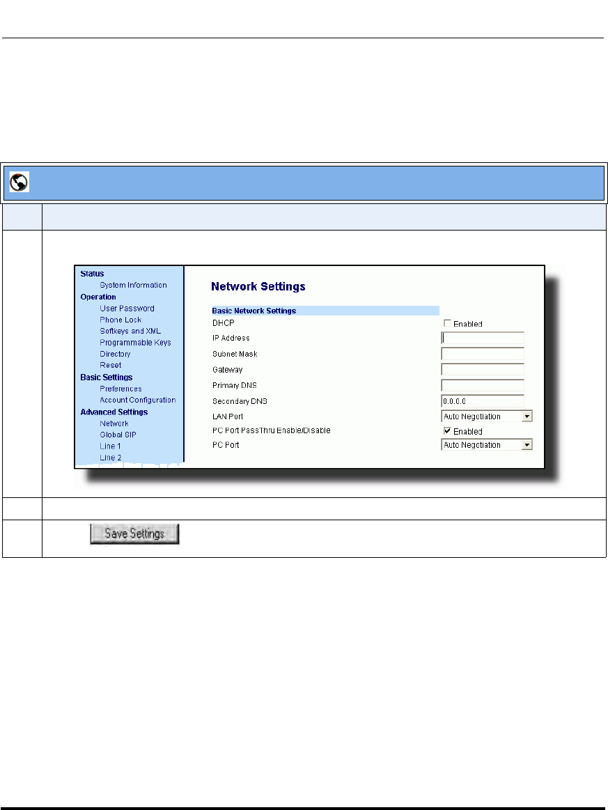
Network Settings
41-001160-03, Rev 00, Releaes 2.4 4-7
Configuring Network and Session Initiation Protocol (SIP) Features
Enabling/Disabling DHCP Using the Aastra Web UI
Use the following procedure to enable/disable DHCP using the Aastra Web
UI.
Aastra Web UI
Step Action
1 Click on Advanced Settings->Network->Basic Network Settings.
2 Enable the "DHCP" field by checking the check box. (Disable this field by unchecking the box).
3 Click to save your settings.
Draft 1
Network Settings
4-8 41-001160-03, Rev 00, Releaes 2.4
IP Phone Administrator Guide
DHCP Options 60, 66, and 43 Server Configurations
Option 66
The IP Phones support download protocols according to RFC2131 and RFC1541
(TFTP, FTP, HTTP,. HTTPS) to support DHCP option 66. Option 66 is part of the
DHCP Offer message that the DHCP server generates to tell the phone which
configuration server it should use to download new firmware and configuration
files.
For DHCP to automatically populate the IP address or domain name for the
servers, your DHCP server must support Option 66. Option 66 is responsible for
forwarding the server’s IP address or domain name to the phone automatically. If
your DHCP server does not support Option 66, you must manually enter the IP
address or domain name for your applicable configuration server into your IP
phone configuration.
Options 60 and 43
The Aastra phones also support Option 60 and Option 43 as per RFC 2132.
Option 60 (Vendor Class Identifier) provides the DHCP server with a unique
identifier for each phone model. This enables a system administrator to send the
phone a customized Server Configuration in option 43.
The table below lists the identifier values for each phone model.
Model Identifier Value
9143i AastraIPPhone9143i
9480i AastraIPPhone9480i
9480i CT AastraIPPhone9480iCT
6751i AastraIPPhone51i
6753i AastraIPPhone53i
6755i AastraIPPhone55i
6757i AastraIPPhone57i
6757i CT AastraIPPhone57iCT
Draft 1

Network Settings
41-001160-03, Rev 00, Releaes 2.4 4-9
Configuring Network and Session Initiation Protocol (SIP) Features
The System administrator can use the Vendor Class Identifier to send the phone a
customized Server Configuration in option 43 (Vendor-Specific information).
Using Option 43 to Customize the IP Phone
A System Administrator can customize the IP Phone(s) in the network by entering
a text string in the phone’s configuration files. The following is an Option 43
example using Linux.
On the startup of the phones, when the DHCP server receives the request with the
information in this example, it allows the 6757i phones to use FTP and the 6757i
CT phones to use TFTP from the same server.
Linux Example
A System Administrator can enter the following in the Aastra IP Phone
configuration file:
option space AastraIPPhone57i;
option AastraIPPhone57i.cfg-server-name code 02 = text;
option space AastraIPPhone57iCT;
option AastraIPPhone57iCT.cfg-server-name code 02 = text;
Subnet 192.168.1.0 netmask 255.255.255.0 {
class "vendor-class-57i" {
match if option vendor-class-identifier="AastraIPPhone57i";
vendor-option-space AastraIPPhone57i;
option AastraIPPhone57i.cfg-server-name "ftp://
username:password@10.10.10.1";
}
class "vendor-class-57iCT" {
match if option vendor-class-identifier="AastraIPPhone57iCT";
vendor-option-space AastraIPPhone57iCT;
option AastraIPPhone57iCT.cfg-server-name "tftp://10.10.10.1";
}
}
Note: If Aastra IP Phones receive the server configuration from both
DHCP Option 66 and DHCP Option 43, then Option 43 takes precedence
over Option 66.
Draft 1

Network Settings
4-10 41-001160-03, Rev 00, Releaes 2.4
IP Phone Administrator Guide
Your DHCP server configuration file, such as the dhcpd.conf file, may include one
of these lines to configure the configuration server protocol and the server details.
Protocol Format Examples
HTTP http://<server>/<path> option tftp-server-name “http://192.168.1.45”;
option tftp-server-name “http://192.168.1.45/path”;
option tftp-server-name “http://httpsvr.example.com/path”;
HTTPS https://<server>/<path> option tftp-server-name “https://192.168.1.45”;
option tftp-server-name “https://192.168.1.45/path”;
option tftp-server-name “https://httpssvr.example.com/
path”;
FTP ftp://user:password@ftpserver option tftp-server-name “ftp://192.168.1.45”;
option tftp-server-name “ftp://ftpsvr.example.com”;
(for anonymous user)
option tftp-server-name “ftp://userID:password@
ftpsvr.example.com”;
TFTP tftp://tftpserver option tftp-server-name “192.168.1.45”;
option tftp-server-name “tftpsvr.example.com”;
option tftp-server-name “tftp://tftpsvr.example.com”;
Draft 1
Network Settings
41-001160-03, Rev 00, Releaes 2.4 4-11
Configuring Network and Session Initiation Protocol (SIP) Features
Using Option 12 Hostname on the IP Phone
If you set the phone to use DHCP Option 12, the phone automatically sends this
option to the configuration server. This option specifies the hostname (name of the
client). The name may or may not be qualified with the local domain name (based
on RFC 2132). See RFC 1035 for character set restrictions.
An Administrator can change the “Hostname” for the DHCP Option 12 via the
configuration files, the IP Phone UI, and the Aastra Web UI.
Configuring DHCP Option 12 Hostname on the IP Phone
Use the following procedures to configure DHCP Option 12 Hostname on the IP
Phone.
Notes:
1. The hostname of [<model><MAC address>] automatically
populates the field on initial startup of the phone. For example, for a
6753i, the “Hostname” field is automatically populated as
“53i00085D164435”, where the model number is “6753i” and the MAC
address is “00085D164435”.
2. If the configuration server sends the hostname back to the phone in
a DHCP Reply Packet, the hostname is ignored.
Configuration Files
For specific parameters you can set in the configuration files, see Appendix A, the section, “DHCP Option
Settings” on page A-13.
Draft 1
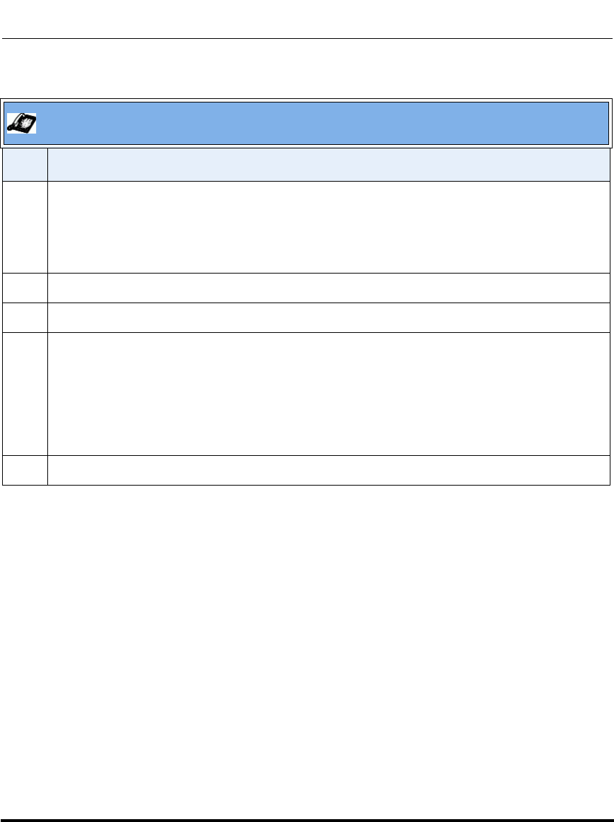
Network Settings
4-12 41-001160-03, Rev 00, Releaes 2.4
IP Phone Administrator Guide
Aastra IP Phone UI
Step Action
1 Press Options, and then select Administrator Menu.
On the 6751i:
Press Services, and then select Options->Administrator Menu.
2Select Network Settings.
3Select Hostname.
4 By default, the “Hostname” field is automatically populated with [<Model><MAC address>] of your
phone (for example, 53i00085D164435).
If you want to change the hostname, enter a hostname for your phone in the “Hostname” field, then
press DONE.
Valid values are up to 64 alpha-numeric characters. You can use a fully qualified domain name if
required.
5 Restart the phone for the change to take affect.
Draft 1
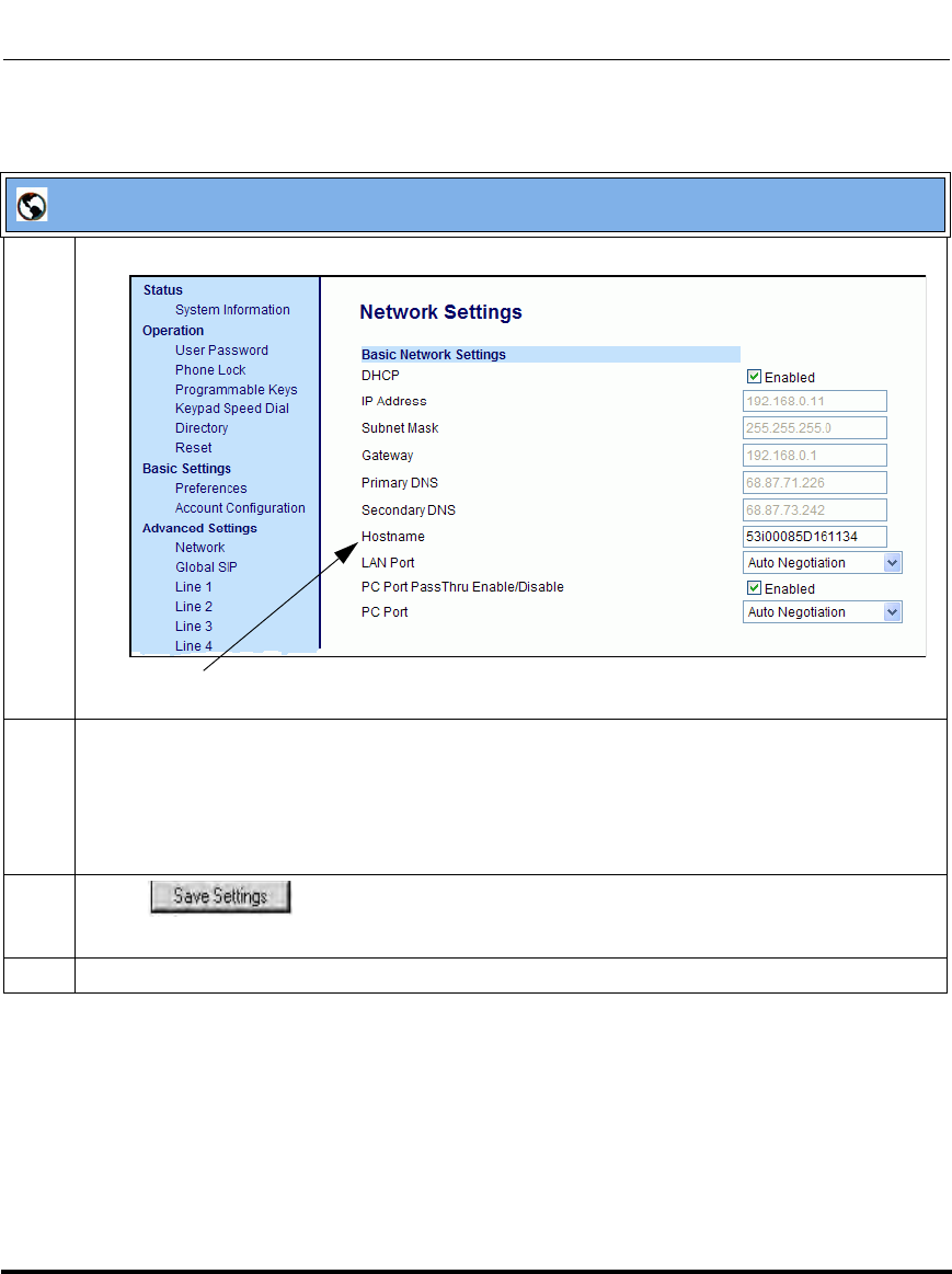
Network Settings
41-001160-03, Rev 00, Releaes 2.4 4-13
Configuring Network and Session Initiation Protocol (SIP) Features
Aastra Web UI
1 Click on Advanced Settings->Network->Basic Network Settings.
2 By default, the “Hostname” field is automatically populated with [<Model><MAC address>] of your
phone (for example, 53i00085D164435).
If you want to change the hostname, enter a hostname for your phone in the “Hostname” field.
Valid values are up to 64 alpha-numeric characters. You can use a fully qualified domain name if
required.
3 Click to save your changes.
Note: Changing the “Hostname” field requires a reboot of your phone.
4 Click on Operation->Reset, and click RESTART.
Hostname
Draft 1
Network Settings
4-14 41-001160-03, Rev 00, Releaes 2.4
IP Phone Administrator Guide
Using Option 77 User Class on the IP Phone
DHCP Option 77 User Class is sent in DHCP request packets from the phone to
the configuration server. This Option 77 defines specific User Class identifiers to
convey information about a phone’s software configuration or about its user's
preferences. For example, you can use the User Class option to configure all
phones in the Accounting Department with different user preferences than the
phones in the Marketing Department. A DHCP server uses the User Class option
to choose the address pool for which it allocates an address from, and/or to select
any other configuration option.
An Administrator can configure the DHCP Option 77 User Class via the
configuration files, the IP Phone UI, and the Aastra Web UI.
Configuring DHCP Option 77 User Class on the IP Phone
Use the following procedures to configure DHCP Option 77 User Class on the IP
Phone.
Notes:
1. If the User Class is not specified (left blank) in the DHCP request
packet, the phone does not send the User Class DHCP Option 77.
2. Multiple User Classes inside a DHCP Option 77 are not supported.
3. DHCP Option 77 may affect the precedence of DHCP Options,
dependent on the DHCP Server.
Configuration Files
For specific parameters you can set in the configuration files, see Appendix A, the section, “DHCP Option
Settings” on page A-13.
Draft 1
Network Settings
41-001160-03, Rev 00, Releaes 2.4 4-15
Configuring Network and Session Initiation Protocol (SIP) Features
Aastra IP Phone UI
Step Action
1 Press Options, and then select Administrator Menu.
On the 6751i:
Press Services, and then select Options->Administrator Menu.
2Select Network Settings.
3Select DHCP Settings.
4Select DHCP User Class.
5 In the “DHCP User Class” field, enter a DHCP User Class to apply to your phones, then press
DONE.
Valid values are up to 64 alpha-numeric characters. For example, “admin”.
6 Restart the phone for the change to take affect.
Draft 1
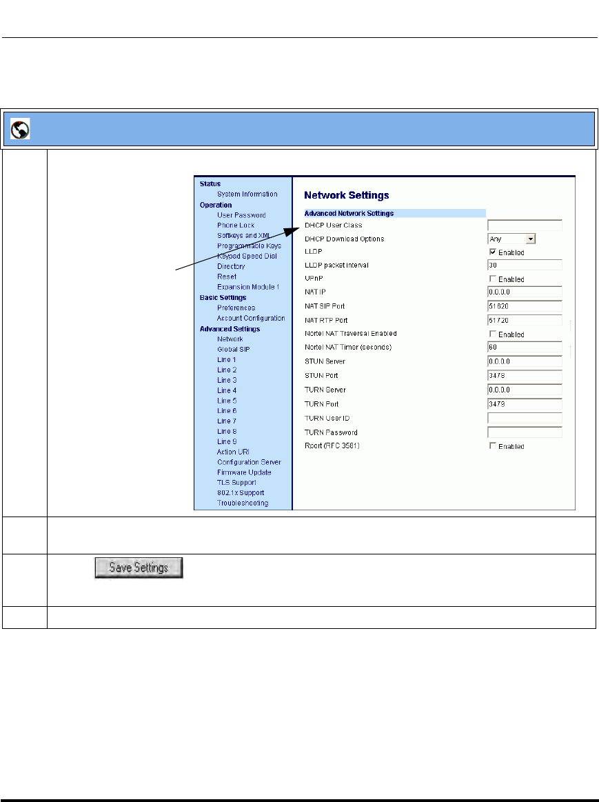
Network Settings
4-16 41-001160-03, Rev 00, Releaes 2.4
IP Phone Administrator Guide
.
Aastra Web UI
1 Click on Advanced Settings->Network->Advanced Network Settings.
2 In the “DHCP User Class” field, enter a DHCP User Class to apply to your phones. For example,
“admin”. Valid values are up to 64 alpha-numeric characters.
3 Click to save your changes.
Note: Entering a value in the “DHCP User Class” field requires a reboot of your phone.
4 Click on Operation->Reset, and click RESTART.
DHCP User Class
Draft 1
Network Settings
41-001160-03, Rev 00, Releaes 2.4 4-17
Configuring Network and Session Initiation Protocol (SIP) Features
Using Options 159 and 160 on the IP Phone
In addition to DHCP options 43 and 66 already supported on the IP Phones, the
phones also support DHCP Options 159 and 160. The IP Phones use the following
order of precedence when deriving the configuration server parameters: 43, 160,
159, 66.
In addition, an administrator can override this order of precedence by setting a
configuration parameter called, dhcp config option override (configuration
files), DHCP Download Options (Aastra Web UI), or Download Options (IP
Phone UI). Setting this parameter results in the phone only using the chosen
DHCP option and ignoring the other options.
For more information about setting DHCP download preference, see
“Configuration Server Download Precedence” on page 4-20..
Configuring DHCP Download Options on the IP Phones
Use the following procedures to configure DHCP Option Override on the IP
Phone.
Warning: Administrators should review the updated IP phone DHCP
option precedence order and configuration options to avoid potential
impact to existing Aastra IP phone deployments.
Configuration Files
For specific parameters you can set in the configuration files, see Appendix A, the section, “DHCP Option
Settings” on page A-13.
Draft 1
Network Settings
4-18 41-001160-03, Rev 00, Releaes 2.4
IP Phone Administrator Guide
Aastra IP Phone UI
Step Action
1 Press Options, and then select Administrator Menu.
On the 6751i:
Press Services, and then select Options->Administrator Menu.
2 Enter you Administrator password and press Enter.
3Select Network Settings.
4Select DHCP Settings.
5Select Download Options. The following list displays:
•Any (default) - no override - uses normal precedence order of 43, 160, 159, 66.
•Option 43
•Option 66
• Option 159
• Option 160
• Disabled (Ignores all DHCP configuration options (43, 66, 159, 160))
6 Choose an option that you want to use to override the DHCP normal precedence order, and press
DONE.
7 Restart the phone for the selection to take affect.
Draft 1
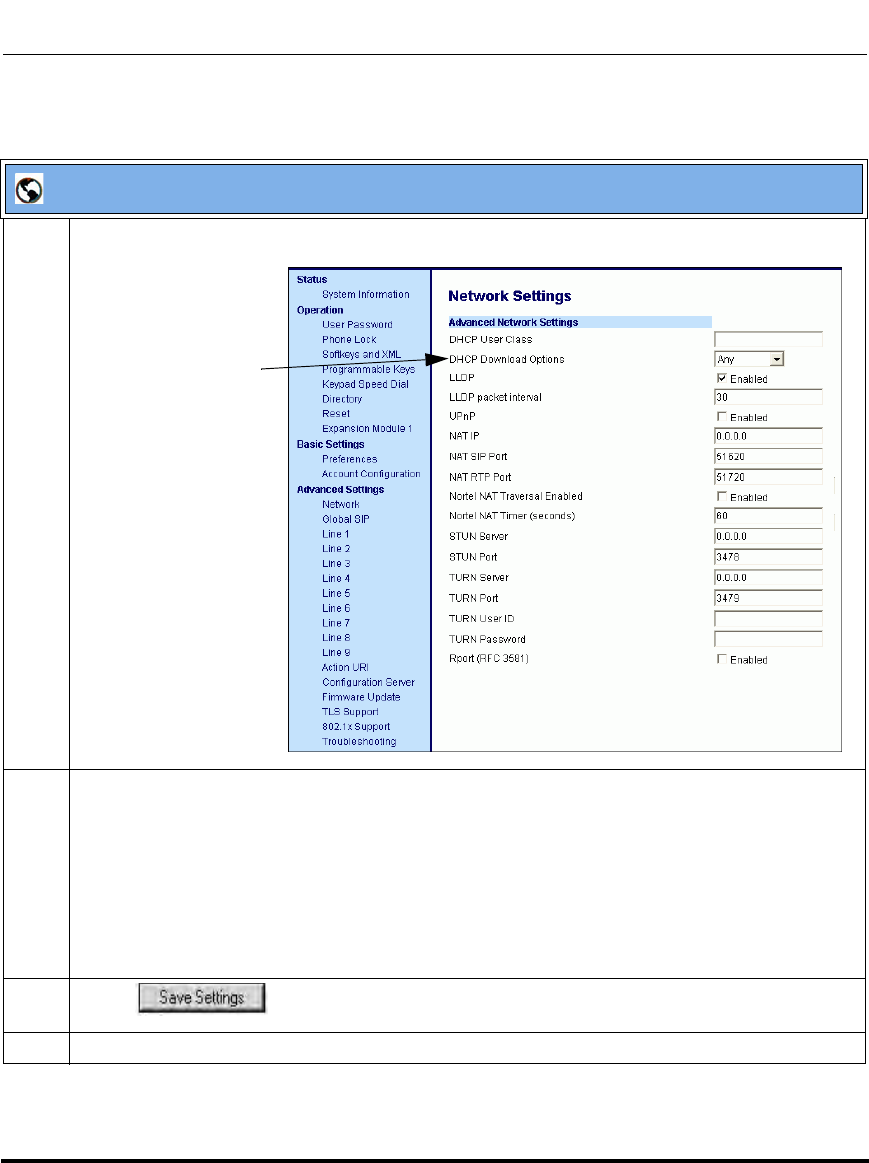
Network Settings
41-001160-03, Rev 00, Releaes 2.4 4-19
Configuring Network and Session Initiation Protocol (SIP) Features
Aastra Web UI
1 Click on Advanced Settings->Network->Advanced Network Settings.
2In the “DHCP Download Options” field, select an option to use to override the normal precedence
order. Valid values are:
•Any (default) - no override - uses normal precedence order of 43, 160, 159, 66.
•Option 43
•Option 66
•Option 159
•Option 160
• Disabled (Ignores all DHCP configuration options (43, 66, 159, 160))
3 Click to save your changes.
4 Click on Operation->Reset, and restart the phone for the changes to take affect.
DHCP Download
Options Parameter
Draft 1

Network Settings
4-20 41-001160-03, Rev 00, Releaes 2.4
IP Phone Administrator Guide
Configuration Server Download Precedence
An Administrator can set the phone’s download precedence to ignore DHCP,
(only during the boot when the remote configuration server is contacted) and
use the following precedence instead:
1. Configuration URI,
2. DHCP, and then
3. Direct configuration.
To configure the download precedence, you use the option value (-1) as the value
for the “dhcp config option override” parameter in the configuration files.
Setting this parameter to “-1” causes all DHCP configuration options to be
ignored.
Configuring a Download Precedence Using the Configuration Files
Use the following procedure to configure the DHCP download precedence using
the configuration files.
Configuration Files
For specific parameters you can set in the configuration files, see Appendix A, the section, “DHCP Option
Settings” on page A-13.
Draft 1
Network Settings
41-001160-03, Rev 00, Releaes 2.4 4-21
Configuring Network and Session Initiation Protocol (SIP) Features
Configuring a Download Precedence Using the IP Phone UI
Use the following procedure to configure a download precedence using the IP
Phone UI.
Aastra IP Phone UI
Step Action
1 Press Options, and then select Administrator Menu.
On the 6751i:
Press Services, and then select Options->Administrator Menu.
2 Enter you Administrator password and press Enter.
3Select Network Settings.
4Select DHCP Settings.
5Select Download Options.
• Disabled (Ignores all DHCP configuration options (43, 66, 159, 160))
6 Select the Disabled option and press Enter.
Note: The “Disabled” download option performs the same function as the “-1” in the configuration
files (ignores DHCP options).
7 Restart the phone for the selection to take affect.
Draft 1
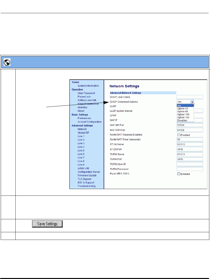
Network Settings
4-22 41-001160-03, Rev 00, Releaes 2.4
IP Phone Administrator Guide
Configuring a Download Precedence Using the Aastra Web UI
Use the following procedure to configure a download precedence using the Aastra
Web UI.
Aastra Web UI
1 Click on Advanced Settings->Network->Advanced Network Settings.
2 In the “DHCP Download Options” field, select “Disabled” from the list of options.
Note: In the Aastra Web UI, the “Disabled” download option performs the same function as the “-1”
in the configuration files (ignores DHCP options).
3 Click to save your setting.
4 Select Operation->Reset, and click Restart to reboot the phone.
DHCP Download Options
Parameter
Draft 1
Network Settings
41-001160-03, Rev 00, Releaes 2.4 4-23
Configuring Network and Session Initiation Protocol (SIP) Features
Multiple DHCP Servers
The IP Phones can receive messages from multiple DHCP servers.
After the phone receives its first DHCP message, it listens for a specific time
period, for more DHCP messages. If the first DHCP offer contains configuration
server information (Options 43, 66, 159 or 160), then the phone times out and
continues using the first DHCP offer, without listening for more DHCP offers. If
the first DHCP message contains no configuration server information, the phone
continues to listen for other DHCP messages. If the second DHCP message
contains configuration server information and other conditions, the phone chooses
the second DHCP message over the initial DHCP message.
IMPORTANT NOTE
Users currently using multiple DHCP servers on a single network could be
affected by this feature.
DNS Caching
The IP phones have the ability to cache DNS requests according to RFC1035 and
RFC2181. The phone caches DNS lookups according to the TTL field, so that the
phone only performs another lookup for an address when the TTL expires.
Note: If the DHCP Download Options parameter is enabled with a
value (Option 43, Option 66, Option 159, or Option 160), the phone
checks the override option setting before timing out.
Draft 1
Network Settings
4-24 41-001160-03, Rev 00, Releaes 2.4
IP Phone Administrator Guide
Configuring Network Settings Manually
If you disable DHCP on your phone, you need to configure the following network
settings manually:
• IP Address
• Subnet Mask
• Gateway
• Primary DNS
• Secondary DNS
You can configure the network settings using the configuration files, the IP phone
UI, or the Aastra Web UI.
Note: If you disable DHCP on the phone, the phone uses the TFTP
protocol as the default server protocol. If you want to specify a different
protocol to use, see “Configuration Server Protocol” on page 4-108.
Configuration Files
For specific parameters you can set in the configuration files, see Appendix A, the section, “Network
Settings” on page A-8.
IP Phone UI
Step Action
1 Press on the phone to enter the Options List.
2Select Administrator Menu.
3 Enter your Administrator password.
Note: The IP Phones accept numeric passwords only.
4Select Network Settings.
5Select IP Address and enter the IP address of the phone.
6Select Subnet Mask and enter the subnet mask.
Draft 1
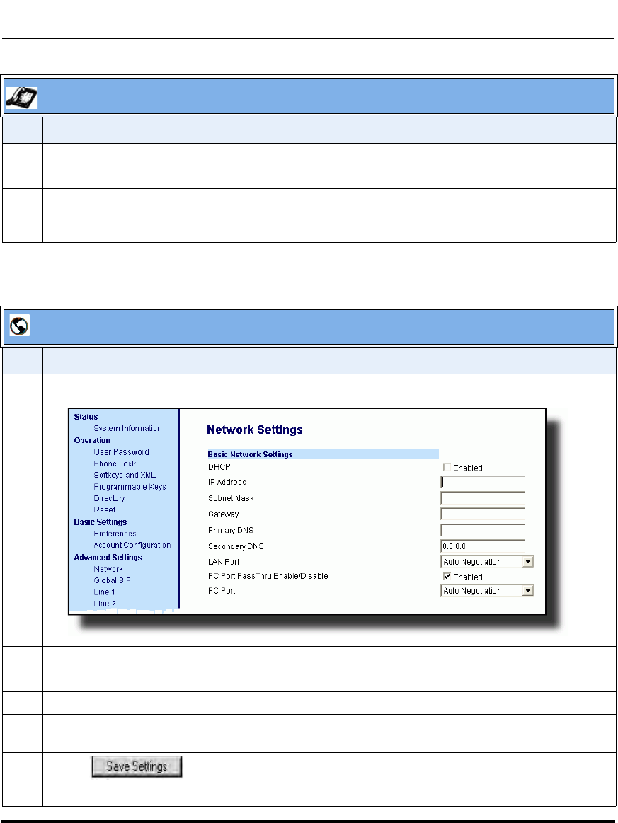
Network Settings
41-001160-03, Rev 00, Releaes 2.4 4-25
Configuring Network and Session Initiation Protocol (SIP) Features
.
7Select Gateway and enter the gateway address.
8Select DNS and enter a Primary and/or Secondary DNS server.
9 Press Done to save the changes.
The IP phone is manually configured.
Aastra Web UI
Step Action
1 Click on Advanced Settings->Network->Basic Network Settings.
2 Enter an IP address of the phone in the IP Address field.
3 Enter a subnet mask in the Subnet Mask field.
4 Enter a gateway address in the Gateway field.
5 Enter a Primary DNS in the Primary DNS field, and/or a secondary DNS in the Secondary DNS
field.
6 Click to save your settings.
The IP phone is manually configured.
IP Phone UI
Step Action
Draft 1

Network Settings
4-26 41-001160-03, Rev 00, Releaes 2.4
IP Phone Administrator Guide
Configuring LAN and PC Port Negotiation
Ethernet is the computer networking technology for local area networks (LANs).
You use the LAN Port to connect to a LAN using a twisted pair 10BASE-T cable
to transmit 10BASE-T Ethernet. You use the PC Port to connect to the
configuration server (your PC).
There are two Ethernet ports on the rear of the IP phones: LAN Port and PC Port.
Using the Aastra Web UI, you can select the type of transmission you want these
ports to use to communicate over the LAN. The IP phones support each of the
following methods of transmission:
• Auto-negotiation
• Half-duplex (10Mbps or 100 Mbps)
• Full-duplex (10Mbps or 100Mbps)
Auto-negotiation
Auto-negotiation is when two connected devices choose common transmission
parameters. In the auto-negotiation process, the connected devices share their
speed and duplex capabilities and connect at the highest common denominator
(HCD). Auto-negotiation can be used by devices that are capable of different
transmission rates (such as 10Mbit/sec and 100Mbit/sec), different duplex modes
(half duplex and full duplex) and/or different standards at the same speed. You can
set the LAN and PC Ports on the IP phones to auto-negotiate during transmission.
Half-Duplex (10Mbps or 100Mbps)
Half-duplex data transmission means that data can be transmitted in both
directions on a signal carrier, but not at the same time. For example, on a LAN
using a technology that has half-duplex transmission, one device can send data on
the line and then immediately receive data on the line from the same direction in
which data was just transmitted. Half-duplex transmission implies a bidirectional
line (one that can carry data in both directions). On the IP phones, you can set the
half-duplex transmission to transmit in 10Mbps or in 100Mbps.
Draft 1
Network Settings
41-001160-03, Rev 00, Releaes 2.4 4-27
Configuring Network and Session Initiation Protocol (SIP) Features
Full-Duplex (10Mbps or 100Mbps)
Full-duplex data transmission means that data can be transmitted in both
directions on a signal carrier at the same time. For example, on a LAN with a
technology that has full-duplex transmission, one device can be sending data on
the line while another device is receiving data. Full-duplex transmission implies a
bidirectional line (one that can move data in both directions). On the IP phones,
you can set the full-duplex transmission to transmit in 10Mbps or in 100Mbps.
Configuring the LAN Port and PC Port
You can configure the Ethernet port transmission method to use on the IP phones
using the configuration files, the IP Phone UI, or the Aastra Web UI.
Configuration Files
For specific parameters you can set in the configuration files, see Appendix A, the section, “Network
Settings” on page A-8.
IP Phone UI
Step Action
1 Press on the phone to enter the Options List.
2Select Administrator Menu.
3 Enter your Administrator password.
Note: The IP Phones accept numeric passwords only.
4Select Network Settings.
5Select Ethernet.
6Select LAN Port Link.
Draft 1

Network Settings
4-28 41-001160-03, Rev 00, Releaes 2.4
IP Phone Administrator Guide
7 Select a negotiation method to use on port 0 and press Done. Valid values are:
• AutoNegotiation
• FullDuplex 10Mbps
• FullDuplex 100Mbps
• HalfDuplex 10Mbps
• HalfDuplex 100Mbps
Default is AutoNegotiation.
8Select PC Port Link.
9 Select a negotiation method to use on port 1and press Done. Valid values are:
• AutoNegotiation
• FullDuplex 10Mbps
• FullDuplex 100Mbps
• HalfDuplex 10Mbps
• HalfDuplex 100Mbps
Default is AutoNegotiation.
10 Press Done (3 times) to finish configuring the configuration server protocol for the IP phone.
Note: The session prompts you to restart the IP phone to apply the configuration settings.
11 Select Restart.
IP Phone UI
Step Action
Draft 1
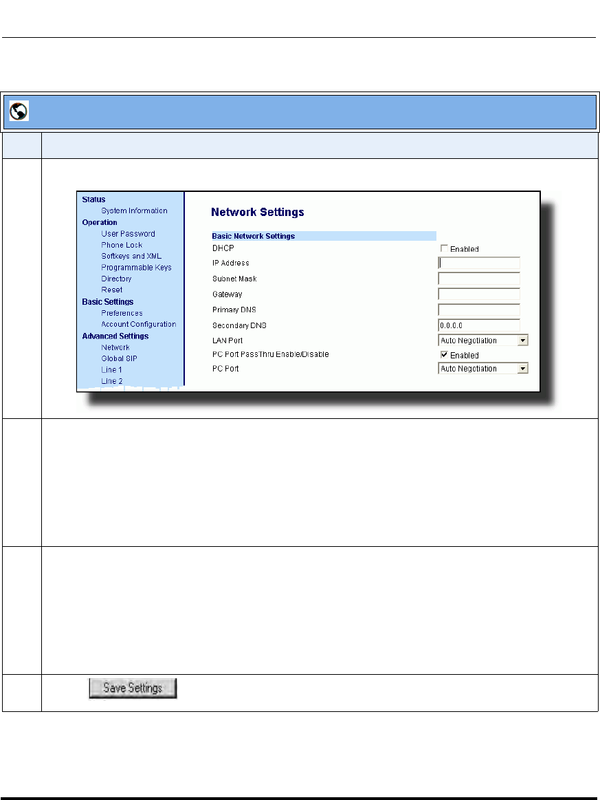
Network Settings
41-001160-03, Rev 00, Releaes 2.4 4-29
Configuring Network and Session Initiation Protocol (SIP) Features
Aastra Web UI
Step Action
1 Click on Advanced Settings->Network->Basic Network Settings.
2 In the “LAN Port” field, select a negotiation method to use on port 0. Valid values are:
• Auto Negotiation
• Full Duplex, 10Mbps
• Full Duplex, 100Mbps
• Half Duplex, 10Mbps
• Half Duplex, 100Mbps
Default is Auto Negotiation.
3 In the “PC Port” field, select a negotiation method to use on port 1. Valid values are:
• Auto Negotiation
• Full Duplex, 10Mbps
• Full Duplex, 100Mbps
• Half Duplex, 10Mbps
• Half Duplex, 100Mbps
Default is Auto Negotiation.
4 Click to save your settings.
Draft 1
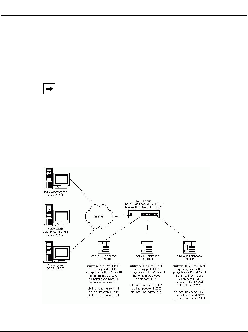
Network Settings
4-30 41-001160-03, Rev 00, Releaes 2.4
IP Phone Administrator Guide
Advanced Network Settings
You can set advanced network settings on the IP phone such as, Network Address
Translation (NAT), Nortel NAT, Network Time Protocol (NTP) Time Servers,
Virtual LAN (VLAN), and Quality of Service (QoS), and Universal Plug and Play
(UPnP) using the Aastra Web UI or the configuration files.
Network Address Translation (NAT)
The protocols used by all IP phones do not interoperate completely with Network
Address Translation (NAT). For the IP Phones, specific configuration parameters
allow the phone to operate while connected to a network device that enforces
NAT. The following is a sample network using a NAT proxy and relevant IP
phone configuration parameters.
Note: The available advanced network parameters via the IP phone UI
are NAT, Nortel NAT, UPnP, VLAN, and QoS only.
Draft 1

Network Settings
41-001160-03, Rev 00, Releaes 2.4 4-31
Configuring Network and Session Initiation Protocol (SIP) Features
Nortel Proxy/Registrar
The phone at IP address 10.10.10.10 is configured to register with the proxy at
63.251.195.10. Because it is a Nortel proxy, the configuration must additionally
include the "sip nortel nat support" and "sip nortel nat timer" settings, telling the
firmware to enhance the protocols with Nortel specific content.
SBC or ALG proxy/registrar
The phone at IP address 10.10.10.20 is configured to register with the proxy at
63.251.195.20. Because the proxy/registrar has session border control (SBC) or
application layer gateway (ALG) functionality, no additional IP phone
configuration is required.
Other proxy/registrars
The phone at IP address 10.10.10.30 is configured to register with the proxy at
63.251.195.30. Because this proxy/registrar is not a Nortel proxy and has no SBC
or ALG functionality, the configuration must additionally include the "sip nat ip"
and "sip nat port" settings that contain the public ip address of the NAT router and
the port used for call signaling messages. This information is embedded in
protocol messages to allow the proxy/registrar to reach the IP phone on the NAT
router private network.
NAT router configuration
You must configure the NAT router to allow signaling or media packets
containing the various UDP port values to flow between the private and public
networks that are separated by the NAT router. In the sample network, the NAT
router must not filter packets using ports 3000, 5060, 6060, 16420, and 16430.
Note: This IP phone uses RTP port 3000 (the default value) since an RTP
port was not explicitly configured.
Draft 1
Network Settings
4-32 41-001160-03, Rev 00, Releaes 2.4
IP Phone Administrator Guide
Nortel Networks NAT
Nortel Networks provides a proprietary solution to support connectivity to their
proxies from phones placed behind devices (such as routers or firewalls) that use
NAT. Nortel uses the SIP ping request/reply between the Nortel proxy and the
phone in order to keep the connection through the router or firewall active. A SIP
Nortel NAT timer is the interval, in seconds (default is 60), that the phone sends
SIP ping requests to the Nortel proxy.
When you use NAT in your network, a network device (usually a router) provides
a “firewall” division between the public network (usually the Internet) and the
private network, to which the IP Phones are connected. The firewall protects the
network by translating port numbers within packets between the public and
private networks. When using NAT, and an RTP packet arrives at the public side
of the firewall, it is expected to have the NAT RTP port within the packet. If the
packet contains the proper port number, the firewall changes the NAT RTP port
number in the packet to the RTP port number that the phone recognizes, and then
forwards it onto the private network. Often the router/firewall automatically
discovers these various port numbers and other information concerning public and
private sides of the network with the use of the Universal Plug and Play (UPnP)
Protocol between the phone and the router/firewall.
Configuring Nortel NAT (optional)
You can configure Nortel NAT using the configuration files, the IP phone UI, or
the Aastra Web UI.
Configuration Files
For specific parameters you can set in the configuration files, see Appendix A, the section, “Network
Address Translation (NAT) Settings” on page A-29.
Draft 1
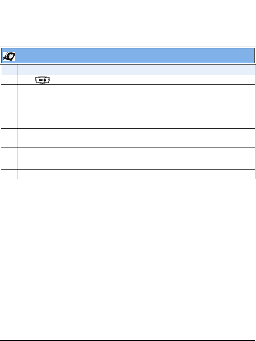
Network Settings
41-001160-03, Rev 00, Releaes 2.4 4-33
Configuring Network and Session Initiation Protocol (SIP) Features
IP Phone UI
Step Action
1 Press on the phone to enter the Options List.
2Select Administrator Menu.
3 Enter your Administrator password.
Note: The IP Phones accept numeric passwords only.
4Select Network Settings.
5Select NAT Settings.
6Select Nortel NAT.
7 Press Change to set either “Enabled” or “Disabled”.
8 Press Done (3 times) to finish.
Note: The session prompts you to restart the IP phone to apply the configuration settings.
9Select Restart.
Draft 1
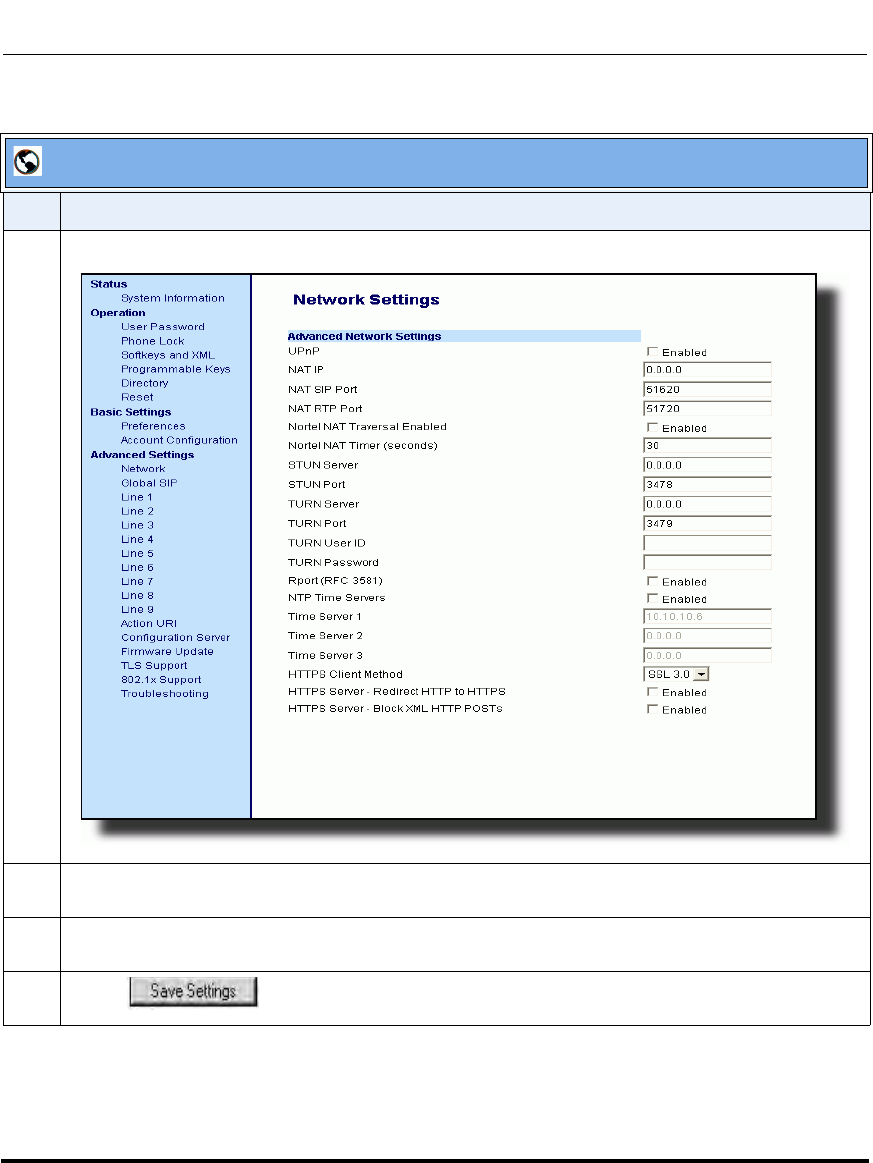
Network Settings
4-34 41-001160-03, Rev 00, Releaes 2.4
IP Phone Administrator Guide
.
Aastra Web UI
Step Action
1 Click on Advanced Settings->Network->Advanced Network Settings.
2 Select Yes (enable) or No (disable) in the "Nortel NAT Traversal Enabled" field to enable or disable
NAT for a Nortel network.
3 Enter a time, in seconds, in the "Nortel NAT timer" field. Valid values are 0 to 2147483647.
Default is 60.
4 Click to save your settings.
Draft 1
Network Settings
41-001160-03, Rev 00, Releaes 2.4 4-35
Configuring Network and Session Initiation Protocol (SIP) Features
Configuring NAT Address and Port (optional)
You can also configure a specific NAT address and port on the IP phone using the
configuration files, IP Phone UI, or Aastra Web UI.
Configuration Files
For specific parameters you can set in the configuration files, see Appendix A, the section, “Network
Address Translation (NAT) Settings” on page A-29.
IP Phone UI
Step Action
1 Press on the phone to enter the Options List.
2Select Administrator Menu.
3 Enter your Administrator password.
Note: The IP Phones accept numeric passwords only.
4Select Network Settings.
5Select Static NAT.
6Select NAT IP.
7 Enter a public IP address of your NAT device in dotted-decimal format.
8 Press Done to save the setting.
9Select NAT SIP Port. Default is 51620.
10 Enter the public SIP signalling port number of your NAT device.
11 Press Done to save the setting.
12 Select NAT RTP Port.
13 Enter the RTP Port number of your NAT device. Default is 51720.
14 Press Done (4 times) to finish.
Note: The session prompts you to restart the IP phone to apply the configuration settings.
15 Select Restart.
Draft 1
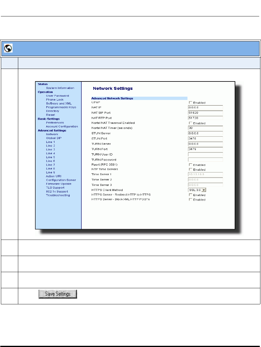
Network Settings
4-36 41-001160-03, Rev 00, Releaes 2.4
IP Phone Administrator Guide
.
Aastra Web UI
Step Action
1 Click on Advanced Settings->Network->Advanced Network Settings.
2 Enter a NAT IP address in the "NAT IP" field. The value must be entered in dotted decimal format.
For example, 0.0.0.0. The “NAT IP” is the public IP address of your NAT device.
3 Enter a NAT port in the "NAT SIP Port" field. Default is 51620.
The “NAT SIP Port” is the public SIP signalling port number of your NAT device.
4 Enter a NAT port in the "NAT RTP Port" field. Default is 51720.
The “NAT RTP Port” is the RTP Port number of your NAT device.
5 Click to save your settings.
Draft 1

Network Settings
41-001160-03, Rev 00, Releaes 2.4 4-37
Configuring Network and Session Initiation Protocol (SIP) Features
SIP and TLS Source Ports for NAT Traversal
A System Administrator can configure the SIP and TLS source ports on the IP
Phone. Previously, the IP phone used default values (5060 for UDP/TCP and 5061
for TLS). The two new parameters for configuring the SIP and TLS source ports
are:
• sip local port
• sip local tls port
You can configure the SIP and TLS source ports using the configuration files or
the Aastra Web UI. After configuring these parameters, you must reboot the
phone.
If NAT is disabled, the port number also shows in the VIA and Contact SIP
headers.
If you enable NAT, the phone uses the NAT port number (and NAT IP address) in
the Via and Contact SIP headers of SIP messages, but still use the configured
source port.
Note: By default, the IP phones use symmetric UDP signaling for
outgoing UDP SIP messages. When symmetric UDP is enabled, the IP
phone generates and listens for UDP messages using port 5060.If
symmetric UDP signaling is disabled, the phone sends from random
ports but it listens on the configured SIP local port.
Draft 1
Network Settings
4-38 41-001160-03, Rev 00, Releaes 2.4
IP Phone Administrator Guide
Configuring SIP and TLS Source Ports Using the Configuration Files
You use the following parameters to configure SIP and TLS ports for NAT
traversal:
• sip local port
• sip local tls port
Configuration Files
For specific parameters you can set in the configuration files, see Appendix A, the sections:
•“Local SIP UDP/TCP Port Setting” on page A-32.
•“Local SIP TLS Port” on page A-32.
Draft 1
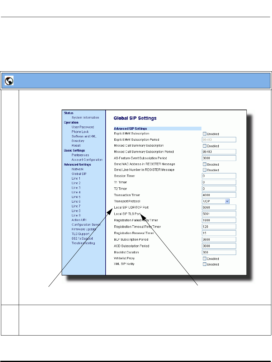
Network Settings
41-001160-03, Rev 00, Releaes 2.4 4-39
Configuring Network and Session Initiation Protocol (SIP) Features
Configuring SIP and TLS Source Ports Using the Aastra Web UI
Use the following procedure to configure SIP and TLS source ports using the
Aastra Web UI.
Aastra Web UI
1 Click on Advanced Settings->Global SIP->Advanced SIP Settings.
.
2The “Local SIP UDP/TCP Port” field has a default value of 5060. Change this value if required to a
value greater than 1024 and less than 65535.
Note: It is recommended that you avoid the conflict RTP port range in case of a UDP transport.
“Local SIP UDP/TCP Port” Parameter “Local SIP TLS Port” Parameter
Draft 1
Network Settings
4-40 41-001160-03, Rev 00, Releaes 2.4
IP Phone Administrator Guide
HTTPS Client/Server Configuration
HTTPS is a Web protocol that encrypts and decrypts user page requests as well as
the pages that are returned by the Web server. HTTPS uses Secure Socket Layer
(SSL) or Transport Layer Security (TLS) as a sublayer under its regular HTTP
application layering. SSL is a commonly-used protocol for managing the
security of a message transmission on the Internet. It uses a 40-bit key size
for the RC4 stream encryption algorithm, which is considered an adequate degree
of encryption for commercial exchange. TLS is a protocol that ensures privacy
between communicating applications and their users on the Internet. When a
server and client communicate, TLS ensures that no third party may eavesdrop or
tamper with any message. TLS is the successor to SSL.
When an HTTPS client opens and closes its TCP socket, the SSL software
respectively handshakes upon opening and disconnects upon closing from the
HTTPS server. The main HTTPS client functions are:
• Downloading of configuration files and firmware images.
• Downloading of script files based on an “HTTPS://” URL supplied by a
softkey definition.
3The “Local SIP TLS Port” field has a default value of 5061. Change this value if required to a value
greater than 1024 and less than 65535.
Note: It is recommended that you avoid the conflict with any TCP ports being used. For example:
WebUI HTTP server on 80/tcp and HTTPS on 443/tcp.
4 Click to save your changes.
Note: HTTPS uses port 443 instead of HTTP port 80 in its interactions
with the TCP/IP lower layer.
Aastra Web UI
Draft 1
Network Settings
41-001160-03, Rev 00, Releaes 2.4 4-41
Configuring Network and Session Initiation Protocol (SIP) Features
The HTTPS server provides HTTP functionality over secure connections. It
coexists with the HTTP server but has its own set of tasks. The main HTTPS
server functions are:
• Delivery of web page content to a browser client over a secure connection.
• Execution of HTTP GET and POST requests received over a secure
connection.
Using the configuration files, the IP phone UI, or the Aastra Web UI, you can
configure the following regarding HTTPS:
• Specify HTTPS security client method to use (TSLv1 or SSLv3)
• Enable or disable HTTP to HTTPS server redirect function
• HTTPS server blocking of XML HTTP POSTS to the phone
Configuring HTTPS Client and Server Settings
Use the following procedures to configure the HTTPS client and server for
the IP phones.
Note: To enable or disable the IP phones to use the HTTPS protocol as
the configuration server, see the section, “Configuring the Configuration
Server Protocol” on page 4-108.
Configuration Files
For specific parameters you can set in the configuration files, see Appendix A, the section, “HTTPS Client
and Server Settings” on page A-33.
Draft 1

Network Settings
4-42 41-001160-03, Rev 00, Releaes 2.4
IP Phone Administrator Guide
IP Phone UI
Step Action
1 Press on the phone to enter the Options List.
2Select Administrator Menu.
3 Enter your Administrator password.
Note: The IP Phones accept numeric passwords only.
4Select Configuration Server.
5Select HTTPS Settings.
Configure HTTPS Client
6Select HTTPS Client.
7Select Client Method.
8 Press Change to select a client method to use for HTTPS. Valid values are:
• SSL 3.0 (default)
•TLS 1.0
9 Press Done to save the changes.
Configure HTTPS Server
10 Select HTTPS Server.
11 Select HTTP->HTTPS.
12 Press Change to select “Yes” or “No”. Default is “No”.
Enabling this feature redirects the HTTP protocol to HTTPS.
13 Press Done to save the changes.
14 Select XML HTTP POSTs.
15 Press Change to select “Yes” or “No”. Default is “No”.
Enabling this feature blocks XML HTTP POSTs from the IP Phone.
16 Press Done (4 times) to finish.
Note: The session prompts you to restart the IP phone to apply the configuration settings.
17 Select Restart.
Draft 1
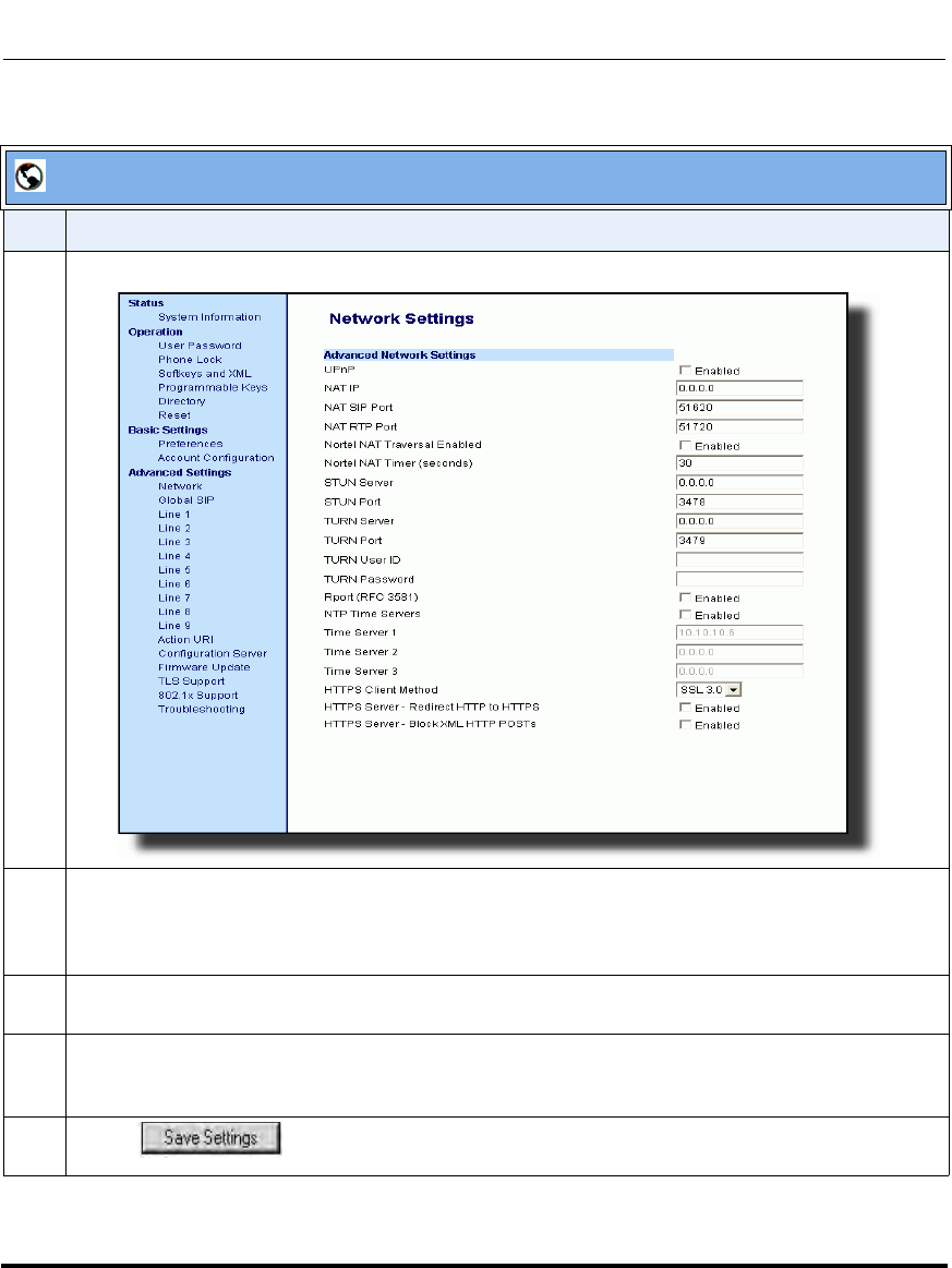
Network Settings
41-001160-03, Rev 00, Releaes 2.4 4-43
Configuring Network and Session Initiation Protocol (SIP) Features
.
Aastra Web UI
Step Action
1 Click on Advanced Settings->Network->Advanced Network Settings.
2 Select an HTTPS client method to use from the HTTPS Client Method field. Valid values are:
SSL 3.0 (default)
TSL 1.0
3 Enable HTTP to HTTPS redirect by checking the HTTPS Server - Redirect HTTP to HTTPS field
check box. (Disable this field by unchecking the check box). Default is disabled.
4 Enable the blocking of XML HTTP POSTs by the HTTPS server by checking the HTTPS Server -
Block XML HTTP POSTs field check box. (Disable this field by unchecking the check box). Default is
disabled.
5 Click to save your settings.
Draft 1

Network Settings
4-44 41-001160-03, Rev 00, Releaes 2.4
IP Phone Administrator Guide
HTTPS Server Certificate Validation
The HTTPS client on the IP Phones support validation of HTTPS certificates.
This feature supports the following:
• Verisign, GeoTrust, and Thawte signed certificates
• User-provided certificates
• Checking of hostnames
• Checking of certificate expiration
• Ability to disable any or all of the validation steps
• Phone displays a message when a certificate is rejected (except on check-sync
operations)
All validation options are enabled by default.
Certificate Management
Aastra Provided Certificates
The phones come with root certificates from Verisign, GeoTrust, and Thawte
pre-loaded.
User Provided Certificates
The administrator has the option to upload their own certificates onto the phone.
The phone downloads these certificates in a file of .PEM format during boot time
after configuration downloads. The user-provided certificates are saved on the
phone between firmware upgrades but are deleted during a factory default. The
download of the User-provided certificates are based on a filename specified in
the configuration parameter, https user certificates (Trusted Certificates
Filename in the Aastra Web UI; User-provided certificates are not configurable
via the IP Phone UI).
Note: Certificates that are signed by providers other than Verisign,
GeoTrust or Thwate do not verify on the phone by default. The user can
overcome this by adding the root certificate of their certificate provider to
the use-provided certificate .PEM file.
Draft 1

Network Settings
41-001160-03, Rev 00, Releaes 2.4 4-45
Configuring Network and Session Initiation Protocol (SIP) Features
Certificate Validation
Certificate validation is enabled by default. Validation occurs by checking that the
certificates are well formed and signed by one of the certificates in the trusted
certificate set. It then checks the expiration date on the certificate, and finally,
compares the name in the certificate with the address for which it was connected.
If any of these validation steps fail, the connection is rejected. Certificate
validation is controlled by three parameters which you can configure via the
configuration files, the IP Phone UI, or the Aastra Web UI:
•https validate certificates - Enables/disables validation
•https validate hostname - Enables/disables the checking of the certificate
commonName against the server name.
•https validate expires - Enables/disables the checking of the expiration date
on the certificate.
User Interface
Certificate Rejection
When the phone rejects a certificate, it displays, "Bad Certificate" on the LCD.
An Administrator can configure HTTPS Server Certificate Validation using the
configuration files, the IP Phone UI, or the Aastra Web UI.
Configuring HTTPS Server Certificate Validation
Use the following procedures to configure the HTTPS server certificate
validation on the IP phones.
Configuration Files
For specific parameters you can set in the configuration files, see Appendix A, the section, “HTTPS Server
Certificate Validation Settings” on page A-35.
Draft 1

Network Settings
4-46 41-001160-03, Rev 00, Releaes 2.4
IP Phone Administrator Guide
Aastra IP Phone UI
Step Action
1 Press Options, and then select Administrator Menu.
On the 6751i:
Press Services, and then select Options->Administrator Menu.
2Select Configuration Server.
3Select HTTPS Settings->Cert. Validation.
The following list displays:
• Enable
• Check Expires
• Check Hostnames
Enable/Disable HTTPS Server Certificate Validation
4Select Enable.
5 Press Change to toggle the “Enable” field to “Yes” or “No”.
Note: If you are using HTTPS as a configuration method, and use a self signed certificate, you
must set this field to “No” before upgrading to Release 2.3 of the IP Phones.
6 Press DONE to save the change and return to the Certificates screen.
Note: This change is immediately applied after pressing DONE.
Enable/Disable HTTPS Validate Certificate Expiration
7Select Check Expires.
8 Press Change to toggle the “Check Expires” field to “Yes” or “No”.
Notes:
1. This change is immediately applied after pressing DONE.
2. If the “Check Expires” parameter is set to Yes, the clock on the phone must be set for the phone
to accept the certificates.
Draft 1
Network Settings
41-001160-03, Rev 00, Releaes 2.4 4-47
Configuring Network and Session Initiation Protocol (SIP) Features
9 Press DONE to save the change and return to the Certificates screen.
Note: This change is immediately applied after pressing DONE.
Enable/Disable HTTPS Validate Hostnames
10 Select Check Hostnames.
11 Press Change to toggle the “Check Hostnames” field to “Yes” or “No”.
12 Press DONE to save the change and return to the Certificates screen.
Note: This change is immediately applied after pressing DONE.
13 Press to exit the Options Menu and return to the idle screen.
Aastra IP Phone UI
Step Action
Draft 1
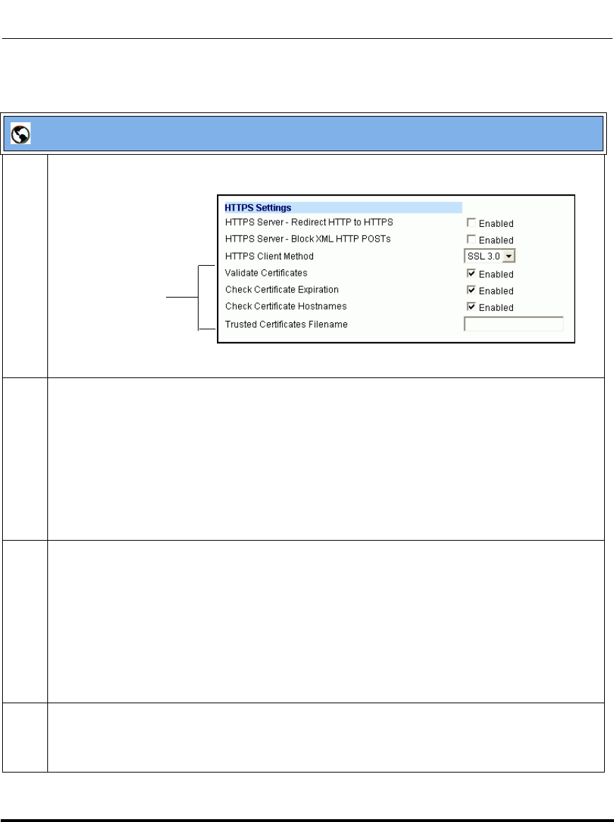
Network Settings
4-48 41-001160-03, Rev 00, Releaes 2.4
IP Phone Administrator Guide
Aastra Web UI
1 Click on Advanced Settings->Network->HTTPS Settings.
2 The “Validate Certificates” field is enabled by default. To disable validation of certificates, click
the check mark in the box to clear the check mark.
When this parameter is enabled, the HTTPS client performs validation on SSL certificates before
accepting them.
Notes:
1. This parameter is immediately applied after clicking the SAVE SETTINGS button.
2. If you are using HTTPS as a configuration method, and use a self signed certificate, you
must disable (uncheck) this field before upgrading to Release 2.3 of the IP Phones.
3 The “Check Certificate Expiration” field is enabled by default. To disable validation of certificate
expiration, click the check mark in the box to clear the check mark.
When this parameter is enabled, the HTTPS client verifies whether or not a certificate has expired
prior to accepting the certificate.
Notes:
1. This parameter is immediately applied after clicking the SAVE SETTINGS button.
2. If the “Check Certificates Expiration” parameter is set to Yes, the clock on the phone must be
set for the phone to accept the certificates.
4 The “Check Certificate Hostnames” field is enabled by default. To disable validation of
hostnames, click the check mark in the box to clear the check mark.
Note: This parameter is immediately applied after clicking the SAVE SETTINGS button.
HTTPS Validation
Certificate
Parameters
Draft 1
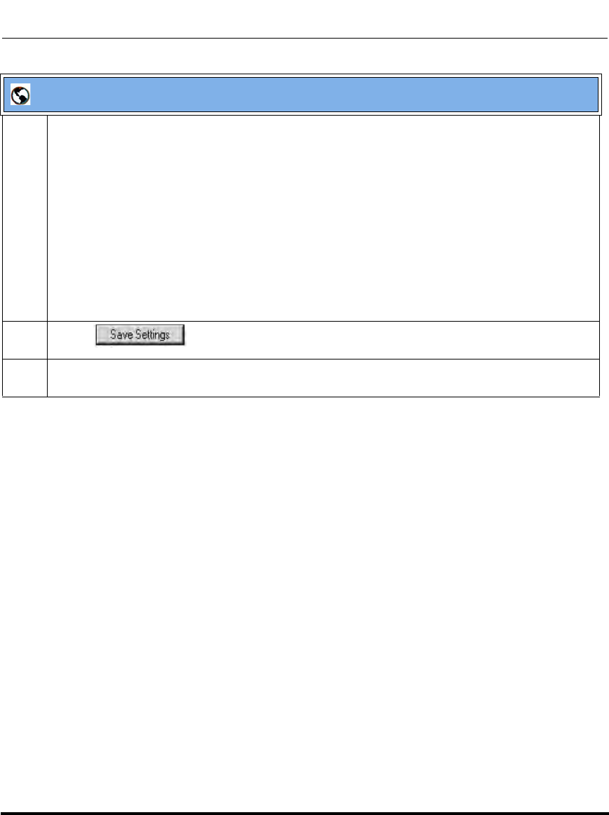
Network Settings
41-001160-03, Rev 00, Releaes 2.4 4-49
Configuring Network and Session Initiation Protocol (SIP) Features
5 If you require the download of User-provided certificates in a .PEM formatted file, enter the file
name in the format <filename.pem> in the “Trusted Certificates Filename” field. For example:
trustedCerts.pem
This parameter specifies a file name for a .PEM file located on the configuration server. This file
contains the User-provided certificates in PEM format. These certificates are used to validate peer
certificates.
Notes:
1. You must disable the “Validate Certificates” field in order for the phone to accept the
User-provided certificates.
2. This parameter requires you restart the phone in order for it to take affect.
6 Click to save your changes.
7 If you entered a filename in the “Trusted Certificates Filename” field, click on Operation->Reset,
and restart the phone for the changes to take affect.
Aastra Web UI
Draft 1

Network Settings
4-50 41-001160-03, Rev 00, Releaes 2.4
IP Phone Administrator Guide
Universal Plug and Play (UPnP) (for remote phones)
UPnP is a standard that uses Internet protocols to enable devices to be plugged
into a network and automatically know about each other. With UPnP, when a user
plugs a device into the network, the device configures itself, acquires a TCP IP
address, and uses a discovery protocol based on the Internet's HTTP or HTTPS
URL to announce its presence on the network to other devices.
This method of device discovery on a network is called “Universal Plug and Play”
or UPnP. If you enable UPnP, and the phone is discovered on the network, port
mappings are set up between the phone and the Internet Gateway Device (IGD).
The phone controls the opening, closing, and polling of ports on the IGD. HTTP
and SIP use a single port each. RTP/RTCP uses a range of ports.
The UPnP manager performs its functions when you set the phone to remote
mode. When you switch the phone back to local mode, the UPnP manager
removes any open port mappings and shuts itself down. If you boot the phone in
remote mode, the UPnP manager initializes after the phone obtains an IP address
and before a SIP registration is sent out. If you want to manually configure your
NAT, you must disable UPnP on the remote mode phone.
You can enable UPnP on remote IP phones using the configuration files, the IP
Phone UI, or the Aastra Web UI. Using the configuration files, you can enable
UPnP using the following parameters:
• upnp manager
• upnp gateway
• sip nat rtp port
The “upnp manager” parameter enables or disables UPnP. The “upnp gateway”
parameter is the IP address or qualified domain name of the Internet gateway or
router that stores the port mappings. In the event a phone using UPnP is rebooted,
it will still have the previously set port mappings on the gateway. The “sip nat rtp
port” parameter specifies the RTP port range on the gateway.
Note: Enabling UPnP allows the IP phones to access the Internet even if
a firewall has been set on the IGD. This allows the phone to send and
receive SIP calls and XML pushes without interruption. UPnP does not
work with multiple firewalls.
Draft 1
Network Settings
41-001160-03, Rev 00, Releaes 2.4 4-51
Configuring Network and Session Initiation Protocol (SIP) Features
A User or Administrator can specify UPnP on specific lines using the
configuration files (using the “upnp mapping lines” parameter) or the Aastra
Web UI (at the path Basic Settings->Preferences->UPnP Mapping Lines).
Reference
For more information about enabling/disabling UPnP Mapping on specific lines,
see Chapter 5, the section, “UPnP Mapping Lines (for remote phones)” on
page 5-87.
Configuring UPnP (optional)
Use the following procedures to configure UPnP on the IP phones.
Configuration Files
For specific parameters you can set in the configuration files, see Appendix A, the section, “UPnP Settings”
on page A-37.
IP Phone UI
Step Action
1 Press on the phone to enter the Options List.
2Select Administrator Menu.
3 Enter your Administrator password.
Note: The IP Phones accept numeric passwords only.
4Select Network Settings.
5Select NAT Settings.
6Select UPnP.
7 Press Change to select “Yes” or “No”. Default is “No”.
This field enables or disables the use of UPnP on the IP Phone.
Draft 1
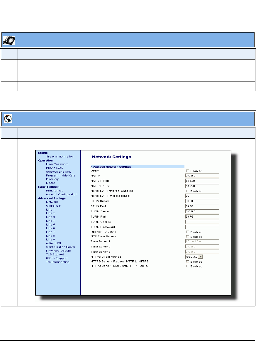
Network Settings
4-52 41-001160-03, Rev 00, Releaes 2.4
IP Phone Administrator Guide
.
8 Press Done (3 times) to save the changes.
Note: The session prompts you to restart the IP phone to apply the configuration settings
9Select Restart.
Aastra Web UI
Step Action
1 Click on Advanced Settings->Network->Advanced Network Settings.
IP Phone UI
Step Action
Draft 1

Network Settings
41-001160-03, Rev 00, Releaes 2.4 4-53
Configuring Network and Session Initiation Protocol (SIP) Features
2The “UPnP” field is disabled by default. To enable UPnP, place a check in the “Enabled” box.
Uncheck the box to disable this field. This field enables and disable UPnP on the IP phone.
3 Click to save your settings.
Aastra Web UI
Step Action
Draft 1
Network Settings
4-54 41-001160-03, Rev 00, Releaes 2.4
IP Phone Administrator Guide
Virtual LAN (optional)
Virtual Local Area Network (VLAN) is a feature on the IP phone that allows for
multiple logical Ethernet interfaces to send outgoing RTP packets over a single
physical Ethernet as described in IEEE Std 802.3. On the IP phone, you configure
a VLAN ID that associates with the physical Ethernet port.
By configuring specific VLAN parameters, the IP phones have the capability of
adding and removing tags, and processing the ID and priority information
contained within the tag.
VLAN on the IP phones is disabled by default. When you enable VLAN, the IP
phone provides defaults for all VLAN parameters. If you choose to change these
parameters, you can configure them using the configuration files, the IP Phone UI,
or the Aastra Web UI.
The following sections describe the VLAN features you can configure on the IP
phones.
Type of Service (ToS), Quality of Service (QoS), and DiffServ QoS
ToS is an octet as a field in the standard IP header. It is used to classify the traffic
of the different QoSs.
QoS provides service differentiation between IP packets in the network. This
service differentiation is noticeable during periods of network congestion (for
example, in case of contention for resources) and results in different levels of
network performance.
Port 0 is the Ethernet LAN Port connected to the network. Port 1 is the Ethernet
PC Port used for passthrough to a PC.
Differentiated Service (DiffServ) QoS is class-based where some classes of traffic
receive preferential handling over other traffic classes.
The Differentiated Services Code Point (DSCP) value is stored in the first six bits
of the ToS field. Each DSCP specifies a particular per-hop behavior that is
applied to a packet.
Note: All latest VLAN functionality is backwards compatible with IP
Phone Releases 1.3 and 1.3.1.
Draft 1
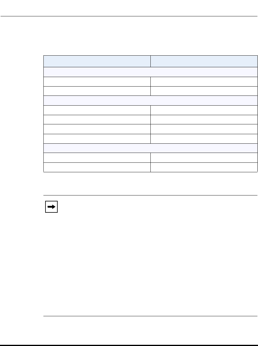
Network Settings
41-001160-03, Rev 00, Releaes 2.4 4-55
Configuring Network and Session Initiation Protocol (SIP) Features
The following parameters allow an administrator to configure ToS, QoS, and
DiffServ QoS for VLAN:
Parameters in Configuration Files Parameters in Aastra Web UI
Global
tagging enabled VLAN enable
priority non-ip Priority, Non-IP Packet
LAN Port
vlan id VLAN ID
tos priority map SIP Priority
tos priority map RTP Priority
tos priority map RTCP Priority
PC Port
vlan id port 1 VLAN ID
QoS eth port 1 priority Priority
Notes:
1. In order for the software to successfully maintain connectivity with a
network using VLAN functionality, the IP phone reboots if you modify
the "tagging enabled" (VLAN Enable in the Web UI), "vlan id", or
"vlan id port 1" parameters.
2. When the LAN Port (vlan id) and the PC Port (vlan id port 1)
parameters have the same value, VLAN functionality is compatible with
earlier IP phone software releases.
If you set the PC Port (vlan id port 1) to 4095, all untagged packets are
sent to this port. For configuring this feature via the Phone UI and the
Aastra Web UI, see “Configuring VLAN (optional)” on page 4-60. For
configuring this feature using the configuration files, see Appendix A, the
section, “Virtual Local Area Network (VLAN) Settings” on page A-38.
Draft 1

Network Settings
4-56 41-001160-03, Rev 00, Releaes 2.4
IP Phone Administrator Guide
DSCP Range/VLAN Priority Mapping
DSCP bits in the ToS field of the IP header are set for RTP, RTCP, and SIP packets
using either the default values or the values configured via the "tos sip", "tos rtp",
and "tos rtcp" parameters.
When the VLAN global configuration parameter, "tagging enabled" is set to 1,
VLAN priority for IP packets is mapped to the DSCP value instead of a single
priority for all packets. An administrator can also configure VLAN priority for
non-IP packets using the "priority non-ip" parameter.
Since the default DSCP settings for SIP, RTP, and RTCP are 26, 46, and 46
respectively, this results in corresponding default VLAN priorities of 3 for SIP, 4
for RTP, and 4 for RTCP (based on the settings in the table “DSCP Range/VLAN
Priority” on page 4-56).
You can change the default parameters by modifying just the DSCP values, just
the VLAN priority values, or by modifying all values.
The following table shows the DSCP range/VLAN priority mapping.
DSCP Range/VLAN Priority
DSCP
Range VLAN Priority
0-7 0
8-15 1
16-23 2
24-31 3
32-39 4
40-47 5
48-55 6
56-63 7
Draft 1
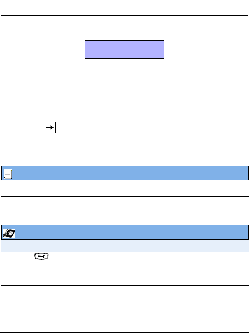
Network Settings
41-001160-03, Rev 00, Releaes 2.4 4-57
Configuring Network and Session Initiation Protocol (SIP) Features
The following table identifies the default DSCP of protocols.
Configuring Type of Service (ToS)/DSCP (optional)
Use the following procedures to configure ToS/DSCP on the IP phone.
Protocol
Name Default DSCP
Values in the
ToS Field
sip 26
rtp 46
rtcp 46
Note: ToS/DSCP is enabled by default. The SIP, RTP, and RTCP
parameters show defaults of 26, 46, and 46, respectively. Use the
following procedures to change these settings if required.
Configuration Files
For specific parameters you can set in the configuration files, see Appendix A, the section, “Type of Service
(ToS)/DSCP Settings” on page A-44.
IP Phone UI
Step Action
1 Press on the phone to enter the Options List.
2Select Administrator Menu.
3 Enter your Administrator password.
Note: The IP Phones accept numeric passwords only.
4Select Network Settings.
5Select Type of Service DSCP.
Draft 1

Network Settings
4-58 41-001160-03, Rev 00, Releaes 2.4
IP Phone Administrator Guide
6Select Type of Service SIP.
or
Select Type of Service RTP.
or
Select Type of Service RTCP.
7 Enter a value for “Type of Service SIP”. Default is 26.
or
Enter a value for “Type of Service RTP”. Default is 46.
or
Enter a value for “Type of Service RTCP”. Default is 46.
Valid values are 0 to 63.
Note: If you change the ToS/DSCP setting for a Protocol, and VLAN is enabled, you will need to map
the applicable priority to the Protocol setting as shown in the table “DSCP Range/VLAN Priority” on
page 4-56 For more information, see the section “Configuring VLAN (optional)” on page 4-60.
8 Press Done (3 times) to save the changes.
Note: The session prompts you to restart the IP phone to apply the configuration settings
9Select Restart.
IP Phone UI
Step Action
Draft 1
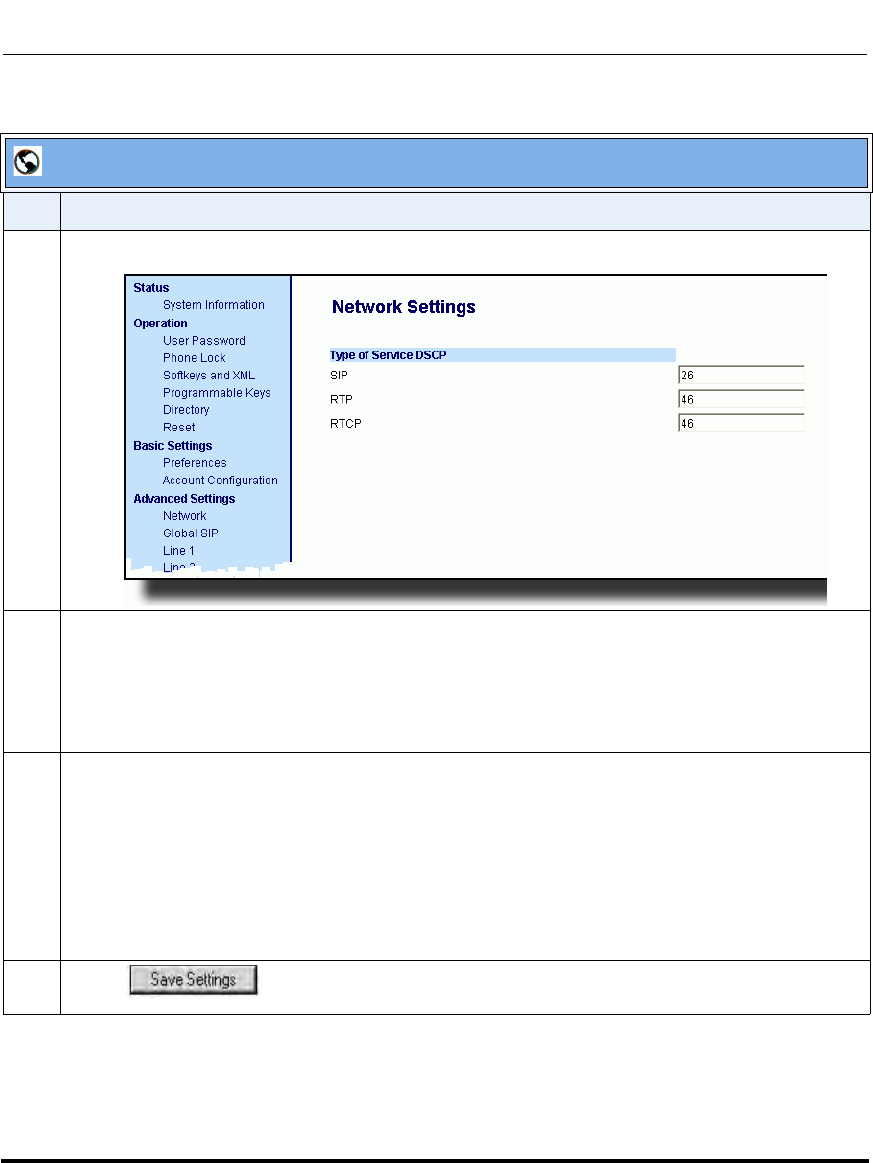
Network Settings
41-001160-03, Rev 00, Releaes 2.4 4-59
Configuring Network and Session Initiation Protocol (SIP) Features
.
Aastra Web UI
Step Action
1 Click on Advanced Settings->Network->Type of Service,DSCP.
2 Select a Protocol field:
•“SIP”
or
•“RTP”
or
•“RTCP”
3 Enter a value from 0 to 63. Default values are as follows:
SIP = 26
RTP = 46
RTCP = 46
Note: If you change the ToS/DSCP setting for a Protocol, and VLAN is enabled, you will need to map
the applicable priority to the Protocol setting as shown in the table “DSCP Range/VLAN Priority” on
page 4-60 For more information, see the section “Configuring VLAN (optional)” on page 4-60.
4 Click to save your settings.
Draft 1
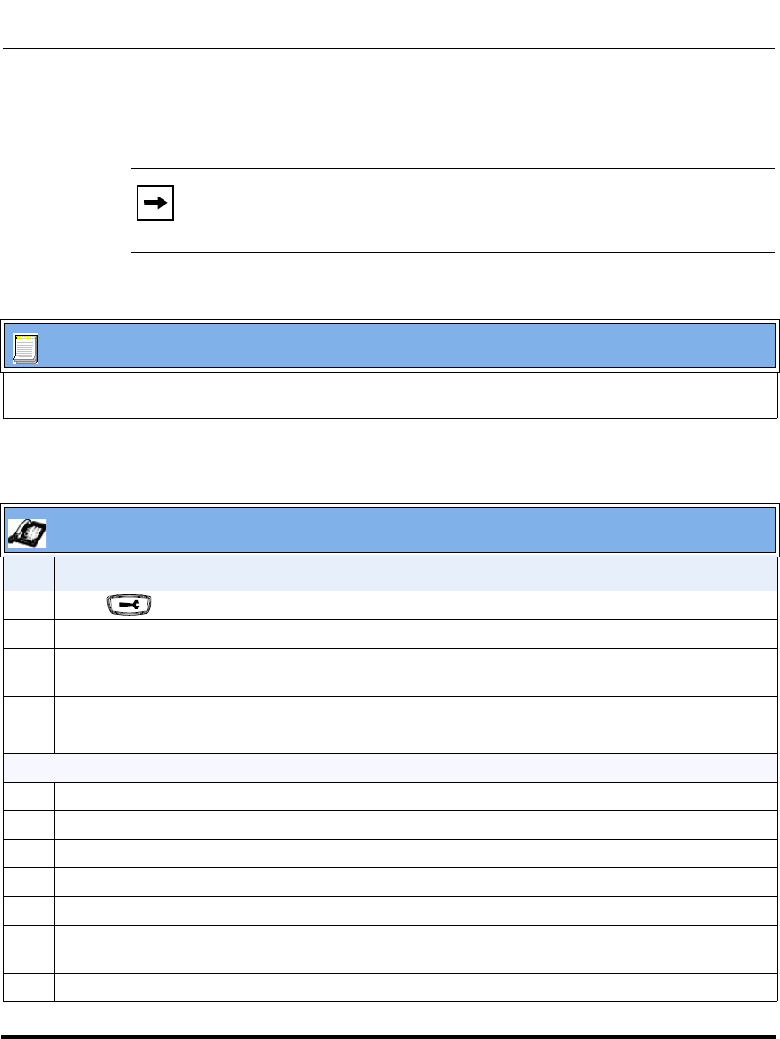
Network Settings
4-60 41-001160-03, Rev 00, Releaes 2.4
IP Phone Administrator Guide
Configuring VLAN (optional)
Use the following procedures to configure VLAN on the IP phone.
Note: VLAN is disabled by default. When you enable VLAN, the IP
phones use the default settings for each VLAN parameter. You can
change the default settings if required using the following procedure.
Configuration Files
For specific parameters you can set in the configuration files, see Appendix A, the section, “Virtual Local
Area Network (VLAN) Settings” on page A-38.
IP Phone UI
Step Action
1 Press on the phone to enter the Options List.
2Select Administrator Menu.
3 Enter your Administrator password.
Note: The IP Phones accept numeric passwords only.
4Select Network Settings.
5Select VLAN Settings.
To globally enable/disable VLAN and set priority for non-IP packets:
6Select VLAN Enable.
7 Press Change to set VLAN Enable to “Yes” to enable or “No” to disable. Default is “No”.
8 Press Done to save the changes.
9Select Phone VLAN.
10 Select VLAN Priority.
11 Select Other and enter a non-IP priority value from 0 to 7 for non-IP packets.
Default for this field is 5.
12 Press Done (3 times) to return to the VLAN Settings menu.
Draft 1

Network Settings
41-001160-03, Rev 00, Releaes 2.4 4-61
Configuring Network and Session Initiation Protocol (SIP) Features
To set VLAN ID and priority for LAN Port (Port 0):
13 Select Phone VLAN.
14 Select Phone VLAN ID and enter a value from 1 to 4094 to specify the VLAN ID for the LAN Port.
Default is 1.
15 Press Done to save the change.
16 Select VLAN Priority.
17 Select one of the following VLAN Protocols:
• SIP Priority
• RTP Priority
• RTCP Priority
18 Enter a VLAN priority value from 0 to 7 for the associated Protocol. Default values for each Protocol
are:
SIP Priority = 3
RTP Priority = 5
RTCP Priority = 5
19 Press Done (3 times) to return to the VLAN Settings menu.
To set VLAN ID and priority for PC Port (Port 1):
20 Select PC Port VLAN.
21 Select PC Port VLAN ID.
22 Enter a value from 1 to 4095 to specify the VLAN ID for the PC Port.
Default is 1.
Note: If you set the PC Port VLAN ID (Port 1) to 4095, all untagged packets are sent to this port. The
following is an example of configuring the phone on a VLAN where all untagged packets are sent to
the PC Port (passthrough port).
Example
You enable tagging on the phone port as normal but set the passthrough port (PC Port) to
4095. The following example sets the phone to be on VLAN 3 but the passthrough port is
configured as untagged.
VLAN Settings->VLAN Enable: Yes
VLAN Settings->Phone VLAN->Phone VLAN ID: 3
VLAN Settings->PC Port VLAN->PC Port VLAN ID: 4095
IP Phone UI
Step Action
Draft 1
Network Settings
4-62 41-001160-03, Rev 00, Releaes 2.4
IP Phone Administrator Guide
23 Press Done to save the change.
24 Select PC Port Priority.
25 Select a PC Port VLAN priority value from 0 to 7 for the PC Port.
Default is 0.
26 Press Done (4 times) to save the changes.
Note: The session prompts you to restart the IP phone to apply the configuration settings
27 Select Restart.
IP Phone UI
Step Action
Draft 1
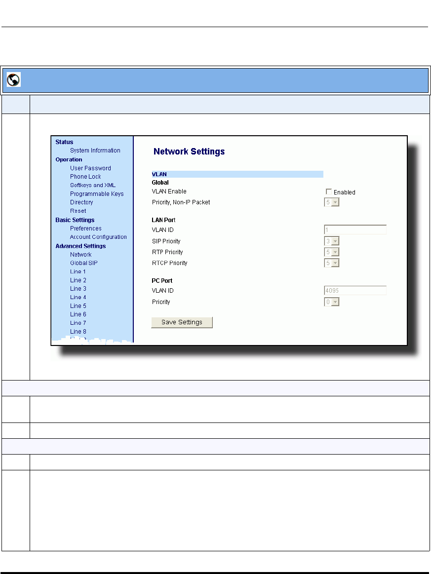
Network Settings
41-001160-03, Rev 00, Releaes 2.4 4-63
Configuring Network and Session Initiation Protocol (SIP) Features
.
Aastra Web UI
Step Action
1 Click on Advanced Settings->Network->VLAN.
To globally enable/disable VLAN and set priority for non-IP packets:
2 Enable VLAN by checking the VLAN Enable field check box. (Disable this field by unchecking the
check box).
3 With VLAN enabled, select the priority (0 to 7) for non-IP packets in the Priority, Non-IP Packet field.
To set VLAN ID and priority for the LAN Port (Port 0):
4 Enter a VLAN ID value from 1 to 4094 in the VLAN ID field. Default is 1.
5 Choose a VLAN Protocol (SIP Priority, RTP Priority, and/or RTCP Priority), and select a priority for
the associated Protocol. Valid values are 0 to 7, Defaults are as follows:
SIP Priority = 3
RTP Priority = 5
RTCP Priority = 5
Draft 1
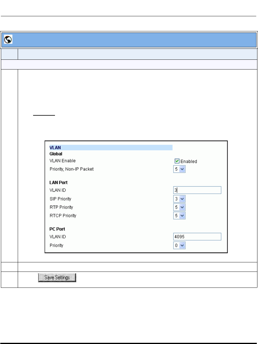
Network Settings
4-64 41-001160-03, Rev 00, Releaes 2.4
IP Phone Administrator Guide
To set VLAN ID and priority for the PC Port (Port 1):
6 Enter a VLAN ID value from 1 to 4095 in the VLAN ID field. Default is 1.
Note: If you set the PC Port VLAN ID (Port 1) to 4095, all untagged packets are sent to this PC Port.
The following is an example of configuring the phone on a VLAN where all untagged packets are sent
to the passthrough port.
Example
You enable tagging as normal, enter a value for the LAN Port VLAN ID, and then set the PC
Port VLAN ID to 4095. The following example sets the phone to be on VLAN 3 but the PC Port
VLAN ID is configured as untagged..
7 Select a VLAN priority value from 0 to 7 for the PC Port in the Priority field. Default is 0.
8 Click to save your settings.
Aastra Web UI
Step Action
Draft 1
Network Settings
41-001160-03, Rev 00, Releaes 2.4 4-65
Configuring Network and Session Initiation Protocol (SIP) Features
RPORT
The Session Initiation Protocol (SIP) operates over UDP and TCP. When used
with UDP, responses to requests are returned to the source address from which the
request came, and returned to the port written into the topmost “Via” header of the
request. However, this behavior is not desirable when the client is behind a
Network Address Translation (NAT) or firewall.
A parameter created for the “Via” header called “Rport” in RFC 3581, allows a
client to request that the server send the response back to the source IP address
and the port from which the request came.
When you enable “Rport, the phone always uses symmetric signaling (listens on
the port used for sending requests).
An Administrator can configure “Rport” using the configuration files or the
Aastra Web UI.
Configuring Rport Using the Configuration Files
Use the following parameter to configure Rport on your phone.
sip rport
Configuration Files
For specific parameters you can set in the configuration files, see Appendix A, the section, “Rport Setting” on
page A-31.
Draft 1
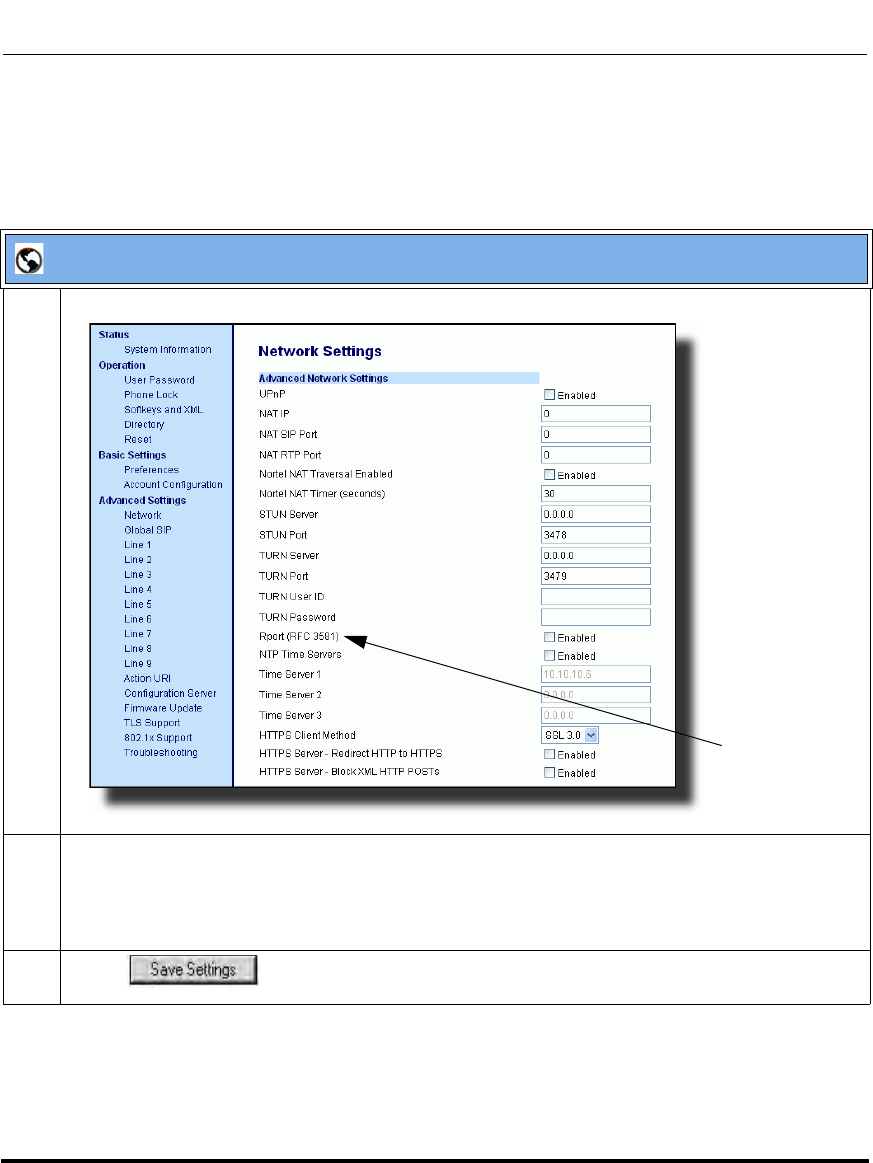
Network Settings
4-66 41-001160-03, Rev 00, Releaes 2.4
IP Phone Administrator Guide
Configuring Rport Using the Aastra Web UI
Use the following procedure to configure Rport on your phone using the Aastra
Web UI.
Aastra Web UI
1 Click on Advanced Settings->Network->Advanced Network Settings.
2 In the "Advanced Network Settings" section, enable the "Rport (RFC3581" field by checking the
check box. (Disable Rport by unchecking the box).
“Rport” in RFC 3581, allows a client to request that the server send the response back to the source
IP address and the port from which the request came.
3 Click to save your changes.
Rport
Parameter
Draft 1
Network Settings
41-001160-03, Rev 00, Releaes 2.4 4-67
Configuring Network and Session Initiation Protocol (SIP) Features
Network Time Servers
Network Time Protocol (NTP) is a protocol that the IP phone uses to synchronize
the phone clock time with a computer (configuration server) in the network.
To use NTP, you must enable it using the configuration files or the Aastra Web UI.
You can specify up to three time servers in your network.
Configuring NTP Servers (optional)
Use the following procedure to enable/disable and configure the NTP servers
using the configuration files.
Use the following procedure to enable/disable the NTP server using the IP Phone
UI.
Note: The IP phones support NTP version 1.
Configuration Files
For specific parameters you can set in the configuration files, see Appendix A, the section, “Time Server
Settings” on page A-52.
IP Phone UI
Step Action
1 Press on the phone to enter the Options List.
2Select Preferences.
3Select Time and Date.
4Select Time Server.
5 Enter your Administrator password.
Note: The IP Phones accept numeric passwords only.
6Select Timer Server 1, Timer Server 2, or Time Server 3.
Note: The Time Servers are disabled by default.
7 To set a Time Server, press Enable. (Press Disable to disable a Time Server.)
Draft 1
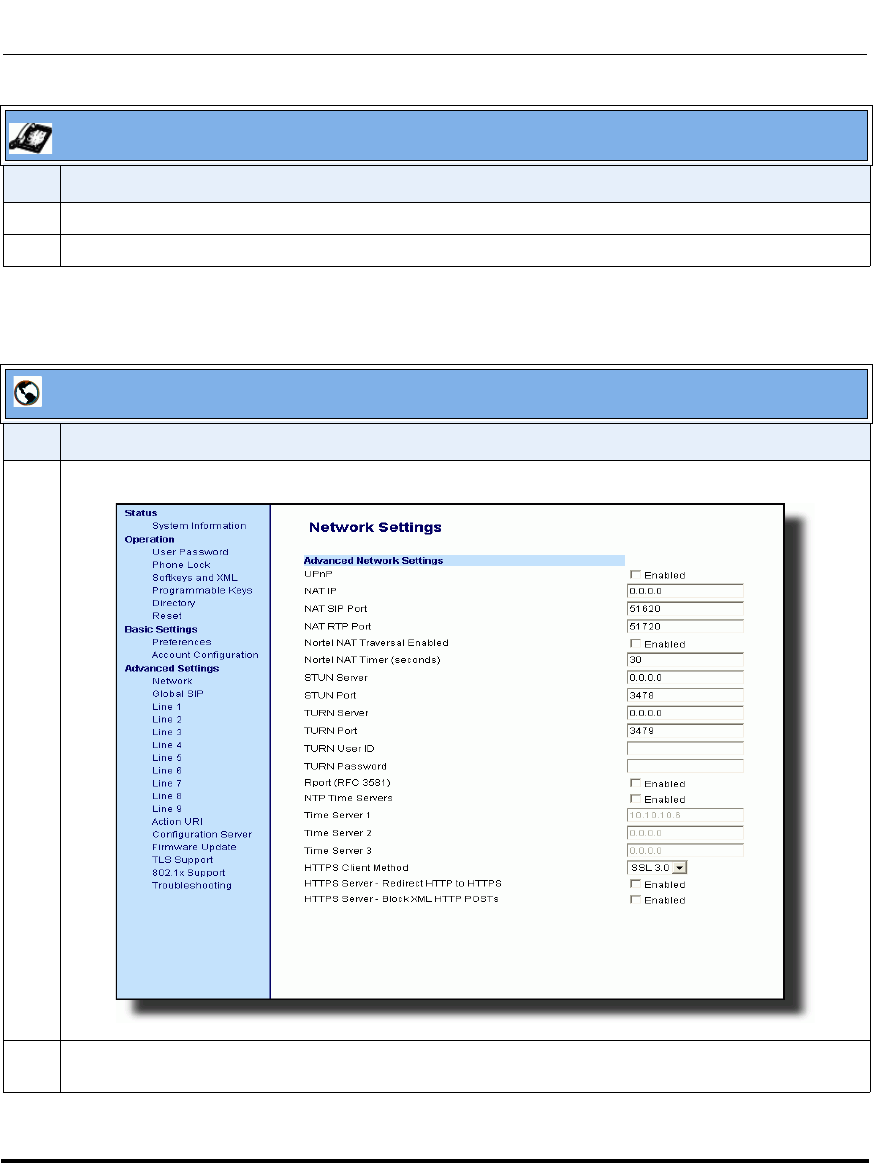
Network Settings
4-68 41-001160-03, Rev 00, Releaes 2.4
IP Phone Administrator Guide
Use the following procedure to enable/disable and configure the NTP Servers
using the Aastra Web UI.
8 Enter the IP Address (in dotted decimal) or qualified domain name for the Time Server.
9 Press Done to save the change.
Aastra Web UI
Step Action
1 Click on Advanced Settings->Network->Advanced Network Settings.
2 Enable the "NTP Time Servers" field by checking the check box.
(Disable this field by unchecking the box). Default is disabled.
IP Phone UI
Step Action
Draft 1

Network Settings
41-001160-03, Rev 00, Releaes 2.4 4-69
Configuring Network and Session Initiation Protocol (SIP) Features
3 Enter an IP address or qualified domain name in the "Time Server 1", "Time Server 2", and/or
"Time Server 3" field(s) to specify the location of the NTP time server.
4 Click to save your changes.
Aastra Web UI
Step Action
Draft 1

Global SIP Settings
4-70 41-001160-03, Rev 00, Releaes 2.4
IP Phone Administrator Guide
Global SIP Settings
Description
The IP phone uses the information in the Global Session Initiation Protocol (SIP)
settings to register at the IP PBX.
The IP phone configuration defines network and user account parameters that
apply globally to all SIP lines. Since not all SIP lines are necessarily hosted using
the same IP-PBX/server or user account, additional sets of per-line parameters
can also be defined for network and user account.
You configure and modify these parameters and associated values using the
configuration files, the IP phone UI, or the Aastra Web UI. The Aastra Web UI
and configuration file methods configure global and per-line SIP settings on the IP
phone. The IP phone UI configures global SIP settings only.
On the IP Phones, you can configure Basic and Advanced SIP Settings. The Basic
SIP Settings include authentication and network settings. The Advanced SIP
Settings include other features you can configure on the IP Phone.
Reference
For more information about Basic SIP Settings (for authentication and network),
see “Basic SIP Settings” on page 4-71.
For more information bout Advanced SIP Settings, see “Advanced SIP Settings
(optional)” on page 4-84.
Draft 1

Global SIP Settings
41-001160-03, Rev 00, Releaes 2.4 4-71
Configuring Network and Session Initiation Protocol (SIP) Features
Basic SIP Settings
Specific parameters are configurable on a global and per-line basis. You can also
configure specific parameters using the IP Phone UI, the Aastra Web UI, or the
configuration files. If you have a proxy server or have a SIP registrar present at a
different location than the PBX server, the SIP parameters may need to be
changed.
The IP phones allow you to define different SIP lines with the same account
information (i.e., same user name) but with different registrar and proxy IP
addresses. This feature works with Registration, Subscription, and Notify
processing. This feature also works with the following types of calls: incoming,
outgoing, Broadsoft Shared Call Appearance (SCA), Bridged Line Appearance
(BLA), conference, transfer, blind transfer.
The following tables identify the SIP global and per-line, authentication and
network parameters on the IP phones.
SIP Global Parameters
IP Phone UI Parameters Aastra Web UI Parameters Configuration File Parameters
SIP Global Authentication Parameters
• Screen Name
•N/A
• User Name
• Display Name
• Auth Name
• Password
•N/A
•N/A
• Screen Name
• Screen Name 2
• Phone Number
• Caller ID
• Authentication Name
• Password
•BLA Number
• Line Mode
• sip screen name
• sip screen name 2
• sip user name
• sip display name
• sip auth name
• sip password
• sip bla number
• sip mode
• sip vmail
SIP Global Network Parameters
• Proxy Server
• Proxy Port
•N/A
•N/A
•N/A
•N/A
• Registrar Server
• Registrar Port
•N/A
•N/A
•N/A
•N/A
• Proxy Server
• Proxy Port
• Backup Proxy Server
• Backup Proxy Port
• Outbound Proxy Server
• Outbound Proxy Port
• Registrar Server
• Registrar Port
• Backup Registrar Server
• Backup Registrar Port
• Registration Period
• Conference Server URI
(see Chapter 5)
• sip proxy ip
• sip proxy port
• sip backup proxy ip
• sip backup proxy port
• sip outbound proxy
• sip outbound proxy port
• sip registrar ip
• sip registrar port
• sip backup registrar ip
• sip backup registrar port
• sip registration period
• sip centralized conf
• (see Chapter 5)
Draft 1

Global SIP Settings
4-72 41-001160-03, Rev 00, Releaes 2.4
IP Phone Administrator Guide
Reference
For more information about centralized conferencing, see Chapter 5, the section,
“Centralized Conferencing (for Sylantro and Broadsoft Servers)” on page 5-359.
SIP Per-Line Parameters
Reference
For more information about centralized conferencing, see Chapter 5, the section,
“Centralized Conferencing (for Sylantro and Broadsoft Servers)” on page 5-359.
IP Phone UI Parameters Aastra Web UI Parameters Configuration File Parameters
SIP Per-Line Authentication Parameters
• Screen Name
•N/A
• User Name
• Display Name
• Auth Name
• Password
•N/A
•N/A
• Screen Name
• Screen Name 2
• Phone Number
• Caller ID
• Authentication Name
• Password
•BLA Number
• Line Mode
• sip lineN screen name
• sip lineN screen name 2
• sip lineN user name
• sip lineN display name
• sip lineN auth name
• sip lineN password
• sip lineN bla number
• sip lineN mode
• sip lineN vmail
SIP Per-Line Network Parameters
• Proxy Server
• Proxy Port
•N/A
•N/A
•N/A
•N/A
• Registrar Server
• Registrar Port
•N/A
•N/A
•N/A
•N/A
• Proxy Server
• Proxy Port
• Backup Proxy Server
• Backup Proxy Port
• Outbound Proxy Server
• Outbound Proxy Port
• Registrar Server
• Registrar Port
• Backup Registrar Server
• Backup Registrar Port
• Registration Period
• Conference Server URI
•(see Chapter 5)
• sip lineN proxy ip
• sip lineN proxy port
• sip lineN backup proxy ip
• sip lineN backup proxy port
• sip lineN outbound proxy
• sip lineN outbound proxy port
• sip lineN registrar ip
• sip lineN registrar port
• sip lineN backup registrar ip
• sip lineN backup registrar port
• sip lineN registration period
• sip lineN centralized conf
•(see Chapter 5)
Draft 1

Global SIP Settings
41-001160-03, Rev 00, Releaes 2.4 4-73
Configuring Network and Session Initiation Protocol (SIP) Features
Specific sets of SIP parameters are inter-dependent with each other. To prevent
conflicting parameter values from being applied, per-line values always take
precedence over the corresponding set of global values.
For example, if a parameter value is configured for one of the per-line sets, all
parameters from that set are applied and all parameters from the corresponding
global section are ignored, even if some of the parameters within the global set are
not defined in the per-line set.
SIP Precedence Example
The following example shows the SIP proxy feature and example schema for
storage and parsing of the SIP configuration parameters.
The following SIP configuration is assumed:
# SIP network block
sip proxy ip: 10.30.11.154
sip proxy port: 5060
sip registrar ip: 10.44.122.37
sip registrar port: 4020
sip line3 proxy ip: siparator.vonage.com
sip line3 proxy port: 0
Note: The "sip vmail" and "sip lineN vmail" parameters are configurable
using the configuration files only. To configure voicemail see Chapter 5,
the section, “Voicemail (9480i, 9480i CT, 6755i, 6757i, and 6757i CT
only)” on page 5-308.
Draft 1
Global SIP Settings
4-74 41-001160-03, Rev 00, Releaes 2.4
IP Phone Administrator Guide
Line3 specifies per-line values for proxy IP address and proxy port, so the phone
uses those parameter values for SIP calls made on that line. However, because
those parameters are part of the SIP network block, the phone does not apply any
of the global SIP network block parameters. So even though the global parameters
configure a SIP registrar, Line3 on the phone ignores all global network block
parameters. Since line3 does not contain a per-line SIP registrar entry, the phone
does not use a registrar for that line.
Note: Global SIP parameters apply to all lines unless overridden by a
per-line configuration.
Per-line settings are configurable for lines 1 through 7.
Draft 1

Global SIP Settings
41-001160-03, Rev 00, Releaes 2.4 4-75
Configuring Network and Session Initiation Protocol (SIP) Features
Backup Proxy/Registrar Support
The IP phones support a backup SIP proxy and backup SIP registrar feature. If
the primary server is unavailable, the phone automatically switches to the backup
server allowing the user's phone to remain in service.
How it Works
All SIP registration messages are sent to the primary registrar first. If the server is
unavailable, then a new registration request is sent to the backup registrar. This
also applies to registration renewal messages, which try the primary server before
the backup.
Similarly, any outgoing calls attempt to use the primary proxy first, then the
backup if necessary. In addition, subscriptions for BLF, BLA, and explicit MWI
can also use the backup proxy when the primary fails. Outgoing calls and the
previously mentioned subscriptions behave the same as registrations, where the
primary proxy is tried before the backup.
You can configure the backup SIP proxy on a global or per-line basis via the
configuration files or the Aastra Web UI.
SIP Server (SRV) Lookup
The SIP SRV Lookup feature allows you to configure the IP phone to perform a
DNS server lookup on a SIP proxy, a SIP registrar, or a SIP outbound proxy.
The IP phone performs an SRV lookup when the IP address of the server is FQDN
and the corresponding port is 0.
For example, if the phone is configured with sip proxy ip of "ana.aastra.com",
and sip proxy port of "0", the SRV lookup may return multiple servers, based on
the priorities if one is selected as primary and others are selected as secondary.
However, if the IP address is an FQDN and the corresponding server port is
non-zero, then the phone performs a DNS "A" Name Query to resolve the FQDN
into dot notation form.
If the IP address is a valid dot notation and the port is zero, then a default port
5060 is used.
Draft 1
Global SIP Settings
4-76 41-001160-03, Rev 00, Releaes 2.4
IP Phone Administrator Guide
You can configure SRV lookup using the configuration files (aastra.cfg and
<mac>.cfg) only. The parameters to use are:
• sip proxy ip
• sip proxy port
Configuring Basic SIP Network Settings (optional)
You can configure SIP settings using the configuration files, the IP Phone UI, or
the Aastra Web UI.
Note: To configure the SIP settings per-line, use the configuration files or
the Aastra Web UI.
Configuration Files
For specific parameters you can set in the configuration files, see Appendix A, the section, “SIP Basic,
Global Settings” on page A-67 or “SIP Basic, Per-Line Settings” on page A-76
Note: You can set global configuration only using the IP Phone UI.
Draft 1

Global SIP Settings
41-001160-03, Rev 00, Releaes 2.4 4-77
Configuring Network and Session Initiation Protocol (SIP) Features
IP Phone UI
Step Action
1 Press on the phone to enter the Options List.
2Select Administrator Menu.
3 Enter your Administrator password.
Note: The IP Phones accept numeric passwords only.
4Select SIP Settings.
Configuring Proxy IP and Proxy Port
5Select Proxy IP/Port.
6Enter an IP address or fully qualified host name in the Proxy Server field. Default is 0.0.0.0.
7Enter a Proxy Port number in the Proxy Port field for accessing the SIP proxy server.
Default is 0.
8Press Done to save the changes.
Configuring Registrar IP and Registrar Port
9Select Registrar IP/Port.
10 Enter an IP address or fully qualified host name in the Registrar Server field. Default is 0.0.0.0.
A global value of 0.0.0.0 disables registration. However, the phone is still active and you can dial
using username@ip address of the phone.
If the Registrar IP address is set to 0.0.0.0 for a per-line basis (i.e, line 1, line 2, etc.), then the
register request is not sent, the "No Service" message does not display, and the message waiting
indicator (MWI) does not come on.
11 Enter a Registrar Port number in the Registrar Port field for accessing the SIP registrar server.
Default is 0.
12 Press Done to save the changes.
Enabling/Disabling the Use of the Registrar Server
13 Select SIP Register.
14 Press Change to set Register to "Yes" (enable) or "No" (disable). Default is “Yes”.
This parameter enables/disables the IP phone to register on the network.
15 Press Done to save the changes.
Draft 1

Global SIP Settings
4-78 41-001160-03, Rev 00, Releaes 2.4
IP Phone Administrator Guide
16 Select User Name to enter the username in the name field of the SIP URI for the IP phone, and for
registering the phone at the registrar.
Note: The IP phones allow usernames containing dots (“.”). You can also enter the same user name
for different registrar and proxy IP addresses.
17 Press Done to save the changes.
18 Select Display Name to enter the name used in the display name field of the "From SIP" header
field.
19 Press Done to save the changes.
20 Select Screen Name and enter the name to display on the idle screen.
21 Press Done to save the changes.
22 Select Authentication Name to enter the authorization name used in the username field of the
Authorization header field of the SIP REGISTER request.
23 Press Done to save the changes.
24 Select Password to enter the password used to register the IP phone with the SIP proxy.
Note: The IP phones accept numeric passwords only.
25 Press Done (3 times) to save the changes.
Note: The session prompts you to restart the IP phone to apply the configuration settings
26 Select Restart.
IP Phone UI
Step Action
Draft 1
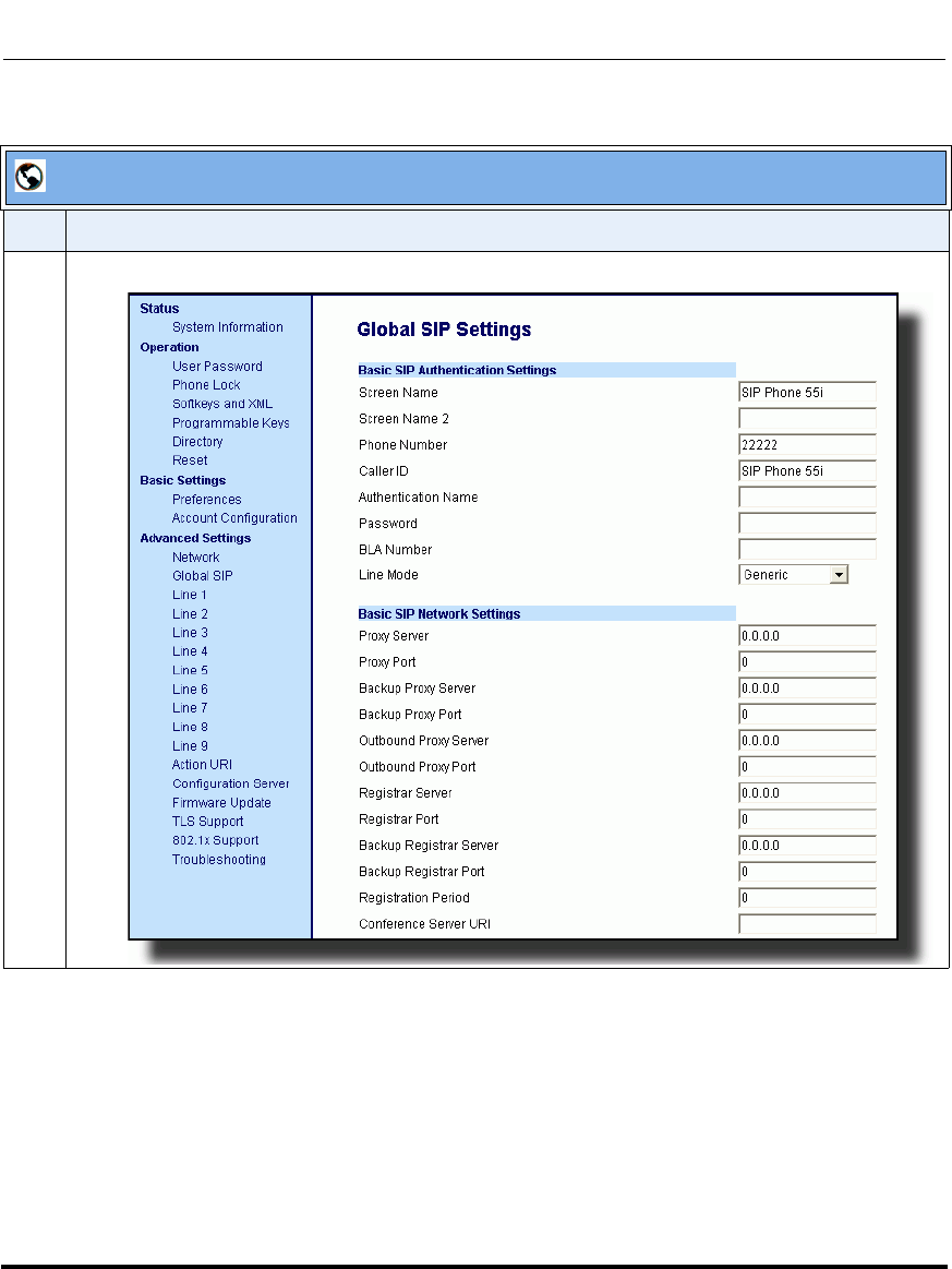
Global SIP Settings
41-001160-03, Rev 00, Releaes 2.4 4-79
Configuring Network and Session Initiation Protocol (SIP) Features
.
Aastra Web UI
Step Action
1 For global configuration, click on Advanced Settings->Global SIP->Basic SIP Settings.
Draft 1
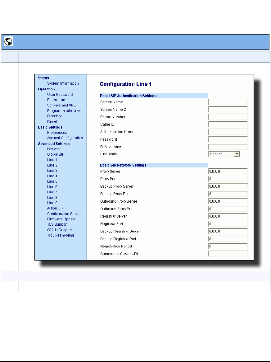
Global SIP Settings
4-80 41-001160-03, Rev 00, Releaes 2.4
IP Phone Administrator Guide
Or, for per-line configuration, click on Advanced Settings->Line N (1-9).
To configure SIP authentication settings:
2 In the "Screen Name" field, enter the screen name that displays on the idle screen.
Aastra Web UI
Step Action
Draft 1
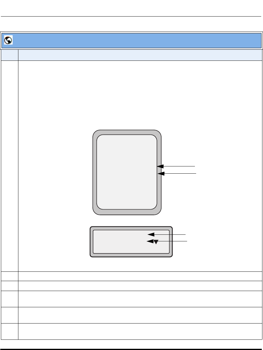
Global SIP Settings
41-001160-03, Rev 00, Releaes 2.4 4-81
Configuring Network and Session Initiation Protocol (SIP) Features
3 In the "Screen Name 2" field, enter the text you want to display on the phone under the “Screen
Name” on the idle screen.
Notes:
1. If other status messages display on the phone, such as “Network Disconnected”, the Screen
Name 2 value does not display.
2. Symbol characters are allowed (such as “#”).
3. If the text is longer than the display width, than the display truncates the text to fit the display.
4 In the "Phone Number" field, enter the phone number of the IP phone.
5 In the "Caller ID" field, enter the phone number of the IP phone.
6 In the "Authentication Name" field, enter the name used in the username field of the Authorization
header of the SIP REGISTER request.
7 In the "Password" field, enter the password used to register the IP phone with the SIP proxy.
Note: The IP phones accept numeric passwords only.
8 In the "BLA Number" field, enter the Bridge Line Appearance (BLA) number to be shared across all
IP phones.
Aastra Web UI
Step Action
Services
Dir
Callers
Icom
L1 John Smith
Sat Jan 1 12:18am
Lab Phone Screen Name 2
Screen Name
John Burns
Lab Phone
Sat Jun 8 2:55pm
1
Screen Name 2
Screen Name
Figure 1
Figure 2
9480i,
9143i,
6757i CT
9480i CT
6755i, 6757i
6751i, 6753i
Draft 1

Global SIP Settings
4-82 41-001160-03, Rev 00, Releaes 2.4
IP Phone Administrator Guide
9 In the "Line Mode" field, select "Generic" for normal mode, "BroadSoft SCA" for a BroadWorks
network, or "Nortel" for a Nortel network.
To configure SIP network settings:
10 In the "Proxy Server" field, enter an IP address or fully qualified host name of the SIP proxy server.
11 In the "Proxy Port" field, enter a port number for accessing the SIP proxy server.
12 In the "Backup Proxy Server" field, enter an IP address or fully qualified host name for the backup
proxy server.
13 In the "Backup Proxy Port" field, enter a port number for accessing the backup proxy server.
14 In the "Outbound Proxy Server" field, enter the SIP outbound proxy server IP address or fully
qualified domain name. This parameter allows all SIP messages originating from a line on the IP
phone, to be sent to an outbound proxy server.
Note: If you configure an outbound proxy and registrar for a specific line, and you also configure a
global outbound proxy and registrar, the IP phone uses the global configuration for all lines except
line 1. Line 1 uses the outbound proxy and registrar that you configured for that line.
15 In the "Outbound Proxy Port" field, enter the port on the IP phone that allows SIP messages to be
sent to the outbound proxy server.
16 In the "Registrar Server" field, enter an IP address or fully qualified host name for the SIP registrar
server. A global value of 0.0.0.0 disables registration. However, the phone is still active and you can
dial using username@ip address of the phone.
If the Registrar IP address is set to 0.0.0.0 for a per-line basis (i.e, line 1, line 2, etc.), then the
register request is not sent, the "No Service" message does not display, and the message waiting
indicator (MWI) does not come on.
17 In the "Registrar Port" field, enter the port number associated with the Registrar.
18 In the "Backup Registrar Server" field, enter an IP address or fully qualified host name for the
backup registrar server. A global value of 0.0.0.0 disables registration. However, the phone is still
active and you can dial using username@ip address of the phone.
If the Backup Registrar IP address is set to 0.0.0.0 for a per-line basis (i.e, line 1, line 2, etc.), then
the register request is not sent, the "No Service" message does not display, and the message waiting
indicator (MWI) does not come on.
19 In the "Backup Registrar Port" field, enter the port number associated with the backup registrar.
20 In the "Registration Period" field, enter the requested registration period, in seconds, from the
registrar.
Aastra Web UI
Step Action
Draft 1
Global SIP Settings
41-001160-03, Rev 00, Releaes 2.4 4-83
Configuring Network and Session Initiation Protocol (SIP) Features
21 To enter a value in the “Conference Server URI” field, see Chapter 5, the section, “Centralized
Conferencing (for Sylantro and Broadsoft Servers)” on page 5-359.
22 Click to save your changes.
Aastra Web UI
Step Action
Draft 1

Global SIP Settings
4-84 41-001160-03, Rev 00, Releaes 2.4
IP Phone Administrator Guide
Advanced SIP Settings (optional)
Advanced SIP Settings on the IP Phone allow you to configure specific features
on the phone. The following table provides a list of Advanced SIP Settings that
you can configure using the Aastra Web UI or the configuration files.
Aastra Web UI Parameters Configuration File Parameters
Explicit MWI Subscription
Explicit MWI Subscription Period sip explicit mwi subscription
sip explicit mwi subscription period
Missed Call Summary Subscription (global)
Missed Call Summary Subscription (per-line)
(see Chapter 6)
Missed Call Summary Subscription Period
(see Chapter 6)
sip missed call summary subscription (global)
sip lineN missed call summary subscription
(per-line) (see Chapter 6)
sip missed call summary subscription period
(see Chapter 6)
AS-Feature-Event Subscription (global)
AS-Feature-Event Subscription (per-line)
(see Chapter 6)
AS-Feature Event Subscription Period (see Chapter 6)
sip as-feature-event subscription (global)
sip lineN as-feature-event subscription (per-line)
(see Chapter 6)
sip as-feature-event subscription period
(see Chapter 6)
Send MAC Address in REGISTER Message
(see Chapter 6)
Send Line Number in REGISTER Message
(see Chapter 6)
sip send mac (see Chapter 6)
sip send line (see Chapter 6)
Session Timer sip session timer
T1 Timer
T2 Timer sip T1 timer
sip T2 timer
Transaction Timer sip transaction timer
Transport Protocol sip transport protocol
Local SIP UDP/TCP Port (see page 4-37) sip local port (see page 4-37)
Local SIP TLS Port (see page 4-37) sip local tls port (see page 4-37)
Registration Failed Retry Timer
Registration Timeout Retry Timer
Registration Renewal Timer
sip registration retry timer
sip registration timeout retry timer
sip registration renewal timer
BLF Subscription Period (see Chapter 5) sip blf subscription period (see Chapter 5)
Draft 1

Global SIP Settings
41-001160-03, Rev 00, Releaes 2.4 4-85
Configuring Network and Session Initiation Protocol (SIP) Features
ACD Subscription Period (see Chapter 5) sip acd subscription period (see Chapter 5)
BLA Subscription Period (see Chapter 5) sip acd subscription period (see Chapter 5)
Blacklist Duration (see Chapter 6) sip blacklist duration (see Chapter 6)
Whitelist Proxy (see Chapter 6) sip whitelist (see Chapter 6)
XML SIP Notify (see Chapter 6) XML SIP Notify (see Chapter 6)
Aastra Web UI Parameters Configuration File Parameters
Draft 1

Global SIP Settings
4-86 41-001160-03, Rev 00, Releaes 2.4
IP Phone Administrator Guide
Reference
Refer to Appendix A,“Advanced SIP Settings” on page A-92 for a description of
each of the above parameters.
For more information about Blacklist Duration and Whitelist Proxy, see
Chapter 6, “Configuring Advanced Operational Features.”
Configuring Advanced SIP Settings
Use the following procedures to configure the advanced SIP settings on the IP
phone.
Configuration Files
For specific parameters you can set in the configuration files, see Appendix A, the section, “Advanced SIP
Settings” on page A-92.
Draft 1
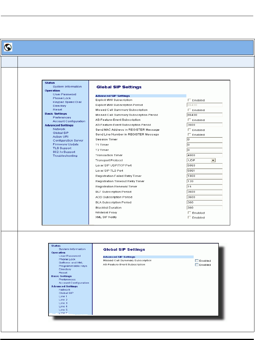
Global SIP Settings
41-001160-03, Rev 00, Releaes 2.4 4-87
Configuring Network and Session Initiation Protocol (SIP) Features
.
Aastra Web UI
Step Action
For Global configuration, click on Advanced Settings->Global SIP->Advanced SIP Settings.
1 Or for per-line configuration, click on Advanced Settings->Line N (1-9).
Draft 1

Global SIP Settings
4-88 41-001160-03, Rev 00, Releaes 2.4
IP Phone Administrator Guide
2 Enable the "Explicit MWI Subscription" field by checking the check box.
(Disable this field by unchecking the check box. Default is disabled).
If the IP phone has a message waiting subscription with the Service Provider, a Message Waiting
Indicator (MWI) (LED or display icon) tells the user there is a message on the IP Phone.
3 If you enable the “Explicit MWI Subscription” field, then in the “Explicit MWI Subscription Period”
field, enter the requested duration, in seconds, before the MWI subscription times out. The phone
re-subscribes to MWI before the subscription period ends. Default is 86400.
4 Enable the “Missed Call Summary Subscription” field by checking the check box.
(Disable this field by unchecking the check box. Default is disabled).
This feature allows missed calls that have been redirected by the server, to be incremented in the
missed calls indicator on the phone it was initially directed to.
For more information about this feature, see Chapter 6, the section, “Missed Call Summary
Subscription” on page 6-13.
Note: The “Missed Call Summary Subscription” feature is configurable on a global or per-line basis.
5 If you enable the “Missed Call Summary Subscription” field, then in the “Missed Call Summary
Subscription Period” field, enter the amount of time, in seconds, that the phone uses the Missed
Calls Summary Subscription feature. Default is 86400.
For more information about this feature, see Chapter 6, the section, “Missed Call Summary
Subscription” on page 6-13.
Note: The “Missed Call Summary Subscription Period” is configurable on a global basis only.
6 Enable the “AS-Feature-Event Subscription” field by checking the check box.
(Disable this field by unchecking the check box. Default is disabled).
This feature enables or disables the specified line with the BroadSoft’s server-side DND, CFWD, or
ACD features.
For more information about this feature, see Chapter 6, the section, “As-Feature-Event Subscription”
on page 6-17.
Note: The “AS-Feature-Event Subscription ” feature is configurable on a global or per-line basis.
Aastra Web UI
Step Action
Draft 1

Global SIP Settings
41-001160-03, Rev 00, Releaes 2.4 4-89
Configuring Network and Session Initiation Protocol (SIP) Features
7 If you enable the “AS-Feature-Event Subscription” field, then in the “AS-Feature-Event
Subscription Period” field, enter the amount of time, in seconds, between resubscribing. If the
phone does not resubscribe in the time specified for this parameter, it loses subscription. Default is
3600.
For more information about this feature, see Chapter 6, the section, “As-Feature-Event Subscription”
on page 6-17.
8 Enable the “Send MAC Address in REGISTER Message” and the “Send Line Number in
REGISTER Message” fields by checking the check boxes.
(Disable these fields by unchecking the check boxes. Default is disabled for both fields).
For more information about these message features, see Chapter 6, the section, “MAC Address/Line
Number in REGISTER Messages” on page 6-5.
Note: The “AS-Feature-Event Subscription Period” feature is configurable on a global basis only
9 In the "Session Timer" field, enter the time, in seconds, that the IP phone uses to send periodic
re-INVITE requests to keep a session alive. The proxy uses these re-INVITE requests to maintain the
status' of the connected sessions. See RFC4028 for details.
10 In the "Timer 1 and Timer 2" fields, enter a time, in milliseconds, that will apply to an IP phone
session. These timers are SIP transaction layer timers defined in RFC 3261.
Timer 1 is an estimate of the round-trip time (RTT). Default is 500 msec.
Timer 2 represents the amount of time a non-INVITE server transaction takes to respond to a
request. Default is 4 seconds.
11 In the "Transaction Timer" field, enter the amount of time, in milliseconds, that the phone allows the
call server (registrar/proxy) to respond to SIP messages that it sends.
Valid values are 4000 to 64000. Default is 4000.
Note: If the phone does not receive a response in the amount of time designated for this parameter,
the phone assumes the message has timed out.
12 In the "Transport Protocol" field, select a transport protocol to use when sending SIP Real-time
Transport Protocol (RTP) packets. Valid values are User Datagram Protocol (UDP) and Transmission
Control Protocol (TCP), UDP, TCP, Transport Layer Security (TLS) or Persistent TLS. The value
“UDP” is the default. For more information about TLS, see “RTP Encryption” on page 4-97 and
Chapter 6, the section, “Transport Layer Security (TLS)” on page 6-26.
Aastra Web UI
Step Action
Draft 1

Global SIP Settings
4-90 41-001160-03, Rev 00, Releaes 2.4
IP Phone Administrator Guide
13 In the "Local SIP UDP/TCP Port" field, specify the local source port (UDP/TCP) from which the
phone sends SIP messages. Default is 5060.
For more information about this feature, see the section, “SIP and TLS Source Ports for NAT
Traversal” on page 4-37.
14 In the "Local SIP TLS Port" field, specify the local source port (SIPS/TLS) from which the phone
sends SIP messages. Default is 5061.
For more information about this feature, see the section, “SIP and TLS Source Ports for NAT
Traversal” on page 4-37.
15 In the " Registration Failed Retry Timer" field, enter the amount of time, in seconds, that the phone
waits between registration attempts when a registration is rejected by the registrar.
Valid values are 30 to 1800. Default is 1800.
16 In the " Registration Timeout Retry Timer" field, enter the amount of time, in seconds, that the
phone waits until it re-attempts to register after a REGISTER message times out.
Valid values are 30 to 214748364. Default is 120.
17 In the " Registration Renewal Timer" field, enter the length of time, in seconds, prior to expiration,
that the phone renews registrations.
For example, if the value is set to 20, then 20 seconds before the registration is due to expire, a new
REGISTER message is sent to the registrar to renew the registration.
Valid values are 0 to 214748364. Default is 15.
18 The “BLF Subscription Period” field is enabled by default with a value of 3600 seconds.
This feature sets the time period, in seconds, that the IP phone resubscribes the BLF subscription
service after a software/firmware upgrade or after a reboot of the IP phone.
For information about setting the “BLF Subscription Period”, see Chapter 5, the section,
“BLF Subscription Period” on page 5-176.
19 (For Sylantro Servers) The “ACD Subscription Period” field is enabled by default with a value of
3600 seconds.
This feature sets the time period, in seconds, that the IP phone resubscribes the BLF subscription
service after a software/firmware upgrade or after a reboot of the IP phone.
For information about setting the “ACD Subscription Period”, see Chapter 5, the section,
“ACD Subscription Period” on page 5-198.
Aastra Web UI
Step Action
Draft 1

Global SIP Settings
41-001160-03, Rev 00, Releaes 2.4 4-91
Configuring Network and Session Initiation Protocol (SIP) Features
20 The “BLA Subscription Period” field is enabled by default with a value of 300 seconds.
This feature sets the amount of time, in seconds, that the phone waits to receive a BLA subscribe
message from the server. If you specify zero (0), the phone uses the value specified for the BLA
expiration in the subscribe message received from the server. If no value is specified, the phone uses
the default value of 300 seconds.
For information about setting the “BLA Subscription Period”, see Chapter 5, the section,
“BLA Subscription Period” on page 5-198.
21 (For Broadsoft Servers) The “Blacklist Duration” field is enabled by default with a value of 300
seconds (5 minutes). Valid values are 0 to 9999999.
This feature sets the time period, in seconds, that the IP phone resubscribes the BLF subscription
service after a software/firmware upgrade or after a reboot of the IP phone.
Note: The value of “0” disables the blacklist feature.
For information about setting the “Blacklist Duration”, see Chapter 6, the section, “Blacklist Duration”
on page 6-22.
22 Enable the "Whitelist Proxy" field by checking the check box.
(Disable this field by unchecking the check box. Default is disabled).
When this feature is enabled, an IP phone accepts call requests from a trusted proxy server only. The
IP phone rejects any call requests from an untrusted proxy server.
For information about setting the “Whitelist Proxy”, see Chapter 6, the section, “Whitelist Proxy” on
page 6-24.
Aastra Web UI
Step Action
Draft 1

Global SIP Settings
4-92 41-001160-03, Rev 00, Releaes 2.4
IP Phone Administrator Guide
23 Enable the "XML SIP Notify" field by checking the check box.
(Disable this field by unchecking the check box. Default is disabled).
Enabling this parameter allows the phone to accept or reject an aastra-xml SIP NOTIFY message.
Note: To ensure the SIP NOTIFY is coming from a trusted source, it is recommended that you enable
the Whitelist feature (Whitelist Proxy parameter) on the IP phone. If enabled, and the phone
receives a SIP NOTIFY from a server that is NOT on the whitelist (i.e. untrusted server), the phone
rejects the message.
For information about setting this feature, see Chapter 5, the section, “XML SIP Notify Events” on
page 5-339.
24 Click to save your changes.
Aastra Web UI
Step Action
Draft 1
Global SIP Settings
41-001160-03, Rev 00, Releaes 2.4 4-93
Configuring Network and Session Initiation Protocol (SIP) Features
Real-time Transport Protocol (RTP) Settings
Real-time Transport Protocol (RTP) is used as the bearer path for voice packets
sent over the IP network. Information in the RTP header tells the receiver how to
reconstruct the data and describes how the bit streams are packetized (i.e. which
codec is in use). Real-time Transport Control Protocol (RTCP) allows endpoints
to monitor packet delivery, detect and compensate for any packet loss in the
network. Session Initiation Protocol (SIP) and H.323 both use RTP and RTCP for
the media stream, with User Datagram Protocol (UDP) as the transport layer
encapsulation protocol.
You can set the following parameters for RTP on the IP Phones:
Note: If RFC2833 relay of DTMF tones is configured, it is sent on the
same port as the RTP voice packets. The phones support decoding and
playing out DTMF tones sent in SIP INFO requests. The following
DTMF tones are supported:
• Support signals 0-9, #, *
• Support durations up to 5 seconds
Aastra Web UI Parameters Configuration File Parameters
RTP Port sip rtp port
Basic Codecs (G.711 u-Law, G.711 a-Law, G.729) sip use basic codecs
Force RFC2833 Out-of-Band DTMF sip out-of-band dtmf
Customized Codec Preference List sip customized codec
DTMF Method (global and per-line settings) sip dtmf method (global and per-line settings)
RTP Encryption (global and per-line settings) sip srtp mode (global and per-line settings)
Silence Suppression sip silence suppression
Draft 1

Global SIP Settings
4-94 41-001160-03, Rev 00, Releaes 2.4
IP Phone Administrator Guide
RTP Port
RTP is described in RFC1889. The UDP port used for RTP streams is traditionally
an even-numbered port, and the RTCP control is on the next port up. A phone call
therefore uses one pair of ports for each media stream.
The RTP port is assigned to the first line on the phone, and is then incremented for
each subsequent line available within the phone to provided each line a unique
RTP port for its own use.
On the IP phone, the initial port used as the starting point for RTP/RTCP port
allocation can be configured using "RTP Port Base". The default RTP base port
on the IP phones is 3000.
For example, if the RTP base port value is 5000, the first voice patch sends RTP
on port 5000 and RTCP on port 5001. Additional calls would then use ports 5002,
5003, etc.
You can configure the RTP port on a global-basis only, using the configuration
files, the IP Phone UI, or the Aastra Web UI.
Basic Codecs (G.711 u-Law, G.711 a-Law, G.729)
CODEC is an acronym for COmpress-DECompress. It consists of a set of
instructions that together implement one or more algorithms. In the case of IP
telephony, these algorithms are used to compress the sampled speech data, to
decrease the content's file size and bit-rate (the amount of network bandwidth in
kilobits per second) required to transfer the audio. With smaller file sizes and
lower bit rates, the network equipment can store and stream digital media content
over a network more easily.
Aastra IP phones support the International Telecommunications Union (ITU)
transmission standards for the following CODECs:
•Waveform CODECs: G.711 pulse code modulation (PCM) with a-Law or
u-Law companding
•Parametric CODEC: G.729a conjugate structure - algebraic code excited
linear prediction (CS_ACELP).
Draft 1
Global SIP Settings
41-001160-03, Rev 00, Releaes 2.4 4-95
Configuring Network and Session Initiation Protocol (SIP) Features
All Codecs have a sampling rate of 8,000 samples per second, and operate and
operate in the 300 Hz to 3,700 Hz audio range. The following table lists the
default settings for bit rate, algorithm, packetization time, and silence suppression
for each Codec, based on a minimum packet size.
Default Codec Settings.
You can enable the IP phones to use a default "basic codec" set, which consists of
the set of codecs and packet sizes shown above.
Or you can instead configure a custom set of codecs and attributes instead of using
the defaults.
Customized Codec Preference List
You can also configure the IP phones to use preferred Codecs. To do this, you
must enter the payload value (payload), the packetization time in milliseconds
(ptime), and enable or disable silence suppression (silsupp).
Payload is the codec type to be used. This represents the data format carried
within the RTP packets to the end user at the destination. You can enter payload
values for G.711 a-law, G.711 u-law, and G.729a.
Ptime (packetization time) is a measurement of the duration of PCM data within
each RTP packet sent to the destination, and hence defines how much network
bandwidth is used for transfer of the RTP stream. You enter the ptime values for
the customized Codec list in milliseconds. (See table below).
CODEC Bit Rate Algorithm Packetizatio
n Time Silence
Suppression
G.711 a-law 64 Kb/s PCM 30 ms enabled
G.711 u-law 64 Kb/s PCM 30 ms enabled
G.729a 8
Kb/s CS-ACELP 30 ms enabled
Note: The basic and custom codec parameters apply to all calls, and are
configured on a global-basis only using the configuration files or the
Aastra Web UI.
Draft 1
Global SIP Settings
4-96 41-001160-03, Rev 00, Releaes 2.4
IP Phone Administrator Guide
Silsupp is used to enable or disable silence suppression. Voice Activity Detection
(VAD) on the IP phones is used to determine whether each individual packet
contains useful speech data. Enabling silsupp results in decreased network
bandwidth, by avoiding sending RTP packets for any frame where no voice
energy was detected by the VAD.
You must enter the values for this feature in list form as shown in the following
example:
payload=8;ptime=10;silsupp=on,payload=0;ptime=10;silsupp=off
The valid values for creating a Codec preference list are as follows.
Customized Codec Settings
You can specify a customized Codec preference list on a global-basis using the
configuration files or the Aastra Web UI.
Out-of-Band DTMF
The IP phones support out-of-band Dual-Tone Multifrequency (DTMF) mode
according to RFC2833. In the Aastra Web UI, you can enable or disable this
feature as required. The "out-of-band DTMF" is enabled by default.
In out-of-band mode, the DTMF audio is automatically clamped (muted) and
DTMF digits are not sent in the RTP packets.
You can configure out-of-band DTMF on a global-basis using the configuration
files or the Aastra Web UI.
Attribute Value
payload 0 for G.711 u-Law
8 for G.711 a-Law
18 for G.729a
ptime (in milliseconds) 5, 10, 15, 20.......90
silsupp on
off
Draft 1

Global SIP Settings
41-001160-03, Rev 00, Releaes 2.4 4-97
Configuring Network and Session Initiation Protocol (SIP) Features
DTMF Method
A feature on the IP phone allows you to select the DTMF method that the phone
uses to send DTMF digits from the IP phone via INFO messages. You can set the
DTMF method as Real-Time Transport Protocol (RTP), SIP info, or both.
You can configure the DTMF method on a global or per-line basis using the
configuration files or the Aastra Web UI.
RTP Encryption
The IP Phones include support for Secure Real-time Transfer Protocol (SRTP),
using Session Description Protocol Security (SDES) key negotiation, for
encryption and authentication of RTP/RTCP messages sent and received by the
Aastra IP phones on your network.
As administrator, you specify the global SRTP setting for all lines on the IP
phone. You can choose among three levels of SRTP encryption, as follows:
•SRTP Disabled (default): IP phone generates and receives nonsecured RTP
calls. If the IP phone gets called from SRTP enabled phone, it ignores SRTP
tries to answer the call using RTP. If the receiving phone has SRTP only
enabled, the call fails; however, if it has SRTP preferred enabled, it will accept
RTP call.
•SRTP Preferred: IP phone generates RTP secured calls, and accepts both
secured and non-secured RTP calls. If the receiving phone is not SRTP
enabled, it sends non-secured RTP calls instead.
•SRTP Only: IP phone generates and accepts RTP secured calls only; all other
calls are rejected (fail).
You can override the global setting as necessary, configuring SRTP support on a
per-line basis. This allows IP phone users to have both secured and unsecured
lines operating on the same phone.
Draft 1
Global SIP Settings
4-98 41-001160-03, Rev 00, Releaes 2.4
IP Phone Administrator Guide
If an SRTP enabled IP phone initiates a call, and the receiving phone is also SRTP
enabled, the IP Phone UI displays a “lock” icon, indicating that the call is secure.
If the receiving phone does not support SRTP, the IP phone will send unsecured
RTP messages instead of SRTP encrypted messages. However in this case, the IP
Phone UI does not display the lock icon - indicating a non-secure call.
You can configure SRTP on a global or per-line basis using the configuration files
or the Aastra Web UI.
Silence Suppression
In IP telephony, silence on a line (lack of voice) uses up bandwidth when sending
voice over a packet-switched system. Silence suppression is encoding that starts
and stops the times of silence in order to eliminate that wasted bandwidth.
Silence suppression is enabled by default on the IP phones. The phone negotiates
whether or not to use silence suppression. Disabling this feature forces the phone
to ignore any negotiated value.
You can configure silence suppression on a global-basis using the configuration
files or the Aastra Web UI.
Note: If you enable SRTP, then you should also enable Transport Layer
Security (TLS). This prevents capture of the key used for SRTP
encryption. To enable TLC, set the Transport Protocol parameter
(located on the Global SIP Settings menu) to TLS.
Draft 1
Global SIP Settings
41-001160-03, Rev 00, Releaes 2.4 4-99
Configuring Network and Session Initiation Protocol (SIP) Features
Configuring RTP Features
Use the following procedures to configure the RTP features on the IP phone.
Configuration Files
For specific parameters you can set for RTP features in the configuration files, see Appendix A, the section,
“RTP, Codec, DTMF Global Settings” on page A-114.
IP Phone UI
Step Action
1 Press on the phone to enter the Options List.
2Select Administrator Menu.
3 Enter your Administrator password.
Note: The IP Phones accept numeric passwords only.
4Select SIP Settings.
5Select RTP Port Base to change the RTP port base setting. Default is 3000.
6 Press Done (2 times) to save the change.
Note: The session prompts you to restart the IP phone to apply the configuration settings
7Select Restart.
Draft 1
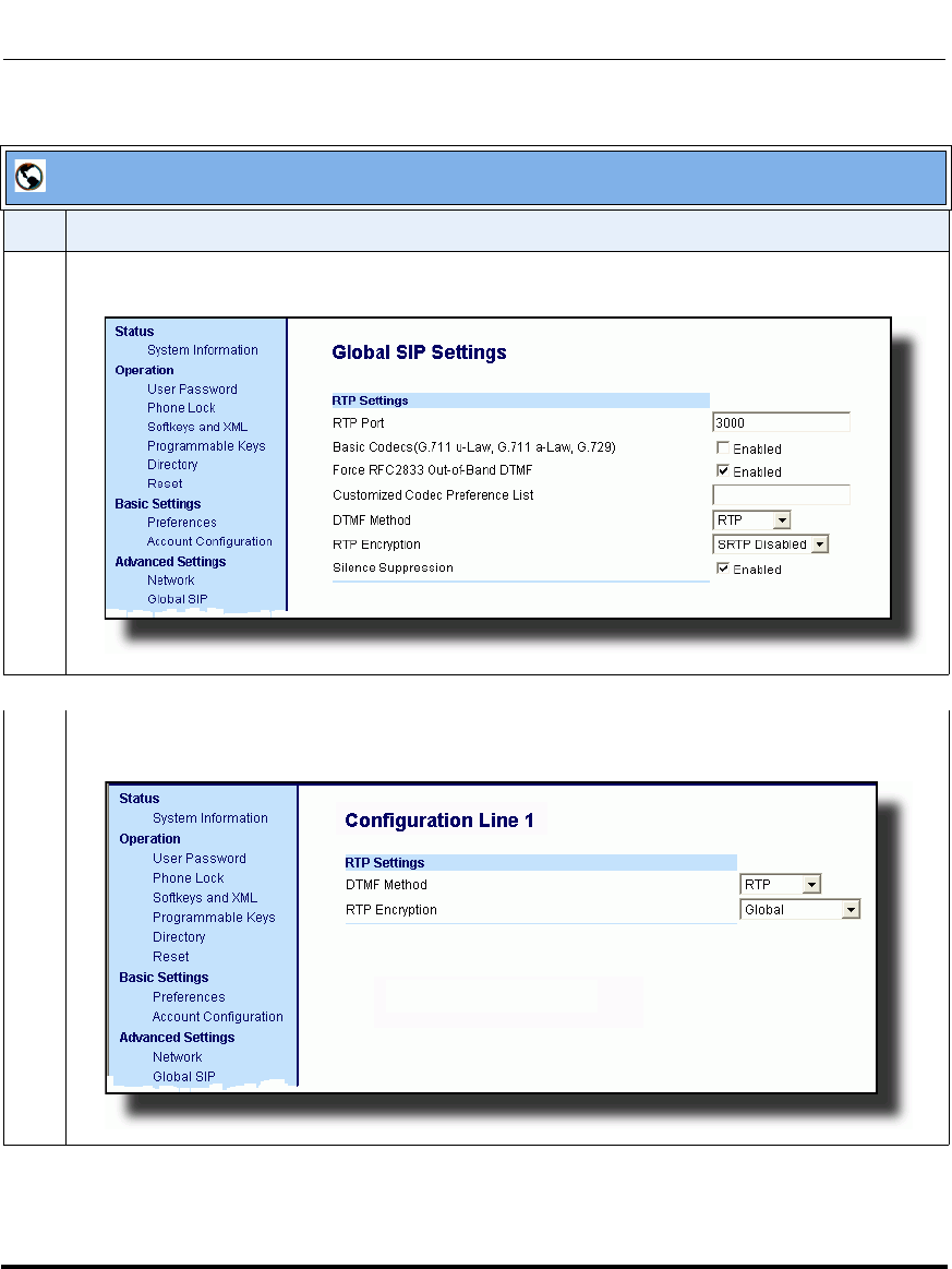
Global SIP Settings
4-100 41-001160-03, Rev 00, Releaes 2.4
IP Phone Administrator Guide
.
Aastra Web UI
Step Action
1 Click on Advanced Settings->Global SIP->RTP Settings.
Global Settings.
Click on Advanced Settings->Line <N>->RTP Settings.
Per-Line Settings.
Draft 1
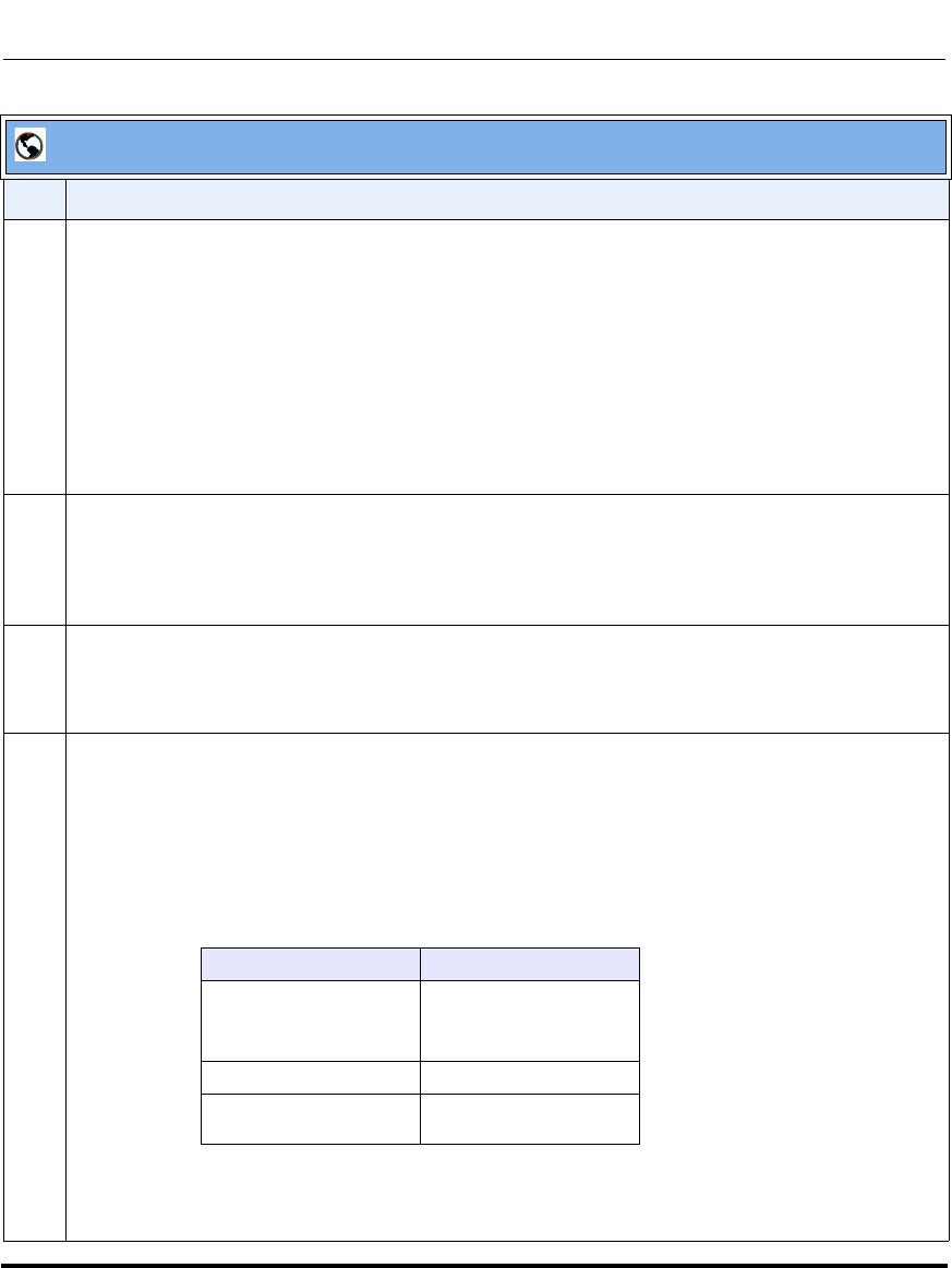
Global SIP Settings
41-001160-03, Rev 00, Releaes 2.4 4-101
Configuring Network and Session Initiation Protocol (SIP) Features
2 Enter an RTP Port Base in the RTP Port field. Default is 3000.
The RTP Port indicates the port through which the RTP packets are sent. This value must specify the
beginning of the RTP port range on the gateway or router. The RTP port is used for sending DTMF
tones and for the audio stream. Your network administrator may close some ports for security
reasons. You may want to use this parameter to send RTP data using a different port.
Note: The phones support decoding and playing out DTMF tones sent in SIP INFO requests. The
following DTMF tones are supported:
• Support signals 0-9, #, *
• Support durations up to 5 seconds
3 Enable the "Basic Codecs (G.711 u-Law, G.711 a-Law, G.729)" field by checking the check box.
(Disable this field by unchecking the box. Default is disabled).
Enabling this parameter allows the IP phone to use the basic Codecs when sending/receiving RTP
packets.
4The "Force RFC2833 Out-of-Band DTMF" field is enabled by default. Disable this field by
unchecking the box.
Enabling this parameter forces the IP phone to use out-of-band DTMF according to RFC2833.
5 Enter a "Customized Codec Preference List". For example,
payload=8;ptime=10;
silsupp=on,
payload=0;ptime=10;
silsupp=off
Valid values are:
For this parameter, you specify a customized codec list which allows you to use the preferred Codecs
for this IP phone. Default for the “Customized Codec Preference List” is blank.
Aastra Web UI
Step Action
Attribute Value
payload 0 for G.711 u-Law
8 for G.711 a-Law
18 for G.729a
ptime (in milliseconds) 5, 10, 15, 20.....90
silsupp on
off
Draft 1
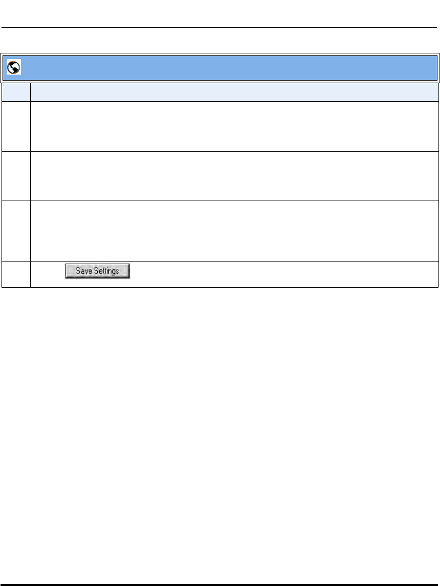
Global SIP Settings
4-102 41-001160-03, Rev 00, Releaes 2.4
IP Phone Administrator Guide
6 Select a method to use from the “DTMF Method” list box. Valid values are RTP, SIP Info, Both.
Default is RTP.
Note: You can configure the DTMF Method on a global or per-line basis.
7 Select the type of RTP encryption to use from the “RTP Encryption” list box. Valid values are SRTP
Disabled, SRTP Preferred, or SRTP Only. Default is SRTP Disabled.
Note: You can configure RTP Encryption on a global or per-line basis.
8The “Silence Suppression” field is enabled by default. Disable this field by unchecking the check
box.
When enabled, the phone negotiates whether or not to use silence suppression. Disabling this
feature forces the phone to ignore any negotiated value.
9 Click to save your changes.
Aastra Web UI
Step Action
Draft 1

Global SIP Settings
41-001160-03, Rev 00, Releaes 2.4 4-103
Configuring Network and Session Initiation Protocol (SIP) Features
Autodial Settings
The IP phones include a feature called “Autodial”. When you configure Autodial
on an IP phone, the phone automatically dials a preconfigured number whenever
it is off-hook. Depending on the configuration you specify, the Autodial functions
as either a “hotline”, or as a “warmline,” as follows:
•Hotline (default): The IP phone immediately dials a preconfigured number
when you lift the handset.
•Warmline: The IP phone waits for a specified amount of time after you lift
the handset before dialing a preconfigured number. If you do not dial a
number within the time allotted, then the IP phone begins to dial the number.
By default, the Autodial feature functions as a hotline. If you want Autodial to
function as a warmline, you can use the Autodial “time-out” parameter to specify
the length of time (in seconds) the IP phone waits before dialing a preconfigured
number.
As administrator, you configure Autodial globally, or on a per-line basis, for an IP
phone. The line setting overrides the global setting. For example, you can disable
Autodial on a specific line simply by setting the line’s autodial number parameter
to empty (blank).
Note: IMPORTANT INFORMATION before configuring Autodial on
your IP phone:
• Any speeddial numbers that you configure on an IP phone are not
affected by autodial settings.
• If you configure autodial on your IP phone, any lines that function as
hotlines do not accept conference calls, transferred calls, and/or
intercom calls.
Draft 1
Global SIP Settings
4-104 41-001160-03, Rev 00, Releaes 2.4
IP Phone Administrator Guide
Configuring AutoDial Using the Configuration Files
You use the following parameters to configure Autodial using the configuration
files:
Global Configuration
• sip autodial number
• sip autodial timeout
Per-Line Configuration
• sip lineN autodial number
• sip lineN autodial timeout
Configuration Files
For specific parameters you can set in the configuration files, see Appendix A, the section, “Autodial
Settings” on page A-119.
Draft 1
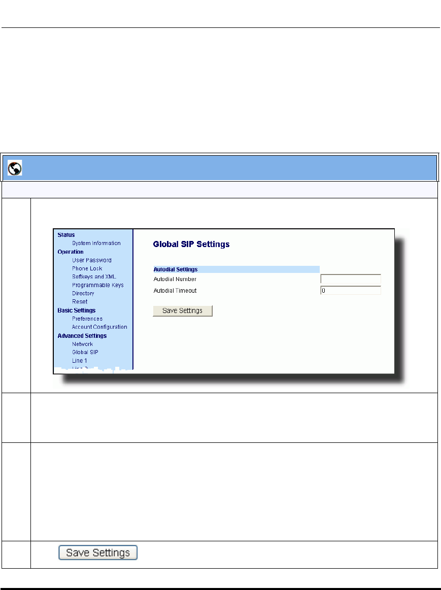
Global SIP Settings
41-001160-03, Rev 00, Releaes 2.4 4-105
Configuring Network and Session Initiation Protocol (SIP) Features
Configuring Autodial Using the Aastra Web UI
Use the following procedure to configure Autodial using the Aastra Web UI.
By default, your IP phone uses the global settings you specify for Autodial for all
lines on your IP phone. However, you can also configure Autodial on a per-line
basis.
Aastra Web UI
Global Configuration
1 Click on Advanced Settings->Global SIP->Autodial Settings.
2 In the “Autodial Number” field, specify the SIP number that the IP phone dials whenever the IP
phone is off-hook. An empty (blank) value disables autodial on the phone.
For example: 8500
3 In the “Autodial Timeout” field, specify a value, in seconds, for the timer as follows:
• If you want the IP phone to autodial the number immediately (hotline) whenever the IP phone is
off-hook, accept the default value of 0.
• If you want to specify a length of time for the IP phone to wait before dialing the number, enter
the length of time (in seconds). For example: 30
Valid values are 0 to 120.
4 Click to save your changes.
Draft 1
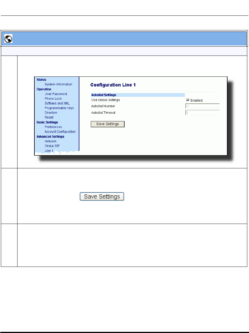
Global SIP Settings
4-106 41-001160-03, Rev 00, Releaes 2.4
IP Phone Administrator Guide
Per-Line Configuration
1 Click on Advanced Settings->Line <1 - 9>->Autodial Settings.
2 Do one of the following actions:
• To allow this line to use the global autodial settings, click on the Use Global Settings parameter
to enable it, then click to save your changes.
• To specify a different autodial configuration for this specific line, disable the Use Global
Settings parameter. Then proceed to step 3.
3 In the “Autodial Number” field, specify the SIP number for this line that the IP phone dials
whenever the IP phone is off-hook as follows:
• If set to -1, then the global autodial settings for this IP phone to this line.
• If set to empty (blank), then disable Autodial on this line.
• If set to a valid SIP number, dial the SIP number specified for this line. For example: 8500
Aastra Web UI
Draft 1
Global SIP Settings
41-001160-03, Rev 00, Releaes 2.4 4-107
Configuring Network and Session Initiation Protocol (SIP) Features
4 In the “Autodial Timeout” field, specify a value, in seconds, for the timer for this line as follows:
• If you want the IP phone to autodial the number immediately (hotline) whenever the IP phone is
off-hook, accept the default value of 0.
• If you want to specify a length of time for the IP phone to wait before dialing the number, enter
the length of time (in seconds). For example: 30
Valid values are 0 to 120.
5 Click to save your changes.
Aastra Web UI
Draft 1
Configuration Server Protocol
4-108 41-001160-03, Rev 00, Releaes 2.4
IP Phone Administrator Guide
Configuration Server Protocol
You can download new versions of firmware and configuration files from the
configuration server to the IP phone using any of the following types of protocols:
TFTP, FTP, HTTP, and HTTPS. For each Protocol, you can specify the path for
which the configuration files are located on the server. For HTTP and HTTPS,
you can also specify the port number to use for downloading the phone
configuration. For FTP, you can configure a Username and Password that are
authenticated by the FTP server.
The TFTP setting is the default download protocol. You can configure the type of
protocol that the IP phones use by setting it in the configuration files, the IP phone
UI, or the Aastra Web UI.
Configuring the Configuration Server Protocol
Use the following procedure to configure the configuration server protocol.
Note: For DHCP to automatically populate the IP address or domain
name for the TFTP, FTP, HTTP, or HTTPS server, your DHCP server
must support download protocol according to RFC2131 and RFC1541 for
Option 66. For more information, see this chapter, the section, “DHCP”
on page 4-4.
Configuration Files
For specific parameters you can set in the configuration files, see Appendix A, the section, “Configuration
Server Settings” on page A-18.
Draft 1
Configuration Server Protocol
41-001160-03, Rev 00, Releaes 2.4 4-109
Configuring Network and Session Initiation Protocol (SIP) Features
IP Phone UI
Step Action
1 Press on the phone to enter the Options List.
2Select Administrator Menu.
3 Enter your Administrator password.
Note: The IP Phones accept numeric passwords only.
4Select Configuration Server.
5Select Download Protocol.
6 Select from the following:
• Use TFTP
• Use FTP
• Use HTTP
• Use HTTPS
Default is “Use TFTP”.
The IP phone uses the protocol you select to download new firmware and configuration files from
the configuration server.
7Press Done (9480i, 9480i CT, 6755i, 6757i, 6757i CT) or Set (9143i, 6751i, 6753i) to save the
changes.
8 From the Configuration Server menu, select from the following. This selection is dependent on the
Download Protocol you selected in step 6.
TFTP Settings
FTP Settings
HTTP Settings
HTTPS Settings
Draft 1
Configuration Server Protocol
4-110 41-001160-03, Rev 00, Releaes 2.4
IP Phone Administrator Guide
9 Enter the IP address of the protocol server (in dotted decimal format).
Use the following table to configure the applicable server.
IP Phone UI
Step Action
TFTP Settings
-Select Primary TFTP
- Enter the IP address or fully qualified domain name of the primary TFTP server.
- Press Done or Set to save the change.
-Select Pri TFTP Path.
- Enter the path name for which the configuration files reside on the TFTP server for down-
loading to the IP Phone. If the IP phone’s files are located in a sub-directory beneath the
server’s root directory, the relative path to that sub-directory should be entered in this field.
Enter the path name in the form folderX\folderX\folderX. For example, ipphone\6757i\con-
figfiles.
Optional: You can also configure an Alternate TFTP server and Alternate TFTP Path if
required by selecting the “Alternate TFTP” and the “Alt TFTP Path” parameters.
- From the TFTP Settings menu, select Alternate TFTP and press Enter.
- Enter the IP address or fully qualified domain name of the alternate TFTP server.
- Press Done or Set to save the change.
-Select Alt TFTP Path.
- Enter the path name for which the configuration files reside on the Alternate TFTP server for
downloading to the IP Phone. If the IP phone’s files are located in a sub-directory beneath
the server’s root directory, the relative path to that sub-directory should be entered in this
field. Enter the path name in the form folderX\folderX\folderX. For example,
ipphone\6757i\configfiles.
FTP Settings
-Select FTP Server.
- Enter the IP address or fully qualified domain name of the FTP server.
- Press Done or Set to save the change.
-Select FTP Path.
- Enter the path name for which the configuration files reside on the FTP server for download-
ing to the IP Phone. If the IP phone’s files are located in a sub-directory beneath the server’s
root directory, the relative path to that sub-directory should be entered in this field. Enter the
path name in the form folderX\folderX\folderX. For example, ipphone\6757i\configfiles.
Optional: You can enter a username and password for accessing the FTP server if required:
-Select FTP Username.
- Enter a username for accessing the FTP server.
- Press Done.
-Select FTP Password.
- Enter a password for accessing the FTP server.
- Press Done or Set.
Draft 1
Configuration Server Protocol
41-001160-03, Rev 00, Releaes 2.4 4-111
Configuring Network and Session Initiation Protocol (SIP) Features
9
(Cont’d)
IP Phone UI
Step Action
HTTP Settings
-Select HTTP Server
- Enter the IP address of the HTTP server.
- Press Done or Set.
-Select HTTP Path.
- Enter the path name for which the configuration files reside on the HTTP server for down-
loading to the IP Phone. If the IP phone’s files are located in a sub-directory beneath the
server’s root directory, the relative path to that sub-directory should be entered in this field.
Enter the path name in the form folderX\folderX\folderX. For example, ipphone\6757i\con-
figfiles.
-Select HTTP Port.
- Enter the HTTP port that the server uses to load the configuration to the phone over HTTP.
Default is 80.
- Press Done or Set.
HTTPS Settings
-Select HTTP Client.
-Select Download Server.
- Enter the IP address of the HTTPS server.
- Press Done or Set.
-Select Download Path.
Enter the path name for which the configuration files reside on the HTTPS server for down-
loading to the IP Phone. If the IP phone’s files are located in a sub-directory beneath the
server’s root directory, the relative path to that sub-directory should be entered in this field.
Enter the path name in the form folderX\folderX\folderX. For example, ipphone\6757i\con-
figfiles.
- Press Done or Set.
-Select Client Method.
- Select the client method to use for downloading the configuration files (SSl 3.0 or TLS 1.0).
For more information about which client method to use, see the section, “HTTPS Client/
Server Configuration” on page 4-40.
-Select Download Port.
- Enter the HTTPS port that the server uses to load the configuration to the phone over
HTTPS. Default is 443.
Draft 1
Configuration Server Protocol
4-112 41-001160-03, Rev 00, Releaes 2.4
IP Phone Administrator Guide
9
(Cont’d)
Reference
For more information on configuring the HTTPS security method, HTTP to HTTPS redirect, and
HTTPS server blocking for HTTP XML POSTs, see the section, “HTTPS Client/Server
Configuration” on page 4-40.
10 Press Done or Set repeatedly until the session prompts you to restart the IP phone to apply the
configuration settings.
11 Select Restart.
IP Phone UI
Step Action
HTTPS Settings (Continued)
-Select HTTPS Server.
-Select HTTP->HTTPS.
- For 9143i, 6751i, 6753i:
Press Change to select “Do not redirect”or “Redirect”. Default is “Do not redirect”.
Enabling this feature redirects the HTTP protocol to HTTPS.
Press Set.
- For 9480i, 9480i CT, 6755i, 6757i, 6757i CT:
Press Change to select “Yes” and redirect HTTP to HTTPS. Select “No” to not direct HTTPS
to HTTPS, Default is “No”. Enabling this feature redirects the HTTP protocol to HTTPS.
Press Done.
-Select XML HTTP POSTs.
- For 9143i, 6751i, 6753i:
Press Change to select “Do not block” or “Block”.
Enabling this feature blocks XML HTTP POSTs from the IP Phone.
- For 9480i, 9480i CT, 6755i, 6757i, 6757i CT:
Press Change to select “Yes” and block XML HTTP Posts. Select “No” to unblock XML
HTTP Posts. Default is “No”. Enabling this feature blocks XML HTTP POSTs from the IP
Phone.
Draft 1
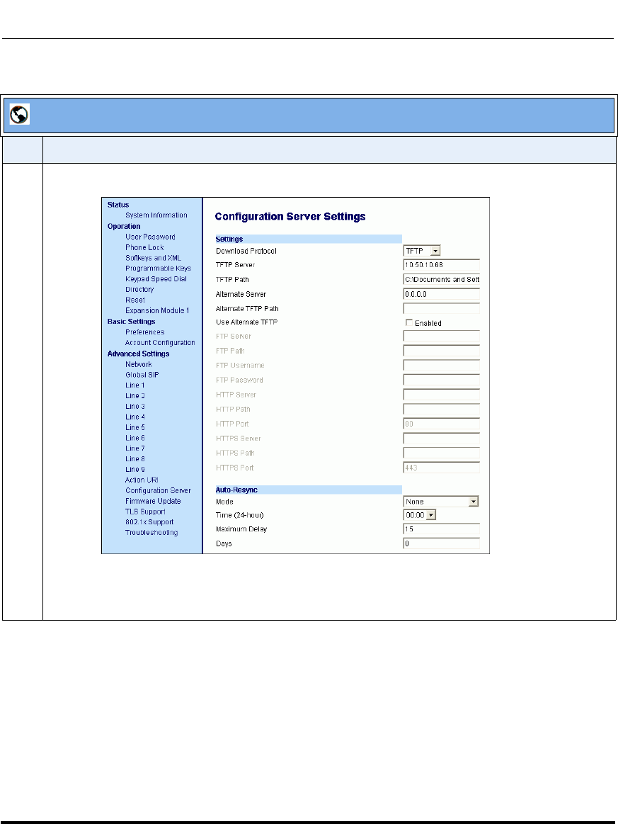
Configuration Server Protocol
41-001160-03, Rev 00, Releaes 2.4 4-113
Configuring Network and Session Initiation Protocol (SIP) Features
Aastra Web UI
Step Action
1 Click on Advanced Settings->Configuration Server.
Draft 1
Configuration Server Protocol
4-114 41-001160-03, Rev 00, Releaes 2.4
IP Phone Administrator Guide
2 Select the protocol from the "Download Protocol" list box. Valid values are TFTP, FTP, HTTP, and
HTTPS. Default is TFTP.
The IP phone uses the protocol you select to download new firmware and configuration files from the
configuration server. Use the following table to configure the applicable server.
Aastra Web UI
Step Action
TFTP
- Enter an IP address or fully qualified domain name in the "TFTP Server" field.
- Enter the path name in the “TFTP Path” field for which the configuration files reside on the
TFTP server for downloading to the IP Phone. If the IP phone’s files are located in a
sub-directory beneath the server’s root directory, the relative path to that sub-directory
should be entered in this field. Enter the path name in the form folderX\folderX\folderX. For
example, ipphone\6757i\configfiles.
Optional: You can also configure an alternate TFTP server if required. If "Use Alternate
TFTP" is enabled, you must also enter an IP address or qualified domain name for the
alternate server in the "Alternate TFTP" field. You can also enter a path name for the alter-
nate TFTP server in the “Alternate TFTP Path” field.
FTP
- Enter an IP address or fully qualified domain name in the "FTP Server" fiel.d.
- Enter the path name in the “FTP Path” field for which the configuration files reside on the
FTP server for downloading to the IP Phone. If the IP phone’s files are located in a
sub-directory beneath the server’s root directory, the relative path to that sub-directory
should be entered in this field. Enter the path name in the form folderX\folderX\folderX. For
example, ipphone\6757i\configfiles.
Optional: You can enter a username and password for accessing the FTP server if
required.
- Enter a username for a user that will access the FTP server in the "FTP User Name" field.
- Enter a password for a user that allows access to the FTP server in the "FTP Password"
field.
Draft 1
Configuration Server Protocol
41-001160-03, Rev 00, Releaes 2.4 4-115
Configuring Network and Session Initiation Protocol (SIP) Features
3
Reference: For more information on configuring the HTTPS security method, HTTP to HTTPS
redirect, and HTTPS server blocking for HTTP XML POSTs, see the section, “HTTPS Client/Server
Configuration” on page 4-40.
4 Click to save your settings.
Note: The session prompts you to restart the IP phone to apply the configuration settings.
5Select Operation->Reset and click .
Aastra Web UI
Step Action
HTTP
- Enter an IP address or fully qualified domain name in the "HTTP Server" field.
- Enter the path name in the “HTTP Path” field for which the configuration files reside on the
HTTP server for downloading to the IP Phone. If the IP phone’s files are located in a
sub-directory beneath the server’s root directory, the relative path to that sub-directory
should be entered in this field. Enter the path name in the form folderX\folderX\folderX. For
example, ipphone\6757i\configfiles.
- Enter the HTTP port number in the “HTTP Port” field that the server uses to load the con-
figuration to the phone over HTTP.
Optional: You can enter a list of users to be authenticated when they access the HTTP
server in the "XML Push Server List (Approved IP Addresses)" field.
HTTPS
- Enter an IP address or fully qualified domain name in the "HTTPS Server" field.
- Enter the path name in the “HTTPS Path” field for which the configuration files reside on the
HTTP server for downloading to the IP Phone. If the IP phone’s files are located in a
sub-directory beneath the server’s root directory, the relative path to that sub-directory
should be entered in this field. Enter the path name in the form folderX\folderX\folderX. For
example, ipphone\6757i\configfiles.
- Enter the HTTPS port number in the “HTTPS Port” field that the server uses to load the
configuration to the phone over HTTPS.
Optional: You can enter a list of users to be authenticated when they access the HTTP
server in the "XML Push Server List (Approved IP Addresses)" field.
Draft 1

Configuration Server Protocol
4-116 41-001160-03, Rev 00, Releaes 2.4
IP Phone Administrator Guide
Draft 1
41-001160-03, Rev 00, Releaes 2.4 5-1
Chapter 5
Configuring Operational Features
About this chapter
Introduction
The IP phones have specific operational features you can configure to customize
your IP phone. This chapter describes each feature and provides procedures for
configuring your phone to use these features.
Topics
This chapter covers the following topics:
Topic Page
Operational Features page 5-5
User Passwords page 5-5
Administrator Passwords page 5-9
Locking/Unlocking the Phone page 5-10
Defining an Emergency Dial Plan page 5-16
Time and Date page 5-19
Time Zone & DST page 5-20
Time Servers page 5-27
Backlight Mode (9480i, 9480i CT, 6755i, 6757i, and 6757i CT only) page 5-30
Live Dial Pad* page 5-33
Language page 5-34
Locking IP Phone Keys page 5-49
Draft 1

About this chapter
5-2 41-001160-03, Rev 00, Releaes 2.4
IP Phone Administrator Guide
Locking/Unlocking the SAVE and DELETE keys (6753i) page 5-50
Local Dial Plan page 5-53
Park Calls/Pick Up Parked Calls page 5-59
Suppressing DTMF Playback page 5-63
Display DTMF Digits page 5-65
Call Waiting/Call Waiting Tone page 5-67
Stuttered Dial Tone page 5-70
XML Beep Support page 5-72
Status Scroll Delay page 5-74
Incoming Call Interrupts Dialing page 5-76
Switch Focus to Ringing Line page 5-79
Preferred Line and Preferred Line Timeout page 5-81
Goodbye Key Cancels Incoming Call page 5-85
UPnP Mapping Lines (for remote phones) page 5-87
Message Waiting Indicator Line page 5-89
DND Key Mode page 5-91
Call Forward Mode page 5-93
Link Layer Discovery Protocol for Media Endpoint Devices
(LLDP-MED) and Emergency Location Identification Number (ELIN) page 5-97
Incoming/Outgoing Intercom with Auto-Answer and Barge In page 5-102
Group Paging RTP Settings page 5-107
Key Mapping page 5-113
Ring Tones and Tone Sets page 5-117
Priority Alerting page 5-122
Directed Call Pickup (BLF or XML Call Interception) page 5-129
Softkeys/Programmable Keys/Feature Keys/Expansion Module Keys page 5-141
Customizing the Key Type List in the Aastra Web UI page 5-164
Speeddial Prefixes page 5-167
Enabling/Disabling Ability to Add or Edit a Speeddial Key page 5-168
Busy Lamp Field (BLF) page 5-169
BLF Subscription Period page 5-176
Topic Page
Draft 1

About this chapter
41-001160-03, Rev 00, Releaes 2.4 5-3
Configuring Operational Features
BLF/Xfer and Speeddial/Xfer Keys page 5-178
Speeddial/Conference Key (not applicable to the 6751i) page 5-184
Automatic Call Distribution (ACD) (for Sylantro Servers) page 5-188
ACD Subscription Period page 5-198
BLA Subscription Period page 5-200
Directed Call Pickup/Group Call Pickup (for Sylantro Servers) page 5-202
Do Not Disturb (DND) page 5-211
Bridged Line Appearance (BLA) page 5-222
BLA Support for Third Party Registration page 5-229
P-Preferred Identity Header for BLA Accounts page 5-230
BLA Support for Message Waiting Indicator (MWI) page 5-231
Park/Pick Up Key page 5-234
Last Call Return (lcr) (Sylantro Servers) page 5-245
Call Forwarding page 5-249
Callers List page 5-288
Customizable Callers List and Services Keys page 5-294
Missed Calls Indicator page 5-295
Directory List page 5-297
Voicemail (9480i, 9480i CT, 6755i, 6757i, and 6757i CT only) page 5-308
XML Customized Services page 5-311
Creating Customized XML Services on the IP Phones page 5-311
Configuring the Phone to use XML page 5-317
XML Get Timeout page 5-317
Configuring for XML on the IP Phone page 5-318
Using the XML Customized Service page 5-323
XML Action URIs page 5-325
Polling Action URIs page 5-334
Action URI Disconnected page 5-336
XML SIP Notify Events page 5-339
XML Softkey URI page 5-345
Web Applications Keys page 5-351
Topic Page
Draft 1
About this chapter
5-4 41-001160-03, Rev 00, Releaes 2.4
IP Phone Administrator Guide
XML Key Redirection page 5-352
Options Key Redirection (for Options Menu on all phones and
Services Menu on 6751i) page 5-353
XML Applications and Off-Hook Interaction page 5-355
XML URI for Key Press Simulation page 5-355
XML Override for a Locked Phone page 5-356
Audio Transmit and Receive Gain Adjustments page 5-357
Centralized Conferencing (for Sylantro and Broadsoft Servers) page 5-359
“SIP Join” Feature for 3-Way Conference (not applicable to the 6751i) page 5-363
Authentication Support for HTTP/HTTPS Download Methods, used
with Broadsoft Client Management System (CMS) page 5-365
Customizing the Display Columns on the M675i Expansion Module page 5-368
Topic Page
Draft 1
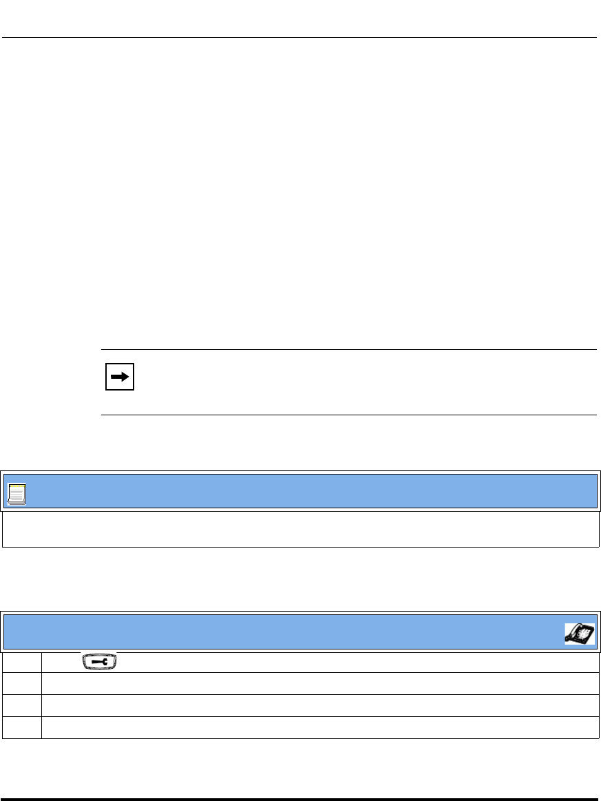
Operational Features
41-001160-03, Rev 00, Releaes 2.4 5-5
Configuring Operational Features
Operational Features
Description
This section describes the operational features managed and configured by a
System Administrator.
User Passwords
A user or an administrator can change the user passwords on the phone using the
configuration files, the IP phone UI, or the Aastra Web UI.
Use the following procedures to change the user password.
Configuring a User Password
Note: The IP phones support numeric characters only in passwords. If
you enter a password with alpha characters, the phone uses the default
password instead.
Configuration Files
For specific parameters you can set in the configuration files, see Appendix A, the section, “Password
Settings” on page A-15.
IP Phone UI
1 Press on the phone to enter the Options List.
2Select User Password.
3 Enter the current user password.
4 Press Enter.
Draft 1
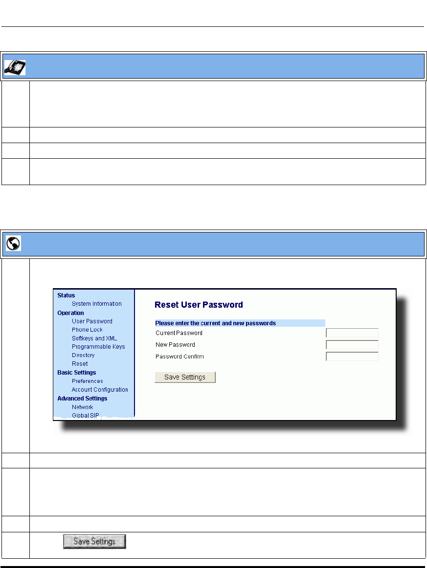
Operational Features
5-6 41-001160-03, Rev 00, Releaes 2.4
IP Phone Administrator Guide
5 Enter the new user password.
Note: The IP phones support numeric characters only in passwords. If you enter a password with
alpha characters, the phone uses the default password instead.
6 Press Enter.
7 Re-enter the new user password.
8 Press Enter.
A message, "Password Changed" displays on the screen.
Aastra Web UI
1 Click on Operation->User Password.
2 In the "Current Password" field, enter the current user password.
3 In the "New Password" field, enter the new user password.
Note: The IP phones support numeric characters only in passwords. If you enter a password with
alpha characters, the phone uses the default password instead.
4 In the "Password Confirm" field, enter the new user password again.
5 Click to save your changes.
IP Phone UI
Draft 1
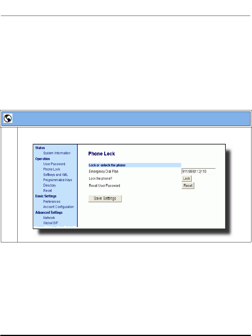
Operational Features
41-001160-03, Rev 00, Releaes 2.4 5-7
Configuring Operational Features
Resetting a User Password
If a user forgets his password, either the user or an administrator can reset it so a
new password can be entered. The reset user password feature resets the password
to the factory default which is blank (no password).
You can reset a user password using the Aastra Web UI only at the path
Operation->Phone Lock. Use the following procedure to reset a user password.
Aastra Web UI
1 Click on Operation->Phone Lock.
Draft 1
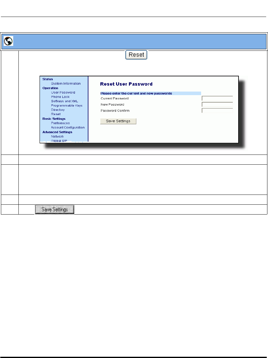
Operational Features
5-8 41-001160-03, Rev 00, Releaes 2.4
IP Phone Administrator Guide
2 In the “Reset User Password” field, click .
The following screen displays:
3 In the “Current Password” field, leave this blank.
4 In the “New Password” field, enter a new password for the user.
Note: The IP phones support numeric characters only in passwords. If you enter a password with
alpha characters, the phone uses the default password instead.
5 In the “Password Confirm” field, re-enter the new user password.
6 Click to save the new user password and perform the next procedure.
Aastra Web UI
Draft 1
Operational Features
41-001160-03, Rev 00, Releaes 2.4 5-9
Configuring Operational Features
Administrator Passwords
An administrator can change the administrator passwords on the phone using the
configuration files only.
An administrator can also assign a password for using the Options key on the IP
phone. You turn this feature on and off by entering the "options password
enabled" parameter followed by a valid value in the configuration files. Valid
values are 0 (false; Options key not password protected), or 1 (true; Options key
password protected). If this parameter is set to 1, a user has to enter a password at
the IP phone UI. If the password is entered correctly, the user is allowed to gain
access to the Options Menu and no more password prompts display for other
password protected screens. If the user fails to enter the correct password in three
attempts, access to the Options Menu is denied and the IP phone returns to the idle
screen.
Procedure
Use the following procedure to change the administrator password.
Configuration Files
For specific parameters you can set in the configuration files, see Appendix A, the section, “Password
Settings” on page A-15.
Draft 1
Operational Features
5-10 41-001160-03, Rev 00, Releaes 2.4
IP Phone Administrator Guide
Locking/Unlocking the Phone
A user or administrator can lock a phone to prevent it from being used or
configured. Once the phone is locked, the user or administrator can enter their
password to unlock the phone.
You can lock/unlock a phone using the configuration files, the IP Phone UI, or the
Aastra Web UI.
You can use any of the following methods to lock/unlock a phone:
• Using the IP Phone UI via the “Phone Lock” option in the Options Menu.
• Using the Aastra Web UI via the path Operation->Phone Lock.
• Using the configuration files to configure a key as “phonelock”, and then
pressing the key to lock/unlock the phone.
• Using the Aastra Web UI to configure a key as “Phone Lock”, and then
pressing the key to lock/unlock the phone.
Note: All of the methods above configure locking/unlocking of the
phone dynamically. Once configured, the feature takes affect
immediately. To unlock the phone, a user or administrator must enter their
password.
Draft 1
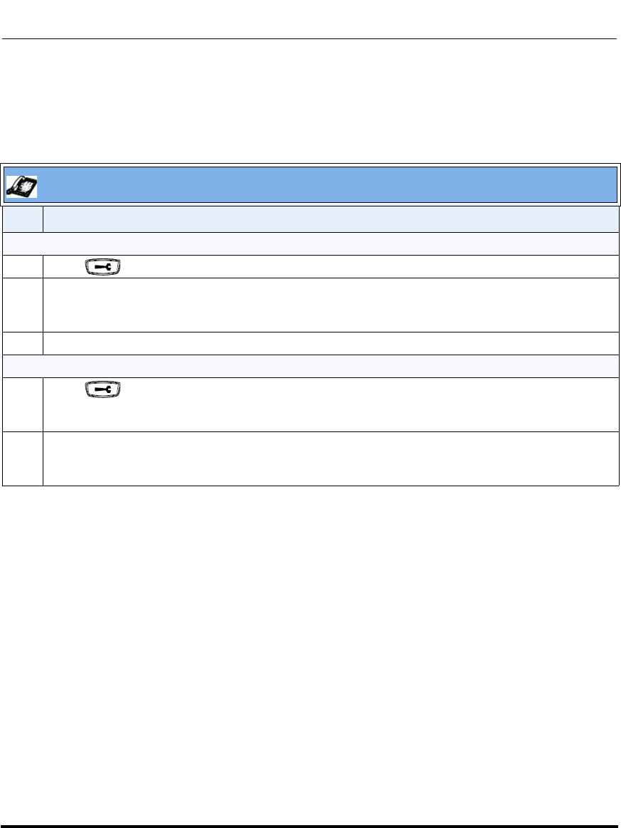
Operational Features
41-001160-03, Rev 00, Releaes 2.4 5-11
Configuring Operational Features
Locking/Unlocking the Phone Using the IP Phone UI
Use the following IP Phone UI procedure to lock/unlock an IP phone and prevent
it from being used or configured.
IP Phone UI
Step Action
Lock the phone:
1 Press on the phone to enter the Options List.
2Select Phone Lock.
The prompt, “Lock the phone?” displays.
3Press Lock to lock the phone.
Unlock the phone:
1 Press on the phone to enter the Options List.
The prompt, “To unlock the phone...Password:”
2 Enter the user or administrator password and press Enter.
The phone unlocks.
Draft 1
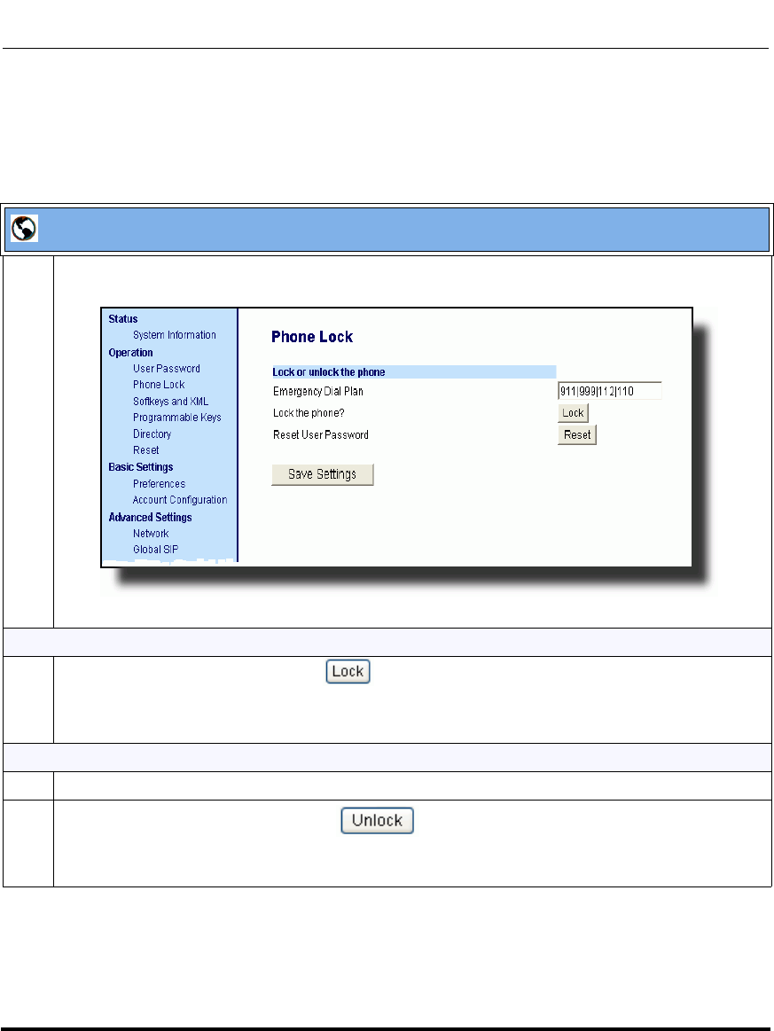
Operational Features
5-12 41-001160-03, Rev 00, Releaes 2.4
IP Phone Administrator Guide
Locking/Unlocking the Phone Using the Aastra Web UI
Use the following Aastra Web UI procedure to lock/unlock an IP phone and
prevent it from being used or configured.
Aastra Web UI
1 Click on Operation->Phone Lock.
Lock the phone:
2 In the “Lock the Phone?” field, click .
The phone locks dynamically and displays the following message:
“Phone is locked”.
Unlock the phone:
3 Click on Operation->Phone Lock.
4 In the “Unlock the Phone?” field, click .
The phone unlocks dynamically and displays the following message:
“Phone is unlocked”.
Draft 1
Operational Features
41-001160-03, Rev 00, Releaes 2.4 5-13
Configuring Operational Features
Configuring a Lock/Unlock Key Using the Configuration Files
Using the configuration files, you can configure a key on the phone (softkey,
programmable key, or expansion module key) to use as a lock/unlock key. In the
configuration files, you assign the function of the key as “phonelock”.
Use the following procedure to configure a key as a lock/unlock key using
the configuration files.
Reference
To use the lock/unlock softkey or programmable key, see “Using the Configured
Lock/Unlock Key on the IP Phone” on page 5-15.
Configuration Files
To configure a softkey/programmable key as a lock/unlock key using the configuration files, see Appendix A,
the section, “Softkey/Programmable Key/Feature Key/Expansion Module Key Parameters” on page A-192.
Draft 1
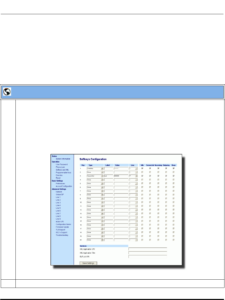
Operational Features
5-14 41-001160-03, Rev 00, Releaes 2.4
IP Phone Administrator Guide
Configuring a Lock/Unlock Key using the Aastra Web UI
Using the Aastra Web UI, you can configure a key on the phone (softkey,
programmable key, expansion module key) to use as a lock/unlock key. In the
Aastra Web UI, you assign the function of the as “Phone Lock”.
Use the following procedure to configure a key as a lock/unlock key using the
Aastra Web UI.
Aastra Web UI
1 Click on Operation->Softkeys and XML
or
Click on Operation->Programmable Keys
or
Click on Operation->Expansion Module <N>.
Note: Depending on your phone-model, the key configuration screen displays. The 6757i Key
Screen is shown as an example.
2 Select a key you want to configure for locking/unlocking the phone.
Draft 1
Operational Features
41-001160-03, Rev 00, Releaes 2.4 5-15
Configuring Operational Features
Using the Configured Lock/Unlock Key on the IP Phone
After configuring a key as a lock/unlock key, refer to the following procedure to
use the key on the IP phone.
3 In the “Type” field, select Phone Lock from the list of options.
4 Click to save your changes.
IP Phone UI
Step Action
Lock the phone:
1 Press the LOCK softkey.
The phone locks.
The LED for the softkey AND the Message Waiting Lamp illuminate steady ON.
An “Unlock” label appears next to the softkey you just pressed.
Unlock the phone:
1 Press the UNLOCK softkey.
A password prompt displays.
2 Enter the user or administrator password and press ENTER.
The phone unlocks.
The LED for the softkey AND the Message Waiting Lamp go OFF.
The “Lock” label appears next to the softkey you just pressed.
Aastra Web UI
Draft 1
Operational Features
5-16 41-001160-03, Rev 00, Releaes 2.4
IP Phone Administrator Guide
Defining an Emergency Dial Plan
Public telephone networks in countries around the world have a single emergency
telephone number (emergency services number), that allows a caller to contact
local emergency services for assistance when required. The emergency telephone
number may differ from country to country. It is typically a three-digit number so
that it can be easily remembered and dialed quickly. Some countries have a
different emergency number for each of the different emergency services.
You can specify the digits to dial on the IP phone for contacting emergency
services. Once you specify the emergency number(s) on the phone, you can dial
those numbers directly on the dial pad when required and the phone automatically
dials to those emergency services.
The following table describes the default emergency numbers on the IP phones.
Note: Contact your local phone service provider for available emergency
numbers in your area.
Emergency Number Description
911 A United States emergency number
999 A United Kingdom emergency number
112 An international emergency telephone
number for GSM mobile phone networks.
In all European Union countries it is also the
emergency telephone number for both
mobile and fixed-line telephones.
110 A police and/or fire emergency number in
Asia, Europe, Middle East, and South
America.
Draft 1

Operational Features
41-001160-03, Rev 00, Releaes 2.4 5-17
Configuring Operational Features
Emergency Dial Plan and Pattern Matching
The IP Phones support emergency dialing using pattern matching and prepend
dial plan functionality.
There are two ways to dial a number on the phone:
• dialing digit-by-digit (i.e., select line and dial)
• dialing by string (i.e., pre-dial then go off-hook)
When a user dials digit-by-digit, the phone adds every digit to a dialed string and
checks against the dial plan. If the phone is not locked, it checks against the
regular dial plan. If the phone is locked, it checks against the emergency dial plan.
When a user dials by string, (pre-dial, speed-dial, etc., and then goes off-hook),
and the phone is not locked, it checks to see if the number matches the emergency
dial plan. If it doesn’t match, it blocks the call from going through. If the phone is
locked, and the number matches the emergency dial plan it allows the call to go
through.
Adding a pre-pend to a dial plan also works with both dialing digit-by-digit and
dialing by string.
Limitation
The following is a limitation for emergency dial plans with pattern matching:
• Secondary dial tone is not supported.
You can set the emergency dial plan via the configuration files or the Aastra Web
UI.
Configuring an Emergency Dial Plan
Use the following procedures to specify the numbers to use on your phone for
dialing emergency services in your area.
Configuration Files
For specific parameters you can set in the configuration files, see Appendix A, the section, “Emergency Dial
Plan Settings” on page A-16.
Draft 1
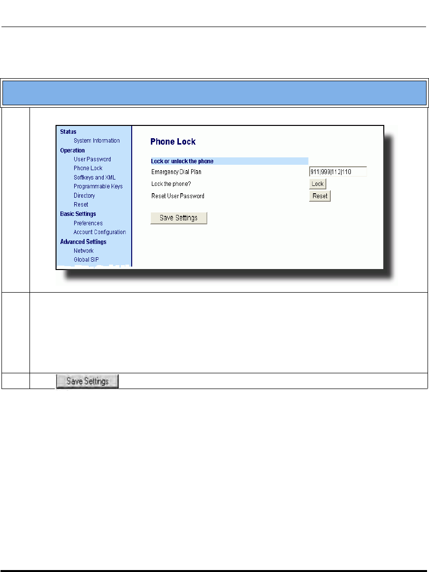
Operational Features
5-18 41-001160-03, Rev 00, Releaes 2.4
IP Phone Administrator Guide
Aastra Web UI
1 Click on Operation->Phone Lock.
2 In the “Emergency Dial Plan” field, enter the number used in your local area to contact emergency
services. For multiple numbers, enter a “|” between each emergency number.
For example:
911|110.
Default for this field is "x+#|xx+*". You can enter up to 512 characters in this field.
3 Click to save the emergency dial plan to your phone.
Draft 1
Operational Features
41-001160-03, Rev 00, Releaes 2.4 5-19
Configuring Operational Features
Time and Date
In addition to enabling/disabling the time server, you can also set the time and
date, set the time and date format, set the time zone, and set daylight savings time
on the IP phones. You configure these features using the configuration files, the IP
Phone UI, or the Aastra Web UI. The following table identifies which method of
configuration applies to each feature.
Daylight Savings Time (DST) Information
The Aastra IP Phones incorporate the federally mandated DST observance
change. This change became affective starting in 2007.
The US has made a change to its daylight savings time observance starting in
2007. The Energy Policy Act of 2005 mandates that DST will now begin at 2:00
A.M. on the second Sunday in March and revert to Standard time on the first
Sunday in November.
The changes to daylight savings time applies to the U.S. and Canada, but may
impact other countries outside North America.
Feature Method of configuration
Set Time IP Phone UI
Set Time Format Configuration Files
IP Phone UI
Aastra Web UI
Set Date IP Phone UI
Set Date Format Configuration Files
IP Phone UI
Aastra Web UI
Set Time Zone IP Phone UI
Configuration Files
Set Daylight Savings Time IP Phone UI
Configuration Files
Note: In previous years, the DST began on the first Sunday of April and
ended on the first Sunday of October.
Draft 1

Operational Features
5-20 41-001160-03, Rev 00, Releaes 2.4
IP Phone Administrator Guide
Time Zone & DST
There are two ways you can set the time zone on the IP Phones.
First Method - You can set a time zone using the Time Zone option in the IP
Phone UI or you can use the “time zone name” parameter in the configuration
files. Both methods allow you to enter a value from the Time Zone table. The list
of time zone names is provided in the table in Appendix A, the section, “Time
Zone Name/Time Zone Code Table” on page A-47. The following is an example:
time zone name: US-Eastern
Second Method - You can use the “time zone name” parameter in the
configuration files, and specify a value of “custom” for this parameter. This
method allows you to customize the time zone for your area using additional
configuration parameters. The following is an example using relative time for
EST:
time zone name: custom
The following table identifies the additional parameters you can enter in the
configuration files if you want to customize your time zone.
Custom Configuration
File Parameter Description Example
time zone minutes The number of minutes the time zone is
offset from UTC (Coordinated Universal
Time). This can be positive (West of the
Prime Meridian) or negative (East of the
Prim Meridian). Eastern Standard Time
(EST) has a value of 300.
custom time zone minutes: 300
dst minutes The number of minutes to add during
Daylight Saving Time. Valid values are a
positive integer between 0 to 60.
dst minutes: 60
dst [start|end] relative date Specifies how to interpret the start and
end day, month, and week parameters -
absolute (0) or relative (1).
dst [start|end] relative date: 1
Draft 1

Operational Features
41-001160-03, Rev 00, Releaes 2.4 5-21
Configuring Operational Features
Absolute Time (not applicable to Eastern Standard Time (EST))
dst start month The month that DST starts. Valid values
are 1 to 12 (January to December). dst start month: 3
dst end month The month that DST ends. Valid values
are 1 to 12 (January to December). dst end month: 4
dst [start |end] week Not applicable to absolute time. N/A
dst start day The day of the month that DST starts.
Valid values are 1 to 31. dst start day: 15
dst end day The day of the month that DST ends.
Valid values are 1 to 31. dst end day: 31
dst start hour The hour that DST starts. Valid values
are an integer from 0 (midnight) to 23. dst start hour: 5
dst end hour The hour that DST ends. Valid values
are an integer from 0 (midnight) to 23. dst end hour: 23
Relative Time
dst start month The month that DST starts. Valid values
are 1 to 12 (January to December). dst start month: 4
dst end month The month that DST ends. Valid values
are 1 to 12 (January to December). dst end month: 5
dst start week The week in the specified month in
which DST starts. Valid value is a
positive or negative integer from 1 to 5.
1 = first full week of month
-1 = last full week of month
2 = second full week of month
.
.
.
-5 -= fifth full week of month
dst start week: 2
Custom Configuration
File Parameter Description Example
Draft 1

Operational Features
5-22 41-001160-03, Rev 00, Releaes 2.4
IP Phone Administrator Guide
dst end week The week in the specified month in
which DST ends. Valid value is a
positive or negative integer from 1 to 5.
1 = first full week of month
-1 = last full week of month
2 = second full week of month
.
.
.
-5 -= fifth full week of month
dst end week: -1
dst start day The day of the specified week in the
specified month that DST starts on. Valid
values are an integer from 1 to 7.
1 = Sunday
2 = Monday
.
.
.
7 = Saturday
dst start day: 2
dst end day The day of the specified week in the
specified month that DST ends on. Valid
values are an integer from 1 to 7.
1 = Sunday
2 = Monday
.
.
.
7 = Saturday
dst end day: 7
dst start hour The hour that DST starts. Valid values
are an integer from 0 (midnight) to 23. dst start hour: 10
dst end hour The hour that DST ends. Valid values
are an integer from 0 (midnight) to 23. dst end hour: 23
Custom Configuration
File Parameter Description Example
Draft 1

Operational Features
41-001160-03, Rev 00, Releaes 2.4 5-23
Configuring Operational Features
Example 1
The following is an example of a custom time zone configuration in the
configuration files using relative time (for EST):
time zone name: custom
dst [start|end] relative date: 1 #relative
time zone minutes: 300
dst minutes: 60
Example 2
The following is an example of a custom time zone configuration in the
configuration files using absolute time:
time zone name: custom
dst [start|end] relative date: 0 #absolute
#start of DST
dst start month: 3 #March
dst start week: 2 #second full week
dst start day: 1 #Sunday
#End of DST
dst end month: 11 #November
dst end week: 1 #first full week
dst end day: 1 #Sunday
Configuring Time and Date Using the Configuration Files
Use the following information to set a time and date, time and date format, time
zone, and daylight savings time using the configuration files..
Configuration Files
For specific parameters you can set in the configuration files, see Appendix A, the section, “Time and Date
Settings” on page A-45.
Draft 1
Operational Features
5-24 41-001160-03, Rev 00, Releaes 2.4
IP Phone Administrator Guide
Configuring Time and Date Using the IP Phone UI
Use the following procedure to set a time and date, time and date format, time
zone, and daylight savings time using the IP Phone UI.
IP Phone UI
Step Action
1 Press on the phone to enter the Options List.
Set Time and Time Format:
2Select Time and Date.
3Select Set Time.
4Using the keys on the keypad, enter a time to set on the IP phone.
5 Press Done to save the time you entered.
6Select Time Format.
Valid values are 12hr and 24hr.
Note: The default Time Format is 12hr.
7 Press Change to toggle between 24hr and 12hr format.
8 Press Done to save the Time Format you selected.
Set Date and Date Format:
9Select Set Date.
10 Using the keys on the keypad, enter a date to set on the IP phone.
11 Press Done to save the date you entered.
12 Select Date Format.
13 Select a date format from the list of options.
Valid values are:
• WWW MMM DD (default)
• DD-MMM-YY
• YYYY-MM-DD
• DD/MM/YYYY
• DD/MM/YY
• DD-MM-YY
• MM/DD/YY
•MMM DD
Note: The default Date Format is WWW MMM DD (Day of Week, Month, Day).
Draft 1
Operational Features
41-001160-03, Rev 00, Releaes 2.4 5-25
Configuring Operational Features
14 Press Done to save the Date Format.
Set Time Zone:
15 Select Time Zone.
16 For 9143i, 6751i, 6753i:
Press * to display a list of Time Zone options.
17 Select a Time Zone from the list of options.
For valid values, see Appendix A, the section, “Time and Date Settings” on page A-45.
Note: The default Time Zone is US-Eastern.
18 Press Done to save the Time Zone you selected.
Set Daylight Savings Time:
19 Select Daylight Savings.
20 Select a Daylight Savings time from the list of options.
Valid values are:
•OFF
• 30 min summertime
• 1 hr summertime
• automatic
Note: The default for Daylight Savings is Automatic.
21 Press Done to save the Daylight Savings value you selected.
IP Phone UI
Step Action
Draft 1
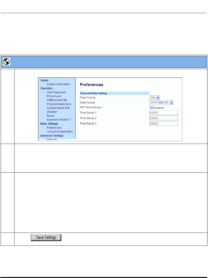
Operational Features
5-26 41-001160-03, Rev 00, Releaes 2.4
IP Phone Administrator Guide
Configuring Time and Date Using the Aastra Web UI
Use the following procedure to set a time and date, time and date format, time
zone, and daylight savings time using the Aastra Web UI.
Aastra Web UI
1 Click on Basic Settings->Preferences->Time and Date Setting.
2 In the “Time Format” field, select the time format you want to use on your phone. Valid values are:
•12h (12 hour format) (default)
•24h (24 hour format).
Note: The time displays on the phone’s idle screen in the format you select for this field.
3In the “Date Format” field, select the date format you want to use on your phone. Valid values are:
• WWW MMM DD (default)
• DD-MMM-YY
• YYYY-MM-DD
• DD/MM/YYYY
• DD/MM/YY
• DD-MM-YY
• MM/DD/YY
•MMM DD
Note: The date displays on the phone’s idle screen in the format you select for this field.
4 Click to save your changes.
Draft 1
Operational Features
41-001160-03, Rev 00, Releaes 2.4 5-27
Configuring Operational Features
Time Servers
A time server is a computer server that reads the actual time from a reference
clock and distributes this information to the clients in a network. The time server
may be a local network time server or an internet time server. The Network Time
Protocol (NTP) is the most widely used protocol that distributes and synchronizes
time in the network with the time on the time server.
On the IP phones, you can enable or disable a Time Server to be used to
synchronize time on the phones with the Timer Server you specify. An
Administrator can use the IP Phone UI, Aastra Web UI, or configuration files to
enable/disable the Time Server and specify a Time Server 1, Timer Server 2, and/
or Time Server 3. A User can enable/disable the Time Server using the IP Phone
UI or Aastra Web UI only. The Time Server is enabled by default.
Setting Time Server Using the Configuration Files
Use the following procedure to enable/disable the Time Server and optionally set
the IP Address of Time Servers 1, 2, and/or 3.
Setting Time Server Using the IP Phone UI
Use the following procedure to set the Time Server and optionally set the IP
Address of Time Servers 1, 2, and/or 3.
Configuration Files
For specific parameters you can set in the configuration files, see Appendix A, the section, “Time Server
Settings” on page A-52.
IP Phone UI
Step Action
Enable/the Time Server by specifying Time Server 1, 2, and/or 3:
1 Press on the phone to enter the Options List.
2Select Preferences->Time and Date->Time Server.
3Select Timer Server 1, Time Server 2, and/or Time Server 3.
Draft 1
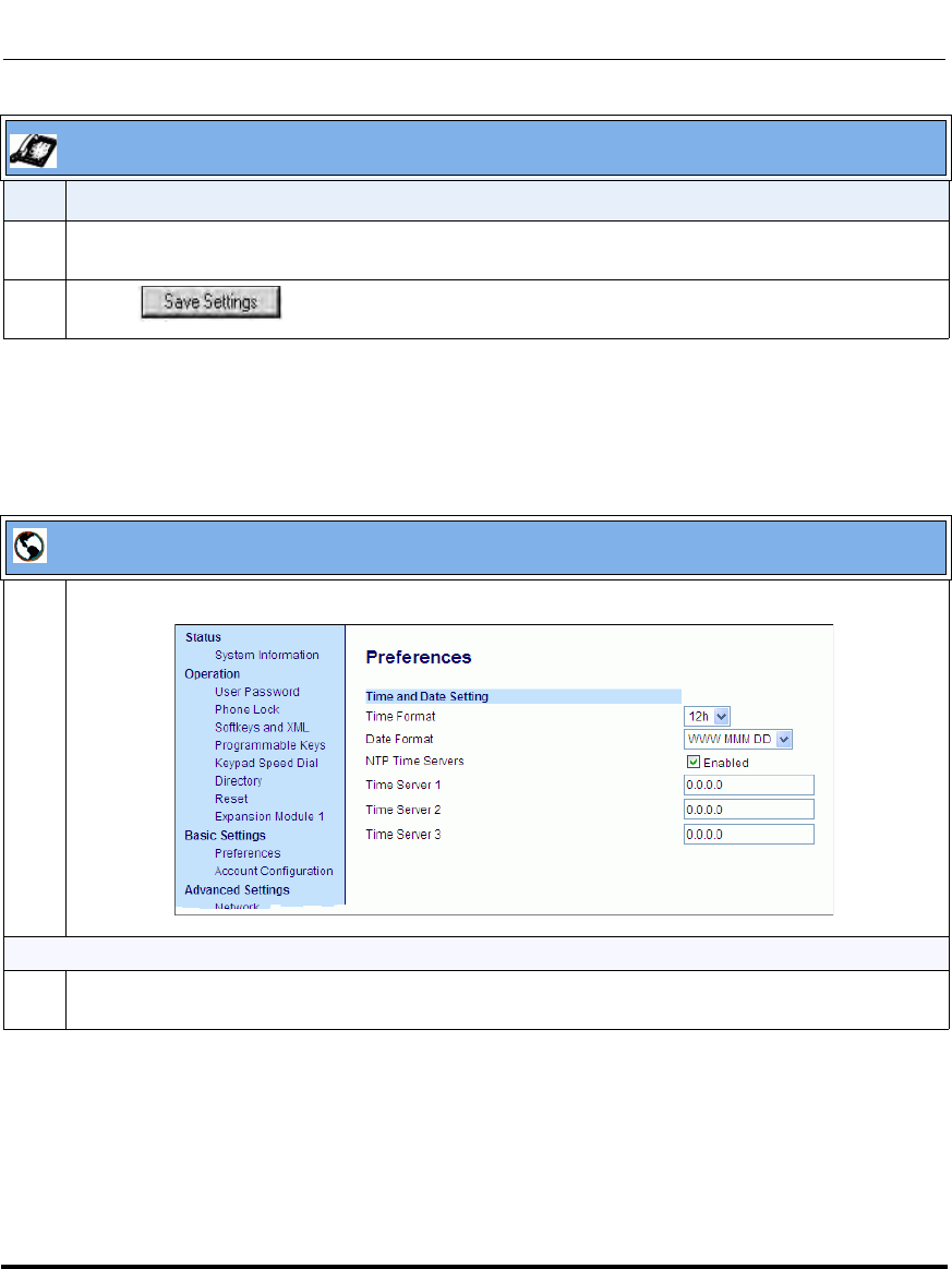
Operational Features
5-28 41-001160-03, Rev 00, Releaes 2.4
IP Phone Administrator Guide
Setting Time Server Using the Aastra Web UI
Use the following procedure to set the Time Server and optionally set the IP
Address of Time Servers 1, 2, and/or 3.
4 Enter the IP address of the Time Server, in dotted decimal format. Use the available softkeys to help
you enter the information.
5 Click to save your changes.
Aastra Web UI
1 Click on Basic Settings->Preferences->Time and Date Setting.
To enable/disable Time Server:
2The “NTP Time Server” field is enabled by default. If you need to disable the Time Server, uncheck
the box. The Time Server 1, 2, and 3 fields are grayed out when disabled.
IP Phone UI
Step Action
Draft 1
Operational Features
41-001160-03, Rev 00, Releaes 2.4 5-29
Configuring Operational Features
To set Time Server 1, 2, and/or 3:
3Note: The “Time Server” field must be enabled to enter values in the “Time Server 1, 2, and 3”
fields.
In the “Time Server 1”, “Time Server 2”, and/or “Time Server 3” field(s), enter the IP address of the
Time Server 1, 2, and/or 3 in your network, in dotted decimal format. Default for this field is 0.0.0.0.
For example, 132.234.5.4
4 Click to save your changes.
Aastra Web UI
Draft 1
Operational Features
5-30 41-001160-03, Rev 00, Releaes 2.4
IP Phone Administrator Guide
Backlight Mode (9480i, 9480i CT, 6755i, 6757i, and 6757i CT only)
The 9480i, 9480i CT, 6755i, 6757i, and 6757i CT have a backlight feature that
allows you to turn the backlight on the LCD:
• Off - Backlight is always OFF.
•Auto (Default)- Automatically turns ON the backlight when the phone is in
use, and then automatically turns OFF the backlight when the phone is idle
after a specified length of time.
“The Auto” setting sets the phone to turn off the backlighting after a period of
inactivity. The period of time that the phone waits before turning the backlight off
is also configurable.
You can set this backlight feature using the configuration files and the IP Phone
UI.
Configuring the Backlight Mode Using the Configuration Files
Use the following information to set the backlight mode and backlight timer on
the IP Phones.
Configuring the Backlight Mode Using the IP Phone UI
Use the following procedure to set the backlight mode and backlight timer on the
IP Phone using the IP Phone UI.
Configuration Files
For specific parameters you can set in the configuration files, see Appendix A, the section, “Backlight Mode
Settings (9480i, 9480i CT, 6755i, 6757i, 6757i CT)” on page A-63.
IP Phone UI
Step Action
1 Press on the phone to enter the Options List.
2Select Preferences.
3Select Display.
Draft 1
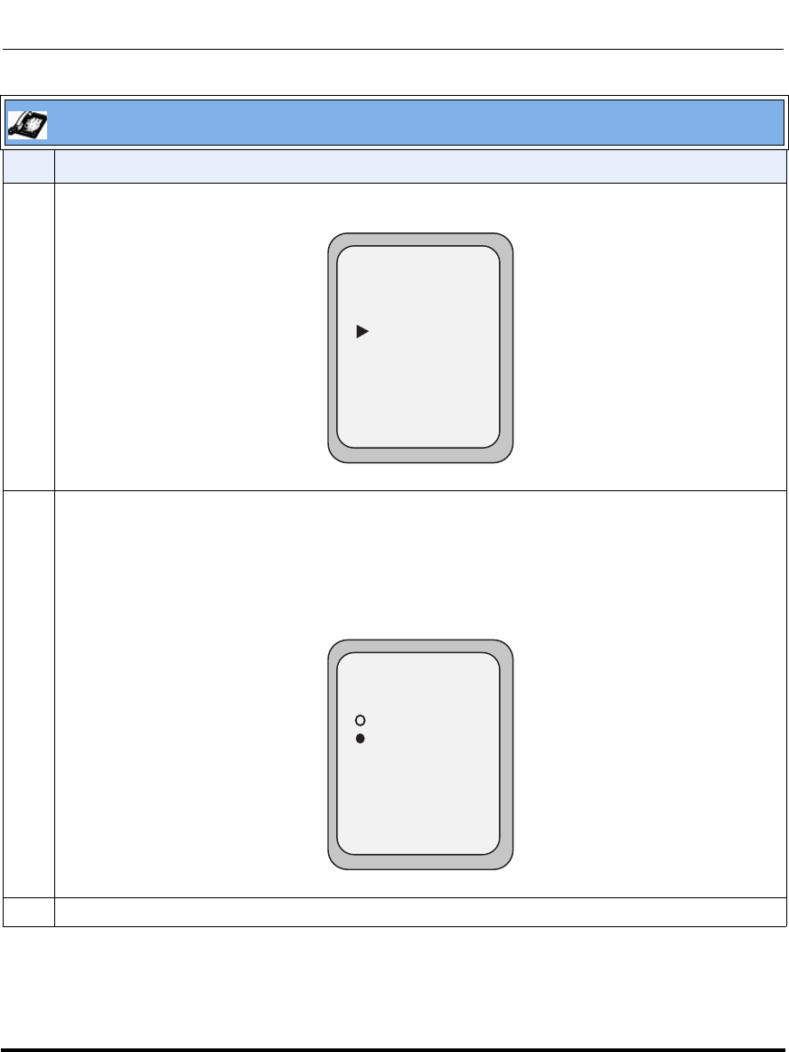
Operational Features
41-001160-03, Rev 00, Releaes 2.4 5-31
Configuring Operational Features
4Select Backlight.
5Use the UP and DOWN arrow keys to select the Backlight status for your phone.
Default is “Auto”. Valid options are:
•Off
•Auto (Default)
Note: Setting the Backlight to “Auto” displays an ADVANCED button for you to set the Auto timer.
6 If you select “Off”, press Done to save your setting.
IP Phone UI
Step Action
- Select
1. Contrast Level
2. Backlight
Display
Done -
Off
Auto
Backlight
Done -
Cancel -
Draft 1
Operational Features
5-32 41-001160-03, Rev 00, Releaes 2.4
IP Phone Administrator Guide
7 If you select “Auto”, press the Advanced softkey to set the automatic timer.
8 Using the keypad, enter the amount of seconds you want the phone to stay backlit when the phone is
idle. Valid values are 1 to 120 minutes (2 hours). Default is 10 minutes. When this period of time is
reached, the phone turns OFF the backlight. Use the "Backspace" and/or "Clear" softkeys to delete
entries if required.
9 Press Done to save your setting. The setting applies immediately to the phone.
IP Phone UI
Step Action
Off
Auto
Backlight
Done -
Cancel -
Advanced -
10 seconds
Backlight On Time
Done -
Cancel -
- Backspace
- Clear
Draft 1
Operational Features
41-001160-03, Rev 00, Releaes 2.4 5-33
Configuring Operational Features
Live Dial Pad*
The "Live Dialpad" option on the IP phone turns the Live Dial Pad mode ON or
OFF. With live dial pad ON, the IP phone automatically dials out and turns ON
Handsfree mode as soon as a dial pad key or softkey is pressed. With live dial pad
OFF, if you dial a number while the phone is on-hook, lifting the receiver or
pressing the initiates a call to that number.
*Availability of feature dependant on your phone system or service provider.
A User can turn the “Live Dialpad” ON and OFF using the IP Phone UI only. A
System Administrator can turn it ON and OFF using the IP Phone UI or the
configuration files.
Enabling/Disabling Live Dialpad Using the Configuration Files
Use the following procedure to enable/disable Live Dialpad on the IP Phones.
Enabling/Disabling Live Dialpad Using the IP Phone UI
Use the following procedure to enable/disable Live Dialpad on the IP Phones.
Configuration Files
For specific parameters you can set in the configuration files, see Appendix A, the section, “Live Dialpad
Settings” on page A-64.
IP Phone UI
Step Action
1 Press on the phone to enter the Options List.
2Select Preferences.
3Select Live Dialpad.
4On 9143i, 6751i, 6753i:
Press the UP and DOWN arrow keys to toggle the live dialpad setting ON or OFF.
On 9480i, 9480i CT, 6755i, 6757i, 6757i CT:
Press Change to toggle the live dialpad setting ON or OFF.
5 Press Done to save the setting.
Draft 1
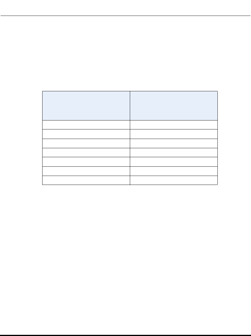
Operational Features
5-34 41-001160-03, Rev 00, Releaes 2.4
IP Phone Administrator Guide
Language
The IP phones support several different languages. You can have the IP phone UI
and the Aastra Web UI display in a specific language as required. When you set
the language to use, all of the display screens (menus, services, options,
configuration parameters, etc.) display in that language. The IP phones support
the following languages:
*German and Italian languages are not applicable to the 6757i CT cordless handset.
Loading Language Packs
You make languages available to use on the phone by loading language packs
from the configuration server to the local <MAC>.cfg configuration file. You can
use the configuration files or the Aastra Web UI to perform the download. Each
language pack consists of the IP Phone UI and Aastra Web UI translated in a
specific language.
Loading Language Packs via the Configuration File (<mac>.cfg)
Using the configuration files, you specify a language pack to load in the following
format:
lang_<ISO 639>_<ISO 3166>.txt
or
lang_<ISO 639>.txt
Available Language
Associated Language File
(included in the firmware file when
downloaded from configuration
server)
English Default (resides on the phone)
German lang_de.txt (German)*
Spanish lang_es.txt (Spanish)
Mexican Spanish lang_es_mx.txt (Mexican Spanish)
French lang_fr.txt (French)
Canadian French lang_fr_ca.txt (Canadian French)
Italian lang_it.txt (Italian)*
Draft 1

Operational Features
41-001160-03, Rev 00, Releaes 2.4 5-35
Configuring Operational Features
where <ISO 639> is the language code specified in Standard ISO 639
(see Appendix A, the section, Language Codes (from Standard ISO 639) on
page A-165) and <ISO 3166> is the country code specified in Standard ISO 3166
(see Country Codes (from Standard ISO 3166) on page A-165).
The <ISO 3166> attribute is optional.
Example
The following is an example of the parameters you would enter in the <MAC>.cfg
file to load a French, Italian, German, and Spanish language pack to the IP phone.
language 1: lang_fr_ca.txt
language 2: lang_it.txt
language 3: lang_de.txt
language 4: lang_es_mx.txt
The above entries in the <MAC>.cfg file tells the phone which language packs to
load. When the language pack(s) have loaded, you must then use the configuration
files IP Phone UI to specify which language to display on the IP phone. You must
use the Aastra Web UI to specify the language to use in the Web UI.
References
For more information about specifying the language to use, see the section,
“Specifying the Language to Use” on page 5-37.
For more information about language codes and country codes, see Appendix A,
the section, “Language Pack Settings” on page A-164.
Note: Adding/changing language packs can only be done at bootup of the
IP phone. The default language (English) cannot be changed or removed.
Draft 1
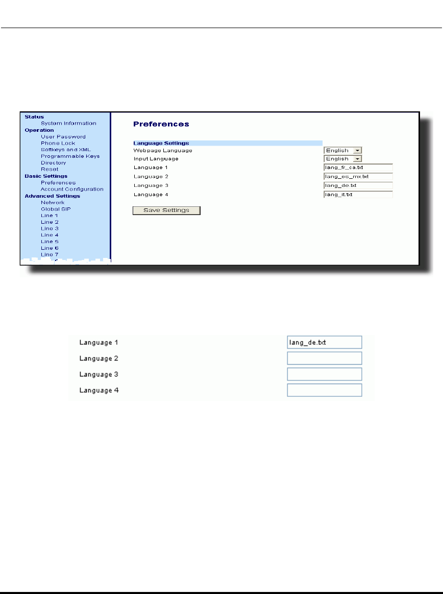
Operational Features
5-36 41-001160-03, Rev 00, Releaes 2.4
IP Phone Administrator Guide
Loading Language Packs via the Aastra Web UI
Using the Aastra Web UI, you can specify a language pack to load using the
parameters at Basic Settings->Preferences->Language Settings.
You use the following fields in the Aastra Web UI to specify which language
packs to load:
Once the language pack is loaded to the phone, it is available for selection from
either the configuration files, the IP Phone UI or the Aastra Web UI.
Draft 1
Operational Features
41-001160-03, Rev 00, Releaes 2.4 5-37
Configuring Operational Features
Specifying the Language to Use
Once the language pack(s) have loaded, you must then specify which language to
use on the phone. After the phone has booted up, you can specify which
language(s) to use. You can use the configuration files and the IP Phone UI to
specify the language for the IP Phone UI. You can use the Aastra Web UI to
specify the files for the Aastra Web UI.
Use the following procedures to specify the language to use on the IP phone.
Configuration Files
For specific parameters you can set in the configuration files, see Appendix A, the section, “Language
Settings” on page A-162 and “Language Pack Settings” on page A-164.
Notes:
1. If you specify the language to use on the phone via the
configuration files, you must reboot the phone for the changes to take
affect.
2. All languages may not be available for selection. The available
languages are dependant on the language packs currently loaded to the IP
phone.
Draft 1

Operational Features
5-38 41-001160-03, Rev 00, Releaes 2.4
IP Phone Administrator Guide
IP Phone UI
Step Action
1 Press on the phone to enter the Options List.
2Select Language.
3Select English (English), Français (French), Español (Spanish), Deutsch (German), Italiano
(Italian).
Notes:
1. Valid values for the 6757i CT cordless handset are English, French, and Spanish only.
2. All languages may not be available for selection. The available languages are dependant on the
language packs currently loaded to the IP phone. English is the default language and cannot be
changed or removed. For more information about loading language packs, see “Loading Language
Packs” on page 5-34.
4 Press Done to save the changes.
The change is dynamic. The IP phone UI displays all menu items in the language you chose.
Draft 1
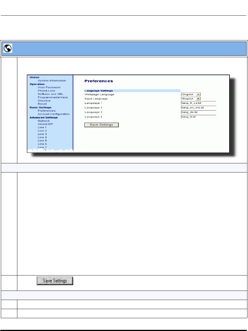
Operational Features
41-001160-03, Rev 00, Releaes 2.4 5-39
Configuring Operational Features
Aastra Web UI
1 Click on Basic Settings->Preferences->Language Settings.
Loading the Language Pack
2 In the “Language N” fields, enter the file name of the language pack you want to use to display a
specific language in the Aastra Web UI. For example, you could enter the following in the
“Language 1”, “Language 2”, “Language 3”, and “Language 4” fields to display the Aastra Web UI in
French, Spanish, German, and Italian:
lang_de.txt
lang_es.txt
lang_es_mx.txt
lang_fr.txt
lang_fr_ca.txt
lang_it.txt
Note: You must have the language pack(s) already loaded to your phone in order to use them. For
more information about loading language packs, see “Loading Language Packs” on page 5-34.
For more information about language codes and country codes, see Appendix A, the section,
“Language Pack Settings” on page A-164.
3 Click to save your changes.
Specifying the Language to Use in the Aastra Web UI
4 After restarting your phone, log back in using the Aastra Web UI.
5 Click on Basic Settings->Preferences->Language Settings.
Draft 1
Operational Features
5-40 41-001160-03, Rev 00, Releaes 2.4
IP Phone Administrator Guide
6 In the “Webpage Language” field, select a language to apply to the Aastra Web UI. The IP phone
supports the following languages:
• English (default)
• French (European French and Canadian French)
• Spanish (European Spanish and Mexican Spanish)
•German
•Italian
Notes:
1. Valid values for the 6757i CT cordless handset are English, French, and Spanish only.
2. All languages may not be available for selection. The available languages are dependant on the
language packs currently loaded to the IP phone. English is the default language and cannot be
changed or removed.
7 Click to save your changes.
The Aastra Web UI displays all screens in the language you chose.
Aastra Web UI
Draft 1
Operational Features
41-001160-03, Rev 00, Releaes 2.4 5-41
Configuring Operational Features
Specifying the Input Language to Use
The 5i Series phones support text and character inputs in various languages
(English, German, French, Spanish, and Italian).
Inputting textual or character information into the IP Phone UI, Aastra Web UI,
and XML scripts can now be done in various languages using the keypad on the
phone. The System Administrator and User can enable this feature using the
Aastra Web UI or the IP Phone UI. An Administrator can also use the
configuration files to enable this feature. Users can then use text and characters in
a specific language when performing inputs on the phone.
The following tables identify the language characters that a User can enter on the
5i Series phones that support the Input Language feature.
Keypad Input Alphabet Tables
English
Key Uppercase Characters Lowercase Characters
0 0 0
1 1.:;=_,-'&() 1.:;=_,-'&()
2 ABC2 abc2
3 DEF3 def3
4 GHI4 ghi4
5 JKL5 jkl5
6 MNO6 mno6
7 PQRS7 pqrs7
8 TUV8 tuv8
9 WXYZ9 wxyz9
* * <SPACE> * <SPACE>
# #/\@ #/\@
Draft 1

Operational Features
5-42 41-001160-03, Rev 00, Releaes 2.4
IP Phone Administrator Guide
French
Spanish
Key Uppercase Characters Lowercase Characters
0 0 0
1 1.:;=_,-'&() 1.:;=_,-'&()
2 ABC2ÀÂÇÁÅÆ abc2àâçáåæ
3 DEF3ÉÈÊË def3éèêë
4 GHI4ÎÏ ghi4îï
5 JKL5 jkl5
6 MNO6ÑÓÒÔÖ mno6ñóòôö
7 PQRS7 pqrs7
8 TUV8ÚÙÛÜ tuv8úùûü
9 WXYZ9 wxyz9
* * <SPACE> * <SPACE>
# #/\@ #/\@
Key Uppercase Characters Lowercase Characters
0 0 0
1 1.:;=_,-'&() 1.:;=_,-'&()
2 ABC2ÁÀÇ abc2áàç
3 DEF3ÉÈ def3éè
4 GHI4ÏÍ ghi4ïí
5 JKL5 jkl5
6 MNO6ÑÓÒ mno6ñóò
7 PQRS7 pqrs7
8 TUV8ÚÜ tuv8úü
9 WXYZ9 wxyz9
* * <SPACE> * <SPACE>
# #/\@ #/\@
Draft 1

Operational Features
41-001160-03, Rev 00, Releaes 2.4 5-43
Configuring Operational Features
German
Italian
Key Uppercase Characters Lowercase Characters
0 0 0
1 1.:;=_,-'&() 1.:;=_,-'&()
2 ABC2ÄÀ abc2äà
3 DEF3É def3é
4 GHI4 ghi4
5 JKL5 jkl5
6 MNO6Ö mno6ö
7 PQRS7ß pqrs7ß
8 TUV8Ü tuv8ü
9 WXYZ9 wxyz9
* * <SPACE> * <SPACE>
# #/\@ #/\@
Key Uppercase Characters Lowercase Characters
0 0 0
1 1.:;=_,-'&() 1.:;=_,-'&()
2 ABC2ÀCÇ abc2àcç
3 DEF3ÉÈË def3éèë
4 GHI4 ghi4
5 JKL5 jkl5
6 MNO6ÓÒ mno6óò
7 PQRS7 pqrs7
8 TUV8Ù tuv8ù
9 WXYZ9 wxyz9
* * <SPACE> * <SPACE>
# #/\@ #/\@
Draft 1
Operational Features
5-44 41-001160-03, Rev 00, Releaes 2.4
IP Phone Administrator Guide
Configuring Language Input Using the Configuration Files
An Administrator can specify the input language to use by entering a specific
parameter in the configuration files. An Administrator must enter the following
parameter to enable this feature:
• input language
Use the following procedures to specify the input language to use on the IP phone.
Configuring Language Input Using the IP Phone UI
Once “Language Input” is enabled, an Administrator or User can change the input
language on the phone using the IP Phone UI. The “Input Language” option
appears under the Language option in the IP Phone UI.
Example
Configuration Files
For specific parameters you can set in the configuration files, see Appendix A, the section, “Language
Settings” on page A-162.
Language
1. Screen Language
2. Input Language
- Select
Done -
Preferences
1. Tones
2. Contrast Level
3. Speed Dial Edit
4. Live Dialpad
5. Set Audio
6. Time and Date
7. Language
- Select
Done -
Input Language
1. English
2. Français
3. Español
4. Deutsch
5. Italiano
Done -
Cancel -
Language Option Input Language Option Languages Available
Draft 1
Operational Features
41-001160-03, Rev 00, Releaes 2.4 5-45
Configuring Operational Features
Use the following procedure to change the input language using the IP
Phone UI.
Aastra IP Phone UI
Step Action
1 Press the Options key.
2Select Language from the Options List.
3Select Input Language from the Language List.
4 Select the language you want to use on the IP phone for inputting text and characters. Valid values
are:
• English (default)
• Français (French)
• Español (Spanish)
• Deutsch (German) (not applicable to 6757i CT cordless handset)
• Italiano (Italian) (not applicable to 6757i CT cordless handset)
•
Note: Available input languages are dependent on the configuration enabled by your System
Administrator.
5 Press Done when you have selected a language.
Draft 1
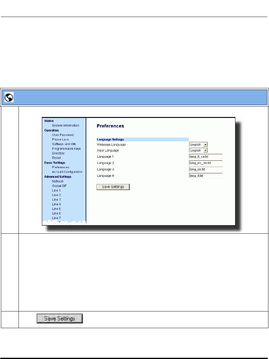
Operational Features
5-46 41-001160-03, Rev 00, Releaes 2.4
IP Phone Administrator Guide
Configuring Language Input Using the Aastra Web UI
Once “Language Input” is enabled, an Administrator or User can also change the
input language on the phone using the Aastra Web UI. The “Input Language”
option appears at the path Basic Settings->Preferences->Language Settings.
Use the following procedure to set the input language using the Aastra Web UI.
Aastra Web UI
1 Click on Basic Settings-> Preferences->Language Settings.
2 Select a language from the "Input Language" field. Setting this field allows you to specify the
language to use when entering text in the Aastra Web UI, IP Phone UI, or in XML applications on the
phone. Valid values are:
• English (default)
• Français (French)
• Español (Spanish)
• Deutsch (German) (not applicable to 6757i CT cordless handset)
• Italiano (Italian) (not applicable to 6757i CT cordless handset)
Note: Available input languages are dependent on the configuration enabled by your System
Administrator.
3 Click to save your changes.
Draft 1

Operational Features
41-001160-03, Rev 00, Releaes 2.4 5-47
Configuring Operational Features
Configuring Language Input for an XML Application
A System Administrator can enable input languages in XML applications using
the <AastraIPPhoneInputScreen> object and the “inputLanguage” attribute.
The “inputLanguage” attribute can have a value of any of the following:
• English
•French
•Français
•German
• Deutsch
• Italian
• Italiano
• Spanish
• Español
The following is an example of an XML script using the “inputLanguage”
attribute with a value of “German”.
XML Example:
<AastraIPPhoneInputScreen Beep=”Yes”inputLanguage=”German”>
<Title>Login Screen</Title>
<Prompt>User ID:</Prompt>
<Prompt>Password:</Prompt>
<URL>http://10.50.10.53/script.pl</URL>
<Parameter>UserID</Parameter>
<Parameter>Password</Parameter>
<Default></Default>
<AastraIPPhoneInputScreen>
XML Screen Example:
The screen above shows the user input of “Verwalter” in German.
LOGON-Schirm
Backspace
Done
Benutzername: Verwalter
Kennwort: *********
Dot Cancel
Draft 1
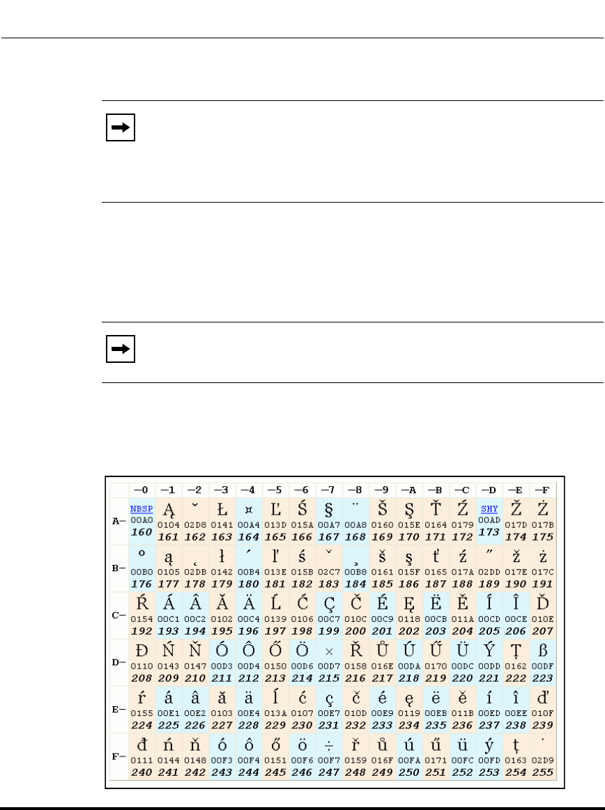
Operational Features
5-48 41-001160-03, Rev 00, Releaes 2.4
IP Phone Administrator Guide
UTF- 8 Codec for Multi-National Language Support
The IP Phones and expansion modules include support for ISO 8859-2 (Latin2) of
multi-national languages when displaying and inputing in the IP Phone UI and the
Aastra Web UI.
UTF-8 is also compatible with XML encoding on the IP Phones.
The following table illustrates the Latin 2 character set now used on the IP
Phones.
Note: If a non-supported value is used with the “inputLanguage”
attribute in the XML script, the phone uses the input language that was
configured using the Aastra Web UI or the IP Phone UI. If the parameters
are not set in the Aastra Web UI or the Phone UI, the phone uses the
default of "English".
Note: This feature is not applicable to the handsets on the 6757i CT and
the 9480i CT.
Draft 1

Operational Features
41-001160-03, Rev 00, Releaes 2.4 5-49
Configuring Operational Features
Locking IP Phone Keys
The IP phones allow you to lock or unlock programmable keys, softkeys, hard
keys, cordless handset keys, and expansion keys (for expansion modules). When
key locking is enabled, the phone uses the server settings and ignores any
previous local configuration. A user cannot override the configuration of a locked
key.
You can lock and unlock keys using the configuration files, the IP Phone UI, or
the Aastra Web UI. When viewing the locked key via the Aastra Web UI, the key
is grayed out (disabled) and cannot be changed. Locking is dynamic for XML
pushes.
You use the following “locking” parameters in the configuration files to lock the
softkeys and programmable keys on the 9143i, 9480i, 9480i CT, 6753i, 6755i,
6757i, and 6757i CT. The locking parameters impact existing softkey and
programmable key parameters as shown in the table below.
Locking Parameter Impacted Parameters Phone Model Affected
softkeyN locked softkeyN type
softkeyN label
softkeyN value
softkeyN line
softkeyN states
9480i
9480i CT
6755i
6757i
6757i CT
topsoftkeyN locked topsoftkeyN type
topsoftkeyN label
topsoftkeyN value
topsoftkeyN line
6757i
6757i CT
prgkeyN locked prgkeyN type
prgkeyN value
prgkeyN line
9143i
6753i
6755i
featurekeyN locked featurekeyN type
featurekeyN label 9480i CT
6757i CT
expmodX keyN locked expmodX keyN type
expmodX keyN value
expmodX keyN line
5-series phones only
(not applicable to the 6751i)
Draft 1
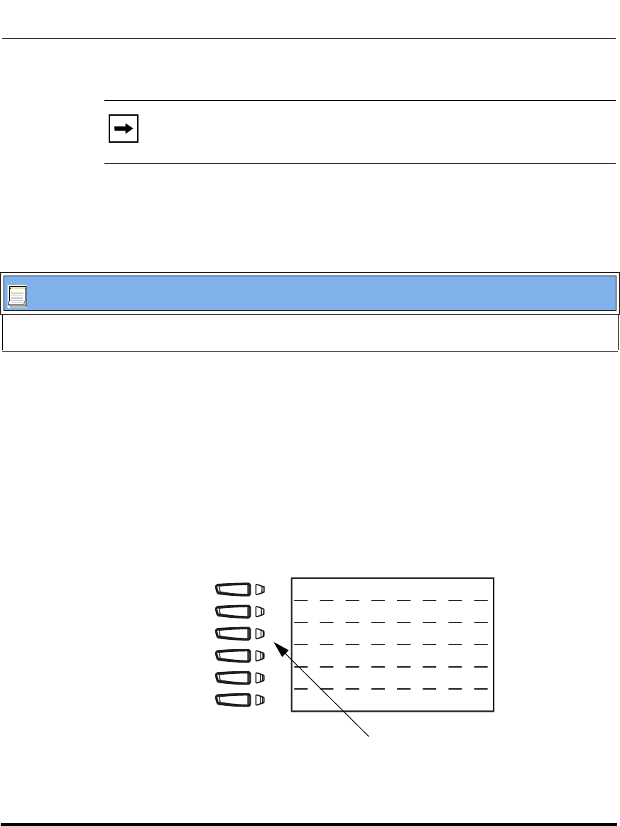
Operational Features
5-50 41-001160-03, Rev 00, Releaes 2.4
IP Phone Administrator Guide
Locking the IP Phone Keys
Use the following procedures to lock the softkeys and programmable keys on the
IP phone.
Reference
For more information about locking/unlocking the phones using the Phone UI and
Aastra Web UI, see your applicable phone-specific User Guide.
Locking/Unlocking the SAVE and DELETE keys (6753i)
There are 4 programmable keys on the 6753i phone located to the left of the paper
label. Two additional keys (SAVE and DELETE) can be made programmable by
the Administrator, providing a total of 6 programmable keys if required.
Note: The 9143i and 6753i IP phones prevent users from setting a speed
dial key via the Phone UI on a key that has been locked.
Configuration Files
For specific parameters you can set in the configuration files, see Appendix A, the section,
“Locking Softkeys and Programmable Keys” on page A-226.
Save Key
Delete Key
6753i Programmable
Keys
Directory
Callers List
Transfer
Conference
Draft 1

Operational Features
41-001160-03, Rev 00, Releaes 2.4 5-51
Configuring Operational Features
If a System Administrator unlocks the SAVE and DELETE keys, these keys can
be configured with the same functions that are available for the other
programmable keys. Only the System Administrator can unlock these keys.
The Save key allows you to save entries to the Directory and perform a Save-To
from the Callers List. It also allows you to save speeddial information to a
programmable key. You can also use the Save key while using specific XML
applications.
The Delete key allows you to remove entries from the Directory List and Callers
List. (Must enter the Directory or Callers list and select an entry, then press twice
to delete entry).
By default, the Save and Delete keys are locked so that a user can use them for
saving and deleting only. An Administrator can unlock these keys using the
configuration files, allowing the keys to be programmed with other functions if
required. An Administrator can use the following parameters in the configuration
file to lock and unlock the Save and Delete keys:
• prgkey1 locked
• prgkey2 locked
The value of "0" unlocks the keys, and the value of "1" locks the keys. The default
is "1" (lock).
The following is an example of unlocking the Save and Delete keys using the
configuration files:
Example:
• prgkey1 locked: 0
• prgkey2 locked: 0
Once the Save and Delete keys are unlocked, a User can change the function of
the keys using the Aastra Web UI. An Administrator can change the function of
the keys using the Aastra Web UI or the configuration files.
Draft 1
Operational Features
5-52 41-001160-03, Rev 00, Releaes 2.4
IP Phone Administrator Guide
IMPORTANT: If you change the functions of the Save and Delete keys, and then
an Administrator locks Keys 1 and 2, the functions are automatically set back to
the default settings of "Save" and "Delete".
Locking and Unlocking the Save and Delete Keys using the
Configuration Files.
Note: The Save and Delete functions are limited to Key 1 and Key 2 on
the 6753i IP phone only.
Configuration Files
For the specific parameter you can set in the configuration files, see Appendix A, the section, “Locking the
SAVE and DLETE Keys (6753i)” on page A-229.
Draft 1
Operational Features
41-001160-03, Rev 00, Releaes 2.4 5-53
Configuring Operational Features
Local Dial Plan
A dial plan describes the number and pattern of digits that a user dials to reach a
particular telephone number. Access codes, area codes, specialized codes, and
combinations of the number of digits dialed are all part of a dial plan. For
instance, the North American Public Switched Telephone Network (PSTN) uses a
10-digit dial plan that includes a 3-digit area code and a 7-digit telephone number.
Most PBXs support variable length dial plans that use 3 to 11 digits. Dial plans
must comply with the telephone networks to which they connect. Only totally
private voice networks that are not linked to the PSTN or to other PBXs can use
any dial plan.
The Dial Plan field accepts up to 512 characters. If a User enters a dial plan longer
than 512 characters, or a parsing error occurs, the phone uses the default dial plan
of “x+#|xx+*”. You configure the SIP Local Dial Plan using the Aastra Web UI or
the configuration files.
The IP phone SIP local dial plan available symbols are as follows:
Dial Plan Example
An example of a SIP Local Dial Plan is:
[01]XXX|[2-8]XXXX|91XXXXXX
XXXX|X+.|*XX
Symbol Description
0, 1, 2, 3, 4, 5, 6, 7, 8, 9 Digit symbol
; Allows a secondary dial tone to be audible before dialing a
number.
X Match any digit symbol (wildcard)
*, #, . Other keypad symbol
| Expression inclusive OR
+ 0 or more of the preceding digit symbol or [] expression
[] Symbol inclusive OR
- Used only with [], represent a range of acceptable symbols;
For example, [2-8]
; Used when a secondary dial tone is required on the phone.
(For example, “9;xxxxxx”, when a user has to dial “9” to get
and outside line and needs a secondary dial one presented
Draft 1
Operational Features
5-54 41-001160-03, Rev 00, Releaes 2.4
IP Phone Administrator Guide
The dial plan in the above example can accept any 4-digit dial strings that begin
with a '0' or '1', any 5-digit dial strings that begin with a '2' up to '8', any 12-digit
dial strings that begin with '91', any non-empty digit string that ends with a '.' or
any 2-digit code that begins with a '*'.
Prefix Dialing
The IP phones support a prefix dialing feature for outgoing calls.
You can manually dial a number or dial a number from a list. The phone
automatically maps the pre-configured prepended digit in the configuration, to the
outgoing number. When a match is found, the prepended digits are added to the
beginning of the dial string and the call is dialed.
You can enable this feature by adding a prepend digit(s) to the end of the Local
Dial Plan parameter string in the configuration files or the Aastra Web UI at
Basic Settings->Preferences->General.
For example, if you add a prepend map of “[2-9]XXXXXXXXX,91”, the IP
phone adds the digits “91” to any 10-digit number beginning with any digit from 2
to 9 that is dialed out. Other examples of prepend mappings are:
•1X+#,9 (Prepends 9 to any digit string beginning with “1” and terminated
with “#”.)
•6XXX,579 (Prepends “579” to any 4-digit string starting with “6”.)
•
[4-6]XXXXXX,78
(Prepends “78” to any 7-digit string starting with “4”, “5”, or “6”.)
Example
If you enter the following dial string for a local dial plan:
sip dial plan: 1+#,9
Note: The prepend digits are also added if the dialing times-out on a
partial match.
Note: You can configure a local dial plan via the configuration files or
the Aastra Web UI.
Draft 1
Operational Features
41-001160-03, Rev 00, Releaes 2.4 5-55
Configuring Operational Features
where “9” is the prepended digit, and you dial the following number:
15551212
the IP phone automatically adds the “9” digit to the beginning of the dialed
number before the number is forwarded as 915551212.
SIP Dial Plan Terminator
The IP phone allows you to enable or disable the use of the “dial plan terminator”.
When you configure the phone’s dial plan to use a dial plan terminator or timeout
(such as the pound symbol (#)) the phone waits 4 or 5 seconds after you pick up
the handset or after you finish dialing the numbers on the keypad before making
the call.
You can enable or disable the dial plan terminator using Aastra Web UI or the
configuration files.
Digit Timeout
The IP phone allows you to configure a “Digit Timeout” feature on the IP phone.
The Digit Timeout is the time, in seconds, between consecutive key presses on the
IP phone’s keypad. The default for this parameter is 4 seconds. If you press a key
on the phone and wait 4 seconds before pressing the next key, the key times out
and cancels the digit selection. You must press consecutive keys before the
timeout occurs.
Note: You can configure a local dial plan via the configuration files or
the Aastra Web UI.
Draft 1

Operational Features
5-56 41-001160-03, Rev 00, Releaes 2.4
IP Phone Administrator Guide
Secondary Dial Tone
The IP phones now support a feature that allows the user to dial a predefined dial
string, obtain a dial tone, and continue dialing. A User or Administrator can
configure this using the existing Dial Plan feature on the phone.
You can enter a new character string in the dial plan that allows you to configure
the secondary dial tone. The character string is of the form ".;." , where the period
indicates an arbitrary number of digits and the semicolon indicates that the phone
is to present a dial tone after the previous dialed digit. For example, in the string:
"9;xxxxx"
the user dials “9” to get the outside line, listens for the dial tone, and continues to
dial the applicable number. The “;” tells the phone to present a second dial tone
after the previously dialed digit. “The “xxxxx” in the example tells the phone that
a phone number is dialed after the secondary dial tone is audible.
You can enter the Secondary Dial Tone string in the Dial Plan using the
configuration files or the Aastra Web UI.
You use the following parameter in the configuration files to configure a
secondary dial tone:
• sip dial plan
Example
sip dial plan: “9;5551313”
Draft 1

Operational Features
41-001160-03, Rev 00, Releaes 2.4 5-57
Configuring Operational Features
Configuring the SIP Local Dial Plan, Dial Plan Terminator, and Digit
Timeout
Use the following procedures to configure the SIP Local Dial Plan using the
configuration files or the Aastra Web UI.
Configuration Files
For specific parameters you can set in the configuration files, see Appendix A, the section, “SIP Local Dial
Plan Settings” on page A-65.
Draft 1
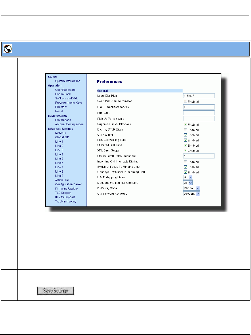
Operational Features
5-58 41-001160-03, Rev 00, Releaes 2.4
IP Phone Administrator Guide
Aastra Web UI
1 Click on Basic Settings->Preferences.
2 In the "Local Dial Plan" field, enter a valid local dial plan (up to 512 alphanumeric characters) for the
IP phone. Default is X+#|XX+*. Enter prepended digits or a “;”to present a secondary dial tone if
required.
Note: If a User enters a dial plan longer than 512 characters, or a parsing error occurs, the phone
uses the default dial plan of “x+#|xx+*”.
3 Enable the "Send Dial Plan Terminator" field by checking the check box. (Disable this field by
unchecking the box). Default is disabled.
4 In the "Digit Timeout (in seconds)" field, enter a timeout value. This is the length of time, in
seconds, he phone waits before dialing. Default is 4 seconds.
5 Click to save your changes.
Draft 1
Operational Features
41-001160-03, Rev 00, Releaes 2.4 5-59
Configuring Operational Features
Park Calls/Pick Up Parked Calls
The IP phones (including the 6757i CT handset) have a park and pickup call
feature that allows you to park a call and pickup a call when required. There are
two ways a user or administrator can configure this feature:
• Using a static configuration (globally configures park and pickup)
• Using a programmable configuration
The IP phones support the Park/Pickup feature on the Asterisk, BroadWorks,
Sylantro, and ININ PBX servers.
The following paragraph describes the park and pickup static configuration on the
IP phones.
Reference
For information on configuring the park and pickup programmable configuration
(using a key), see “Park/Pick Up Key” on page 5-234.
Park/Pickup Static Configuration (9480i, 9480i CT, 6755i, 6757i, 6757i
CT only)
Using the static method of configuring park and pickup configures these features
on a global basis for all IP phones connected in the network. You can use the
configuration files or the Aastra Web UI to configure a park/pickup static
configuration.
In the configuration files, you use the following parameters to statically configure
park/pickup:
• sprecode:
• pickupsprecode:
Note: The IP phones accept both methods of configuration. However, to
avoid redundancy, Aastra Telecom recommends you configure either a
static configuration or a programmable configuration.
Draft 1
Operational Features
5-60 41-001160-03, Rev 00, Releaes 2.4
IP Phone Administrator Guide
In the Aastra Web UI, you use the following fields at Basic Settings->
Preferences to configure park/pickup statically:
•Park Call
• Pickup Call
How It displays on the Phone
On the IP phone UI, the static configuration method displays the following:
• When a call comes in, and you pickup the handset, the default label of "Park"
displays on the first screen of the Phone UI.
• After pressing the "Park" softkey to park the call, the default label of
"Pickup" displays on the first screen of the phone UI.
The values you enter for the Park/Pickup feature are dependant on your type of
server. The following table provides the values you enter for the “sprecode” and
“pickupsprecode” parameters (configuration files), or "Park Call" and "Pickup
Parked Call" fields (Aastra Web UI).
Park/Pickup Call Server Configuration Values
*Leave "value" fields blank to disable the park and pickup feature.
Note: On the 6757i CT handset, pressing Ï displays the "Park" and
"Pickup" labels.
Server Park Values* Pickup Values*
Aasterisk 70 70
Sylantro *98 *99
BroadWorks *68 *88
ININ PBX callpark pickup
Draft 1
Operational Features
41-001160-03, Rev 00, Releaes 2.4 5-61
Configuring Operational Features
Configuring Park /Pickup using Static Configuration
(9480i, 9480i CT, 6755i, 6757i, 6757i CT only)
Use the following procedures to configure the Park/Pickup call feature using the
static configuration method.
Note: Aastra recommends you configure either the static or the
programmable configuration, but not both.
Configuration Files
For specific parameters you can set in the configuration files, see Appendix A, the section,
“Park and Pickup Global Settings (9480i, 9480i CT, 6757i/6757i CT only)” on page A-187.
Draft 1
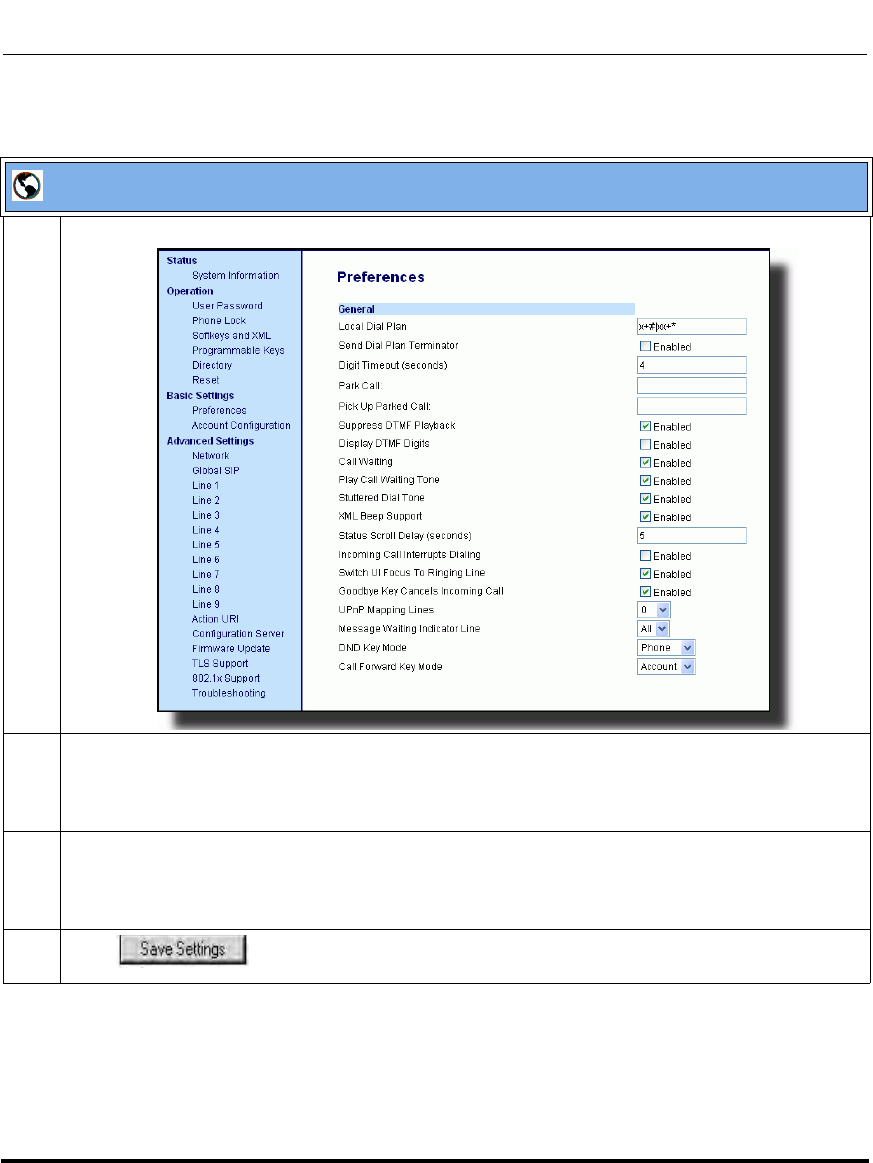
Operational Features
5-62 41-001160-03, Rev 00, Releaes 2.4
IP Phone Administrator Guide
Aastra Web UI
1 Click on Basic Settings->Preferences->General.
2 Enter a server value in the Park Call field to which incoming live calls will be parked.
Note: For values to enter in this field, see the table “Park/Pickup Call Server Configuration Values”
on page 5-60.
3 Enter a server value in the "Pickup Parked Call" field.
Note: For values to enter in this field, see the table “Park/Pickup Call Server Configuration Values”
on page 5-60.
4 Click to save your changes.
Draft 1

Operational Features
41-001160-03, Rev 00, Releaes 2.4 5-63
Configuring Operational Features
Suppressing DTMF Playback
A feature on the IP phones allows users and administrators to enable or disable the
suppression of DTMF playback when a number is dialed from the softkeys and
programmable keys.
When suppression of DTMF playback is disabled, and you press a softkey or
programmable key, the IP phone dials the stored number and displays each digit
as dialed in the LCD window.
When the suppression of DTMF playback is enabled, the IP phone dials the stored
number and displays the entire number immediately in the LCD window, allowing
the call to be dialed much faster.
DTMF playback suppression is disabled by default. Suppressing DTMF playback
can be configured using the Aastra Web UI and the configuration files.
Configuring Suppression of DTMF Playback
Use the following procedures to configure the suppression of DTMF playback on
the IP phone.
Configuration Files
For specific parameters you can set in the configuration files, see Appendix A, the section, “Suppress DTMF
Playback Setting” on page A-173.
Draft 1

Operational Features
5-64 41-001160-03, Rev 00, Releaes 2.4
IP Phone Administrator Guide
Aastra Web UI
1 Click on Basic Settings->Preferences->General.
2 Enable the "Suppress DTMF Playback" field by checking the check box.
(Disable this field by unchecking the box). Default is disabled.
3 Click to save your settings.
You must restart your IP phone for the changes to take affect.
4 Click on Operation->Reset.
5 In the "Restart Phone" field click to restart the IP phone and apply the changes.
Draft 1

Operational Features
41-001160-03, Rev 00, Releaes 2.4 5-65
Configuring Operational Features
Display DTMF Digits
A feature on the IP phones allows users and administrators to enable or disable
DTMF (dual-tone multi-frequency) digits to display to the IP phone when using
the keypad to dial, or when dialing from a softkey or programmable key.
DTMF is the signal sent from the phone to the network that you generate when
you press the phone’s touch keys. This is also known as “touchtone” dialing. Each
key you press on your phone generates two tones of specific frequencies. One
tone is generated from a high-frequency group of tones and the other from a low
frequency group.
If you enable the Display DTMF Digits parameter, the digits you are dialing from
the keypad or from a softkey or programmable key display to the IP phone’s LCD
display. This parameter is disabled by default (no digits display when dialing).
You can enable the “Display DTMF Digits” parameter using the configuration
files or the Aastra Web UI.
Configuring Display DTMF Digits
Use the following procedures to configure the suppression of DTMF playback on
the IP phone.
Configuration Files
For specific parameters you can set in the configuration files, see Appendix A, the section, “Display DTMF
Digits Setting” on page A-174.
Draft 1
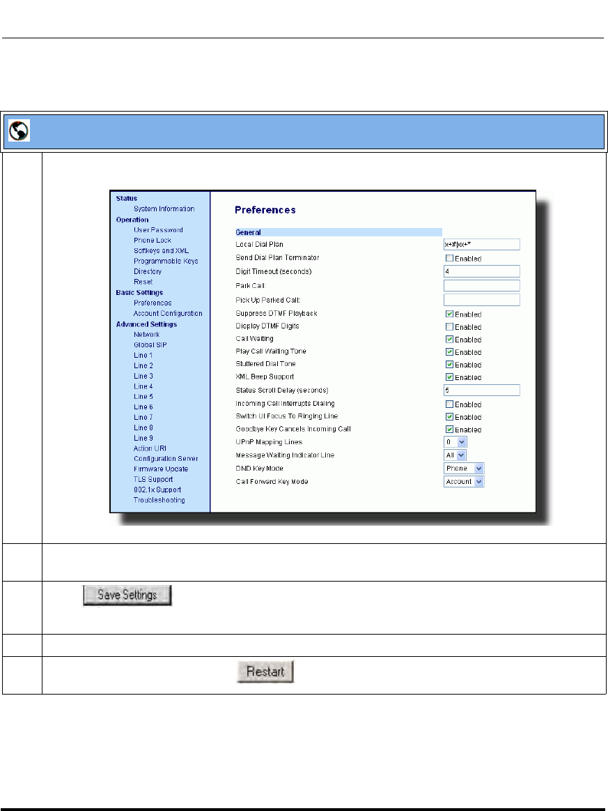
Operational Features
5-66 41-001160-03, Rev 00, Releaes 2.4
IP Phone Administrator Guide
Aastra Web UI
1 Click on Basic Settings->Preferences->General.
2 Enable the "Display DTMF Digits" field by checking the check box.
(Disable this field by unchecking the box). Default is disabled.
3 Click to save your settings.
You must restart your IP phone for the changes to take affect.
4 Click on Operation->Reset.
5 In the "Restart Phone" field click to restart the IP phone and apply the changes.
Draft 1

Operational Features
41-001160-03, Rev 00, Releaes 2.4 5-67
Configuring Operational Features
Call Waiting/Call Waiting Tone
A call waiting feature notifies the user currently on the phone, of a new incoming
call. You can disable this call waiting feature, so that the new incoming call is
automatically rejected by the phone with a busy message. A User or
Administrator can configure this feature.
If you disable call waiting on the phone, and the user is on a call, any further
incoming calls will receive busy unless “Call Forward Busy” or “Call Forward No
Answer and Busy” is configured on the phone. It will then forward the call
according to the rule configured. The phone can only:
• transfer the currently active call
or
• accept transferred calls if there is no active calls.
If call waiting is disabled:
• on the 6757i CT bases, and the handset is currently on a call, all additional
incoming calls are rejected on the handset.
• intercom calls are treated as regular incoming calls and are rejected.
• pre-dialing with live dial pad disabled still accepts incoming calls.
• the “Incoming Call Cancels Dialing” parameter is ignored because the
incoming call is automatically rejected.
• the Missed Calls List does not get updated with details of calls.
• the Blind Transfer feature on the phone may not work if two calls are made to
the phone at one time.
You can enable/disable call waiting using the configuration files or the Aastra
Web UI.
Draft 1
Operational Features
5-68 41-001160-03, Rev 00, Releaes 2.4
IP Phone Administrator Guide
Call Waiting Tone
You can also enable or disable the playing of a short “Call Waiting Tone" when
there is an incoming call on your phone. This feature is enabled by default. If you
have Call Waiting enabled, and a call comes into the line for which you are on an
active call, a tone is audible to notify you of that incoming call. The tone is also
audible to the caller to indicate to that caller you are currently on another call.
A User or Administrator can configure this feature. An Administrator can
configure this feature using the configuration files or the Aastra Web UI.
Configuring Call Waiting/Call Waiting Tone
Use the following procedures to configure the Call Waiting/Call Waiting Tone
features on the IP phone.
Note: The Call Waiting Tone feature works only if Call Waiting is
enabled.
Configuration Files
For specific parameters you can set in the configuration files, see Appendix A, the section, “Call Waiting
Settings” on page A-152.
Draft 1
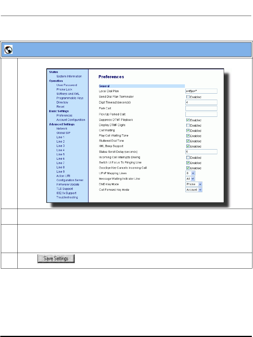
Operational Features
41-001160-03, Rev 00, Releaes 2.4 5-69
Configuring Operational Features
.
Aastra Web UI
1 Click on Basic Settings-> Preferences->General.
2The "Call Waiting" field is enabled by default. To disable this field, uncheck the box. This feature
allows you to enable or disable the call waiting feature on the IP phone.
3The "Play Call Waiting Tone" field is enabled by default. To disable this field, uncheck the box. This
feature allows you to enable or disable the call waiting tone on the IP phone.
Note: The Call Waiting Tone feature works only if the “Call Waiting” tone field is enabled.
4 Click to save your changes.
Draft 1
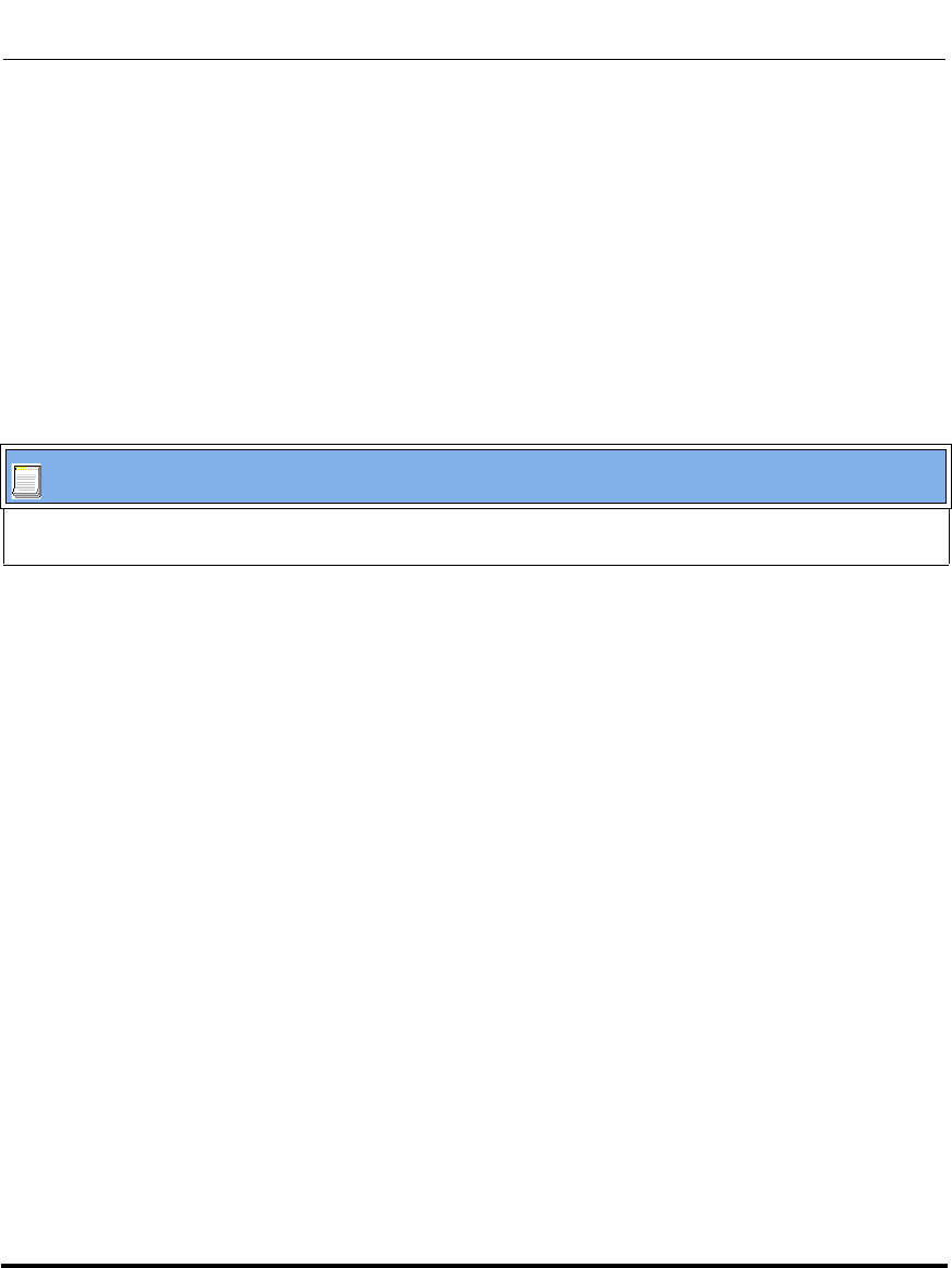
Operational Features
5-70 41-001160-03, Rev 00, Releaes 2.4
IP Phone Administrator Guide
Stuttered Dial Tone
You can enable or disable the playing of a stuttered dial tone when there is a
message waiting on the IP phone.
You can configure this feature using the configuration files and the Aastra Web
UI.
Configuring Stuttered Dial Tone
Use the following procedures to configure stuttered dial tone on the IP phones.
Configuration Files
For specific parameters you can set in the configuration files for enabling/disabling stuttered dial tone, see
Appendix A, the section, “Stuttered Dial Tone Setting” on page A-151.
Draft 1
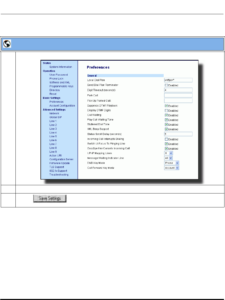
Operational Features
41-001160-03, Rev 00, Releaes 2.4 5-71
Configuring Operational Features
Aastra Web UI
1 Click on Basic Settings->Preferences->General.
2The "Stuttered Dial Tone" field is enabled by default. To disable this field, uncheck the box.
3 Click to save your changes.
Draft 1

Operational Features
5-72 41-001160-03, Rev 00, Releaes 2.4
IP Phone Administrator Guide
XML Beep Support
The IP phones have a feature that allows you to enable or disable a beep on the
phone with it receives a status message from an XML application. This beep can
be turned ON or OFF using the Aastra Web UI, the configuration files, or in an
XML script.
Reference
For more information about enabling/disabling the XML Beep Support in an
XML script, see “XML Customized Services” on page 5-311.
Configuring XML Beep Support
Use the following procedures to enable/disable XML Beep Support.
Configuration Files
For specific parameters you can set in the configuration files, see Appendix A, the section, “XML Settings”
on page A-132.
Draft 1
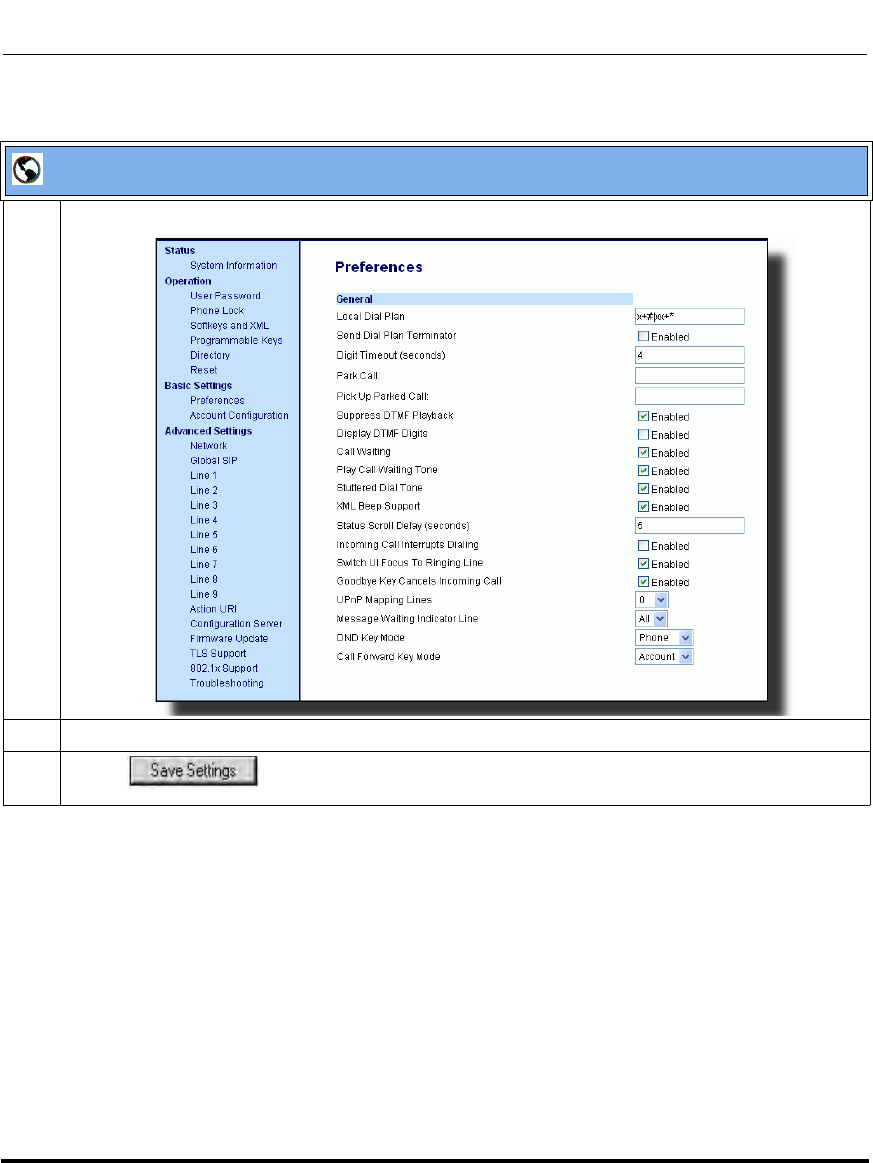
Operational Features
41-001160-03, Rev 00, Releaes 2.4 5-73
Configuring Operational Features
Aastra Web UI
1 Click on Basic Settings->Preferences->General.
2The “XML Beep Support” field is enabled by default. To disable this field, uncheck the box.
3 Click to save your changes.
Draft 1
Operational Features
5-74 41-001160-03, Rev 00, Releaes 2.4
IP Phone Administrator Guide
Status Scroll Delay
The IP phones have a feature that allows you to specify the time delay, in seconds,
between the scrolling of each status message (including XML status messages) on
the phone. The default time is 5 seconds for each message to display before
scrolling to the next message. You can configure this option via the configuration
files or the Aastra Web UI.
Reference
For more information about configuring the status scroll delay for XML status
messages, see “XML Customized Services” on page 5-311.
Configuring Status Scroll Delay
Use the following procedures to configure Status Scroll Delay.
Configuration Files
For specific parameters you can set in the configuration files, see Appendix A, the section, “XML Settings”
on page A-132.
Draft 1
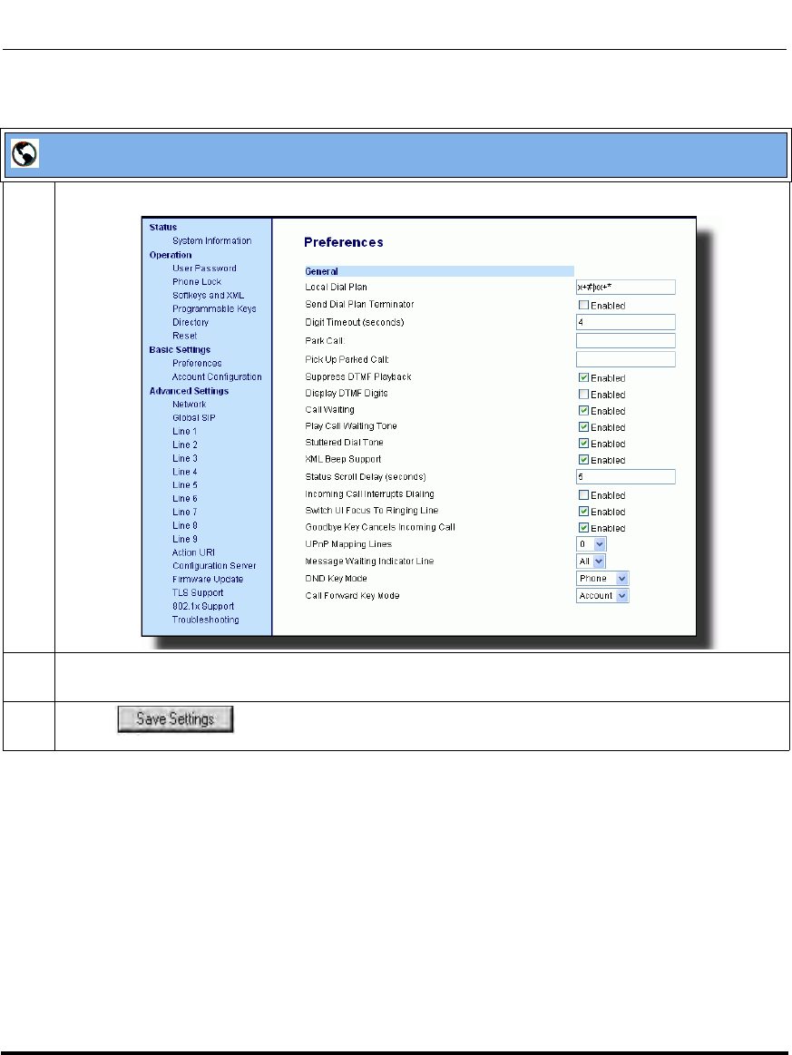
Operational Features
41-001160-03, Rev 00, Releaes 2.4 5-75
Configuring Operational Features
Aastra Web UI
1 Click on Basic Settings->Preferences->General.
2 In the “Status Scroll Delay (seconds)” field, enter a value, in seconds, that each XML status
message displays on the phone. Default is 5 seconds. Valid values are 1 to 25.
3 Click to save your changes.
Draft 1
Operational Features
5-76 41-001160-03, Rev 00, Releaes 2.4
IP Phone Administrator Guide
Incoming Call Interrupts Dialing
You can configure whether or not an incoming call interrupts an outgoing call that
is dialing. The “Incoming Call Interrupts Dialing” (Web UI) parameter or
“incoming call cancels dialing” (in config file) parameter controls this feature.
How it Works
When you enable this parameter (1 = enable), an incoming call interrupts the
outgoing call during dialing and allows the phone to ring for the user to answer the
incoming call.
When you disable this parameter (0 = disable), which is the default, the phone
does not interrupt the outgoing call during dialing and the number you were
dialing continues to display in the LCD. The phones sends the incoming call to a
free line on the phone (or sends busy signal if all remaining lines are busy) and the
LED for that line blinks. You have a choice to ignore the incoming call, or answer
the incoming call on another line, via the Ignore and Answer softkeys that
display. If you choose to answer the incoming call, you can answer the call, finish
the call, and then hang up. You can still go back to the original outgoing call and
finish dialing out.
Notes:
1. On a 9143i, 6751i, and 6753i, you must use the down arrow key to
ignore the call. To answer the call you must press the line key where the
call is coming in.
2. For all models, if you disable this parameter (0=disable), and the
phone receives an incoming call while you are dialing an outgoing call,
you can pick up the call and perform transfer or conference as required.
3. This feature works only if the User selects a line for which to dial
out. It is recommended that the Administrator always keeps Live Dialpad
ON in order for the User to have to select a line before dialing out.
Draft 1

Operational Features
41-001160-03, Rev 00, Releaes 2.4 5-77
Configuring Operational Features
Transfer/Conference Call Behavior
If you are dialing the phone to transfer or conference a call, and your phone
receives an incoming call, your dialing is never interrupted (regardless of whether
the “Incoming Call Interrupts Dialing” is enabled or disabled). For Transfer and
Conference, the incoming calls always go to an available line (other than the one
you are using for dialing) and the incoming call’s line LED blinks. The LCD still
displays your dialing screen.
Intercom Behavior
If “Incoming Call Interrupts Dialing” (Web UI) or “incoming call cancels
dialing” (config file) is enabled and you are dialing an outgoing Intercom call, the
enabled interrupt setting takes precedence over an enabled “Allow Barge In”
setting. The incoming call interrupts your dialing on an outgoing intercom call.
On an incoming intercom call, the enabled “Allow Barge In” and
“Auto-Answer” occurs while you are dialing to transfer or conference the call.
However, the incoming call goes to an available idle line, and the LED blinks
while you are dialing the second half of the conference or transfer.
If “Incoming Call Interrupts Dialing” (Web UI) or “incoming call cancels
dialing” (config file) is disabled, an incoming intercom goes to an available idle
line and the LED blinks for that line. The phone answers the call under all
conditions.
Configuring Incoming Call Interrupts Dialing
Use the following procedures to configure how the IP phone handles incoming
calls that interrupt outgoing dialing.
Configuration Files
For specific parameters you can set in the configuration files for enabling/disabling how the IP phones
handle incoming calls that interrupt outgoing dialing, see Appendix A, the section, “Incoming Call Interrupts
Dialing Setting” on page A-146.
Draft 1
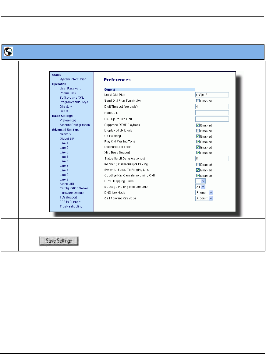
Operational Features
5-78 41-001160-03, Rev 00, Releaes 2.4
IP Phone Administrator Guide
Aastra Web UI
1 Click on Basic Settings->Preferences->General.
2 Incoming Call Interrupts Dialing is disabled by default.
If required, enable the "Incoming Call Interrupts Dialing" field by checking the check box.
3 Click to save your changes.
Draft 1
Operational Features
41-001160-03, Rev 00, Releaes 2.4 5-79
Configuring Operational Features
Switch Focus to Ringing Line
An Administrator or User can control the behavior of the phone when it receives
an incoming call when it is already in a connected call. By default, the phone
switches focus to the ringing line to enable the user to see who is calling them.
You can turn off this functionality so that the phone now stays focused on the
connected call. You can do this using the “switch focus to ringing line”
parameter in the configuration files or the Aastra Web UI.
Configuring “Switch Focus to Ringing Line”
You use the following procedures to enable or disable “Switch Focus to Ringing
Line”.
Note: If you configure the BLF/Xfer key(s) and/or Speeddial/Xfer
key(s) on the phone, you can enable or disable the switching of the
user interface focus to ringing line while the phone is in the connected
state.
Configuration Files
For specific parameters you can set in the configuration files for enabling disabling “Switch Focus to Ringing
Line”, see Appendix A, the section, “Switch Focus to Ringing Line” on page A-148.
Draft 1
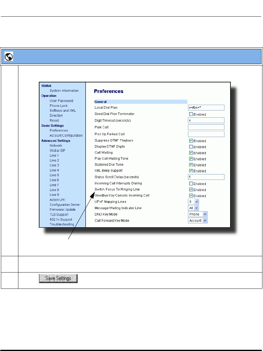
Operational Features
5-80 41-001160-03, Rev 00, Releaes 2.4
IP Phone Administrator Guide
Aastra Web UI
1 Click on Basic Settings->Preferences->General.
.
2The “Switch Focus to Ringing Line” field is enabled by default. To disable this field, uncheck the
box.
3 Click to save your changes.
“Switch Focus to Ringing Line” Parameter
Draft 1
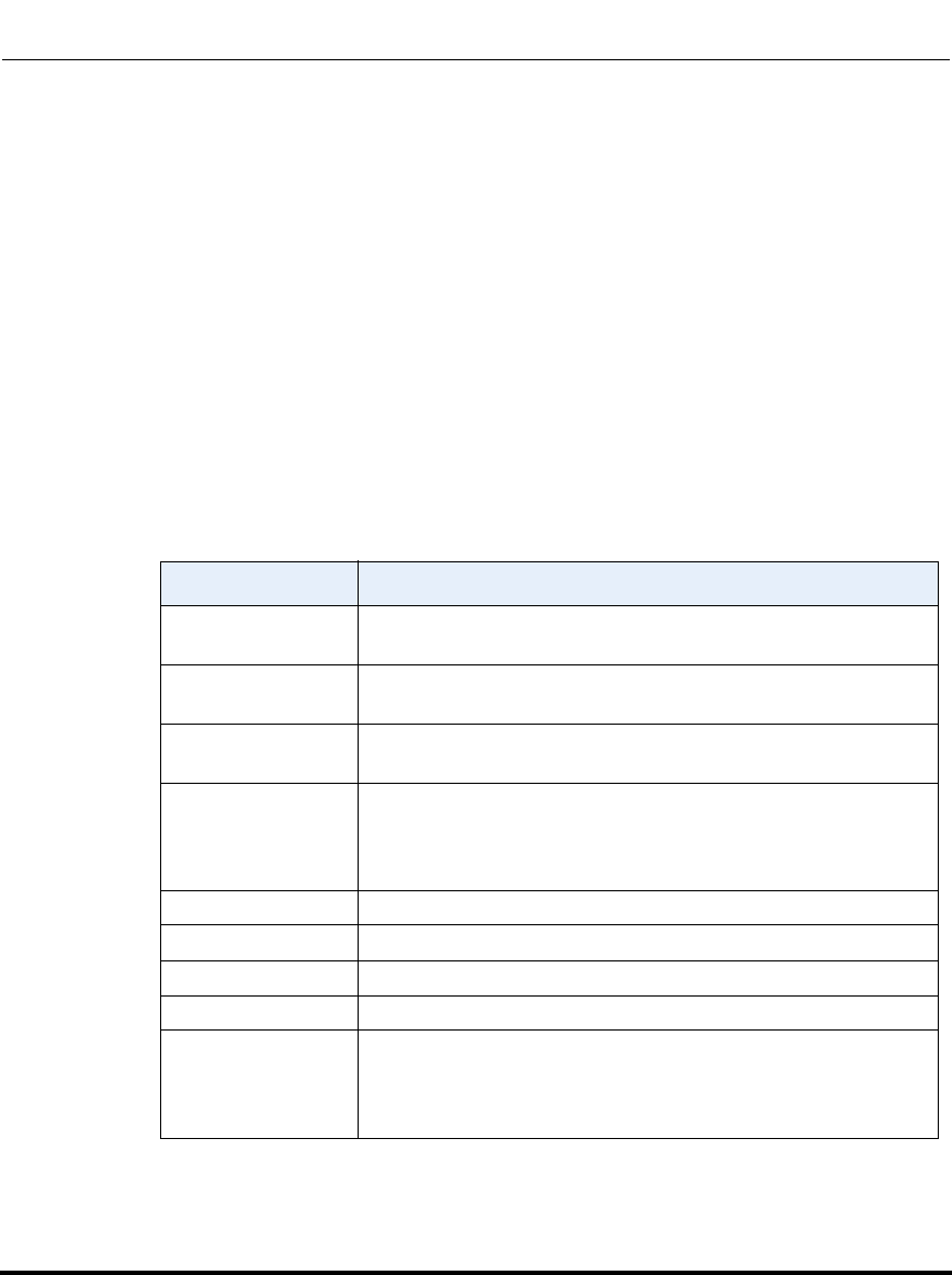
Operational Features
41-001160-03, Rev 00, Releaes 2.4 5-81
Configuring Operational Features
Preferred Line and Preferred Line Timeout
An Administrator or User can define a preferred line as well as a preferred
timeout. If a preferred line is selected, after a call ends (incoming or outgoing),
the display switches back to the preferred line. Next time you go off-hook, you
pickup on the preferred line. You can specify the number of seconds it takes for
the phone to switch back to the preferred line using the “preferred timeout”
parameter.
An Administrator can configure the “preferred line” and the “preferred
timeout” parameters using the configuration files or the Aastra Web UI. A User
can configure these parameters using the Aastra Web UI only.
The following table provides the behavior of the preferred line focus feature with
other features on the phone.
Phone Feature Preferred Line Behavior
call return The phone switches back to the focused line immediately after
the call ends.
speeddial The line is already specified when the speeddial is created. The
phone switches back immediately after the call ends.
conference For incoming calls, the phone switches back immediately after
the call ends.
transfer For incoming or outgoing calls, the current behavior is that the
same line used to transfer the call does not change. For incoming
calls, the phone switches back immediately after the call
transfers.
blf The phone switches back immediately after the call ends.
park The phone switches back immediately after the call ends.
voicemail The phone switches back immediately after the call ends.
redial The phone switches back immediately after the call ends.
dialing For incomplete dialing on a non-preferred line, the focus does not
change if some digits are entered.
If no digits are entered or digits were cleared, the focus changes
to preferred line after the time out has passed without activities.
Draft 1

Operational Features
5-82 41-001160-03, Rev 00, Releaes 2.4
IP Phone Administrator Guide
Configuring the Preferred Line and Preferred Line Timeout
You use the following procedures to configure the Preferred Line and the
Preferred Line Timeout on the IP Phones.
caller id If the "Switch UI Focus To Ringing Line" parameter is disabled,
the User is able to see the Caller ID when the phone switches the
focus to the ringing line.
factory default Factory default and recovery mode clears the "preferred line" and
"preferred line timeout" parameters, and the phone operates in a
non-preferred line mode.
Notes:
1. If you specify a value of “0” for the preferred line parameter, it
disables the preferred line focus feature.
2. If you specify a value of “0” for the preferred line timeout
parameter, the phone returns the line to the preferred line immediately.
Configuration Files
For specific parameters you can set in the configuration files for configuring the Preferred Line and Preferred
Line Timeout, see Appendix A, the section, “Preferred Line and Preferred Line Timeout” on page A-149.
Phone Feature Preferred Line Behavior
Draft 1
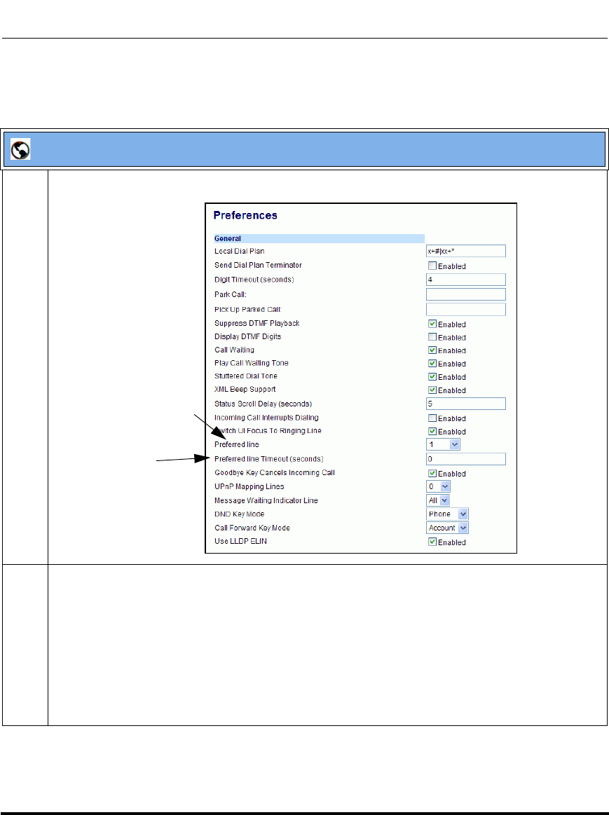
Operational Features
41-001160-03, Rev 00, Releaes 2.4 5-83
Configuring Operational Features
Use the following parameters to configure preferred line focus using the Aastra
Web UI.
Aastra Web UI
1 Click on Basic Settings->Preferences->General.
2 In the “Preferred Line” field, select a preferred line to switch focus to after incoming or outgoing
calls end on the phone. Valid values are:
•None (disables the preferred line focus feature)
•1 to 9
Default is 1.
For example, if you set the preferred line to “1”, when a call (incoming or outgoing) ends on the
phone (on any line), the phone switches focus back to Line 1.
Preferred Line
Preferred Line
Timeout
Draft 1
Operational Features
5-84 41-001160-03, Rev 00, Releaes 2.4
IP Phone Administrator Guide
3 In the “Preferred Line Timeout” field, enter the amount of time, in seconds, that the phone
switches back to the preferred line after a call (incoming or outgoing) ends on the phone, or after a
duration of inactivity on an active line. Default is 0. Valid values are:
• 0 to 999
4 Click to save your changes.
Aastra Web UI
Draft 1

Operational Features
41-001160-03, Rev 00, Releaes 2.4 5-85
Configuring Operational Features
Goodbye Key Cancels Incoming Call
You can configure the Goodbye key to drop active calls or ignore incoming calls
using the “goodbye cancels incoming call” parameter. This parameter controls
the behavior of the goodbye key when the phone is on an active call and a second
call is presented to the phone.
How it Works
When you enable this parameter (1 = enable in the configuration files), which is
the default, the Goodbye key rejects the incoming call. When you disable this
parameter (0 = disable in the configuration files), the Goodbye key hangs up the
active call.
For the 9480i, 9480i CT, 6755i, 6757i, and 6757i CT:
If you enable this parameter, and the phone receives another call when an active
call is already present, the phone displays softkey 1 as “answer” and softkey 2 as
“ignore”. You can press the required softkey as applicable.
For the 9143i, 6751i, 6753i:
If you enable this parameter, and the phone receives another call when an active
call is already present, the “ignore” option only displays in the LCD window. The
phone ignores the incoming call. If you press the DOWN arrow key, the phone
answers the incoming call.
You can set this parameter using the configuration files or the Aastra Web UI.
Configuring the Goodbye Key to Cancel Incoming Calls
Use the following procedures to configure the behavior of the Goodbye Key on
the IP phone.
Configuration Files
For specific parameters you can set in the configuration files for enabling/disabling the behavior of the
Goodbye Key, see Appendix A, the section, “Incoming Call Interrupts Dialing Setting” on page A-146.
Draft 1
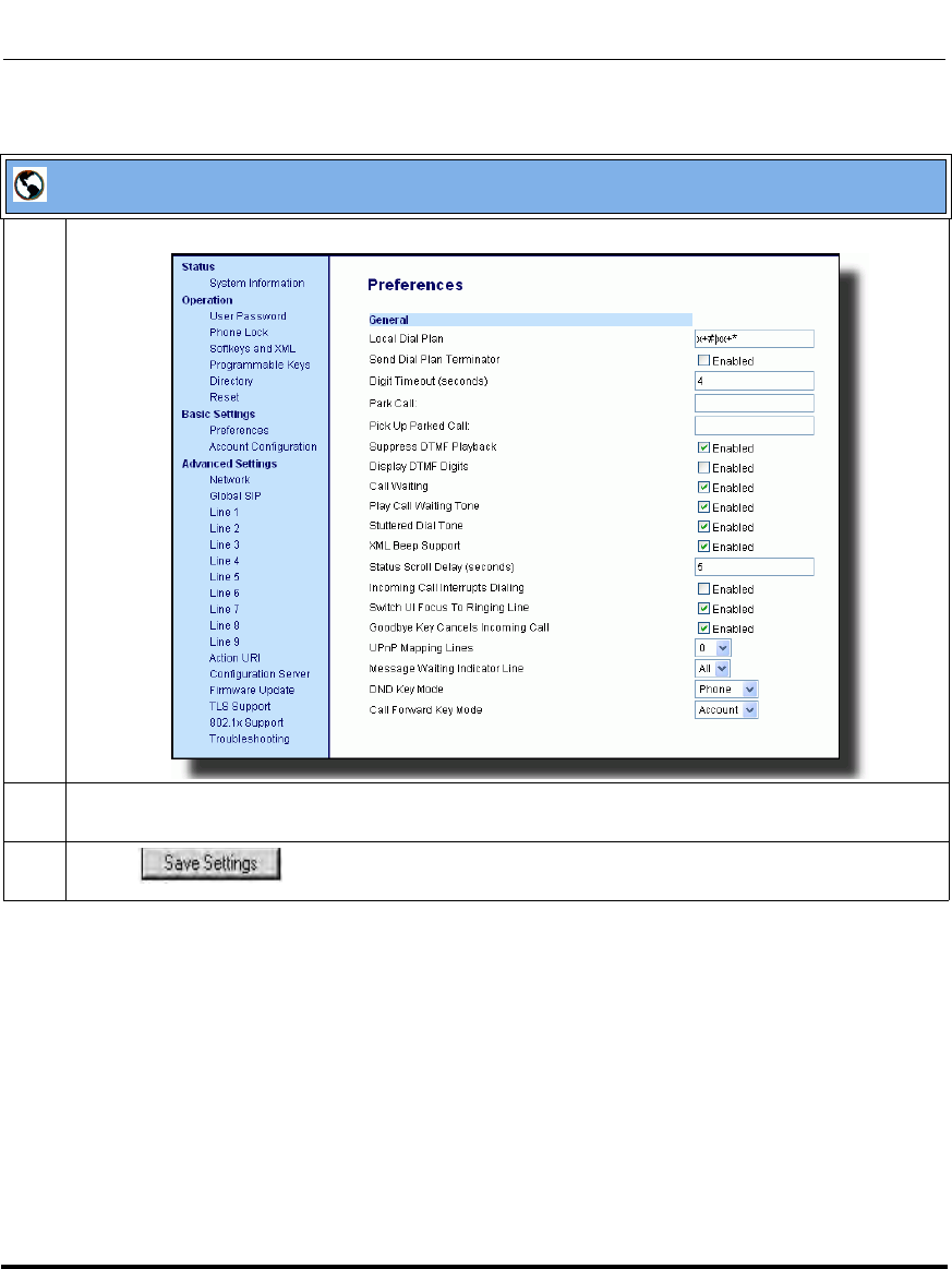
Operational Features
5-86 41-001160-03, Rev 00, Releaes 2.4
IP Phone Administrator Guide
Aastra Web UI
1 Click on Basic Settings->Preferences->General.
2 Incoming Call Interrupts Dialing is disabled by default.
If required, enable the "Incoming Call Interrupts Dialing" field by checking the check box.
3 Click to save your changes.
Draft 1
Operational Features
41-001160-03, Rev 00, Releaes 2.4 5-87
Configuring Operational Features
UPnP Mapping Lines (for remote phones)
Universal Plug and Play (UPnP) is a standard that uses Internet protocols to
enable devices to be plugged into a network and automatically know about each
other. With UPnP, when a user plugs a device into the network, the device
configures itself, acquires a TCP IP address, and uses a discovery protocol based
on the Internet's HTTP or HTTPS URL to announce its presence on the network
to other devices.
This method of device discovery on a network is called “Universal Plug and Play”
or UPnP. If you enable UPnP, and the phone is discovered on the network, port
mappings are set up between the phone and the Internet Gateway Device (IGD) in
your network. The phone controls the opening, closing, and polling of ports on the
IGD. HTTP and SIP use a single port each. RTP/RTCP uses a range of ports.
You can enable the UPnP mappings to specific lines on your phone. You set this
configuration using the Aastra Web UI at Basic Settings->Preferences->UPnP
Mapping Lines.
Configuring UPnP Mapping Lines
Use the following procedures to configure UPnP mapping on specific lines on the
IP phone.
Note: UPnP must be enabled on your remote phone before you can
configure the UPnP mapping lines. For information on enabling/disabling
UPnP see Chapter 4, the section, “Universal Plug and Play (UPnP) (for
remote phones)” on page 4-50.
Configuration Files
For specific parameters you can set in the configuration files, see Appendix A, the section, “UPnP Settings”
on page A-37.
Draft 1
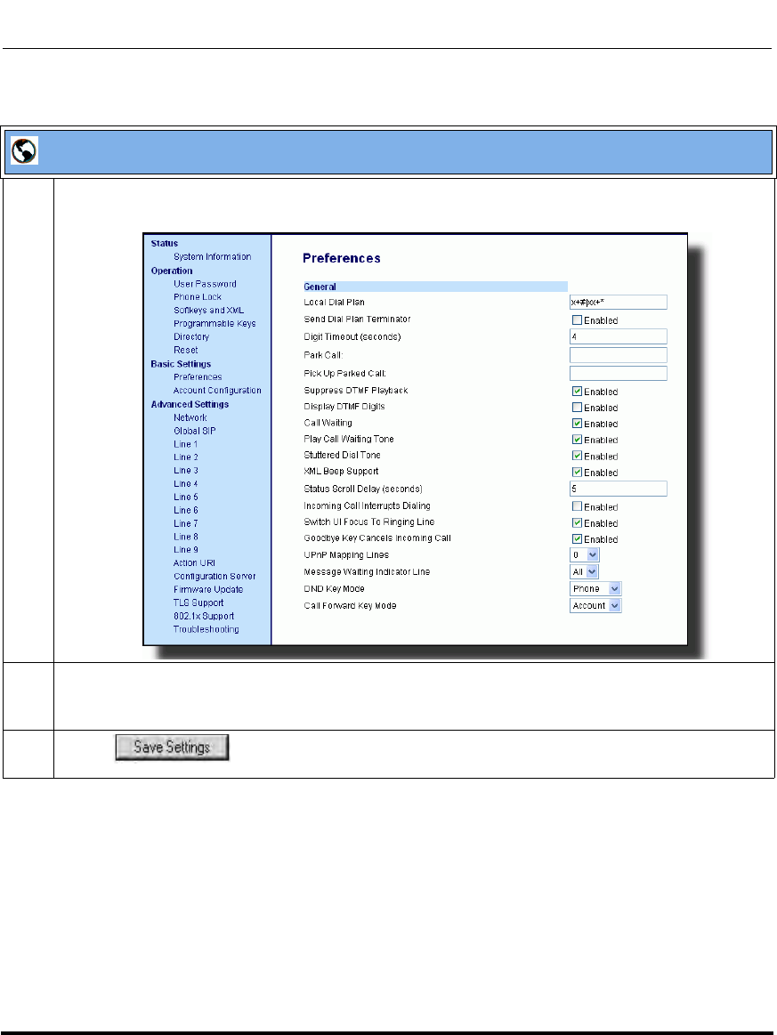
Operational Features
5-88 41-001160-03, Rev 00, Releaes 2.4
IP Phone Administrator Guide
Aastra Web UI
1 Click on Basic Settings->Preferences->General.
2The "UPnP Mapping Lines" field is set to 0 by default. If required, change the setting to a specific
line by selecting a line from the list. Valid values are 0 through 10. The line you select is the line that
your remote phone uses to perform Universal Plug and Play on the network you are connecting to.
3 Click to save your changes.
Draft 1

Operational Features
41-001160-03, Rev 00, Releaes 2.4 5-89
Configuring Operational Features
Message Waiting Indicator Line
A User or Administrator can configure the Message Waiting Indicator (MWI) to
illuminate for a specific line or for all lines. For example, if you configure the
MWI LED on line 3 only, the LED illuminates if a voice mail is pending on line 3.
If you configure the MWI LED for all lines, the LED illuminates if a voice mail is
pending on any line on the phone (lines 1 through 9).
A User can configure the MWI using the Aastra Web UI only. An Administrator
can configure the MWI on single or all lines using the configuration files or the
Aastra Web UI.
Configuring Message Waiting Indicator (MWI)
Use the following procedures to configure MWI on the IP phone.
Configuration Files
For specific parameters you can set in the configuration files, see Appendix A, the section, “Message
Waiting Indicator Settings” on page A-153.
Draft 1
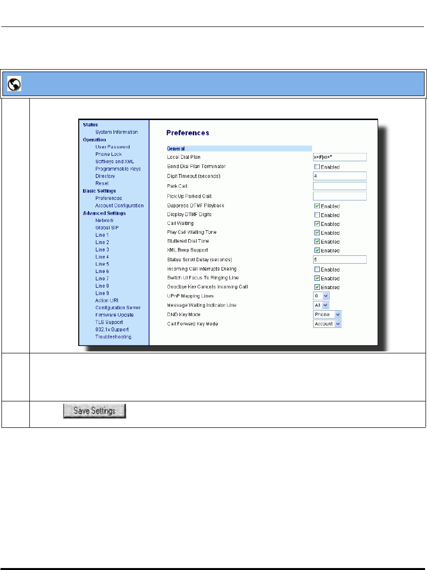
Operational Features
5-90 41-001160-03, Rev 00, Releaes 2.4
IP Phone Administrator Guide
Aastra Web UI
1 Click on Basic Settings-> Preferences->General.
2 In the “Message Waiting Indicator Line” field, select a single line from 1 to 9, or select “All” for all
lines. If you select a single line, the MWI illuminates when a voice mail message is pending on that
line. If you select all lines, the MWI illuminates when a voice mail message is pending on any line
from 1 to 9.
3 Click to save your changes.
Draft 1
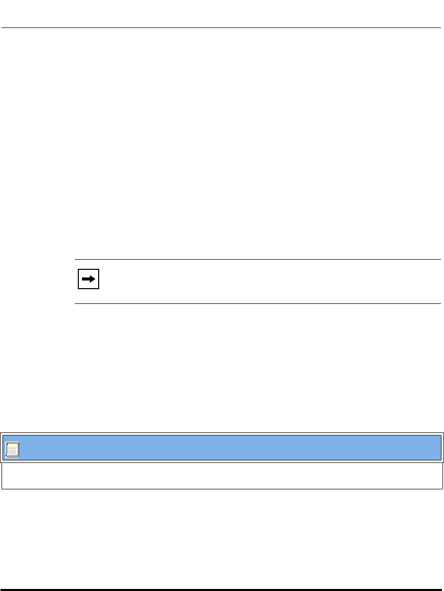
Operational Features
41-001160-03, Rev 00, Releaes 2.4 5-91
Configuring Operational Features
DND Key Mode
The IP phones have a feature you can enable called "Do not Disturb (DND). An
Administrator or User can set “do not disturb” based on the accounts on the phone
(all accounts or a specific account). You can set specific modes for the way you
want the phone to handle DND. The three modes you can set on the phone for
DND are:
• Account
• Phone
•Custom
An Administrator or User can set the DND mode using the Aastra Web UI at the
path Basic Settings->Preferences->General->DND Key Mode. An Administrator
can also set the DND Key Mode using the configuration files.
Reference
For more information about how DND works and how you can use it on the
phones, see the section, “Do Not Disturb (DND)” on page 5-211.
Configuring the DND Key Mode
Use the following procedures to set the DND Key Mode on the phone.
Note: You must configure a DND key on the phone to use this feature.
Configuration Files
For specific parameters you can set in the configuration files, see Appendix A, the section, “DND Key Mode
Settings” on page A-154.
Draft 1
Operational Features
5-92 41-001160-03, Rev 00, Releaes 2.4
IP Phone Administrator Guide
Aastra Web UI
1 Click on Basic Settings->Preferences->General.
2 In the “DND Key Mode” field, select a “do not disturb” (DND) mode to use on the phone.
Valid values are: Account, Phone, Custom. Default is Phone.
•account Sets DND for a specific account. DND key toggles the account in focus on the
IP Phone UI, to ON or OFF.
•phone Sets DND ON for all accounts on the phone. DND key toggles all accounts on the
phone to ON or OFF.
•custom Sets the phone to display custom screens after pressing the DND key, that list the
account(s) on the phone. The user can select a specific account for DND, turn
DND ON for all accounts, or turn DND OFF for all accounts.
Notes:
1. If there is only one account configured on the phone, then the mode setting is ignored and the
phone behaves as if the mode was set to “Phone”.
2. Using the Aastra Web UI, if you change the DND Key Mode to “phone”, all accounts
synchronize to the current setting of Account 1.
DND Key Mode
Parameter
Draft 1

Operational Features
41-001160-03, Rev 00, Releaes 2.4 5-93
Configuring Operational Features
Reference
For more information, see the section, “Do Not Disturb (DND)” on page 5-211.
Call Forward Mode
Call Forward (CFWD) on the IP phone allows incoming calls to be forwarded to
another destination. The phone sends the SIP message to the SIP proxy, which
then forwards the call to the assigned destination.
An Administrator or User can configure CFWD on the phone-side by setting a
mode for the phone to use (Account, Phone, or Custom). Once the mode is set,
you can use the IP Phone UI to use the CFWD feature at Options->Call Forward
or by pressing a configured Call Forward softkey/programmable key/extension
module key.
The following describes the behavior for each CFWD mode.
•Account mode - The account mode allows you to configure CFWD on a per
account basis. Pressing a configured CFWD key applies to the account in
focus.
•Phone mode - The Phone mode allows you to set the same CFWD
configuration for all accounts (All, Busy, and/or No Answer). When you
configure the initial account, the phone applies the configuration to all other
accounts. (In the Aastra Web UI, only the account you configured is enabled.
All other accounts are grayed out but set to the same configuration.) Using the
Aastra Web UI, if you make changes to that initial account, the changes apply
to all accounts on the phone.
3 Configure a DND key on the phone using the procedures in the section, “Do Not Disturb (DND)” on
page 5-211.
4 Click to save your changes.
The change takes effect immediately without a reboot.
Aastra Web UI
Draft 1
Operational Features
5-94 41-001160-03, Rev 00, Releaes 2.4
IP Phone Administrator Guide
•Custom mode - The Custom mode allows you to configure CFWD for a
specific account or all accounts. You can configure a specific mode (All,
Busy, and/or No Answer) for each account independently or all accounts. On
the 9143i, 6751i, and 6753i phones, you can set all accounts to ALL On or
ALL Off. On the 9480i, 9480i CT, 6755i, 6757i, and 6757i CT, you can set all
accounts to All On, All Off, or copy the configuration for the account in focus
to all other accounts using a CopytoAll softkey.
The states you can set for Call Forward are All, Busy, No Answer. You can enable
different call forwarding rules/modes independently (for example, you can set
different phone numbers for Busy, All, and NoAns modes and then turn them on/
off individually. The behavior of these states is dependent on the mode (account,
phone, or custom) you configure on the phone.
Reference
For more information about how Call Forwarding works and how you can use it
on the IP Phones, see “Call Forwarding” on page 5-249.
Configuring Call Forward Key Mode
Use the following procedures to set the Call Forward key mode on the IP phones.
Note: If there is only one account configured on the phone, then the
mode setting is ignored and the phone behaves as if the mode was set
to “Phone”.
Configuration Files
For specific parameters you can set in the configuration files, see Appendix A, the section, “Call Forward
Key Mode Settings” on page A-127.
Draft 1
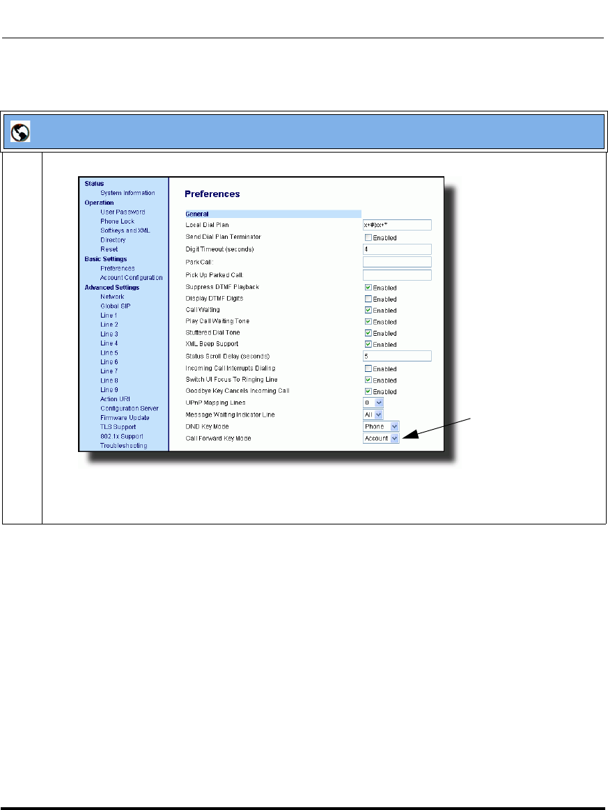
Operational Features
41-001160-03, Rev 00, Releaes 2.4 5-95
Configuring Operational Features
Aastra Web UI
1 Click on Basic Settings->Preferences->General.
Note: If there is no CFWD key configured on the phone or it is removed, you can still configure Call
Forwarding via the IP Phone UI at the path Options->Call Forward.
Call Forward
Key Mode
Parameter
Draft 1

Operational Features
5-96 41-001160-03, Rev 00, Releaes 2.4
IP Phone Administrator Guide
Reference
For more information, see the section, “Call Forwarding” on page 5-249.
2 In the “Call Forward Key Mode” field, select a call forward mode to use on the phone.
Valid values are: Account, Phone, Custom. Default is Account.
•account
The account mode allows you to configure CFWD on a per account basis. Pressing a configured
CFWD key applies to the account in focus.
•phone
The Phone mode allows you to set the same CFWD configuration for all accounts (All, Busy,
and/or No Answer). When you configure the initial account, the phone applies the configuration
to all other accounts. (In the Aastra Web UI, only the account you configured is enabled. All other
accounts are grayed out but set to the same configuration.) Using the Aastra Web UI, if you make
changes to that initial account, the changes apply to all accounts on the phone.
•custom
The Custom mode allows you to configure CFWD for a specific account or all accounts. You can
configure a specific state (All, Busy, and/or No Answer) for each account independently or all
accounts. On the 9143i, 6751i, and 6753i phones, you can set all accounts to ALL On or ALL
Off. On the 9480i, 9480i CT, 6755i, 6757i, and 6757i CT, you can set all accounts to All On, All
Off, or copy the configuration for the account in focus to all other accounts using a CopytoAll
softkey.
Notes:
1. If there is no CFWD key configured on the phone or it is removed, you can still set the CFWD
modes via the IP Phone UI at the path Options->Call Forward.
2. If there is only one account configured on the phone, then the mode setting is ignored and the
phone behaves as if the mode was set to “Phone”.
3. When configuring a CFWD state (All, Busy, No Answer) for an account, you must configure a
CFWD number for that state in order for the state to be enabled.
3 Click to save your changes.
The change takes effect immediately without a reboot.
Aastra Web UI
Draft 1

Operational Features
41-001160-03, Rev 00, Releaes 2.4 5-97
Configuring Operational Features
Link Layer Discovery Protocol for Media Endpoint Devices (LLDP-MED)
and Emergency Location Identification Number (ELIN)
The IP Phones support Link Layer Discovery Protocol for Media Endpoint
Devices (LLDP-MED). LLDP-MED is designed to allow for things such as:
• Auto-discovery of LAN policies (such as VLAN, Layer 2 Priority and
Diffserv settings) leading to "plug and play" networking.
• Extended and automated power management of Power over Ethernet
endpoints.
• Inventory management, allowing network administrators to track their
network devices, and determine their characteristics (manufacturer, software
and hardware versions, serial / asset number).
On the IP Phones, LLDP-MED performs the following:
• Supports the MAC/PHY configuration (e.g. speed rate/duplex mode).
• Supports VLAN info from the network policy; this takes precedence over
manual settings.
• Allows you to enable/disable LLDP-MED if required.
• Allows you to configure time interval between successive LLDP Data Unit
(LLDPDU) frames.
• Allows LLDP packets to be received from the LAN port.
• Allows the phone to use the location information, Explicit Congestion
Notification (ECN) Emergency Location Identification Number (ELIN), sent
by the switch, as a caller ID for making emergency calls.
Note: If the phone receives location information in ECN ELIN format
(10 to 25 numeric string), the phone replaces the caller ID SIP header
with the ECN ELIN value and the SIP URI does not change. The phone
determines if this is an emergency number by checking the emergency
dial plan configured on the phone.
Draft 1
Operational Features
5-98 41-001160-03, Rev 00, Releaes 2.4
IP Phone Administrator Guide
The following table identifies the configuration parameters for LLDP and ELIN
and which method you can use to configure each parameter. This table also
indicates whether the parameters can be configured by an Administrator, a User,
or both.
Configuring LLDP-MED and ELIN
Use the following procedures to configure LLDP-MED and ELIN on the IP
phones.
Use the following procedure to enable/disable LLDP-MED using the IP Phone
UI.
Parameter Method of Configuration Who Can Configure
lldp Configuration Files Administrator
lldp interval Configuration Files Administrator
use lldp elin Configuration Files Administrator
LLDP Support IP Phone UI Administrator
LLDP Aastra Web UI Administrator
LLDP Packet Interval Aastra Web UI Administrator
LLDP ELIN Aastra Web UI Administrator and User
Configuration Files
For specific parameters you can set in the configuration files, see Appendix A, the section, “LLDP-MED and
ELIN Settings” on page A-129.
Note: You cannot configure the “LLDP Interval” or the “Use LLDP
ELIN” parameters via the IP Phone UI.
Draft 1
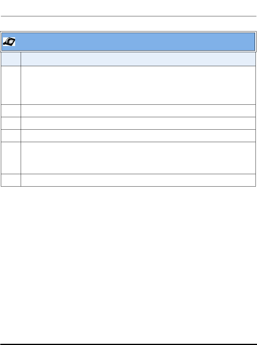
Operational Features
41-001160-03, Rev 00, Releaes 2.4 5-99
Configuring Operational Features
Aastra IP Phone UI
Step Action
1 Press Options, and then select Administrator Menu.
On the 6751i:
Press Services, and then select Options->Administrator Menu.
2 Select Network Settings.
3 Select Ethernet & VLAN.
4 Select LLDP Support.
5 Press CHANGE to toggle the LLDP setting to Enabled or Disabled.
This field enables or disables Link Layer Discovery Protocol for Media Endpoint Devices
(LLDP-MED) on the IP Phone.
6 Press DONE to save the change.
Draft 1
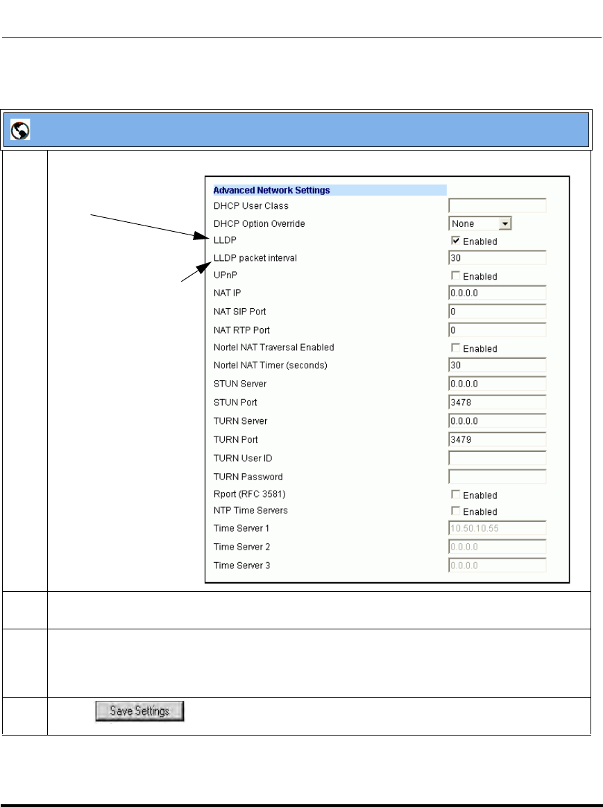
Operational Features
5-100 41-001160-03, Rev 00, Releaes 2.4
IP Phone Administrator Guide
Use the following procedure to configure LLDP-MED using the Aastra Web UI:
Aastra Web UI
1 Click on Advanced Settings->Network->Advanced Network Settings.
2 The “LLDP” field is enabled by default. To disable LLDP, click the check mark in the box to clear
the check mark.
3 In the “LLDP Packet Interval” field, enter the time, in seconds, between the transmission of
LLDP Data Unit (LLDPDU) packets.
The value of zero (0) disables this parameter. Valid values are 0 to 2147483647. Default is 30.
4 Click to save your changes.
LLDP
LLDP Packet Interval
Draft 1
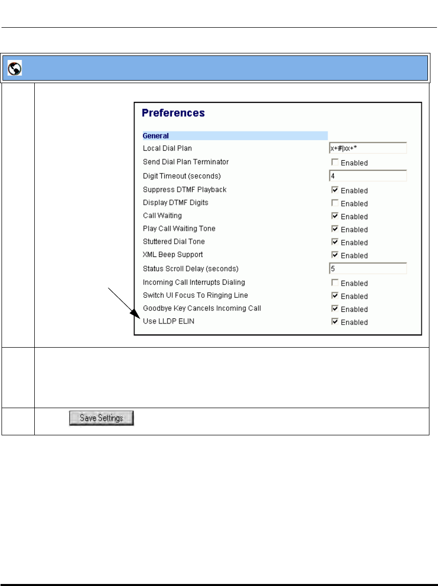
Operational Features
41-001160-03, Rev 00, Releaes 2.4 5-101
Configuring Operational Features
5 Select Basic Settings->Preferences->General.
6 The “Use LLDP ELIN” field is enabled by default. To disable LLDP ELIN, click the check mark in
the box to clear the check mark.
This field enables or disables the use of an Emergency Location Identification Number (ELIN)
received from LLDP as a caller ID for emergency numbers.
7 Click to save your changes.
Aastra Web UI
Use LLDP ELIN
Draft 1
Operational Features
5-102 41-001160-03, Rev 00, Releaes 2.4
IP Phone Administrator Guide
Incoming/Outgoing Intercom with Auto-Answer and Barge In
The Intercom feature allows you to press the configured Intercom button on the IP
phone and then enter the number you want to call to initiate an intercom call.
Intercom calls can be controlled either locally (phone-side) or by the SIP server
(server-side).
You can configure incoming and outgoing intercom calls on all phone models. A
User can configure incoming intercom calls only.
Outgoing Intercom Calls
On outgoing intercom calls, an available unused line is found when the Icom
button is pressed. Since this line has no configuration, the phone applies an
existing configuration ("Outgoing Intercom Settings", Line, default is Line 1) to
this line in preparation for placing the intercom call. For example, an outgoing
intercom call can use the configuration of line 1 but places the actual intercom call
using line 9. Only an Administrator can configure outgoing intercom calls.
A phone-side Intercom call indicates the phone is responsible for telling the
recipient that an intercom call is being placed, while a server-side intercom call
means the SIP server is responsible for informing the recipient. Server-side calls
require additional configuration of a prefix code. After pressing the Icom button
and entering the number to call, the phone automatically adds the prefix to the
called number and sends the outgoing call via the server.
For outgoing intercom calls, an administrator can configure the following
parameters:
Configuration File Parameters Web UI Parameters
• sip intercom type • Type)
• sip intercom prefix code • Prefix Code
• sip intercom line • Line
Note: To configure outgoing intercom calls using these parameters, see
“Configuring Intercom Calls Settings” on page 5-104.
Draft 1

Operational Features
41-001160-03, Rev 00, Releaes 2.4 5-103
Configuring Operational Features
Incoming Intercom Calls
You can configure how the phone handles incoming intercom calls. You can
receive incoming intercom calls whether or not there are active calls on the phone.
The way the phone handles the call depends on the incoming intercom call
configuration. The following paragraphs describe the configuration parameters for
incoming intercom calls.
Microphone Mute
You can mute or unmute the microphone on the IP phone for intercom calls made
by the originating caller. If you want to mute the intercom call, you enable this
feature. If you want to unmute (or hear the intercom call), you disable this feature.
Auto-Answer/Play Warning Tone
The auto-answer feature on the IP phone allows you to enable or disable
automatic answering for an Intercom call. If “Auto-Answer” is enabled, the phone
automatically answers an incoming intercom call. If “Play Warning Tone” is also
enabled, the phone plays a tone to alert the user before answering the intercom
call. If “Auto-Answer” is disabled, the phone rejects the incoming intercom call
and sends a busy signal to the caller.
“Delay” before Auto-Answer
The IP Phones include support for the "delay" parameter (in the Alert-Info header,
used in conjunction with info=alert-autoanswer) in order to facilitate auto-answer
functionality. When present, the value of the "delay" parameter specifies the
length of time in seconds an IP phone rings before a call is auto-answered. If this
value of the "delay" parameter set to 0 (delay=0), then an incoming call is
immediately auto-answered. The absence of the parameter is considered as ring
forever.
In order for the delay functionality to operate, you must first enable Auto-Answer
on the IP Phone.
Draft 1
Operational Features
5-104 41-001160-03, Rev 00, Releaes 2.4
IP Phone Administrator Guide
Allow Barge In
You can configure whether or not the IP phone allows an incoming intercom call
to interrupt an active call. The “sip intercom allow barge in” parameter controls
this feature. When you enable the sip intercom allow barge in parameter
(1 = enable in the configuration files), which is the default value, an incoming
intercom call takes precedence over any active call, by placing the active call on
hold and automatically answering the intercom call. When you disable this
parameter (0 = disable in the configuration files), and there is an active call, the
phone treats an incoming intercom call like a normal call and plays the call
warning tone. You can set this parameter using the configuration files or the
Aastra Web UI.
For incoming intercom calls, an administrator or user can configure the following
parameters:
Configuring Intercom Calls Settings
You can configure the Intercom feature using the configuration files or the Aastra
Web UI.
Configuration File Parameters Web UI Parameters
• sip allow auto answer • Auto-Answer
• sip intercom mute mic • Microphone Mute
• sip intercom warning tone • Play Warning Tone
• sip intercom allow barge in • Barge In
Note: To configure incoming intercom calls using these parameters, see
“Configuring Intercom Calls Settings” on page 5-104.
Note: An administrator can configure the incoming and outgoing
Intercom feature. A user can configure the incoming Intercom feature
only.
Draft 1
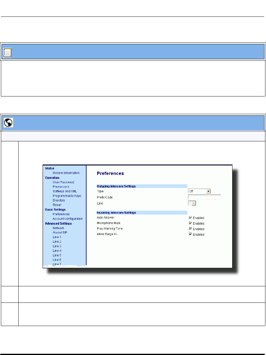
Operational Features
41-001160-03, Rev 00, Releaes 2.4 5-105
Configuring Operational Features
Use the following procedures to configure Intercom calls on the IP phone.
Configuration Files
For specific parameters you can set in the configuration files for outgoing Intercom, see Appendix A, the
section, “Outgoing Intercom Settings” on page A-175.
For specific parameters you can set in the configuration files for incoming Intercom, see Appendix A, the
section, “Incoming Intercom Settings” on page A-177.
Aastra Web UI
Outgoing intercom settings (9480i, 9480i CT, 6755i, 6757i, and 6757i CT only):
1 Click on Basic Settings->Preferences->Outgoing Intercom Settings.
2 Select an Intercom type for outgoing Intercom calls from the Type list box.
Valid values are Phone-Side, Server-Side, Off. Default is Off.
3 If Server-Side is selected, enter a prefix to add to the phone number in the "Prefix Code" field.
Note: For Sylantro servers, enter *96.
Draft 1
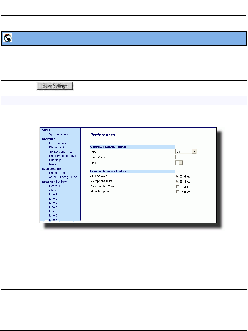
Operational Features
5-106 41-001160-03, Rev 00, Releaes 2.4
IP Phone Administrator Guide
4 If Phone-Side or Server-Side is selected, select a line from the Line list box for which you want the IP
phone to use as its configuration on the Intercom call.
Note: The IP phone uses the configuration from the line you select from this list box. The call itself is
made using the first available line at the time of the call.
5 Click to save your changes.
Incoming intercom settings:
1 Click on Basic Settings->Preferences->Incoming Intercom Settings.
2The "Auto-Answer" field is enabled by default. The automatic answering feature is turned on for the
IP phone for answering Intercom calls. To disable this field, uncheck the box.\
Note: If the Auto-Answer field is not checked (disabled), the phone rejects the incoming intercom call
and sends a busy signal to the caller.
3The "Microphone Mute" field is enabled by default. The microphone is muted on the IP phone for
Intercom calls made by the originating caller. To disable this field, uncheck the box.
4The "Play Warning Tone" field is enabled by default. If “Auto-Answer” is enabled, the phone plays a
warning tone when it receives in incoming intercom call. To disable this field, uncheck the box.
Aastra Web UI
Draft 1
Operational Features
41-001160-03, Rev 00, Releaes 2.4 5-107
Configuring Operational Features
Group Paging RTP Settings
An Administrator or User can configure a specific key (softkey, programmable
key, or expansion module key) on the phone that allows you to send/receive a
Real Time Transport Protocol (RTP) stream to/from pre-configured multicast
address(es) without involving SIP signaling. This is called Group Paging on the IP
phones. You can specify up to 5 listening multicast addresses.
An Administrator can use the following parameters in the configuration files to set
Group Paging RTP Settings:
• paging addr list
• softkeyN type, topsoftkeyN type, prgkeyN type, or expmodX keyN type
•sofkeyN label
• softkeyN value, topsoftkeyN value, prgkeyN value, or expmodX keyN
value
An Administrator or User can use the following parameters in the Aastra Web UI
to set Group Paging RTP Settings:
• Paging Listen Addresses (Path: Basic Settings->Preferences->Group
Paging RTP Settings)
• <Paging> Key (Operation->Softkeys and XML, Programmable Keys, or
Expansion Module Keys)
5The "Allow Barge In" field is enabled by default. If an active line on the phone receives an incoming
intercom call, the active call is put on hold and the phone automatically answers the incoming
intercom call. To disable this field, uncheck the box.
6 Click to save your changes.
Note: The Group Paging RTP Settings are dependant upon the setting for
the “Allow Barge In” parameter.
Aastra Web UI
Draft 1
Operational Features
5-108 41-001160-03, Rev 00, Releaes 2.4
IP Phone Administrator Guide
How it works
After pressing a configured “Paging” key on the phone, the Phone sends RTP to a
preconfigured multicast address(es) (IP port). Any phone in the local network
then listens for RTP on the preconfigured multicast address(es) (IP port). For both
sending and receiving of the multicast RTP there is no sip signaling involved. The
Phone displays the multicast RTP sent/received address(es) to the user.
The phone uses a preconfigured G711 uLaw CODEC for multicast RTP.
For Paging Systems, the phone only plays RTP traffic; users have the ability to
drop a rogue page. The recipient can drop the incoming page if required. The
recipient can also set Do Not Disturb (DND) to ignore any incoming pages.
For incoming RTP multicasts, the ringing display is dependant on the “Allow
Barge-In” parameter. If this parameter is disabled, and there is not other call
on the phone, then the paging is automatically played via the preferred
audio device (see the model-specific IP Phone User Guide for setting
Audio Mode on the phone).
If there is an existing call on the phone, the call initially displays in the ringing
state. The user has the option to accept/ignore the call. If the “Allow Barge-In”
parameter is enabled, the RTP multicast call barges in, and any existing calls are
put on hold.
If an RTP multicast session already exists on the phone, and the phone receives
another incoming RTP multicast session, the priority is given to the first multicast
session and the second multicast session is ignored. The behavior for the
incoming calls in this case is also based on the setting for the “Allow Barge-in”
parameter. The incoming call is handled as if there were an existing call already
on the phone.
Note: Multicast RTP is one way only - from sender to the receiver (i.e.
from sender to the multicast address(es) (receiver)).
Note: For outgoing RTP multicasts, all other existing calls on the phone
are put on hold.
Draft 1
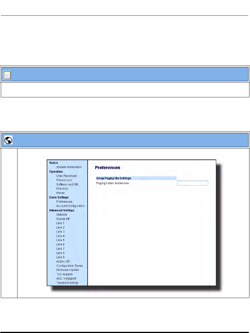
Operational Features
41-001160-03, Rev 00, Releaes 2.4 5-109
Configuring Operational Features
Configuring Group Paging RTP Settings
Use the following procedure to configure Group Paging RTP Settings using the
configuration files.
Use the following procedure to configure RTP streaming for Paging applications
using the Aastra Web UI.
Configuration Files
For specific parameters you can set in the configuration files, see Appendix A, the section, “Group Paging
RTP Settings” on page A-179.
Aastra Web UI
1 Click on Basic Settings->Preferences->Group Paging RTP Settings.
Draft 1
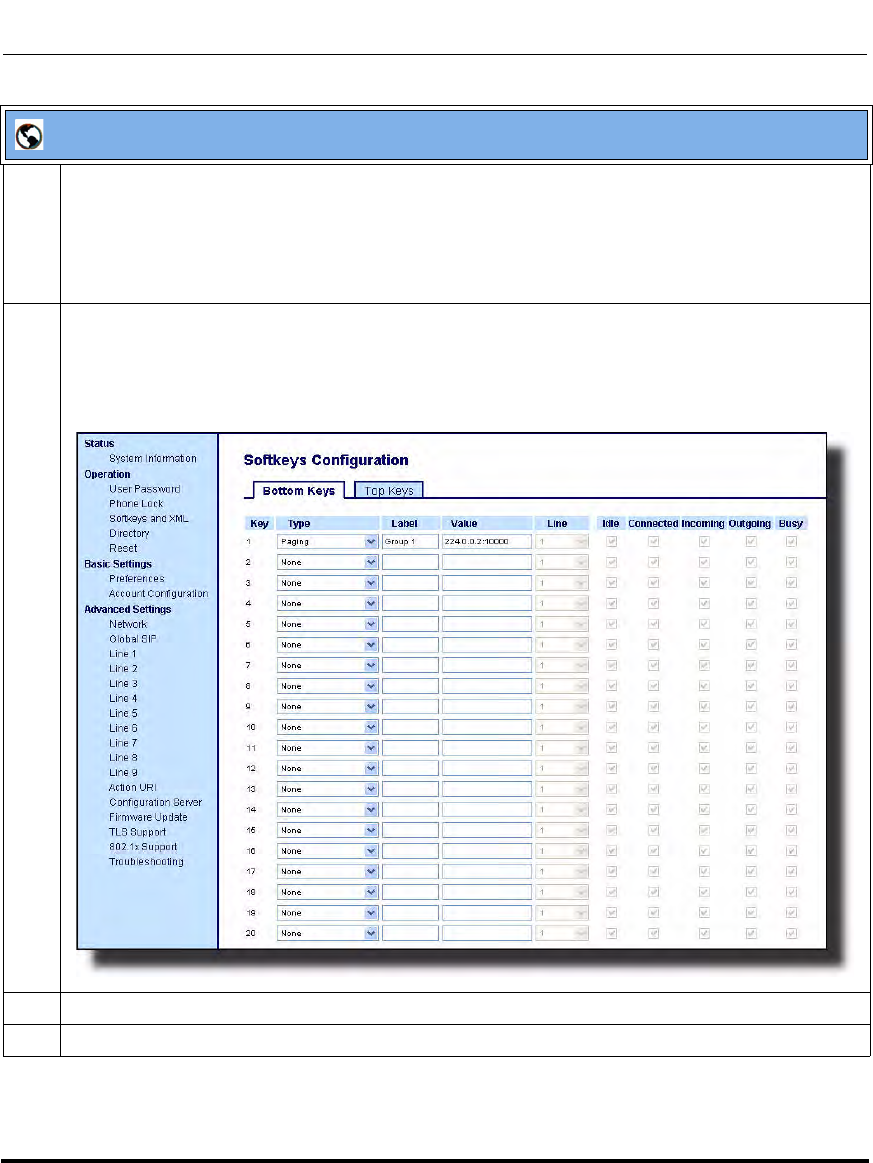
Operational Features
5-110 41-001160-03, Rev 00, Releaes 2.4
IP Phone Administrator Guide
2 In the “Paging Listen Addresses” text box, enter the multicast IP address(es) and port number on
which the phone listens for incoming multicast RTP packets.
Note: Enter the IP address in dotted decimal format (for example,
224.0.0.2:10000,239.0.1.20:15000) If this field is blank, Paging listening capability is disabled on the
phone.
3 Click on Softkeys and XML.
or
Click on Programmable Keys.
or
Click on Expansion Module Keys.
4 Choose a key that you want to assign as the Paging Key and select Paging from the “Type” field.
5 In the “Label” field, enter a key label to assign to the Paging key (for example, “Group 1”).
Aastra Web UI
Draft 1

Operational Features
41-001160-03, Rev 00, Releaes 2.4 5-111
Configuring Operational Features
6 In the “Value” field, enter a multicast IP address(es) and a port number for the Paging key. When you
press this key, the phone initiates an outgoing multicast RTP session to the specified address(es)
using the specified port. (For example, 224.0.0.2:10000).
Note: When you select Paging for the “Type” field, the “Line” field and state fields are disabled.
7 Click to save your changes.
Aastra Web UI
Draft 1
Operational Features
5-112 41-001160-03, Rev 00, Releaes 2.4
IP Phone Administrator Guide
Using the Configured Paging Key on the IP Phone
The following procedure describes the use of the Paging key. The procedures
assumes you have already configured the Paging key using the configuration files
or the Aastra Web UI.
Notes:
1. Recipient of a Paging call can set a global “Do Not Disturb”
(DND) to ignore any incoming pages.
2. For incoming Paging, the phones use the Intercom configuration
settings. The incoming Page is dependant on the “Allow Barge-In”
parameter setting and the “Idling/On Call” state.
Aastra IP Phone UI
Step Action
On the IP Phone, press the key you configured for Paging (labeled as “Group 1” in the following
illustration).
The phone opens a multicast RTP session and an outgoing OR incoming phone screen displays as
follows:
Press the Drop key to end the multicast RTP session and return to the idle screen.
Note: If you enable global DND on the phone, the incoming multicast RTP session is dropped.
Tues Jan1 10:00am
Services
Dir
Callers
Icom
Group 1
LAB
ACD
Paging
Drop
00:01
Draft 1

Operational Features
41-001160-03, Rev 00, Releaes 2.4 5-113
Configuring Operational Features
Key Mapping
There are hard keys on your phone, such as Hold, Redial, Xfer, and Conf that are
configured by default for specific call-handling features. (See the product-specific
User Guide for more information about these key functions.
Enabling/Disabling Redial, Xfer, and Conf Keys
You can enable or disable the Redial, Xfer, and Conf keys as required using the
following parameters in the configuration files:
• redial disabled
• conference disabled
• call transfer disabled
Valid values for this parameter are 0 (enabled) and 1 (disabled).
If this parameter is set to 1, the key is not active and is ignored if pressed by the
user. For "redial disabled" the value of 1 does not save the dialed number to the
"Redial List".
If this parameter is set to 0, the key is active and can be pressed by the user.
This feature is configurable via the configuration files only.
Notes:
1. On the 9480i, 9480i CT, 6755i, 6757i, and 6757i CT the Xfer and
Conf keys are hard-coded by default on keys 5 and 6 to the left of the
LCD display and cannot be reassigned. The Xfer and Conf labels
display when you lift the handset. To disable these keys, see the
next paragraph.
2. On the 9143i, 6751i, and 6753i, the Xfer and Conf keys are
assigned by
default to keys 5 and 6, respectively. These keys are programmable
keys and can be reassigned if applicable. To disable these keys, see
the next paragraph.
Draft 1
Operational Features
5-114 41-001160-03, Rev 00, Releaes 2.4
IP Phone Administrator Guide
Use the following procedure to enable/disable the Redial, Xfer, and Conf keys.
Mapping Redial and Conf Keys as Speeddials
You can map the Redial and Conference keys on the IP phone to use as speeddial
keys. When the Redial or Conference key is pressed, the number configured for
the key automatically speed dials. If no number is configured, the Redial and
Conference keys return to their original functionality.
You can configure this feature using the configuration files or the Aastra Web UI.
Use the following procedures to set the Redial and Conf keys as speeddial keys.
Configuration Files
For specific parameters you can set in the configuration files, see Appendix A, the section, “Mapping Key
Settings” on page A-189.
Note: If you configure the Redial and Conference keys for speeddialing
on the 6757i CT Base Station, the Redial and Conference keys on the
6757i CT handset retain their original functionality. The Redial and
Conference keys on the handset are not configured for speeddial.
Configuration Files
For specific parameters you can set in the configuration files, see Appendix A, the section, “Mapping Key
Settings” on page A-189.
Draft 1
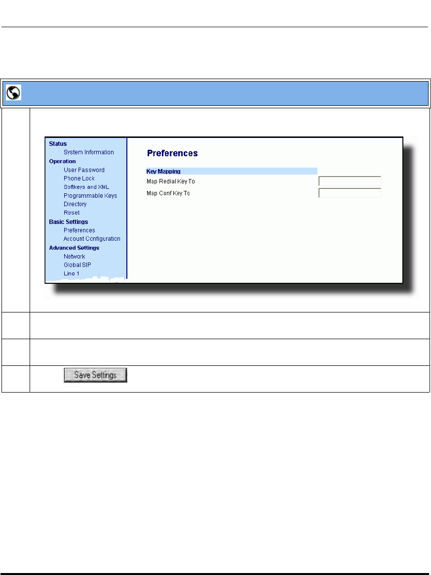
Operational Features
41-001160-03, Rev 00, Releaes 2.4 5-115
Configuring Operational Features
Aastra Web UI
1 Click on Basic Settings->Preferences.
2 In the Key Mapping section, enter a number in the "Map Redial Key To" field, that the IP phone will
use to speeddial when the Redial key is pressed.
3 Enter a number in the "Map Conf Key To" field, that the IP phone will use to speeddial when the
Conf Key is pressed.
4 Click to save your changes.
Draft 1
Operational Features
5-116 41-001160-03, Rev 00, Releaes 2.4
IP Phone Administrator Guide
Using Redial Key for “Last Number Redial”
The IP phones have an enhanced redial user interface that allows a user to
quickly redial the last number that was dialed out from the phone. You can:
• Press the REDIAL key twice to redial the last number dialed.
• Press the REDIAL key once, scroll the list of numbers, then press the
REDIAL button again to dial the number that displays on the screen.
The “last number redial” feature for the Redial key is static and is not
configurable.
Note: You can use the Redial key during active calls.
Draft 1

Operational Features
41-001160-03, Rev 00, Releaes 2.4 5-117
Configuring Operational Features
Ring Tones and Tone Sets
You can configure ring tones and ring tone sets on the IP phones.
Ring Tones
There are several distinct ring tones a user or administrator can select from to set
on the IP phones. You can enable/disable these ring tones on a global basis or on a
per-line basis.
The following table identifies the valid settings and default values for each type of
configuration method.
Ring Tone Settings Table
Configuration Method Valid Values Default Value
Configuration Files Global:
0 (Tone1)
1 (Tone 2)
2 (Tone 3)
3 (Tone 4)
4 (Tone 5)
5 (Silent)
Per-Line:
-1 (global)
0 (Tone1)
1 (Tone 2)
2 (Tone 3)
3 (Tone 4)
4 (Tone 5)
5 (Silent)
Global:
0 (tone 1)
Per-Line:
-1 (global)
IP Phone UI Global:
Tone 1
Tone 2
Tone 3
Tone 4
Tone 5
Global:
Tone 1
Draft 1

Operational Features
5-118 41-001160-03, Rev 00, Releaes 2.4
IP Phone Administrator Guide
Configuration Method Valid Values Default Value
Aastra Web UI Global:
Tone 1
Tone 2
Tone 3
Tone 4
Tone 5
Silent
Per-Line:
Global
Tone 1
Tone 2
Tone 3
Tone 4
Tone 5
Silent
Global:
Tone 1
Per-Line:
Global
Draft 1

Operational Features
41-001160-03, Rev 00, Releaes 2.4 5-119
Configuring Operational Features
Ring Tone Sets
In addition to ring tones, you can configure ring tone sets on a global-basis on the
IP phones. Ring tone sets consist of tones customized for a specific country. The
ring tone sets you can configure on the IP phones are:
•US (Default - also used in Canada)
• Australia
• Europe (generic tones)
•France
•Germany
•Italy
•Mexico
• United Kingdom (UK)
When you configure the country's tone set, the country-specific tone is heard on
the phone for the following:
- dial tone
- secondary dial tone
- ring tone
- busy tone
- congestion tones
- call waiting tone
- ring cadence pattern
Important: You configure ring tones and tone sets using the Aastra Web UI, IP Phone UI, or configuration
files. However, when using the IP phone UI, you can set global configuration only.
Draft 1
Operational Features
5-120 41-001160-03, Rev 00, Releaes 2.4
IP Phone Administrator Guide
Configuring Ring Tones and Tone Sets
Use the following procedures to configure ring tones and tone sets on the IP
phones.
Configuration Files
For specific parameters you can set in the configuration files for ring tones, see Appendix A, the section,
“Ring Tone and Tone Set Global Settings” on page A-143 or “Ring Tone Per-Line Settings” on page A-145.
IP Phone UI
Step Action
For global configuration only:
1 Press on the phone to enter the Options List.
2Select Preferences.
3Select Tones.
4Select Set Ring Tone.
5 Select the type of ring tone (Tone 1 through Tone 5, or Silent).
6 Press Done to save the change.
7Select Tone Set.
8 Select the country for which you want to apply the tone set.
Valid values are Australia, Europe, France, Germany, Italy, Mexico, UK, and US. Default is US.
9 Press Done to save the change.
The ring tone and tone set you select is immediately applied to the IP phone.
Draft 1
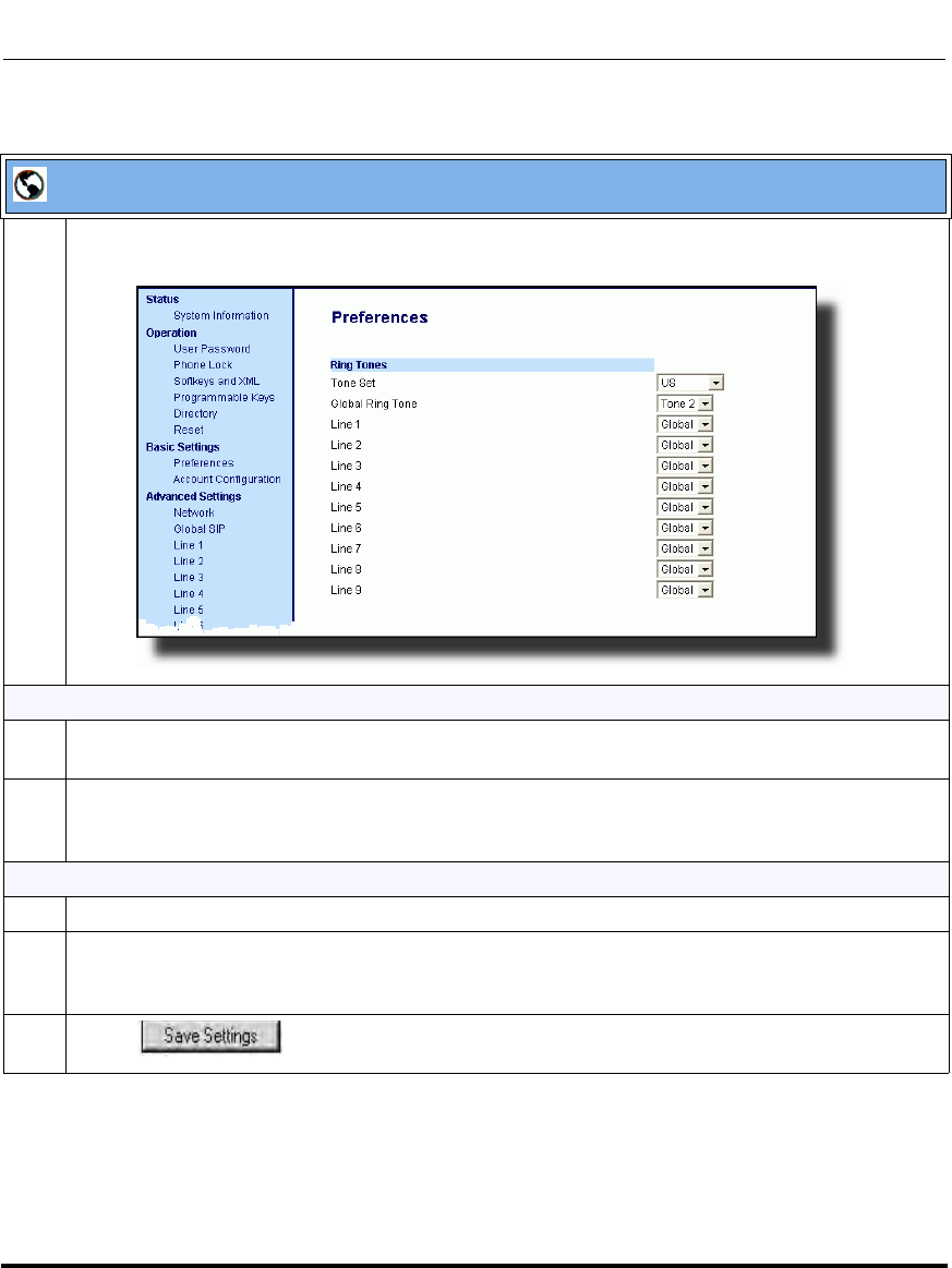
Operational Features
41-001160-03, Rev 00, Releaes 2.4 5-121
Configuring Operational Features
Aastra Web UI
1 Click on Basic Settings->Preferences.
For global configuration:
2 In the "Ring Tones" section, select a country from the "Tone Set" field.
Valid values are Australia, Europe, France, Germany, Italy, Mexico, UK, and US. Default is US.
3 Select a value from the "Global Ring Tone" field.
Note: See the “Ring Tone Settings Table” on page 5-117 for valid values.
For per-line configuration:
4 In the "Ring Tone" section, select a line for which you want to set ring tone.
5 Select a value from the "LineN" field.
Note: See the “Ring Tone Settings Table” on page 5-117 for valid values.
6 Click to save your changes.
Draft 1

Operational Features
5-122 41-001160-03, Rev 00, Releaes 2.4
IP Phone Administrator Guide
Priority Alerting
Priority alerting on the IP phones is a feature that allows incoming calls to trigger
pre-defined ringing or call waiting alert tones.
You can enable or disable priority alerting on the IP phone for the Asterisk,
Broadworks, and Sylantro servers using the configuration files and the Aastra
Web UI. Configuration of priority alerting is on a global-basis only.
How Priority Alerting Works
When the IP phone detects an incoming call, the phone firmware inspects the
INVITE request in the IP packet for an "Alert-Info" header.
If it contains an "Alert-Info" header, the firmware strips out the URL and keyword
parameter and maps it to the appropriate Bellcore tone.
If there is no keyword parameter in the "Alert-Info" header, or the INVITE
message contains no "Alert-Info" header, then the IP phone firmware uses the
Bellcore standard ring tone.
Asterisk/Broadworks Servers
The ring tone keywords that can display in the "Alert-Info" header for an Asterisk
and Broadworks server are:
When the ring tone keywords appear in an "Alert-Info" header from an Asterisk or
Broadworks server, the IP phone maps the keywords to the default ring tone
patterns.
Asterisk/Broadworks Server
Ring Tone Keywords
Bellcore-dr2
Bellcore-dr3
Bellcore-dr4
Bellcore-dr5
Draft 1

Operational Features
41-001160-03, Rev 00, Releaes 2.4 5-123
Configuring Operational Features
Sylantro Servers
The ring tone keywords that can display in the "Alert-Info" header for a Sylantro
server are:
When the ring tone keywords appear in an "Alert-Info" header from a Sylantro
server, the keyword is mapped to the ring tone pattern based on the configuration
you set in the Aastra Web UI or the configuration files.
Ring Tone Patterns
In IP Telephony, different ringing patterns have different frequencies and
cadences. Ring cadence is the ringing pattern heard by the called party, before
they pick up the call.
On the IP phones, if you enable priority alerting when using an Asterisk or
Broadworks server, the IP phone uses the following Bellcore-specified tones by
default:
Ring Tone Pattern (Asterisk/Broadworks Servers)
Sylantro Server
Ring Tone Keywords
alert-acd (auto call distribution)
alert-community-1
alert-community-2
alert-community-3
alert-community-4
alert-emergency
alert-external
alert-group
alert-internal
alert-priority
Call Criteria Bellcore Tones
internal calls Bellcore-dr2
external calls Bellcore-dr3
calls with contact list Bellcore-dr4
calls with specific time frames Bellcore-dr5
Draft 1

Operational Features
5-124 41-001160-03, Rev 00, Releaes 2.4
IP Phone Administrator Guide
If you enable priority alerting when using a Sylantro server, you can specify the
Bellcore tone to be used for the following configurable criteria:
Ring Tone Pattern (Sylantro Servers)
A System Administrator can configure the ring tone cadences if required, using
the configuration files. The following table identifies the different Bellcore ring
tone patterns and cadences.
Call criteria Bellcore tones for each call criteria
alert-acd (auto call distribution)
alert-community-1
alert-community-2
alert-community-3
alert-community-4
alert-emergency
alert-external
alert-group
alert-internal
alert-priority
Normal ringing (default)
Bellcore-dr2
Bellcore-dr3
Bellcore-dr4
Bellcore-dr5
Silent
Bellcore Tone Pattern
ID Pattern Cadence
Minimum
Duration
(ms)
Nominal
Duration
(ms)
Maximum
Duration
(ms)
(Standard) 1 Ringing
Silent 2s On
4s Off 1800
3600 2000
4000 2200
4400
Bellcore-dr2 2 Ringing
Silent
Ringing
Silent
Long
Long
Long
630
315
630
3475
800
400
800
4000
1025
525
1025
4400
Bellcore-dr3 3 Ringing
Silent
Ringing
Silent
Ringing
Silent
Short
Short
Long
315
145
315
145
630
2975
400
200
400
200
800
4000
525
525
525
525
1025
4400
Bellcore-dr4 4 Ringing
Silent
Ringing
Silent
Ringing
Silent
Short
Long
Short
200
145
800
145
200
2975
300
200
1000
200
300
4000
525
525
1100
525
525
4400
Bellcore-dr5 5 Ringing 450 500 550
Draft 1

Operational Features
41-001160-03, Rev 00, Releaes 2.4 5-125
Configuring Operational Features
Note: If the "Do Not Disturb" (DND) or the "Call Forward" (CFWD)
feature is enabled on the server-side, and the user is still waiting for a call,
the "Bellcore-dr5" is a ring splash tone that reminds the user that these are
enabled.
Draft 1
Operational Features
5-126 41-001160-03, Rev 00, Releaes 2.4
IP Phone Administrator Guide
Configuring Priority Alerting and Ring Tone Cadences using the
Configuration Files
Use the following procedures to configure priority alerting and ring tone cadences
on the IP phones.
Configuration Files
For specific parameters you can set in the configuration files, see Appendix A, the sections,
•“Priority Alert Settings” on page A-155.
•“Bellcore Cadence Settings” on page A-160.
Note: You can configure Bellcore cadences using the configuration files
only.
Draft 1
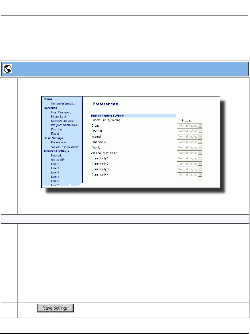
Operational Features
41-001160-03, Rev 00, Releaes 2.4 5-127
Configuring Operational Features
Configuring Priority Alerting using the Aastra Web UI.
Use the following procedure to configure Priority Alerting using the Aastra Web
UI.
Aastra Web UI
1 Click on Basic Settings->Preferences.
2 In the "Priority Alerting Settings" section, enable the "Enable Priority Alerting" field by checking the
check box. (Disable this field by unchecking the box).
For Sylantro Servers:
3 Select a ring tone pattern for each of the following fields:
•Group
• Internal
• External
• Emergency
•Priority
• auto call distribution
• community-1
• community-2
• community-3
• community-4
4 Click to save your changes.
Draft 1

Operational Features
5-128 41-001160-03, Rev 00, Releaes 2.4
IP Phone Administrator Guide
Call Waiting Tones
Call Waiting is a feature that tells you if a new caller is trying to contact you when
you are already on the phone. A discreet tone alerts you to the new caller, so you
can answer your second incoming call by putting your first caller on hold.
The IP phones use the following Bellcore-specified call waiting tones.
For Asterisk and Broadworks servers, call waiting tones are specified by the
default Bellcore tones indicated in the table Ring Tone Pattern (Asterisk/
Broadworks Servers) on page -123.
For Sylantro servers, call waiting tones are specified by the Bellcore tones you
configure in the Aastra Web UI or the configuration files. See the table Ring Tone
Pattern (Sylantro Servers) on page -124.
Reference
For more information about enable/disabling call waiting on the IP Phone, see the
section, “Call Waiting/Call Waiting Tone” on page 5-67.
Bellcore
Call-Waiting Tone Pattern
ID Pattern
Minimum
Duration
(ms)
Nominal
Duration
(ms)
Maximum
Duration
(ms)
CallWaitingTone 1 1 Tone On 270 300 330
Bellcore-dr2
CallWaitingTone2 2 Tone On
Tone Off 90
90 100
100 110
110
Bellcore-dr3
CallWaitingTone3 3 Tone On
Tone Off
Tone On
Tone Off
90
90
90
90
100
100
100
100
110
110
110
110
Bellcore-dr4
CallWaitingTone4 4 Tone On
Tone Off
Tone On
Tone Off
90
90
270
90
100
100
300
100
110
110
330
110
Draft 1

Operational Features
41-001160-03, Rev 00, Releaes 2.4 5-129
Configuring Operational Features
Directed Call Pickup (BLF or XML Call Interception)
Directed call pickup is a feature on the phones that allows a user to intercept a call
on a ringing phone which is part of the same interception group. You can use the
Directed call pickup feature on the phone in two ways:
• With the existing BLF feature on Asterisk, a user can dial “*76” followed by
the extension to pick up a ringing call on another phone. (For more
information about BLF, see “Busy Lamp Field (BLF)” on page -169
• Using XML, a user can intercept a call by selecting an extension from a list
and then pressing a “Pickup” softkey/programmable key. To use the Directed
call pickup feature from an XML application, you must list all ringing
extensions using the AastraIPPhoneTextMenu XML object in an XML
script. This allows the user to select the ringing extension from a text menu
without having to dial. The following illustration shows an example of how
this feature displays to the LCD from an XML application.:
(For more information about using the AastraIPPhoneTextMenu object, see
Appendix F, the section, “Text Menu Object (Menu Screens)” on page F-6.
Ringing Extensions
201
212
225
234
Pickup
Done
Draft 1
Operational Features
5-130 41-001160-03, Rev 00, Releaes 2.4
IP Phone Administrator Guide
BLF and XML softkeys/programmable keys monitor the states of an extension.
The extension states can be one of three states: "busy", "ringing" and "idle". If the
monitored extension is in the "ringing" state with an incoming call, and "Directed
call pickup" is enabled, pressing the BLF or XML key can pick up the incoming
call on the monitored extension.
Directed Call Pickup Prefix (optional)
The optional “directed call pickup prefix” allows you to enter a specific prefix
string (depending on what is available on your server), that the phone
automatically dials when dialing the Directed Call Pickup number. For example,
for Broadsoft servers, you can enter a value of *98 for the “directed call pickup
prefix”. When the phone performs the Directed Call Pickup after pressing a BLF
or BLF/List softkey, the phone prepends the *98 value to the designated extension
of the BLF or BLF/List softkey when dialing out.
How this feature works when Directed Call Pickup is enabled with BLF or
BLF/List
1. Phone A monitors Phone B via BLF/List.
2. Phone C calls Phone B; Phone B rings.
3. If you press the BLF/List softkey on Phone A, it picks up the ringing line on
Phone B.
4. Phone C connects to Phone A.
How this feature works when Directed Call Pickup is disabled with BLF or
BLF/List
1. Phone A monitors Phone B via BLF/List.
2. Phone C calls Phone B; Phone B rings.
3. If you press the BLF/List softkey on Phone A, it performs a speeddial to
Phone B.
4. Phone C and Phone A are ringing Phone B on separate lines (if available).
Note: The Asterisk and Epygi Quadro 4x/16x IP PBX servers support
this feature. For details about Asterisk support, contact Aastra Technical
Support.
Draft 1
Operational Features
41-001160-03, Rev 00, Releaes 2.4 5-131
Configuring Operational Features
You can enable/disable “Directed Call Pickup” using the configuration files or the
Aastra Web UI.
Notes:
1. The default method for the phone to use is Directed Call Pickup over
BLF if the server provides applicable information. If the Directed Call
Pickup over BLF information is missing in the messages to the server, the
Directed Call Pickup by Prefix method is used if a value for the prefix
code exists in the configuration.
2. You can define only one prefix at a time for the entire BLF/List.
3. The phone that picks up displays the prefix code + the extension
number (for example, *981234 where prefix key = *98, extension =
1234).
Note: The “Directed Call Pickup” feature is disabled by default.
Draft 1
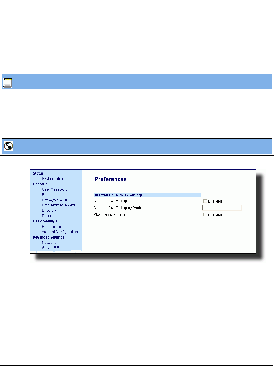
Operational Features
5-132 41-001160-03, Rev 00, Releaes 2.4
IP Phone Administrator Guide
Enabling/Disabling Directed Call Pickup
Use the following procedure to enable or disable the Directed Call Pickup feature
on the IP phone.
Configuration Files
To enable/disable Directed Call Pickup on the IP phone using the configuration files, see Appendix A, the
section, “Directed Call Pickup (BLF or XML Call Interception) Settings” on page A-184.
Aastra Web UI
1 Click on Basic Settings->Preferences->Directed Call Pickup Settings.
2 Enable the "Directed Call Pickup" field by checking the check box.
(Disable this field by unchecking the box). Default is disabled.)
3 (optional) Enter a prefix in the "Directed Call Pickup Prefix" field. For example, *98.
This prefix is appended to the beginning of the Directed Call Pickup number when dialed from the
BLF or BLF/List softkey.
Draft 1
Operational Features
41-001160-03, Rev 00, Releaes 2.4 5-133
Configuring Operational Features
Configuring BLF/BLF List for Directed Call Pickup
Use the following procedure to configure BLF/BLF List for Directed Call Pickup
in the configuration files.
4 Enable the "Play a Ring Splash" field by checking the check box.
(Disable this field by unchecking the box). Default is disabled.)
The IP phone plays a short "ring splash" when there is an incoming call on the BLF monitored
extension. If the "Play a Ring Splash" parameter is enabled, and the host tone is idle, the tone plays
a "ring splash".
5 Click to save your changes.
Note: You must enable Directed Call Pickup before performing these
procedures. See “Enabling/Disabling Directed Call Pickup” on
page 5-132.
Configuration Files
To set BLF or BLF\List in the configuration files for Directed Call Pickup, see Appendix A, the sections:
•“Softkey/Programmable Key/Feature Key/Expansion Module Key Parameters” on page A-192.
•“BLF List URI Settings” on page A-230.
Aastra Web UI
Draft 1
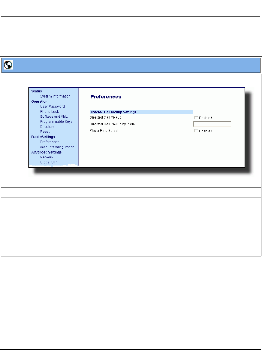
Operational Features
5-134 41-001160-03, Rev 00, Releaes 2.4
IP Phone Administrator Guide
Use the following procedure to configure BLF or BLF/List for Directed Call
Pickup in the Aastra Web UI.
Aastra Web UI
1 Click on Basic Settings->Preferences->Directed Call Pickup Settings.
2 Enable the "Directed Call Pickup" field by checking the check box.
3 (optional) Enter a prefix in the "Directed Call Pickup Prefix" field. For example, *98.
This prefix is appended to the beginning of the Directed Call Pickup number when dialed from the
BLF or BLF/List softkey.
4 Enable the "Play a Ring Splash" field by checking the check box.
The IP phone plays a short "ring splash" when there is an incoming call on the BLF monitored
extension. If the "Play a Ring Splash" parameter is enabled, and the host tone is idle, the tone plays
a "ring splash".
Draft 1
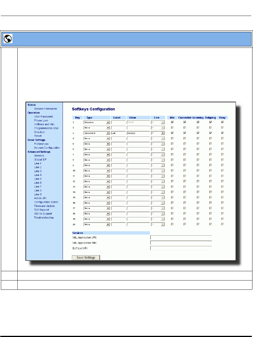
Operational Features
41-001160-03, Rev 00, Releaes 2.4 5-135
Configuring Operational Features
5 Click on Operation->Softkeys and XML
or
Click on Operation->Programmable Keys
or
Click on Operation->Expansion Module <N>.
Note: Depending on your phone-model, the key configuration screen displays. The 6757i Key
Screen is shown as an example.
6 Select a softkey or programmable key to configure.
7 In the "Type" field, select "BLF" (Asterisk), "BLF\List" (BroadSoft BroadWorks).
Aastra Web UI
Draft 1
Operational Features
5-136 41-001160-03, Rev 00, Releaes 2.4
IP Phone Administrator Guide
8For the 9480i, 9480i CT, 6755i, 6757i, and 6757i CT softkeys:
In the "Label" field, enter the name of the person who’s extension you are monitoring (if “Type” is
BLF).
Note: If BLF\List type is selected, no label value is required. The BroadWorks BLF List name is
configured in the "BLF List URI" field instead.
9 In the "Value" field, enter a value to associate with the softkey or programmable key.
For example, for BLF, the value is the extension you want to monitor.
For BLF\List, the value is an identifier for the list of numbers you are monitoring.
10 Click to save your changes.
11 In the "Line" field, select a line number that is actively registered to the appropriate SIP proxy you are
using.
12 In the "BLF List URI" field, enter the name of the BLF list defined on the BroadSoft BroadWorks
Busy Lamp field page for your particular user.
For example, my6757i-blf-list@as.broadworks.com.
Note: The value of the BLF\List URI parameter must match the list name configured. Otherwise, no
values display on the 6757i screen and the feature is disabled.
13 Select the line state (idle, connected, incoming, outgoing, busy) that you want to apply to the BLF
softkey or programmable key.
14 Click to save your changes.
Aastra Web UI
Draft 1
Operational Features
41-001160-03, Rev 00, Releaes 2.4 5-137
Configuring Operational Features
Configuring XML for Directed Call Pickup
Use the following procedure to configure XML for Directed Call Pickup in the
configuration files.
Notes:
1. Before implementing this procedure, you must create an XML
application that the phone uses when the XML softkey or programmable
key is pressed. This XML application must be entered as a URI in the
“Value” field of the XML key. For information about creating an XML
script, see Appendix F, the section, “Text Menu Object (Menu Screens)”
on page F-6.
2. You must enable Directed Call Pickup before performing these
procedures. See “Enabling/Disabling Directed Call Pickup” on
page 5-132.
Configuration Files
To set XML in the configuration files for Directed Call Pickup, see Appendix A, the section, “Softkey/
Programmable Key/Feature Key/Expansion Module Key Parameters” on page A-192.
Draft 1

Operational Features
5-138 41-001160-03, Rev 00, Releaes 2.4
IP Phone Administrator Guide
Use the following procedure to configure XML for Directed Call Pickup in the
Aastra Web UI.
Aastra Web UI
1 Click on Basic Settings->Preferences->Directed Call Pickup Settings.
2 Enable the "Directed Call Pickup" field by checking the check box.
3 (optional) Enter a prefix in the "Directed Call Pickup Prefix" field. For example, *98.
This prefix is appended to the beginning of the Directed Call Pickup number when dialed from the
BLF or BLF/List softkey.
4 Enable the "Play a Ring Splash" field by checking the check box.
The IP phone plays a short "call waiting tone" when there is an incoming call on the BLF monitored
extension. If the "Play a Ring Splash" parameter is enabled, and the host tone is idle, the tone plays
a "ring splash".
Draft 1
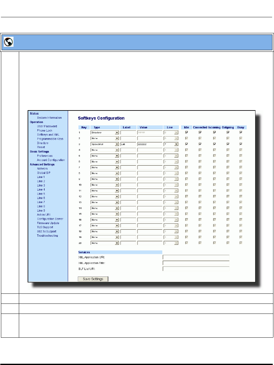
Operational Features
41-001160-03, Rev 00, Releaes 2.4 5-139
Configuring Operational Features
5 Click on Operation->Softkeys and XML
or
Click on Operation->Programmable Keys
or
Click on Operation->Expansion Module <N>.
Note: Depending on your phone-model, the key configuration screen displays. The 6757i Key
Screen is shown as an example.
6 Select a softkey or programmable key to configure.
7 In the "Type" field, select "XML”.
8For the 9480i, 9480i CT, 6755i, 6757i, and 6757i CT softkeys:
In the "Label" field, enter the name of the person who’s extension you are monitoring.
Aastra Web UI
Draft 1
Operational Features
5-140 41-001160-03, Rev 00, Releaes 2.4
IP Phone Administrator Guide
9 In the "Value" field, enter the URI that the phone uses to display the XML application to the LCD.
For example, http://65.205.71.13/xml/startup/key.php?user=$$SIPREMOTENUMBER$$.
Note: For more information about creating an XML script to use with Directed Call Pickup, see
Appendix F, the section, “Text Menu Object (Menu Screens)” on page F-6.
10 Select the line state (idle, connected, incoming, outgoing, busy) that you want to apply to the XML
softkey or programmable key.
11 Click to save your changes.
Aastra Web UI
Draft 1
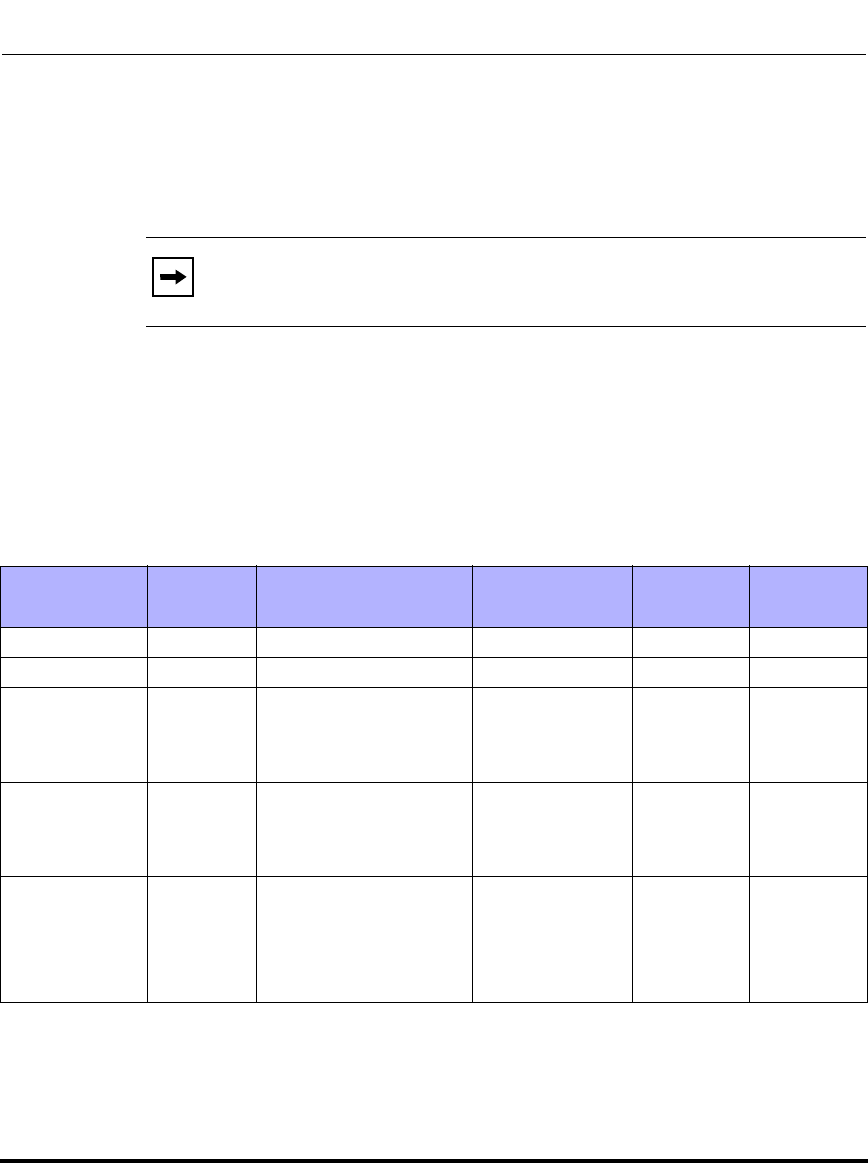
Operational Features
41-001160-03, Rev 00, Releaes 2.4 5-141
Configuring Operational Features
Softkeys/Programmable Keys/Feature Keys/Expansion Module Keys
You can configure the softkeys, programmable keys (9143i and 6753i have
programmable keys only), feature keys, and expansion module keys to perform
specific functions on the IP phones.
Softkeys (9480i, 9480i CT, 6755i, 6757i, 6757i CT)
The 9480i, 9480i CT, and 6755i IP phone have 6 softkeys you can configure to
perform specific functions, The 6757i and 6757i CT IP phones have 12 softkeys
you can configure. With up to 3 expansion modules attached to a 67xi model
phone, you can get an additional 108 softkeys (M670i) or an additional 180
softkeys (M675i) to configure. The following table provides the number of
softkeys you can configure, and the number of lines available for each type of
phone.
*The M670i expansion module consists of 36 softkeys. You can have up to 3 expansion modules on an IP
phone totaling 108 softkeys. Valid for all 67xi model phones EXCEPT the 6751i.
**The M675i expansion module consists of 60 softkeys. You can have up to 3 expansion modules on an IP
phone totaling 180 softkeys. Valid for 6755i, 6757i, and 6757i CT phones.
Note: When entering definitions for softkeys in the configuration files,
the “#” sign must be enclosed in quotes.
IP Phone
Model Softkeys Expansion Module
Keys Programmable
Keys Lines
Available
Handset
Keys
Available
9480i 6 Not Applicable - 9-
9480i CT 6 Not Applicable - 915
6755i 6 36 to 108*
(Model M670i)
60 to 180**
(Model M675i)
69-
6757i 12 36 to 108*
(Model M670i)
60 to 180**
(Model M675i)
-9-
6757i CT 12 36 to 108* on Base
Station
(Model M670i)
60 to 180** on Base
Station
(Model M675i)
-915
Draft 1

Operational Features
5-142 41-001160-03, Rev 00, Releaes 2.4
IP Phone Administrator Guide
State-Based Softkeys (9480i, 9480i CT, 6755i, 6757i, 6757i CT only)
Users and administrators can configure a specific state to display when a softkey
is being used. Available states you can configure for each softkey include:
•idle - The phone is not being used.
•connected - The current line is in an active call (or the call is on hold)
•incoming - The phone is ringing.
•outgoing - The user is dialing a number, or the far-end is ringing.
•busy - The current line is busy because the line is in use or the line is set as
“Do Not Disturb”.
The following table identifies the applicable default states for each type of
softkey you can configure on the IP phone.
Softkey Type Default States
None All states disabled.
Line idle, connected, incoming, outgoing, busy
Speeddial idle, connected, incoming, outgoing, busy
DND idle, connected, incoming, outgoing, busy
BLF idle, connected, incoming, outgoing, busy
BLF List idle, connected, incoming, outgoing, busy
Auto Call
Distribution
(ACD)
idle
Directed Call
Pickup (DCP)
Group Call
Pickup (GCP)
idle, connected, incoming, outgoing, busy
XML idle, connected, incoming, outgoing, busy
WebApps idle, connected, incoming, outgoing, busy
Flash All states disabled.
Sprecode connected
Park connected
Pickup idle, outgoing
Draft 1
Operational Features
41-001160-03, Rev 00, Releaes 2.4 5-143
Configuring Operational Features
You can enable or disable the softkey states using the configuration files or the
Aastra Web UI. In the Aastra Web UI, you disable a state by unchecking the box
for that operational state.
In the configuration files, you use the following parameters to enable and disable
operational states:
• softkeyN states
You can enter multiple values (idle, connected, incoming, outgoing, busy) for
the "softkeyN state" parameter. For example:
softkeyN states: idle connected
You must associate the softkeyN state parameter with a specific softkey. In the
following example, the softkeyN states parameter is associated with softkey 12:
Last Call Return idle, connected, incoming, outgoing, busy
Call Forward idle, connected, incoming, outgoing, busy
BLF/Xfer idle, connected, incoming, outgoing, busy
Speeddial/Xfer idle, connected, incoming, outgoing, busy
Directory idle, connected, incoming, outgoing, busy
Callers List idle, connected, incoming, outgoing, busy
Intercom idle, connected, incoming, outgoing, busy
Services idle, connected, incoming, outgoing, busy
Phone Lock All states disabled.
Paging All states disabled.
Empty idle, connected, incoming, outgoing, busy
Softkey Type Default States
Draft 1

Operational Features
5-144 41-001160-03, Rev 00, Releaes 2.4
IP Phone Administrator Guide
softkey12 type: speeddial
softkey12 label: voicemail
softkey12 value *89
softkey12 states: outgoing
Note: The IP phone idle screen condenses the softkeys. So in the
previous example, softkey 12 will appear in position 1 if no other
softkeys are set. A softkey type of "empty" does not display on the idle
screen at all. For more information about the softkey type of "empty" see
Appendix A, the section, “Softkey Settings for 9480i, 9480i CT, 6755i,
6757i, 6757i CT” on page A-193.
Draft 1
Operational Features
41-001160-03, Rev 00, Releaes 2.4 5-145
Configuring Operational Features
Configuration Example
The following example illustrates the use of the "softkeyN states" parameter, and
the "softkeyN type" parameter with a value of empty. For clarity purposes, only
the "softkeyN type" and "softkeyNstates" parameters are shown.
softkey1 type: line
softkey1 states: idle connected
softkey3 type: dnd
softkey3 states: idle
softkey4 type: line
softkey5 type: empty
softkey5 states: connected
softkey6 type: speeddial
softkey6 states: connected
The following table shows how the keys in the example above would display on
the IP Phone UI.
Softkeys and programmable keys are configurable using the Aastra Web UI or the
configuration files.
Note: The "empty" key type allows a softkey to be removed quickly by
deleting the softkey information from the configuration file.
Softkey Idle Connected Notes
softkey1 Key 1 Key 2 Line displays for softkey1.
Key 1 in connected state is the Drop key. Idle
and connected display as applicable.
softkey2 (not used) (not used) Softkey2 is not displayed.
softkey3 Key 2 (not used) DND displays for softkey3. Idle displays as
applicable.
softkey4 Key 3 Key 3 Line displays for softkey4. Default state
values (idle, connected, incoming, outgoing)
display as applicable.
softkey5 (not used) Key 4 (blank) A blank displays for softkey5. Connected
displays as applicable.
softkey6 (not used) Key 5 Speeddial displays for softkey6. Connected
displays as applicable.
Draft 1
Operational Features
5-146 41-001160-03, Rev 00, Releaes 2.4
IP Phone Administrator Guide
Programmable Keys (9143i, 6753i, 6755i)
The following table provides the number of softkeys and programmable keys you
can configure, and the number of lines available for each type of phone.
*The M670i expansion module consists of 36 softkeys. You can have up to 3 expansion modules on an IP phone totaling
108 softkeys.
**On the 6753i, two of the 6 programmable keys are the DELETE and SAVE keys and can be programmed only if
Administrator allows.
Softkey/Programmable Key/Expansion Module Key Functions
You can configure the softkeys and programmable keys on the phones, and any
attached expansion module keys on the 6753i, 6755i, 6757i, and 6757i CT to
perform specific functions using the configuration files or the Aastra Web UI. The
following table identifies the available functions of the softkeys, programmable
keys, and expansion module keys on the IP phones. Available functions may vary
on each model phone.
The following Key Functions Table lists the available functions for the keys on
the IP Phones and Expansion Modules.
IP Phone
Model Softkeys Expansion Module
Keys Programmable
Keys Lines
Available
Handset
Keys
Available
9143i - Not Applicable 7 9-
6753i - 36 to 108*
(Model M670i) 6** 9-
6755i 6 36 to 108*
(Model M670i)
60 to 180**
(Model M675i)
69-
Note: These functions apply to the 9143i, 9480i, 9480i CT, 6753i, 6755i,
6757i, 6757i CT and Expansion Modules unless specifically stated
otherwise. The 6751i IP Phone does not have programmable keys or
softkeys.
Draft 1

Operational Features
41-001160-03, Rev 00, Releaes 2.4 5-147
Configuring Operational Features
Key Functions Table
Softkey/
Programmable
Key Function
Configuration
File Parameter Aastra Web UI
Parameter Description
None none None Indicates not setting for the key.
Line line Line Indicates the key is configured for line use.
Speeddial speeddial Speeddial Indicates the key is configured for speeddial
use.
You can configure a softkey to speeddial a
specific number. Optionally, you can also
configure a speeddial key to dial prefix
numbers. With this option, the prefix numbers
automatically dial when you press the softkey,
and the phone waits for you to enter the
remaining numbers to dial out.
For more information about speeddial prefixes,
see “Speeddial Prefixes” on page 5-167.
You can also create speeddial keys and edit
the keys using the IP Phone keypad. For more
information about speeddial keys and editing
speeddial keys, see your Model-specific User
Guide for more information.
Busy Lamp Field
(BLF) blf BLF Indicates the key is configured for Busy Lamp
Field (BLF) use. A user can dial out on a BLF
configured key. You can also set a BLF
subscription period.
For more information about BLF, see the
section “Busy Lamp Field (BLF)” on
page 5-169.
For more information about BLF Subscription
Period, see “BLF Subscription Period” on
page 5-176.
Draft 1

Operational Features
5-148 41-001160-03, Rev 00, Releaes 2.4
IP Phone Administrator Guide
Busy Lamp Field
List list BLF/List Indicates the key is configured for BLF list use.
A user can dial out on a BLF\List configured
key.
For more information on BLF, see the section
“Busy Lamp Field (BLF)” on page 5-169.
Auto Call
Distribution (ACD) acd Auto Call
Distribution (For Sylantro Servers) Indicates the key is
configured for automatic call distribution
(ACD). ACD allows the Sylantro Server to
distribute calls from a queue to registered IP
Phones (agents). You can also set an ACD
subscription period.
For more information about ACD, see the
section “Automatic Call Distribution (ACD) (for
Sylantro Servers)” on page 5-188.
For more information about ACD subscription
period, see “ACD Subscription Period” on
page 5-198.
Directed Call
Pickup (DCP)/
Group Call Pickup
(GCP)
dcp Directed Call
Pickup (For Sylantro Servers) Indicates the key is
configured for either Directed Call Pickup or
Group Call Pickup. The DCP/GCP feature
allows you to intercept - or pickup - a call on a
monitored extension(s).
For more information about DCP/GCP, see the
section “Directed Call Pickup/Group Call
Pickup (for Sylantro Servers)” on page 5-202.
Do Not Disturb
(DND) dnd Do Not Disturb Indicates key is configured for "do not disturb"
use.
For more information on DND, see the section
“Do Not Disturb (DND)” on page 5-211.
Softkey/
Programmable
Key Function
Configuration
File Parameter Aastra Web UI
Parameter Description
Draft 1

Operational Features
41-001160-03, Rev 00, Releaes 2.4 5-149
Configuring Operational Features
Extensible Markup
Language) (XML) xml XML Indicates the key is configured to accept an
XML application for accessing customized
XML services. You can also specify a URL for
an XML key.
For more information on XML, see the section
“XML Customized Services” on page 5-311.
WebApps
(Not applicable to
the CT handsets)
webapps WebApps Indicates the key is pre-programmed to access
an Aastra XML-based application called,
“xml.myaastra.com“.
On the 9480i, 9480i CT, 6755i, 6757i, and
6757i CT phones, the WebApps softkey
displays on softkey 1 on the idle screen by
default. You can also access Web Apps from
the Services menu on these phones.
On the 9143i and 6753i, you can access
WebApps from the Services menu, or from a
configured programmable key. By default,
WebApps displays in the Services menu.
On the 6751i phone, you can access
WebApps from the Services menu only.
For more information on the WebApps key,
see the section “Web Applications Keys” on
page 5-351.
Flash flash Flash Indicates the key is set to generate a flash
event when it is pressed, or when a feature
key is pressed on the 6757i CT handset. The
IP phone generates flash events only when a
call is connected and there is an active RTP
stream (for example, when the call is not on
hold).
For more information about the Flash key, see
your Model-specific User Guide.
Softkey/
Programmable
Key Function
Configuration
File Parameter Aastra Web UI
Parameter Description
Draft 1

Operational Features
5-150 41-001160-03, Rev 00, Releaes 2.4
IP Phone Administrator Guide
Sprecode sprecode Sprecode Indicates the key is set to automatically
activate specific services offered by the server.
For example, if the sprecode value of *82 is
configured, then by pressing the key, *82
automatically activates a service provided by
the server. The value you enter for this field is
dependent on the services provided by the
server.
For more information about the Flash key, see
your Model-specific User Guide.
Park park Park Indicates the key is set to be used as a park
key to park an incoming call.
For more information on park, see the section
“Park/Pick Up Key” on page 5-234.
Pickup pickup Pickup Indicates the key is set to be used as a pickup
key to pick up a parked call.
For more information on pickup, see the
section “Park/Pick Up Key” on page 5-234.
Last Call Return
(LCR) lcr Last Call Return (For Sylantro Servers) Indicates the key is set
to be used to dial the last call that came in on
that line.
For more information on lcr, see the section
“Last Call Return (lcr) (Sylantro Servers)” on
page 5-245.
Call Forward call forward Call Forward Indicates the key is set to be used to access
the Call Forward menus on the phone.
For more information about call forwarding,
see the section “Call Forwarding” on
page 5-249.
BLF/Xfer blf/xfer Call Forward Indicates the key is set to be used as a BLF
key AND as a Transfer key.
For more information about the BLF/Xfer
feature, see the section “BLF/Xfer and
Speeddial/Xfer Keys” on page 5-178.
Softkey/
Programmable
Key Function
Configuration
File Parameter Aastra Web UI
Parameter Description
Draft 1

Operational Features
41-001160-03, Rev 00, Releaes 2.4 5-151
Configuring Operational Features
Speeddial/Xfer speeddial/xfer Speeddial/Xfer Indicates the key is set to be used as a
speeddial key AND as a Transfer key.
For more information about the Speeddial/Xfer
feature, see the section “BLF/Xfer and
Speeddial/Xfer Keys” on page 5-178.
Speeddial/Conf speeddial/conf Speeddial/Conf Indicates the key is set to be used as a
speeddial key AND as a conference key.
For more information about the Speeddial/
Conf feature, see the section “Speeddial/
Conference Key (not applicable to the 6751i)”
on page 5-184.
Callers List callers Callers List Indicates the key is set for accessing the
Callers List.
For more information on the Callers List, see
the section “Callers List” on page 5-288.
Directory directory Directory Indicates the key is set for accessing the
Directory List.
For more information about the Directory List,
see the section “Directory List” on page 5-297.
Icom icom Intercom Indicates the key is set to be used as the
Intercom key. For more information about
using the Intercom key, see your
model-specific Aastra IP Phone User’s Guide.
For information about other Intercom features,
see “Incoming/Outgoing Intercom with
Auto-Answer and Barge In” on page 5-102.
Softkey/
Programmable
Key Function
Configuration
File Parameter Aastra Web UI
Parameter Description
Draft 1

Operational Features
5-152 41-001160-03, Rev 00, Releaes 2.4
IP Phone Administrator Guide
Conference
(Applicable to the
6753i only)
conf Conference Indicates the key is configured as a
conference key (for local conferencing).
(For Sylantro and Broadsoft Servers) An
Administrator can also enable centralized
conferencing on the IP Phones.
For more information about using the
Conference key, see your Model-specific
User’s Guide.
For information about enabling centralizing
conferencing, see “Centralized Conferencing
(for Sylantro and Broadsoft Servers)” on
page 5-359.
Transfer
(Applicable to the
6753i only)
xfer Transfer Indicates the key is configured as a transfer
key for transferring calls.
For more information about using the Xfer key,
see your Model-specific User’s Guide.
Services services Services Indicates the key is set to access Services,
such as, Directory List, Callers List, Voicemail,
and any other XML applications configured on
the phone.
For more information about using the Services
key, see your Model-specific User’s Guide.
Phone Lock
(Not applicable to
the cordless
handsets on CT
models)
phone lock Phone Lock Indicates the key is configured as a phone lock
key, allowing you to press this key to lock/
unlock the phone.
For more information about the lock/unlock
key, see “Locking IP Phone Keys” on
page 5-49.
Softkey/
Programmable
Key Function
Configuration
File Parameter Aastra Web UI
Parameter Description
Draft 1

Operational Features
41-001160-03, Rev 00, Releaes 2.4 5-153
Configuring Operational Features
Reference
For more information about key functions for your model phone, see your
Model-specific User’s Guide.
Paging paging Paging Indicates the softkey is set for Group Paging
on the phone. Pressing this key automatically
sends a Real Time Transport Protocol (RTP)
stream to pre-configured multicast address(es)
without involving SIP signaling.
For more information about the Paging key,
see “Group Paging RTP Settings” on
page 5-107.
Empty
(Not applicable to
programmable keys
or expansion
module keys)
empty Empty Indicates the key is configured to force a blank
entry on the IP phone display for a specific
key. If a particular key is not defined, it is
ignored.
For more information about empty keys, see
your Model-specific User’s Guide.
Softkey/
Programmable
Key Function
Configuration
File Parameter Aastra Web UI
Parameter Description
Draft 1

Operational Features
5-154 41-001160-03, Rev 00, Releaes 2.4
IP Phone Administrator Guide
Configuring Softkeys and Programmable Keys
Use the following procedures to configure the softkeys and programmable keys
on the IP phone.
Configuration Files
For specific parameters you can set in the configuration files, see Appendix A, the sections,
“Softkey/Programmable Key/Feature Key/Expansion Module Key Parameters” on page A-192.
Draft 1
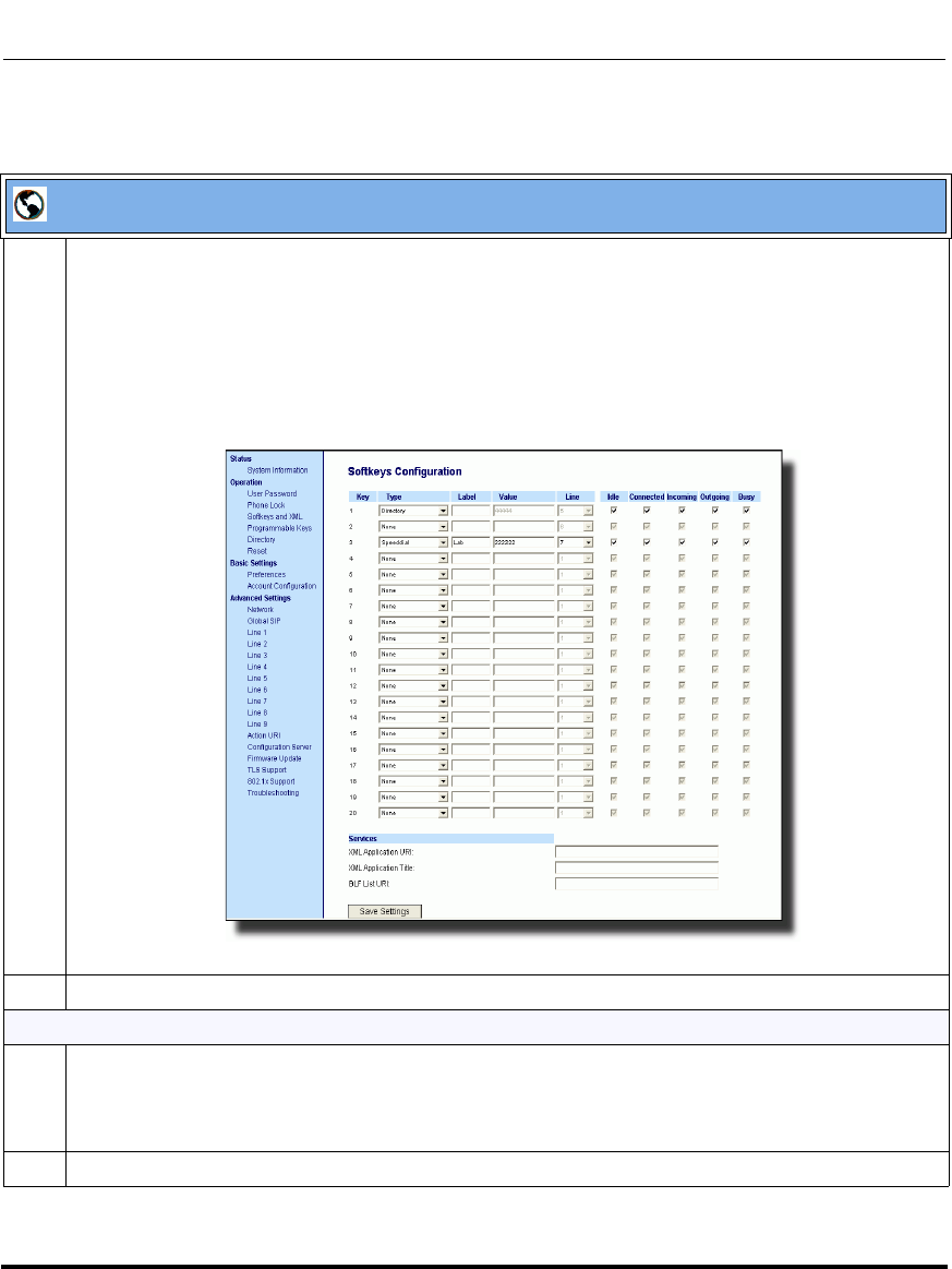
Operational Features
41-001160-03, Rev 00, Releaes 2.4 5-155
Configuring Operational Features
Aastra Web UI
1 Click on Operation->Softkeys and XML
or
Click on Operation->Programmable Keys
or
Click on Operation->Expansion Module <N>.
Depending on your phone-model, the key configuration screen displays. The 6757i Key Screen is
shown as an example.
2 Select a key to configure.
For Softkeys and Expansion Module Keys:
3 In the "Type" field, select the type of softkey you want to configure.
Reference: For available type values on each IP phone model, see Appendix A, the section,
“Softkey/Programmable Key/Feature Key/Expansion Module Key Parameters” on page A-192.
4 If applicable, enter a label in the “Label” field.
Draft 1
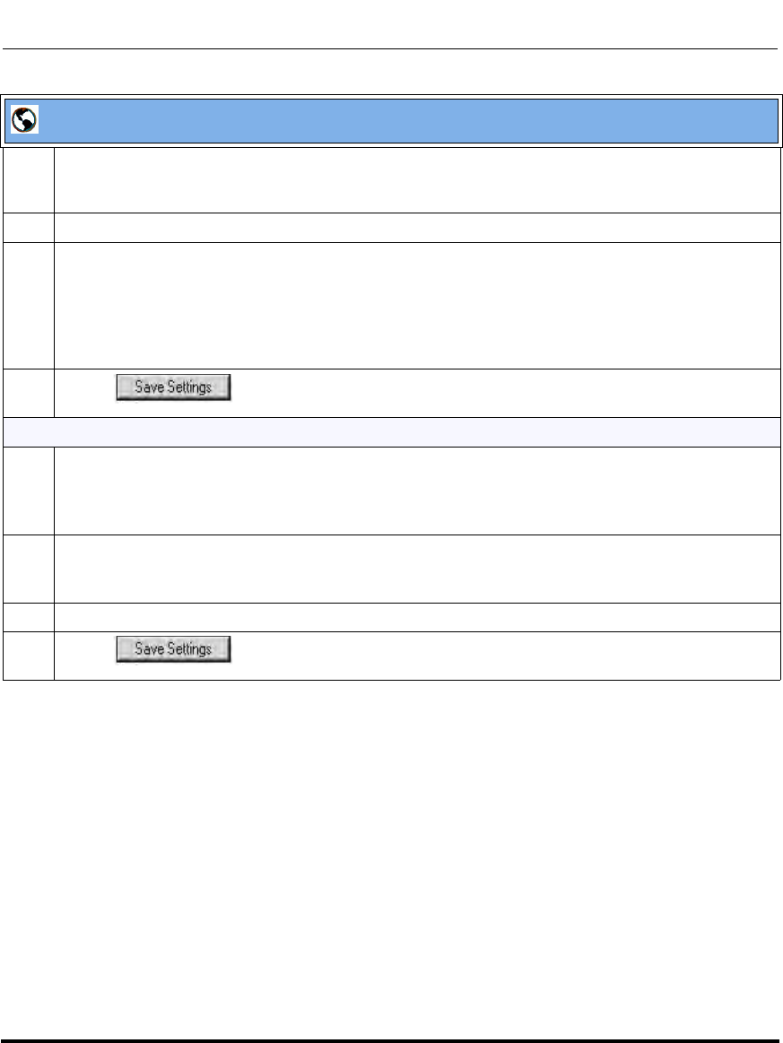
Operational Features
5-156 41-001160-03, Rev 00, Releaes 2.4
IP Phone Administrator Guide
5 If applicable, in the "Value" field, enter a value to associate with the softkey. For example, for a
speeddial value, you can enter a number you want to use for the speeddial key, or 12345+ as a
speeddial prefix.
6 If applicable, in the "Line" field, select the line for which you want to associate the softkey.
7 Some softkey types allow you to configure specific operational states.
Operational states display to the IP phone when a softkey is used.
To enable/disable an operational state, click the "Idle", "Connected", "Incoming", or "Outgoing"
fields to check or uncheck the box.
Note: Operational states are not applicable to expansion modules.
8 Click to save your changes.
For programmable keys:
9 In the “Hard Key” field, select the programmable key type you want to configure.
Reference: For available type values on each IP phone model, see Appendix A, the section,
“Softkey/Programmable Key/Feature Key/Expansion Module Key Parameters” on page A-192.
10 In the "Value" field, enter a value to associate with the programmable key. For example, for a
speeddial value, you can enter a number you want to use for the speeddial key, or 12345+ as a
speeddial prefix.
11 In the "Line" field, select the line for which you want to associate the programmable key.
12 Click to save your changes.
Aastra Web UI
Draft 1
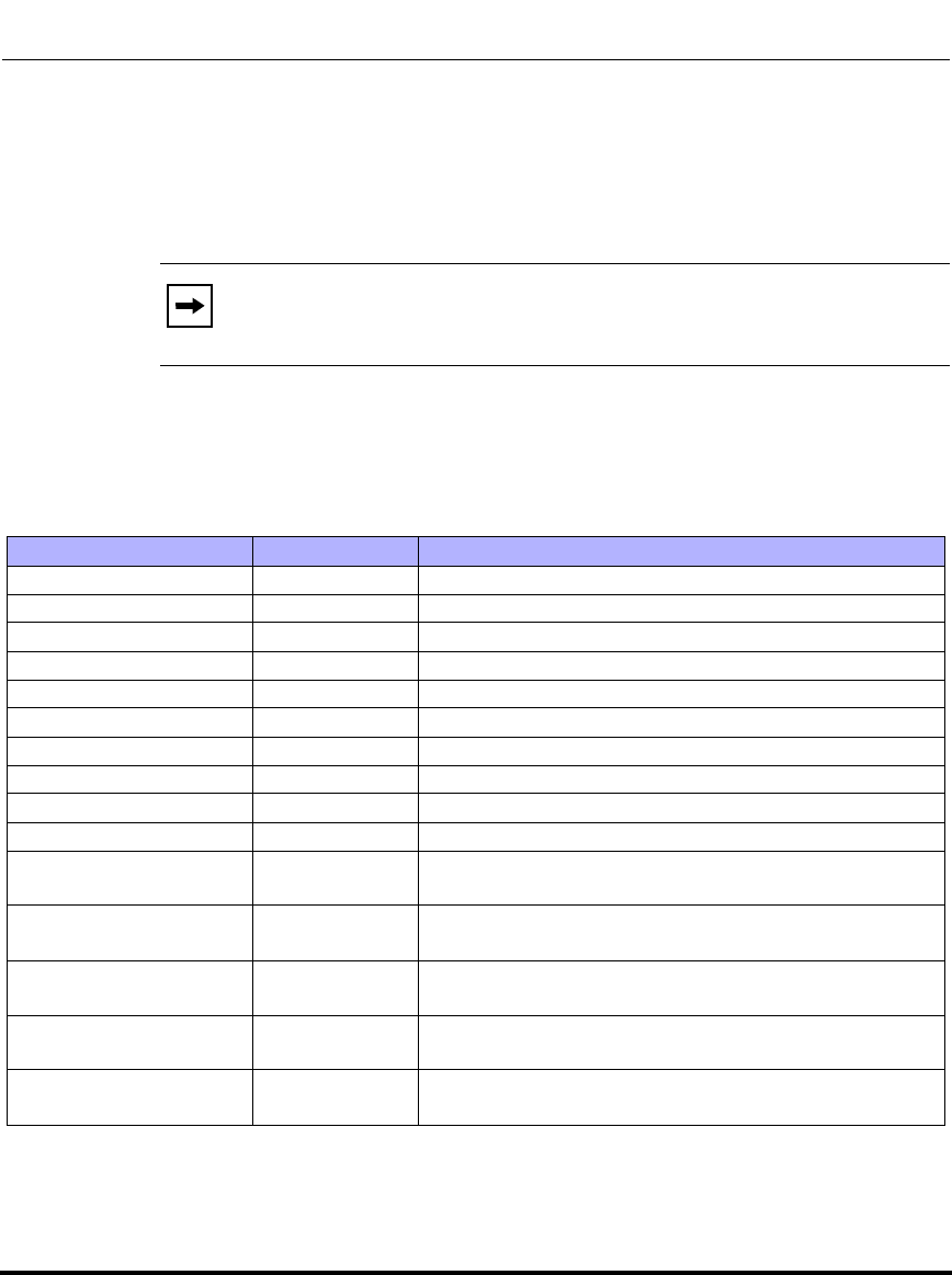
Operational Features
41-001160-03, Rev 00, Releaes 2.4 5-157
Configuring Operational Features
6757i Cordless (CT) Feature Keys
In addition to the softkeys on the 6757i CT, this phone also has handset keys you
can configure with specific features. You can use the Aastra Web UI to configure
the handset keys.
You can program up to 15 feature keys on the 6757i CT handset with specific
functions using the Aastra Web UI.
The following table identifies the functions available for all 15 handset keys and
the default functions for each key.
Note: You configure the handset keys using the Aastra Web UI
(Operation->Handset Keys) or by pressing the "F" button on the
handset.
Handset Key Key Function Description
1Line 1 Line 1 key - Selects line one
2Line 2 Line 2 key - Selects line two
3Line 3 Line 3 key - Selects line three
4Line 4 Line 4 key - Selects line four
5Icom Icom key – Enter handset list to select handset to call
6Dir Directory key – Activate directory feature
7Callers Callers key – Activate callers feature
8Xfer Transfer key - Activate transfer feature
9Conf Conference key - Activate conference feature
10 Public Public key – Toggle between public & private call mode
11 None No function selected. Line 5 key (if available) - Selects line
five.
12 None No function selected. Line 6 key (if available) - Selects line
six.
13 None No function selected. Line 7 key (if available) - Selects line
seven.
14 None No function selected. Line 8 key (if available) - Selects line
eight.
15 None No function selected. Line 9 key (if available) - Selects line
nine.
Draft 1

Operational Features
5-158 41-001160-03, Rev 00, Releaes 2.4
IP Phone Administrator Guide
Feature Key Programming Guidelines
The following are guidelines to use when programming the feature keys on the
handset:
• All handsets paired with the same Base Station have the same programmed
functions since the web interface applies the functions to all the handsets
paired with that base.
• A newly registered handset or handset that was out-of-range during the
programming needs to perform an "off-hook and on-hook" sequence in order
for the newly programmed function to be broadcasted to the affected
handsets. Simply press the v key from the idle state to go off-hook. Then,
press the y key to go back on-hook.
• Duplicate functions can exist in the feature key as there is no filtering or
duplicate checking done on the handset or the base.
• If no line keys are programmed for the feature key, the handset is restricted to
intercom calls only.
• If all 12 programmable functions have been programmed to "None", the user
is presented with a List empty message when the feature key is pressed.
• For security reasons, the user has 180 seconds (3 minutes) to complete the
programming. Otherwise, the phone displays the following error:
** Error **: Session expired, Please reload page.
• For security reasons, the user must submit the page from the same browser
that was used to load the page. If the user tries to submit the page from any
other IP address, the following error displays:
** Error ** Session invalid. Different Client IP Addresses. —
Please reload page
List empty
Use web page to
configure
Draft 1

Operational Features
41-001160-03, Rev 00, Releaes 2.4 5-159
Configuring Operational Features
Handset Feature Key Functions
You can configure the features keys on the 6757i CT handset to perform specific
functions using the configuration files or the Aastra Web UI.The following table
identifies the available functions for the feature keys on the 6757i CT handset.
The following Handset Key Functions Table lists the available functions for the
keys on the 6757i CT IP Phone.
Handset Key Functions Table
Feature Key
Function Configuration
File Parameter Aastra Web UI
Parameter Description
None none None Indicates the key is disabled.
This option is available from Web UI only.
Line
(Lines 1 through 9
are available for
selection)
line Line Indicates the key is configured for line use.
Icom icom Icom Indicates the key is set to be used as the
Intercom key.
For more information about the Icom key, see
your Aastra IP Phone 6757i CT User’s Guide.
For information about other Intercom features,
see “Incoming/Outgoing Intercom with
Auto-Answer and Barge In” on page 5-102.
Directory dir Dir Indicates the key is set for accessing the
Directory List.
For more information about the Directory List,
see the section “Directory List” on page -297.
Callers callers Callers Indicates the key is set for accessing the
Callers List.
For more information on the Callers List, see
the section “Callers List” on page -288.
Draft 1

Operational Features
5-160 41-001160-03, Rev 00, Releaes 2.4
IP Phone Administrator Guide
Transfer xfer Xfer Indicates the key is configured as a transfer
key for transferring calls.
For more information about the Xfer key, see
your Aastra IP Phone 6757i CT User’s Guide.
Park park Park Indicates the key is set to be used as a park
key to park an incoming call.
For more information on park, see the section
“Park/Pick Up Key” on page 5-234.
Pickup pickup PickUp Indicates the key is set to be used as a pickup
key to pick up a parked call.
For more information on pickup, see the
section “Park/Pick Up Key” on page 5-234.
Conference conf Conf Indicates the key is configured as a
conference key (for local conferencing).
(For Sylantro and Broadsoft Servers) An
Administrator can also enable centralized
conferencing on the IP Phones.
For more information about using the
Conference key, see your Aastra IP Phone
6757i CT User’s Guide.
For information about enabling centralizing
conferencing, see “Centralized Conferencing
(for Sylantro and Broadsoft Servers)” on
page 5-359.
Feature Key
Function Configuration
File Parameter Aastra Web UI
Parameter Description
Draft 1

Operational Features
41-001160-03, Rev 00, Releaes 2.4 5-161
Configuring Operational Features
Reference
For more information about features key functions for your 6757i CT, see your
Aastra IP Phone 6757i CT User’s Guide.
Public public Public Indicates the key is configured to toggle from
public to private mode. A public and private
key can be used when at a line item in the
Directory List. The Private key toggles a
number in the Directory List to private. The
Public key allows a number in the Directory
List to be sent to the handsets. A 6757i CT
accepts a maximum of 50 entries with the
public attribute.
For more information about the public/private
keys, see your Aastra IP Phone 6757i CT
User’s Guide.
Flash flash Flash Indicates the key is set to generate a flash
event when it is pressed, or when a feature
key is pressed on the 6757i CT cordless
handset. The IP phone generates flash events
only when a call is connected and there is an
active RTP stream (for example, when the call
is not on hold).
For more information about the Flash key, see
your Aastra IP Phone 6757i CT User’s Guide.
Feature Key
Function Configuration
File Parameter Aastra Web UI
Parameter Description
Draft 1

Operational Features
5-162 41-001160-03, Rev 00, Releaes 2.4
IP Phone Administrator Guide
Configuring Handset Feature Keys
You can program up to 15 feature keys on the 6757i CT IP phone using the
configuration files or the Aastra Web UI. Use the following procedure to program
the feature keys on your 6757i CT Base Station and all paired handsets.
Use the following procedures to configure the IP phone handset feature keys.
Configuration Files
For specific parameters you can set in the configuration files, see Appendix A, the section,
“Handset Feature Key Settings for the 9480i CT and 6757i CT” on page A-214.
Draft 1
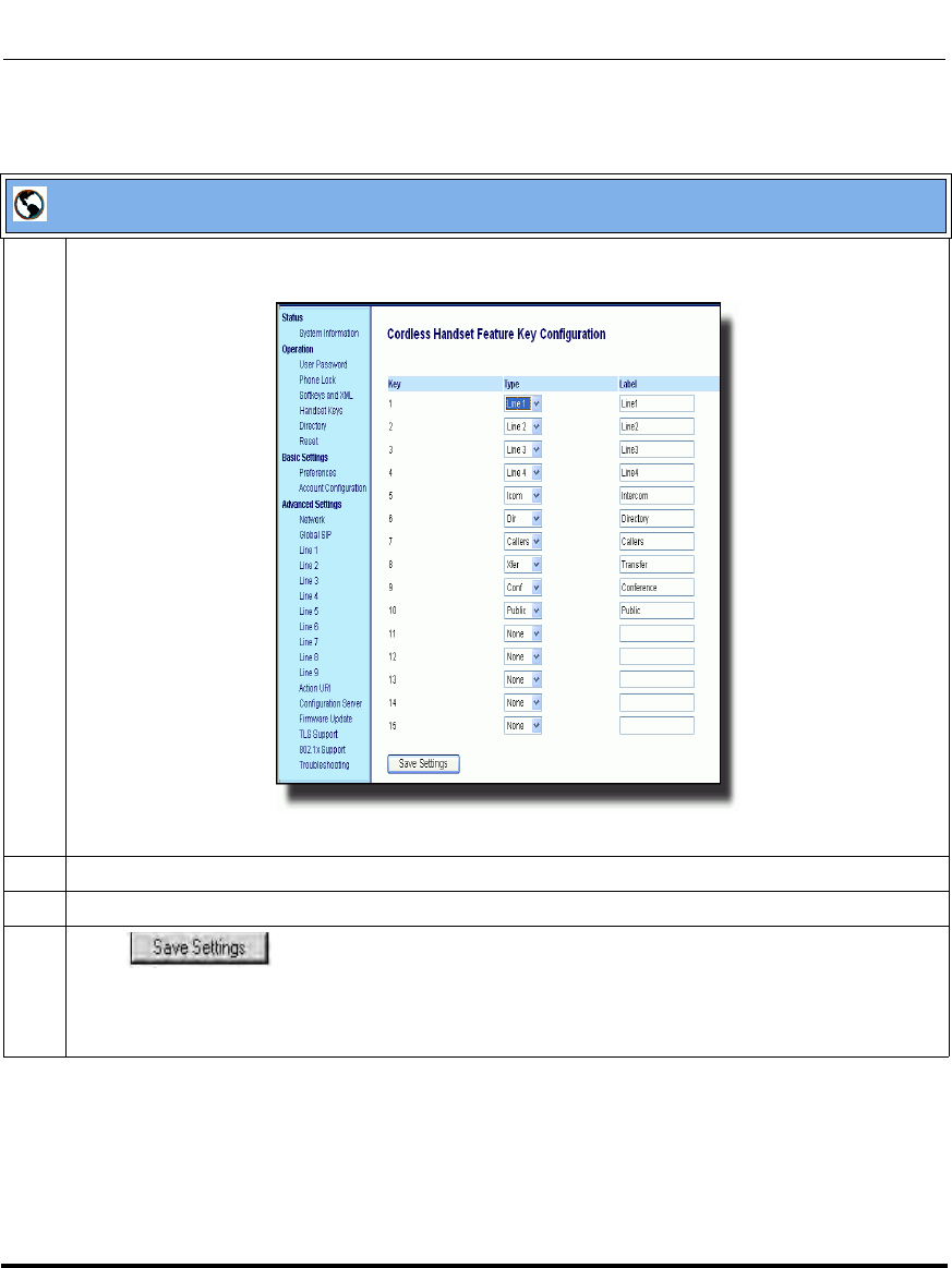
Operational Features
41-001160-03, Rev 00, Releaes 2.4 5-163
Configuring Operational Features
Aastra Web UI
1 Click on Operation->Handset Keys.
2 Select the handset key you want to program.
3 Select the function for that handset key from the "Key Function" field.
4 Click to save the function you selected to the handset key.
The key programming information is sent to the 6757i Base Station and to all the cordless handsets
associated with that Base Station. Any key programmed to "None" does not appear in the handset’s
list.
Draft 1

Operational Features
5-164 41-001160-03, Rev 00, Releaes 2.4
IP Phone Administrator Guide
Customizing the Key Type List in the Aastra Web UI
An Administrator can configure which key types display in the Aastra Web UI list
for a Softkey, Programmable Key, Expansion Module Key, and/or Feature Key
(CT Models). Currently, in the Aastra Web UI for a phone, you can select a type of
key from a list of approximately 26 key types to assign to a softkey,
programmable key, expansion module key, and/or feature key.
Using the configuration files, you can specify key types to display in the key type
list that apply to a User’s environment.
List of Available Keys Types
Draft 1
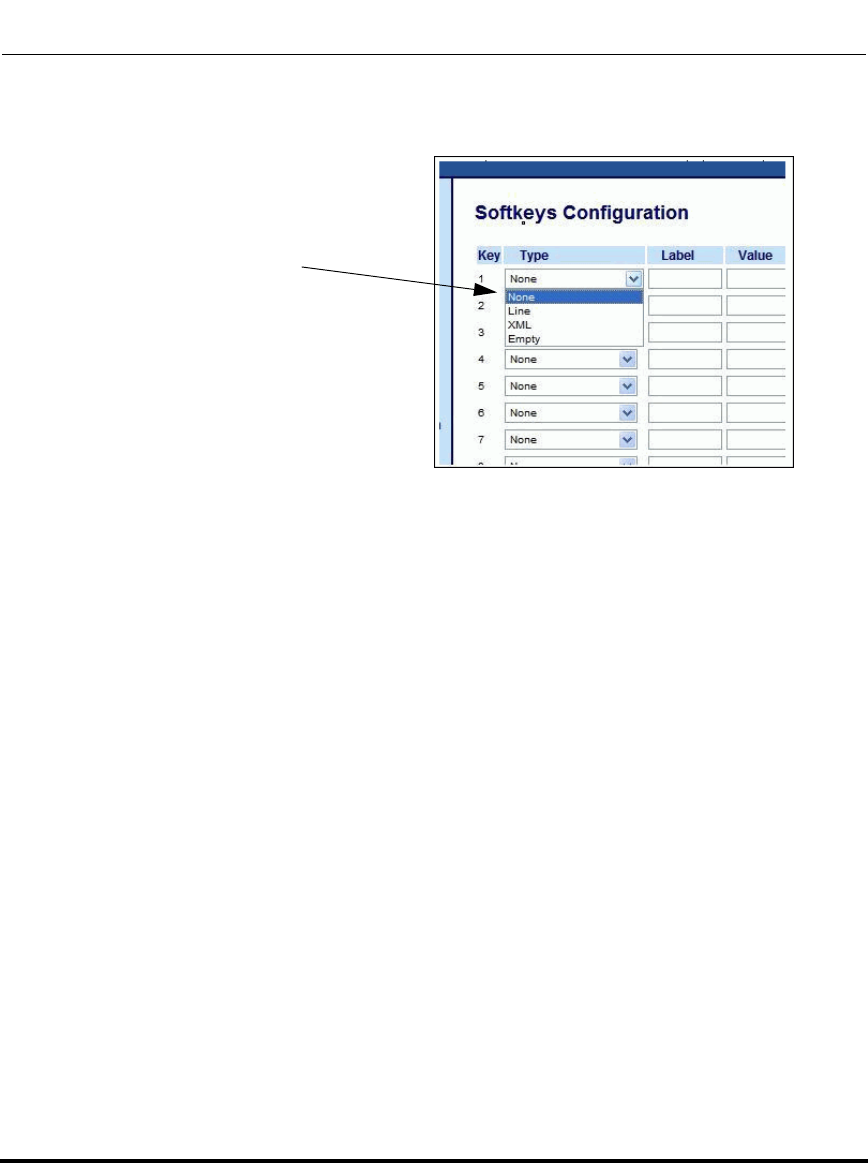
Operational Features
41-001160-03, Rev 00, Releaes 2.4 5-165
Configuring Operational Features
In addition to being able to specify which key types display in the list, the
Administrator can also determine in which order the key types display.
You can use the following configuration file parameters to control which key
types to display and specify in which order to display them in:
• softkey selection list
• feature key selection list
If no value is specified for the “softkey selection list” and/or “feature key
selection list” parameters, the key “Type” list displays all of the key types by
default.
If an Administrator configures specific key types for a phone in the configuration
file, and the phone for which he downloads the configuration to already has key
types configured on it, those key types display in the key list for those keys, in
addition to the key types specified by the Administrator. For example, a phone has
a Park key and a Pickup key already configured on the phone, and the
Administrator downloads a configuration file to the phone that has specific key
types of None, Line, Speeddial, and XML. After the configuration file is
downloaded, the Park key list will show None, Line, Speeddial, XML, and Park;
the Pickup key list will show None, Line, Speeddial, XML, and Pickup; all other
keys that were configured as None before the download will show only None,
Line, Speeddial, and XML.
Example of a
List of Configured Keys Types
(None, Line, XML, Empty)
Draft 1
Operational Features
5-166 41-001160-03, Rev 00, Releaes 2.4
IP Phone Administrator Guide
Customizing the Key Type List Using the Configuration Files
Use the following procedure to configure the Key Type List that displays in the
Aastra Web UI.
Notes:
1. Any key types configured that do not apply to the phone are
ignored.
2. The SAVE and DELETE keys appear by default as Keys 1 and 2 on
the 6753i and 9143i, unless specifically allowed by the Administrator to
be configurable.
3. An Administrator must use the English value when configuring the
key types in the configuration files.
5. After configuring specific key types for a phone, the key types in
the Aastra Web UI display the same for both the User and Administrator
Web interfaces for that phone.
Configuration Files
For specific parameters you can set in the configuration files, see Appendix A, the section,
“Customizing the Key Type List” on page A-223.
Draft 1

Operational Features
41-001160-03, Rev 00, Releaes 2.4 5-167
Configuring Operational Features
Speeddial Prefixes
The normal function of the speeddial option allows you to configure a specific
key on the phone to dial a number quickly by pressing the configured key. For
example, if you had the following speeddial configuration in the configuration
files:
softkey1 type: speeddial
softkey1 label: Office
softkey1 value: 5552345
softkey1 line: 1
after you press softkey1 on the phone, it dials the Office number at 555-2345 on
line 1.
A new feature for the speeddial option allows you to configure a preset string of
numbers followed by a “+”. This feature allows the phone to speeddial a prefix
number and then pause to let you enter the remaining phone number. You can use
this feature for numbers that contain long prefixes. For example, if you had the
following speeddial configuration in the configuration files:
softkey2 type: speeddial
softkey2 label: Europe Office
softkey2 value: 1234567+
softkey2 line: 2
after you press softkey2 on the phone, it dials the prefix number automatically and
pauses for you to enter the remaining number using the keypad on the phone.
You can configure the speeddial prefix using the configuration files or the Aastra
Web UI.
Draft 1
Operational Features
5-168 41-001160-03, Rev 00, Releaes 2.4
IP Phone Administrator Guide
Enabling/Disabling Ability to Add or Edit a Speeddial Key
The IP Phones allow you to set a parameter, “speeddial edit” using the
configuration files that allows you to enable or disable the ability to add a
speeddial key or edit a speeddial key from the IP Phone UI. Disabling this
parameter prevents a user from adding or editing a speeddial key.
The default for this parameter is enabled, allowing you to create and edit
speeddial keys on the phone using the Press-and-hold feature, softkeys,
programmable keys, expansion module keys and key pad, speeddial menu in the
IP Phone UI, and the SAVE TO key.
If this parameter is set to disabled, it blocks the user from using any of the features
on the phone to create or edit a speeddial key.
Enabling/Disabling the Ability to Add or Edit a Speeddial Key Using
the Configuration Files
Use the following procedure to enable/disable the ability to add and edit a
speeddial key.
Configuration Files
For specific parameters you can set in the configuration files, see Appendix A, the section,
“Enabling/Disabling Ability to Add/Edit Speeddial Keys” on page A-230.
Draft 1
Operational Features
41-001160-03, Rev 00, Releaes 2.4 5-169
Configuring Operational Features
Busy Lamp Field (BLF)
The BLF feature on the IP phones allows a specific extension to be monitored for
state changes. BLF monitors the status (busy or idle) of extensions on the IP
phone.
Example
A Supervisor configures BLFs on his phone for monitoring the status of a
worker’s phone use (busy or idle). When the worker picks up his phone to make a
call, a busy indicator on the Supervisor’s phone shows that the worker’s phone is
in use and busy.
BLF Setting (For use with Asterisk)
On the 9480i, 9480i CT, 6755i, 6757i, and 6757i CT, the busy and idle indicators
show on the IP phone screen display next to the softkey or programmable key
configured for BLF functionality. When the monitored user is idle, an icon with
the handset on-hook shows next to the BLF softkey or programmable key. When
the monitored user is on an active call, a small telephone icon is shown with the
handset off-hook.
On the 9143i, 6751i, and 6753i, the LED lights next to each BLF programmable
key illuminate steady to indicate the monitored line is off-hook or unregistered.
The LED goes off when the line is idle.
You can configure a BLF key on the IP Phones using the configuration files or the
Aastra Web UI.
Note: The BLF setting is applicable to the Asterisk server only.
Note: You can configure a maximum of 50 BLFs on the M670i and
M675i Expansion Modules.
Draft 1
Operational Features
5-170 41-001160-03, Rev 00, Releaes 2.4
IP Phone Administrator Guide
BLF\List Setting
(For use with the BroadSoft Broadworks Rel 13 or higher platform only)
The BLF\List feature on the IP phones is specifically designed to support the
BroadSoft Broadworks Rel 13 Busy Lamp Field feature. This feature allows the
IP phone to subscribe to a list of monitored users defined through the BroadWorks
web portal.
In addition to monitoring the idle and busy state, the BLF\List feature also
supports the ringing state. When the monitored user is idle, there is a small
telephone icon shown with the handset on-hook. When the monitored user is in
ringing state, there is a small bell icon shown. When the monitored user is on an
active call then a small telephone icon is shown with the handset off-hook.
On the 9143i and 6753i phone, the LED lights next to each BLF programmable
key illuminate steady to indicate the monitored line is off-hook or unregistered.
The LED goes off when the is idle. When the monitored extension is ringing, the
LED flashes.
You can configure a BLF/List key on the IP Phones using the configuration files
or the Aastra Web UI. You can also specify a BLF list URI that the phone uses to
access the required BLF list. You can specify a BLF List URI using the “list uri”
parameter in the configuration files or the BLF List URI field in the Aastra Web
UI at the path Operation->Softkeys/Programmable Keys/Expansion Module
Keys->Services->BLF List URI. For more information about the “list uri”
parameter, see Appendix A, the section, “BLF List URI Settings” on page A-230.
Example
A receptionist has a 6757i running Broadsoft firmware that subscribes to a list of
extensions from the BroadWorks Application Server. Each monitored extension
in the list shows up individually on the 6757i screen next to a softkey button. The
softkey icons on the screen change depending on the state of the extensions.
Note: The Broadworks BLF feature is not the same as the Broadworks
Shared Call Appearance (SCA) feature and does not permit call control
over the monitored extension.
Draft 1

Operational Features
41-001160-03, Rev 00, Releaes 2.4 5-171
Configuring Operational Features
On the 9143i, 6751i, and 6753i running Broadsoft firmware, the programmable
key LEDs illuminate either flashing, solid, or turn off depending on the state of
those extensions.
Draft 1

Operational Features
5-172 41-001160-03, Rev 00, Releaes 2.4
IP Phone Administrator Guide
Asterisk BLF Configuration
You can enable the BLF feature on Asterisk to enable monitoring for specific
extensions. BLF on Asterisk is possible through the “hint” extension parameter.
Add the following in the Asterisk extensions.conf file for each target extension
being monitored.
For example:
exten -> 9995551212,hint,SIP/9995551212
Add the following in the Asterisk sip.conf file for each subscriber if it is not
defined already.
For example:
[9995551212]
Subscribecontext=sip
BroadSoft BLF Configuration
You can enable the BLF feature on BroadSoft BroadWorks Rel 13 or higher
through the BroadWorks Web Portal. Each user must have the Busy Lamp Field
service enabled for their user. The user must add each desired extension to the
“Monitored Users List” on the Busy Lamp Field service page and also enter in a
list name for the monitored users BLF list on the same page.
Changes to the “Monitored Users List” are dynamic and the Aastra IP phones are
automatically updated without requiring a restart.
Reference
For sample BLF configurations, see Appendix D, “Sample BLF Softkey
Settings.”
Draft 1

Operational Features
41-001160-03, Rev 00, Releaes 2.4 5-173
Configuring Operational Features
Configuring BLFs
Use the following procedures to configure BLF and BLF\List on the IP phone.
Configuration Files
To set BLF or BLF\List in the configuration files, see Appendix A, the sections,
•“Softkey/Programmable Key/Feature Key/Expansion Module Key Parameters” on page A-192.
•“BLF List URI Settings” on page A-230.
Draft 1
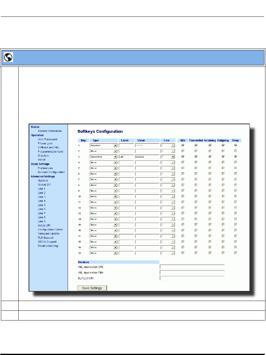
Operational Features
5-174 41-001160-03, Rev 00, Releaes 2.4
IP Phone Administrator Guide
Aastra Web UI
1 Click on Operation->Softkeys and XML
or
Click on Operation->Programmable Keys
or
Click on Operation->Expansion Module <N>.
Depending on your phone-model, the key configuration screen displays. The 6757i Key Screen is
shown as an example.
2 Select a softkey, programmable, or expansion module key to configure.
3 In the "Type" field, select "BLF" (Asterisk), "BLF\List" (BroadSoft BroadWorks).
Draft 1
Operational Features
41-001160-03, Rev 00, Releaes 2.4 5-175
Configuring Operational Features
4For the 9480i, 9480i CT, 6755i, 6757i, and 6757i CT softkeys:
In the "Label" field, enter the name of the person who’s extension you are monitoring (if “Type” is
BLF).
Note: If BLF\List type is selected, no label value is required. The BroadWorks BLF List name is
configured in the "BLF List URI" field instead.
5 In the "Value" field, enter a value to associate with the softkey or programmable key.
For example, for BLF, the value is the extension you want to monitor.
For BLF\List, the value is an identifier for the list of numbers you are monitoring.
6 Click to save your changes.
7In the "Line" field, select a line number that is actively registered to the appropriate SIP proxy you are
using.
8 In the "BLF List URI" field, enter the name of the BLF list defined on the BroadSoft BroadWorks
Busy Lamp field page for your particular user.
For example, my6757i-blf-list@as.broadworks.com.
Note: The value of the BLF\List URI parameter must match the list name configured. Otherwise, no
values display on the 6757i screen and the feature is disabled.
9 Click to save your changes.
Aastra Web UI
Draft 1

Operational Features
5-176 41-001160-03, Rev 00, Releaes 2.4
IP Phone Administrator Guide
BLF Subscription Period
On the IP phones, you can set the time period, in seconds, that the IP phone
resubscribes the BLF subscription service after a software/firmware upgrade or
after a reboot of the IP phone.
In the configuration files, you enter the following parameter with a valid value to
set the BLF subscription period:
sip blf subscription period: <value in seconds>
The minimum value for this 120 seconds (2 minutes). The default is 3600 (1
hour).
Setting this parameter to a value lower than 3600 allows the configured BLF
feature to become active more quickly after a software/firmware upgrade or after
a reboot of the IP phone. If you enter a value lower than 120 for this parameter,
the default value (3600) will be used by the IP phone.
You can configure this feature using the configuration files or the Aastra Web UI.
Configuring BLF Subscription Period
Use the following procedures to configure the BLF subscription period on the IP
phone.
Configuration Files
To configure the BLF subscription period on the IP phones using the configuration files, see Appendix A, the
section, “Advanced SIP Settings” on page A-92.
Draft 1

Operational Features
41-001160-03, Rev 00, Releaes 2.4 5-177
Configuring Operational Features
Aastra Web UI
1 Click on Advanced Settings->Global SIP->Advanced SIP Settings.
2 Enter a value, in seconds, from 120 (2 min) to 3600 (1 hour) in the "BLF Subscription Period" field.
3 Click to save your changes.
Draft 1
Operational Features
5-178 41-001160-03, Rev 00, Releaes 2.4
IP Phone Administrator Guide
BLF/Xfer and Speeddial/Xfer Keys
The IP Phones have a transfer (Xfer) enhancement feature you can use with the
BLF and Speeddial keys - BLF/Xfer and Speeddial/Xfer.
The BLF key allows one or more extensions to be monitored, and once there is
any state change with those extensions, the key shows the status of the monitored
lines. The Xfer key allows a call to be transferred to other recipients blindly or
consultatively.
The Speeddial key allows a number to be dialed quickly by pressing one key
configured for speeddialing. After answering a call, the recipient can transfer the
call to an extension by:
1. Pressing Xfer key
2. Entering the number of the extension or pressing speeddial or BLF key.
3. Pressing Xfer key again
The BLF and Speeddial transfer enhancement feature provides a simpler way of
transferring calls using the keys called BLF/Xfer and Speeddial/Xfer. The BLF/
Xfer key combines the BLF and Xfer key's functionality together allowing the
user to transfer calls or use BLF with one key. Similarly, the Speeddial/Xfer key
combines the Speeddial key and Xfer key's functionality together allowing the
user to press one key to speeddial and transfer calls.
Note: It is recommended that you enable the “switch focus to
ringing” parameter when using the BLF and Speeddial transfer key
feature. For more information about this parameter, see “Switch Focus
to Ringing Line” on page 5-79.
Draft 1

Operational Features
41-001160-03, Rev 00, Releaes 2.4 5-179
Configuring Operational Features
BLF/Xfer Key Requirements and Functionality
•BLF/Xfer and BLF
A BLF/Xfer key can be configured for subscribing to an extension and
monitor the status of the extension, similar to the BLF key functionality.
Changes of the state of the monitored extension are indicated by a LED / Icon.
• BLF/Xfer and Blind Transfer Calls
When the focused line is in the “Connected” state, pressing the BLF/Xfer key
transfers the call to the extension unconditionally, disregarding the status of
the monitored extension.
If transferring a call to an extension fails, a message “Transfer Failed”
displays on the phone, and you can reconnect the call (get the call back) by
pressing the line key again.
• BLF/Xfer and Call forward
When the focused line is in the “Ringing” state, pressing the BLF/Xfer key
forwards the call to the extension unconditionally, disregarding the status of
the monitored extension.
• BLF/Xfer and Speeddial
When the focused line and the monitored extension are idle, pressing the
BLF/Xfer key causes the phone to go offhook and dial the number of the
extension.
Draft 1

Operational Features
5-180 41-001160-03, Rev 00, Releaes 2.4
IP Phone Administrator Guide
Speeddial/Xfer Key Requirements and Functionality
The Speeddial/Xfer key has the following capabilities:
•Speeddial/Xfer and Speeddial
When the phone is in the “Idle” state, pressing the Speeddial/Xfer key causes
the phone to go offhook and dial the predefined extension.
•Speeddial/Xfer and Blind Transfer
When the phone is connected to a call, pressing the Speeddial/Xfer key blind
transfers the call to the predefined target.
If transferring a call fails, a message “Transfer Failed” displays, and you can
reconnect the call (get the call back) by pressing the line key again.
•Speeddial/Xfer and Call Forward
When the phone is in the “Ringing” state, pressing the Speeddial/Xfer key
forwards the call to the predefined extension.
Draft 1
Operational Features
41-001160-03, Rev 00, Releaes 2.4 5-181
Configuring Operational Features
Configuring the BLF/Xfer Key and the Speeddial/Xfer Key Using the
Configuration Files
You use the following parameters in the configuration files to configure the
BLF/Xfer key and/or Speeddial/Xfer key on the IP Phone.
Examples:
softkey1 type: speeddialxfer
softkey1 label: BX7801
softkey1 value: 7801
softkey1 line: 1
softkey1 states: idle connected incoming outgoing busy
prgkey1 type: blfxfer
prgkey1 value: 35
prgkey1 line: 1
Refer to the following in Appendix A to configure a BLF/Xfer and Speeddial/Xfer
key on the IP phone using the configuration files.
Softkey Parameters Programmable Key Parameters Expansion Module Parameters
softkeyN type
softkeyN label
softkeyN value
softkeyN line
softkeyN states
prgkeyN type
prgkeyN value
prgkeyN line
expmodN keyN type
expmodN keyN label
expmodN keyN value
expmodN keyN line
Top Softkey Parameters
topsoftkeyN type
topsoftkeyN label
topsoftkeyN value
topsoftkeyN line
Configuration Files
To set a BLF/Xfer and Speeddial/Xfer key using the configuration files, see Appendix A, “Softkey/
Programmable Key/Feature Key/Expansion Module Key Parameters” on page A-192.
Draft 1
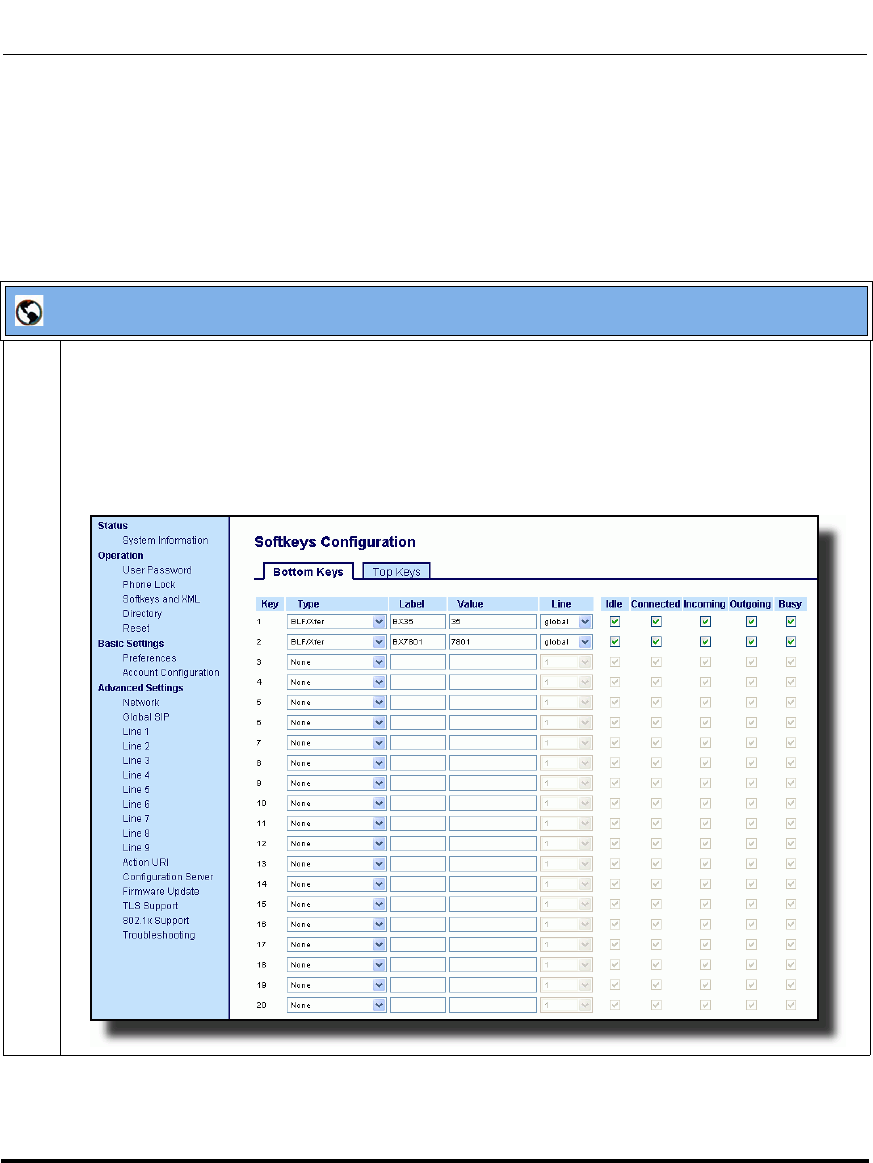
Operational Features
5-182 41-001160-03, Rev 00, Releaes 2.4
IP Phone Administrator Guide
Configuring the BLF/Xfer Key and the Speeddial/Xfer Key Using the
Aastra Web UI
You configure the BLF/Xfer key and/or the Speeddial/Xfer Key on the IP phone
similar to configuring a BLF key or speeddial key using the Aastra Web UI. Use
the following procedure to configure BLF/Xfer and/or Speeddial/Xfer.
Aastra Web UI
1 Click on Operation->Softkeys and XML.
or
Click on Operation->Programmable Keys.
or
Click on Operation->Expansion Keys.
Bottom Keys Tab (6757i example).
Draft 1
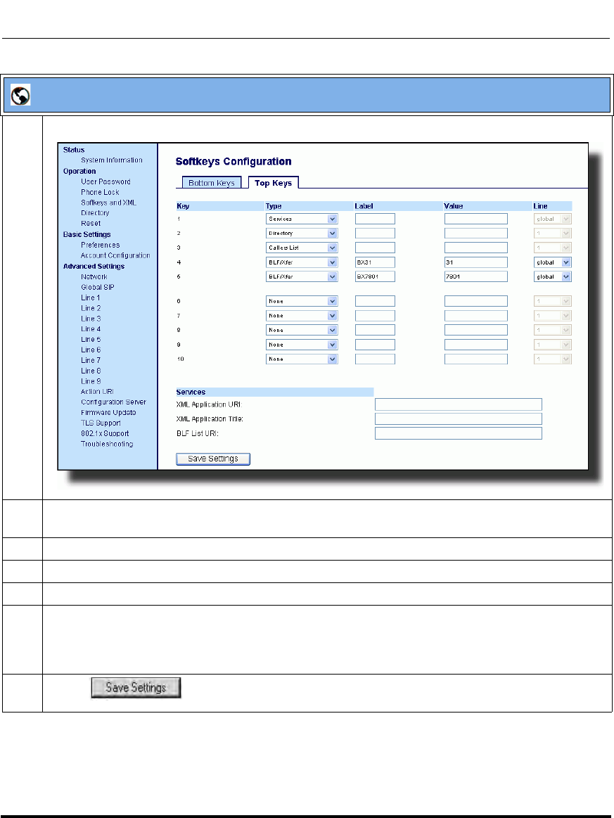
Operational Features
41-001160-03, Rev 00, Releaes 2.4 5-183
Configuring Operational Features
Top Keys Tab (6757i example)
2 Choose a key that you want to assign the BLF/Xfer key or a Speeddial/Xfer key to, and select BLF/
Xfer or Speeddial/Xfer from the “Type” field.
3 In the “Label” field, enter a key label to assign to the BLF/Xfer key (for example, “BX35”).
4 In the “Value” field, enter the monitored extension (for example, “35”).
5 In the “Line” field, select the line for which you want to use the key functionality.
6 On the Bottom Key tab, in the States field, select the state(s) (idle, connected, incoming, outgoing,
busy) for which you want to use on the key.
Note: States are not applicable to programmable keys.
7 Click to save your changes.
Aastra Web UI
Draft 1
Operational Features
5-184 41-001160-03, Rev 00, Releaes 2.4
IP Phone Administrator Guide
Speeddial/Conference Key (not applicable to the 6751i)
The IP Phones allow you to configure a softkey/programmable key/expansion
module key to be used as a speeddial conference key (Speeddial/Conf key) while
remaining in the current call. This key allows a user on a call, to conference
another party at a pre-defined number while remaining in the conference.
For example, while on an active call, a user can use the Speeddial/Conf key to dial
a recording service and have the resulting conference recorded.
How it Works
If you configure a softkey/programmable key/expansion module as a Speeddial/
Conf key, and you press this key while on an active call, the focused line changes
to the dialing line. A Cancel softkey displays on the phone (only those phones
that have LCDs larger then 3 lines), allowing you to abort the conference
speeddial if required. The message "Ringing..." displays below the number when
the far end is ringing. The message "Conf. Unavailable" briefly displays when a
conference is already in progress or when the CT handset is in use. The active call
is not put on hold when the speeddial number is dialed.
Limitations for Speeddial/Conference Key
The following are limitations for the Speeddial/Conference key:
• The CT handsets are not supported.
• The feature is not compatible with centralized conferencing.
The softkey/programmable key is called "Speeddial/Conf" in the Web UI drop
down list. In the configuration file, use "speeddialconf" as the softkey type.
Note: If not currently in a conference, the Speeddial/Conf key is disabled
on the active call.
Draft 1
Operational Features
41-001160-03, Rev 00, Releaes 2.4 5-185
Configuring Operational Features
Configuring the Speeddial/Conf Key Using the Configuration Files
To configure the Speeddial/Conf key using the configuration files, you enter
“speeddialconf” for the key type. The following parameters are examples you
can use to configure the Speeddial/Conf key:
softkey1 type: speeddialconf
softkey1 label: Sales
softkey1 value: 5645
softkey1 line: 3
topsoftkey1 type: speeddialconf
topsoftkey1 label: Sales
topsoftkey1 value: 5645
topsoftkey1 line: 3
prgkey1 type: speeddialconf
prgkey1 value: 5645
prgkey1 line: 1
expmod1 key1 type: speeddialconf
expmod1 key1 label: Sales
expmod1 key1 value: 5645
expmod1 key1 line: 3
Refer to the following in Appendix A to configure a Speeddial/Conf key on the IP
phone using the configuration files.
Configuration Files
To set a Speeddial/Conf key using the configuration files, see Appendix A, “Softkey/Programmable Key/
Feature Key/Expansion Module Key Parameters” on page A-192.
Draft 1
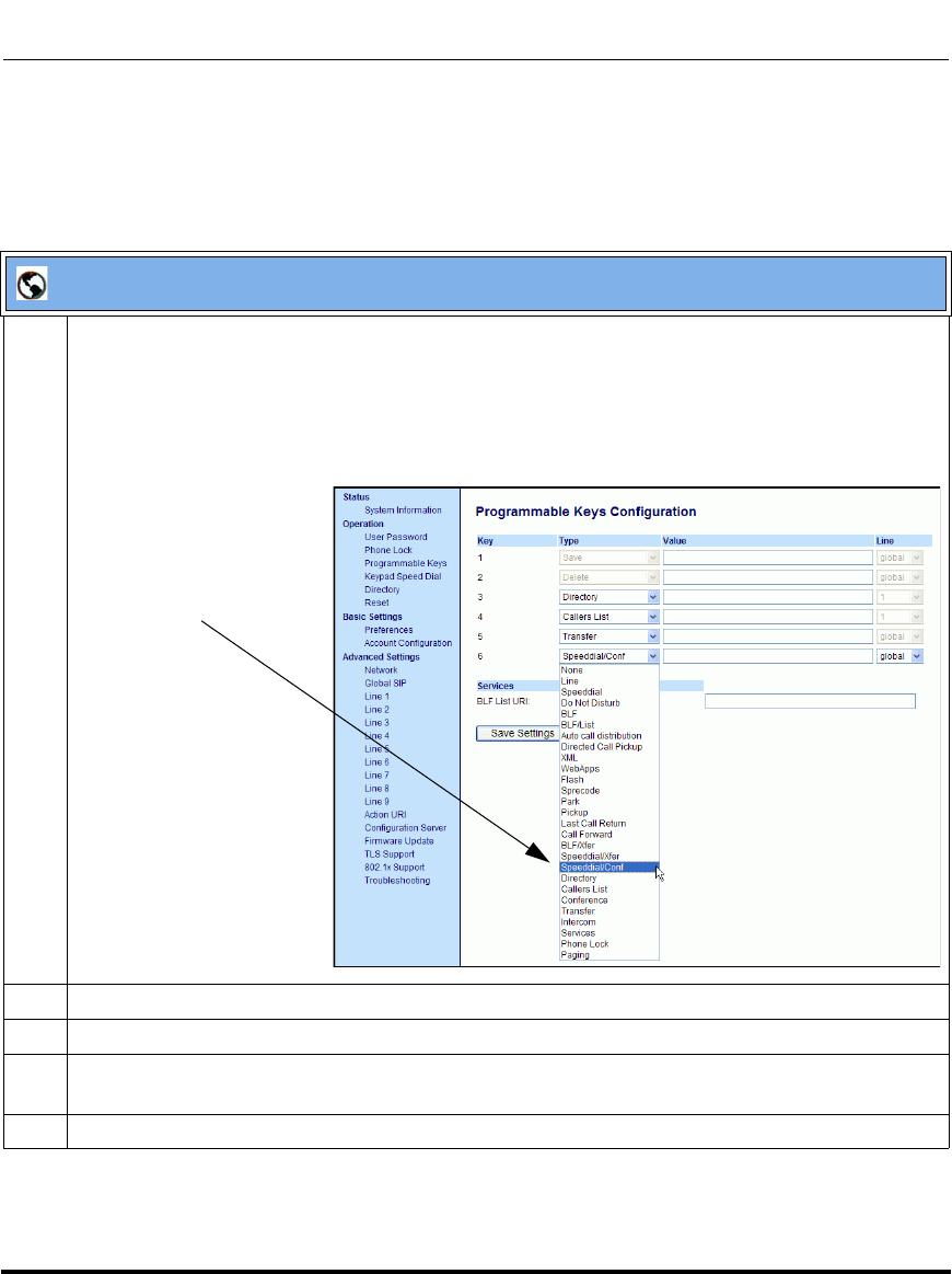
Operational Features
5-186 41-001160-03, Rev 00, Releaes 2.4
IP Phone Administrator Guide
Configuring the Speeddial/Conf Key Using the Aastra Web UI
Use the following procedure to configure the Speeddial/Conf Key using the
Aastra Web UI.
Aastra Web UI
1 Click on Operation->Sottkeys and XML.
or
Click on Operation->Programmable Keys.
or
Click on Operation->Expansion Module Keys.
2 In the “Type” field, select Speeddial/Conf from the list of options.
3 In the “Label” field, enter a key label to assign to the Speeddial/Conf key (for example, “Sales”).
4 In the “Value” field, enter the number that the phone dials when the Speeddial/Conf key is pressed
(for example, “4556”).
5 In the “Line” field, select the line for which you want to use the key functionality.
Speeddial/Conf
Option
Draft 1
Operational Features
41-001160-03, Rev 00, Releaes 2.4 5-187
Configuring Operational Features
6For phones with softkeys:
In the States field, select the state(s) (idle, connected, incoming, outgoing, busy) for which you want
to use on the key.
Note: States are not applicable to programmable keys (6753i, 9143i).
7 Click to save your changes.
Aastra Web UI
Draft 1

Operational Features
5-188 41-001160-03, Rev 00, Releaes 2.4
IP Phone Administrator Guide
Automatic Call Distribution (ACD) (for Sylantro Servers)
The IP phones support an Automatic Call Distribution (ACD) feature for Sylantro
servers. The ACD feature allows the Sylantro server to distribute calls from a
queue to registered IP phone users (agents).
To use the ACD feature on an IP phone, the administrator must first configure an
an ACD softkey or programmable key. When an IP phone user wants to subscribe
to a queue (in order to receive incoming calls), the user presses the ACD key. The
IP phone UI prompts the user to specify the following information:
•User ID: the phone number(s) used to login into the queue.
•Password: the password used to login to the queue.
•Available/unavailable: Shows the current status of the IP phone. Specifies if
the IP phone user is available/unavailable to receive a call from the queue.
This parameter is set to “unavailable” by default.
When the IP phone user is ready to receive calls from the server, the user logs into
a queue. Depending on the server configuration, the IP phone is either in an
“unavailable” or “available” state. If the phone is set to “available” then the server
begins to distribute calls to this phone immediately. If the phone is set to
unavailable, then server waits until the IP phone user manually changes the phone
status to “available” (using the IP phone UI) before distributing calls.
Whenever the IP phone user answers a call, or misses a call, the server
automatically changes the phone’s status to unavailable. The server updates it
database with this new information and no longer distributes calls to this phone.
The IP phone will remain in this state until:
— the IP phone user makes himself “available” again.
— the ACD auto-availability timer expires. This occurs only if the
administrator has configured an ACD auto-availability timer as described
in “ACD Auto-Available Timer” on page 5-189.
The IP phone user can also choose to manually change the phone status to
unavailable, using the IP Phone UI.
Note: It is recommended you configure no more than a single ACD
softkey or programmable key per IP phone.
Draft 1
Operational Features
41-001160-03, Rev 00, Releaes 2.4 5-189
Configuring Operational Features
ACD Auto-Available Timer
Whenever the IP phone user answers a call, or misses a call, the server
automatically changes the phone’s status to unavailable. The administrator can
control how long the IP phone remains in the unavailable state by configuring an
auto-available timer. When the timer expires, the IP phone status is automatically
changed to available. The default setting for the timer is 60 seconds.
You use the following parameters to configure an ACD Auto-Available Timer in
the configuration files:
• acd auto available
• acd auto available timer
Configuring an Automatic Call Distribution (ACD) Key
You can configure an ACD key on softkeys, programmable keys, and extension
module keys. The following table illustrates examples of configuring an ACD key
on the phone.
Use the following procedures to configure an ACD key n the IP phone.
Softkey Examples Top Softkey Examples Programmable Key
Examples Extension Module
Examples
softkey1 type: acd
softkey1 label: sales
softkey1 line: 1
softkey1 states: idle
topsoftkey1 type: acd
topsoftkey1 label: sales
topsoftkey1 line: 1
topsoftkey1 states: idle
prgkey1 type: acd
prgkey1 line: 1: expmod1 key1 type: acd
expmod1 key1 label: sales
expmod1 key 1 line: 1
Configuration Files
To configure an ACD key using the configuration files, see Appendix A, the section, “Softkey/Programmable
Key/Feature Key/Expansion Module Key Parameters” on page A-192.
Draft 1

Operational Features
5-190 41-001160-03, Rev 00, Releaes 2.4
IP Phone Administrator Guide
Configuring the ACD Auto-Available Timer.
Configuration Files
To configure the ACD Auto-Available Timer using the configuration files, see Appendix A, the section, “ACD
Auto-Available Timer Settings” on page A-186.
Draft 1
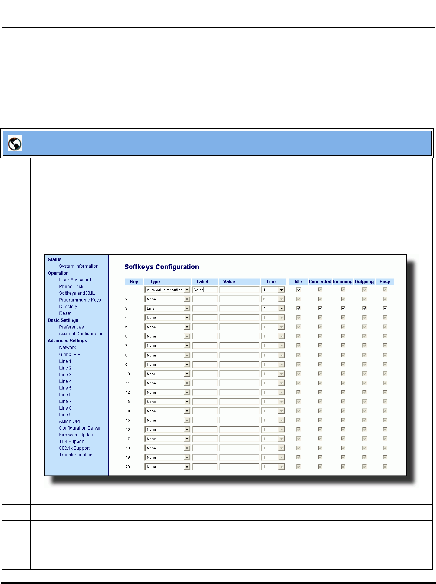
Operational Features
41-001160-03, Rev 00, Releaes 2.4 5-191
Configuring Operational Features
Configuring an ACD Key Using the Aastra Web UI
Use the following procedure to configure an ACD softkey, programmable key, or
expansion module key using the Aastra Web UI. This procedure uses the 6755i IP
phone as an example.
Aastra Web UI
1 Click on Operation->Softkeys and XML
or
Click on Operation->Programmable Keys
or
Click on Operation->Expansion Module <N>.
Depending on your phone-model, the key configuration screen displays. The 6757i Key Screen is
shown as an example.
2 In the “Type” field, select Auto Call Distribution.
3 In the “Label” field, specify a name for this ACD softkey. The Label helps identify which queue you
are subscribing to when you login. (This field does not apply to the 6753i and the 9143i.)
For example: Sales
Draft 1
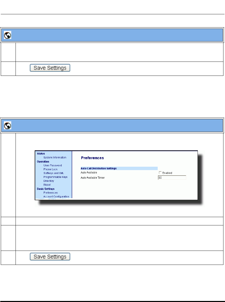
Operational Features
5-192 41-001160-03, Rev 00, Releaes 2.4
IP Phone Administrator Guide
Configuring the ACD Auto-Available Timer Using the Aastra Web UI
Use the following procedure to configure an ACD auto-available timer using the
Aastra Web UI.
4 In the “Line” field, select the line which the IP phone uses to subscribe to the queue.
For example: Line 1
5 Click to save your changes.
Aastra Web UI
1 Click on Basic Settings->Preferences->Auto Call Distribution Settings.
2 In the “Auto Available” check-box, click Enabled.
3 In the “Auto Available Timer” field, specify the length of time (in seconds) before the IP phone
state is automatically reset to “available.” Valid values are 0 to 120 seconds. Default is 60.
For example: 60
4 Click to save your changes.
Aastra Web UI
Draft 1

Operational Features
41-001160-03, Rev 00, Releaes 2.4 5-193
Configuring Operational Features
Using the ACD Feature on your IP Phone
The ACD feature allows you to login to a phone queue in order to receive
distributed calls on your IP phone. To login to a phone queue, your system
administrator must preconfigure an ACD softkey or programmable key on your
Aastra IP phone.
For models 9480i, 9480i CT, 6755i, 6757i, 6757i CT, the ACD softkey is labeled
according to your network requirements. Check with your administrator to verify
the label assigned to the ACD softkey on your IP phone. The label usually
describes which phone queue you are accessing when you press the ACD softkey.
For example, suppose the administrator wants to configure an ACD softkey to
allow an IP phone user to log into the Customer Support phone queue. The
administrator assigns the label “Support” to the softkey, so it is easily
recognizable to the IP phone user. When the IP phone user wants to subscribe to
the Customer Support queue, the user presses the Support key and can log in.
Once logged in to the queue, you can make himself “available” or “unavailable”
to take calls by pressing the Available/Unavailable key on the phone UI. The
server monitors your IP phone status. When you set the IP phone to “available,”
the server begins distributing calls to your phone. When you set the IP phone to
“unavailable,” the server temporarily stops distributing calls to your phone.
The icon that appears next to the ACD softkey or programmable key on the IP
Phone UI reflects your current status. In the example shown below, the icon
shows the current status of this IP phone user as “logged off.”
Mon Jan 2 10:37am
L1
Support
Services
Dir
Callers
Icom
o
ACD softkey
for this example
Draft 1
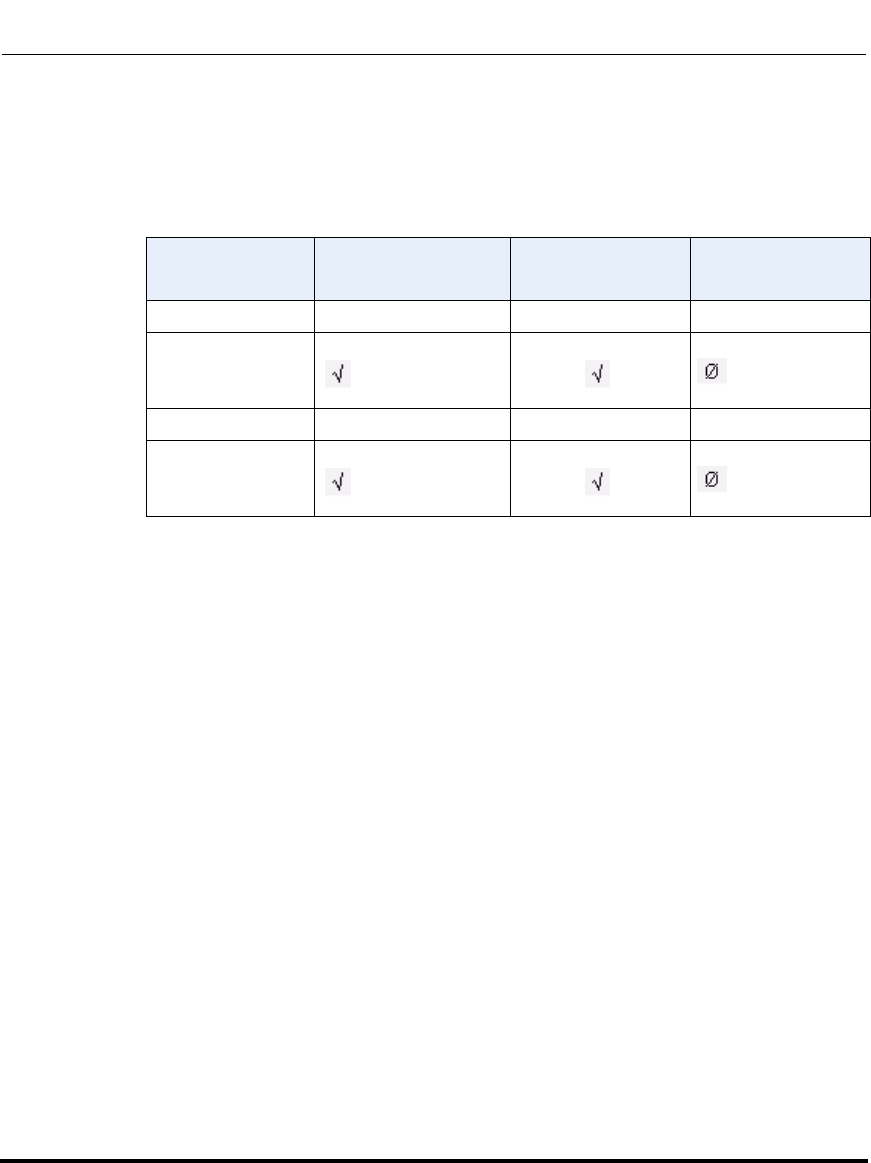
Operational Features
5-194 41-001160-03, Rev 00, Releaes 2.4
IP Phone Administrator Guide
This icon changes when you log on to the phone queue and are available to take
calls. The icon changes again when you are busy with an active call. The table
below describes the meaning of the LED, and each icon, as they may appear on
your IP phone:
Phone Model Status: Logged In
and Available Status: Unavailable Logged Out
9143i Solid Red LED Blinking red LED No LED
9480i, 9480i CT Solid Red LED
icon Blinking Red LED
Blinking icon No LED
icon
6753i Solid Red LED Blinking red LED No LED
6755i, 6757i, 6757i
CT Solid Red LED
icon Blinking Red LED
Blinking icon No LED
icon
Draft 1
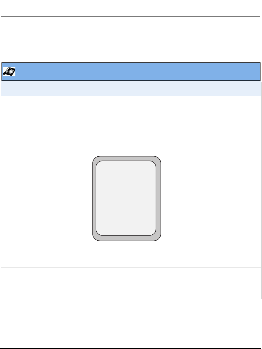
Operational Features
41-001160-03, Rev 00, Releaes 2.4 5-195
Configuring Operational Features
Logging In to a Phone Queue (9480i, 9480i CT, 6755i, 6757i, 6757i CT)
Use the following procedure to log into a phone queue from your Aastra IP phone.
Aastra IP Phone UI
Step Action
1 Press the ACD softkey on your IP phone.
Note: Check with your administrator to verify the label assigned to the ACD softkey on your IP
phone.
The login screen (see below) appears. In this example, the ACD softkey accesses the Customer
Support phone queue and is labelled “Support.”
2 To log into the phone queue, use your IP phone keypad to enter the following information:
User ID: The phone number you use to access the queue.
Password: The password you use to access this queue.
ACD: Support
User ID:
Password:
Services
Dir
Callers
Icom
Backspace Log In
Cancel
Draft 1

Operational Features
5-196 41-001160-03, Rev 00, Releaes 2.4
IP Phone Administrator Guide
3 Press the Log In softkey.
You are logged into the phone queue. Once you log in, examine the IP Phone UI, and note the
following information:
• If your IP phone status is set to “available” then the server will begin to distribute phone calls from
this queue to your IP phone.
• If your IP phone status remains “unavailable” after you log in, then you must manually change the
state to “available” in order to start receiving calls.
• To temporarily stop receiving calls, you can switch the IP phone status to “unavailable.”
While you are on a call (or miss a call that has been distributed to your IP phone), your IP phone
status automatically switches to “unavailable.” Your IP phone remains in the unavailable state until
one of the following things occur:
• You use the IP Phone UI to manually switch the IP phone state back to available, or
• The availability “timer” for your IP phone expires. This only occurs if your administrator has
configured an auto-availability timer on your IP phone.
4 To Log out of the queue, press the Log Out softkey. The server no longer distributes phone calls to
your IP phone.
Aastra IP Phone UI
Step Action
Draft 1
Operational Features
41-001160-03, Rev 00, Releaes 2.4 5-197
Configuring Operational Features
Logging In To a Phone Queue (6753i and 9143i)
Use the following procedure to log into a phone queue from your Aastra IP phone.
Aastra IP Phone UI
Step Action
1 Press the ACD programmable key on your IP phone.
2 To login to the phone queue, use your IP phone keypad to enter the following information:
User ID: The phone number you use to access the queue.
Password: The password you use to access this queue.
3Select Login.
You are logged into the phone queue. Once you log in, examine the IP Phone UI, and note the
following information:
• If your IP phone status is set to “available” then the server will begin to distribute phone calls from
this queue to your IP phone.
• If your IP phone status remains “unavailable” after you log in, then you must manually change the
state to “available” in order to start receiving calls.
• To temporarily stop receiving calls, you can switch the IP phone status to “unavailable.”
While you are on a call (or miss a call that has been distributed to your IP phone), your IP phone
status automatically switches to “unavailable.” Your IP phone remains in the unavailable state until
one of the following things occur:
• You use the IP Phone UI to manually switch the IP phone state back to available, or
• The availability “timer” for your IP phone expires. This only occurs if your administrator has
configured an auto-availability timer on your IP phone.
4 To Log out of the queue, select Logout.
The server no longer distributes phone calls to your IP phone.
Draft 1
Operational Features
5-198 41-001160-03, Rev 00, Releaes 2.4
IP Phone Administrator Guide
ACD Subscription Period
On the IP phones, you can set the time period, in seconds, that the IP phone
resubscribes the ACD subscription service after a software/firmware upgrade or
after a reboot of the IP phone.
In the configuration files, you enter the following parameter with a valid value to
set the ACD subscription period:
sip acd subscription period: <value in seconds>
The minimum value for this 120 seconds (2 minutes).
The default is 3600 (1 hour).
Setting this parameter to a value lower than 3600 allows the configured ACD
feature to become active more quickly after a software/firmware upgrade or after
a reboot of the IP phone. If you enter a value lower than 120 for this parameter,
the default value (3600) will be used by the IP phone.
You can configure this feature using the configuration files or the Aastra Web UI.
Configuring ACD Subscription Period
Use the following procedures to configure the ACD subscription period on the IP
phone.
Configuration Files
To configure the ACD subscription period on the IP phones using the configuration files, see Appendix A, the
section, “Advanced SIP Settings” on page A-92.
Draft 1
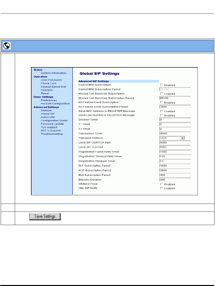
Operational Features
41-001160-03, Rev 00, Releaes 2.4 5-199
Configuring Operational Features
Aastra Web UI
1 Click on Advanced Settings->Global SIP->Advanced SIP Settings.
2 Enter a value, in seconds, from 120 (2 min) to 3600 (1 hour) in the "ACD Subscription Period" field.
3 Click to save your changes.
Draft 1
Operational Features
5-200 41-001160-03, Rev 00, Releaes 2.4
IP Phone Administrator Guide
BLA Subscription Period
The IP Phones include a SIP BLA subscription period parameter that allows an
Administrator to set the amount of time, in seconds, of the BLA subscription
period.
If this parameter is set to zero (0), the phone uses the value specified for the BLA
expiration in the subscribe message received from the server. If no value is
specified in the Subscribe message received from the server, the phone uses the
default value of 300 seconds.
You can configure this parameter using the configuration files or the Aastra Web
UI.
Configuring the BLA Subscription Period
Use the following procedures to configure the BLA Subscription Period.
Configuration Files
To configure the BLA subscription period on the IP phones using the configuration files, see Appendix A, the
section, “Advanced SIP Settings” on page A-92.
Draft 1
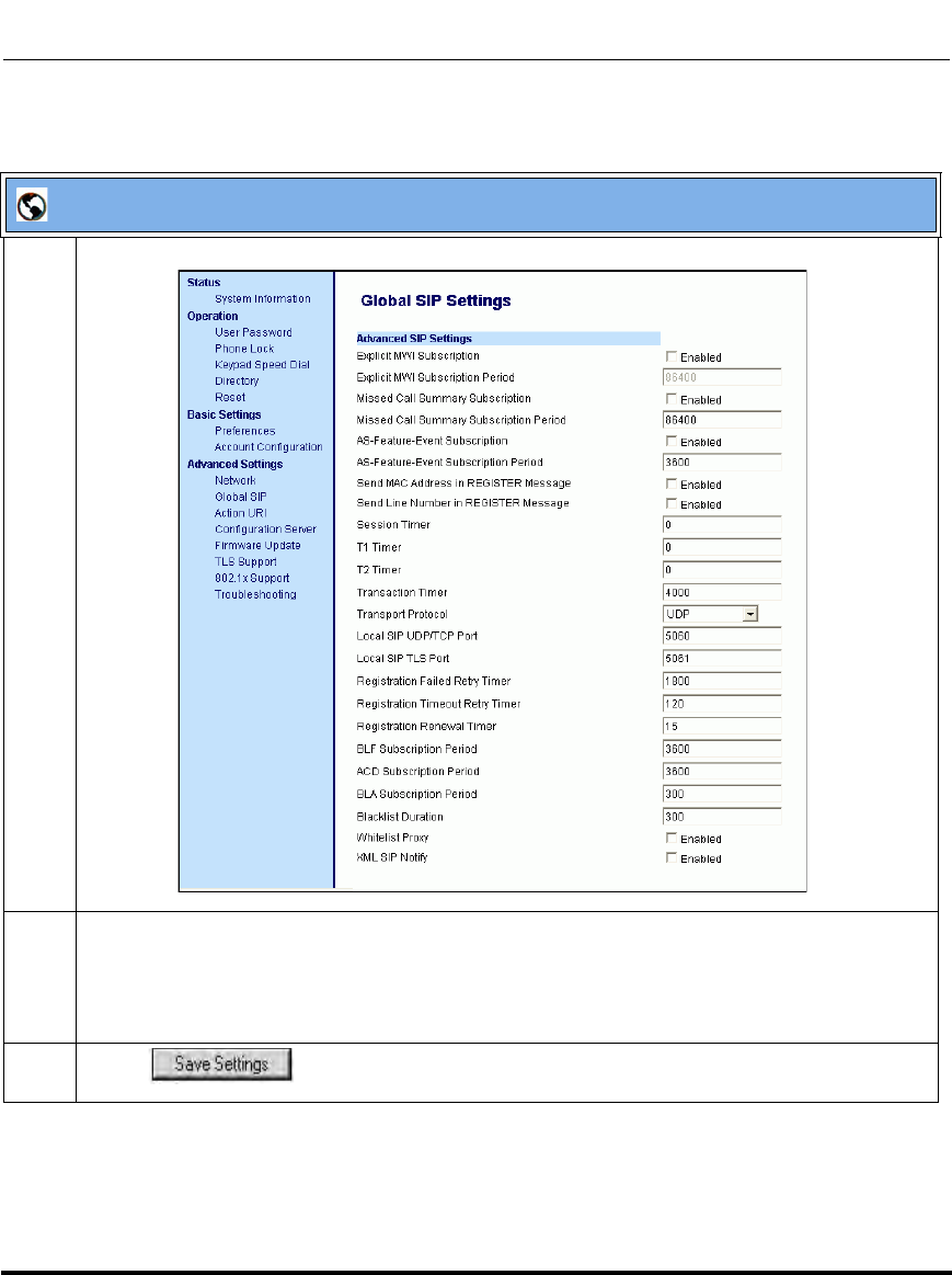
Operational Features
41-001160-03, Rev 00, Releaes 2.4 5-201
Configuring Operational Features
Aastra Web UI
1 Click on Advanced Settings->Global SIP->Advanced SIP Settings.
2 In the “BLA Subscription Period” field, enter a value, in seconds, that the phone waits to receive
a BLA subscribe message from the server. If you specify zero (0), the phone uses the value
specified for the BLA expiration in the subscribe message received from the server. If no value is
specified, the phone uses the default value of 300 seconds. Valid values are 0 to 3700. Default is
300 seconds.
3 Click to save your changes.
Draft 1

Operational Features
5-202 41-001160-03, Rev 00, Releaes 2.4
IP Phone Administrator Guide
Directed Call Pickup/Group Call Pickup (for Sylantro Servers)
Aastra IP phones and any attached Expansion Modules support the Directed Call
Pickup (DCP) and Group Call Pickup (GCP) features.
The Directed Call Pickup/Group Call Pickup feature allows you to intercept - or
pickup - a call on a monitored extension. An Administrator or User can configure
this feature using the Aastra Web UI to create a DCP or GCP softkey on the IP
phone. When you configure a DCP softkey, you specify the extension that you
want to monitor. Then, when the monitored extension receives a call, you press
the DCP softkey to “pickup” (intercept) it. If the monitored extension receives
multiple incoming calls simultaneously, the IP Phone UI displays a list of
incoming calls. You select a call from this list, and are connected to the call.
When you configure a GCP softkey, you specify the ring group that you want to
monitor for incoming calls. For example, suppose an Operator configures a GCP
softkey to monitor incoming calls for a specific ring group (extensions
2200-2210). When an incoming call is received on any of these extensions, the
Operator presses the GCP softkey and is connected to the call. If multiple
incoming calls are received simultaneously, the Operator does the following
actions:
• Presses the GCP softkey. The Operator Phone UI displays the current list of
incoming calls (see below).
• Selects an extension to “pickup” first.
• Presses the Pickup softkey. The Operator is connected to the incoming call.
DCP on line:
= Pickup = Cancel
1. 2201
Select an extension
Press the Pickup
softkey to intercept
the call
Draft 1
Operational Features
41-001160-03, Rev 00, Releaes 2.4 5-203
Configuring Operational Features
Configuring DCP/GCP Using the Configuration Files
(for Sylantro Servers)
Use the following procedures to configure DCP/GCP using the configuration
files.
Configuration Files
To set DCP/GCP in the configuration files, see Appendix A, the section, “Softkey/Programmable Key/
Feature Key/Expansion Module Key Parameters” on page A-192.
Draft 1

Operational Features
5-204 41-001160-03, Rev 00, Releaes 2.4
IP Phone Administrator Guide
Configuring Directed Call Pickup (DCP) Using the Aastra Web UI
(for Sylantro Servers)
Use the following procedure to configure Directed Call Pickup using the Aastra
Draft 1
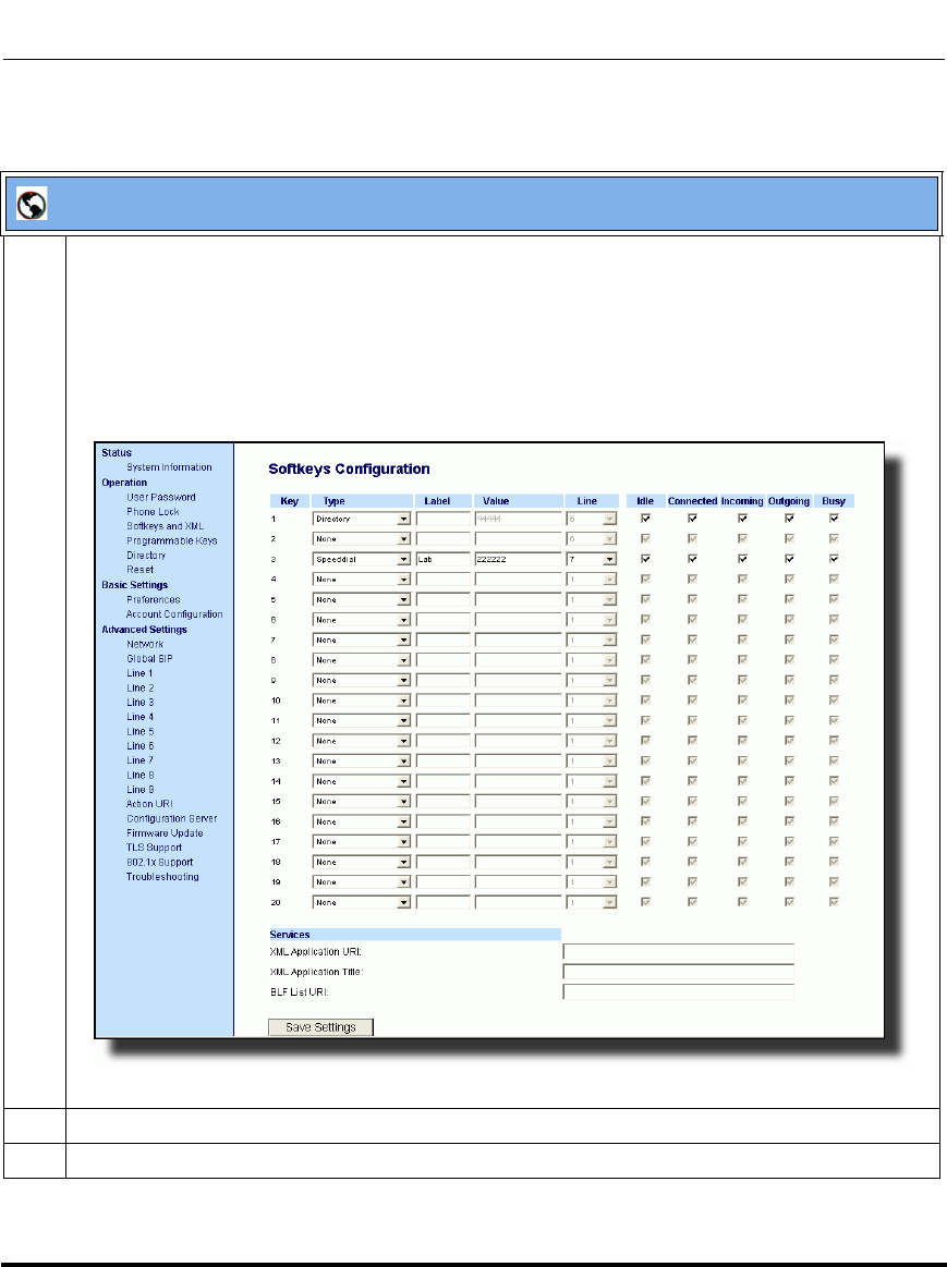
Operational Features
41-001160-03, Rev 00, Releaes 2.4 5-205
Configuring Operational Features
Web UI. This procedure uses the 6757i IP Phone as an example.
Aastra Web UI
1 Click on Operation->Softkeys and XML
or
Click on Operation->Programmable Keys
or
Click on Operation->Expansion Module <N>.
Depending on your phone-model, the key configuration screen displays. The 6755i Key Screen is
shown as an example.
2 Select a key for which to configure Directed Call Pickup.
3 In the “Type” field, select Directed Call Pickup.
Draft 1
Operational Features
5-206 41-001160-03, Rev 00, Releaes 2.4
IP Phone Administrator Guide
4 In the “Label” field, specify a name for this Directed Call Pickup softkey.
For example: DCP2200
5 In the “Value” field, specify the extension you want to intercept when you press this softkey.
For example: 2200
6 Click to save your changes.
Aastra Web UI
Draft 1

Operational Features
41-001160-03, Rev 00, Releaes 2.4 5-207
Configuring Operational Features
Configuring Group Call Pickup (GCP) Using the Aastra Web UI
(for Sylantro Servers)
Use the following procedure to configure Group Call Pickup using the Aastra
Web UI.
Note: A ring group must be configured on the Sylantro Server in order
for a GCP softkey to function.
Draft 1
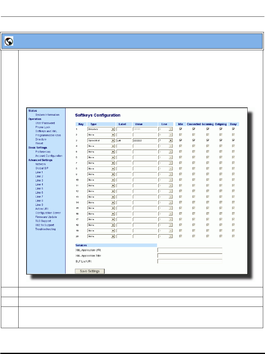
Operational Features
5-208 41-001160-03, Rev 00, Releaes 2.4
IP Phone Administrator Guide
Aastra Web UI
1 Click on Operation->Softkeys and XML
or
Click on Operation->Programmable Keys
or
Click on Operation->Expansion Module <N>.
Depending on your phone-model, the key configuration screen displays. The 6755i Key Screen is
shown as an example.
2 Select a key for which to configure Group Call Pickup.
3 In the “Type” field, select Directed Call Pickup.
4 In the “Label” field, specify a name for this Directed Call Pickup softkey.
For example: GCP_A
Draft 1
Operational Features
41-001160-03, Rev 00, Releaes 2.4 5-209
Configuring Operational Features
Using Directed Call Pickup/Group Call Pickup
Use the following procedure for the DCP/GCP on your phone.
5 In the “Value” field, enter groupcallpickup.
6 Click to save your changes.
Note: Before using the DCP/GCP feature on your phone, you must first
configure the DCP or GCP key. You must identify the extension(s) or
phone number(s) you want to monitor when configuring the key.
IP Phone UI
Step Action
Using Directed Call Pickup (DCP)
1 When the monitored extension receives a call, press the DCP softkey to pick up the call.
2 If the monitored extension receives multiple incoming calls simultaneously, the phone displays a list
of incoming calls.
3Select a call from this list using the UP and DOWN arrow keys.
The call is answered.
Using Group Call Pickup (GCP)
1 When any of the monitored group of extensions receives a call, press the GCP softkey to pick up the
call.
The call is answered.
Aastra Web UI
Draft 1
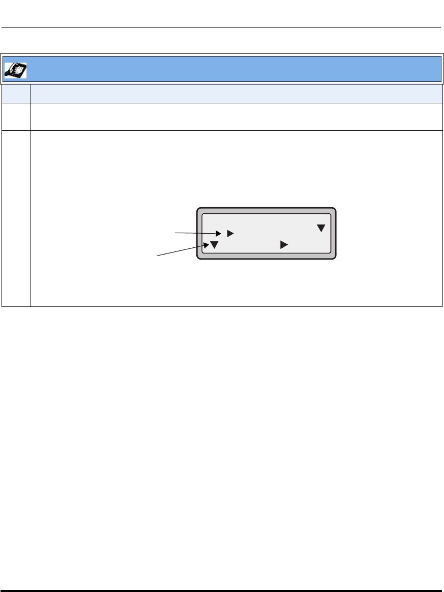
Operational Features
5-210 41-001160-03, Rev 00, Releaes 2.4
IP Phone Administrator Guide
2 If the monitored extension receives multiple incoming calls simultaneously, the phone displays a list
of incoming calls.
3 Select a call from this list using the UP and DOWN arrow keys.
Press the "Pickup" softkey to answer the call you selected.
IP Phone UI
Step Action
Select an extension
Press the Pickup
key to answer
the call
DCP on line:
= Pickup = Cancel
1. 2201
Draft 1

Operational Features
41-001160-03, Rev 00, Releaes 2.4 5-211
Configuring Operational Features
Do Not Disturb (DND)
The IP phones have a feature you can enable called "Do not Disturb (DND). An
Administrator or User can set “do not disturb” based on the accounts on the phone
(all accounts or a specific account). You can set specific modes for the way you
want the phone to handle DND. The three modes you can set on the phone for
DND are:
• Account
• Phone
•Custom
DND Account-Based Configuration
An Administrator or User can configure DND on the phone-side by setting a
mode for the phone to use (account, phone, or custom). Once the mode is set,
you can use the IP Phone UI to use the DND feature.
Notes:
1. If there is only one account configured on the phone, then the
mode setting is ignored and the phone behaves as if the mode was set
to “Phone”.
2. You must configure a DND key on the phone to be able to use
this feature via the phone’s keypad.
Draft 1
Operational Features
5-212 41-001160-03, Rev 00, Releaes 2.4
IP Phone Administrator Guide
The following describes the DND key behavior for each DND mode.
•Account - DND key toggles the account in focus on the IP Phone UI, to ON
or OFF if DND enabled for that account.
•Phone - DND key toggles all accounts on the phone to ON or OFF.
•Custom - DND key displays custom screens on the IP Phone UI. User can
select whether to enable/disable DND per account, enable DND on all
accounts, or disable DND on all accounts.
The following table describes the DND key and Message Waiting Indicator
(MWI) LEDs when you enable DND on the IP Phone.
You can configure the DND softkey and the DND mode (Account, Phone,
Custom) using the configuration files or the Aastra Web UI. Once you configure
DND, you can access the DND screen on the IP Phone UI.
Important Notes
• In the Aastra Web UI, the “Account Configuration” page replaces the
previous “Call Forward Settings” page.
• In the IP Phone UI, the new DND key feature now has new menu screens.
• If you make changes to the configuration for DND via the IP Phone UI,
you must refresh the Aastra Web UI screen to see the changes.
Softkey LED Behavior
for All Modes MWI LED Behavior
for All Modes
DND key LED RED if current account in
focus has DND ON.
DND key LED OFF when current account
in focus has DND disabled.
MWI LED ON if current account in focus has
DND ON.
MWI LED OFF if current account in focus
has DND OFF.
Draft 1
Operational Features
41-001160-03, Rev 00, Releaes 2.4 5-213
Configuring Operational Features
Configuring DND Using the Configuration Files
You use the following parameters to configure DND on the IP Phone:
• dnd key mode
• softkeyN type, topsoftkeyN type, prgkeyN type, or expmodX keyN type
• softkeyN states (optional)
Example
The following is an example of configuring the mode for DND in the
configuration files:
dnd key mode: 2
softkey1 type: dnd
softkey1 states: idle connected incoming outgoing busy
In the above example, softkey 1 is configured for DND for line 1 only, with a
“custom” configuration. Pressing softkey 1 displays DND screens for which you
can customize on the phone. For specific screens that display in the IP Phone UI,
see the section, “Using DND Modes via the IP Phone UI” on page 5-217.
Note: If there is no DND key configured or if it is removed, DND is
disabled on the IP Phone.
Configuration Files
To set DND in the configuration files, see Appendix A, the sections:
•“DND Key Mode Settings” on page A-154.
•“Softkey/Programmable Key/Feature Key/Expansion Module Key Parameters” on page A-192.
Draft 1
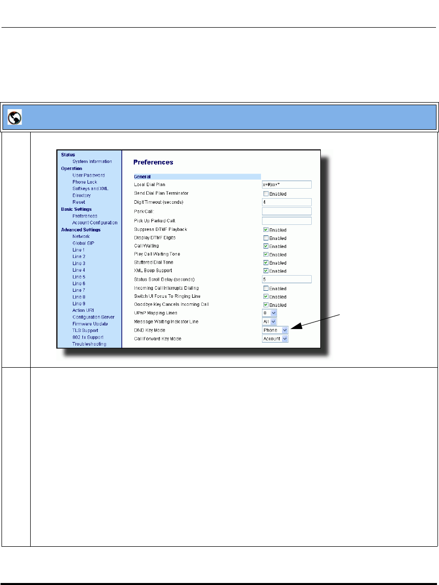
Operational Features
5-214 41-001160-03, Rev 00, Releaes 2.4
IP Phone Administrator Guide
Configuring DND Using the Aastra Web UI
Use the following procedure to configure DND mode using the Aastra Web UI:
Aastra Web UI
1 Click on Basic Settings->Preferences->General.
2 In the “DND Key Mode” field, select a “do not disturb” (DND) mode to use on the phone.
Valid values are: Account, Phone, Custom. Default is Phone.
•account Sets DND for a specific account. DND key toggles the account in focus on the
IP Phone UI, to ON or OFF.
•phone Sets DND ON for all accounts on the phone. DND key toggles all accounts on the
phone to ON or OFF.
•custom Sets the phone to display custom screens after pressing the DND key, that list the
account(s) on the phone. The user can select a specific account for DND, turn
DND ON for all accounts, or turn DND OFF for all accounts.
Notes:
1. If there is only one account configured on the phone, then the mode setting is ignored and the
phone behaves as if the mode was set to “Phone”.
2. Using the Aastra Web UI, if you change the DND Key Mode to “phone”, all accounts
synchronize to the current setting of Account 1.
DND Key Mode
Parameter
Draft 1
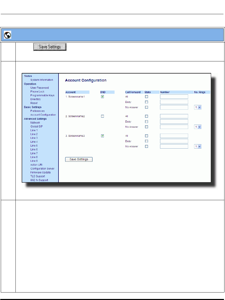
Operational Features
41-001160-03, Rev 00, Releaes 2.4 5-215
Configuring Operational Features
3 Click to save your changes.
The change takes effect immediately without a reboot.
4 Click on Basic Settings->Account Configuration.
5 For each account, enable DND by placing a check mark in the box. Disable DND by unchecking the
box.
Notes:
1. If you selected “Account” or “Custom” mode in step 2, you can enable/disable each account or
all accounts as applicable.
If you selected “Phone” mode, the first account allows you to change the DND status for all accounts.
2. Number and name of accounts that display to this screen are dependant on the number and
name of accounts configured on the phone. In the screen in step 4, Screenname1 is configured on
Line 1, Screenname2 is configured on Line 2, and Screenname3 is configured on Line 3. The name
for the account is dependant on the name specified for the “Screen Name” parameter at the path
Advanced Settings->LineN. If you do not specify a value for the “Screen Name” parameter, the
account name is based on the “Phone Number” parameter at the path Advanced Settings->LineN.
If neither the “Screen Name” nor the “Phone Number” parameters are specified, the account name
shows “1”, “2”, “3”, etc. only.
Aastra Web UI
Draft 1
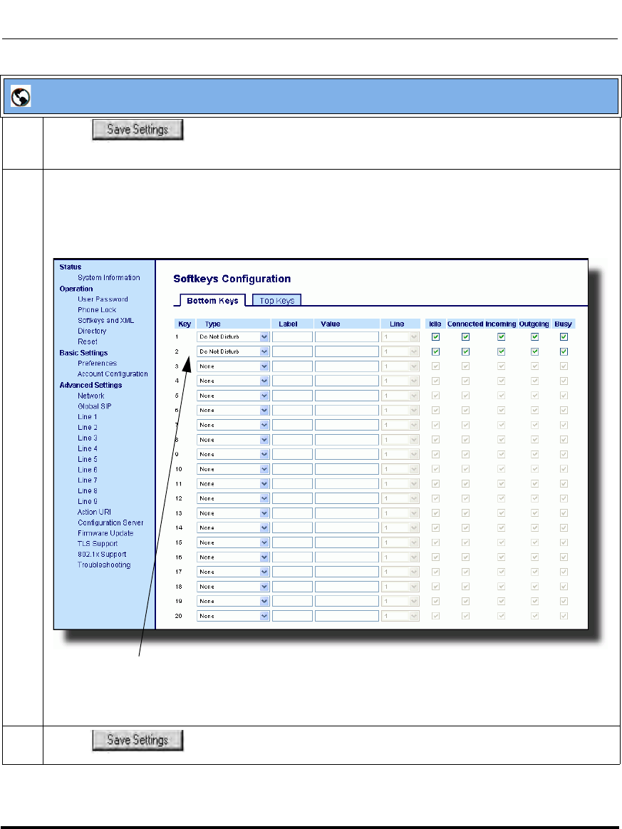
Operational Features
5-216 41-001160-03, Rev 00, Releaes 2.4
IP Phone Administrator Guide
6 Click to save your changes.
The change takes effect immediately without a reboot.
7 Click on Operation->Softkeys and XML;
or
Click on Operation->Programmable Keys;
or
Click on Operation->Expansion Module.
Note: If there is no DND key configured or if it is removed, DND is disabled on the IP Phone.
8 Click to save your changes.
Aastra Web UI
Softkeys 1 and 2 configured for DND
Draft 1
Operational Features
41-001160-03, Rev 00, Releaes 2.4 5-217
Configuring Operational Features
Using DND Modes via the IP Phone UI
If you add a DND key using the configuration files or the Aastra Web UI, you can
toggle the DND state using the IP Phone UI. Use the following procedure to
enable/disable DND on the IP Phone.
The following procedure assumes you have already configured a DND key AND
assumes there are three accounts configured on the phone.
Notes:
1. If there is no DND key configured or if it is removed, DND is
disabled on the IP Phone.
2. If there is only one account configured on the phone, then the
mode setting is ignored and the phone behaves as if the mode was set
to “Phone”.
3. Using the Aastra Web UI, if you change the DND key mode to
“phone”, all accounts synchronize to the current setting of Account 1.
Draft 1
Operational Features
5-218 41-001160-03, Rev 00, Releaes 2.4
IP Phone Administrator Guide
.
Aastra IP Phone UI
Step Action
DND in Account Mode
On the 9143i, 6751i and 6753i:
With the account in focus on the IP Phone UI, press the DND key to toggle DND ON or OFF for the
account. Use the RIGHT and LEFT arrow keys to scroll through each account.
In the above example, Screenname1, Screenname2, and Screenname3, are three accounts
configured on the phone. Only Screenname1 and 3 have DND ON. Screenname 2 has DND OFF.
On the 9480i, 9480i CT, 6755i, 6757i, and 6757i CT:
With the account in focus on the IP Phone UI, press the DND key to toggle DND ON or OFF for the
account. Use the RIGHT and LEFT arrow keys to scroll through each account.
In the above example, Screenname1, Screenname2, and Screenname3, are three accounts
configured on the phone. Only Screenname1 and 3 have DND ON. Screenname 2 has DND OFF.
Screenname1
DND On
Jan 1 12:96
1Screenname2
Jan 1 12:96
2
Screenname3
Jan 1 12:96
3
DND On
Tues Jan1 10:00am
Services
Dir
Callers
L1
- DND
Screenname1
DND On
Tues Jan1 10:00am
Services
Dir
Callers
L2
- DND
Screenname2
Tues Jan1 10:00am
Services
Dir
Callers
L3
- DND
Screenname3
DND On
Draft 1
Operational Features
41-001160-03, Rev 00, Releaes 2.4 5-219
Configuring Operational Features
DND in Phone Mode
On the 9143i, 6751i and 6753i:
Press the DND key to toggle DND ON or OFF for all accounts on the phone. Toggling to ON enables
DND on all accounts on the phone. Toggling to OFF disables DND on all accounts on the phone. Use
the RIGHT and LEFT arrow keys to scroll through each account.
In the above example, toggling Screenname1 to DND ON, enabled DND for Screenname2 and 3
also.
On the 9480i, 9480i CT, 6755i, 6757i, and 6757i CT:
Press the DND key to toggle DND ON or OFF for all accounts on the phone. Toggling to ON enables
DND on all accounts on the phone. Toggling to OFF disables DND on all accounts on the phone. Use
the RIGHT and LEFT arrow keys to scroll through each account.
In the above example, toggling Screenname1 to DND ON, enabled DND for Screenname2 and 3
also.
Note: Enabling DND in “Phone” mode toggles all accounts on the phone to DND ON.
Aastra IP Phone UI
Step Action
Screenname1
DND On
Jan 1 12:96
1Screenname2
Jan 1 12:96
2
Screenname3
Jan 1 12:96
3
DND On
DND On
Tues Jan1 10:00am
Services
Dir
Callers
L1
- DND
Screenname1
DND On
Tues Jan1 10:00am
Services
Dir
Callers
L2
- DND
Screenname2
Tues Jan1 10:00am
Services
Dir
Callers
L3
- DND
Screenname3
DND OnDND On
Draft 1
Operational Features
5-220 41-001160-03, Rev 00, Releaes 2.4
IP Phone Administrator Guide
DND in Custom Mode
On the 9143i, 6751i and 6753i:
Press the DND key on the phone. The screen displays a list of the accounts on the phone and allows
you to enable/disable a specific account or all accounts. Use the UP and DOWN arrow keys to scroll
through the accounts.
In the above example, Screenname1 and 3 have DND ON as indicated by a checkmark ( 3).
Screenname2 has DND off as indicated by an X. Items 4 and 5 allow you to disable or enable DND
on all accounts, respectively.
You use the CHANGE key to enable or disable DND for a specific account. You use the SET key to
enable/disable DND for all accounts. After making the change, you must press DONE and then
Confirm (#) to save the change. Pressing Cancel (0) cancels the attempted change. The following
screen displays after pressing a DONE key:
Aastra IP Phone UI
Step Action
DND
Done
1. Screenname1
Change
DND
Done
2. Screenname2
Change
X
DND
Done
3. Screenname3
Change
DND
Done
4. All Off
Set
DND
Done
5. All On
Set
Indicates
Indicates
DND On
DND Off
Apply Changes?
0 Cancel
# Confirm
Draft 1
Operational Features
41-001160-03, Rev 00, Releaes 2.4 5-221
Configuring Operational Features
If DND is configured on the phone, the softkey or programmable key switches
DND ON and OFF. If the phone shares a line with other phones, only the phone
that has DND configured is affected.
The second line on the screen of the IP phone shows when DND is configured.
When a call comes in on the line, the caller hears a busy signal or recorded
message, depending on the server configuration.
DND in Custom Mode (continued)
On the 9480i, 9480i CT, 6755i, 6757i, and 6757i CT:
Press the DND key on the phone. The screen displays a list of the accounts on the phone and allows
you to enable/disable a specific account or all accounts. Use the UP and DOWN arrow keys to scroll
through the accounts.
In the above example, Screenname1 and 3 have DND ON as indicated by a checkmark ( 3).
Screenname2 has DND off as indicated by an X. The ALL ON and ALL OFF softkeys allow you to
enable or disable DND on all accounts, respectively.
You use the CHANGE key to enable or disable DND for a specific account selected. After making the
change, you must press DONE to save the change.
Aastra IP Phone UI
Step Action
Indicates
Indicates
DND On
DND Off
Services
Dir
Callers
- Change
- All On
- All Off
1. Screenname1
2. Screenname2
3. Screenname3
DND
Cancel -
Done -
X
Draft 1
Operational Features
5-222 41-001160-03, Rev 00, Releaes 2.4
IP Phone Administrator Guide
Bridged Line Appearance (BLA)
A SIP bridge line appearance (BLA) on the IP phones allows multiple devices to
share a single directory address (DA).
For example, people working at a technical support department could be located
in different places. If their desktop phones are configured for BLA DA, when
customer calls come in, all the phones with the BLA DA would ring but the call
can only be answered by one of them.
Once the call is answered, the rest of the phones reflect the status of the call. If the
call was put on "hold" by the original recipient, any one from the group can pick
up the call.
You can apply BLA on the IP phones as follows:
•As a single BLA group - One BLA DA is shared among multiple phones.
Only one phone at a time can pick up an incoming call or initiate an outgoing
call on the BLA DA. All phones reflect the usage of the BLA DA. If the call is
put on "hold", any one from the group can pick up the "held" call.
•As a multiple BLA group - On one single phone, multiple BLA DA can be
associated with different line appearances. Every BLA DA is independent
from each other and follows the same rules as "a single BLA group".
•As multiple instances of a BLA DA - A "x-line-id" parameter was defined in
draft-anil-sipping-bla-02.txt to present the incoming call to or place an
outgoing call on the specified line appearance instance. The parameter is
carried in "Alert-Info" header field over the request-URI (INVITE e.g.) or in
the NOTIFY messages to report the status of a dialog.
BLA DA can be configured on a global basis or on a per-line basis on the IP
phones using the Aastra Web UI or the configuration files.
Note: This feature is dependent on the IP telephony system to which the
IP phone is registered and according to draft-anil-sipping-bla-02.txt.
Draft 1
Operational Features
41-001160-03, Rev 00, Releaes 2.4 5-223
Configuring Operational Features
The following table shows the number of lines that can be set to BLA for each
model phone.
Configuring BLA
You can configure BLA on a global or per-line basis using the configuration files
or the Aastra Web UI.
Global BLA
You configure BLA on a global basis in the configuration files using the following
parameters:
sip mode
sip user name
sip bla number
You configure BLA on a global basis in the Aastra Web UI using the following
fields at Advanced Settings->Global SIP->Basic SIP Settings:
•Line Mode
• Phone Number
• BLA Number
IP Phone Model Possible # of BLA
Lines
9143i 9
9480i 9
9480i CT 9
6751i N/A
6753i 9
6755i 9
6757i 9
6757i CT 9
Draft 1

Operational Features
5-224 41-001160-03, Rev 00, Releaes 2.4
IP Phone Administrator Guide
Per-Line BLA
You configure BLA on a per-line basis in the configuration files using the
following parameters:
sip lineN mode
sip lineN username
sip lineN bla number
You configure BLA on a per-line basis in the Aastra Web UI using the following
fields at Advanced Settings->Line 1 thru Line 9:
•Line Mode
• Phone Number
• BLA Number
Sylantro servers and ININ servers require specific configuration methods for
per-line configurations.
For Sylantro Server
When configuring the BLA feature on a per-line basis for a Sylantro server, the
value set for the "sip lineN bla number" parameter shall be the same value set for
the "sip lineN user name" parameter for all the phones in the group. For example,
if sip lineN user name is 1010, you would configure BLA on a per-line basis for
the Sylantro server as follows:
sip line 1 mode: 3
sip line1 user name: 1010 (# for all the phones)
sip line1 bla number: 1010
Draft 1
Operational Features
41-001160-03, Rev 00, Releaes 2.4 5-225
Configuring Operational Features
For ININ Server
When configuring the BLA feature on an ININ server, the value set for the sip
lineN bla number parameter shall be the same value set for the sip lineN user
name parameter without the incremented digit added to the phone #. For example,
if the sip lineN user name for the first phone is 10101, and the sip lineN user name
for the second phone is 10102, etc., you would configure BLA on a per-line basis
for the ININ server as follows:
(# for phone 1 with appearance of phone 3)
sip line1 mode: 3
sip line1 user name: 10101 sip line1 bla number: 1010
(# for phone 2 with appearance of phone 3)
sip line1 mode: 3
sip line1 user name: 10102
sip line1 bla number: 1010
(# for phone 3)
sip line1 mode: 3
sip line1 user name: 1010
sip line1 bla number: 1010
Use the following procedures to configure BLA on the IP phone.
Configuring Global BLA
Configuring Per-Line BLA
Note: The original phone number which has the bridged line appearance
on other phones, will have the "sip lineN user name" parameter the same
as the "sip lineN bla number" (1010 in the above example on Phone 3).
Configuration Files
For specific global parameters you can set in the configuration files, see Appendix A, the section,
“SIP Basic, Global Settings” on page A-67.
Configuration Files
For specific per-line parameters you can set in the configuration files, see Appendix A, the section,
“SIP Basic, Per-Line Settings” on page A-76.
Draft 1
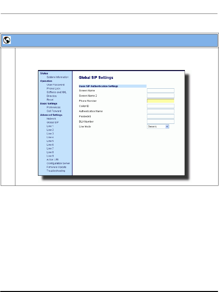
Operational Features
5-226 41-001160-03, Rev 00, Releaes 2.4
IP Phone Administrator Guide
Aastra Web UI
1For global configuration of BLA:
Click on Advanced Settings->Global SIP->Basic SIP Authentication Settings.
Draft 1
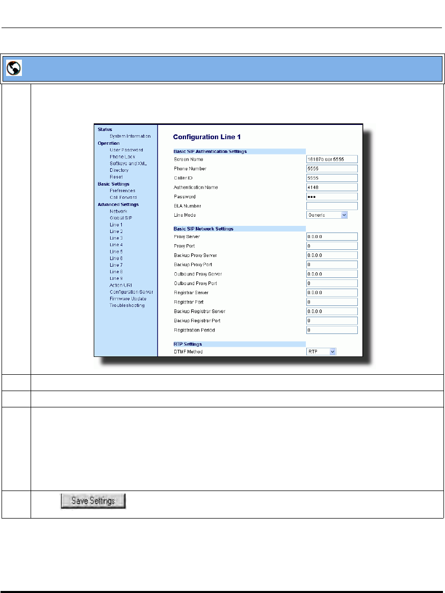
Operational Features
41-001160-03, Rev 00, Releaes 2.4 5-227
Configuring Operational Features
For per-line configuration of BLA:
Click on Advanced Settings->Line N (1-9).
In the "Line Mode" field, select the BLA option.
2 In the "Phone Number" field, enter the phone number of the IP phone.
3For global configuration of BLA:
In the "BLA Number" field, enter the Bridge Line Appearance (BLA) number to be shared across all
IP phones.
For per-line configuration of BLA:
In the "BLA Number" field, enter the Bridge Line Appearance (BLA) number to be shared on a
specific line.
4 Click to save your changes.
Aastra Web UI
Draft 1

BLA Subscription Period
The phones include a SIP BLA subscription period parameter that allows an
Administrator to set the amount of time, in seconds, of the BLA subscription
period.
Reference
For more information about setting the BLA Subscription Period, see the section,
“BLA Subscription Period” on page 5-200.
Using a BLA Line on the IP Phone
If you have either a global or per-line BLA configuration, and you want to share a
call on the line with a BLA group, you need to press the Hold button before
sharing the call with the group.
For example, if line 1 is configured for BLA, and you pick up a call on line 1, you
must press the Hold button to share the call with the BLA group.
If you pick up a call on line 1 configured for BLA, and another call comes in on
line 2, you can pick up line 2 without putting line 1 on hold. The line 1 call will
be on hold automatically; however it is on hold locally only. The line 1 call
cannot be shared with the BLA group.
Note: The Hold button must be pressed for a call on a BLA line to be
shared with the BLA group.
Draft 1

Operational Features
41-001160-03, Rev 00, Releaes 2.4 5-229
Configuring Operational Features
BLA Support for Third Party Registration
BLA allows an Address Of Record (AOR) to be assigned onto different line
appearances for a group of SIP user agents (IP phones). When a call is made to
this BLA number, the call is offered to all user agents that have mapping to this
BLA. To support this, the IP phones need to support third party registration for the
BLA along with the registration for its own primary appearance number. If the IP
phone has the primary appearance as a BLA, then there is no need for third party
registration.
When configuring the BLA feature on a per-line basis for third party registration
and subscription, the third party name must be configured using the “sip lineN bla
number” parameter. For third party registration to work effectively, one of the
lines should register as generic with its own username.
For example, Bob has Alice’s appearance on his phone. Bob’s configuration is as
follows:
#line 1 Bob
sip line1 auth name:4082272203
sip line1 password:
sip line1 mode: 0
sip line1 user name:4082272203
sip line1 display name:Bob
sip line1 screen name:Bob
#line 2 Alice
sip line2 auth name:4082272203
sip line2 password:
#BLA mode 3
sip line2 mode: 3
sip line2 user name:4082272203
Draft 1
Operational Features
5-230 41-001160-03, Rev 00, Releaes 2.4
IP Phone Administrator Guide
#Alice phone number
sip line2 bla number:4085582868
sip line2 display name:Alice
sip line2 screen name:Alice
Alice’s configuration is as follows:
#line 1
sip line1 auth name:4085582868
sip line1 password:
sip line1 mode: 3
sip line1 user name:4085582868
sip line1 display name: Alice
sip line1 screen name: Alice
P-Preferred Identity Header for BLA Accounts
The IP Phones support the BLA specification, draft-anil-sipping-bla-02, which
states that the P-Preferrred-Identity header (RFC3325) gets added to the INVITE
message to indicate the Caller-ID that is used for the call.
Note: The P-Preferred-Identity for BLA accounts is also sent for hold/
unhold messages.
Draft 1

Operational Features
41-001160-03, Rev 00, Releaes 2.4 5-231
Configuring Operational Features
BLA Support for Message Waiting Indicator (MWI)
The IP Phones have an option for a Busy Line Appearance (BLA) configured line
to send a SUBSCRIBE SIP message for a Message Waiting Indicator (MWI).
You can configure this feature using the configuration files or the Aastra Web UI.
Limitations
The following are limitations of the BLA Support for MWI feature:
• The phone shows MWI for the first matching identity if more than one line
with different user names has the same BLA account.
• If a normal line has the same user name as the BLA user of another line, the
phone shows MWI only for the normal line.
Use the following procedure to configure BLA support for MWI.
Notes:
1. If you change the setting on this parameter, you must reboot the
phone for it to take affect.
2. Both the “sip explicit mwi subscription” and “sip mwi for bla
account” parameters must be enabled in order for the MWI subscription
for BLA to occur.
3. The MWI re-subscription for the BLA account uses the value set for
the "sip explicit mwi subscription period" parameter to re-subscribe.
4. Whether or not the "sip mwi for bla account" parameter is enabled,
the priority for displaying MWI does not change.
Draft 1
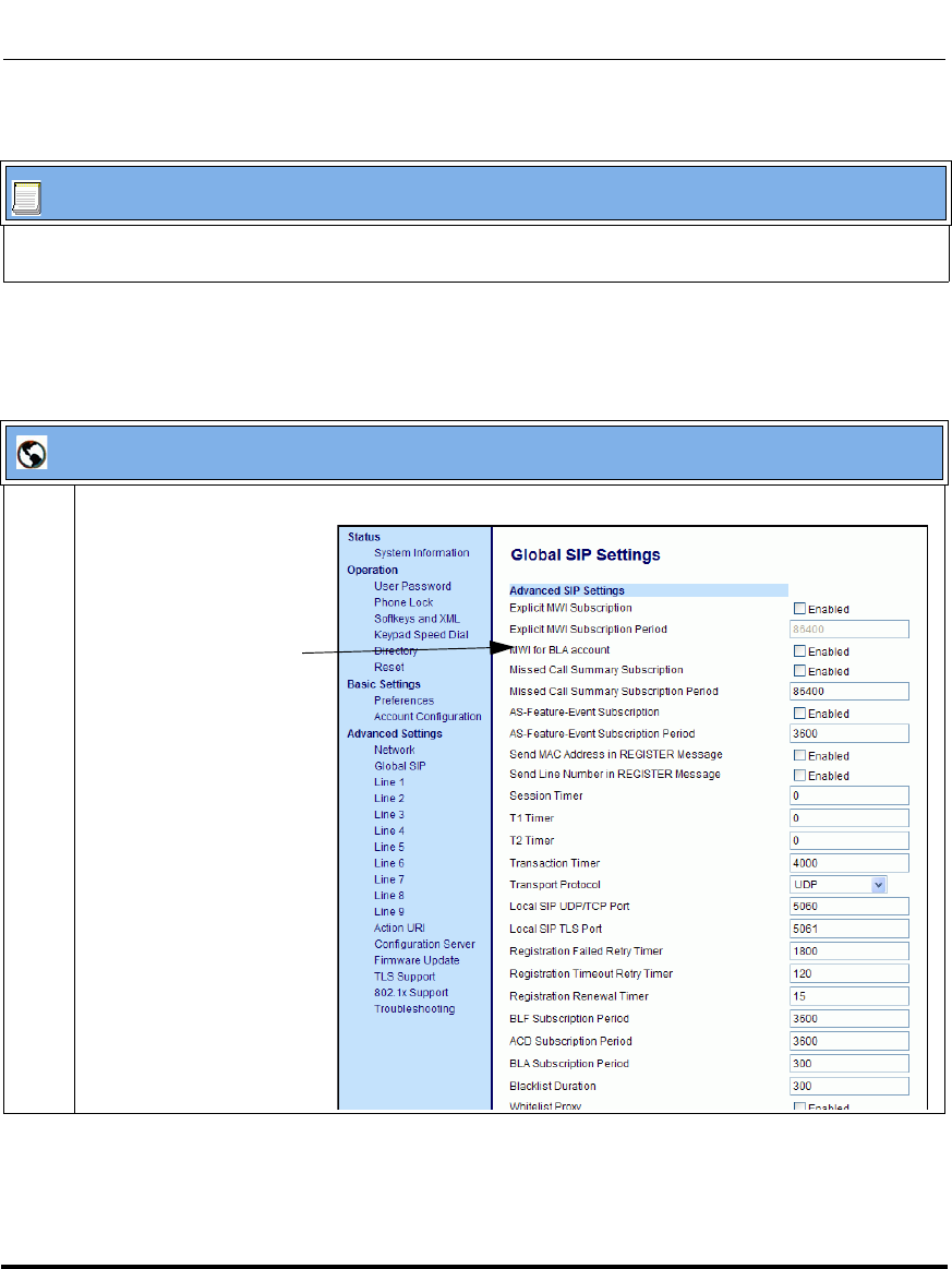
Operational Features
5-232 41-001160-03, Rev 00, Releaes 2.4
IP Phone Administrator Guide
Configuring BLA Support for MWI Using the Configuration Files
Configuring BLA Support for MWI using the Aastra Web UI
Use the following procedure to configure BLA support for MWI.
Configuration Files
For specific parameters you can set in the configuration files, see Appendix A, the section,
“BLA Support for MWI” on page A-87.
Aastra Web UI
1 Click on Advanced Settings->Global SIP->Advanced SIP Settings.
MWI for BLA Account
Parameter
Draft 1
Operational Features
41-001160-03, Rev 00, Releaes 2.4 5-233
Configuring Operational Features
2 The “MWI for BLA Account” field is disabled by default. To enable this feature, place a checkmark
in the “Enabled” box.
Notes:
1. If you change the setting on this parameter, you must reboot the phone for it to take affect.
2. Both the “sip explicit mwi subscription” and “sip mwi for bla account” parameters must be
enabled in order for the MWI subscription for BLA to occur.
3. The MWI re-subscription for the BLA account uses the value set for the "sip explicit mwi
subscription period" parameter to re-subscribe.
4. Whether or not the "sip mwi for bla account" parameter is enabled, the priority for displaying
MWI does not change.
3 Click to save your changes and reboot the phone for the change to take
affect.
Aastra Web UI
Draft 1

Operational Features
5-234 41-001160-03, Rev 00, Releaes 2.4
IP Phone Administrator Guide
Park/Pick Up Key
The IP phones (including the 6757i CT and 9480i CT handsets) have a park and
pickup call feature that allows you to park a call and pickup a call when required.
There are two ways a user or administrator can configure this feature:
• Using a static configuration (globally configures park and pickup)
• Using a programmable configuration (using a key)
The IP phones support the Park/Pickup feature on the Asterisk, BroadWorks,
Sylantro, and ININ PBX servers.
The following paragraph describes the configuration of a park and pickup key on
the IP phone. For information about configuring the park and pickup static
configuration method see “Park Calls/Pick Up Parked Calls” on page 5-59.
Park/Pickup Programmable Configuration (using a key)
The programmable method of configuration creates park and pickup keys
(softkeys, programmable keys, expansion module keys) that you can configure on
the IP phones.
For the 9480i, 9480i CT, 6755i, 6757i, and 6757i CT you can set a key as "Park"
or "Pickup" and then:
• specify a customized label to display on the Phone UI
• specify a value
• specify which line to use
• specify the state of the park and/or pickup keys
For the 9143i and 6753i, you can set a programmable key as "Park" or "Pickup"
and then:
• specify a value
• specify a line to use
Note: The IP phones accept both methods of configuration. However, to
avoid redundancy, Aastra Telecom recommends you configure either a
static configuration or a programmable configuration.
Draft 1

Operational Features
41-001160-03, Rev 00, Releaes 2.4 5-235
Configuring Operational Features
On 9480i/9480i CT and 6757i/6757i CT
On the IP phone UI, the Park/Pickup feature displays the following:
• When a call comes in, and you pickup the handset, the custom label that you
configured for the Park softkey displays on the Phone UI.
• After the call is parked, the label that you configured for the Pickup softkey
displays on other phones in the network. You can then press the "Pickup"
softkey, followed by the applicable value to pickup the call on another phone
in your network.
• On the Model CTs, the customized labels apply to the base unit only. On the
Model CT handsets, pressing Ï displays the default labels of "Park" and
"Pickup".
On 9143i and 6753i
• When a call comes in, and you pickup the handset, you can press the
applicable "Park" programmable key to park the call.
• After the call is parked, you can press the "Pickup" programmable key,
followed by the applicable value to pickup the call.
You can configure a Park and Pickup key configuration using the configuration
files or the Aastra Web UI.
Note: On the 9480i/9480i CT and 6757i/6757i CT, the old softkey
labeled "Pickup" has been renamed to "Answer". This softkey uses the
old functionality - when you pickup the handset, you see a softkey labeled
"Answer". You can then press this key to pick up an incoming call. Do
no confuse this feature with the new Park/Pickup configuration feature.
Draft 1

Operational Features
5-236 41-001160-03, Rev 00, Releaes 2.4
IP Phone Administrator Guide
Configuring Park/Pickup Key Using Configuration Files
In the configuration files, you configure Park/Pickup using the key parameters.
You must specify the "softkeyN value", "prgkeyN value", “topsoftkeyN value“, or
“expmodX keyN value”. The following examples show Park/Pickup
configurations using specific servers.
Model 6757i/6757i CT and 9480i/9480i CT Examples
*When you configure a softkey as "Park", you must configure the state of the softkey as
"connected".
**When you configure a softkey as "Pickup", you can configure the state of the softkey as "idle,
outgoing", or just "idle", or just "outgoing".
Server Park Configuration Pickup Configuration
Asterisk softkeyN type: park
softkeyN label: parkCall
softkeyN value: asterisk;70
softkeyN line: 1
softkeyN states: connected*
softkeyN type: pickup
softkeyN label: pickupCall
softkeyN value: asterisk;70
softkeyN line: 1
softkeyN states: idle, outgoing**
Sylantro softkeyN type: park
softkeyN label: parkCall
softkeyN value: sylantro;*98
softkeyN line: 1
softkeyN states: connected*
softkeyN type: pickup
softkeyN label: pickupCall
softkeyN value: sylantro;*99
softkeyN line: 1
softkeyN states: idle, outgoing**
BroadWorks softkeyN type: park
softkeyN label: parkCall
softkeyN value: broadworks;*68
softkeyN line: 1
softkeyN states: connected*
softkeyN type: pickup
softkeyN label: pickupCall
softkeyN value: broadworks;*88
softkeyN line: 1
softkeyN states: idle, outgoing**
ININ PBX softkeyN type: park
softkeyN label: parkCall
softkeyN value: inin;callpark
softkeyN line: 1
softkeyN states: connected*
softkeyN type: pickup
softkeyN label: pickupCall
softkeyN value: inin;pickup
softkeyN line: 1
softkeyN states: idle, outgoing**
Draft 1
Operational Features
41-001160-03, Rev 00, Releaes 2.4 5-237
Configuring Operational Features
Model 6753i and 9143i Examples
Use the following procedure to configure a Park/Pickup key using the
configuration files.
Server Park Configuration Pickup Configuration
Asterisk prgkeyN type: park
prgkeyN value: asterisk;70
prgkeyN line: 1
prgkeyN type: pickup
prgkeyN value: asterisk;70
prgkeyN line: 1
Sylantro prgkeyN type: park
prgkeyN value: sylantro;*98
prgkeyN line: 1
prgkeyN type: pickup
prgkeyN value: sylantro;*99
prgkeyN line: 1
BroadWorks prgkeyN type: park
prgkeyN value: broadworks;*68
prgkeyN line: 1
prgkeyN type: pickup
prgkeyN value: broadworks;*88
prgkeyN line: 1
ININ PBX prgkeyN type: park
prgkeyN value: inin;callpark
prgkeyN line: 1
prgkeyN type: pickup
prgkeyN value: inin;pickup
prgkeyN line: 1
Note: The 6753i and 9143i do not allow for the configuration of labels
and states.
Configuration Files
For specific parameters you can set in the configuration files, see Appendix A, the section,
“Softkey Settings for 9480i, 9480i CT, 6755i, 6757i, 6757i CT” on page A-193 and “Programmable Key
Settings for 9143i, 6753i, and 6755i” on page A-202.
Draft 1
Operational Features
5-238 41-001160-03, Rev 00, Releaes 2.4
IP Phone Administrator Guide
Configuring a Park/Pickup Key Using Aastra Web UI
On the 6757i/6757i CT and 9480i/9480i CT, you configure a Park and/or Pickup
key at Operation->Softkeys and XML. You enter a key label, and value for a
specific line on the phone. The default state of the Park configuration is
"connected". The default state of the Pickup configuration is "idle, outgoing".
The 6757i CT and 9480i CT handsets use the park/pickup configuration enabled
at Operation->Handset Keys in the Aastra Web UI. If Park or Pickup are
enabled on more than one line on the base unit, the 6757i CT and 9480i CT
handset uses the first programmable configuration.
For example, if line 1 and line 6 are configured for park, the 6757i CT and 9480i
CT handset uses the configuration set for line 1 to park a call.
On the 6753i and 9143i, you configure a Park and/or Pickup key at
Operation->Programmable Keys, and then enter the appropriate value and line.
Park/Pickup Call Server Configuration Values
*Leave "value" fields blank to disable the park and pickup feature.
Use the following procedure to configure the Park/Pickup call feature using the
programmable configuration method and the Aastra Web UI.
Note: Applicable values depend on the server in your network (Asterisk,
BroadWorks, Sylantro, ININ PBX. See the table below for applicable
values.
Server Park Values* Pickup Values*
Aasterisk 70 70
Sylantro *98 *99
BroadWorks *68 *88
ININ PBX callpark pickup
Draft 1
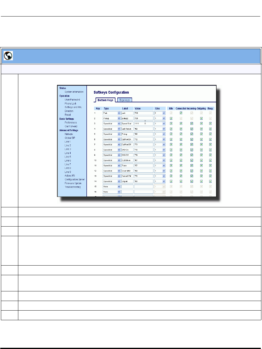
Operational Features
41-001160-03, Rev 00, Releaes 2.4 5-239
Configuring Operational Features
Aastra Web UI
For the 6757i/6757i CT and 9480i/9480i CT:
1 Click on Operation->Softkeys and XML.
2 Pick a softkey to configure for Parking a call.
3 In the "Type" field, select Park.
4 In the "Label" field, enter a label for the Park softkey.
5 In the "Value" field, enter the appropriate value based on the server in your network.
Note: For values to enter in this field, see the table “Park/Pickup Call Server Configuration Values”
on page 5-238.
6 In the "Line" field, select a line for which to apply the Park configuration.
7 The park softkey has a default state of “Connected”.
Leave this state enabled or to disable, uncheck the check box.
8 Pick a softkey to configure for Picking up a call.
9 In the "Type" field, select Pickup.
10 In the "Label" field, enter a label for the Pickup softkey.
Draft 1
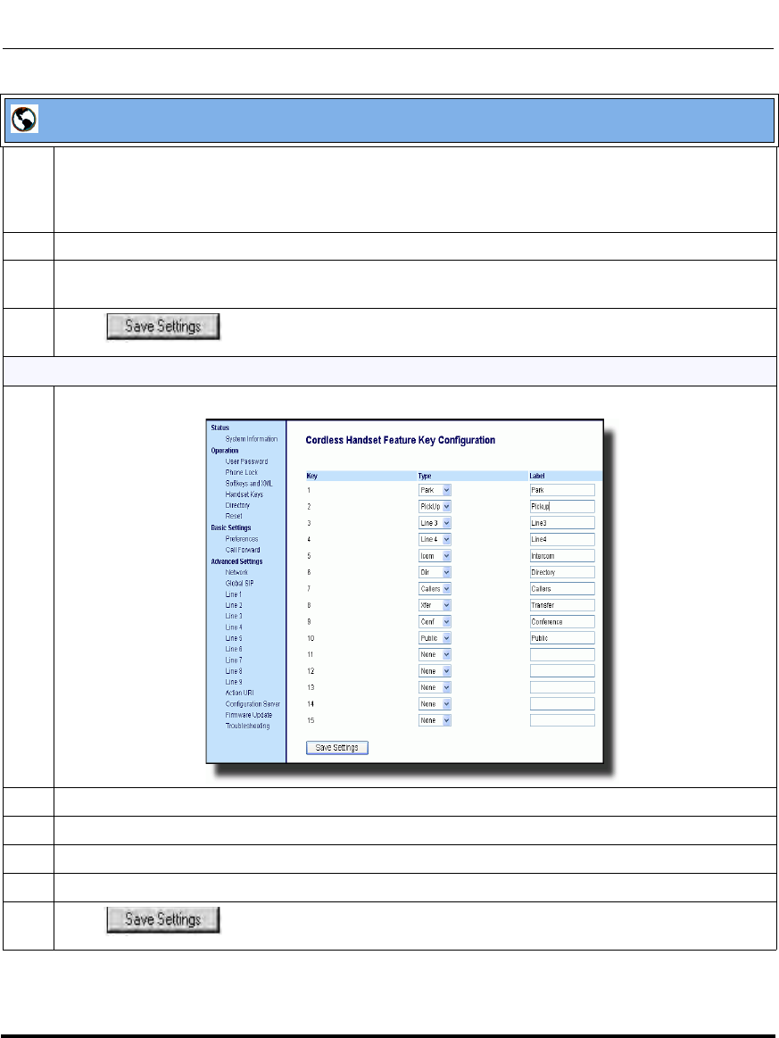
Operational Features
5-240 41-001160-03, Rev 00, Releaes 2.4
IP Phone Administrator Guide
11 In the "Value" field, enter the appropriate value based on the server in your network.
Note: For values to enter in this field, see the table “Park/Pickup Call Server Configuration Values”
on page 5-238.
12 In the "Line" field, select a line for which to apply the Pickup configuration.
13 The pickup softkey has a default state of “Idle” and “Outgoing”.
Leave these states enabled or to disable, uncheck the check boxes.
14 Click to save your changes.
For the 6757i CT and 9480i CT Handset:
1 Click on Operation->Handset Keys.
2 Pick a handset key to configure for parking a call.
3 In the "Key Function" field, select Park.
4 Pick another handset key to configure for picking up a call.
5 In the "Key Function" field, select Pickup.
6 Click to save your changes.
Aastra Web UI
Draft 1
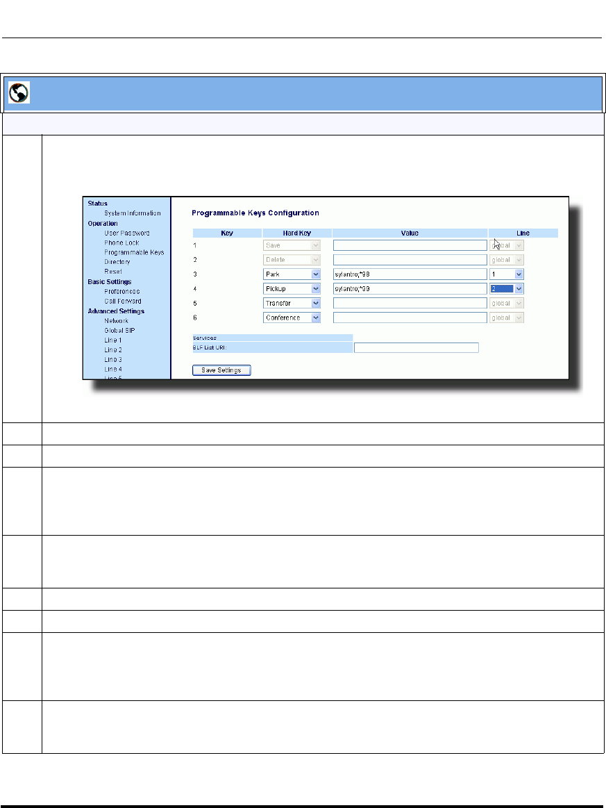
Operational Features
41-001160-03, Rev 00, Releaes 2.4 5-241
Configuring Operational Features
For the 6753i and 9143i:
1 Click on Operation->Programmable Keys.
6753i and 9143i Screen
2 Pick a hard key (from keys 3 through 6) to configure for Parking a call.
3 In the "Hard Key" field, select Park.
4 In the "Value" field, enter the appropriate value based on the server in your network.
Note: For values to enter in this field, see the table “Park/Pickup Call Server Configuration Values”
on page 5-238.
5For the 6753i and 9143i:
In the "Line" field, select a line for which to apply the Park configuration.
6 Pick a hard key to configure for Picking up a call.
7 In the "Hard Key" field, select Pickup.
8 In the "Value" field, enter the appropriate value based on the server in your network.
Note: For values to enter in this field, see the table “Park/Pickup Call Server Configuration Values”
on page 5-238.
9For the 6753i and 9143i:
In the "Line" field, select a line for which to apply the Pickup configuration.
Aastra Web UI
Draft 1
Operational Features
5-242 41-001160-03, Rev 00, Releaes 2.4
IP Phone Administrator Guide
10 Click to save your changes.
You must restart your IP phone for the changes to take affect.
11 Click on Operation->Reset.
12 In the "Restart Phone" field click to restart the IP phone and apply the changes.
Aastra Web UI
Draft 1
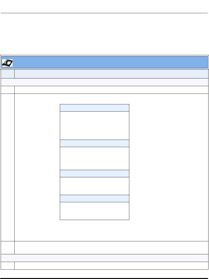
Operational Features
41-001160-03, Rev 00, Releaes 2.4 5-243
Configuring Operational Features
Using the Park Call/Pickup Parked Call Feature
Use the following procedures on the IP phones to park a call and pick up a parked
call.
IP Phone UI
Step Action
Parking a Call
1 While on a live call, press the "Park" softkey.
2 Perform the following for your specific server:
If the call is parked successfully, the response is either a greeting voice confirming that the call was
parked, or a hang up occurs. The parked call party will get music on hold.
3If the call fails, you can pick up the call (using the next procedure) and press the "Park" softkey again
to retry step 2.
Picking up a Parked Call
4 Pick up the handset on the phone.
For Asterisk Server:
- Server announces the
extension number where the call
has been parked. Once the call is
parked, press the y key
to complete parking.
For BroadWorks Server:
- After you hear the greeting from
the CallPark server, enter the
extension where you want to
park the call.
For Sylantro Server:
- Enter the extension number
where you want to park the call,
followed by "#" key.
For ININ Server:
- Enter the extension number
where you want to park the call,
followed by "#" key.
Draft 1
Operational Features
5-244 41-001160-03, Rev 00, Releaes 2.4
IP Phone Administrator Guide
5 Enter the extension number where the call was parked.
6 Press the "Pickup" softkey.
If the call pick up is successful, you are connected with the parked call.
IP Phone UI
Step Action
Draft 1
Operational Features
41-001160-03, Rev 00, Releaes 2.4 5-245
Configuring Operational Features
Last Call Return (lcr) (Sylantro Servers)
Last call return (lcr) allows an administrator or user to configure a "last call
return" function on a softkey or programmable key. This feature is for
Sylantro servers only.
You can configure the “lcr” softkey feature via the configuration files or the
Aastra Web UI.
How it works
If you configure "lcr" on a softkey or programmable key, and a call comes
into your phone, after you are finished with the call and hangup, you can
press the key configured for “lcr” and the phone dials the last call you received.
When you configure an “lcr” softkey, the label “LCR” displays next to that
softkey on the IP phone. When the Sylantro server detects an “lcr” request, it
translates this request and routes the call to the last caller.
Configuring Last Call Return
Use the following procedures to configure LCR on the IP phones.
Configuration Files
For specific last call return (lcr) parameters you can set in the configuration files, see Appendix A, the
section, “Softkey/Programmable Key/Feature Key/Expansion Module Key Parameters” on page A-192.
Draft 1
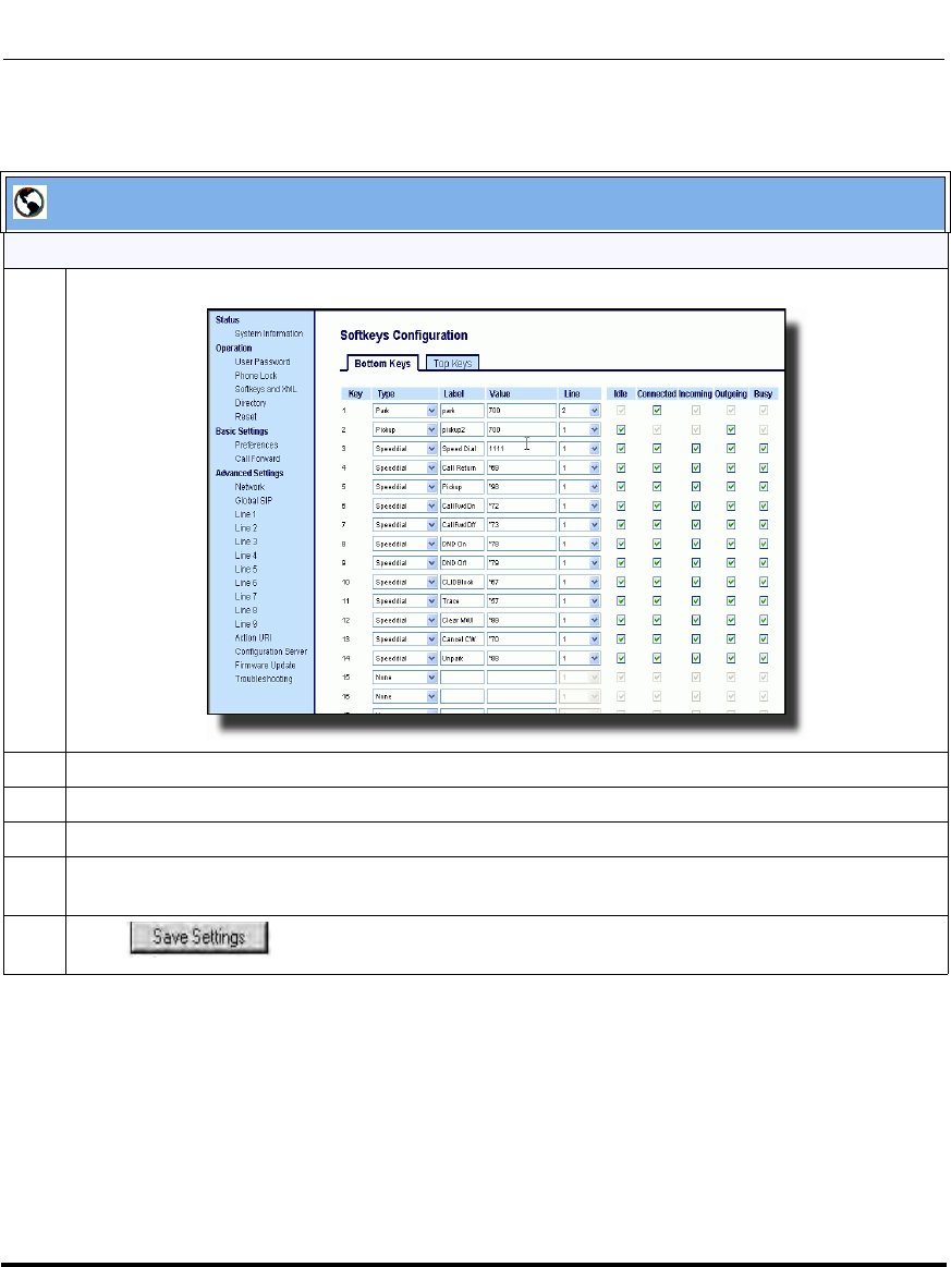
Operational Features
5-246 41-001160-03, Rev 00, Releaes 2.4
IP Phone Administrator Guide
Aastra Web UI
For the 6757i/6757i CT:
1 Click on Operation->Softkeys and XML.
2 Pick a softkey to configure for Last Call Return.
3 In the "Type" field, select lcr.
4 In the "Line" field, select a line for which to apply the last call return configuration.
5 The lcr softkey has a default state of “Idle”, “Connected”, “Incoming”, “Outgoing”.
Leave these states enabled or to disable, uncheck the check boxes as required.
6 Click to save your changes.
Draft 1
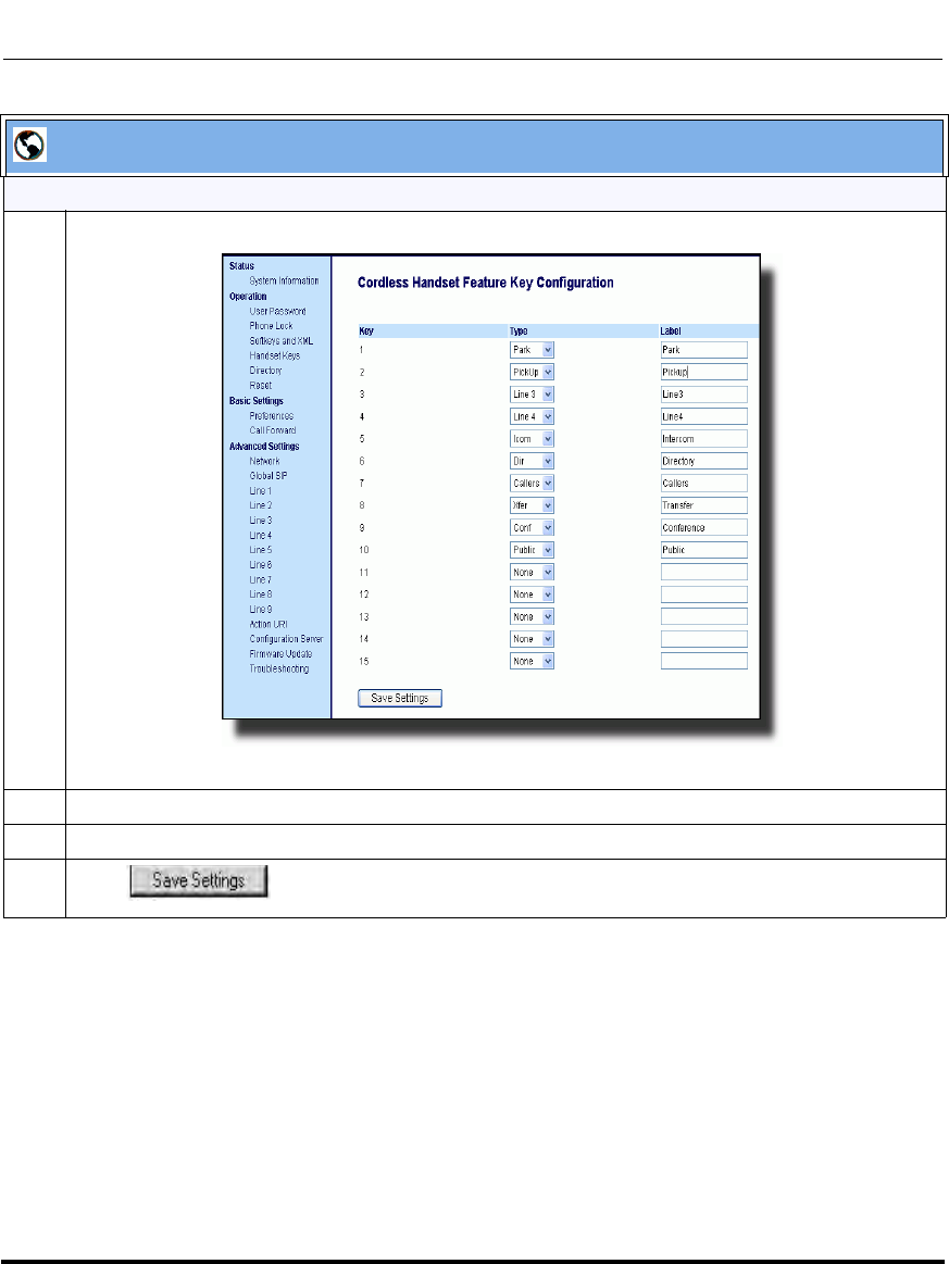
Operational Features
41-001160-03, Rev 00, Releaes 2.4 5-247
Configuring Operational Features
For the 6757i CT Handset:
1 Click on Operation->Handset Keys.
2 Pick a handset key to configure for Last Call Return.
3 In the "Key Function" field, select lcr.
4 Click to save your changes.
Aastra Web UI
Draft 1
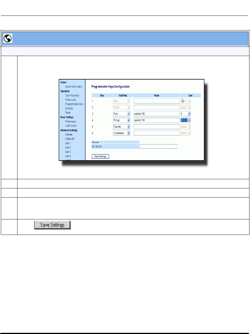
Operational Features
5-248 41-001160-03, Rev 00, Releaes 2.4
IP Phone Administrator Guide
For the 6753i and 9143i
1 Click on Operation->Programmable Keys.
6753i and 9143i Screen
2 Pick a hard key (from keys 3 through 6) to configure for Last Call Return.
3 In the "Type" field, select lcr.
4For the 6753i and 9143i:
In the "Line" field, select a line for which to apply the lcr configuration.
5 Click to save your changes.
Aastra Web UI
Draft 1

Operational Features
41-001160-03, Rev 00, Releaes 2.4 5-249
Configuring Operational Features
Call Forwarding
Call Forward (CFWD) on the IP phone allows incoming calls to be forwarded to
another destination. The phone sends the SIP message to the SIP proxy, which
then forwards the call to the assigned destination.
An Administrator or User can configure CFWD on the phone-side by setting a
mode for the phone to use (Account, Phone, or Custom). Once the mode is set,
you can use the IP Phone UI to use the CFWD feature at Options->Call Forward
or by pressing a configured Call Forward softkey/programmable key/extension
module key.
The following describes the behavior for each CFWD mode.
•Account mode - The account mode allows you to configure CFWD on a per
account basis. Pressing a configured CFWD key applies to the account in
focus.
•Phone mode - The Phone mode allows you to set the same CFWD
configuration for all accounts (All, Busy, and/or No Answer). When you
configure the initial account, the phone applies the configuration to all other
accounts. (In the Aastra Web UI, only the account you configured is enabled.
All other accounts are grayed out but set to the same configuration.) Using the
Aastra Web UI, if you make changes to that initial account, the changes apply
to all accounts on the phone.
•Custom mode - The Custom mode allows you to configure CFWD for a
specific account or all accounts. You can configure a specific mode (All,
Busy, and/or No Answer) for each account independently or all accounts. On
the 9143i, 6751i and 6753i phones, you can set all accounts to ALL On or
ALL Off. On the 9480i, 9480i CT, 6755i, 6757i, and 6757i CT, you can set all
accounts to All On, All Off, or copy the configuration for the account in focus
to all other accounts using a CopytoAll softkey.
You can enable different call forwarding rules/modes independently (for example,
you can set different phone numbers for Busy, All, and NoAns modes and then
turn them on/off individually).
Note: If there is only one account configured on the phone, then the
mode setting is ignored and the phone behaves as if the mode was set
to “Phone”.
Draft 1
Operational Features
5-250 41-001160-03, Rev 00, Releaes 2.4
IP Phone Administrator Guide
The following table describes the key and Message Waiting Indicator (MWI)
LEDs when you enable CFWD on the IP Phone.
You can enable/disable CFWD and set a CFWD key using the configuration files
or the Aastra Web UI. You can set CFWD mode (Account, Phone, Custom)
using the configuration files, Aastra Web UI or IP Phone UI.
Important Notes
• In the configuration files, the “call forward key mode” parameter in the
section, “Configuring Call Forwarding” on page 5-251 is in addition to the
previous call forward parameter (call forward disabled). You can still use the
previous call forwarding parameter if desired in the configuration files.
• In the IP Phone UI, you can access the Call Forwarding features at the path
Options->Call Forward or by pressing a configured CFWD key.
• If you make changes to the configuration for CFWD via the IP Phone UI,
you must refresh the Aastra Web UI screen to see the changes.
Key LED Behavior
for All Modes MWI LED Behavior
for All Modes
CFWD key LED RED if CFWD All, CFWD
Busy, or CFWD No Answer is enabled for
the account in focus.
CFWD key LED OFF if any CFWD mode
is disabled.
MWI LED ON if current account in focus has
CFWD ALL enabled.
MWI LED OFF if CFWD All is disabled.
Draft 1
Operational Features
41-001160-03, Rev 00, Releaes 2.4 5-251
Configuring Operational Features
Configuring Call Forwarding
You use the following parameters to set CFWD on the IP Phone using the
configuration files:
• call forward key mode
• softkeyN type, topsoftkeyN type, prgkeyN type, or expmodX keyN type
• softkeyN states (optional)
Use the following procedures to configure Call Forwarding on the IP phones.
Notes:
1. If there is no CFWD key configured on the phone or it is
removed, you can still set the CFWD modes via the IP Phone UI at the
path Options->Call Forward.
2. If there is only one account configured on the phone, then the
mode setting is ignored and the phone behaves as if the mode was set
to “Phone”.
3. When configuring a CFWD mode (All, Busy, No Answer) for
an account, you must configure a CFWD number for that mode in
order for the mode to be enabled.
Configuration Files
For specific last call forwarding parameters you can set in the configuration files, see Appendix A, the
sections,
•“Priority Alert Settings” on page A-155.
•“Softkey/Programmable Key/Feature Key/Expansion Module Key Parameters” on page A-192.
Draft 1
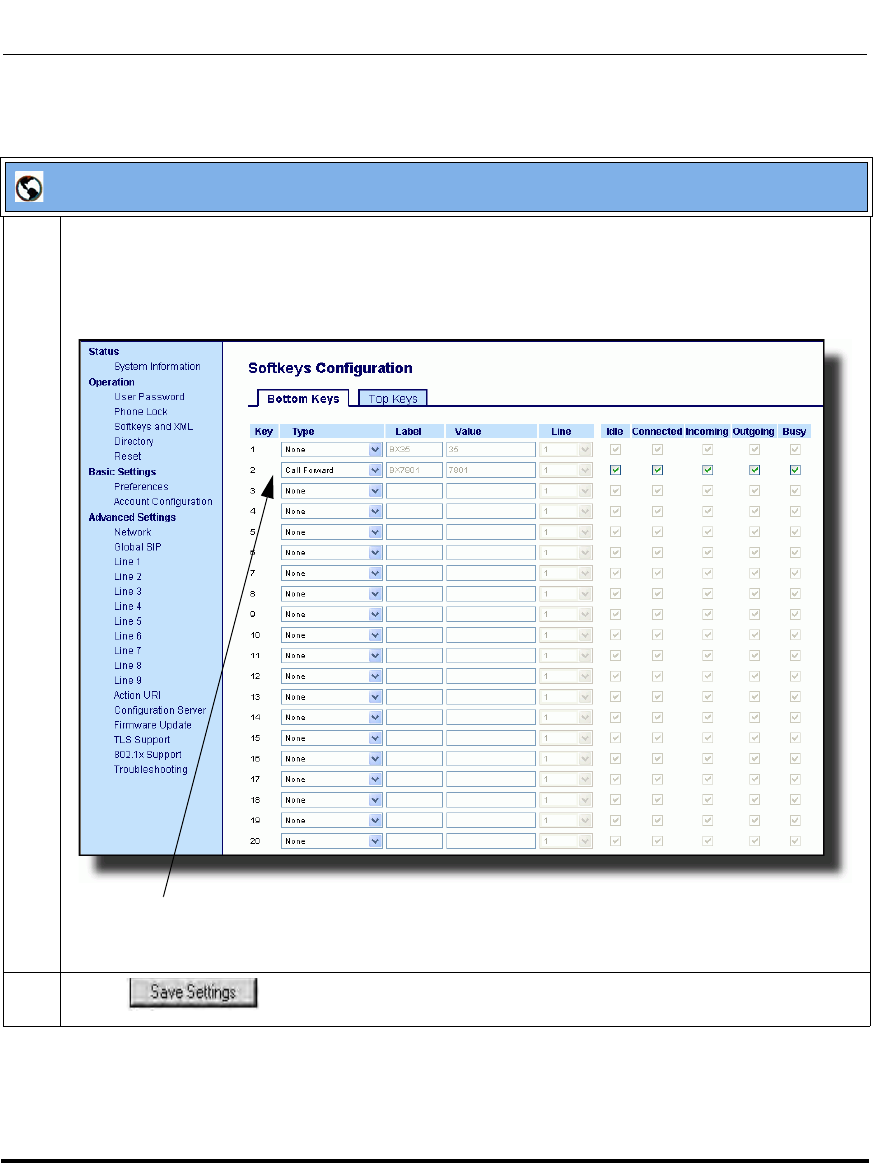
Operational Features
5-252 41-001160-03, Rev 00, Releaes 2.4
IP Phone Administrator Guide
:
Aastra Web UI
1 Click on Operation->Softkeys and XML;
or
Click on Operation->Programmable Keys;
or
Click on Operation->Expansion Module.
2 Click to save your changes.
Softkey 2 configured for CFWD
Draft 1
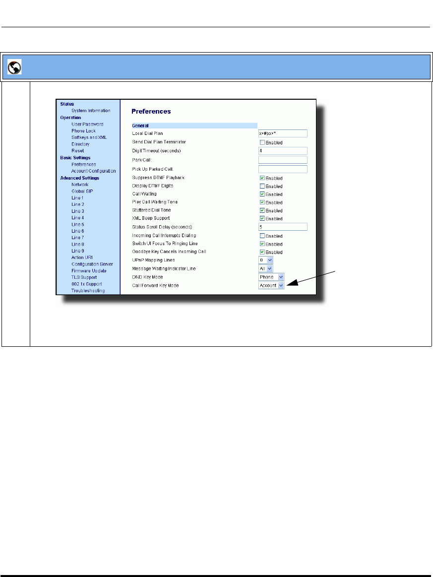
Operational Features
41-001160-03, Rev 00, Releaes 2.4 5-253
Configuring Operational Features
3 Click on Basic Settings->Preferences->General.
Note: If there is no CFWD key configured on the phone or it is removed, you can still set the CFWD
modes via the IP Phone UI at the path Options->Call Forward.
Aastra Web UI
Call Forward
Key Mode
Parameter
Draft 1
Operational Features
5-254 41-001160-03, Rev 00, Releaes 2.4
IP Phone Administrator Guide
4 In the “Call Forward Key Mode” field, select a call forward mode to use on the phone.
Valid values are: Account, Phone, Custom. Default is Account.
•account
The account mode allows you to configure CFWD on a per account basis. Pressing a configured
CFWD key applies to the account in focus.
•phone
The Phone mode allows you to set the same CFWD configuration for all accounts (All, Busy,
and/or No Answer). When you configure the initial account, the phone applies the configuration
to all other accounts. (In the Aastra Web UI, only the account you configured is enabled. All other
accounts are grayed out but set to the same configuration.) Using the Aastra Web UI, if you make
changes to that initial account, the changes apply to all accounts on the phone.
•custom
The Custom mode allows you to configure CFWD for a specific account or all accounts. You can
configure a specific state (All, Busy, and/or No Answer) for each account independently or all
accounts. On the 9143i, 6751i, and 6753i phones, you can set all accounts to ALL On or ALL
Off. On the 9480i, 9480i CT, 6755i, 6757i, and 6757i CT, you can set all accounts to All On, All
Off, or copy the configuration for the account in focus to all other accounts using a CopytoAll
softkey.
Notes:
1. If there is no CFWD key configured on the phone or it is removed, you can still set the CFWD
modes via the IP Phone UI at the path Options->Call Forward.
2. If there is only one account configured on the phone, then the mode setting is ignored and the
phone behaves as if the mode was set to “Phone”.
3. When configuring a CFWD state (All, Busy, No Answer) for an account, you must configure a
CFWD number for that state in order for the state to be enabled.
5 Click to save your changes.
The change takes effect immediately without a reboot.
Aastra Web UI
Draft 1
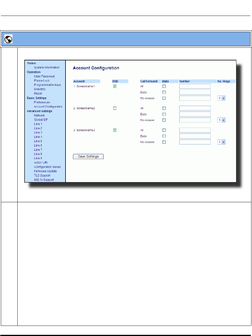
Operational Features
41-001160-03, Rev 00, Releaes 2.4 5-255
Configuring Operational Features
6 Click on Basic Settings->Account Configuration.
7 For each account, enable CFWD state by placing a check mark in one or more of the following
“State” fields:
•All
•Busy
• No Answer
The “All” option forwards all incoming calls for this account to the specified phone number regardless
of the state of the phone. The phone can be in the Busy or No Answer states, or can be in the idle
state. The phone still forwards all calls to the specified number.
The “Busy” option call forwards incoming calls only if the account is in the busy state. The calls are
forwarded to the specified phone number.
The “No Answer” option call forwards incoming calls only if the account rings but is not answered in
the defined number of rings. The call gets forwarded to the specified number.
Note: You can use the “Busy” and “No Answer” states together using different forwarding phone
numbers. If these states are enabled for an account (the “All” state is disabled), and the phone is in
the busy state when a call comes in, the phone can forward the call to the specified phone number
(for example, voicemail). If there is no answer on the phone after the specified number of rings, the
phone can forward the call to a different specified number, such as a cell phone number.
Aastra Web UI
Draft 1
Operational Features
5-256 41-001160-03, Rev 00, Releaes 2.4
IP Phone Administrator Guide
8 For each account, in the “Number” field, enter the phone number for which you want the incoming
calls to forward to if the phone is in the specified state.
If using the “Account” mode or “Custom” mode, you can enter different phone numbers for each
account.
Notes:
1. If you selected “Account” mode in step 4, you can enable/disable each account or all accounts
as applicable. You can enter different phone number for each enabled state.
If you selected “Custom” mode, you can enable/disable each account or all accounts as applicable.
You can enter different phone numbers for each enabled state.
If you selected “Phone” mode, all accounts are set to the same CFWD configuration (All, Busy, and/
or No Answer) as Account 1 on the phone. (In the Aastra Web UI, only Account 1 is enabled. All
other accounts are grayed out but use the same configuration as Account 1.)
Using the Aastra Web UI, if you make changes to Account 1, the changes apply to all accounts on
the phone. Using the IP Phone UI, if you make changes to any other account other then Account 1,
the changes also apply to all accounts on the phone. When enabling a CFWD state, you must specify
a phone number for the phone to CFWD to. The number you specify applies to all accounts of the
same mode.
2. Number and name of accounts that display to this screen are dependant on the number and
name of accounts configured on the phone. In the screen in step 6, Screenname1 is configured on
Line 1, Screenname2 is configured on Line 2, and Screenname3 is configured on Line 3. The name
for the account is dependant on the name specified for the “Screen Name” parameter at the path
Advanced Settings->LineN. If you do not specify a value for the “Screen Name” parameter, the
account name is based on the “Phone Number” parameter at the path Advanced Settings->LineN.
If neither the “Screen Name” nor the “Phone Number” parameters are specified, the account name
shows “1”, “2”, “3”, etc. only.
9 For the No Answer state, in the “No. Rings” field, enter the number of times that the account rings
before forwarding the call to the specified number. Valid values are 1 through 20. Default is 1.
Note: When using the “Account” mode or “Custom” mode, you can enter a different number of rings
for each account. If you use the Aastra Web UI to change the Call Forward Key Mode to “Phone”, all
accounts synchronize to Account 1.
10 Click to save your changes.
The change takes effect immediately without a reboot.
Aastra Web UI
Draft 1
Operational Features
41-001160-03, Rev 00, Releaes 2.4 5-257
Configuring Operational Features
Using CFWD Modes via the IP Phone UI
If you enable/disable CFWD using the configuration files or the Aastra Web UI,
you can use the CFWD screens that display to the IP Phone UI. You can access the
CFWD parameters by pressing a configured CFWD key (if previously
configured) OR by pressing Options->Call Forward on the phone’s front panel.
The following procedure assumes you have already configured a CFWD key
AND assumes there are three accounts configured on the phone.
Notes:
1. If there is no CFWD key configured on the phone or it is
removed, you can still enable CFWD via the IP Phone UI at the path
Options->Call Forward.
2. If there is only one account configured on the phone, then the
mode setting is ignored and the phone behaves as if the mode was set
to “Phone”.
3. Using the Aastra Web UI, if you change the CFWD key mode to
“Phone”, all accounts synchronize to the current setting of Account 1.
Draft 1
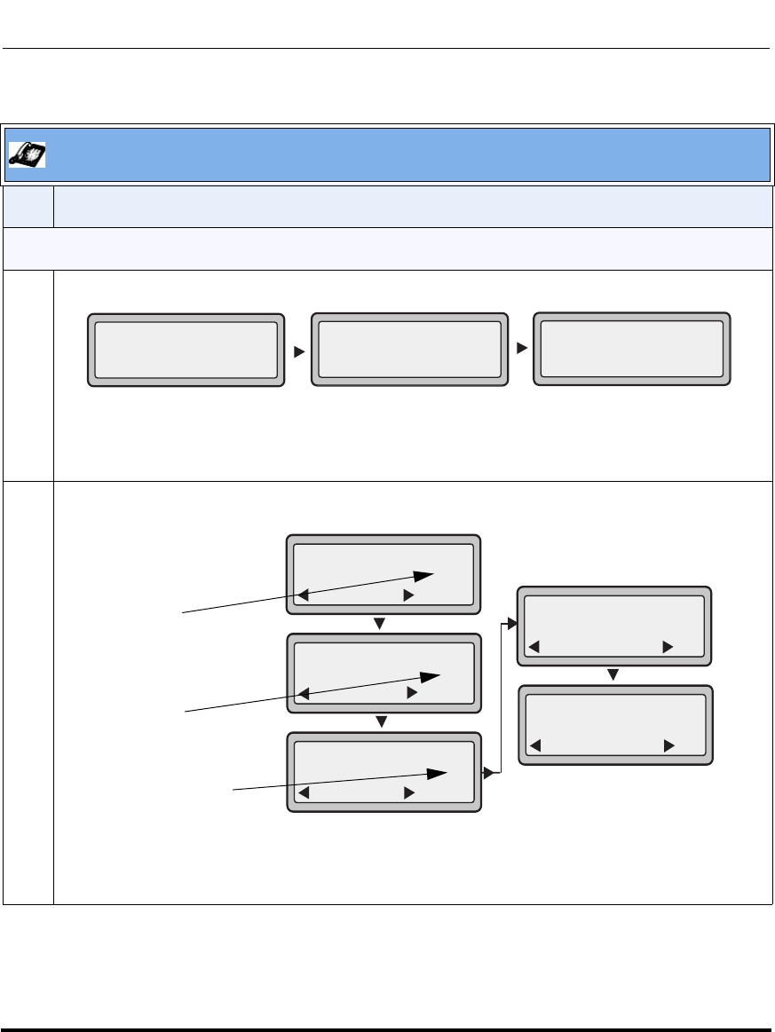
Operational Features
5-258 41-001160-03, Rev 00, Releaes 2.4
IP Phone Administrator Guide
.
Aastra IP Phone UI
Step Action
CFWD in Account Mode (9143i, 6751i, and 6753i)
1Use the RIGHT and LEFT arrow keys to scroll through each account.
In the above example, Screenname1, Screenname2, and Screenname3, are three accounts
configured on the phone. Screenname1 has “CFWD All” enabled, Screenname 2 has CFWD
disabled as indicated by no message displayed, and Screenname3 has “CFWD Busy” enabled.
2 Press the Call Forward key. The Call Forward Mode screen displays. Use the UP and DOWN arrow
keys to scroll through each state type.
In the above example, CFWD All is enabled as indicated by a checkmark ( 3), CFWD Busy is
enabled but no call forward phone number configured as indicated by a !, and CFWD NoAns is
disabled, as indicated by an X.
Screenname1
CFWD All
Jan 1 12:96
1Screenname2
Jan 1 12:96
2Screenname3
Jan 1 12:96
3
CFWD Busy
Indicates
Indicates
CFWD Enabled
CFWD Disabled
Indicates
no CFWD
phone number
configured
Cfwd Mode
Done
1. All
Change
Cfwd Mode
Done
2. Busy
Change
Cfwd Mode
Done
3. NoAns
Change
Cfwd Mode
Done
4. All Off
Set
Cfwd Mode
Done
5. All On
Set
!
X
Draft 1
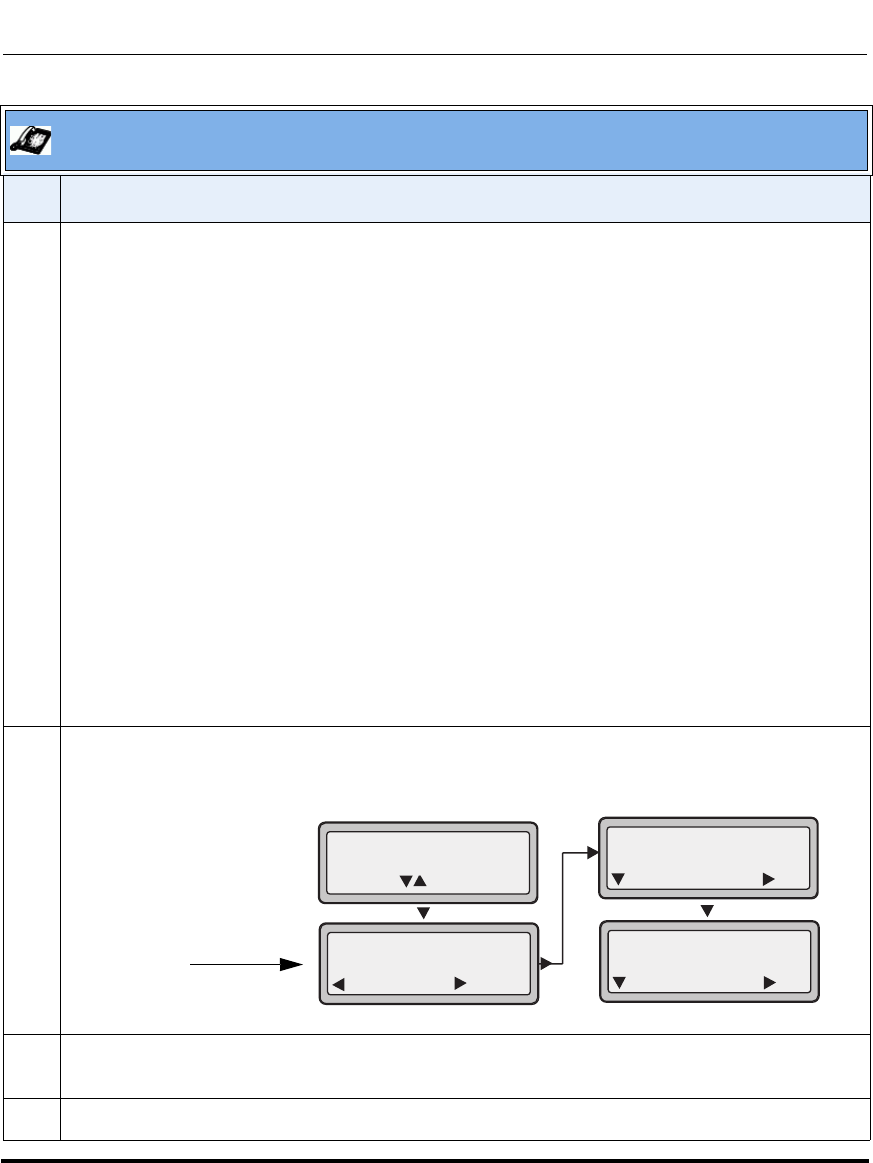
Operational Features
41-001160-03, Rev 00, Releaes 2.4 5-259
Configuring Operational Features
3 Select a state for the account(s) in focus using the UP and DOWN arrow keys.
You can enable/disable any or all of the following states for an account:
•All - Enables CFWD All for an account and forwards all incoming calls for that account, to the
specified number.
•Busy - Enables CFWD Busy for an account and forwards incoming calls to a specified number if
DND has been enabled for that account OR if the account is currently engaged in another call.
•No Answer - Enables CFWD NoAns for an account and forwards incoming calls to a specified
number if the call has not been answered for the specified number of rings.
Note: If CFWD All AND CFWD Busy AND CFWD NoAns are all enabled (and/or if the account has
DND enabled), the CFWD All settings take precedence over CFWD Busy and CFWD NoAns.
You can also use the following keys if required:
All Off - Disables all CFWD states for the current account in focus.
All On - Enables all CFWD states for the current account in focus.
4 Press the CHANGE key for the state you selected in step 3. Scroll to the CFWD State screen. This
displays the current state of the mode you selected. In the following example, the CFWD All state is
ON.
5 Press the CHANGE key in the CFWD State screen. Press NEXT to toggle the state of the CFWD
mode ON or OFF. In the example in Step 4, you press NEXT to change the option to OFF.
6 Press the SET key to save the change.
Aastra IP Phone UI
Step Action
CFWD State
Screen
1. Cfwd All
1. Cfwd State
Done
On
Change
Cfwd State
Next
On
Set
Cfwd State
Next
Off
Set
Use to view
Change
Draft 1
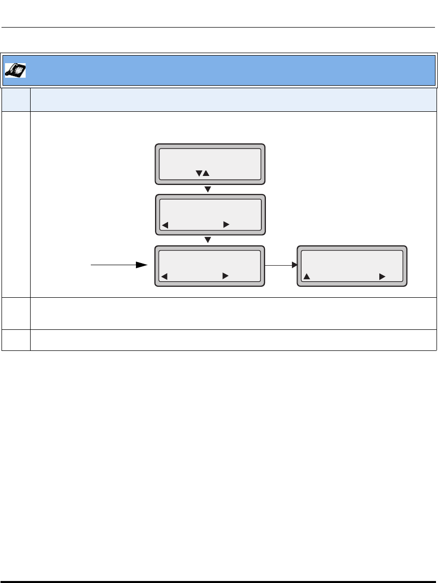
Operational Features
5-260 41-001160-03, Rev 00, Releaes 2.4
IP Phone Administrator Guide
7 In the CFWD State screen, press the DOWN arrow key to scroll to the CFWD Number screen and
press CHANGE.
8 Enter a phone number to apply to the current state in focus. When the phone is in the state you
specified, and a call comes into the phone, it forwards the call to the number you specify.
9 Press SET to save the change.
Aastra IP Phone UI
Step Action
CFWD Number
Screen 2. Cfwd Number
Done Change
Cfwd Number
Cancel
__
Set
Change
1. Cfwd All
1. Cfwd State
Done
On
Change
Use to view
Draft 1
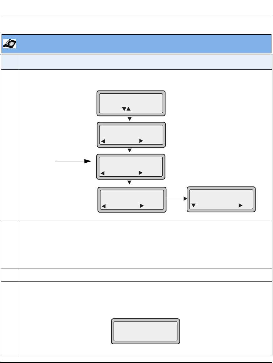
Operational Features
41-001160-03, Rev 00, Releaes 2.4 5-261
Configuring Operational Features
10 For the CFWD No Answer state, In the CFWD Number screen, press the DOWN arrow key to scroll
to the CFWD No. Rings screen and press CHANGE.
11 Press the NEXT key to select the number of rings to apply to the phone for call forwarding incoming
calls. Valid values are 1 to 20. Default is 1.
When the phone receives an incoming call, and call forward is configured on the phone, the phone
rings the number of times you specify in the No. Rings screen, and then forwards the call if there is
no answer.
12 Press SET to save the change.
13 Press DONE to save CFWD All Number, CFWD All State, CFWD Busy Number, CFWD Busy State,
CFWD No Answer Number, CFWD No Answer State, CFWD No Answer Rings.
Each time you press DONE, the following “Apply Changes” screen displays.
Aastra IP Phone UI
Step Action
CFWD No.
Rings Screen 2. Cfwd Number
Done Change
1. Cfwd NoAns
1. Cfwd State
Done
On
Change
Use to view
3. No. Rings
Done Change
No. Rings
1
Change
Next Set
Apply Changes?
0 Cancel
# Confirm
Draft 1

Operational Features
5-262 41-001160-03, Rev 00, Releaes 2.4
IP Phone Administrator Guide
14 Press # to confirm the change(s) each time the “Apply Changes” screen displays.
All changes are saved to the phone.
Aastra IP Phone UI
Step Action
Draft 1
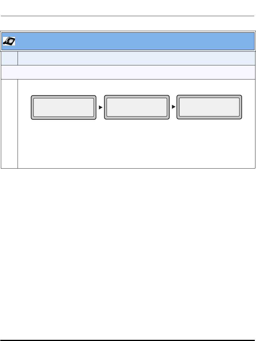
Operational Features
41-001160-03, Rev 00, Releaes 2.4 5-263
Configuring Operational Features
CFWD in Phone Mode (9143i, 6751i, and 6753i)
1Use the RIGHT and LEFT arrow keys to scroll through each account.
In the above example, Screenname1, Screenname2, and Screenname3, are three accounts
configured on the phone. All three accounts have CFWD enabled as indicated by the “CFWD All”
message.
Note: In ”Phone” mode, when you change the call forward configuration for an account, the
change applies to all accounts.
Aastra IP Phone UI
Step Action
Screenname1
CFWD All
Jan 1 12:96
1Screenname2
Jan 1 12:96
2Screenname3
Jan 1 12:96
3
CFWD All
CFWD All
Draft 1
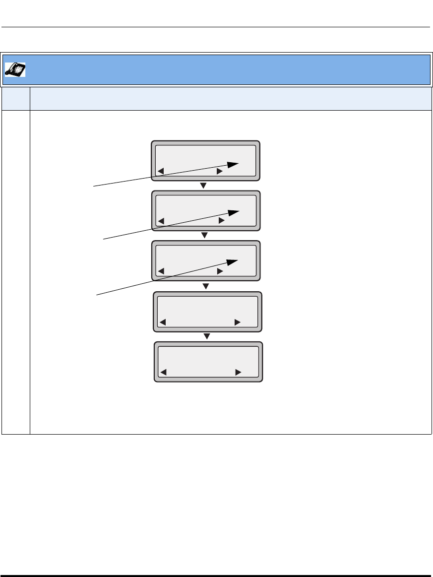
Operational Features
5-264 41-001160-03, Rev 00, Releaes 2.4
IP Phone Administrator Guide
2 Press the Call Forward key. The Call Forward Mode screen displays. Use the UP and DOWN arrow
keys to scroll through each state type.
In the above example, the account has CFWD All and CFWD NoAns enabled as indicated by a
checkmark ( 3). The CFWD Busy setting is enabled but no call forward phone number is configured
as indicated by a !
Aastra IP Phone UI
Step Action
Indicates
Indicates
CFWD ALL
CFWD NoAns
Indicates
no CFWD
phone number
configured for
Cfwd Mode
Done
1. All
Change
Cfwd Mode
Done
2. Busy
Change
Cfwd Mode
Done
3. NoAns
Change
Cfwd Mode
Done
4. All Off
Set
Cfwd Mode
Done
5. All On
Set
!
enabled
Busy
enabled
Draft 1
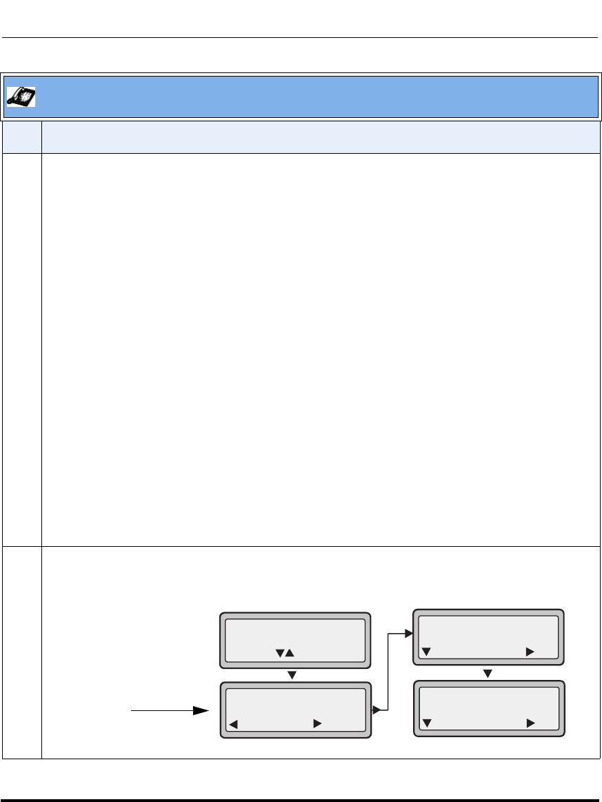
Operational Features
41-001160-03, Rev 00, Releaes 2.4 5-265
Configuring Operational Features
3 Select a state using the UP and DOWN arrow keys.
You can enable/disable a specific account on the phone with any or all of the following states.
However, the configuration you set will apply to all accounts on the phone.
•All - Enables CFWD All on the phone and forwards all incoming calls to the specified number.
•Busy - Enables CFWD Busy on the phone and forwards incoming calls to a specified number if
DND has been enabled OR if the phone is currently engaged in another call.
•No Answer - Enables CFWD NoAns on the phone and forwards incoming calls to a specified
number if the call has not been answered for the specified number of rings.
Note: If CFWD All AND CFWD Busy AND CFWD NoAns are all enabled (and/or if the account has
DND enabled), the CFWD All settings take precedence over CFWD Busy and CFWD NoAns.
You can also use the following keys if required:
All Off - Disables all CFWD states for the phone.
All On - Enables all CFWD states for the phone.
Note: In “Phone” mode, the initial configuration you set for an account applies to all the
accounts on the phone.
4 Press the CHANGE key for the mode you selected in step 2. Scroll to the CFWD State screen. This
displays the current state of the mode you selected. In the following example, the CFWD All state is
ON.
Aastra IP Phone UI
Step Action
CFWD State
Screen
1. Cfwd All
1. Cfwd State
Done
On
Change
Cfwd State
Next
On
Set
Cfwd State
Next
Off
Set
Use to view
Change
Draft 1
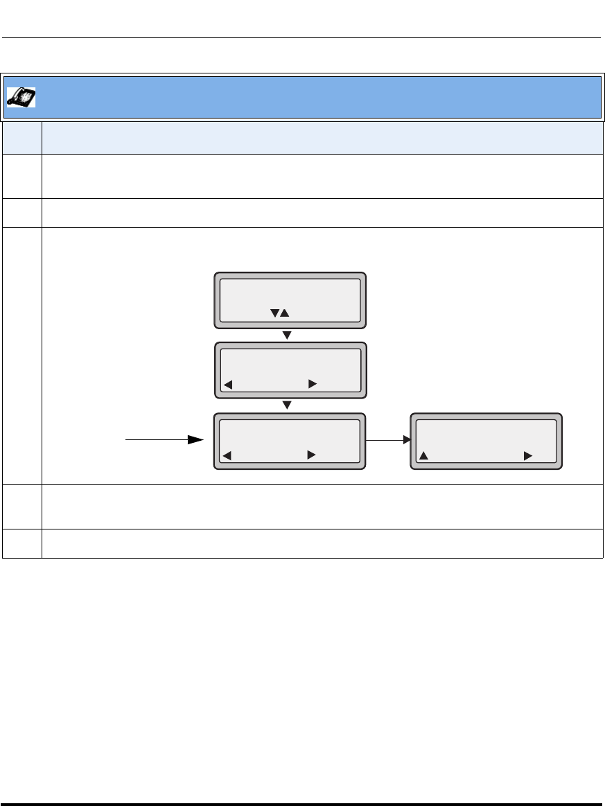
Operational Features
5-266 41-001160-03, Rev 00, Releaes 2.4
IP Phone Administrator Guide
5 Press the CHANGE key in the CFWD State screen. Press NEXT to toggle the state of the CFWD
state ON or OFF. In the example in Step 4, you press NEXT to change the option to OFF.
6 Press the SET key to save the change.
7 In the CFWD State screen, press the DOWN arrow key to scroll to the CFWD Number screen and
press CHANGE.
8 Enter a phone number to apply to the current state in focus. When the phone is in the state you
specified, and a call comes into the phone, it forwards the call to the number you specify.
9 Press SET to save the change.
Aastra IP Phone UI
Step Action
CFWD Number
Screen 2. Cfwd Number
Done Change
Cfwd Number
Cancel
__
Set
Change
1. Cfwd All
1. Cfwd State
Done
On
Change
Use to view
Draft 1

Operational Features
41-001160-03, Rev 00, Releaes 2.4 5-267
Configuring Operational Features
10 For the CFWD No Answer state, in the CFWD Number screen, press the DOWN arrow key to scroll
to the CFWD No. Rings screen and press CHANGE.
11 Press the NEXT key to select the number of rings to apply to the phone for call forwarding incoming
calls. Valid values are 1 to 20. Default is 1.
When the phone receives an incoming call, and call forward is configured on the phone, the phone
rings the number of times you specify in the No. Rings screen, and then forwards the call.
12 Press SET to save the change.
13 Press DONE to save CFWD All Number, CFWD All State, CFWD Busy Number, CFWD Busy State,
CFWD No Answer Number, CFWD No Answer State, CFWD No Answer Rings.
Each time you press DONE, the following “Apply Changes” screen displays.
Aastra IP Phone UI
Step Action
CFWD No.
Rings Screen 2. Cfwd Number
Done Change
1. Cfwd NoAns
1. Cfwd State
Done
On
Change
Use to view
3. No. Rings
Done Change
No. Rings
1
Change
Next Set
Apply Changes?
0 Cancel
# Confirm
Draft 1
Operational Features
5-268 41-001160-03, Rev 00, Releaes 2.4
IP Phone Administrator Guide
14 Press # to confirm the change(s) each time the “Apply Changes” screen displays.
All the same changes are saved to all accounts on the phone.
Aastra IP Phone UI
Step Action
Draft 1
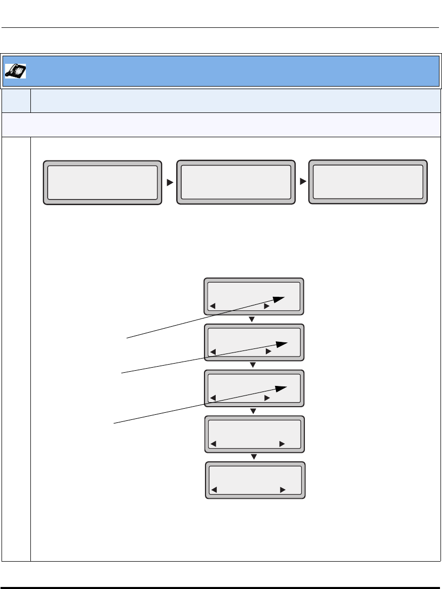
Operational Features
41-001160-03, Rev 00, Releaes 2.4 5-269
Configuring Operational Features
CFWD in Custom Mode (9143i, 6751i, and 6753i)
1Use the RIGHT and LEFT arrow keys to scroll through each account.
In the above example, Screenname1, Screenname2, and Screenname3, are three accounts
configured on the phone. All three accounts have CFWD enabled as indicated by the “CFWD All”,
“CFWD Busy”, and “CFWD NoAns” messages.
Press the Call Forward key. The CFWD Account screens display. Use the UP and DOWN arrow
keys to scroll through each account.
In the above example, Screenname1 has one or more CFWD states enabled as indicated by a
checkmark ( 3). Screenname2 has one or more CFWD states disabled as indicated by an X.
Screenname3 has one or more CFWD states configured but a specific state has no call forward
phone number configured as indicated by a !. Items 4 and 5 allow you to disable or enable CFWD on
all accounts, respectively.
Aastra IP Phone UI
Step Action
Screenname1
CFWD All
Jan 1 12:96
1Screenname2
Jan 1 12:96
2Screenname3
Jan 1 12:96
3
CFWD NoAns
CFWD Busy
Indicates
Indicates
CFWD Enabled
CFWD Disabled
Indicates
no CFWD phone
number
Call Forward
Done
1. Screenname1
Change
Call Forward
Done
2. Screenname2
Change
X
Call Forward
Done
3. Screenname3
Change
Call Forward
Done
4. All Off
Set
Call Forward
Done
5. All On
Set
!
configured
Draft 1

Operational Features
5-270 41-001160-03, Rev 00, Releaes 2.4
IP Phone Administrator Guide
2 Select an account to configure. Press the CHANGE key. The CFWD Mode screen displays. Use the
UP and DOWN arrow keys to scroll through each state screen.
In the above example, the account has CFWD All and CFWD NoAns enabled as indicated by a
checkmark ( 3). The CFWD Busy setting is enabled for the account but has no call forward phone
number configured as indicated by a !.
Aastra IP Phone UI
Step Action
Indicates
Indicates
CFWD All
CFWD NoAns
Indicates
no CFWD
phone number
configured for
Cfwd Mode
Done
1. All
Change
Cfwd Mode
Done
2. Busy
Change
Cfwd Mode
Done
3. NoAns
Change
Cfwd Mode
Done
4. All Off
Set
Cfwd Mode
Done
5. All On
Set
!
enabled
Busy
enabled
Draft 1

Operational Features
41-001160-03, Rev 00, Releaes 2.4 5-271
Configuring Operational Features
3 Select a state for the account(s) in focus using the UP and DOWN arrow keys.
You can enable/disable any or all of the following states for a specific account or for all accounts (with
individual configurations):
•All - Enables CFWD All for an account and forwards all incoming calls for that account, to the
specified number. The phone number can be different between accounts.
•Busy - Enables CFWD Busy for an account and forwards incoming calls to a specified number if
DND has been enabled for that account OR if that account is currently engaged in another call.
The phone number can be different between accounts.
•No Answer - Enables CFWD NoAns for an account and forwards incoming calls to a specified
number if the call has not been answered for a specified number of rings. The phone number can
be different between accounts.
Note: If CFWD All AND CFWD Busy AND CFWD NoAns are all enabled (and/or if the account has
DND enabled), the CFWD All settings take precedence over CFWD Busy and CFWD NoAns.
You can also use the following keys if required:
All Off - Disables all CFWD states for the current account in focus or all accounts.
All On - Enables all CFWD states for the current account in focus or all accounts.
4 Press the CHANGE key for the mode you selected in step 2. Scroll to the CFWD State screen. This
displays the current state of the mode you selected. In the following example, the CFWD All state is
ON.
Aastra IP Phone UI
Step Action
CFWD State
Screen
1. Cfwd All
1. Cfwd State
Done
On
Change
Cfwd State
Next
On
Set
Cfwd State
Next
Off
Set
Use to view
Change
Draft 1

Operational Features
5-272 41-001160-03, Rev 00, Releaes 2.4
IP Phone Administrator Guide
5 Press the CHANGE key in the CFWD State screen. Press NEXT to toggle the state of the CFWD
state ON or OFF. In the example in Step 4, you press NEXT to change the option to OFF.
6 Press the SET key to save the change.
7 In the CFWD State screen, press the DOWN arrow key to scroll to the CFWD Number screen and
press CHANGE.
8 Enter a phone number to apply to the current state in focus. When the phone is in the state you
specified, and a call comes into the phone, it forwards the call to the number you specify.
9 Press SET to save the change.
Aastra IP Phone UI
Step Action
CFWD Number
Screen 2. Cfwd Number
Done Change
Cfwd Number
Cancel
__
Set
Change
1. Cfwd All
1. Cfwd State
Done
On
Change
Use to view
Draft 1
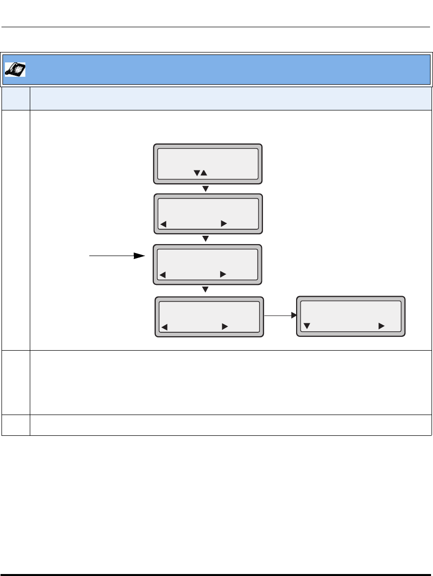
Operational Features
41-001160-03, Rev 00, Releaes 2.4 5-273
Configuring Operational Features
10 For the CFWD No Answer state, in the CFWD Number screen, press the DOWN arrow key to scroll
to the CFWD No. Rings screen and press CHANGE.
11 Press the NEXT key to select the number of rings to apply to the phone for call forwarding incoming
calls. Valid values are 1 to 20. Default is 1.
When the phone receives an incoming call, and call forward is configured on the phone, the phone
rings the number of times you specify in the No. Rings screen, and then forwards the call.
12 Press SET to save the change.
Aastra IP Phone UI
Step Action
CFWD No.
Rings Screen 2. Cfwd Number
Done Change
1. Cfwd NoAns
1. Cfwd State
Done
On
Change
Use to view
3. No. Rings
Done Change
No. Rings
1
Change
Next Set
Draft 1
Operational Features
5-274 41-001160-03, Rev 00, Releaes 2.4
IP Phone Administrator Guide
13 Press DONE to save CFWD All Number, CFWD All State, CFWD Busy Number, CFWD Busy State,
CFWD No Answer Number, CFWD No Answer State, CFWD No Answer Rings.
Each time you press DONE, the following “Apply Changes” screen displays.
14 Press # to confirm the change(s) each time the “Apply Changes” screen displays.
All changes are saved to the phone for all accounts.
Aastra IP Phone UI
Step Action
Apply Changes?
0 Cancel
# Confirm
Draft 1
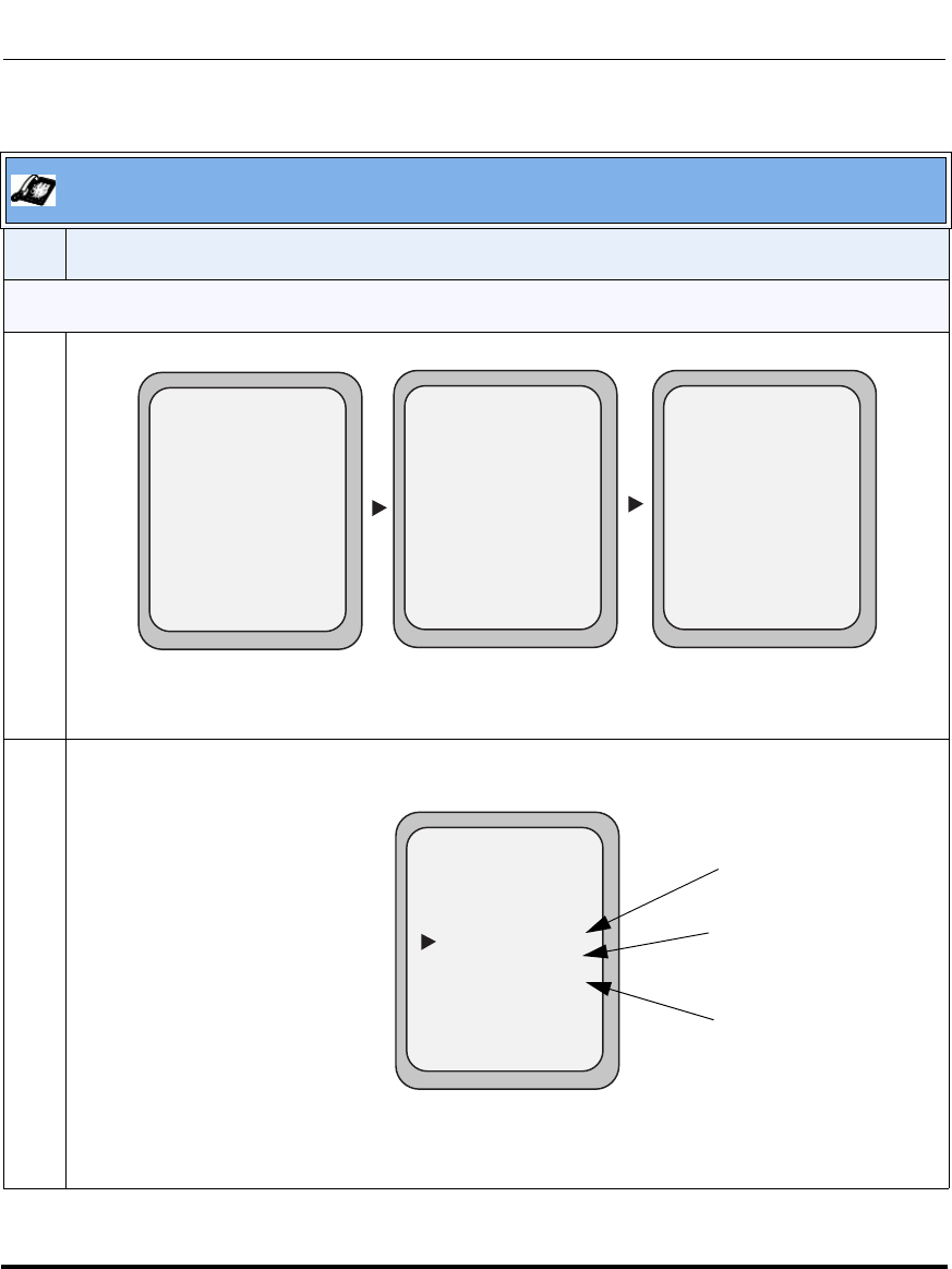
Operational Features
41-001160-03, Rev 00, Releaes 2.4 5-275
Configuring Operational Features
.
Aastra IP Phone UI
Step Action
CFWD in Account Mode (9480i, 9480i CT, 6755i, 6757i, and 6757i CT)
1Use the RIGHT and LEFT arrow keys to scroll through each account.
In the above example, Screenname1, Screenname2, and Screenname3, are three accounts
configured on the phone. Screenname1 has “CFWD All” enabled, Screenname2 has “CFWD Busy”
enabled, and Screenname3 has CFWD disabled as indicated by no message displayed.
2 Press the Call Forward key. The Call Forward Mode screen displays for the account you selected.
Use the UP and DOWN arrow keys to scroll through each state type.
In the above example, CFWD All is enabled as indicated by a checkmark ( 3), CFWD Busy is
enabled but no call forward phone number is configured as indicated by a !, and CFWD NoAns is
disabled as indicated by an X.
Tues Jan1 10:00am
Services
Dir
Callers
L1
- Call Fwd
Screenname1
CFWD All
Tues Jan1 10:00am
Services
Dir
Callers
L2
- Call Fwd
Screenname2
Tues Jan1 10:00am
Services
Dir
Callers
L3
- Call Fwd
Screenname3
CFWD Busy
Call Forward Mode
- Change
- All Off
- All On
Cancel -
Done -
CopytoAll -
1. All
2. Busy
3. No Answer
Services
Dir
Callers
!
X
Indicates
Indicates
CFWD Enabled
CFWD Disabled
Indicates
no CFWD phone
number configured
Call Forward
Mode Screen
Draft 1

Operational Features
5-276 41-001160-03, Rev 00, Releaes 2.4
IP Phone Administrator Guide
3 Select a state for the account(s) in focus using the UP and DOWN arrow keys.
You can enable/disable any or all of the following states for an account:
•All - Enables CFWD All for an account and forwards all incoming calls for that account, to the
specified number.
•Busy - Enables CFWD Busy for an account and forwards incoming calls to a specified number if
DND has been enabled for that account OR if the account is currently engaged in another call.
•No Answer - Enables CFWD NoAns for an account and forwards incoming calls to a specified
number if the call has not been answered for the specified number of rings.
Note: If CFWD All AND CFWD Busy AND CFWD NoAns are all enabled (and/or if the account has
DND enabled), the CFWD All settings take precedence over CFWD Busy and CFWD NoAns.
You can also use the following keys if required:
All Off Key- Disables all CFWD states for the current account in focus.
All On Key - Enables all CFWD states for the current account in focus.
CopytoAll Key - Copies the call forward phone number and state of the Call Forward mode (All,
Busy, No Answer) in focus to every Call Forward mode of that account. For example, if you have the
cursor pointing at the “All” state and it is enabled and has a call forward phone number configured,
pressing the CopytoAll Key enables the Busy state and the NoAns state and assigns the same
phone number to both states.
Cancel Key - Cancels any configuration you may have made without saving. To cancel a
configuration, you must press this CANCEL key before pressing the DONE key.
Aastra IP Phone UI
Step Action
Draft 1
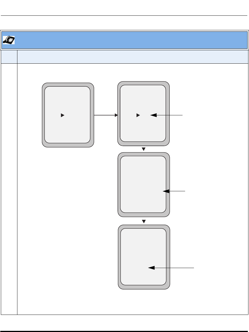
Operational Features
41-001160-03, Rev 00, Releaes 2.4 5-277
Configuring Operational Features
4 For the CFWD No Answer state, press the CHANGE key for the mode you selected in step 2. This
displays the Call Forward State screen. In the following example, the CFWD All state is ON.
Note: You can press the AllAccts key to copy the settings in the current Call Forward Settings
screen for a specific call forward mode, to every account on the phone. Every account will have the
same settings for that call forward mode.
Aastra IP Phone UI
Step Action
Call Forward
Mode NoAns
- AllAccts
Cancel -
Done -
State: On
Number: 5551212
No. Rings: 1
Services
Dir
Callers
- Change
Call Forward
Mode NoAns
- AllAccts
Cancel -
Done -
State: Off
Number: 5551212
No. Rings: 1
Services
Dir
Callers
- Change
Change
Call Forward
Mode NoAns
- AllAccts
Cancel -
Done -
State: Off
Number: 5551212__
No. Rings: 1
Services
Dir
Callers
- Backspace
Call Forward
Mode NoAns
- AllAccts
Cancel -
Done -
State: Off
Number: 5551212
No. Rings: 3
Services
Dir
Callers
- Change
Change the
State
Change the
Number
Change the
No. Rings
Call Forward
State Screen
Draft 1

Operational Features
5-278 41-001160-03, Rev 00, Releaes 2.4
IP Phone Administrator Guide
5 Press the CHANGE key in the CFWD State screen. With the cursor in the “State” field, toggle the
state ON and OFF by pressing the CHANGE key.
Note: You can press the AllAccts key to copy the settings in the current Call Forward Settings
screen for a specific call forward mode, to every account on the phone. Every account will have the
same settings for that call forward mode.
6Use the DOWN arrow key to scroll to the “Number” field. Enter a phone number to apply to the
current state in focus. When the phone is in the state you specified, and a call comes into the phone,
it forwards the call to the number you specify.
Use the BACKSPACE key if required to delete characters.
Note: You can press the AllAccts key to copy the settings in the current Call Forward Settings
screen for a specific call forward mode, to every account on the phone. Every account will have the
same settings for that call forward mode.
7Use the DOWN arrow key to scroll to the “No. Rings” field. Press the CHANGE key to select the
number of rings to apply to the phone for call forwarding incoming calls. Valid values are 1 to 20.
Default is 1.
When the phone receives an incoming call, and call forward is configured on the phone, the phone
rings the number of times you specify in the No. Rings screen, and then forwards the call.
Note: You can press the AllAccts key to copy the settings in the current Call Forward Settings
screen for a specific call forward mode, to every account on the phone. Every account will have the
same settings for that call forward mode.
8 Press DONE in the CFWD State Screen to save all changes.
Press DONE in the CFWD Mode Screen to save all changes.
Aastra IP Phone UI
Step Action
Draft 1
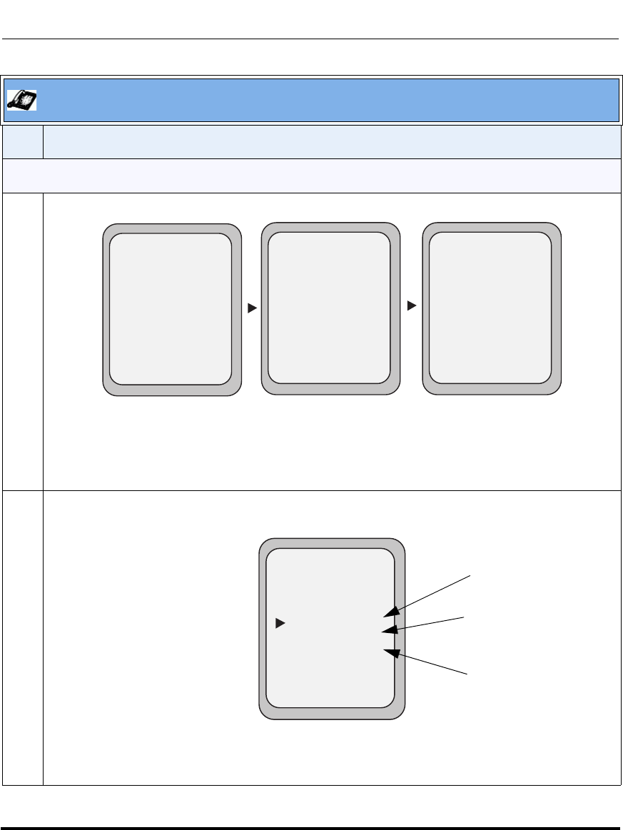
Operational Features
41-001160-03, Rev 00, Releaes 2.4 5-279
Configuring Operational Features
CFWD in Phone Mode (9480i, 9480i CT, 6755i, 6757i, and 6757i CT)
1Use the RIGHT and LEFT arrow keys to scroll through each account.
In the above example, Screenname1, Screenname2, and Screenname3, are three accounts
configured on the phone. Screenname1, 2 and 3 have “CFWD All” enabled.
Note: In “Phone” mode, the initial configuration you set for an account applies to all the
accounts on the phone.
2 Press the Call Forward key. The Call Forward Mode screen displays. Use the UP and DOWN arrow
keys to scroll through each state type.
In the above example, CFWD All is enabled as indicated by a checkmark ( 3), CFWD Busy is
enabled but no call forward phone number is configured as indicated by a !, and CFWD No Answer
is disabled, as indicated by an X.
Aastra IP Phone UI
Step Action
Tues Jan1 10:00am
Services
Dir
Callers
L1
- Call Fwd
Screenname1
CFWD All
Tues Jan1 10:00am
Services
Dir
Callers
L2
- Call Fwd
Screenname2
Tues Jan1 10:00am
Services
Dir
Callers
L3
- Call Fwd
Screenname3
CFWD All CFWD All
Call Forward Mode
- Change
- All Off
- All On
Cancel -
Done -
CopytoAll -
1. All
2. Busy
3. No Answer
Services
Dir
Callers
!
X
Indicates
Indicates
CFWD Enabled
CFWD Disabled
Indicates
no CFWD phone
number configured
Call Forward
Mode Screen
Draft 1

Operational Features
5-280 41-001160-03, Rev 00, Releaes 2.4
IP Phone Administrator Guide
3 Select a state for the phone using the UP and DOWN arrow keys.
You can enable/disable a specific account on the phone with any or all of the following states.
However, the configuration you set will apply to all accounts on the phone.
•All - Enables CFWD All on the phone and forwards all incoming calls to the specified number.
•Busy - Enables CFWD Busy on the phone and forwards incoming calls to a specified number if
DND has been enabled OR if the phone is currently engaged in another call.
•No Answer - Enables CFWD NoAns on the phone and forwards incoming calls to a specified
number if the call has not been answered for the specified number of rings.
Note: If CFWD All AND CFWD Busy AND CFWD NoAns are all enabled (and/or if the account has
DND enabled), the CFWD All settings take precedence over CFWD Busy and CFWD NoAns.
You can also use the following keys if required:
All Off Key- Disables all CFWD modes.
All On Key - Disables all CFWD modes.
CopytoAll Key - Copies the call forward phone number and state of the Call Forward mode (All,
Busy, No Answer) in focus to every Call Forward mode. For example, if you have the cursor pointing
at the “All” state and it is enabled and has a call forward phone number configured, pressing the
CopytoAll Key enables the Busy state and the NoAns state and assigns the same phone number to
both states.
Cancel Key - Cancels any configuration you may have made without saving. To cancel a
configuration, you must press this CANCEL key before pressing the DONE key.
Aastra IP Phone UI
Step Action
Draft 1

Operational Features
41-001160-03, Rev 00, Releaes 2.4 5-281
Configuring Operational Features
4 In the CFWD No Answer state, press the CHANGE key for the mode you selected in step 2. This
displays the Call Forward State screen. In the following example, the CFWD All state is ON.
5 Press the CHANGE key in the CFWD State screen. With the cursor in the “State” field, toggle the
state ON and OFF by pressing the CHANGE key.
Aastra IP Phone UI
Step Action
Call Forward
Mode NoAns
Cancel -
Done -
State: On
Number: 5551212
No. Rings: 1
Services
Dir
Callers
- Change
Call Forward
Mode NoAns
Cancel -
Done -
State: Off
Number: 5551212
No. Rings: 1
Services
Dir
Callers
- Change
Change
Call Forward
Mode NoAns
Cancel -
Done -
State: Off
Number: 5551212__
No. Rings: 1
Services
Dir
Callers
- Backspace
Call Forward
Mode NoAns
Cancel -
Done -
State: Off
Number: 5551212
No. Rings: 3
Services
Dir
Callers
- Change
Change the
State
Change the
Number
Change the
No. Rings
Call Forward
State Screen
Draft 1
Operational Features
5-282 41-001160-03, Rev 00, Releaes 2.4
IP Phone Administrator Guide
6Use the DOWN arrow key to scroll to the “Number” field. Enter a phone number to apply to the
current state in focus. When the phone is in the state you specified, and a call comes into the phone,
it forwards the call to the number you specify.
Use the BACKSPACE key if required to delete characters.
7Use the DOWN arrow key to scroll to the “No. Rings” field. Press the CHANGE key to select the
number of rings to apply to the phone for call forwarding incoming calls. Valid values are 1 to 20.
Default is 1.
When the phone receives an incoming call, and call forward is configured on the phone, the phone
rings the number of times you specify in the No. Rings screen, and then forwards the call.
8 Press DONE in the CFWD State Screen to save all changes.
Press DONE in the CFWD Mode Screen to save all changes.
Note: In “Phone” mode, the configuration applies to all the accounts on the phone.
Aastra IP Phone UI
Step Action
Draft 1

Operational Features
41-001160-03, Rev 00, Releaes 2.4 5-283
Configuring Operational Features
CFWD in Custom Mode (9480i, 9480i CT, 6755i, 6757i, and 6757i CT)
1Use the RIGHT and LEFT arrow keys to scroll through each account.
In the above example, Screenname1, Screenname2, and Screenname3, are three accounts
configured on the phone. Screenname1 has “CFWD All” enabled, Screenname2 has “CFWD Busy”
enabled, and Screenname3 has CFWD disabled as indicated by no message displayed.
2 With the account in focus on the IP Phone UI, press the Call Forward key. The Call Forward Account
screen displays which lists all the accounts on the phone. Use the UP and DOWN arrow keys to
scroll through each account.
In the above example, Screenname1 has one or more CFWD states enabled as indicated by a
checkmark ( 3), Screenname 2 has one or more CFWD states enabled but a specific state has no
call forward phone number configured as indicated by a !, and Screenname3 has one or more
CFWD states disabled as indicated by an X.
Aastra IP Phone UI
Step Action
Tues Jan1 10:00am
Services
Dir
Callers
L1
- Call Fwd
Screenname1
CFWD All
Tues Jan1 10:00am
Services
Dir
Callers
L2
- Call Fwd
Screenname2
Tues Jan1 10:00am
Services
Dir
Callers
L3
- Call Fwd
Screenname3
CFWD Busy
Indicates
Indicates
CFWD Enabled
CFWD Disabled
Indicates
no CFWD phone
number configured
Call Forward
Account Screen
Call Forward
- Change
- All Off
- All On
Cancel -
Done -
X
CopytoAll -
1. Screenname1
2. Screenname2
3. Screenname3
!
Services
Dir
Callers
Draft 1
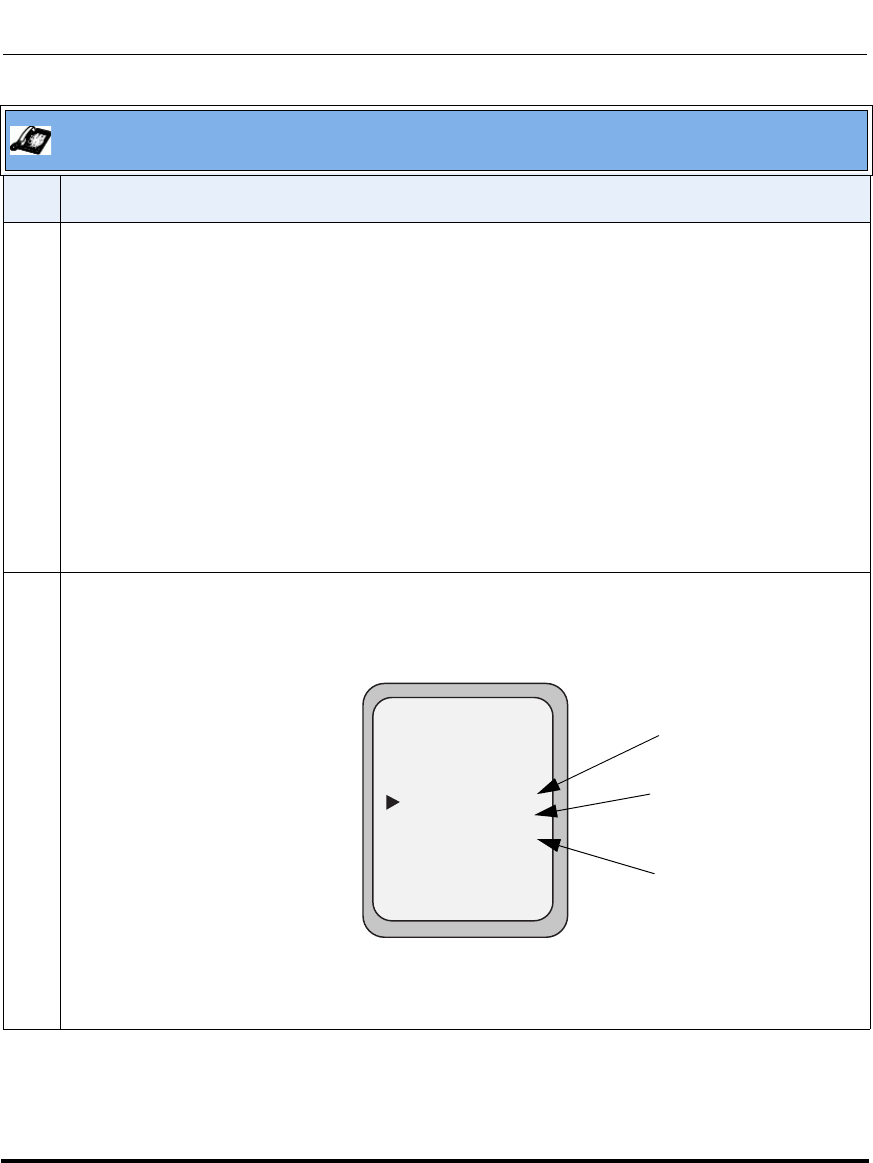
Operational Features
5-284 41-001160-03, Rev 00, Releaes 2.4
IP Phone Administrator Guide
3 Select an account using the UP and DOWN arrow keys.
You can also use the following keys if required:
All Off Key- Disables CFWD for all accounts on the phone.
All On Key - Enables CFWD for all accounts on the phone.
CopytoAll Key - Copies all settings for the account you select, to all other accounts on the Call
Forward Account screen. For example, if you have the cursor pointing at Screenname1, and you
press the CopytoAll key, all of the CFWD settings for Screenname1 are copied to Screenname2 and
Screenname3.
Cancel Key - Cancels any configuration you may have made without saving. To cancel a
configuration, you must press this CANCEL key before pressing the DONE key.
4 After selecting an account, press CHANGE.
The Call Forward Mode screen displays for the account you selected. Use the UP and DOWN arrow
keys to scroll through each state type.
In the above example, CFWD All is enabled as indicated by a checkmark ( 3), CFWD Busy is
enabled but no call forward phone number is configured as indicated by a !, and CFWD No Answer
is disabled, as indicated by an X.
Aastra IP Phone UI
Step Action
Call Forward Mode
- Change
- All Off
- All On
Cancel -
Done -
CopytoAll -
1. All
2. Busy
3. No Answer
Services
Dir
Callers
!
X
Indicates
Indicates
CFWD Enabled
CFWD Disabled
Indicates
no CFWD phone
number configured
Call Forward
Mode Screen
Draft 1

Operational Features
41-001160-03, Rev 00, Releaes 2.4 5-285
Configuring Operational Features
5 Select a state for the selected account(s) using the UP and DOWN arrow keys.
You can enable/disable any or all of the following states for a specific account or for all accounts (with
individual configurations):
•All - Enables CFWD All for an account and forwards all incoming calls for that account, to the
specified number. The phone number can be different between accounts.
•Busy - Enables CFWD Busy for an account and forwards incoming calls to a specified number if
DND has been enabled for that account OR if that account is currently engaged in another call.
The phone number can be different between accounts.
•No Answer - Enables CFWD NoAns for an account and forwards incoming calls to a specified
number if the call has not been answered for a specified number of rings. The phone number can
be different between accounts.
Note: If CFWD All AND CFWD Busy AND CFWD NoAns are all enabled (and/or if the account has
DND enabled), the CFWD All settings take precedence over CFWD Busy and CFWD NoAns.
You can also use the following keys if required:
All Off Key- Disables all CFWD states for the selected account.
All On Key - Enables all CFWD states for the selected account.
CopytoAll Key - Copies the call forward phone number and state of the selected Call Forward mode
(All, Busy, No Answer) to every Call Forward mode of that account. For example, if you have the
cursor pointing at the “All” state and it is enabled and has a call forward phone number configured,
pressing the CopytoAll Key enables the Busy state and the NoAns state and assigns the same
phone number to both states.
Cancel Key - Cancels any configuration you may have made without saving. To cancel a
configuration, you must press this CANCEL key before pressing the DONE key.
Aastra IP Phone UI
Step Action
Draft 1
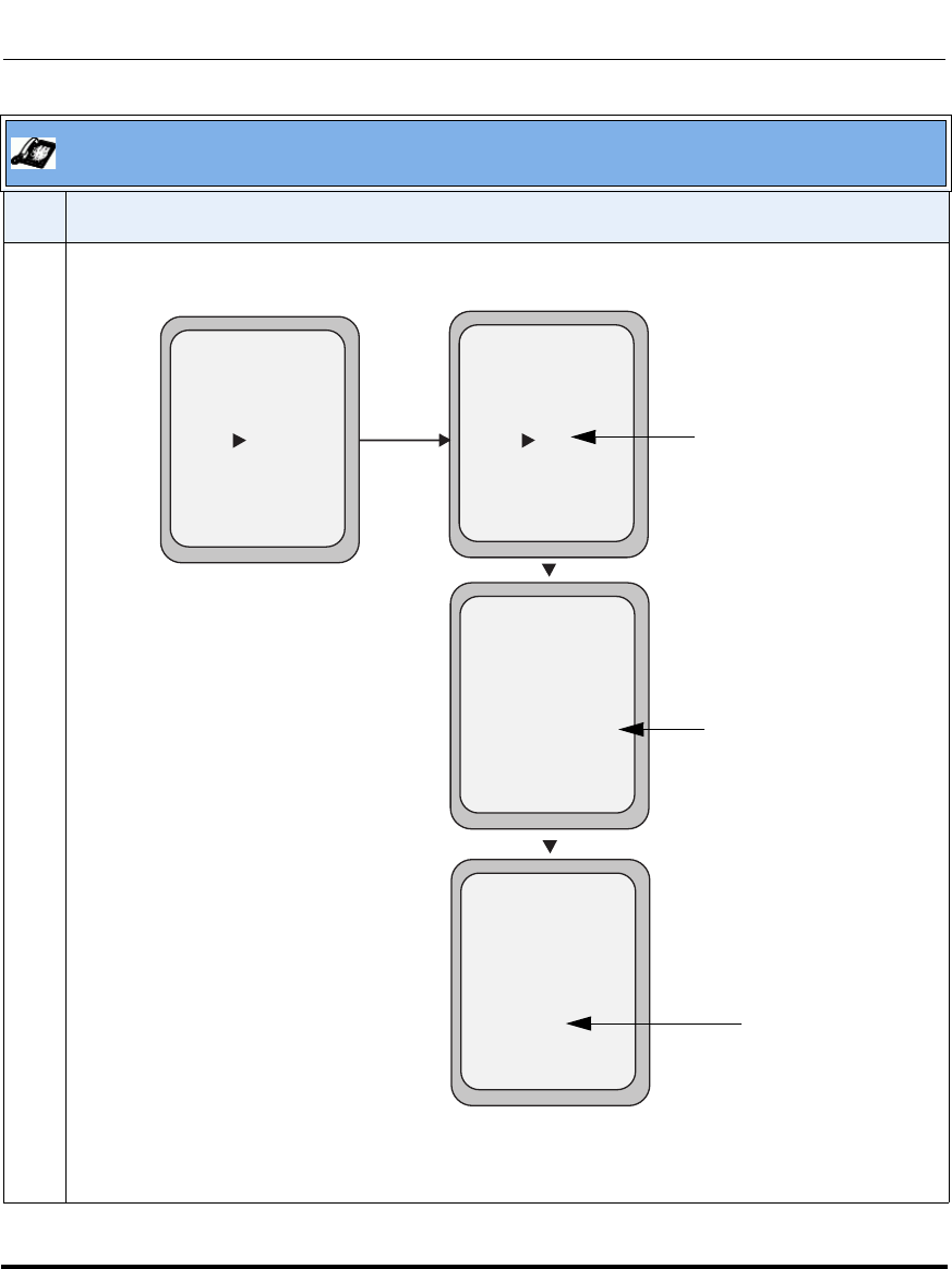
Operational Features
5-286 41-001160-03, Rev 00, Releaes 2.4
IP Phone Administrator Guide
6 Press the CHANGE key for the mode you selected in step 4. This displays the Call Forward State
screen. In the following example, the CFWD All state is ON.
Note: You can press the AllAccts key to copy the settings in the current Call Forward Settings
screen for a specific call forward mode, to every account on the phone. Every account will have the
same settings for that call forward mode.
Aastra IP Phone UI
Step Action
Call Forward
Mode NoAns
- AllAccts
Cancel -
Done -
State: On
Number: 5551212
No. Rings: 1
Services
Dir
Callers
- Change
Call Forward
Mode NoAns
- AllAccts
Cancel -
Done -
State: Off
Number: 5551212
No. Rings: 1
Services
Dir
Callers
- Change
Change
Call Forward
Mode NoAns
- AllAccts
Cancel -
Done -
State: Off
Number: 5551212__
No. Rings: 1
Services
Dir
Callers
- Backspace
Call Forward
Mode NoAns
- AllAccts
Cancel -
Done -
State: Off
Number: 5551212
No. Rings: 3
Services
Dir
Callers
- Change
Change the
State
Change the
Number
Change the
No. Rings
Call Forward
State Screen
Draft 1

Operational Features
41-001160-03, Rev 00, Releaes 2.4 5-287
Configuring Operational Features
7 Press the CHANGE key in the CFWD State screen. With the cursor in the “State” field, toggle the
state ON and OFF by pressing the CHANGE key.
Note: You can press the AllAccts key to copy the settings in the current Call Forward Settings
screen for a specific call forward mode, to every account on the phone. Every account will have the
same settings for that call forward mode.
8Use the DOWN arrow key to scroll to the “Number” field. Enter a phone number to apply to the
current state in focus. When the phone is in the state you specified, and a call comes into the phone,
it forwards the call to the number you specify.
Use the BACKSPACE key if required to delete characters.
Note: You can press the AllAccts key to copy the settings in the current Call Forward Settings
screen for a specific call forward mode, to every account on the phone. Every account will have the
same settings for that call forward mode.
9Use the DOWN arrow key to scroll to the “No. Rings” field. Press the CHANGE key to select the
number of rings to apply to the phone for call forwarding incoming calls. Valid values are 1 to 20.
Default is 1.
When the phone receives an incoming call, and call forward is configured on the phone, the phone
rings the number of times you specify in the No. Rings screen, and then forwards the call.
Note: You can press the AllAccts key to copy the settings in the current Call Forward Settings
screen for a specific call forward mode, to every account on the phone. Every account will have the
same settings for that call forward mode.
10 Press DONE in the CFWD State screen to save all changes.
Press DONE in the CFWD Mode screen to save all changes.
Press DONE in the CFWD Account screen to save all changes.
Aastra IP Phone UI
Step Action
Draft 1
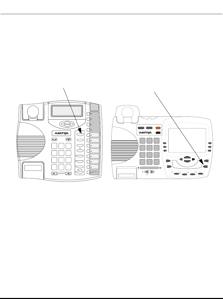
Operational Features
5-288 41-001160-03, Rev 00, Releaes 2.4
IP Phone Administrator Guide
Callers List
The IP phones have a "Callers List" feature that store the name, phone number,
and incremental calls, for each call received by the phone.
The following illustrations show the default location of the Callers List Key on
each type of phone model.
9480i/9480i CT
Callers List Key
9143i
Xfer
Conf
L2
L3
L1
Options
Save
Delete
Directory
Mute
ABC DEF
GHI JKL MNO
PQRS
TUV
WXYZ
1
4
3
6
2
5
798
0
*#
9480i
Conf Services
Xfer Icom
ABC DEF
GHI JKL MNO
PQRS
TUV
WXYZ
1
4
3
6
2
5
798
0
*#
Goodbye
Options
Hold Redial
L1 L2 L3 L4
Callers List Key under
Services Menu
Draft 1
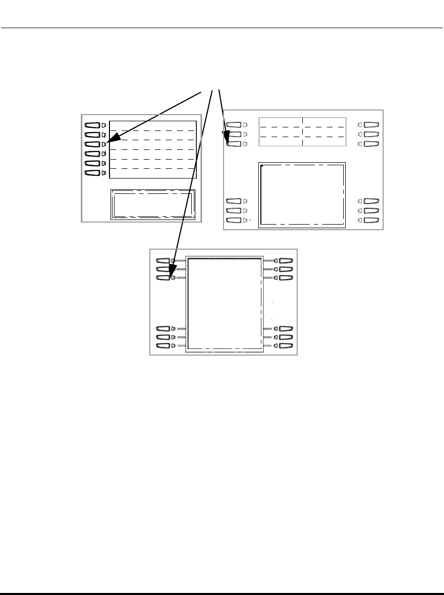
Operational Features
41-001160-03, Rev 00, Releaes 2.4 5-289
Configuring Operational Features
You can enable and disable the Callers List feature using the configuration files.
When disabled, the Callers List does not display on the IP phone UI and the Caller
List key is ignored when pressed.
When enabled, you can view, scroll, and delete line items in the Callers List from
the IP phone UI. You can also directly dial from a displayed line item in the
Callers List. You can download the Callers List to your PC for viewing using the
Aastra Web UI.
When you download the Callers List, the phone stores the callerlist.csv file to
your computer in comma-separated value (CSV) format.
6753i 6755i
6757i/6757i CT
Callers List Key
Draft 1
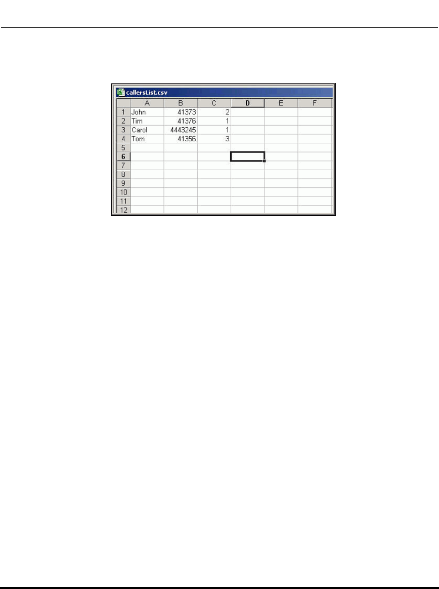
Operational Features
5-290 41-001160-03, Rev 00, Releaes 2.4
IP Phone Administrator Guide
You can use any spreadsheet application to open the file for viewing. The
following is an example of a Callers List in a spreadsheet application.
The file displays the name, phone number, and the line that the call came in on.
Draft 1
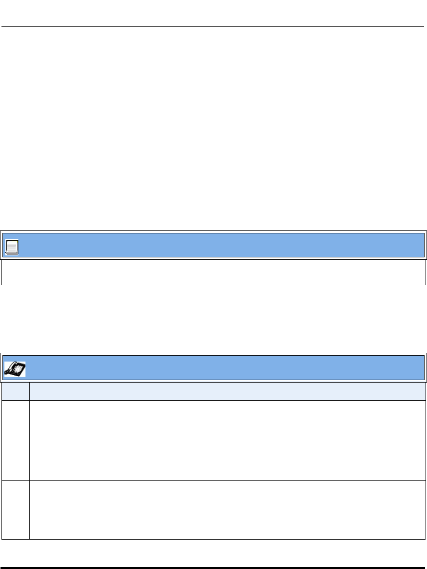
Operational Features
41-001160-03, Rev 00, Releaes 2.4 5-291
Configuring Operational Features
Enabling/Disabling Callers List
You can enable and disable user access to the Callers List on the IP phones using
the following parameter in the configuration files:
• callers list disabled
Valid values for this parameter are 0 (enabled) and 1 (disabled). If this parameter
is set to 0, the Callers List can be accessed by all users. If this parameter is
set to 1, the IP phone does not save any caller information to the Caller List. For
6757i and 6757i CT phones, the "Caller List" option on the IP phone is removed
from the Services menu, and the Caller List key is ignored if pressed by the user.
Use the following procedures to enable/disable the Callers List on the IP phones.
Using the Callers List
Use the following procedure to access and use the Callers List.
Configuration Files
For specific parameters you can set in the configuration files for enabling/disabling the Callers List, see
Appendix A, the section, “Callers List Settings” on page A-124.
IP Phone UI
Step Action
1On 9143i, 6753i, 6755i, 6757i, and 6757i CT:
Press the “Callers List” key on the phone to enter the Callers List.
On the 9480i, 9480i CT:
Press the “Services” key on the phone, and then select “Callers List” from the list of options.
2Use the r and s to scroll through the line items in the Callers List.
To the left of a line item, a b icon displays with the handset ON or OFF the receiver. The ON
receiver indicates the call came in as a missed call. The OFF receiver indicates the call came in and
was answered.
Draft 1
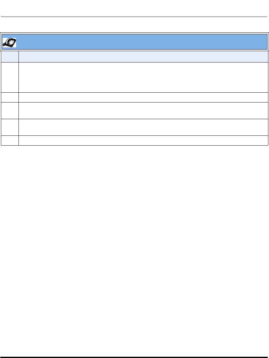
Operational Features
5-292 41-001160-03, Rev 00, Releaes 2.4
IP Phone Administrator Guide
3 To delete all entries in the Callers list, press the 3 Delete key at the "Callers List" header.
To delete a line item from the Callers List, select the line item you want to delete and press the 3
Delete key.
4 To cancel a delete function, press the r or the s Scroll keys.
5 To save a line item to a programmable key for speeddialing, press the 3 Save key and enter the line
number at the "Save to?" prompt that is already configured for speeddialing at a programmable key.
6 To dial a displayed entry from the Callers List, pick up the handset, press the d/f handsfree key, or
press a line key.
7 To exit the Callers List, press the “Callers List” key again or the “Goodbye” key.
IP Phone UI
Step Action
Draft 1
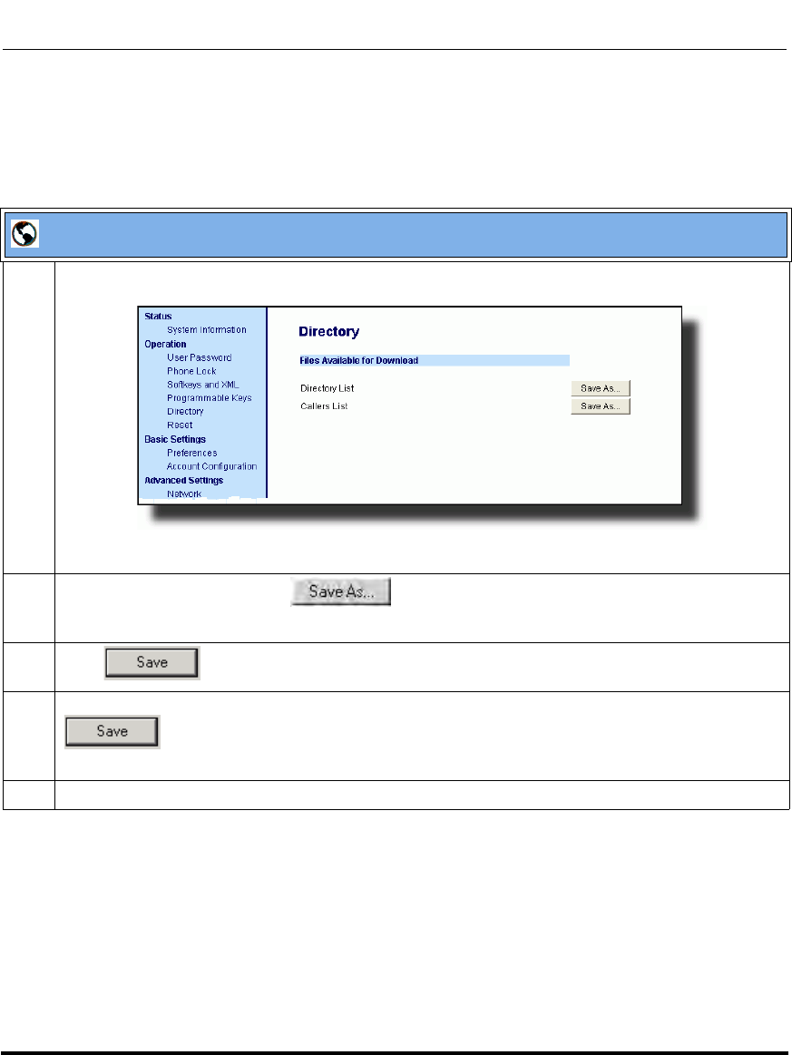
Operational Features
41-001160-03, Rev 00, Releaes 2.4 5-293
Configuring Operational Features
Downloading the Callers List
Use the following procedure to download the Callers List using the Aastra Web
UI.
Aastra Web UI
1 Click on Operation->Directory.
2 In the Callers List field, click on .
A “File Download” message displays.
3 Click .
4 Enter the location on your computer where you want to download the Callers List and click
.
The callerslist.csv file downloads to your computer.
5 Use a spreadsheet application to open and view the Callers List.
Draft 1

Operational Features
5-294 41-001160-03, Rev 00, Releaes 2.4
IP Phone Administrator Guide
Customizable Callers List and Services Keys
The IP phones currently have a Callers List key (all 5i Series phones) and a
Services key (9480i, 9480i CT, 6755i, 6757i, and 6757i CT). An Administrator
can specify URI overrides for these keys using the following parameters in the
configuration files:
• services script
• callers list script
Specifying URIs for these parameters cause the creation of an XML custom
application instead of the standard function of the Callers List and Services keys.
An Administrator can configure these parameters using the configuration files
only.
Creating Customizable Callers List and Services Keys
Use the following procedure to create customized Callers List and Services keys
on the IP Phone using the configuration files.
Configuration Files
For specific parameters you can set in the configuration files, see Appendix A, the section, “Customize
Callers List and Services Key” on page A-125.
Draft 1
Operational Features
41-001160-03, Rev 00, Releaes 2.4 5-295
Configuring Operational Features
Missed Calls Indicator
The IP phone has a "missed calls" indicator that increments the number of missed
calls to the phone. This feature is accessible from the IP phone UI only.
You can enable and disable the Missed Calls Indicator feature using the
configuration files. When disabled, the Missed Calls Indicator does not increment
as calls come into the IP phone.
When enabled, the number of calls that have not been answered increment on the
phone’s idle screen as "<number> New Calls". As the number of unanswered
calls increment, the phone numbers associated with the calls are stored in the
Callers List. The user can access the Callers List and clear the call from the list.
Once the user accesses the Callers List, the "<number> New Calls" on the idle
screen is cleared.
Enabling/Disabling Missed Calls Indicator
You can enable (turn on) and disable (turn off) the Missed Calls Indicator on the
IP phones using the following parameter in the configuration files:
• missed calls indicator disabled
Valid values for this parameter are 0 (enabled) and 1 (disabled). If this parameter
is set to 0, the indicator increments as unanswered calls come into the IP phone. If
set to 1, the indicator does not increment the unanswered calls.
Use the following procedures to enable/disable the Missed Calls Indicator on the
IP phones.
Note: The phones also include a “Missed-Calls-Message” field in a
“message summary” event of a SIP NOTIFY message.
Configuration Files
For specific parameters you can set in the configuration files for enabling/disabling the Missed Calls
Indicator, see Appendix A, the section, “Missed Calls Indicator Settings” on page A-131.
Draft 1
Operational Features
5-296 41-001160-03, Rev 00, Releaes 2.4
IP Phone Administrator Guide
Accessing and Clearing Missed Calls
Use the following procedure to access and clear missed calls from the Callers List.
Once you display the Callers List, the "<number> New Calls" indicator clears.
IP Phone UI
Step Action
1 Press the “Callers List” key on the phone to enter the Callers List.
2Use the r and s to scroll through the line items in the Callers List to find the line items that have
the b icon with the receiver ON. These are the missed calls to the phone.
3 To clear the line item from the Callers List, select the line item you want to clear and press the 3,
Clear, or Delete key (depending on your phone model).
Note: To cancel a delete function, press the r or the s Scroll keys.
The line item deletes from the Callers List.
Draft 1
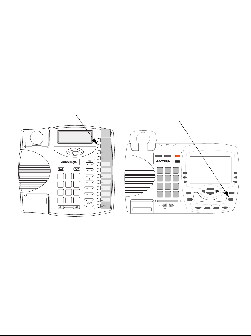
Operational Features
41-001160-03, Rev 00, Releaes 2.4 5-297
Configuring Operational Features
Directory List
The IP phones have a "Directory List" feature that allows you to store frequently
used names and numbers on the phone. You can also dial directly from the
directory entry.
The following illustrations show the default location of the Directory Key on each
type of phone model.
9480i/9480i CT
Directory Key
9143i
Xfer
Conf
L2
L3
L1
Options
Save
Delete
Directory
Mute
ABC DEF
GHI JKL MNO
PQRS
TUV
WXYZ
1
4
3
6
2
5
798
0
*#
9480i
Conf Services
Xfer Icom
ABC DEF
GHI JKL MNO
PQRS
TUV
WXYZ
1
4
3
6
2
5
798
0
*#
Goodbye
Options
Hold Redial
L1 L2 L3 L4
Directory Key under
Services Menu
Draft 1
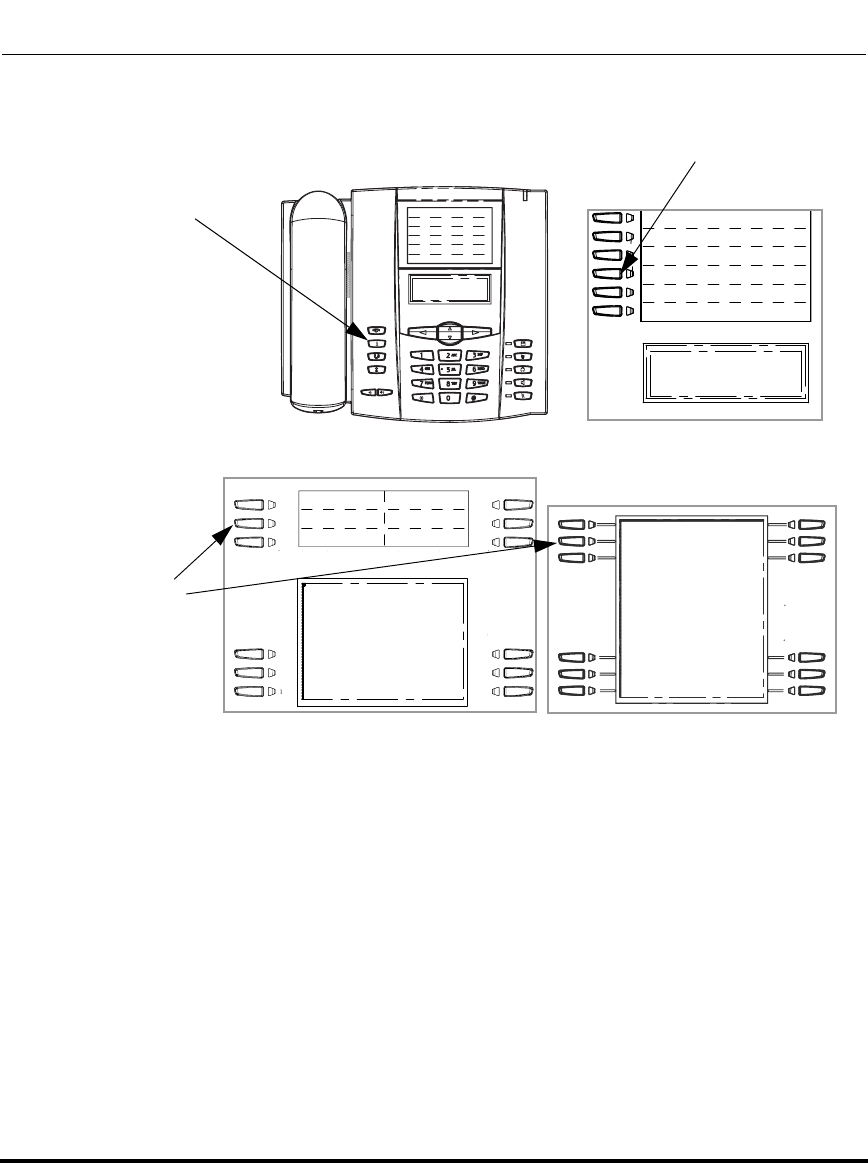
Operational Features
5-298 41-001160-03, Rev 00, Releaes 2.4
IP Phone Administrator Guide
6753i
6755i 6757i/6757i CT
Directory Key
Options Key
6751i
(Directory is
an option under
Services Menu)
Directory Key
Draft 1

Operational Features
41-001160-03, Rev 00, Releaes 2.4 5-299
Configuring Operational Features
Directory List Capabilities
In the Directory List a user or administrator can store a maximum of 7 numbers
associated with a unique name. You can apply pre-defined labels to the entry
which include, Office, Home, Cell, and Pager, or create your own labels. Labels
can be up to 14 characters in length.
You can also sort multiple numbers according to preference and perform a
quick-search feature that allows you to enter the first letter that corresponds to a
name in the Directory to find specific line items. The phone displays the first
name with this letter.The quick-search feature in the Directory List works only
when the Directory is first accessed.
Reference
For more detailed information about the Directory Key on your IP phone, and the
Directory List, see your model-specific User Guide.
Administrator/User Functions for Directory List
You can perform the following pertaining to the Directory List:
• You can enable and disable access to the Directory List using the
configuration files. When disabled, the Directory List does not display on the
IP phone UI and the Directory List softkey is ignored when pressed. This is an
administrator function only.
• If the Directory List is enabled, you can view, add, change, and delete entries
to/from the Directory List using the IP phone UI. You can also directly dial a
number from the Directory List. This is an administrator and user function.
• A public and private softkey can be used when at a line item in the Directory
List. The Private key toggles a number in the Directory List to private. The
Public key allows a number in the Directory List to be sent to the handsets. A
6757i CT accepts a maximum of 50 entries with the public attribute. This is an
administrator and user function.
• You can download the Directory List to your PC via the Aastra Web UI. The
phone stores the directorylist.csv file to your PC in comma-separated value
(CSV) format. This is an administrator and user function.
Draft 1
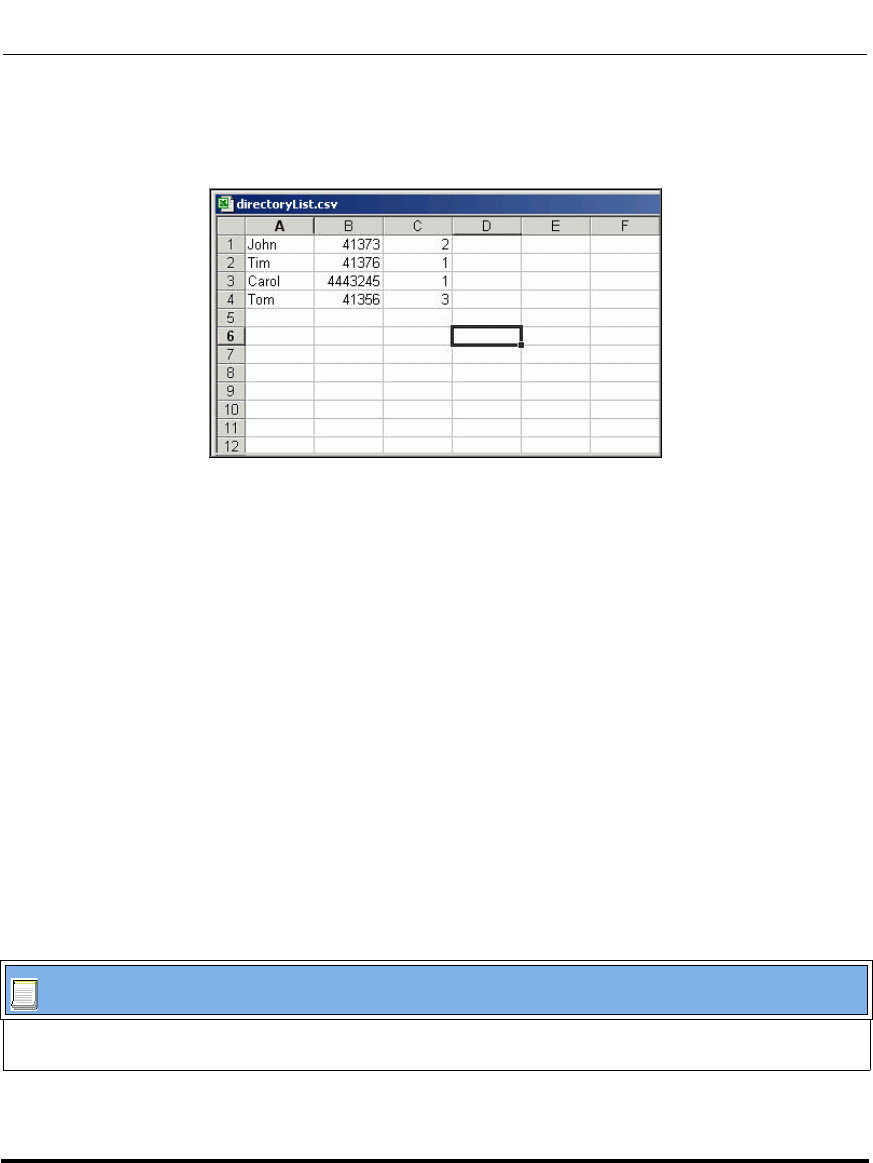
Operational Features
5-300 41-001160-03, Rev 00, Releaes 2.4
IP Phone Administrator Guide
• You can use any spreadsheet application to open the file for viewing. The
following is an example of a Directory List in a spreadsheet application. This
is an administrator and user function.
The file displays the name, phone number(s), and line number(s) for each
Directory entry.
Enabling/Disabling Directory List
You can enable and disable user access to the Directory List on the IP phones
using the following parameter in the configuration files:
• directory disabled
Valid values for this parameter are 0 (enabled) and 1 (disabled). If this parameter
is set to 0, the Directory List can be accessed by all users. If this parameter is set
to 1, the Directory List does not display on the IP phone and the Directory key is
disabled. On the 9143i, 6751i, and 6753i, the "Directory" option is also removed
from the "Services" menu.
Use the following procedures to enable/disable the Directory List on the IP
phones.
Configuration Files
For specific parameters you can set in the configuration files for enabling/disabling the Directory List, see
Appendix A, the section, “Directory Settings” on page A-123.
Draft 1
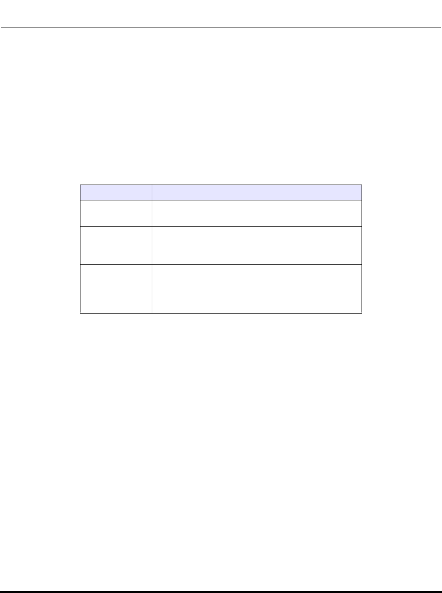
Operational Features
41-001160-03, Rev 00, Releaes 2.4 5-301
Configuring Operational Features
Server to IP Phone Download
You can populate your IP phone Directory List with server directory files. To
activate this feature, you need to add the following parameters to the
configuration files:
• directory 1: company_directory
• directory 2: my_personal_directory’
The IP phone recognizes the following characters in a Directory List:
A valid directory entry has a name, a URI number, and optional line number, and
an optional mode attribute, all separated by commas. If a line number is not
present, the entry is assigned to line 1. If a mode attribute (public or private) is not
present, the entry is assigned to "Private".
The following directory entries are considered valid:
# our company's directory
# updated 1 jan 2012
# mode = private, by default
#
joe foo bar, 123456789, 6
# line = 1, by default
# mode = private, by default
#
snidley whiplash, 000111222
# the parser ignores the COMMA # in the name
# mode = private, by default
#
"manny, jr", 093666888, 9
# the parser ignores the POUND # chars in the URI number
# mode = private, by default
#
hello dolly, "12#34#7", 2
Character Description
’#’ Pound character; any characters appearing after
the # on a line are treated as a comment
’,’ Comma character; used to separate the name,
URI number, line, and mode fields within each
directory entry.
’"’ Quotation mark; when pound and comma
characters are found between quotes in a name
field or URI number field, they are treated as
regular characters.
Draft 1

Operational Features
5-302 41-001160-03, Rev 00, Releaes 2.4
IP Phone Administrator Guide
Server to IP Phone Download Behavior
The software that reads directory files from the server, loads the file’s contents
into the phone's NVRAM when the phone is booting. Directory entries in the
NVRAM that originate from a server directory file are 'owned' by the server.
During the boot process both directory files are read, combined into a single list,
and any duplicate entries are deleted from the list. Any entries in this list that are
not already in the phone's NVRAM are added to the NVRAM and flagged as
being owned by the server.
Likewise, any entries in the NVRAM that are owned by the server, but are no
longer in one of the server's directory files, are removed from the NVRAM.
Entries made from the IP phone UI are never touched.
Directory List Limitations
The following table indicates the maximum characters for each line and field in
the Directory List.
Directory List Limitations
Maximum length of a line 255 characters
Maximum length of a name 15 characters
Maximum length of a URI 45 characters
Maximum number directory entries in the NVRAM 200 entries
Maximum number directory entries in the NVRAM
with the "public" attribute
(6757i CT only)
50 entries
Draft 1
Operational Features
41-001160-03, Rev 00, Releaes 2.4 5-303
Configuring Operational Features
Using the Directory List
Use the following procedures to access and use the Directory List.
Note: In the following procedure, the location of keys (hard keys,
softkeys, and programmable keys) on the phone are dependant on your
specific phone model. See Chapter 1, Overview, for the keys that are
specific to your phone model.
IP Phone UI
Step Action
1On the 9143i, 6753i, 6755i, 6757i, 6757i CT:
Press the DIRECTORY key to enter the Directory List.
On the 9480i, 9480i CT:
Press the Services key, and then select “Directory” from the list of options.
Note: After entering the Directory List, if no key is pressed within 3 seconds, the phone prompts you
to press the first letter in the name of the required directory entry. The phone finds and displays the
first name with this letter.
2Use the r and s to scroll through the line items in the Directory List.
To dial from an entry in the Directory List:
3 At a line item in the Directory List, pick up the handset, press the d/f key, or press a line key.
The phone automatically dials the Directory List number for you.
To add a new entry to the Directory List:
4 a Press the SAVE key or ADD NEW softkey (depending on your model phone) at the Directory List
header screen and perform step 4.
or
Press the SAVE key or ADD NEW softkey at a line item and press the DIRECTORY key again.
b Enter a phone number, name, and line number and press the SAVE key after each field entry.
Draft 1

Operational Features
5-304 41-001160-03, Rev 00, Releaes 2.4
IP Phone Administrator Guide
To edit an entry in the Directory List:
5 a At a line item in the Directory List, press the 3 key.
Note: Use the SAVE key to scroll between the number, name and line entries.
b Edit the phone number if required and press SAVE.
c Edit the name if required and press SAVE.
d Edit the line if required and press SAVE.
e Press SAVE to save the changes and exit the editing function.
To delete an entry from the Directory List:
6 a At a line item in the Directory List, press DELETE. The following prompt displays:
“DELETE again to erase this item”.
b Press DELETE again to delete the entry from the Directory List.
Note: To cancel a delete function, press the r or the s scroll keys.
To delete all entries from the Directory List:
7 a At the Directory List header, press DELETE or DELETE LIST (depending on your phone model).
The following prompt displays:
“DELETE again to erase all items”.
b Press DELETE again to delete all entries from the Directory List.
Note: To cancel a delete function, press the r or the s scroll keys.
To copy an entry from the Directory List to a speeddial key (for 9143i, and 6753i only):
8 At a line item in the Directory List, press the SAVE key.
The "Save to?" prompt displays.
Enter a number from 1 to 9 (associated with the keypad) where you want to save the item as a
speeddial.
Note: You must have a speeddial key previously configured on your phone to use this feature. To
configure a speeddial key, see your Model-specific User’s Guide.
IP Phone UI
Step Action
Draft 1

Operational Features
41-001160-03, Rev 00, Releaes 2.4 5-305
Configuring Operational Features
9 To exit the Directory List, press the DIRECTORY key again, the GOODBYE key, or the QUIT key
(depending on your specific phone model).
From the 9480i CT and 6757i CT handset:
10 a Press the Public/Private softkeys to toggle between making the new entry public or private.
Note: The entry is set to Private by default. If the entry is made Public, the entry is sent to the
handsets. A 6757i CT accepts a maximum of 50 entries with the public attribute.
b To edit an entry, use the Change softkey.
A screen displays allowing you to edit the name, phone number, and line number, as well as the
public/private setting.
c To dial a displayed entry from the Directory List, pick up the handset, press the d/f handsfree
key, or press the Dial softkey.
IP Phone UI
Step Action
Draft 1
Operational Features
5-306 41-001160-03, Rev 00, Releaes 2.4
IP Phone Administrator Guide
Downloading from the Server to the IP Phone
You can use the configuration files to download the Directory List from the
configuration server to the IP phone..
Use the following procedure to configure the download.
Downloading from the IP Phone to the Server
You can use the Aastra Web UI to download the Directory List from the IP phone
to the configuration server.
Note: You must use TFTP to download the Directory List.
Configuration Files
For specific parameters you can set in the configuration files for downloading the Directory List, see
Appendix A, the section, “Directory Settings” on page A-123.
Note: You must use TFTP to download the Directory List.
Draft 1
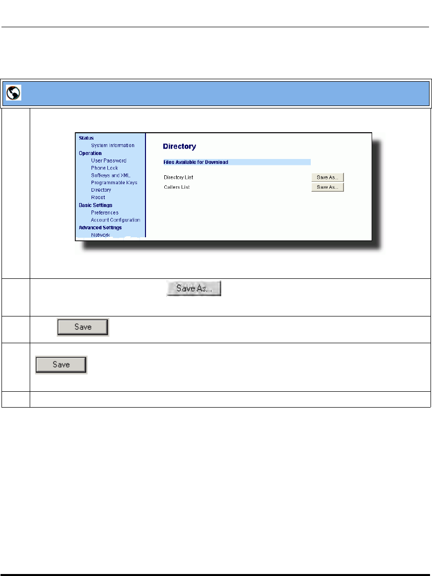
Operational Features
41-001160-03, Rev 00, Releaes 2.4 5-307
Configuring Operational Features
Use the following procedure to configure the download.
Aastra Web UI
1 Click on Operation->Directory.
2 In the Directory List field, click on .
A “File Download” message displays.
3 Click .
4 Enter the location on your computer where you want to download the Directory List and click
.
The directorylist.csv file downloads to your computer.
5 Use a spreadsheet application to open and view the Directory List.
Draft 1
Operational Features
5-308 41-001160-03, Rev 00, Releaes 2.4
IP Phone Administrator Guide
Voicemail (9480i, 9480i CT, 6755i, 6757i, and 6757i CT only)
The Voicemail feature on the 9480i, 9480i CT, 6755i, 6757i and 6757i CT IP
phones allow you to configure lines with phone numbers so the phone can dial out
to connect to a voicemail server. You associate the Voicemail numbers with the
phone numbers configured on each line (1 - 9 lines).
For each assigned Voicemail number, there can be a minimum of 0 or a maximum
of 1 Voicemail access phone number.
The Voicemail list displays a list of phone numbers assigned to the 9480i,
9480i CT, 6755i, 6757i, and 6757i CT that have registered voicemail accounts
associated with them.
The phone displays up to 99 voicemails for an account even if the number of
voicemails exceeds the limit.
Registered account numbers/URIs that exceed the length of the screen, either with
or without the voicemail icon and the message count, are truncated with an ellipse
character at the end of the number/URI string.
The end of the Voicemail list displays the number of new voicemail messages (if
any exist).
Configuring Voicemail (9480i, 9480i CT, 6755i, 6757i, and 6757i CT
only)
You configure Voicemail in the configuration files to dial a specific number to
access an existing voicemail account. The user then follows the voicemail
instructions for listening to voicemails.
Note: The Voicemail list does not display the voicemail access number.
Note: The phone must have a registered voicemail account from a server
for this feature to be enabled. When no registered voicemail accounts are
registered to the phone, the display shows "List Empty".
Draft 1
Operational Features
41-001160-03, Rev 00, Releaes 2.4 5-309
Configuring Operational Features
To configure the Voicemail feature on the 9480i/9480i CT and 6757i/6757i CT,
you must enter the following parameter in the configuration files:
• sip lineN vmail:
You can enter up to 9 Voicemail numbers associated with each of the 9 lines on the
phone.
For example:
sip line1 vmail: *97
sip line2 vmail: *95
Use the following procedure to configure voicemail using the configuration files.
Note: In the above example, the user would dial *97 to access the
voicemail account for line 1, and *95 to access the voicemail account for
line 2.
Configuration Files
For specific parameters you can set in the configuration files, see Appendix A, the section, “Voicemail
Settings” on page A-122.
Draft 1
Using Voicemail (9480i, 9480i CT, 6757i6757i CT only)
Use the following procedure to access and use voicemail.
IP Phone UI
Step Action
For the 9480i, 9480i CT, 6757i/6757i CT:
1 Press Services on the phone to display the Services menu.
2 From the Services menu, select "Voicemail".
3Use the r and s to scroll through the line items in the Voicemail List.
4 When you have selected a line item, press the d/f handsfree key, 4 Scroll Right key, or press a
line softkey to make an outgoing call using the voicemail access phone number associated with the
line for which the voicemail account is registered.
From a selected item in the Voicemail list, you can also lift the handset (go offhook) to make an
outgoing call using the voicemail access phone number.
Draft 1

Operational Features
41-001160-03, Rev 00, Releaes 2.4 5-311
Configuring Operational Features
XML Customized Services
Extensible Markup Language (XML) is a markup language much like HTML.
HTML was designed to display data and to focus on how data looks. XML was
designed to describe data and to focus on what data is.
The following are characteristics of XML:
• XML tags are not predefined. You must define your own tags.
• XML uses a Document Type Definition (DTD) or an XML Schema to
describe the data.
• XML with a DTD or XML Schema is designed to be self-descriptive
• XML is a W3C Standard Recommendation
Creating Customized XML Services on the IP Phones
The XML application for the IP phones allows users to create custom services
they can use via the phone’s keyboard and display. These services include things
like weather and traffic reports, contact information, company info, stock quotes,
or custom call scripts.
The IP phone XML application supports the following proprietary objects that
allow for the customization of the IP phone’s display.
XML Object Description
AastraIPPhoneTextMenu
(for Menu screens) Creates a numerical list of menu items on
the IP phones.
AastraIPPhoneTextScreen
(for Text screens)
AastraIPPhoneFormattedTextScreen
(for Text screens)
Creates a screen of text that wraps
appropriately.
Creates a formatted screen of text
(specifies text alignment, text size, text
static or scrolling)
AastraIPPhoneInputScreen
(for User Input screens)
AastraIPPhoneInputScreen Time
and Date Attributes
(for User Input screens)
Creates screens for which the user can
input text where applicable.
Allows you to specify US (HH:MM:SS am/
pm and MM/DD/YYYY) or International
(HH:MM:SS and DD/MM/YYYY) time/date
formats for an XML user input screen.
Draft 1
Operational Features
5-312 41-001160-03, Rev 00, Releaes 2.4
IP Phone Administrator Guide
For more information about creating customized XML applications, see
Appendix F, “Creating and Managing XML Applications.”
AastraIPPhoneDirectory
(for Directory List screen) Creates an online Directory List that a user
can browse in real-time.
AastraIPPhoneStatus
(for Idle screen) Creates a screen that displays status
messages when applicable.
AastraIPPhoneExecute
(for executing XML commands) Allows the phone to execute commands
(i.e., “reset”, “NoOp”, etc.) using XML.
AastraIPPhoneConfiguration
(for pushing a configuration to the phone) Allows the server to push a configuration to
the phone.(See page 5-316 for more
information).
AastraIPPhoneImageScreen
(Standard Bitmap Image) Creates a display with a single bitmap
image according to alignment, height, and
width specifications.
AastraIPPhoneImageMenu
(Menu Image) Creates a display with a bitmap image as a
menu. Menu selections are linked to keypad
keys (0-9, *, #).
AastraIPPhoneTextMenu (Icon Menu)
(Icon Menu Image) Creates a display that has a small icon
before each item in the menu.
XML Object Description
Draft 1

Operational Features
41-001160-03, Rev 00, Releaes 2.4 5-313
Configuring Operational Features
You can also use the following attributes/options with the XML objects to further
customize your XML applications:
Attribute/Option Description/Usage Valid Values
Beep Enables or disables a BEEP option to
indicate a status on the phone.
Use with:
XML object (See Appendix F)
Configuration files (See page 5-315)
Aastra Web UI (See page 5-315)
yes | no
Default = no
Note: This value is
case sensitive.
xml status scroll delay (config files)
Status Scroll Delay (seconds) (Web UI) Allows you to set the time delay, in
seconds, between the scrolling of each
status message on the phone.
Use with:
Configuration files (See page 5-316)
Aastra Web UI (See page 5-316)
1 to 25
Default = 5
Timeout Specifies a timeout value for the LCD
screen display.
Use with:
XML object (See Appendix F)
0, 30, 45, 60
Default =45
XML Get Timeout Specifies a timeout value, in seconds,
that the phone waits for the far side to
return a response after accepting the
HTTP GET connection.
Use with:
Configuration Files (See page 5-317)
0 to 214748364
seconds
Default =0 (never
timeout)
Draft 1

Operational Features
5-314 41-001160-03, Rev 00, Releaes 2.4
IP Phone Administrator Guide
LockIn Specifies whether or not the
information on the LCD screen stays
displayed when other events occur
(such as pressing buttons on the
keypad).
Use with:
XML object (See Appendix F)
yes | no
Default = no
CancelAction Specifies a URI that the phone
executes a GET on when the user
presses the default CANCEL key.
Use with:
XML object (See Appendix F)
Fully qualified URI
For example:
cancelAction=
http://
10.50.10.117/
ft.xml
Attribute/Option Description/Usage Valid Values
Draft 1

Operational Features
41-001160-03, Rev 00, Releaes 2.4 5-315
Configuring Operational Features
Enabling/Disabling a Beep for Status Message Displays
You can enable or disable a BEEP option using the Status Message object
(AastraIPPhoneStatus), the configuration files, or the Aastra Web UI.
When the phone receives a status message, the BEEP notifies the user that the
message is displaying.
You can use the following to enable/disable a status message beep:
•AastraIPPhoneStatus object (via XML object; see Appendix F)
•xml beep notification (via configuration files)
•XML Beep Support (via the Aastra Web UI)
Enabling the beep is an indication to the phone to sound a beep when it receives
an AastraIPPhoneStatus object. If you disable the beep, or no
AastraIPPhoneStatus object appears in the status message, then the default
behavior is no beep is heard when the object arrives to the phone.
The value set in the configuration files and Aastra Web UI override the attribute
you specify for the AastraIPPhoneStatus object.
For example, if the AastraIPPhoneStatus object has the attribute of Beep=”yes”,
and you uncheck (disable) the “XML Beep Support” in the Aastra Web UI, the
phone does not beep when it receives an AastraIPPhoneStatus object.
Setting the BEEP option in the configuration files and the Aastra Web UI applies
to the phone immediately.
Reference
For information about enabling/disabling the XML beep in the Aastra Web UI, see
“XML Beep Support” on page 5-72.
Note: For enabling/disabling a status message beep using the Status
Message object, see Appendix F, “Creating and Managing XML
Applications.”
Draft 1

Operational Features
5-316 41-001160-03, Rev 00, Releaes 2.4
IP Phone Administrator Guide
Scroll Delay Option for Status Messages
The IP phones support a scroll delay option that allows you to set the time delay,
in seconds, between the scrolling of each status message on the phone. The default
time is 5 seconds for each message to display before scrolling to the next message.
You can configure this option via the configuration files or the Aastra Web UI.
You can use the following to set the scroll delay for status messages:
•xml status scroll delay (via the configuration files)
•Status Scroll Delay (seconds) (via the Aastra Web UI)
Changes apply to the phone immediately.
Reference
For more information about configuring status scroll delay, see “Status Scroll
Delay” on page 5-74.
XML Configuration Push from the Server
The IP phones provide an XML feature that allows you to make configuration
changes to the phone that take affect immediately, without having to reboot the
phone. This feature involves creating XML scripts that push the changed
configuration parameter(s) from the server to the IP phones.
You can use the AastraIPPhoneConfiguration object in the XML scripts to
change configuration parameters or configure new parameters. However, since the
IP phone does not save new parameters created in XML scripts to the local.cfg
file, when the phone reboots, it does not save the new parameters on the phone. In
order for the phone to apply new configuration parameters, you have to enter the
parameters via the user interfaces (Telephone User Interface, Web User Interface,
or configuration files), or reapply the new parameters using the XML scripts after
every boot.
Specific configuration parameters are dynamic on the phone when pushed from
XML scripts on the server. See Appendix F, “Creating and Managing XML
Applications” for more information about XML configuration scripts and
dynamic configuration parameters.
Draft 1

Operational Features
41-001160-03, Rev 00, Releaes 2.4 5-317
Configuring Operational Features
For more information about creating XML configuration scripts and for XML
script examples, see Appendix F, “Creating and Managing XML Applications”.
Configuring the Phone to use XML
You can configure the phone to request the XML objects you create by
configuring specific parameters via the configuration files or the Aastra Web UI.
Users can access XML applications via softkeys configured on the IP phones.
The phone performs an HTTP GET on the URI configured in the Aastra Web UI
or configuration files.
You configure the following parameters for object requests:
• xml application URI
• xml application title
The xml application URI is the application you are loading into the IP phone.
The xml application title is the name of the XML application that displays on the
Services menu in the IP Phone UI (as option #4).
XML Get Timeout
The IP phone has a parameter called, “xml get timeout” that allows you to
specify a timeout value, in seconds, that the phone waits for the far side to return a
response after accepting the HTTP GET connection. If the far side accepts the
GET connection but never returns a response, it blocks the phone until it is
rebooted. If you enter a value greater than 0 for this parameter, the phone times
out and will not be blocked.
For more information about configuring this parameter, see Appendix A, the
section, “XML Settings” on page A-132.
Draft 1
Operational Features
5-318 41-001160-03, Rev 00, Releaes 2.4
IP Phone Administrator Guide
XML Push Requests
In addition to initiating a request to an XML application from a softkey, an HTTP
server can push an XML object to the phone via HTTP Post. When the phone sees
a PUSH request containing an XML object, it tries to authenticate the request. It
does so by checking the IP address or host name of the requesting host against a
list of trusted hosts (or domain names) configured via the Aastra Web UI
(parameter called XML Push Server List) or the configuration files (parameter
called xml application post list). If the request is authenticated, the XML object
is handled by the IP phone accordingly, and displays the information to the screen.
Example Configuration of XML Application
The following example shows the parameters you enter in the configuration files
to configure an XML application:
xml application URI: http://172.16.96.63/aastra/internet.php
xml application title: Aastra Telecom
xml application post list: 10.50.10.53, dhcp10-53.ana.aastra.com
Configuring for XML on the IP Phone
After creating an XML application, an administrator can configure the IP phone to
use the application using the configuration files or the Aastra Web UI.
Note: The HTTP Post must contain HTTP packets that have an "xml"
line in the message body. For more information about adding "xml" lines
in HTTP packets, see Appendix F, “Creating and Managing XML
Applications”.
Configuration Files
For specific parameters you can set in the configuration files, see Appendix A, the section, “XML Settings”
on page A-132.
Draft 1
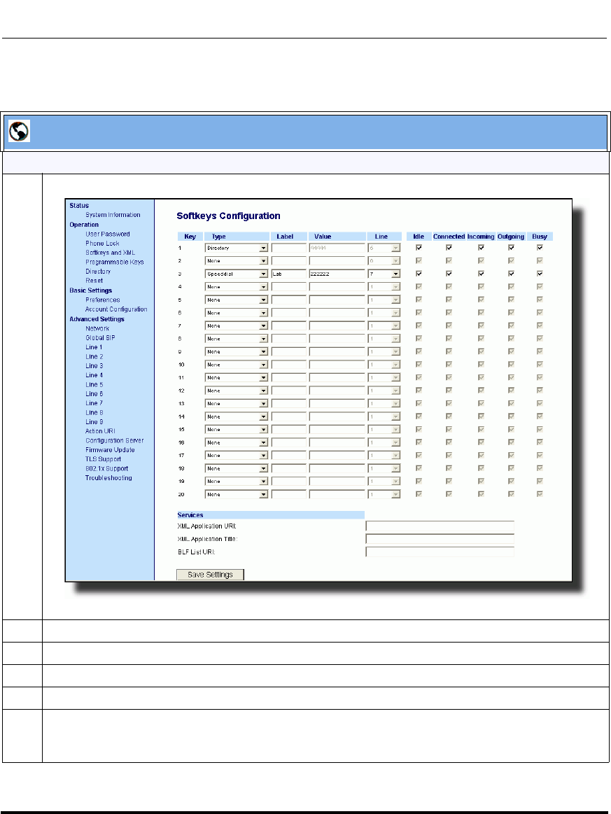
Operational Features
41-001160-03, Rev 00, Releaes 2.4 5-319
Configuring Operational Features
Aastra Web UI
For the 9480i, 9480i CT, 6755i, 6757i, 6757i CT:
1 Click on Operation->Softkeys and XML.
2 Select a key from keys 1 through 20.
3 In the "Type" field, select XML from the list box.
4 In the "Label" field, enter a label that displays on the IP phone for the softkey. For example, "XML".
5 In the "Value" field, enter the IP address or qualified domain name of the XML application.
6 In the "XML Application URI" field, enter the HTTP server path or qualified domain name of the XML
application you want to load to the IP phone. For example, you could enter an XML application called
"http://172.16.96.63/aastra/internet.php" in the applicable field.
Draft 1
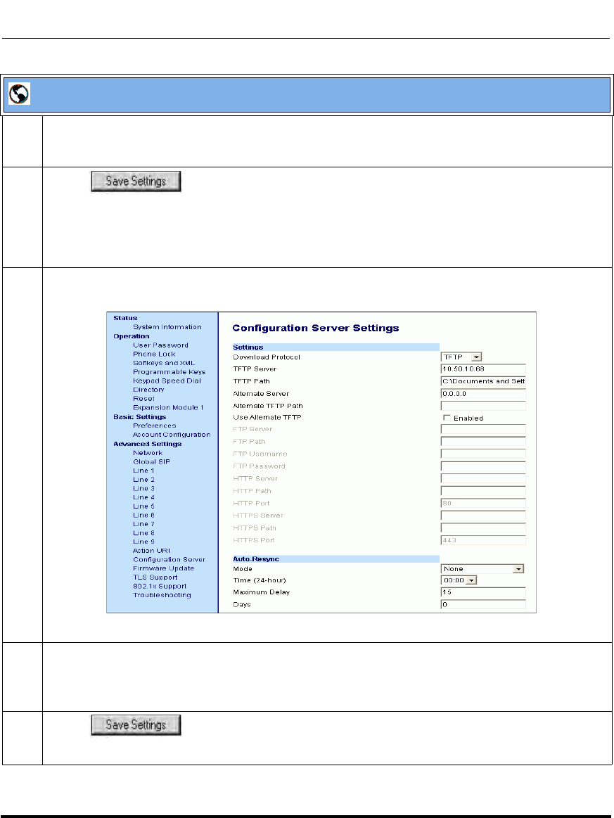
Operational Features
5-320 41-001160-03, Rev 00, Releaes 2.4
IP Phone Administrator Guide
7 In the "XML Application Title" field, enter the name of the XML application that you want to display
on the IP phone Services Menu. In the illustration above, the XML Application Title is "Aastra
Telecom".
8 Click to save your changes.
The XML application is applied to the IP phone immediately.
When the XML application is pushed to the phone via an HTTP POST, a host IP address or domain
name server is required.
9 Click on Advanced Settings->Configuration Server.
10 In the "XML Push Server List (Approved IP Addresses)" field, enter the host IP address and/or
domain name server. You can enter multiple IP address and/or domain name servers (separated by
commas). In the example in Step 8, the illustration shows a host IP address of "10.50.10.53,
10.50.10.54" in the applicable field.
11 Click to save your changes.
Note: No posting is performed if a session times out.
Aastra Web UI
Draft 1
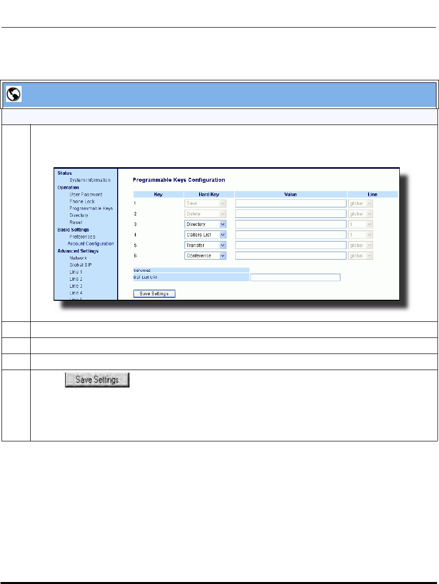
Operational Features
41-001160-03, Rev 00, Releaes 2.4 5-321
Configuring Operational Features
Aastra Web UI
For the 9143i, 6753i
1 Click on Operation->Programmable Keys.
6753i and 9143i Screen
2 For the 6753i and 9143i, select a key from keys 3 through 6.
3 In the "Hard Key" field, select XML from the list box.
4 In the "Value" field, enter the IP address or qualified domain name of the XML application.
5 Click to save your changes.
The XML application is applied to the IP phone immediately.
When the XML application is pushed to the phone via an HTTP POST, a host IP address or domain
name server is required.
Draft 1
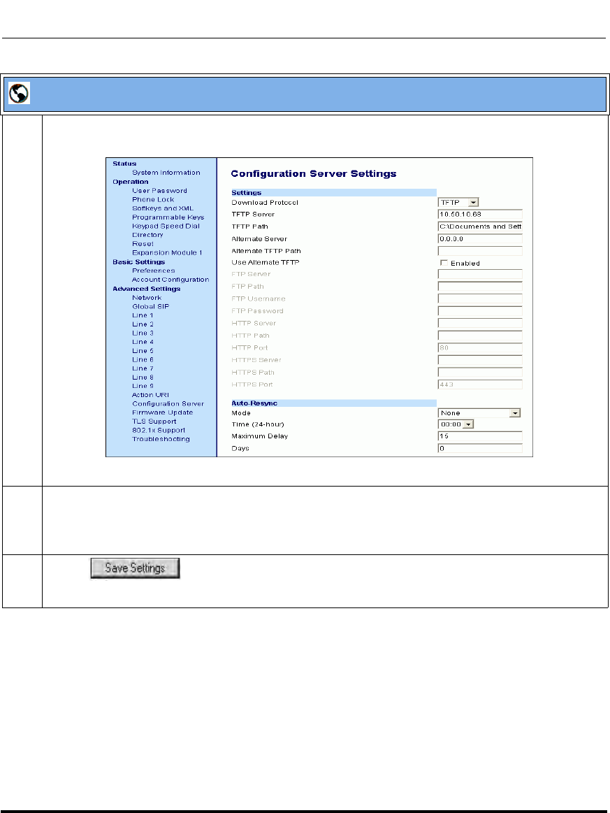
Operational Features
5-322 41-001160-03, Rev 00, Releaes 2.4
IP Phone Administrator Guide
6 Click on Advanced Settings->Configuration Server.
7In the "XML Push Server List (Approved IP Addresses)" field, enter the host IP address and/or
domain name server. You can enter multiple IP address and/or domain name servers (separated by
commas). In the example in Step 6, the illustration shows a host IP address of "10.50.10.53,
10.50.10.54" in the applicable field.
8 Click to save your changes.
Note: No posting is performed if a session times out.
Aastra Web UI
Draft 1
Operational Features
41-001160-03, Rev 00, Releaes 2.4 5-323
Configuring Operational Features
Using the XML Customized Service
After you create, save, and configure the IP phone with an XML application, the
customized service is ready for you to use.
Use the following procedure to use the XML feature on the IP phone.
IP Phone UI
Step Action
For the 9480i, 9480i CT, 6755i, 6757i, 6757i CT:
1 Press the Services key on the phone to display the Services menu.
2Select "Custom Features".
3Use the r and s to scroll through the line items in a menu-driven and directory "Custom
Features" screen.
Message services display to the screen after selecting the "Custom Features" option.
For user input services, follow the prompts as appropriate.
4 To exit from the "Custom Features" screen, press Exit.
Draft 1
Operational Features
5-324 41-001160-03, Rev 00, Releaes 2.4
IP Phone Administrator Guide
IP Phone UI
Step Action
For the 9143i, 6753i:
1 Press the programmable key configured on the phone for XML services.
A "Custom Features" screen displays.
2Use the r and s to scroll through the customized features.
3 Select a service to display the information for that customized service.
Message services display to the screen after pressing the programmable key.
For user input services, follow the prompts as appropriate.
4 To exit from the "Custom Features" screen, press the XML programmable key again.
Draft 1

Operational Features
41-001160-03, Rev 00, Releaes 2.4 5-325
Configuring Operational Features
XML Action URIs
The IP phones have a feature that allows an administrator to specify a uniform
resource identifier (URI) that triggers a GET when certain events occur. The IP
phone events that support this feature are:
The IP phones have a feature that allows an administrator to specify a uniform
resource identifier (URI) that triggers a GET when certain XML events occur. The
Action URI feature prevents the phones from hanging if the Action URIs should
fail. The phones also support transparent, non-blocking, XML post execute item
URIs.
The IP phone XML events that support this feature are defined in the following
table.
Action URI Description
Startup Specifies the URI for which the phone executes a GET on
when a startup event occurs.
Successful Registration Specifies the URI for which the phone executes a GET on
when a successful registration event occurs.
Registration Event Specifies the URI for when registration events occur or when
there are registration state changes.
Note: This action URI is not called when the same event is
repeated (for example, a timeout occurs again when
registration is already in a timeout state.)
Incoming Call Specifies the URI for which the phone executes a GET on
when an incoming call event occurs.
Outgoing Call Specifies the URI for which the phone executes a GET on
when an outgoing call event occurs.
Offhook Specifies the URI for which the phone executes a GET on
when an offhook event occurs.
Onhook Specifies the URI for which the phone executes a GET on
when an onhook event occurs.
Disconnected Specifies the URI that the phone executes a GET on, when it
transitions from the incoming, outgoing, calling, or connected
state into the idle state. For more information, see “Action URI
Disconnected” on page 5-336.
Draft 1
Operational Features
5-326 41-001160-03, Rev 00, Releaes 2.4
IP Phone Administrator Guide
The following table identifies the configurable action URI parameters in the
configuration files and the Aastra Web UI. This table also identifies the variables
that apply to specific parameters.
Action URIs and Associated Variables
XML SIP Notify Specifies the URI to be called when an empty XML SIP
NOTIFY is received by the phone. For more information, see
“XML SIP Notify Events” on page 5-339.
Poll Specifies the URI to be called every "action uri poll interval"
seconds. For more information, see “Polling Action URIs” on
page 5-334.
Poll Interval Specifies the interval, in seconds, between calls from the
phone to the "action uri poll". For more information, see
“Polling Action URIs” on page 5-334.
Note: For more information about the XML execute items, see
Appendix F, “Creating and Managing XML Applications”.
Configuration File
Parameters Aastra Web UI Parameters at
Advanced Settings->Action URI Applicable Variables
action uri startup Startup $$REMOTENUMBER$$
$$DISPLAYNAME$$
$$SIPUSERNAME$$
$$SIPAUTHNAME$$
$$INCOMINGNAME$
$$PROXYURL$$
$$LINESTATE$$
$$LOCALIP$$
$$DISPLAYNAME$$
$$CALLDURATION$$
$$CALLDIRECTION$$
action uri registered Successful Registration $$SIPUSERNAME$$
$$SIPAUTHNAME$$
$$PROXYURL$$
$$LINESTATE$$
$$LOCALIP$$
Action URI Description
Draft 1

Operational Features
41-001160-03, Rev 00, Releaes 2.4 5-327
Configuring Operational Features
Variable Descriptions
action uri registration
event Registration Event $$REGISTRATIONSTATE$$
$$REGISTRATIONCODE$$
action uri incoming Incoming Call $$REMOTENUMBER$$
$$DISPLAYNAME$$
$$SIPUSERNAME$$
$$INCOMINGNAME$
$$LINESTATE$$
$$CALLDURATION$$
$$CALLDIRECTION$$
$$LOCALIP$$
action uri outgoing Outgoing Call $$REMOTENUMBER$$
$$SIPUSERNAME$$
$$LINESTATE$$
$$LOCALIP$$
action uri offhook Offhook $$LINESTATE$$
$$LOCALIP$$
action uri onhook Onhook $$LOCALIP$$
$$CALLDURATION$$
$$CALLDIRECTION$$
$$LINESTATE$$
action uri
disconnected Disconnected $$LINESTATE$$
$$LOCALIP$$
For more information, see “Action URI
Disconnected” on page -336.
action uri xml sip notify XML SIP Notify $$LOCALIP$$
For more information, see “XML SIP Notify
Events” on page 5-339.
action uri poll Poll For more information, see “Polling Action
URIs” on page 5-334.
action uri poll interval Interval For more information, see “Polling Action
URIs” on page 5-334.
Configuration File
Parameters Aastra Web UI Parameters at
Advanced Settings->Action URI Applicable Variables
Draft 1

Operational Features
5-328 41-001160-03, Rev 00, Releaes 2.4
IP Phone Administrator Guide
The following table provides a description of each variable.
Variable Description
$$SIPUSERNAME$$ Username associated with:
• registered phone
• incoming caller
• outgoing caller
$$SIPAUTHNAME$$ Authentication name associated with:
• registered phone
$$PROXYURL$$ Proxy URL associated with:
• registered phone
$$LINESTATE$$ Current line state associated with:
• registered phone
• incoming caller
• outgoing caller
• offhook
• onhook
• disconnected
$$LOCALIP$$
Note: This variable allows for
enhanced information in call
records and billing applications.
IP Address associated with:
• registered phone
• onhook
$$REMOTENUMBER$$ Remote number associated with:
• incoming caller
• outgoing caller
$$DISPLAYNAME$$ Display name associated with:
• incoming caller
$$SIPUSERNAME$$ Username associated with:
• registered phone
• incoming caller
• outgoing caller
$$INCOMINGNAME$$ Name associated with:
• incoming caller
$$CALLDURATION$$
Note: This variable allows for
enhanced information in call
records and billing applications.
Duration of last call. This variable is associated with:
• onhook
Draft 1

Operational Features
41-001160-03, Rev 00, Releaes 2.4 5-329
Configuring Operational Features
How it works
When a startup, successful registration, incoming call, outgoing call,
offhook, or onhook call event occurs on the phone, the phone checks to see if
the event has an action URI configured. If the phones finds a URI configured, any
variables configured (in the form $$VARIABLENAME$$) are replaced with the
value of the appropriate variable. After all of the variables are bound, the phone
executes a GET on the URI. The Action URI binds all variables and is not
dependant on the state of the phone.
For example, if you enter the following string for the action uri outgoing
parameter:
action uri outgoing: http://10.50.10.140/
outgoing.pl?number=$$REMOTENUMBER$$
and you dial out the number 5551212, the phone executes a GET on:
http://10.50.10.140/outgoing.pl?number=5551212
$$CALLDIRECTION$$
Note: This variable allows for
enhanced information in call
records and billing applications.
Specifies whether the current/last call was incoming or outgoing. This
variable is associated with:
• onhook
$$REGISTRATIONSTATE$$ Specifies the state of the phone’s registration. Registration states can
be:
•registered
• unregistered
•expired
• refused
• timeout
$$REGISTRATIONCODE$$ Specifies the code generated during the registration process.
Registration code can be:
"xxx"
where xxx is the 3 digit code; for example, "403". Possible codes are:
• 001 (registration successful)
• 403 (registration failed)
Variable Description
Draft 1
Operational Features
5-330 41-001160-03, Rev 00, Releaes 2.4
IP Phone Administrator Guide
You can configure this feature via the configuration files or the Aastra Web UI.
Configuring XML Action URIs
Use the following procedures to configure XML Action URIs using the
configuration files or the Aastra Web UI.
Note: If the phone can’t find the Action URI you specify, it returns a
“NULL” response. For example,
http://10.50.10.140/outgoing.pl?number=
Configuration Files
For specific parameters you can set in the configuration files, see Appendix A, the section, “Action URI
Settings” on page A-135.
Draft 1
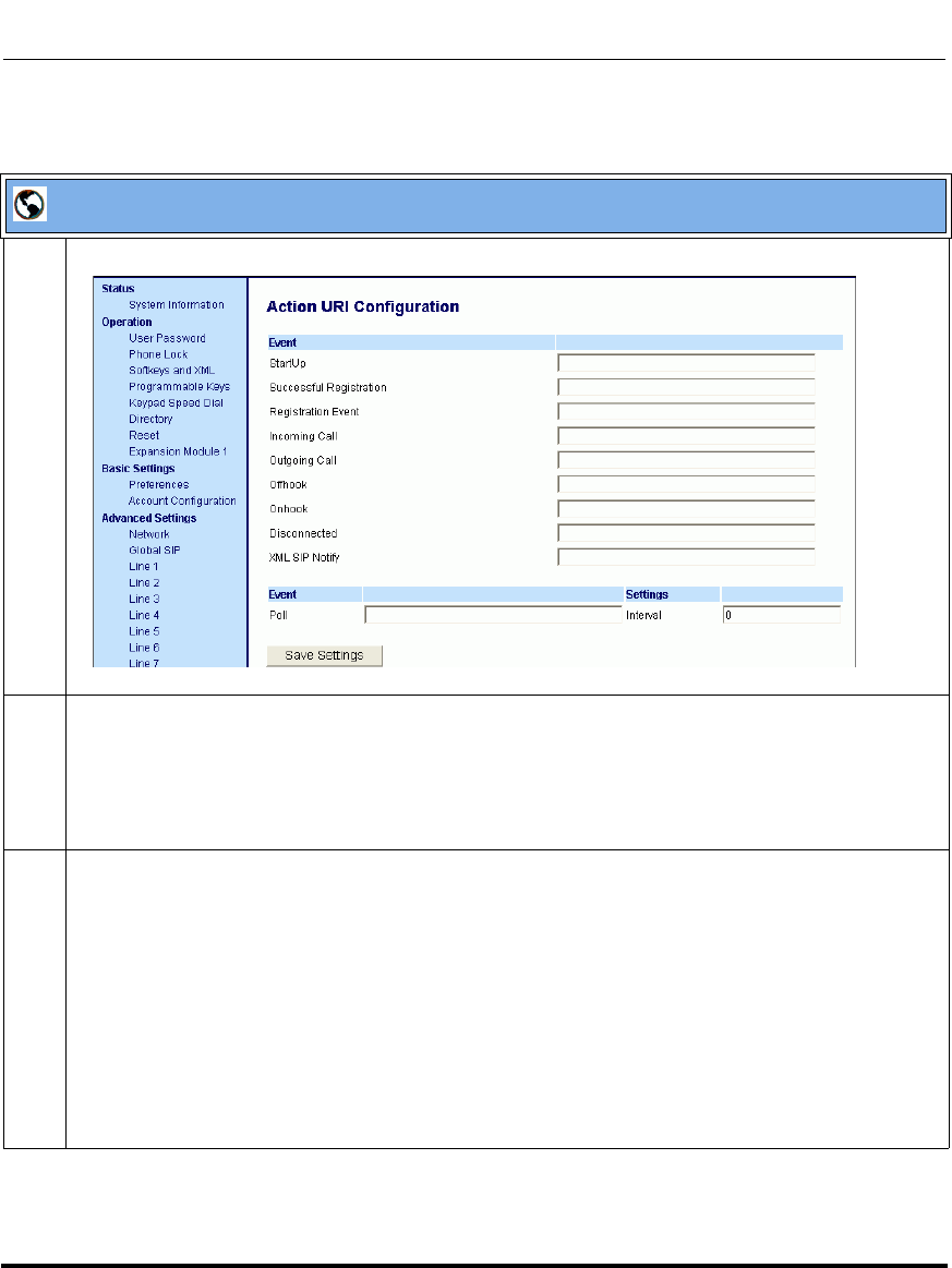
Operational Features
41-001160-03, Rev 00, Releaes 2.4 5-331
Configuring Operational Features
Aastra Web UI
1 Click on Advanced Settings->Action URI.
2 Enter an XML URI for a startup event in the “Startup” field. For example:
http://10.50.10.140/startup
This parameter specifies the URI for which the phone executes a GET on when a startup event
occurs.
3 Enter an XML URI for a successful registration in the “Successful Registration” field. For example:
http://10.50.10.14/registered.php?auth name=$$SIPAUTHNAME$$
This parameter specifies the URI for which the phone executes a GET on when a successful
registration event occurs.
Note: For a successful registration event, use the associated variables indicated in the table “Action
URIs and Associated Variables” on page 5-326.
The “Successful Registration” parameter executes on the first successful registration of each
unique line configured on the phone.
Draft 1

Operational Features
5-332 41-001160-03, Rev 00, Releaes 2.4
IP Phone Administrator Guide
4 Enter an XML URI in the “Registration Event” field, for when the phone performs registration. For
example:
http://10.30.100.39/PHPtests/
actionuri.php?action=RegEvt®state=$$REGISTRATIONSTATE$$®code=$$REGI
STRATIONCODE$$
This parameter specifies the URI that the phone executes a GET on, when a registration event
change occurs.
Note: For a registration event, use the associated variables indicated in the table “Action URIs and
Associated Variables” on page 5-326.
5 Enter an XML URI for an incoming call event in the “Incoming Call” field. For example:
http://10.50.10.140/incoming.php?number=$$REMOTENUMBER$$
This parameter specifies the URI for which the phone executes a GET on when an incoming call
event occurs.
Note: For an incoming call event, use the associated variables indicated in the table “Action URIs
and Associated Variables” on page 5-326.
6 Enter an XML URI for an outgoing call event in the “Outgoing Call” field. For example:
http://10.50.10.140/outgoing.php?number=$$REMOTENUMBER$$
This parameter specifies the URI for which the phone executes a GET on when an outgoing call
event occurs.
Note: For an outgoing call event, use the associated variables indicated in the table “Action URIs and
Associated Variables” on page 5-326.
7 Enter an XML URI for an offhook event in the “Offhook” field. For example:
http://10.50.10.140/offhook.php?state=$$LINESTATE$$
This parameter specifies the URI for which the phone executes a GET on when an offhook event
occurs.
Note: For an offhook event, use the associated variables indicated in the table “Action URIs and
Associated Variables” on page 5-326.
Aastra Web UI
Draft 1
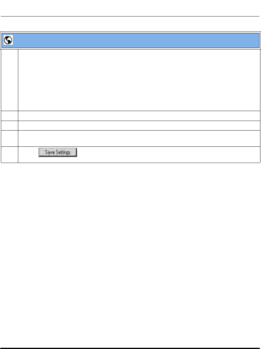
Operational Features
41-001160-03, Rev 00, Releaes 2.4 5-333
Configuring Operational Features
8 Enter an XML URI for an onhook event in the “Onhook” field. For example:
http://10.50.10.140/onhook.php?state=$$LINESTATE$$
This parameter specifies the URI for which the phone executes a GET on when an onhook event
occurs.
Note: For an onhook event, use the associated variables indicated in the table “Action URIs and
Associated Variables” on page 5-326.
9 To configure a Disconnected event, see the section, “Action URI Disconnected” on page 5-336.
10 To configure an XML SIP Notify event, see the section, “XML SIP Notify Events” on page 5-339.
11 (Optional) You can poll a URI at specific intervals on the phones. For more information about polling
Action URIs, see “Polling Action URIs” on page 5-334.
12 Click to save your changes.
Aastra Web UI
Draft 1

Operational Features
5-334 41-001160-03, Rev 00, Releaes 2.4
IP Phone Administrator Guide
Polling Action URIs
Another way to reach a phone behind a NAT/firewall is to have the phone make an
XML call at periodic intervals. An Administrator can use the action uri poll
parameter that commands the phone to perform an XML call at configurable
intervals.
An Administrator can specify the URI to be called and specify the interval
between polls using the configuration files or the Aastra Web UI. Configuration of
this feature is dynamic (no reboot required).
Configuring Polling Action URI via the Configuration Files
Use the following parameters to configure the polling Action URI on the IP
Phones.
• action uri poll
• action uri poll interval
Configuration Files
For the specific parameter you can set in the configuration files, see Appendix A, the section, “Polling Action
URI Settings” on page A-142.
Draft 1
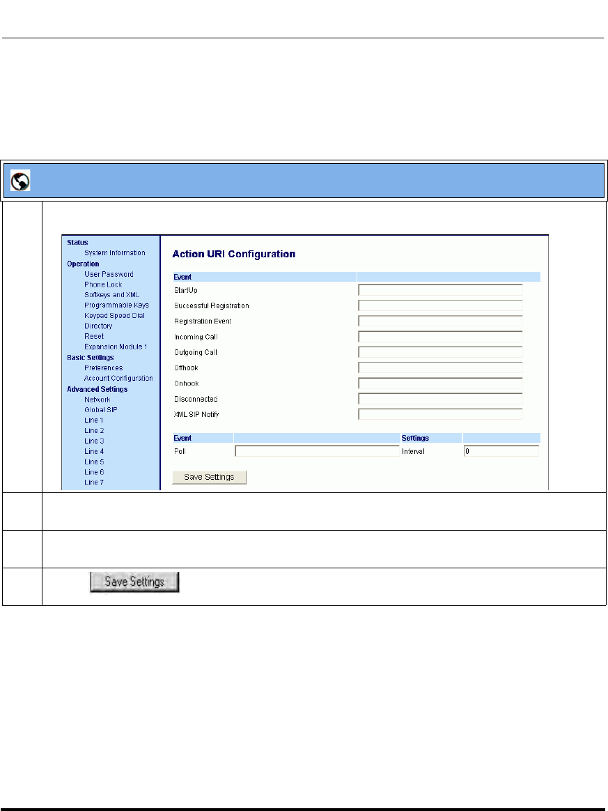
Operational Features
41-001160-03, Rev 00, Releaes 2.4 5-335
Configuring Operational Features
Configuring Polling Action URI via the Aastra Web UI
Use the following procedure to configure polling Action URI using the Aastra
Web UI.
Aastra Web UI
1 Click on Advanced Settings->Action URI.
2 In the “Poll” field, enter a URI to be called every "action uri pool interval" seconds. Enter the value in
a URI format. For example, http://myserver.com/myappli.xml.
3 In the “Interval” field, enter the interval, in seconds, between calls from the phone to the "action uri
poll". The value of “0” is disabled.
4 Click to save your changes.
Draft 1
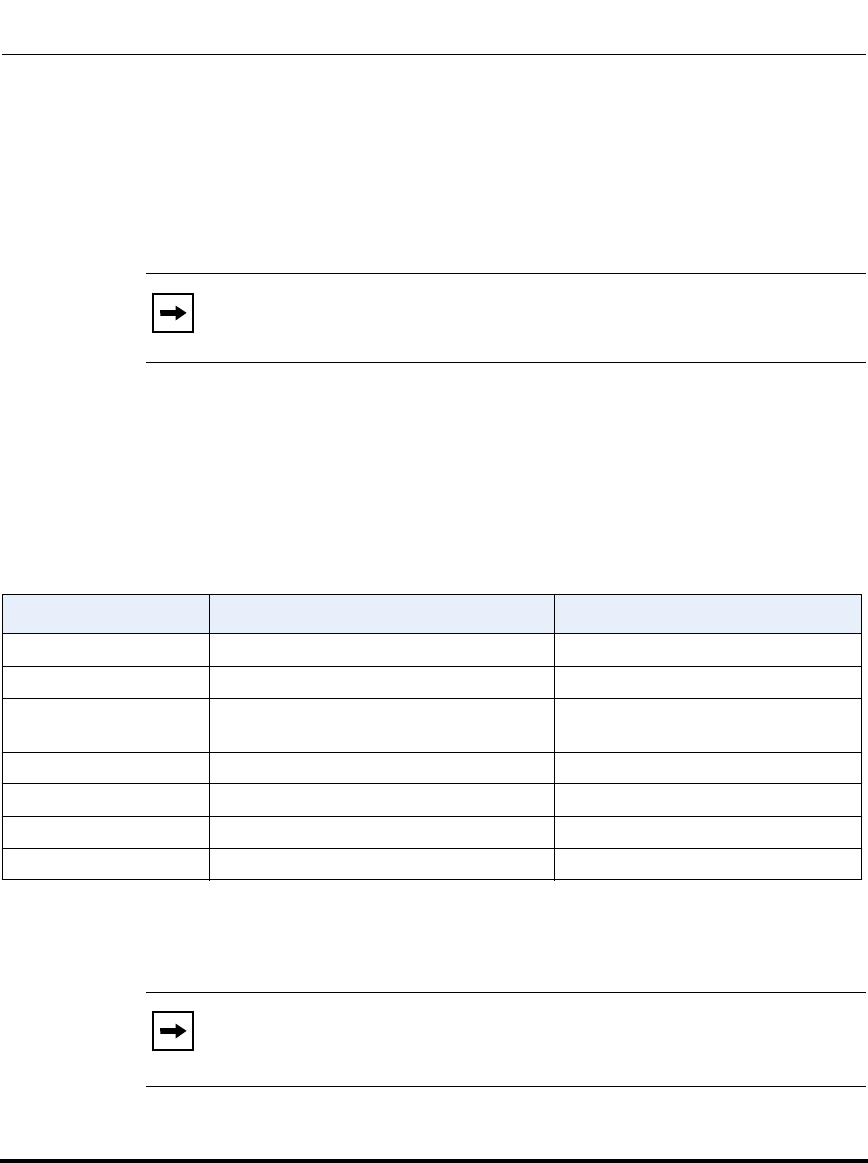
Operational Features
5-336 41-001160-03, Rev 00, Releaes 2.4
IP Phone Administrator Guide
Action URI Disconnected
The phones have a parameter, “action uri disconnected” that allow a disconnect
event to occur when the phone transitions from any active state (outgoing,
incoming, connected, or calling) to an idle state. This parameter can use the
variable “$$LINESTATE$$”.
If the Administrator enables this feature (by specifying a disconnect URI),
when a call is disconnected, the phone checks to see if the event has a
Disconnect URI configured. If the phones finds a configured URI with a
$$LINESTATE$$ variable, it replaces the $$LINESTATE$$ variable with the
appropriate line state of the current active line. After all of the variables are
bound, the phone executes a GET on the URI. The following table lists the
applicable values for the $$LINESTATE$$ variable.
The Action URI Disconnect feature allows an Administrator to determine the
reason for the disconnect if required.
Note: The $$LINESTATE$$ variable is optional and not required when
enabling the “action uri disconnected” parameter.
$$LINESTATE$$ Value Description Meaning in a Disconnected URI
IDLE Phone is idle. N/A
DIALING Phone is offhook and ready to dial. N/A
CALLING A SIP INVITE was sent but no response
was received. Error occurred during the call.
OUTGOING Remote party is ringing. Call was cancelled.
INCOMING Local phone is ringing. Call was missed or cancelled.
CONNECTED Parties are talking. Call was successful.
CLEARING Call was released but not acknowledged. N/A
Note: If you enable the Action URI Disconnect feature by specifying a
URI, the URI is called when any disconnect event occurs including an
intercom call or a conference setup.
Draft 1
Operational Features
41-001160-03, Rev 00, Releaes 2.4 5-337
Configuring Operational Features
Example
If you enter the following string on Phone A for the “action uri disconnected”
parameter:
action uri disconnected: http://fargo.ana.aastra.com/
disconnected.xml?state=$$LINESTATE$$
and then Phone A calls Phone B, Phone B answers and then hangs up, Phone A
executes a GET on:
http://fargo.ana.aastra.com/disconnected.xml?state=CONNECTED
which is what the remote server receives.
An Administrator can enable the disconnect feature using the configuration files
or the Aastra Web UI.
Configuring the Action URI Disconnected Feature
Use the following procedure to configure the Action URI Disconnected feature on
the phone.
Note: If the phone can’t find the Action URI you specify, it returns a
“NULL” response. For example,
http://fargo.ana.aastra.com/disconnected.xml?state=
Configuration Files
For specific parameters you can set in the configuration files, see Appendix A, the section, “Action URI
Settings” on page A-135.
Draft 1
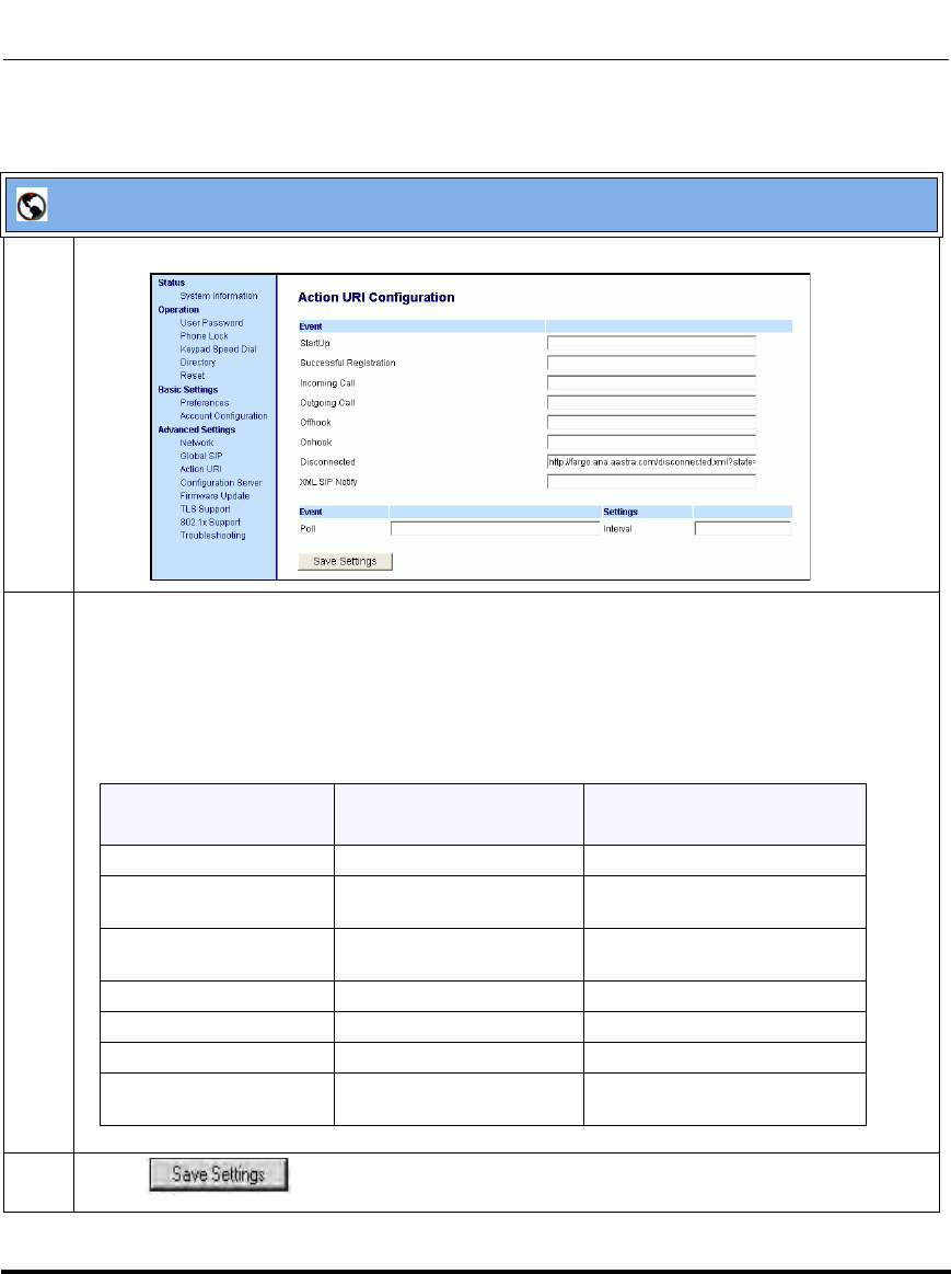
Operational Features
5-338 41-001160-03, Rev 00, Releaes 2.4
IP Phone Administrator Guide
Aastra Web UI
1 Click on Advanced Settings->Action URI->Event.
2 In the “Disconnected” field, enter a valid URI for which the phone executes a GET on, when it
transitions from the incoming, outgoing, calling, or connected state into the idle state. Leaving this
field empty disables the Action URI Disconnected feature. For example,
http://fargo.ana.aastra.com/disconnected.xml?state=$$LINESTATE$$
The following table lists the applicable values and descriptions for the $$LINESTATE$$.
3 Click to save your settings.
$$LINESTATE$$ Value Description Meaning in a
Disconnected URI
IDLE Phone is idle. N/A
DIALING Phone is offhook and ready
to dial.
N/A
CALLING A SIP INVITE was sent but
no response was received.
Error occurred during the call.
OUTGOING Remote party is ringing. Call was cancelled.
INCOMING Local phone is ringing. Call was missed or cancelled.
CONNECTED Parties are talking. Call was successful.
CLEARING Call was released but not
acknowledged.
N/A
Draft 1
Operational Features
41-001160-03, Rev 00, Releaes 2.4 5-339
Configuring Operational Features
XML SIP Notify Events
In order for an XML push to bypass the NAT/firewall, the phone supports a
proprietary SIP NOTIFY event (aastra-xml) with or without XML content. An
Administrator can enable/disable the SIP NOTIFY event using a specific
parameter in the configuration files (sip xml notify event) or the Aastra Web UI
(XML SIP Notify).
If XML content is provided in the SIP NOTIFY, it is processed directly by the
phone as it is done for an XML PUSH.
If the content is empty in the SIP NOTIFY, the phone automatically triggers a new
pre-configured action uri (action uri xml sip notify).
When the phone receives the SIP NOTIFY, the XML content is processed as any
XML object. In the above example, the phone calls http://10.30.100.39/XMLtests/
SampleTextScreen.xml after reception of the SIP NOTIFY.
Example of a SIP NOTIFY with XML Content
NOTIFY sip:200@10.30.100.103:5060 SIP/2.0
Via: SIP/2.0/UDP 10.30.100.103:5060;branch=z9hG4bK7bbc1fac;rport
From: <sip:201@10.30.100.103:5060>;tag=81be2861f3
To: Jacky200 <sip:200@10.30.100.103:5060>
Contact: <sip:201@10.30.100.103>
Call-ID: 59638f5d95c9d301
CSeq: 4 NOTIFY
Max-Forwards: 70
Event: aastra-xml
Content-Type: application/xml
Content-Length: 115
<AastraIPPhoneExecute><ExecuteItem URI="http://10.30.100.39/XMLtests/
SampleTextScreen.xml"/></AastraIPPhoneExecute>
Note: The phone supports all the current XML objects with all
the existing limitations. For example if an
AastraIPPhoneExecute is used, the embedded URI(s) can not be
HTTPS based.
Draft 1

Operational Features
5-340 41-001160-03, Rev 00, Releaes 2.4
IP Phone Administrator Guide
When the phone receives the SIP NOTIFY, it will trigger the action uri xml sip
notify parameter, if it has been previously configured using the configuration files
or the Aastra Web UI. If the action uri xml sip notify parameter is not
configured, the phone does not do anything.
On the phone side, a System Administrator can enable or disable this SIP
NOTIFY feature using the configuration files or the phone Web UI.
Also to ensure that the SIP NOTIFY is coming from a trusted source, it is
recommended that you enable the Whitelist feature (Whitelist Proxy parameter)
on the IP phone. If enabled, and the phone receives a SIP NOTIFY from a server
that is NOT on the whitelist, the phone rejects the message.
Example of a SIP NOTIFY without XML Content
NOTIFY sip:200@10.30.100.103:5060 SIP/2.0
Via: SIP/2.0/UDP 10.30.100.103:5060;branch=z9hG4bK7bbc1fac;rport
From: <sip:201@10.30.100.103:5060>;tag=81be2861f3
To: Jacky200 <sip:200@10.30.100.103:5060>
Contact: <sip:201@10.30.100.103>
Call-ID: 59638f5d95c9d301
CSeq: 4 NOTIFY
Max-Forwards: 70
Event: aastra-xml
Content-Type: application/xml
Content-Length: 0
Draft 1
Operational Features
41-001160-03, Rev 00, Releaes 2.4 5-341
Configuring Operational Features
Enabling/Disabling XML SIP NOTIFY using the Configuration Files
To enable/disable the SIP NOTIFY event, you can set the following parameter in
the configuration files:
• sip xml notify event
If the content is missing in the SIP NOTIFY message received by the phone, the
phone automatically uses the value you specify for the following parameter:
• action uri xml sip notify
Configuration Files
For the specific parameter you can set in the configuration files, see Appendix A, the section, “Polling Action
URI Settings” on page A-142.
Draft 1
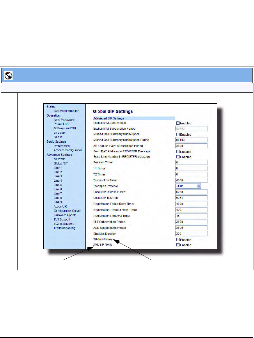
Operational Features
5-342 41-001160-03, Rev 00, Releaes 2.4
IP Phone Administrator Guide
Enabling/Disabling XML SIP NOTIFY Using the Aastra Web UI
Use the following procedure to enable/disable the XML SIP NOTIFY feature in
the Aastra Web UI.
Aastra Web UI
Enabling/Disabling the XML SIP NOTIFY Feature
1 Click on Advanced Settings->Global SIP->Advanced SIP Settings.
XML SIP Notify Parameter Enabling Whitelist Proxy is recommended
Draft 1
Operational Features
41-001160-03, Rev 00, Releaes 2.4 5-343
Configuring Operational Features
2The “XML SIP Notify" field is disabled by default. To enable this field, check the box.
This field enables or disables the phone to accept or reject an aastra-xml SIP NOTIFY message.
Note: To ensure the SIP NOTIFY is coming from a trusted source, it is recommended that you enable
the Whitelist feature (Whitelist Proxy parameter) on the IP phone. If enabled, and the phone
receives a SIP NOTIFY from a server that is NOT on the whitelist (i.e. untrusted server), the phone
rejects the message.
3 Click to save your changes.
Aastra Web UI
Draft 1
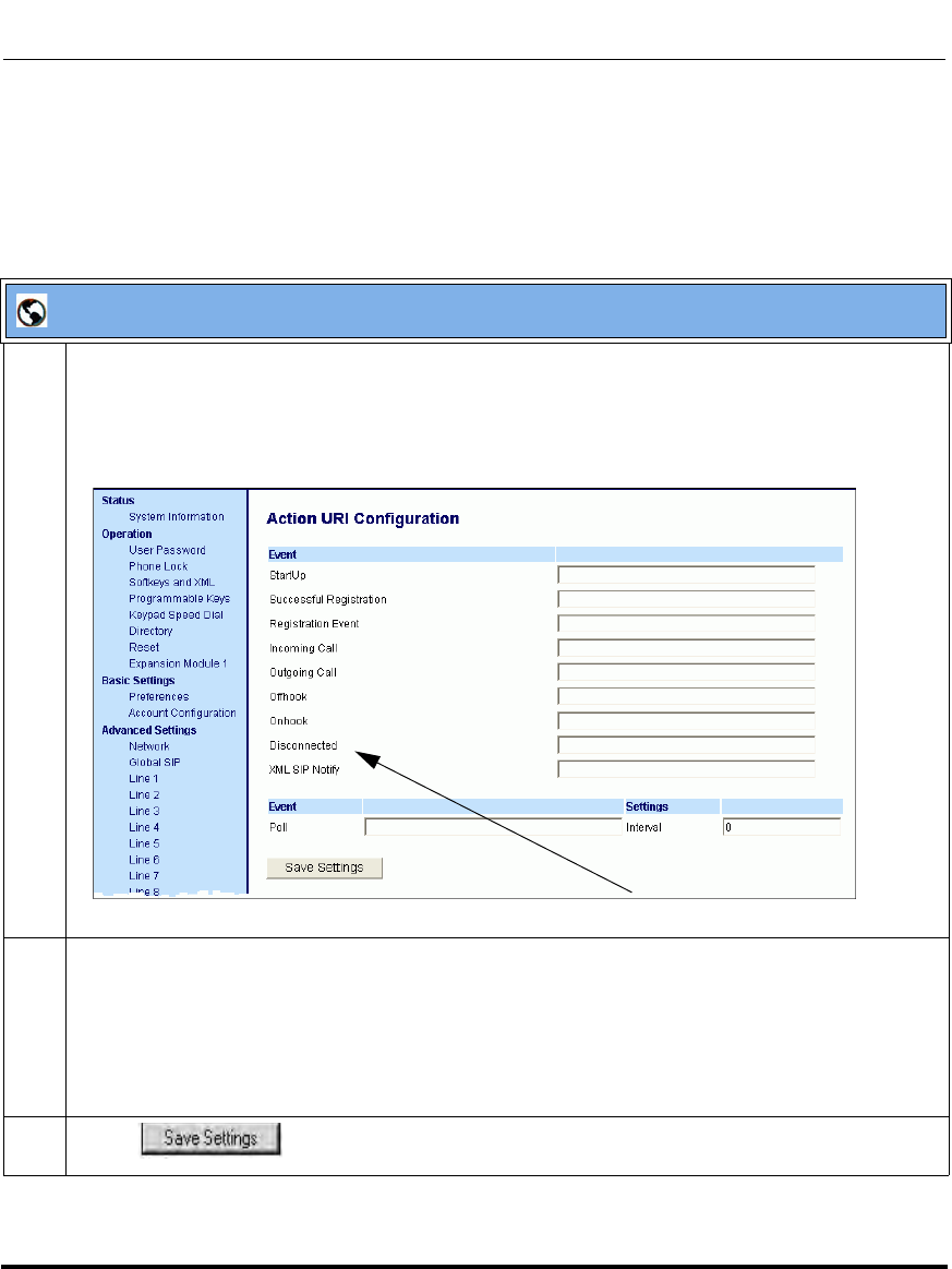
Operational Features
5-344 41-001160-03, Rev 00, Releaes 2.4
IP Phone Administrator Guide
Configuring XML SIP NOTIFY using the Aastra Web UI if an Empty
SIP NOTIFY Message Received by the Phone
Use the following procedure in the Aastra Web UI to configure the XML SIP
NOTIFY parameter when the phone receives an empty SIP NOTIFY message.
Aastra Web UI
1 If the content is missing in the SIP NOTIFY message received by the phone, the phone automatically
uses the value you specify for the Action URI XML SIP Notify parameter at the path Advanced
Settings->Action URI.
Click on Advanced Settings->Action URI.
2 Specify a URI to be called when an empty XML SIP NOTIFY is received by the phone.
For example:
http://myserver.com/myappli.xml
Note: The sip xml notify event parameter at the path Advanced Settings->Global SIP->Advanced
SIP Settings must be enabled.
3 Click to save your changes.
XML SIP Notify Parameter
Draft 1
Operational Features
41-001160-03, Rev 00, Releaes 2.4 5-345
Configuring Operational Features
XML Softkey URI
In addition to specifying variables for the Action URIs, you can also specify
variables in the XML softkey URIs that are bound when the key is pressed. These
variables are the same as those used in the Action URIs.
When an administrator enters an XML softkey URI either via the Aastra Web UI
or the configuration files, they can specify the following variables:
• $$SIPUSERNAME$$
• $$SIPAUTHNAME$$
• $$PROXYURL$$
• $$LINESTATE$$
• $$LOCALIP$$
• $$REMOTENUMBER$$
• $$DISPLAYNAME$$
• $$SIPUSERNAME$$
• $$INCOMINGNAME$$
• $$CALLDURATION$$
• $$CALLDIRECTION$$
When the softkey is pressed, if the phone finds a URI configured with variables
(in the form $$VARIABLENAME$$), they are replaced with the value of the
appropriate variable. After all of the variables are bound, the softkey executes a
GET on the URI.
Example
For example, if the administrator specifies an XML softkey with the value:
http://10.50.10.140/script.pl?name=$$SIPUSERNAME$$
This softkey executes a GET on:
http://10.50.10.140/script.pl?name=42512
assuming that the sip username of the specific line is 42512.
Note: For a description of each variable in the above list, see
“Variable Descriptions” on page 5-327.
Draft 1
Operational Features
5-346 41-001160-03, Rev 00, Releaes 2.4
IP Phone Administrator Guide
You can configure the XML softkey URI variables via the configuration files or
the Aastra Web UI.
Configuring XML Softkey URIs
Use the following procedures to configure XML Softkey URIs using the
configuration files or the Aastra Web UI.
Configuration Files
For specific parameters you can set in the configuration files, see Appendix A, the section,
“Softkey/Programmable Key/Feature Key/Expansion Module Key Parameters” on page A-192.
Draft 1
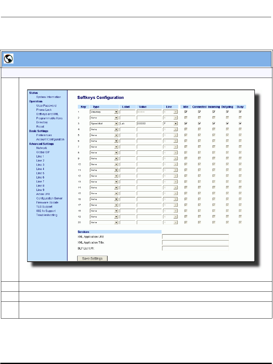
Operational Features
41-001160-03, Rev 00, Releaes 2.4 5-347
Configuring Operational Features
Aastra Web UI
For the 9480i, 9480i CT, 6755i, 6757i, 6757i CT:
1 Click on Operation->Softkeys and XML.
2 Select a key from keys 1 through 20.
3 In the "Type" field, select XML from the list box.
4 In the "Label" field, enter a label that displays on the IP phone for the XML softkey. For example,
"aastra".
Draft 1

Operational Features
5-348 41-001160-03, Rev 00, Releaes 2.4
IP Phone Administrator Guide
5 In the "Value" field, enter the URI that the phone performs a GET on when the key is pressed. For
example:
http://10.50.10.140/script.pl?name=$$SIPUSERNAME$$
Note: You can use the following variables in the URI:
• $$SIPUSERNAME$$
• $$SIPAUTHNAME$$
• $$PROXYURL$$
• $$LINESTATE$$
• $$LOCALIP$$
• $$REMOTENUMBER$$
• $$DISPLAYNAME$$
• $$SIPUSERNAME$$
• $$INCOMINGNAME$$
• $$CALLDURATION$$
• $$CALLDIRECTION$$
6 Click to save your changes.
Aastra Web UI
Draft 1
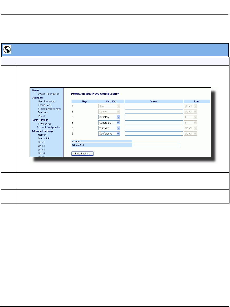
Operational Features
41-001160-03, Rev 00, Releaes 2.4 5-349
Configuring Operational Features
Aastra Web UI
For the 9143i, 6753i:
1 Click on Operation->Programmable Keys.
6753i and 9143i Screen
2 On the 9143i and 6753i, select a key from keys 1 through 6.
3 In the "Type" field, select XML from the list box.
4 On the 9143i and 6753i, in the "Label" field, enter a label that displays on the IP phone for the XML
softkey. For example, "aastra".
Draft 1
Operational Features
5-350 41-001160-03, Rev 00, Releaes 2.4
IP Phone Administrator Guide
5 In the "Value" field, enter the URI that the phone performs a GET on when the key is pressed. For
example:
http://10.50.10.140/script.pl?name=$$SIPUSERNAME$$
Note: You can use the following variables in the URI:
• $$SIPUSERNAME$$
• $$SIPAUTHNAME$$
• $$PROXYURL$$
• $$LINESTATE$$
• $$LOCALIP$$
• $$REMOTENUMBER$$
• $$DISPLAYNAME$$
• $$SIPUSERNAME$$
• $$INCOMINGNAME$$
• $$CALLDURATION$$
• $$CALLDIRECTION$$
6 Click to save your changes.
Aastra Web UI
Draft 1
Operational Features
41-001160-03, Rev 00, Releaes 2.4 5-351
Configuring Operational Features
Web Applications Keys
The IP Phones have a feature that allow a User or Administrator to assign a
pre-programmed XML-based application to a softkey, programmable key, or
expansion module key. This pre-programmed key is called, "WebApps", and is
hardcoded on the phone. Pressing this key launches an XML-based application
called, “xml.myaastra.com”. You can assign the WebApps key to any softkey,
programmable key, or expansion module key on the phone.
On the 9480i, 9480i CT, 6755i, 6757i, and 6757i CT phones, the WebApps
softkey displays on softkey 1 on the idle screen by default. You can also access
Web Apps from the Services menu on these phones.
On the 9143i and 6753i, you can access WebApps from the Services menu, or
from a configured programmable key. By default, WebApps displays in the
Services menu.
On the 6751i phone, you can access WebApps from the Services menu only.
Reference
For information on configuring a WebApps softkey or programmable key,
see Softkeys/Programmable Keys/Feature Keys/Expansion Module Keys
on page 5-141.
Note: The WebApps key is not applicable to the CT handsets.
Draft 1
Operational Features
5-352 41-001160-03, Rev 00, Releaes 2.4
IP Phone Administrator Guide
XML Key Redirection
The IP phones allow the redirecting of phone-based hard keys to XML scripts.
This allows the server to provide the phone with Redial, Transfer (Xfer),
Conference (Conf), and Intercom (Icom) key features, and the Voicemail option
feature, rather then accessing them from the phone-side. This feature allows you
to access the redirected keys and voicemail option from the server using the IP
Phone’s Services Menu. By default, the server-side keys function the same as the
phone-side key features.
The following table identifies the phone states that apply to each key
redirection.
The following URI configuration parameters control the redirection of the keys
and the voicemail option:
• redial script
• xfer script
• conf script
• icom script
• voicemail script
An Administrator can configure the XML key, redirection URI parameters using
the configuration files only.
Hard Keys/Options Redirects in
Conference (Conf) the connected state
Transfer (Xfer) the connected and dialing states
Redial all states
Intercom (Icom) all states
Voicemail all states
Notes:
1. If XML key redirection is enabled on the 6751i., the Xfer and Conf
menu items perform redirection.
2. Key remapping takes precedence over redirecting.
3. Disabling the redial, conference, or transfer features on the phone
also disables the redirection of these keys.
Draft 1

Operational Features
41-001160-03, Rev 00, Releaes 2.4 5-353
Configuring Operational Features
Configuring XML Redirection of the Redial, Xfer, Conf, and Icom
Keys, and the Voicemail Option
Use the following procedure to configure XML redirection of the Redial, Xfer,
Conf, and Icom keys, and the Voicemail option.
Options Key Redirection
(for Options Menu on all phones and Services Menu on 6751i)
The IP phones allow the redirecting of the Options Key (Options Menu on all
phones and Services Menu on the 6751i) to an XML script. This allows the server
to provide the phone with available options, rather then accessing them from the
phone-side. You access the Options Key XML script by pressing the Options Key.
You can still access the Options Menu from the phone-side by pressing and
holding the Options key to display the phone-side Options Menu.
The following URI configuration parameter controls the redirection of the
Options Key:
• options script
IMPORTANT NOTES
• If no Options URI script is configured, the local Options Menu on the phone
displays as normal.
• If you configure password access to the Options Menu, this password is
required when accessing the local Option Menu, but is not required for the
Options Key redirection feature.
• Pressing the Options Menu for redirection from the server does not interfere
with normal operations of the phone (for example, pressing the options menu
when on a call does not affect the call).
• If the phone is locked, you must unlock the phone before accessing the
Options Menu redirect feature. After pressing the Options Key, the phone
displays a screen that allows you to unlock the phone before continuing.
Configuration Files
For the specific parameters you can set in the configuration files, see Appendix A, the section, “XML Key
Redirection Settings (for Redial, Xfer, Conf, Icom, Voicemail)” on page A-237.
Draft 1

Operational Features
5-354 41-001160-03, Rev 00, Releaes 2.4
IP Phone Administrator Guide
• On the 6751i, the redirection feature works after selecting “Options” from the
Services Menu. To display the original Options Menu, press and hold the
Services key.
An Administrator can configure the XML Options Key (or Services Key on the
6751i), redirection URI parameter using the configuration files only.
Configuring XML Redirection of the Options Key (Services Key on
the 6751i)
Use the following procedure to configure XML redirection of the Options key
(Services key on 6751i).
Configuration Files
For the specific parameter you can set in the configuration files, see Appendix A, the section, “Options Key
Redirection Setting (Services key on 6751i)” on page A-239.
Draft 1
Operational Features
41-001160-03, Rev 00, Releaes 2.4 5-355
Configuring Operational Features
XML Applications and Off-Hook Interaction
A feature on the IP phone allows you to specify whether the phone is prevented
from going into the off-hook/dialing state when the handset is off-hook and the
call ends.
By default, the phone behaves as follows:
You are in a call using the handset and the phone displays an XML application.
The far-end terminates the call, and a new XML application gets pushed/pulled
onto the display. Since the handset is off-hook and in idle mode, the "offhook idle
timer" starts. When this timer expires, the phone applies dial tone and moves to
the off-hook/dialing state, which then destroys the XML application that was
being displayed.
With the “off-hook interaction” feature you can set an “auto offhook” parameter
that determines whether or not the phone is prevented from entering the off-hook/
dialing state, if the handset is off-hook and the call ends.
An Administrator can enable (allow phone to enter the off-hook dialing state) or
disable (prevent the phone from entering the off-hook dialing state) using the
“auto offhook” parameter in the configuration files only.
Configuring the Off-Hook Interaction Feature
Use the following procedure to configure the XML application and off-hook
interaction feature.
XML URI for Key Press Simulation
The Phones provide a feature that allow an XML Developer or Administrator to
define XML Key URIs that can send key press events to the phone, just as if the
physical hard key, softkey, or programmable key were pressed on the phone.
For more information about this feature, see Appendix F, the section, “XML URI
for Key Press Simulation” on page F-60.
Configuration Files
For the specific parameter you can set in the configuration files, see Appendix A, the section, “Off-Hook and
XML Application Interaction Setting” on page A-239.
Draft 1
Operational Features
5-356 41-001160-03, Rev 00, Releaes 2.4
IP Phone Administrator Guide
XML Override for a Locked Phone
The IP phones have a feature that allows a locked phone to be overridden when an
XML application is sent to the phone. This feature also allows you to still use any
softkeys/programmable key/Extension Module Keys applicable to the XML
application even though the phone is locked. However, any keys NOT associated
with the XML application cannot be used when the phone is locked.
Also, XML Get Requests override the locked feature on the phone so that any
softkey pressed by the user that initiates a Get Request continues to get sent.
To allow the overriding of the locked phone for XML applications, the System
Administrator must enter the following parameter in the configuration files:
• xml lock override
Configuring XML Override for a Locked Phone using the
Configuration Files
Configuration Files
For the specific parameter you can set in the configuration files, see Appendix A, the section, “XML Override
for a Locked Phone Setting” on page A-240.
Note: A System Administrator can also lock and unlock a remote phone
using the “lock” and “unlock” commands with the
AastraIPPhoneExecute object in an XML application. For more
information about this feature, see Appendix F, the section, “Using the
Lock and Unlock Commands” on page F-46.
Draft 1
Operational Features
41-001160-03, Rev 00, Releaes 2.4 5-357
Configuring Operational Features
Audio Transmit and Receive Gain Adjustments
The audio gain properties for the IP phone handset, headset, and speakerphone is
adjusted to reduce side-tone and echo on the local and far-end equipment. You can
adjust these settings from -10 db to +10 db to best suit your comfort level and
deployment environment by using the following parameters in the configuration
files:
• headset tx gain
• headset sidetone gain
• handset tx gain
• handset sidetone gain
• handsfree tx gain
• audio mode
The default setting for these parameters is 0 (zero).
The following table describes each parameter.
Note: Aastra Telecom recommends you leave the default of 0 (zero) as
the settings for these parameters.
Parameter Description
Headset tx gain The increased (+db) or decreased (-db) amount of signal transmitted from
the headset microphone to t he far-end party.
Headset sidetone gain The increased (+db) or decreased (-db) amount of sidetone signal from the
headset microphone to the headset speaker.
Handset tx gain The increased (+db) or decreased (-db) amount of signal transmitted from
the handset microphone to the far-end party.
Handset sidetone gain The increased (+db) or decreased (-db) amount of sidetone signal from the
handset microphone to the handset speaker.
(continued)
Draft 1
Operational Features
5-358 41-001160-03, Rev 00, Releaes 2.4
IP Phone Administrator Guide
Configuring Audio Transmit and Receive Gain Adjustments
You can configure the audio transmit and gain adjustments using the configuration
files only.
Use the following procedure to configure this feature.
Handsfree tx gain The increased (+db) or decreased (-db) amount of signal transmitted from
the base microphone to the far-end party.
Audio mode Allows you to configure how the d/f key (handsfree key) works. Audio
mode has 4 options:
0 (Speaker) - Calls can be made or received using the handset or
handsfree speakerphone and can be switched between the two modes by
pressing the d /fkey. When on speaker, you can return to using the
handset by placing the handset on the cradle and picking it up again.
1 (Headset) - Calls can be made or received using the headset. Calls can
be switched between the headset and handset by pressing the d /fkey.
2 (Speaker/Headset) - Incoming calls are sent to the speakerphone. By
pressing the d /fkey, you can switch between the handsfree
speakerphone, the headset, and the handset.
3 (Headset/Speaker) - Incoming calls are sent to the headset. By pressing
the d /fkey, you can switch between the headset, the handsfree
speakerphone, and the handset.
Configuration Files
For specific parameters you can set in the configuration files, see Appendix A, the section, “Audio Transmit
and Receive Gain Adjustment Settings” on page A-180.
Parameter Description
Draft 1

Operational Features
41-001160-03, Rev 00, Releaes 2.4 5-359
Configuring Operational Features
Centralized Conferencing (for Sylantro and Broadsoft Servers)
The IP phones include support for centralized conferencing (Ad-Hoc
conferencing) for Sylantro and Broadsoft servers. This feature provides
centralized conferencing on the SIP server (versus localized, on the phone) and
allows IP phone users to do these tasks:
• Conference two active calls together into a conference call.
• When on an active conference call, invite another party into the call.
• Create simultaneous conference calls on the same IP phone (Sylantro servers
only). For example, the IP phone user at extension 2005 could create these
two conferences, and put one conference on hold while conversing with the
other party:
— Line 1: conference together extensions 2005, 2010, and 2020.
— Line 2: conference together extensions 2005, 2011 and 2021.
When an IP phone user is connected to multiple conference calls, some
outbound proxies have maximum call “hold” time set from 30-90 seconds.
After this time, the call that is on hold is disconnected.
• Disconnect from an active conference call while allowing the other callers to
remain connected.
• Ability to create N-way conference.
• Join two active calls together into a conference call.
• Incoming or outgoing active call can join any of the existing conferences.
If the administrator does not configure centralized conferencing, then the IP
phone uses localized conferencing by default.
An Administrator can configure centralized conferencing on a global or per-line
basis using the configuration files or the Aastra Web UI.
Note: When you configure centralized conferencing globally for an IP
Phone, the global settings apply to all lines. Although, for the global
setting to work on soft lines, the user must configure the lines with the
applicable phone number.
Draft 1
Operational Features
5-360 41-001160-03, Rev 00, Releaes 2.4
IP Phone Administrator Guide
To use the centralized conferencing after it is enabled, see your Model-specific IP
Phone User Guide.
Configuring Centralized Conferencing Using the Configuration Files
You use the following parameters to configure centralized conferencing in the
configuration files:
Global Parameter
• sip centralized conf
Per-Line Parameter
sip lineN centralized conf
Configuration Files
For specific parameters you can set in the configuration files, see Appendix A, the section, “Centralized
Conferencing Settings” on page A-88.
Draft 1
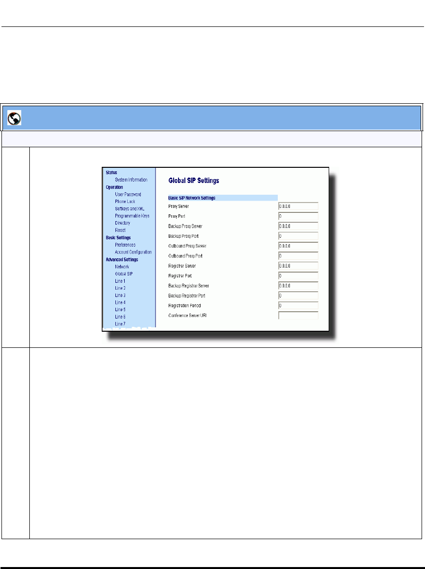
Operational Features
41-001160-03, Rev 00, Releaes 2.4 5-361
Configuring Operational Features
Configuring Centralized Conferencing Using the Aastra Web UI
Use the following procedure to configure centralized conferencing using the
Aastra Web UI.
Aastra Web UI
Global Configuration
1 Click on Advanced Settings->Global SIP Settings->Basic SIP Network Settings.
2 In the “Conference Server URI” field, do one of the following actions:
• To disable centralized conferencing on the IP phone, leave this field empty (blank).
• To enable SIP centralized conferencing on the IP phone, do one of the following actions:
— If you have specified a proxy server/registrar server, then to reach the media server via the
proxy server, set this field to one of the following:
conf (Sylantro server), or
Conference (Broadsoft server)
By setting this field to conf or Conference, you specify conf@<proxy_server _address>:
<proxy_port>. For example, if the proxy server address is 206.229.26.60 and the port used
is 10060, then by setting this parameter to conf, you are specifying the following:
conf@206.229.26.60:10060.
— To reach the media server using a different address/port than that specified by the proxy,
set this field to the following:
conf@<media_server _address>: <media_port>
Draft 1
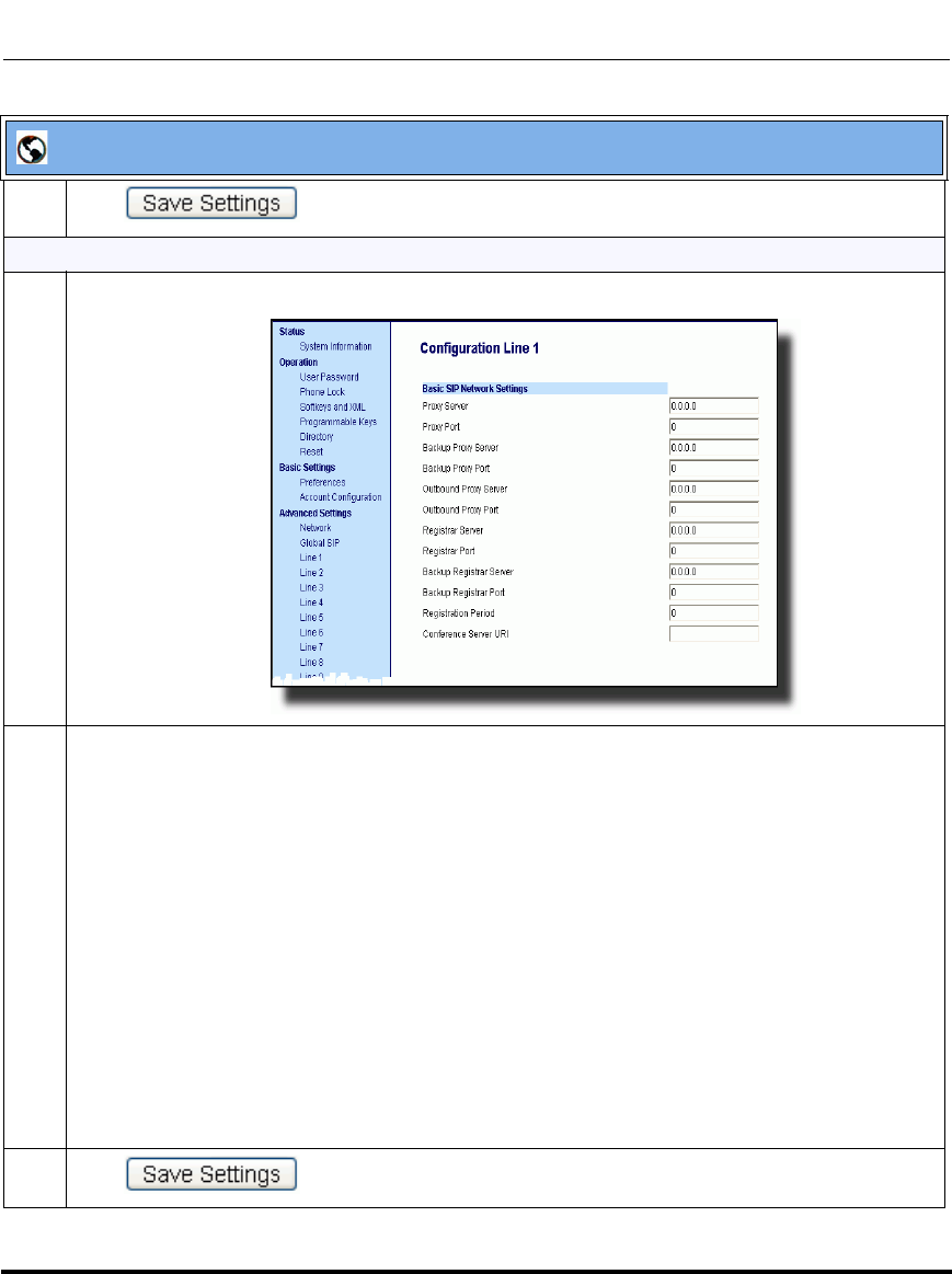
Operational Features
5-362 41-001160-03, Rev 00, Releaes 2.4
IP Phone Administrator Guide
3 Click to save your changes.
Per-Line Configuration
1 Click on Advanced Settings->Line <#>->Basic SIP Network Settings
2 In the “Conference Server URI” field, do one of the following actions:
• To disable centralized conferencing on this line, leave this field empty (blank).
• To enable SIP centralized conferencing on this line, do one of the following actions:
— If you have specified a proxy server/registrar server, then to reach the media server via the
proxy server, set this field to one of the following:
conf (Sylantro server), or
Conference (Broadsoft server)
By setting this field to conf or Conference, you specify conf@<proxy_server _address>:
<proxy_port>.
— To reach the media server using a different address/port than that specified by the proxy,
set this field to the following:
conf@<media_server _address>: <media_port>
3 Click to save your changes.
Aastra Web UI
Draft 1

Operational Features
41-001160-03, Rev 00, Releaes 2.4 5-363
Configuring Operational Features
“SIP Join” Feature for 3-Way Conference (not applicable to the 6751i)
The IP Phones support RFC 3911 which allows an additional caller to join an
active call between two parties if the caller knows the dialog information. This
feature begins a conference using a join header as described in RFC 3911.
The “SIP Join“ feature provides the following:
• Security via the whitelist (which is a feature that already exists on the phone).
• Initiates an offhook action uri when it is answered.
• Initiates an onhook action uri at call termination.
• Creates a caller list entry.
This feature is disabled by default. You can enable the “SIP Join” feature by
setting the “sip join support” parameter in the configuration files.
Limitations of the “SIP Join” Feature
The following are limitations of the “SIP Join” feature:
• Not applicable to a conference call already in progress.
• Not applicable to a CT handset that has two active calls.
• Not applicable to a phone mixing RTP.
• Allows secondary parties to join calls if they can determine the dialog
parameters. In order to provide security, it is recommended that the
Administrator configure the SIP whitelist.
• Not applicable while the active call between two parties is in the early dialog
state.
Draft 1
Operational Features
5-364 41-001160-03, Rev 00, Releaes 2.4
IP Phone Administrator Guide
Configuring the “SIP Join” Feature Using the Configuration Files
You use the following parameters to configure the “SIP Join feature in the
configuration files:
sip join support
Configuration Files
For specific parameters you can set in the configuration files, see Appendix A, the section, “SIP Join Feature
for 3-Way Conference” on page A-90.
Draft 1

Operational Features
41-001160-03, Rev 00, Releaes 2.4 5-365
Configuring Operational Features
Authentication Support for HTTP/HTTPS Download Methods, used
with Broadsoft Client Management System (CMS)
The IP phones support HTTP/HTTPS digest authentication as defined in
RFC 2617. (The HTTP client supports digest authentication; the HTTP server
does not; the HTTP server supports basic authentication). This feature allows the
phones to interoperate with Broadsoft’s CMS phone configuration tool.
Using the configuration files, you can enable/disable the following parameter to
display a LOG IN softkey which allows the HTTP/HTTPS server to perform
digest authentication:
• http digest force login - specifies whether or not to display the LOG IN
softkey on the IP Phone UI screen. Valid values are 0 (disabled) or 1
(enabled). Default is 0 (disabled).
If the “http digest force login” parameter is set to 1 (enabled), after the phone
boots, the LOG IN softkey displays on the phone’s LCD. If the user presses this
softkey, a username/password screen displays, allowing the user to enter the
configured username and password that is sent to the HTTP/HTTPS server for
digest authentication by the server. By default, username is “aastra” and
password is “aastra”. You can enter the username and password in two ways:
• Using the configuration files, you can change the default values for the
following parameters:
—http digest username - specifies the username to use for HTTP/HTTPS
digest authentication.
—http digest password - specifies the password to use for HTTP/HTTPS
digest authentication.
• By enabling the “http digest force login” parameter (setting to 1) - the phone
displays the LOG IN key so the user can enter the default username/password
via the IP Phone UI.
Draft 1
Operational Features
5-366 41-001160-03, Rev 00, Releaes 2.4
IP Phone Administrator Guide
Configuring Broadsoft CMS Support via the Configuration Files
Configure Broadsoft CMS support on the IP Phone using the following
parameters in the configuration files:
• http digest force login
• http digest username
•http digest password
Using the IP Phone when Broadsoft CMS is Enabled
If you enable the HTTP/HTTPS digest authentication feature, the phone behaves
as follows with the BroadSoft CMS tool:
1. Factory default the phone.
2. Configure the HTTP or HTTPS server (specify the HTTP or HTTPS server,
path, and port).
3. Restart the phone.
The first time the phone reboots, the phone is challenged by the server. The
phone sends the default username of “aastra” and the default password of
“aastra” to the server.
The server sends the default profile to the phone. This profile includes the
information “http digest force login: 1”.When the phone receives the profile,
it displays the “Log In” key on the IP Phone UI’s idle screen.
Configuration Files
For specific parameters you can set in the configuration files, see Appendix A, the section, “HTTP/HTTPS
Authentication Support for Broadsoft CMS” on page A-91.
Draft 1
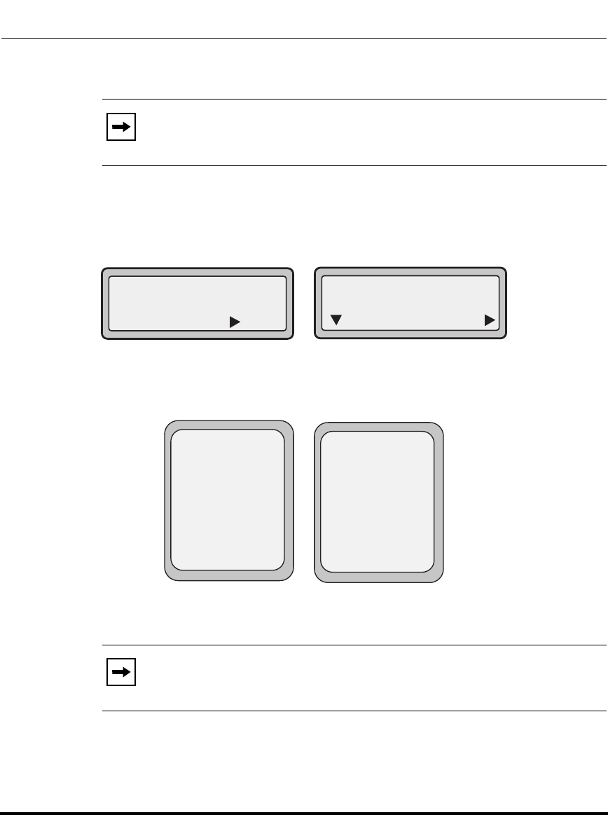
Operational Features
41-001160-03, Rev 00, Releaes 2.4 5-367
Configuring Operational Features
4. Press the “Log In" key to displays the username/password screen.
9143i, 6751i, and 6753i Login Screens
9480i, 9480i CT, 6755i, 6757i, and 6757i CT Login Screens
5. Enter a username in the “Username” field (up to 40 characters) and a
password in the “Password” field (up to 20 characters).
6. After entering the username and password, press Submit.
The phone attempts to authenticate with the server. If successful, the phone
reboots and loads the user configuration. If unsuccessful, the phone displays
“Authentication Failed”.
Note: On the 9480i, 9480i CT, 6755i, 6757i, and 6757i CT, you use the
Log In softkey to log in. On the 9143i, 6751i, and 6753i, you press the
right arrow key to log in.
Note: The “Username” and “Password” fields accept special
characters, such as, @, #, %, =, _, etc. You can also specify domain names
in the Username field (i.e., user@domain).
471348471
Log In
Tues Jan1 10:00am
Submit
Please Enter:
Username:
Next
Tues Jan1 10:00am
L1 471348471
Log In -
Username:
Password:
Please Enter:
- Backspace
- abc...
Cancel -
Submit -
Draft 1
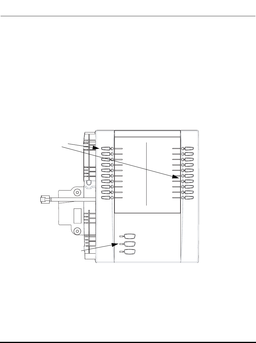
Operational Features
5-368 41-001160-03, Rev 00, Releaes 2.4
IP Phone Administrator Guide
Customizing the Display Columns on the M675i Expansion Module
The M675i Expansion Module screen displays softkeys in column format. The
function keys on the bottom left of the Module allow you to display 3 full screens
of softkeys. Each screen consists of 2 columns with the following default
headings on each page:
Page 1 "List 1" and "List 2"
Page 2 "List 3" and "List 4"
Page 3 "List 5" and "List 6"
List 1 List 2
BLF 200
Home (speeddial)
Lock/Unlock
Softkeys
Function Keys
(Press for page 1)
(Press for page 2)
(Press for page 3)
Page 1 Screen
Draft 1
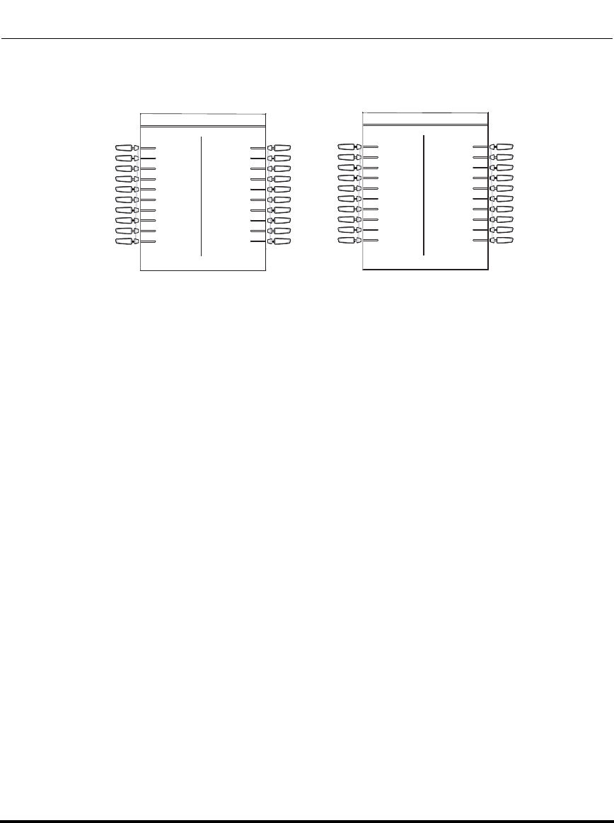
Operational Features
41-001160-03, Rev 00, Releaes 2.4 5-369
Configuring Operational Features
To use the M675i, press the function key for the page you want to display to the
LCD (page 1, page2, or page 3), and press the applicable softkey.
You can customize the headings on each M675i Expansion Module screen using
the configuration files. You use the following parameters to customize the column
headings:
Expansion Module 1 (3 pages)
• expmod1page1left
• expmod1page1right
• expmod1page2left
• expmod1page2right
• expmod1page3left
• expmod1page3right
Expansion Module 2 (3 pages)
• expmod2page1left
• expmod2page1right
• expmod2page2left
• expmod2page2right
• expmod2page3left
• expmod2page3right
List 3 List 4 List 5 List 6
Page 2 Screen Page 3 Screen
Draft 1

Operational Features
5-370 41-001160-03, Rev 00, Releaes 2.4
IP Phone Administrator Guide
Expansion Module 3 (3 pages)
• expmod3page1left
• expmod3page1right
• expmod3page2left
• expmod3page2right
• expmod3page3left
• expmod3page3right
Example
The following is an example of configuring Expansion Module 1 column
headings.
expmod1page1left: Personnel Ext
expmod1page1right: Operations Ext
expmod1page2left: Marketing Ext
expmod1page2right: Logistics Ext
expmod1page3left: Engineering Ext
expmod1page3right: Shipping Ext
Draft 1
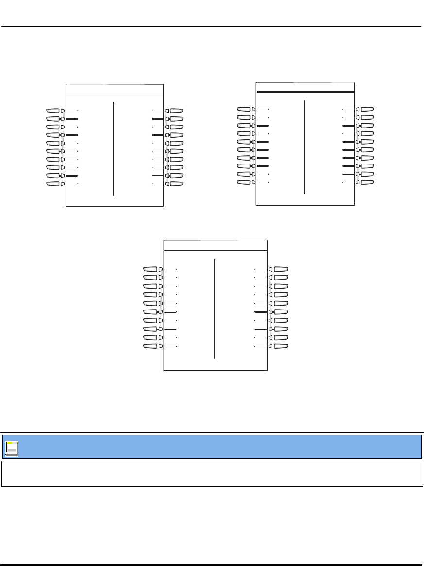
Operational Features
41-001160-03, Rev 00, Releaes 2.4 5-371
Configuring Operational Features
These settings display to the Expansion Module as shown in the following
illustrations.
Customizing the M675i Expansion Module Column Display.
Configuration Files
For specific parameters you can set in the configuration files, see Appendix A, the section,
“Customizing M675i Expansion Module Column Display” on page A-231.
Page 1 Screen
Personnel Ext Operations Ext Marketing Ext Logistics Ext
Engineering Ext Shipping Ext
Page 2 Screen
Page 3 Screen
Draft 1

Operational Features
5-372 41-001160-03, Rev 00, Releaes 2.4
IP Phone Administrator Guide
Draft 1
41-001160-03, Rev 00, Releaes 2.4 6-1
Chapter 6
Configuring Advanced
Operational Features
About this chapter
Introduction
The IP phones have advanced operational features you can configure using the
configuration files and/or the Aastra Web UI.
This chapter describes each of these features and provides procedures for
configuring each feature.
Topics
This chapter covers the following topics:
Topic Page
Advanced Operational Features page 6-3
MAC Address/Line Number in REGISTER Messages page 6-5
SIP Message Sequence for Blind Transfer page 6-7
Update Caller ID During a Call page 6-8
Boot Sequence Recovery Mode page 6-9
Auto-discovery Using mDNS page 6-10
Single Call Restriction (6757i CT and 9480i CT only) page 6-11
Missed Call Summary Subscription page 6-13
As-Feature-Event Subscription page 6-17
Draft 1
About this chapter
6-2 41-001160-03, Rev 00, Releaes 2.4
IP Phone Administrator Guide
Blacklist Duration page 6-22
Whitelist Proxy page 6-24
Transport Layer Security (TLS) page 6-26
802.1x Support page 6-31
Symmetric UDP Signaling page 6-43
Removing UserAgent and Server SIP Headers page 6-44
GRUU and sip.instance Support page 6-45
Multi-Stage Digit Collection (Billing Codes) Support (for Sylantro
Servers) page 6-46
Configurable DNS Queries page 6-49
Ignore Out of Sequence Errors page 6-51
“Early-Only” Parameter in Replaces Header RFC3891 page 6-52
Reason Header Field in SIP Message page 6-52
Topic Page
Draft 1

Advanced Operational Features
41-001160-03, Rev 00, Releaes 2.4 6-3
Configuring Advanced Operational Features
Advanced Operational Features
Description
This section provides the following information about advanced features of the IP
phones:
Feature Description
MAC Address/Line Number in REGISTER
Messages Allows you to enable or disable the sending of the MAC
address and line number from the IP phone to the call
server, in a REGISTER message.
SIP Message Sequence for Blind Transfer Allows you to enable or disable the phone to use the Blind
Transfer method available in software prior to release 1.4.
Update Caller ID During a Call Allows you to enable or disable the updating of the Caller ID
information during a call.
Boot Sequence Recovery Mode Allows you to enable or disable Web recovery mode and set
the maximum boot count on the IP phone.
Auto-discovery Using mDNS The IP phones automatically perform an auto-discovery of all
servers on a network using mDNS. When the IP phone
discovers a TFTP server, it is automatically configured by
that TFTP server.
Single Call Restriction (6757i CT and 9480i
CT only) Allows you to enable or disable a single call restriction
between the 6757i CT base unit and a call server.
Missed Call Summary Subscription Allows missed calls that have been redirected by the server,
to be incremented in the missed calls indicator on the phone
it was initially directed to.
As-Feature-Event Subscription Allows you to enable or disable a specific line on the phone
with the BroadSoft’s server-side DND, CFWD, or ACD
features.
Blacklist Duration Allows you to specifies the length of time, in seconds, that a
failed server remains on the server blacklist. The IP phone
avoids sending a SIP message to a failed server (if another
server is available) for this amount of time.
Whitelist Proxy Allows you to configure the phone to either accept or reject
call requests from a trusted proxy server.
Draft 1

Advanced Operational Features
6-4 41-001160-03, Rev 00, Releaes 2.4
IP Phone Administrator Guide
Transport Layer Security (TLS) Allows you to enable or disable the use of Persistent
Transport Layer Security (TLS).
Persistent TLS sets up the connection to the server once
and re-uses that connection for all calls from the phone. The
setup connection for Persistent TLS is established during the
registration of the phone. If the phones are set to use
Persistent TLS, and a call is made from the phone, this call
and all subsequent calls use the same authenticated
connection. This significantly reduces the delay time when
placing a call.
802.1x Support Allows you to enable or disable the 802.1x Protocol support
on the IP Phones.
Symmetric UDP Signaling Allows you to enable or disable the phone to use port 5060
to send SIP UDP messages.
Removing UserAgent and Server SIP
Headers Allows you to enable or disable the addition of the
User-Agent and Server SIP headers in the SIP stack.
Multi-Stage Digit Collection (Billing Codes)
Support (for Sylantro Servers) IP Phones support Sylantro Server features, like mandatory
and optional billing codes that require the application server
to notify the phone to collect more digits before completing
the call. The IP phone is able to collect digits in two stages to
support the billing code feature.
Configurable DNS Queries Allows you to specify the Domain Name Service (DNS)
query method to use when the phone performs a DNS
lookup.
Ignore Out of Sequence Errors Allows you to configure the phone to ignore CSeq number
errors on all SIP dialogs on the phone.
Feature Description
Draft 1
Advanced Operational Features
41-001160-03, Rev 00, Releaes 2.4 6-5
Configuring Advanced Operational Features
MAC Address/Line Number in REGISTER Messages
The IP phones can send the MAC address and line number in the REGISTER
packets making it easier for the call server when a user configures the phones via
the Aastra Web UI or the IP Phone UI. The following two configurable headers
send this information to the call server:
Aastra-Mac: <mac address>
Aastra-Line: <line number>
The MAC address is sent in uppercase hex numbers, for example,
00085D03C792. The line number is a number between 1 and 9.
The following parameters allow you to enable/disable the sending of MAC
address and line number to the call server:
• sip send mac
• sip send line
These parameters are disabled by default. The parameters are configurable via the
configuration files or the Aastra Web UI.
Configuring the MAC address/Line Number in REGISTER Message
Configuration Files
For specific parameters you can set in the configuration files for enabling/disabling MAC address and line
number, see Appendix A, the section, “Advanced Operational Parameters” on page A-233.
Draft 1
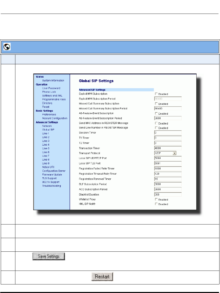
Advanced Operational Features
6-6 41-001160-03, Rev 00, Releaes 2.4
IP Phone Administrator Guide
.
Aastra Web UI
Step Action
1 Click on Advanced Settings->Global SIP->Advanced SIP Setting.
2 Enable the "Send MAC Address in REGISTER Message" field by checking the check box.
(Disable this field by unchecking the box).
3 Enable the "Send Line Number in REGISTER Message" field by checking the check box.
(Disable this field by unchecking the box).
4 Click to save your settings.
Note: The session prompts you to restart the IP phone to apply the configuration settings.
5Select Operation->Reset and click .
Draft 1

Advanced Operational Features
41-001160-03, Rev 00, Releaes 2.4 6-7
Configuring Advanced Operational Features
SIP Message Sequence for Blind Transfer
The SIP message sequence for Blind Transfer avoids the transfer target having
two simultaneous calls. Prior to release 1.4, a CANCEL message was sent to the
transfer target (if it was in a ringing state) after sending a REFER to the transferee
to complete the transfer. In the 1.4 and later releases, the CANCEL is now sent
before the REFER message.
The following parameter allows the system administrator to force the phone to use
the Blind Transfer method available in software versions prior to 1.4:
sip cancel after blind transfer
This parameter is configurable via the configuration files only.
Configuring SIP Message Sequence for Blind Transfer
Configuration Files
For the specific parameter you can set in the configuration files for enabling/disabling the blind transfer
method, see Appendix A, the section, “Blind Transfer Setting” on page A-233.
Draft 1
Advanced Operational Features
6-8 41-001160-03, Rev 00, Releaes 2.4
IP Phone Administrator Guide
Update Caller ID During a Call
It is possible for a proxy or call server to update the Caller ID information that
displays on the phone during a call, by modifying the SIP Contact header in the
re-INVITE message. The phone displays the updated name and number
information contained within the Contact header.
The following parameter allows the system administrator to enable or disable this
feature:
sip update callerid:
This parameter is configurable via the configuration files only.
Configuring Update Caller ID During a Call
Configuration Files
For the specific parameter you can set in the configuration files for enabling/disabling the update of caller ID
during a call, see Appendix A, the section, “Update Caller ID Setting.” on page A-233.
Draft 1
Advanced Operational Features
41-001160-03, Rev 00, Releaes 2.4 6-9
Configuring Advanced Operational Features
Boot Sequence Recovery Mode
You can force the IP phone into recovery mode by pressing the 1 and # keys
during boot up when the logo displays. This feature is enabled by default on the IP
phone.
You can disable this feature using the following parameter in the configuration
files:
• force web recovery mode disabled
Valid values for this parameter are 0 (false) and 1 (true). Default is 0 (false).
A boot counter increments after each faulty boot. When the counter reaches a
predetermined value, it forces Web recovery mode. The counter is reset to zero
upon a successful boot.
The predetermined value is set using the following parameter in the configuration
files:
• max boot count
A zero (0) value disables this feature. The default value is 10.
You can configure the boot sequence recovery mode parameters using the
configuration files only.
Configuring Boot Sequence Recovery Mode
Configuration Files
For the specific parameters you can set in the configuration files for boot sequence recovery mode, see
Appendix A, the section, “Boot Sequence Recovery Mode Settings.” on page A-234.
Draft 1
Advanced Operational Features
6-10 41-001160-03, Rev 00, Releaes 2.4
IP Phone Administrator Guide
Auto-discovery Using mDNS
The IP phones can perform an auto-discovery of all servers on a network using
mDNS. When the IP phone discovers a TFTP server, it is automatically
configured by that TFTP server.
An unconfigured phone (phone right out of the box) added to a network, attempts
to auto-discover a configuration server on the network without any end-user
intervention. When it receives DHCP option 66 (TFTP server), it automatically
gets configured by the TFTP server.
An already configured phone (either previously configured by auto-discovery or
manually configured) added to a network, uses its predefined configuration to
boot up.
Notes:
1. Configuration parameters received via DHCP do not constitute
configuration information, with the exception of a TFTP server.
Therefore, you can plug a phone into a DHCP environment, still use the
auto-discovery process, and still allow the use of the TFTP server
parameter to set the configuration server.
2. DHCP option 66 (TFTP server details) overrides the mDNS phase of
the auto-discovery. Therefore, the DHCP option takes priority and the
remaining process of auto-discovery continues.
3. As the phone performs auto-discovery, all servers in the network
(including the TFTP server), display in the phone window. However, only
the server configured for TFTP automatically configures the phone.
Draft 1

Advanced Operational Features
41-001160-03, Rev 00, Releaes 2.4 6-11
Configuring Advanced Operational Features
Single Call Restriction (6757i CT and 9480i CT only)
On the 6757i CT and 9480i CT, an administrator can enable or disable a single
call restriction between the 6757i CT and 9480i CT base unit and a call server.
When this feature is enabled (set to 1), you can make separate active calls from
the 6757i CT and 9480i CT base unit and from the cordless handset. If this feature
is disabled (set to 0), only one call can be active at a time either from the base unit
or from the handset. When this feature is disabled, and you make an active call on
either the base unit or the handset, any other attempt to make an active call is put
on hold. Also, when this feature is disabled, more than one call can negotiate
complex audio codecs since only a single call is decoding audio at a time.
You can configure this feature via the configuration files or the Aastra Web UI.
Configuring Single Call Restriction.
Configuration Files
For the specific parameters you can set in the configuration files for single call restriction on the 6757i CT
and 9480i CT, see Appendix A, the section, “Single Call Restriction Setting” on page A-235.
Draft 1
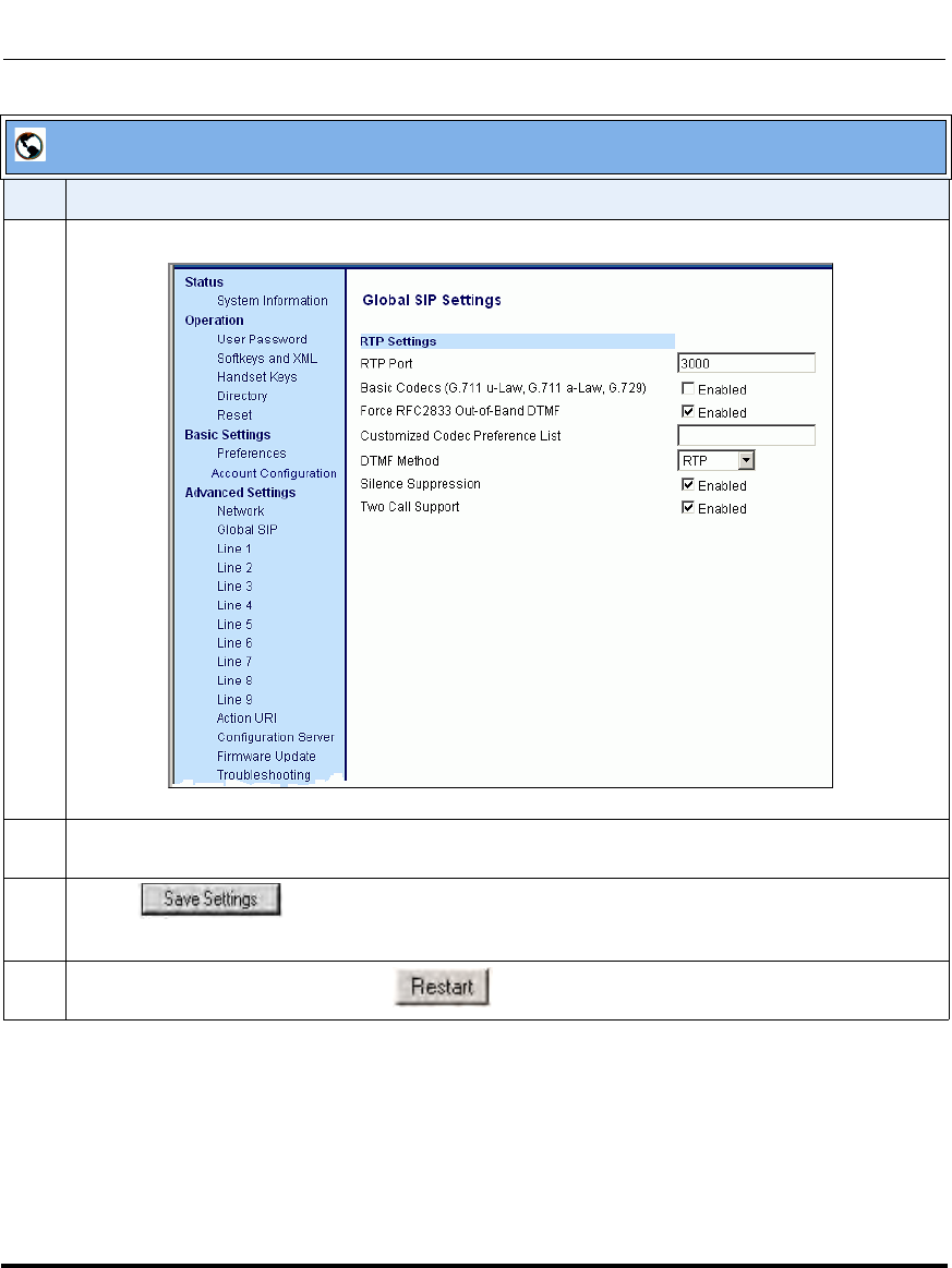
Advanced Operational Features
6-12 41-001160-03, Rev 00, Releaes 2.4
IP Phone Administrator Guide
Aastra Web UI
Step Action
1 Click on Advanced Settings->Global SIP->RTP Settings.
2 Enable the "Two Call Support" field by checking the check box.
(Disable this field by unchecking the box).
3 Click to save your settings.
Note: The session prompts you to restart the IP phone to apply the configuration settings.
4Select Operation->Reset and click .
Draft 1

Advanced Operational Features
41-001160-03, Rev 00, Releaes 2.4 6-13
Configuring Advanced Operational Features
Missed Call Summary Subscription
The “Missed Call Summary Subscription” feature allows missed calls that have
been redirected by the server, to be incremented in the missed calls indicator on
the phone it was initially directed to. This feature is called the Missed Call
Summary Subscription and can be set with a timer that allows the phone to use the
feature for a period of time before the timer expires. For this feature to work, you
must configure voicemail on the phone that the call was initially directed to.
For example, phones A, B, and C are connected to the server. You configure the
server to direct calls coming into phone B (which has voicemail configured) to be
forwarded to phone C. When phone A calls phone B, the server forwards the call
to phone C. With this feature, phone B receives notification from the server that
the call was forwarded and the missed calls indicator is incremented on phone B.
An Administrator can configure this feature on a global or per-line basis, using the
configuration files or the Aastra Web UI.
3KRQ H$
3KRQH%
3KRQH&
$FDOOV% %IRZDUGVFDOOWR&
0LVVHGFDOOVLQGLFDWRULQFUHPHQWVRQSKRQH%
1RWH
9RLFHPDLOPXVWEHFRQILJXUHGRQSKRQH%
Draft 1

Advanced Operational Features
6-14 41-001160-03, Rev 00, Releaes 2.4
IP Phone Administrator Guide
Configuring Missed Call Summary Subscription using the
Configuration Files
In addition to enabling/disabling the Misses Call Summary Subscription, You can
also configure the amount of time, in seconds, that the phone uses this feature.
The timer is configurable on a global basis only.
You use the following parameters to configure Missed Call Summary
Subscription feature on a global basis:
Global Parameters
• sip missed call summary subscription
• sip missed call summary subscription period
Use the following parameters to configure Missed Call Summary Subscription
feature on a per-line basis:
Per-Line Parameter
• sip lineN missed call summary subscription
Configuration Files
For the specific parameters you can set in the configuration files for Missed Call Summary Subscription, see
Appendix A, the section, “Missed Call Summary Subscription Settings” on page A-101.
Draft 1
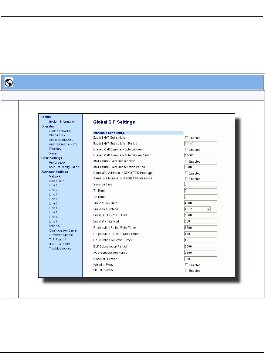
Advanced Operational Features
41-001160-03, Rev 00, Releaes 2.4 6-15
Configuring Advanced Operational Features
Configuring Missed Call Summary Subscription using the
Aastra Web UI
Use the following procedure to configure the Missed Call Summary Subscription
feature using the Aastra Web UI.
Aastra Web UI
Global Configuration
1 Click on Advanced Settings->Global SIP->Advanced SIP Settings.
Draft 1
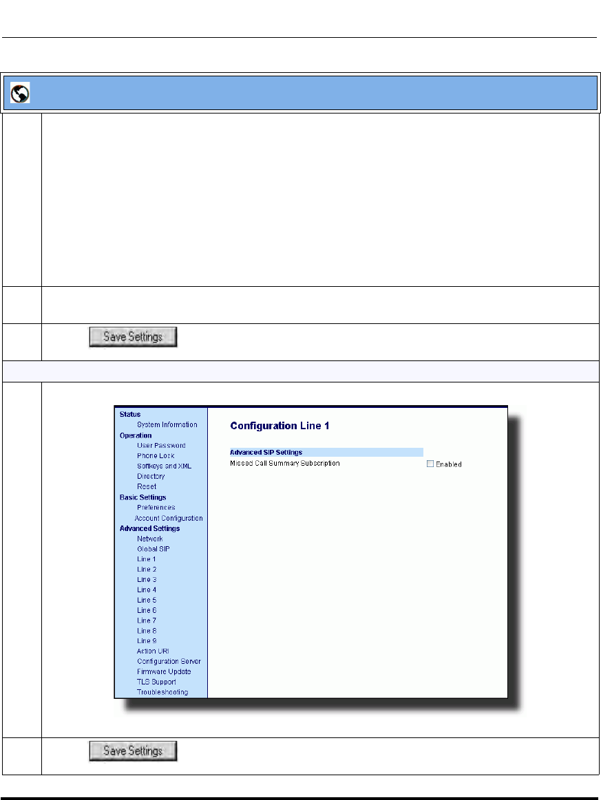
Advanced Operational Features
6-16 41-001160-03, Rev 00, Releaes 2.4
IP Phone Administrator Guide
2The "Missed Call Summary Subscription" field is disabled by default. To enable this field, check
the box.
This feature allows missed calls that have been redirected by the server, to be incremented in the
missed calls indicator on the phone it was initially directed to. For example, phones A, B, and C are
connected to the server. You configure the server to direct calls coming into phone B (which has
voicemail configured) to be forwarded to phone C. When phone A calls sip missed call summary
subscription parameter, phone B receives notification from the server that the call was forwarded
and the missed calls indicator is incremented on phone B.
Note: You must configure voicemail on the phone that the call was initially directed to (phone B in the
above example).
3The "Missed Call Summary Subscription Period" field is enabled with a default value of 86400. To
disable this field, enter zero (0), or leave the field blank.
4 Click to save your changes.
Per-Line Configuration
1 Click on Advanced Settings->Line <N>->Advanced SIP Settings.
2 Click to save your changes.
Aastra Web UI
Draft 1
Advanced Operational Features
41-001160-03, Rev 00, Releaes 2.4 6-17
Configuring Advanced Operational Features
As-Feature-Event Subscription
The IP phones support server-side Do Not Disturb (DND), Call Forward
(CFWD), and Automatic Call Distribution (ACD) feature events.This feature is
called “as-feature-event” and works with the DND, CFWD, and ACD keys.
This feature is configurable using the configuration files or the Aastra Web UI.
How it Works on the Phone UI
When you enable the “as-feature-event” on the phone, AND you activate a DND,
CFWD, and/or ACD key, pressing the key performs as follows:
• If the key is configured for an account on the phone, the server applies DND,
CFWD or ACD to that account. (For information about CFWD and DND
account configuration, see Chapter 3, the section, “Account Configuration”
on page 3-35).
• If the key is “custom” configured, a screen displays on the phone allowing the
user to choose the account to apply DND or CFWD. (For information about
CFWD and DND custom configuration, see Chapter 3, the section, “Account
Configuration” on page 3-35).
• A solid “Message Waiting Indicator” (MWI) indicates if one line/account has
DND or CFWD enabled, and the LED next to the DND/CFWD key is ON. A
status displays on the LCD that indicates the status of the line in focus (for
example, the status of CFWD could be “Call Forward Busy” (CFWDB) or
“Call Forward No Answer” (CFWDNA).
Notes:
1. The 6751i supports server-side DND and CFWD only.
2. The DND, CFWD, and ACD server-side feature is not applicable to
the CT handset.
Note: If the ACD key is configured on the phone, and the
“as-feature-event” is not enabled, the phones uses the ACD icons and
LED behavior from a Sylantro server instead.
Draft 1
Advanced Operational Features
6-18 41-001160-03, Rev 00, Releaes 2.4
IP Phone Administrator Guide
When you press the DND, CFWD, or ACD key, only one attempt is made to
enable/disable the “as-feature-event” feature on the server. The message “Trying”
displays on the phone’s LCD after pressing the key. If the attempt is successful,
the idle screen displays. If the attempt is unsuccessful, the message “Failed”
displays. The user can press the softkey again to re-attempt the feature if required.
The following screen displays on the IP Phone UI for server-side call forwarding:
For server-side ACD, when you press the ACD softkey, the screen that displays is
dependant on the state of the ACD subscription. Possible state for ACD are::
•Logged Out - User has the option of logging in.
•Logged In - User has the option of logging out or making the phone
unavailable.
•Unavailable - User has the option of logging out or making the phone
available.
ACD Screen for 9143i, 6751i, 6753i
ACD Screen for 9480i, 9480i CT, 6755i, 6757i, and 6757i CT
Call Forward
Mode: CFA Done
Next
Log In
ACD
Logged Out
Log Out
ACD Logged In
Unavail
Log Out
ACD Unavailable
Avail
Logged Out
ACD
- Log In
Cancel -
Logged In
ACD
- Log Out
- Unavailable Cancel -
Unavailable
ACD
- Log Out
- Available Cancel -
Draft 1
Advanced Operational Features
41-001160-03, Rev 00, Releaes 2.4 6-19
Configuring Advanced Operational Features
Configuring As-Feature-Event Subscription Using the Configuration
Files
If the phone-side features of the DND, CFWD, and ACD keys are enabled, the
phone uses the existing parameter values for these keys. If the server-side features
are enabled, the phone saves the state of the features from the server on the phone.
Use the following parameters to enable/disable the server-side “as-feature-event”
on the IP Phone:
• sip lineN as-feature-event subscription
• sip as-feature-event subscription period
Note: IMPORTANT!
If DND and CFWD are configured to use “Account” mode on the IP
Phone, pressing the DND and CFWD keys apply to the account in focus
as described in Chapter 3, the section, “Account Configuration” on
page 3-35.
If ACD is configured on the phone, the ACD softkey applies to the line
for which the key is configured. The ACD softkey must be configured for
the first line of an account. For example, if account 2 has line 3 and line 4
you must configure the ACD softkey for line 3.
Configuration Files
For the specific parameters you can set in the configuration files, see Appendix A, the section,
“As-Feature-Event Subscription Settings” on page A-104.
Draft 1
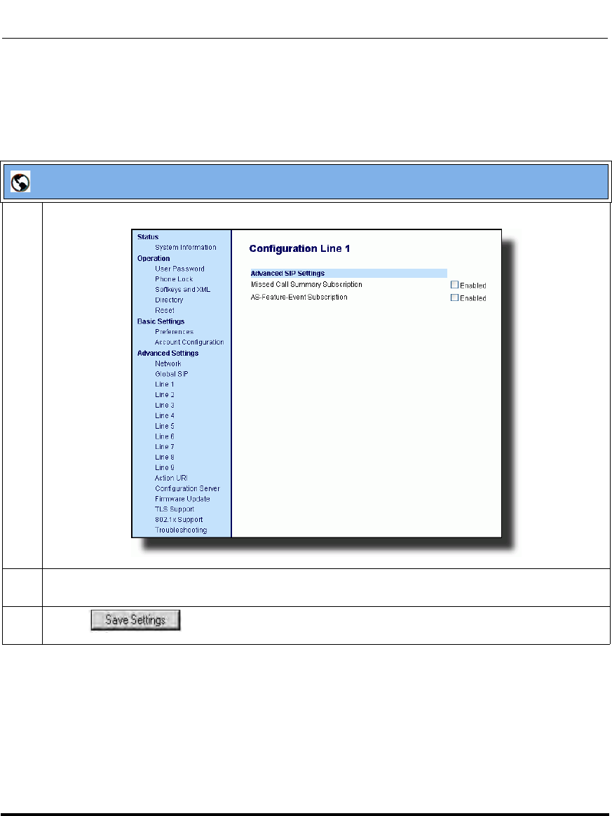
Advanced Operational Features
6-20 41-001160-03, Rev 00, Releaes 2.4
IP Phone Administrator Guide
Configuring As-Feature-Event Subscription Using the Aastra Web UI
Use the following procedure to enable/disable the server-side “as-feature-event”
on the IP Phone using the Aastra Web UI.
Aastra Web UI
1 Click on Advanced Settings->LineN->Advanced SIP Settings.
2 In the “Advanced SIP Settings” section, enable the "As--Feature-Event Subscription" field, by
checking the check box. (Disable this field by unchecking the box).
3 Click to save your changes.
Draft 1
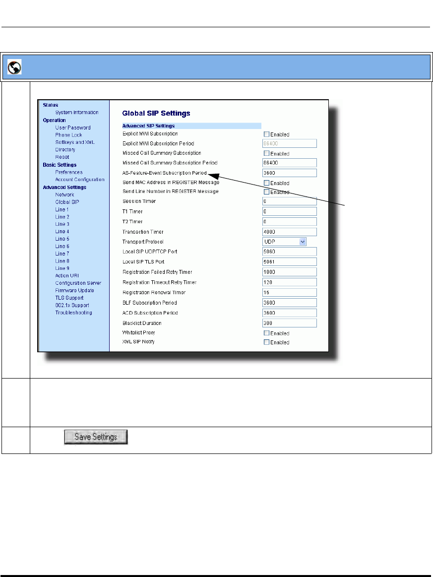
Advanced Operational Features
41-001160-03, Rev 00, Releaes 2.4 6-21
Configuring Advanced Operational Features
4 Click on Advanced Settings->Global SIP->Advanced SIP Settings.
5 In the “Advanced SIP Settings” section, in the “As-Feature-Event Subscription Period” field, enter
the amount of time, in seconds, that the phone waits after sending a SUBSCRIBE, to receive a
NOTIFY response from the server side.
Default is 3600. Valid values are
6 Click to save your changes.
Aastra Web UI
As-Feature-Event
Subscription
Period
Draft 1
Advanced Operational Features
6-22 41-001160-03, Rev 00, Releaes 2.4
IP Phone Administrator Guide
Blacklist Duration
The Blacklist Duration feature helps to reduce unnecessary delays during proxy/
registrar server failures, caused by the IP phone repeatedly sending SIP messages
to a failed server. If you enable this feature, then whenever the IP phone sends a
SIP message to a server, and does not get a response, the phone automatically
adds the server to the blacklist. The IP phone avoids sending messages to any
servers on the blacklist. If all servers are on the blacklist, then the IP phone
attempts to send the message to the first server on the list.
You can specify how long failed servers remain on the blacklist in the IP phone’s
configuration file or in the Aastra Web UI. The default setting is 300 seconds. If
you set the duration to 0 seconds, then you disable the blacklist feature.
Configuring Blacklist Duration Using the Configuration Files
Use the following parameter to configure the Blacklist Duration in the
configuration files:
• sip blacklist duration
Configuration Files
For the specific parameters you can set in the configuration files for setting Blacklist Duration, see Appendix
A, the section, “Blacklist Duration Setting” on page A-236.
Draft 1
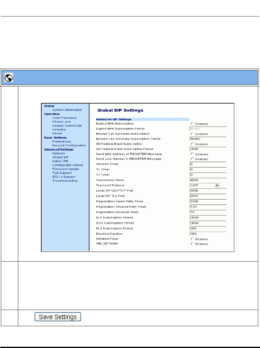
Advanced Operational Features
41-001160-03, Rev 00, Releaes 2.4 6-23
Configuring Advanced Operational Features
Configuring a Server Blacklist Using the Aastra Web UI
You use the following procedure to configure Blacklist Duration using the Aastra
Web UI.
Aastra Web UI
1 Click on Advanced Settings->Global SIP->Advanced SIP Settings
2 In the “Blacklist Duration” field, specify the length of time, in seconds, that a failed server remains
on the server blacklist. The IP phone avoids sending a SIP message to a failed server (if another
server is available) for this amount of time. Valid values are 0 to 9999999. Default is 300 seconds (5
minutes).
For example: 600
Note: The value of “0” disables the blacklist feature.
3 Click to save your changes.
Draft 1
Advanced Operational Features
6-24 41-001160-03, Rev 00, Releaes 2.4
IP Phone Administrator Guide
Whitelist Proxy
To protect your IP phone network, you can configure a “Whitelist Proxy” feature
that screens incoming call requests received by the IP phones. When this feature is
enabled, an IP phone accepts call requests from a trusted proxy server only. The IP
phone rejects any call requests from an untrusted proxy server
Configuring Whitelist Proxy Using the Configuration Files
You use the following parameter to configure the whitelist proxy feature using the
configuration files:
• sip whitelist
Configuration Files
For the specific parameters you can set in the configuration files for setting Whitelist Proxy, see Appendix A,
the section, “Whitelist Proxy Setting” on page A-236.
Draft 1
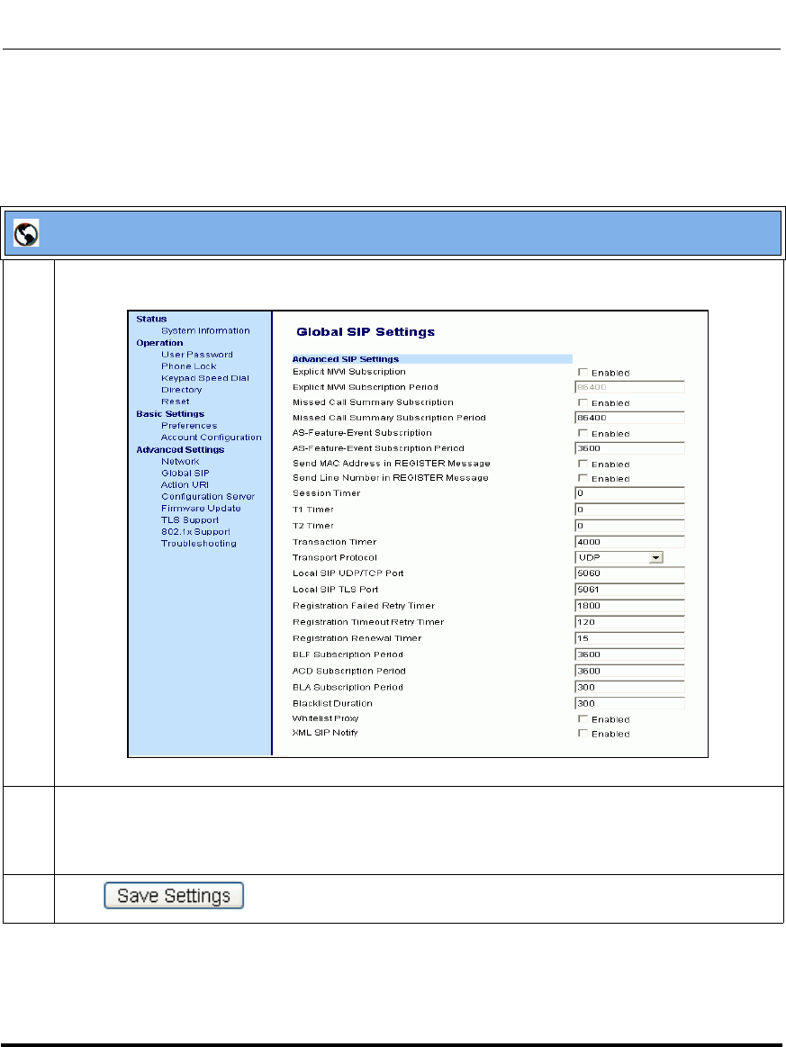
Advanced Operational Features
41-001160-03, Rev 00, Releaes 2.4 6-25
Configuring Advanced Operational Features
Configuring Whitelist Proxy Using the Aastra Web UI
Use the following procedure to configure the Whitelist Proxy feature using the
Aastra Web UI.
Aastra Web UI
1 Click on Advanced Settings->Global SIP->Advanced SIP Settings
2The "Whitelist Proxy" field is disabled by default. To enable this field, check the box.
When this feature is enabled, an IP phone accepts call requests from a trusted proxy server only. The
IP phone rejects any call requests from an untrusted proxy server.
3 Click to save your changes.
Draft 1

Advanced Operational Features
6-26 41-001160-03, Rev 00, Releaes 2.4
IP Phone Administrator Guide
Transport Layer Security (TLS)
The IP Phones support a transport protocol called Transport Layer Security
(TLS) and Persistent TLS. TLS is a protocol that ensures communication
privacy between the SIP phones and the Internet. TLS ensures that no third party
may eavesdrop or tamper with any message.
TLS is composed of two layers: the TLS Record Protocol and the TLS handshake
protocol. The TLS Record Protocol provides connection security with some
encryption method such as the Data Encryption Standard (DES). The TLS
Handshake Protocol allows the server and client to authenticate each other and to
negotiate an encryption algorithm and cryptographic keys before data is
exchanged. TLS requires the use of the following security certificate files to
perform TLS handshake:
• Root and Intermediate Certificates
• Local Certificate
•Private Key
• Trusted Certificate
When the phones use TLS to authenticate with the server, each individual call
must setup a new TLS connection. This can take more time when placing each
call. Thus, the IP phones also have a feature that allows you to setup the
connection to the server once and re-use that one connection for all calls from the
phone. It is called Persistent TLS. The setup connection for Persistent TLS is
established during the registration of the phone. If the phones are set to use
Persistent TLS, and a call is made from the phone, this call and all subsequent
calls use the same authenticated connection. This significantly reduces the delay
time when placing a call.
Draft 1
Advanced Operational Features
41-001160-03, Rev 00, Releaes 2.4 6-27
Configuring Advanced Operational Features
On the IP phones, an Administrator can configure TLS and Persistent TLS on a
global-basis only, using the configuration files or the Aastra Web UI.
SIP Asserted Identity (for Sylantro Servers)
The IP Phones support a private extension to the SIP, Asserted Identity (SAI)
within Trusted Networks (as defined in RFC 3325), inside the User Agent Server
(UA) in the Aastra IP phones.
This feature allows a network of trusted SIP servers to assert the identity of
authenticated users, and verify that phone messages originate from a Trusted
Identity. Upon receiving a message from a caller in the Trust Network, the IP
phone reads the contents of the P-Asserted-Identity (PAI) header field and
displays it on the phone UI. This field contains a more accurate description of the
caller identity (extension/phone number) than is contained in the SIP message.
Notes:
1. Persistent TLS requires the outbound proxy server and outbound
proxy port parameters be configured in either the configuration files or
the Aastra Web UI (Advanced Settings->Global SIP->Basic SIP Network
Settings). There can be only one persistent TLS connection created per
phone. The phone establishes the TLS connection to the configured
outbound proxy.
2. If you configure the phone to use Persistent TLS, you must also
specify the Trusted Certificate file to use. The Root and Intermediate
Certificates, Local Certificate, and Private Key files are optional.
Note: The phones support PAI header in the UPDATE message,
according to draft-ietf-sipping-update-pai-00. This feature is always
enabled.
If an UPDATE is received with a PAI header from a trusted source, the
phone updates the display with this information. The phone ignores any
PAI received from untrusted entities
Draft 1
Advanced Operational Features
6-28 41-001160-03, Rev 00, Releaes 2.4
IP Phone Administrator Guide
When an IP phone receives an incoming call, the IP phone does the following
actions:
• Checks to see if the incoming call is from a registered proxy server.
• If the call is forwarded via a registered proxy server, then the message has
already been verified and authenticated by the server. The caller is part of the
Trust Network. The IP phone UI displays the caller information contained in
the PAI header.
• If the call is not forwarded via a registered proxy server - and therefore is not
a “Trusted Entity” - the IP phone UI does not display any trust information
contained in the PAI header.
Configuring TLS Using the Configuration Files
You use the following parameters to configure TLS in the configuration files:
• sip transport protocol
• sips persistent tls
• sips root and intermediate certificates
• sips local certificate
• sips private key
• sips trusted certificates
Configuration Files
For the specific parameters you can set in the configuration files for setting TLS, see Appendix A, the
section, “Transport Layer Security (TLS) Settings” on page A-105.
Draft 1
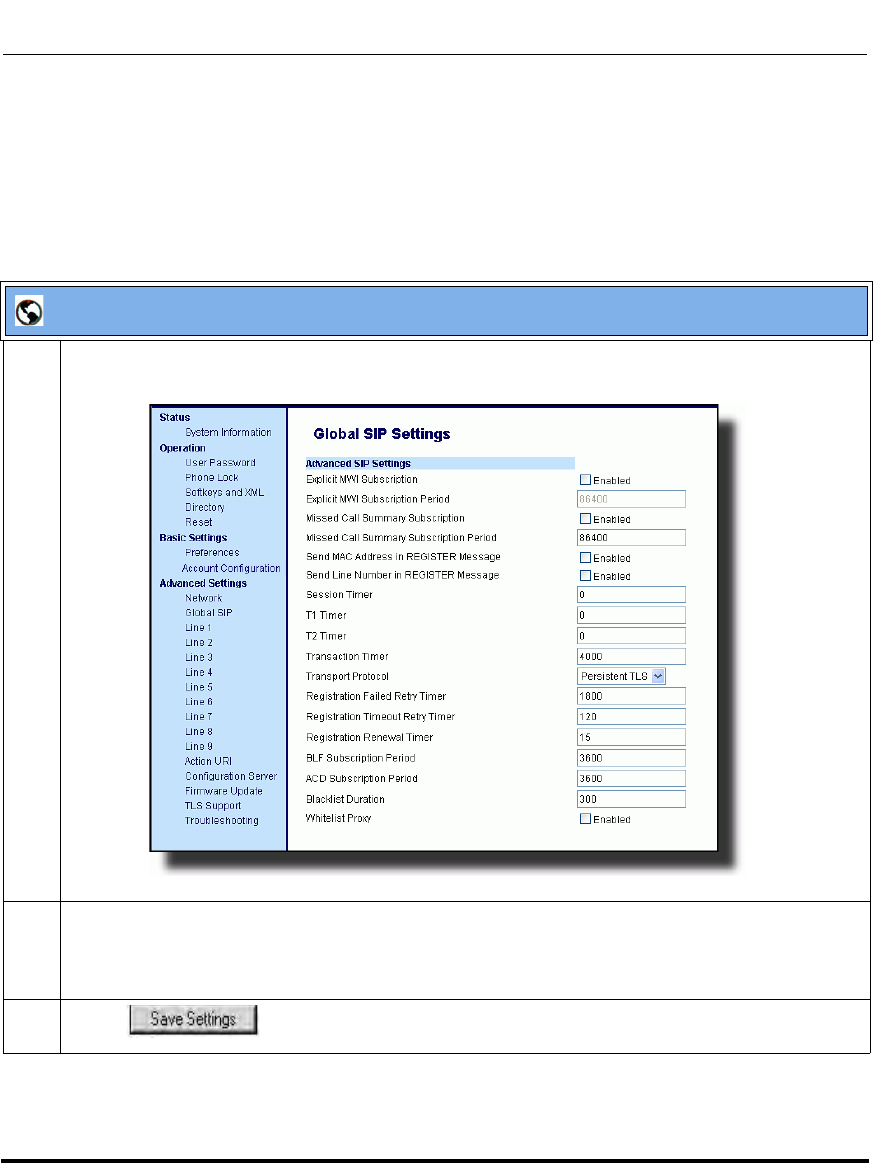
Advanced Operational Features
41-001160-03, Rev 00, Releaes 2.4 6-29
Configuring Advanced Operational Features
Configuring TLS Using the Aastra Web UI
To configure TLS using the Aastra Web UI, you must enable TLS or Persistent
TLS first. Then you must define the TLS certificate file names that you want the
phone to use. Use the following procedure to configure TLS using the Aastra Web
UI.
Aastra Web UI
1 Click on Advanced Settings->Global SIP->Advanced SIP Settings.
2 In the "Transport Protocol" field, select TLS or Persistent TLS.
Note: If configuring Persistent TLS, you must go to Advanced Settings->Global SIP->Basic Network
Settings and configure the “Outbound Proxy Server” and “Outbound Proxy Port” parameters.
3 Click to save your changes.
Draft 1
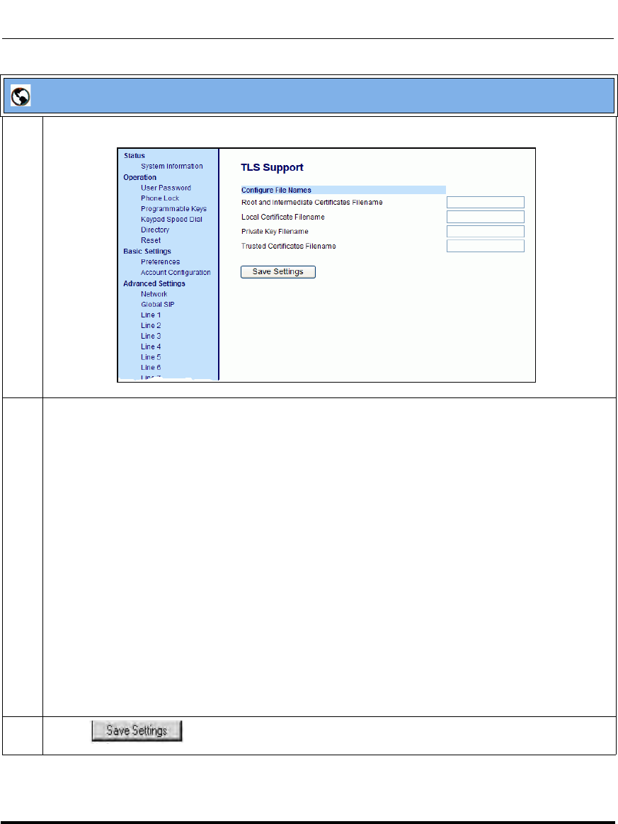
Advanced Operational Features
6-30 41-001160-03, Rev 00, Releaes 2.4
IP Phone Administrator Guide
4 Click on Advanced Settings->TLS Support.
5 Enter the certificate file names and the private key file name in the appropriate fields.
The Root and Intermediate Certificate files contain one root certificate and zero or more intermediate
certificates which must be placed in order of certificate signing with root certificate being the first in
the file. If the local certificate is signed by some well known certificate authority, then that authority
provides the user with the Root and Intermediate Certificate files (most likely just CA root certificate).
The Trusted Certificate files define a list of trusted certificates. The phone’s trusted list must contain
the CA root certificates for all the servers it is connecting to. For example, if the phone is connecting
to server A which has a certificate signed by CA1, and server B which has a certificate signed by
CA2, the phone must have CA1 root certificate and CS2 root certificate in its Trusted Certificate file.
Notes:
1. If configuring TLS, you must specify the files for Root and Intermediate Certificates, the Local
Certificate, the Private Key, and the Trusted Certificates in order for the phone to receive calls.
2. If configuring Persistent TLS, you must specify the Trusted Certificates (which contains the trusted
certificate list). All other certificates and the Private Key are optional.
3. The certificate files and Private Key file names must use the format “.pem”.
4. To create custom certificate files and private key files to use on your IP phone, contact Aastra
Technical Support.
6 Click to save your changes.
Aastra Web UI
Draft 1

Advanced Operational Features
41-001160-03, Rev 00, Releaes 2.4 6-31
Configuring Advanced Operational Features
802.1x Support
The IP phones support the IEEE 802.1x protocol. The 802.1x protocol is a
standard for passing Extensible Authentication Protocol (EAP) over a wired or
wireless Local Area Network (LAN).
The 802.1x protocol on the IP phone facilitates media-level access control, and
offers the capability to permit or deny network connectivity, control LAN access,
and apply traffic policy, based on user or endpoint identity. This feature supports
both the EAP-MD5 and EAP-TLS protocols.
If 802.1x on the phone is enabled, the following screen displays during startup of
the phone.
If the 802.1x failed to authenticate with the server, the phone continues it's normal
startup process using DHCP. However, the network port on the phone may or may
not be disabled, depending on the switch configuration.
Certificates and Private Key Information
• If the certificates and private key are NOT stored in the phone:
— the phone connects to an open unauthenticated VLAN and the certificates
are downloaded.
or
— the phone connects using EAP-MD5 to a restricted VLAN and the
certificates are downloaded.
>> 10%
802.1x Authenticating....
Draft 1
Advanced Operational Features
6-32 41-001160-03, Rev 00, Releaes 2.4
IP Phone Administrator Guide
• If the certificates and private key ARE stored in the phone, the phone uses
them during the authentication process.
• If the phone uses EAP-TLS for successful authentication, after the phone
reboots, it downloads the latest certificates and private key files to the phone.
• The private key uses AES-128 to encrypt the private key file.
• Switch Supplicant Mode - The switch supports the following 2 modes:
—Single supplicant - This mode enables the port once any machine
connected to this port is authenticated. For security reasons, the IP phone
has the option to disable the pass-through port.
—Multiple supplicants - Using this mode, the switch can support multiple
clients connected to same port. The switch distinguishes between the
clients based on their MAC address.
• Factory default and recovery mode deletes all certificates and private keys,
and sets the EAP type to disabled.
You can configure the 802.1x feature on the IP phone using the configuration
files, the IP Phone UI, or the Aastra Web UI.
Note: If configuring 802.1x using the IP Phone UI, the certificates
and private keys must already be configured and stored on the phone.
Use the configuration files or the Aastra Web UI to load certificates
and private keys.
Draft 1

Advanced Operational Features
41-001160-03, Rev 00, Releaes 2.4 6-33
Configuring Advanced Operational Features
Configuring the 802.1x Protocol Using the Configuration Files
You use the following parameters to configure the 802.1x Protocol on your phone
using the configuration files.
For EAP-MD5 use:
• eap type
•identity
• md5 password
• pc port passthrough enabled
For EAP-TLS use:
• eap type
•identity
• 802.1x root and intermediate certificates
(use 1 root and 0 or 1 intermediate certificates)
• 802.1x local certificate
(use 1 local certificate)
• 802.1x private key
(1 private key that corresponds to local certificate)
• 802.1x trusted certificates
(0 or more trusted certificates (a maximum of 2))
• pc port passthrough enabled
Configuration Files
For the specific parameters you can set in the configuration files for setting 802.1x support, see Appendix A,
the section, “802.1x Support Settings” on page A-109.
Draft 1
Advanced Operational Features
6-34 41-001160-03, Rev 00, Releaes 2.4
IP Phone Administrator Guide
Configuring the 802.1x Protocol Using the IP Phone UI
Use the following procedure to configure the 802.1x Protocol on your phone
using the IP Phone UI.
Note: If configuring 802.1x using the IP Phone UI, the
certificates and private keys must already be configured and
stored on the phone. Use the configuration files or the Aastra
Web UI to load certificates and private keys.
Aastra IP Phone UI
Step Action
1 Press to enter the Options List.
2Select Administrator Menu and enter your Administrator password.
Draft 1
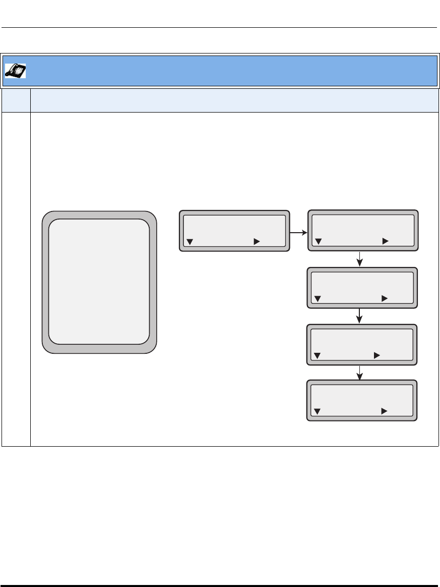
Advanced Operational Features
41-001160-03, Rev 00, Releaes 2.4 6-35
Configuring Advanced Operational Features
3On 9480i, 9480i CT, 6755i, 6757i, and 6757i CT:
Select Network Settings->Ethernet->Enable PassThru Port.
On the 9143i, 6751i, 6753i:
Select Network Settings->Ethernet->PC Port Enabled.
Aastra IP Phone UI
Step Action
Done -
Ethernet Link
1. LAN Port Link
2. PC Port Link
3. Enable PassThru Port
4. 802.1x Settings
- Select
9480i, 9480i CT,
10. Ethernet
Next Enter
1. LAN Port Link
Next Enter
2. PC Port Link
Next Enter
4. 802.1x Settings
Next Enter
3. PC Port Enabled
Yes
Next Change
9143i, 6751i, 6753i
6755i, 6757i, 6757i CT
Draft 1
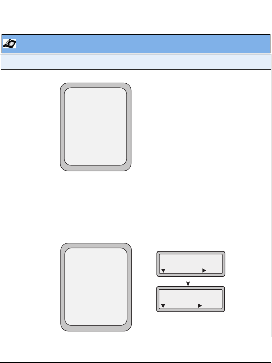
Advanced Operational Features
6-36 41-001160-03, Rev 00, Releaes 2.4
IP Phone Administrator Guide
4 The PC PassThru Port is enabled by default.
Note: The PC PassThru Port must be enabled to use the 802.1x Protocol.
5 Press Done (on 9480i, 9480i CT, 6755i, 6757i, 6757i CT).
or
Press Next (on 9143i, 6751i, 6753i).
6Select 802.1x Settings.
7Select 802.1x Mode.
Aastra IP Phone UI
Step Action
Done -
Enable PassThru Port
Enable PassThru Port
Yes
Cancel -
- Change
Done -
802.1x Settings
1. 802.1x Mode
2. EAP-MD5 Settings
- Select
2. EAP-MD5 Settings
Yes
Next Enter
1. 802.1x Mode
Next Enter
Draft 1
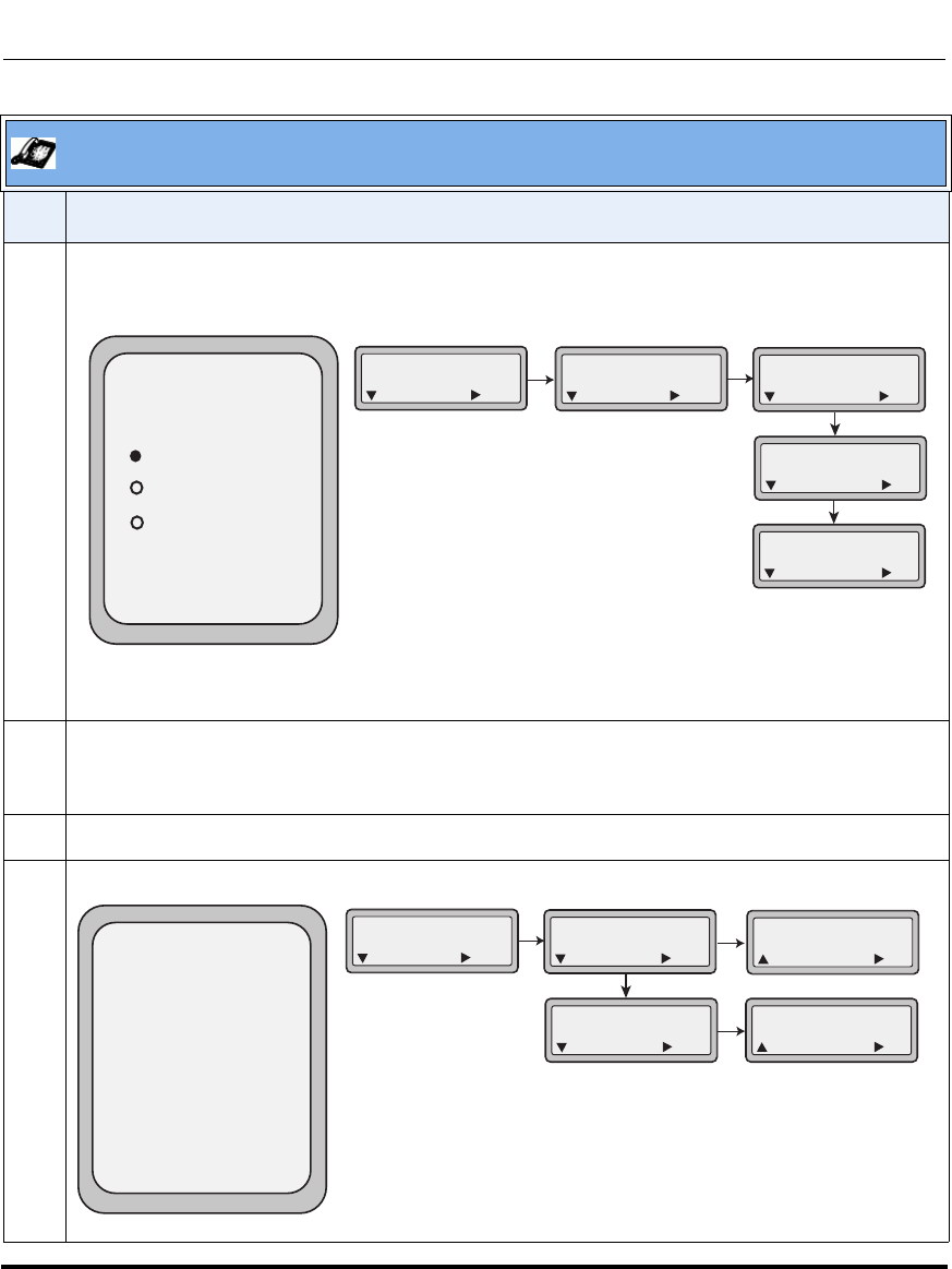
Advanced Operational Features
41-001160-03, Rev 00, Releaes 2.4 6-37
Configuring Advanced Operational Features
8Select EAP-MD5 to configure the phone to use MD5 authentication;
or
Select EAP-TLS to configure the phone to use TLS authentication.
Note: The 802.1x Protocol is disabled by default. If you select EAP-TLS authentication, you must use
the configuration files or the Aastra Web UI to configure the certificates and private key for the phone.
9 Press Done (on 9480i, 9480i CT, 6755i, 6757i, 6757i CT)
or
Press Set (on 9143i, 6751i, 6753i).
10 To configure MD5, select EAP-MD5 Settings.
11 Select Identity.
Aastra IP Phone UI
Step Action
Done -
802.1x Mode
Disabled
Cancel -
EAP-MD5
EAP-TLS
1. 802.1x Mode
Next Enter
802.1x Mode
Disabled
Next Set
4. 802.1x Settings
Next Enter
802.1x Mode
EAP-MD5
Next Set
802.1x Mode
EAP-TLS
Next Set
Done -
EAP-MD5 Setting
1. Identity
2. MD5 Password
- Select
1. EAP-MD5 Settings
Next Enter
1. Identity
Next Enter
2. MD5 Password
Next Enter
User Name
|
Cancel Set
Password
|
Cancel Set
Draft 1
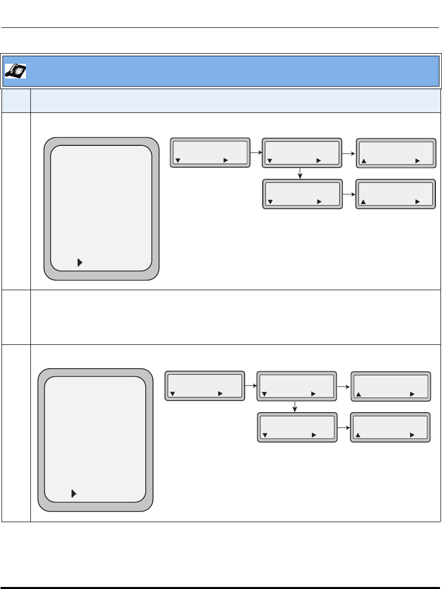
Advanced Operational Features
6-38 41-001160-03, Rev 00, Releaes 2.4
IP Phone Administrator Guide
12 Enter the identity or username used for authenticating the phone.
13 Use the keys as applicable while entering the username; then press Done (9480i, 9480i CT, 6755i,
6757i, 6757i CT).
or
Press Set (9143i, 6751i, 6753i).
14 Enter the password used for authenticating the phone.
Aastra IP Phone UI
Step Action
Done -
Username
Username:
|
- Backspace
- ABC
Cancel -
Nextspace -
1. EAP-MD5 Settings
Next Enter
1. Identity
Next Enter
2. MD5 Password
Next Enter
User Name
|
Cancel Set
Password
|
Cancel Set
Done -
Password
Password:
|
- Backspace
- ABC
Cancel -
Nextspace -
1. EAP-MD5 Settings
Next Enter
1. Identity
Next Enter
2. MD5 Password
Next Enter
User Name
|
Cancel Set
Password
|
Cancel Set
Draft 1
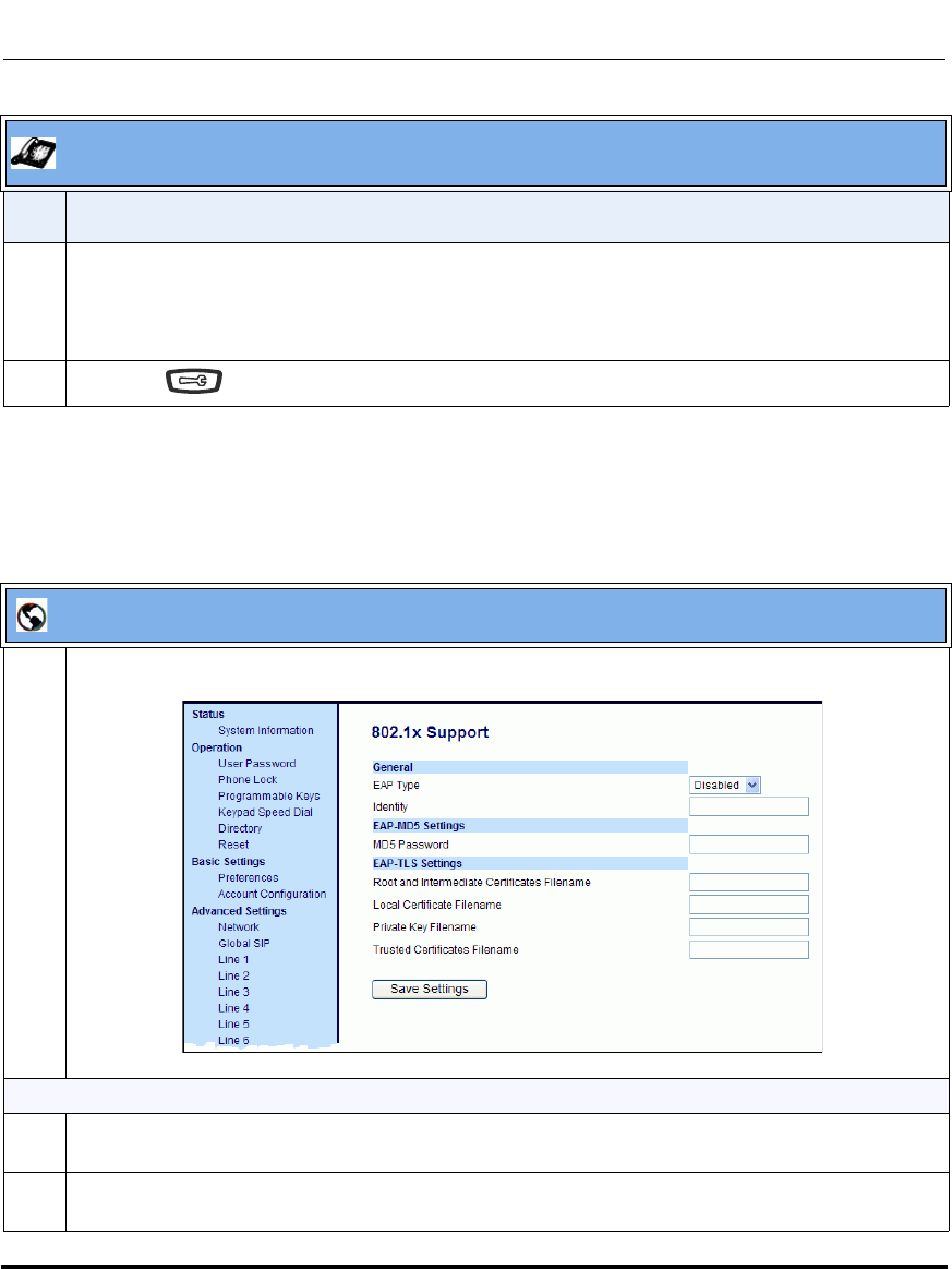
Advanced Operational Features
41-001160-03, Rev 00, Releaes 2.4 6-39
Configuring Advanced Operational Features
Configuring the 802.1x Protocol Using the Aastra Web UI
Use the following procedure to configure the 802.1x Protocol on your phone
using the Aastra Web UI.
15 Use the keys as applicable while entering the password; then press Done (9480i, 9480i CT, 6755i,
6757i, 6757i CT).
or
Press Set (9143i, 6751i, 6753i).
16 Press the key to save your settings and exit from the IP Phone UI.
Aastra Web UI
1 Click on Advanced Settings->802.1x Support.
To configure EAP-MD5:
2 In the “EAP Type” field, select EAP-MD5.
Valid values are: Disabled (Default), EAP-MD5, and EAP-TLS.
3 In the “Identify” field, enter an Identity for the IP phone for which you are configuring 802.1x.
For example, phone1.
Aastra IP Phone UI
Step Action
Draft 1

Advanced Operational Features
6-40 41-001160-03, Rev 00, Releaes 2.4
IP Phone Administrator Guide
4 In the “MD5 Password” field, enter a password used for the MD5 authentication of the phone.
For example, password1.
5 Click to save your changes.
6 Click on Advanced Settings->Network->Basic Network Settings.
7The “PC Port PassThru Enable/Disable” field is enabled by default. To disable this field, uncheck
the box.
Note: The PC Port PassThru Enable Disable field must be enabled to use the 802.1x Protocol.
8 Click to save your changes.
Aastra Web UI
PC Port PassThru
Enable/Disable
Draft 1
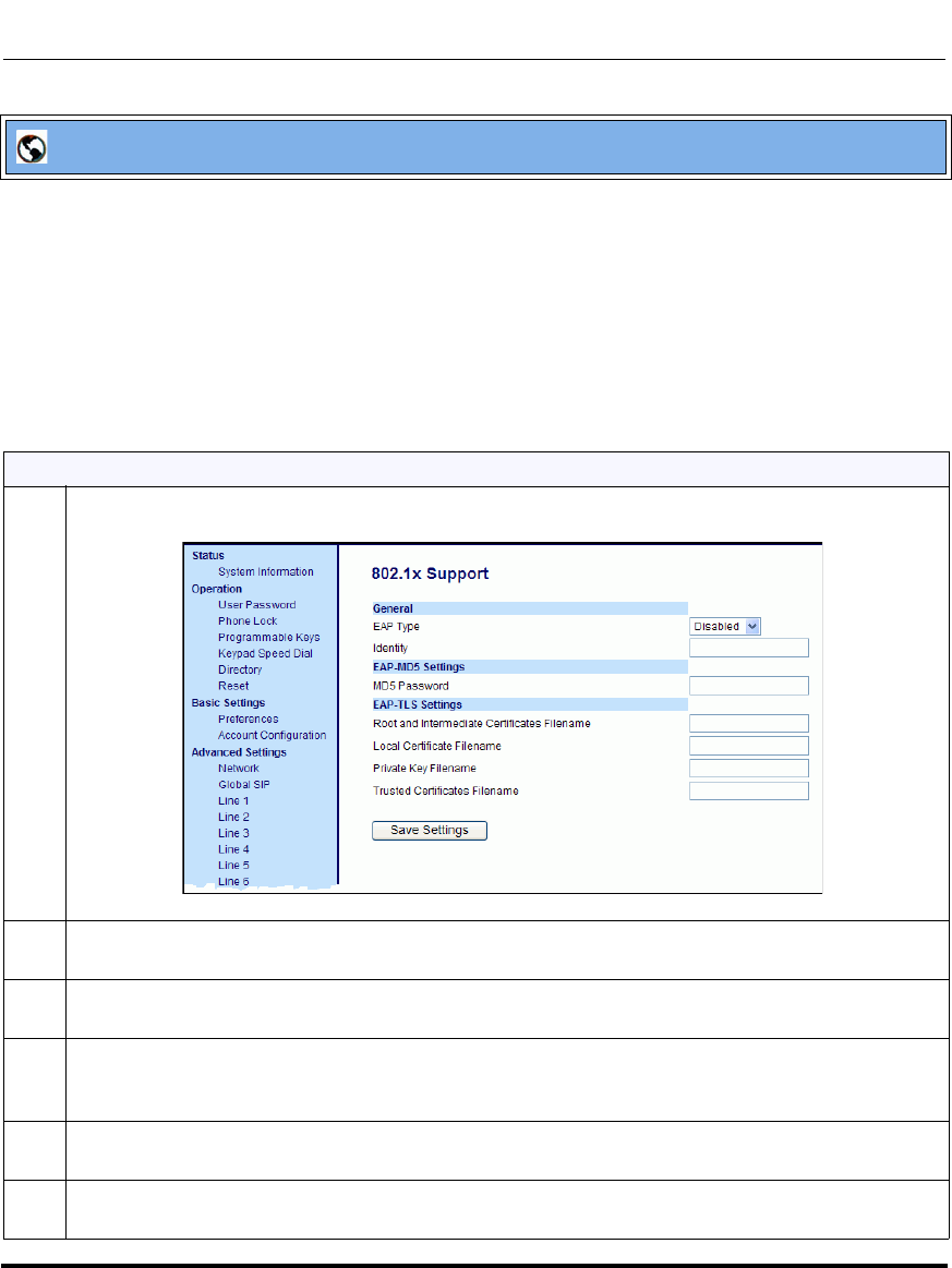
Advanced Operational Features
41-001160-03, Rev 00, Releaes 2.4 6-41
Configuring Advanced Operational Features
To configure EAP-TLS:
1 Click on Advanced Settings->802.1x Support.
1 In the “EAP Type” field, select EAP-TLS.
Valid values are: Disabled (Default), EAP-MD5, and EAP-TLS.
2 In the “Identity” field, enter an Identity for the IP phone for which you are configuring 802.1x.
For example, phone1.
3 In the “Root and Intermediate Certificates Filename” field, enter the filename that contains the root
and intermediate certificates related to the local certificate. For example:
root_Intermed_certifi.pem.
4 In the “Local Certificate Filename” field, enter the filename that contains the local certificate. For
example: localcertificate.pem.
5 In the “Private Key Filename” field, enter the filename that contains the private key. For example:
privatekey.pem.
Aastra Web UI
Draft 1
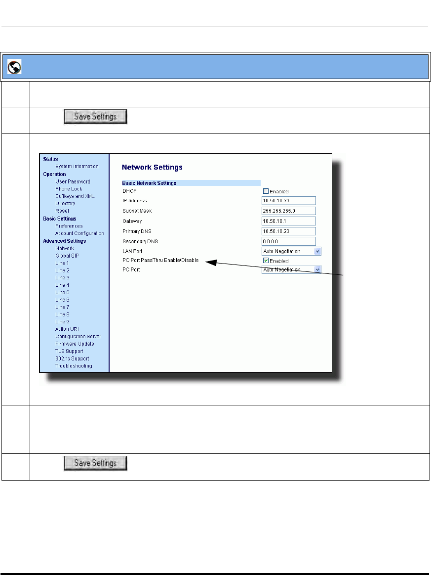
Advanced Operational Features
6-42 41-001160-03, Rev 00, Releaes 2.4
IP Phone Administrator Guide
6In the “Trusted Certificates Filename” field, enter the filename that contains the trusted certificates.
For example: trusted_certificates.pem.
7 Click to save your changes.
8 Click on Advanced Settings->Network->Basic Network Settings.
9The “PC Port PassThru Enable/Disable” field is enabled by default. To disable this field, uncheck
the box.
Note: The PC Port PassThru Enable Disable field must be enabled to use the 802.1x Protocol.
10 Click to save your changes.
Aastra Web UI
PC Port PassThru
Enable/Disable
Draft 1

Advanced Operational Features
41-001160-03, Rev 00, Releaes 2.4 6-43
Configuring Advanced Operational Features
Symmetric UDP Signaling
By default, the IP phones use symmetric UDP signaling for outgoing UDP SIP
messages. When symmetric UDP is enabled, the IP phone generates and listens
for UDP messages using port 5060.
You can manually disable symmetric UDP signaling using the IP phone’s
configuration file. When you disable symmetric UDP signaling, then the IP phone
chooses a random source port for UDP messages.
The IP phone also chooses a random source port for UDP messages if you
configure a backup proxy server, registrar server, or outbound proxy server.
An Administrator can configure symmetric UDP signaling using the configuration
files only.
Configuring Symmetric UDP Signaling Using the Configuration Files
You use the following parameter to enable or disable Symmetric UDP Signaling
in the configuration files:
• sip symmetric udp signaling
Configuration Files
For the specific parameter you can set in the configuration files, see Appendix A, the section, “RTP, Codec,
DTMF Global Settings” on page A-114.
Draft 1
Advanced Operational Features
6-44 41-001160-03, Rev 00, Releaes 2.4
IP Phone Administrator Guide
Removing UserAgent and Server SIP Headers
Currently, the phone always configures the SIP UserAgent/Server headers to
contain:
Aastra <PhoneModel>/<FirmwareVersion>
You can suppress the addition of these headers by using the following parameter
in the configuration files:
• sip user-agent
Setting this parameter allows you to enable or disable the addition of the
User-Agent and Server SIP headers from the SIP stack.
You can configure this feature using the configuration files only.
Configuring UserAgent/Server SIP Headers
You use the following parameter to specify whether the UserAgent and Server SIP
header is added to the SIP stack.
• sip user-agent
Configuration Files
For the specific parameter you can set in the configuration files, see Appendix A, the section, “User-Agent
Setting” on page A-241.
Draft 1

Advanced Operational Features
41-001160-03, Rev 00, Releaes 2.4 6-45
Configuring Advanced Operational Features
GRUU and sip.instance Support
Globally Routable User-Agent URIs (GRUUs) provide a way for anyone on the
Internet to route a call to a specific instance of a User-Agent.
The IP phones provide GRUU support using draft-ietf-sip-gruu-15. A sip.instance
is added to all non-GRUU contacts. By default, this feature is enabled. You can
enable or disable this support using the configuration files.
Limitations of the GRUU Feature
The following are limitations of the GRUU feature on the phones:
• GRUU-Draft-15 is not compatible with versions prior to GRUU-Draft-10.
• Phones do not support temporary or phone-created GRUUs.
Enabling/Disabling GRUU and sip.instance Support
Use the following procedure to enable/disable GRUU and sip.instance support.
Configuration Files
For the specific parameter you can set in the configuration files, see Appendix A, the section, “GRUU and
sip.instance Support” on page A-241.
Draft 1

Advanced Operational Features
6-46 41-001160-03, Rev 00, Releaes 2.4
IP Phone Administrator Guide
Multi-Stage Digit Collection (Billing Codes) Support (for Sylantro
Servers)
The IP Phones support Multi-Stage Digit Collection (billing codes) for Sylantro
Servers. Sylantro Server features, like mandatory and optional billing codes,
requires that the application server notify the phone to collect more digits before
completing the call. The IP phone is able to collect digits in two stages to support
the billing code feature.
Aastra IP Phone users are prompted to enter the correct billing code when they
dial these numbers:
• External numbers.
• Eternal numbers dialed using a Speeddial key.
Billing Codes Implementation Notes
Note the following implementation information:
• IP phone users may enter a 2-9 digit billing code. Billing codes may not start
with either 0 (Operator) or 9 (external calls).
• When using Sylantro Click-to-Call, IP phone users select a billing code from
a pull-down menu.
• When placing a call, a secondary dial tone alerts IP phone users to enter the
billing code. The IP phone UI also displays a “Enter Billing Code” message.
• If an IP phone user redials a number, they do not have to re-enter the billing
code. The billing code information is maintained and processed accordingly.
• If an IP phone user enters an invalid billing code, the call fails.
Mandatory versus Optional Billing Codes
This release of the Aastra IP phones supports two types of billing codes:
Mandatory and Optional. The Sylantro server configuration determines which
type of billing code is used on the IP phones.
•Mandatory billing codes: Calls are not connected until the user enters a valid
billing code. The user dials the phone number. When prompted for billing
codes, user dials the billing code.
Draft 1

Advanced Operational Features
41-001160-03, Rev 00, Releaes 2.4 6-47
Configuring Advanced Operational Features
For example, suppose the IP phone user is using billing code 300, and dialing
the external number 617-238-5500. The IP user then enters the number using
the following format:
6172385000#300
Using mandatory billing codes, if the user is configuring a Speeddial number,
then they enter the number using the following format:
<phonenumber>%23<billingcode>
To use this format with the default dial plan terminator (#), the # sign required
by Sylantro as a delimiter should be represented as an escaped character by
using the sequence %23. The speed dial format for an external number that
includes a mandatory billing code becomes:
<phonenumber>%23<billing code>
•Optional billing codes: The user dials an optional billing code by dialing
*50, followed by the billing code digits. When prompted for additional digits,
user enters the phone number.
For example, suppose the IP phone user is using billing code 500, and dialing
the external number 617-238-5000. The IP user then enters the number using
the following format:
*50500#6172385000
If the user is dialing configuring a Speeddial number, then they enter the
number using the following format:
*50<billingcode>#<phonenumber>
To use this format with the default dial plan terminator (#), the # sign
required by Sylantro as a delimiter should be represented as an escaped
character by using the sequence %23. The speed dial format for an
external number that includes an optional billing code becomes:
*50<billing code>%23<phone number>
Draft 1

Advanced Operational Features
6-48 41-001160-03, Rev 00, Releaes 2.4
IP Phone Administrator Guide
Numbers Not Requiring Billing Codes
Billing codes are not required for the following two types of calls:
• Emergency calls (E911)
• Calls between extensions
Draft 1

Advanced Operational Features
41-001160-03, Rev 00, Releaes 2.4 6-49
Configuring Advanced Operational Features
Configurable DNS Queries
The domain name system (DNS) is the way that Internet domain names are
located and translated into Internet Protocol addresses. A domain name is a
meaningful and easy-to-remember identifier for an Internet address.
The lists of domain names and IP addresses are distributed throughout the Internet
in a hierarchy of authority within a database of records. There is usually a DNS
server within close proximity to your geographic location that maps the domain
names in your Internet requests or forwards them to other servers in the Internet.
The IP Phones support three methods of DNS lookups allowing it to adapt to
various deployment environments: eNone, eSRV, and eNAPTR&SRV. (See the
following table for a description of each method). When the IP Phone accesses the
Internet, it sends out a DNS query to the proxy to lookup the IP address and the
port, and then waits for a response from the proxy.
You can configure the phone to use any one of these methods by entering the
applicable value in the configuration files:.
Configuration
File Value DNS Server
Method Used Description
0 A only The phone sends “A” (Host IP Address) lookup for the IP address
and uses the default port number of 5060.
1SRV & AThe phone sends “SRV” (Service Location Record) lookup to get
the port number. Most often, the IP address is included in the
response from the DNS server to avoid extra queries. If there is no
IP address returned in the response, the phone sends out the “A”
DNS lookup to find the IP address.
2 NAPTR & SRV & A First, the phone sends "NAPTR" (Naming Authority Pointer) lookup
to get the “SRV” pointer and service type (such as "aastra.com
SIP+2DT .... _sip.tcp.aastra.net", which means the service prefers
to use TCP and "_sip.tcp.aastra.net" for the SRV query instead of
the default "_sip._tcp.aastra.com"). If the NAPTR record is
returned empty then the default value is used, so in the same case,
the phone will use "_sip._udp.aastra.com" for the next step lookup.
Next, the phone does SRV lookup to get the IP address and port
number. If there is no IP address in the SRV response then it
sends out and “A” lookup to get it.
Draft 1
Advanced Operational Features
6-50 41-001160-03, Rev 00, Releaes 2.4
IP Phone Administrator Guide
Configuring the DNS Query Method
You can configure the DNS query method for the phone to use for performing
DNS lookups using the following parameter in the configuration files:
• sip dns query type
Note: On the phone side, if you configure the phone with a Fully-
Qualified Domain Name (FQDN) proxy and specified port, the phone
always sends “A only” lookups to find the Host IP Address of the proxy.
Configuration Files
For the specific parameter you can set in the configuration files, see Appendix A, the section, “DNS Query
Setting” on page A-242.
Draft 1
Advanced Operational Features
41-001160-03, Rev 00, Releaes 2.4 6-51
Configuring Advanced Operational Features
Ignore Out of Sequence Errors
An Administrator can configure the phone via the “sip accept out of order
requests” parameter to ignore CSeq number errors on all SIP dialogs on the
phone. When this parameter is enabled, the phone no longer verifies that the
sequence numbers increase for each message within a dialog, and does not report
a "CSeq Out of Order" error if they do not increase.
An Administrator can enable/disable this feature using the configuration files
only.
Enabling/Disabling “Out of Order SIP Requests”
Use the following procedure to enable/disable “out of order SIP requests”.
Note: As the default Asterisk configuration does not fully track dialogs
through a reboot, it is recommended that this parameter be enabled when
using the BLF feature with an Asterisk server. If you do not enable this
feature, then rebooting the Asterisk server may cause BLF to stop
working. With this parameter enabled, the BLF key starts working again
when the phone re-subscribes, which by default, are one hour apart.
Configuration Files
For the specific parameter you can set in the configuration files, see Appendix A, the section, “Ignore Out of
Order SIP Requests” on page A-243.
Draft 1

Advanced Operational Features
6-52 41-001160-03, Rev 00, Releaes 2.4
IP Phone Administrator Guide
“Early-Only” Parameter in Replaces Header RFC3891
The phones support the “early-only” parameter in the “Replaces” header
according to RFC3891. When the phone receives a Replaces header with the
early-only parameter, it replaces the existing dialog if the call is still in the early
state. If the call has been answered, then the Replaces request is rejected.
Reason Header Field in SIP Message
The IP Phones support the receiving of the Reason Header Field in a SIP
CANCEL message, as described in RFC3326. This allows a call that is answered
from somewhere else to still display in the Callers List. Also, the missed calls
indicator and counter do not change.
Limitation
If the call is answered somewhere else, the duration of the call does not display in
the Callers List.
Note: This feature is not supported in outgoing requests.
Draft 1

41-001160-03, Rev 00, Releaes 2.4 7-1
Chapter 7
Encrypted Files on the IP Phone
About this chapter
Introduction
This chapter provides information about encryption on the IP phones and provides
methods an administrator can use to store encrypted files to a server.
Topics
This chapter covers the following topics:
Topic Page
Encrypted Files on the IP Phone page 7-2
Configuration File Encryption Method page 7-2
Procedure to Encrypt Configuration Files page 7-4
Vendor Configuration File Encryption page 7-6
Draft 1
Encrypted Files on the IP Phone
7-2 41-001160-03, Rev 00, Releaes 2.4
IP Phone Administrator Guide
Encrypted Files on the IP Phone
An encryption feature for the IP phone allows Service Providers the capability of
storing encrypted files on their server to protect against unauthorized access and
tampering of sensitive information (i.e., user accounts, login passwords,
registration information). Service Providers also have the capability of locking a
phone to use a specific server-provided configuration only.
Configuration File Encryption Method
Only a System Administrator can encrypt the configurations files for an IP Phone.
System Administrators use a password distribution scheme to manually
pre-configure or automatically configure the phones to use the encrypted
configuration with a unique key.
From a Microsoft Windows command line, the System Administrator uses an
Aastra-supplied encryption tool called "anacrypt.exe" to encrypt the <MAC>.tuz
file.
This tool processes the plain text <mac>.cfg and aastra.cfg files and creates
triple-DES encrypted versions called <mac>.tuz and aastra.tuz. Encryption is
performed using a secret password that is chosen by the administrator.
The encryption tool is also used to create an additional encrypted tag file called
security.tuz, which controls the decryption process on the IP phones. If
security.tuz is present on the TFTP/FTP/HTTP server, the IP phones download it
and use it locally to decrypt the configuration information from the aastra.tuz and
<mac>.tuz files. Because only the encrypted versions of the configuration files
need to be stored on the server, no plain-text configuration or passwords are sent
across the network, thereby ensuring security of the configuration data.
Note: Aastra also supplies encryption tools to support Linux platforms
(anacrypt.linux) and Solaris platforms (anacrypt.sunos) if required.
Draft 1

Encrypted Files on the IP Phone
41-001160-03, Rev 00, Releaes 2.4 7-3
Encrypted Files on the IP Phone
To make changes to the configuration files, the System Administrator must save
the original files.
The security feature described above prevents unauthorized parties from reading
or writing the contents of the <MAC>.tuz file. It also provides the following:
• Prevents users from using the <MAC>.tuz file that does not match the user’s
phone MAC address.
• Renders the <MAC>.tuz file invalid if the user renames the file.
• Works with IP phone releases prior to Release 2.2.
• Provides compatibility between the previous encryption routine and the new
decryption routine.
Note: If the use of encrypted configuration files is enabled (via
security.tuz or pre-provisioned on the IP phone) the aastra.cfg and
<mac>.cfg files are ignored, and only the encrypted equivalent files
aastra.tuz and <mac>.tuz are read.
Draft 1

Encrypted Files on the IP Phone
7-4 41-001160-03, Rev 00, Releaes 2.4
IP Phone Administrator Guide
Procedure to Encrypt Configuration Files
To encrypt the IP phone configuration files:
1. Open a command line window application (i.e., DOS window).
2. At the prompt, enter anacrypt.exe and press <Return>.
C:\> anacrypt.exe -h
Provides encryption of the configuration files used for the family of Aastra IP
phones, using 56bit triple-DES and site-specific keys.
Copyright (c) 2008, Aastra Technologies, Ltd.
Copyright (c) 1999, Philip J. Erdelsky
Usage:
anacrypt {infile.cfg|-d <dir>} [-p password] [-m] [-i] [-v] [-h]
Note: Incorrect password produces garbage. For site-specific keyfile
security.cfg the plaintext must match password.
Anacrypt Switch Description
{infile.cfg | -d <dir>} Specifies that all .cfg files in <dir> should be encrypted
[-p password] Specifies password used to generate keys
-m Generate MAC.tuz files that are phone specific. This switch generates files that are
only usable for phones with firmware version 2.2.0 and above.
-i Generate security.tuz file
-v Specifies the version of encryption that the anacrypt tool uses. Use version 1 encryption
(i.e., -v1) to generate firmware that is readable by all model phones. Without the -v1
switch, the anacrypt tool generates files that are only readable by phones with
firmware 2.2.0 and above.
-h Display program help text
Draft 1

Encrypted Files on the IP Phone
41-001160-03, Rev 00, Releaes 2.4 7-5
Encrypted Files on the IP Phone
Examples
The following examples illustrate the use of the anacrypt.exe file.
Example 1
Generating a security.tuz file with password 1234abcd
For firmware version 2.2.0 and up:
C:\>anacrypt -i -p 1234abcd
For any firmware version:
C:\>anacrypt -i -p 1234abcd -v1
Example 2
Encrypting a single aastra.cfg file with password 1234abcd
C:\>anacrypt aastra.cfg -p 1234abcd
Example 3
Encrypting a <mac>.cfg file with password 1234abcd
C:\>anacrypt 00085d000000.cfg -p 1234abcd
Example 4
Encrypting a <mac>.cfg file with password 1234abcd using the new MAC
encryption (-m is only supported for firmware version 2.2.0 and up)
C:\>anacrypt 00085d000000.cfg -m -p 1234abcd
Draft 1

Encrypted Files on the IP Phone
7-6 41-001160-03, Rev 00, Releaes 2.4
IP Phone Administrator Guide
Example 5
Encrypting all cfg files in C:\data with password 1234abcd using the new MAC
encryption and generating a security.tuz file at the same time.(2.2.0 and up)
C:\>anacrypt -d C:\data -p 1234abcd -m -i
Example 6
Encrypting all cfg files in C:\data with password 1234abcd using the and
generating a security.tuz file at the same time for all firmware versions.(any
version)
C:\>anacrypt -d C:\data -p 1234abcd -i -v1
Vendor Configuration File Encryption
Some vendors can have specific methods to encrypt files on their configuration
servers. For each phone, the configuration server can generate a random hex string
(encryption key) that is used to encrypt the phone’s MAC-specific configuration
file.
The encryption key is placed in a plain text MAC-specific configuration file that
the server downloads to the phone. After the phone receives the file, it updates the
encryption key.
This method of encryption does not affect the implementation of the Aastra
method of file encryption.
You can set the phone-specific encryption key using the configuration files only.
For more information about configuration file encryption, contact Aastra
Technical Support.
Note: The aastra.cfg file is not encrypted with this feature.
Draft 1

Encrypted Files on the IP Phone
41-001160-03, Rev 00, Releaes 2.4 7-7
Encrypted Files on the IP Phone
Configuring Vendor Configuration File Encryption
Use the following procedure to configure vendor configuration file encryption on
the IP Phones.
Configuration Files
For specific parameters you can set in the configuration files for automatic update, see Appendix A, the
section, “Configuration Encryption Setting” on page A-243.
Draft 1

Encrypted Files on the IP Phone
7-8 41-001160-03, Rev 00, Releaes 2.4
IP Phone Administrator Guide
Draft 1

About this chapter
41-001160-03, Rev 00, Releaes 2.4 8-1
Upgrading the Firmware
Chapter 8
Upgrading the Firmware
About this chapter
Introduction
This chapter provides information about upgrading the IP phone firmware.
Topics
This chapter covers the following topics:
Topic Page
Upgrading the Firmware page 8-2
Using the “Firmware Update” Page in the Aastra Web UI page 8-2
Using the Restart Feature page 8-5
Using the Auto-Resync Feature page 8-7
Draft 1

Upgrading the Firmware
8-2 41-001160-03, Rev 00, Releaes 2.4
IP Phone Administrator Guide
Upgrading the Firmware
The IP phones support the protocols, TFTP, FTP, HTTP or HTTPS to download
configuration files and upgrade firmware to the phones from a configuration
server.
The configuration server should be ready and able to accept connections. For
information on configuration server requirements, see Chapter 1, the section,
“Configuration Server Requirement” on page 1-35.
You can download the firmware stored on the configuration server in one of three
ways:
• Using the “Firmware Update” page in the Aastra Web UI at the location
Advanced Settings->Firmware Update.
• Using the IP Phone UI or the Aastra Web UI to restart the phone. The phone
automatically looks for firmware updates and configuration files during the
boot process.
• Setting an Auto-Resync feature to automatically update the firmware,
configuration files, or both at a specific time in a 24-hour period). (Feature
can be enabled using the configuration files or the Aastra Web UI).
Using the “Firmware Update” Page in the Aastra Web UI
You can use the Aastra Web UI to manually force a firmware update from the
configuration server to a phone in your network by selecting Advanced
Settings->Firmware Update. You can configure the phone to perform the update
using any of the protocols that the phone supports: TFTP, FTP, HTTP, or HTTPS.
Warning: Do not reset or turn off the phone until the download is
complete.
Note: This procedure downloads an updated <phone model.st> file as
well as any other firmware files that were updated, to your phone.
Draft 1
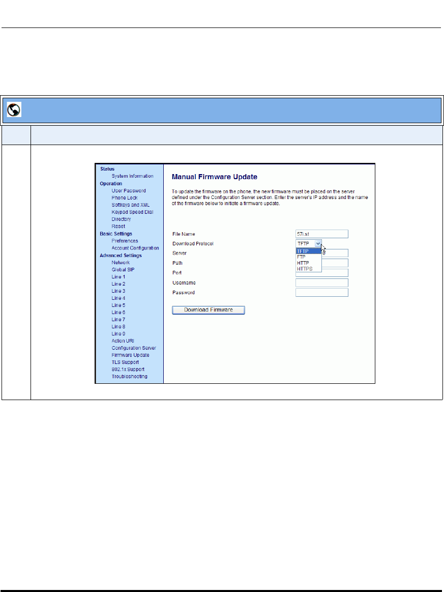
Upgrading the Firmware
41-001160-03, Rev 00, Releaes 2.4 8-3
Upgrading the Firmware
Use the following procedure to manually update the firmware on your
phone from the specified configuration server.
Aastra Web UI
Step Action
1 Click on Advanced Settings->Firmware Update.
Draft 1
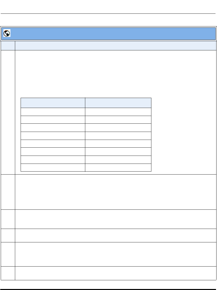
Upgrading the Firmware
8-4 41-001160-03, Rev 00, Releaes 2.4
IP Phone Administrator Guide
2 In the “File Name” field, enter the firmware file name (<phone model>.st) that you want to download
to your IP phone. For example, 53i.st (for a 6753i phone).
Note: This file name must match the actual name of the firmware file residing on your configuration
server.
IMPORTANT: The renamed 675xi phones still use the old naming convention for the .st files. See the
following table.
3 In the “Download Protocol” field, select the protocol from the list to use for downloading the new
firmware. Valid values are:
•TFTP
•FTP
•HTTP
•HTTPS
4 In the “Server” field, enter the IP address in dotted decimal format, of the TFTP configuration server,
or the domain name of the FTP, HTTP, or HTTPS configuration servers (dependant on the protocol
you selected in step 3.) For example: 432.221.45.6.
5 In the “Path” field, enter the path location on the protocol server for where the new firmware resides.
For example, C:\aastra\configserver\firmwareupgrade.
6 In the “Port” field, enter the port number of the protocol server. For example, 80 (for HTTP) or 443
(for HTTPS).
Note: This field is not applicable to the TFTP and FTP protocols.
7 (FTP only) In the “Username ” field, enter the username that is used for authentication when the FTP
server is accessed.
Aastra Web UI
Step Action
IP Phone Model Associated Firmware
9143i 9143i.st
9480i 9480i.st
9480i CT 9480iCT.st
6751i 51i.st
6753i 53i.st
6755i 55i.st
6757i 57i.st
6757i CT 57iCT.st
Draft 1
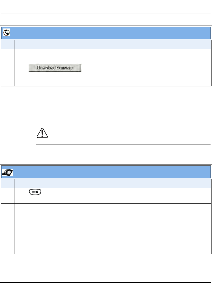
Upgrading the Firmware
41-001160-03, Rev 00, Releaes 2.4 8-5
Upgrading the Firmware
Using the Restart Feature
Restarting the phone forces the phone to check for both firmware and
configuration files stored on the configuration server.
Restarting the Phone Using the IP Phone UI
8 (FTP only) In the “Password ” field, enter the password that is used for authentication when the FTP
server is accessed.
9 Click .
This starts the upgrade process. If the upgrade is successful the following message displays on the
screen: "Firmware Upgrade Successful".
Warning: Do not reset or turn off the phone until the download is
complete.
IP Phone UI
Step Action
1 Press on the phone to enter the Options List.
2Select Restart Phone.
3For 9143i, 6751i, 6753i:
Press # to confirm.
Note: To cancel the Restart, press the 3 key.
For 9480i, 9480i CT, 6755i, 6757i, 6757i CT:
Press Restart.
Note: To cancel the Restart, press Cancel.
Aastra Web UI
Step Action
Draft 1

Upgrading the Firmware
8-6 41-001160-03, Rev 00, Releaes 2.4
IP Phone Administrator Guide
Restarting the Phone Using the Aastra Web UI
Aastra Web UI
1 Click on Operation->Reset->Phone.
2 Click to restart the phone.
Draft 1
Upgrading the Firmware
41-001160-03, Rev 00, Releaes 2.4 8-7
Upgrading the Firmware
Using the Auto-Resync Feature
The auto-resync feature on the IP phones allows an administrator to enable the
phone to be updated automatically once a day at a specific time in a 24-hour
period if the files on the server have changed. This feature works with TFTP, FTP,
HTTP, and HTTPS servers. An administrator can enable this feature using the
Aastra Web UI or using the configuration files (aastra.cfg and <mac>.cfg).
An Administrator can enable Auto-Resync using the configuration files or the
Aastra Web UI. In the configuration files you set the following parameters:
• auto resync mode - Determines whether the configuration server
automatically updates the phone’s configuration files only, the firmware only,
both the firmware and configuration files, or disables automatic updates. This
parameter works with TFTP, FTP, HTTP, and HTTPS servers.
• auto resync time - Sets the time of day in a 24-hour period for the IP phone to
be automatically updated. This parameter works with TFTP, FTP, HTTP and
HTTPS servers.
• auto resync max delay - Specifies the maximum time, in minutes, the phone
waits past the scheduled time before starting a checksync.
•auto resync days - Specifies the amount of days that the phone waits between
checksync operations.
In the Aastra Web UI, you can set the following parameters at the path Advanced
Settings->Configuration Server->Auto-Resync:
•Mode
• Time (24 hours)
• Maximum Delay
•Days
Setting the “auto resync max delay” (Maximum Delay) and “auto resync days”
(Days) parameters can greatly reduce the load placed on the configuration server
when downloading configurations.
Note: The automatic update feature works with both encrypted and plain
text configuration files.
Draft 1
Upgrading the Firmware
8-8 41-001160-03, Rev 00, Releaes 2.4
IP Phone Administrator Guide
Enabling Auto-Resync Using the Configuration Files
Use the following procedure to configure automatic updates of the IP phone
firmware, configuration files, or both.
.
Configuration Files
For specific parameters you can set in the configuration files for automatic update, see Appendix A, the
section, “Configuration Server Settings” on page A-18.
Notes:
1. If a user is accessing the Aastra Web UI, they are not informed of an
auto-reboot.
2. Any changes made using the Aastra Web UI or the IP phone UI are
not overwritten by an auto-resync update. Auto-resync affects the
configuration files only. However, the settings in the Aastra Web UI take
precedence over the IP phone UI and the configuration files.
3. If the IP phone is in use (not idle) at the time of the resync check, the
reboot occurs when the phone becomes idle.
4. The resync time is based on the local time of the IP phone.
5. Auto-Resync adds up to 15 minutes random time to the configured
time. For example, if the auto resync time parameter is set to 02:00, the
event takes place any time between 02:00 and 02:15. This prevents
several phones from accessing the server at the exact same time.
6. The automatic update feature works with both encrypted and plain
text configuration files.
Draft 1
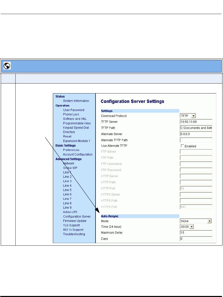
Upgrading the Firmware
41-001160-03, Rev 00, Releaes 2.4 8-9
Upgrading the Firmware
Enabling Auto-Resync Using the Aastra Web UI
Use the following procedure to enable auto-resync for the phones in your
network.
Aastra Web UI
Step Action
1 Click on Advanced Settings->Configuration Server->Auto-Resync.
Auto-Sync
Parameters
Draft 1
Upgrading the Firmware
8-10 41-001160-03, Rev 00, Releaes 2.4
IP Phone Administrator Guide
2 In the “Mode” field, select the auto-resync mode you want to use to automatically update the phone.
Valid values are:
None Disable auto-resync
Configuration Files Updates the configuration files on the IP phone automatically at the specified
time if the files on the server have changed.
Firmware Updates the firmware on the IP phone automatically at the specified time if the
files on the server have changed.
Both Updates the configuration files and firmware automatically at the specified time
if the files on the server have changed.
Notes:
1. If a user is accessing the Aastra Web UI, they are not informed of an auto-reboot.
2. Any changes made using the Aastra Web UI or the IP phone UI are not overwritten by an
auto-resync update. Auto-resync affects the configuration files only. However, the settings in the
Aastra Web UI take precedence over the IP phone UI and the configuration files.
3. The resync time is based on the local time of the IP phone.
4. If the IP phone is in use (not idle) at the time of the resync check, the reboot occurs when the
phone becomes idle.
3 In the “Time (24-hour)” field, select the time that you want the update to take place.
Valid values are 00:00 to 23:30 (in 30 minute increments).
Notes:
1. The resync time is based on the local time of the IP phone.
2. The value of 00:00 is 12:00 A.M.
3. When selecting a value for this parameter in the Aastra Web UI, the values are in 30-minute
increments only.
4. Auto-Resync adds up to 15 minutes random time to the configured time. For example, if the auto
resync time parameter is set to 02:00, the event takes place any time between 02:00 and 02:15.
4 In the “Maximum Delay” field, specify the maximum time, in minutes, the phone waits past the
scheduled time before starting a checksync. The range is 0 to 1439. Default is 15.
5 In the “Days” field, specify the amount of days that the phone waits between checksync operations.
The range is 0 to 364. Default is 0.
Note: A value of 0 causes the phone to checksync every time the clock reads the proper time. A
value of 1 forces the phone to wait 24 hours prior to doing the first checksync.
6 Click to save your settings.
These changes are not dynamic.
You must restart your IP phone for the changes to take affect.
Aastra Web UI
Step Action
Draft 1
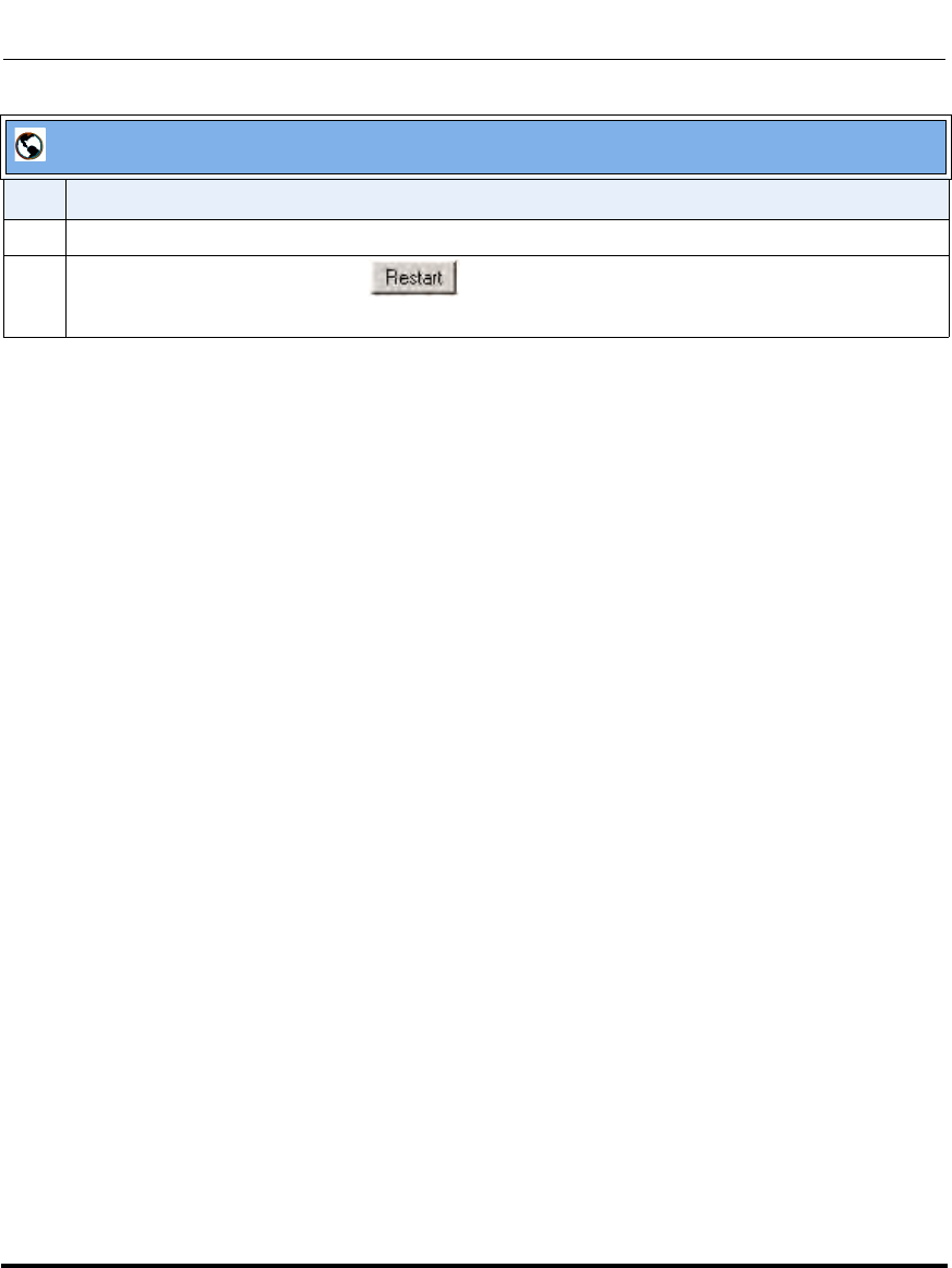
Upgrading the Firmware
41-001160-03, Rev 00, Releaes 2.4 8-11
Upgrading the Firmware
7 Click on Operation->Reset.
8 In the "Restart Phone" field click to restart the IP phone and apply the update.
The update performs automatically at the time you designated.
Aastra Web UI
Step Action
Draft 1

Upgrading the Firmware
8-12 41-001160-03, Rev 00, Releaes 2.4
IP Phone Administrator Guide
Draft 1

Upgrading the Firmware
41-001160-03, Rev 00, Releaes 2.4 8-13
Upgrading the Firmware
Draft 1

Upgrading the Firmware
8-14 41-001160-03, Rev 00, Releaes 2.4
IP Phone Administrator Guide
Draft 1
Draft 1

Upgrading the Firmware
8-16 41-001160-03, Rev 00, Releaes 2.4
IP Phone Administrator Guide
Draft 1

About this chapter
41-001160-03, Rev 00, Releaes 2.4 9-1
Troubleshooting
Chapter 9
Troubleshooting
About this chapter
Introduction
This chapter describes tasks that a system administrator can perform on the IP
phones for troubleshooting purposes. It also includes answers to questions you
may have while using the IP phones.
Topics
This chapter covers the following topics:
Topic Page
Troubleshooting page 9-3
Log Settings page 9-3
Module/Debug Level Settings page 9-4
Support Information page 9-7
WatchDog Task Feature page 9-12
Error Messages Display page 9-15
Troubleshooting Solutions page 9-19
Why does my phone display “Application missing”? page 9-19
Why does my phone display the “No Service” message? page 9-20
Why does my phone display "Bad Encrypted Config"? page 9-20
Why is my phone not receiving the TFTP IP address from the DHCP
Server? page 9-21
Draft 1

About this chapter
9-2 41-001160-03, Rev 00, Releaes 2.4
IP Phone Administrator Guide
How do I restart the IP phone? page 9-22
How do I set the IP phone to factory default? page 9-23
How do I erase the phone’s local configuration? page 9-24
How to reset a user’s password? page 9-25
How do I lock and unlock the phone? page 9-27
Topic Page
Draft 1

Troubleshooting
41-001160-03, Rev 00, Releaes 2.4 9-3
Troubleshooting
Troubleshooting
This section describes tasks that a system administrator can perform on the IP
phones for troubleshooting purposes. Using the Aastra Web UI, a system
administrator can:
• Assign an IP address and IP port in which to save log files
• Filter the logs according to severity that get reported to log files
• Save the current local configuration file to a specified location
• Save the current server configuration file to a specified location
• Show task and stack status (including “Free Memory”and “Maximum
Memory Block Size”)
Aastra Technical Support can then use the information gathered to perform
troubleshooting tasks.
Log Settings
Using the configuration files or the Aastra Web UI, you can specify the location
for which to save files for troubleshooting purposes.
In the configuration files, you use the following parameters to configure log
settings:
•log server ip - The IP address for which to save log files for troubleshooting
purposes.
•log server port - The IP port to use to save log files for troubleshooting
purposes.
•log level - The severity level of the logs to be reported to a log file. Log Level
default is Error (3). (Changes to this parameter via the Aastra Web UI require
a reboot).
Draft 1
Troubleshooting
9-4 41-001160-03, Rev 00, Releaes 2.4
IP Phone Administrator Guide
In the Aastra Web UI, you use the following parameters to configure log
settings:
•Log IP - The IP address for which to save log files for troubleshooting
purposes.
•Log Port - The IP port to use to save log files for troubleshooting purposes.
Reference
For more information about the log setting configuration parameters, see
Appendix A, the section, “Troubleshooting Parameters” on page A-244.
For information about configuring the log settings using the Aastra Web UI, see
“Performing Troubleshooting Tasks” on page 9-8.
Module/Debug Level Settings
The Aastra IP phones provide blog module support that allows enhanced severity
filtering of log calls sent as blog output.
The blog, as used on the IP phones, is a an online debugging tool that can be
frequently updated and intended for technical support analyzation. Blogs are
defined by their format: a series of entries posted to a single page in
reverse-chronological order. The IP Phone blogs are separated into modules
which allow you to log specific information for analyzing.
The following table identifies the blog modules you can set.
Aastra Web UI Parameters Configuration File Parameters
LINMGR (Line Manager information) log module linemgr
UI (User Interface (UI) related) log module user interface
MISC (Miscellaneous) log module misc
SIP (Call control SIP stack) log module sip
DIS (Display drivers) log module dis
DSTORE (Delayed storage) log module dstore
EPT (Endpoint module) log module ept
IND (Indicator module) log module ind
Draft 1
Troubleshooting
41-001160-03, Rev 00, Releaes 2.4 9-5
Troubleshooting
Setting Values for the Module/Debug Levels
There are 6 debug levels for the modules. Each debug level has a value you can
use to turn individual levels ON and OFF. The following table identifies these
debug levels and their values. The value of “1” (fatal errors) is the default setting
for all modules.
KBD (Keyboard module) log module kbd
NET (Network module) log module net
PROVIS (Provisioning module) log module provis
RTPT (Realtime Transport module) log module rtpt
SND (Sound module) log module snd
PROF (Profiler module) log module prof
XML (Extension Markup Lanaguage) log module xml
STUN (Simple Traversal of User Datagram
Protocol (UDP) through Network Address
Translation (NAT)
log module stun
Debug Level Value
Fatal Errors 1 (default)
Errors 2
Warnings 4
Init 8
Functions 16
Info 32
All debug levels
OFF 0
All Debug Levels
ON 65535
Aastra Web UI Parameters Configuration File Parameters
Draft 1

Troubleshooting
9-6 41-001160-03, Rev 00, Releaes 2.4
IP Phone Administrator Guide
Example 1
To turn two or more debug levels on at the same time, you add the value
associated with each level. For example,
Fatal Errors + Errors + Warnings = 1 + 2 + 4 = 7
log module linemgr: 7
log module user interface: 7
log module sip: 7
In the above example, fatal errors, general errors, and warnings are logged for the
line manager, user interface, and SIP call control modules.
Example 2
Functions and Info = 16 + 32 = 48
log module dis: 48
log module net: 48
log module snd: 48
In the above example, functions and general information are logged for the
display drivers, network, and sound modules.
Example 3
log module rtpt: 0
log module ind: 65535
In the above example, all debug levels are OFF for the Real Time Transport
module. All debug levels are ON for the indicator module.
You can set the Module/Debug Levels using the configuration files or the Aastra
Web UI.
Reference
For more information about the debug level configuration parameters, see
Appendix A, the section, “Troubleshooting Parameters” on page A-244.
For information about configuring the log settings using the Aastra Web UI, see
“Performing Troubleshooting Tasks” on page 9-8.
Draft 1
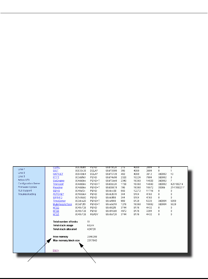
Troubleshooting
41-001160-03, Rev 00, Releaes 2.4 9-7
Troubleshooting
Support Information
You can save the local and/or server configuration files of the IP phone to the
location specified in the "Log Settings" section.
Performing this task allows Aastra Technical Support to view the current
configuration of the IP phone and troubleshoot as necessary.
In the “Support Information” section, you can:
• Get local.cfg
• Get server.cfg
• Show Task and Stack Status
Aastra Technical Support uses this support information for troubleshooting the IP
phone when required.
Using the Aastra Web UI and selecting “Show Task and Stack Status” displays
the tasks and stack status on the IP phone. This screen also displays the Free
Memory and the Max Block Free Memory currently on the phone as shown in
the following illustration. This information is for troubleshooting purposes only.
.
Free Memory Max Memory Block Size
Draft 1

Troubleshooting
9-8 41-001160-03, Rev 00, Releaes 2.4
IP Phone Administrator Guide
Performing Troubleshooting Tasks
Use the following procedures to perform troubleshooting on the IP phone via the
configuration files or the Aastra Web UI.
Configuration Files
For specific parameters you can set in the configuration files, see Appendix A, the section, “Log Settings” on
page A-244.
Draft 1
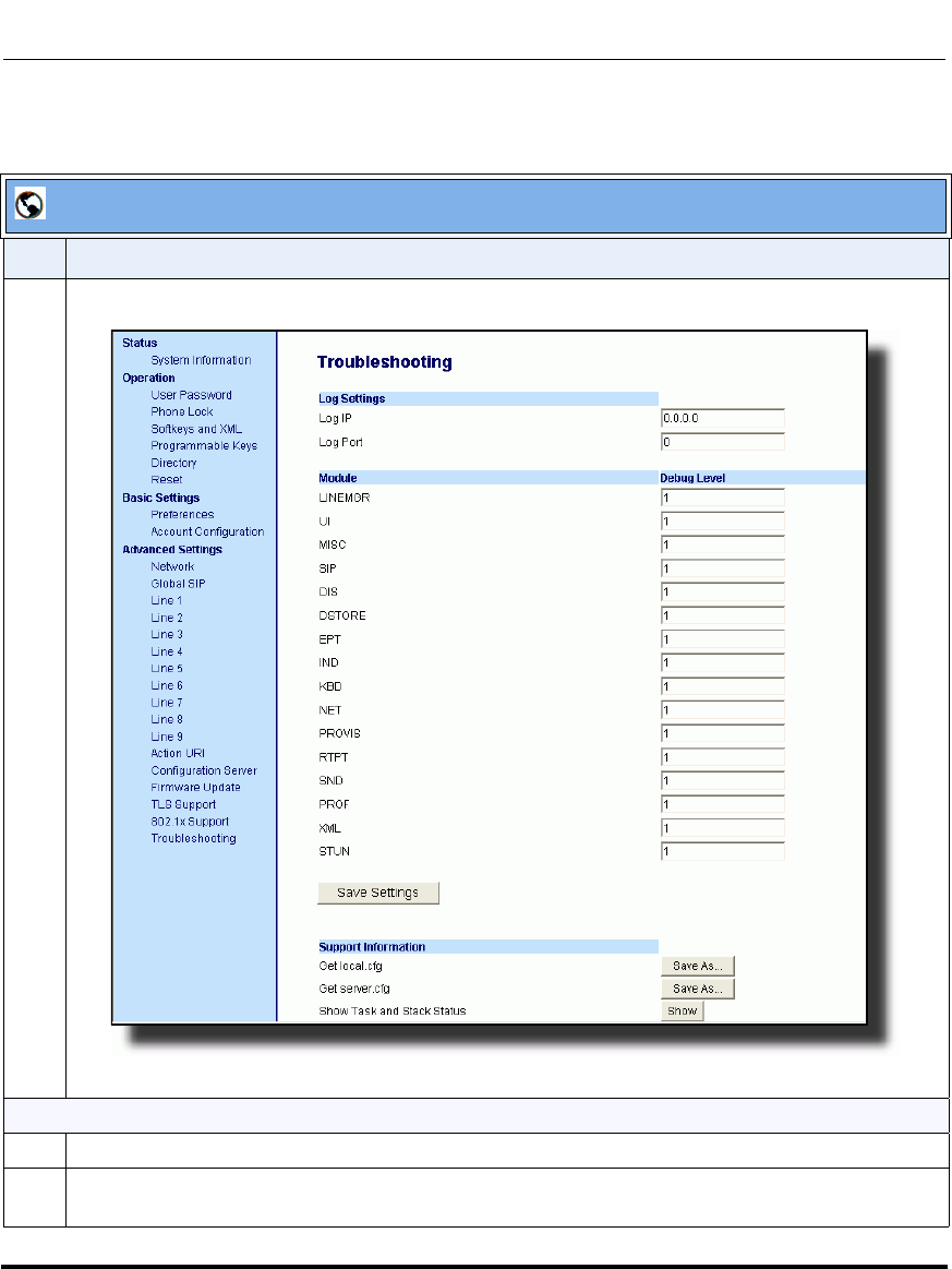
Troubleshooting
41-001160-03, Rev 00, Releaes 2.4 9-9
Troubleshooting
Aastra Web UI
Step Action
1 Click on Advanced Settings->Troubleshooting.
To set log settings:
2 In the "Log IP" field, enter the IP address of where you want log files to be stored.
3In the "Log Port" field, enter the port number associated with the IP address specified in the "Log IP"
field. This port passes the information from the IP phone to the IP address location.
Draft 1
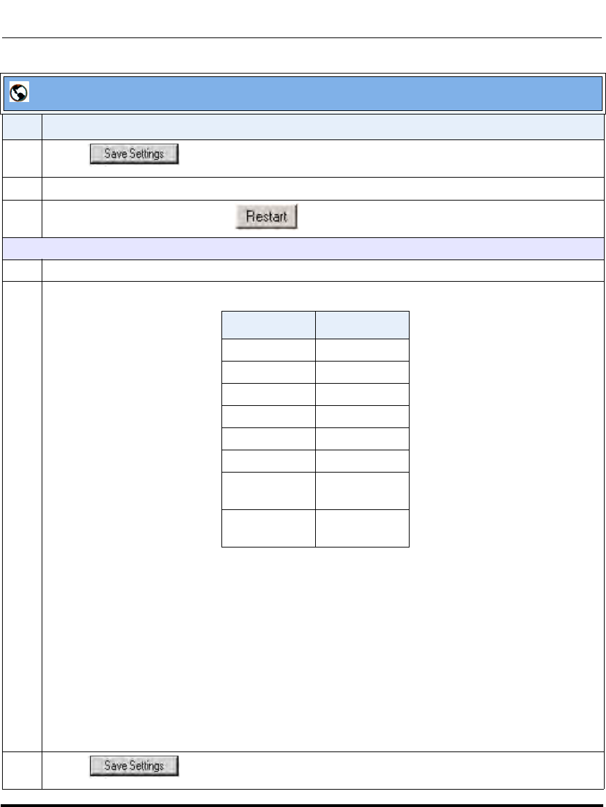
Troubleshooting
9-10 41-001160-03, Rev 00, Releaes 2.4
IP Phone Administrator Guide
4 Click to save your settings.
5 Click on Operation->Reset.
6 In the "Restart Phone" field click to restart the IP phone.
To set blog modules:
7 Select a module for which you want to have log files created, and sent to a blog.
8 Enter a debug level value in the “Debug Level” field for a module. Valid values are:
The value of “0” turns all debug levels OFF for a module. The value of “65535” turns all debug levels
ON for a module.
To turn two or more debug levels on at the same time, you add the value associated with each level.
For example, Fatal Errors + Errors + Warnings = 1 + 2 + 4 = 7
log module linemgr: 7
log module user interface: 7
log module sip: 7
In the above example, fatal errors, general errors, and warnings are logged for the line manager, user
interface, and SIP call control modules.
9 Click to save your settings.
Aastra Web UI
Step Action
Debug Level Value
Fatal Errors 1 (default)
Errors 2
Warnings 4
Init 8
Functions 16
Info 32
All debug
levels OFF 0
All Debug
Levels ON 65535
Draft 1
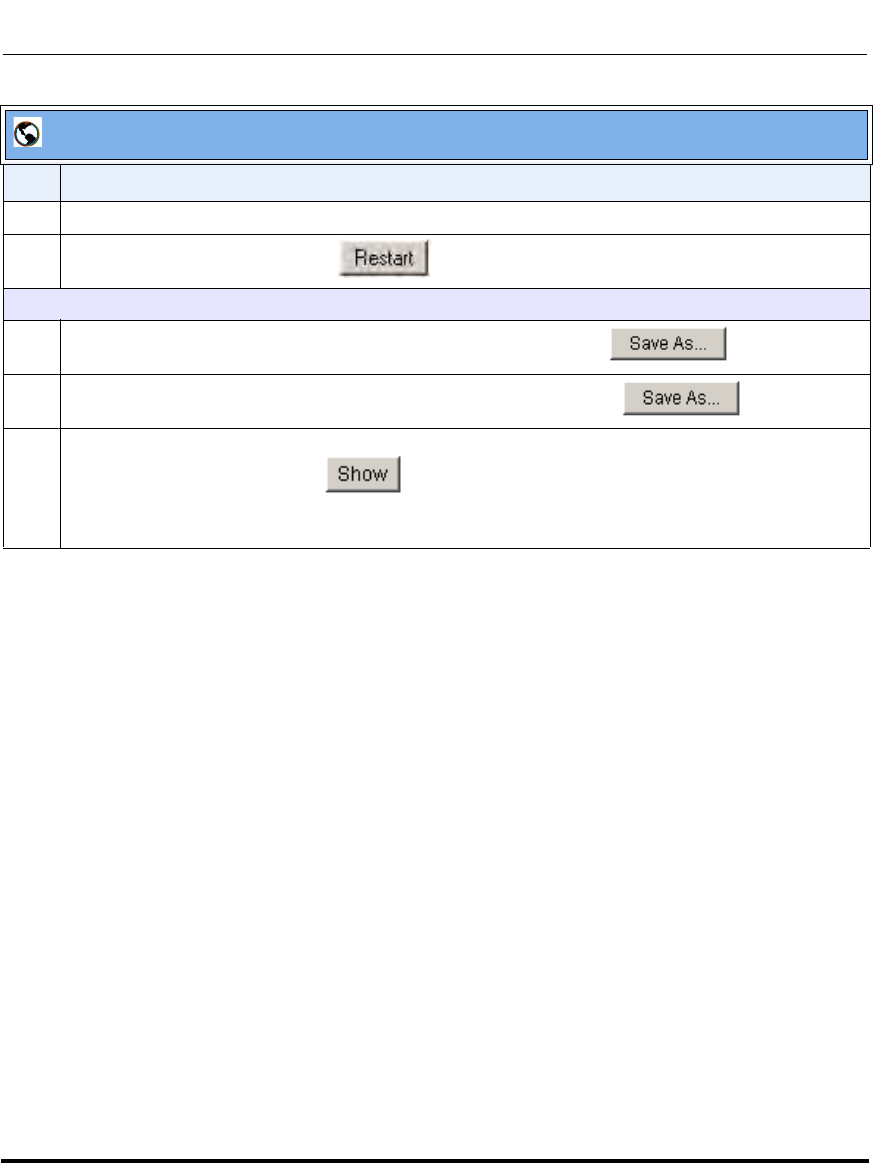
Troubleshooting
41-001160-03, Rev 00, Releaes 2.4 9-11
Troubleshooting
Reference
For information that describes solutions to most common problems using the IP
phones, see the next section, “Troubleshooting Solutions” on page 9-19.
10 Click on Operation->Reset.
11 In the "Restart Phone" field click to restart the IP phone.
To perform support tasks:
12 To store the local configuration file to the specified location, click on in the "Get
local.cfg" field.
13 To store the server configuration file to the specified location, click on in the
"Get server.cfg" field.
14 To display task and stack status information, as well as Free Memory and Maximum Block Free
Memory on the phone, click on in the "Show Task and Stack Status" field.
Note: The local and server configuration file information and the task and stack status information is
for use by Aastra Technical Support for troubleshooting purposes.
Aastra Web UI
Step Action
Draft 1
Troubleshooting
9-12 41-001160-03, Rev 00, Releaes 2.4
IP Phone Administrator Guide
WatchDog Task Feature
The IP Phones include a troubleshooting feature called the “WatchDog” task that
monitors the status of the phones and provides the ability to get stack traces from
the last time the phone failed. When the phone detects a failure (i.e., a crash), it
automatically reboots. You can view a WatchDog crash file using the Aastra Web
UI at the path, Advanced Settings->Troubleshooting. You can enable/disable the
WatchDog task using the configuration files or the Aastra Web UI.
Enabling/Disabling WatchDog
Use the following procedure to enable/disable the WatchDog.
Configuration Files
For specific parameters you can set in the configuration files, see Appendix A, the section, “WatchDog
Settings” on page A-247.
Draft 1
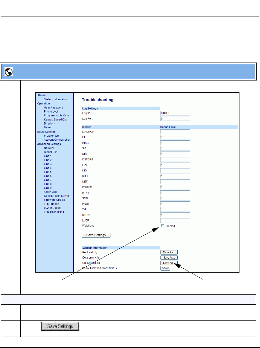
Troubleshooting
41-001160-03, Rev 00, Releaes 2.4 9-13
Troubleshooting
Use the following procedure to enable/disable the WatchDog task for the IP
Phones using the Aastra Web UI. You can also view the “Crash Log” generated by
the WatchDog task using the Aastra Web UI.
Aastra Web UI
1 Click on Advanced Settings->Troubleshooting.
Enable/Disable WatchDog Task
2The “WatchDog” field is enabled by default. To disable the WatchDog task, click in the “Enabled”
box to clear the check mark.
3 Click to save your changes.
Enable/Disable WatchDog View Crash Log
Draft 1

Troubleshooting
9-14 41-001160-03, Rev 00, Releaes 2.4
IP Phone Administrator Guide
View the Crash Log
4 To view a crash log, in the “Get a Crash Log” field, click the SAVE AS button. You can open the
file immediately, or you can save the Crash Log to your PC.
Aastra Web UI
Draft 1

Troubleshooting
41-001160-03, Rev 00, Releaes 2.4 9-15
Troubleshooting
Error Messages Display
An Administrator can view generated error messages that may have occurred
during startup or reboot of the IP Phones. The IP Phone UI has a selection on the
Phone Status page called, “Error Messages” at the location, Options->Phone
Status->Error Messages. The Aastra Web UI also allows you to view these error
messages at the location Advanced Settings->Troubleshooting->Error Messages.
These options allow you to view error messages generated by modules during
startup only (not after registration has completed). You can use this information
for troubleshooting purposes or for reporting the errors to the Administrator.
The IP Phone stores and displays up to 10 error messages (any extra error
messages beyond 10 are discarded). The time and date of each error message also
displays. After a reboot, the previous error messages are discarded and, if
applicable, new error messages display. If there are no error messages during
startup or after a reboot, the message, “No Error Messages” displays on the
screen. Error messages display in the language currently set on the phone.
The following table identifies the possible error messages that may display.
Possible Error Message Description
Bad Certificate A Transport Layer Security (TLS) certificate
is not valid. The invalid certificate can be
any of the following:
• root and intermediate certificate
• local certificate
• private key filename
• trusted certificate
802.1x Startup Failed The Extensible Authentication Protocol TLS
(EAP-TLS) certificates and/or the EAP-MD5
information has failed on the phone.
LLDP Startup Failed Link Layer Discovery Protocol (LLDP) failed
during startup of the phone.
HTTP Connection Manager Init Failed The Hypertext Transfer Protocol (HTTP)
connection manager initialization failed
while updating the configuration on the
phone.
Failed to config Line Manager The configuration of the Line Manager
module on the phone has failed.
Draft 1
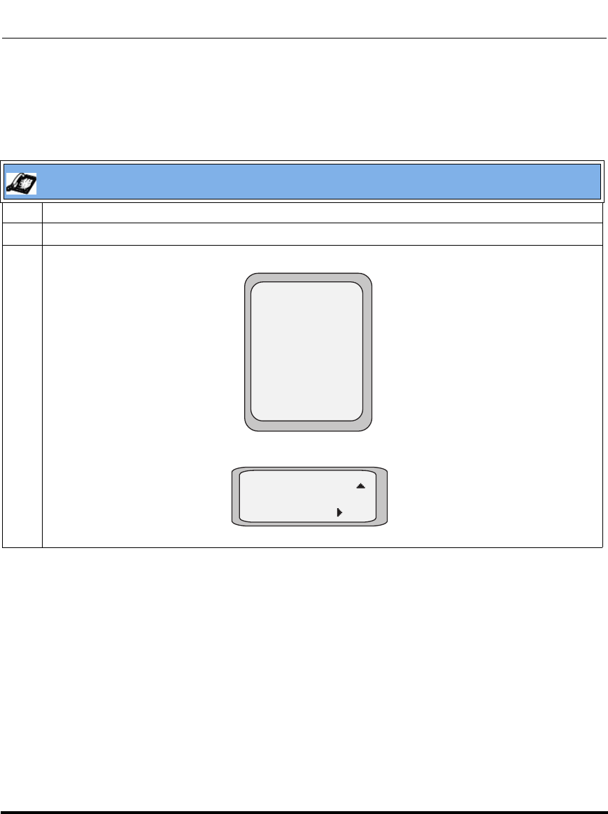
Troubleshooting
9-16 41-001160-03, Rev 00, Releaes 2.4
IP Phone Administrator Guide
Viewing the Error Messages Using the IP Phone UI
Use the following procedure to view the error messages, if any, that generated
during startup.
IP Phone UI
1 Press the Options key on the phone to enter the Options List.
2Select Phone Status.
3Select Error Messages.
6755i, 6757i, 6757i CT
9480i, 9480i CT
6751i, 6753i, 9143i
Phone Status
Done -
- Select
1. IP&MAC Addresses
2. LAN Port
3. PC Port
4. Firmware Info
5. Error Messages
5. Error Messages
Enter
Draft 1
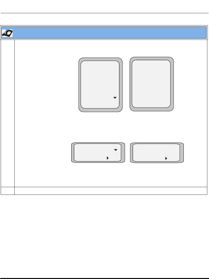
Troubleshooting
41-001160-03, Rev 00, Releaes 2.4 9-17
Troubleshooting
4 If error messages display, use the UP and DOWN navigation keys to view the messages. If no error
message exist, the message, “No Error Messages” displays on the screen.
5 When done viewing, press Done or Exit to exit the Error Messages screen.
IP Phone UI
Error Messages
Done -
No Error Messages
Error Messages
<error message 1>
Fri Aug 4 1:55 pm
<error message 2>
Fri Aug 4 1:57 pm
<error message 3>
Fri Aug 4 2:00 pm
Done -
<error message 1>
Fri Aug 4 2:00 pm
Exit
No Error Messages
Exit
Error Messages No Error Messages
Error Messages No Error Messages
6755i, 6757i, 6757i CT
9480i, 9480i CT
6751i, 6753i, 9143i
Draft 1
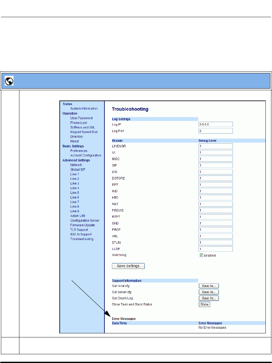
Troubleshooting
9-18 41-001160-03, Rev 00, Releaes 2.4
IP Phone Administrator Guide
Viewing the Error Messages Using the Aastra Web UI
Use the following procedure to view the error messages, if any, that generated
during startup.
Aastra Web UI
1 Click on Advanced Settings->Troubleshooting->Error Messages.
2 Scroll down to the “Error Messages” section to view the error messages that may have generated
during startup or reboot of the IP Phone.
Error Messages
Draft 1

Troubleshooting Solutions
41-001160-03, Rev 00, Releaes 2.4 9-19
Troubleshooting
Troubleshooting Solutions
Description
This section describes solutions to some most common problems that can occur
while using the IP phones.
Why does my phone display “Application missing”?
If you have experienced networking issues while the phone was downloading the
application from the TFTP server, it is possible that the phone can no longer
retrieve the required firmware file. In the event that the phone is no longer able to
communicate with the TFTP server in its attempt to re-download the firmware and
the phone cannot locate the application locally, the message "Application
missing" displays.
The phone also displays the following: “Recovery web-client at: <IP Address>”.
The IP Address displayed is the IP address of the phone. If the phone is unable to
receive an IP from the DHCP server or has lost its record of its static IP, the phone
auto-assigns itself the default IP 192.168.0.50.
To recover the firmware for your phone in this circumstance, please perform the
following:
1. Launch your web browser on your computer.
Note: Your computer needs to be on the same network as your IP Phone.
2. In the URL, type: “http://<IP Address>” (where IP Address is the IP Address
displayed on the phone). Your browser launches the Aastra IP Phone
Firmware Recovery page.
3. Call Customer Support and request a <phone model>.st file.
4. Copy the file to your TFTP server.
5. Enter the <phone model>.st file that is ready for download.
6. Enter the IP address or qualified domain name of the TFTP server.
7. Press the Download Firmware button.
Draft 1

Troubleshooting Solutions
9-20 41-001160-03, Rev 00, Releaes 2.4
IP Phone Administrator Guide
Please ensure that the TFTP server is running and accessible on the network. If the
firmware file is correctly located on the running TFTP server, the phone will
locate the file and reload the application onto the phone.
Why does my phone display the “No Service” message?
The phone displays the “No Service” message if the SIP settings have not been set
up correctly.
The Registrar server could be set to 0.0.0.0. A global value of 0.0.0.0 disables
registration. However, the phone is still active and you can dial using
username@ip address of the phone. The phone displays "No Service".
If the Registrar IP address is set to 0.0.0.0 for a per-line basis (i.e, line 1, line 2,
etc.), then the register request is not sent, the "No Service" message does not
display, and the message waiting indicator (MWI) does not come on.
Check that the "Registrar Server" IP address in the Aastra Web UI at Advanced
Settings->Global SIP is correct. Check the "sip registrar ip" parameter in the
configuration files is correct.
Why does my phone display "Bad Encrypted Config"?
The IP phone displays "Bad Encrypted Config" because encrypted configuration
files are enabled but the decryption process has failed. Specific cases where
decryption fails are:
Reason:
The site-specific password in security.tuz does not match the password used to
encrypt the <mac>.tuz or aastra.tuz files.
Fix:
Encrypt the .cfg files to .tuz using the correct password, or replace the security.tuz
with the correct encrypted file.
Draft 1

Troubleshooting Solutions
41-001160-03, Rev 00, Releaes 2.4 9-21
Troubleshooting
Reason:
Neither of the <mac>.tuz and aastra.tuz files are present on the configuration
server (TFTP/FTP/HTTP).
Fix:
Create the encrypted files using anacrypt.exe and copy them to the configuration
server.
Reason:
The encrypted <mac>.tuz or aastra.tuz file is encrypted using a different version
of anacrypt.exe than the phone firmware.
Fix:
Run "anacrypt.exe -v" and confirm that the correct version is reported, compared
to the phone firmware version.
Why is my phone not receiving the TFTP IP address from the DHCP
Server?
For DHCP to automatically populate the IP address or qualified domain name for
the TFTP server, your DHCP server must support Option 66. Option 66 is
responsible for forwarding the TFTP server IP address or domain name to the
phone automatically. If your DHCP server does not support Option 66, you must
manually enter the IP address or qualified domain name for the TFTP server into
your IP phone configuration.
For procedures on configuring the TFTP server using the IP phone UI and the
Aastra Web UI, see Chapter 4, the section, “Configuring the Configuration Server
Protocol” on page 4-108.
For specific protocol parameters you can set in the configuration files, see
Appendix A, the section, “Configuration Server Settings” on page A-18.
Draft 1
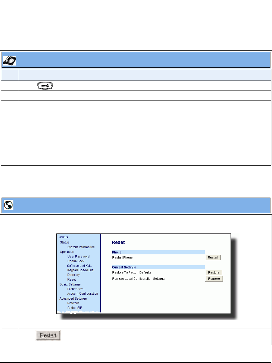
Troubleshooting Solutions
9-22 41-001160-03, Rev 00, Releaes 2.4
IP Phone Administrator Guide
How do I restart the IP phone?
IP Phone UI
Step Action
1 Press on the phone to enter the Options List.
2Select Restart Phone.
3For 9143i, 6751i, 6753i:
Press # to confirm.
Note: To cancel the Restart, press the 3 key.
For 9480i, 9480i CT, 6755i, 6757i, 6757i CT:
Press Restart.
Note: To cancel the Restart, press Cancel.
Aastra Web UI
1 Click on Operation->Reset->Phone.
2 Click to restart the phone.
Draft 1
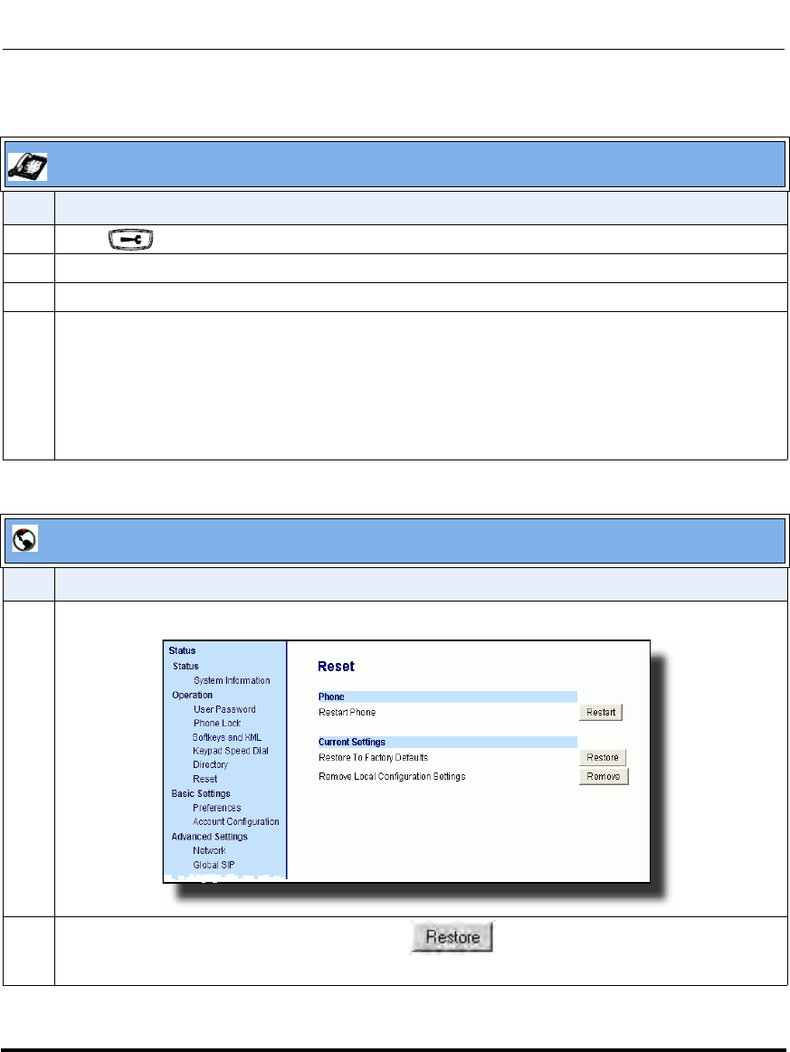
Troubleshooting Solutions
41-001160-03, Rev 00, Releaes 2.4 9-23
Troubleshooting
How do I set the IP phone to factory default?
IP Phone UI
Step Action
1 Press on the phone to enter the Options List.
2Select Administrator Menu and enter your Administrator Password (default is 22222).
3Select Factory Default.
4For 9143i, 6751i, 6753i:
The “Restore Defaults?” prompt displays.
Press # to confirm.
For 9480i, 9480i CT, 6755i/6757i/6757i CT:
The “Reset phone to factory defaults?” prompt displays.
Press Default to confirm.
Aastra Web UI
Step Action
1 Click on Operation->Reset->Current Settings.
2 In the "Restore to Factory Defaults" field, click .
This restores all factory defaults, and removes any saved configuration and directory list files.
Draft 1
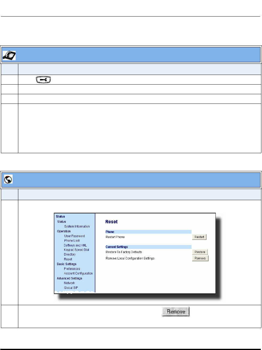
Troubleshooting Solutions
9-24 41-001160-03, Rev 00, Releaes 2.4
IP Phone Administrator Guide
How do I erase the phone’s local configuration?
IP Phone UI
Step Action
1 Press on the phone to enter the Options List.
2Select Administrator Menu and enter your Administrator Password (default is 22222).
3Select Erase Local Config.
4For 9143i, 6751i, 6753i:
The “Erase local config?” prompt displays.
Press # to confirm.
For 9480i, 9480i CT, 6755i, 6757i, 6757i CT:
The “Erase local config?” prompt displays.
Press Erase to confirm.
Aastra Web UI
Step Action
1 Click on Operation->Reset->Current Settings.
2 In the "Remove Local Configuration Settings" field, click .
This removes the last customized configuration settings made on the phone.
Draft 1
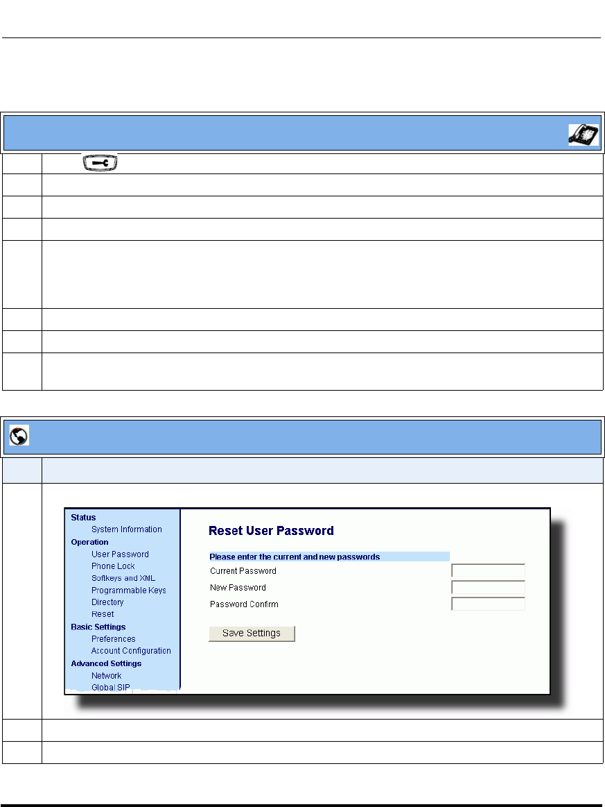
Troubleshooting Solutions
41-001160-03, Rev 00, Releaes 2.4 9-25
Troubleshooting
How to reset a user’s password?
IP Phone UI
1 Press on the phone to enter the Options List.
2Select User Password.
3 Enter the current user password.
4 Press Enter.
5 Enter the new user password.
Note: The IP phones support numeric characters only in passwords. If you enter a password with
alpha characters, the phone uses the default password instead.
6 Press Enter.
7 Re-enter the new user password.
8 Press Enter.
A message, "Password Changed" displays on the screen.
Aastra Web UI
Step Action
1 Click on Operation->User Password.
2 In the "Current Password" field, enter the current user password.
3 In the "New Password" field, enter the new user password.
Draft 1

Troubleshooting Solutions
9-26 41-001160-03, Rev 00, Releaes 2.4
IP Phone Administrator Guide
4 In the "Confirm Password" field, enter the new user password again.
5 Click to save your changes.
Aastra Web UI
Step Action
Draft 1
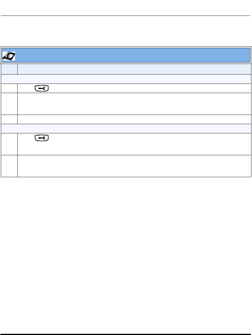
Troubleshooting Solutions
41-001160-03, Rev 00, Releaes 2.4 9-27
Troubleshooting
How do I lock and unlock the phone?
IP Phone UI
Step Action
Lock the phone:
1 Press on the phone to enter the Options List.
2Select Phone Lock.
The prompt, “Lock the phone?” displays.
3Press Lock to lock the phone.
Unlock the phone:
1 Press on the phone to enter the Options List.
The prompt, “To unlock the phone...Password:”
2 Enter the user or administrator password and press Enter.
The phone unlocks.
Draft 1
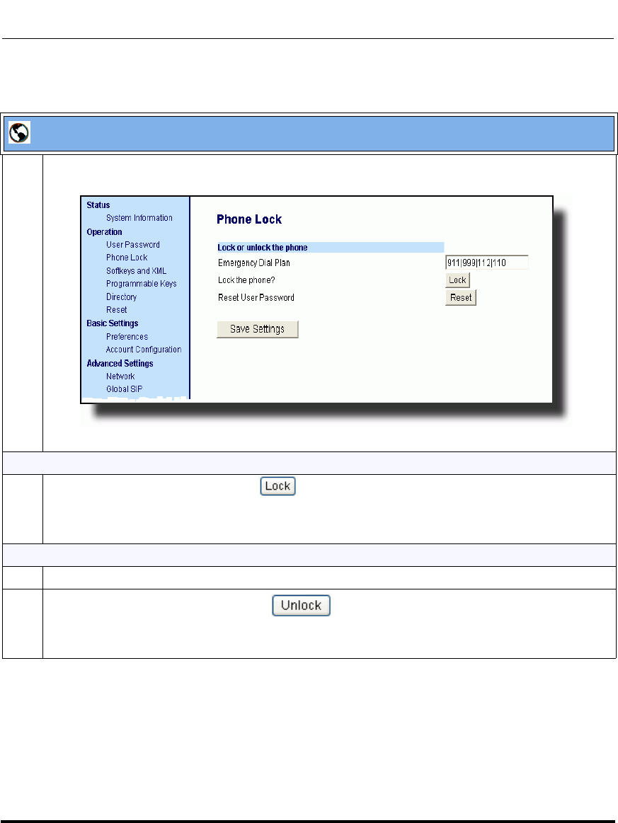
Troubleshooting Solutions
9-28 41-001160-03, Rev 00, Releaes 2.4
IP Phone Administrator Guide
Aastra Web UI
1 Click on Operation->Phone Lock.
Lock the phone:
2 In the “Lock the Phone?” field, click .
The phone locks dynamically and displays the following message:
“Phone is locked”.
Unlock the phone:
3 Click on Operation->Phone Lock.
4 In the “Unlock the Phone?” field, click .
The phone unlocks dynamically and displays the following message:
“Phone is unlocked”.
Draft 1

About this appendix
41-001160-03, Rev 00, Release 2.4 A-1
Appendix A
Configuration Parameters
About this appendix
Introduction
This appendix describes the parameters you can set in the configuration files for
the IP phones. The configuration files include <mac.cfg> and config.cfg.
Topics
This appendix covers the following topics:
Topic Page
Setting Parameters in Configuration Files page A-6
Operational, Basic, and Advanced Parameters page A-7
Simplified IP Phone UI Options Menu page A-7
Network Settings page A-8
DHCP Option Settings page A-13
Password Settings page A-15
Emergency Dial Plan Settings page A-16
Aastra Web UI Settings page A-17
Configuration Server Settings page A-18
Network Address Translation (NAT) Settings page A-29
Draft 1

About this appendix
A-2 41-001160-03, Rev 00, Release 2.4
IP Phone Administrator Guide
Rport Setting page A-31
Local SIP UDP/TCP Port Setting page A-32
Local SIP TLS Port page A-32
HTTPS Client and Server Settings page A-33
HTTPS Server Certificate Validation Settings page A-35
UPnP Settings page A-37
Virtual Local Area Network (VLAN) Settings page A-38
Type of Service (ToS)/DSCP Settings page A-44
Time and Date Settings page A-45
Time Server Settings page A-52
Custom Time Zone and DST Settings page A-54
Backlight Mode Settings (9480i, 9480i CT, 6755i, 6757i, 6757i CT) page A-63
Live Dialpad Settings page A-64
SIP Local Dial Plan Settings page A-65
SIP Basic, Global Settings page A-67
SIP Basic, Per-Line Settings page A-76
BLA Support for MWI page A-87
Centralized Conferencing Settings page A-88
SIP Join Feature for 3-Way Conference page A-90
HTTP/HTTPS Authentication Support for Broadsoft CMS page A-91
Advanced SIP Settings page A-92
Missed Call Summary Subscription Settings page A-101
As-Feature-Event Subscription Settings page A-104
Transport Layer Security (TLS) Settings page A-105
802.1x Support Settings page A-109
RTP, Codec, DTMF Global Settings page A-114
Autodial Settings page A-119
Voicemail Settings page A-122
Directory Settings page A-123
Callers List Settings page A-124
Customize Callers List and Services Key page A-125
Topic Page
Draft 1

About this appendix
41-001160-03, Rev 00, Release 2.4 A-3
Call Forward Settings page A-126
Call Forward Key Mode Settings page A-127
LLDP-MED and ELIN Settings page A-129
Missed Calls Indicator Settings page A-131
XML Settings page A-132
Action URI Settings page A-135
XML SIP Notify Settings page A-141
Polling Action URI Settings page A-142
Ring Tone and Tone Set Global Settings page A-143
Ring Tone Per-Line Settings page A-145
Incoming Call Interrupts Dialing Setting page A-146
Switch Focus to Ringing Line page A-148
Preferred Line and Preferred Line Timeout page A-149
Goodbye Key Cancels Incoming Call page A-150
Stuttered Dial Tone Setting page A-151
Call Waiting Settings page A-152
Message Waiting Indicator Settings page A-153
DND Key Mode Settings page A-154
Priority Alert Settings page A-155
Bellcore Cadence Settings page A-160
Language Settings page A-162
Language Pack Settings page A-164
Suppress DTMF Playback Setting page A-173
Display DTMF Digits Setting page A-174
Intercom, Auto-Answer, and Barge In Settings page A-175
Group Paging RTP Settings page A-179
Audio Transmit and Receive Gain Adjustment Settings page A-180
Directed Call Pickup (BLF or XML Call Interception) Settings page A-184
ACD Auto-Available Timer Settings page A-186
Park and Pickup Global Settings (9480i, 9480i CT, 6757i/6757i CT only) page A-187
Mapping Key Settings page A-189
Topic Page
Draft 1

About this appendix
A-4 41-001160-03, Rev 00, Release 2.4
IP Phone Administrator Guide
Softkey/Programmable Key/Feature Key/Expansion Module Key Parameters page A-192
Softkey Settings for 9480i, 9480i CT, 6755i, 6757i, 6757i CT page A-193
Programmable Key Settings for 9143i, 6753i, and 6755i page A-202
Top Softkey Settings for 6757i and 6757i CT page A-207
Handset Feature Key Settings for the 9480i CT and 6757i CT page A-214
Expansion Module Key Settings for M670i (6753i, 6755i, 6757i, 6757i CT) and M675i
(for 6755i, 6757i, 6757i CT) page A-216
Customizing the Key Type List page A-223
Locking Softkeys and Programmable Keys page A-226
Locking the SAVE and DLETE Keys (6753i) page A-229
Enabling/Disabling Ability to Add/Edit Speeddial Keys page A-230
BLF List URI Settings page A-230
Customizing M675i Expansion Module Column Display page A-231
Expansion Module 1 through 3 page A-231
Advanced Operational Parameters page A-233
Blind Transfer Setting page A-233
Update Caller ID Setting. page A-233
Boot Sequence Recovery Mode Settings. page A-234
Single Call Restriction Setting page A-235
Blacklist Duration Setting page A-236
Whitelist Proxy Setting page A-236
XML Key Redirection Settings (for Redial, Xfer, Conf, Icom, Voicemail) page A-237
Options Key Redirection Setting (Services key on 6751i) page A-239
Off-Hook and XML Application Interaction Setting page A-239
XML Override for a Locked Phone Setting page A-240
Symmetric UDP Signaling Setting page A-240
User-Agent Setting page A-241
GRUU and sip.instance Support page A-241
DNS Query Setting page A-242
Ignore Out of Order SIP Requests page A-243
Configuration Encryption Setting page A-243
Topic Page
Draft 1


Setting Parameters in Configuration Files
A-6 41-001160-03, Rev 00, Release 2.4
IP Phone Administrator Guide
Setting Parameters in Configuration Files
You can set specific configuration parameters in the configuration files for
configuring you IP phone. The aastra.cfg and <mac>.cfg files are stored on the
server. The aastra.cfg file stores global IP phone configuration settings. The
<mac>.cfg file stores configuration settings specific to the IP phone with that
MAC address. When you restart the IP phone, these files are downloaded to the
phone.
If you make changes to the phone configuration, the changes are stored in a local
configuration on the phone (not on the server).
Configuration changes made to the <mac>.cfg file override the configuration
settings in the aastra.cfg file.
Reference
For information about configuration file precedence, see Chapter 1, the section,
“Configuration File Precedence” on page -38.
This section includes the following types of configurable parameters:
•Operational, Basic, and Advanced Parameters on page A-7
•Mapping Key Settings on page A-189
•Softkey/Programmable Key/Feature Key/Expansion Module Key Parameters
on page A-192
•Advanced Operational Parameters on page A-233
•Troubleshooting Parameters on page A-244
Note: Configuration parameters that you enter in the configuration files
are NOT case sensitive.
Draft 1
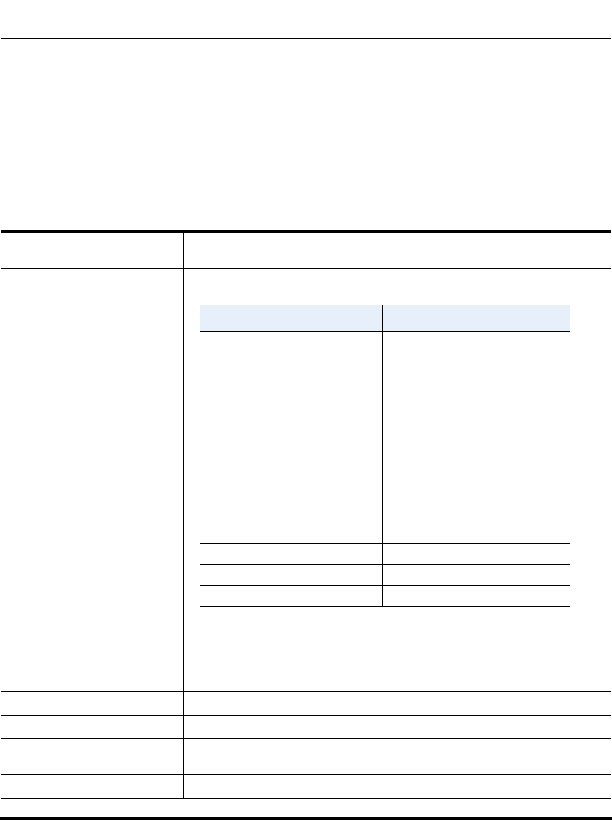
Operational, Basic, and Advanced Parameters
41-001160-03, Rev 00, Release 2.4 A-7
Operational, Basic, and Advanced Parameters
The following sections provide the configuration parameters you can configure on
the IP phone. Each parameter table includes the name of the parameter, a
description, the format, default value, range, and example. The table also provides
the method for which the parameters can be configured (IP phone UI, Aastra Web
UI, or configuration files).
Simplified IP Phone UI Options Menu
Parameter –
options simple menu Configuration Files aastra.cfg, <mac>.cfg
Description Allows you to enable a simplified options menu or enable the full menu on
the IP Phone UI.
Warning: When using the simplified menu, you cannot change the
Network settings from the IP Phone UI. If the network settings become
misconfigured, you must “factory default” the phone and use the full menu
to recover the network settings from the Phone UI OR use the Aastra
Web UI to configure the network settings.
Format Boolean
Default Value 0 (full options menu)
Range 0 (full options menu)
1 (simplified options menu)
Example options simple menu: 1
Full Options Menu Simplified Options Menu
Call Forward Call Forward
Preferences Preferences
Only the following display:
Services (9143i, 6751i, and
6753i)
Tones
Contrast Level
Live Dialpad
Set Audio (9480i, 9480i CT,
6755i, 6757i, 6757i CT only)
Handset Pairing (9480i CT and
6757i CT)
Phone Status Phone Status
User Password Removed
Administrator Menu Removed
Restart Phone Removed
Phone Lock Phone Lock
Draft 1

Operational, Basic, and Advanced Parameters
A-8 41-001160-03, Rev 00, Release 2.4
IP Phone Administrator Guide
Network Settings
Parameter –
dhcp
DHCP
(in Web UI)
IP phone UI Options->Administrator Menu->
Network Settings
Aastra Web UI Advanced Settings->Network->
Basic Network Settings
Configuration Files aastra.cfg, <mac>.cfg
Description Enables or disables DHCP. Enabling DHCP populates the required
network information. The DHCP server serves the network information
that the IP phone requires. If the IP phone is unable to get any required
information, then you must enter it manually. DHCP populates the
following network information:
IP Address, Subnet Mask, Gateway,, Domain Name Servers (DNS),
TFTP, HTTP, HTTP Port, HTTPS, HTTPS Port, and FTP servers, and
Timer Servers.
Note: For DHCP to automatically populate the IP address or qualified
domain name for the TFTP server, your DHCP server must support
Option 66.
Format Integer
Default Value 1 (enabled)
Range 0 (disabled)
1 (enabled)
Example dhcp: 1
Parameter –
ip
Ip Address
(in Web UI)
IP phone UI Options->Administrator Menu->
Network Settings
Aastra Web UI Advanced Settings->Network->
Basic Network Settings
Configuration Files aastra.cfg, <mac>.cfg
Description This parameter assigns a static IP address to the IP phone device.
Note: For DHCP to automatically populate this parameter, your DHCP
server must support Option 66.
Format IP address
Default Value 0.0.0.0
Range Not Applicable
Example ip: 192.168.0.25
Draft 1

Operational, Basic, and Advanced Parameters
41-001160-03, Rev 00, Release 2.4 A-9
Parameter –
subnet mask
Subnet Mask
(in Web UI)
IP phone UI Options->Administrator Menu->
Network Settings
Aastra Web UI Advanced Settings->Network->
Basic Network Settings
Configuration Files aastra.cfg, <mac>.cfg
Description Subnet mask defines the IP address range local to the IP phone.
Note: For DHCP to automatically populate this parameter, your DHCP
server must support Option 66.
Format IP address
Default Value 255.255.255.0
Range Not Applicable
Example subnet mask: 255.255.255.224
Parameter –
default gateway
Gateway
(in Web UI)
IP phone UI Options->Administrator Menu->
Network Settings
Aastra Web UI Advanced Settings->Network->
Basic Network Settings
Configuration Files aastra.cfg, <mac>.cfg
Description The IP address of the network’s gateway or default router IP address.
Note: For DHCP to automatically populate this parameter, your DHCP
server must support Option 66.
Format IP address
Default Value 1.0.0.1
Range Not Applicable
Example default gateway: 192.168.0.1
Draft 1

Operational, Basic, and Advanced Parameters
A-10 41-001160-03, Rev 00, Release 2.4
IP Phone Administrator Guide
Parameter –
dns1
Primary DNS
(in Web UI)
IP phone UI Options->Administrator Menu->
Network Settings
Aastra Web UI Advanced Settings->Network->
Basic Network Settings
Configuration Files aastra.cfg, <mac>.cfg
Description Primary domain name server IP address. For any of the IP address
settings on the IP phone a domain name value can be entered instead of
an IP address. With the help of the domain name servers the domain
names for such parameters can then be resolved to their corresponding
IP addresses.
Note: For DHCP to automatically populate this parameter, your DHCP
server must support Option 66.
Format IP address
Default Value 0.0.0.0
Range Not Applicable
Example dns1: 192.168.0.5
Parameter –
dns2
Secondary DNS
(in Web UI)
IP phone UI Options->Administrator Menu->
Network Settings
Aastra Web UI Advanced Settings->Network->
Basic Network Settings
Configuration Files aastra.cfg, <mac>.cfg
Description A service that translates domain names into IP addresses. To assign
static DNS addresses, disable DHCP.
Note: For DHCP to automatically populate this parameter, your DHCP
server must support Option 66.
Format IP address
Default Value 0.0.0.0
Range Not Applicable
Example dns2: 192.168.0.6
Draft 1

Operational, Basic, and Advanced Parameters
41-001160-03, Rev 00, Release 2.4 A-11
Parameter –
ethernet port 0
LAN Port
(in Web UI)
IP phone UI Options->Administrator Menu->
Network Settings
Aastra Web UI Advanced Settings->Network->
Basic Network Settings
Configuration Files aastra.cfg, <mac>.cfg
Description The send (TX) and receive (RX) method to use on Ethernet port 0 to
transmit and receive data over the LAN.
Format Integer
Default Value 0
Range 0 - auto-negotiate
1 - full-duplex, 10Mbps
2 - full-duplex, 100Mbps
3 - half-duplex, 10Mbps
4 - half-duplex, 100Mbps
Example lan port: 1
Parameter –
ethernet port 1
PC Port
(in Web UI)
IP phone UI Options->Administrator Menu->
Network Settings
Aastra Web UI Advanced Settings->Network->
Basic Network Settings
Configuration Files aastra.cfg, <mac>.cfg
Description The send (TX) and receive (RX) method to use on Ethernet port 1 to
transmit and receive data over the LAN.
Format Integer
Default Value 0
Range 0 - auto-negotiate
1 - full-duplex, 10Mbps
2 - full-duplex, 100Mbps
3 - half-duplex, 10Mbps
4 - half-duplex, 100Mbps
Example ethernet port 1: 2
Draft 1

Operational, Basic, and Advanced Parameters
A-12 41-001160-03, Rev 00, Release 2.4
IP Phone Administrator Guide
Parameter –
pc port passthru enabled IP phone UI Options->Administrator Menu->
Network Settings->Ethernet Link
Aastra Web UI Advanced Settings->Network->
Basic Network Settings
Configuration Files aastra.cfg, <mac>.cfg
Description Enables or disables the PC port on the phone to be used for 802.1x
authentication support.
Note: For more information about configuring 802.1x support on the IP
phones, see “802.1x Support Settings” on page A-109.
Format Integer
Default Value 1 (enable)
Range 0 (disable)
1 (enable)
Example pc port passthru enabled: 1
Draft 1

Operational, Basic, and Advanced Parameters
41-001160-03, Rev 00, Release 2.4 A-13
DHCP Option Settings
Option 12
Option 77
Parameter–
hostname
Hostname
(in Web UI)
Configuration Files aastra.cfg, <mac>.cfg
IP Phone UI Options->Administrator Menu->
Network Settings->Hostname
Aastra Web UI Advanced Settings->Network->
Basic Network Settings
Description Specifies the hostname DHCP Option 12 that the phone sends with the
DHCP Request packet.
Note: If you change this parameter, you must restart your phone for the
change to take affect.
Format String
Default Value [<model><MAC IP Address>]
Range Up to 64 alpha-numeric characters
Note: The value for this parameter can also be a fully qualified domain
name.
Example hostname: aastra4
Parameter–
dhcp userclass
DHCP User Class
(in Web UI)
Configuration Files aastra.cfg, <mac>.cfg
IP Phone UI Options->Administrator Menu->
Network Settings->DHCP Settings->
DHCP User Class
Aastra Web UI Advanced Settings->Network->
Advanced Network Settings
Description Specifies the User Class DHCP Option 77 that the phone sends to the
configuration server with the DHCP Request packet.
Note: If you specify a value for this parameter, you must restart your phone
for the change to take affect. Any change in its value during start-up results
in an automatic reboot.
Format String
Default Value ““
Range Up to 64 alpha-numeric characters
Example dhcp userclass: admin
Draft 1

Operational, Basic, and Advanced Parameters
A-14 41-001160-03, Rev 00, Release 2.4
IP Phone Administrator Guide
Options 159 and 160 - DHCP Option Override
Parameter–
dhcp config option
override
DHCP Download Options
(in Web UI)
Configuration Files aastra.cfg, <mac>.cfg
IP Phone UI Options->Administrator Menu->
Network Settings->DHCP Settings->
Download Options
Aastra Web UI Advanced Settings->Network->
Advanced Network Settings
Description The value specified for this parameter overrides the precedence order for
determining a configuration server.
Note: You must restart the IP Phone for this parameter to take affect.
Format Integer
Default Value 0 (Any - no override - uses normal precedence order of 43, 160, 159, 66)
Range -1 (Disabled - ignores all DHCP configuration options (43, 66, 159, 160)
0 (Any)
43
66
159
160
Example dhcp config option override: 66
Draft 1

Operational, Basic, and Advanced Parameters
41-001160-03, Rev 00, Release 2.4 A-15
Password Settings
Parameter –
admin password Configuration Files aastra.cfg, <mac>.cfg
Description Allows you to set a new administrator password for the IP phone.
Note: The IP phones support numeric characters only in passwords. If you
enter a password with alpha characters, the phone uses the default
password instead.
Format Integer
Default Value 22222
Range 0 to 4294967295
Example admin password: 1234567890
Parameter –
user password
Current Password
(in Web UI)
IP phone UI Options->User Password
Aastra Web UI Operation->User Password
Configuration Files aastra.cfg, <mac>.cfg
Description Allows you to set a new user password for the IP phone.
Note: The IP phones support numeric characters only in passwords. If you
enter a password with alpha characters, the phone uses the default
password instead.
Format Integer
Default Value Default value is an empty string ““ (left blank)
Range 0 to 4294967295
Example user password: 123
Draft 1

Operational, Basic, and Advanced Parameters
A-16 41-001160-03, Rev 00, Release 2.4
IP Phone Administrator Guide
Emergency Dial Plan Settings
Parameter –
emergency dial plan Configuration Files aastra.cfg, <mac>.cfg
Aastra Web UI Operation->Phone Lock
Description Allows you to specify an emergency number to use on your IP phone so a
caller can contact emergency services in the local area when required.
The default emergency numbers on the IP phones is 911, 999, 112, and
110.
911 - A United States emergency number.
999 - A United Kingdom emergency number.
112 - An international emergency telephone number for GSM mobile
phone networks. In all European Union countries it is also the
emergency telephone number for both mobile and fixed-line
telephones.
110 - A police and/or fire emergency number in Asia, Europe, Middle
East, and South America.
Dial plan(characters) Length (bytes)
911 14
4xx 18
x+#|xx+* 35
911|999|112|110|450 54
911|112|011XX+#|101XX+#|1[2-3]XXXXXXXXX|
[4-5]XXXXXXXXX|[6-7]XXXXXXXXXX,3|
[8-9]XXXXXXXXXXX,2|XX+*|XX+#|
*XXX+#|#XX+#|4xx,2 325
Note: Contact your local phone service provider for available emergency
numbers in your area.
Format Integer
Default Value x+#|xx+*
Range Up to 512 characters
Example emergency dial plan: 911|999
Draft 1

Operational, Basic, and Advanced Parameters
41-001160-03, Rev 00, Release 2.4 A-17
Aastra Web UI Settings
Parameter –
options password enabled Configuration Files aastra.cfg, <mac>.cfg
Description Enables or disables password protection of the Options key on the IP
phone. If enabled, upon pressing the Options key, a user has to enter a
password at the IP phone UI. If the password is entered correctly, the user
is allowed to gain access to the Options Menu and no more password
prompts display for other password protected screens. If the user fails to
enter the correct password in three attempts, access to the Options Menu
is denied and the IP phone returns to the idle screen.
Note: The password to enter is the administrator password configured for
that phone.
Format Boolean
Default Value 0
Range 0 (false; not password protected)
1 (true; password protected)
Example options password enabled: 1
Parameter –
web interface enabled Configuration Files aastra.cfg, <mac>.cfg
Description Enables or disables the Aastra Web UI for a single IP phone when this
parameter is entered in the <mac>.cfg file.
Enables or disables the Aastra Web UI for all phones when this parameter
is placed in the aastra.cfg file.
Format Boolean
Default Value Not Applicable
Range 0 = Disable
1 = Enable
Example web interface enabled: 1
Draft 1

Operational, Basic, and Advanced Parameters
A-18 41-001160-03, Rev 00, Release 2.4
IP Phone Administrator Guide
Configuration Server Settings
Parameter –
download protocol
Download Protocol
(in Web UI)
IP phone UI Options->Administrator Menu->
Network Settings
Aastra Web UI Advanced Settings->Configuration Server
Configuration Files aastra.cfg, <mac>.cfg
Description Protocol to use for downloading new versions of software to the IP phone.
Format Text
Default Value TFTP
Range TFTP
FTP
HTTP
HTTPS
Example download protocol: HTTPS
Parameter –
tftp server
TFTP Server
(in Web UI)
IP phone UI Options->Administrator Menu->
Network Settings->TFTP Server->Primary TFTP
Aastra Web UI Advanced Settings->Configuration Server
Configuration Files aastra.cfg, <mac>.cfg
Description The TFTP server’s IP address. If DHCP is enabled and the DHCP server
provides the information, this field is automatically populated. Use this
parameter to change the IP address or domain name of the TFTP server.
This will become effective after this configuration file has been downloaded
into the phone.
Note: For DHCP to automatically populate this parameter, your DHCP
server must support Option 66.
Format IP address or qualified domain name
Default Value 0.0.0.0
Range Not Applicable
Example tftp server: 192.168.0.130
Draft 1

Operational, Basic, and Advanced Parameters
41-001160-03, Rev 00, Release 2.4 A-19
Parameter –
tftp path Aastra Web UI Advanced Settings->
Configuration Server->Settings
IP Phone UI Options->Administrator Menu->
Configuration Server->TFTP Settings
Configuration Files aastra.cfg, <mac>.cfg
Description Specifies the path name for which the configuration files reside on the
TFTP server for downloading to the IP Phone.
Note: Enter the path name in the form folderX\folderX\folderX. For
example, ipphone\6757i\configfiles.
Format String
Default Value N/A
Range Up to 64 alphanumeric characters
Example tftp path: configs\tftp
Parameter –
alternate tftp server
Alternate TFTP
(in Web UI)
IP phone UI Options->Administrator Menu->
Network Settings->TFTP Server->
Alternate TFTP
Aastra Web UI Advanced Settings->Configuration Server
Configuration Files aastra.cfg, <mac>.cfg
Description The alternate TFTP server’s IP address or qualified domain name. This
will become effective after this configuration file has been downloaded into
the phone.
Format IP address or qualified domain name
Default Value 0.0.0.0
Range Not Applicable
Example alternate tftp server: 192.168.0.132
Draft 1

Operational, Basic, and Advanced Parameters
A-20 41-001160-03, Rev 00, Release 2.4
IP Phone Administrator Guide
Parameter –
alternate tftp path Aastra Web UI Advanced Settings->
Configuration Server->Settings
IP Phone UI Options->Administrator Menu->
Configuration Server->TFTP Settings
Configuration Files aastra.cfg, <mac>.cfg
Description Specifies a path name for which the configuration files reside on an
alternate TFTP server for downloading to the IP Phone.
Note: Enter the path name in the form folderX\folderX\folderX. For
example, ipphone\6757i\configfiles.
Format String
Default Value N/A
Range Up to 64 alphanumeric characters
Example alternate tftp path: configs\alternate
Parameter –
use alternate tftp
Use Alternate TFTP
(in Web UI)
IP phone UI Options->Administrator Menu->
Network Settings->TFTP Server->Select TFTP
Aastra Web UI Advanced Settings->Configuration Server
Configuration Files aastra.cfg, <mac>.cfg
Description Enables or disables the alternate TFTP server. Valid values are "0"
disabled and "1" enabled.
Format Not Applicable
Default Value 0
Range 0 or 1
Example use alternate tftp: 1
Draft 1

Operational, Basic, and Advanced Parameters
41-001160-03, Rev 00, Release 2.4 A-21
Parameter –
ftp server
FTP Server
(in Web UI)
IP phone UI Options->Administrator Menu->
Network Settings->FTP Server
Aastra Web UI Advanced Settings->Configuration Server
Configuration Files aastra.cfg, <mac>.cfg
Description The FTP server’s IP address or network host name. This will become
effective after this configuration file has been downloaded into the phone.
Optional: You can also assign a username and password for access to the
FTP server. See the following parameters for setting username and
password.
Note: For DHCP to automatically populate this parameter, your DHCP
server must support Option 66.
Format IP address or fully qualified Domain Name
Default Value 0.0.0.0
Range Not Applicable
Example ftp server: 192.168.0.131
Parameter –
ftp path Aastra Web UI Advanced Settings->
Configuration Server->Settings
IP Phone UI Options->Administrator Menu->
Configuration Server->FTP Settings
Configuration Files aastra.cfg, <mac>.cfg
Description Specifies a path name for which the configuration files reside on an FTP
server for downloading to the IP Phone.
Note: Enter the path name in the form folderX\folderX\folderX. For
example, ipphone\6757i\configfiles.
Format String
Default Value N/A
Range Up to 64 alphanumeric characters
Example ftp path: configs\ftp
Draft 1

Operational, Basic, and Advanced Parameters
A-22 41-001160-03, Rev 00, Release 2.4
IP Phone Administrator Guide
Parameter –
ftp username
FTP User Name
(in Web UI)
IP phone UI Options->Administrator Menu->
Network Settings->FTP Server
Aastra Web UI Advanced Settings->Configuration Server
Configuration Files aastra.cfg, <mac>.cfg
Description The username to enter for accessing the FTP server. This will become
effective after this configuration file has been downloaded into the phone.
Note: The IP Phones support usernames containing dots (“.”).
Format Text
Default Value Not Applicable
Range Up to 63 alphanumeric characters
Example ftp username: 6757iaastra
Parameter –
ftp password
FTP Password
(in Web UI)
IP phone UI Options->Administrator Menu->
Network Settings->FTP Server
Aastra Web UI Advanced Settings->Configuration Server
Configuration Files aastra.cfg, <mac>.cfg
Description The password to enter for accessing the FTP server. This will become
effective after this configuration file has been downloaded into the phone.
Format Text
Default Value Not Applicable
Range Up to 63 alphanumeric characters
Example ftp password: 1234
Draft 1

Operational, Basic, and Advanced Parameters
41-001160-03, Rev 00, Release 2.4 A-23
Parameter –
http server
HTTP Server
(in Web UI)
IP phone UI Options->Administrator Menu->
Network Settings->HTTP Server
Aastra Web UI Advanced Settings->Configuration Server
Configuration Files aastra.cfg, <mac>.cfg
Description The HTTP server’s IP address. This will become effective after this
configuration file has been downloaded into the phone.
Optional: You can also assign an HTTP relative path to the HTTP server.
See the next parameter (http path).
Note: For DHCP to automatically populate this parameter, your DHCP
server must support Option 66.
Format IP address or fully qualified Domain Name
Default Value 0.0.0.0
Range Not Applicable
Example http server: 192.168.0.132
Parameter –
http path
HTTP Path
(in Web UI)
IP phone UI Options->Administrator Menu->
Network Settings->HTTP Server
Aastra Web UI Advanced Settings->Configuration Server
Configuration Files aastra.cfg, <mac>.cfg
Description The HTTP path name to enter.
If the IP phone’s configuration and firmware files are located in a
sub-directory beneath the server’s HTTP root directory, the relative path
to that sub-directory should be entered in this field.
Format dir/dir/dir
Default Value Not Applicable
Range Up to 63 alphanumeric characters
Example http path: ipphones/6757i
Draft 1

Operational, Basic, and Advanced Parameters
A-24 41-001160-03, Rev 00, Release 2.4
IP Phone Administrator Guide
Parameter –
http port
HTTP Port
(in Web UI)
IP Phone UI: Options->Administrator Menu->
Configuration Server->HTTP Settings
Aastra Web UI: Advanced Settings->Configuration Server->
Settings
Configuration Files aastra.cfg, <mac>.cfg
Description Specifies the HTTP port that the server uses to load the configuration to
the phone over HTTP.
Note: For DHCP to automatically populate this parameter, your DHCP
server must support Option 66.
Format Integer
Default Value 80
Range 1 through 65535
Example http port: 1025
Parameter –
https server
HTTPS Server
(in Web UI)
IP phone UI Options->Administrator Menu->
Network Settings->HTTPS->
HTTPS Client->Download Server
Aastra Web UI Advanced Settings->Configuration Server
Configuration Files aastra.cfg, <mac>.cfg
Description The HTTPS server’s IP address. This will become effective after this
configuration file has been downloaded into the phone.
Optional: You can also assign an HTTPS relative path to the HTTPS
server. See the next parameter (https path).
Note: For DHCP to automatically populate this parameter, your DHCP
server must support Option 66.
Format IP address or fully qualified Domain Name
Default Value 0.0.0.0
Range Not Applicable
Example https server: 192.168.0.143
Draft 1

Operational, Basic, and Advanced Parameters
41-001160-03, Rev 00, Release 2.4 A-25
Parameter –
https path
HTTPS Path
(in Web UI)
IP phone UI Options->Administrator Menu->
Network Settings->HTTPS->
HTTPS Client->Download Path
Aastra Web UI Advanced Settings->Configuration Server
Configuration Files aastra.cfg, <mac>.cfg
Description The HTTPS path name to enter.
If the IP phone’s configuration and firmware files are located in a
sub-directory beneath the server’s HTTPS root directory, the relative path
to that sub-directory should be entered in this field.
Format dir/dir/dir
Default Value Not Applicable
Range Up to 63 alphanumeric characters
Example https path: ipphones/6755i
Parameter –
https port
HTTPS Port
(in Web UI)
IP Phone UI: Options->Administrator Menu->
Configuration Server->HTTPS Settings
Aastra Web UI: Advanced Settings->Configuration Server->
Settings
Configuration Files aastra.cfg, <mac>.cfg
Description Specifies the HTTPS port that the server uses to load the configuration
to the phone over HTTPS.
Note: For DHCP to automatically populate this parameter, your DHCP
server must support Option 66.
Format Integer
Default Value 443
Range 1 through 65535
Example https port: 1025
Draft 1

Operational, Basic, and Advanced Parameters
A-26 41-001160-03, Rev 00, Release 2.4
IP Phone Administrator Guide
Parameter –
auto resync mode
Mode
(in Web UI)
Aastra Web UI Advanced Settings->Configuration Server->
Auto-Resync
Configuration Files aastra.cfg, <mac>.cfg
Description Determines whether the configuration server automatically updates the
configuration files only, the firmware only, both the firmware and
configuration files, or disables automatic updates.
This parameter works with TFTP, FTP, HTTP and HTTPS servers.
Valid values are:
None (0) - Disable auto-resync
Configuration Files (1) - Updates the configuration files on the IP phone
automatically at the specified time if the files on the server have changed.
Firmware (2) - Updates the firmware on the IP phone automatically at the
specified time if the files on the server have changed.
Both (3) - Updates the configuration files and firmware automatically at
the specified time if the files on the server have changed.
Notes:
1. If a user is accessing the Aastra Web UI, they are not informed of an
auto-reboot.
2. Any changes made using the Aastra Web UI or the IP phone UI are not
overwritten by an auto-resync update. Auto-resync affects the
configuration files only. However, the settings in the Aastra Web UI
take precedence over the IP phone UI and the configuration files.
3. The resync time is based on the local time of the IP phone.
4. If the IP phone is in use (not idle) at the time of the resync check, the
reboot occurs when the phone becomes idle.
5. The automatic update feature works with both encrypted and plain text
configuration files.
Format Integer
Default Value Aastra Web UI
None
Configuration Files
0
Range Aastra Web UI
None
Configuration Files
Firmware
Both
Configuration Files
0 (none)
1 (configuration files only)
2 (firmware only)
3 (configuration files and firmware)
Example auto resync mode: 1
Draft 1

Operational, Basic, and Advanced Parameters
41-001160-03, Rev 00, Release 2.4 A-27
Parameter –
auto resync time
Time (24-hour)
(in Web UI)
Aastra Web UI Advanced Settings->Configuration Server->
Auto-Resync
Configuration Files aastra.cfg, <mac>.cfg
Description Sets the time of day in a 24-hour period for the IP phone to be
automatically updated. This parameter works with TFTP, FTP, HTTP and
HTTPS servers.
Notes:
1. The resync time is based on the local time of the IP phone.
2. The value of 00:00 is 12:00 A.M.
3. When selecting a value for this parameter in the Aastra Web UI, the
values are in 30-minute increments only.
4. When entering a value for this parameter using the configuration files,
the value can be entered using minute values from 00 to 59 (for
example, the auto resync time can be entered as 02:56).
5. Auto-Resync adds up to 15 minutes random time to the configured
time. For example, if the auto resync time parameter is set to 02:00,
the event takes place any time between 02:00 and 02:15.
6. When the language on the phone is set to French or Spanish, you must
enter the time in the format "00h00" (configuration files only).
Format hh:mm
00h00 (for French and Spanish configuration files)
Default Value Aastra Web UI
00:00
Configuration Files
00:00
Range Aastra Web UI
00:00 to 23:30 (in 30 minute increments)
Configuration Files
hh = 00 to 23
mm = 00 to 59
Example auto resync time: 03:24
Draft 1

Operational, Basic, and Advanced Parameters
A-28 41-001160-03, Rev 00, Release 2.4
IP Phone Administrator Guide
Parameter–
auto resync max delay
Maximum Delay
(in Web UI)
Configuration Files aastra.cfg, <mac>.cfg
Aastra Web UI Advanced Settings->Configuration Server->
Auto-Resync
Description Specifies the maximum time, in minutes, the phone waits past the scheduled
time before starting a checksync.
Format Integer
Default Value 15
Range 0 to 1439
Example auto resync max delay: 20
Parameter–
auto resync days
Days
(in Web UI)
Configuration Files aastra.cfg, <mac>.cfg
Aastra Web UI Advanced Settings->Configuration Server->
Auto-Resync
Description Specifies the amount of days that the phone waits between checksync
operations.
Note: A value of 0 causes the phone to checksync every time the clock
reads the proper time. A value of 1 forces the phone to wait 24 hours prior to
doing the first checksync.
Format Integer
Default Value 0
Range 0 to 364
Example auto resync days: 1
Draft 1

Operational, Basic, and Advanced Parameters
41-001160-03, Rev 00, Release 2.4 A-29
Network Address Translation (NAT) Settings
Parameter –
sip nat ip
NAT IP
(in Web UI)
IP phone UI Options->Administrator Menu->SIP Settings
Aastra Web UI Advanced Settings->Network
Configuration Files aastra.cfg, <mac>.cfg
Description IP address of the network device that enforces NAT.
Format IP Address
Default Value 0.0.0.0
Range Not Applicable
Example sip nat ip: 192.245.2.1
Parameter –
sip nat port
NAT SIP Port
(in Web UI)
IP phone UI Options->Administrator Menu->SIP Settings
Aastra Web UI Advanced Settings->Network
Configuration Files aastra.cfg, <mac>.cfg
Description Port number of the network device that enforces NAT.
Format Integer
Default Value 0
Range Not Applicable
Example sip nat port: 51620
Draft 1

Operational, Basic, and Advanced Parameters
A-30 41-001160-03, Rev 00, Release 2.4
IP Phone Administrator Guide
Parameter –
sip nat rtp port
NAT RTP Port
(in Phone UI and Web UI)
IP Phone UI Options->Administrator Menu->
SIP Settings->RTP Port Base
Aastra Web UI Advanced Settings->Network->
Advanced Network Settings
Configuration Files aastra.cfg, <mac>.cfg
Description Indicates the port through which the RTP packets are sent. This value
must specify the beginning of the RTP port range on the gateway or
router.
The RTP port is used for sending DTMF tones and for the audio stream.
Your network administrator may close some ports for security reasons.
You may want to use this parameter to send RTP data using a different
port.
Note: The phones support decoding and playing out DTMF tones sent
in SIP INFO requests. The following DTMF tones are supported:
• Support signals 0-9, #, *
• Support durations up to 5 seconds
Format Integer
Default Value 51720
Range Not Applicable
Example sip nat rtp port: 51730
Parameter –
sip nortel nat support
Nortel NAT Traversal
Enabled
(in Web UI)
IP phone UI Options->Administrator Menu->SIP Settings
Aastra Web UI Advanced Settings->Network
Configuration Files aastra.cfg, <mac>.cfg
Description Enables or disables the phone to operate while connected to a network
device that enforces NAT.
Format Integer
Default Value 0 (disabled)
Range 0 (disabled)
1 (enabled)
Example sip nortel nat support: 1
Draft 1

Operational, Basic, and Advanced Parameters
41-001160-03, Rev 00, Release 2.4 A-31
Rport Setting
Parameter –
sip nortel nat timer
Nortel NAT Timer
(in Web UI)
Aastra Web UI Advanced Settings->Network
Configuration Files aastra.cfg, <mac>.cfg
Description The interval, in seconds, that the phone sends SIP ping requests to the
Nortel proxy.
Format Integer
Default Value 30
Range 0 to 2147483647
Example sip nortel nat timer: 60
Parameter –
sip rport Aastra Web UI: Advanced Settings->Network->
Advanced Network Settings
Configuration Files aastra.cfg, <mac>.cfg
Description Allows you to enable (1) or disable (0) the use of Rport on the IP phone.
“Rport” in RFC 3581, allows a client to request that the server send the
response back to the source IP address and the port from which the
request came.
Format Boolean
Default Value 0
Range 0 (disable)
1 (enable)
Example sip rport: 1
Draft 1

Operational, Basic, and Advanced Parameters
A-32 41-001160-03, Rev 00, Release 2.4
IP Phone Administrator Guide
Local SIP UDP/TCP Port Setting
Local SIP TLS Port
Parameter –
sip local port Aastra Web UI: Advanced Settings->Global SIP->
Advanced SIP Settings
Configuration Files aastra.cfg, <mac>.cfg
Description Specifies the local source port (UDP/TCP) from which the phone sends
SIP messages.
Format Numeric
Default Value 5060
Range Greater than 1024 and less than 65535
Notes:
1. It is recommended that you avoid the conflict RTP port range in case
of a UDP transport.
2. By default, the IP phones use symmetric UDP signaling for outgoing
UDP SIP messages. When symmetric UDP is enabled, the IP phone
generates and listens for UDP messages using port 5060.If symmetric
UDP signaling is disabled, the phone sends from random ports but it
listens on the configured SIP local port.
Example sip local port: 5060
Parameter –
sip local tls port Aastra Web UI: Advanced Settings->Global SIP->
Advanced SIP Settings
Configuration Files aastra.cfg, <mac>.cfg
Description Specifies the local source port (SIPS/TLS) from which the phone sends
SIP messages.
Format Numeric
Default Value 5061
Range Greater than 1024 and less than 65535
Note: It is recommended that you avoid the conflict with any TCP ports
being used. For example: WebUI HTTP server on 80/tcp and HTTPS
on 443/tcp.
Example sip local tls port: 5061
Draft 1

Operational, Basic, and Advanced Parameters
41-001160-03, Rev 00, Release 2.4 A-33
HTTPS Client and Server Settings
Parameter –
https client method
HTTPS Client Method
(in Web UI)
IP Phone UI Options->Administrator Menu->
Network Settings->HTTPS->HTTPS Client
Aastra Web UI Advanced Settings->Network->
Advanced Network Settings
Configuration Files aastra.cfg, <mac>.cfg
Description Defines the security method that the client advertises to the server during
the Secure Socket Layer (SSL) handshake. Available options are:
TLS 1.0 - Transport Layer Security version 1 (TLS 1.0) is a protocol that
ensures privacy between communicating applications and their users on
the Internet. TLS is the successor to SSL.
SSL 3.0 - Secure Socket Layer version 3 (SSL 3.0) is a commonly-used
protocol for managing the security of a message transmission on the
Internet.
Format Alphanumeric characters
Default Value SSL 3.0
Range TLS 1.0
SSL 3.0 (default)
Example https client method: TLS 1.0
Parameter –
https redirect http get
HTTPS Server - Redirect
HTTP to HTTPS
(in Web UI)
IP Phone UI Options->Administrator Menu->
Network Settings->HTTPS->
HTTPS Server->Redirect
Aastra Web UI Advanced Settings->Network->
Advanced Network Settings
Configuration Files aastra.cfg, <mac>.cfg
Description Allows or disallows redirection from the HTTP server to the HTTPS
server.
Format Boolean
Default Value 1 (enables redirection)
Range 0 (disables redirection)
1 (enables redirection)
Example https redirect http get: 0
Draft 1

Operational, Basic, and Advanced Parameters
A-34 41-001160-03, Rev 00, Release 2.4
IP Phone Administrator Guide
Parameter –
https block http post xml
HTTPS Server - Block XML
HTTP POSTs
(in Web UI)
IP Phone UI Options->Administrator Menu->
Network Settings->HTTPS->
HTTPS Server->XML
Aastra Web UI Advanced Settings->Network->
Advanced Network Settings
Configuration Files aastra.cfg, <mac>.cfg
Description Enables or disables the blocking of XML scripts from HTTP POSTs.
Some client applications use HTTP POSTs to transfer XML scripts. The
phones’s HTTP server accepts these POSTs even if server redirection is
enabled, effectively bypassing the secure connection. When this
parameter is enabled (blocking is enabled), receipt of an HTTP POST
containing an XML parameter header results in the following response:
“403 Forbidden”. This forces the client to direct the POSTs to the HTTPS
server through use of the “https://” URL.
Format Boolean
Default Value 0 (disables blocking of XML HTTP POSTs)
Range 0 (disables blocking of XML HTTP POSTs)
1 (enables blocking of XML HTTP POSTs)
Example https block http post xml: 1
Draft 1

Operational, Basic, and Advanced Parameters
41-001160-03, Rev 00, Release 2.4 A-35
HTTPS Server Certificate Validation Settings
Parameter–
https validate certificates
Validate Certificates
(in Web UI)
Configuration Files aastra.cfg, <mac>.cfg
IP Phone UI Options->Administrator Menu->
Configuration Server->HTTPS Settings->
Cert Validation
Aastra Web UI Advanced Settings->Network->HTTPS Settings
Description Enables or disables the HTTPS validation of certificates on the phone.
When this parameter is set to 1, the HTTPS client performs validation on
SSL certificates before accepting them.
Note: If you are using HTTPS as a configuration method, and use a self
signed certificate, you must set this parameter to “0” (disabled) before
upgrading to Release 2.3 of the IP Phones.
Format Boolean
Default Value 1 (enabled)
Range 0 (disabled)
1 (enabled)
Example https validate certificates: 0
Parameter–
https validate expires
Check Certificate
Expiration
(in Web UI)
Configuration Files aastra.cfg, <mac>.cfg
IP Phone UI Options->Administrator Menu->
Configuration Server->HTTPS Settings->
Cert Validation->Check Expires
Aastra Web UI Advanced Settings->Network->HTTPS Settings
Description Enables or disables the HTTPS validation of the expiration of the certificates.
When this parameter is set to 1, the HTTPS client verifies whether or not a
certificate has expired prior to accepting the certificate.
Note: If the “https validate expires” parameter is set to enable, the clock on
the phone must be set for the phone to accept the certificates.
Format Boolean
Default Value 1 (enabled)
Range 0 (disabled)
1 (enabled)
Example https validate expires: 0
Draft 1

Operational, Basic, and Advanced Parameters
A-36 41-001160-03, Rev 00, Release 2.4
IP Phone Administrator Guide
Parameter–
https validate hostnames
Check Certificate
Hostnames
(in Web UI)
Configuration Files aastra.cfg, <mac>.cfg
IP Phone UI Options->Administrator Menu->
Configuration Server->HTTPS Settings->
Cert Validation->Check Hostnames
Aastra Web UI Advanced Settings->Network->HTTPS Settings
Description Enables or disables the HTTPS validation of hostnames on the phone.
Format Boolean
Default Value 1 (enabled)
Range 0 (disabled)
1 (enabled)
Example https validate hostnames: 0
Parameter–
https user certificates
Trusted Certificates
Filename
(in Web UI)
Configuration Files aastra.cfg, <mac>.cfg
Aastra Web UI Advanced Settings->Network->HTTPS Settings
Description Specifies a file name for a .PEM file located on the configuration server. This
file contains the User-provided certificates in PEM format. These certificates
are used to validate peer certificates.
Note: You must disable the “https validate certificates” parameter in order
for the phone to accept the User-provided certificates.
Format Alphanumeric string in the format <filename.pem>
Default Value Not applicable
Range Not applicable
Example https user certificates: trustedCerts.pem
Draft 1

Operational, Basic, and Advanced Parameters
41-001160-03, Rev 00, Release 2.4 A-37
UPnP Settings
Parameter –
upnp manager
UPnP
(in Web UI)
IP phone UI Options->Administrator Menu->
Network Settings->UPnP
Aastra Web UI Advanced Settings->Network->
Advanced Network Settings
Configuration Files aastra.cfg, <mac>.cfg
Description Enables or disables Universal Plug and Play (UpnP) on the IP phone. If
you set this parameter to “0”, you can manually configure NAT on the IP
phone and the UPnP manager will not start.
Format Boolean
Default Value 0 (false)
Range 0 (false)
1 (true)
Example upnp manager: 1
Parameter –
upnp gateway Configuration Files aastra.cfg, <mac>.cfg
Description IP address or fully qualified Domain Name of the Internet gateway or
router. This parameter stores the IP address of the gateway or router in
the event that only non-default UPnP gateways get discovered on the
network. The UPnP port mappings are saved to this IP address so even if
the phone reboots, it will still have the correct port mappings.
Format IP address or fully qualified Domain Name
Default Value 0.0.0.0
Range Not Applicable
Example upnp gateway: 120.400.003.2
Draft 1

Operational, Basic, and Advanced Parameters
A-38 41-001160-03, Rev 00, Release 2.4
IP Phone Administrator Guide
Virtual Local Area Network (VLAN) Settings
Global Parameters
Parameter –
upnp mapping lines
UPnP Mapping Lines
(in Web UI)
Aastra Web UI Basic Settings->Preferences->General
Configuration Files aastra.cfg, <mac>.cfg
Description Enables or disables the use of Universal Plug and Play (UpnP) on a
specific line on the IP phone.
Note: For this feature to work, UPnP must be enabled on the phone
(upnp manager and upnp gateway must be set).
Format Integer
Default Value 0 (UPnP is not mapped to a specific line)
Range 0 to 10
Example upnp mapping lines: 5
This example indicates that line 5 allows UPnP mapping.
Parameter –
tagging enabled
VLAN Enable
(in Web UI)
IP phone UI Options->Administrator Menu->
Network Settings->VLAN->VLAN Enable
Aastra Web UI Advanced Settings->Network->VLAN->Global
Configuration Files aastra.cfg, <mac>.cfg
Description Enables or disables VLAN on the IP phones. This is a global setting.
Format Boolean
Default Value 0 (false)
Range 0 (false)
1 (true)
Example tagging enabled: 1
Draft 1

Operational, Basic, and Advanced Parameters
41-001160-03, Rev 00, Release 2.4 A-39
LAN Port (Ethernet Port 0) Parameters
Parameter –
priority non-ip
Priority, Non-IP Packet
(in Web UI)
IP phone UI Options->Administrator Menu->
Network Settings->VLAN->Phone->Priority
->Other
Aastra Web UI Advanced Settings->Network->VLAN->Global
Configuration Files aastra.cfg, <mac>.cfg
Description Specifies the priority value for non-IP packets. This is a global setting.
Format Integer
Default Value 5
Range 0 to 7
Example priority non-ip: 7
Parameter –
vlan id
VLAN ID
(for LAN Port in
Web UI)
IP phone UI Options->Administrator Menu->
Network Settings->VLAN->Phone->VLAN ID
Aastra Web UI Advanced Settings->Network->VLAN->Port 0
Configuration Files aastra.cfg, <mac>.cfg
Description VLAN is a feature on the IP phone that allows for multiple logical Ethernet
interfaces to send outgoing RTP packets over a single physical Ethernet
as described in IEEE Std 802.3. On the IP phone, you configure a VLAN
ID that associates with the physical Ethernet Port 0.
Format Integer
Default Value 1
Range 1 to 4094
Example VLAN id: 300
Draft 1

Operational, Basic, and Advanced Parameters
A-40 41-001160-03, Rev 00, Release 2.4
IP Phone Administrator Guide
Parameter –
tos priority map
SIP Priority
RTP Priority
RTCP Priority
(for LAN Port in
Web UI)
IP phone UI Options->Administrator Menu->
Network Settings->VLAN->Phone->
Priority->SIP
Options->Administrator Menu->
Network Settings->VLAN->Phone->
Priority->RTP
Options->Administrator Menu->
Network Settings->VLAN->Phone->
Priority->RTCP
Aastra Web UI Advanced Settings->Network->VLAN->Port 0
Configuration Files aastra.cfg, <mac>.cfg
Description This parameter is based on the Type of Service (ToS), Differentiated
Services Code Point (DSCP) setting for SIP (tos sip parameter), RTP (tos
rtp parameter) and RTCP (tos rtcp parameter). It is the mapping between
the DSCP value and the VLAN priority value for SIP, RTP, and RTCP
packets.
You enter the tos priority map value as follows:
(DSCP_1,Priority_1)(DSCP_2,Priority_2).....(DSCP_64,Priority_64)
where the DSCP value range is 0-63 and the priority range is 0-7.
Mappings not enclosed in parentheses and separated with a comma, or
with values outside the ranges, are ignored.
Format Integer
Default Value 3 (based on the default ToS DSCP SIP setting of 26)
5 (based on the default ToS DSCP RTP setting of 46)
5 (based on the default ToS DSCP RTCP setting of 46)
Range 0 to 63 (for DSCP)
0 to 7 (for SIP, RTP, and RTCP priorities)
Example tos priority map: (26,7)
Draft 1
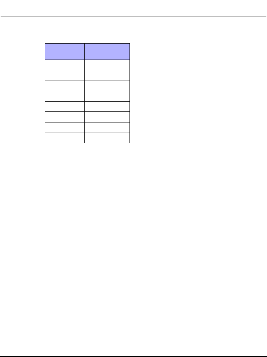
Operational, Basic, and Advanced Parameters
41-001160-03, Rev 00, Release 2.4 A-41
The following table identifies the default DSCP-to-priority mapping structure.
DSCP
Range DSCP Priority
0-7 0
8-15 1
16-23 2
24-31 3
32-39 4
40-47 5
48-55 6
56-63 7
Draft 1

Operational, Basic, and Advanced Parameters
A-42 41-001160-03, Rev 00, Release 2.4
IP Phone Administrator Guide
PC Port (Ethernet Port 1) Parameters
Parameter –
vlan id port 1
VLAN ID
(for PC Port in
Web UI)
IP phone UI Options->Administrator Menu->
Network Settings->VLAN->
Passthrough->VLAN ID
Aastra Web UI Advanced Settings->Network->VLAN->Port 1
Configuration Files aastra.cfg, <mac>.cfg
Description Specifies the VLAN ID used to pass packets through to a PC via Port 1.
Note: If you set the VLAN id port 1 (passthrough port) to 4095, all
untagged packets are sent to this port. The following is an example of
configuring the phone on a VLAN where all untagged packets are sent to
the passthrough port.
Example
You enable tagging on the phone port as normal but set the
passthrough port (VLAN id port 1) to 4095. The following example
sets the phone to be on VLAN 3 but the passthrough port is
configured as untagged.
tagging enabled: 1
VLAN id: 3
VLAN id port 1: 4095
Format Integer
Default Value 1
Range 1 to 4095
Example VLAN id port 1: 3
Draft 1

Operational, Basic, and Advanced Parameters
41-001160-03, Rev 00, Release 2.4 A-43
Parameter –
QoS eth port 1 priority
Priority
(for PC Port in
Web UI)
IP phone UI Options->Administrator Menu->
Network Settings->VLAN->Passthrough
->Priority
Aastra Web UI Advanced Settings->Network->VLAN->Port 1
Configuration Files aastra.cfg, <mac>.cfg
Description Specifies the priority value used for passing VLAN packets through to a
PC via Port 1.
Format Integer
Default Value 0
Range 0 to 7
Example QoS eth port 1 priority: 3
Draft 1

Operational, Basic, and Advanced Parameters
A-44 41-001160-03, Rev 00, Release 2.4
IP Phone Administrator Guide
Type of Service (ToS)/DSCP Settings
Parameter –
tos sip
SIP
(in Web UI)
IP phone UI Options->Administrator Menu->
Network Settings->Type of Service->SIP
Aastra Web UI Advanced Settings->Network->
Type of Service,DSCP
Configuration Files aastra.cfg, <mac>.cfg
Description The Differentiated Services Code Point (DSCP) for SIP packets.
Format Integer
Default Value 26
Range 0 to 63
Example tos sip: 3
Parameter –
tos rtp
RTP
(in Web UI)
IP phone UI Options->Administrator Menu->
Network Settings->Type of Service->RTP
Aastra Web UI Advanced Settings->Network->
Type of Service,DSCP
Configuration Files aastra.cfg, <mac>.cfg
Description The Differentiated Services Code Point (DSCP) for RTP packets.
Format Integer
Default Value 46
Range 0 to 63
Example tos rtp: 2
Parameter –
tos rtcp
RTCP
(in Web UI)
IP phone UI Options->Administrator Menu->
Network Settings->Type of Service->RTCP
Aastra Web UI Advanced Settings->Network->
Type of Service,DSCP
Configuration Files aastra.cfg, <mac>.cfg
Description The Differentiated Services Code Point (DSCP) for RTCP packets.
Format Integer
Default Value 46
Range 0 to 63
Example tos rtcp: 3
Draft 1

Operational, Basic, and Advanced Parameters
41-001160-03, Rev 00, Release 2.4 A-45
Time and Date Settings
Parameter –
time format
Time Format
(in Phone UI)
IP phone UI Options->Time and Date->Time Format
Configuration Files aastra.cfg, <mac>.cfg
Description This parameter changes the time to 12 hour or 24 hour format. Use “0”
for the 12 hour format and “1” for the 24 hour format.
Format Integer
Default Value 0
Range 0 (12 hr format))
1 (24 hr format)
Example time format: 0
Parameter –
date format
Date Format
(in Phone UI)
IP phone UI Options->Time and Date->Date Format
Configuration Files aastra.cfg, <mac>.cfg
Description This parameter allows the user to change the date to various formats.
Format Integer
Default Value 0
Range 0 (WWW MMM DD) (default)
1 (DD-MMM-YY)
2 (YYYY-MM-DD)
3 (DD/MM/YYYY)
4 (DD/MM/YY)
5 (DD-MM-YY)
6 (MM/DD/YY)
7 (MMM DD)
Example date format: 7
Draft 1

Operational, Basic, and Advanced Parameters
A-46 41-001160-03, Rev 00, Release 2.4
IP Phone Administrator Guide
Parameter –
dst config
Daylight Savings
(in Phone UI)
IP phone UI Options->Time and Date->Daylight Savings
Configuration Files aastra.cfg, <mac>.cfg
Description Enables/disables the use of daylight savings time.
Format Integer
Default Value 3
Range 0 - OFF
1 - 30 min summertime
2 - 1 hr summertime
3 - automatic
Example dst config: 0
Parameter –
time zone name
Time Zone
(in Phone UI)
IP phone UI Options->Time and Date->Time Zone
Configuration Files aastra.cfg, <mac>.cfg
Description Assigns a time zone name to the time server.
Format Text
Default Value US-Eastern
Range See “Time Zone Name/Time Zone Code Table” below.
Example time zone name: US-Central
Draft 1

Operational, Basic, and Advanced Parameters
41-001160-03, Rev 00, Release 2.4 A-47
Time Zone Name/Time Zone Code Table
Time Zone Name Time Zone Code
AD-Andorra
AE - United Arab Emirates (Dubai)
AG-Antigua
AI-Anguilla
AL-Tirane
AN-Curacao
AR-Buenos Aires
AS-Pago Pago
AT-Vienna
AU-Lord Howe
AU-Tasmania
AU-Melbourne
AU-Sydney
AU-Broken Hill
AU-Brisbane
AU-Lindeman
AU-Adelaide
AU-Darwin
AU-Perth
AW-Aruba
AZ - Azerbaijan (Baku)
CET
GST
AST
AST
CET
AST
ART
BST
CET
LHS
EST
EST
EST
CST
EST
EST
CST
CST
WST
AST
AZT
BA-Sarajevo
BB-Barbados
BE-Brussels
BG-Sofia
BM-Bermuda
BO-La Paz
BR-Noronha
BR-Belem
BR-Fortaleza
BR-Recife
BR-Araguaina
BR-Maceio
BR-Sao Paulo
BR-Cuiaba
BR-Porto Velho
BR-Boa Vista
BR-Manaus
BR-Eirunepe
BR-Rio Branco
BS-Nassau
BY-Minsk
BZ-Belize
EET
AST
CET
EET
AST
BOT
FNT
BRT
BRT
BRT
BRS
BRT
BRS
AMS
AMT
AMT
AMT
ACT
ACT
EST
EET
CST
Draft 1

Operational, Basic, and Advanced Parameters
A-48 41-001160-03, Rev 00, Release 2.4
IP Phone Administrator Guide
CA-Newfoundland
CA-Atlantic
CA-Eastern
CA-Saskatchewan
CA-Central
CA-Mountain
CA-Pacific
CA-Yukon
CH-Zurich
CK-Rarotonga
CL-Santiago
CL-Easter
CN-China
CO-Bogota
CR-Costa Rica
CU-Havana
CY-Nicosia
CZ-Prague
NST
AST
EST
EST
CST
MST
PST
PST
CET
CKS
CLS
EAS
CST
COS
CST
CST
EES
CET
DE-Berlin
DK-Copenhagen
DM-Dominica
DO-Santo Domingo
CET
CET
AST
AST
EE-Tallinn
ES-Madrid
ES-Canary
EET
CET
WET
FI-Helsinki
FJ-Fiji
FK-Stanley
FO-Faeroe
FR-Paris
EET
NZT
FKS
WET
CET
GB-London
GB-Belfast
GD-Grenada
GE - Georgia (Tbilisi)
GF-Cayenne
GI-Gibraltar
GP-Guadeloupe
GR-Athens
GS-South Georgia
GT-Guatemala
GU-Guam
GY-Guyana
GMT
GMT
AST
GET
GFT
CET
AST
EET
GST
CST
CST
GYT
Time Zone Name Time Zone Code
Draft 1

Operational, Basic, and Advanced Parameters
41-001160-03, Rev 00, Release 2.4 A-49
HK-Hong Kong
HN-Tegucigalpa
HR-Zagreb
HT-Port-au-Prince
HU-Budapest
HKS
CST
CET
EST
CET
IE-Dublin
IS-Reykjavik
IT-Rome
GMT
GMT
CET
JM-Jamaica
JP-Tokyo EST
JST
KY-Cayman EST
LC-St Lucia
LI-Vaduz
LT-Vilnius
LU-Luxembourg
LV-Riga
AST
CET
EET
CET
EET
MC-Monaco
MD-Chisinau
MK-Skopje
MQ-Martinique
MS-Montserrat
MT-Malta
MU - Mauritius
MX-Mexico City
MX-Cancun
MX-Merida
MX-Monterrey
MX-Mazatlan
MX-Chihuahua
MX-Hermosillo
MX-Tijuana
CET
EET
CET
AST
AST
CET
MUT
CST
CST
CST
CST
MST
MST
MST
PST
NI-Managua
NL-Amsterdam
NO-Oslo
NR-Nauru
NU-Niue
NZ-Auckland
NZ-Chatham
CST
CET
CET
NRT
NUT
NZS
CHA
OM - Oman (Muscat) GST
Time Zone Name Time Zone Code
Draft 1

Operational, Basic, and Advanced Parameters
A-50 41-001160-03, Rev 00, Release 2.4
IP Phone Administrator Guide
PA-Panama
PE-Lima
PL-Warsaw
PR-Puerto Rico
PT-Lisbon
PT-Madeira
PT-Azores
PY-Asuncion
EST
PES
CET
AST
WET
WET
AZO
PYS
RO-Bucharest
RU-Kaliningrad
RU-Moscow
RU-Samara
RU-Yekaterinburg
RU-Omsk
RU-Novosibirsk
RU-Krasnoyarsk
RU-Irkutsk
RU-Yakutsk
RU-Vladivostok
RU-Sakhalin
RU-Magadan
RU-Kamchatka
RU-Anadyr
EET
EET
MSK
SAM
YEK
OMS
NOV
KRA
IRK
YAK
VLA
SAK
MAG
PET
ANA
SE-Stockholm
SG-Singapore
SI-Ljubljana
SK-Bratislava
SM-San Marino
SR-Paramaribo
SV-El Salvador
CET
SGT
CET
CET
CET
SRT
CST
TR-Istanbul
TT-Port of Spain
TW-Taipei
EET
AST
CST
UA-Kiev
US-Eastern
US-Central
US-Mountain
US-Pacific
US-Alaska
US-Aleutian
US-Hawaii
UY-Montevideo
EET
EST
CST
MST
PST
AKS
HAS
HST
UYS
Time Zone Name Time Zone Code
Draft 1

Operational, Basic, and Advanced Parameters
41-001160-03, Rev 00, Release 2.4 A-51
VA-Vatican CET
YU-Belgrade CET
Time Zone Name Time Zone Code
Draft 1

Operational, Basic, and Advanced Parameters
A-52 41-001160-03, Rev 00, Release 2.4
IP Phone Administrator Guide
Time Server Settings
Parameter –
time server disabled
NTP Time Servers
(in Web UI)
Aastra Web UI Basic Settings->Preferences->
Time and Date Settings
IP Phone UI‘ Options->Preferences->
Time and Date->Time Servers
Configuration Files aastra.cfg, <mac>.cfg
Description Enables or disables the time server. This parameter affects the time
server1, time server2, and time server3 parameters. Setting this
parameter to 0 allows the use of the configured Time Server(s). Setting
this parameter to 1 prevents the use of the configured Time Server(s).
Note: For DHCP to automatically populate this parameter, your DHCP
server must support Option 66.
Format Integer
Default Value 0 (disabled)
Range 0 (disabled)
1 (enabled)
Example time server disabled: 0
Parameter –
time server1
Time Server 1
(in Web UI)
Aastra Web UI Basic Settings->Preferences->
Time and Date Settings
IP Phone UI‘ Options->Preferences->
Time and Date->Time Servers
Configuration Files aastra.cfg, <mac>.cfg
Description The primary time server's IP address or qualified domain name. If the
time server is enabled, the value for time server1 will be used to request
the time from.
Note: For DHCP to automatically populate this parameter, your DHCP
server must support Option 66.
Format IP address or qualified domain name
Default Value 0.0.0.0
Range Not Applicable
Example time server1: 192.168.0.5
Draft 1

Operational, Basic, and Advanced Parameters
41-001160-03, Rev 00, Release 2.4 A-53
Parameter –
time server2
Time Server 2
(in Web UI)
Aastra Web UI Basic Settings->Preferences->
Time and Date Settings
IP Phone UI‘ Options->Preferences->
Time and Date->Time Servers
Configuration Files aastra.cfg, <mac>.cfg
Description The secondary time server's IP address or qualified domain name. If the
time server is enabled, and the primary time server is not configured or
cannot be accessed the value for time server2 will be used to request
the time from.
Format IP address or qualified domain name
Default Value 0.0.0.0
Range Not Applicable
Example time server2: 192.168.0.5
Parameter –
time server3
Time Server 3
(in Web UI)
Aastra Web UI Basic Settings->Preferences->
Time and Date Settings
IP Phone UI‘ Options->Preferences->
Time and Date->Time Servers
Configuration Files aastra.cfg, <mac>.cfg
Description The tertiary time server's IP address or qualified domain name. If the
time server is enabled, and the primary and secondary time servers are
not configured or cannot be accessed the value for time server3 will be
used to request the time from.
Format IP address or qualified domain name
Default Value 0.0.0.0
Range Not Applicable
Example time server3: 192.168.0.5
Draft 1

Operational, Basic, and Advanced Parameters
A-54 41-001160-03, Rev 00, Release 2.4
IP Phone Administrator Guide
Custom Time Zone and DST Settings
Parameter –
time zone minutes Configuration Files aastra.cfg, <mac>.cfg
Description The number of minutes the timezone is offset from UTC (Coordinated
Universal Time). This can be positive (West of the Prime Meridian) or
negative (East of the Prim Meridian). Eastern Standard Time (EST) has
a value of 300.
Format Integer
Default Value N/A
Range Any positive or negative Integer
Example time zone minutes: 300
Parameter –
dst minutes Configuration Files aastra.cfg, <mac>.cfg
Description The number of minutes to add during Daylight Saving Time. Valid values
are a positive integer between 0 to 60.
Format Integer
Default Value N/A
Range 0 to 60
Example dst minutes: 60
Draft 1

Operational, Basic, and Advanced Parameters
41-001160-03, Rev 00, Release 2.4 A-55
Absolute Time
Parameter –
dst [start|end] relative date Configuration Files aastra.cfg, <mac>.cfg
Description Specifies how to interpret the start and end day, month, and week
parameters - absolute (0) or relative (1).
Format Boolean
Default Value N/A
Range 0 (absolute)
1 (relative)
Example dst [start|end] relative date: 1
Parameter –
dst start month Configuration Files aastra.cfg, <mac>.cfg
Description The month that DST starts. Valid values are 1 to 12 (January to
December).
Format Integer
Default Value N/A
Range 1 (January)
2 (February)
3 (March)
4 (April)
5 (May)
6 (June)
7 (July)
8 (August)
9 (September)
10 (October)
11 (November)
12 (December)
Example dst start month: 7
Draft 1

Operational, Basic, and Advanced Parameters
A-56 41-001160-03, Rev 00, Release 2.4
IP Phone Administrator Guide
Parameter –
dst end month Configuration Files aastra.cfg, <mac>.cfg
Description The month that DST ends. Valid values are 1 to 12 (January to
December).
Format Integer
Default Value N/A
Range 1 (January)
2 (February)
3 (March)
4 (April)
5 (May)
6 (June)
7 (July)
8 (August)
9 (September)
10 (October)
11 (November)
12 (December)
Example dst end month: 6
Draft 1

Operational, Basic, and Advanced Parameters
41-001160-03, Rev 00, Release 2.4 A-57
Parameter –
dst start day Configuration Files aastra.cfg, <mac>.cfg
Description The day of the month that DST starts. Valid values are 1 to 31.
Format Integer
Default Value N/A
Range 1 to 31
Example dst start day: 1
Parameter –
dst end day Configuration Files aastra.cfg, <mac>.cfg
Description The day of the month that DST ends. Valid values are 1 to 31.
Format Integer
Default Value N/A
Range 1 to 31
Example dst end day: 31
Parameter –
dst start hour Configuration Files aastra.cfg, <mac>.cfg
Description The hour that DST starts. Valid values are an integer from 0 (midnight)
to 23.
Format Integer
Default Value N/A
Range 0 (midnight) to 23
Example dst start hour: 0
Draft 1

Operational, Basic, and Advanced Parameters
A-58 41-001160-03, Rev 00, Release 2.4
IP Phone Administrator Guide
Relative Time
Parameter –
dst end hour Configuration Files aastra.cfg, <mac>.cfg
Description The hour that DST ends. Valid values are an integer from 0 (midnight) to
23.
Format Integer
Default Value N/A
Range 0 (midnight) to 23
Example dst end hour: 23
Parameter –
dst start month Configuration Files aastra.cfg, <mac>.cfg
Description The month that DST starts. Valid values are 1 to 12 (January to
December).
Format Integer
Default Value N/A
Range 1 (January)
2 (February)
3 (March)
4 (April)
5 (May)
6 (June)
7 (July)
8 (August)
9 (September)
10 (October)
11 (November)
12 (December)
Example dst start month: 6
Draft 1

Operational, Basic, and Advanced Parameters
41-001160-03, Rev 00, Release 2.4 A-59
Parameter –
dst end month Configuration Files aastra.cfg, <mac>.cfg
Description The month that DST ends. Valid values are 1 to 12 (January to
December).
Format Integer
Default Value N/A
Range 1 (January)
2 (February)
3 (March)
4 (April)
5 (May)
6 (June)
7 (July)
8 (August)
9 (September)
10 (October)
11 (November)
12 (December)
Example dst end month: 12
Draft 1

Operational, Basic, and Advanced Parameters
A-60 41-001160-03, Rev 00, Release 2.4
IP Phone Administrator Guide
Parameter –
dst start week Configuration Files aastra.cfg, <mac>.cfg
Description The week in the specified month in which DST starts. Valid value is a
positive or negative integer from 1 to 5.
Format Integer
Default Value N/A
Range 1 = first full week of month
-1 = last full week of month
2 = second full week of month
-2 = last full week of month
3 = third full week of month
-3 = last full week of month
4 = fourth full week of month
-4 = last full week of month
5 = fifth full week of month
-5 = last full week of month
Example dst start week: 1
Parameter –
dst end week Configuration Files aastra.cfg, <mac>.cfg
Description The week in the specified month in which DST ends. Valid value is a
positive or negative integer from 1 to 5.
Format Integer
Default Value N/A
Range 1 = first full week of month
-1 = last full week of month
2 = second full week of month
-2 = last full week of month
3 = third full week of month
-3 = last full week of month
4 = fourth full week of month
-4 = last full week of month
5 = fifth full week of month
-5 = last full week of month
Example dst end week: 5
Draft 1

Operational, Basic, and Advanced Parameters
41-001160-03, Rev 00, Release 2.4 A-61
Parameter –
dst start day Configuration Files aastra.cfg, <mac>.cfg
Description The day of the specified week in the specified month that DST starts on.
Valid values are an integer from 1 to 7.
Format Integer
Default Value N/A
Range 1 (Sunday)
2 (Monday)
3 (Tuesday)
4 (Wednesday)
5 (Thursday)
6 (Friday)
7 (Saturday)
Example dst start day: 1
Parameter –
dst end day Configuration Files aastra.cfg, <mac>.cfg
Description The day of the specified week in the specified month that DST ends on.
Valid values are an integer from 1 to 7.
Format Integer
Default Value N/A
Range 1 (Sunday)
2 (Monday)
3 (Tuesday)
4 (Wednesday)
5 (Thursday)
6 (Friday)
7 (Saturday)
Example dst end day: 7
Draft 1

Operational, Basic, and Advanced Parameters
A-62 41-001160-03, Rev 00, Release 2.4
IP Phone Administrator Guide
Parameter –
dst start hour Configuration Files aastra.cfg, <mac>.cfg
Description The hour that DST starts. Valid values are an integer from 0 (midnight)
to 23.
Format Integer
Default Value N/A
Range 0 (midnight) to 23
Example dst start hour: 0
Parameter –
dst end hour Configuration Files aastra.cfg, <mac>.cfg
Description The hour that DST ends. Valid values are an integer from 0 (midnight) to
23.
Format Integer
Default Value N/A
Range 0 (midnight) to 23
Example dst end hour: 23
Draft 1

Operational, Basic, and Advanced Parameters
41-001160-03, Rev 00, Release 2.4 A-63
Backlight Mode Settings (9480i, 9480i CT, 6755i, 6757i, 6757i CT)
Parameter –
backlight mode
Backlight
(in Phone UI)
IP phone UI Options->Preferences->Display->Backlight
Configuration Files aastra.cfg, <mac>.cfg
Description Allows you to turn the backlight on the LCD, On, Off, or Auto. “The Auto”
setting sets the phone to turn off the backlighting after a period of
inactivity.
Format Integer
Default Value 1 (Auto)
Range 0 (Off - Turns the backlight off constant)
1(Auto - Turns the backlight off after a period of inactivity.)
Example backlight mode: 0
Parameter –
bl on time
Backllight On Time
(in Phone UI)
IP phone UI Options->Preferences->Display->Backlight
Configuration Files aastra.cfg, <mac>.cfg
Description Allows you to set the amount of time, in seconds, that the backlight
stays ON before turning OFF because of inactivity. This settings is
applicable to the “Auto” mode only.
Format Integer
Default Value 10
Range 1 to 120 minutes (2 hours)
Example bl on timer: 15
Draft 1

Operational, Basic, and Advanced Parameters
A-64 41-001160-03, Rev 00, Release 2.4
IP Phone Administrator Guide
Live Dialpad Settings
Parameter –
live dialpad
Live Dialpad
(in Phone UI)
IP phone UI Options->Preferences->Live Dialpad
Configuration Files aastra.cfg, <mac>.cfg
Description Turns the “Live Dialpad” feature ON or OFF.
With live dial pad ON, the IP phone automatically dials out and turns ON
Handsfree mode as soon as a dial pad key or softkey is pressed. With
live dial pad OFF, if you dial a number while the phone is on-hook, lifting
the receiver or pressing the initiates a call to that number.
Format Boolean
Default Value 0 (Off)
Range 0 (Off)
1 (On)
Example live dialpad: 1
Draft 1

Operational, Basic, and Advanced Parameters
41-001160-03, Rev 00, Release 2.4 A-65
SIP Local Dial Plan Settings
Parameter –
sip dial plan
Local Dial Plan
(in Web UI)
Aastra Web UI Basic Settings->Preferences
Configuration Files aastra.cfg, <mac>.cfg
Description A dial plan describes the number and pattern of digits that a user dials to
reach a particular telephone number. The SIP local dial plan is as follows:
Symbol Description
0, 1, 2, 3, 4, 5, 6, 7, 8, 9 Digit symbol
X Match any digit symbol (wildcard)
*, #, . Other keypad symbol; # can terminate
a dial string
| Expression inclusive OR
+ 0 or more of the preceding digit symbol
or [] expression
[] Symbol inclusive OR
- Used only with [], represent a range of
acceptable symbols; For example, [2-8]
“,” (open/close quotes) In the configuration files, enter the sip dial
plan value using quotes.
.;. Used when a secondary dial tone is
required on the phone. (For example,
“9;xxxxxx”, when a user has to dial “9” to get
and outside line and needs a secondary dial
tone presented.
Note: You can configure prefix dialing by adding a prepend digit to the
dial string. For example, if you add a prepend map of
“[2-9]XXXXXXXXX,91”, the IP phone adds the digits “91” to any 10-digit
number beginning with any digit from 2 to 9 that is dialed out. Other
examples of prepend mappings are:
•1X+#,9 (Prepends 9 to any digit string beginning with “1” and
terminating with “#”.)
•6XXX,579 (Prepends “579” to any 4-digit string starting with “6”.)
•[4-6]XXXXXX,78 (Prepends “78” to any 7-digit string starting with “4”,
“5”, or “6”.
Format Alphanumeric characters
Default Value X+#|XX+*
Range Up to 512 alphanumeric characters.
Note: If a User enters a dial plan longer than 512 characters, or a parsing
error occurs, the phone uses the default dial plan of “x+#|xx+*”. If this is
the case, the Administrator cannot change the dial plan from the
configuration files. The dial plan must be changed from the Aastra Web
UI.
Example sip dial plan: "X+#|XXX+*"
Draft 1

Operational, Basic, and Advanced Parameters
A-66 41-001160-03, Rev 00, Release 2.4
IP Phone Administrator Guide
Parameter –
sip dial plan terminator
Send Dial Plan Terminator
(in Web UI)
Aastra Web UI Basic Settings->Preferences
Configuration Files aastra.cfg, <mac>.cfg
Description Allows you to enable or disable a dial plan terminator. If you enable the
use of this parameter, when you configure the IP phone’s dial plan with a
dial plan terminator or timeout (such as the pound symbol (#)), the phone
waits 4 or 5 seconds after you pick up the handset or after to finish
dialing the number on the keypad before making the call.
Format Boolean
Default Value 0
Range 0 (Disable)
1 (Enable)
Example sip dial plan terminator: 1
Parameter –
sip digit timeout
Digit Timeout
(in Web UI)
Aastra Web UI Basic Settings->Preferences
Configuration Files aastra.cfg, <mac>.cfg
Description Represents the time, in seconds, between consecutive key presses on
the IP phone. The default for this parameter is 4 seconds. If you press a
key on the phone and wait 4 seconds before pressing the next key, the
key times out and cancels the digit selection. You must press consecutive
keys before the timeout occurs.
Format Integer
Default Value 4
Range Not Applicable
Example sip digit timeout: 6
Draft 1

Operational, Basic, and Advanced Parameters
41-001160-03, Rev 00, Release 2.4 A-67
SIP Basic, Global Settings
SIP Global Authentication Settings
Parameter –
sip screen name
Screen Name
(in Web UI)
IP Phone UI Options->Administrator Menu->SIP Settings
Aastra Web UI Advanced Settings->Global SIP->
Basic SIP Settings
Configuration Files aastra.cfg, <mac>.cfg
Description Used to display text on the screen of the phone. You may want to set
this parameter to display the user’s name of the phone.
Format Text
Default Value Not Applicable
Range Up to 20 alphanumeric characters
Example sip screen name: Joe Smith
Parameter –
sip screen name 2
Screen Name 2
(in Web UI)
IP Phone UI Options->Administrator Menu->SIP Settings
Aastra Web UI Advanced Settings->Global SIP->
Basic SIP Settings
Configuration Files aastra.cfg, <mac>.cfg
Description Used to display text on a second line on the screen of the phone.
Notes:
1. If other status messages display on the phone, such as “Network
Disconnected”, the Screen Name 2 value does not display.
2. Symbol characters are allowed (such as “#”).
3. If the text is longer than the display width, than the display truncates
the text to fit the display.
Format Alphanumeric characters.
Default Value Not Applicable
Range Up to 20 alphanumeric characters.
Example sip screen name 2: Lab Phone
Draft 1

Operational, Basic, and Advanced Parameters
A-68 41-001160-03, Rev 00, Release 2.4
IP Phone Administrator Guide
Parameter –
sip user name
Phone Number
(in Web UI)
IP Phone UI Options->Administrator Menu->SIP Settings
Aastra Web UI Advanced Settings->Global SIP->
Basic SIP Settings
Configuration Files aastra.cfg, <mac>.cfg
Description Used in the name field of the SIP URI for the IP phone and for registering
the IP phone at the registrar.
Note: The IP Phones support Usernames containing dots (“.”).
Format Text
Default Value Not Applicable
Range Up to 20 alphanumeric characters
Example sip user name: 1010
Parameter –
sip display name
Caller ID
(in Web UI)
IP Phone UI Options->Administrator Menu->SIP Settings
Aastra Web UI Advanced Settings->Global SIP->
Basic SIP Settings
Configuration Files aastra.cfg, <mac>.cfg
Description Used in the display name field of the From SIP header field. Some IP
PBX systems use this as the caller’s ID and some may overwrite this
with the string that is set at the PBX system.
Format Text
Default Value Not Applicable
Range Up to 20 alphanumeric characters
Example sip display name: Joe Smith
Draft 1

Operational, Basic, and Advanced Parameters
41-001160-03, Rev 00, Release 2.4 A-69
Parameter –
sip auth name
Authentication Name
(in Web UI)
IP Phone UI Options->Administrator Menu->>SIP Settings
Aastra Web UI Advanced Settings->Global SIP->
Basic SIP Settings
Configuration Files aastra.cfg, <mac>.cfg
Description Used in the username field of the Authorization header field of the SIP
REGISTER request.
Format Text
Default Value Not Applicable
Range Up to 20 alphanumeric characters
Example sip auth name: 5553456
Parameter –
sip password
Password
(in Web UI)
IP Phone UI Options->Administrator Menu->SIP Settings
Aastra Web UI Advanced Settings->Global SIP->
Basic SIP Settings
Configuration Files aastra.cfg, <mac>.cfg
Description The password that will be used to register at the registrar.
Format Text
Default Value Not Applicable
Range Up to 20 alphanumeric characters
Example sip password: 12345
Draft 1

Operational, Basic, and Advanced Parameters
A-70 41-001160-03, Rev 00, Release 2.4
IP Phone Administrator Guide
Parameter –
sip bla number
BLA Number
(in Web UI)
Aastra Web UI Advanced Settings->Global SIP->
Basic SIP Settings
Configuration Files aastra.cfg, <mac>.cfg
Description Allows you to assign a phone number that is shared across all IP
phones.
Format Integer
Default Value Not Applicable
Range Not Applicable
Example sip bla number: 1010
Parameter –
sip mode
Line mode
(in Web UI)
Aastra Web UI Advanced Settings->Global SIP->
Basic SIP Settings
Configuration Files aastra.cfg, <mac>.cfg
Description Allows you to configure the mode of the line. Applicable values are:
•Generic - Normal line
•BroadSoft SCA - Shared Call/Line Appearances (SCA) line for
BroadWorks network (call activity can go to more than one phone)
•Nortel - Conference line for Nortel Networks (private - all call activity
goes to one phone)
•BLA - Bridged Line Appearance (BLA) line.
Format Integer
Default Value 0
Range Valid values are:
0 - Generic
1 - BroadSoft SCA
2 - Nortel
3 - BLA
Example sip mode: 2
Draft 1

Operational, Basic, and Advanced Parameters
41-001160-03, Rev 00, Release 2.4 A-71
SIP Global Network Settings.
Parameter –
sip proxy ip
Proxy Server
(in Web UI)
IP Phone UI Options->Administrator Menu->SIP Settings
Aastra Web UI Advanced Settings->Global SIP->
Basic SIP Settings
Configuration Files aastra.cfg, <mac>.cfg
Description The IP address of the SIP proxy server for which the IP phone uses to
send all SIP requests.
A SIP proxy is a server that initiates and forwards requests generated by
the IP phone to the targeted user.
Format IP address or fully qualified Domain Name
Default Value 0.0.0.0
Range Not applicable
Example sip proxy ip: 192.168.0.101
Parameter –
sip proxy port
Proxy Port
(in Web UI)
IP Phone UI Options->Administrator Menu->SIP Settings
Aastra Web UI Advanced Settings->Global SIP->
Basic SIP Settings
Configuration Files aastra.cfg, <mac>.cfg
Description The proxy server's port number.
Format Integer
Default Value 0
Range Not Applicable
Example sip proxy port: 5060
Draft 1

Operational, Basic, and Advanced Parameters
A-72 41-001160-03, Rev 00, Release 2.4
IP Phone Administrator Guide
Parameter –
sip backup proxy ip
Backup Proxy Server
(in Web UI)
Aastra Web UI Advanced Settings->Global SIP->
Basic SIP Network Settings
Configuration Files aastra.cfg, <mac>.cfg
Description The IP address of the backup SIP proxy server for which the IP phone
uses when the primary SIP proxy is unavailable.
Format IP address or fully qualified Domain Name
Default Value 0.0.0.0
Range Not Applicable
Example sip backup proxy ip: 192.168.0.102
Parameter –
sip backup proxy port
Backup Proxy Port
(in Web UI)
Aastra Web UI Advanced Settings->Global SIP->
Basic SIP Network Settings
Configuration Files aastra.cfg, <mac>.cfg
Description The backup proxy’s port number.
Format Integer
Default Value 0
Range Not Applicable
Example sip backup proxy port: 5060
Parameter –
sip outbound proxy
outbound proxy server
(in Web UI)
Aastra Web UI Advanced Settings->Global SIP->
Advanced SIP Settings
Configuration Files aastra.cfg, <mac>.cfg
Description This is the address of the outbound proxy server. All SIP messages
originating from the phone are sent to this server. For example, if you
have a Session Border Controller in your network, then you would
normally set its address here.
Format IP Address or fully qualified Domain Name
Default Value 0.0.0.0
Range Not Applicable
Example sip outbound proxy: 10.42.23.13
Draft 1

Operational, Basic, and Advanced Parameters
41-001160-03, Rev 00, Release 2.4 A-73
Parameter –
sip outbound proxy port
outbound proxy port
(in Web UI)
Aastra Web UI Advanced Settings->Global SIP->
Advanced SIP Settings
Configuration Files aastra.cfg, <mac>.cfg
Description The proxy port on the proxy server to which the IP phone sends all SIP
messages.
Format Integer
Default Value 0
Range Not Applicable
Example sip outbound proxy port: 5060
Parameter –
sip registrar ip
Registrar Server
(in Web UI)
IP Phone UI Options->Administrator Menu->SIP Settings
Aastra Web UI Advanced Settings->Global SIP->
Basic SIP Settings
Configuration Files aastra.cfg, <mac>.cfg
Description The address of the registrar for which the IP phone uses to send
REGISTER requests.
A SIP registrar is a server that maintains the location information of the
IP phone.
A global value of 0.0.0.0 disables registration. However, the phone is still
active and you can dial using username@ip address of the phone.
If the Registrar IP address is set to 0.0.0.0 for a per-line basis (i.e, line 1,
line 2, etc.), then the register request is not sent, the "No Service"
message does not display, and the message waiting indicator (MWI)
does not come on.
Format IP address or fully qualified Domain Name
Default Value 0.0.0.0
Range Not Applicable
Example sip registrar ip: 192.168.0.101
Draft 1

Operational, Basic, and Advanced Parameters
A-74 41-001160-03, Rev 00, Release 2.4
IP Phone Administrator Guide
Parameter –
sip registrar port
Registrar Port
(in Web UI)
IP Phone UI Options->Administrator Menu->SIP Settings
Aastra Web UI Advanced Settings->Global SIP->
Basic SIP Settings
Configuration Files aastra.cfg, <mac>.cfg
Description The registrar's port number.
Format Integer
Default Value 0
Range Not Applicable
Example sip registrar port: 5060
Parameter –
sip backup registrar ip
Backup Registrar Server
(in Web UI)
Aastra Web UI Advanced Settings->Global SIP->
Basic SIP Network Settings
Configuration Files aastra.cfg, <mac>.cfg
Description The address of the backup registrar (typically, the backup SIP proxy) for
which the IP phone uses to send REGISTER requests if the primary
registrar is unavailable.
A global value of 0.0.0.0 disables backup registration. However, the
phone is still active and you can dial using username@ip address of the
phone.
If the backup registrar IP address is set to 0.0.0.0 for a per-line basis (i.e,
line 1, line 2, etc.), then the backup register request is not sent, the "No
Service" message does not display, and the message waiting indicator
(MWI) does not come on.
Format IP address or fully qualified Domain Name
Default Value 0.0.0.0
Range Not Applicable
Example sip backup registrar ip: 192.168.0.102
Draft 1

Operational, Basic, and Advanced Parameters
41-001160-03, Rev 00, Release 2.4 A-75
Parameter –
sip backup registrar port
Backup Registrar Port
(in Web UI)
Aastra Web UI Advanced Settings->Global SIP->
Basic SIP Network Settings
Configuration Files aastra.cfg, <mac>.cfg
Description The backup registrar's (typically the backup SIP proxy) port number.
Format Integer
Default Value 0
Range Not Applicable
Example sip backup registrar port: 5060
Parameter –
sip registration period
Registration Period
(in Web UI)
Aastra Web UI Advanced Settings->Global SIP->
Basic SIP Network Settings
Configuration Files aastra.cfg, <mac>.cfg
Description The requested registration period, in seconds, from the registrar.
Format Integer
Default Value 0
Range 0 to 2147483647
Example sip registration period: 3600
Draft 1

Operational, Basic, and Advanced Parameters
A-76 41-001160-03, Rev 00, Release 2.4
IP Phone Administrator Guide
SIP Basic, Per-Line Settings
The following parameters are SIP per-line settings. The value of "N" is 1 - 9 for
9143i, 9480i, 9480i CT, 6753i, 6755i, 6757i, and 6757i CT.
SIP Per-Line Authentication Settings
Parameter –
sip lineN screen name
Screen Name
(in Web UI)
Aastra Web UI Advanced Settings->Line 1 thru 9
Configuration Files aastra.cfg, <mac>.cfg
Description Used to display text on the screen of the phone. You may want to set
this parameter to display the phone user's name.
Format Text
Default Value Not Applicable
Range Up to 20 alphanumeric characters
Example sip line1 screen name: Joe Smith
Parameter –
sip lineN screen name 2
Screen Name 2
(in Web UI)
Aastra Web UI Advanced Settings->Line 1 thru 9
Configuration Files aastra.cfg, <mac>.cfg
Description Used to display text on a second line on the screen of the phone.
Notes:
1. If other status messages display on the phone, such as “Network
Disconnected”, the Screen Name 2 value does not display.
2. Characters are allowed (such as “#”).
3. If the text is longer than the display width, than the display truncates
the text to fit the display.
Format Alphanumeric characters
Default Value Not Applicable
Range Up to 20 alphanumeric characters
Example sip line1 screen name 2: Lab Phone
Draft 1

Operational, Basic, and Advanced Parameters
41-001160-03, Rev 00, Release 2.4 A-77
Parameter –
sip lineN user name
Phone Number
(in Web UI)
Aastra Web UI Advanced Settings->Line 1 thru 9
Configuration Files aastra.cfg, <mac>.cfg
Description Used in the name field of the SIP URI for the IP phone and for registering
the IP phone at the registrar.
When configuring per-line BLA on an ININ server, the username must be
incremented as shown in the example for the "sip lineN bla number"
parameter on page A-79.
Note: The IP Phones support Usernames containing dots (“.”).
Format Text
Default Value Not Applicable
Range Up to 20 alphanumeric characters
Example sip line1 user name: 1010
Parameter –
sip lineN display name
Caller ID
(in Web UI)
Aastra Web UI Advanced Settings->Line 1 thru 9
Configuration Files aastra.cfg, <mac>.cfg
Description Used in the display name field of the From SIP header field. Some IP
PBX systems use this as the caller’s ID and some may overwrite this
with the string that is set at the PBX system.
Format Text
Default Value Not Applicable
Range Up to 20 alphanumeric characters
Example sip line1 display name: Joe Smith
Draft 1

Operational, Basic, and Advanced Parameters
A-78 41-001160-03, Rev 00, Release 2.4
IP Phone Administrator Guide
Parameter –
sip lineN auth name
Authentication Name
(in Web UI)
Aastra Web UI Advanced Settings->Line 1 thru 9
Configuration Files aastra.cfg, <mac>.cfg
Description Used in the username field of the Authorization header field of the SIP
REGISTER request.
Format Text
Default Value Not Applicable
Range Up to 20 alphanumeric characters
Example sip line1 auth name: 5553456
Parameter –
sip lineN password
Password
(in Web UI)
Aastra Web UI Advanced Settings->Line 1 thru 9
Configuration Files aastra.cfg, <mac>.cfg
Description The password that will be used to register at the registrar.
Format Text
Default Value Not Applicable
Range Up to 20 alphanumeric characters
Example sip line1 password: 12345
Draft 1

Operational, Basic, and Advanced Parameters
41-001160-03, Rev 00, Release 2.4 A-79
Parameter –
sip lineN bla number
BLA Number
(in Web UI)
Aastra Web UI Advanced Settings->Line 1 thru 9
Configuration Files aastra.cfg, <mac>.cfg
Description Allows you to assign a phone number that is shared on specific lines on
the IP phone.
For Sylantro Server:
When configuring the BLA feature on a Sylantro server, the value set for
the sip lineN bla number parameter shall be the same value set for the
sip lineN user name parameter for all the phones in the group. For
example, if sip lineN user name is 1010, you would configure BLA on a
per-line basis for the Sylantro server as follows:
sip line1 user name: 1010(# for all the phones)
sip line1 bla number: 1010
For ININ Server:
When configuring the BLA feature on an ININ server, the value set for the
sip lineN bla number parameter shall be the same value set for the sip
lineN user name parameter without the incremented digit added to the
phone #. For example, if the sip lineN user name for the first phone is
10101, and the sip lineN user name for the second phone is 10102, etc.
you would configure BLA on a per-line basis for the ININ server as
follows:
sip line1 user name: 10101(# for phone 1 with)
sip line1 bla number: 1010appearance of phone 3)
sip line1 user name: 10102(# for phone 2 with)
sip line1 bla number: 1010appearance of phone 3)
sip line1 user name: 1010(# for phone 3)
sip line1 bla number: 1010
Note: The original phone number which has the bridged line appearance
on other phones, will have the "sip lineN user name" parameter the same
as the "sip lineN bla number" (1010 in the above example on Phone 3).
Format Integer
Default Value Not Applicable
Range Not Applicable
Example Sylantro Server:
sip line1 bla number: 1010
ININ Server:
sip line 1 bla number: 1010
Draft 1

Operational, Basic, and Advanced Parameters
A-80 41-001160-03, Rev 00, Release 2.4
IP Phone Administrator Guide
Parameter –
sip lineN mode
Line Mode
(in Web UI)
Aastra Web UI Advanced Settings->Line 1 thru 9
Configuration Files aastra.cfg, <mac>.cfg
Description Allows you to configure the mode of the line. Applicable values are:
•Generic - Normal line
•BroadSoft SCA - Shared Call/Line Appearances (SCA) line for
BroadWorks network (call activity can go to more than one phone)
•Nortel - Conference line for Nortel Networks (private - all call activity
goes to one phone)
•BLA - Bridged Line Appearance (BLA) line.
• If the softkeys on the 6757i/6757i CT or the programmable keys on
the 6753i are set as line keys, and you configure that line key for
BLA, the key is configured to use BLA.
Format Integer
Default Value 0
Range Valid values are:
0 - Generic
1 - BroadSoft SCA
2 - Nortel
3 - BLA
Example sip line1 mode: 2
Draft 1

Operational, Basic, and Advanced Parameters
41-001160-03, Rev 00, Release 2.4 A-81
SIP Per-Line Network Settings.
Parameter –
sip lineN proxy ip
Proxy Server
(in Web UI)
Aastra Web UI Advanced Settings->Line 1 thru 9
Configuration Files aastra.cfg, <mac>.cfg
Description The IP address of the SIP proxy server for which the IP phone uses to
send all SIP requests.
A SIP proxy is a server that initiates and forwards requests generated by
the IP phone to the targeted user.
Format IP address or fully qualified Domain Name
Default Value 0.0.0.0
Range Not applicable
Example sip line1 proxy ip: 192.168.0.101
Parameter –
sip lineN proxy port
Proxy Port
(in Web UI)
Aastra Web UI Advanced Settings->Line 1 thru 9
Configuration Files aastra.cfg, <mac>.cfg
Description The proxy server's port number
Format Integer
Default Value 0
Range Not Applicable
Example sip line1 proxy port: 5060
Draft 1

Operational, Basic, and Advanced Parameters
A-82 41-001160-03, Rev 00, Release 2.4
IP Phone Administrator Guide
Parameter –
sip linex backup proxy ip
Backup Proxy Server
(in Web UI)
Aastra Web UI Advanced Settings->Line 1 thru 9
Configuration Files aastra.cfg, <mac>.cfg
Description The IP address of the backup SIP proxy server for which the IP phone
uses when the primary SIP proxy is unavailable.
Format IP address or fully qualified Domain Name
Default Value 0.0.0.0
Range Not Applicable
Example sip line1 backup proxy ip: 192.168.0.102
Parameter –
sip linex backup proxy port
Backup Proxy Port
(in Web UI)
Aastra Web UI Advanced Settings->Line 1 thru 9
Configuration Files aastra.cfg, <mac>.cfg
Description The backup proxy’s port number.
Format Integer
Default Value 0
Range Not Applicable
Example sip line1 backup proxy port: 5060
Draft 1

Operational, Basic, and Advanced Parameters
41-001160-03, Rev 00, Release 2.4 A-83
Parameter –
sip lineN outbound proxy
Outbound Proxy Server
(in Web UI)
Aastra Web UI Advanced Settings->Line 1 thru 9
Configuration Files aastra.cfg, <mac>.cfg
Description This is the address of the outbound proxy server. All SIP messages
originating from the phone are sent to this server. For example, if you
have a Session Border Controller in your network, then you would
normally set its address here.
Format IP Address or fully qualified Domain Name
Default Value 0.0.0.0
Range Not Applicable
Example sip outbound proxy: 10.42.23.13
Parameter –
sip lineN outbound proxy port
Outbound Proxy Port
(in Web UI)
Aastra Web UI Advanced Settings->Line 1 thru 9
Configuration Files aastra.cfg, <mac>.cfg
Description The proxy port on the proxy server to which the IP phone sends all SIP
messages.
Format Integer
Default Value 0
Range Not Applicable
Example sip outbound proxy port: 5060
Draft 1

Operational, Basic, and Advanced Parameters
A-84 41-001160-03, Rev 00, Release 2.4
IP Phone Administrator Guide
Parameter –
sip lineN registrar ip
Registrar Server
(in Web UI)
Aastra Web UI Advanced Settings->Line 1 thru 9
Configuration Files aastra.cfg, <mac>.cfg
Description The address of the registrar for which the IP phone uses to send
REGISTER requests.
A SIP registrar is a server that maintains the location information of the
IP phone.
A global value of 0.0.0.0 disables registration. However, the phone is still
active and you can dial using username@ip address of the phone.
If the Registrar IP address is set to 0.0.0.0 for a per-line basis (i.e, line 1,
line 2, etc.), then the register request is not sent, the "No Service"
message does not display, and the message waiting indicator (MWI)
does not come on.
Format IP address or fully qualified Domain Name
Default Value 0.0.0.0
Range Not Applicable
Example sip line1 registrar ip: 192.168.0.101
Draft 1

Operational, Basic, and Advanced Parameters
41-001160-03, Rev 00, Release 2.4 A-85
Parameter –
sip lineN registrar port
Registrar Port
(in Web UI)
Aastra Web UI Advanced Settings->Line 1 thru 9
Configuration Files aastra.cfg, <mac>.cfg
Description The registrar's port number
Format Integer
Default Value 0
Range Not Applicable
Example sip line1 registrar port: 5060
Parameter –
sip linex backup registrar ip
Backup Registrar Server
(in Web UI)
Aastra Web UI Advanced Settings->LineN->
Basic SIP Network Settings
Configuration Files aastra.cfg, <mac>.cfg
Description The address of the backup registrar (typically, the backup SIP proxy) for
which the IP phone uses to send REGISTER requests if the primary
registrar is unavailable.
A global value of 0.0.0.0 disables backup registration. However, the
phone is still active and you can dial using username@ip address of the
phone.
If the backup registrar IP address is set to 0.0.0.0 for a per-line basis (i.e,
line 1, line 2, etc.), then the backup register request is not sent, the "No
Service" message does not display, and the message waiting indicator
(MWI) does not come on.
Format IP address or fully qualified Domain Name
Default Value 0.0.0.0
Range Not Applicable
Example sip line1 backup registrar ip: 192.168.0.102
Draft 1

Operational, Basic, and Advanced Parameters
A-86 41-001160-03, Rev 00, Release 2.4
IP Phone Administrator Guide
Parameter –
sip linex backup registrar port
Backup Registrar Port
(in Web UI)
Aastra Web UI Advanced Settings->LineN->
Basic SIP Network Settings
Configuration Files aastra.cfg, <mac>.cfg
Description The backup registrar's (typically the backup SIP proxy) port number.
Format Integer
Default Value 0
Range Not Applicable
Example sip line1 backup registrar port: 5060
Parameter –
sip lineN registration period
Registration Period
(in Web UI)
Aastra Web UI Advanced Settings->Line 1 thru 9
Configuration Files aastra.cfg, <mac>.cfg
Description The requested registration period, in seconds, from the registrar.
Format Integer
Default Value 0
Range 0 to 2147483647
Example sip line1 registration period: 3600
Draft 1

Operational, Basic, and Advanced Parameters
41-001160-03, Rev 00, Release 2.4 A-87
BLA Support for MWI
Parameter –
sip mwi for bla account
MWI for BLA Account
(in Web UI)
Configuration Files aastra.cfg, <mac>.cfg
Aastra Web UI Advanced Settings->Global SIP->
Advanced SIP Settings
Description Enables or disables a BLA configured line to send an MWI SUBSCRIBE
message for the BLA account.
Notes:
1. If you change the setting on this parameter, you must reboot the
phone for it to take affect.
2. Both the “sip explicit mwi subscription” and “sip mwi for bla
account” parameters must be enabled in order for the MWI subscription
for BLA to occur.
3. The MWI re-subscription for the BLA account uses the value set for
the "sip explicit mwi subscription period" parameter to re-subscribe.
4. Whether or not the "sip mwi for bla account" parameter is enabled,
the priority for displaying MWI does not change.
Format Boolean
Default Value 0 (disabled)
Range 0 (disabled)
1 (enabled)
Example sip mwi for bla account: 1
Draft 1

Operational, Basic, and Advanced Parameters
A-88 41-001160-03, Rev 00, Release 2.4
IP Phone Administrator Guide
Centralized Conferencing Settings
Global Settings
Parameter –
sip centralized conf
Conference Server URI
(in Web UI)
Aastra Web UI Advanced->Global SIP Settings->
Basic SIP Network Settings
Configuration Files aastra.cfg, <mac>.cfg
Description Globally enables or disables SIP centralized conferencing for an IP
phone as follows:
• To disable centralized conferencing, leave this field empty (blank).
• To enable SIP centralized conferencing, then do one of the following
actions:
—If you have specified a proxy server/registrar server, then to
reach the media server via the proxy server, set this field to
one of the following:
conf (Sylantro server), or
Conference (Broadsoft server)
By setting this field to conf, you specify conf@<proxy_server
_address>: <proxy_port>. For example, if the proxy server address is
206.229.26.60 and the proxy port used is 10060, then by setting this
parameter to conf, you are specifying the following:
conf@206.229.26.60:10060
— To reach the media server using a different address/port than
that specified by the proxy, set this field to the following:
conf@<media_server _address>: <media_port>
Format String
Default Value Blank
Example sip centralized conf: conf
Draft 1

Operational, Basic, and Advanced Parameters
41-001160-03, Rev 00, Release 2.4 A-89
Per-Line Settings
Parameter –
sip lineN centralized conf
Conference Server URI
(in Web UI)
Aastra Web UI Advanced->Line <1 thru 9>->
Basic SIP Network Settings
Configuration Files aastra.cfg, <mac>.cfg
Description Enable or disable per-line SIP centralized conferencing for an IP phone
as follows:
• To disable centralized conferencing, leave this field empty (blank).
• To enable SIP centralized conferencing on a specific line, do one of
the following actions:
— If you have specified a proxy server/registrar server, then to
reach the media server via the proxy server, set this field to
one of the following:
conf (Sylantro server), or
Conference (Broadsoft server)
By setting this field to conf, you specify conf@<proxy_server
_address>: <proxy_port>. For example, if the proxy server address
is 206.229.26.60 and the proxy port used is 10060, then by setting
this parameter to conf, you are specifying the following:
conf@206.229.26.60:10060.
— To reach the media server using a different address/port than
that specified by the proxy, set this field to the following:
conf@<media_server _address>: <media_port>
Format String
Default Value Blank
Examples sip line3 centralized conf: conf
Draft 1

Operational, Basic, and Advanced Parameters
A-90 41-001160-03, Rev 00, Release 2.4
IP Phone Administrator Guide
SIP Join Feature for 3-Way Conference
Parameter –
sip join support Configuration Files aastra.cfg, <mac>.cfg
Description Enables or disables the phone to allow a conference to be set up with a
join header as described in RFC 3911.
Format Boolean
Default Value 0 (disabled)
Range 0 (disabled)
1 (enabled)
Example sip join support: 1
Draft 1

Operational, Basic, and Advanced Parameters
41-001160-03, Rev 00, Release 2.4 A-91
HTTP/HTTPS Authentication Support for Broadsoft CMS
Parameter –
http digest username Configuration Files aastra.cfg, <mac>.cfg
Description Specifies the username to use for HTTP/HTTPS digest authentication.
The server uses this username for authentication purposes when loading
configuration to the phone over HTTP/HTTPS. This parameter initiates a
“Username/Password” screen after pressing the Log In softkey.
Notes:
1. The Username field accepts special characters, such as, @, #, %, =,
_, etc. You can also specify domain names (i.e., user@domain).
2. You must reboot the phone after setting the HTTP/HTTPS digest
authentication parameters.
Format String
Default Value N/A
Range Up to 40 alphanumeric characters
Example http digest username: mysuername
Parameter –
http digest password Configuration Files aastra.cfg, <mac>.cfg
Description Specifies the password to use for HTTP/HTTPS digest authentication.
The server uses this password for authentication purposes when loading
configuration to the phone over HTTP/HTTPS. This parameter initiates a
“Username/Password” screen after pressing the Log In softkey.
Notes:
1. The Password field accepts special characters, such as, @, #, %, =,
_, etc.
2. You must reboot the phone after setting the HTTP/HTTPS digest
authentication parameters.
Format String
Default Value N/A
Range Up to 20 alphanumeric characters
Example http digest password: mypassword
Draft 1

Operational, Basic, and Advanced Parameters
A-92 41-001160-03, Rev 00, Release 2.4
IP Phone Administrator Guide
Advanced SIP Settings
Parameter –
http digest force login Configuration Files aastra.cfg, <mac>.cfg
Description Enables and disables the display of a LOGIN key on the phone’s idle
screen.
Note: After the server has authenticated the phone, this parameter must
be set to “0” in order for the server to send the default profile to the phone.
Format Boolean
Default Value 0 (disable)
Range 0 (disable)
1 (enable)
Example http digest force login: 1
Parameter –
sip explicit mwi subscription
Explicit MWI Subscription
(in Web UI)
Aastra Web UI Advanced Settings->Global SIP->
Advanced SIP Settings
Configuration Files aastra.cfg, <mac>.cfg
Description If the IP phone has a message waiting subscription with the Service
Provider, a Message Waiting Indicator (MWI) (LED or display icon) tells
the user there is a message on the IP Phone. You can enable and
disable MWI by setting this parameter to the following:
"0" to disable
"1" to enable
Format Boolean
Default Value 0
Range 0 (disable)
1 (enable)
Example sip explicit mwi subscription: 1
Draft 1

Operational, Basic, and Advanced Parameters
41-001160-03, Rev 00, Release 2.4 A-93
.
Parameter –
sip explicit mwi subscription
period
Explicit MWI Timeout
(in Web UI)
Aastra Web UI Advanced Settings->Global SIP->
Advanced SIP Settings
Configuration Files aastra.cfg, <mac>.cfg
Description The requested duration, in seconds, before the MWI subscription times
out. The phone re-subscribes to MWI before the subscription period
ends.
Format Integer
Default Value 86400
Range 30 - 214748364
Example sip explicit mwi subscription period: 30
Parameter –
sip send mac
Send MAC Address in
REGISTER Message
(in Web UI)
Aastra Web UI: Advanced Settings->Global SIP->
Advanced SIP Settings
Configuration Files aastra.cfg, <mac>.cfg
Description Adds an "Aastra-Mac:" header to the SIP REGISTER messages sent
from the phone to the call server, where the value is the MAC address of
the phone.
Format Boolean
Default Value 0 (disabled)
Range 0 (disabled)
1 (enabled)
Example sip send mac: 1
Draft 1

Operational, Basic, and Advanced Parameters
A-94 41-001160-03, Rev 00, Release 2.4
IP Phone Administrator Guide
Parameter –
sip send line
Send Line Number in
REGISTER Message
(in Web UI)
Aastra Web UI: Advanced Settings->Global SIP->
Advanced SIP Settings
Configuration Files aastra.cfg, <mac>.cfg
Description Adds an "Aastra-Line:" header to the SIP REGISTER messages sent
from the phone to the call server, where the value is the MAC address of
the phone.
Format Boolean
Default Value 0 (disabled)
Range 0 (disabled)
1 (enabled)
Example sip send line: 1
Parameter –
sip session timer
Session Timer
(in Web UI)
Aastra Web UI Advanced Settings->Global SIP->
Advanced SIP Settings
Configuration Files aastra.cfg, <mac>.cfg
Description The time, in seconds, that the IP phone uses to send periodic
re-INVITE requests to keep a session alive. The proxy uses these
re-INVITE requests to maintain the status' of the connected sessions.
See RFC4028 for details.
Format Integer
Default Value 0
Range Not Applicable
Example sip session timer: 30
Draft 1

Operational, Basic, and Advanced Parameters
41-001160-03, Rev 00, Release 2.4 A-95
Parameter –
sip T1 timer
T1 Timer
(in Web UI)
Aastra Web UI Advanced Settings->Global SIP->
Advanced SIP Settings
Configuration Files aastra.cfg, <mac>.cfg
Description This timer is a SIP transaction layer timer defined in RFC 3261.
Timer 1 is an estimate, in milliseconds, of the round-trip time (RTT).
Format Integer
Default Value 500
Range Not Applicable
Example sip T1 timer: 600
Parameter –
sip T2 timer
T2 Timer
(in Web UI)
Aastra Web UI Advanced Settings->Global SIP->
Advanced SIP Settings
Configuration Files aastra.cfg, <mac>.cfg
Description This timer is a SIP transaction layer timer defined in RFC 3261.
Timer 2 represents the amount of time, in milliseconds, a non-INVITE
server transaction takes to respond to a request.
Format Integer
Default Value 0
Range Not Applicable
Example sip T2 timer: 8
Draft 1

Operational, Basic, and Advanced Parameters
A-96 41-001160-03, Rev 00, Release 2.4
IP Phone Administrator Guide
Parameter –
sip transaction timer
Transaction Timer
(in Web UI)
Aastra Web UI Advanced Settings->Global SIP->
Advanced SIP Settings
Configuration Files aastra.cfg, <mac>.cfg
Description The amount of time, in milliseconds that the phone allows the callserver
(registrar/proxy) to respond to SIP messages that it sends. If the phone
does not receive a response in the amount of time designated for this
parameter, the phone assumes the message has timed out.
Format Integer
Default Value 4000
Range 4000 to 64000
Example sip transaction timer: 6000
Draft 1

Operational, Basic, and Advanced Parameters
41-001160-03, Rev 00, Release 2.4 A-97
Parameter –
sip transport protocol
Transport Protocol
(in Web UI)
Aastra Web UI Advanced Settings->Global SIP->
Advanced SIP Settings
Configuration Files aastra.cfg, <mac>.cfg
Description The protocol that the Real-Time Transport Protocol (RTP) port on the IP
phone uses to send out SIP signaling packets.
Notes:
1. If you set the value of this parameter to 4 (TLS), the phone checks
to see if the “sips persistent tls” is enabled. If it is enabled, the phone
uses Persistent TLS on the connection. If “sips persistent tls” is
disabled, then the phone uses TLS on the connection. If TLS is used,
you must specify the Root and Intermediate Certificates, the Local
Certificate, the Private Key, and the Trusted Certificates.
2. If the phone uses Persistent TLS, you MUST specify the Trusted
Certificates; the Root and Intermediate Certificates, the Local
Certificate, and the Private Key are optional.
For more information about Persistent TLS, see “Transport Layer
Security (TLS) Settings” on page A-105.
Format Integer
Default Value 1 - UDP
Range Valid values are:
0 - User Datagram Protocol (UDP) and
Transmission Control Protocol (TCP)
1 - UDP
2 - TCP
4 - Transport Layer Security (TLS)
Example sip transport protocol: 4
Draft 1

Operational, Basic, and Advanced Parameters
A-98 41-001160-03, Rev 00, Release 2.4
IP Phone Administrator Guide
Parameter –
sip registration retry timer
Registration Failed Retry
Timer
(in Web UI)
Aastra Web UI Advanced Settings->Global SIP->
Advanced SIP Settings
Configuration Files aastra.cfg, <mac>.cfg
Description Specifies the time, in seconds, that the phone waits between registration
attempts when a registration is rejected by the registrar.
Format Integer
Default Value 1800 (30 minutes)
Range 30 to 1800
Example sip registration retry timer: 30
Parameter –
sip registration timeout retry
timer
Registration Timeout Retry
Timer
(in Web UI)
Aastra Web UI Advanced Settings->Global SIP->
Advanced SIP Settings
Configuration Files aastra.cfg, <mac>.cfg
Description Specifies the length of time, in seconds, that the phone waits until it
re-attempts to register after a REGISTER message times out.
If this parameter is set lower than 30 seconds, the phone uses a
minimum timer of 30 seconds.
Format Integer
Default Value 120
Range 30 to 214748364
Example sip registration timeout retry timer: 150
Draft 1

Operational, Basic, and Advanced Parameters
41-001160-03, Rev 00, Release 2.4 A-99
Parameter –
sip registration renewal timer
Registration Renewal Timer
(in Web UI)
Aastra Web UI Advanced Settings->Global SIP->
Advanced SIP Settings
Configuration Files aastra.cfg, <mac>.cfg
Description The length of time, in seconds, prior to expiration, that the phone renews
registrations.
For example, if the value is set to 20, then 20 seconds before the
registration is due to expire, a new REGISTER message is sent to the
registrar to renew the registration.
Format Integer
Default Value 15
Range 0 to 214748364
The value set for this parameter should be between 0 and the value set
for the registration period.
Example sip registration renewal timer: 10
Parameter –
sip blf subscription period
BLF Subscription Period
(in Web UI)
Aastra Web UI Advanced Settings->Global SIP
->Advanced SIP Settings
Configuration Files aastra.cfg, <mac>.cfg
Description Specifies the time period, in seconds, that the IP phone resubscribes the
BLF subscription service after a software/firmware upgrade or after a
reboot of the IP phone.
Format Integer
Default Value 3600
Range 120 (2 minutes is the minimum value)
Example sip blf subscription period: 2000
Draft 1

Operational, Basic, and Advanced Parameters
A-100 41-001160-03, Rev 00, Release 2.4
IP Phone Administrator Guide
Parameter –
sip acd subscription period
ACD Subscription Period
(in Web UI)
Aastra Web UI Advanced Settings->Global SIP
->Advanced SIP Settings
Configuration Files aastra.cfg, <mac>.cfg
Description Specifies the time period, in seconds, that the IP phone resubscribes the
Automatic Call Distribution (ACD) subscription service after a software/
firmware upgrade or after a reboot of the IP phone.
Format Integer
Default Value 3600
Range 120 (2 minutes is the minimum value)
Example sip acd subscription period: 2000
Parameter–
sip bla subscription
period
BLA Subscription Period
(in Web UI)
Configuration Files aastra.cfg, <mac>.cfg
Aastra Web UI Advanced Settings->Global SIP->
Advanced SIP Settings
Description Specifies the amount of time, in seconds, that the phone waits to receive a
BLA subscribe message from the server. If you specify zero (0), the phone
uses the value specified for the BLA expiration in the subscribe message
received from the server. If no value is specified, the phone uses the default
value of 300 seconds.
Format Integer
Default Value 300
Range 0 to 3700
Note: When set to zero (0), the phone uses BLA expiry value specified in
subscribe message.
Example sip bla subscription period: 0
Draft 1

Operational, Basic, and Advanced Parameters
41-001160-03, Rev 00, Release 2.4 A-101
Missed Call Summary Subscription Settings
Global Parameters
Parameter –
sip missed call summary
subscription
Missed Call Summary
Subscription
(in Web UI)
Aastra Web UI Advanced Settings->Global SIP->
Advanced SIP Settings
Configuration Files aastra.cfg, <mac>.cfg
Description Enables or disables the Missed Call Summary Subscription feature.
This feature allows missed calls that have been redirected by the server,
to be incremented in the missed calls indicator on the phone it was initially
directed to.
For example, phones A, B, and C are connected to the server. You
configure the server to direct calls coming into phone B (which has
voicemail configured) to be forwarded to phone C. When phone A calls
sip missed call summary subscription parameter, phone B receives
notification from the server that the call was forwarded and the missed
calls indicator is incremented on phone B.
Note: You must configure voicemail on the phone that the call was initially
directed to (phone B in the above example).
Format Boolean
Default Value 0 (disabled)
Range 0 (disabled)
1 (enabled)
Example sip missed call summary subscription: 1
Draft 1

Operational, Basic, and Advanced Parameters
A-102 41-001160-03, Rev 00, Release 2.4
IP Phone Administrator Guide
Parameter –
sip missed call summary
subscription period
Missed Call Summary
Subscription Period
(in Web UI)
Aastra Web UI Advanced Settings->Global SIP->
Advanced SIP Settings
Configuration Files aastra.cfg, <mac>.cfg
Description Specifies the amount of time, in seconds, that the phone uses the Missed
Calls Summary Subscription feature. This parameter is always enabled
with a default value of 86400 seconds. When the phone reaches the limit
set for this parameter, it sends the subscription again.
To disable this parameter, leave the field blank or set the field to zero (0).
Format Integer
Default Value 86400
Range 0 to 99999999
Example sip missed call summary subscription period: 70000
Draft 1

Operational, Basic, and Advanced Parameters
41-001160-03, Rev 00, Release 2.4 A-103
Per-Line Parameter
Parameter –
sip lineN missed call
summary subscription
Missed Call Summary
Subscription
(in Web UI)
Aastra Web UI Advanced Settings->Global SIP->
Advanced SIP Settings
Configuration Files aastra.cfg, <mac>.cfg
Description Enables or disables the Missed Call Summary Subscription feature.
This feature allows missed calls that have been redirected by the server,
to be incremented in the missed calls indicator on the phone it was initially
directed to.
For example, phones A, B, and C are connected to the server. You
configure the server to direct calls coming into phone B (which has
voicemail configured) to be forwarded to phone C. When phone A calls
phone B, the server forwards the call to phone C. If you enable the sip
missed call summary subscription parameter, phone B receives
notification from the server that the call was forwarded and the missed
calls indicator is incremented on phone B.
Note: You must configure voicemail on the phone that the call was initially
directed to (phone B in the above example).
Format Boolean
Default Value 0 (disabled)
Range 0 (disabled)
1 (enabled)
Example sip line1 missed call summary subscription: 1
Draft 1

Operational, Basic, and Advanced Parameters
A-104 41-001160-03, Rev 00, Release 2.4
IP Phone Administrator Guide
As-Feature-Event Subscription Settings
Parameter –
sip lineN as-feature-event
subscription
Aastra Web UI: Advanced Settings->LineN->
Advanced SIP Settings
Configuration Files aastra.cfg, <mac>.cfg
Description Enables or disables the specified line with the BroadSoft’s server-side
DND, CFWD, or ACD features.
Format Boolean
Default Value 0 (disable)
Range 0 (disable)
1 (enable)
Example sip line1 as-feature-event subscription: 1
Parameter –
sip as-feature-event
subscription period
Aastra Web UI: Basic Settings->Global SIP->
Advanced SIP Settings
Configuration Files aastra.cfg, <mac>.cfg
Description Specifies the amount of time, in seconds, between resubscribing. If the
phone does not resubscribe in the time specified for this parameter, it
loses subscription.
Format Integer
Default Value 3600
Range 5 to 2147483648
Example sip as-feature-event subscription period: 600
Draft 1

Operational, Basic, and Advanced Parameters
41-001160-03, Rev 00, Release 2.4 A-105
Transport Layer Security (TLS) Settings
To configure TLS, you must enter the “sip transport protocol” parameter with a
value of “4” (TLS). See the “sip transport protocol” description on page A-97.
Also enter the following parameters in the configuration files to configure TLS:
Parameter –
sips persistent tls Configuration Files aastra.cfg, <mac>.cfg
Description Enables or disables the use of Persistent Transport Layer Security (TLS).
Persistent TLS sets up the connection to the server once and re-uses that
connection for all calls from the phone. The setup connection for
Persistent TLS is established during the registration of the phone. If the
phones are set to use Persistent TLS, and a call is made from the phone,
this call and all subsequent calls use the same authenticated connection.
This significantly reduces the delay time when placing a call.
Notes:
1. Persistent TLS requires the outbound proxy server and outbound
proxy port parameters be configured in either the configuration files or the
Aastra Web UI (Advanced Settings->Global SIP->Basic SIP Network
Settings). There can be only one persistent TLS connection created per
phone. The phone establishes the TLS connection to the configured
outbound proxy.
2. If you configure the phone to use Persistent TLS, you must also
specify the Trusted Certificate file to use. The Root and Intermediate
Certificates, Local Certificate, and Private Key files are optional.
Format Boolean
Default Value 0 (disabled)
Range 0 (disabled)
1 (enabled)
Example sips persistent tls: 1
Draft 1

Operational, Basic, and Advanced Parameters
A-106 41-001160-03, Rev 00, Release 2.4
IP Phone Administrator Guide
Parameter –
sips root and intermediate
certificates
Root and Intermediate
Certificates Filename
(in Web UI)
Aastra Web UI Advanced Settings->TLS Support
Configuration Files aastra.cfg, <mac>.cfg
Description Allows you to specify the SIP Root and Intermediate Certificate files to use
when the phone uses the TLS transport protocol to setup a call.
The Root and Intermediate Certificate files contain one root certificate and
zero or more intermediate certificates which must be placed in order of
certificate signing with root certificate being the first in the file. If the local
certificate is signed by some well known certificate authority, then that
authority provides the user with the Root and Intermediate Certificate files
(most likely just CA root certificate).
This parameter is required when configuring TLS (optional for Persistent
TLS.)
Note: The certificate files must use the format “.pem”. To create custom
certificate files to use on your IP phone, contact Aastra Technical Support.
Format <file name>.pem
Default Value N/A
Range N/A
Example sips root and intermediate certificates: cacert_openser.pem
Draft 1

Operational, Basic, and Advanced Parameters
41-001160-03, Rev 00, Release 2.4 A-107
Parameter –
sips local certificate
Local Certificate Filename
(in Web UI)
Aastra Web UI Advanced Settings->TLS Support
Configuration Files aastra.cfg, <mac>.cfg
Description Allows you to specify the Local Certificate file to use when the phone uses
the TLS transport protocol to setup a call.
This parameter is required when configuring TLS (optional for Persistent
TLS.)
Note: The certificate file must use the format “.pem”. To create specific
certificate files to use on your IP phone, contact Aastra Technical Support.
Format <file name>.pem
Default Value N/A
Range N/A
Example sips local certificate: phonesLocalCert.pem
Parameter –
sips private key
Private Key Filename
(in Web UI)
Aastra Web UI Advanced Settings->TLS Support
Configuration Files aastra.cfg, <mac>.cfg
Description Allows you to specify a Private Key file to use when the phone uses the
TLS transport protocol to setup a call.
This parameter is required when configuring TLS (optional for Persistent
TLS.)
Note: The key file must use the format “.pem”. To create specific private
key files to use on your IP phone, contact Aastra Technical Support.
Format <file name>.pem
Default Value N/A
Range N/A
Example sips private key: phone-privkey.pem
Draft 1

Operational, Basic, and Advanced Parameters
A-108 41-001160-03, Rev 00, Release 2.4
IP Phone Administrator Guide
Parameter –
sips trusted certificates
Trusted Certificates
Filename
(in Web UI)
Aastra Web UI Advanced Settings->TLS Support
Configuration Files aastra.cfg, <mac>.cfg
Description Allows you to specify the Trusted Certificate files to use when the phone
uses the TLS transport protocol to setup a call.
The Trusted Certificate files define a list of trusted certificates. The phone’s
trusted list must contain the CA root certificates for all the servers it is
connecting to. For example, if the phone is connecting to server A which
has a certificate signed by CA1, and server B which has a certificate
signed by CA2, the phone must have CA1 root certificate and CA2 root
certificate in its Trusted Certificate file.
This parameter is required when configuring TLS or Persistent TLS.
Note: The certificate files must use the format “.pem”. To create custom
certificate files to use on your IP phone, contact Aastra Technical Support.
Format <file name>.pem
Default Value N/A
Range N/A
Example sips trusted certificates: trustedCert.pem
Draft 1

Operational, Basic, and Advanced Parameters
41-001160-03, Rev 00, Release 2.4 A-109
802.1x Support Settings
Use the following parameters to configure the 802.1x Protocol on your phone
using the configuration files.
For EAP-MD5 use:
• eap type
•identity
• md5 password
• pc port passthrough enabled
For EAP-TLS use:
• eap type
•identity
• 802.1x root and intermediate certificates
(use 1 root and 0 or 1 intermediate certificates)
• 802.1x local certificate
(use 1 local certificate)
• 802.1x private key
(1 private key that corresponds to local certificate)
• 802.1x trusted certificates
(0 or more trusted certificates (a maximum of 2))
• pc port passthrough enabled
Draft 1

Operational, Basic, and Advanced Parameters
A-110 41-001160-03, Rev 00, Release 2.4
IP Phone Administrator Guide
Parameter –
pc port passthru enabled
PC Port PassThru Enable/
Disable
(in Web UI)
IP phone UI Options->Administrator Menu->
Network Settings->Ethernet Link
Aastra Web UI Advanced Settings->Network->
Basic Network Settings
Configuration Files aastra.cfg, <mac>.cfg
Description Enables or disables the PC port on the phone to be used for 802.1x
authentication support.
Format Integer
Default Value 1 (enable)
Range 0 (disable)
1 (enable)
Example pc port passthru enabled: 1
Parameter –
eap type
EAP Type
(in Web UI)
IP Phone UI: Options->Administrator Menu->
Network Settings->Ethernet Link->
802.1x Settings->802.1x Mode
Aastra Web UI: Advanced Settings->802.1x Support->General
Configuration Files aastra.cfg, <mac>.cfg
Description Specifies the type of authentication to use on the IP Phone.
Format Integer
Default Value 0 (disable)
Range 0 (disable)
1 (MD5)
2 (TLS)
Example eap type: 1
Draft 1

Operational, Basic, and Advanced Parameters
41-001160-03, Rev 00, Release 2.4 A-111
Parameter –
identity
Identity
(in Web UI)
IP Phone UI: Options->Administrator Menu->
Network Settings->Ethernet Link->
802.1x Settings->EAP-MD5 Settings
Aastra Web UI: Advanced Settings->802.1x Support->General
Configuration Files aastra.cfg, <mac>.cfg
Description Specifies the identity or username used for authenticating the phone.
Note: The value you enter for this parameter also displays in the Aastra
Web UI at the path Advanced Settings->
802.1x Support->General->Identity.
Format String
Default Value N/A
Range N/A
Example identity: phone1
Parameter –
md5 password
MD5 Password
(in Web UI)
IP Phone UI: Options->Administrator Menu->
Network Settings->Ethernet Link->
802.1x Settings->EAP-MD5 Settings
Aastra Web UI: Advanced Settings->802.1x Support->
EAP-MD5 Settings
Configuration Files aastra.cfg, <mac>.cfg
Description Specifies the password used for the MD5 authentication of the phone.
Note: The value you enter for this parameter also displays in the Aastra
Web UI at the path Advanced Settings->
802.1x Support->EAP-MD5 Settings->MD5 Password. The password
displays as “*******”.
Format String
Default Value N/A
Range N/A
Example md5 password: password1
Draft 1

Operational, Basic, and Advanced Parameters
A-112 41-001160-03, Rev 00, Release 2.4
IP Phone Administrator Guide
Parameter –
802.1x root and intermediate
certificates
Root and Intermediate
Certificates
(in Web UI)
Aastra Web UI: Advanced Settings->802.1x Support->
EAP-TLS Settings
Configuration Files aastra.cfg, <mac>.cfg
Description Specifies the file name that contains the root and intermediate
certificates related to the local certificate.
Format String
Default Value N/A
Range N/A
Example 802.1x root and intermediate certificates: filename.pem
Parameter –
802.1x local certificate
Local Certificate
(in Web UI)
Aastra Web UI: Advanced Settings->802.1x Support->
EAP-TLS Settings
Configuration Files aastra.cfg, <mac>.cfg
Description Specifies the file name that contains the local certificate.
Format String
Default Value N/A
Range N/A
Example 802.1x local certificate: filename.pem
Draft 1

Operational, Basic, and Advanced Parameters
41-001160-03, Rev 00, Release 2.4 A-113
Parameter –
802.1x private key
Private Key
(in Web UI)
Aastra Web UI: Advanced Settings->802.1x Support->
EAP-TLS Settings
Configuration Files aastra.cfg, <mac>.cfg
Description Specifies the file name that contains the private key.
Format String
Default Value ANDN/A
Range N/A
Example 802.1x private key: filename.pem
Parameter –
802.1x trusted certificates
Trusted Certificates
(in Web UI)
Aastra Web UI: Advanced Settings->802.1x Support->
EAP-TLS Settings
Configuration Files aastra.cfg, <mac>.cfg
Description Specifies the file name that contains the trusted certificates.
Format String
Default Value N/A
Range N/A
Example 802.1x trusted certificates: filename.pem
Draft 1

Operational, Basic, and Advanced Parameters
A-114 41-001160-03, Rev 00, Release 2.4
IP Phone Administrator Guide
RTP, Codec, DTMF Global Settings
Global Settings
Parameter –
sip rtp port
RTP Port Base
(in IP Phone UI)
RTP Port
(in Web UI)
IP Phone UI Options->Administrator Menu->
SIP Settings->RTP Port Base
Aastra Web UI Advanced Settings->Global SIP->RTP Settings
Configuration Files aastra.cfg, <mac>.cfg
Description Indicates the port through which the RTP packets are sent. This value
must specify the beginning of the RTP port range on the gateway or
router.
The RTP port is used for sending DTMF tones and for the audio stream.
Your network administrator may close some ports for security reasons.
You may want to use this parameter to send RTP data using a different
port.
Note: The phones support decoding and playing out DTMF tones sent
in SIP INFO requests. The following DTMF tones are supported:
• Support signals 0-9, #, *
• Support durations up to 5 seconds
Format Integer
Default Value 3000
Range Not Applicable
Example sip rtp port: 3000
Draft 1

Operational, Basic, and Advanced Parameters
41-001160-03, Rev 00, Release 2.4 A-115
Parameter –
sip use basic codecs
Basic Codecs
(in Web UI)
Aastra Web UI Advanced Settings->Global SIP->RTP Settings
Configuration Files aastra.cfg, <mac>.cfg
Description Enables or disables basic codecs. Enabling this parameter allows the IP
phone to use the basic Codecs when sending/receiving RTP packets.
Format Boolean
Default Value 0
Range 0 - Disable
1 - Enable
Example sip use basic codecs: 1
Parameter –
sip out-of-band dtmf
Force RFC2833 Out-of-Band
DTMF
(in Web UI)
Aastra Web UI Advanced Settings->Global SIP->RTP Settings
Configuration Files aastra.cfg, <mac>.cfg
Description Enables or disables out-of-band DTMF. Enabling this parameter forces
the IP phone to use out-of-band DTMF according to RFC2833.
Format Boolean
Default Value 1
Range 0 - Disable
1 - Enable
Example sip out-of-band dtmf: 0
Draft 1

Operational, Basic, and Advanced Parameters
A-116 41-001160-03, Rev 00, Release 2.4
IP Phone Administrator Guide
Parameter –
sip customized codec
Customized Codec Preference
List
(in Web UI)
Aastra Web UI Advanced Settings->Global SIP->RTP Settings
Configuration Files aastra.cfg, <mac>.cfg
Description Specifies a customized Codec preference list which allows you to use
the preferred Codecs for this IP phone.
Format Comma-separated list of semicolon-separated values
Default Value Not Applicable
Range Valid values for the syntax are:
payload 0 for G.711 m-Law
8 for G.711 a-Law
18 for G.729a
ptime (in milliseconds) 5, 10, 15, 20........90
silsupp on, off
Example sip customized codec:
payload=8;ptime=10;silsupp=on,payload=0;ptime=10;
silsupp=off
Parameter –
sip dtmf method
DTMF Method
(in Web UI)
Aastra Web UI Advanced Settings->Global SIP->RTP Settings
Configuration Files aastra.cfg, <mac>.cfg
Description Sets the Dual-tone multifrequency (DTMF) method to use on the IP
phone.
Format Boolean
Default Value 0 (RTP)
Range 0 (RTP)
1 (SIP INFO)
2 (BOTH)
Example sip dtmf method: 1
Draft 1

Operational, Basic, and Advanced Parameters
41-001160-03, Rev 00, Release 2.4 A-117
Parameter –
sip srtp mode
RTP Encryption
(in Web UI)
Aastra Web UI Advanced Settings->Global SIP->
RTP Settings
Configuration Files aastra.cfg, <mac>.cfg
Description This parameter determines if SRTP is enabled on this IP phone, as
follows:
• If set to 0, then disable SRTP.
• If set to 1 then SRTP calls are preferred.
• If set to 2, then SRTP calls only are generated/accepted.
Format Integer
Default Value 0 (SRTP Disabled)
Range 0 (SRTP Disabled)
1 (SRTP Preferred)
2 (SRTP Only)
Example sip srtp mode: 1
Parameter –
sip silence suppression
Silence Suppression
(in Web UI)
Aastra Web UI Advanced Settings->Global SIP->RTP Settings
Configuration Files aastra.cfg, <mac>.cfg
Description Silence suppression is enabled by default on the IP phones. The phone
negotiates whether or not to use silence suppression. Disabling this
feature forces the phone to ignore any negotiated value.
Format Boolean
Default Value 1 (enabled)
Range 0 (disabled)
1 (enabled)
Example sip silence suppression: 0
Draft 1

Operational, Basic, and Advanced Parameters
A-118 41-001160-03, Rev 00, Release 2.4
IP Phone Administrator Guide
Per-Line Settings
Parameter –
sip lineN dtmf method
DTMF Method
(in Web UI)
Aastra Web UI Advanced Settings->Global SIP->RTP Settings
Configuration Files aastra.cfg, <mac>.cfg
Description Sets the Dual-tone multifrequency (DTMF) method to use on the IP
phone for a specific line.
Format Integer
Default Value 0 (RTP)
Range 0 (RTP)
1 (SIP INFO)
2 (BOTH)
Example sip line1 dtmf method: 1
Parameter –
sip lineN srtp mode Aastra Web UI Advanced Settings->Line <1-9>->RTP Settings
Configuration Files aastra.cfg, <mac>.cfg
Description This parameter determines if SRTP is enabled on this line, as follows:
• If set to -1, then use the global setting for this line. (This is the
default setting.)
• If set to 0, then disable SRTP.
• If set to 1 then SRTP calls are preferred.
• If set to 2, then SRTP calls only are generated/accepted.
Format Integer
Default Value 0 (disabled)
Range -1
0
1
2
Example sip line1 mode: 1
Draft 1

Operational, Basic, and Advanced Parameters
41-001160-03, Rev 00, Release 2.4 A-119
Autodial Settings
Global Settings
Parameter –
sip autodial number
Autodial Number
(in Web UI)
Aastra Web UI Advanced Settings->Global SIP->
Autodial Settings
Configuration Files aastra.cfg, <mac>.cfg
Description Globally specifies the SIP phone number that the IP phone autodials
when the handset is lifted from the phone cradle. An empty (blank)
value disables autodial on the phone.
Format Integer
Default Value Blank
Range Any valid SIP number
Examples sip autodial number: 8500
Draft 1

Operational, Basic, and Advanced Parameters
A-120 41-001160-03, Rev 00, Release 2.4
IP Phone Administrator Guide
Per-Line Settings
Parameter –
sip autodial timeout
Autodial Timeout
(in Web UI)
Aastra Web UI Advanced Settings->Global SIP->
Autodial Settings
Configuration Files aastra.cfg, <mac>.cfg
Description Globally specifies the time, in seconds, that the phone waits to dial a
preconfigured number after the handset is lifted from the IP phone
cradle.
If this parameter is set to 0 (hotline), the phone immediately dials a
preconfigured number when you lift the handset. If this parameter is set
to a value greater than 0, the phone waits the specified number of
seconds before dialing the preconfigured number (warmline) when you
lift the handset.
Default is 0 (hotline).
Format Integer
Default Value 0
Range 0 to 120
Examples sip autodial timeout: 30
Parameter –
sip lineN autodial number
Autodial Number
(in Web UI)
Aastra Web UI Advanced Settings->LineN->Autodial Settings
Configuration Files aastra.cfg, <mac>.cfg
Description On a per-line basis, this parameter specifies the SIP phone number that
the IP phone autodials when the handset is lifted from the phone cradle.
Valid values can be:
-1 (Default) The phone uses the global
autodial setting for this line.
Blank (Empty field) Disables autodial on this line.
Valid SIP Number Dials the SIP number specified for this line.
Format Integer
Default Value -1
Range Any valid SIP number.
Examples sip line1 autodial number: 8500
Draft 1

Operational, Basic, and Advanced Parameters
41-001160-03, Rev 00, Release 2.4 A-121
Parameter –
sip lineN autodial timeout
AutoDial Timeout
(in Web UI)
Aastra Web UI Advanced Settings->LineN->Autodial Settings
Configuration Files aastra.cfg, <mac>.cfg
Description On a per-line basis, this parameter specifies the time, in seconds, that
the phone waits to dial a preconfigured number after the handset is
lifted from the IP phone cradle.
If this parameter is set to 0 (hotline), the phone immediately dials a
preconfigured number when you lift the handset. If this parameter is set
to a value greater than 0, the phone waits the specified number of
seconds before dialing the preconfigured number (warmline) when you
lift the handset.
Default is 0 (hotline).
Format Integer
Default Value 0
Range 0 to 120
Examples sip line1 autodial timeout: 30
Draft 1

Operational, Basic, and Advanced Parameters
A-122 41-001160-03, Rev 00, Release 2.4
IP Phone Administrator Guide
Voicemail Settings
Parameter –
sip lineN vmail
Note: The value of "N" is 1 - 9
for 9143i, 9480i, 9480i CT,
6753i, 6755i, 6757i, 6757i CT.
Configuration Files aastra.cfg, <mac>.cfg
Description Use this parameter in the <mac>.cfg file to configure the phone to dial a
specific number to access an existing voicemail account on a Service
Provider’s server. The user then follows the voicemail instructions for
listening to voicemails.
Note: The phone must have a registered voicemail account from a
server for this feature to be enabled.
When no registered voicemail accounts are registered to the phone, the
display shows "List Empty".
The phone displays up to 99 voicemails for an account even if the
number of voicemails exceeds the limit.
Registered account numbers/URIs that exceed the length of the screen,
either with or without the voicemail icon and the message count, are
truncated with an ellipse character at the end of the number/URI string.
Format Integer
Default Value Not Applicable
Range 0 to 99
Example sip line1 vmail: *97
Note: In the above example, the user would dial *97 to access the
voicemail account.
Draft 1

Operational, Basic, and Advanced Parameters
41-001160-03, Rev 00, Release 2.4 A-123
Directory Settings
Parameter –
directory 1
Directory List
(in Web UI)
Aastra Web UI Operation->Directory
Configuration Files aastra.cfg, <mac>.cfg
Description The name of a directory list that you can download from the configuration
server.
Format Alphanumeric characters
Default Value Not Applicable
Range Not Applicable
Example directory 1: companylist.csv
Parameter –
directory 2
Directory List
(in Web UI)
Aastra Web UI Operation->Directory
Configuration Files aastra.cfg, <mac>.cfg
Description The name of a directory list that you can download from the configuration
server.
Format Alphanumeric characters
Default Value Not Applicable
Range Not Applicable
Example directory 2: personallist.csv
Draft 1

Operational, Basic, and Advanced Parameters
A-124 41-001160-03, Rev 00, Release 2.4
IP Phone Administrator Guide
Callers List Settings
Parameter –
directory disabled Configuration Files aastra.cfg, <mac>.cfg
Description Enables or disables the Directory on the IP phone.
If this parameter is set to 0, users can access the Directory List via the IP
phone UI. If this parameter is set to 1, the Directory List does not display
on the IP phone and the Directory key is disabled. On the 6757i and 6757i
CT the "Directory" option is also removed from the "Services" menu.
Format Boolean
Default Value 0 (false)
Range 0 (false), 1 (true)
Example directory disabled: 1
Parameter –
callers list disabled Configuration Files aastra.cfg, <mac>.cfg
Description Enables or disables the Callers List.
If this parameter is set to 0, the Callers List can be accessed by all users.
If this parameter is set to 1, the IP phone does not save any caller
information to the Caller List. For 6757i and 6757i CT phones, the "Caller
List" option on the IP phone is removed from the Services menu, and the
Caller List key is ignored if pressed by the user.
Format Boolean
Default Value 0 (false)
Range 0 (false), 1 (true)
Example callers list disabled: 1
Draft 1

Operational, Basic, and Advanced Parameters
41-001160-03, Rev 00, Release 2.4 A-125
Customize Callers List and Services Key
Parameter –
services script Configuration Files aastra.cfg, <mac>.cfg
Description Allows you to specify a specific URI for accessing services after
pressing the Services key. When this parameter is set, it overrides the
standard function of the Services key.
Format Alphanumeric characters
Default Value N/A
Range N/A
Example services script: http://10.50.100.234/test.xml
Parameter –
callers list script Configuration Files aastra.cfg, <mac>.cfg
Description Allows you to specify a specific URI for accessing the Callers List after
pressing the Callers List key. When this parameter is set, it overrides
the standard function of the Callers List key.
Format Alphanumeric characters
Default Value N/A
Range N/A
Example callers list script: http://10.50.100.234/test.xml
Draft 1

Operational, Basic, and Advanced Parameters
A-126 41-001160-03, Rev 00, Release 2.4
IP Phone Administrator Guide
Call Forward Settings
Parameter –
call forward disabled IP Phone UI Options->Call Forward
Aastra Web UI Basic Settings->Account Configuration
Configuration Files aastra.cfg, <mac>.cfg
Description Enables or disables the ability to configure Call Forwarding. If this
parameter is set to 0, a user and administrator can configure Call
Forwarding via the Aastra Web UI and the IP Phone UI using the "Call
Forward" options. If this parameter is set to 1, all "Call Forward" options
are removed from the Aastra Web UI and the IP Phone UI, preventing the
ability to configure Call Forwarding.
Format Boolean
Default Value 0 (false)
Range 0 (false), 1 (true)
Example call forward disabled: 1
Draft 1

Operational, Basic, and Advanced Parameters
41-001160-03, Rev 00, Release 2.4 A-127
Call Forward Key Mode Settings
Parameter –
call forward key mode Aastra Web UI: Basic Settings->Preferences->General
Configuration Files aastra.cfg, <mac>.cfg
Description Sets the mode for how the phone uses “call forwarding” (CFWD)
•account
The account mode allows you to configure CFWD on a per account
basis. Pressing a configured CFWD key applies to the account in
focus.
•phone
The Phone mode allows you to set the same CFWD configuration
for all accounts (All, Busy, and/or No Answer). When you
configure the initial account, the phone applies the configuration to
all other accounts. (In the Aastra Web UI, only the account you
configured is enabled. All other accounts are grayed out but set to
the same configuration.) Using the Aastra Web UI, if you make
changes to that initial account, the changes apply to all accounts on
the phone.
•custom
The Custom mode allows you to configure CFWD for a specific
account or all accounts. You can configure a specific mode (All,
Busy, and/or No Answer) for each account independently or all
accounts. On the 9143i, 6751i, and 6753i phones, you can set all
accounts to ALL On or ALL Off. On the 9480i, 9480i CT, 6755i,
6757i, and 6757i CT, you can set all accounts to All On, All Off, or
copy the configuration for the account in focus to all other accounts
using a CopytoAll softkey.
Notes:
1. If there is no CFWD key configured on the phone or it is removed,
you can still set the CFWD modes via the IP Phone UI at the path
Options->Call Forward.
2. If there is only one account configured on the phone, then the
mode setting is ignored and the phone behaves as if the mode was set
to “Phone”.
3. When configuring a CFWD mode (All, Busy, No Answer) for an
account, you must configure a CFWD number for that mode in order for
the mode to be enabled.
Format Integer
Default Value 0 (account)
Range 0 (account)
1 (phone)
2 (custom)
Example call forward key mode: 2
Draft 1

Operational, Basic, and Advanced Parameters
A-128 41-001160-03, Rev 00, Release 2.4
IP Phone Administrator Guide
Example
The following is an example of configuring the CFWD key mode in the
configuration files:
call forward key mode: 2
softkey1 type: call forward
softkey1 states: idle connected incoming outgoing busy
In the above example, softkey 1 is configured for CFWD on line 1 (account 1)
with a “custom” configuration. Pressing softkey 1 displays CFWD screens for
which you can customize on the phone.
Draft 1

Operational, Basic, and Advanced Parameters
41-001160-03, Rev 00, Release 2.4 A-129
LLDP-MED and ELIN Settings
Parameter–
lldp
LLDP Support
(IP Phone UI)
LLDP
(in Web UI)
Configuration Files aastra.cfg, <mac>.cfg
IP Phone UI Options->Administrator Menu->
Network Settings->Ethernet&VLAN->
LLDP Support
Aastra Web UI Advanced Settings->Network->
Advanced Network Settings
Description Enables or disables Link Layer Discovery Protocol for Media Endpoint
Devices (LLDP-MED) on the IP Phone.
Format Boolean
Default Value 1 (enabled)
Range 0 (disabled)
1 (enabled)
Example lldp: 0
Parameter–
lldp interval
LLDP Packet Interval
(in Web UI)
Configuration Files aastra.cfg, <mac>.cfg
Aastra Web UI Advanced Settings->Network->
Advanced Network Settings
Description The amount of time, in seconds, between the transmission of LLDP Data
Unit (LLDPDU) packets. The value of zero (0) disables this parameter.
Format Integer
Default Value 30
Range 0 to 2147483647
Example lldp interval: 60
Draft 1

Operational, Basic, and Advanced Parameters
A-130 41-001160-03, Rev 00, Release 2.4
IP Phone Administrator Guide
Parameter–
use lldp elin
Use LLDP ELIN
(in Web UI)
Configuration Files aastra.cfg, <mac>.cfg
Aastra Web UI Basic Settings->Preferences->General
Description Enables or disables the use of an Emergency Location Identification Number
(ELIN) received from LLDP as a caller ID for emergency numbers.
Format Boolean
Default Value 1 (enabled)
Range 0 (disabled)
1 (enabled)
Example use lldp elin: 0
Draft 1

Operational, Basic, and Advanced Parameters
41-001160-03, Rev 00, Release 2.4 A-131
Missed Calls Indicator Settings
Parameter –
missed calls indicator
disabled
Configuration Files aastra.cfg, <mac>.cfg
Description Enables or disables the Missed Calls Indicator. If the "missed calls
indicator disabled" parame.ter is set to 0, the indicator increments as
unanswered calls come into the IP phone. If the "missed calls indicator
disabled" parameter is set to 1, the indicator is disabled and will NOT
increment as unanswered calls come into the IP phone.
Format Boolean
Default Value 0 (false)
Range 0 (false), 1 (true)
Example missed calls indicator disabled: 1
Draft 1

Operational, Basic, and Advanced Parameters
A-132 41-001160-03, Rev 00, Release 2.4
IP Phone Administrator Guide
XML Settings
Parameter –
xml get timeout Configuration Files aastra.cfg, <mac>.cfg
Description Allows you to specify a timeout value, in seconds, that the phone waits
for the far side to return a response after accepting the HTTP GET
connection. If the far side accepts the GET connection but never returns
a response, it blocks the phone until it is rebooted. If you enter a value
greater than 0 for this parameter, the phone times out and will not be
blocked.
Format Integer
Default Value 0 (never timeout)
Range 0 to 214748364 seconds
Example xml get timeout: 20
Parameter –
xml application URI
XML Application URI
(in Web UI)
Aastra Web UI Operation->Softkeys and XML->Services
Configuration Files aastra.cfg, <mac>.cfg
Description This is the XML application you are loading into the IP phone configuration.
Format HTTP server path or fully qualified Domain Name
Default Value Not Applicable
Range Not Applicable
Example xml application URI: http://172.16.96.63/aastra/internet.php
Draft 1

Operational, Basic, and Advanced Parameters
41-001160-03, Rev 00, Release 2.4 A-133
Parameter –
xml application title
XML Application Title
(in Web UI)
Aastra Web UI Operation->Softkeys and XML->Services
Configuration Files aastra.cfg, <mac>.cfg
Description This parameter allows you to rename the XML application in the IP phone
UI (Services->4. Custom Feature). By default, when you load an XML
application to the IP phone, the XML application title is called "Custom
Feature". The "xml application title" parameter allows you to change that
title.
For example, if you are loading a traffic report XML application, you could
change this parameter title to "Traffic Reports", and that title will display in
the IP phone UI as Services->4. Traffic Reports.
Format Alphanumeric characters
Default Value Not Applicable
Range Not Applicable
Example xml application title: Traffic Reports
Parameter –
xml application post list
XML Push Server List
(Approved IP Addresses)
(in Web UI)
Aastra Web UI Advanced Settings->Configuration Server
Configuration Files aastra.cfg, <mac>.cfg
Description The HTTP server that is pushing XML applications to the IP phone.
Format IP address in dotted decimal format and/or Domain name address
Default Value Not Applicable
Range Not Applicable
Example xml application post list: 10.50.10.53,
dhcp10-53.ana.aastra.com
Draft 1

Operational, Basic, and Advanced Parameters
A-134 41-001160-03, Rev 00, Release 2.4
IP Phone Administrator Guide
Parameter –
xml beep notification
XML Beep Support
(in Web UI)
Aastra Web UI Basic Settings->Preferences
Configuration Files aastra.cfg, <mac>.cfg
Description Enables or disables a BEEP notification on the phone when a status
message object (AastraIPPhoneStatus) containing a “beep” attribute
arrives to the phone.
Changes to this parameter are applied immediately.
Format Boolean
Default Value 1 (ON)
Range 0 (OFF)No beep is audible even if the beep attribute is present in
the XML object.
1 (ON)The phone beeps when an XML object with the “beep”
attribute arrives to the phone.
Example xml beep notification: 0
Parameter –
xml status scroll delay
Status Scroll Delay (seconds)
(in Web UI)
Aastra Web UI Basic Settings->Preferences
Configuration Files aastra.cfg, <mac>.cfg
Description Specifies the length of time, in seconds, that each XML status
message displays on the phone.
Note: Changes to this parameter are applied immediately.
Format Integer
Default Value 5
Range 1 to 25
Example xml status scroll delay: 3
Draft 1

Operational, Basic, and Advanced Parameters
41-001160-03, Rev 00, Release 2.4 A-135
Action URI Settings
Parameter –
action uri startup
Startup
(in Web UI)
Aastra Web UI Advanced Settings->Action URI
Configuration Files aastra.cfg, <mac>.cfg
Description Specifies the URI for which the phone executes a GET on when a startup
event occurs. This parameter can use any of the following variables:
$$REMOTENUMBER$$
$$DISPLAYNAME$$
$$SIPUSERNAME$$
$$SIPAUTHNAME$$
$$INCOMINGNAME$
$$PROXYURL$$
$$LINESTATE$$
$$LOCALIP$$
$$DISPLAYNAME$$
$$CALLDURATION$$
$$CALLDIRECTION$$
Format Fully qualified URI
Default Value Not Applicable
Range Up to 128 ASCII characters
Example action uri startup: http://10.50.10.140/startup
Draft 1

Operational, Basic, and Advanced Parameters
A-136 41-001160-03, Rev 00, Release 2.4
IP Phone Administrator Guide
Parameter –
action uri registered
Successful Registration
(in Web UI)
Aastra Web UI Advanced Settings->Action URI
Configuration Files aastra.cfg, <mac>.cfg
Description Specifies the URI for which the phone executes a GET on when a
successful registration event occurs. This parameter can use the
following variables:
$$SIPUSERNAME$$
$$SIPAUTHNAME$$
$$PROXYURL$$
$$LINESTATE$$
$$LOCALIP$$
Note: The “action uri registered” parameter executes on the first
successful registration of each unique line configured on the phone.
Format Fully qualified URI
Default Value Not Applicable
Range Up to 128 ASCII characters
Example action uri registered: http://10.50.10.14/registered.php?auth
name=$$SIPAUTHNAME$$
Draft 1

Operational, Basic, and Advanced Parameters
41-001160-03, Rev 00, Release 2.4 A-137
Parameter–
action uri registration
event
Registration Event
(in Web UI)
Configuration Files aastra.cfg, <mac>.cfg
Aastra Web UI Advanced Settings->Action URI
Description Specifies the URI that the phone executes a GET on, when a registration
event change occurs. This parameter uses the following variables to
determine the state of the event:
$$REGISTRATIONSTATE$$
$$REGISTRATIONCODE$$
Note: This action URI is not called when the same event is repeated (for
example, a timeout occurs again when registration is already in a timeout
state.)
Format String
Default Value Not Applicable
Range Any valid URI
Example action uri registration event: http://10.30.100.39/PHPtests/
actionuri.php?action=RegEvt®state=$$REGISTRATIONSTATE$$®co
de=$$REGISTRATIONCODE$$
Draft 1

Operational, Basic, and Advanced Parameters
A-138 41-001160-03, Rev 00, Release 2.4
IP Phone Administrator Guide
Parameter –
action uri incoming
Incoming Call
(in Web UI)
Aastra Web UI Advanced Settings->Action URI
Configuration Files aastra.cfg, <mac>.cfg
Description Specifies the URI for which the phone executes a GET on when an
incoming call event occurs. This parameter can use the following
variables:
$$REMOTENUMBER$$
$$DISPLAYNAME$$
$$SIPUSERNAME$$
$$INCOMINGNAME$
$$LINESTATE$$
$$CALLDURATION$$
$$CALLDIRECTION$$
$$LOCALIP$$
Format Fully qualified URI
Default Value Not Applicable
Range Up to 128 ASCII characters
Example action uri incoming: http://10.50.10.140/
incoming.php?number=$$REMOTENUMBER$$
Parameter –
action uri outgoing
Outgoing Call
(in Web UI)
Aastra Web UI Advanced Settings->Action URI
Configuration Files aastra.cfg, <mac>.cfg
Description Specifies the URI for which the phone executes a GET on when an
outgoing call event occurs. This parameter can use the following
variables:
$$REMOTENUMBER$$
$$SIPUSERNAME$$
$$LINESTATE$$
$$LOCALIP$$
Format Fully qualified URI
Default Value Not Applicable
Range Up to 128 ASCII characters
Draft 1

Operational, Basic, and Advanced Parameters
41-001160-03, Rev 00, Release 2.4 A-139
Example action uri outgoing: http://10.50.10.140/
outgoing.php?number=$$REMOTENUMBER$$
Parameter –
action uri offhook
Offhook
(in Web UI)
Aastra Web UI Advanced Settings->Action URI
Configuration Files aastra.cfg, <mac>.cfg
Description Specifies the URI for which the phone executes a GET on when an
offhook event occurs. This parameter can use the following variables:
$$LINESTATE$$
$$LOCALIP$$
Format Fully qualified URI
Default Value Not Applicable
Range Up to 128 ASCII characters
Example action uri offhook: http://10.50.10.140/offhook
Parameter –
action uri onhook
Onhook
(in Web UI)
Aastra Web UI Advanced Settings->Action URI
Configuration Files aastra.cfg, <mac>.cfg
Description Specifies the URI for which the phone executes a GET on when an
onhook event occurs. This parameter can use the following variables:
$$LOCALIP$$
$$CALLDURATION$$
$$CALLDIRECTION$$
$$LINESTATE$$
Note: The “LocalIP”, “CallDuration”, and “CallDirection” variables allow
for enhanced information in call records and billing applications.
Format Fully qualified URI
Default Value Not Applicable
Range Up to 128 ASCII characters
Example action uri onhook: http://10.50.10.140/onhook
Draft 1

Operational, Basic, and Advanced Parameters
A-140 41-001160-03, Rev 00, Release 2.4
IP Phone Administrator Guide
Parameter–
action uri disconnected Aastra Web UI Advanced Settings->Action URI->Event
Configuration Files aastra.cfg, <mac>.cfg
Description Specifies the URI that the phone executes a GET on, when it transitions from
the incoming, outgoing, calling, or connected state into the idle state.
This parameter uses the following variables to determine the state of the line:
$$LINESTATE$$
$$LOCALIP$$
Format String
Default Value Not Applicable
Range Any valid URI
Example action uri disconnected: http://fargo.ana.aastra.com/
disconnected.xml?state=$$LINESTATE$$
Draft 1

Operational, Basic, and Advanced Parameters
41-001160-03, Rev 00, Release 2.4 A-141
XML SIP Notify Settings
Parameter –
sip xml notify event Aastra Web UI: Advanced Settings->Global SIP->
Advanced SIP Settings
Configuration Files aastra.cfg, <mac>.cfg
Description Enables or disables the phone to accept or reject an aastra-xml SIP
NOTIFY message.
Note: To ensure the SIP NOTIFY is coming from a trusted source, it is
recommended that you enable the Whitelist feature (Whitelist Proxy
parameter) on the IP phone. If enabled, and the phone receives a SIP
NOTIFY from a server that is NOT on the whitelist (i.e. untrusted
server), the phone rejects the message.
Format Boolean
Default Value 0
Range 0 - disabled
1 - enabled
Example sip xml notify event: 1
Parameter –
action uri xml sip notify Aastra Web UI: Advanced Settings->Action URI
Configuration Files aastra.cfg, <mac>.cfg
Description Specifies the URI to be called when an empty XML SIP NOTIFY is
received by the phone. This parameter can use the following variable:
$$LOCALIP$$
Note: The sip xml notify event parameter must be enabled.
Format HTTP(s) server path or Fully Qualified Domain Name
Default Value N/A
Range N/A
Example action uri xml sip notify: http://myserver.com/myappli.xml
Draft 1

Operational, Basic, and Advanced Parameters
A-142 41-001160-03, Rev 00, Release 2.4
IP Phone Administrator Guide
Polling Action URI Settings
Parameter –
action uri poll Aastra Web UI Advanced Settings->Action URI
Configuration Files aastra.cfg, <mac>.cfg
Description Specifies the URI to be called every "action uri poll interval" seconds.
Format HTTP(s) server path or Fully Qualified Domain Name
Default Value N/A
Range N/A
Example action uri poll: http://myserver.com/myappli.xml
Parameter –
action uri poll interval Aastra Web UI Advanced Settings->Action URI
Configuration Files aastra.cfg, <mac>.cfg
Description Specifies the interval, in seconds, between calls from the phone to the
"action uri poll".
Format Integer
Default Value 0 (disabled)
Range N/A
Example action uri poll interval: 60
Draft 1

Operational, Basic, and Advanced Parameters
41-001160-03, Rev 00, Release 2.4 A-143
Ring Tone and Tone Set Global Settings
Parameter –
ring tone
Global Ring Tone
(in Web UI)
IP Phone UI Options->Tones->Set Ring Tone
Aastra Web UI: Basic Settings->Preferences->Ring Tones
Configuration Files aastra.cfg, <mac>.cfg
Description Globally sets the type of ring tone on the IP phone. Ring tone can be set
to one of six distinct rings.
Format Integer
Default Value Aastra Web UI: Tone 1
IP Phone UI: Tone 1
Configuration Files: 0 (Tone 1)
Range Aastra Web UI & IP Phone UI
Tone 1
Tone 2
Tone 3
Tone 4
Tone 5
Silent
Configuration Files
0 (Tone 1)
1 (Tone 2)
2 (Tone 3)
3 (Tone 4)
4 (Tone 5)
5 (Silent)
Example ring tone: 3
Draft 1

Operational, Basic, and Advanced Parameters
A-144 41-001160-03, Rev 00, Release 2.4
IP Phone Administrator Guide
Parameter –
tone set
Tone Set
(in Web UI)
IP Phone UI Options->Tones->Tone Set
Aastra Web UI: Basic Settings->Preferences->Ring Tones
Configuration Files aastra.cfg, <mac>.cfg
Description Globally sets a tone set for a specific country.
Format Text
Default Value US
Range Australia
Europe (generic tones)
France
Germany
Italy
Mexico
United Kingdom (UK)
US (also used in Canada)
Example tone set: Germany
Draft 1

Operational, Basic, and Advanced Parameters
41-001160-03, Rev 00, Release 2.4 A-145
Ring Tone Per-Line Settings
Parameter –
lineN ring tone
N=1 through 9
Line N
(in Web UI)
Aastra Web UI: Basic Settings->Preferences->Ring Tones
Configuration Files aastra.cfg, <mac>.cfg
Description Sets the type of ring tone on the IP phone on a per-line basis. Ring tone
can be set to one of six distinct rings.
Note: LineN is applicable to lines 1 through 9. Not applicable to the
6751i.
Format Integer
Default Value Aastra Web UI: Global
Configuration Files: -1 (Global)
Range Aastra Web UI
Global
Tone 1
Tone 2
Tone 3
Tone 4
Tone 5
Silent
Configuration Files
-1 (Global)
0 (Tone 1)
1 (Tone 2)
2 (Tone 3)
3 (Tone 4)
4 (Tone 5)
5 (Silent)
Example line1 ring tone 3
Draft 1

Operational, Basic, and Advanced Parameters
A-146 41-001160-03, Rev 00, Release 2.4
IP Phone Administrator Guide
Incoming Call Interrupts Dialing Setting
Parameter –
incoming call cancels dialing
Incoming Call Interrupts
Dialing
(in Web UI)
Aastra Web UI: Basic Settings->Preferences->General
Configuration Files aastra.cfg, <mac>.cfg
Description Enables or disables how the phone handles incoming calls while the
phone is dialing out.
When you enable this parameter (1 = true), an incoming call interrupts the
outgoing call during dialing and allows the phone to ring for the user to
answer the incoming call.
When you disable this parameter (0 = disable), which is the default, the
phone does not interrupt the outgoing call during dialing and the number
you were dialling continues to display in the LCD. The phones sends the
incoming call to a free line on the phone (or sends busy signal if all
remaining lines are busy) and the LED for that line blinks. You have a
choice to ignore the incoming call, or answer the incoming call on another
line, via the Ignore and Answer softkeys that display. If you choose to
answer the incoming call, you can answer the call, finish the call, and then
hang up. You can still go back to the original outgoing call and finish
dialing out.
Notes:
1. On a 9143i, 6751i, and 6753i, you must use the up and down arrow
keys to ignore or answer the call.
2. On all phone models, if you disable this parameter (0=disable), and the
phone receives an incoming call while you are dialing an outgoing call,
you can pick up the call and perform transfer or conference as required.
After enabling or disabling this feature, it takes affect on the phone
immediately.
Draft 1

Operational, Basic, and Advanced Parameters
41-001160-03, Rev 00, Release 2.4 A-147
Description (Cont’d) Transfer/Conference Call Behavior
If you are dialing the phone to transfer or conference a call, and your
phone receives an incoming call, your dialing is never interrupted
(regardless of whether the “Incoming Call Interrupts Dialing” is enabled or
disabled). For Transfer and Conference, the incoming calls always go to
an available line (other than the one you are using for dialing) and the
incoming call’s line LED blinks. The LCD still displays your dialing screen.
Intercom Behavior
If “Incoming Call Interrupts Dialing” (or incoming call cancels dialing
in config files) is enabled and you are dialing an outgoing Intercom call,
the enabled interrupt setting takes precedence over an enabled “Allow
Barge In” setting. The incoming call interrupts your dialing on an outgoing
intercom call. On an incoming intercom call, the enabled “Allow Barge
In” and “Auto-Answer” occurs while you are dialing to transfer or
conference the call. However, the incoming call goes to an available idle
line, and the LED blinks while you are dialing the second half of the
conference or transfer.
If “Incoming Call Interrupts Dialing” (or incoming call cancels dialing
in config files) is disabled, an incoming intercom goes to an available idle
line and the LED blinks for that line. The phone answers the call under all
conditions.
Format Boolean
Default Value 0 (disable)
Range 0 (disable)
1 (enable)
Example incoming call cancels dialing: 1
Draft 1

Operational, Basic, and Advanced Parameters
A-148 41-001160-03, Rev 00, Release 2.4
IP Phone Administrator Guide
Switch Focus to Ringing Line
Parameter –
switch focus to ringing line Aastra Web UI: Basic Settings->Preferences->General
Configuration Files aastra.cfg, <mac>.cfg
Description Specifies whether or not the UI focus is switched to a ringing line while
the phone is in the connected state.
Format Boolean
Default Value 1 (enable)
Range 0 (disable)
1 (enable)
Example switch focus to ringing line: 1
Draft 1

Operational, Basic, and Advanced Parameters
41-001160-03, Rev 00, Release 2.4 A-149
Preferred Line and Preferred Line Timeout
Parameter–
preferred line
Preferred Line
(in Web UI)
Configuration Files aastra.cfg, <mac>.cfg
Aastra Web UI Basic Settings->Preferences->General
Description Specifies the preferred line to switch focus to when incoming or outgoing
calls end on the phone.
Format Integer
Default Value 1
Range 0 (none - disables the preferred line focus feature)
1 to 9
Example preferred line: 2
Parameter–
preferred line timeout
Preferred Line Timeout
(seconds)
(in Web UI)
Configuration Files aastra.cfg, <mac>.cfg
Aastra Web UI Basic Settings->Preferences->General
Description Specifies the time, in seconds, that the phone switches back to the preferred
line after a call (incoming or outgoing) ends on the phone, or after a duration
of inactivity on an active line.
Format Integer
Default Value 0 (the phone returns the line to the preferred line immediately)
Range 0 to 999
Example preferred line timeout: 30
Draft 1

Operational, Basic, and Advanced Parameters
A-150 41-001160-03, Rev 00, Release 2.4
IP Phone Administrator Guide
Goodbye Key Cancels Incoming Call
Parameter –
goodbye cancels incoming
call
Goodbye Key Cancels
Incoming Call
(in Web UI)
Aastra Web UI: Basic Settings->Preferences->General
Configuration Files aastra.cfg, <mac>.cfg
Description Enable or disables the behavior of the Goodbye Key on the IP phone.
When you enable this parameter (1 = enable), the Goodbye key rejects
the incoming call. When you disable this parameter (0 = disable), the
Goodbye key hangs up the active call.
For the 9480i, 9480i CT, 6755i, 6757i, and 6757i CT:
If you enable this parameter, and the phone receives another call when
an active call is already present, the phone displays softkey 1 as
“answer” and softkey 2 as “ignore”. You can press the required softkey
as applicable.
For the 9143i, 6751i, 6753i:
If you enable this parameter, and the phone receives another call when
an active call is already present, the “ignore” option only displays in the
LCD window. The phone ignores the incoming call. If you press the
DOWN arrow key, the phone answers the incoming call.
Note: After enabling or disabling this feature, it takes affect on the phone
immediately.
Format Boolean
Default Value 1 (true)
Range 0 (false)
1 (true)
Example goodbye cancels incoming call: 0
Draft 1

Operational, Basic, and Advanced Parameters
41-001160-03, Rev 00, Release 2.4 A-151
Stuttered Dial Tone Setting
Parameter –
stutter disabled
Stuttered Dial Tone
(in Web UI)
Aastra Web UI: Basic Settings->Preferences->General
Configuration Files aastra.cfg, <mac>.cfg
Description Enable or disables the playing of a stuttered dial tone when there is a
message waiting on the IP phone.
Format Boolean
Default Value 0 (false)
Range 0 (false)
1 (true)
Example stuttered disabled: 1
Draft 1

Operational, Basic, and Advanced Parameters
A-152 41-001160-03, Rev 00, Release 2.4
IP Phone Administrator Guide
Call Waiting Settings
Parameter –
call waiting
Call Waiting
(in Web UI)
Aastra Web UI Basic Settings->Preferences->General
Configuration Files aastra.cfg, <mac>.cfg
Description Allows you to enable or disable Call Waiting on the IP phone.
If you enable call waiting (default), the user has the option of accepting a
second call while currently on the first call. If you disable call waiting, and
a user is currently on a call, a second incoming call is automatically
rejected by the phone with a busy message.
If you disable call waiting on the phone, and the user is on a call, any
further incoming calls will receive busy unless “Call Forward Busy” or “Call
Forward No Answer and Busy” is configured on the phone. It will then
forward the call according to the rule configured. The phone can only:
• -transfer the currently active call
or
• accept transferred calls if there is no active calls.
If call waiting is disabled:
• on the 6757i CT base, and the handset is currently on a call, all
additional incoming calls are rejected on the handset.
• intercom calls are treated as regular incoming calls and are rejected.
• pre-dialing with live dial pad disabled still accepts incoming calls.
• the “Incoming Call Cancels Dialing” parameter is ignored because the
incoming call is automatically rejected.
• the Missed Calls List does not get updated with details of calls.
• the Blind Transfer feature on the phone may not work if two calls are
made to the phone at one time.
Format Boolean
Default Value 1 (enabled)
Range 0 (disabled)
1 (enabled)
Example call waiting: 0
Draft 1

Operational, Basic, and Advanced Parameters
41-001160-03, Rev 00, Release 2.4 A-153
Message Waiting Indicator Settings
Parameter –
call waiting tone
Play Call Waiting Tone
(in Web UI)
Aastra Web UI: Basic Settings->Preferences->General
Configuration Files aastra.cfg, <mac>.cfg
Description Enable or disables the playing of a call waiting tone when a caller is on an
active call and a new call comes into the phone.
Note: The Call Waiting Tone feature works only if the Call Waiting
parameter is enabled.
Format Boolean
Default Value 1 (enabled)
Range 0 (disable)
1 (enabled)
Example call waiting tone: 0
Parameter –
mwi led line
Message Waiting Indicator
Line
(in Web UI)
Aastra Web UI Basic Settings->Preferences->General
Configuration Files aastra.cfg, <mac>.cfg
Description Allows you to enable the Message Waiting Indicator (MWI) on a single
line or on all lines on the phone. For example, if you set this parameter to
3, the LED illuminates if a voice mail is pending on line 3. If you set this
parameter to 0, the LED illuminates if a voice mail is pending on any line
on the phone (lines 1 through 9).
Note: To enable MWI for all lines in the configuration files, set this
parameter to zero (0). The enable MWI for all lines in the Aastra Web UI,
select “All” in the “Message Waiting Indicator Line” field.
Format Integer
Default Value 0 (all lines)
Range 0 to 9
Example mwi led line: 3
Draft 1

Operational, Basic, and Advanced Parameters
A-154 41-001160-03, Rev 00, Release 2.4
IP Phone Administrator Guide
DND Key Mode Settings
Example
The following is an example of configuring the mode for DND in the
configuration files:
dnd key mode: 2
softkey1 type: dnd
softkey1 states: idle connected incoming outgoing busy
In the above example, softkey 1 is configured for DND for line 1 only, with a
“custom” configuration. Pressing softkey 1 displays DND screens for which you
can customize on the phone.
Parameter –
dnd key mode Aastra Web UI: Basic Settings->Preferences->General
Configuration Files aastra.cfg, <mac>.cfg
Description Sets the mode for how the phone uses “do not disturb” (DND):
•account Sets DND for a specific account.
DND key toggles the account in focus on the
IP Phone UI, to ON or OFF.
•phone Sets DND ON for all accounts on the phone.
DND key toggles all accounts on the phone to ON or
OFF.
•custom Sets the phone to display custom screens after
pressing the DND key, that list the account(s)
on the phone. The user can select a specific
account for DND, turn DND ON for all accounts,
or turn DND OFF for all accounts.
Notes:
1. If there is only one account configured on the phone, then the mode
setting is ignored and the phone behaves as if the mode was set to
“Phone”.
2. You must configure a DND key on the phone to use this feature. To
configure a DND key, see “Softkey/Programmable Key/Feature Key/
Expansion Module Key Parameters” on page A-192.
Format Integer
Default Value 1 (phone)
Range 0 (account)
1 (phone)
2 (custom)
Example dnd key mode: 2
Draft 1

Operational, Basic, and Advanced Parameters
41-001160-03, Rev 00, Release 2.4 A-155
Priority Alert Settings
For Sylantro Server only
Parameter –
priority alerting enabled
Enable Priority Alerting
(in Web UI)
Aastra Web UI: Basic Settings->Preferences->
Priority Alerting Settings
Configuration Files aastra.cfg, <mac>.cfg
Description Enables and disables distinctive ringing on the IP phone for incoming
calls and call-waiting calls.
Format Boolean
Default Value 1 (true)
Range 0 (false)
1 (true)
Example priority alerting enabled: 0
Parameter –
alert auto call distribution
auto call distribution
(in Web UI)
Aastra Web UI: Basic Settings->Preferences->
Priority Alerting Settings
Configuration Files aastra.cfg, <mac>.cfg
Description When an "alert-acd" keyword appears in the header of the INVITE
request, the configured Bellcore ring tone is applied to the IP phone.
Format Integer
Default Value 0 Normal ringing
Range 0 Normal ringing (default)
1 Bellcore-dr2
2 Bellcore-dr3
3 Bellcore-dr4
4 Bellcore-dr5
5 Silent
Example alert auto call distribution: 2
Draft 1

Operational, Basic, and Advanced Parameters
A-156 41-001160-03, Rev 00, Release 2.4
IP Phone Administrator Guide
Parameter –
alert community 1
community-1
(in Web UI)
Aastra Web UI: Basic Settings->Preferences->
Priority Alerting Settings
Configuration Files aastra.cfg, <mac>.cfg
Description When an "alert community-1” keyword appears in the header of the
INVITE request, the configured Bellcore ring tone is applied to the IP
phone.
Format Integer
Default Value 0 Normal ringing
Range 0 Normal ringing (default)
1 Bellcore-dr2
2 Bellcore-dr3
3 Bellcore-dr4
4 Bellcore-dr5
5 Silent
Example alert community 1: 3
Parameter –
alert community 2
community-2
(in Web UI)
Aastra Web UI: Basic Settings->Preferences->
Priority Alerting Settings
Configuration Files aastra.cfg, <mac>.cfg
Description When an "alert community-2” keyword appears in the header of the
INVITE request, the configured Bellcore ring tone is applied to the IP
phone.
Format Integer
Default Value 0 Normal ringing
Range 0 Normal ringing (default)
1 Bellcore-dr2
2 Bellcore-dr3
3 Bellcore-dr4
4 Bellcore-dr5
5 Silent
Example alert community 2: 4
Draft 1

Operational, Basic, and Advanced Parameters
41-001160-03, Rev 00, Release 2.4 A-157
Parameter –
alert community 3
community-3
(in Web UI)
Aastra Web UI: Basic Settings->Preferences->
Priority Alerting Settings
Configuration Files aastra.cfg, <mac>.cfg
Description When an "alert community-3” keyword appears in the header of the
INVITE request, the configured Bellcore ring tone is applied to the IP
phone.
Format Integer
Default Value 0 Normal ringing
Range 0 Normal ringing (default)
1 Bellcore-dr2
2 Bellcore-dr3
3 Bellcore-dr4
4 Bellcore-dr5
5 Silent
Example alert community 3: 1
Parameter –
alert community 4
community-4
(in Web UI)
Aastra Web UI: Basic Settings->Preferences->
Priority Alerting Settings
Configuration Files aastra.cfg, <mac>.cfg
Description When an "alert community-4” keyword appears in the header of the
INVITE request, the configured Bellcore ring tone is applied to the IP
phone.
Format Integer
Default Value 0 Normal ringing
Range 0 Normal ringing (default)
1 Bellcore-dr2
2 Bellcore-dr3
3 Bellcore-dr4
4 Bellcore-dr5
5 Silent
Example alert community 4: 2
Draft 1

Operational, Basic, and Advanced Parameters
A-158 41-001160-03, Rev 00, Release 2.4
IP Phone Administrator Guide
Parameter –
alert external
alert external
(in Web UI)
Aastra Web UI: Basic Settings->Preferences->
Priority Alerting Settings
Configuration Files aastra.cfg, <mac>.cfg
Description When an "alert external" keyword appears in the header of the INVITE
request, the configured Bellcore ring tone is applied to the IP phone.
Format Integer
Default Value 0 Normal ringing
Range 0 Normal ringing (default)
1 Bellcore-dr2
2 Bellcore-dr3
3 Bellcore-dr4
4 Bellcore-dr5
5 Silent
Example alert external: 4
Parameter –
alert emergency
alert emergency
(in Web UI)
Aastra Web UI: Basic Settings->Preferences->
Priority Alerting Settings
Configuration Files aastra.cfg, <mac>.cfg
Description When an "alert emergency" keyword appears in the header of the INVITE
request, the configured Bellcore ring tone is applied to the IP phone.
Format Integer
Default Value 0 Normal ringing
Range 0 Normal ringing (default)
1 Bellcore-dr2
2 Bellcore-dr3
3 Bellcore-dr4
4 Bellcore-dr5
5 Silent
Example alert emergency: 4
Draft 1

Operational, Basic, and Advanced Parameters
41-001160-03, Rev 00, Release 2.4 A-159
Parameter –
alert group
Group
(in Web UI)
Aastra Web UI: Basic Settings->Preferences->
Priority Alerting Settings
Configuration Files aastra.cfg, <mac>.cfg
Description When an "alert group" keyword appears in the header of the INVITE
request, the configured Bellcore ring tone is applied to the IP phone.
Format Integer
Default Value 0 Normal ringing
Range 0 Normal ringing (default)
1 Bellcore-dr2
2 Bellcore-dr3
3 Bellcore-dr4
4 Bellcore-dr5
5 Silent
Example alert group: 4
Parameter –
alert internal
alert internal
(in Web UI)
Aastra Web UI: Basic Settings->Preferences->
Priority Alerting Settings
Configuration Files aastra.cfg, <mac>.cfg
Description When an "alert-internal" keyword appears in the header of the INVITE
request, the configured Bellcore ring tone is applied to the IP phone.
Format Integer
Default Value 0 Normal ringing
Range 0 Normal ringing (default)
1 Bellcore-dr2
2 Bellcore-dr3
3 Bellcore-dr4
4 Bellcore-dr5
5 Silent
Example alert internal: 4
Draft 1

Operational, Basic, and Advanced Parameters
A-160 41-001160-03, Rev 00, Release 2.4
IP Phone Administrator Guide
Bellcore Cadence Settings
Parameter –
alert priority
alert priority
(in Web UI)
Aastra Web UI: Basic Settings->Preferences->
Priority Alerting Settings
Configuration Files aastra.cfg, <mac>.cfg
Description When an "alert priority" keyword appears in the header of the INVITE
request, the configured Bellcore ring tone is applied to the IP phone.
Format Integer
Default Value 0 Normal ringing
Range 0 Normal ringing (default)
1 Bellcore-dr2
2 Bellcore-dr3
3 Bellcore-dr4
4 Bellcore-dr5
5 Silent
Example alert priority: 4
Parameter–
bellcore cadence dr2 Configuration Files aastra.cfg, <mac>.cfg
Description Sets the cadence for Bellcore-dr2.
Note: You can define up to 8 cadence rings. The value of -1 indicates “do not
repeat”.
Format Integer
Default Value 800,400, 800,4000
Range N/A
Example bellcore cadence dr2: 800, 400, 800, 4000
Draft 1

Operational, Basic, and Advanced Parameters
41-001160-03, Rev 00, Release 2.4 A-161
Parameter–
bellcore cadence dr3 Configuration Files aastra.cfg, <mac>.cfg
Description Sets the cadence for Bellcore-dr3.
Note: You can define up to 8 cadence rings. The value of -1 indicates “do not
repeat”.
Format Integer
Default Value 400,200,400,200,800,4000
Range N/A
Example bellcore cadence dr3: 400,200,400,200,800,4000
Parameter–
bellcore cadence dr4 Configuration Files aastra.cfg, <mac>.cfg
Description Sets the cadence for Bellcore-dr4.
Note: You can define up to 8 cadence rings. The value of -1 indicates “do not
repeat”.
Format Integer
Default Value 300,200,1000,200,300,4000
Range N/A
Example bellcore cadence dr4: 300,200,1000,200,300,300,200,4000
Parameter–
bellcore cadence dr5 Configuration Files aastra.cfg, <mac>.cfg
Description Sets the cadence for Bellcore-dr5.
Note: You can define up to 8 cadence rings. The value of -1 indicates “do not
repeat”.
Format Integer
Default Value 500,-1
Range N/A
Example bellcore cadence dr5: 500,-1
Draft 1

Operational, Basic, and Advanced Parameters
A-162 41-001160-03, Rev 00, Release 2.4
IP Phone Administrator Guide
Language Settings
Parameter –
language
Webpage Language
(in Web UI)
IP Phone UI Options->Language
Aastra Web UI Basic Settings->Preferences->
Language Settings->Webpage Language
Configuration File aastra.cfg, <mac>.cfg
Description The language you want to display in the IP Phone UI and the Aastra Web
UI.
Valid values for 9143i, 9480i, 6751i, 6753i, 6755i, 6757i are:
0 (English)
1 (French)
2 (Spanish)
3 (German)
4 (Italian)
Valid values for 9480i CT and 6757i CT cordless handsets are:
0 (English)
1 (French)
2 (Spanish)
Note: All languages may not be available for selection. The available
languages are dependant on the language packs currently loaded to the
IP phone. For more information about loading language packs, see
“Loading Language Packs” on page -34.
Format Integer
Default Value 0
Range 0 to 4 (for 9143i, 9480i, 6751i, 6753i, 6755i, 6757i)
0 to 2 (for 9480i CT and 6757i CT)
Example language: 2
language: 3
language: 4
Draft 1

Operational, Basic, and Advanced Parameters
41-001160-03, Rev 00, Release 2.4 A-163
Parameter–
input language
Input Language
(in Web UI)
IP Phone UI: Language->Input Language
Aastra Web UI: Basic Settings->Preferences->Language Settings
Configuration Files aastra.cfg, <mac>.cfg
Description Allows you to specify the language to use for inputs on the IP Phone.
Entering a language value for this parameter allows users to enter text and
characters in the IP Phone UI, Aastra Web UI, and in XML applications via
the keypad on the phone, in the language(s) specified.
Format Text
Default Value English
Range Valid values are:
• English
•French
•Français
•German
• Deutsch
•Italian
• Italiano
• Spanish
• Español
Example input language: French
input language: Español
Draft 1

Operational, Basic, and Advanced Parameters
A-164 41-001160-03, Rev 00, Release 2.4
IP Phone Administrator Guide
Language Pack Settings
Parameter –
language N
Language N
(in Web UI)
Where “N” can be 1, 2, 3, or
4
Aastra Web UI Basic Settings->Preferences->
Language Settings
Configuration File <mac>.cfg
Description The language pack you want to load to the IP phone.
Valid values are:
lang_de.txt (German)*
lang_es.txt (Spanish)
lang_es_mx.txt (Mexican Spanish)
lang_fr.txt (French)
lang_fr_ca.txt (Canadian French)
lang_it.txt (Italian)
Notes:
1. The languages packs you load are dependant on available language
packs from the configuration server. For more information about loading
language packs, see “Loading Language Packs” on page -34.
2. You must reboot the phone to load a language pack.
Format lang_<ISO 639>_<ISO 3166>.txt
or
lang_<ISO 639>.txt
Note: For valid values for <ISO 639> and <ISO 3166>, see “Language
Codes (from Standard ISO 639)” on page A-165 and “Country Codes
(from Standard ISO 3166)” on page A-165.
Default Value N/A
Range N/A
Example language 1: lang_fr_ca.txt
language 2: lang_es_mx.txt
language 3: lang_de.txt
language 4: lang_it.txt
Draft 1
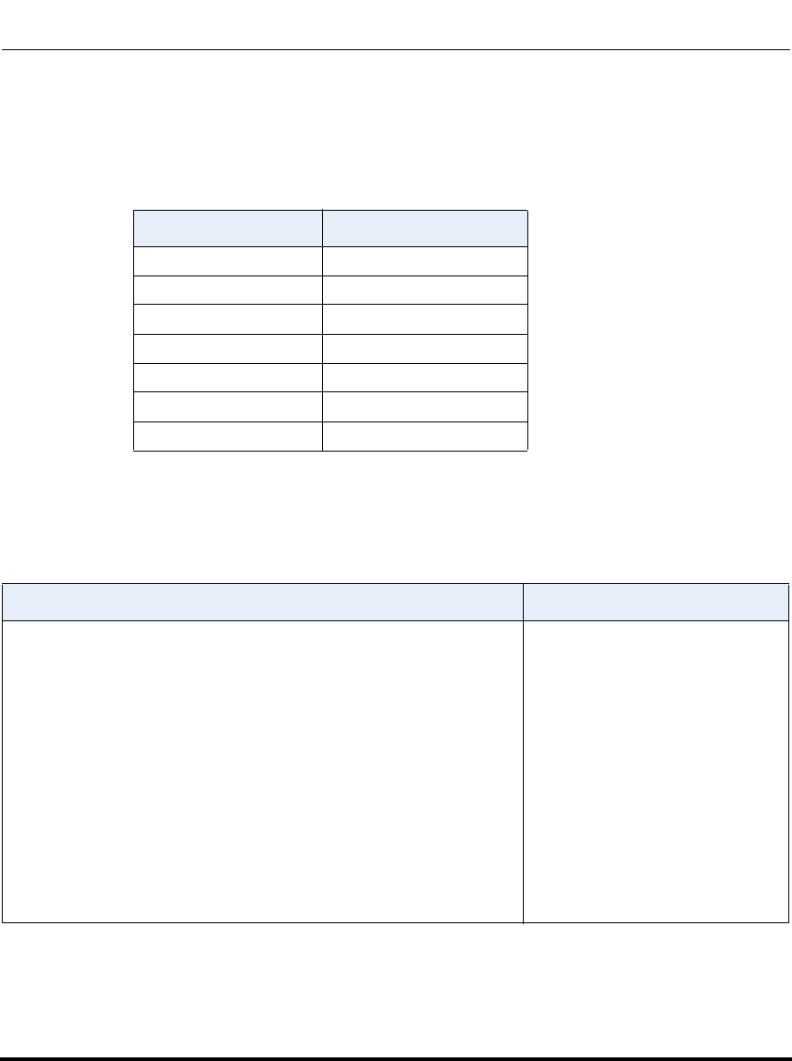
Operational, Basic, and Advanced Parameters
41-001160-03, Rev 00, Release 2.4 A-165
The following table identifies the language code to use for the IP phone language
packs.
Language Codes (from Standard ISO 639)
The following table identifies the country codes to use for the IP phone language
packs.
Country Codes (from Standard ISO 3166)
Language Language Code
English en
European French fr
French Canadian fr_ca
European Spanish es
Mexican Spanish es_mx
German de
Italian it
Country Country Code
AFGHANISTAN
ÅLAND ISLANDS
ALBANIA
ALGERIA
AMERICAN SAMOA
ANDORRA
ANGOLA
ANGUILLA
ANTARCTICA
ANTIGUA AND BARBUDA
ARGENTINA
ARMENIA
ARUBA
AUSTRALIA
AUSTRIA
AZERBAIJAN
AF
AX
AL
DZ
AS
AD
AO
AI
AQ
AG
AR
AM
AW
AU
AT
AZ
Draft 1

Operational, Basic, and Advanced Parameters
A-166 41-001160-03, Rev 00, Release 2.4
IP Phone Administrator Guide
BAHAMAS
BAHRAIN
BANGLADESH
BARBADOS
BELARUS
BELGIUM
BELIZE
BENIN
BERMUDA
BHUTAN
BOLIVIA
BOSNIA AND HERZEGOVINA
BOTSWANA
BOUVET ISLAND
BRAZIL
BRITISH INDIAN OCEAN TERRITORY
BRUNEI DARUSSALAM
BULGARIA
BURKINA FASO
BURUNDI
BS
BH
BD
BB
BY
BE
BZ
BJ
BM
BT
BO
BA
BW
BV
BR
IO
BN
BG
BF
BI
CAMBODIA
CAMEROON
CANADA
CAPE VERDE
CAYMAN ISLANDS
CENTRAL AFRICAN REPUBLIC
CHAD
CHILE
CHINA
CHRISTMAS ISLAND
COCOS (KEELING) ISLANDS
COLOMBIA
COMOROS
CONGO
CONGO, THE DEMOCRATIC REPUBLIC OF THE
COOK ISLANDS
COSTA RICA
CÔTE D'IVOIRE
CROATIA
CUBA
CYPRUS
CZECH REPUBLIC
KH
CM
CA
CV
KY
CF
TD
CL
CN
CX
CC
CO
KM
CG
CD
CK
CR
CI
HR
CU
CY
CZ
Country Country Code
Draft 1

Operational, Basic, and Advanced Parameters
41-001160-03, Rev 00, Release 2.4 A-167
DENMARK
DJIBOUTI
DOMINICA
DOMINICAN REPUBLIC
DK
DJ
DM
DO
ECUADOR
EGYPT
EL SALVADOR
EQUATORIAL GUINEA
ERITREA
ESTONIA
ETHIOPIA
EC
EG
SV
GQ
ER
EE
ET
FALKLAND ISLANDS (MALVINAS)
FAROE ISLANDS
FIJI
FINLAND
FRANCE
FRENCH GUIANA
FRENCH POLYNESIA
FRENCH SOUTHERN TERRITORIES
FK
FO
FJ
FI
FR
GF
PF
TF
GABON
GAMBIA
GEORGIA
GERMANY
GHANA
GIBRALTAR
GREECE
GREENLAND
GRENADA
GUADELOUPE
GUAM
GUATEMALA
GUERNSEY
GUINEA
GUINEA-BISSAU
GUYANA
GA
GM
GE
DE
GH
GI
GR
GL
GD
GP
GU
GT
GG
GN
GW
GY
HAITI
HEARD ISLAND AND MCDONALD ISLANDS
HOLY SEE (VATICAN CITY STATE)
HONDURAS
HONG KONG
HUNGARY
HT
HM
VA
HN
HK
HU
Country Country Code
Draft 1

Operational, Basic, and Advanced Parameters
A-168 41-001160-03, Rev 00, Release 2.4
IP Phone Administrator Guide
ICELAND
INDIA
INDONESIA
IRAN, ISLAMIC REPUBLIC OF
IRAQ
IRELAND
ISLE OF MAN
ISRAEL
ITALY
IS
IN
ID
IR
IQ
IE
IM
IL
IT
JAMAICA
JAPAN
JERSEY
JORDAN
JM
JP
JE
JO
KAZAKHSTAN
KENYA
KIRIBATI
KOREA, DEMOCRATIC PEOPLE'S REPUBLIC OF
KOREA, REPUBLIC OF
KUWAIT
KYRGYZSTAN
KZ
KE
KI
KP
KR
KW
KG
LAO PEOPLE'S DEMOCRATIC REPUBLIC
LATVIA
LEBANON
LESOTHO
LIBERIA
LIBYAN ARAB JAMAHIRIYA
LIECHTENSTEIN
LITHUANIA
LUXEMBOURG
LA
LV
LB
LS
LR
LY
LI
LT
LU
Country Country Code
Draft 1

Operational, Basic, and Advanced Parameters
41-001160-03, Rev 00, Release 2.4 A-169
MACAO
MACEDONIA, THE FORMER YUGOSLAV REPUBLIC OF
MADAGASCAR
MALAWI
MALAYSIA
MALDIVES
MALI
MALTA
MARSHALL ISLANDS
MARTINIQUE
MAURITANIA
MAURITIUS
MAYOTTE
MEXICO
MICRONESIA, FEDERATED STATES OF
MOLDOVA, REPUBLIC OF
MONACO
MONGOLIA
MONTENEGRO
MONTSERRAT
MOROCCO
MOZAMBIQUE
MYANMAR
MO
MK
MG
MW
MY
MV
ML
MT
MH
MQ
MR
MU
YT
MX
FM
MD
MC
MN
ME
MS
MA
MZ
MM
NAMIBIA
NAURU
NEPAL
NETHERLANDS
NETHERLANDS ANTILLES
NEW CALEDONIA
NEW ZEALAND
NICARAGUA
NIGER
NIGERIA
NIUE
NORFOLK ISLAND
NORTHERN MARIANA ISLANDS
NORWAY
NA
NR
NP
NL
AN
NC
NZ
NI
NE
NG
NU
NF
MP
NO
OMAN OM
Country Country Code
Draft 1

Operational, Basic, and Advanced Parameters
A-170 41-001160-03, Rev 00, Release 2.4
IP Phone Administrator Guide
PAKISTAN
PALAU
PALESTINIAN TERRITORY, OCCUPIED
PANAMA
PAPUA NEW GUINEA
PARAGUAY
PERU
PHILIPPINES
PITCAIRN
POLAND
PORTUGAL
PUERTO RICO
PK
PW
PS
PA
PG
PY
PE
PH
PN
PL
PT
PR
QATAR QA
RÉUNION
ROMANIA
RUSSIAN FEDERATION
RWANDA
RE
RO
RU
RW
Country Country Code
Draft 1

Operational, Basic, and Advanced Parameters
41-001160-03, Rev 00, Release 2.4 A-171
SAINT HELENA
SAINT KITTS AND NEVIS
SAINT LUCIA
SAINT PIERRE AND MIQUELON
SAINT VINCENT AND THE GRENADINES
SAMOA
SAN MARINO
SAO TOME AND PRINCIPE
SAUDI ARABIA
SENEGAL
SERBIA
SEYCHELLES
SIERRA LEONE
SINGAPORE
SLOVAKIA
SLOVENIA
SOLOMON ISLANDS
SOMALIA
SOUTH AFRICA
SOUTH GEORGIA AND THE SOUTH SANDWICH ISLANDS
SPAIN
SRI LANKA
SUDAN
SURINAME
SVALBARD AND JAN MAYEN
SWAZILAND
SWEDEN
SWITZERLAND
SYRIAN ARAB REPUBLIC
SH
KN
LC
PM
VC
WS
SM
ST
SA
SN
RS
SC
SL
SG
SK
SI
SB
SO
ZA
GS
ES
LK
SD
SR
SJ
SZ
SE
CH
SY
TAIWAN, PROVINCE OF CHINA
TAJIKISTAN
TANZANIA, UNITED REPUBLIC OF
THAILAND
TIMOR-LESTE
TOGO
TOKELAU
TONGA
TRINIDAD AND TOBAGO
TUNISIA
TURKEY
TURKMENISTAN
TURKS AND CAICOS ISLANDS
TUVALU
TW
TJ
TZ
TH
TL
TG
TK
TO
TT
TN
TR
TM
TC
TV
Country Country Code
Draft 1

Operational, Basic, and Advanced Parameters
A-172 41-001160-03, Rev 00, Release 2.4
IP Phone Administrator Guide
UGANDA
UKRAINE
UNITED ARAB EMIRATES
UNITED KINGDOM
UNITED STATES
UNITED STATES MINOR OUTLYING ISLANDS
URUGUAY
UZBEKISTAN
UG
TA
AE
GB
US
TM
UY
UZ
VANUATU
Vatican City State
VENEZUELA
VIET NAM
VIRGIN ISLANDS, BRITISH
VIRGIN ISLANDS, U.S.
VU
see HOLY SEE
VE
VN
VG
VI
WALLIS AND FUTUNA
WESTERN SAHARA WF
EH
YEMEN YE
Zaire
ZAMBIA
ZIMBABWE
see CONGO, THE DEMOCRATIC
REPUBLIC OF THE
ZM
ZW
Country Country Code
Draft 1

Operational, Basic, and Advanced Parameters
41-001160-03, Rev 00, Release 2.4 A-173
Suppress DTMF Playback Setting
Parameter –
suppress dtmf playback
Suppress DTMF Playback
(in Web UI)
Aastra Web UI Basic Settings->Preferences
Configuration Files aastra.cfg, <mac>.cfg
Description Enables and disables suppression of DTMF playback when a number is
dialed from the softkeys or programmable keys.
When you disable the suppression of DTMF playback and you press a
softkey or programmable key, the IP phone dials the stored number and
displays each digit as dialed in the LCD window. When you enable the
suppression of DTMF playback, the IP phone dials the stored number and
displays the entire number immediately in the LCD window, allowing the
call to be dialed faster.
Format Boolean
Default Value 0 (disabled)
Range 0 (disabled)
1 (enabled)
Example suppress dtmf playback: 1
Draft 1

Operational, Basic, and Advanced Parameters
A-174 41-001160-03, Rev 00, Release 2.4
IP Phone Administrator Guide
Display DTMF Digits Setting
Parameter –
display dtmf digits
Display DTMF Digits
(in Web UI)
Aastra Web UI Basic Settings->Preferences->General
Configuration Files aastra.cfg, <mac>.cfg
Description Enables and disables the display of DTMF digits when dialing on the IP
phone.
DTMF is the signal sent from the phone to the network that you generate
when you press the phone’s touch keys. This is also known as “touchtone”
dialing. Each key you press on your phone generates two tones of specific
frequencies. One tone is generated from a high-frequency group of tones
and the other from a low frequency group.
If enabled, this parameter displays the digits on the IP phone display if you
are dialing from the keypad, or from a softkey or programmable key. This
parameter is disabled by default (no digits display when dialing).
Format Boolean
Default Value 0 (disabled)
Range 0 (disabled)
1 (enabled)
Example display dtmf digits: 1
Draft 1

Operational, Basic, and Advanced Parameters
41-001160-03, Rev 00, Release 2.4 A-175
Intercom, Auto-Answer, and Barge In Settings
Outgoing Intercom Settings
Parameter –
sip intercom type
Type
(in Web UI)
Aastra Web UI Basic Settings->Preferences->
Outgoing Intercom Settings
Configuration Files aastra.cfg, <mac>.cfg
Description Determines whether the IP phone or the server is responsible for notifying
the recipient that an Intercom call is being placed.
Format Integer
Default Value For Aastra Web UI:
Off
For Configuration Files:
3 - Off
Range For Aastra Web UI:
Phone-Side
Server-Side
Off
For Configuration Files:
1 - Phone-Side
2 - Server-Side
3 - Off
Example sip intercom type: 1
Draft 1

Operational, Basic, and Advanced Parameters
A-176 41-001160-03, Rev 00, Release 2.4
IP Phone Administrator Guide
Parameter –
sip intercom prefix code
Prefix Code
(in Web UI)
Aastra Web UI Basic Settings->Preferences->
Outgoing Intercom Settings
Configuration Files aastra.cfg, <mac>.cfg
Description The prefix to add to the phone number for server-side outgoing Intercom
calls. This parameter is required for all server-side Intercom calls.
Note: The example below shows *96 for the prefix code which is used for
Sylantro servers.
Format String
Default Value N/A
Range N/A
Example sip intercom prefix code: *96
Parameter –
sip intercom line
Line
(in Web UI)
Aastra Web UI Basic Settings->Preferences->
Outgoing Intercom Settings
Configuration Files aastra.cfg, <mac>.cfg
Description Specifies the line for which the IP phone uses the configuration from,
when making the Intercom call. The IP phone uses the first available line
for physically making the call but uses the configuration from the line you
set for this parameter.
Note: The "sip intercom type" parameter must be set with the Server-Side
option to enable the "sip intercom line" parameter.
Format Integer
Default Value 1
Range Line 1 through 9
Example sip intercom line: 1
Draft 1

Operational, Basic, and Advanced Parameters
41-001160-03, Rev 00, Release 2.4 A-177
Incoming Intercom Settings
Parameter –
sip allow auto answer
Auto-Answer
(in Web UI)
Aastra Web UI Basic Settings->Preferences->
Incoming Intercom Settings
Configuration Files aastra.cfg, <mac>.cfg
Description Enables or disables the IP phone to allow automatic answering for an
Intercom call. If auto-answer is enabled on the IP phone, the phone plays
a tone to alert the user before answering the intercom call. If auto-answer
is disabled, the phone rejects the incoming intercom call and sends a busy
signal to the caller.
Format Boolean
Default Value 1 (true)
Range 0 (false - do not allow auto-answer)
1 (true - allow auto-answer)
Example sip allow auto answer: 0
Parameter –
sip intercom mute mic
Microphone Mute
(in Web UI)
Aastra Web UI Basic Settings->Preferences->
Incoming Intercom Settings
Configuration Files aastra.cfg, <mac>.cfg
Description Enables or disables the microphone on the IP phone for Intercom calls
made by the originating caller.
Format Integer
Default Value 1 (true)
Range 0 (false - microphone is not muted)
1 (true - microphone is muted)
Example sip intercom mute mic: 1
Draft 1

Operational, Basic, and Advanced Parameters
A-178 41-001160-03, Rev 00, Release 2.4
IP Phone Administrator Guide
Parameter –
sip intercom warning tone
Play Warning Tone
(in Web UI)
Aastra Web UI Basic Settings->Preferences->
Incoming Intercom Settings
Configuration Files aastra.cfg, <mac>.cfg
Description Enables or disables a warning tone to play when the phone receives an
incoming intercom call on an active line.
Format Integer
Default Value 1 (true)
Range 0 (false - warning tone will not play)
1 (true - warning tone will play)
Example sip intercom warning tone: 0
Parameter –
sip intercom allow barge in
Allow Barge In
(in Web UI)
Aastra Web UI: Basic Settings->Preferences->
Incoming Intercom Settings
Configuration Files aastra.cfg, <mac>.cfg
Description Enable or disables how the phone handles incoming intercom calls while
the phone is on an active call.
When you enable this parameter (1 = enable), which is the default value,
an incoming intercom call takes precedence over any active call, by
placing the active call on hold and automatically answering the intercom
call.
When you disable this parameter (0 = disable), and there is an active call,
the phone treats an incoming intercom call like a normal call and plays the
call warning tone.
Note: After enabling or disabling this feature, it takes affect on the phone
immediately.
Format Boolean
Default Value 1 (true)
Range 0 (false)
1 (true)
Example sip intercom allow barge in: 0
Draft 1

Operational, Basic, and Advanced Parameters
41-001160-03, Rev 00, Release 2.4 A-179
Group Paging RTP Settings
Example
The following is an example of configuring RTP streaming for Paging
applications using the configuration files:
paging addr list: 224.0.0.2:10000,239.0.1.20:15000
softkey1 type: multicast
softkey1 label: Group 1
softkey1 value: 224.0.0.2:10000,239.0.1.20:15000
Parameter –
paging addr list Aastra Web UI: Basic Settings->Preferences->
Group Paging RTP Settings
Configuration Files aastra.cfg, <mac>.cfg
Description Specifies the multicast address(es) and the port on which the phone
listens for incoming multicast RTP packets.
Note: If this field is blank, Paging listening capability is disabled on the
phone.
Format IP Address in dotted decimal format/Port #
Default Value N/A
Range N/A
Example paging addr list: 224.0.0.2:10000,239.0.1.20:15000 0
Draft 1

Operational, Basic, and Advanced Parameters
A-180 41-001160-03, Rev 00, Release 2.4
IP Phone Administrator Guide
Audio Transmit and Receive Gain Adjustment Settings
Parameter –
headset tx gain Configuration Files aastra.cfg, <mac>.cfg
Description This is the increased (+db) or decreased (-db) amount of signal
transmitted from the headset microphone to t he far-end party. The amount
of Tx gain in the IP phone firmware has been reduced to avoid side-tone
and echo on the local and far-end equipment. This parameter allows you
to adjust the Tx gain settings to best suit your comfort level and
deployment environment.
Format Integer
Default Value 0
Range -10 db to +10 db
Example headset tx gain: -5
Parameter –
headset sidetone gain Configuration Files aastra.cfg, <mac>.cfg
Description This is the is the increased (+db) or decreased (-db) amount of sidetone
signal from the headset microphone to the headset speaker. The amount
of sidetone gain in the IP phone firmware has been reduced to avoid
side-tone and echo on the local and far-end equipment. This parameter
allows you to adjust the sidetone gain settings to best suit your comfort
level and deployment environment.
Format Integer
Default Value 0
Range -10 db to +10 db
Example headset sidetone gain: -1
Draft 1

Operational, Basic, and Advanced Parameters
41-001160-03, Rev 00, Release 2.4 A-181
Parameter –
handset tx gain Configuration Files aastra.cfg, <mac>.cfg
Description This is the increased (+db) or decreased (-db) amount of signal
transmitted from the handset microphone to the far-end party. The amount
of Tx gain in the IP phone firmware has been reduced to avoid side-tone
and echo on the local and far-end equipment. This parameter allows you
to adjust the Tx gain settings to best suit your comfort level and
deployment environment.
Format Integer
Default Value 0
Range -10 db to +10 db
Example handset tx gain: -5
Parameter –
handset sidetone gain Configuration Files aastra.cfg, <mac>.cfg
Description This is the increased (+db) or decreased (-db) amount of sidetone signal
from the handset microphone to the handset speaker. The amount of
sidetone gain in the IP phone firmware has been reduced to avoid
side-tone and echo on the local and far-end equipment. This parameter
allows you to adjust the sidetone gain settings to best suit your comfort
level and deployment environment.
Format Integer
Default Value 0
Range -10 db to +10 db
Example handset sidetone gain: -1
Draft 1

Operational, Basic, and Advanced Parameters
A-182 41-001160-03, Rev 00, Release 2.4
IP Phone Administrator Guide
Parameter –
handsfree tx gain Configuration Files aastra.cfg, <mac>.cfg
Description This is the increased (+db) or decreased (-db) amount of signal
transmitted from the base microphone to the far-end party. The amount of
Tx gain in the IP phone firmware has been reduced to avoid side-tone and
echo on the local and far-end equipment. This parameter allows you to
adjust the Tx gain settings to best suit your comfort level and deployment
environment.
Note: The example below increases the speakerphone mic transmit gain
by 10 db.
Format Integer
Default Value 0
Range -10 db to +10 db
Example handsfree tx gain: 10
Draft 1

Operational, Basic, and Advanced Parameters
41-001160-03, Rev 00, Release 2.4 A-183
Parameter –
audio mode IP Phone UI Options->Set Audio
Configuration Files aastra.cfg, <mac>.cfg
Description Allows you to configure how the "handsfree" key on the IP phone operates.
Format Integer
Default Value 0
Range 0 Speaker - Calls can be made or received using the handset or
handsfree speakerphone and can be switched between the two
modes by pressing the d /fkey. When on speaker, you can return to
using the handset by placing the handset on the cradle and
picking it up again.
1 Headset - Calls can be made or received using the headset. Calls
can be switched between the headset and handset by pressing the d
/fkey.
2 Speaker/headset - Incoming calls are sent to the speakerphone. By
pressing the d /f key, you can switch between the handsfree
speakerphone, the headset, and the handset.
3 Headset/speaker - Incoming calls are sent to the headset. By
pressing the d /fkey, you can switch between the headset, the
handsfree speakerphone, and the handset.
Example audio mode: 2
Draft 1

Operational, Basic, and Advanced Parameters
A-184 41-001160-03, Rev 00, Release 2.4
IP Phone Administrator Guide
Directed Call Pickup (BLF or XML Call Interception) Settings
Parameter –
directed call pickup
Directed Call Pickup
(in Web UI)
Aastra Web UI Basic Settings->Preferences
->Directed Call Pickup Settings
Configuration Files aastra.cfg, <mac>.cfg
Description Enables or disables the use of "directed call pickup" feature.
Format Boolean
Default Value 0 (disabled)
Range 0 (disabled)
1 (enabled)
Example directed call pickup: 1
Parameter –
directed call pickup prefix
Directed Call Pickup by Prefix
(in Web UI)
Aastra Web UI Basic Settings->Preferences->
Directed Call Pickup Settings
Configuration Files aastra.cfg, <mac>.cfg
Description Allows you to enter a specific prefix string (depending on what is
available on your server), that the phone automatically dials when
dialing the Directed Call Pickup number.
For example, for Broadsoft servers, you can enter a value of *98 for the
“directed call pickup prefix”. When the phone performs the Directed
Call Pickup after pressing a BLF or BLF/List softkey, the phone
prepends the *98 value to the designated extension of the BLF or BLF/
List softkey when dialing out.
Notes:
1. The default method for the phone to use is Directed Call Pickup over
BLF if the server provides applicable information. If the Directed Call
Pickup over BLF information is missing in the messages to the server,
the Directed Call Pickup by Prefix method is used if a value for the prefix
code exists in the configuration.
2. You can define only one prefix at a time for the entire BLF/List.
3. The phone that picks up displays the prefix code + the extension
number (for example, *981234 where prefix key = *98, extension =
1234).
4. Symbol characters are allowed (for example “*”).
Draft 1

Operational, Basic, and Advanced Parameters
41-001160-03, Rev 00, Release 2.4 A-185
Format Integer
Default Value Not Applicable
Range Not Applicable
Example directed call pickup prefix: *98
Parameter –
play a ring splash
Play a Ring Splash
(in Web UI)
Aastra Web UI Basic Settings->Preferences
->Directed Call Pickup Settings
Configuration Files aastra.cfg, <mac>.cfg
Description Enables or disables the playing of a short "call waiting tone" when there is
an incoming call on the BLF monitored extension. If the host tone is idle,
the tone plays a "ring splash".
Format Boolean
Default Value 0 (disabled)
Range 0 (disabled)
1 (enabled)
Example play a ring splash: 1
Draft 1

Operational, Basic, and Advanced Parameters
A-186 41-001160-03, Rev 00, Release 2.4
IP Phone Administrator Guide
ACD Auto-Available Timer Settings
Parameter –
acd auto available
Auto Available
(in Web UI)
Aastra Web UI Basic Settings->Preferences
->Auto Call Distribution Settings
Configuration Files aastra.cfg, <mac>.cfg
Description Enables or disables the use of the ACD Auto-Available Timer.
Format Boolean
Default Value 0 (disabled)
Range 0 (disabled)
1 (enabled)
Example acd auto available: 1
Parameter –
acd auto available timer
Auto Available Timer
(in Web UI)
Aastra Web UI Basic Settings->Preferences
->Auto Call Distribution Settings
Configuration Files aastra.cfg, <mac>.cfg
Description Specifies the length of time, in seconds, before the IP phone status
switches back to “available.”
Format Integer
Default Value 60 (seconds)
Range 0 to 120 (seconds)
Example acd auto available timer: 60
Draft 1

Operational, Basic, and Advanced Parameters
41-001160-03, Rev 00, Release 2.4 A-187
Park and Pickup Global Settings (9480i, 9480i CT, 6757i/6757i CT only)
Parameter –
sprecode
Park Call
(in Web UI)
Aastra Web UI Basic Settings->Preferences
Configuration Files aastra.cfg, <mac>.cfg
Description Specifies the code to enter before entering the extension for where you
want to park an incoming call. The applicable value is dependant on the
type of server in the network:
Server Park Values*
Asterisk 70
Sylantro *98
BroadWorks *68
ININ PBX callpark
*Leave "value" fields blank to disable the park and pickup feature.
Format Alphanumeric characters
Default Value <Blank>
Range See applicable values in the table above.
Example sprecode: *68
Draft 1

Operational, Basic, and Advanced Parameters
A-188 41-001160-03, Rev 00, Release 2.4
IP Phone Administrator Guide
Parameter –
pickupsprecode
Pick Up Parked Call
(in Web UI)
Aastra Web UI Basic Settings->Preferences
Configuration Files aastra.cfg, <mac>.cfg
Description Specifies the code to enter before entering the extension for where you
want to pickup a parked call. The applicable value is dependant on the
type of server in the network:
Server Pickup Values*
Asterisk 70
Sylantro *99
BroadWorks *88
ININ PBX pickup
*Leave "value" fields blank to disable the park and pickup feature.
Format Alphanumeric characters
Default Value <Blank>
Range See applicable values in the table above.
Example pickupsprecode: *88
Draft 1

Operational, Basic, and Advanced Parameters
41-001160-03, Rev 00, Release 2.4 A-189
Mapping Key Settings
This section provides the hard key settings you can use to enable and disable the
Redial, Conf, and Xfer keys on the IP phone.
Parameter –
redial disabled Configuration Files aastra.cfg, <mac>.cfg
Description Enables or disables the Redial key on the IP phone. If this parameter is set
to 0, the key is active and can be pressed by the user. If this parameter is
set to 1, pressing the Redial key is ignored, and the dialed number is not
saved to the "Redial List".
Format Boolean
Default Value 0 (false)
Range 0 (false), 1 (true)
Example redial disabled: 1
Parameter –
conference disabled Configuration Files aastra.cfg, <mac>.cfg
Description Enables or disables the Conf key on the IP phone. If this parameter is set
to 0, the key is active and can be pressed by the user. If this parameter is
set to 1, pressing the Conf key is ignored.
Format Boolean
Default Value 0 (false)
Range 0 (false), 1 (true)
Example conference disabled: 1
Draft 1

Operational, Basic, and Advanced Parameters
A-190 41-001160-03, Rev 00, Release 2.4
IP Phone Administrator Guide
Parameter –
call transfer disabled Configuration Files aastra.cfg, <mac>.cfg
Description Enables or disables the Xfer key on the IP phone. If this parameter is set
to 0, the key is active and can be pressed by the user. If this parameter is
set to 1, pressing the Xfer key is ignored.
Format Boolean
Default Value 0 (false)
Range 0 (false), 1 (true)
Example call transfer disabled: 1
Parameter –
map redial key to
Map Redial Key To
(in Web UI)
Aastra Web UI Basic Settings->Preferences->Key Mapping
Configuration Files aastra.cfg, <mac>.cfg
Description Sets the Redial key as a speeddial key if a value is entered for this
parameter. If you leave this parameter blank, the Redial key returns to its
original functionality.
Note: If you configure the Redial key for speeddialing on the 6757i CT
Base Station, the Redial key on the 6757i CT handset retains its original
functionality. The Redial key on the handset is not configured for
speeddial.
Format Integer
Default Value N/A
Range N/A
Example map redial key to: 5551234
Draft 1

Operational, Basic, and Advanced Parameters
41-001160-03, Rev 00, Release 2.4 A-191
Parameter –
map conf key to
Map Conf Key To
(in Web UI)
Aastra Web UI Basic Settings->Preferences->Key Mapping
Configuration Files aastra.cfg, <mac>.cfg
Description Sets the Conf key as a speeddial key if a value is entered for this
parameter. If you leave this parameter blank, the Conf key returns to its
original functionality.
Note: If you configure the Conf key for speeddialing on the 6757i CT Base
Station, the Conf key on the 6757i CT handset retains its original
functionality. The Conf key on the handset is not configured for speeddial.
Format Integer
Default Value N/A
Range N/A
Example map conf key to: 5551267
Draft 1
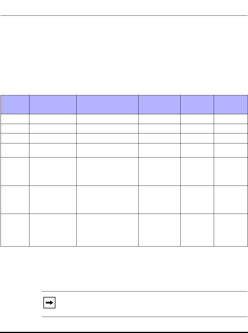
Softkey/Programmable Key/Feature Key/Expansion Module Key Parameters
A-192 41-001160-03, Rev 00, Release 2.4
IP Phone Administrator Guide
Softkey/Programmable Key/Feature Key/
Expansion Module Key Parameters
This section provides the softkey, programmable key, feature key, and expansion
module key parameters you can configure on the IP phones. The following table
provides the number of keys you can configure for each model phone and
expansion module, and the number of lines available for each type of phone.
*The M670i expansion module consists of 36 softkeys. You can have up to 3 expansion modules on an IP
phone totaling 108 softkeys. Valid for 6753i, 6755i, 6757i, and 6757i CT phones.
**The M675i expansion module consists of 60 softkeys. You can have up to 3 expansion modules on an IP
phone totaling 180 softkeys. Valid for 6755i, 6757i, and 6757i CT phones.
***On the 6753i, two of the 6 programmable keys are the DELETE and SAVE keys and can be programmed
only if Administrator allows.
IP Phone
Model Softkeys Expansion Module
Keys Programmable
Keys Lines
Available
Handset
Keys
Available
9143i - Not Applicable 7 9-
9480i 6 Not Applicable - 9-
9480i CT 6 Not Applicable - 915
6753i - 36 to 108*
(Model M670i) 6*** 9-
6755i 6 Bottom Keys 36 to 108*
(Model M670i)
60 to 180**
(Model M675i)
6 Top Keys 9-
6757i 12 Top and
Bottom Softkeys 36 to 108*
(Model M670i)
60 to 180**
(Model M675i)
-9-
6757i CT 12 Top and
Bottom Softkeys 36 to 108* on Base
Station
60 to 180** on Base
Station
(Model M675i)
-915
Note: When entering definitions for softkeys, the “#” sign must be
enclosed in quotes.
Draft 1

Softkey/Programmable Key/Feature Key/Expansion Module Key Parameters
41-001160-03, Rev 00, Release 2.4 A-193
Softkey Settings for 9480i, 9480i CT, 6755i, 6757i, 6757i CT
The value of "N" for the following parameters is dependent on the number of
softkeys available on the 9480i, 9480i CT, 6755i, 6757i, and 6757i CT models.
See the table above for applicable values.
Parameter –
softkeyN type
Type
(in Web UI)
Aastra Web UI Operation->Softkeys and XML
Configuration Files aastra.cfg, <mac>.cfg
Description The type of softkey to configure. Valid types are:
•none - Indicates softkey key is disabled.
•line - Indicates softkey is configured for line use.
•speeddial - Indicates softkey is configured for speeddial use.
Speeddial is applicable to the M670i and M675i also. You can
configure a softkey to speeddial a specific number by pressing that
softkey. Optionally, you can also configure a speeddial key to dial
prefix numbers. With this option, the prefix numbers automatically dial
when you press the softkey, and the phone waits for you to enter the
remaining numbers to dial out.
Note: When there is an active call, the speeddial keys send DTMF
digits through the active voice path. To dial out, you have to first put
the active call on hold and then press the speeddial key.
•dnd - Indicates softkey is configured for do not disturb on the phone.
This option is "Do Not Disturb" in the Aastra Web UI). You must also
set the DND key mode. See
•blf - Indicates softkey is configured for Busy Lamp Field (BLF) use.
User can dial out on a BLF configured key. Maximum of 50 BLFs are
applicable to the M670i and M675i also.
•list - Indicates softkey is configured for BLF list use. (This option is
BLF/List in the Aastra Web UI). User can dial out on a BLF List
configured key. You can also use the “BLF List URI” parameter to
specify a URI for the phone to access for the BLF List.
•acd - (for Sylantro Servers only) Indicates the programmable key is
configured for auto call distribution (called “Auto call distribution” in
the Aastra Web UI). The ACD feature allows the Sylantro server to
distribute calls from a queue to registered IP phone users (agents).
•dcp - (for Sylantro Servers only) Indicates the programmable key is
configured for either directed call pickup or group call pickup (called
“Directed Call Pickup” in the Aastra Web UI). The Directed Call
Pickup/Group Call Pickup feature allows you to intercept or pickup a
call on a monitored extension or a group of monitored extensions.
•xml - Indicates the softkey is configured to accept an XML application
for accessing customized XML services. You can also specify an XML
softkey URL for this option.
Draft 1

Softkey/Programmable Key/Feature Key/Expansion Module Key Parameters
A-194 41-001160-03, Rev 00, Release 2.4
IP Phone Administrator Guide
•webapps - Indicates the softkey is hardcoded to access an Aastra
XML-based application (xml.myaastra.com). By default, Softkey 1 is
assigned as the WebApps key on the 9480i, 9480i CT, 6755i, 6757i,
and 6757i CT. (Not applicable to the CT handsets). Also accessible
from the Services menu on these phones.
•flash - Indicates the softkey is set to generate a flash event when it is
pressed, or a feature key is pressed on the CT handsets. The IP
phone generates flash events only when a call is connected and there
is an active RTP stream (for example, when the call is not on hold).
•sprecode - Indicates the softkey is configured to automatically
activate specific services offered by the server. For example, if the
sprecode value of *82 is configured, then by pressing the softkey, *82
automatically activates a service provided by the server.
•park - Indicates the softkey is configured to park incoming calls when
pressed.
•pickup - Indicates the softkey is configured to pick up parked calls
when pressed.
•lcr - Indicates the softkey is configured for “last call return” when
pressed.
•call forward - Indicates the softkey is configured for accessing the
Call Forward features on the phone. A Call Forwarding Mode must be
enabled to use this softkey. “Account” mode is the default.
•blf/xfer - Indicates the softkey is configured to transfer calls AND
configured for BLF on a single key.
•speeddial/xfer - Indicates the softkey is configured to transfer calls
AND configured for speeddialing to a specific number.
•speeddial/conf - Indicates the softkey is configured to be used as a
speeddial key AND as a conference key.
•dir - Indicates the softkey is set for accessing the Directory List.
•callers - Indicates the softkey is set for accessing the Callers List.
•icom - Indicates the softkey is set to be used as the Intercom key.
•services - Indicates the softkey is set to be used as the Services key.
•phonelock - Indicates the softkey is set to be used to lock/unlock the
phone.
•paging - Indicates the softkey is set for Group Paging on the phone.
Pressing this key automatically sends a Real Time Transport Protocol
(RTP) stream to pre-configured multicast address(es) without
involving SIP signaling.
•empty - Indicates the softkey is configured to force a blank entry on
the IP phone display for a specific softkey.
The softkeys are added in order (from softkey1 to softkey20) after any
hard-coded keys have been added. If a particular soft key is not defined,
it is ignored.
Format Text
Default Value none
Draft 1

Softkey/Programmable Key/Feature Key/Expansion Module Key Parameters
41-001160-03, Rev 00, Release 2.4 A-195
Range none
line
speeddial
dnd ("do not disturb" in the Aastra Web UI)
blf
list ("BLF\List" in the Aastra Web UI)
acd (“Auto call distribution” in the Aastra Web UI)
dcp (“Directed Call Pickup” in the Aastra Web UI)
xml
webapps
flash
sprecode
park
pickup
lcr
call forward
blf/xfer
speeddial/xfer
speeddial/conf
callers (“Callers List” in Aastra Web UI)
dir
icom
services
phonelock
paging
empty
Example softkey1 type: line
softkey2 type: speeddial
softkey3 type: lcr
softkey4 type: xml
Directed Call Pickup on Extension 2200
softkey2 type: dcp
softkey2 label: dcp2200
softkey2 value: 2200
softkey2 states: incoming outgoing idle connected
Group Call Pickup on group_A
softkey3 type: dcp
softkey3 label: gcp_A
softkey3 value: groupcallpickup
softkey3 states: incoming outgoing idle connected
Draft 1

Softkey/Programmable Key/Feature Key/Expansion Module Key Parameters
A-196 41-001160-03, Rev 00, Release 2.4
IP Phone Administrator Guide
Parameter –
softkeyN label
Label
(in Web UI)
Aastra Web UI Operation->Softkeys and XML
Configuration Files aastra.cfg, <mac>.cfg
Description The text label that displays on the IP phone for the softkey.
The “softkeyN label” parameter can be set for the following softkey types
only:
• speeddial
•blf
•acd
•dcp
•xml
• webapps
•flash
• sprecode
•park
• pickup
• blf/xfer
• speeddial/xfer
• speeddial/conf
•dir
•callers
• icom
• services
•paging
Notes:
1. For the 9480i, 9480i CT, 6757i, and 6757i CT phones, an icon
appears beside the soft key label that indicates the status of the line.
2. If the softkeyN type parameter is set to "flash", and no label value is
entered for the softkeyN label parameter, the label of "Flash" is used.
Format Text
Default Value Not Applicable
Range For line, blf types - Up to 9 characters.
For speeddial type - Up to 11 characters.
Example softkey1 label: “Line 9”
softkey2 label: “info”
softkey3 label: flash
softkey4 label: “johnsmith”
Draft 1

Softkey/Programmable Key/Feature Key/Expansion Module Key Parameters
41-001160-03, Rev 00, Release 2.4 A-197
Parameter –
softkeyN value
Value
(In Web UI)
Aastra Web UI Operation->Softkeys and XML
Configuration Files aastra.cfg, <mac>.cfg
Description This is the value you assign to the softkey.
The “softkeyN value” parameter can be set for the following softkey types
only:
• speeddial (you can enter a speeddial number for this field;
optionally, you can also enter a prefix for the
speeddial value to allow the phone to dial the prefix
after you press the speeddial softkey; you then
enter the rest of the number from the keypad on the
phone.)
•blf
• sprecode
•park
• pickup
•dcp
•xml
•blf/xfer
• speeddial/xfer
• speeddial/conf
• paging
Notes:
1. For speeddial - Value is the phone number, extension, or prefix
number to enter for the softkey.
2. For blf - Value is the extension you want to monitor.
3. For sprecode - Value is dependent on services offered by server.
4. For Park, Pickup - For valid values, see Chapter 5, the section,
“Park/Pickup Call Server Configuration Values” on page -238. For
Park/Pickup examples, see Chapter 5, the section, “Model 6757i/
6757i CT and 9480i/9480i CT Examples” on page -236.
5. For xml - You can specify a URI to use for this XML softkey. The
variables you can use with the XML softkey URI are:
• $$SIPUSERNAME$$
• $$SIPAUTHNAME$$
• $$PROXYURL$$
• $$LINESTATE$$
• $$LOCALIP$$
• $$REMOTENUMBER$$
• $$DISPLAYNAME$$
• $$SIPUSERNAME$$
• $$INCOMINGNAME$$
• $$CALLDURATION$$
• $$CALLDIRECTION$$
Draft 1

Softkey/Programmable Key/Feature Key/Expansion Module Key Parameters
A-198 41-001160-03, Rev 00, Release 2.4
IP Phone Administrator Guide
Format Integer
Default Value Not Applicable
Range N/A
Example softkey1 value: 9
softkey2 value: 411
softkey4 value: http://10.50.10.140 script.pl?name=$$SIPUSERNAME$$
softkey5 value: 123456+ (example of a speeddial prefix)
Draft 1

Softkey/Programmable Key/Feature Key/Expansion Module Key Parameters
41-001160-03, Rev 00, Release 2.4 A-199
Parameter –
softkeyN line
Line
(in Web UI)
Aastra Web UI Operation->Softkeys and XML
Configuration Files aastra.cfg, <mac>.cfg
Description This is the line associated with the softkey you are configuring. The
number of applicable lines available is dependent on the specific IP
phone model.
The “softkeyN line” parameter can be set for the following softkey types
only:
• speeddial
•blf
• blf/list
•acd
•dcp
•park
• pickup
•lcr
•blf/xfer
• speeddial/xfer
• speeddial/conf
Format Integer
Default Value 1
Range 1 through 9
Example softkey1 line: 1
softkey2 line: 5
Draft 1

Softkey/Programmable Key/Feature Key/Expansion Module Key Parameters
A-200 41-001160-03, Rev 00, Release 2.4
IP Phone Administrator Guide
Parameter –
softkeyN states
Idle, Connected, Incoming,
Outgoing, Busy
(in Web UI)
Aastra Web UI Operation->Softkeys and XML
Configuration Files aastra.cfg, <mac>.cfg
Description Displays the status of the phone when a softkey is pressed. You can
enter multiple values (idle, connected, incoming, outgoing, busy) for
the "softkeyN state" parameter.
You must associate the softkeyN state parameter with a specific softkey.
In the following example, the softkeyN states parameter is associated
with softkey 12:
softkey12 type: speeddial
softkey12 label: voicemail
softkey12 value *89
softkey12 states: outgoing
Note: The IP phone idle screen condenses the softkeys. So in the
previous example, softkey 12 will appear in position 1 if no other softkeys
are set. A softkey type of "empty" does not display on the idle screen at
all.
Format Text
Default Value For softkey type - None:
All states disabled
For softkey types - Line, DND, speeddial, BLF, BLF List, dcp, XML,
WebApps, lcr, Call Forward, BLF/Xfer, Speeddial/Xfer, Speeddial/
Conf, Directory, Callers List, Icom, Services, empty:
idle, connected, incoming, outgoing
For softkey type - Flash:
All states disabled
For softkey type - Sprecode, Park:
connected
For softkey type - Pickup:
idle, outgoing
For softkey type - acd:
idle
Draft 1

Softkey/Programmable Key/Feature Key/Expansion Module Key Parameters
41-001160-03, Rev 00, Release 2.4 A-201
Range Valid values are:
idle The phone is not being used.
connected The line currently being displayed is
in an active call (or the call is on hold)
incoming The phone is ringing.
outgoing The user is dialing a number, or the
far-end is ringing.
busy The current line is busy because the line is in use or
the line is set as “Do Not Disturb”
Note: For softkey type, Pickup, values can be: just idle, just outgoing, or
idle outgoing.
Example softkey1 states: idle incoming outgoing
softkey2 states: connected
Draft 1

Softkey/Programmable Key/Feature Key/Expansion Module Key Parameters
A-202 41-001160-03, Rev 00, Release 2.4
IP Phone Administrator Guide
Programmable Key Settings for 9143i, 6753i, and 6755i
• The value of "N" for the following parameters is dependent on the number of
programmable keys available on the phone models. See the table on page 192
for the applicable values.
Parameter –
prgkeyN type
Type
(in Web UI)
Aastra Web UI Operation->Programmable Keys
Configuration Files aastra.cfg, <mac>.cfg
Description The type of programmable key to configure. Valid types are:
•none - Indicates no setting for programmable key.
•line - Indicates programmable key is configured for line use.
•speeddial - Indicates programmable key is configured for speeddial
use. You can configure a programmable key to speeddial a specific
number by pressing that key. Optionally, you can also configure a
speeddial key to dial prefix numbers. With this option, the prefix
numbers automatically dial when you press the programmable key,
and the phone waits for you to enter the remaining numbers to dial.
Note: When there is an active call, the speeddial keys send DTMF
digits through the active voice path. To dial out, you have to first put
the active call on hold and then press the speeddial key.
•dnd - Indicates programmable key is configured for do not disturb
on the phone. This option is "Do Not Disturb" in the Aastra Web
UI).
•blf - Indicates programmable key is configured for Busy Lamp Field
(BLF) use. User can dial out on a BLF configured key.
•list - Indicates programmable key is configured for BLF list use.
User can dial out on a BLF List configured key. You can also use the
“BLF List URI” parameter to specify a URI for the phone to access
for the BLF List.
•acd - (for Sylantro Servers only) Indicates the programmable key is
configured for auto call distribution (called “Auto Call Distribution”
in the Aastra Web UI). The ACD feature allows the Sylantro server
to distribute calls from a queue to registered IP phone users
(agents).
•dcp - (for Sylantro Servers only) Indicates the programmable key is
configured for either directed call pickup or group call pickup (called
“Directed Call Pickup” in the Aastra Web UI). The Directed Call
Pickup/Group Call Pickup feature allows you to intercept or pickup a
call on a monitored extension or a group of monitored extensions.
•xml - Indicates programmable key is configured to accept an XML
application for accessing customized XML services. You can also
specify an XML softkey URL for this option.
•webapps - Indicates the key is hardcoded to access an Aastra
XML-based application (xml.myaastra.com). This option is also
accessible from the Services menu on the 6751i, 6753i, and 9143i.
Draft 1

Softkey/Programmable Key/Feature Key/Expansion Module Key Parameters
41-001160-03, Rev 00, Release 2.4 A-203
•flash - Indicates programmable key is set to generate a flash event
when it is pressed. The IP phone generates flash events only when
a call is connected and there is an active RTP stream (for example,
when the call is not on hold).
•sprecode - Indicates programmable key is configured to
automatically activate specific services offered by the server. For
example, if the sprecode value of *82 is configured, then by
pressing the softkey, *82 automatically activates a service provided
by the server.
•park - Indicates programmable key is configured to park incoming
calls when pressed.
•pickup - Indicates programmable key is configured to pick up
parked calls when pressed.
•lcr - Indicates programmable key is configured for “last call return”
when pressed.
•call forward - Indicates the programmable key is configured for
accessing the Call Forward features on the phone. A Call
Forwarding Mode must be enabled to use this softkey. “Account”
mode is the default.
•blf/xfer - Indicates the programmable key is configured to transfer
calls AND configured for BLF on a single key.
•speeddial/xfer - Indicates the programmable key is configured to
transfer calls AND configured for speeddialing to a specific number.
•speeddial/conf - Indicates the programmable key is configured to
be used as a speeddial key AND as a conference key.
•dir - Indicates programmable key is configured to access the
Directory List.
•callers - Indicates programmable key is configured to access the
Callers List.
•conf - Indicates programmable key is configured as a conference
key. Enter as “conf” in configuration files.
•xfer- Indicates programmable key is configured as a Transfer key
for transferring calls. Enter as “xfer” in configuration files.
•services - Indicates the programmable key is set to be used as the
Services key.
•phonelock - Indicates the programmable key is set to be used to
lock/unlock the phone.
•paging - Indicates the softkey is set for Group Paging on the phone.
Pressing this key automatically sends a Real Time Transport
Protocol (RTP) stream to pre-configured multicast address(es)
without involving SIP signaling.
•empty - Indicates programmable key is configured to force a blank
entry on the IP phone display for a specific programmable key.
Format Text
Default Value Not Applicable
Draft 1

Softkey/Programmable Key/Feature Key/Expansion Module Key Parameters
A-204 41-001160-03, Rev 00, Release 2.4
IP Phone Administrator Guide
Range none
line
speeddial
dnd ("do not disturb" in the Aastra Web UI)
blf
list (“BLF/List” in the Aastra Web UI)
acd (“Auto call distribution” in the Aastra Web UI)
dcp (“Directed Call Pickup” in the Aastra Web UI)
xml
webapps
flash
sprecode
park
pickup
lcr
call forward
directory
callers(“Callers List” in Aastra Web UI)
conf
xfer
blf/xfer
speeddial/xfer
speeddial/conf
phonelock
services
paging
empty
Example prgkey3 type: speeddial
Draft 1

Softkey/Programmable Key/Feature Key/Expansion Module Key Parameters
41-001160-03, Rev 00, Release 2.4 A-205
Parameter –
prgkeyN value
Value
(in Web UI)
Aastra Web UI Operation->Programmable Keys
Configuration Files aastra.cfg, <mac>.cfg
Description This is the value you assign to the programmable key.
The “prgkeyN value” parameter can be set for the following softkey types
only:
• speeddial (you can enter a speeddial number for this field;
optionally, you can also enter a prefix for the
speeddial value to allow the phone to dial the prefix
after you press the speeddial programmable key;
you then enter the rest of the number from the
keypad on the phone.)
•line
•blf
• sprecode
•dcp
•xml
•park
•pickup
•blf/xfer
• speeddial/xfer
• speeddial/conf
•paging
Notes:
1. For speeddial - Value is the phone number, extension, or prefix
number to enter for the programmable key.
2. For line - Value is optional; for example L4.
3. For blf - Value is the extension you want to monitor.
4. For sprecode - Value is dependent on services offered by server.
5. For xml - You can specify a URI to use for this XML softkey. The
variables you can use with the XML softkey URI are:
• $$SIPUSERNAME$$
• $$SIPAUTHNAME$$
• $$PROXYURL$$
• $$LINESTATE$$
• $$LOCALIP$$
• $$REMOTENUMBER$$
• $$DISPLAYNAME$$
• $$SIPUSERNAME$$
• $$INCOMINGNAME$$
• $$CALLDURATION$$
• $$CALLDIRECTION$
6. For Park, Pickup - For valid values, see Chapter 5, the section,
“Park/Pickup Call Server Configuration Values” on page -238. For
Park/Pickup examples, see Chapter 5, the section “Model 6753i and
9143i Examples” on page -237.
Format Integer
Draft 1

Softkey/Programmable Key/Feature Key/Expansion Module Key Parameters
A-206 41-001160-03, Rev 00, Release 2.4
IP Phone Administrator Guide
Default Value N/A
Range N/A
Example prgkey3 value: 411
prgkey4 value: 123456+ (example of a speeddial prefix)
Parameter–
prgkeyN line
Line
(in Web UI)
Aastra Web UI Operation->Programmable Keys
Configuration Files aastra.cfg, <mac>.cfg
Description This is the line associated with the programmable key you are
configuring.
The “prgkeyN line” parameter can be set for the following softkey types
only:
• speeddial
•blf
•blf/List
•acd
•dcp
•park
• pickup
•lcr
• blf/xfer
• speeddial/xfer
• speeddial/conf
Format Integer
Default Value 1
Range 1 through 9
Example prgkey3 line: 1
prgkey4 line: 5
Draft 1

Softkey/Programmable Key/Feature Key/Expansion Module Key Parameters
41-001160-03, Rev 00, Release 2.4 A-207
Top Softkey Settings for 6757i and 6757i CT
Parameter –
topsoftkeyN type
Top Softkeys->Type
(in Web UI)
Aastra Web UI Operation->Softkeys and XML
Configuration Files aastra.cfg, <mac>.cfg
Description The type of softkey to configure. Valid types are:
•none - Indicates softkey is disabled.
•line - Indicates softkey is configured for line use.
•speeddial - Indicates softkey is configured for speeddial use.
You can configure a softkey to speeddial a specific number by
pressing that softkey. Optionally, you can also configure a speeddial
key to dial prefix numbers. With this option, the prefix numbers
automatically dial when you press the softkey, and the phone waits
for you to enter the remaining numbers to dial out.
Note: When there is an active call, the speeddial keys send DTMF
digits through the active voice path. To dial out, you have to first put
the active call on hold and then press the speeddial key.
•dnd - Indicates softkey is configured for do not disturb on the phone.
This option is "Do Not Disturb" in the Aastra Web UI).
•blf - Indicates softkey is configured for Busy Lamp Field (BLF) use.
User can dial out on a BLF configured key.
•list - Indicates softkey is configured for BLF list use. (This option is
BLF/List in the Aastra Web UI). User can dial out on a BLF List
configured key. You can also use the “BLF List URI” parameter to
specify a URI for the phone to access for the BLF List.
•acd - (for Sylantro Servers only) Indicates the programmable key is
configured for auto call distribution (called “Auto call distribution” in
the Aastra Web UI). The ACD feature allows the Sylantro server to
distribute calls from a queue to registered IP phone users (agents).
•dcp - (for Sylantro Servers only) Indicates the programmable key is
configured for either directed call pickup or group call pickup (called
“Directed Call Pickup” in the Aastra Web UI). The Directed Call
Pickup/Group Call Pickup feature allows you to intercept or pickup a
call on a monitored extension or a group of monitored extensions.
•xml - Indicates the softkey is configured to accept an XML application
for accessing customized XML services. You can also specify an XML
softkey URL for this option.
•webapps - Indicates the softkey is hardcoded to access an Aastra
XML-based application (xml.myaastra.com). By default, Softkey 1 is
assigned as the WebApps key on the 9480i, 9480i CT, 6755i, 6757i,
and 6757i CT. (Not applicable to the CT handsets). Also accessible
from the Services menu on these phones.
Draft 1

Softkey/Programmable Key/Feature Key/Expansion Module Key Parameters
A-208 41-001160-03, Rev 00, Release 2.4
IP Phone Administrator Guide
•flash - Indicates the softkey is set to generate a flash event when it is
pressed, or a feature key is pressed on the CT handsets. The IP
phone generates flash events only when a call is connected and there
is an active RTP stream (for example, when the call is not on hold).
•sprecode - Indicates the softkey is configured to automatically
activate specific services offered by the server. For example, if the
sprecode value of *82 is configured, then by pressing the softkey, *82
automatically activates a service provided by the server.
•park - Indicates the softkey is configured to park incoming calls when
pressed.
•pickup - Indicates the softkey is configured to pick up parked calls
when pressed.
•lcr - Indicates the softkey is configured for “last call return” when
pressed.
•call forward - Indicates the softkey is configured for accessing the
Call Forward features on the phone. A Call Forwarding Mode must be
enabled to use this softkey. “Account” mode is the default.
•blf/xfer - Indicates the softkey is configured to transfer calls AND
configured for BLF on a single key.
•speeddial/xfer - Indicates the softkey is configured to transfer calls
AND configured for speeddialing to a specific number.
•speeddial/conf - Indicates the softkey is configured to be used as a
speeddial key AND as a conference key.
•callers - Indicates the softkey is set for accessing the Callers List.
•directory - Indicates the softkey is set for accessing the Directory
List.
•icom - Indicates the softkey is set to be used as the Intercom key.
•services - Indicates the softkey is set to be used as the Services key.
•phonelock - Indicates the softkey is set to be used to lock/unlock the
phone.
•paging - Indicates the softkey is set for Group Paging on the phone.
Pressing this key automatically sends a Real Time Transport Protocol
(RTP) stream to pre-configured multicast address(es) without
involving SIP signaling.
•empty - Indicates the softkey is configured to force a blank entry on
the IP phone display for a specific softkey. The soft keys are added in
order (from softkey1 to softkey20) after any hard-coded keys have
been added. If a particular soft key is not defined, it is ignored.
Format Text
Default Value none
Draft 1

Softkey/Programmable Key/Feature Key/Expansion Module Key Parameters
41-001160-03, Rev 00, Release 2.4 A-209
Range none
line
speeddial
dnd
blf
list ("BLF\List" in the Aastra Web UI)
acd (“Auto call distribution” in the Aastra Web UI)
dcp (“Directed Call Pickup” in the Aastra Web UI)
xml
webapps
flash
sprecode
call forward
park
pickup
blf/xfer
speeddial/xfer
speeddial/conf
lcr
callers (“Callers List” in Aastra Web UI)
directory
icom
services
phonelock
paging
empty
Example topsoftkey1 type: line
topsoftkey2 type: speeddial
topsoftkey3 type: lcr
topsoftkey4 type: xml
Draft 1

Softkey/Programmable Key/Feature Key/Expansion Module Key Parameters
A-210 41-001160-03, Rev 00, Release 2.4
IP Phone Administrator Guide
Parameter –
topsoftkeyN label
Top Softkeys->Label
(in Web UI)
Aastra Web UI Operation->Softkeys and XML
Configuration Files aastra.cfg, <mac>.cfg
Description The text label that displays on the IP phone for the softkey.
The “topsoftkeyN label” parameter can be set for the following softkey
types only:
• speeddial
•blf
•acd
•dcp
•xml
• webapps
•flash
• sprecode
•park
• pickup
• blf/xfer
• speeddial/xfer
• speeddial/conf
•paging
•directory
• callers list
• icom
• services
Notes:
1. For the 6757i and 6757i CT phones, an icon appears beside the soft
key label that indicates the status of the line.
2. If the topsoftkeyN type parameter is set to "flash", and no label value
is entered for the topsoftkeyN label parameter, the label of "Flash" is
used.
Format Text
Default Value Not Applicable
Range For line, blf types - Up to 9 characters.
For speeddial type - Up to 11 characters.
Example topsoftkey1 label: “Line 9”
topsoftkey2 label: “info”
topsoftkey4 label: “johnsmith”
Draft 1

Softkey/Programmable Key/Feature Key/Expansion Module Key Parameters
41-001160-03, Rev 00, Release 2.4 A-211
Parameter –
topsoftkeyN value
Top Softkeys->Value
(In WEb UI)
Aastra Web UI Operation->Softkeys and XML
Configuration Files aastra.cfg, <mac>.cfg
Description This is the value you assign to the softkey.
The “topsoftkeyN value” parameter can be set for the following softkey
types only:
• speeddial (you can enter a speeddial number for this field;
optionally, you can also enter a prefix for the
speeddial value to allow the phone to dial the prefix
after you press the speeddial programmable key;
you then enter the rest of the number from the
keypad on the phone.)
•blf
• sprecode
•park
• pickup
•dcp
•xml
•blf/xfer
• speeddial/xfer
• speeddial/conf
• paging
Notes:
1. For speeddial - Value is the phone number, extension, or prefix
number to enter for the softkey.
2. For blf - Value is the extension you want to monitor.
3. For sprecode - Value is dependent on services offered by server.
4. For Park, Pickup - For valid values, see Chapter 5, the section,
“Park/Pickup Call Server Configuration Values” on page -238. For
Park/Pickup examples, see Chapter 5, the section, “Model 6757i/
6757i CT and 9480i/9480i CT Examples” on page -236.
5. For xml - You can specify a URI to use for this XML softkey. The
variables you can use with the XML softkey URI are:
• $$SIPUSERNAME$$
• $$SIPAUTHNAME$$
• $$PROXYURL$$
• $$LINESTATE$$
• $$LOCALIP$$
• $$REMOTENUMBER$$
• $$DISPLAYNAME$$
• $$SIPUSERNAME$$
• $$INCOMINGNAME$$
• $$CALLDURATION$$
• $$CALLDIRECTION$$
Draft 1

Softkey/Programmable Key/Feature Key/Expansion Module Key Parameters
A-212 41-001160-03, Rev 00, Release 2.4
IP Phone Administrator Guide
Format Integer
Default Value Not Applicable
Range N/A
Example topsoftkey1 value: 9
topsoftkey2 value: 411
topsoftkey4 value: http://10.50.10.140 script.pl?name=$$SIPUSERNAME$$
topsoftkey5 value: 12345+ (example of a speeddial prefix)
Draft 1

Softkey/Programmable Key/Feature Key/Expansion Module Key Parameters
41-001160-03, Rev 00, Release 2.4 A-213
Parameter –
topsoftkeyN line
Top Softkeys->Line
(in Web UI)
Aastra Web UI Operation->Softkeys and XML
Configuration Files aastra.cfg, <mac>.cfg
Description This is the line associated with the softkey you are configuring. The
number of applicable lines available is dependent on the specific IP
phone model.
The “topsoftkeyN line” parameter can be set for the following softkey
types only:
• speeddial
•blf
• blf/list
•acd
•dcp
•park
• pickup
•lcr
•blf/xfer
• speeddial/xfer
• speeddial/conf
Format Integer
Default Value 1
Range 1 through 9
Example topsoftkey1 line: 1
topsoftkey2 line: 5
Draft 1

Softkey/Programmable Key/Feature Key/Expansion Module Key Parameters
A-214 41-001160-03, Rev 00, Release 2.4
IP Phone Administrator Guide
Handset Feature Key Settings for the 9480i CT and 6757i CT
Parameter –
featurekeyN type
Type
(in Web UI)
Aastra Web UI Operation->Handset Keys
Configuration Files aastra.cfg, <mac>.cfg
Description The type of feature key to configure. Valid types are:
•none - Indicates feature key is disabled.
•line - Indicates the feature key is configured for line use.
•xfer- Indicates feature key is configured for transferring a call.
•conf - Indicates feature key is configured for conference calling.
•public - Indicates feature key is configured to toggle from public to
private mode. A public and private softkey can be used when at a line
item in the Directory List. The Private key toggles a number in the
Directory List to private. The Public key allows a number in the
Directory List to be sent to the handsets. A 6757i CT accepts a
maximum of 50 entries with the public attribute.
•icom - Indicates the feature key is set to be used to make an
intercom call.
•dir - Indicates the feature key is set for accessing the Directory List.
•callers - Indicates the feature key is set for accessing the Callers List.
•park- Indicates the feature key is configured to park incoming calls
when pressed.
•pickup- Indicates the feature key is configured to pick up parked calls
when pressed.
•flash - Indicates the feature key is set to generate a flash event when
it is pressed CT handsets. The IP phone generates flash events only
when a call is connected and there is an active RTP stream (for
example, when the call is not on hold).
Format Text
Default Value None
Range none
line
transfer
conference
public
icom
directory
callers (“Callers List” in Aastra Web UI)
park
pickup
flash
Draft 1

Softkey/Programmable Key/Feature Key/Expansion Module Key Parameters
41-001160-03, Rev 00, Release 2.4 A-215
Example featurekey1 type: line
featurekey2 type: public
featurekey3 type: park
featurekey4 type: pickup
Parameter –
featurekeyN label
Label
(in Web UI)
Aastra Web UI Operation->Handset Keys
Configuration Files aastra.cfg, <mac>.cfg
Description The text label that displays on the IP phone for the feature key.
Notes:
1. For the 6757i CT phones, an icon appears beside the feature key
label that indicates the status of the line.
2. If a feature key is configured but no label is set, the IP phone sets the
label to the English, French, or Spanish translation of the chosen
action. The language used is based on the current language of the
cordless handset.
Format Text
Default Value Not Applicable
Range Not Applicable
Example featurekey1 label: Line 9
featurekey2 label: Public
featurekey4 label: John Smith
Draft 1

Expansion Module Key Settings for M670i (6753i, 6755i, 6757i,
6757i CT) and M675i (for 6755i, 6757i, 6757i CT)
Parameter –
expmodX keyN type
Type
(in Web UI)
Aastra Web UI Operation->Expansion Module N
Configuration Files aastra.cfg, <mac>.cfg
Description The type of softkey to configure. Valid types are:
•none - Indicates softkey is disabled.
•line - Indicates softkey is configured for line use.
•speeddial - Indicates softkey is configured for speeddial use.
You can configure a softkey to speeddial a specific number by
pressing that softkey. Optionally, you can also configure a speeddial
key to dial prefix numbers. With this option, the prefix numbers
automatically dial when you press the softkey, and the phone waits
for you to enter the remaining numbers to dial out.
Note: When there is an active call, the speeddial keys send DTMF
digits through the active voice path. To dial out, you have to first put
the active call on hold and then press the speeddial key.
•dnd - Indicates softkey is configured for do not disturb on the phone.
This option is "Do Not Disturb" in the Aastra Web UI).
•blf - Indicates softkey is configured for Busy Lamp Field (BLF) use.
User can dial out on a BLF configured key.
•list - Indicates softkey is configured for BLF list use. (This option is
BLF/List in the Aastra Web UI). User can dial out on a BLF List
configured key. You can also use the “BLF List URI” parameter to
specify a URI for the phone to access for the BLF List.
•acd - (for Sylantro Servers only) Indicates the programmable key is
configured for auto call distribution (called “Auto call distribution” in
the Aastra Web UI). The ACD feature allows the Sylantro server to
distribute calls from a queue to registered IP phone users (agents).
•dcp - (for Sylantro Servers only) Indicates the programmable key is
configured for either directed call pickup or group call pickup (called
“Directed Call Pickup” in the Aastra Web UI). The Directed Call
Pickup/Group Call Pickup feature allows you to intercept or pickup a
call on a monitored extension or a group of monitored extensions.
•xml - Indicates the softkey is configured to accept an XML application
for accessing customized XML services. You can also specify an XML
softkey URL for this option.
•webapps - Indicates the key is hardcoded to access an Aastra
XML-based application (xml.myaastra.com).
•flash - Indicates the softkey is set to generate a flash event when it is
pressed, or a feature key is pressed on the CT handsets. The IP
phone generates flash events only when a call is connected and there
is an active RTP stream (for example, when the call is not on hold).
Draft 1

Softkey/Programmable Key/Feature Key/Expansion Module Key Parameters
41-001160-03, Rev 00, Release 2.4 A-217
Format •sprecode - Indicates the softkey is configured to automatically
activate specific services offered by the server. For example, if the
sprecode value of *82 is configured, then by pressing the softkey, *82
automatically activates a service provided by the server.
•park - Indicates the softkey is configured to park incoming calls when
pressed.
•pickup - Indicates the softkey is configured to pick up parked calls
when pressed.
•lcr - Indicates the softkey is configured for “last call return” when
pressed.
•call forward - Indicates the softkey is configured for accessing the
Call Forward features on the phone. A Call Forwarding Mode must be
enabled to use this softkey. “Account” mode is the default.
•blf/xfer - Indicates the softkey is configured to transfer calls AND
configured for BLF on a single key.
•speeddial/xfer - Indicates the softkey is configured to transfer calls
AND configured for speeddialing to a specific number.
•speeddial/conf - Indicates the softkey is configured to be used as a
speeddial key AND as a conference key.
•callers - Indicates the softkey is set for accessing the Callers List.
•directory - Indicates the softkey is set for accessing the Directory
List.
•icom - Indicates the softkey is set to be used as the Intercom key.
•services - (not available on the 6753i) Indicates the softkey is set to
be used as the Services key.
•phonelock - Indicates the softkey is set to be used to lock/unlock the
phone.
•paging - Indicates the softkey is set for Group Paging on the phone.
Pressing this key automatically sends a Real Time Transport Protocol
(RTP) stream to pre-configured multicast address(es) without
involving SIP signaling.
•empty - Indicates the softkey is configured to force a blank entry on
the IP phone display for a specific softkey. The soft keys are added in
order (from softkey1 to softkey20) after any hard-coded keys have
been added. If a particular soft key is not defined, it is ignored.
Default Value none
Draft 1

Softkey/Programmable Key/Feature Key/Expansion Module Key Parameters
A-218 41-001160-03, Rev 00, Release 2.4
IP Phone Administrator Guide
Range • none
• line
• speeddial
• dnd
•blf
• list ("BLF\List" in the Aastra Web UI)
• acd (“Auto call distribution” in the Aastra Web UI)
• dcp (“Directed Call Pickup” in the Aastra Web UI)
•xml
• webapps
•flash
• sprecode
•park
• pickup
•lcr
• call forward
• blf/xfer
• speeddial/xfer
• speeddial/conf
• callers (“Callers List” in Aastra Web UI)
•directory
• icom
• services (not available on the 6753i)
• phonelock
•paging
•empty
Example expmod1 key1 type: line
expmod1 key2 type: speeddial
expmod1 key3 type: blf
expmod1 key4 type: list
Draft 1

Softkey/Programmable Key/Feature Key/Expansion Module Key Parameters
41-001160-03, Rev 00, Release 2.4 A-219
Parameter –
expmodX keyN label
Label
(in Web UI)
Aastra Web UI Operation->Expansion Module N
Configuration Files aastra.cfg, <mac>.cfg
Description The text label that displays on the softkey for the Expansion Module.
The “expmodX keyN label” parameter can be set for the following
softkey types only:
• speeddial
•blf
•acd
•dcp
•xml
• webapps
•flash
• sprecode
•park
• pickup
•directory
• callers list
• icom
• services
• blf/xfer
• speeddial/xfer
• speeddial/conf
•paging
Notes:
1. For the 9480i, 9480i CT, 6757i, and 6757i CT phones, an icon
appears beside the soft key label that indicates the status of the line.
Format Text
Default Value Not Applicable
Range For line, blf types - Up to 9 characters.
For speeddial type - Up to 11 characters.
Example expmod1 key1 label: “Line 9”
expmod2 key1 label: “info”
expmod3 key1 label: “johnsmith”
Draft 1

Softkey/Programmable Key/Feature Key/Expansion Module Key Parameters
A-220 41-001160-03, Rev 00, Release 2.4
IP Phone Administrator Guide
Parameter –
expmodX keyN value
Value
(In WEb UI)
Aastra Web UI Operation->Expansion Module N
Configuration Files aastra.cfg, <mac>.cfg
Description The text label that displays on the IP phone for the softkey on the
Expansion Module.
The “expmodX keyN value” parameter can be set for the following
softkey types only:
• speeddial
•blf
•dcp
•xml
• sprecode
•park
• pickup
•directory
• callers (“Callers List” in Aastra Web UI)
• icom
• services (not available on 6753i)
•blf/xfer
• speeddial/xfer
• speeddial/conf
• paging
Notes:
1. For the 6757i and 6757i CT phones, an icon appears beside the soft
key label that indicates the status of the line.
2. For blf - Value is the extension you want to monitor.
3. For xml - You can specify a URI to use for this XML softkey. The
variables you can use with the XML softkey URI are:
• $$SIPUSERNAME$$
• $$SIPAUTHNAME$$
• $$PROXYURL$$
• $$LINESTATE$$
• $$LOCALIP$$
• $$REMOTENUMBER$$
• $$DISPLAYNAME$$
• $$SIPUSERNAME$$
• $$INCOMINGNAME$$
• $$CALLDURATION$$
• $$CALLDIRECTION$$
Format Integer
Default Value Not Applicable
Range N/A
Draft 1

Softkey/Programmable Key/Feature Key/Expansion Module Key Parameters
41-001160-03, Rev 00, Release 2.4 A-221
Example expmod1 key1 value: 9
expmod1 key2 value: 411
expmod1 key3 value: 123456+ (example of a speeddial prefix)
Draft 1

Softkey/Programmable Key/Feature Key/Expansion Module Key Parameters
A-222 41-001160-03, Rev 00, Release 2.4
IP Phone Administrator Guide
Parameter –
expmodX keyN line
Line
(in Web UI)
Aastra Web UI Operation->Expansion Module N
Configuration Files aastra.cfg, <mac>.cfg
Description This is the line associated with the softkey you are configuring on the
Expansion Module. The number of applicable lines available is
dependent on the specific IP phone model.
The “expmodX keyN line” parameter can be set for the following softkey
types only:
• speeddial
•blf
• blf/list
•acd
•dcp
•lcr
•park
• pickup
•blf/xfer
• speeddial/xfer
• speeddial/conf
Format Integer
Default Value 1
Range 1 through 9
Example expmod1 key1 line: 1
expmod1 key2 line: 5
Draft 1

Softkey/Programmable Key/Feature Key/Expansion Module Key Parameters
41-001160-03, Rev 00, Release 2.4 A-223
Customizing the Key Type List
Softkeys, Programmable Keys, Expansion Module Keys
Parameter –
softkey selection list Configuration Files aastra.cfg, <mac>.cfg
Description Allows you to specify which key types to display and the order in which to
display them in the “Type” list for softkeys, programmable keys, and/or
expansion module keys when configuring the keys in the Aastra Web UI.
If no value is specified for this “softkey selection list” parameter, the
key “Type” list displays ALL of the key types by default in the Aastra Web
UI.
:
1. Any key types configured that do not apply to the phone’s
environment are ignored.
2. The SAVE and DELETE keys appear by default as
Keys 1 and 2 on the 6753i and 9143i, unless specifically allowed by the
Administrator to be configurable.
3. An Administrator must use the English value when configuring the
key types in the configuration files.
4. Any key type already configured on a phone displays in that key’s
“Type” list, in addition to the values specified for this parameter.
5. After configuring specific key types for a phone, the key types in
the Aastra Web UI display the same for both the User and Administrator
Web interfaces for that phone.
Format Alpha Characters in a comma separated list
Draft 1

Softkey/Programmable Key/Feature Key/Expansion Module Key Parameters
A-224 41-001160-03, Rev 00, Release 2.4
IP Phone Administrator Guide
Default Value
Range Any of the key types in the “Default Value” field above.
Example softkey selection list: blf, speeddial, line, xml
•none •lcr
• line • call forward
• speeddial • blf/xfer
• dnd • speeddial/xfer
• blf • speeddial/conf
• list • directory
•acd •callers
• dcp • conf (6753i, 9143i)
• xml • xfer (6753i, 9143i)
•webapps •icom
• flash • services
• sprecode • phonelock
• park • paging
• pi ckup • empty (6755i, 6757i,
6757 CT, 9480i, 9480i CT)
Draft 1

Softkey/Programmable Key/Feature Key/Expansion Module Key Parameters
41-001160-03, Rev 00, Release 2.4 A-225
Handset Feature Keys (for CT Models ONLY)
Parameter –
feature key selection list Configuration Files aastra.cfg, <mac>.cfg
Description Allows you to specify which key types to display and the order in which to
display them in the “Type” list for the feature keys (CT models only)
when configuring the keys in the Aastra Web UI.
If no value is specified for this “feature key selection list” parameter,
the key “Type” list displays ALL of the key types by default in the Aastra
Web UI.
:
1. Any key types configured that do not apply to the phone’s
environment are ignored.
2. An Administrator must use the English value when configuring the
key types in the configuration files.
3. Any key type already configured on a phone displays in that key’s
“Type” list, in addition to the values specified for this parameter.
4. After configuring specific key types for a phone, the key types in
the Aastra Web UI display the same for both the User and Administrator
Web interfaces for that phone.
Format Alpha Characters in a comma separated list
Default Value
Range Any of the key types in the “Default Value” field above.
Example feature key selection list: line, dir, callers
• none • park
• line • pickup
• icom • conf
•dir •private
• callers • public
• xfer • flash
Draft 1

Softkey/Programmable Key/Feature Key/Expansion Module Key Parameters
A-226 41-001160-03, Rev 00, Release 2.4
IP Phone Administrator Guide
Locking Softkeys and Programmable Keys
Parameter–
softkeyN locked Configuration Files aastra.cfg, <mac>.cfg
Description Locks the specified softkey on the 9480i, 9480i CT, 6755i, 6757i, or 6757i
CT IP phone. Locking the key prevents a user from changing or
configuring the softkey. When a key is locked, the phone uses the server
settings and ignores any previous local configuration.
Affects the following parameters:
• softkeyN type
• softkeyN label
• softkeyN value
• softkeyN line
• softkeyN states
Format Boolean
Default Value 0 (disable)
Range 0 (disable)
1 (enable)
Example softkey1 locked: 1
Parameter–
topsoftkeyN locked Configuration Files aastra.cfg, <mac>.cfg
Description Locks the specified top softkey on the 6757i or 6757i CT IP phone.
Locking the key prevents a user from changing or configuring the softkey.
When a key is locked, the phone uses the server settings and ignores any
previous local configuration.
Affects the following parameters:
• topsoftkeyN type
• topsoftkeyN label
• topsoftkeyN value
• topsoftkeyN line
Format Boolean
Default Value 0 (disable)
Range 0 (disable)
1 (enable)
Example topsoftkey1 locked: 1
Draft 1

Softkey/Programmable Key/Feature Key/Expansion Module Key Parameters
41-001160-03, Rev 00, Release 2.4 A-227
Parameter–
prgkeyN locked Configuration Files aastra.cfg, <mac>.cfg
Description Locks the specified top softkey on the 9143i, 6753i, or 6755i IP phone.
Locking the key prevents a user from changing or configuring the
programmable key. When a key is locked, the phone uses the server
settings and ignores any previous local configuration.
Affects the following parameters:
• prgkeyN type
• prgkeyN value
• prgkeyN line
Format Boolean
Default Value 0 (disable)
Range 0 (disable)
1 (enable)
Example prgkey1 locked: 1
Parameter–
featurekeyN locked Configuration Files aastra.cfg, <mac>.cfg
Description Locks the specified top softkey on the 6757i CT IP phone. Locking the key
prevents a user from changing or configuring the feature key. When a key
is locked, the phone uses the server settings and ignores any previous
local configuration.
Affects the following parameters:
• featurekeyN type
• featurekeyN label
Format Boolean
Default Value 0 (disable)
Range 0 (disable)
1 (enable)
Example featurekey1 locked: 1
Draft 1

Softkey/Programmable Key/Feature Key/Expansion Module Key Parameters
A-228 41-001160-03, Rev 00, Release 2.4
IP Phone Administrator Guide
Parameter–
expmodX keyN locked Configuration Files aastra.cfg, <mac>.cfg
Description Locks the specified top softkey on the 5-Series Expansion Module
attached to the IP phone. Locking the key prevents a user from changing
or configuring the softkey on the expansion module. When a key is
locked, the phone uses the server settings and ignores any previous local
configuration.
Affects the following parameters:
• expmodX keyN type
• expmodX keyN value
• expmodX keyN line
Format Boolean
Default Value 0 (disable)
Range 0 (disable)
1 (enable)
Example expmod1 key4 locked: 1
Draft 1

Softkey/Programmable Key/Feature Key/Expansion Module Key Parameters
41-001160-03, Rev 00, Release 2.4 A-229
Locking the SAVE and DLETE Keys (6753i)
Parameter–
prgkey1 locked Configuration Files aastra.cfg, <mac>.cfg
Description Allows you to lock or unlock the Save key on the 6753i IP Phone. When the
Save key is unlocked, a User can change the function of the key using the
Aastra Web UI. An Administrator can change the function of the key using
the Aastra Web UI or the configuration files.
Note:
1. The save function on the 6753i IP Phone is limited to Key 1 only.
2. Changing the function from the Save key to another function, removes
the ability to save items on the IP phone.
Format Boolean
Default Value 1 (lock)
Range 0 (unlock)
1 (lock)
Example prgkey1 locked: 0
Parameter–
prgkey2 locked Configuration Files aastra.cfg, <mac>.cfg
Description Allows you to lock or unlock the Delete key on the 6753i IP Phone. When the
Delete key is unlocked, a User can change the function of the key using the
Aastra Web UI. An Administrator can change the function of the key using
the Aastra Web UI or the configuration files.
Note:
1. The delete function on the 6753i IP Phone is limited to Key 2 only.
2. Changing the function from the Delete key to another function, removes
the ability to delete items on the IP phone.
Format Boolean
Default Value 1 (lock)
Range 0 (unlock)
1 (lock)
Example prgkey2 locked: 0
Draft 1

Softkey/Programmable Key/Feature Key/Expansion Module Key Parameters
A-230 41-001160-03, Rev 00, Release 2.4
IP Phone Administrator Guide
Enabling/Disabling Ability to Add/Edit Speeddial Keys
BLF List URI Settings
Parameter –
speeddial edit Configuration Files aastra.cfg, <mac>.cfg
Description Allows you to enable or disable the ability to add a speeddial key or edit
a speeddial key.
The default is enabled (Yes) allowing you to create and edit speeddial
keys on the phone using the Press-and-hold feature, softkeys,
programmable keys, expansion module keys and key pad, speeddial
menu in the IP Phone UI, and the SAVE TO key.
If this parameter is set to disabled (No), it blocks the user from using
any of the features on the phone to create or edit a speeddial key.
Format Boolean
Default Value 1 (Enabled)
Range 0 (Disabled)
1 (Enabled)
Example speeddial edit: 0
Parameter–
list uri
BLF List URI
(in Web UI)
Aastra Web UI Operation->Softkeys and XML->Services
Operation->Programmable Keys->Services
Operation->Expansion Module Keys->Services
Configuration Files aastra.cfg, <mac>.cfg
Description Specifies the URI that the phone uses to access the BLF list on the Broadsoft
server when the BLF list key is pressed. When you specify a URI for this
parameter, the phone uses the Internet to access the BLF list on the
Broadsoft server.
Format HTTP server path or Fully Qualified Domain Name
Default Value Not Applicable
Range Not Applicable
Example list uri: my6757i-blf-list@as.broadworks.com
Draft 1

Customizing M675i Expansion Module Column Display
41-001160-03, Rev 00, Release 2.4 A-231
Customizing M675i Expansion Module Column
Display
Expansion Module 1 through 3
Parameter–
expanmodXpageNleft Configuration Files aastra.cfg, <mac>.cfg
Description Allows you to specify a customized heading for the M675i expansion
module, in the left column of a specific page. You can specify the following
options for this parameter:
Expansion Module 1
expanmod1page1left (Expansion Module 1, Page 1, left column)
expanmod1page2left (Expansion Module 1, Page 2, left column)
expanmod1page3left (Expansion Module 1, Page 3, left column)
Expansion Module 2
expanmod2page1left (Expansion Module 2, Page 1, left column)
expanmod2page2left (Expansion Module 2, Page 2, left column)
expanmod2page3left (Expansion Module 2, Page 3, left column)
Expansion Module 3
expanmod3page1left (Expansion Module 3, Page 1, left column)
expanmod3page2left (Expansion Module 3, Page 2, left column)
expanmod3page3left (Expansion Module 3, Page 3, left column)
Format Text String
Default Value N/A
Range N/A
Example expanmod1page1left: Personnel Ext
Draft 1

Customizing M675i Expansion Module Column Display
A-232 41-001160-03, Rev 00, Release 2.4
IP Phone Administrator Guide
Parameter–
expanmodXpageNright Configuration Files aastra.cfg, <mac>.cfg
Description Allows you to specify a customized heading for the M675i expansion
module, in the right column of a specific page. You can specify the
following options for this parameter:
Expansion Module 1
expanmod1page1right (Expansion Module 1, Page 1, right column)
expanmod1page2right (Expansion Module 1, Page 2, right column)
expanmod1page3right (Expansion Module 1, Page 3, right column)
Expansion Module 2
expanmod2page1right (Expansion Module 2, Page 1, right column)
expanmod2page2right (Expansion Module 2, Page 2, right column)
expanmod2page3right (Expansion Module 2, Page 3, right column)
Expansion Module 3
expanmod3page1right (Expansion Module 3, Page 1, right column)
expanmod3page2right (Expansion Module 3, Page 2, right column)
expanmod3page3right (Expansion Module 3, Page 3, right column)
Format Text String
Default Value N/A
Range N/A
Example expanmod1page1right: Operations Ext
Draft 1

Advanced Operational Parameters
41-001160-03, Rev 00, Release 2.4 A-233
Advanced Operational Parameters
The following parameters in this section allow the system administrator to set
advanced operational features on the IP phones.
Blind Transfer Setting
Update Caller ID Setting.
Parameter –
sip cancel after blind transfer Configuration Files aastra.cfg, <mac>.cfg
Description Forces the phone to use the Blind Transfer method available in software
prior to release 1.4. This method sends the CANCEL message after the
REFER message when blind transferring a call.
Format Boolean
Default Value 0 (disabled)
Range 0 (disabled)
1 (enabled)
Example sip cancel after blind transfer: 1
Parameter –
sip update callerid Configuration Files aastra.cfg, <mac>.cfg
Description Enables or disables the updating of the Caller ID information during a
call.
Format Boolean
Default Value 0 (disabled)
Range 0 (disabled)
1 (enabled)
Example sip update callerid: 1
Draft 1

Advanced Operational Parameters
A-234 41-001160-03, Rev 00, Release 2.4
IP Phone Administrator Guide
Boot Sequence Recovery Mode Settings.
Parameter –
force web recovery mode
disabled
Configuration Files aastra.cfg, <mac>.cfg
Description Enables or disables the forcing web recovery mode feature. If this
parameter is set to "1", you cannot force web recovery. If this parameter
is set to "0", press 1 and # keys during boot up when the logo displays to
force the web recovery mode.
Format Boolean
Default Value 0 (false)
Range 0 (false)
1 (true)
Example force web recovery mode disabled: 1
Parameter –
max boot count Configuration Files aastra.cfg, <mac>.cfg
Description Specifies the number of faulty boots that occur before the phone is forced
into Web recovery mode.
Format Integer
Default Value 10
Range 0 to 32767
Zero (0) disables the max boot count feature.
Example max boot count: 0
Draft 1

Advanced Operational Parameters
41-001160-03, Rev 00, Release 2.4 A-235
Single Call Restriction Setting
Parameter –
two call support
Two Call Support
(in Web UI)
Aastra Web UI Advanced Settings->Global SIP->RTP Settings
Configuration Files aastra.cfg, <mac>.cfg
Description Enables or disables the single media path restriction between the
6757i CT and 9480i CT base unit and the handset.
When this feature is enabled (set to 1), you can make separate active
calls from the 6757i CT and 9480i CT base unit and from the cordless
handset. If this feature is disabled (set to 0), only one call can be active at
a time either from the base unit or from the handset.
When this feature is disabled, and you make an active call on either the
base unit or the handset, any other attempt to make an active call is put
on hold. Also, when this feature is disabled, more than one call can
negotiate complex audio codecs since only a single call is decoding
audio at a time.
Format Boolean
Default Value 1
Range 0 - Disable
1 - Enable
Example two call support: 0
Draft 1

Advanced Operational Parameters
A-236 41-001160-03, Rev 00, Release 2.4
IP Phone Administrator Guide
Blacklist Duration Setting
Whitelist Proxy Setting
Parameter –
sip blacklist duration
Blacklist Duration
(Aastra Web UI)
Aastra Web UI Advanced Settings->Global SIP Settings->
Advanced SIP Settings
Configuration Files aastra.cfg, <mac>.cfg
Description Specifies the length of time, in seconds, that a failed server remains on
the server blacklist. The IP phone avoids sending a SIP message to a
failed server (if another server is available) for this amount of time.
Note: The value of “0” disables the blacklist feature.
Format Integer
Default Value 300 (5 minutes)
Range 0 to 9999999
Example sip blacklist duration: 600
Parameter –
sip whitelist
Whitelist Proxy
(Aastra Web UI)
Aastra Web UI Advanced Settings->Global SIP->
Advanced SIP Settings
Configuration Files aastra.cfg, <mac>.cfg
Description This parameter enables/disables the whitelist proxy feature, as follows:
• Set to 0 to disable the feature.
• Set to 1 to enable the feature. When this feature is enabled, an IP
phone accepts call requests from a trusted proxy server only. The IP
phone rejects any call requests from an untrusted proxy server.
Format Boolean
Default Value 0 (disabled)
Range 0 (disabled)
1 (enabled)
Example sip whitelist: 1
Draft 1

Advanced Operational Parameters
41-001160-03, Rev 00, Release 2.4 A-237
XML Key Redirection Settings (for Redial, Xfer, Conf, Icom, Voicemail)
Parameter–
redial script Configuration Files aastra.cfg, <mac>.cfg
Description Specifies a redial script for the phone to use. When this parameter is set,
pressing the Redial key GETs the specified URI from the server to use in
performing the redial action.
Format String
Default Value empty
Range Any valid URI
Example redial script: http://bluevelvet.ana.aastra.com/redial.php
Parameter–
xfer script Configuration Files aastra.cfg, <mac>.cfg
Description Specifies an Xfer script for the phone to use. When this parameter is set,
pressing the Xfer key GETs the specified URI from the server instead of
starting the transfer action.
Format String
Default Value empty
Range Any valid URI
Example xfer script: http://bluevelvet.ana.aastra.com/xfer.php
Parameter–
conf script Configuration Files aastra.cfg, <mac>.cfg
Description Specifies an Conf script for the phone to use. When this parameter is set,
pressing the Conf key GETs the specified URI from the server to use in
performing the conference action.
Format String
Default Value empty
Range Any valid URI
Example conf script: http://bluevelvet.ana.aastra.com/conf.php
Draft 1

Advanced Operational Parameters
A-238 41-001160-03, Rev 00, Release 2.4
IP Phone Administrator Guide
Parameter–
icom script Configuration Files aastra.cfg, <mac>.cfg
Description Specifies an Icom script for the phone to use. When this parameter is set,
pressing the Icom key GETs the specified URI from the server to use in
performing the Intercom action.
Format String
Default Value empty
Range Any valid URI
Example icom script: http://bluevelvet.ana.aastra.com/icom.php
Parameter–
voicemail script Configuration Files aastra.cfg, <mac>.cfg
Description Specifies an Voicemail script for the phone to use. When this parameter is
set, selecting the voicemail option from the Services Menu GETs the
specified URI from the server instead of starting the Voicemail application.
Format String
Default Value empty
Range Any valid URI
Example voicemail script: http://bluevelvet.ana.aastra.com/voicemail.php
Draft 1

Advanced Operational Parameters
41-001160-03, Rev 00, Release 2.4 A-239
Options Key Redirection Setting (Services key on 6751i)
Off-Hook and XML Application Interaction Setting
Parameter–
options script Configuration Files aastra.cfg, <mac>.cfg
Description Specifies an Options script for the phone to use. When this parameter is set,
pressing the Options Key (or Services Key on the 6751i) GETs the specified
URI from the server.
Note: Pressing and holding the Options key (or the Services Key on the
6751i) displays the local Options Menu on the phone.
Format String
Default Value empty
Range Any valid URI
Example options script: http://fargo.ana.aastra.com/options.xml
Parameter–
auto offhook Configuration Files aastra.cfg, <mac>.cfg
Description Specifies whether or not the phone is prevented from entering the off-hook/
dialing state, if the handset is off-hook for more than 2 seconds, and the call
ends.
Format Boolean
Default Value 0 (disabled)
Range 0 (disabled - phone is prevented from entering the off-hook dialing state)
1 (enabled - allows phone to enter the off-hook dialing state)
Example auto offhook: 1
Draft 1

Advanced Operational Parameters
A-240 41-001160-03, Rev 00, Release 2.4
IP Phone Administrator Guide
XML Override for a Locked Phone Setting
Symmetric UDP Signaling Setting
Parameter–
xml lock override Configuration Files aastra.cfg, <mac>.cfg
Description Specifies the method to use for overriding a locked phone when XML
applications are sent to the phone. There are three settings for this
parameter:
0Phone prevents XML POSTs and XML GETs from being received or sent.
1Phone allows XML POSTs; however, XML GETs by pressing the XML
keys (softkeys/programmable keys/extension module keys) are not
allowed.
2Phone allows XML POSTs to the phone as well as XML GETs to/from the
phone by pressing the XML keys (softkeys/programmable keys/
extension module keys).
Format Integer
Default Value 0
Range 0 to 2
Example xml lock override: 1
Parameter –
sip symmetric udp signaling Configuration Files aastra.cfg, <mac>.cfg
Description Allows you to enable or disable the phone to use port 5060 to send SIP
UDP messages. The value “1” (which is the default) enables the phone
to use port 5060. The value “0” (zero) disables the phone from using
port 5060 and allows the phone to choose a random port to send SIP
UDP messages.
Format Boolean
Default Value 1 (enabled)
Range 0 (disabled)
1 (enabled)
Example sip symmetric udp signaling: 0
Draft 1

Advanced Operational Parameters
41-001160-03, Rev 00, Release 2.4 A-241
User-Agent Setting
GRUU and sip.instance Support
Parameter –
sip user-agent Configuration Files aastra.cfg, <mac>.cfg
Description Allows you to enable or disable the addition of the User-Agent and
Server SIP headers in the SIP stack.
The value of “0” prevents the UserAgent and Server SIP header from
being added to the SIP stack. The value of “1” allows these headers to
be added.
Format Boolean
Default Value 1 (true)
Range 0 (false)
1 (true)
Example sip user-agent: 0
Parameter –
sip gruu Configuration Files aastra.cfg, <mac>.cfg
Description Enables or disables Globally Routable User-Agent URI (GRUU)
support on the IP Phone according to draft-ietf-sip-gruu-15. If this
parameter is disabled, parsing of inbound GRUU's for transfer are still
enabled.
Format Boolean
Default Value 1 (enabled)
Range 0 (disabled)
1 (enabled)
Example sip gruu: 0
Draft 1

Advanced Operational Parameters
A-242 41-001160-03, Rev 00, Release 2.4
IP Phone Administrator Guide
DNS Query Setting
Parameter–
sip dns query type Configuration Files aastra.cfg, <mac>.cfg
Description Specifies the Domain Name Service (DNS) query method to use when the
phone performs a DNS lookup.
Format Integer
Default Value 1
Range 0 A only - The phone sends “A” (Host IP Address) lookup for the IP
address and uses the default port number of 5060.
1 SRV & A - The phone sends “SRV” (Service Location Record) lookup
to get the port number. Most often, the IP address is included in the
response from the DNS server to avoid extra queries. If there is no IP
address returned in the response, the phone sends out the “A” DNS
lookup to find the IP address.
2 NAPTR & SRV & A - First, the phone sends "NAPTR" (Naming
Authority Pointer) lookup to get the “SRV” pointer and service type
(such as "aastra.com SIP+2DT .... _sip.tcp.aastra.net", which means
the service prefers to use TCP and "_sip.tcp.aastra.net" for the SRV
query instead of the default "_sip._tcp.aastra.com"). If the NAPTR
record is returned empty then the default value is used, so in the same
case, the phone will use "_sip._udp.aastra.com" for the next step
lookup.
Next, the phone does SRV lookup to get the IP address and port
number. If there is no IP address in the SRV response then it sends out
and “A” lookup to get it.
Note: On the phone side, if you configure the phone with a Fully- Qualified
Domain Name (FQDN) proxy and specified port, the phone always sends “A
only” lookups to find the Host IP Address of the proxy.
Example sip dns query type: 2
Draft 1

Advanced Operational Parameters
41-001160-03, Rev 00, Release 2.4 A-243
Ignore Out of Order SIP Requests
Configuration Encryption Setting
Parameter–
sip accept out of order
requests
Configuration Files aastra.cfg, <mac>.cfg
Description Enables a workaround for non-compliant SIP devices (for example, Asterisk)
which do not increment the CSeq numbers in SIP requests sent to the
phone.
Format Boolean
Default Value 0 (disabled)
Range 0 (disabled)
1 (enabled)
Example sip accept out of order requests: 1
Parameter–
config encryption key Configuration Files aastra.cfg, <mac>.cfg
Description Specifies the phone-specific encryption key that the configuration server
uses to encrypt in a MAC-specific configuration file.
Format String
Default Value Not applicable
Range String length of 4 to 32 alphanumeric characters
Example config encryption key: 123abcd
Draft 1

Troubleshooting Parameters
A-244 41-001160-03, Rev 00, Release 2.4
IP Phone Administrator Guide
Troubleshooting Parameters
The following parameters in this section allow the system administrator to set
logging and support settings for troubleshooting purposes.
Log Settings
Parameter –
log server ip
Log IP
(in Web UI)
Aastra Web UI Advanced Settings->Troubleshooting->
Log Settings
Configuration Files aastra.cfg, <mac>.cfg
Description Specifies the IP address for which to save log files for troubleshooting
purposes.
Format IP address
Default Value 0.0.0.0
Range Not Applicable
Example log server ip: 192.168.3.2
Parameter –
log server port
Log Port
(in Web UI)
Aastra Web UI Advanced Settings->Troubleshooting->
Log Settings
Configuration Files aastra.cfg, <mac>.cfg
Description Specifies the IP port to use to save log files for troubleshooting purposes.
This is the IP port that transmits information from the IP phone to the IP
address location.
Format Integer
Default Value 0
Range Any valid IP port
Example log server port: 2
Draft 1

Troubleshooting Parameters
41-001160-03, Rev 00, Release 2.4 A-245
Parameters –
log module <module name>
Module/Debug Level
(in Web UI)
Aastra Web UI Advanced Settings->Troubleshooting->
Module/Debug Level
Configuration Files aastra.cfg, <mac>.cfg
Description Allows enhanced severity filtering of log calls sent as blog output.
The blog, as used on the IP phones, is a an online debugging tool that
can be frequently updated and intended for technical support analyzation.
Blogs are defined by their format: a series of entries posted to a single
page in reverse-chronological order. The IP Phone blogs are separated
into modules which allow you to log specific information for analyzing:
Module Name (configuration files)
• linemgr (line manager information)
• user interface
• misc (miscellaneous)
• sip (call control SIP stack)
• dis (display driver)
• dstore (delayed storage)
• ept (endpoint)
• ind (indicator)
• kbd (keyboard)
• net (network)
• provis (provisioning)
• rtpt (Real Time Transport)
• snd (sound)
• prof (profiler)
• xml (Extension Markup Language)
• stun (Simple Traversal of User Datagram Protocol (UDP) through
Network Address Translation (NAT)
Format Integer
Default Value 1 (fatal errors)
Draft 1
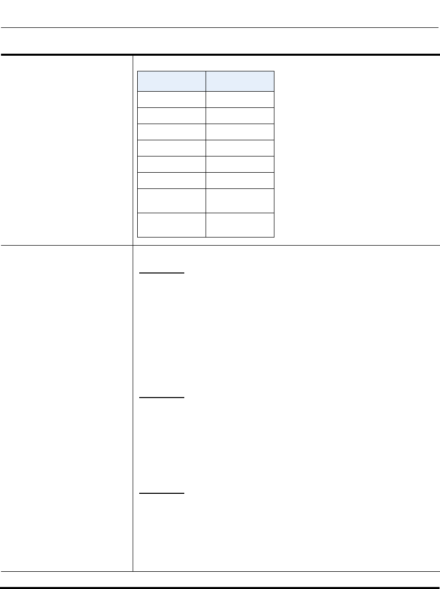
Troubleshooting Parameters
A-246 41-001160-03, Rev 00, Release 2.4
IP Phone Administrator Guide
Range
Examples Enter a debug level value in the “Debug Level” field for a module.
Example 1
To turn two or more debug levels on at the same time, you add the value
associated with each level. For example,
Fatal Errors + Errors + Warnings = 1 + 2 + 4 = 7
log module linemgr: 7
log module user interface: 7
log module sip: 7
In the above example, fatal errors, general errors, and warnings are
logged for the line manager, user interface, and SIP call control modules.
Example 2
Functions and Info = 16 + 32 = 48
log module dis: 48
log module net: 48
log module snd: 48
In the above example, functions and general information are logged for
the display drivers, network, and sound modules.
Example 3
log module rtpt: 0
log module ind: 65535
In the above example, all debug levels are OFF for the Real Time
Transport module. All debug levels are ON for the indicator module.
You can set the Module/Debug Levels using the configuration files or the
Aastra Web UI.
Debug Level Value
Fatal Errors 1 (default)
Errors 2
Warnings 4
Init 8
Functions 16
Info 32
All debug
levels OFF 0
All Debug
Levels ON 65535
Draft 1

Troubleshooting Parameters
41-001160-03, Rev 00, Release 2.4 A-247
WatchDog Settings
Parameter–
watchdog enable
WatchDog
(in Web UI)
Configuration Files aastra.cfg, <mac>.cfg
Aastra Web UI Advanced Settings->Troubleshooting
Description Enables/disables the use of the WatchDog task for the IP Phones.
Format Boolean
Default Value 1 (enabled)
Range 0 (disabled)
1 (enabled)
Example watchdog enable: 0
Draft 1

Troubleshooting Parameters
A-248 41-001160-03, Rev 00, Release 2.4
IP Phone Administrator Guide
Draft 1
41-001160-03, Rev 00, Release 2.4 B-1
Appendix B
Configuring the IP Phone
at the Asterisk IP PBX
About this appendix
Introduction
This appendix describes how to setup a user’s phone with an extension to make
and receive calls using the Asterisk as the PBX.
Topics
This appendix covers the following topics:
Topic Page
IP Phone at the Asterisk IP PBX page B-2
Draft 1

IP Phone at the Asterisk IP PBX
C-2 41-001160-03, Rev 00, Release 2.4
IP Phone Administrator Guide
IP Phone at the Asterisk IP PBX
The following configuration illustrates how to create a user with an extension to
make and receive calls using the Asterisk as the PBX. This configuration is
defined in the sip.conf file present along with the other configuration files that are
created when Asterisk is installed. Usually, the configuration files can be found at
the /etc/asterisk directory.
;This is used in the “extensions.conf” file to identify this
;physical phone when issuing Dial commands.
[phone1]
;The type to use for the 6757i is “friend”.
;”Peer” is used when the Asterisk is contacting a proxy,
;”user” is used for phones that can only make calls
;and “friend” acts as both a peer and a user.
type=friend
;If your host has an entry in your DNS then you just enter the
;machines name in the host= field.
host=dynamic
defaultip=192.168.1.1 ;default IP address that the phone is
;configured to
;The password that phone1 will use to register with this PBX
secret=1234
dtmfmode=rfc2833;Choices are inband, rfc2833, or info
mailbox=1000 ;Mailbox for message waiting indicator
;If a phone is not in a valid context you will not be
Draft 1

IP Phone at the Asterisk IP PBX
41-001160-03, Rev 00, Release 2.4 C-3
;able to use it. In this example' sip' is used. You can use
;whatever you like, but make sure they are the same, you will
;need to make an entry in your extensions.conf file (which we
;will get to later)
context=sip
callerid="Phone 1" <1234>
After this is defined in the “sip.conf” file, some information has to be entered in
the “extensions.conf” file present in the same directory as the “sip.conf” file. The
following definition in the file under the [sip]section/context completes defining
the extension for the 6757i phone.
This definition completes configuring the 6757i phone at the IP PBX system.
To verify whether the extension has been successfully registered at the IP PBX
system, enter the Asterisk console and reload Asterisk. Use the command “sip
show peers” at the console. This will display the extensions that are registered at
the IP PBX system.
This completes the basic set-up for the 6757i phone with 1234 extension at
the Asterisk IP PBX system. Refer to Asterisk documentation for set-up on
extended or advanced features such as voice mail and call forwarding, etc.
Table 1:
exten -> 1234,1,Dial(SIP/phone1,20)
Table 2:
Name/username Host Mask Port Status
phone1/phone1192.168.1.1 (D) 255.255.255.255 5060
Unmonitored
Draft 1
Draft 1
41-001160-03, Rev 00, Release 2.4 C-1
Appendix C
Sample Configuration Files
About this appendix
Introduction
This appendix provides sample configuration files for the 6757i, 6757i CT, and
6753i.
Topics
This appendix covers the following topics:
Topic Page
Sample Configuration Files page C-2
6757i Sample Configuration File page C-2
6757i CT Sample Configuration File page C-12
6753i Sample Configuration File page C-29
Draft 1

Sample Configuration Files
C-2 41-001160-03, Rev 00, Release 2.4
IP Phone Administrator Guide
Sample Configuration Files
This section consists of the sample configuration files necessary to configure the
IP phones. The general format is similar to configuration files used by several
Unix-based programs. Any text following a number sign (#) on a line is
considered to be a comment, unless the # is contained within
double-quotes. Currently, Boolean fields use 0 for false and 1 for true.
6757i Sample Configuration File
# Sample Configuration File
# ===========================
# Date: October 20th, 2005
# Phone Model: 6757i
# Notes:
#
# The general format used here is similar to configuration files
# used by several UNIX-based programs. Any text following a number
# sign (#) is considered to be a comment, unless the number sign is
# contained within double-quotes ("#") where it is considered to be
# a pound. For Boolean fields, 0 = false, 1 = true.
# Comments:
#
# This file contains sample configurations for the "aastra.cfg" or
# "<mac>.cfg" file. The settings included here are examples only.
# You should change/comment the values to suit your requirements.
#
# Not all possible paramters are shown, refer to the admin guide for
# the full list of supported parameters, their defaults and valid
# ranges.
#
Draft 1

Sample Configuration Files
41-001160-03, Rev 00, Release 2.4 C-3
# The Aastra 6757i, 6757iCT, and 6753i phones will download 2
# configuration files from the TFTP server while restarting, the
# "aastra.cfg" file and the "<mac>.cfg" file. These two configuration
# files can be used to configure all of the settings of the phone with
# the exception of assigning a static IP address to a phone and line
# settings, which should only be set in the "<mac>.cfg" file.
#
# The "aastra.cfg" file configures the settings server wide, while
# the "<mac>.cfg" file configures only the phone with the MAC address
# for which the file is named (for example, "00085d0304f4.cfg"). The
# settings in the "aastra.cfg" file will be overridden by settings
# which also appear in the "<mac>.cfg" file.
#------------------------------------------------------------------
# DHCP Setting
# ==============
#dhcp: 1 # DHCP enabled.
# DHCP:
# 0 = false, means DHCP is disabled.
# 1 = true, means DHCP is enabled.
#
# Notes:
#
# DHCP is normally set from the Options list on the phone or
# the web interface
#
# If DHCP is disabled, the following network settings will
# have to be configured manually either through the configuration
# files, the Options List in the phone, or the Web Client: IP
# Address (of the phone), Subnet Mask, Gateway, DNS, and TFTP
# Server.
#-------------------------------------------------------------------
Draft 1

Sample Configuration Files
C-4 41-001160-03, Rev 00, Release 2.4
IP Phone Administrator Guide
# Network Settings
## = = = = = = = =
# Notes: If DHCP is enabled, you do not need to set these network
# settings. Although depending on you DHCP server configuration you
# may still have to set the dns address.
#ip: # This value is unique to each phone on a server
# and should be set in the "<mac>.cfg" file if
# setting this manually.
#subnet mask:
#default gateway:
#dns1:
#dns2:
# Time Server Settings
## =====================
#time server disabled: 1 # Time server disabled.
#time server1: # Enable time server and enter at
#time server2: # least one time server IP address or
#time server3: # qualified domain name
# Time Server Disabled:
# 0 = false, means the time server is not disabled.
# 1 = true, means the time server is disabled.
# NAT Settings
# ===============
# Option 1:
#
# If you are connecting to a Nortel MCS call server and there is a
Draft 1

Sample Configuration Files
41-001160-03, Rev 00, Release 2.4 C-5
# NAT device between the server and the phone, then you must set the
# following two parameters for the phone to function correctly.
#sip nortel nat support: 1 # 1 = enabled
#sip nortel nat timer: 60 # seconds between keep alive messages
# Option 2:
#
# If you are using a session border controller, you should set the
# outbound proxy to the session border controller address
#sip outbound proxy: sbc.aastra.com
#sip outbound proxy port: 0 # a value of 0 enables SRV
# lookups for the address of
# the proxy.
# Option 3:
#
# If you know the public IP address of your NAT device and and have
# opened up a port for the SIP messages then you can statically
# assign this information.
#sip nat ip: 67.123.122.90
#sip nat port: 5890
# Additional Network Settings
# =============================
#sip rtp port: 3000 # Eg. RTP packets are sent to port 3000.
#-------------------------------------------------------------------
# Configuration Server Settings
Draft 1

Sample Configuration Files
C-6 41-001160-03, Rev 00, Release 2.4
IP Phone Administrator Guide
## = = = = = = = = = = = = = = =
# Notes: This section defines which server the phone retrieves new
# firmware images and configuration files from. Three protocols are
# supported TFTP, FTP and HTTP
download protocol: TFTP # valid values are TFTP, FTP and HTTP
## TFTP server settings
tftp server: 192.168.0.130
#alternate tftp server:
#use alternate tftp server: 1 # If your DHCP server assigns
# a TFTP server address which
# you do not use, you can use
# the alternate tftp server.
## FTP server settings
#ftp server: 192.168.0.131 # can be IP or FQDN
#ftp username: aastra
#ftp password: 6757iaastra
## HTTP server settings (for http://bogus.aastra.com/firmware/)
#http server: bogus.aastra.com # can be IP or FQDN
#http path: firmware
#-------------------------------------------------------------------
# Dial Plan Settings
# =====================
#
# Notes:
#
# As you dial a number on the phone, the phone will initiate a call
# when one of the following conditions are meet:
Draft 1

Sample Configuration Files
41-001160-03, Rev 00, Release 2.4 C-7
#
# (1) The entered number is an exact match in the dial plan
# (2) The "#" symbol has been pressed
# (3) A timeout occurs
#
# The dial plan is a regular expression that supports the following
# syntax:
#
# 0,1,2,3,4,5,6,7,8,9,*,# : matches the keypad symbols
# x : matches any digit (0...9)
# + : matches 0 or more repetitions of the
# : previous expression
# [] : matches any number inside the brackets
# : can be used with a "-" to represent a
# : range
# () : expression grouping
# | : either or
#
#
# If the dialled number doesn't match the dial plan then the call
# is rejected.
sip digit timeout: 3 # set the inter-digit timeout in seconds
# Example dial plans
sip dial plan: "x+#|xx+*" # this is the default dial string, note
# that is must be quoted since it contains
# a '#' character
#sip dial plan: [01]xxx|[2-8]xxxx|91xxxxxxxxxx
# accecpt any 4 digit number beginning
# with a 0 or 1, any 5 digit number
# beginning with a number between 2 and 8
# (inclusive) or a 12 digit number
# beginning with 91
Draft 1

Sample Configuration Files
C-8 41-001160-03, Rev 00, Release 2.4
IP Phone Administrator Guide
#sip dial plan terminator: 1 # enable sending of the "#" symbol to
# to the proxy in the dial string
#------------------------------------------------------------------
# General SIP Settings
# = = = = = = = = = = =
#sip session timer: 30 # enable support of RFC4028, the default
# value of 0 disables this functionality
#sip transport protocol: 0 # use UDP (1), TCP (2) or both (0) for sip
# messaging
#sip use basic codecs: 1 # limit codecs to G711 and G729
#sip out-of-band dtmf: 0 # turn off support for RFC2833 (on by
# default)
# Global SIP User Settings
# ==========================
#
# Notes:
# These settings are used as the default configuration for the hard
# key lines on the phone. That is:
#
# L1 to L4 on the 6757i and 6757iCT
# L1 to L3 on the 6753i
#
# These can be over-ridden on a per-line basis using the per-line
# settings.
#
# See the Admin Guide for a detailed explaination of how this works
Draft 1

Sample Configuration Files
41-001160-03, Rev 00, Release 2.4 C-9
sip screen name: Joe Smith # the name display on the phone's screen
sip user name: 4256 # the phone number
sip display name: Joseph Smith # the caller name sent out when making
# a call.
sip vmail: *78 # the number to reach voicemail on
sip auth name: jsmith # account used to authenticate user
sip password: 12345 # password for authentication account
sip mode: 0 # line type:
# 0 - generic,
# 1 - BroadSoft SCA line
# 2 - Nortel line
sip proxy ip: proxy.aastra.com # IP address or FQDN of proxy
sip proxy port: 5060 # port used for SIP messages on the
# proxy. Set to 0 to enable SRV
# lookups
sip registrar ip: aastra.com # IP address or FQDN of registrar
sip registrar port: 0 # as proxy port, but for the registrar
sip registration period: 3600 # registration period in seconds
# Per-line SIP Settings
# ======================
# configure line 3 as the support Broadsoft SCA line
# - the proxy and registrar settings are taken from the global
# settings above
sip line3 screen name: Support
sip line3 user name: 4000
sip line3 display name: Aastra Support
sip line3 auth name: support
sip line3 password: 54321
sip line3 mode: 1
Draft 1

Sample Configuration Files
C-10 41-001160-03, Rev 00, Release 2.4
IP Phone Administrator Guide
sip line3 vmail: *78
# configure line 5 (a soft key line) as an ordinary line
# of a test server
sip line5 screen name: Test 1
sip line5 user name: 5551001
sip line5 display name: Test 1
sip line5 auth name: 5551001
sip line5 password: 5551001
sip line5 mode: 0
sip line5 proxy ip: 10.50.10.102
sip line5 proxy port: 5060
sip line5 registrar ip: 10.50.10.102
sip line5 registrar port: 5060
sip line5 registration period: 60
#-------------------------------------------------------------------
# Softkey Settings
#
# Softkeys can be set either server wide or unique to each phone.
# Setting softkeys as line/call appearances should be done in the
# "<mac>.cfg" file, since these are unique to each phone.
# Notes:
#
# There are a maximum of 18 softkeys that can be configured on the
# 6757i or 6757iCT phone. These can be set up through either of the 2
# configuration files, depending on whether this is to be server wide
# ("aastra.cfg") or phone specific ("<mac>.cfg"). Each softkey needs
# to be numbered from 1 - 18, for example "softkey12 type:
# speeddial". Softkeys can be set up as speeddials or as additional
# call/line appearances and have a type, label and value associated
Draft 1

Sample Configuration Files
41-001160-03, Rev 00, Release 2.4 C-11
# with it as seen here in the default softkey settings.
# SOFTKEY TYPES: "line", "speeddial", "blf", "list", "dnd"
# SOFTKEY LABEL: Alpha numeric name for the softkey. The maximum
# number of characters for this value is 10 for
# speeddials and dnd, 9 chars for lines, blf
# SOFTKEY VALUE: If softkey type is a speeddial, any DTMFs (from
# 0 - 9, *, "#") or a comma (,) for 500ms pause and
# 'E' for On-hook can be set for the value.
# If softkey type is blf it is the extension you want
# to monitor.
# SOFTKEY LINE: This is line associated with the softkey. For line
# softkeys the value must be between 5 and 9 (1 - 4
# are already hardcoded as the L1, L2, L3 and L4 hard
# key line/call appearances)
# Speed Dials
softkey1 type: speeddial
softkey1 label: "Ext Pickup"
softkey1 value: *8
softkey2 type: speeddial
softkey2 label: "Call Return"
softkey2 value: *69
# DND Key
softkey4 type: dnd
softkey4 label: DND
# Line appearance
softkey6 type: line
softkey6 label: Test 1
softkey6 line: 5
# blf
softkey8 type: blf
softkey8 label: Jane Doe
softkey8 value: 4559
Draft 1

Sample Configuration Files
C-12 41-001160-03, Rev 00, Release 2.4
IP Phone Administrator Guide
softkey8 line: 1
# list
softkey11 type: list
softkey12 type: list
6757i CT Sample Configuration File
# Sample Configuration File
# =========================
# Date: October 26th, 2005
# Phone Model: 6757iCT
# Notes:
#
# The general format used here is similar to configuration files
# used by several UNIX-based programs. Any text following a number
# sign (#) is considered to be a comment, unless the number sign is
# contained within double-quotes ("#") where it is considered to be
# a pound. For Boolean fields, 0 = false, 1 = true.
# Comments:
#
# This file contains sample configurations for the "aastra.cfg" or
# "<mac>.cfg" file. The settings included here are examples only.
# You should change/comment the values to suit your requirements.
#
# Not all possible paramters are shown, refer to the admin guide for
# the full list of supported parameters, their defaults and valid
# ranges.
#
# The Aastra 6757i, 6757iCT, and 6753i phones will download 2
# configuration files from the TFTP server while restarting, the
Draft 1

Sample Configuration Files
41-001160-03, Rev 00, Release 2.4 C-13
# "aastra.cfg" file and the "<mac>.cfg" file. These two configuration
# files can be used to configure all of the settings of the phone with
# the exception of assigning a static IP address to a phone and line
# settings, which should only be set in the "<mac>.cfg" file.
#
# The "aastra.cfg" file configures the settings server wide, while the
# "<mac>.cfg" file configures only the phone with the MAC address for
# which the file is named (for example, "00085d0304f4.cfg"). The
# settings in the "aastra.cfg" file will be overridden by settings
# which also appear in the "<mac>.cfg" file.
#-------------------------------------------------------------------
# DHCP Setting
# ============
#dhcp: 1 # DHCP enabled.
# DHCP:
# 0 = false, means DHCP is disabled.
# 1 = true, means DHCP is enabled.
#
# Notes:
#
# DHCP is normally set from the Options list on the phone or
# the web interface
#
# If DHCP is disabled, the following network settings will
# have to be configured manually either through the configuration
# files, the Options List in the phone, or the Web Client: IP
# Address (of the phone), Subnet Mask, Gateway, DNS, and TFTP
# Server.
#-------------------------------------------------------------------
Draft 1

Sample Configuration Files
C-14 41-001160-03, Rev 00, Release 2.4
IP Phone Administrator Guide
# Network Settings
# ================
# Notes: If DHCP is enabled, you do not need to set these network
# settings. Although depending on you DHCP server configuration you
# may still have to set the dns address.
Draft 1

Sample Configuration Files
41-001160-03, Rev 00, Release 2.4 C-15
#ip: # This value is unique to each phone on a server
# and should be set in the "<mac>.cfg" file if
# setting this manually.
#subnet mask:
#default gateway:
#dns1:
#dns2:
# Time Server Settings
# ====================
#time server disabled: 1 # Time server disabled.
#time server1: # Enable time server and enter at
#time server2: # least one time server IP address or
#time server3: # qualified domain name
# Time Server Disabled:
# 0 = false, means the time server is not disabled.
# 1 = true, means the time server is disabled.
# NAT Settings
#=============
# Option 1:
#
# If you are connecting to a Nortel MCS call server and there is a
# NAT device between the server and the phone, then you must set the
# following two parameters for the phone to function correctly.
#sip nortel nat support: 1 # 1 = enabled
Draft 1

Sample Configuration Files
C-16 41-001160-03, Rev 00, Release 2.4
IP Phone Administrator Guide
#sip nortel nat timer: 60 # seconds between keep alive messages
# Option 2:
#
# If you are using a session border controller, you should set the
# outbound proxy to the session border controller address
#sip outbound proxy: sbc.aastra.com
#sip outbound proxy port: 0 # a value of 0 enables SRV
# lookups for the address of
# the proxy.
# Option 3:
#
# If you know the public IP address of your NAT device and and have
# opened up a port for the SIP messages then you can statically
# assign this information.
#sip nat ip: 67.123.122.90
#sip nat port: 5890
# Additional Network Settings
#============================
#sip rtp port: 3000 # Eg. RTP packets are sent to port 3000.
#------------------------------------------------------------------
# Configuration Server Settings
# =============================
Draft 1

Sample Configuration Files
41-001160-03, Rev 00, Release 2.4 C-17
# Notes: This section defines which server the phone retrieves new
# firmware images and configuration files from. Three protocols are
# supported TFTP, FTP and HTTP
download protocol: TFTP # valid values are TFTP, FTP and HTTP
## TFTP server settings
tftp server: 192.168.0.130
#alternate tftp server:
#use alternate tftp server: 1 # If your DHCP server assigns
# a TFTP server address which
# you do not use, you can use
# the alternate tftp server.
## FTP server settings
#ftp server: 192.168.0.131 # can be IP or FQDN
#ftp username: aastra
#ftp password: 6757iaastra
## HTTP server settings (for http://bogus.aastra.com/firmware/)
#http server: bogus.aastra.com # can be IP or FQDN
#http path: firmware
#------------------------------------------------------------------
# Dial Plan Settings
# ==================
#
# Notes:
#
Draft 1

Sample Configuration Files
C-18 41-001160-03, Rev 00, Release 2.4
IP Phone Administrator Guide
# As you dial a number on the phone, the phone will initiate a call
# when one of the following conditions are meet:
#
# (1) The entered number is an exact match in the dial plan
# (2) The "#" symbol has been pressed
# (3) A timeout occurs
#
# The dial plan is a regular expression that supports the following
# syntax:
#
# 0,1,2,3,4,5,6,7,8,9,*,# : matches the keypad symbols
# x : matches any digit (0...9)
# + : matches 0 or more repetitions of the
# : previous expression
# [] : matches any number inside the brackets
# : can be used with a "-" to represent a
# : range
# () : expression grouping
# | : either or
#
#
# If the dialled number doesn't match the dial plan then the call
# is rejected.
sip digit timeout: 3 # set the inter-digit timeout in seconds
# Example dial plans
sip dial plan: "x+#|xx+*" # this is the default dial string, note
# that is must be quoted since it contains
# a '#' character
#sip dial plan: [01]xxx|[2-8]xxxx|91xxxxxxxxxx
# accecpt any 4 digit number beginning
Draft 1

Sample Configuration Files
41-001160-03, Rev 00, Release 2.4 C-19
# with a 0 or 1, any 5 digit number
# beginning with a number between 2 and 8
# (inclusive) or a 12 digit number
# beginning with 91
#sip dial plan terminator: 1 # enable sending of the "#" symbol to
# to the proxy in the dial string
#-------------------------------------------------------------------
# General SIP Settings
# ====================
#sip session timer: 30 # enable support of RFC4028, the default
# value of 0 disables this functionality
#sip transport protocol: 0 # use UDP (1), TCP (2) or both (0) for sip
# messaging
#sip use basic codecs: 1 # limit codecs to G711 and G729
#sip out-of-band dtmf: 0 # turn off support for RFC2833 (on by
# default)
# Global SIP User Settings
# ========================
#
# Notes:
# These settings are used as the default configuration for the hard
# key lines on the phone. That is:
#
Draft 1

Sample Configuration Files
C-20 41-001160-03, Rev 00, Release 2.4
IP Phone Administrator Guide
# L1 to L4 on the 6757i and 6757iCT
# L1 to L3 on the 6753i
#
# These can be over-ridden on a per-line basis using the per-line
# settings.
#
# See the Admin Guide for a detailed explaination of how this works
sip screen name: Joe Smith # the name display on the phone's screen
sip user name: 4256 # the phone number
sip display name: Joseph Smith # the caller name sent out when making
# a call.
sip vmail: *78 # the number to reach voicemail on
sip auth name: jsmith # account used to authenticate user
sip password: 12345 # password for authentication account
sip mode: 0 # line type:
# 0 - generic,
# 1 - BroadSoft SCA line
# 2 - Nortel line
sip proxy ip: proxy.aastra.com # IP address or FQDN of proxy
sip proxy port: 5060 # port used for SIP messages on the
# proxy. Set to 0 to enable SRV
# lookups
sip registrar ip: aastra.com # IP address or FQDN of registrar
sip registrar port: 0 # as proxy port, but for the registrar
sip registration period: 3600 # registration period in seconds
# Per-line SIP Settings
# =====================
Draft 1

Sample Configuration Files
41-001160-03, Rev 00, Release 2.4 C-21
# configure line 3 as the support Broadsoft SCA line
# - the proxy and registrar settings are taken from the global
# settings above
sip line3 screen name: Support
sip line3 user name: 4000
sip line3 display name: Aastra Support
sip line3 auth name: support
sip line3 password: 54321
sip line3 mode: 1
sip line3 vmail: *78
# configure line 5 (a soft key line) as an ordinary line
# of a test server
sip line5 screen name: Test 1
sip line5 user name: 5551001
sip line5 display name: Test 1
sip line5 auth name: 5551001
sip line5 password: 5551001
sip line5 mode: 0
sip line5 proxy ip: 10.50.10.102
sip line5 proxy port: 5060
sip line5 registrar ip: 10.50.10.102
sip line5 registrar port: 5060
sip line5 registration period: 60
#-------------------------------------------------------------------
# Softkey Settings
# ================
Draft 1

Sample Configuration Files
C-22 41-001160-03, Rev 00, Release 2.4
IP Phone Administrator Guide
# Softkeys can be set either server wide or unique to each phone.
# Setting softkeys as line/call appearances should be done in the
# "<mac>.cfg" file, since these are unique to each phone.
# Notes:
#
# There are a maximum of 18 softkeys that can be configured on the
# 6757i or 6757iCT phone. These can be set up through either of the 2
# configuration files, depending on whether this is to be server wide
# ("aastra.cfg") or phone specific ("<mac>.cfg"). Each softkey needs
# to be numbered from 1 - 18, for example "softkey12 type:
# speeddial". Softkeys can be set up as speeddials or as additional
# call/line appearances and have a type, label and value associated
# with it as seen here in the default softkey settings.
# SOFTKEY TYPES: "line", "speeddial", "blf", "list", "dnd"
# SOFTKEY LABEL: Alpha numeric name for the softkey. The maximum
# number of characters for this value is 10 for
# speeddials and dnd, 9 chars for lines, blf
# SOFTKEY VALUE: If softkey type is a speeddial, any DTMFs (from
# 0 - 9, *, "#") or a comma (,) for 500ms pause and
# 'E' for On-hook can be set for the value.
# If softkey type is blf it is the extension you want
# to monitor.
# SOFTKEY LINE: This is line associated with the softkey. For line
# softkeys the value must be between 5 and 9 (1 - 4
# are already hardcoded as the L1, L2, L3 and L4 hard
# key line/call appearances)
# Speed Dials
softkey1 type: speeddial
softkey1 label: "Ext Pickup"
softkey1 value: *8
Draft 1

Sample Configuration Files
41-001160-03, Rev 00, Release 2.4 C-23
softkey2 type: speeddial
softkey2 label: "Call Return"
softkey2 value: *69
# DND Key
softkey4 type: dnd
softkey4 label: DND
# Line appearance
softkey6 type: line
softkey6 label: Test 1
softkey6 line: 5
# blf
softkey8 type: blf
softkey8 label: Jane Doe
softkey8 value: 4559
softkey8 line: 1
# list
softkey11 type: list
softkey12 type: list
#-------------------------------------------------------------------
# Cordless Handset Feature Keys
# =============================
# Notes:
#
# In addition to the configuration parameters that exist on the 6757i
# phone, following are the parameters specific to the 6757i Cordless
# phones' handset. These parameters can be defined either int the
Draft 1

Sample Configuration Files
C-24 41-001160-03, Rev 00, Release 2.4
IP Phone Administrator Guide
# aastra.cfg or the <mac>.cfg files.
#
# The feature keys are displayed when the user presses the F button
# on the cordless phone's hand set. If any changes to the features
# keys are made using these parameters the feature keys that exist on
# the hand set have to be refreshed. To refresh the feature keys
# simply open a new line or press one of the feature keys that are
# available from the hand set. After a couple of seconds the cordless
# should get the new list from the base set. There are 15 feature
# keys that can be configured for the cordless hand set. Each feature
# key has the following settings. N corresponds to the feature key
# that is being configured for and ranges from 0-14. Feature key N
# En label: "String" Feature key N Fr label: "Fr-String" Feature key
# N Sp label: "Sp-String" Feature key N control: 1 #Takes an
# integer value Feature key N hs event: 1 #Takes an integer value
# Feature key N base event: 1 #Takes an integer value
#key list version: 1
# The parameter value has to be incremented by one whenever the
# parameters that carry the feature keys change. The range is from
# 1-254. After reaching 254 start over from 1.
#Feature key 0 En label: "Line 1"
# English label for the key. Displayed when the phone's language is
# set to use English
#Feature key 0 Fr label: "Fr-Line 1"
# French label for the key. Displayed when the phone's language
# is set to use French
#Feature key 0 Sp label: "Sp-Line 1"
# Spanish label for the key. Displayed when the phone's language
# is set to use Spanish
Draft 1

Sample Configuration Files
41-001160-03, Rev 00, Release 2.4 C-25
Feature key 0 Gr label: "Gr-Line 1"
# German label for the key. Displayed when the phone's language
# is set to use German
Feature key 0 It label: "It-Line 1"
# Italian label for the key. Displayed when the phone's language
# is set to use Italian
#Feature key 0 control: 1
# 1 - Make the key configurable by the user through the phone and
# the phone's web client
# 2 - Locks the key from user modifications. User cannot modify
# this key from the handset or the phone's web client.
# 4 - Hide this key. Do not show it in the Feature keys list in the
# cordless handset
# 6 - Lock and hide this key. Do not show it in the Feature keys
# list in the cordless handset and do not let the user modify
# this key using the phone or the web client.
#Feature key 0 hs event: 7
# These events are for handset specific events. Events can be local
# to the handset like directory/caller's list, intercom etc. or may
# be an event that is sent to the base set for fruther processing.
# When this key is configured as a base event then the base set
# will process the value of this key in conjunction with the value
# configured for the "Feature key N base event". Where N is the
# feature key is being configured for.
# In addition to the values listed below the valid values are
# [7-23]. The values [7-23] indicate generic handset events. If
# you are using values within this range make sure to use the value
# only once.
# The events local to the handset are as follows:
#
Draft 1

Sample Configuration Files
C-26 41-001160-03, Rev 00, Release 2.4
IP Phone Administrator Guide
# 58 - Menu (Options)
# 59 - Feature Key
# 60 - Redial
# 61 - Directory
# 62 - Callers' list
# 63 - Services
# 86 - Icom
#Feature key 0 base event: 1
# Indicates a corresponding action to perform on the base set when
# the "Feature key N hs event" is set to any value between 7-23.
#
# 1 - Seize base set's line1
# 2 - Seize base set's line2
# 3 - Seize base set's line3
# 4 - Seize base set's line4
# 5 - Seize base set's line5
# 6 - Seize base set's line6
# 7 - Seize base set's line7
# 8 - Seize base set's line8
# 9 - Seize base set's line9
# 10 - Seize base set's line0
# 11 - Send the base set's transfer event
# 12 - Send the base set's conference event
# 13 - Make feature list public
# Example configuration
key list version: 1
Feature key 0 En label: "Line 1"
Feature key 0 Fr label: "Fr-Line 1"
Feature key 0 Sp label: "Sp-Line 1"
Feature key 0 control: 0
Draft 1

Sample Configuration Files
41-001160-03, Rev 00, Release 2.4 C-27
Feature key 0 hs event: 7
Feature key 0 base event: 1
Feature key 1 En label: "Conf."
Feature key 1 Fr label: "Fr-Conf."
Feature key 1 Sp label: "Sp-Conf."
Feature key 1 control: 1
Feature key 1 hs event: 8
Feature key 1 base event: 12
Feature key 2 En label: "Xfer"
Feature key 2 Fr label: "Fr-Xfer."
Feature key 2 Sp label: "Sp-Xfer."
Feature key 2 control: 2
Feature key 2 hs event: 9
Feature key 2 base event: 11
Feature key 3 En label: "Icom"
Feature key 3 Fr label: "Fr-Icom"
Feature key 3 Sp label: "Sp-Icom"
Feature key 3 control: 1
Feature key 3 hs event: 86
Feature key 3 base event: 13
Feature key 4 En label: "Opt"
Feature key 4 Fr label: "Fr-Opt"
Feature key 4 Sp label: "Sp-Opt"
Feature key 4 hs event: 58
Feature key 4 control: 1
Feature key 4 base event: 13
Feature key 5 En label: "Callers"
Feature key 5 Fr label: "Fr-Callers"
Feature key 5 Sp label: "Sp-Callers"
Draft 1

Sample Configuration Files
C-28 41-001160-03, Rev 00, Release 2.4
IP Phone Administrator Guide
Feature key 5 hs event: 62
Feature key 5 control: 1
Feature key 5 base event: 13
Feature key 6 En label: "Top"
Feature key 6 Fr label: "Fr-Top"
Feature key 6 Sp label: "Sp-Top"
Feature key 6 hs event: 17
Feature key 6 control: 1
Feature key 6 base event: 13
Feature key 7 En label: "Redial"
Feature key 7 Fr label: "Fr-Redial"
Feature key 7 Sp label: "Sp-Redial"
Feature key 7 hs event: 60
Feature key 7 control: 4
Feature key 7 base event: 13
Feature key 8 En label: "Dir."
Feature key 8 Fr label: "Fr-Dir."
Feature key 8 Sp label: "Sp-Dir."
Feature key 8 hs event: 61
Feature key 8 control: 2
Feature key 8 base event: 13
Feature key 9 En label: "Services"
Feature key 9 Fr label: "Fr-Services"
Feature key 9 Sp label: "Sp-Services"
Feature key 9 hs event: 63
Feature key 9 control: 1
Feature key 9 base event: 13
Draft 1

Sample Configuration Files
41-001160-03, Rev 00, Release 2.4 C-29
6753i Sample Configuration File
# Sample Configuration File
#= = = = = = = = = = = = = = = = = = = = =
# Date: October 26th, 2005
# Phone Model: 6753i
# Notes:
#
# The general format used here is similar to configuration files
# used by several UNIX-based programs. Any text following a number
# sign (#) is considered to be a comment, unless the number sign is
# contained within double-quotes ("#") where it is considered to be
# a pound. For Boolean fields, 0 = false, 1 = true.
# Comments:
#
# This file contains sample configurations for the "aastra.cfg" or
# "<mac>.cfg" file. The settings included here are examples only.
# You should change/comment the values to suit your requirements.
#
# Not all possible paramters are shown, refer to the admin guide
# for the full list of supported parameters, their defaults and
# valid ranges.
#
# The Aastra 6757i, 6757iCT, and 6753i phones will download 2
# configuration files from the TFTP server while restarting, the
# "aastra.cfg" file and the "<mac>.cfg" file. These two
# configuration files can be used to configure all of the settings
# of the phone with the exception of assigning a static IP address
# to a phone and line settings, which should only be set in the "<mac>.cfg" file.
#
Draft 1

Sample Configuration Files
C-30 41-001160-03, Rev 00, Release 2.4
IP Phone Administrator Guide
# The "aastra.cfg" file configures the settings server wide, while
# the "<mac>.cfg" file configures only the phone with the MAC
# address for which the file is named (for example,
# "00085d0304f4.cfg"). The settings in the "aastra.cfg" file will
# be overridden by settings which also appear in the "<mac>.cfg" file.
#-----------------------------------------------------------------
# DHCP Setting
# =============
#dhcp: 1 # DHCP enabled.
# DHCP:
# 0 = false, means DHCP is disabled.
# 1 = true, means DHCP is enabled.
#
# Notes:
#
# DHCP is normally set from the Options list on the phone or
# the web interface
#
# If DHCP is disabled, the following network settings will
# have to be configured manually either through the configuration
# files, the Options List in the phone, or the Web Client: IP
# Address (of the phone), Subnet Mask, Gateway, DNS, and TFTP
# Server.
#-----------------------------------------------------------------
# Network Settings
# = = = = = = = = =
# Notes: If DHCP is enabled, you do not need to set these network
# settings. Although depending on you DHCP server configuration
# you may still have to set the dns address.
Draft 1

Sample Configuration Files
41-001160-03, Rev 00, Release 2.4 C-31
#ip: # This value is unique to each phone on a server
# and should be set in the "<mac>.cfg" file if
# setting this manually.
#subnet mask:
#default gateway:
#dns1:
#dns2:
# Time Server Settings
# =====================
#time server disabled: 1 # Time server disabled.
#time server1: # Enable time server and enter at
#time server2: # least one time server IP address or
#time server3: # qualified domain name.
# Time Server Disabled:
# 0 = false, means the time server is not disabled.
# 1 = true, means the time server is disabled.
# NAT Settings
# = = = = = = =
# Option 1:
#
# If you are connecting to a Nortel MCS call server and there is a
# NAT device between the server and the phone, then you must set
# the following two parameters for the phone to function
# correctly.
#sip nortel nat support: 1 # 1 = enabled
Draft 1

Sample Configuration Files
C-32 41-001160-03, Rev 00, Release 2.4
IP Phone Administrator Guide
#sip nortel nat timer: 60 # seconds between keep alive messages
Draft 1

Sample Configuration Files
41-001160-03, Rev 00, Release 2.4 C-33
# Option 2:
#
# If you are using a session border controller, you should set the
# outbound proxy to the session border controller address
#sip outbound proxy: sbc.aastra.com
#sip outbound proxy port: 0 # a value of 0 enables SRV
# lookups for the address of
# the proxy.
# Option 3:
#
# If you know the public IP address of your NAT device and and have
# opened up a port for the SIP messages then you can statically
# assign this information.
#sip nat ip: 67.123.122.90
#sip nat port: 5890
# Additional Network Settings
# ============================
#sip rtp port: 3000 # Eg. RTP packets are sent to port 3000.
#-----------------------------------------------------------------
# Configuration Server Settings
# = = = = = = = = = = = = = =
# Notes: This section defines which server the phone retrieves new
# firmware images and configuration files from. Three protocols
# are supported TFTP, FTP and HTTP
download protocol: TFTP # valid values are TFTP, FTP and HTTP
Draft 1

Sample Configuration Files
C-34 41-001160-03, Rev 00, Release 2.4
IP Phone Administrator Guide
Draft 1

Sample Configuration Files
41-001160-03, Rev 00, Release 2.4 C-35
## TFTP server settings
tftp server: 192.168.0.130
#alternate tftp server:
#use alternate tftp server: 1 # If your DHCP server assigns
# a TFTP server address which
# you do not use, you can use
# the alternate tftp server.
## FTP server settings
#ftp server: 192.168.0.131 # can be IP or FQDN
#ftp username: aastra
#ftp password: 6757iaastra
## HTTP server settings (for http://bogus.aastra.com/firmware/)
#http server: bogus.aastra.com # can be IP or FQDN
#http path: firmware
#----------------------------------------------------------------
# Dial Plan Settings
# ====================
#
# Notes:
#
# As you dial a number on the phone, the phone will initiate a call
# when one of the following conditions are meet:
#
# (1) The entered number is an exact match in the dial plan
# (2) The "#" symbol has been pressed
# (3) A timeout occurs
#
# The dial plan is a regular expression that supports the
# following:
# syntax:
Draft 1

Sample Configuration Files
C-36 41-001160-03, Rev 00, Release 2.4
IP Phone Administrator Guide
#
Draft 1

Sample Configuration Files
41-001160-03, Rev 00, Release 2.4 C-37
# 0,1,2,3,4,5,6,7,8,9,*,# : matches the keypad symbols
# x : matches any digit (0...9)
# + : matches 0 or more repetitions of the
# : previous expression
# [] : matches any number inside the brackets
# : can be used with a "-" to represent a
# : range
# () : expression grouping
# | : either or
#
#
# If the dialled number doesn't match the dial plan then the call
# is rejected.
sip digit timeout: 3 # set the inter-digit timeout in seconds
# Example dial plans
sip dial plan: "x+#|xx+*" # this is the default dial string, note
# that is must be quoted since it contains
# a '#' character
#sip dial plan: [01]xxx|[2-8]xxxx|91xxxxxxxxxx
# accecpt any 4 digit number beginning
# with a 0 or 1, any 5 digit number
# beginning with a number between 2 and 8
# (inclusive) or a 12 digit number
# beginning with 91
#sip dial plan terminator: 1 # enable sending of the "#" symbol to
# to the proxy in the dial string
#-----------------------------------------------------------------
Draft 1

Sample Configuration Files
C-38 41-001160-03, Rev 00, Release 2.4
IP Phone Administrator Guide
# General SIP Settings
# ======================
#sip session timer: 30 # enable support of RFC4028, the default
# value of 0 disables this functionality
#sip transport protocol: 0 # use UDP (1), TCP (2) or both (0) for
# sip messaging
#sip use basic codecs: 1 # limit codecs to G711 and G729
#sip out-of-band dtmf: 0 # turn off support for RFC2833 (on by
# default)
# Global SIP User Settings
# ==========================
#
# Notes:
# These settings are used as the default configuration for the
# hard key lines on the phone. That is:
#
# L1 to L4 on the 6757i and 6757iCT
# L1 to L3 on the 6753i
#
# These can be over-ridden on a per-line basis using the per-line
# settings.
#
# See the Admin Guide for a detailed explaination of how this
# works
sip screen name: Joe Smith # the name display on the phone's screen
sip user name: 4256 # the phone number
sip display name: Joseph Smith # the caller name sent out when making
# a call.
sip vmail: *78 # the number to reach voicemail on
Draft 1

Sample Configuration Files
41-001160-03, Rev 00, Release 2.4 C-39
sip auth name: jsmith # account used to authenticate user
sip password: 12345 # password for authentication account
sip mode: 0 # line type:
# 0 - generic,
# 1 - BroadSoft SCA line
# 2 - Nortel line
sip proxy ip: proxy.aastra.com # IP address or FQDN of proxy
sip proxy port: 5060 # port used for SIP messages on the
# proxy. Set to 0 to enable SRV
# lookups
sip registrar ip: aastra.com # IP address or FQDN of registrar
sip registrar port: 0 # as proxy port, but for the registrar
sip registration period: 3600 # registration period in seconds
# Per-line SIP Settings
# =======================
# configure line 3 as the support Broadsoft SCA line
# - the proxy and registrar settings are taken from the global
# settings above
sip line3 screen name: Support
sip line3 user name: 4000
sip line3 display name: Aastra Support
sip line3 auth name: support
sip line3 password: 54321
sip line3 mode: 1
sip line3 vmail: *78
# configure line 5 (a soft key line) as an ordinary line
# of a test server
Draft 1

Sample Configuration Files
C-40 41-001160-03, Rev 00, Release 2.4
IP Phone Administrator Guide
sip line5 screen name: Test 1
sip line5 user name: 5551001
sip line5 display name: Test 1
sip line5 auth name: 5551001
sip line5 password: 5551001
sip line5 mode: 0
sip line5 proxy ip: 10.50.10.102
sip line5 proxy port: 5060
sip line5 registrar ip: 10.50.10.102
sip line5 registrar port: 5060
sip line5 registration period: 60
#-----------------------------------------------------------------
# Programmable Key Settings
# ===========================
# Programmable keys can be set either server wide or unique to each
# phone.
# Setting programmable keys as line/call appearances should be done
# in the "<mac>.cfg" file, since these are unique to each phone.
# Notes:
#
# There are a maximum of 7 programmable keys that can be configured
# on the 6753i phone, and only 2 on the phone. These can be
# set up through either of the 2 configuration files, depending on
# whether this is to be server wide ("aastra.cfg") or phone
# specific ("<mac>.cfg"). Each prgkey needs to be numbered from
# 1 - 7, for example "prgkey2 type:
# speeddial". Programmable keys can be set up as speeddials or as
# additional call/line appearances or as feature keys and have a
# type, value and line associated with it as seen here in the
# default programmable settings.
# PRGKEY TYPES: "line", "speeddial", "blf", "list", "dnd"
Draft 1

Sample Configuration Files
41-001160-03, Rev 00, Release 2.4 C-41
# PRGKEY VALUE: If prgkey type is a speeddial, any DTMFs (from
# 0 - 9, *, "#") or a comma (,) for 500ms pause and
# 'E' for On-hook can be set for the value.
# If prgkey type is blf it is the extension you want
# to monitor.
# PRGKEY LINE: This is line associated with the prgkey. For line
# prgkeys the value must be between 4 and 9 (1 - 3
# are already hardcoded as the L1, L2 and L3 hard
# key line/call appearances).
# Speed Dials
prgkey1 type: speeddial
prgkey1 value: *8
prgkey2 type: speeddial
prgkey2 value: *69
# DND Key
prgkey3 type: dnd
# Line appearance
prgkey4 type: line
prgkey4 line: 5
# blf
prgkey5 type: blf
prgkey5 value: 4559
prgkey5 line: 1
# list
prgkey6 type: list
prgkey7 type: list
Draft 1
Draft 1

41-001160-03, Rev 00, Release 2.4 D-1
Appendix D
Sample BLF Softkey Settings
About this appendix
Introduction
This appendix provides sample BLF softkey settings for both the Asterisk server
and the BroadSoft BroadWorks server.
Topics
This appendix covers the following topics:
Topic Page
Sample BLF Softkey Settings page D-2
Asterisk BLF page D-2
BroadSoft BroadWorks BLF page D-3
Draft 1

Sample BLF Softkey Settings
D-2 41-001160-03, Rev 00, Release 2.4
IP Phone Administrator Guide
Sample BLF Softkey Settings
Asterisk BLF
The following are sample softkey and programmable key configurations to enable
Asterisk BLF support on Aastra IP phones.
6757i and 6757i CT Configuration Parameters for Asterisk BLF
softkey1 type: blf
softkey1 value: 9995551212
softkey1 label: John
softkey1 line: 1
6753i Configuration Parameters for Asterisk BLF
prgkey1 type: blf
prgkey1 value: 9995551212
prgkey1 label: John
prgkey1 line: 1
prgkey7 type: blf
prgkey7 value: 9995551313
prgkey7 label: Jane
prgkey7 line: 1
Draft 1

Sample BLF Softkey Settings
41-001160-03, Rev 00, Release 2.4 D-3
BroadSoft BroadWorks BLF
The following are sample softkey and programmable key configurations to enable
Broadsoft BroadWorks Busy Lamp Field support on Aastra IP phones.
6757i and 6757i CT Configuration Parameters for Broadsoft BroadWorks BLF
softkey1 type: list
softkey1 label:
softkey1 value:
softkey1 line: 1
softkey2 type: list
softkey2 label:
softkey2 value:
softkey2 line: 1
list uri: sip:my6757i-blf-list@as.broadsoft.com
6753i Configuration Parameters for Broadsoft BroadWorks BLF
prgkey6 type: list
prgkey6 label:
prgkey6 value: 1
prgkey7 type: list
prgkey7 label:
prgkey7 value: 1
list uri: sip:my53i-blf-list@as.broadsoft.com
Note: One softkey must be defined of type “list” for EACH monitored
user. So if there are 2 users being monitored, 2 softkeys must be defined
of type list.
Note: One prgkey must be defined of type “list” for each monitored user.
So if there are 2 users being monitored, 2 prgkeys must be defined of type
list.
Draft 1
Draft 1

Multiple Proxy Server Configuration
E-2 41-001160-03, Rev 00, Release 2.4
IP Phone Administrator Guide
Multiple Proxy Server Configuration
Multiple proxy servers can be configured in the aastra.cfg file or the <mac>.cfg
file. In the example below, the default proxy setting is used if no specific setting is
specified in the line configuration. Line2 and line3 are used for the global proxy
configurations, while line1 and line4 use their own specific settings.
#sip settings
sip proxy ip: #.#.#.#
sip proxy port: 5060
sip registrar ip: #.#.#.#
sip registrar port: 5060
sip registration period:3600
sip nortel nat support:0
sip nortel nat timer:0
sip broadsoft talk:0
sip broadsoft hold:0
sip broadsoft conference:0
sip dial plan: "x+#""
#line info
# Fill in all necessary information below carefully. Populate all
lines even if there is only
# one account
#line 1
sip line1 auth name:
sip line1 password:
sip line1 mode: 0
sip line1 user name:
sip line1 display name:
sip line1 screen name:
sip line1 proxy ip: &.&.&.&
sip line1 proxy port: 5060
sip line1 registrar ip: #.#.#.#
sip line1 registrar port: 5060
sip registration period:600
sip nortel nat support:1
sip nortel nat timer:120
sip broadsoft talk:0
sip broadsoft hold:0
sip broadsoft conference:0
Continued.....
#line 2
sip line2 auth name:
sip line2 password:
Draft 1

Multiple Proxy Server Configuration
41-001160-03, Rev 00, Release 2.4 E-3
sip line2 mode: 0
sip line2 user name:
sip line2 display name:
sip line2 screen name:
#line 3
sip line3 auth name:
sip line3 password:
sip line3 mode: 0
sip line3 user name:
sip line3 display name:
sip line3 screen name:
#line 4
sip line4 auth name:
sip line4 password:
sip line4 mode: 0
sip line4 user name:
sip line4 display name:
sip line4 screen name:
sip line4 proxy ip: %.%.%.%
sip line4 proxy port: 5060
sip line4 registrar ip: %.%.%.%
sip line4 registrar port: 5060
sip registration period:500
sip nortel nat support:0
sip nortel nat timer:0
sip broadsoft talk:1
sip broadsoft hold:1
sip broadsoft conference:1
Draft 1
Draft 1
41-001160-03, Rev 00, Release 2.4 F-1
Appendix F
Creating and Managing
XML Applications
About this appendix
Introduction
This appendix provides information required to create an XML application for use
on the IP phones.
Topics
This appendix covers the following topics:
Topic Page
Creating an XML Application page F-3
XML format page F-3
Creating XML Objects page F-4
Creating Custom Softkeys page F-5
Text Menu Object (Menu Screens) page F-6
Text Screen Object (Text Screens) page F-14
UserInput Object (User Input Screens) page F-23
Directory Object (Directory List Screen) page F-39
Status Message Object (Idle Screen) page F-41
Draft 1
About this appendix
F-2 41-001160-03, Rev 00, Release 2.4
IP Phone Administrator Guide
Execute Commands Object (for executing XML commands) page F-43
XML URI for Key Press Simulation page F-60
Dynamic Configuration Object (to push a configuration to the phone) page F-64
XML Image Objects (9480i, 9480i CT, 6755i, 6757i/6757i CT only) page F-70
Attributes/Options to Use with XML Objects page F-43
HTTP Post page F-84
XML Schema File page F-87
Managing XML Applications page F-90
Support of Virtual Web Servers page F-90
Non-Blocking HTTP Connections page F-90
XML SIP Notify page F-91
Topic Page
Draft 1

Creating an XML Application
41-001160-03, Rev 00, Release 2.4 F-3
Creating an XML Application
Overview
This section describes how to create an XML application for your IP phones. This
section includes:
•XML format
• Creating XML Objects
• Creating Custom Softkeys
• HTTP Post
• XML Schema File
XML format
The text in the Aastra XML objects must be compliant with XML
recommendations and special characters must be escape encoded. The default
character set for the XML API is ISO-8859-1.
Table 1:
Character Description Escape Sequence
&Ampersand &
"Quote "
’Apostrophe '
<Left angle bracket <
>Right angle bracket >
Draft 1

Creating an XML Application
F-4 41-001160-03, Rev 00, Release 2.4
IP Phone Administrator Guide
Creating XML Objects
This section describes how to create XML objects.
The IP phone XML API supports the following proprietary objects that allow for
the customization of the IP phone’s display.
•Text Menu Object (Menu Screens)
—Turning Off Automatic Numbering of Menu Items
—Using Bullets in Menu Items
•Text Screen Object (Text Screens)
—Text Screen Format Object (for Text Screens)
•UserInput Object (User Input Screens)
—Time and Date Formats (User Input Screens)
—Multiple Input Fields (User Input Screens)
•Directory Object (Directory List Screen)
•Status Message Object (Idle Screen)
•Execute Commands Object (for executing XML commands)
•XML URI for Key Press Simulation
•Dynamic Configuration Object (to push a configuration to the phone)
•XML Image Objects (9480i, 9480i CT, 6755i, 6757i/6757i CT only)
You can also use the following attributes/options with the XML objects:
•Beep Attribute (configurable via XML objects, config files, or Aastra Web
UI)
•Scroll Delay Option (configurable via config files and Aastra Web UI only)
•Timeout Attribute (configurable via XML objects only)
•LockIn Attribute (configurable via XML objects only)
•CancelAction Attribute (configurable via XML objects only)
Draft 1

Creating an XML Application
41-001160-03, Rev 00, Release 2.4 F-5
Creating Custom Softkeys
Developers can link arbitrary URIs to softkeys in the XML screens and can
invoke softkey behavior to each XML screen type (Text Menu, Text Screen, User
Input, Directory). A developer can define up to six softkeys before the closing tag
of any object on the 9480i/9480i CT and 6757i/6757i CT.
The following softkey functionality is available to the developer for the purpose
of reordering or preserving the default functionality of the XML screens. The
"Dial" function is available to screens that allow input. The dial string for the
"Dial" function is taken from the menu items URI on the Menu Screen, and from
the editor field input on the Input Screen.
Existing Action
Keys Text
Screen Menu
Screen Input
Screen
Select X
Done XX
Cancel XX
Exit XX X
Dial XX
Submit X
Backspace X
Nextspace X
Dot X
ChangeCase X
Numeric/Alpha X
Draft 1

Creating an XML Application
F-6 41-001160-03, Rev 00, Release 2.4
IP Phone Administrator Guide
Text Menu Object (Menu Screens)
The Text Menu object allows application developers to create a numerical list of
menu items on the IP phones. The go-to line support, arrow indicator, and scroll
key support are built into these objects, along with the "Select" and "Done" soft
keys. You can also turn off automatic numbering of menu items using the
style=”none" attribute or use bullets for lists instead of numbers using the
style=”bullet”.
The Text Menu object allows users to navigate the application, by linking HTTP
requests to menu items.
Implementation
The following is how you would implement the Text Menu object.
Softkeys:
• 1=Select
•6=Done
XML Description:
<AastraIPPhoneTextMenu>
defaultIndex = "some integer"
destroyOnExit = "yes/no">
<Title>Menu Title</Title>
<MenuItem base ="http://base/">
<Prompt>First Choice</Prompt>
<URI>http://somepage.xml</URI>
<Selection></Selection>
</MenuItem>
<!-Additional Menu Items may be added -->
<!-Additional Softkey Items may be added -->
</AastraIPPhoneTextMenu>
Note: For all available parameters you can use for the Text Menu object,
and for an explanation of each parameter, see Aastra Telecom’s
"XML Developer’s Guide".
Draft 1
Creating an XML Application
41-001160-03, Rev 00, Release 2.4 F-7
XML example:
<AastraIPPhoneTextMenu>
<Title>Phone Services</Title>
<MenuItem base = "http://10.50.10.53/">
<Prompt>Traffic Reports</Prompt>
<URI> rss_to_xml.pl</URI>
</MenuItem>
<MenuItem>
<Prompt>Employee List</Prompt>
<URI>employees.xml</URI>
</MenuItem>
<MenuItem base ="">
<Prompt>Weather</Prompt>
<URI>http://10.50.10.52/weather.pl</URI>
</MenuItem>
</AastraIPPhoneTextMenu>
XML Screen Example:
Note: The maximum number of items to be included in a Text Menu
object is 15.
Phone Services
1.Traffic Reports
2.Employee List
3.Weather
Select
Done
Draft 1

Creating an XML Application
F-8 41-001160-03, Rev 00, Release 2.4
IP Phone Administrator Guide
Turning Off Automatic Numbering of Menu Items
When implementing the AastraIPPhoneTextMenu object, you can turn off
automatic numbering of the items in a list using the style=”none" attribute.
XML Description:
You use this attribute as follows.
<AastraIPPhoneTextMenu style=”none”>
<Title>Example</Title>
<MenuItem>
<Prompt>Item 1</Prompt>
<URI>http://somepage.xml</URI>
</MenuItem>
</AastraIPPhoneTextMenu>
XML example:
The following is an example of using the "style=none" attribute with the
AastraIPPhoneText Menu object.
<AastraIPPhoneTextMenu style=”none”>
<Title>Phone Services</Title>
<MenuItem base = "http://10.50.10.53/">
<Prompt>Traffic Reports</Prompt>
<URI> rss_to_xml.pl</URI>
</MenuItem>
<MenuItem>
<Prompt>Employee List</Prompt>
<URI>employees.xml</URI>
</MenuItem>
<MenuItem base ="">
<Prompt>Weather</Prompt>
<URI>http://10.50.10.52/weather.pl</URI>
</MenuItem>
</AastraIPPhoneTextMenu>
Draft 1
Creating an XML Application
41-001160-03, Rev 00, Release 2.4 F-9
XML Screen Example:
The following example shows the items in the Text Menu without the item
numbering.
Phone Services
Trac Reports
Employee List
Weather
Select
Done
Draft 1

Creating an XML Application
F-10 41-001160-03, Rev 00, Release 2.4
IP Phone Administrator Guide
Using Bullets in Menu Items
When implementing the AastraIPPhoneTextMenu object, you can use bullets to
list items using the style=”bullet" attribute.
XML Description:
You use this attribute as follows.
<AastraIPPhoneTextMenu style=”bullet”>
<Title>Example</Title>
<MenuItem>
<Prompt>Item 1</Prompt>
<URI>http://somepage.xml</URI>
</MenuItem>
</AastraIPPhoneTextMenu>
XML example:
The following is an example of using the "style=bullet" attribute with the
AastraIPPhoneText Menu object.
<AastraIPPhoneTextMenu style=”bullet”>
<Title>Phone Services</Title>
<MenuItem base = "http://10.50.10.53/">
<Prompt>Traffic Reports</Prompt>
<URI> rss_to_xml.pl</URI>
</MenuItem>
<MenuItem>
<Prompt>Employee List</Prompt>
<URI>employees.xml</URI>
</MenuItem>
<MenuItem base ="">
<Prompt>Weather</Prompt>
<URI>http://10.50.10.52/weather.pl</URI>
</MenuItem>
</AastraIPPhoneTextMenu>
Draft 1
Creating an XML Application
41-001160-03, Rev 00, Release 2.4 F-11
XML Screen Example:
The following example shows the items in the Text Menu without the item
numbering.
Phone Services
Select
Done
Trac Reports
Employee List
Weather
Draft 1
Creating an XML Application
F-12 41-001160-03, Rev 00, Release 2.4
IP Phone Administrator Guide
Text Wrap for XML TextMenu Items
The AastraIPPhoneTextMenu object supports text wrapping on two lines for its
items. This is done using a new attribute called "wrapList". This attribute allows
you to specify the text wrapping to an additional line rather than truncating and
dropping the text.
The example below illustrates the IP Phone text wrapping prior to Release 2.2,
and the new text wrapping in Release 2.2 and later.
You can use the RIGHT arrow key to scroll the screen to the right to view
additional text.
Note: If the menu item begins with more than one large word (with no
spaces or hyphens), the first full word displays on the first line truncated
and the next full word displays on the next line.
Text Wrapping
Prior to Release 2.2 Text Wrapping
in Release 2.2
9480i, 9480i CT,
9143i, 6751i and 6753i
Top Stories
DNA shows Columbian
Blurry-eyed front-ru
Analysis: Iowa is ov
Fed to lend $60 bil
- Select
Done -
Top Stories
DNA shows Columbian
captor fathered boy
Blurry-eyed front-
runners take first
- Select
Done -
1 DNA shows Colo
Next Enter
1 DNA shows
Columbian capt
Next Enter
6755i, 6757i, and 6757i CT
Draft 1

Creating an XML Application
41-001160-03, Rev 00, Release 2.4 F-13
Configuring the Text Wrapping Parameter
You use the following parameter with the XML AastraIPPhoneTextMenu object:
•wrapList
Example
<AastraIPPhoneTextMenu destroyOnExit’”yes” wrapList=”yes”....
.....>
<AastraIPPhoneTextMenu>
Draft 1

Creating an XML Application
F-14 41-001160-03, Rev 00, Release 2.4
IP Phone Administrator Guide
Text Screen Object (Text Screens)
You use the AastraIPPhoneTextScreen object to display text to the LCD screen
on the IP Phone. The screen text wraps appropriately and can scroll to display a
message longer then four lines.
After implementing this object, text displays to the LCD on the IP phone.
A user can scroll through the screens as required. If you use the
“destroyOnExit” attribute in the XML script, when the user exits the
XML screeens, the screens are destroyed. You can also allow specific text
screens to redisplay for redirection to a new page by using the
“doneAction” attribute and specifying the new page to go to in the XML
script.
Implementation
The following is how you would implement the Text Screen object.
Softkey:
•6=Done
XML Description:
<AastraIPPhoneTextScreen destroyOnExit = "yes/no">
<Title>Screen Title</Title>
<Text>The screen text goes here</Text>
</AastraIPPhoneTextScreen>
or
<AastraIPPhoneTextScreen doneAction=”HTTP address”>
<Title>Screen Title</Title>
<Text> The screen text goes here</Text>
</AastraIPPhoneTextScreen>
Notes:
1. You can use the “destroyOnExit” attribute with any XML object as
required.
2. You can use the “doneAction” attribute with the
AastraIPPhoneTextScreen and AastraIPPhoneFormattedTextScreen
objects only.
3. For all available parameters you can use for the Text Screen object, and
for an explanation of each parameter, see Aastra Telecom’s
"XML Developer’s Guide".
Draft 1
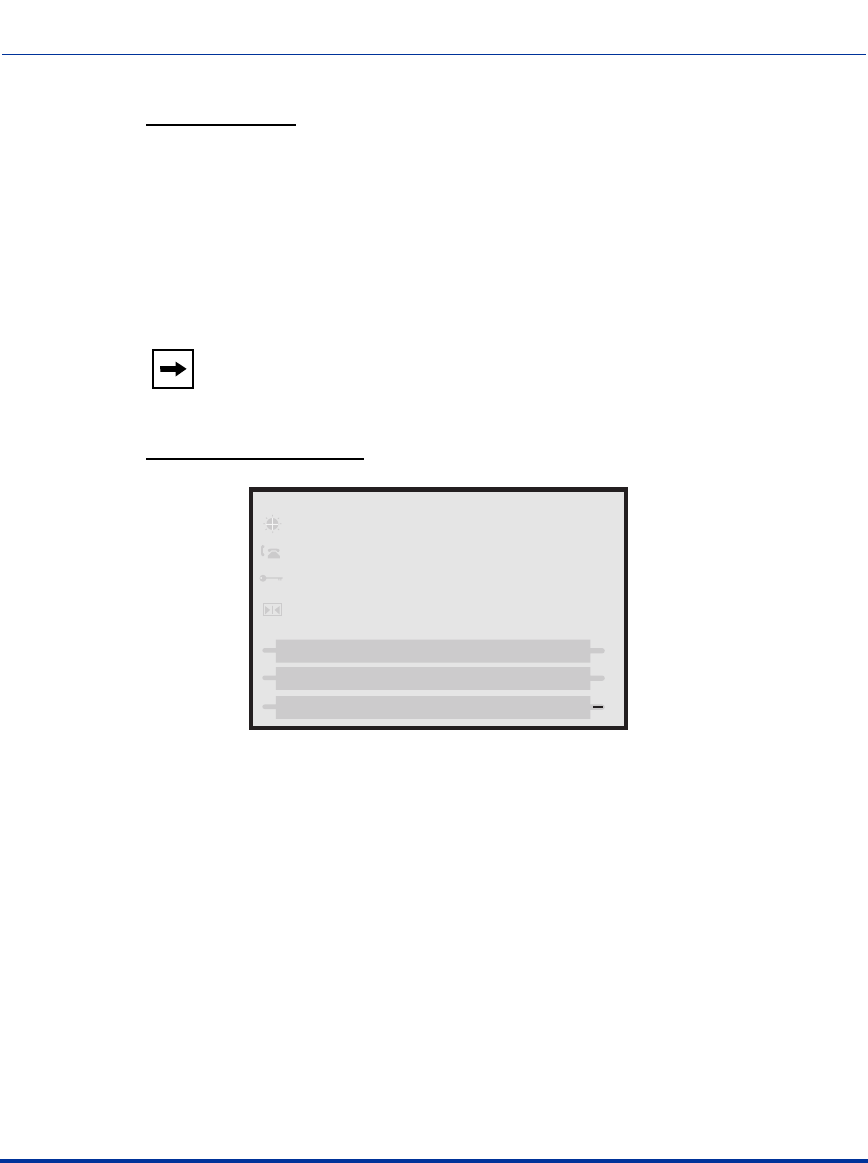
Creating an XML Application
41-001160-03, Rev 00, Release 2.4 F-15
XML Example 1:
<AastraIPPhoneTextScreen destroyOnExit = "yes">
<Title>Screen Object</Title>
<Text>The screen object can be implemented similar to the
firmware info screen. Note that white space is preserved in XML so
the display should word-wrap appropriately. Only three lines can
display at a time.</Text>
</AastraIPPhoneTextScreen>
XML Screen Example 1:
Note: This example displays text that you can scroll through on the LCD
screen. As you scroll the screen, the previous text is destroyed.
Screen Object
Done
The screen object can
be implemented
similar to the
Draft 1
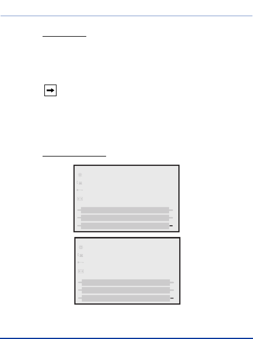
Creating an XML Application
F-16 41-001160-03, Rev 00, Release 2.4
IP Phone Administrator Guide
XML Example 2:
<AastraIPPhoneTextScreen doneAction=”http://10.50.10.117/
test.xml”>
<Title>Screen Object</Title>
<Text>For more information about this test, press Done.</Text>
</AastraIPPhoneTextScreen>
XML Screen Example 2:
Note: This example displays text that you can scroll through on the LCD
screen. As you scroll the screen, and then press DONE (9480i, 9480i CT,
6755i, 6757i, 6757i CT) or the RIGHT ARROW key (9143i and 6753i),
the screen redirects you to the location specified in the script. After
pressing DONE or the RIGHT ARROW key, the phone checks if a
“doneAction” exists in the XML script. If it does, the screen gets
redirected to the location specified. If it does not exist, then the scrolled
screens use the “destroyOnExit” attribute and destroy the screens.
Screen Object
Done
For more information about
this test, press DONE.
Done
TEST
Done
This screen displays the HTTP
screen that you have been
redirected to.
Draft 1

Creating an XML Application
41-001160-03, Rev 00, Release 2.4 F-17
XML Answer and Ignore Softkeys
When the IP phone receives an XML application (either via a post or an incoming
action URI) while a call is coming into the phone, the user can either answer or
ignore the call with new softkeys that display (9480i, 9480i CT, 6755i, 6757i, and
6757i CT), or press the left and right arrow keys (9143i and 6753i), without
canceling the XML application.
For a 9480i, 9480i CT, 6755i, 6757i, and 6757i CT, an Administrator can use the
“Answer” and “Ignore” attributes in an XML script to implement this feature.
For a 9143i and 6753i, an Administrator can use the “allowAnswer” attribute
with the AastraIPPhoneTextScreen XML object. Valid values for the
“allowAnswer” attribute are “yes” or “no” (default).
For 9480i, 9480i CT, 6755i, 6757i, and 6757i CT:
•The Answer and Ignore softkeys display on the LCD when the phone has an
incoming call at the same time it receives an XML application.
• XML applications are destroyed if the phone receives a call after the XML
has been rendered.
When the Answer softkey displays, you can press it to answer the incoming call
without disturbing the current XML application. When you answer the call, the
softkey disappears from the LCD. Pressing the Ignore softkey ignores the
incoming call without disturbing the current XML application.
Implementation (9480i, 9480i CT, 6755i, 6757i, 6757i CT)
Softkeys:
•1=Answer
• 2=Ignore
Draft 1

Creating an XML Application
F-18 41-001160-03, Rev 00, Release 2.4
IP Phone Administrator Guide
XML Example:
<SoftKey index="1">
<Label>Answer</Label>
<URI>SoftKey:Answer</URI>
</SoftKey>
<SoftKey index="2">
<Label>Answer</Label>
<URI>SoftKey:Ignore</URI>
</SoftKey>
XML Screen Example:
For 9143i, 6753i:
•An <Ignore Answer> line displays on the LCD when the phone receives an
incoming call at the same time it receives an XML application.
• XML applications are destroyed if the phone receives a call after the XML
has been rendered.
When the <Ignore Answer> line displays, you can press the Right Arrow key
(Answer) to answer the incoming call without disturbing the current XML
application. When you answer the call, the <Ignore Answer> line disappears from
the LCD. Pressing the Left Arrow key ignores the incoming call without
disturbing the current XML application.
, *OHN3MITH
!N8-,APPLICATIONCAN
DISPLAYHEREWHILEACALL
ISCOMINGIN
!NSWER
)GNORE
Draft 1
Creating an XML Application
41-001160-03, Rev 00, Release 2.4 F-19
Implementation (9143i, 6753i)
XML Example:
<AastraIPPhoneTextScreen allowAnswer = "yes">
<Title>Screen Object</Title>
<Text>The screen object can be implemented similar to the
firmware info screen. Note that white space is preserved in XML so
the display should word-wrap appropriately. Only three lines can
display at a time.</Text>
</AastraIPPhoneTextScreen>
XML Screen Example:
Text Screen Format Object (for Text Screens)
The AastraIPPhoneFormattedTextScreen object allows you to specify a format
for the text that displays in the LCD window on the phone. Using this object, you
can specify the following for the text that displays:
• alignment (using the “Align” attribute and specifying right, left, or center )*
• text size (using the “Line Size” attribute and specifying normal or double
height)*
• display type (using the “Line” or “Scroll” attributes to specify static or
scrolling)*
*See the AastraIPPhoneFormattedTextScreen structure example on page F-20.
The phone’s LCD screen allows up to a total of 5 lines for displaying text. The
formatted text displays in three distinct blocks in the order it is written in the XML
object:
• The first block displays text at the top of the LCD window. By default, this
text block is static. This block can contain as many lines as the XML object
specifies and can range from zero (0) up to the LCD screen size.
!N8-,APPLICATIONCANDISPLAY
HEREWHILEACALLISCOMINGIN
,JQRUH $QVZHU
Draft 1

Creating an XML Application
F-20 41-001160-03, Rev 00, Release 2.4
IP Phone Administrator Guide
• The second block displays below the first block. By default, the second text
block displays as scrolling text. This block takes up as many lines as the XML
developer specifies, up to the LCD screen size.
• The third block displays below the second block. By default, the third block
displays static text, and takes up whatever lines remain blank on the LCD
screen.
Using the AastraIPPhoneFormattedTextScreen object, the display truncates a line
after the last word in that line and continues to wrap the text to the next line.The
phone ignores any lines that display after the 5th line on the LCD screen.
AastraIPPhoneFormattedTextScreen Structure
The AastraIPPhoneFormattedTextScreen object describes the structure of the
XML document that you can use to format the text that displays on the phone’s
LCD screen. The default structure of the AastraIPPhoneFormattedTextScreen
object is:
<AastraIPPhoneFormattedTextScreen>
<Line Size="<normal/double>" Align="<right/left/center>">A line
of static text</Line>
<Scroll Height=n>
<Line Size="<normal/double>" Align="<right/left/center>">
Scrolling text</Line>
<Line>Another line of Scrolling Text</Line>
<Line>Yet another scrolling line</Line>
</Scroll>
<Line>Some static footer text</Line>
</AastraIPPhoneFormattedTextScreen>
Note: Any of the three blocks can be set as static text or scrolling text but
the text displays on a total of 5 lines only. Any lines that display after line
5 are lost.
Note: The text in bold in the above structure indicate the options you can
use for text size (normal, double), alignment (right, left, center), and
scrolling height (from 1 to 5 lines). Setting a scrolling height less than “1”
automatically sets the scroller height to “1”.
Draft 1

Creating an XML Application
41-001160-03, Rev 00, Release 2.4 F-21
XML Example:
The following is an example of using the AastraIPPhoneFormattedTextScreen
object with a static line at the top and bottom blocks and 2 scrolling lines in the
middle block.
<AastraIPPhoneFormattedTextScreen>
<Line Size="double" Align="left">A line of static text</Line>
<Scroll Height=2>
<Line Size="normal" Align="right"> Scrolling text</Line>
<Line>Another line of Scrolling Text</Line>
<Line>Yet another scrolling line</Line>
</Scroll>
<Line>Some static footer text</Line>
</AastraIPPhoneFormattedTextScreen>
XML Screen Examples:
IP Phones 9480i, 9480i CT, 6755i, 6757i, and 6757i CT
IP Phone 9143i, 6751i, 6753i
Done
A line of static text
This block can scroll
using the down arrow
on the navigation keys.
A line of static text
A line of static text
This block can scroll
Draft 1
Creating an XML Application
F-22 41-001160-03, Rev 00, Release 2.4
IP Phone Administrator Guide
Dialpad Passthrough for Objects
On the IP Phones, an XML Developer can control digit passthrough while the
phone is in the connected state. (This feature is only applicable to phones in the
connected state). This can be done by setting the new “allowDTMF” attribute
with the XML objects AastraIPPhoneTextScreen,
AastraIPPhoneFormattedTextScreen, and AastraIPPhoneImageScreen.
Setting this attribute to “yes” allows dialpad events to pass through the XML
applications.
Examples
• The following is an example of setting the allowDTMF attribute to allow
dialpad events to pass through the XML applications.
<AastraIPPhoneTextScreen allowDTMF="yes">
<Title>Test</Title>
<Text>Digits should pass through this object</Text>
</AastraIPPhoneTextScreen>
• The following is an example of setting the allowDTMF attribute to prevent
dialpad events from passing through the XML applications (this is the default
setting).
<AastraIPPhoneTextScreen allowDTMF="no">
<Title>Test</Title>
<Text>Digits do not pass through this object</Text>
</AastraIPPhoneTextScreen>
Note: You can view all 5 lines at once on the 9480i, 9480i CT, 6755i,
6757i and 6757i CT IP phones. You can view only 2 lines at a time (up to
5 lines) on the 9143i, 6751i, 6753i IP phone.
Note: The default behavior for this feature is to suppress dialpad events
when an XML object is in focus (same as in previous releases). Other
XML objects ignore this attribute.
Draft 1

Creating an XML Application
41-001160-03, Rev 00, Release 2.4 F-23
UserInput Object (User Input Screens)
The AastraIPPhoneInputScreen object allows application developers to create
screens for which the user can input text where applicable. (Line 1 is a title, Line 4
is an input prompt, and Line 5 is an input field). The IP phones support three
parameter types: IP Addresses, Numbers (integers), and Strings. Each parameter
has a URL tag that is used to send information back to the HTTP server. The label
in the parameter tag is appended to the address in the URL tag and sent via HTTP
GET.
For User input screens, you can also create the following:
• Time and Date Format User input screens. For more information, see “Time
and Date Formats (User Input Screens)” on page F-31.
• Multiple input fields per AastraIPPhoneInputScreen object. For more
information, see “Multiple Input Fields (User Input Screens)” on page F-34.
Implementation (IP Addresss)
The following is how you would implement the AastraIPPhoneInputScreen
object using an IP Address.
Softkeys:
• 1=Backspace
•2=Dot
• 3=ChangeCase
• 4=Numeric/Alpha
• 5=Cancel
•6=Done
Note: For all available parameters you can use for the
AastraIPPhoneInputScreen object, and for an explanation of each
parameter, see Aastra Telecom’s "XML Developer’s Guide".
Draft 1

Creating an XML Application
F-24 41-001160-03, Rev 00, Release 2.4
IP Phone Administrator Guide
XML Description:
<AastraIPPhoneInputScreen type = "IP/string/number" password =
"yes/no" destroyOnExit = "yes/no">
<!-password attribute is optional and set to "no" by defaultà
<!-destroyOnExit is optional and "no" by default à
<Title>Title string, usually same as menu title</Title>
<Prompt>Enter IP address or host name</Prompt>
<URL>Target receiving the input</URL>
<Parameter>parameter added to URL</Parameter>
<Default />
<SoftKey index = "1">
<Label> Backspace </Label>
<URI>SoftKey:Exit</URI>
</Softkey>
<SoftKey index = "2">
<Label> Dot </Label>
<URI>SoftKey:Exit</URI>
</Softkey>
<SoftKey index = "3">
<Label> ChangeCase </Label>
<URI>SoftKey:Exit</URI>
</Softkey>
<SoftKey index = "4">
<Label> Numeric/Alpha </Label>
<URI>SoftKey:Exit</URI>
</Softkey>
<SoftKey index = "5">
<Label> Cancel </Label>
<URI>SoftKey:Exit</URI>
</Softkey>
<SoftKey index = "6">
<Label> Done </Label>
<URI>SoftKey:Exit</URI>
</Softkey>
</AastraIPPhoneInputScreen>
Draft 1
Creating an XML Application
41-001160-03, Rev 00, Release 2.4 F-25
XML Example:
<AastraIPPhoneInputScreen type = "IP">
<Title>Proxy Server</Title>
<Prompt>Server IP:</Prompt>
<URL>http://10.50.10.53/script.pl</URL>
<Parameter>proxy</Parameter>
<Default></Default>
<AastraIPPhoneInputScreen>
XML Screen Example:
Proxy Server
Backspace
Done
Server IP:
Dot Cancel
Draft 1
Creating an XML Application
F-26 41-001160-03, Rev 00, Release 2.4
IP Phone Administrator Guide
Implementation (Number)
The following is how you would implement the UserInput object using Numbers.
Softkeys:
• 1=Backspace,
• 5=Cancel,
•6=Done
XML Example:
<AastraIPPhoneInputScreen type = "number">
<Title>Proxy Port</Title>
<Prompt>Port:</Prompt>
<URL>http://10.50.10.53/script.pl</URL>
<Parameter>port</Parameter>
<Default>5060</Default>
<AastraIPPhoneInputScreen>
XML Screen Example:
Proxy Port
Backspace
Done
Port: 5060
Cancel
Draft 1
Creating an XML Application
41-001160-03, Rev 00, Release 2.4 F-27
Implementation (String)
The following is how you would implement the UserInput object using Strings in
XML.
Softkeys:
• 1=Backspace,
•2=Dot,
• 3=Tri-Mode key,
• 4=Nextspace,
• 5=Cancel,
•6=Done
XML Example:
<AastraIPPhoneInputScreen type = "string" password = "yes">
<Title>SIP Settings</Title>
<Prompt>Enter something</Prompt>
<URL>http://10.50.10.53/script.pl</URL>
<Parameter>passwd</Parameter>
<Default></Default>
<AastraIPPhoneInputScreen>
XML Screen Example::
Note: In the above example, if the user entered 12345, then the URL sent
back to the server is http://10.50.10.53/script.pl?passwd=12345.
SIP Settings
Backspace
Done
Enter Password:
******
Cancel
Dot
ABC
Nextspace
Draft 1
Creating an XML Application
F-28 41-001160-03, Rev 00, Release 2.4
IP Phone Administrator Guide
XML Softkey for Special Characters
(User Input Screens for 9480i, 9480i CT, 6755i, 6757i, and 6757i CT only)
The IP Phone can dynamically receive a Symbol List when it receives the
AastraIPPhoneInputScreen XML object. You can have a single symbol
specified for the softkey, or you can have a list of symbols. When there is only one
symbol in the list, the symbol displays with no delay. When there is a list of
symbols, you can keep pressing the symbol softkey to cycle through the list of
symbols to select the one you want to use.
To display a list of customized symbols to the phone’s softkey, the server must
include the list of characters in the URI field of the XML softkey script. The URI
must be in the format:
SymbolList=”<Symbol List content>”
The content of the Symbol List must be encapsulated by quotes. You can specify
multiple symbols in one URI. For example, the SymbolList="@#” specifies the
@ and # symbols.
There are some special characters that needed to be encoded due to XML
limitations. The following table specifies these characters.
The following is an example XML URI using the characters in the table above:
SymbolList="@#&><"
The Symbol List content for this URI is @, #, &, >, <.
Note: You can have multiple Symbol List softkeys with different lists of
symbols. The maximum length of the data in a Symbol List is 230
characters.
Symbol XML Encoding
single quote (‘) '
double quote (“) "
greater-than sign (>) >
less-than sign (<) <
ampersand (&) &
Draft 1
Creating an XML Application
41-001160-03, Rev 00, Release 2.4 F-29
Implementation
Softkeys:
• 1 = <Single Symbol or Symbol List>
XML Softkey Example:
<SoftKey index="1">
<Label>Symbols</Label>
<URI>SoftKey:SymbolList="@#=&"</URI>
</SoftKey>
XML Object and Softkey Example:
<AastraIPPhoneInputScreen type = "IP">
<Title>Email</Title>
<SoftKey index="1">
<Label>Symbols</Label>
<URI>SoftKey:SymbolList="@"</URI>
</SoftKey>
<SoftKey index = "2">
<Label> Backspace </Label>
<URI>SoftKey:Exit</URI>
</Softkey>
<SoftKey index = "3">
<Label> Dot </Label>
<URI>SoftKey:Exit</URI>
</Softkey>
<Prompt>Email Address:</Prompt>
<URL>http://myserver.com/myscript.com</URL>
<Parameter>email</Parameter>
<Default></Default>
<AastraIPPhoneInputScreen>
XML Screen Example:
%MAIL
3YMBOLS
"ACKSPACE
$OThv
%MAIL!DDRESS
Draft 1

Creating an XML Application
F-30 41-001160-03, Rev 00, Release 2.4
IP Phone Administrator Guide
XML Softkeys for Drop, Conf, and Xfer
The Drop, Conf and Xfer softkeys can be customized to use with XML objects
and display on XML screens as required. These custom softkeys are active ONLY
in the connected state. They are available for the following screen objects:
• TextScreen
• FormattedTextScreen
•TextMenu
• InputScreen
• ImageMenu
• ImageScreen
For XML screens on the 6755i, 6757i, 6757i CT, 9480i, and 9480i CT phones
with large LCDs, the Drop, Conf and Xfer custom softkeys display on one screen.
For XML screens on the 6751i, 6753i, and 9143i phones with small LCDs, adding
the "allowDrop", "allowConf" or "allowXfer" attribute to the root tag of the UI
XML object allows the corresponding Drop, Conf, or Xfer key to be shown on the
command line.
XML Example:
<AastraIPPhoneTextScreen
Beep="no" allowDrop="yes" allowConf="yes" allowXfer="yes">
<Title></Title>
<Text>Username and Phone number</Text>
</AastraIPPhoneTextScreen>
For the smaller LCDs, if all three attributes are included in the XML object, only
the Conf and Xfer keys display as shown above.
John Doe
5157
Conf Xfer
Draft 1

Creating an XML Application
41-001160-03, Rev 00, Release 2.4 F-31
For all phones, once the user presses the custom softkey (Drop, Conf, Xfer), the
softkey disappears after the action is performed. For example, after pressing the
Xfer key on an active call from an XML screen, the Xfer key disappears and the
dialing screen appears.
Time and Date Formats (User Input Screens)
The AastraIPPhoneInputScreen object allows you to specify US ( (HH:MM:SS
am/pm and MM/DD/YYYY) or International (HH:MM:SS and DD/MM/YYYY)
time/date formats for an XML user input screen on the IP phone.
Using this AastraIPPhoneInputScreen object, you can specify the following
attributes for date/time format to create the user input screen:
•“timeUS”
•“timeInt”
•“US Date”
• “Int Date”
You can use these XML attributes in an application that requires the user to
specify a time or a date, for example, when scheduling a meeting. The user could
press a softkey that gets the XML script asking you to enter a time/date. This time/
date is then forwarded to a script that schedules the meeting or reports a conflict.
XML Examples:
The following example illustrates the AastraIPPhoneInputScreen object using the
time/date attributes.
United StatesTime
<AastraIPPhoneInputScreen type="timeUS">
<Title>US Time</Title>
<Prompt>Enter Current Time:</Prompt>
<Parameter>Time</Parameter>
</AastraIPPhoneInputScreen>
Note: You use this time/date format in an XML script that displays in an
XML window. This time/date format does NOT affect the time/date
format configured under the Options Menu on the phone.
Draft 1
Creating an XML Application
F-32 41-001160-03, Rev 00, Release 2.4
IP Phone Administrator Guide
IP Phones 9480i, 9480i CT, 6755i, 6757i/6757i CT IP Phone 9143i, 6753i
International Time
<AastraIPPhoneInputScreen type="timeInt">
<Title>Int Time</Title>
<Prompt>Enter Current Time:</Prompt>
<Parameter>Time</Parameter>
<Default>14:23:22</Default>
</AastraIPPhoneInputScreen>
IP Phones 9480i, 9480i CT, 6755i, 6757i/6757i CT IP Phone 9143i, 6753i
Note: If you don’t specify a time, the XML script uses the following
default values:
- 12:00:00am (US)
- 00:00:00 (International)
US Time
Done
Enter Current Time:
12:00:00am
Cancel
Enter Current Time:
12:00:00am
=Enter
=Cancel
Int Time
Done
Enter Current Time:
14:23:22
Cancel
Enter Current Time:
12:23:22
=Enter
=Cancel
Draft 1
Creating an XML Application
41-001160-03, Rev 00, Release 2.4 F-33
United States Date
<AastraIPPhoneInputScreen type="dateUS">
<Title>US Date</Title>
<Prompt>Enter Birthday:</Prompt>
<Parameter>Date</Parameter>
<Default>12/22/1980</Default>
</AastraIPPhoneInputScreen>
IP Phones 9480i, 9480i CT, 6755i, 6757i/6757i CT IP Phone 9143i, 6753i
International Date
<AastraIPPhoneInputScreen type="dateInt">
<Title>Int Date</Title>
<Prompt>Enter Birthday:</Prompt>
<Parameter>Date</Parameter>
</AastraIPPhoneInputScreen>
IP Phones 9480i, 9480i CT, 6755i, 6757i/6757i CT IP Phone 9143i, 6753i
US Date
Done
Enter Birthday:
12/22/1980
Cancel
Enter Birthday:
12/22/1980
=Enter
=Cancel
Int Date
Done
Enter Birthday:
26/5/2006
Cancel
Enter Birthday:
26/5/2006
=Enter
=Cancel
Draft 1
Creating an XML Application
F-34 41-001160-03, Rev 00, Release 2.4
IP Phone Administrator Guide
Multiple Input Fields (User Input Screens)
You can have multiple input fields per AastraIPPhoneInputScreen object.The
following specifications apply to this feature:
• Multiple input fields are applicable to 9480i. 9480i CT, 6755i, 6757i, and
6757i CT IP phones only.
• Each AastraIPPhoneInputScreen object can support up to 6 input fields.
• Each input field supports its own set of custom softkeys (these take
precedance over any softkeys configured outside of the <InputField> tags.
• The phone treats softkey information specified outside of the <InputField>
tags as a default value.
• Each AastraIPPhoneInputScreen object supports only 1 URL.
The following tags support this feature.
Note: If you don’t specify a date, the XML script uses the current date in
the specified format.
Tags for Multiple Input Fields
<InputField>.......</InputField>
Note: This tag supports the type,
password, and editable
attributes. If specified, they
override the default values
provided in the root tag.
New tags within the <InputField>
tags:
<Prompt>
<Parameter>
<Default>
<Softkey>
Note: These tags override the values
specified outside of the <InputField>
tags.
<Selection>.......</Selection> Any data specified between the
<Selection> tags is appended to the
URI in the form Selection = <DATA>.
Draft 1

Creating an XML Application
41-001160-03, Rev 00, Release 2.4 F-35
You use the following attributes to create multiple input fields using the
AastraIPPhoneInputScreen object.
Example
The following is an example AastraIPPhoneInputScreen script using the multiple
input field feature:
<AastraIPPhoneInputScreen type="string">
<Title>Test</Title>
<URL>http://10.50.10.117/test.pl</URL>
<Default/>
<InputField>
<Prompt>Name:</Prompt>
<Parameter>name</Paramter>
<Default>Robert</Default>
<SoftKey index="3">
<Label>NameDone</Label>
<URI>Softkey:Submit</URI>
</SoftKey>
</InputField>
<InputField type="timeUS">
New AastraIPPhoneInputScreen Attributes
defaultIndex Allows you to set an integer value from 1 - 6 that specifies which
input field the edit cursor starts in. Default is 1.
displayMode Allows you to set a specific display mode for the screen: “normal”
or “condensed”.
Default is “normal” mode.
Normal Mode - Prompts and inputs each appear on separate lines
on the display. The user can scroll through the lines.
Notes:
1. An <InputField> tag with a type set to “empty” creates two blank
lines in “normal” mode.
2. All inputs fields are left justfied in “normal” mode.
Condensed Mode - Prompts and inputs appear on the same line
(up to 5 inputs on a single screen).
Notes:
1. Title tag wrapping limits the number of fields per screen to 1 or 3
in condensed mode.
2. An <InputField> tag with a type set to “empty” creates a blank
line in “condensed” mode.
Draft 1

Creating an XML Application
F-36 41-001160-03, Rev 00, Release 2.4
IP Phone Administrator Guide
<Prompt>Time:</Prompt>
<Parameter>time</Paramter>
<Default>10:50:24AM</Default>
</InputField>
<InputField type="dateUS>
<Prompt>Date:</Prompt>
<Parameter>date</Paramter>
<Default>01/24/07</Default>
<SoftKey index="5">
<Label>DateDone</Label>
<URI>Softkey:Submit</URI>
</SoftKey>
</InputField>
</AastraIPPhoneInputScreen>
Posting the above AastraIPPhoneInputScreen XML script displays the following
screens on the IP phone.
Screen 1 Note: Notice that the cursor is active within the first element field and
that the phone is displaying the InputField #1 softkey.
Test
Name:
Robert |
Time:
10:50:24 AM
____________________
- NameDone
Cursor
Screen 1
Draft 1

Creating an XML Application
41-001160-03, Rev 00, Release 2.4 F-37
Scolling down changes to the next input field.
Screen 2 Note: Notice that the softkeys change to reflect the new input type,
timeUS.
Scrolling down again goes to the next page of inputs.
Screen 3 Note: Notice that the softkeys change again to reflect the current input
item on the screen (Date).
Test
Name:
Robert
Time:
10:50:24 AM
____________________
Cancel -
Done -
Screen 2
Test
Date
11/24/07
____________________
DateDone -
Screen 3
Draft 1

Creating an XML Application
F-38 41-001160-03, Rev 00, Release 2.4
IP Phone Administrator Guide
Condensed Mode Screen
If you use the attribute “displayMode = “condensed” in the root tag (Screen 4),
the display changes to have prompt and inputs on the same line. The behavior of
the screens using “condensed” mode is the same as Screens 1 through 3 but
without the scrolling.
Test
Name: Robert |
Time: 10:50:24 AM
Date: 11/24/07
____________________
- NameDone
Screen 4
Draft 1

Creating an XML Application
41-001160-03, Rev 00, Release 2.4 F-39
Directory Object (Directory List Screen)
The Directory object allows you to browse an online directory in real time. It
displays an automatically numbered list of contacts. By selecting a contact with
the cursor, the contact can be dialed directly by pressing the "Dial" softkey or
picking up the receiver. The Directory object has the optional softkeys of
"Previous" and "Next" which can be linked to other XML objects.
Implementation
The following is how you would implement the Directory object in XML.
Softkeys:
• 1=Dial,
•6= Done,
• 2=Previous (optional),
• 5=Next (optional)
XML Description:
<AastraIPPhoneDirectory destroyOnExit="no" next="uri"
previous="uri">
<!-Attributes are optionalà
<Title>Directory Title</Title>
<MenuItem>
<Prompt>Contact Name</Prompt>
<URI>number</URI>
</MenuItem>
<!-Additional Menu Items may be added -->
</AastraIPPhoneDirectory>
Note:
1. For all available parameters you can use for the Directory object, and
for an explanation of each parameter, see Aastra Telecom’s
"XML Developer’s Guide".
2. If the URI entry contains a "?" the phone appends an "&" instead.
Draft 1
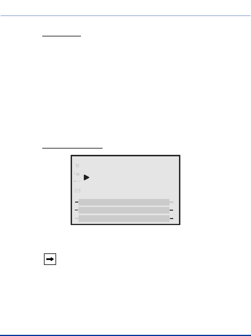
Creating an XML Application
F-40 41-001160-03, Rev 00, Release 2.4
IP Phone Administrator Guide
XML Example:
<AastraIPPhoneDirectory> next="more.xml" previous="back.xml">
<Title>My Directory</Title>
<MenuItem>
<Prompt>6757i - John Doe 1</Prompt>
<URI> 10.50.10.49</URI>
</MenuItem>
<MenuItem>
<Prompt>6753i - John Doe 2</Prompt>
<URI>4326</URI>
</MenuItem>
<MenuItem>
<Prompt>6757i CT - John Doe 3</Prompt>
<URI>9982691234</URI>
</MenuItem>
</AastraIPPhoneDirectory>
XML Screen Example::
Note: The maximum number of items to be included in a Directory
object is 15 per page. In this example, there are six pages.
My Directory (1/6)
Dial
Cancel
Next
Previous
2. 9133i John Doe 2
1. 480i John Doe 1
3. 480iCT John Doe 3
Draft 1

Creating an XML Application
41-001160-03, Rev 00, Release 2.4 F-41
Status Message Object (Idle Screen)
The IP phones support an XML AastraIPPhoneStatus object for displaying
status messages on a single designated line on the phone’s idle screen. The
messages display when the server pushes XML information to the phone.
The 6757i/6757i CT phones display messages on the second line in the phone
window. (where “No Service” would display if there was no service. If there is no
service on the phone, the “No Service” message overrides the XML object
message). The 6753i phone displays messages on the first line (overriding the
DisplayName). The phone truncates long messages that are wider then the phone
screen.
If the phone receives multiple messages, the first message received displays first
and the remaining messages scroll consecutively one at a time. Messages remain
displayed until they are removed (by the server) or the phone reboots. The
AastraIPPhoneStatus object feature is always enabled.
AastraIPPhoneStatus Structure
The AastraIPPhoneStatus object describes the structure of the XML document
that you can use to send status messages to the phone. The basic structure of the
AastraIPPhoneStatus object is:
<AastraIPPhoneStatus>
<Session>My session ID</Session>
<Message index="Msg index">Message</Message>
<! -- Additional status messages may be added under new Message tags-->
<AastraIPPhoneStatus/>
The ”My Session ID” attribute must be unique to the application sending the
XML object to the phone. The application generates the session ID, which could
be a combination of letters and numbers. There is a maximum of one <Session>
tag per PhoneStatus object, so the <Session> tag is optional.
Note: You can set the amount of time, in seconds, that a message displays
to the phone before scrolling to the next message. For more information
about this feature, see “Scroll Delay Option (configurable via config files
and Aastra Web UI only)” on page F-80.
Draft 1

Creating an XML Application
F-42 41-001160-03, Rev 00, Release 2.4
IP Phone Administrator Guide
XML Examples
Example 1: The following is an example of using the AastraIPPhoneStatus
object:
<AastraIPPhoneStatus>
<Session>abc12345</Session>
<Message index="3">Server side call forwarding disabled</Message>
<AastraIPPhoneStatus/>
In this example, the AastraIPPhoneStatus object sends the default behavior with
the status message (i.e., the status message is added to the scroll list).
Example 2: You can also use the AastraIPPhoneStatus object to remove status
messages from the display, by setting an empty tag for the <Message index> tag.
The following example removes the status message that was posted to the phone
in Example 1.
<AastraIPPhoneStatus>
<Session>abc12345</Session>
<Message index="3"/>
<AastraIPPhoneStatus/>
Draft 1

Creating an XML Application
41-001160-03, Rev 00, Release 2.4 F-43
Execute Commands Object (for executing XML commands)
An AastraIPPhoneExecute object on the IP phones allows the phone to execute
commands using XML. The phones support the following execute object
commands:
•Reset - This command waits until the phone is idle and then executes a reset.
You can use this command in an XML script to enable the server to force
phone firmware changes and/or for troubleshooting purposes.
•NoOp - This command has no affect on the IP phone. It is made up of a blank
URI. You can use this feature when you need to press a key on the phone to
access a feature, and it is not necessary to display anything.
•FastReboot - This command allows an administrator to perform a fast reboot
of the IP phone when required.
•XML Softkey/Programmable Key LED Behavior - The URI=”Led:
<softkey or programmable key type>=<execute command>”/ controls the
behavior of XML softkey or programmable key LEDs. The softkey or
programmable key must be configured for XML before you enable this
feature.
The following paragraphs describe the AastraIPPhoneExecute object and the
commands you can use with this object.
AastraIPPhoneExecute Object Structure
The AastraIPPhoneExecute object describes the structure of the XML document
that you can use to send a command to the phone. It delivers multiple execution
requests to the phone. The basic structure of the AastraIPPhoneExecute object is:
<AastraIPPhoneExecute>
<ExecuteItem URI ="the URL or URI to be executed"/>
<! -- Additional execution items may be added under new ExecuteItem tag-->
</AastraIPPhoneExecute>
Note: For FastReboot commands, you must set the XML push server list
in the Aastra Web UI from where the XML HTTP post is being sent.
Draft 1

Creating an XML Application
F-44 41-001160-03, Rev 00, Release 2.4
IP Phone Administrator Guide
Using the Reset Command
The <ExecuteItem URI =""/> tag can be entered with the command the phone
should execute. Upon receiving an AastraIPPhoneExecute object, the phone
begins executing the URL or URI specified.
The following example shows an AastraIPPhoneExecute object using the Reset
command:
<AastraIPPhoneExecute>
<ExecuteItem URI="Command: Reset"/>
</AastraIPPhoneExecute>
The following example shows the AastraIPPhoneExecute object using a URL:
<AastraIPPhoneExecute>
<ExecuteItem URI="http://aastraserver/message.xml"/>
</AastraIPPhoneExecute>
When the phone receives this object, it displays the specified XML URI page.
Using the NoOp Command
You can use the AastraIPPhoneExecute object as an object to create a blank
display (it has no affect on the IP phone). It is made up of a blank URI. You can
use this feature when you need to press a key on the phone to access a feature, and
it is not necessary to display anything. You can also use the
AastraIPPhoneExecute object and this command with other objects in an XML
script.
The following example shows an AastraIPPhoneExecute object using a blank
URI:
<AastraIPPhoneExecute>
<ExecuteItem URI=””/>
<AastraIPPhoneExecute>
Note: If you specify a command as a URI attribute (instead of a URL),
the keyword "Command" must be prepended in the value of the URI
attribute so that the phone recognizes it as a URI attribute value. If you
enter a URI and leave out the “Command” keyword, the phone interprets
the value in the URI attribute as a URL containing network resources.
Draft 1
Creating an XML Application
41-001160-03, Rev 00, Release 2.4 F-45
Using the FastReboot Command
Using an XML post, the FastReboot feature forces a phone to reboot in the idle
state. It does not check for new firmware and only downloads language packs if
there is a change in the supported filenames of the language packs. The phone
DOES do a DHCP lookup on every “fast reboot”. It also only downloads the
Directory files if the names have changed.
The following example shows an AastraIPPhoneExecute object using the
FastReboot command.
<AastraIPPhoneExecute>
<ExecuteItem URI=“Command:FastReboot”/>
</AastraIPPhoneExecute>
Using the LED Commands (for Softkey or Programmable Key LED
Behavior)
You can control the behavior of XML softkey or programmable key LEDs using
the command URI=”Led: <softkey or programmable key type>=<execute
command>”/ with the AastraIPPhoneExecute object.
This LED feature is applicable to XML softkeys (top or bottom), programmable
keys, and expansion module softkeys. The softkey or programmable key must be
configured for XML before you enable this feature.
The following table describes the behaviors you can assign to the XML key
LEDs, and the attribute you enter in the AastraIPPhoneExecute script.
Note: For FastReboot commands, you must set the XML push server list
in the Aastra Web UI from where the XML HTTP post is being sent.
LED Behavior XML Attribute
on URI = “Led: <softkey type>= on”/
off URI = “Led: <softkey type>=off”/
fastFlash URI = “Led: <softkey type>=fastflash”/
slowFlash URI = “Led: <softkey type>=slowflash”/
Draft 1

Creating an XML Application
F-46 41-001160-03, Rev 00, Release 2.4
IP Phone Administrator Guide
The command for LED control is sent using the XML HTTP post from one of the
XML push server lists. The following example shows an XML LED command in
an AastraIPPhoneExecute script.
<AastraIPPhoneExecute>
<ExecuteItem URI=”Led: topsoftkey20=on”/>
<ExecuteItem URI=”Led: softkey1=off”/>
<ExecuteItem URI=”Led: prgkey2=fastflash”/>
<ExecuteItem URI=”Led: expmod2 key20=slowflash”/>
</AastraIPPhoneExecute>
Using the Lock and Unlock Commands
There are two XML Execute Commands that allow a remote phone to be locked
or unlocked.
•Lock - This command locks a remote phone.
•Unlock - This command unlocks a remote phone, allowing an Administrator
to update its configuration if required.
The following examples use the “Lock” and “Unlock” attributes with the Execute
Command.
Example 1:
<AastraIPPhoneExecute>
<ExecuteItem URI="Command: Unlock"/>
</AastraIPPhoneExecute>
The phone gets unlocked.
Example 2:
Server sends XML Execute to the phone using HTTP POST.
<AastraIPPhoneExecute>
<ExecuteItem URI="Command: Lock"/>
</AastraIPPhoneExecute>
The phone gets locked.
Notes:
1. Using the Aastra Web UI, you must set the XML push server list
from where the XML HTTP post is being sent.
2. The LED states specified in the AastraIPPhoneExecute script are
not saved after a reboot.
Draft 1

Creating an XML Application
41-001160-03, Rev 00, Release 2.4 F-47
Example 3:
Phone is getting booted.
Startup Action URI is called.
Server responses with:
<AastraIPPhoneExecute>
<ExecuteItem URI="Command: Unlock"/>
<ExecuteItem URI="http://server:port/pathtosoftkeyconfig"/>
</AastraIPPhoneExecute>
The phone gets unlocked and the second URL gets loaded.
Using RTP and Multicast RTP Commands
The IP Phones have RTP and Multicast RTP XML commands that an
Administrator can use with the “AastraIPPhoneExecute” object. These
commands allow the phone to send/recieve an RTP stream to/from given
multicast/unicast addresses (without involving SIP signaling). The RTP and
Multicast RTP XML commands are:
•RTPRx (Receive (Rx) a Unicast RTP stream or stop receiving a Unicast/
Multicast RTP streams)
•RTPTx (Transmit (Tx) a Unicast RTP stream or stop transmitting a Unicast/
Multicast RTP streams)
•RTPMRx (Receive (Rx) a Multicast RTP stream)
•RTPMTx (Transmit (Tx) a Multicast RTP stream)
The phones support the following RTP stream format:
• G.711 mu-law CODEC
• 20 ms packet size
Note: If one of the previous commands is sent to the phone which is
already in a call, the phone places the current call on hold and the RTP
streaming commands are performed using a new audio path.
Draft 1
Creating an XML Application
F-48 41-001160-03, Rev 00, Release 2.4
IP Phone Administrator Guide
RTPRx
The RTPRx URI instructs the phone to receive a Unicast RTP stream or stop
receiving Unicast or Multicast RTP streams. The RTPRx formats to use with the
AastraIPPhoneExecute object in the URI are:
• RTPRx:i:p:v
• RTPRx:Stop
Where
iSpecifies the IP Address from which the stream is coming.
pSpecifies the UDP port on which to receive the RTP stream.
Ensure that this is a number greater than 3100.
v
(optional) Indicates the optional volume setting that controls the volume of the stream
playout. The supplied value is an offset to the current volume setting. After the
initial volume level gets set and the stream starts, you can manually change
the volume level as required using this “v” option. If you do not specify the
optional volume parameter, the phone uses the current volume setting on the
phone as the default.
Stop Specifies to stop any active RTP stream from being received on channel one.
Example: This example receives a unicast RTP stream from 10.30.100.20 at UDP port
21000 with the voice settings at 3 levels more than the current offset.
<AastraIPPhoneExecute>
<ExecuteItem URI = ”RTPRx:10.30.100.20:21000:3”>
<AastraIPPhoneExecute>
Example:
This example receives a unicast RTP stream from 10.30.100.20 at UDP port 21000 with
the voice settings as used in the previous RTP stream.
<AastraIPPhoneExecute>
<ExecuteItem URI = ”RTPRx:10.30.100.20:21000”>
<AastraIPPhoneExecute>
Example:
This example stops an incoming active multicast/unicast RTP stream.
<AastraIPPhoneExecute>
<ExecuteItem URI=”RTPRx:Stop”>
<AastraIPPhoneExecute>
Draft 1
Creating an XML Application
41-001160-03, Rev 00, Release 2.4 F-49
RTPTx
The RTPTx URI instructs the phone to transmit a Unicast RTP stream or to stop
transmitting Unicast or Multicast RTP streams. The RTPTx formats to use with
the AastraIPPhoneExecute object in the URI are:
• RTPTx:i:p
• RTPTx:Stop
Note: Once the RTPRx command in the URI is sent to the phone, it stops
the phone from listening to any previous RTPRx or RTPMRx commands.
The phone starts listening based on the most recent RTPRx command
received. This behavior also applies to the RTPRx:Stop and
RTPMRx:Stop commands as well but does not enable any further
listening.
Where
iSpecifies the IP Address to which an RTP stream is transmit ed.
pSpecifies the UDP port on which to transmit the RTP stream.
Ensure that this is a number greater than 3100.
Stop Specifies to stop any active RTP stream from being transmitted on channel
one.
Example: This example sends a unicast RTP stream to 10.30.100.20 on UDP port
21000.
<AastraIPPhoneExecute>
<ExecuteItem URI = ”RTPTx:10.30.100.20:21000”>
<AastraIPPhoneExecute>
Example:
This example stops an outgoing active multicast/unicast RTP stream.
<AastraIPPhoneExecute>
<ExecuteItem URI=”RTPTx:Stop”>
<AastraIPPhoneExecute>
Draft 1
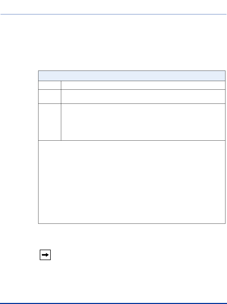
Creating an XML Application
F-50 41-001160-03, Rev 00, Release 2.4
IP Phone Administrator Guide
RTPMRx
The RTPMRx URI instructs the phone to receive a Multicast RTP stream. The
RTPMRx format to use with the AastraIPPhoneExecute object in the URI is:
•RTPMRx:i:p:v
Where
iSpecifies the multicast IP Address from which to receive an RTP stream.
pSpecifies the UDP port on which to receive the RTP stream.
Ensure that this is a number greater than 3100.
v
(optional) Indicates the optional volume setting that controls the volume of the stream
playout. The supplied value is an offset to the current volume setting. After the
initial volume level gets set and the stream starts, you can manually change
the volume level as required using this “v” option. If you do not specify the
optional volume parameter, the phone uses the current volume setting on the
phone as the default.
Example: This example receives a multicast RTP stream from 239.0.1.20 on UDP port
21000 with the voice settings at -3 levels less than the current offset.
<AastraIPPhoneExecute>
<ExecuteItem URI = ”RTPMRx:239.0.1.20:21000:-3”>
<AastraIPPhoneExecute>
Example:
This example receives a multicast RTP stream from 239.0.1.20 at UDP port 21000 with
the voice settings as used in the previous RTP stream.
<AastraIPPhoneExecute>
<ExecuteItem URI = ”RTPMRx:239.0.1.20:21000”>
<AastraIPPhoneExecute>
Note: Once the RTPMRx command in the URI is sent to the phone, it
stops the phone from listening to any previous RTPRx or RTPMRx
commands. The phone starts listening based on the most recent RTPMRx
command received. This behavior also applies to the RTPRx:Stop and
RTPMRx:Stop commands as well, but tbe “Stop” command does not
enable any further listening.
Draft 1
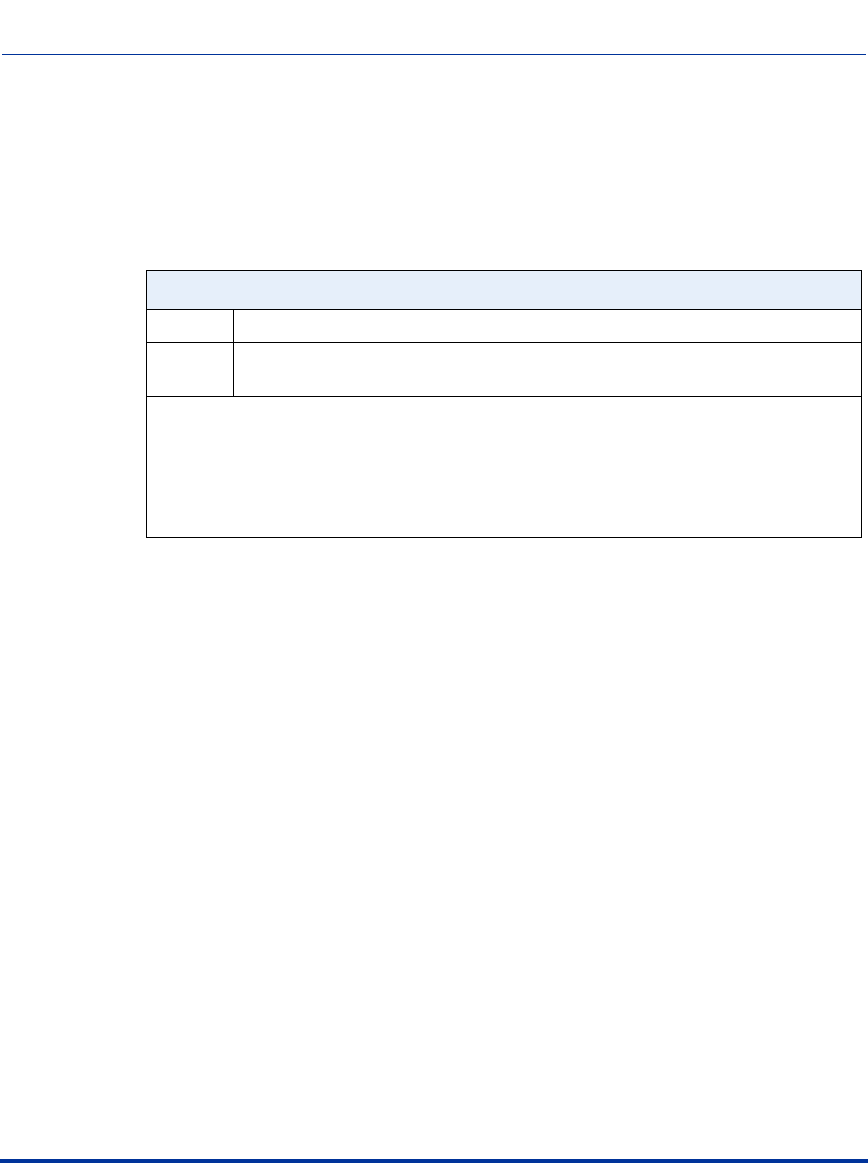
Creating an XML Application
41-001160-03, Rev 00, Release 2.4 F-51
RTPMTx
The RTPMTx URI instructs the phone to transmit a Multicast RTP stream. The
RTPMTx format to use with the AastraIPPhoneExecute object in the URI is:
•RTPMTx:i:p
Where
iSpecifies the Multicast IP Address to which an RTP stream is transmitted.
pSpecifies the UDP port on which to transmit the RTP stream.
Ensure that this is a number greater than 3100.
Example: This example sends a multicast RTP stream to 239.0.1.20 from UDP port
21000.
<AastraIPPhoneExecute>
<ExecuteItem URI = ”RTPMTx:239.0.1.20:21000”>
<AastraIPPhoneExecute>
Draft 1
Creating an XML Application
F-52 41-001160-03, Rev 00, Release 2.4
IP Phone Administrator Guide
Using RTP Recording and Simultaneous Playing
(not supported on 6751i)
The IP Phones allow for RTP recording and simultaneous playing of an audio file
via XML Execute commands. An Administrator can use the RTP and multicast
RTP commands (RTPTx, RTPRx, RTPMTx, RTPMRx) with the
“AastraIPPhoneExecute” object to initiate this feature.
The RTP and multicast RTP commands allow the phone to send/receive an RTP
stream to/from given multicast/unicast addresses (without involving SIP
signaling). An Administrator can use the following two options appended to the
RTP commands for recording and simultaneously playing of an audio file:
•mix - When appended to an RTP command, “mix” enables RTP recording and
simultaneous playing of an audio file.
•disableIcon - When appended to an RTP command, “disableIcon” disables
the display of the mixed call icons on the LCD of the phones.
Sending RTP
When a phone receives a request for sending RTP:
• and there is an existing call on the phone, no new audio session is created; the
existing RTP call (incoming or outgoing) is sent to the receiving party.
• and the phone is already in a 3-way conference, the request is declined.
• and there is no existing call on the phone, a new audio session is created and
the RTP call is sent to the receiving party.
Note: This feature is not supported on the 6751i. Also, if the cordless
handset (CT) and the base phone are connected (Models 9480i CT and
6757i CT), this feature is not supported.
Draft 1
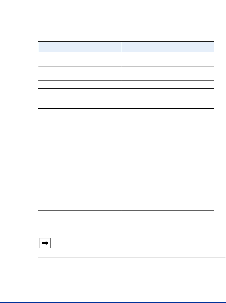
Creating an XML Application
41-001160-03, Rev 00, Release 2.4 F-53
The following scenarios assume that a request for sending mixed RTP is initiated.
Phone State Action When RTP Transmitting
Phone is in idle state. The phone initiates a new RTP session on
the paging line and the paging line displays.
There is an existing voice call on the
phone. The phone starts sending the mixed RTP
stream, paging line does not display.
The phone is in conference. The request for sending RTP is declined.
The phone is not in conference;
however, both voice and conference
streams are busy (cordless handset).
The request for sending RTP is declined.
The phone is in a call using the
conference stream and the voice
stream is free.
Paging call is initiated using the voice
stream with the mixed audio from the
conference stream; paging line does not
display.
The active voice call is dropped.
(Mixed RTP stream was being sent
using this voice call).
RTP stream is dropped.
A new call comes in while an active
voice call is put on hold. (Mixed RTP
stream was being sent using this voice
call).
RTP mixed stream is sent for the currently
active call.
The phone is sending the mixed RTP
stream, and there is an existing voice
call on the phone. A request for
initiating localized conference is
initiated.
Localized conference request is declined,
and the focus is given back to the initiating
line.
Note: When an RTP stream is being sent with RTP recording and
simultaneous playing (mix), the IP Phone LCD displays an icon with an
‘m’ on top to indicate that a mixed RTP stream is being sent.
Draft 1
Creating an XML Application
F-54 41-001160-03, Rev 00, Release 2.4
IP Phone Administrator Guide
Receiving RTP
When a phone receives a request for receiving RTP:
• if there is an existing audio path, (handset, headset, or speakerphone), the
phone uses it to play the incoming RTP stream on top of the existing one.
• if the phone is already in a 3-way conference, the request is declined.
• if there is no existing audio path, the phone creates a new one (speakerphone)
to play the incoming RTP stream
The following scenarios assume that a request for receiving mixed RTP is
initiated.
Phone State Action When RTP Receiving
Phone is in idle state. The phone initiates a new RTP session on
the paging line and the paging line displays.
There is an existing voice call on the
phone. The phone starts playing the incoming RTP
stream on top of the existing call. Paging
line does not display.
The phone is in conference. The request for receiving RTP is declined.
The phone is not in conference;
however, both voice and conference
streams are busy (cordless handset).
The request for receiving RTP is declined.
The phone is in a call using the
conference stream and the voice
stream is free.
Incoming RTP stream is played on top of
the existing voice stream. Paging line does
not display.
The active voice call is dropped. (RTP
stream was being played on top of this
voice call).
RTP stream is dropped.
A new call comes in while an active
voice call is put on hold. (RTP stream
was being played on top of this voice
call).
RTP mixed stream is played on top of the
currently active call.
The active voice call is dropped RTP stream is dropped.
Note: When RTP stream is being received with RTP recording and
simultaneous playing (mix), you can use the volume controls on the IP
phone to adjust the volume (increase or decrease) to your specifications.
Draft 1

Creating an XML Application
41-001160-03, Rev 00, Release 2.4 F-55
Examples
The following are examples of using the “mix” and “disableIcon” execute
commands with the AastraIPPhoneExecute object. These commands apply to
both the RTP and multicast RTP XML commands (RTPTx, RTPRx, RTPMTx,
RTPMRx).
• Send mix unicast RTP stream (if there is existing voice call) to
10.30.100.20:21000. Mix icon is displayed on the phone’s call screen.
<AastraIPPhoneExecute>
<ExecuteItem URI="RTPTx:10.30.100.20:21000:mix">
</AastraIPPhoneExecute>
• Receive unicast RTP stream from 10.30.100.20 at port 21000 with the egress
voice settings at 3 levels more than the current offset and play on top of the
existing voice stream (if any).
<AastraIPPhoneExecute>
<ExecuteItem URI="RTPRx:10.30.100.20:21000:3:mix">
</AastraIPPhoneExecute>
• Receive unicast RTP stream from 10.30.100.20 at port 21000 with the voice
settings as used earlier and play on top of the existing voice call (if any). Also,
the mixing icon is not shown on the call screen.
<AastraIPPhoneExecute>
<ExecuteItem URI="RTPRx:10.30.100.20:21000:mix:disableIcon">
</AastraIPPhoneExecute>
Draft 1

Creating an XML Application
F-56 41-001160-03, Rev 00, Release 2.4
IP Phone Administrator Guide
Using Commands for Playing a WAV File
The IP Phones allow a WAV file to be played or stopped via XML Execute
commands. A WAV file is an audio file format standard for storing an audio bit
stream on a system in raw, uncompressed format or compressed format to reduce
the file size.
A WAV file can be streamed to the phone using the HTTP protocol.
The WAV feature supports the following:
• Streaming of the WAV file to allow it to be locally played
• Allows you to abort the audio streaming by pressing the Goodbye key on the
phone.
• Supports the HTTP file download protocol
• Supports the aLaw and uLaw codecs
• Calls “Action URI INCOMING” when the audio WAV starts, and
“Action URI ONHOOK” when the WAV file playing has completed. The
name of the WAV file is inserted into the Action URI.
• Plays the WAV file only if the phone is idle.
• Aborts streaming if another line is selected for dialing out, or if the current
line is accepting an incoming call.
• WAV audio file starts only when 4 seconds of the audio data (or the complete
file) has been accumulated.
• Follows the standard phone behavior of speaker/head set/hand set.
An Administrator can use two new XML Execute commands with the
AastraIPPhoneExecute object to allow the phones to play a WAV file:
• Wav.Play - This command initiates the streaming of a WAV file to the phone.
•Wav.Stop - This command aborts a WAV streaming.
Draft 1

Creating an XML Application
41-001160-03, Rev 00, Release 2.4 F-57
XML Command: Wav.Play
The Wav.Play XML Execute command starts the streaming of a WAV file. You
enter this command with the AastraIPPhoneExecute object in the following
format:
Wav.Play:http://[username[:password]@]<host>[/<path>]/<file>
The following are examples of using the wav.play command with the XML
Execute object.
Examples
<AastraIPPhoneExecute>
<ExecuteItem URI="Wav.Play:http://10.30.101.26/wavfiles/example.wav" />
<AastraIPPhoneExecute>
<AastraIPPhoneExecute>
<ExecuteItem URI="Wav.Play:http://user:password@10.30.101.26/example.wav" />
<AastraIPPhoneExecute>
XML Command: Wav.Stop
The Wav.Stop Execute command aborts a WAV streaming currently in progress.
You enter this command with the AastraIPPhoneExecute object in the following
format:
Wav.Stop:
Example
<AastraIPPhoneExecute>
<ExecuteItem URI="Wav.Stop:" />
<AastraIPPhoneExecute>
IP Phone UI Screens During WAV Streaming
The 9143i, 6751i, and 6753i LCD screens display the following during WAV
streaming.
Streaming
00:10
Draft 1
Creating an XML Application
F-58 41-001160-03, Rev 00, Release 2.4
IP Phone Administrator Guide
The 9480i, 9480i CT, 6755i, 6757i, and 6757i CT screens display the following
during WAV streaming.
To abort the WAV streaming, a user can press any of the following:
•Goodbye key
•Drop softkey
•Line key (not applicable to the 6751i)
You can also place the handset (if in use) on hook.
Streaming
00:10
Draft 1
Creating an XML Application
41-001160-03, Rev 00, Release 2.4 F-59
Using Commands to Reset Local Data on the Phone
The phones allow XML commands that you can use to delete and reset the
phone’s directory, callers list, redial list, and the local.cfg file. You use these
commands with the AastraIPPhoneExecute object. The following table
identifies the XML commands to reset data on the phone.
Examples
The following examples illustrate the use of the new XML commands to delete
and reset data on the phone. The command is shown in bold.
<AastraIPPhoneExecute>
<ExecuteItem URI="Command: ClearLocal"/>
</AastraIPPhoneExecute>
<AastraIPPhoneExecute>
<ExecuteItem URI="Command: ClearCallersList"/>
</AastraIPPhoneExecute>
<AastraIPPhoneExecute>
<ExecuteItem URI="Command: ClearDirectory"/>
</AastraIPPhoneExecute>
<AastraIPPhoneExecute>
<ExecuteItem URI="Command: ClearRedialList"/>
</AastraIPPhoneExecute>
XML Command Description
Command: ClearLocal • Deletes the local.cfg file
• Displays a "Resetting" message to the
IP Phone UI
• Resets the phone
Command: ClearCallersList • Deletes the Callers List
• Clears any missed call messages
Command: ClearDirectory • Deletes the Directory
Command: ClearRedialList • Deletes the Redial List
Note: The XML commands to reset local data on the phone are not
applicable to the Model CT handsets.
Draft 1
Creating an XML Application
F-60 41-001160-03, Rev 00, Release 2.4
IP Phone Administrator Guide
XML URI for Key Press Simulation
The phones provide a feature that allow an XML Developer or Administrator to
define XML Key URIs that can send key press events to the phone, just as if the
physical hard key, softkey, or programmable key were pressed on the phone.
When the Key URI event is sent from the server to the phone, the phone initiates
the event as if the key was physically pressed. If the key is not present on the
phone (hard key) or not available (softkey or programmable key), when the phone
receives the URI, the event is discarded. If you are in the process of changing the
softkey or programmable key setting, or the key is disabled while the event is
being processed, the request is discarded. The phone maps key events to it’s
physical keys and not to it’s mapped logical keys.
The following table identifies the XML URIs for pressing buttons on the phone..
XML Key URI Description
Line Keys
Key:Line1 to Key:Line4 Line 1 to 4 Keys
Note: The phone ignores URI line keys 5 to
9 since it does not have Line 5 to 9 physical
keys.
Keypad Keys
Key:KeyPad0 to Key:KeyPad9 Numeric Keypad Keys 0-9
Key:KeyPadStar * - Star Key
Key:KeyPadPound # Hash Key
Softkeys
Key:SoftKey1 to Key:SoftKey<n> Softkey 1 to <n> (valid softkeys depend on
the number of physical softkeys on the
phone)
Key:TopSoftKey1 to Key:TopSoftKey<n>
top Top softkeys 1 to <n> ((valid top softkeys
depend on the number of physical top
softkeys on the phone)
Programmable Keys
Key:PrgKey1 to Key:PrgKey<n> Programmable keys 1 to <n> (valid
programmable keys depend on the number
of physical programmable keys on the
phone)
Draft 1
Creating an XML Application
41-001160-03, Rev 00, Release 2.4 F-61
Expansion Module Keys
Key:ExpMod1SoftKey1 to
Key:ExpMod1SoftKey60 Expansion module 1 softkeys 1 to 60
Note: The phone ignores URI expansion
module key events if the keys are not
physically present on the expansion
module.
Key:ExpMod2SoftKey1 to
Key:ExpMod2SoftKey60 Expansion module 2 soft keys 1 to 60
Key:ExpMod3SoftKey1 to
Key:ExpMod3SoftKey60 Expansion module 3 soft keys 1 to 60
Volume Key
Key:VolDwn Volume Decrease Key
Key:VolUp Volume Increase Key
Feature Keys
Key:Xfer Transfer Key
Key:Conf Conference Key
Key:Services Services Key
Key:Intercom Intercom Key
Key:Headset Headset Key
Note: For Headset URI key, the behavior
will be as if the "speaker/headset" key is
pressed; and does not switch to headset for
headset key event or to speaker for speaker
key event.
Key:Speaker Speaker Key
Note: For Speaker URI key, the behavior
will be as if the "speaker/headset" key is
pressed; and does not switch to headset for
headset key event or to speaker for speaker
key event.
Key:Mute Mute Key
Key:Hold Hold Key
Key:Redial Redial Key
Key:Callers Callers Key
XML Key URI Description
Draft 1
Creating an XML Application
F-62 41-001160-03, Rev 00, Release 2.4
IP Phone Administrator Guide
Examples
There are two ways to format the XML key URI:
For XML Post Messages
<ExecuteItem URI="<XML Key URI>" />
Example: <ExecuteItem URI="Key: Line1" />
Key:Directory Directory Key
Key:Options Options Key
Key:Save Save Key
Key:Delete Delete Key
Key:Swap Swap Key
Key:Goodbye GoodBye Key
Navigation Keys
Key:NavUp Navigation Up Key
Key:NavDwn Navigation Down Key
Key:NavLeft Navigation Left Key
Key:NavRight Navigation Right Key
Function Keys (only if physically configured on the phone or expansion module)
KeyPark Park Softkey
KeyPickup Pickup Softkey
Notes:
1. If the URI key is a valid key, the phone executes the key regardless
of the current state on the phone.
2. Park and Pickup XML URI softkeys are available ONLY if these
features are physically configured on the phone or expansion module.
XML Key URI Description
Draft 1

Creating an XML Application
41-001160-03, Rev 00, Release 2.4 F-63
For XML Key Scripts
<URI><XML Key URI></URI>
Example: <URI>Key: Line1</URI>
<SoftKey index="1">
<Label>Keypad1</Label>
<URI>Key: Line1</URI>
</SoftKey>
Draft 1

Creating an XML Application
F-64 41-001160-03, Rev 00, Release 2.4
IP Phone Administrator Guide
Dynamic Configuration Object (to push a configuration to the phone)
The IP phones provide an XML feature that allows you to make configuration
changes to the phone that take affect immediately, without having to reboot the
phone. This feature involves creating XML scripts that push the changed
configuration parameter(s) from the server to the IP phones.
You can use the AastraIPPhoneConfiguration object in the XML scripts to
change configuration parameters or configure new parameters. However, since the
IP phone does not save new parameters created in XML scripts to the local.cfg
file, when the phone reboots, it does not save the new parameters on the phone. In
order for the phone to apply new configuration parameters, you have to enter the
parameters via the user interfaces (Telephone User Interface, Web User Interface,
or configuration files), or reapply the new parameters using the XML scripts after
every boot.
Specific configuration parameters are dynamic on the phone when pushed from
XML scripts on the server. For more information about dynamic configuration
parameters contact Aastra Technical Support.
AastraIPPhoneConfiguration Object Structure
The AastraIPPhoneConfiguration object describes the structure of the XML
document that you can use to push the configuration to the IP phone. The basic
structure of the AastraIPPhoneConfiguration object is:
<AastraIPPhoneConfiguration>
<ConfigureItem>
<Parameter>Parameter name</Parameter>
<Value>Parameter value</Value>
</ConfigureItem>
<ConfigureItem>
<Parameter>Parameter name</Parameter>
<Value>Parameter value</Value>
</ConfigureItem>
.
.
.
<AastraIPPhoneConfiguration>
Draft 1

Creating an XML Application
41-001160-03, Rev 00, Release 2.4 F-65
XML Example:
The following is an example of an XML configuration script that creates a softkey
you can press on the IP phone to push the configuration from the server to the
phone:
<AastraIPPhoneConfiguration>
<ConfigureItem>
<Parameter>softkey1 label</Parameter>
<Value>John Doe</Value>
</ConfigureItem>
<ConfigureItem>
<Parameter>softkey1 type</Parameter>
<Value>speeddial</Value>
</ConfigureItem>
<ConfigureItem>
<Parameter>softkey1 value</Parameter>
<Value>5551234</Value>
</ConfigureItem>
</AastraIPPhoneConfiguration>
Note: You can add more configuration items as applicable. There is a
limit of 5000 bytes (less than 5k) on the size of XML configuration
objects.
Draft 1

Creating an XML Application
F-66 41-001160-03, Rev 00, Release 2.4
IP Phone Administrator Guide
SetType Attribute Used with Configuration Object
The IP phones include an attribute, “setType”, to be used with the
AastraIPPhoneConfiguration XML object. The AastraIPPhoneConfiguration
object allows you to make configuration changes to the phone that take affect
immediately, without having to reboot the phone. The “setType” attribute
enhances the ability of the AastraIPPhoneConfiguration object to override locally
set configuration parameters, and parameters that persist across a reboot, allowing
the user to control how the configuration parameters are saved (locally, remotely,
or override).
The following table describes the values you can use with the “setType” attribute.
Values for “setType” Parameter Description
remote (default) Allows the configuration parameters to be
saved with the same precedence as the
server settings. This setting does not persist
through a reboot.
Note: This was the behavior of the phone
prior to Release 2.4.
local Allows the configuration parameters to be
saved with the same precedence as if you
configured them using the IP Phone UI or
Aastra Web UI. This setting persists
through reboots of the phone. The only way
to change this setting is via the IP Phone
UI, Aastra Web UI, or another local type
setting.
override Allows the configuration parameters to be
saved with the same precedence as server
settings. This setting does not persist
through a reboot and removes the local
setting.
Draft 1

Creating an XML Application
41-001160-03, Rev 00, Release 2.4 F-67
The following are examples of using the the “remote”, “local”, and “override”
values with the setType attribute and the AastraIPPhoneConfiguration object.
Remote Setting Examples (default)
The following are examples that are the same as using setType=”remote” setting
for a specific configuration item (softkey1 label).
<AastraIPPhoneConfiguration>
<ConfigurationItem>
<Parameter>softkey1 label</Parameter>
<Value>Test</Value>
</ConfigurationItem>
</AastraIPPhoneConfigutation>
or
<AastraIPPhoneConfiguration setType="remote">
<ConfigurationItem>
<Parameter>softkey1 label</Parameter>
<Value>Test</Value>
</ConfigurationItem>
</AastraIPPhoneConfigutation>
RESULT: If the value for "softkey1 label" is not specified via the configuration
files, or another setType="remote" setting, the XML examples shown above
assign the value of "Test". This value is lost when the phone reboots. If the value
for "softkey1 label" has been specified locally, these XML examples do not
change that value.
Notes:
1. If you enter a value for the “setType” attribute in the root tag of the
AastraIPPhoneConfiguration object, the setting affects all of the
configuration parameters and their sub-elements.
2. If you enter a value for the “setType” attribute for a single
configuration item, the setting affects on that configuration item and its
sub-elements.
Draft 1

Creating an XML Application
F-68 41-001160-03, Rev 00, Release 2.4
IP Phone Administrator Guide
Local Setting Example
The following is an example of using the setType=”local” setting for a specific
configuration item (softkey1 label).
<AastraIPPhoneConfiguration setType="local">
<ConfigurationItem>
<Parameter>softkey1 label</Parameter>
<Value>Test</Value>
</ConfigurationItem>
</AastraIPPhoneConfigutation>
RESULT: The value of "softkey1 label" is set to "Test". This value persists
through reboots of the phone.
Override Setting Example
The following is an example of using the setType=”override” setting for a
specific configuration item (softkey1 label)
<AastraIPPhoneConfiguration setType="override">
<ConfigurationItem>
<Parameter>softkey1 label</Parameter>
<Value>Test</Value>
</ConfigurationItem>
</AastraIPPhoneConfigutation>
RESULT: The value of "softkey1 label" is set to "Test". When the phone reboots,
the value for the "softkey1 label" reverts back to the server configured value, or its
default value on the server.
Draft 1

Creating an XML Application
41-001160-03, Rev 00, Release 2.4 F-69
Example of Using Multiple “setType” Values
The following is an example of using multiple “setType” values for mutitple
configuration items (softkey1, softkey2).
<AastraIPPhoneConfiguration setType="local">
<ConfigurationItem>
<Parameter>softkey1 label</Parameter>
<Value>Test</Value>
</ConfigurationItem>
<ConfigurationItem setType="override">
<Parameter>softkey2 label</Parameter>
<Value>Test</Value>
</ConfigurationItem>
</AastraIPPhoneConfigutation>
RESULT: The value of “Test” is set for "softkey2 label" using the local rules.
The value of “Test” is set for "softkey3 label” using the override rules. When all
items have been set, the phone reboots.
Limitation
The following is a limitation for the “setType” attribute:
•Using setType=”local” to set a parameter that is not modifiable via the IP
Phone UI or the Aastra Web UI, results in a parameter that can only be
changed via XML.
Draft 1
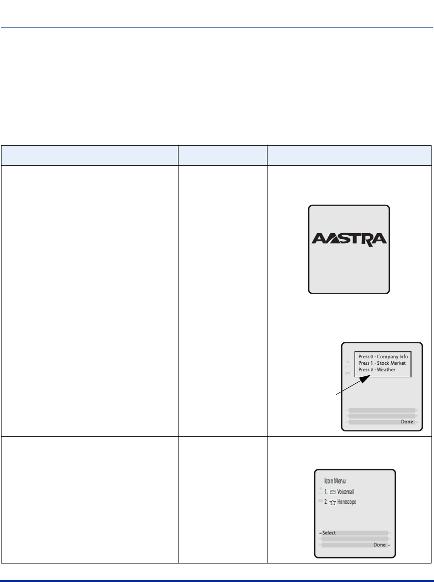
Creating an XML Application
F-70 41-001160-03, Rev 00, Release 2.4
IP Phone Administrator Guide
XML Image Objects (9480i, 9480i CT, 6755i, 6757i/6757i CT only)
The 9480i/9480i CT, 6755i, and 6757i/6757i CT IP phones provide an XML
feature that allows you to load images in XML applications that display to the
LCD screen. The following table describes the three types of image objects that
you can use in an XML script:
XML Image Object Image Type Description
AastraIPPhoneImageScreen Standalone Bitmap
Image Displays a single bitmap image
according to alignment, height, and
width specifications.
AastraIPPhoneImageMenu Menu Image Displays a bitmap image as a menu.
Menu selections are linked to keypad
keys (0-9, *, #).
AastraIPPhoneTextMenu (Icon Menu) Icon Menu Image Displays a small icon before each item
in the menu.
This entire box is
a bitmap image.
Draft 1

Creating an XML Application
41-001160-03, Rev 00, Release 2.4 F-71
You can include images with an XML object in two ways:
• Using pixel data stored with specified tags
• Using an internal bitmap loaded via a specified URI
The following paragraphs describe each of the image objects and how you can use
them in the XML scripts.
AastraIPPhoneImageScreen Object
The AastraIPPhoneImageScreen object displays an image as a single bitmap
image on the LCD screen. You can specify the placement of the image on the
screen by setting the following attributes:
• verticalAlign
• horizontalAlign
•height
•width
The image is specified as a series of hexadecimal characters. Two hex characters
map to one byte of pixel data, where each bit represents a pixel. The image data
describes the bitmap from left to right and top to bottom. The data is padded on
an 8-bit boundary, so if the height and width do not match the pixel information,
then the image will not display correctly. The character strings map to the middle
and four corners of the screen. If desired, you can specify an integer as an absolute
pixel for customized displays.
Note: The actual resolution of the image on the LCD screen is dependent
on the phone model. The 6755i screen has a resolution of 144 x 75 pixels.
The 6757i/6757i CT screens have a resolution of 144 x 128 pixels.
However, the display of the image is limited to 40 x 144 pixels high.
Note: A special URI of "Image:Logo" is used to load the current logo
bitmap for the phone (Aastra or branded). In this case, the height and
width can be ignored.
Draft 1

Creating an XML Application
F-72 41-001160-03, Rev 00, Release 2.4
IP Phone Administrator Guide
XML Example:
The XML script for the AastraIPPhoneImageScreen object is as follows:
<AastraIPPhoneImageScreen>
<Image verticalAlign = "top,middle,bottom,'pixel'",
horizontalAlign = "left,middle,right,'pixel'"
height="'integer'", width="'integer'">
FF00F800FF00FFFFFFFFFFFF00FF00FF00FFF8F200
</Image>
<!-vertical and horizontal default to "middle" ->
<!-height and width must match the image data ->
</AastraIPPhoneImageScreen>
XML Screen Example:
Note: This object supports the destroyOnExit attribute.
Draft 1

Creating an XML Application
41-001160-03, Rev 00, Release 2.4 F-73
AastraIPPhoneImageMenu
The AastraIPPhoneImageMenu object allows you to use a bitmap image to
display as a menu. Each menu item is linked to a keypad key (0-9, *, #). You can
use this type of image object when you want to display menu choices as a
non-ASCII character set or with pictures only. You can specify the placement of
the image on the screen by setting the following attributes:
• verticalAlign
• horizontalAlign
•height
•width
The image is specified as a series of hexadecimal characters. Two hex characters
map to one byte of pixel data, where each bit represents a pixel. The image data
describes the bitmap from left to right and top to bottom. The data is padded on
an 8-bit boundary, so if the height and width do not match the pixel information,
then the image will not display correctly. The character strings map to the middle
and four corners of the screen. If desired, you can specify an integer as an absolute
pixel for customized displays.
XML Example:
The XML script for the AastraIPPhoneImageMenu object is as follows:
<AastraIPPhoneImageMenu>
<Image verticalAlign = "top,middle,bottom,'pixel'",
horizontalAlign = "left,middle,right,'pixel'"
height="'integer'", width="'integer'">
FF00F800FF00FFFFFFFFFFFF00FF00FF00FFF8F200
</Image>
<!-Base attribute is optional-->
<URIList base = "http://someserver/">
<URI key = "0">link1.php</URI>
<URI key = "1">link2.php</URI>
<URI key = "#">link3.php</URI>
</URIList>
</AastraIPPhoneImageMenu>
Draft 1
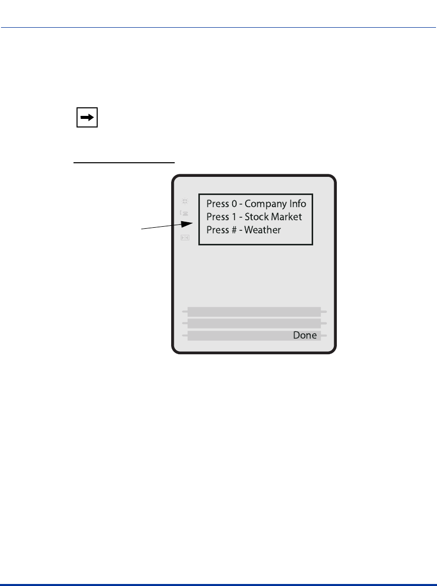
Creating an XML Application
F-74 41-001160-03, Rev 00, Release 2.4
IP Phone Administrator Guide
Each URI is appended to the “base” URI if one exists. The default softkey is a
“Done” key at the bottom right position. It is a parse error if two URIs specify the
same index.
XML Screen Example:
Note: This object supports the destroyOnExit attribute.
This entire box is
a bitmap image.
Draft 1

Creating an XML Application
41-001160-03, Rev 00, Release 2.4 F-75
AastraIPPhoneTextMenu (Icon Menu)
The AastraIPPhoneTextMenu (Icon Menu) object is identical to the “Text Menu
Object (Menu Screens)” described on page F-6, except a small icon image appears
after the menu number and before the text item. The Text Menu object allows
application developers to create a numerical list of menu items on the IP phones.
The AastraIPPhoneTextMenu (Icon Menu) object allows users to navigate the
application, by linking HTTP requests and icons to menu items.
XML Example:
The XML script for the AastraIPPhoneTextMenu (Icon Menu) object is as
follows:
<AastraIPPhoneTextMenu>
<Title> Icon Menu </Title>
<MenuItem base = http://someserver/,
icon="1">
<Prompt> Voicemail </Prompt>
<URI>scripts/voicemail.php</URI>
</MenuItem>
<MenuItem icon="2">
<Prompt> Horoscope</Prompt>
<URI> scripts/horoscope.php </URI>
</MenuItem>
<IconList>
<Icon index = "1"> Icon:Envelope </Icon>
<Icon index = "2"> FFFF0000FFFF0000 </Icon>
</IconList>
</AastraIPPhoneTextScreen>
The “icon=1” attribute in the above example tells the phone to display the icon
specified in the IconList called “<Icon index = “1”> Icon:Envelope </Icon>”.
For more information about the “IconList”, see “Using the <IconList>” on
page F-76.
Draft 1
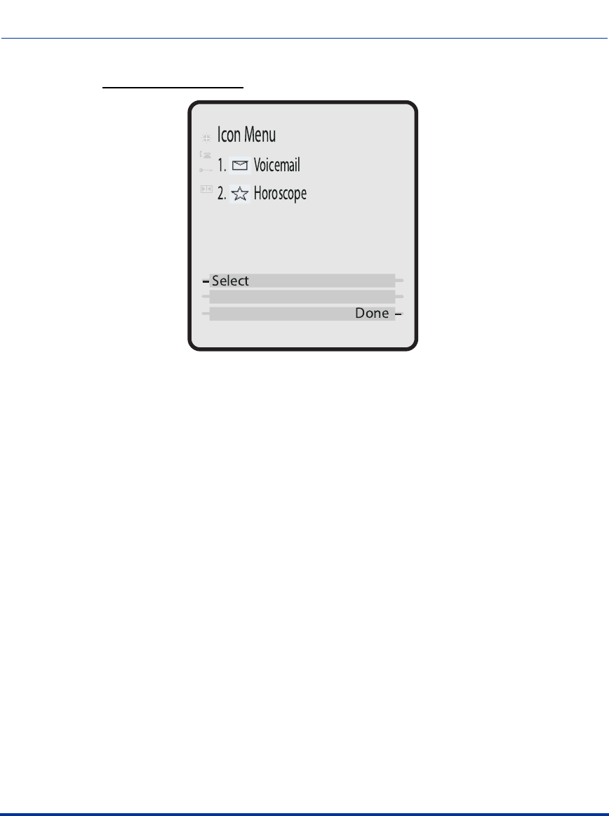
Creating an XML Application
F-76 41-001160-03, Rev 00, Release 2.4
IP Phone Administrator Guide
XML Screen Example:
Using the <IconList>
You can incorporate the use of an <IconList> attribute in the XML script to
define the images you will use with the AastraIPPhoneTextMenu object. After
you define the icons in the <IconList>, you can then call those icons as you need
them throughout the script. This also allows you to assign the icons to softkeys on
the phone.
You can load images in the <IconList> in two ways:
• By specifying the image after a special prefix called “Icon:”
For example:
<IconList>
<Icon index = “1”> Icon:Envelope </Icon>)
<IconList>
• By specifying the image in hexidecimal format
For example:
<IconList>
<Icon index = “2”> FF00F3 </Icon>)
<IconList>
Draft 1

Creating an XML Application
41-001160-03, Rev 00, Release 2.4 F-77
You can use one or both ways to load images within the same XML script. The
softkey icons display at the edge of the screen. Any XML object that supports
softkeys can support the optional <IconList> tag.
XML Example:
The following example illustrates the use of the <IconList> attribute to create
images for softkey prompts.
<AastraIPPhoneTextScreen>
<Title> Directory List </Title>
<Text> Welcome to the Directory. </Text>
<SoftKey index = "4" icon="2">
<Label> Listing </Label>
<URI> http://server/page.php </URI>
</SoftKey>
<SoftKey index = "3" icon="1">
<Label> Exit </Label>
<URI> http://server/otherpage.php </URI>
</SoftKey>
<IconList>
<Icon index = "1"> FF00F3 </Icon>
<Icon index = "2"> Icon:ArrowRight </Icon>
</IconList>
</AastraIPPhoneTextScreen>
Note: For a list of icons that are internal to the IP phone when specifying
the “Icon:<uri name>”, see the section “IP Phone Internal Icon Images”
on page F-78.
Draft 1
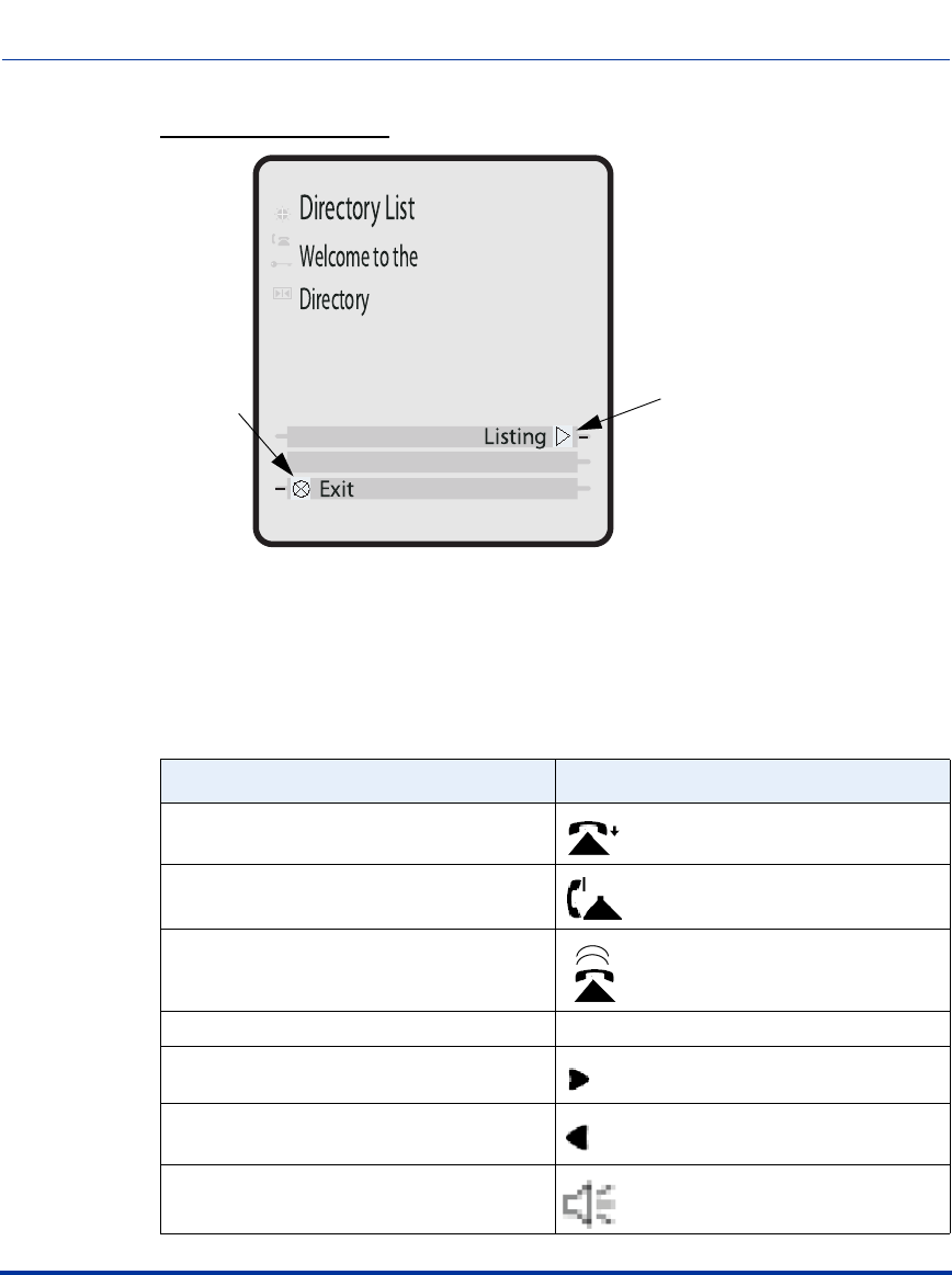
Creating an XML Application
F-78 41-001160-03, Rev 00, Release 2.4
IP Phone Administrator Guide
XML Screen Example:
IP Phone Internal Icon Images
The IP phones have internal icon images you can use when specifying the
“Icon:<uri name>” attribute in the <IconList>. The following table lists the
internal icons you can specify.
URI Name Displays this:
PhoneOnHook
PhoneOffHook
PhoneRinging
DND None
ArrowRight
ArrowLeft
Speaker
Exit Icon ArrowRight Icon
Draft 1
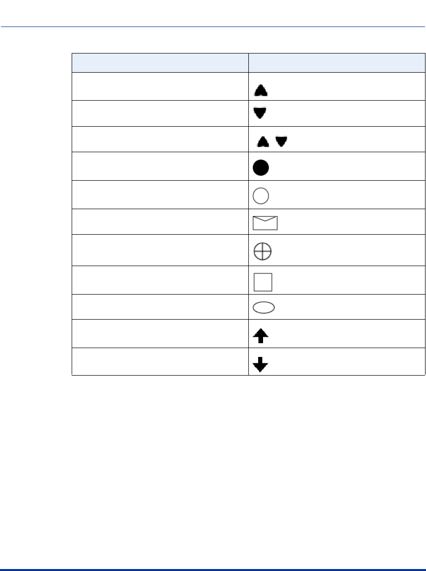
Creating an XML Application
41-001160-03, Rev 00, Release 2.4 F-79
ArrowUp
ArrowDown
ArrowsUpandDown
FilledCircle
EmptyCircle
Envelope
Prohibit
Square
Ellipse
TailArrowUp
TailArrowDown
URI Name Displays this:
Draft 1

Creating an XML Application
F-80 41-001160-03, Rev 00, Release 2.4
IP Phone Administrator Guide
Attributes/Options to Use with XML Objects
Beep Attribute
(configurable via XML objects, config files, or Aastra Web UI)
You can enable or disable a “Beep”option to indicate a status on the phone using
the Status Message object (AastraIPPhoneStatus), the configuration files, or the
Aastra Web UI.
When the phone receives a status message, the BEEP notifies the user that the
message is displaying. The following attribute in the AastraIPPhoneStatus object
enables/disables the BEEP from being heard:
< AastraIPPhoneStatus Beep="yes|no"> (case sensitive)
This attribute is optional. If notification is required, the attribute must be in the
ROOT. If the BEEP attribute is set to "yes" (i.e. Beep="yes") then it is an
indication to the phone to sound a beep when it receives the object. If the Beep
attribute is set to "no" (i.e. Beep="no") or not present, then the default behavior is
no beep is heard when the object arrives to the phone.
Scroll Delay Option
(configurable via config files and Aastra Web UI only)
The IP phones support a scroll delay option that allows you to set the time delay,
in seconds, between the scrolling of each status message on the phone. The default
time is 5 seconds for each message to display before scrolling to the next message.
You can configure this option via the configuration files or the Aastra Web UI.
Changes are dynamic and apply to the phone immediately.
Note: For enabling/disabling a status message beep using the
configuration files and the Aastra Web UI, see Chapter 5, the section,
“Enabling/Disabling a Beep for Status Message Displays.”.
Note: The value set in the configuration files and Aastra Web UI override
the attribute you specify for the AastraIPPhoneStatus object.
Note: For more information about setting the scroll delay option, see
Chapter 5, the section, “Scroll Delay Option for Status Messages.”
Draft 1

Creating an XML Application
41-001160-03, Rev 00, Release 2.4 F-81
Timeout Attribute
(configurable via XML objects only)
The XML “Timeout” attribute allows you to specify a timeout value for the LCD
screen display. You must use the “Timeout” aattribute in the ROOT. When the
phone receives an XML object with this attribute, it overrides the default 45
second timeout specified for custom applications. Setting the “Timeout” attribute
to zero (0) disables this feature.
XML Example:
The following example illustrates the use of the “Timeout” attribute with the
AastraIPPhoneFormattedTextScreen object. The result would cause the LCD
screen to timeout in 30 seconds.
<xs:element name="AastraIPPhoneFormattedTextScreen">
<xs:attribute name="Beep" default="no">
<xs:simpleType>
<xs:restriction base="xs:string>
<xs:pattern value="yes|no"/>
</xs:restriction>
</xs:simpleType>
</xs:attribute>
<xs:attribute name="DestroyOnExit" default="no">
<xs:simpleType>
<xs:restriction base="xs:string>
<xs:pattern value="yes|no"/>
</xs:restriction>
</xs:simpleType>
</xs:attribute>
<xs:AastraIPPhoneFormattedTextScreen Timeout= “30" default = “45”>
<xs:simpleType>
<xs:restriction base="xs:number/>
</xs:simpleType>
</xs:attribute>
Draft 1

Creating an XML Application
F-82 41-001160-03, Rev 00, Release 2.4
IP Phone Administrator Guide
LockIn Attribute
(configurable via XML objects only)
The XML “LockIn” attribute allows you to specify whether or not the
information on the LCD screen stays displayed when other events occur (such as
pressing buttons on the keypad).
You must use the “LockIn” aattribute in the ROOT. The settings for the LockIn
attribute are “Yes” for enabled, and “No” for disabled.
XML Example:
The following example illustrates the use of the “LockIn” attribute with the
AastraIPPhoneFormattedTextScreen object. The result would cause the LCD
screen to lock in the display of the XML information even if other events occur
(except for an incoming call).
<xs:element name="AastraIPPhoneFormattedTextScreen">
<xs:attribute name="Beep" default="no">
<xs:simpleType>
<xs:restriction base="xs:string>
<xs:pattern value="yes|no"/>
</xs:restriction>
</xs:simpleType>
</xs:attribute>
<xs:attribute name="DestroyOnExit" default="no">
<xs:simpleType>
<xs:restriction base="xs:string>
<xs:pattern value="yes|no"/>
</xs:restriction>
</xs:simpleType>
</xs:attribute>
<xs:AastraIPPhoneFormattedTextScreen LockIn= “yes” default="no">
<xs:simpleType>
<xs:restriction base="xs:string>
<xs:pattern value="yes|no"/>
</xs:restriction>
</xs:simpleType>
</xs:attribute>
Note: This attribute is ignored during incoming calls. If this attribute is
set, and the phone receives an incoming call, the LCD screen exits the
XML information and displays the information about the incoming call.
Draft 1

Creating an XML Application
41-001160-03, Rev 00, Release 2.4 F-83
CancelAction Attribute
(configurable via XML objects only)
The XML “cancelAction” attribute allows you to specify a URI that a GET is
executed on when the user presses the default CANCEL key.
You can add this optional feature at the end of any of the XML objects. The
format is:
<Hardkey> action="Cancel">
<Label>Label to Display</Label>
<URI>URI to Get</Label>
</Hardkey>
XML Example:
The following illustrates the AastraIPPhoneTextScreen object using the “Cancel”
attribute:
<AastraIPPhoneTextScreen> cancelAction=”http://10.50.10.117/
ft.xml”>
<Title>Test</Title>
<Text>This is a test of the cancel action</Text>
</AastraIPPhoneTextScreen>
When this XML script is sent to the phone, and the user presses the default
CANCEL key, the script executes a GET on http://10.50.10.117/ft.xml.
Note: The URI must be fully qualified.
Note: If the “cancelAction” attribute was not used in the above script,
then pressing the CANCEL key would simply cancel the current screen.
Draft 1

Creating an XML Application
F-84 41-001160-03, Rev 00, Release 2.4
IP Phone Administrator Guide
HTTP Post
In addition to initiating a request to an XML application from the Services menu,
an HTTP server can push an XML object to the phone via HTTP Post. The phone
parses this object immediately upon receipt and displays the information to the
screen.
The HTTP post packet must contain an "xml=" line in the message body. The
string to parse is located after the equals sign in the message. HTML forms that
post objects to the phone must use a field named "xml" to send their data. See the
following examples (Example 1 and Example 2) for a sample HTTP post packet
and php source code.
Example 1:
POST / HTTP/1.1
Accept: image/gif, image/x-xbitmap, image/jpeg, image/pjpeg,
application/vnd.ms-powerpoint,
application/vnd.ms-excel, application/msword,
application/x-shockwave-flash, */*
Referer: http://10.50.10.53
Accept-Language: en-us..Content-Type: application/
x-www-form-urlencoded
Accept-Encoding: gzip, deflate..User-Agent: Mozilla/4.0
(compatible;MSIE 6.0;
Windows NT 5.0; .NET CLR 1.1.4322)
Host: 10.50.10.49
Content-Length: 194..Connection: Keep-Alive
Cache-Control: no-cache..Authorization: Basic YWRtaW46MjIyMjI=
xml=%3CAastraIPPhoneTextScreen%3E%
%3CTitle%3E6757i+Tester%3C%2FTitle%3E
%3CText%3EMessage+to+go+on+phone.++Limit+to+512+bytes.%3C%2FText%3E
%2FAastraIPPhoneTextScreen%3E%
Note: The XML object cannot be larger than 2150 bytes. The phone
denies any posts larger than this limit.
Draft 1

Creating an XML Application
41-001160-03, Rev 00, Release 2.4 F-85
Example 2:
Below is a sample php source code which sends an XML object to an Aastra
phone.
<?php
#
function push2phone($server,$phone,$data)
{
# url-encode the xml object
$xml = "xml=".urlencode($data);
$post = "POST / HTTP/1.1\r\n";
$post .= "Host: $phone\r\n";
$post .= "Referer: $server\r\n";
$post .= "Connection: Keep-Alive\r\n";
$post .= "Content-Type: application/x-www-form-urlencoded\r\n";
$post .= "Content-Length: ".strlen($xml)."\r\n\r\n";
$fp = @fsockopen ( $phone, 80, $errno, $errstr, 5);
if($fp)
{
@fputs($fp, $post.$xml);
flush();
fclose($fp);
}
}
##############################
$xml = "<AastraIPPhoneTextScreen>\n";
$xml .= "<Title>Push test</Title>\n";
$xml .= "<Text>This is a test for pushing a screen to a phone </
Text>\n";
$xml .= "</AastraIPPhoneTextScreen>\n";
push2phone("172.16.96.63',"172.16.96.75",$xml);
?>
Draft 1

Creating an XML Application
F-86 41-001160-03, Rev 00, Release 2.4
IP Phone Administrator Guide
HTTP Refresh Header
You can use an HTTP refresh header with the XML screen objects on the IP
phones. This feature provides the following:
• All current XML screen objects have the ability to be refreshed by adding a
Refresh and URL setting to the HTTP headers. (see Refresh setting format
below)
• The Refresh setting is set by the XML application and it is up to the
application to decide which objects it wants to refresh.
The Refresh setting must be included in the HTTP header. The XML application
decides which objects it wants to use with this setting. The phone recognizes this
setting when parsing the HTTP header. If the setting is present, then it passes
along the refresh timeout and the URL to the ParserData object, which all XML
screen objects inherit from. The ParserData class also has a timer, which must be
set to expire at the next refresh time. When the timer expires (time to refresh the
screen), the phone requests the URL again and displays the refreshed screen.
Refresh Setting Format
The following is the Refresh setting format for the HTTP header:
Refresh: <timeout>; URL=<page to load>
The following example is a Refresh setting for use in an HTTP header:
Refresh: 3; URL=http://10.50.10.140/cgi-bin/update.xml
Note: This HTTP refresh header feature only applies to objects that
display to the screen.
Note: You must use the Refresh and URL parameters in order for this
feature to work in the HTTP header.
Draft 1

Creating an XML Application
41-001160-03, Rev 00, Release 2.4 F-87
HTTP Language Header
You can use an HTTP language header with the XML screen objects on the IP
phones. By including the language information in the HTTP header, the HTTP
GET includes the phone model, the firmware and the MAC address of the phone.
When the user selects a language on the phone, the selected language is sent to the
XML application and the application displays to the screen in that language.
XML Schema File
After creating an XML application for your IP phone, you can validate the XML
objects using the Schema file provided in this section. This helps you find any
parsing errors that may exist, and verify that your XML objects conform to the
Aastra API.
XML Schema
<?xml version="1.0" encoding="ISO-8859-1" ?>
<xs:schema xmlns:xs="http://www.w3.org/2001/XMLSchema">
<xs:element name="AastraIPPhoneTextScreen">
<xs:complexType>
<xs:sequence>
<xs:element name="Title" type="xs:string" />
<xs:element name="Text">
<xs:simpleType>
<xs:restriction base="xs:string">
<xs:minLength value="1" />
<xs:maxLength value="1000" />
</xs:restriction>
</xs:simpleType>
</xs:element>
</xs:sequence>
Note: This HTTP language header feature only applies to objects that
display to the screen.
Note: Aastra IP phonees do not contain validating XML parsers. There
are many free XML validators available on the Web
(i.e., http://apps.gotdotnet.com/xmltools/xsdvalidator/Default.aspx) that
can perform validation using the schema file.
Draft 1

Creating an XML Application
F-88 41-001160-03, Rev 00, Release 2.4
IP Phone Administrator Guide
<xs:AastraIPPhoneTextScreen LockIn="yes" default="no">
<xs:simpleType>
<xs:restriction base="xs:string>
<xs:pattern value="yes|no"/>
</xs:restriction>
</xs:simpleType>
</xs:attribute>
<xs:AastraIPPhoneTextScreen Timeout="30" default="45">
<xs:simpleType>
</xs:complexType>
</xs:element>
<xs:element name="AastraIPPhoneTextMenu">
<xs:complexType>
<xs:sequence>
<xs:element name="Title" type="xs:string" />
<xs:element name="MenuItem" minOccurs="1" maxOccurs="15">
<xs:complexType>
<xs:sequence>
<xs:element name="Prompt" type="xs:string" />
<xs:element name="URI" type="xs:string" />
</xs:sequence>
<xs:attribute name="base" type="xs:string" />
</xs:complexType>
</xs:element>
</xs:sequence>
<xs:attribute name="destroyOnExit" default="no">
<xs:simpleType>
<xs:restriction base="xs:string">
<xs:pattern value="yes|no" />
</xs:restriction>
</xs:simpleType>
</xs:attribute>
</xs:complexType>
</xs:element>
<xs:element name="AastraIPPhoneInputScreen">
<xs:complexType>
<xs:sequence>
<xs:element name="Title" />
<xs:element name="Prompt" />
<xs:element name="URL" />
<xs:element name="Parameter" />
<xs:element name="Default" />
</xs:sequence>
<xs:attribute name="type">
<xs:simpleType>
Draft 1

Creating an XML Application
41-001160-03, Rev 00, Release 2.4 F-89
<xs:restriction base="xs:string">
<xs:pattern value="IP|string|number" />
</xs:restriction>
</xs:simpleType>
</xs:attribute>
<xs:attribute name="password" default="no">
<xs:simpleType>
<xs:restriction base="xs:string">
<xs:pattern value="yes|no" />
</xs:restriction>
</xs:simpleType>
</xs:attribute>
<xs:attribute name="destroyOnExit" default="no">
<xs:simpleType>
<xs:restriction base="xs:string">
<xs:pattern value="yes|no" />
</xs:restriction>
</xs:simpleType>
</xs:attribute>
</xs:complexType>
</xs:element>
<xs:element name="AastraIPPhoneDirectory">
<xs:complexType>
<xs:sequence>
<xs:element name="Title" type="xs:string" />
<xs:element name="MenuItem" minOccurs="1" maxOccurs="15">
<xs:complexType>
<xs:sequence>
<xs:element name="Prompt" type="xs:string" />
<xs:element name="URI" type="xs:string" />
</xs:sequence>
</xs:complexType>
</xs:element>
</xs:sequence>
<xs:attribute name="destroyOnExit" default="no">
<xs:simpleType>
<xs:restriction base="xs:string">
<xs:pattern value="yes|no" />
</xs:restriction>
</xs:simpleType>
</xs:attribute>
<xs:attribute name="next" type="xs:string" />
<xs:attribute name="previous" type="xs:string" />
</xs:complexType>
</xs:element>
</xs:schema>
Draft 1

Managing XML Applications
F-90 41-001160-03, Rev 00, Release 2.4
IP Phone Administrator Guide
Managing XML Applications
Description
This section provides information on managing XML applications on the Aastra
IP Phones.
Support of Virtual Web Servers
The IP phones support the configuration of a web sever to host multiple websites
with different content. With this feature, the webserver looks at the Host header in
the incoming HTTP request sent by the browser to determine which website the
phone is trying to access.
Non-Blocking HTTP Connections
The IP Phones support a non-blocking HTTP connection feature. This feature
allows the user to continue using the phone when there is a delay during an
HTTP connection while the phone is waiting for the HTTP server to
respond. This feature also allows a user to abort the connection and perform other
operations on the phone (which will abort the HTTP connection automatically). A
user can also abort the HTTP loading by pressing the GOODBYE key while the
phone is displaying “Loading Page.......”.
Local Mode Status Indication Feature
The IP Phones provide a Local Mode Status Indication feature. This enables SIP
servers to send an XML object to the phone in the body of a 200 OK response for
a REGISTER. The object specifies a single message that the phone displays on
the status line on the LCD for a specific line. If the object is missing, the phone
removes the status message that was previously sent.
Note: This feature impacts only the HTTP calls triggered by a phone key
(softkey or programmable key); the HTTP calls performed by action
URIs are still blocking.
Draft 1
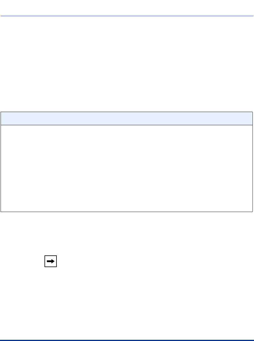
Managing XML Applications
41-001160-03, Rev 00, Release 2.4 F-91
XML SIP Notify
In order for an XML push to bypass the NAT/firewall, the phone supports a
proprietary SIP NOTIFY event (aastra-xml) with or without XML content.
If XML content is provided in the SIP NOTIFY, it is processed directly by the
phone as it is done for an XML PUSH.
If the content is empty in the SIP NOTIFY, the phone automatically triggers a new
pre-configured action uri (action uri xml sip notify).
When the phone receives the SIP NOTIFY, the XML content is processed as any
XML object. In the above example, the phone calls http://10.30.100.39/XMLtests/
SampleTextScreen.xml after reception of the SIP NOTIFY.
Example of a SIP NOTIFY with XML Content
NOTIFY sip:200@10.30.100.103:5060 SIP/2.0
Via: SIP/2.0/UDP 10.30.100.103:5060;branch=z9hG4bK7bbc1fac;rport
From: <sip:201@10.30.100.103:5060>;tag=81be2861f3
To: Jacky200 <sip:200@10.30.100.103:5060>
Contact: <sip:201@10.30.100.103>
Call-ID: 59638f5d95c9d301
CSeq: 4 NOTIFY
Max-Forwards: 70
Event: aastra-xml
Content-Type: application/xml
Content-Length: 115
<AastraIPPhoneExecute><ExecuteItem URI="http://10.30.100.39/XMLtests/
SampleTextScreen.xml"/></AastraIPPhoneExecute>
Note: The phone supports all the current XML objects with all
the existing limitations. For example if an
AastraIPPhoneExecute is used, the embedded uri(s) can not be
HTTPS based.
Draft 1

Managing XML Applications
F-92 41-001160-03, Rev 00, Release 2.4
IP Phone Administrator Guide
When the phone receives the SIP NOTIFY, it will trigger the action uri xml sip
notify parameter,if it has been previously configured using the configuration files
or the Aastra Web UI. If the action uri xml sip notify parameter is not
configured, the phone does not do anything.
On the phone side, a System Administrator can enable or disable this SIP
NOTIFY feature using the configuration files or the phone Web UI.
Also to ensure that the SIP NOTIFY is coming from a trusted source, it is
recommended that you enable the Whitelist feature (Whitelist Proxy parameter)
on the IP phone. If enabled, and the phone receives a SIP NOTIFY from a server
that is NOT on the whitelist, the phone rejects the message.
Reference
For information on enabling/disabling XMLSIP Notify, see Chapter 6, the section,
“XML SIP Notify Events.”
Example of a SIP NOTIFY without XML Content
NOTIFY sip:200@10.30.100.103:5060 SIP/2.0
Via: SIP/2.0/UDP 10.30.100.103:5060;branch=z9hG4bK7bbc1fac;rport
From: <sip:201@10.30.100.103:5060>;tag=81be2861f3
To: Jacky200 <sip:200@10.30.100.103:5060>
Contact: <sip:201@10.30.100.103>
Call-ID: 59638f5d95c9d301
CSeq: 4 NOTIFY
Max-Forwards: 70
Event: aastra-xml
Content-Type: application/xml
Content-Length: 0
Draft 1

41-001160-03, Rev 00, Release 2.4 Warranty-1
Limited Warranty
Limited Warranty
Aastra Telecom warrants this product against defects and malfunctions during a
one (1) year period from the date of original purchase. If there is a defect or
malfunction, Aastra Telecom shall, at its option, and as the exclusive remedy,
either repair or replace the telephone set at no charge, if returned within the
warranty period.
If replacement parts are used in making repairs, these parts may be refurbished, or
may contain refurbished materials. If it is necessary to replace the telephone set, it
may be replaced with a refurbished telephone of the same design and color. If it
should become necessary to repair or replace a defective or malfunctioning
telephone set under this warranty, the provisions of this warranty shall apply to the
repaired or replaced telephone set until the expiration of ninety (90) days from the
date of pick up, or the date of shipment to you, of the repaired or replacement set,
or until the end of the original warranty period, whichever is later. Proof of the
original purchase date is to be provided with all telephone sets returned for
warranty repairs.
Exclusions
Aastra Telecom does not warrant its telephone sets to be compatible with the
equipment of any particular telephone company. This warranty does not extend to
damage to products resulting from improper installation or operation, alteration,
accident, neglect, abuse, misuse, fire or natural causes such as storms or floods,
after the telephone is in your possession.
Aastra Telecom shall not be liable for any incidental or consequential damages,
including, but not limited to, loss, damage or expense directly or indirectly arising
from the customers use of or inability to use this telephone, either separately or in
combination with other equipment. This paragraph, however, shall not apply to
consequential damages for injury to the person in the case of telephones used or
bought for use primarily for personal, family or household purposes.
This warranty sets forth the entire liability and obligations of Aastra Telecom with
respect to breach of warranty, and the warranties set forth or limited herein are the
sole warranties and are in lieu of all other warranties, expressed or implied,
including warranties or fitness for particular purpose and merchantability.
Draft 1

Warranty-2 41-001160-03, Rev 00, Release 2.4
IP Phone Administrator Guide
Limited Warranty
Warranty Repair Services
Should the set fail during the warranty period:
In North America, please call 1-800-574-1611 for further information.
Outside North America, contact your sales representative for return instructions.
You will be responsible for shipping charges, if any. When you return this
telephone for warranty service, you must present proof of purchase.
After Warranty Service
Aastra Telecom offers ongoing repair and support for this product. This service
provides repair or replacement of your Aastra Telecom product, at Aastra
Telecom's option, for a fixed charge. You are responsible for all shipping charges.
For further information and shipping instructions:
In North America, contact our service information number: 1-800-574-1611.
Outside North America, contact your sales representative.
Repairs to this product may be made only by the manufacturer and its authorized
agents, or by others who are legally authorized. This restriction applies during and
after the warranty period. Unauthorized repair will void the warranty.
Draft 1

41-001160-00, Release 2.2 Rev 05 Index-1
Index
802.1x Support 6-31
802.1x local certificate 3-91
802.1x private key 3-91
802.1x root and intermediate certificates 3-90
802.1x trusted certificates 3-91
certificates and private key info 6-31
configuring using the Aastra Web UI 6-39
configuring using the config files 6-33
configuring using the IP Phone UI 6-34
eap-type 3-89
identity 3-89
md5 password 3-90
pc port passthrough enabled 3-90
A
Aastra Web UI
advanced settings description 2-15
basic settings description 2-14
enabling and disabling 2-16
operation description 2-12
status description 2-12
account configuration 3-35
account mode 3-35
custom mode 3-36
phone mode 3-36
ACD
subscription period 5-198
action URIs 3-73, 5-325
action URIs, configuring 5-330
Administration Guide, for IP phone 1-xviii
administrator options 3-1, 4-1
auto call distribution
acd auto available 3-30
acd auto available timer 3-30
subscription period 5-198
Auto Call Distribution (ACD) key 5-148
auto-answer 5-103, A-177
about 5-102
auto-answer, delay before 5-103
B
backlight mode (6755i, 6757i, 6757i CT) A-63
barge in 5-104, A-178
Basic Preferences 3-19
Basic settings
Call Forward Mode 3-23
call waiting 3-20
digit timeout 3-19
display dtmf digits 3-20
DND key mode 3-22
goodbye key cancels incoming call 3-22
incoming call interrupts dialing 3-21
LLDP ELIN 3-23
local dial plan 3-19
MWI Line 3-22
park call (sprecode) (global setting) 3-20
pickup parked call (pickupsprecode global
setting) 3-20
play call waiting tone 3-21
preferred line 3-21
preferred line timeout 3-22
send dial plan terminator 3-19
status scroll delay 3-21
stuttered dial tone 3-21
suppress dtmf playback 3-20
switch focus to ringing line 3-21
UPnP mapping lines 3-22
xml beep support 3-21
beep, for xml applicaton 5-313
beeping, status message G-80
BLA subscription period 5-228
Index
Draft 1

Index-2 41-001160-00, Release 2.2 Rev 05
Index
BLA support for MWI 5-231
blacklist duration 6-22
BLF
configuring 5-173
directed call pickup 5-129
on Asterisk 5-172
on BroadSoft 5-172
overview 5-169
setting 5-169
subscription period 5-176
subscription period, configuring 5-176, 5-198
BLF key 5-147
BLF List,setting 5-170
BLF subscription period 5-176
BLF/List key 5-148
BLF/Xfer key 5-150, 5-178
Bridged Line Appearance (BLA)
about BLA 5-222
configuring 5-223
C
cadence settings, Bellcore A-160
cadences, configuring 5-126
call forward key 5-150
call forwarding 5-249
call waiting 5-67
call waiting tone 5-68
call waiting tones 5-128
callers list
downloading to phone 5-293
enabling/disabling 5-291
overview 5-288
using on phone 5-291
Callers List key 1-25, 1-30
callers list key 1-7, 5-151, 5-159
CancelAction, for XML applciations 5-314
Codecs 4-94
customized preference list of 4-95
conf key 5-152, 5-160
conference key 1-7
enabling/disabling 5-113
mapping as speeddial 5-114
Conference softkey 1-26, 1-30
conferencing, SIP Join feature 5-363
config server
alternate TFTP 3-76
auto resync days 3-83
auto resync max delay 3-83
auto resync mode 3-81
auto resync time 3-82
download path (HTTPS path) 3-80
download port (HTTPS port) 3-80
download protocol 3-75
download server (HTTPS sserver) 3-80
FTP password 3-78
FTP path 3-78
FTP server 3-77
FTP username 3-78
HTTP path 3-79
HTTP port 3-79
HTTP server 3-79
primary TFTP 3-76
select TFTP 3-77
TFTP path 3-76, 3-77
XML application post list 3-83
configuration
file precedence 1-38
methods for performing 2-2
configuration file, description of 1-36
configuration files
installing 1-39
using 2-17
configuration server 4-108
configuring 4-108
configuration server settings 3-75
D
default gateway 3-39
delete key 1-8, 1-22
DHCP 3-38, 4-4
configuring 3-5, 4-5
download preference 4-20
not using 1-33
Option 12 4-11
Option 159 and 160 4-17
Draft 1

41-001160-00, Release 2.2 Rev 05 Index-3
Index
Option 77 User Class 4-14
Options 60, 66, and 43 4-8
using 1-33
using option 43 to customize the phone 4-9
DHCP config option override (configuration
files) 3-42
dhcp user class 3-42
dial plan
configuring 5-57
dial plan, emergency 5-16
dial plan, emergency dial plan and pattern
matching 5-17
dial plans
overview 5-53
Dial softkey 1-26, 1-30
dial tones, stuttered
about 5-70
configuring 5-70, 5-77, 5-85, 5-87, 5-89
DiffServ QoS 4-54
Directed call pickup
configuring 5-132
description of 5-129
directed call pickup
enable/disable 3-29
play ring splash 3-29
prefix setting 3-29
Directed Call Pickup (DCP) key 5-148
Directory key 1-25, 1-30
directory key 1-8, 5-151, 5-159
directory list
download behavior 5-302
downloading procedures 5-306
downloading to server 5-301
limitations for 5-302
overview 5-297
using 5-303
DND
account-based 5-211
configuring 5-203
DND key 5-148
DNS caching 4-23
DNS1 3-39
DNS2 3-40
DSCP 3-51, 4-56
DTMF digits
configuring display of 5-65, 5-68
displaying 5-65
DTMF methods 4-97
DTMF playback, configuring suppression for 5-63
DTMF, out-of-band 4-96
DTMF, suppressing playback 5-63
E
Early-Only parameter in Replaces Header 6-52
emergency dial plan, defining 5-16
empty key 5-153
encryption
methods for 7-2
overview 7-2
procedure for 7-4
Ethernet cable 1-4
expansion module, customizing columns for 5-371,
A-231
expansion module, M670i 1-5
expansion module, M675i 1-5
F
feature keys 5-141
configuring 5-157, A-214
feature keys, configuring 5-162
feature keys, guidelines for programming 5-158
firmware
configuration server requirement for 1-35
description of 1-36
installation considerations 1-33
installation methods 1-33
installing 1-39
firmware update
by restarting the phone 8-5
using the Aastra Web UI 8-2
using the auto-resync feature 8-7
firmware updates 3-84
flash key 5-149, 5-161
Draft 1

Index-4 41-001160-00, Release 2.2 Rev 05
Index
G
General Preferences 3-19
Goodbye Key
canceling incoming call using 5-85
goodbye key 1-7
Group Call Pickup (GCP) key 5-148
GRUU support 6-45
H
handsfree key 1-8
hold key 1-7
hostname 3-40
HTTP and HTTPS support 2-6
HTTP Post G-84
HTTP/HTTPS and Broadsoft CMS 2-8
HTTPS
client functions 2-7
client/server configuration 4-40
security method for A-33, A-34
server functions 2-7
using via Aastra Web UI 2-9
HTTPS certificate expiration 3-49
HTTPS certificate hostname 3-50
HTTPS client method 3-48
HTTPS Server block XML HTTP posts 3-47
HTTPS server redirect 3-47
HTTPS settings 3-47
HTTPS trusted certificates filename 3-50
HTTPS validate certificates 3-49
I
Icom key 5-151
icom key 5-159
incoming call interrupts dialing 5-76
Installation 1-16, 1-18, 1-21
Installation Guide, for IP phone 1-xviii
intercom feature
configuring 5-104
incoming calls 5-103
outgoing calls 5-102
Intercom key 1-30
intercom settings, incoming
allow barge in 3-24
auto-answer 3-24
microphone mute 3-24
play warning tone 3-24
intercom settings, outgoing
line 3-25
prefix code 3-25
type 3-25
intercom warning tone A-178
IP phone UI 2-2
K
key descriptions 1-11
key list in Web UI, customizing 5-164
key mapping
map conf key to 3-26
map redial key to 3-26
key mapping, enable/disable Redial, Xfer, Conf
Keys 5-113
key press simulation G-60
key press simulation, XML URI 5-355
key redirection (redial, conf, xfer, icom,
voicemail) 5-352
L
LAN Port 3-40
Language
language 1 thru 4 3-34
language
overview 5-34
specifying on IP phone 5-37
WebPage Language 3-33, 3-34
language pack settings A-164
language settings A-162
language, input 5-41
keypad alpabet tables 5-41
specifying in XML applications 5-47
Draft 1

41-001160-00, Release 2.2 Rev 05 Index-5
Index
specifying using the Aastra Web UI 5-46
specifying using the configuration files 5-44
specifying using the IP Phone UI 5-44
last call return (lcr)
configuring 5-245
how it works 5-245
lcr key 5-150
line key 5-147, 5-159
line settings 3-71
line/call appearance keys 1-8
LLDP 3-43
lldp packet interval 3-43
LLDP-MED and ELIN 5-97
local dial plan
dial plan terminator 5-55
secondary dial tone 5-56
lockIn, for xml applications 5-314
locking keys, on the IP phone 5-49
locking keys, procedures 5-50
locking softkeys and programmable keys A-226,
A-231
locking/unlocking the phone 5-10
M
microphone mute A-177
missed calls indicator
accessing and clearing 5-296
enabling/disabling 5-295
overview 5-295
Model 6751i 1-15
Model 6753i 1-20
Model 6755i 1-23
Model 6757i 1-27
Model 6757i Cordless Handset 1-31
Model 6757i CT 1-27
Model 9143i 1-6
Model 9480i 1-10
Model 9480i CT 1-10
Model 9480i CT Cordless Handset 1-13
N
NAP SIP port 3-44
NAT
configuring 4-32
configuring NAT address and port 4-35
Nortel Networks 4-32
overview 4-30
router configuration 4-31
NAT IP 3-44
NAT RTP port 3-45
navigation keys 1-7
network configuration 4-4
network parameters A-8
network settings, advanced 3-41, 3-47, 4-30
DHCP download options 3-42
DHCP user class 3-42
HTTPS block XML HTTP Posts 3-47
HTTPS certificate expiration 3-49
HTTPS certificate hostname 3-50
HTTPS Client Method 3-48
HTTPS redirect 3-47
HTTPS trusted certificates filename 3-50
LLDP packet interval 3-43
LLDP support 3-43
NAT IP 3-44
NAT RTP port 3-45
NAT SIP Port 3-44
Nortel NAT 3-45
Nortel NAT timer 3-45
NTP time servers 3-45, 3-46
Time Servers 1 thru 3 3-46
UPnP 3-44
upnp gateway 3-44
network settings, basic 3-38, 4-4
DHCP 3-38
Ethernet (PC Port and LAN Port) 3-40
gateway 3-39
hostname 3-40
IP Address 3-38
primary DNS 3-39
secondary DNS 3-40
subnet mask 3-39
network settings, configuring 4-24
none key 5-147, 5-159
Draft 1

Index-6 41-001160-00, Release 2.2 Rev 05
Index
Nortel NAT timer 3-45
Nortel NAT traversal enabled 3-45
Nortel Proxy 4-31
NTP time servers 3-46
O
operational features 5-5
operational features, advanced 6-3
configuring line number 6-5
configuring MAC address 6-5
configuring message sequence for blind
transfer 6-7
options
via Aastra Web UI 3-6
via Configuration Files 3-8
via IP Phone UI 3-3
options key 1-8
Options key redirection 5-353
options menu, simplified A-7
out of sequence errors, ignoring 6-51
P
paging
configuring group RTP settings 5-109
group RTP setting description 5-107
Paging key 5-153
paging RTP
paging listen addresses 3-26
parameters
6755i, 6757i, 6757i CT softkeys A-193
802.1x support settings A-109
Aastra Web UI A-17
acd auto-available timer A-186
ACD subscription period A-100
Action URIs A-135
advanced SIP A-92
as-feature-event subscription A-104
audio transmit and receive adjustment
settings A-180
auto-answer settings A-175
backlight mode (6755i, 6757i, 6757i CT) A-63
BLA support for MWI A-87
blacklist duration A-236
BLF list URI A-230
BLF subscription period A-99
blind transfer setting A-233
boot sequence recover mode A-234
call forward key mode A-127
call forward settings A-126
call waiting settings A-152
Callers List settings A-124
centralized conferencing A-88
configuration encryption setting A-243
configuration server A-18
custom time zone and dst settings A-54
customized callers list and services keys A-125
customzing Aastra Web UI Key List A-223
DHCP option settings A-13
dial plan A-65
directed call pickup A-184
directory settings A-123
DND key mode A-154
dns query setting A-242
DSCP A-44
DTMF digits A-174
emergency dial plan A-16
expansion module keys A-216
global ring tone settings A-143
global SIP A-67
goodbye key cancels incoming call A-150
group paging RTP settings A-179
GRUU Support A-241
handset feature keys A-214
HTTP/HTTPS authentication with Broadsoft
CMS A-91
HTTPS client and server settings A-33
HTTPS server certificate validation A-35
incoming call interrupts dialing A-146
incoming intercom A-177
Intercom settings A-175
language A-162
language pack A-164
live dialpad A-64
LLDP ELIN A-129
local SIP TLS port A-32
local SIP UDP/TCP port A-32
locking SAVE and DELTE keys (6753i) A-229
locking softkeys and programmable keys A-226
MAC Address/Line Number A-93
mapping key A-189
Draft 1

41-001160-00, Release 2.2 Rev 05 Index-7
Index
message waiting indicator A-153
missed call summary subscription period A-102
missed call summary subscription, global A-101
missed call summary subscription, per-line A-103
Missed Calls Indicator settings A-131
NAT A-29
out of order SIP requests A-243
outgoing intercom A-175
park and pickup global settings A-187
password A-15
per-line ring tone settings A-145
per-line SIP A-76
polling action URIs A-142
preferred line A-149
preferred line timeout A-149
priority alert settings A-155
programmable keys (6753i, 6755i) A-202
rport A-31
RTP, Codec, DTMF global settings A-114
silence suppression settings A-117
single call restriction setting A-235
SIP join feature A-90
SIP registration retry timer A-98
softkeys, programmable keys, feature keys A-192
stuttered dial tone setting A-151
Suppress DTMF Playback A-173
switch focus to ringing line A-148
symmetric UDP signaling A-240
time and date A-45
time server A-52
top softkeys A-207
ToS A-44
Transport Layer Security (TLS) A-105
updating caller ID A-233
UPnP A-37
user-agent setting A-241
VLAN A-38
voicemail A-122
whitelist proxy A-236
XML key redirection (redial, xfer, conf, icom,
voicemail) A-237
XML override for a locked phone A-240
XML settings A-132
XML SIP notify A-141
parameters, list of configurable A-7
time server settings A-52
parameters, setting in configuration files A-6
park key 5-150, 5-160
park/pickup
about parked/pickup calls 5-59, 5-234
configuring a static configuration 5-61
configuring programmable configuration using
config files 5-236
configuring programmable configuration using Web
UI 5-238
programmable configuration of 5-234
static configuration of 5-59
using on the IP phone 5-243
pass-thru port 3-40
password, resetting user’s 5-7
passwords
for a user 5-5
for an administrator 5-9
PC Port 3-40
phone lock key 5-152
Phone Status
Firmware Version 3-10
IP&MAC Address 3-10
LAN Port 3-10
PC Port 3-10
phone status settings 3-9
pickup key 5-150, 5-160
play warning tone 5-103
PoE 1-4
preferred line 5-81
preferred line timeout 5-81
priority alerting
about 5-122
configuring 5-126
priority alerting settings
auto call distribution 3-28
community 1 thru 4 3-28
emergency 3-28
enabling 3-27
external 3-28
group 3-27
internal 3-28
priority 3-28
programmable keys 5-141
configuring 5-154
Draft 1

Index-8 41-001160-00, Release 2.2 Rev 05
Index
public key 5-161
Q
QoS 4-54
R
Reason Header field in SIP message 6-52
redial key 1-7
enabling/disabling 5-113
mapping as speeddial 5-114
repair 0-2
requirements, IP phone 1-34
restarting IP phone 3-13
ring tone
global ring tone 3-27
patterns used for 5-123
per-line ring tone 3-27
tone set setting 3-27
ring tone sets 5-119
configuring 5-120
ring tones 5-117
configuring 5-120
ring tone 3-27
tone set 3-27
Rport 3-45
rport, configuring 4-65
RTP
basic codecs for 4-94
configuring 4-93, 4-99
customized codec preference list 4-95
dtmf method 4-97
encryption method (SRTP) 4-97
out-of-band DTMF 4-96
RTP port 4-94
silence suppression 4-98
rtp encryption 4-97
RTP port 4-94
RTP settings 3-68, 3-70
S
SAVE and DELETE keys, locking (6753i) A-229
save key 1-8, 1-22
SBG and ALG proxy 4-31
screen timeout, for XML 5-313
scroll delay 5-313
scrolling, status message G-80
Services key 1-25, 1-30
services key 5-152
silence suppression 4-98
SIP
advanced settings 4-84
configuring 4-76
overview of 4-70
parameter precedence 4-73
SIP settings
autodial number 3-70
autodial timeout 3-70
autodial, use global settings 3-70
RTP port 3-68
SIP settings, advanced 3-61
acd subscription period 3-66
as-feature-event subscription 3-62
as-feature-event subscription period 3-62
bla subscription period 3-66
blacklist duration 3-66
BLF subscription period 3-66
explicit mwi subscription 3-61
explicit mwi subscription period 3-61
local SIP UDP/TCP Port 3-64, 3-65
missed call summary subscription 3-61
missed call summary subscription period 3-62
registration failed retry timer 3-65
registration renewal timer 3-65
registration timeout retry timer 3-65
send line number in REGISTER message 3-63
send MAC address in REGISTER message 3-62
session timer 3-63
timer 1 and timer 2 3-63
transaction timer 3-63
transport protocol 3-64
whitelist proxy 3-67
XML SIP Notify 3-67
SIP settings, basic 3-56
auth name 3-57
BLA number 3-57
caller ID 3-56
Draft 1

41-001160-00, Release 2.2 Rev 05 Index-9
Index
display name 3-56
line mode 3-57
password 3-57
phone number 3-56
screen name 3-56
screen name 2 3-56
user name 3-56
SIP settings, network
backup proxy port 3-58
backup proxy server 3-58
backup registrar port 3-60
backup registrar server 3-60
outbound proxy port 3-59
outbound proxy server 3-59
proxy port 3-58
proxy server 3-58
registrar port 3-59
registrar server 3-59
registration period 3-60
SIP Settings, RTP
Basic Codecs 3-68
customized Codec preference list 3-69
DTMF method 3-69
Force RFC2833 Out of Band DTMF 3-68
RTP encryption 3-69
RTP port 3-68
silence suppression 3-69
Softkey settings A-192
softkeys 5-141
configuring 5-154
Softkeys and Programmable Keys
locking 5-50, 5-371
softkeys and programmable keys
locking A-226
softkeys, state-based 5-142
speeddial key 5-147
speeddial keys
enabling/disabling ability to add and edit 5-168
prefixes for 5-167
Speeddial/Conf key 5-151, 5-184
Speeddial/Xfer key 5-151, 5-178
sprecode key 5-150
SRV lookup, configuring 4-75
status message beep
configuring in configuration files and Web
UI 5-315
status message scrolling G-80
configuring in configuration files and Web
UI 5-316
subnet mask 3-39
switch focus to ringing line 5-79
T
time and date
date format 3-31
NTP time servers 3-31
time format 3-31
Time Server 1 3-32
Time Server 2 3-32
Time Server 3 3-32
time and date, configuring 5-23
time servers, configuring 4-67
time zone and dst settings, custom 5-20, A-54
absolute A-55
relative time A-58
TLS (Transport Layer Security) 6-26
configuring using the Aastra Web UI 6-29
configuring using the config files 6-28
SIP asserted identify (Sylantro Servers) 6-27
TLS support
sip persistent tls 3-86
sip transport protocol 3-85
sips local certificate 3-87
sips private key 3-88
sips root and intermediate certificates 3-87
sips trusted certificates 3-88
ToS 4-54
ToS, DSCP 3-51
transfer key 1-7
Transfer softkey 1-26, 1-30
troubleshooting 9-3
error messages 9-15
log settings 9-3
log settings for A-244
module/debug level settings 9-4
solutions to common problems 9-19
support information 9-7
Draft 1

Index-10 41-001160-00, Release 2.2 Rev 05
Index
watchdog feature 9-12
WatchDog tasks for A-247
Tx/Rx adjustments
about 5-357
configuring 5-358
type of service
RTCP 3-51
RTP 3-51
SIP 3-51
U
upgrading, firmware 8-2
UPnP
configuring 4-51, A-37
description of 4-50
upnp gateway 3-44
upnp manager 3-44
User Guide, for IP phone 1-xviii
usernames
administrator 2-11, 3-6, 4-3
configuring for FTP server 4-114
configuring for SIP authentication 4-78
for FTP A-22
for SIP authentication 4-71, 4-72, A-68, A-77
global BLA 5-223
per-line BLA 5-224
user 2-11
V
VLAN 3-52
configuring 4-54
DSCP Range 4-56
global priority non-IP packet 3-52
global VLAN enable 3-52
LAN Port SIP, RTP, RTCP Priority 3-53
LAN Port VLAN ID 3-52
PC Port priority 3-54
PC Port VLAN ID 3-54
priority mapping 4-56
voicemail
configuring 5-308
overview 5-308
using 5-310
volume key 1-7
W
warranty 0-1
warranty exclusions 0-1
WebApps key 5-149
whilte list proxy 6-24
X
xfer key 5-152, 5-160
Xfer key, enabling/disabling 5-113
XML
AastraIPPhoneConfiguration object G-64
AastraIPPhoneDirectory object G-39
AastraIPPhoneFormattedTextScreen object G-19
AastraIPPhoneInputScreen object G-23
AastraIPPhoneStatus object G-41
AastraIPPhoneTextMenu object G-6
AastraIPPhoneTextScreen object G-14
action URIs 5-325
Answer and Ignore softkeys G-17
attributes and objects for XML G-80
configuring on IP phone 5-317
configuring SIP Notify for empty message 5-344
creating custom softkeys G-5
creating customized services 5-311
customized services 5-311
dialpad passthrough G-22
disconnected action URI 5-336
Drop, Conf, Xfer softkeys G-30
enabling/disabling SIP Notify 5-341
HTTP Post G-84
Image objects G-70
key redirection 5-352
managing applications for G-90
multiple input fields G-34
off-hook interaction with XML applications 5-355
Options key redirection (Services key on
6751i) 5-353
override for a locked phone 5-356
polling action URIs 5-334
procedure for configuring 5-318
push from the server 5-316
push requests 5-318
Draft 1

41-001160-00, Release 2.2 Rev 05 Index-11
Index
scroll delay for status messages 5-316
SetType attribute used with object G-66
SIP Notify events 5-339
softkey URIs 5-345
special character softkeys G-28
status message beep 5-315
text wrapping G-12
time and date formats G-31
turning off automatic numbering G-8
URI for key press simulation G-60
using bullets in menu items G-10
using customized services 5-323
using execute commands G-43
WebApps key 5-351
XML schema file G-87
xml beep support 5-72, 5-74
XML Get timeout 5-313
XML key 5-149
XML SIP Notify G-91
Draft 1

Index-12 41-001160-00, Release 2.2 Rev 05
Index
Draft 1

Draft 1

SIP IP Phone Administrator Guide
Models 9143i, 9480i, 9480i CT, and 675xi Series
© 2008 Aastra Telecom Inc.
If you’ve read this owner’s manual and consulted the Troubleshooting section and
still have problems, please visit our website at www.aastratelecom.com or call 1-800-574-1611
for technical assistance.
41-001160-03, Rev 00
Release 2.4
October 2008
Draft 1
