Abbott Medical Optics SIGACPS Advanced Control Pedal Slave User Manual Whitestar OM
Abbott Medical Optics Advanced Control Pedal Slave Whitestar OM
Users Manual
Page 1 of 204
MANUAL SPECIFICATION
DOCUMENT NO: Z370147
REVISION: C
TITLE: WHITESTAR SIGNATURETM OWNER’S AND OPERATOR’S MANUAL (ENGLISH)
SOFTWARE VERSION 1.003, CE
SPECIFICATIONS:
1. BINDER:
8 ½” x 11 x 1 ½” White vinyl with clear-view insert pockets or equivalent, 3 rings.
2. TEXT:
2.1 DIMENSIONS: 8 1/2“ x 11” three rings, white laser paper
2.2 TYPE OF PAPER: 20lb. Bond, White, 3 ring punched
2.3 INK/COLOR: Black on white paper. Printing to be clear and legible with no
ink smears.
2.4 TYPE OF COPY: Single Copy, print 2 sides. Each chapter must start on a right-
facing page.
3. COVER & SPINE: Z330075 for Label Specifications.
4. TAB PAGES: Z330077 for Label Specifications.
5. ASSEMBLY / PACKAGING: Index tabs in the appropriate sections of the manual.
Shrink-wrap assembled binder with copy of first page of document (cover page)
between shrink and outside of binder. Manual identify from cover page (version, part
number, etc.) must be facing out and visible for warehouse identification.
6. LANGUAGES: English
7. POINTS OF USE: AMO, Corporate, Santa Ana, Milpitas
CHANGE SUMMARY
REVISION DESCRIPTION OF CHANGE
A Create new manual for WHITESTAR SIGNATURETM Owner’s manual
Software Version 1.03. For clinical use only.
B Production manual for the 1.03 software version – updates for Venturi in all
surgical modes and the Dual Linear Foot Pedal (Advanced Control Pedal)
C Update to Reflux Description, Distributor address, New terms in glossary –
New screens for Passive Reflux.
WHITESTAR SIGNATURE™
OWNER’S AND
OPERATOR’S MANUAL
Manufactured By:
Advanced Medical Optics, Inc.
1700 E. St. Andrew Place
Santa Ana, CA 92705
USA
1-800-449-3060
www.amo-inc.com
For Order Placement
of Surgical Products
(IOLs and Phaco Supplies)
Call 1-877-AMO-4LIFE (USA)
1-877-266-4543
For Phaco Returns or Technical
Service
Call 1-877-AMO-4LIFE (USA)
1-877-266-4543
All returns must be accompanied by a
RGA#
(Returned Goods Authorization)
EC REP
AMO Ireland
Block B
Liffey Valley Office Campus
Quarryvale Co., Dublin Ireland
Rx Only – Z370147 Rev C 1108
© 2008 Advanced Medical Optics, Inc.
Trademarks
AMO, the AMO ADVANCED MEDICAL OPTICS logo, and WHITESTAR are registered trademarks and
ELLIPS, the ELLIPS logo, FUSION, the FUSION logo, LAMINAR, PHACOFIT, OCCLUSION MODE,
and WHITESTAR SIGNATURE are trademarks of Advanced Medical Optics, Inc.
DUET and SOLO are trademarks of Micro-Surgical Technology, Inc.
Bluetooth is a registered trademark of Bluetooth SIG, Inc.
All brand names and products and company names mentioned in this document are the trade name,
service mark, or registered trademarks of their respective owners.
Compliance
In accordance with:
• IEC/EN 60601-1

Table of Contents
WHITESTAR SIGNATURE™ System Rx Only – Z370147 Rev. C 1108 i
TABLE OF CONTENTS
Introduction . . . . . . . . . . . . . . . . . . . . . . . . . . . . . . . . . . . . . . . . . . . . . . . . . . . . . . . . . . . . 1-1
About this Manual . . . . . . . . . . . . . . . . . . . . . . . . . . . . . . . . . . . . . . . . . . . . . . . . . . . . . . . . 1-2
About Phacoemulsification. . . . . . . . . . . . . . . . . . . . . . . . . . . . . . . . . . . . . . . . . . . . . . . . . . 1-2
Intended Use . . . . . . . . . . . . . . . . . . . . . . . . . . . . . . . . . . . . . . . . . . . . . . . . . . . . . . . . . . . . . 1-2
WHITESTAR SIGNATURE™ System Description & Features. . . . . . . . . . . . . . . . . . . . . 1-2
WHITESTAR® Technology . . . . . . . . . . . . . . . . . . . . . . . . . . . . . . . . . . . . . . . . . . . . . . . . 1-3
FUSION™ Fluidics System . . . . . . . . . . . . . . . . . . . . . . . . . . . . . . . . . . . . . . . . . . . . . . . . . 1-4
Accessories . . . . . . . . . . . . . . . . . . . . . . . . . . . . . . . . . . . . . . . . . . . . . . . . . . . . . . . . . . . . . . 1-4
WHITESTAR SIGNATURE™ System Console. . . . . . . . . . . . . . . . . . . . . . . . . . . . . . . . . 1-5
WHITESTAR SIGNATURE™ System Operating Modes . . . . . . . . . . . . . . . . . . . . . . . . . 1-6
System Components . . . . . . . . . . . . . . . . . . . . . . . . . . . . . . . . . . . . . . . . . . . . . . . . . . . . . . 2-1
Receipt and Inspection Instructions . . . . . . . . . . . . . . . . . . . . . . . . . . . . . . . . . . . . . . . . . . . 2-2
WHITESTAR SIGNATURE™ System Components . . . . . . . . . . . . . . . . . . . . . . . . . . . . . 2-2
WHITESTAR SIGNATURE™ System with FUSION™ Tubing Pack . . . . . . . . . . . . . . . 2-4
System Setup. . . . . . . . . . . . . . . . . . . . . . . . . . . . . . . . . . . . . . . . . . . . . . . . . . . . . . . . . . . . 3-1
Safety Precautions. . . . . . . . . . . . . . . . . . . . . . . . . . . . . . . . . . . . . . . . . . . . . . . . . . . . . . . . . 3-2
Warnings. . . . . . . . . . . . . . . . . . . . . . . . . . . . . . . . . . . . . . . . . . . . . . . . . . . . . . . . . . . . . . . . 3-5
Symbol Definitions. . . . . . . . . . . . . . . . . . . . . . . . . . . . . . . . . . . . . . . . . . . . . . . . . . . . . . . . 3-9
System Disposal . . . . . . . . . . . . . . . . . . . . . . . . . . . . . . . . . . . . . . . . . . . . . . . . . . . . . . . . . 3-12
Setup Sequence – Anterior Segment Surgery. . . . . . . . . . . . . . . . . . . . . . . . . . . . . . . . . . . 3-15
Footpedal . . . . . . . . . . . . . . . . . . . . . . . . . . . . . . . . . . . . . . . . . . . . . . . . . . . . . . . . . . . . . . 3-22
Programmable IV Pole . . . . . . . . . . . . . . . . . . . . . . . . . . . . . . . . . . . . . . . . . . . . . . . . . . . . 3-25
Wireless Remote Control (Optional) . . . . . . . . . . . . . . . . . . . . . . . . . . . . . . . . . . . . . . . . . 3-26
Surgical Media Center (SMC) (Optional) . . . . . . . . . . . . . . . . . . . . . . . . . . . . . . . . . . . . . 3-27
Shutdown Sequence – Anterior Segment Surgery . . . . . . . . . . . . . . . . . . . . . . . . . . . . . . . 3-29
Equipment Operation . . . . . . . . . . . . . . . . . . . . . . . . . . . . . . . . . . . . . . . . . . . . . . . . . . . . 4-1
Display Screens and Controls. . . . . . . . . . . . . . . . . . . . . . . . . . . . . . . . . . . . . . . . . . . . . . . . 4-2
Language Selection. . . . . . . . . . . . . . . . . . . . . . . . . . . . . . . . . . . . . . . . . . . . . . . . . . . . . . . . 4-3
Startup. . . . . . . . . . . . . . . . . . . . . . . . . . . . . . . . . . . . . . . . . . . . . . . . . . . . . . . . . . . . . . . . . . 4-4
Select Program and Install the FUSION™ Tubing Cassette . . . . . . . . . . . . . . . . . . . . . . . . 4-6
Prime/Tune . . . . . . . . . . . . . . . . . . . . . . . . . . . . . . . . . . . . . . . . . . . . . . . . . . . . . . . . . . . . . . 4-7
Verify Irrigation/Aspiration Balance . . . . . . . . . . . . . . . . . . . . . . . . . . . . . . . . . . . . . . . . . 4-10
Priming for Vitrectomy. . . . . . . . . . . . . . . . . . . . . . . . . . . . . . . . . . . . . . . . . . . . . . . . . . . . 4-11
Selecting and Changing Mode Parameters . . . . . . . . . . . . . . . . . . . . . . . . . . . . . . . . . . . . . 4-12

Table of Contents
WHITESTAR SIGNATURE™ System Rx Only – Z370147 Rev. C 1108 ii
Anterior Segment Surgery Operating Modes . . . . . . . . . . . . . . . . . . . . . . . . . . . . . . . . . 5-1
Operating Mode Descriptions. . . . . . . . . . . . . . . . . . . . . . . . . . . . . . . . . . . . . . . . . . . . . . . . 5-2
Fusion™ Fluidics Phaco. . . . . . . . . . . . . . . . . . . . . . . . . . . . . . . . . . . . . . . . . . . . . . . . . . . 5-15
Programming the Modes and Settings . . . . . . . . . . . . . . . . . . . . . . . . . . . . . . . . . . . . . . . . 5-21
Anterior Segment – Recommended Settings . . . . . . . . . . . . . . . . . . . . . . . . . . . . . . . . . . . 5-37
OCCLUSION MODE™ Phaco Settings . . . . . . . . . . . . . . . . . . . . . . . . . . . . . . . . . . . . . . 5-41
Passive Reflux. . . . . . . . . . . . . . . . . . . . . . . . . . . . . . . . . . . . . . . . . . . . . . . . . . . . . . . . . . . 5-48
Ellips™ Technology. . . . . . . . . . . . . . . . . . . . . . . . . . . . . . . . . . . . . . . . . . . . . . . . . . . . . . 5-48
Surgeon Programs . . . . . . . . . . . . . . . . . . . . . . . . . . . . . . . . . . . . . . . . . . . . . . . . . . . . . . . 6-1
Select Surgeon/Program . . . . . . . . . . . . . . . . . . . . . . . . . . . . . . . . . . . . . . . . . . . . . . . . . . . . 6-2
Add a New Surgeon . . . . . . . . . . . . . . . . . . . . . . . . . . . . . . . . . . . . . . . . . . . . . . . . . . . . . . . 6-3
Edit a Surgeon. . . . . . . . . . . . . . . . . . . . . . . . . . . . . . . . . . . . . . . . . . . . . . . . . . . . . . . . . . . . 6-5
Select a Preferred Program . . . . . . . . . . . . . . . . . . . . . . . . . . . . . . . . . . . . . . . . . . . . . . . . . . 6-6
Create a New Program . . . . . . . . . . . . . . . . . . . . . . . . . . . . . . . . . . . . . . . . . . . . . . . . . . . . . 6-8
Edit a Surgeon Program . . . . . . . . . . . . . . . . . . . . . . . . . . . . . . . . . . . . . . . . . . . . . . . . . . . . 6-9
Copy a Surgeon Program . . . . . . . . . . . . . . . . . . . . . . . . . . . . . . . . . . . . . . . . . . . . . . . . . . 6-10
Delete a Surgeon. . . . . . . . . . . . . . . . . . . . . . . . . . . . . . . . . . . . . . . . . . . . . . . . . . . . . . . . . 6-11
Delete a Program . . . . . . . . . . . . . . . . . . . . . . . . . . . . . . . . . . . . . . . . . . . . . . . . . . . . . . . . 6-12
Delete a Database . . . . . . . . . . . . . . . . . . . . . . . . . . . . . . . . . . . . . . . . . . . . . . . . . . . . . . . . 6-13
Lock a Program. . . . . . . . . . . . . . . . . . . . . . . . . . . . . . . . . . . . . . . . . . . . . . . . . . . . . . . . . . 6-13
Program – Assign Order . . . . . . . . . . . . . . . . . . . . . . . . . . . . . . . . . . . . . . . . . . . . . . . . . . . 6-14
Diagnostics . . . . . . . . . . . . . . . . . . . . . . . . . . . . . . . . . . . . . . . . . . . . . . . . . . . . . . . . . . . . . 7-1
Diagnostics . . . . . . . . . . . . . . . . . . . . . . . . . . . . . . . . . . . . . . . . . . . . . . . . . . . . . . . . . . . . . . 7-2
Wireless Footpedal Setup . . . . . . . . . . . . . . . . . . . . . . . . . . . . . . . . . . . . . . . . . . . . . . . . . . . 7-3
Wireless Foot Pedal Calibration . . . . . . . . . . . . . . . . . . . . . . . . . . . . . . . . . . . . . . . . . . . . . . 7-5
Wireless Remote Control Setup . . . . . . . . . . . . . . . . . . . . . . . . . . . . . . . . . . . . . . . . . . . . . . 7-6
Calibrate Touch Screen . . . . . . . . . . . . . . . . . . . . . . . . . . . . . . . . . . . . . . . . . . . . . . . . . . . . 7-7
Check-out Precautions. . . . . . . . . . . . . . . . . . . . . . . . . . . . . . . . . . . . . . . . . . . . . . . . . . . . 8-1
System Check-out. . . . . . . . . . . . . . . . . . . . . . . . . . . . . . . . . . . . . . . . . . . . . . . . . . . . . . . . . 8-2
Care and Cleaning . . . . . . . . . . . . . . . . . . . . . . . . . . . . . . . . . . . . . . . . . . . . . . . . . . . . . . . 9-1
Cleaning Procedures . . . . . . . . . . . . . . . . . . . . . . . . . . . . . . . . . . . . . . . . . . . . . . . . . . . . . . . 9-2
Sterilization Procedures . . . . . . . . . . . . . . . . . . . . . . . . . . . . . . . . . . . . . . . . . . . . . . . . . . . . 9-4
WHITESTAR SIGNATURE™ System Cleaning and Care . . . . . . . . . . . . . . . . . . . . . . . . 9-5

Table of Contents
WHITESTAR SIGNATURE™ System Rx Only – Z370147 Rev. C 1108 iii
Error Messages Troubleshooting and Diagnostics . . . . . . . . . . . . . . . . . . . . . . . . . . . . 10-1
Error Message Display . . . . . . . . . . . . . . . . . . . . . . . . . . . . . . . . . . . . . . . . . . . . . . . . . . . . 10-2
Fuse Replacement Procedure . . . . . . . . . . . . . . . . . . . . . . . . . . . . . . . . . . . . . . . . . . . . . . . 10-2
Wireless Foot Pedal Battery Replacement Procedure . . . . . . . . . . . . . . . . . . . . . . . . . . . . 10-3
Most Common User-Correctable Problems . . . . . . . . . . . . . . . . . . . . . . . . . . . . . . . . . . . . 10-5
Status, Warning and Error Messages . . . . . . . . . . . . . . . . . . . . . . . . . . . . . . . . . . . . . . . . . 10-5
System Operation (Error) Messages. . . . . . . . . . . . . . . . . . . . . . . . . . . . . . . . . . . . . . . . . . 10-5
Troubleshooting . . . . . . . . . . . . . . . . . . . . . . . . . . . . . . . . . . . . . . . . . . . . . . . . . . . . . . . . 10-15
Warranty and Maintenance . . . . . . . . . . . . . . . . . . . . . . . . . . . . . . . . . . . . . . . . . . . . . . 11-1
Warranty Statement . . . . . . . . . . . . . . . . . . . . . . . . . . . . . . . . . . . . . . . . . . . . . . . . . . . . . . 11-2
Specifications . . . . . . . . . . . . . . . . . . . . . . . . . . . . . . . . . . . . . . . . . . . . . . . . . . . . . . . . . . 12-1
Physical Specifications . . . . . . . . . . . . . . . . . . . . . . . . . . . . . . . . . . . . . . . . . . . . . . . . . . . . 12-2
Environmental Specifications. . . . . . . . . . . . . . . . . . . . . . . . . . . . . . . . . . . . . . . . . . . . . . . 12-3
Electrical Specifications . . . . . . . . . . . . . . . . . . . . . . . . . . . . . . . . . . . . . . . . . . . . . . . . . . . 12-3
Diathermy Specifications . . . . . . . . . . . . . . . . . . . . . . . . . . . . . . . . . . . . . . . . . . . . . . . . . . 12-3
Irrigation and Aspiration Specifications. . . . . . . . . . . . . . . . . . . . . . . . . . . . . . . . . . . . . . . 12-3
Phacoemulsification Specifications . . . . . . . . . . . . . . . . . . . . . . . . . . . . . . . . . . . . . . . . . . 12-4
Vitrectomy Specifications. . . . . . . . . . . . . . . . . . . . . . . . . . . . . . . . . . . . . . . . . . . . . . . . . . 12-4
Diathermy Power Graphs . . . . . . . . . . . . . . . . . . . . . . . . . . . . . . . . . . . . . . . . . . . . . . . . . . 12-5
Diathermy Power versus Load Impedance . . . . . . . . . . . . . . . . . . . . . . . . . . . . . . . . . . . . 12-10
Phaco Power Graphs. . . . . . . . . . . . . . . . . . . . . . . . . . . . . . . . . . . . . . . . . . . . . . . . . . . . . 12-13
Accessories and Parts Reordering . . . . . . . . . . . . . . . . . . . . . . . . . . . . . . . . . . . . . . . . . 13-1
List of Accessories with Part Numbers. . . . . . . . . . . . . . . . . . . . . . . . . . . . . . . . . . . . . . . . 13-2
Glossary. . . . . . . . . . . . . . . . . . . . . . . . . . . . . . . . . . . . . . . . . . . . . . . . . . . . . . . . . . Glossary-1
Index . . . . . . . . . . . . . . . . . . . . . . . . . . . . . . . . . . . . . . . . . . . . . . . . . . . . . . . . . . . . . . .Index-1

WHITESTAR SIGNATURE™ System Rx Only – Z370147 Rev. C 1108 1-1
About this Manual
About Phacoemulsification
Intended Use
WHITESTAR SIGNATURE™ System Description & Features
WHITESTAR® Technology
FUSION™ Fluidics System
Accessories
WHITESTAR SIGNATURE™ System Console
WHITESTAR SIGNATURE™ System Operating Modes
1INTRODUCTION

1 • Introduction
WHITESTAR SIGNATURE™ System Rx Only – Z370147 Rev. C 1108 1-2
About this Manual This manual includes information about the WHITESTAR SIGNATURE™
System which is designed for anterior segment (phacoemulsification) surgical
procedures.
This manual includes information regarding optional System enhancements. The
availability of these features in your System configuration and availability in your
area can be confirmed by your AMO representative.
About
Phacoemulsification Over thirty years ago, Dr. Charles Kelman conceived and developed
phacoemulsification, a method of cataract removal using ultrasonic emulsification
and aspiration of the cataractous lens through a small incision. Phacoemulsification
is advantageous for both patient and surgeon:
• Greater intraoperative control.
• The smaller incision requires fewer or no sutures, poses less risk of infection and
induced astigmatism, and gives better long-term and short-term predictability of
vision.
• Patients are able to resume normal activity much sooner and with fewer
restrictions than with traditional cataract extraction surgeries.
Advanced Medical Optics, Inc. (AMO) supports phacoemulsification with
sophisticated instrumentation that optimizes the benefits of this surgical procedure.
Intended Use The WHITESTAR SIGNATURE™ System is a modular ophthalmic microsurgical
system that facilitates anterior segment (cataract) surgery. The modular design
allows the users to configure the system to meet their surgical requirements.
This HIGH FREQUENCY (HF) SURGICAL EQUIPMENT is specified for use
without a NEUTRAL ELECTRODE.
WHITESTAR
SIGNATURE™
System Description
& Features
The WHITESTAR SIGNATURE™ System is a multi-functional tool for use in
anterior segment surgery and procedures. The WHITESTAR SIGNATURE™
System represents the latest generation of AMO® phacoemulsification technology.
Safety, ease-of-use, and reliability are designed and manufactured into every
WHITESTAR SIGNATURE™ System. The WHITESTAR SIGNATURE™
System meets applicable United States and International safety requirements for
this type of device.
The WHITESTAR SIGNATURE™ System contains a number of features based on
extensive research and clinical trials with highly-trained and noted
ophthalmologists who are experienced phacoemulsification surgeons.

1 • Introduction
WHITESTAR SIGNATURE™ System Rx Only – Z370147 Rev. C 1108 1-3
WHITESTAR®
Technology The WHITESTAR® Technology represents the many enhancements to the power
modulation for the WHITESTAR SIGNATURE™ System. The WHITESTAR®
Technology enhancement was the first to deliver finely modulated pulses of
energy, interrupted by extremely brief cooling periods. This allows the
WHITESTAR SIGNATURE™ System to achieve full ultrasound cutting
efficiency and magnetic followability, while introducing less energy into the eye.
Ultrasound time is minimized or eliminated to reduce the risk of thermal damage.
WHITESTAR® ICE Technology
The WHITESTAR® ICE Technology was the next micro-pulse advance in
phacoemulsification technology, which combined modulated ultrasonic power
(pulse shaping) with vacuum control through the application of the Chamber
Stabilization Environment (CASE).
This pulse shaping technology modified the standard “square” wave pulse, by
increasing the amplitude of the first millisecond of the On Time “kick”, and then
setting the remaining part of the On Time to the standard power setting. This is
repeated for each On Time period, resulting in increased control and efficiency in
phacoemulsification.
OCCLUSION MODE™ Phaco
The OCCLUSION MODE™ Phaco is used to regulate the vacuum rise time
experiences following occlusion of the phaco tip, without limiting the choice of
aspiration rate through an unoccluded needle. In order to independently control the
aspiration rate and vacuum rise time, you can have a different aspiration rate when
the needle is occluded than when the needle is not occluded.
The OCCLUSION MODE™ Phaco is also used to regulate ultrasound power
modulation. The power modulation of the phaco handpiece (continuous, pulse,
burst) can be programmed to automatically change when the phaco tip changes
from an unoccluded condition to an occluded condition.
The FUSION™ Mode allows the user to access the settings and variables for both
CASE and OCCLUSION MODE™ Phaco. The CASE and OCCLUSION
MODE™ Phaco can be used together or independently.

1 • Introduction
WHITESTAR SIGNATURE™ System Rx Only – Z370147 Rev. C 1108 1-4
FUSION™ Fluidics
System The WHITESTAR SIGNATURE™ System has both a flow-based peristaltic pump
system and a vacuum based Venturi pump system. The patented microprocessor-
based system continuously monitors and controls intraocular conditions of the flow
and vacuum in the eye.
Chamber Stability Environmental (CASE)
CASE is an intelligent vacuum monitoring system used to regulate the maximum
allowable vacuum that is experienced following the occlusion of the phaco tip.
When the phaco tip becomes occluded, the vacuum rises. Clearing of the occlusion
while the vacuum is at a high level can lead to a post-occlusion surge. With CASE
enabled, the System monitors the actual vacuum levels and when the vacuum
exceeds a specific threshold for a specified duration, the System automatically
adjusts the maximum allowable vacuum setting to a lower predefined CASE
maximum vacuum level. When the occlusion is cleared, the System is
automatically restored to the original programmed maximum vacuum setting. This
function makes it possible to have a different maximum vacuum setting when the
needle is occluded than when the needle is not occluded.
Accessories WHITESTAR® Handpiece
The Phaco Handpiece has been designed with a straight-through aspiration channel
for more efficient removal of nuclear fragments, to minimize clogging and to
facilitate cleaning. The hand piece is lightweight, slim, and well-balanced, making
it comfortable to use and easy to manipulate.
Ellips™ Handpiece
An Ellips™ phaco handpiece is available for use with the WHITESTAR
SIGNATURE™ System. The Ellips™ handpiece provides both longitudinal and
transversal movement. The Ellips™ handpiece provides great followability and can
be used with either a straight or a curved tip.
Footpedal
The footpedal controls the various operating modes of the instrument, and all
settings are programmed through the user interface. The WHITESTAR
SIGNATURE™ Single Linear footpedal or the wireless Advanced Control Pedal
(dual linear) can be used with the system.
The footpedal design offers control through the use of increased linearity and
uniform pressure throughout the footpedal movement, easing foot and leg fatigue.
The degrees of movement for each footpedal position can be selected and saved in
memory for each surgeon/mode, pitch for the single linear footpedal only and pitch
and yaw for the Advanced Control Pedal giving the pedal dual linear functionality.
Reflux is activated by programmable switches, giving immediate response. The
footpedal is connected to the rear of the console by a cable or can be wireless as
with the Advanced Control Pedal.

1 • Introduction
WHITESTAR SIGNATURE™ System Rx Only – Z370147 Rev. C 1108 1-5
Wireless Remote Control (Optional)
The WHITESTAR SIGNATURE™ System can be controlled from the wireless
remote control keypad. All modes can be remotely accessed, and all settings can be
adjusted with the use of the wireless remote control, including full programming
and priming capabilities. Backlighting supports low light operating room
conditions.
WHITESTAR
SIGNATURE™
System Console
Operating Room teams contributed significantly to the successful design of the
WHITESTAR SIGNATURE™ System Cart. The solid wheel base and locking
wheels make the cart stable and smooth rolling. An adjustable height Mayo tray
accommodates the handpieces and tubing. The remote control is wireless and
recharges when the remote control is placed in the storage bay. An open bin and
footpedal platform are available for storage.
WHITESTAR SIGNATURE™ System Display (Graphic User
Interface-GUI)
The WHITESTAR SIGNATURE™ System graphic screen display is easy to read
and easy to operate. You can see at a glance the status of the system. The screen
gives you visual indication of operating modes, settings, and system status.
Messages cue you through the procedure, and error messages indicate improper
connections or selections. Help information is available from the touch screen
controls.
Prime/Tune
Before the start of each surgical case, the system requires Prime, Tune or Prime/
Tune to be executed. The Prime mode incorporates the function of tubing purge,
and fills and completes the fluid aspiration and vacuum check. The Tune mode
incorporates the ultrasonic power calibration and safety check for the connected
phaco handpiece. The Prime/Tune mode allows the system to prime and tune the
handpiece at the same time.
Dual Pump
The WHITESTAR SIGNATURE™ System provides a fluid aspiration system
using either a peristaltic (flow-based) pump or a Venturi (vacuum-based) pump
system. The surgeon can utilize the Venturi pump in the Phaco, IA, and Vitrectomy
surgical modes.
Continuous Irrigation
Continuous Irrigation is immediately available via dedicated keys on the touch
screen and the wireless remote control. Surgeon control of Continuous Irrigation
with the footpedal is also available. Continuous Irrigation can be used to fill cups
prior to Prime/Tune. The Cup Fill feature can be used in place of Continuous
Irrigation when you fill a cup. The Cup Fill feature is only available from the
Prime/Tune screen. (See Chapter 4 Equipment Operation, Prime/Tune for Detailed
information.)

1 • Introduction
WHITESTAR SIGNATURE™ System Rx Only – Z370147 Rev. C 1108 1-6
Programmable Operating Parameters
The WHITESTAR SIGNATURE™ System is programmable through the screens
on the touch screen monitor. You can select your desired settings for each portion
of the anterior surgical procedure. Up to 50 surgeon names with a maximum of 20
different setups, plus the AMO® default settings program can be stored in the
instrument program memory. This allows different users to preset their preferences,
or an individual user to select setups for different procedures, including a
personalized initial operating mode.
MMP – Multiple Mode Programming
Multiple submodes are available within the WHITESTAR SIGNATURE™ System
operating modes. This allows you to preset your settings for specific techniques
such as phaco chop or viscoelastic removal.
Programmable IV Pole
The WHITESTAR SIGNATURE™ System is equipped with a programmable IV
pole. The programmable IV pole height settings can be entered independently for
each of the PHACO modes plus settings for Diathermy, IA and Vitrectomy. During
surgery, the programmable IV pole height changes to the preprogrammed height
when you switch modes.
The automated and programmable IV pole allows adjustment of the bottle height to
provide gravity infusion through each procedural phase. Two adjustment keys on
the touch screen or the wireless remote control are used to raise and lower the
bottled balanced salt solution, while maintaining the sterility of the operating field.
A separate up and down switch allows IV pole adjustment from the side of the
system.
WHITESTAR
SIGNATURE™
System Operating
Modes
The WHITESTAR SIGNATURE™ System was designed to provide all the
Operating Modes and surgical capabilities required by the anterior segment or
cataract surgeon. These capabilities include:
Diathermy (DIA)
The Diathermy mode is used by most surgeons to coagulate blood vessels during
the procedure and by some surgeons to “coag” the conjunctiva at the end of the
procedure. An isolated output frequency allows non-contact tissue coagulation,
eliminating adhesion and traction. Also, the depth of penetration of the energy field
is less than that of lower frequency units, which minimizes tissue shrinkage or
charring. The gentleness of the diathermy mode allows the surgeon to stop
“bleeders” within the incision with only minimal scleral shrinkage.

1 • Introduction
WHITESTAR SIGNATURE™ System Rx Only – Z370147 Rev. C 1108 1-7
Phacoemulsification (PHACO)
The Phacoemulsification mode is used to break up (emulsify) the nucleus of the
lens and then allows the nucleus of the lens to be aspirated from the eye through a
small incision. The continuous autotuning circuitry maximizes the emulsification
efficiency for each lens density, even varying densities within the same lens. Phaco
time is displayed in minutes and seconds. The convenient selection of linear or
panel preset phaco power, in a variety of power delivery options (pulsed, burst,
transversal), provides increased precision and control.
The WHITESTAR® Technology allows you to safely remove all lens types through
small incisions with single-mode, single-instrument convenience.
The WHITESTAR® Technology is a patented software application proven to
change the characteristics of phacoemulsification using little or no ultrasound. This
is done by changing the thermal properties and improving control of the lens
without reducing the cutting power or changing technique or efficiency.
CASE One Touch
The One Touch button simplifies the programming of the CASE function and
allows you to easily define the basic CASE settings once. The CASE function can
then be adjusted quickly with the CASE One Touch settings on the surgical
screens. When these controls are used, the CASE functionality can be changed to
provide enhanced control or improved efficiency to suit any particular combination
of cataract density, surgical technique or personal preferences.
Irrigation/Aspiration (IA)
The Irrigation and Aspiration mode allows for controlled aspiration of cortical
material from the eye, while maintaining intraocular stability, by replacing the
aspirated material with a balanced salt solution. A peristaltic pump provides a
predictable and stable aspiration rate. Complete control is achieved with
“Aspiration Rate” and “Vacuum”. Irrigation is gravity-fed.
The gravity-fed mode is regulated by adjusting the height of the balanced salt
solution bottle. This mode gives you flexible control of each case with
independently adjustable vacuum level and flow rate settings.
Vitrectomy (VIT)
The Vitrectomy mode is used to remove vitreous from the eye during surgery. The
WHITESTAR SIGNATURE™ System uses air pressure to drive the vitreous
cutter. The wide range of user-controlled, programmable cut rates supports both
anterior segment and posterior segment surgeries.


2 • System Components
WHITESTAR SIGNATURE™ System Rx Only – Z370147 Rev. C 1108 2-2
Receipt and
Inspection
Instructions
When you receive your WHITESTAR SIGNATURE™ System inspect the exterior
packaging for any signs of damage that might have occurred during shipping and
record this damage on the shipping documents. If there are any signs of damage,
carefully unpack the WHITESTAR SIGNATURE™ System and inspect the
System for damage. If any damage to the package contents has occurred, you must
immediately file a claim with the transporter. The transporters accept claims only
from the recipient (you), not from the shipper (AMO).
Your AMO Representative will have contacted you to schedule both the
Installation and the In-Service Training when you receive your new WHITESTAR
SIGNATURE™ System. We suggest that you leave the WHITESTAR
SIGNATURE™ System in the original packaging and store the package in a
cool, dry environment until the AMO installation personnel arrive to assemble,
install and test your equipment. Extreme heat, cold or moisture can damage any
electronic equipment.
WHITESTAR
SIGNATURE™
System Components
Your WHITESTAR SIGNATURE™ System consists of some or all of the
following components:
• WHITESTAR SIGNATURE™ System console with an integral cart, mayo tray
on an adjustable arm and a Programmable IV Pole
• FUSION™ Tubing Pack (disposable)
• Footpedal and Power Cord (Single or Advanced Control Pedal (Dual Linear))
• Power Cord (detachable)
• Wireless Remote Control Module
• WHITESTAR SIGNATURE™ System Owner’s Manual
2 • System Components
WHITESTAR SIGNATURE™ System Rx Only – Z370147 Rev. C 1108 2-3
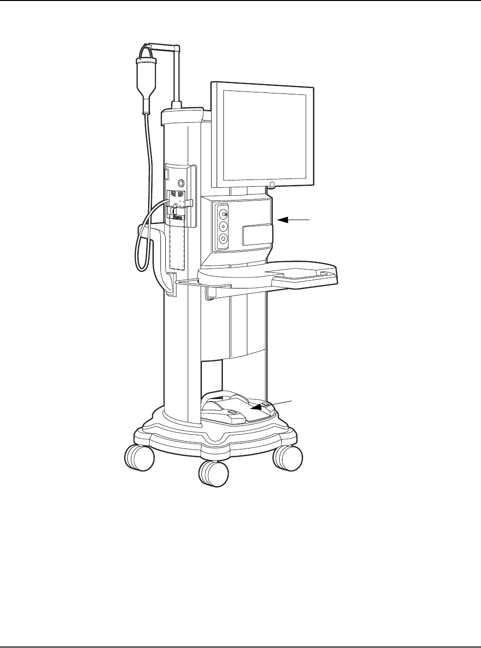
Figure 2.1 – WHITESTAR SIGNATURE™ System
1. Programmable IV Pole 4. WHITESTAR SIGNATURETM System console
with Integral Cart and Mayo Tray
2. FUSIONTM Tubing Cassette
3. Wireless Remote Control Module (Storage bay on
top of the system) 5. Footpedal
1
2
3
4
5
2 • System Components
WHITESTAR SIGNATURE™ System Rx Only – Z370147 Rev. C 1108 2-4
WHITESTAR
SIGNATURE™
System with
FUSION™ Tubing
Pack
Each surgical procedure requires a disposable FUSION™ Tubing Cassette for
either the peristaltic pump or the Venturi pump. The FUSION™ Tubing Cassette
only works with the peristaltic pump, which is used in anterior/cataract surgeries.
The Dual Pump Tubing Cassette works with both the peristaltic pump and the
Venturi pump. With the Fusion™ Dual Pump Pack you can select either pump
while you are in a surgical case.
The tubing pack contains the following components:
• Tubing cassette with irrigation and aspiration tubing (administration set) with an
attached, sealed drain bag
• Infusion Sleeve
• Test Chamber – to test and prime/tune the phaco handpiece
• Mayo Stand Drape – to cover the Mayo tray and arm
• Monitor Drape – to cover the front of the touch screen
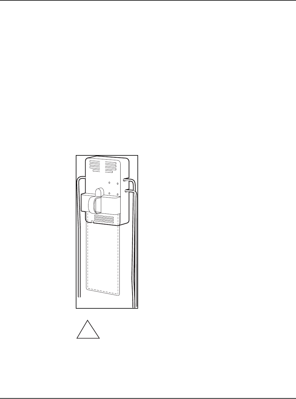
Figure 2.2 – FUSION™ Tubing Cassette
Proper handling and disposal methods for biohazards must be used when
you dispose of the tubing cassette, Mayo stand drape and monitor drape.
!

WHITESTAR SIGNATURE™ System Rx Only – Z370147 Rev. C 1108 3-1
Safety Precautions
Warnings
Symbol Definitions
System Disposal
Setup Sequence – Anterior Segment Surgery
Footpedal
Programmable IV Pole
Wireless Remote Control (Optional)
Surgical Media Center (SMC) (Optional)
Shutdown Sequence – Anterior Segment Surgery
3SYSTEM SETUP

3 • System Setup
WHITESTAR SIGNATURE™ System Rx Only – Z370147 Rev. C 1108 3-2
Safety Precautions Now that the system is set up and you have verified that all of the functions are
operating properly, you are almost ready to use your WHITESTAR
SIGNATURE™ System.
Read the following Safety Precautions and Warnings carefully before you use the
WHITESTAR SIGNATURE™ System in surgery.
1. The WHITESTAR SIGNATURE™ System is equipped with 3-prong power
plug which must be plugged into an outlet with a ground receptacle.
If the plug does not fit the outlet, contact an electrician. DO NOT modify or
remove the ground pin.
2. Do not use extension cords with your system.
3. Do not overload your electrical receptacle (outlet).
4. If the cord or plug is damaged, do not use the instrument. An electric shock or
fire hazard can result. Call AMO customer service to order a new cord.
5. The instrument has ventilation openings at the rear of the console to allow
ambient air intake and the release of heat generated during operation. If the
openings are blocked, heat build-up can cause system failures which can result
in a fire hazard.
6. Do not try to move the WHITESTAR SIGNATURE™ System cart on deep
pile carpets or over objects on the floor such as cables and power cords.
7. Take care not to trip over power and footpedal cords.
8. Do not try to lift the WHITESTAR SIGNATURE™ System cart.
9. Do not place the instrument on uneven or sloped surfaces.
10. Do not use disposables, accessories or other surgical instruments that are not
designed for this system. Use only parts recommended by AMO to achieve
optimum performance and safety.
11. Do not operate the WHITESTAR SIGNATURE™ System in a condensing
environment. Take care to protect the instrument from fluid sprays or fluid
buildup.
12. To protect the patient from contaminated fluids or handpieces, use only:
• sterile tubing cassettes
• sterile irrigation fluid
• sterile handpieces
13. Use caution when you extend, retract or swivel the Mayo stand articulating
arm. Stay clear of the hinged hardware.
14. Use caution when you use handpieces with sharp edges or pointed tips.

3 • System Setup
WHITESTAR SIGNATURE™ System Rx Only – Z370147 Rev. C 1108 3-3
15. Always replace the tubing cassette between cases.
16. Wrap the excess power cord neatly around the cord wrap on the back of the
console.
Changing Irrigation Flow
Use extreme caution when you lower or raise the balanced salt solution bottle to
decrease or increase fluid flow and pressure. If you lower the bottle too much it can
cause the anterior chamber to collapse. If you raise the bottle too high it can cause
the anterior chamber to deepen. To make sure that the bottle height does not go too
high, you can set the maximum bottle height on the Diagnostics screen.
Note: Use a new bottle of balanced salt solution at the start of each case.
Phacoemulsification without Adequate Irrigation
Operating phacoemulsification without an adequate irrigation flow can result in an
elevated temperature of the tip and subsequent damage to the eye tissue or could
cause the chamber to collapse. Confirm that there is irrigation flow before you
initiate phacoemulsification. A tight wound or the angle of the needle next to the
wound can also constrict the irrigation flow by pinching the coaxial irrigation
sleeve assembly on the needle of the phaco handpiece.
Power Failure during Surgery
If there is a loss of power during a procedure, you need to:
• Withdraw the handpiece from the eye
• Release the footpedal to Position 0
When power is restored:
• Select Prime/Tune to reprime the fluids and tune the phaco handpiece. Use
Bypass to reduce the length of prime time.
• Select the mode that was in use when power was lost (PHACO, IA, Vitrectomy
or Diathermy)
Connecting Handpieces
It is very important that the electrical connectors on the handpieces are completely
dry before they are connected to the WHITESTAR SIGNATURE™ System
receptacles. You can receive a “Handpiece Ground Fault Error” message if the
connector is wet.
Handling the Phaco Handpiece
The phaco handpiece is a very delicate instrument and must be handled with
EXTREME care. If the handpiece is dropped or receives any other significant
impact, the handpiece will not work properly. The ultrasonic titanium phaco tip
must never touch any solid material while in use.
Always flush the handpiece immediately following surgery.

3 • System Setup
WHITESTAR SIGNATURE™ System Rx Only – Z370147 Rev. C 1108 3-4
See cleaning instructions given in Chapter 9, “Care and Cleaning”.
Handpieces can be extremely hot immediately after sterilization. Use care and
caution when handling.
Phaco and Vitrectomy Operation
The phaco handpiece and the vitrectomy cutter must never be activated with the
tips exposed to air. If the tips are activated in the air, the useful life of the handpiece
and the cutter is reduced. If power is to be introduced to the phaco handpiece or the
vitrectomy cutter, the tips must be in a test chamber filled with a balanced salt
solution, in a container of balanced salt solution, or in the patient's eye.
Vitrectomy
Failure to properly attach the tubing to the appropriate vacuum or pressure source
can affect the vitrectomy cutter operation. Be sure to read the vitrectomy cutter
package insert for correct assembly and connection procedures.
Diathermy
When you enter the Diathermy mode, an audible tone should be heard. Also,
whenever diathermy power is applied, an audible tone should be heard.
The diathermy cable must be checked periodically for damage. If the cable shows
signs of damage, replace the cable immediately with the same type of cable. Use of
other types of cables can affect the diathermy performance.
During surgery, the diathermy output power must be as low as possible for the
intended purpose. AMO recommends the 30% setting to start.
The diathermy cable must be positioned in such a way that contact with the patient
or other leads is avoided. Grounded or ungrounded metal parts must not come in
contact with the patient when diathermy is used.
For proper operation of the diathermy, replace the handpiece with the same type.
Programmable IV Pole
Do not exceed the maximum weight of two 500 ml balanced salt solution bottles on
the IV pole bottle holder.
Wireless Remote Control and Wireless Foot Pedal
These devices comply with part 15 of the FCC (Federal Communications
Commission) Rules. Operation is subject to the following two conditions:
1. This device may not cause harmful interference.
2. This device must accept any interference received, including interference that
may cause undesired operation.
Any changes or modifications not expressly approved by Advanced Medical
Optics, Inc. can void the user's authority to operate the equipment.

3 • System Setup
WHITESTAR SIGNATURE™ System Rx Only – Z370147 Rev. C 1108 3-5
Note: This equipment has been tested and found to comply with the limits for a
Class A digital device, pursuant to part 15 of the FCC Rules. These limits
are designed to provide reasonable protection against harmful interference
when the equipment is operated in a commercial environment. This
equipment generates, uses, and can radiate radio frequency energy and, if
not installed and used in accordance with the instruction manual, may cause
harmful interference to radio communications. Operation of this equipment
in a residential area is likely to cause harmful interference in which case the
user will be required to correct the interference at his own expense.
Warnings
WARNING: All personnel who might operate this equipment must read
and understand the instructions in this manual before the system is used. Failure to
do so might result in the improper operation of the system. This device is only to be
used by a trained licensed physician.
WARNING: The fluid level in the balanced salt solution bottle must be
monitored by the surgical nursing staff. The result of a low bottle or an empty bottle
affects the fluid balance and the intra-ocular pressure (IOP) while aspirating. The
low or empty bottle can result in:
• The inadvertent chamber shallowing or collapse
• The Aspiration of tissue
• An ultrasonic wound heating commonly called wound burn (extreme case)
The surgical staff must monitor the fluid level at all times.
WARNING: DO NOT attempt to use the system if the system fails to
perform properly as stated in this manual.
WARNING: DO NOT use the System in the presence of flammable
anesthetics, or other flammable gases, near flammable fluids or objects, or in the
presence of oxidizing agents, as a fire could result.
!
!
!
!

3 • System Setup
WHITESTAR SIGNATURE™ System Rx Only – Z370147 Rev. C 1108 3-6
WARNING: This unit might interfere with any cardiac pacemaker fitted
to the patient; therefore qualified advice must be obtained prior to such use.
WARNING: The patient must not come into contact with metal parts
which are grounded or have appreciable capacitance to ground. The use of an
antistatic mat for this purpose is recommended.
WARNING: Proper handling and disposal methods for biohazards must
be used when you dispose of the tubing cassette, mayo stand drape and monitor
drape.
WARNING: Monitoring electrodes or other types of equipment must be
placed as far from those of the WHITESTAR SIGNATURE™ System as possible.
High current limiting devices are recommended for the protection of such systems.
Needle monitoring electrodes are not recommended.
WARNING: Keep the diathermy cord away from the patient and other
handpieces or leads (for example, monitoring electrodes).
WARNING: The output power selected must be as low as possible for
the intended purpose.
WARNING: Although this unit complies with all Electromagnetic
Interference (EMI) standards and requirements, it is possible that interference
provided by the operation of the HIGH FREQUENCY (HF) SURGICAL
EQUIPMENT can adversely influence the operation of other electronic equipment.
!
!
!
!
!
!
!

3 • System Setup
WHITESTAR SIGNATURE™ System Rx Only – Z370147 Rev. C 1108 3-7
WARNING: Skin to skin contact on the patient, for example, between
the arms and the torso is not recommended. Insert dry gauze to avoid contact, as
appropriate.
Note: The unit does not contains any neutral electrode.
Note: The diathermy output is bipolar.
Note: It is recommended that the condition of all inter-connecting and handpiece
cables be checked on a regular basis.
WARNING: Risk of burns and fire. Do not use the system near
conductive materials such as metal bed parts, inner spring mattresses, or similar
items. Replace electrode cables on evidence of deterioration.
WARNING: Hazardous electrical output. This equipment is for use only
by qualified personnel.
WARNING: Disconnect the power before you service the equipment.
WARNING: Remove the power cord from the power outlet when the
equipment is not in use.
WARNING: Do not obstruct the power outlet so that the power cord can
be readily removed, as needed.
WARNING: Not recommended for use in condensing environments. If
exposed to a condensing environment, allow the system to equilibrate to typical
operating room conditions prior to use.
!
!
!
!
!
!
!

3 • System Setup
WHITESTAR SIGNATURE™ System Rx Only – Z370147 Rev. C 1108 3-8
WARNING: This HIGH FREQUENCY (HF) SURGICAL
EQUIPMENT is specified for use without a NEUTRAL ELECTRODE.
WARNING: Failure of the HIGH FREQUENCY (HF) SURGICAL
EQUIPMENT could result in an unintended increase of output power.
WARNING: DO NOT try to replace the Wireless Remote Control
batteries. Call your AMO Technical Service representative to replace the batteries.
WARNING: Sterility assurance is the responsibility of the user. All non-
sterile accessories must be sterilized prior to use.
WARNING: Prior to using any invasive portions of the handpiece
assembly, examine under the microscope for any obvious damage, oxidation, or the
presence of foreign material. If any questionable characteristics are noted, use a
backup handpiece for surgery. Use of contaminated or damaged system accessories
can cause patient injury.
WARNING: Use of non-AMO approved products with the
WHITESTAR SIGNATURE™ System, can affect overall system performance and
is not recommended. AMO cannot be responsible for system surgical performance
if these products are utilized in surgery.
!
!
!
!
!
!
3 • System Setup
WHITESTAR SIGNATURE™ System Rx Only – Z370147 Rev. C 1108 3-9
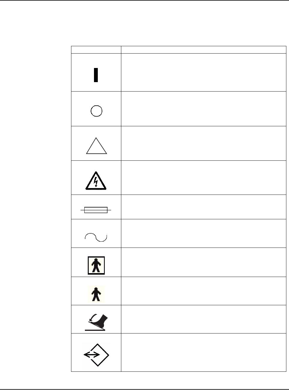
Symbol Definitions The following symbols appear on the WHITESTAR SIGNATURE™ System front
and back panels and in the software:
Table 3.1 – Symbol Definitions
Symbol Definition
Symbol on power switch indicates Power is On.
Symbol on power switch indicates Power is Off.
Indicates that there are important operating and
maintenance instructions included in the Owner’s and
Operator’s Manual.
Indicates the presence of uninsulated high voltage inside
the instrument. Risk of electric shock. Do not remove the
instrument cover.
Indicates fuse.
Single phase alternating current.
Patient applied part is isolated from earth ground.
Patient applied part is grounded OR no direct electrical
energy is involved.
Footpedal connection.
Communications Port
!
3 • System Setup
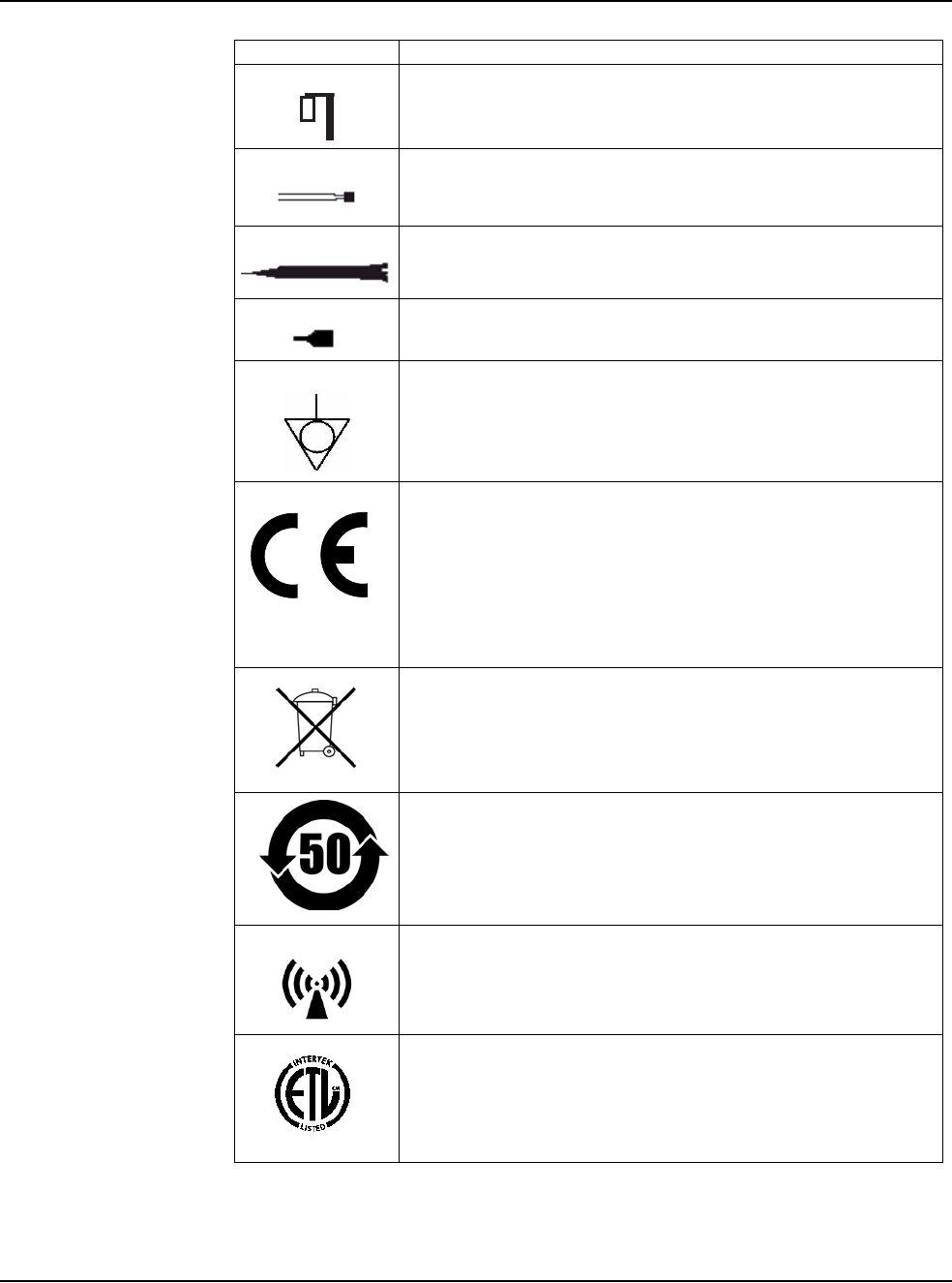
WHITESTAR SIGNATURE™ System Rx Only – Z370147 Rev. C 1108 3-10
Programmable IV Pole
Diathermy Receptacle
Phaco Handpiece Receptacle
Vitrectomy Cutter Connection
Potential Equalizer
Indicates compliance with the Medical Device Directive.
Separate Disposal/Collection Required
Environment Friendly Use Period in Years (RoHS)
Indicates compliance with IEC 60601-1-2:2001,
“Electromagnetic Compatibility Requirements and Tests
for Medical Electrical Equipment.”
ETL Listed Mark issued to those products that have met the
requirements of product safety standards for the United
States and Canada. (ETL formerly Edison Testing
Laboratory)
Symbol Definition
0050
3 • System Setup
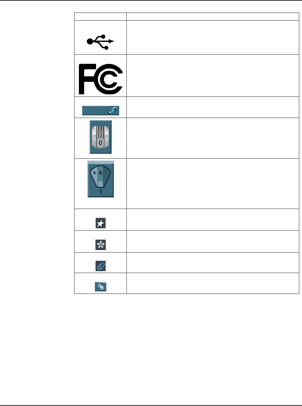
WHITESTAR SIGNATURE™ System Rx Only – Z370147 Rev. C 1108 3-11
Universal Serial Bus (USB) Port
Note: Use only AMO recommended USB stick drives.
Federal Communications Commission (FCC)
The FCC regulates interstate and international
communications by radio, television, wire, satellite and
cable under the FCC’s jurisdiction.
FUSION™ Mode button used to open the CASE settings
screen.
Single Linear Foot Pedal Icon. Shows the position of the
footpedal when the footpedal is pressed. The number
shown changes when the position is changed.
Advanced Control Pedal (Dual Linear) Icon. Shows the
position of the footpedal when the footpedal is pressed. The
number shown changes when the position is changed. The
letters indicate the location of Aspiration (A), Irrigation (I),
Phaco (P), Reflux (R), Whitestar Increment/Decrement
(WS) and Switch (S).
WHITESTAR® Technology is On.
WHITESTAR® Technology is On and ICE Pulse Shaping
is On.
Ellips™ Technology is On.
Reload button is used to cycle through the surgeon’s
programs.
Symbol Definition

3 • System Setup
WHITESTAR SIGNATURE™ System Rx Only – Z370147 Rev. C 1108 3-12
System Disposal WEEE
The electronic components of the WHITESTAR SIGNATURE™ System are
subject to the European Union Directive 2002/96/EC on Waste Electrical and
Electronic Equipment. This directive applies to all electronic equipment in the
European Union only.
The disposal to municipal waste is prohibited for electronic equipment subject to
this directive; this equipment must be treated or recycled. Each component that is
subject to this regulation is marked on the component itself with the following
symbol:
In some cases where the component’s size prohibits marking (such as handpieces)
the marking can be found on the directions for use and the warranty. Treatment
and/or recycling of the electronic equipment are provided at no cost to you. Please
see the contact information below for disposition of unwanted AMO electronic
equipment.
For disposal of your unit, contact your local AMO subsidiary or the AMO service
center nearest you.
Belgium
Contact
De Ceunynck Medical
nv/sa
Kontichsesteenweg 36
B-2630 AARTSELAAR
Belgium
Denmark
Distributor
AMO Denmark ApS
c/o Advanced Medical Optics
Norden AB
Kanalvagen 3A
SE 194 61 Upplands Vasby
Sweden
Finland
AMO Norden AB
Vantaa/Finland
Rajatorpantie 41 C, 3. krs
FIN-01640 Vantaa
Finland
Phone: +358 9 8520 2192
France
AMO France SAS
Greenside 15,
750 Avenue de Roumanille
06410 Biot
France
Phone: +33 4 93 00 11 95

3 • System Setup
WHITESTAR SIGNATURE™ System Rx Only – Z370147 Rev. C 1108 3-13
Germany
AMO Germany GmbH
Rudolf-Plank Strasse 31
D-76275 Ettlingen
Germany
Phone: +49 7243 729 444 (Hotline)
Greece
Distributor
Nexus Medicals s.a.
12th km Nat. Road Ave Athens-
Lamia & Zakynthou str.
14451 Metamorfosi
Athens
Greece
Ireland
AMO Ireland
Block B
Liffy Valley Office Campus
Quarryvale,
Co. Dublin
Ireland
Italy
AMO Italy Srl
Via Pio Emmanuelli, n.1
00143 Rome
Italy
Phone: +39 06 51 29 61
Netherlands
AMO Netherlands B.V.
Kantoorgebouw La Residence
Weverstede 25
3431 JS Nieuwegein
The Netherlands
Phone: +31 (0)30 600 8787
Norway
Distributor
Advanced Medical Optics
Norway AS
c/o Advanced Medical Optics
Norden AB
Kanalvagen 3A
SE 194 61 Upplands Vasby
Sweden
Poland
Distributor
Oko-Vita Polska sp.z.o.,
ul Marywilska 34,
03-228 Warsaw,
Poland
Portugal
Advanced Medical Optics Spain
S.L.
sucursal em Portugal
Praca Nuno Rodreguez dos Santos
no 7, 1600-171
Lisboa
Portugual
Russia
Distributor
Tradomed Ltd.,
Marksistskaya Str. 3,
Bld 1,
Moscow,
109147,
Russia
Spain
Advanced Medical Optics
Spain, S.L.
c/Dr. Zamenhof, n. 22, 4B
28027 Madrid
Spain
Phone: +34 9176 88 000

3 • System Setup
WHITESTAR SIGNATURE™ System Rx Only – Z370147 Rev. C 1108 3-14
RoHS (Restriction of Hazardous Substances)
For Chinese Regulation: Administrative Measure on the Control of Pollution
Caused by Electronic Information Products
Sweden
Advanced Medical Optics
Norden AB
Kanalvagen 3A
SE 194 61 Upplands Vasby
Sweden
Switzerland
Distributor
AMO Switzerland GmbH,
Churerstrasse 160 B,
CH-8808 Pfäffikon,
Switzerland
United Kingdom
AMO United Kingdom Ltd
Jupiter House
Mercury Park
Wooburn Green
High Wycombe
Buckinghamshire
HP10 0HH United Kingdom
Phone: +44 1628 551600
Table 3.2 – Names and Content of Toxic and Hazardous Substances or
Elements
Parts Name Toxic and Hazardous Substances or Elements
Pb Hg Cd Cr6+ PBB PBDE
Housing x o o x o o
Power Supply x o o x x x
Motherboard xooo x x
Rear Panel
Assembly Board xoox x x
Pneumatics x o o x o o
LCD xxoo x x
Base Unit x o o o x x
Fluidics xoox o o
o: Indicates that this toxic or hazardous substance contained in all of the
homogeneous materials for this part is below the limit requirement in SJ/
T11363-2006
x: Indicates that this toxic or hazardous substance contained in at least one of
the homogeneous materials used for this part is above the limit requirement in
SJ/T11363-2006 (Enterprises may further provide in this box technical
explanation for marking "X" based on their actual conditions.)

3 • System Setup
WHITESTAR SIGNATURE™ System Rx Only – Z370147 Rev. C 1108 3-15
Setup Sequence –
Anterior Segment
Surgery
The following is a general overview of the steps to be taken to prepare the
WHITESTAR SIGNATURE™ System for surgery:
1. Connect the WHITESTAR SIGNATURE™ System power cord to the rear of
system. Plug the power cord into a grounded power outlet.
2. Connect the footpedal to the rear panel receptacle.
3. Connect the compressed air line to the compressed air receptacle (optional).
4. Turn the system On at the back of the console.
5. Press the On/Off button on the Touch Screen monitor.
6. After completion of the Start Up Self Test, select the surgeon and program.
7. Install the tubing cassette, attach the required accessories (phaco, vitrectomy or
diathermy handpieces) and set up the tubing.
8. Prime and tune the handpieces. (Refer to Chapter 4, Equipment Operation,
Prime/Tune.)
9. Perform the final test of the fluidics and the handpiece integrity with the
footpedal. (Refer to Chapter 4, Equipment Operation, Verify Irrigation/
Aspiration Balance.)

3 • System Setup
WHITESTAR SIGNATURE™ System Rx Only – Z370147 Rev. C 1108 3-16
Figure 3.1 – Rear Panel Connections
Phacoemulsification Ultrasonic Handpiece
WARNING: Sterility assurance is the responsibility of the user. All non-
sterile accessories must be sterilized prior to use.
WARNING: Prior to using any invasive portions of the handpiece
assembly, examine under the microscope for any obvious damage, oxidation, or the
presence of foreign material. If any questionable characteristics are noted, use a
backup handpiece for surgery. Use of contaminated or damaged system accessories
can cause patient injury.
1. Use caution to prevent burns when handling the handpiece directly from
sterilization.
2. Remove the tubing cassette and accessories from the tubing pack and place
them in the sterile area.
1. USB Port 4. Compressed Air
2. Communications Port 5. Potential Equalizer
3. Foot Pedal Connector 6. Power Switch and Power Cord Connection
1
2
3
4
5
6
!
!
3 • System Setup
WHITESTAR SIGNATURE™ System Rx Only – Z370147 Rev. C 1108 3-17
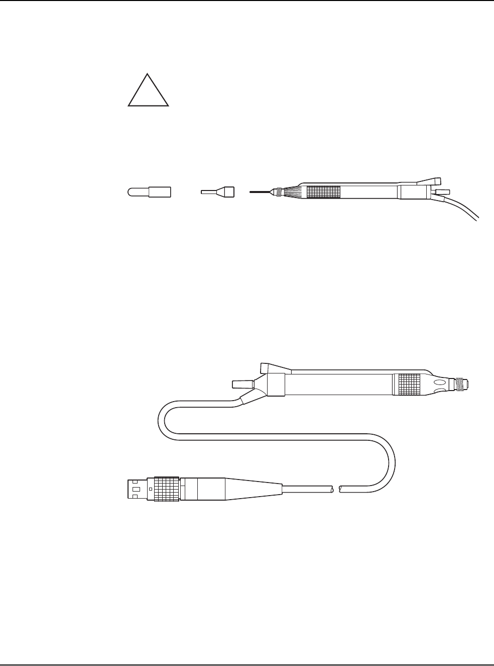
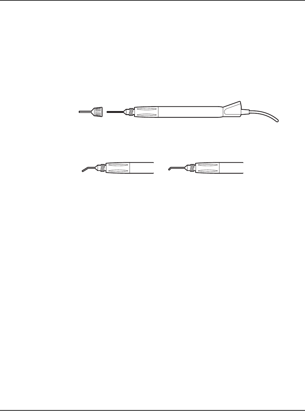
3. Assemble the phaco handpiece as shown below. You need the handpiece,
titanium phaco tip, the appropriate tip wrench, one of the infusion sleeves and
the test chamber.
CAUTION: NEVER ATTEMPT TO STRAIGHTEN A BENT
NEEDLE. THIS MIGHT PRODUCE A BROKEN TIP WHEN
ULTRASOUND IS APPLIED.
Figure 3.2 – Phaco Handpiece Assembly
4. Attach the connector end of the handpiece to the phaco receptacle on the front
of the WHITESTAR SIGNATURE™ System. Make sure there is no
moisture on the connectors prior to connecting. Moisture prevents the
handpiece from operating properly.
Figure 3.3 – Ellips™ Handpiece
Note: The Ellips™ handpiece can be used with WHITESTAR® Technology and
Ellips™ Technology phaco settings.
1. Test Chamber
2. Infusion Sleeve
3. Handpiece with Tip
!
12 3
3 • System Setup
WHITESTAR SIGNATURE™ System Rx Only – Z370147 Rev. C 1108 3-18
Irrigation/Aspiration Handpiece
1. Assemble the SOLO™ Irrigation/Aspiration (IA) Handpiece by attaching the
infusion sleeve.
Note: The infusion sleeve and the test chamber are provided in the
FUSION™ Tubing Pack. The LAMINAR™ Flow 20 ga. infusion
sleeves can also be used and are available with the OPOS20L or any
20 ga. LAMINAR™ Phaco Tip.
Figure 3.4 – IA Handpiece Assembly
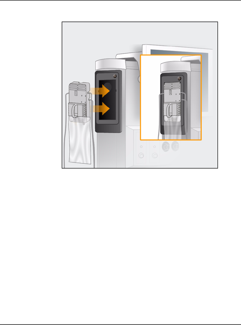
Load the FUSION™ Tubing Cassette
1. Open the tubing pack packaging.
2. Install the FUSION™ cassette into the side receptacle, as shown below.
3. Make sure that the drainage bag is properly attached to the cassette.
12
4
3
5
1. Infusion Sleeve 4. SOLOTM Curved Tip
2. SOLOTM Straight Tip 5. SOLOTM 45o Silicone Sleeve Tip
3. Handpiece
3 • System Setup
WHITESTAR SIGNATURE™ System Rx Only – Z370147 Rev. C 1108 3-19
Figure 3.5 – Loading the FUSION™ Tubing Cassette
Note: Press the button above the cassette to remove the cassette.
Setup Completion
IMPORTANT! Before you insert the spike into the bottle, shake the irrigation drip
chamber at the end of the irrigation tubing to confirm that the irrigation valve
moves. If the valve does not rattle, the valve cannot operate properly and irrigation
cannot flow.
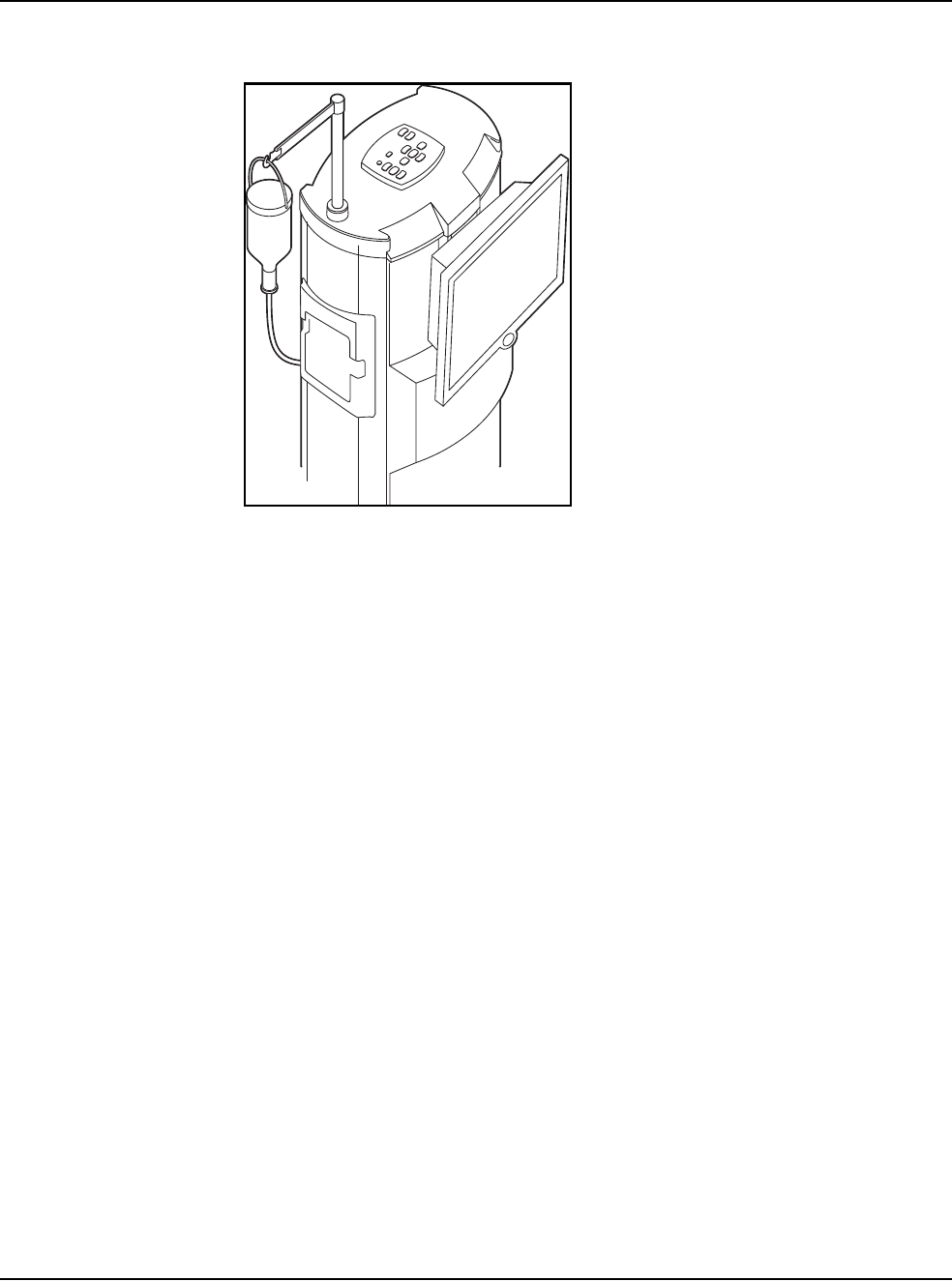
1. Place a new bottle of balanced salt solution on the top of the system console.
2. Insert the drip chamber spike into the balanced salt solution bottle.
3. Hang the balanced salt solution bottle from the Programmable IV Pole and
squeeze the drip chamber.
4. Fill the drip chamber with fluid to the half-full level. The Programmable IV
Pole moves to the appropriate height automatically.
5. Raise or lower the pole if needed. Use the IV pole Up and Down arrows on
upper right of the touch screen. You can also use the Up/Down switch on the
console.
3 • System Setup
WHITESTAR SIGNATURE™ System Rx Only – Z370147 Rev. C 1108 3-20
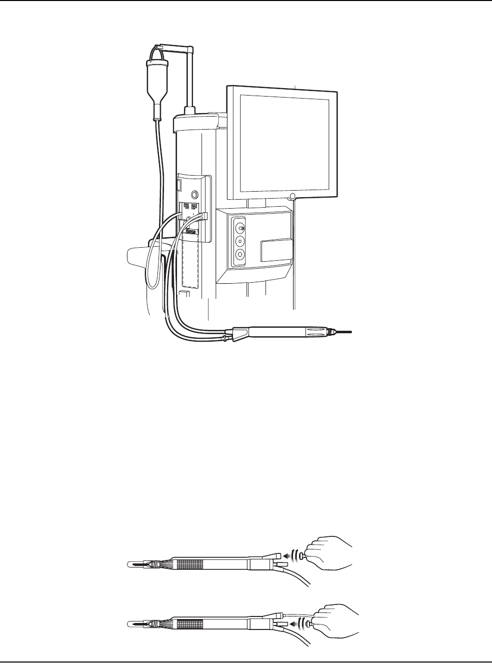
Figure 3.6 – System Setup
6. Connect the IA tubing to the desired handpiece.
7. Insert the male luer end of the irrigation tubing into the phaco handpiece.
8. Attach the female luer fitting end of the aspiration tubing to the phaco
handpiece.
Note: To protect the patient from contamination, use only:
• sterile tubing sets
• sterile irrigation fluid
• sterile handpieces
Figure 3.7 – Phaco Handpiece Connections
3 • System Setup
WHITESTAR SIGNATURE™ System Rx Only – Z370147 Rev. C 1108 3-21
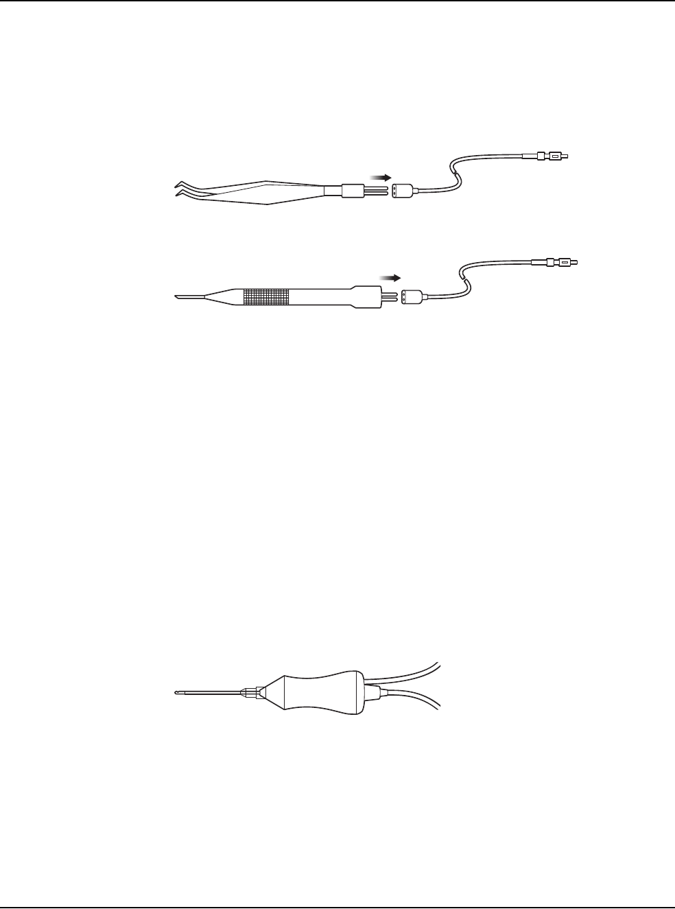
Diathermy
1. Connect the diathermy cord to the Diathermy Forceps or Pencil Probe.
2. Connect the diathermy cord to the diathermy receptacle on the front panel.
Figure 3.8 – Diathermy Forceps
Figure 3.9 – Diathermy Pencil
Note: Other diathermy accessories are regionally available. Contact your AMO
representative.
Vitrectomy
If vitrectomy is indicated during surgery:
1. Connect the AMO® Vitrectomy Cutter as shown below. Vitrectomy requires
the following components:
• IA Tubing (from FUSION™ Tubing Cassette)
• Vitrectomy Cutter
• Vitrectomy Infusion Sleeve, or a 23 Gauge Limbal Infusion Needle, if
desired.
2. Assemble the handpiece using the instructions provided with the vitrectomy
cutter.
Figure 3.10 – Vitrectomy Cutter
3. Attach the connector end of the vitrectomy cord to the vitrectomy receptacle on
the front panel.
3 • System Setup
WHITESTAR SIGNATURE™ System Rx Only – Z370147 Rev. C 1108 3-22
Pre-Operative Sterilization
The Instrument Sterilization Procedures in Chapter 9, “Care and Cleaning” identify
the WHITESTAR SIGNATURE™ System instruments that must be sterilized prior
to each surgical case. The recommended sterilization techniques, times and
temperatures are given in Chapter 9, “Care and Cleaning”. AMO recommends that
you follow the sterilization guidelines to maximize the life of your WHITESTAR
SIGNATURE™ System instruments.
Footpedal The footpedal controls all of the WHITESTAR SIGNATURE™ System functions,
therefore, it is essential that you understand the footpedal operation.
The System software automatically detects if a footpedal and what type of
footpedal is connected during power up.
The footpedal settings and adjustments can be selected and preset for the footpedal
in the Configuration screen. Instructions for the footpedal settings are given in
Chapter 5, “Anterior Segment Surgery Operating Modes”. The footpedal housing
incorporates a handle, making the footpedal easy to grip for repositioning and
storage.
The Footpedal cable attaches to the footpedal connector on the rear of the console.
The Advanced Control Pedal (dual linear) can also be setup with a wireless
connection.
Note: You must NEVER handle the footpedal by the cable.
WARNING: Use only NiMH type batteries in the wireless Advanced
Control Pedal.
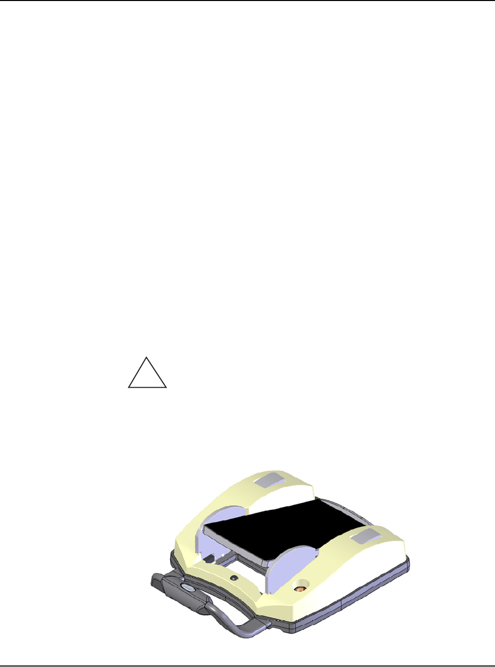
Figure 3.11 – Footpedal - Single Linear
!
3 • System Setup
WHITESTAR SIGNATURE™ System Rx Only – Z370147 Rev. C 1108 3-23
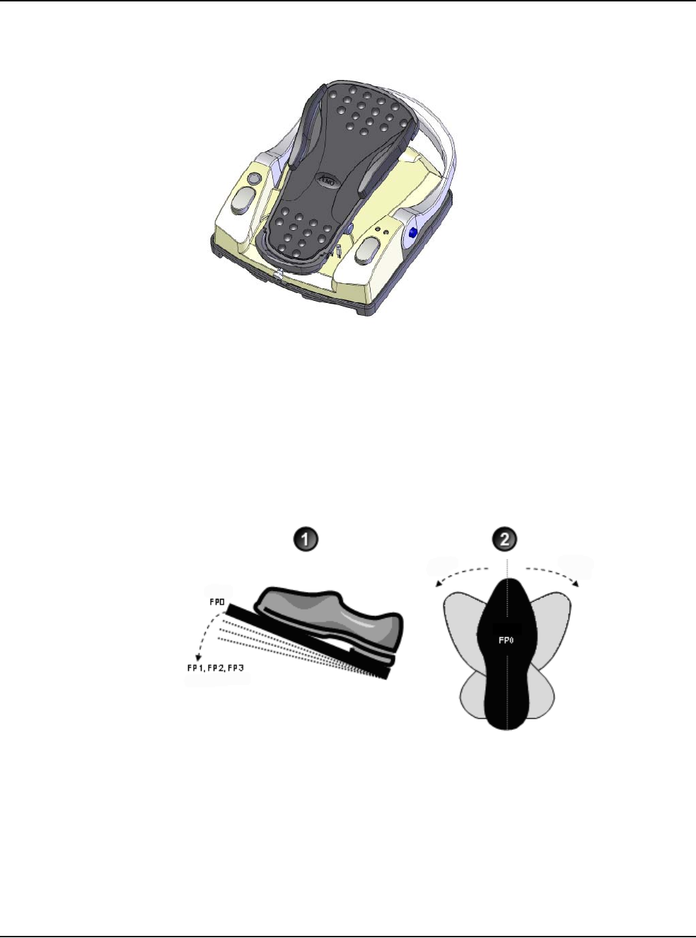
Figure 3.12 – Footpedal - Advanced Control Pedal (Dual Linear)
Footpedal Operation
The footpedal has three active “PITCH” ranges, which are referred to as Positions
1, 2 and 3. Position 0 is the Off position, and Position 3 is the fully pressed position.
The ranges are shown below. The Advanced Control Pedal has two Yaw switches.
Figure 3.13 – Footpedal “Pitch” and “Yaw” Positions
The footpedal position determines the function that is delivered by the handpiece,
which depends on the mode selected on the touch screen. When the footpedal has
been connected, place your foot on the pedal and press to the desired position. The
footpedal settings and programming are addressed in Chapter 5, “Anterior Segment
Surgery Operating Modes”.
1. Pitch 2. Yaw
Toe Down/Up Toe Right/Left
Configurable Ranges Configurable Ranges

3 • System Setup
WHITESTAR SIGNATURE™ System Rx Only – Z370147 Rev. C 1108 3-24
Note: Four to six minutes after the system is shutdown and power is turned off,
the wireless footpedal goes into a power-save mode. To turn on the
Wireless Footpedal after you start up the system, touch the Wake-up
button.
Reflux
Reflux is the controlled backflow of fluid through the aspiration port of the
handpiece. Reflux is used to gently release or dislodge unwanted material from the
handpiece tip. Reflux can also be used to “tent” the incision site to allow easier tip
insertion. Reflux pressure depends on bottle head pressure (IV pole height and
gravity) for the FUSION™ Fluidics pack (OPO70), and as such, is not intended to
clear a clogged handpiece. However, reflux can be used to identify a blockage.
The reflux action can be programmed on any available footpedal switch. This
causes fluid to be expelled from the aspiration line into or towards the eye.
The reflux is active until the footpedal switch is released.
The FUSION™ Fluidics pack (OPO70):
• allows an inter-connection of the irrigation line to the aspiration line, so that
sterile balanced salt solution can enter the aspiration line.
• has no time restriction for Reflux as there is no pump reversal
The DP pack (OPO71):
• includes support for the vacuum tank used in the Venturi vacuum system
• does not support inter-connecting the irrigation line to the aspiration line.
Therefore, only previously aspirated fluid is being refluxed.

3 • System Setup
WHITESTAR SIGNATURE™ System Rx Only – Z370147 Rev. C 1108 3-25
Programmable IV
Pole The Programmable IV Pole is controlled by the Up and Down arrows on the upper
right of the touch screen, next to the bottle height indicator. The buttons on the
remote control and the switch on the side of the console can also be used to control
the IV Pole. These controls are used to raise and lower the pole, and the height is
indicated in the Programmable IV Pole screen. The Programmable IV Pole moves
at a rate of approximately 6 cm (2 inches) per second.
The Programmable IV Pole is adjustable from 0 to 104 centimeters, and can be set
for either inches or centimeters. The height measurement is relative to the distance
from the irrigation valve to the center of the drip chamber. The Programmable IV
Pole height for each fluidic mode or submode (PHACO, IA, VIT) is saved in the
WHITESTAR SIGNATURE™ System memory. A Maximum IV Pole height can
be set on the Diagnostics screen.
When a surgery mode is selected, the Programmable Power IV Pole automatically
moves to the preset height. To manually adjust the IV pole height, use the Up and
Down arrows on the touch screen. Manual adjustments to the IV pole can also be
made by pressing the rocker switch located on the side of the console. If a
maximum height has been set, the IV pole will not move above that height.
3 • System Setup
WHITESTAR SIGNATURE™ System Rx Only – Z370147 Rev. C 1108 3-26
Wireless Remote
Control (Optional) The wireless remote control keypad can be used to operate the WHITESTAR
SIGNATURE™ System. All Modes, Programs, Diagnostics and End Case can be
accessed and adjustments to the settings can be made with the remote control. The
buttons on the remote keypad work the same as the controls on the WHITESTAR
SIGNATURE™ System touch screen.
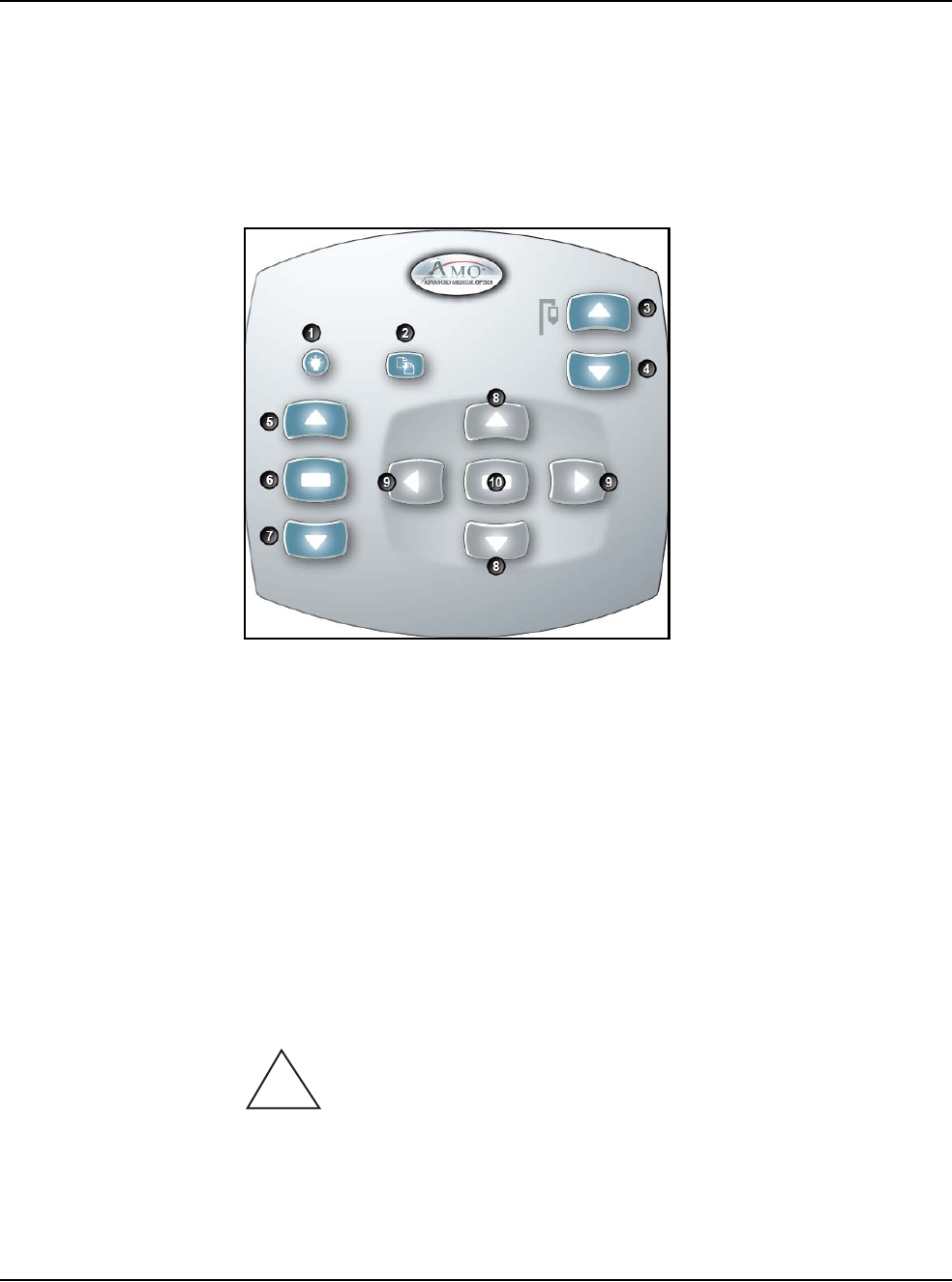
Figure 3.14 – Wireless Remote Control Module
When not in use, store the Wireless Remote Control on the top of the system to
charge the batteries.
After you turn the system On, press the Remote Control Backlight button to
activate the Remote Control. When the system is Off the Remote Control is in a
power save mode.
Note: After four to six minutes of idle time, the Remote Control goes into a power-
save mode. To turn the Remote Control on, press the Backlight button.
WARNING: DO NOT try to replace the Wireless Remote Control
batteries. Call your AMO Technical Service representative to replace the batteries.
1. Remote Backlight On 6. Mode Select
2. Reload 7. Mode Down
3. IV Pole Up 8. Navigation Up/Down
4. IV Pole Down 9. Navigation Left/Right
5. Mode Up 10. Select
!
3 • System Setup
WHITESTAR SIGNATURE™ System Rx Only – Z370147 Rev. C 1108 3-27
Figure 3.15 – Wireless Remote Control Module Storage
Surgical Media
Center (SMC)
(Optional)
The Surgical Media Center (SMC) is used to record the surgery and the instrument
settings to be viewed at a later date and time. The surgery is displayed on a monitor
with the instrument settings. The SMC hardware is connected to your
WHITESTAR SIGNATURE™ System Communications port on the rear panel.
(See Figure 3.1 Rear Panel Connections.)
1. To configure the Surgical Media Center, select:
• Configuration
• System Configuration
•SMC
3 • System Setup
WHITESTAR SIGNATURE™ System Rx Only – Z370147 Rev. C 1108 3-28
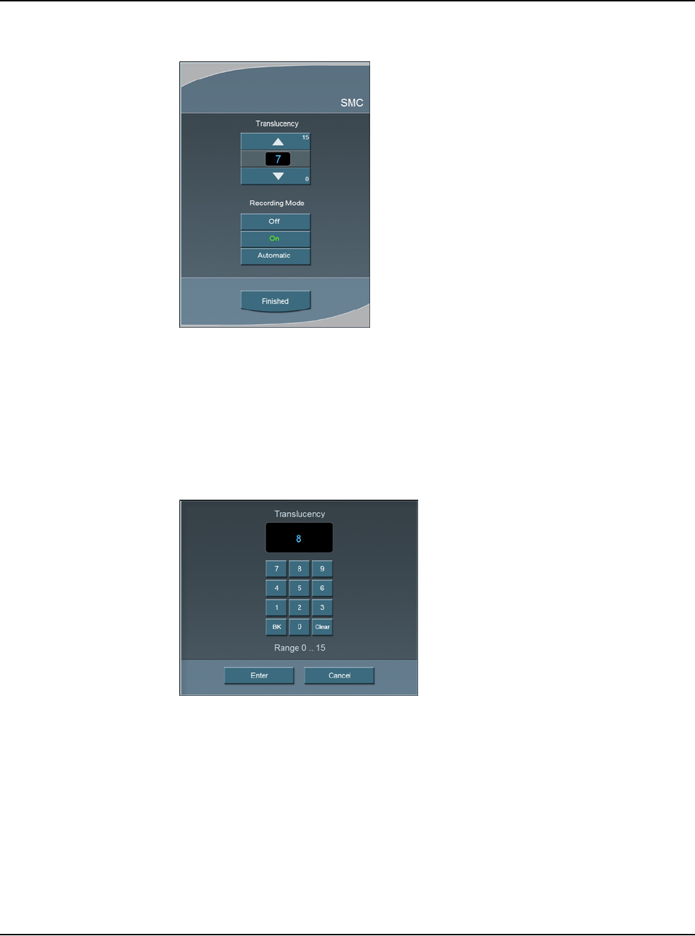
Figure 3.16 – Surgical Media Center Pop-up Window
2. Use the Up and Down arrows to adjust the settings. Translucency is used to
make the overlay (instrument settings) more or less opaque.
Note: Press on the number in the control panel to open a numeric keypad and
enter the required value. Press Enter on the Keypad pop-up window
when you are finished.
Figure 3.17 – Numeric Keypad Pop-up Window
3. Select the Recording Mode. Off, On, or Automatic. If the Recording Mode
is On, the recording continues between cases. Automatic stops recording
between cases.
Note: The Footpedal Switch can be set up to activate the SMC Record function.
4. Press Finished to close the pop-up window.

3 • System Setup
WHITESTAR SIGNATURE™ System Rx Only – Z370147 Rev. C 1108 3-29
Shutdown Sequence
– Anterior Segment
Surgery
The following is a general overview of the steps to be taken to shut the System
down after surgery:
1. Select End Case.
2. Select Shutdown. At the prompt, select Yes.
3. Wait for shutdown sequence to complete.
4. Turn the system Off at the back of the console.
5. Remove the power cord from the power outlet.
6. Wrap the excess power cord neatly around the cord wrap on the back of the
console.
7. Place the footpedal in the storage area on the console.
8. Place the Wireless Remote Control on top of the console to charge.
9. Refer to Chapter 9, “Care and Cleaning”, Cleaning Procedures for additional
information.

4 • Equipment Operation
WHITESTAR SIGNATURE™ System Rx Only – Z370147 Rev. C 1108 4-2
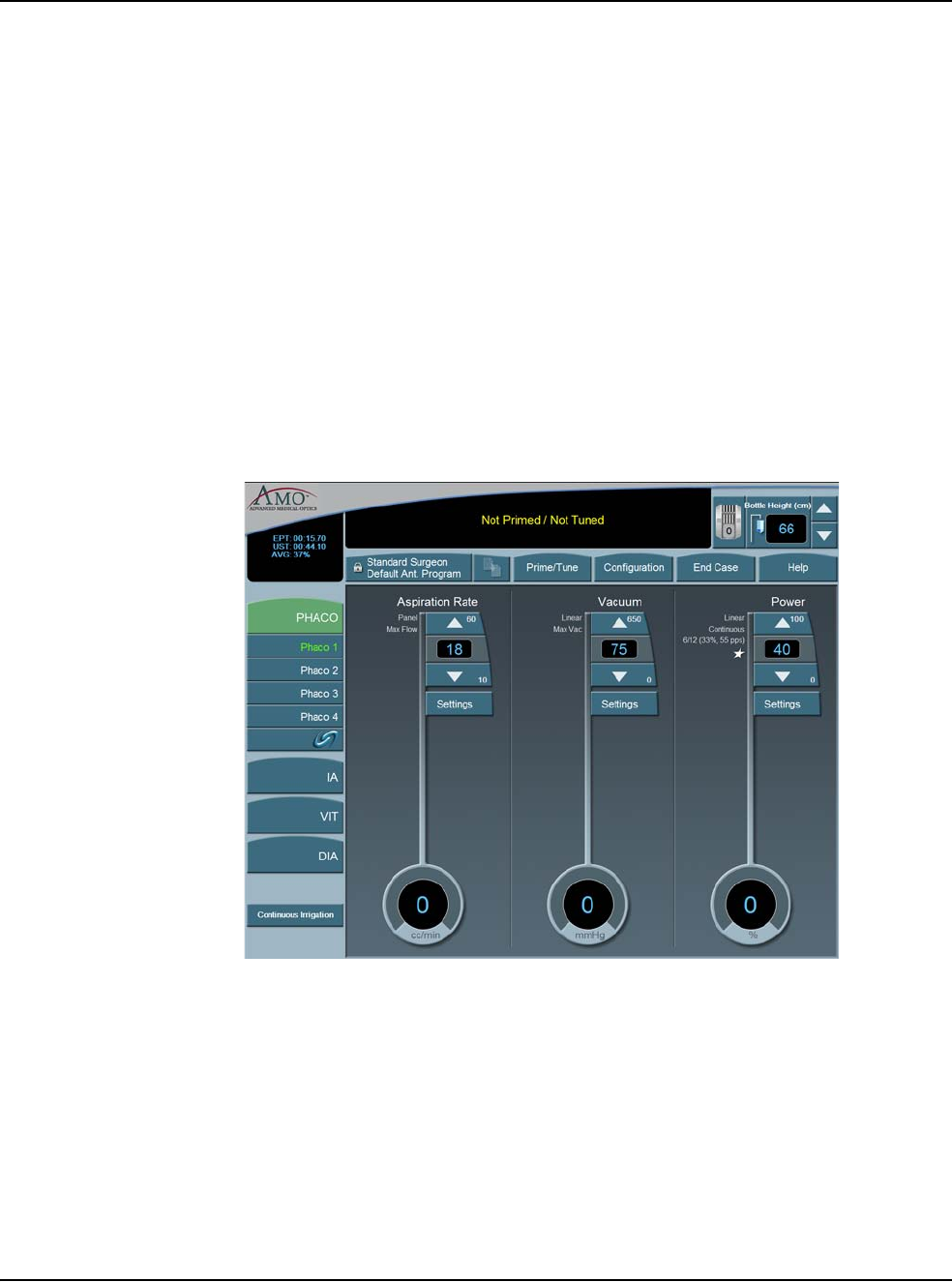
Display Screens and
Controls The touch screen is designed to give you visual indication of the status of the
control systems at all times. When a mode (DIA, PHACO, IA, or VIT) is selected,
the current settings are shown on the screen. As adjustments to settings are made,
the screen shows the changes. The screens and controls are shown below.
Each Anterior segment surgery mode and submode has their own distinct screen
setup:
• Irrigation/Aspiration
• Phaco without OCCLUSION MODE™
• Phaco with OCCLUSION MODE™ and/or CASE (FUSION™ MODE)
• Phaco with Ellips™ technology
• Vitrectomy
• Diathermy
Figure 4.1 – PHACO Screen
Additionally, there are screens or sub-screens for:
•Prime/Tune
• End Case
•Program
• Sounds
•Footpedal
• Database
• Diagnostics
4 • Equipment Operation
WHITESTAR SIGNATURE™ System Rx Only – Z370147 Rev. C 1108 4-3
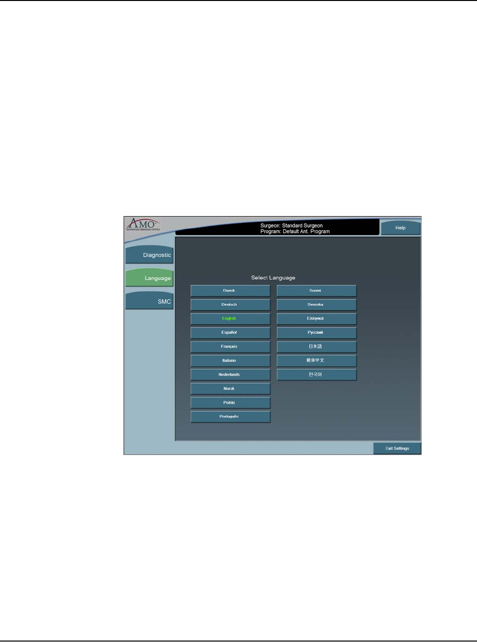
Language Selection The WHITESTAR SIGNATURE™ System features a 17-language user interface.
Before you proceed, select one of the languages for your touch screen and controls.
(English is the default language).
1. To access the Select Language screen, from the main screen, select:
• Configuration
• System Configuration
•Language
2. Select the desired language from the listing.
3. Press Yes at the confirmation pop-up. The screen automatically changes to the
selected language.
4. Press Exit Settings to proceed with the selected language.
Figure 4.2 – Language Screen
Note: On any screen, if you press the screen about 25 times, the System changes
to the default language (English).You must press the same spot on the
screen.
4 • Equipment Operation
WHITESTAR SIGNATURE™ System Rx Only – Z370147 Rev. C 1108 4-4
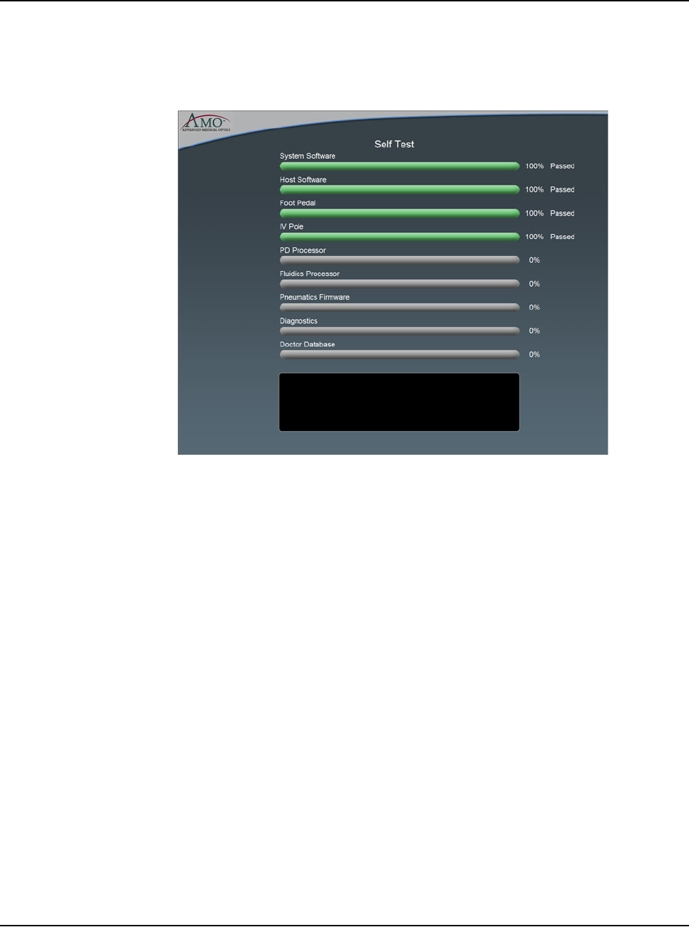
Startup After you have turned on the WHITESTAR SIGNATURE™ System, the system
performs a series of Self Tests.
Figure 4.3 – Self Test
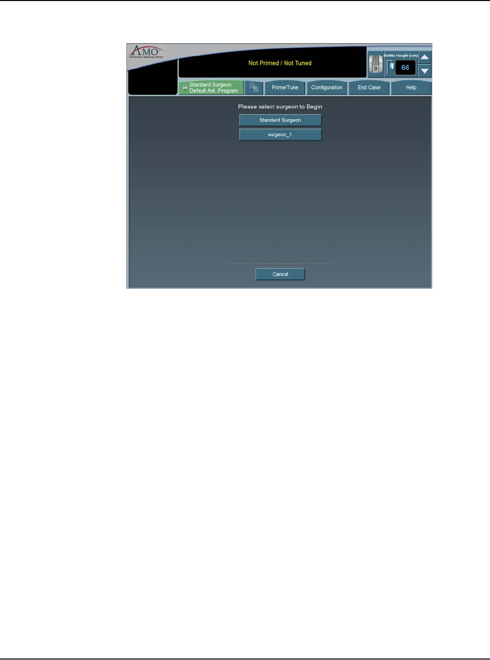
After start up, the screen shows the available Surgeons and Programs that can be
selected.
You can now select a Surgeon and a Program. A Program (or Surgeon Name) is a
set of pre-established operating settings for each operating mode. The
WHITESTAR SIGNATURE™ System allows you program up to a maximum of
50 Surgeon names, and 20 customized surgeon setups (programs) for each surgeon.
4 • Equipment Operation
WHITESTAR SIGNATURE™ System Rx Only – Z370147 Rev. C 1108 4-5
Figure 4.4 – Select Surgeon Screen
If Standard Surgeon is the only surgeon set up, this screen is not shown, and the
System proceeds immediately to the tubing cassette installation screen.
From the Main Menu you can:
• Select a Surgeon/Program and begin surgery based on the values of that
program
•Enter the Settings (Configuration) page, where you can edit, add, or delete
programs and setup operating parameters
•Enter the End Case screen (Refer to Chapter 5, Anterior Segment surgery
Operating Modes, End Case.)
4 • Equipment Operation
WHITESTAR SIGNATURE™ System Rx Only – Z370147 Rev. C 1108 4-6
Select Program and
Install the
FUSION™ Tubing
Cassette
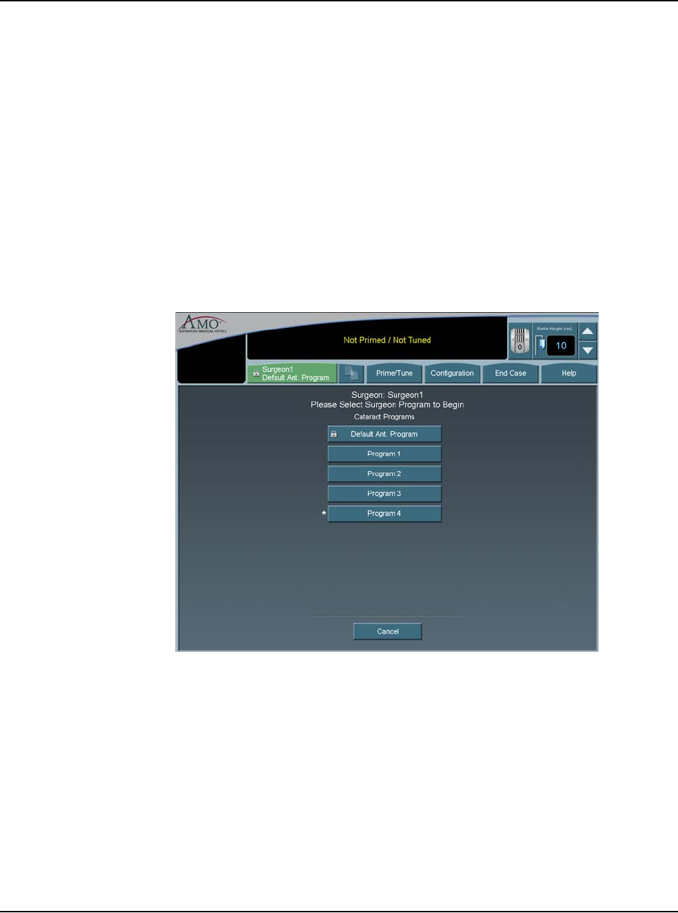
After you select a surgeon, you must select a program from the surgeon's available
programs. If this is the first time the system has been used, AMO Default Program
is the only program that appears on the screen. The first program you create uses
the AMO Default Program settings as a starting point. You can modify the
settings and Save As a specific program or surgeon name. The system does not let
you overwrite the AMO Default Program when you press SAVE.
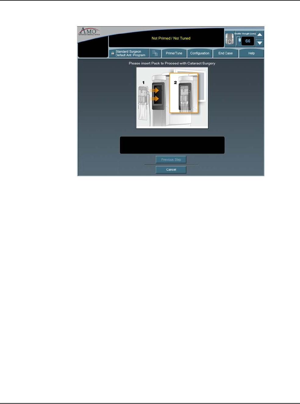
If a surgeon only has one program set up, this screen is not shown, and the System
proceeds immediately to the tubing cassette installation screen for the type of
program that is set up for that surgeon. The System automatically recognizes the
type of tubing casette that is installed.
Note: An asterisk next to a program name indicates that the surgeon as selected
that program as their default program.
Figure 4.5 – Select Program Screen
4 • Equipment Operation
WHITESTAR SIGNATURE™ System Rx Only – Z370147 Rev. C 1108 4-7
Figure 4.6 – Install Cassette Screen
Prime/Tune Prime/Tune is required before surgery is performed to fill the IA tubing with fluid,
perform a vacuum check and to test and characterize the phaco handpiece. You
must Prime and Tune:
• before each procedure
• anytime the handpiece is reconnected
• after you have inserted or replaced a tubing cassette
Continuous Irrigation can be selected to allow fluid to free flow from the bottle in
order to collect fluid.
Note: Before you Prime and Tune, the Cup Fill feature can be used to fill cups. Use
the Up and Down arrows to set the amount needed, either 30, 60 or 90 cc, to fill the
cup and then press Start. The Cup Fill stops when the selected amount is dispensed
or Stop is pressed. You can still use Continuous Irrigation to fill cups.
IA Prime is designed for a procedure that does not require a phaco handpiece. Tune
is designed for a quick tune of the phaco handpiece with an IA tubing set. Tune can
be used if a phaco tip is replaced during a procedure.
When you Bypass prime the overall fluidics prime sequence is shortened and the
time to prime the WHITESTAR SIGNATURE™ System is reduced. Bypass can
be used if Continuous Irrigation has been used or the I/A tubing was primed. If
the I/A tubing was not properly primed, errors can occur.
To access the Prime/Tune routines, press the Prime/Tune button. The main
console shows the Prime/Tune screen with all prime and tune options.
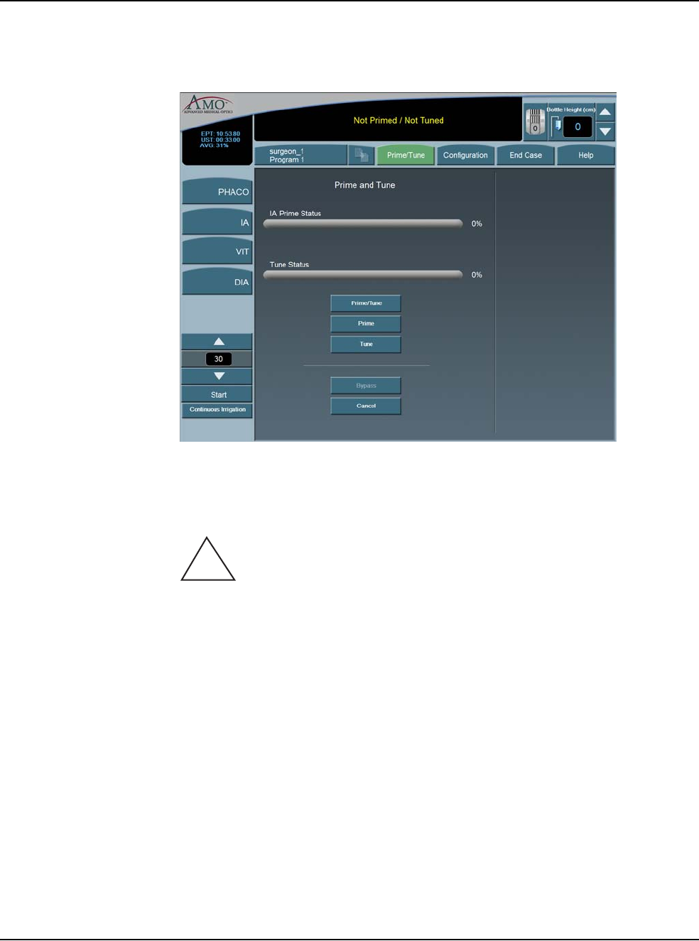
4 • Equipment Operation
WHITESTAR SIGNATURE™ System Rx Only – Z370147 Rev. C 1108 4-8
Note: Prime/Tune is a combination of Tune followed by IA Prime.
Figure 4.7 – Prime and Tune Screen
The WHITESTAR SIGNATURE™ System tracks the successful completion of the
Prime and Tune cycle independently. In the event a retune is required (new tip,
failed tune), only the Tune needs to be selected and run.
CAUTION: THE PHACO HANDPIECE AND VITRECTOMY
CUTTER MUST NEVER BE ACTIVATED WITH THE TIP IN THE AIR.
EXPOSURE OF THE TIP TO AIR DRASTICALLY REDUCES THE
USEFUL LIFE OF THE HANDPIECE. IF POWER IS TO BE
INTRODUCED TO THE PHACO HANDPIECE OR VITRECTOMY
CUTTER, THE TIP MUST BE IN A TEST CHAMBER FILLED WITH
BALANCED SALT SOLUTION, IN A CONTAINER OF BALANCED SALT
SOLUTION OR IN THE PATIENT’S EYE.
Suggestions for Priming the Handpieces
Always fill the test chamber completely prior to running the Prime/Tune Cycle.
Do not lay the handpiece and the empty test chamber down and have the system fill
the test chamber. This allows air to collect in the test chamber and can produce an
error.
To collect the balanced salt solution:
1. Use the test chamber, a medicine cup, or similar container.
!

4 • Equipment Operation
WHITESTAR SIGNATURE™ System Rx Only – Z370147 Rev. C 1108 4-9
2. Use the Up and Down arrows to increase or decrease the amount of the fluid
needed.
3. Press Start to turn on Cup Fill.
4. Use Stop to turn off Cup Fill before the requested amount of fluid is dispensed.
5. Perform a full Phaco Prime/Tune.
The Prime/Tune screen indicates the progress of the priming process.
1. Use the Cup Fill feature to fill the test chamber with fluid and to eliminate all
air. If the test chamber is attached to the handpiece, remove the test chamber
before you start the Cup Fill process.
2. Place the test chamber over the handpiece tip and the sleeve hub.
3. Press the Prime/Tune button, this starts the Prime and Tune sequences.
• To perform a Prime only, press the Prime button.
• To perform a Tune only, press the Tune button.
4. Make sure the movement of the IV pole is not blocked by low ceilings.
5. Watch the fluid fill the drip chamber. The fluid moves toward the handpiece
and fills the test chamber.
6. The touch screen indicates the progress of the Prime and Tune process.
7. As the tubing lines are filled, the system software performs functional checks.
The checks include:
• Monitoring for the presence of irrigation flow (bottle height)
• Leaks (via vacuum rise checks)
8. If the phaco handpiece is plugged in and Prime/Tune or Tune was selected,
the system automatically includes a handpiece tuning test concurrently with the
prime cycle.
• At the end of the priming sequence, the WHITESTAR SIGNATURE™
System makes an audible sound to indicate that Prime process is complete.
• At the end of the phaco tuning test, the WHITESTAR SIGNATURE™
System makes an audible alert sound to indicate that tune process is
complete.
9. To discontinue Prime or Tune during the process, select Cancel.
10. When Prime and Tune are complete, the system automatically proceeds to the
preprogrammed submode or Phaco 1 operating mode. It is important that you
verify the IA balance prior to operating.
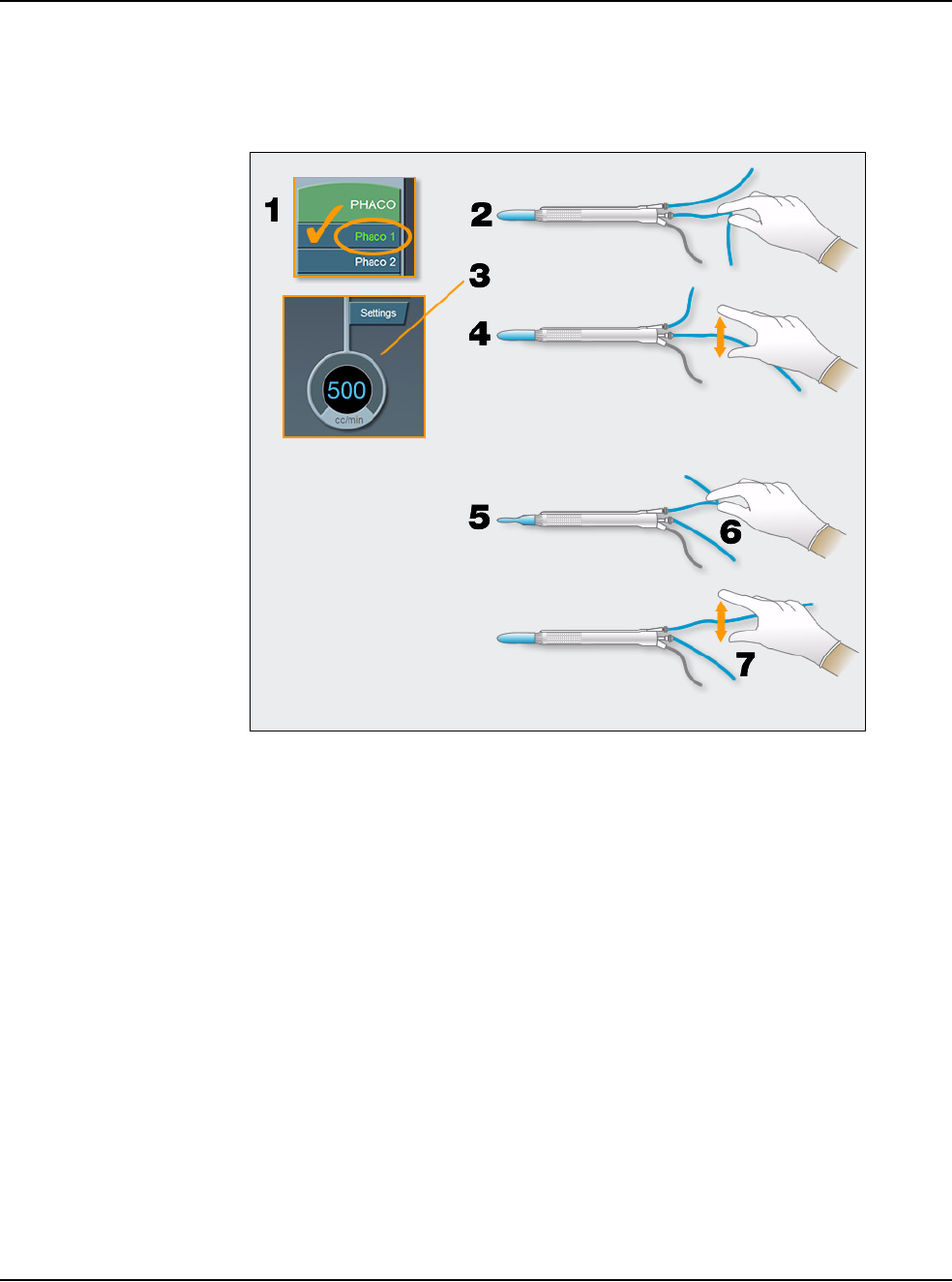
4 • Equipment Operation
WHITESTAR SIGNATURE™ System Rx Only – Z370147 Rev. C 1108 4-10
Verify Irrigation/
Aspiration Balance We strongly recommend verifying that Irrigation/Aspiration is balanced properly
for the settings to be used in surgery.
Figure 4.8 – Irrigation/Aspiration Balance Procedure
To verify Irrigation/Aspiration balance:
1. In PHACO 1 mode, hold the handpiece at approximate patient eye level.
2. Occlude the aspiration line just below the handpiece, while you press and hold
the footpedal in position 2. Make sure the footpedal is connected. (Refer to
Chapter 3, System Setup, Footpedal.)
3. The actual vacuum level should rise to the preset level.
4. Release the aspiration line and watch the test chamber to make sure that the test
chamber does not collapse. A slight shallowing of the test chamber is normal.
5. If the test chamber collapses, raise the IV bottle height or lower the vacuum
setting.
6. Pinch the irrigation tubing at the handpiece and watch for the test chamber to
collapse.
7. Release the irrigation line and the test chamber should fill.
8. Press Reset in the upper left corner of the screen to open the Reset Timers
pop-up window. Press Yes to reset the timers. You are now ready to begin
surgery.
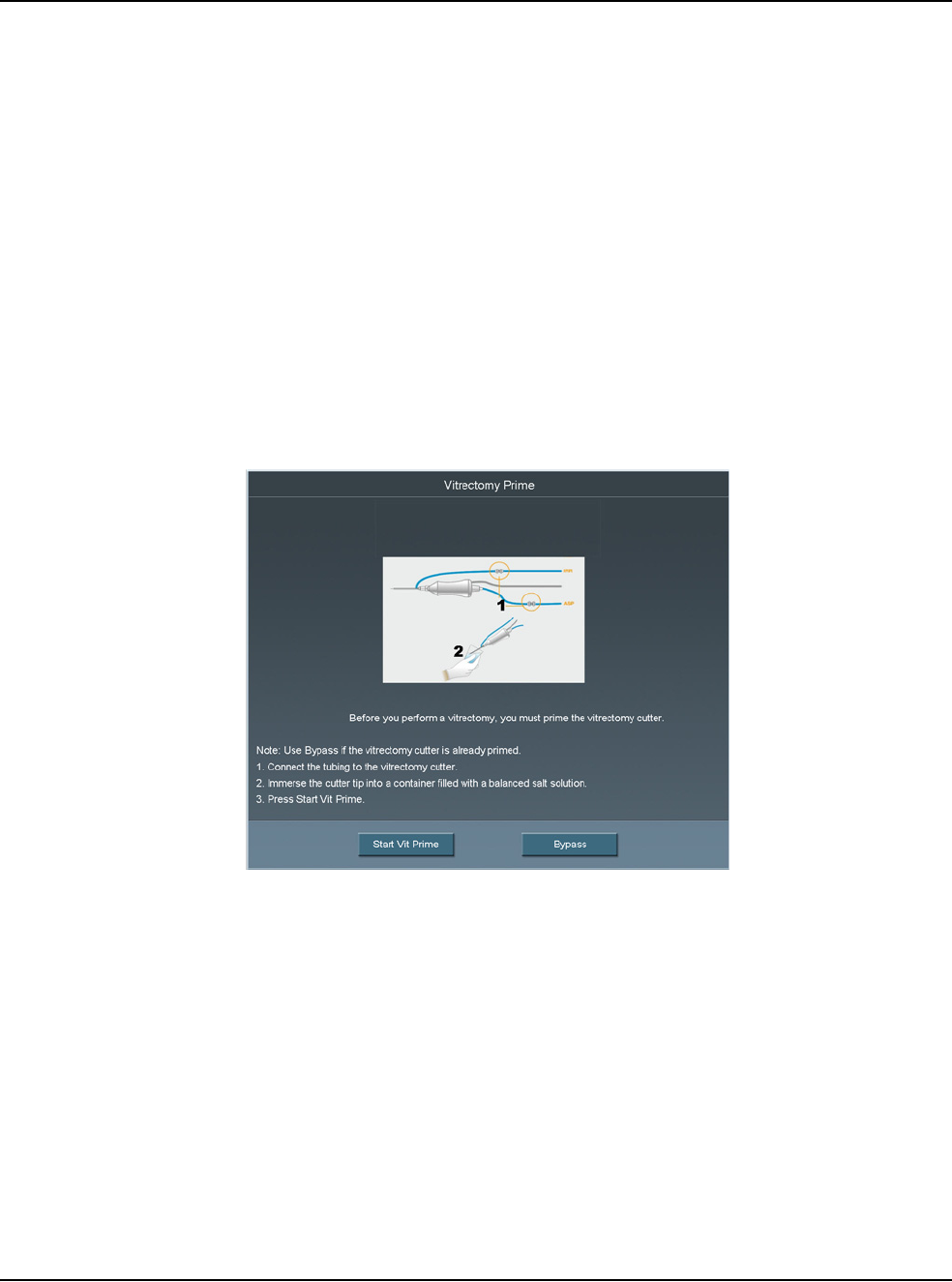
4 • Equipment Operation
WHITESTAR SIGNATURE™ System Rx Only – Z370147 Rev. C 1108 4-11
Priming for
Vitrectomy Before you perform vitrectomy, we recommend you prime the handpiece in order
to reduce the chance of errors. Each time you select vitrectomy mode you are
prompted to prime the vitrectomy handpiece. If you do not need to prime, press
Bypass.
To prime the handpiece:
1. Attach the irrigation and aspiration cassette pack tubing together.
2. Press Prime on the Prime/Tune screen.
3. Press the VIT button to enter VIT mode.
4. Follow the instructions on the screen.
5. Press Start Vit Prime. The screen closes automatically when the handpiece is
primed.
Note: If you must perform vitrectomy in the middle of phaco surgery, perform
steps 3 through 5.
Figure 4.9 – Vitrectomy Prime Procedure
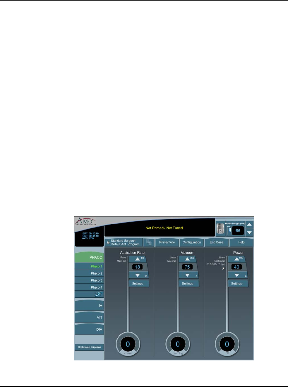
4 • Equipment Operation
WHITESTAR SIGNATURE™ System Rx Only – Z370147 Rev. C 1108 4-12
Selecting and
Changing Mode
Parameters
The system's graphical user interface (GUI) and touch screen is designed for
ease-of-use, consistent application and maximum informational display during all
operating modes.
Your interface with the system requires only three basic steps, which apply to all of
the selections, settings and operations. Once this basic organization is understood,
you can move quickly and easily through all of the system functions and
operations.
The touch screen is organized into panels. The top panel shows current status,
configuration options, the bottle height, and the footpedal icon. The left-side
column lists the operating modes and submodes. The main panel that dominates the
screen shows current operating levels for aspiration, vacuum and power.
• To switch operating modes or submodes, press a button in the left panel. The
control panels in the main panel show the operating levels for that mode.
• To make basic changes to the settings, press the Up and Down arrows to increase
or decrease a value.
Note: Press on the number in the Settings control panel to open a numeric keypad
and enter the required value. Refer to Figure 3.17 Numeric Keypad Pop-up
Window. Press Enter to close the Keypad window.
• To change other control panel settings, such as Panel or Linear power, press the
Settings button on that control panel. A Settings window opens, and you can
make your selections.
Figure 4.10 – PHACO Mode Screen
• To make overall changes to a program, press Configuration on the top panel.
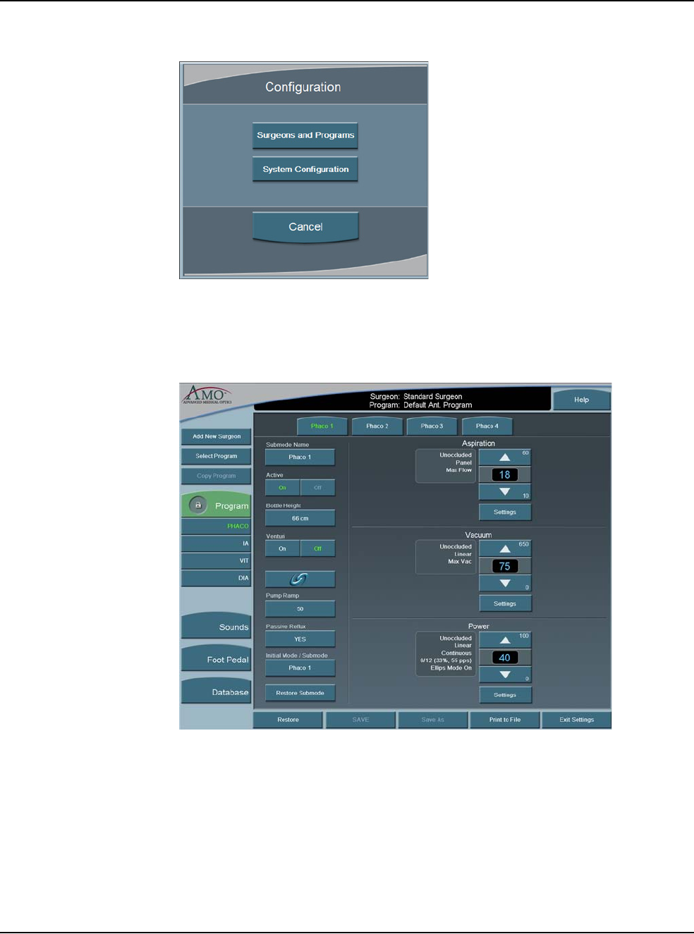
4 • Equipment Operation
WHITESTAR SIGNATURE™ System Rx Only – Z370147 Rev. C 1108 4-13
Figure 4.11 – Configuration Pop-up Window
• Press Surgeons and Programs to access surgeon names and their associated
program setups.
Figure 4.12 – PHACO Submode Configuration Screen

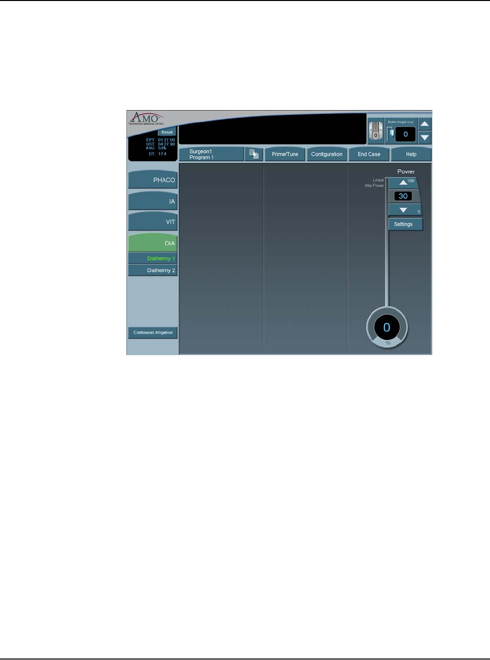
5 • Anterior Segment Surgery Operating Modes
WHITESTAR SIGNATURE™ System Rx Only – Z370147 Rev. C 1108 5-2
Operating Mode
Descriptions Diathermy
While the system is priming, you can select the Diathermy (DIA) mode (a function
which does not require irrigation and aspiration flow) and perform Diathermy
procedures. This process is referred to as a Diathermy during Prime.
Figure 5.1 – Diathermy Mode Screen
If Diathermy is selected during Prime, the screen indicates the Prime/Tune status
and any messages associated with the prime and/or tune.
The WHITESTAR SIGNATURE™ System provides power for bipolar
coagulation or diathermy. The amount of diathermy power is shown on the
Diathermy screen. If Panel power is selected, you can increase or decrease power
by pressing the Up or Down arrows on the Power control panel. If the Linear mode
is selected, the power is controlled with the footpedal up to the maximum preset
value.
Note: Press on the number in the Settings control panel to open a numeric keypad
and enter the required value. Refer to Figure 3.17 Numeric Keypad Pop-up
Window. Press Enter when you are finished.
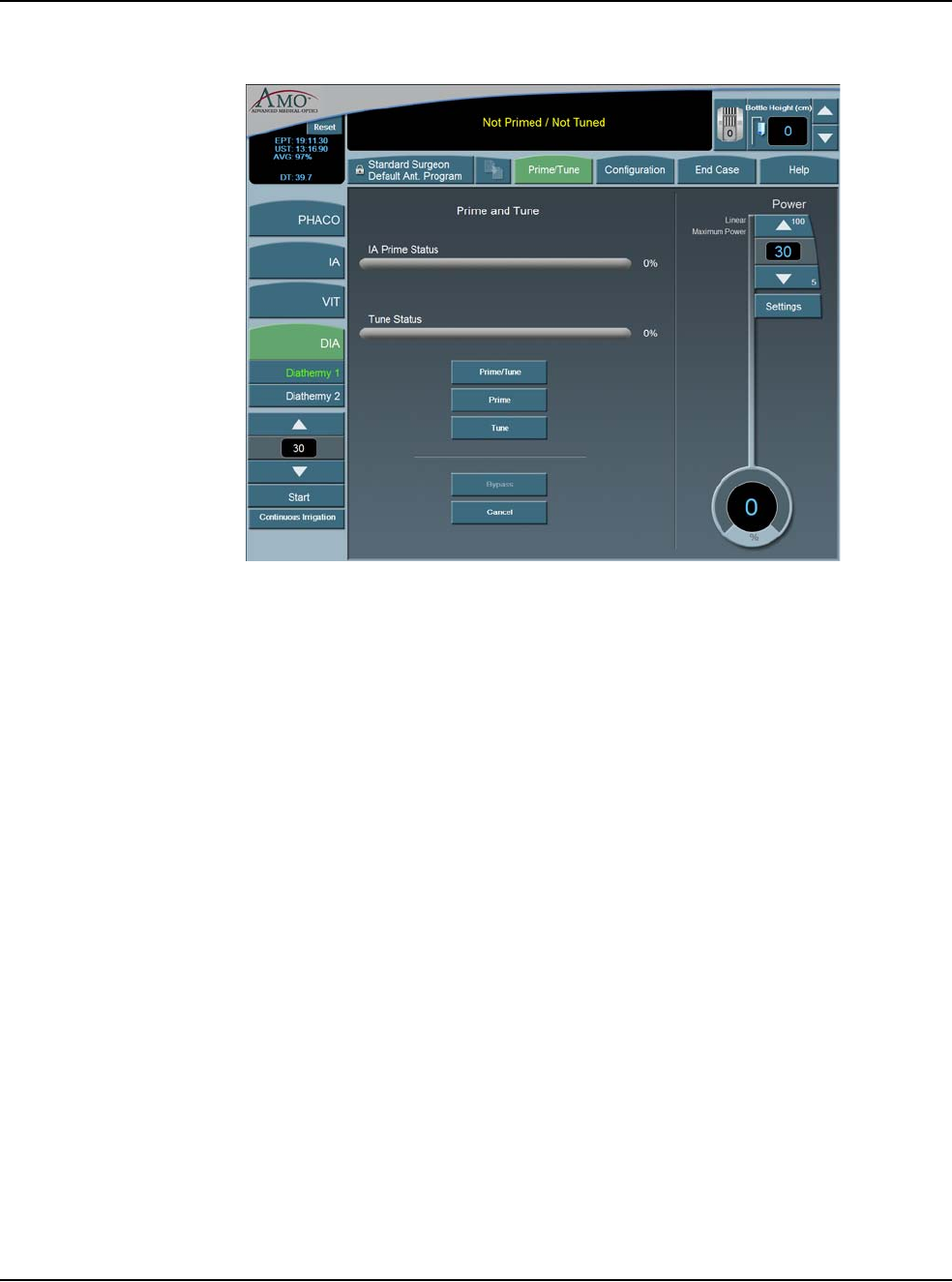
5 • Anterior Segment Surgery Operating Modes
WHITESTAR SIGNATURE™ System Rx Only – Z370147 Rev. C 1108 5-3
Figure 5.2 – Prime/Tune in Diathermy Mode
Using Diathermy
To begin Diathermy:
1. On the left panel press DIA.
2. Press the desired DIA submode button (DIA 1 is selected by default).
The elapsed DIA time is displayed in the upper left corner as “DT”.
In the main panel, you can increase or decrease the power by pressing the
diathermy Power Up or Down arrows. If Linear power is selected, you can use the
footpedal to increase or decrease the power up to the maximum preset value.
To change the power delivery, press Settings. The Settings window opens. Set the
power delivery to Panel, Linear or Burst. Linear delivery is the default.
•Panel – Diathermy power is delivered consistently at the power level (%)
selected and indicated on the screen as Panel Maximum Power.
•Linear – Diathermy power is delivered from 5% to the maximum selected value
(Maximum Power) as the footpedal is pressed.
•Burst – Diathermy is delivered as a single 150 ms pulse, at the selected power,
as the footpedal is pressed.

5 • Anterior Segment Surgery Operating Modes
WHITESTAR SIGNATURE™ System Rx Only – Z370147 Rev. C 1108 5-4
Figure 5.3 – Diathermy Power Submode
To set the submode parameters:
1. Make the desired settings to the DIA 1 values
2. Press the DIA 2 button to set the parameter values.
3. Change the parameter values for DIA 2.
4. After the submode (Program submode DIA 1, DIA 2) parameters are set, you
can press another mode button in the left panel to program PHACO, IA, or
VIT modes.
5. To access the SAVE buttons and save the submode settings, press End Case in
the top panel if no other changes are needed and save the settings.
Irrigation/Aspiration
Aspiration flow is necessary to remove the emulsified cataract material from the
eye. An irrigation supply is necessary to replace fluid removed by aspiration of
cortical material and fluid lost to leakage from the incision.
This fluid balance maintains the anterior chamber during surgery. Irrigation is
controlled by gravity.
The flow rate of irrigation solution through the irrigation sleeve on the phaco tip is
determined by the height of the drip chamber (head pressure). The drip chamber
hangs from the bottle on the Programmable IV Pole. AMO recommends that at the
start of a procedure, the irrigation solution level in the drip chamber be located
approximately 65–70 cm above the patient's eye level. To increase irrigation
pressure, the IV bottle is raised. To decrease pressure, the bottle is lowered.
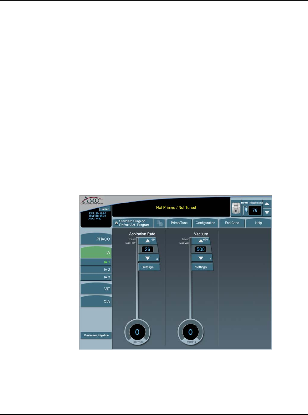
5 • Anterior Segment Surgery Operating Modes
WHITESTAR SIGNATURE™ System Rx Only – Z370147 Rev. C 1108 5-5
The irrigation tubing runs through the tubing cassette and irrigation is controlled by
the footpedal. When the footpedal is pressed, the pinch valve is opened and the
irrigation fluid flows. Irrigation runs in footpedal Positions 1, 2 and 3.
To program IA submodes:
1. On the left panel, press IA.
2. Select the desired IA submode. IA 1 is selected by default.
3. Press the Up or Down arrows in the control panels on the main panel to
increase or decrease Aspiration Rate or Vacuum.
Note: If the Venturi pump is On, only the Vacuum Settings are shown. To turn
the Venturi pump setting on, use the IA Submode Configuration screen.
4. Press the Settings button in the control panels on the main panel to change
Aspiration Mode or Vacuum Mode,
5. Press Finished to close the Settings window.
6. After all the submodes are programmed, select another mode.
7. If no other changes are needed press End Case to access the SAVE buttons and
save the settings.
Figure 5.4 – Irrigation/Aspiration Mode
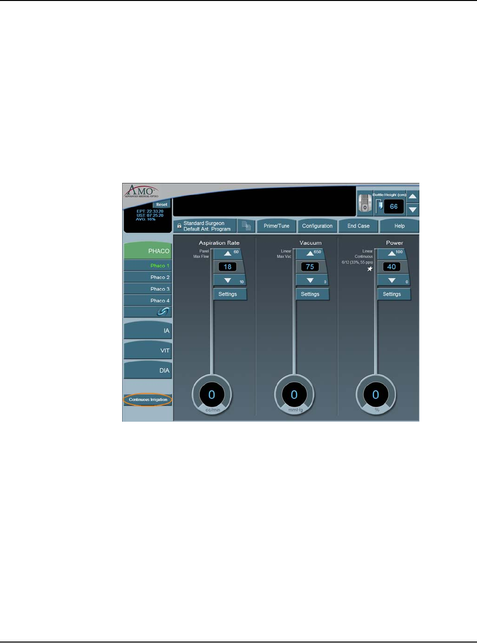
5 • Anterior Segment Surgery Operating Modes
WHITESTAR SIGNATURE™ System Rx Only – Z370147 Rev. C 1108 5-6
Continuous Irrigation
Continuous Irrigation is designed for collection of balanced salt solution for use
during the case. This function opens the irrigation valve for fluid collection
independent of the footpedal or prime cycle.
To activate Continuous Irrigation:
1. On the side panel, press the Continuous Irrigation button. This opens the
valve and starts the flow of irrigation fluid.
2. Press Continuous Irrigation again to deactivate the continuous irrigation.
Figure 5.5 – Continuous Irrigation
Phacoemulsification
The purpose of phacoemulsification or PHACO is to emulsify the lens material.
The phacoemulsification (phaco) handpiece provides ultrasonic energy, irrigation
and aspiration simultaneously so that the lens material is extracted as it is
emulsified. The phacoemulsification handpiece has a hollow needle that vibrates
longitudinally at an ultrasonic frequency or a blend of longitudinal and transversal,
if using the Ellips™. The rapid movement of the needle and the resulting
cavitational energy disintegrates the cataract on contact. The debris is removed by
suction through the hollow needle (aspiration). The resulting loss in volume of the
anterior chamber is compensated by incoming balanced salt solution (irrigation).
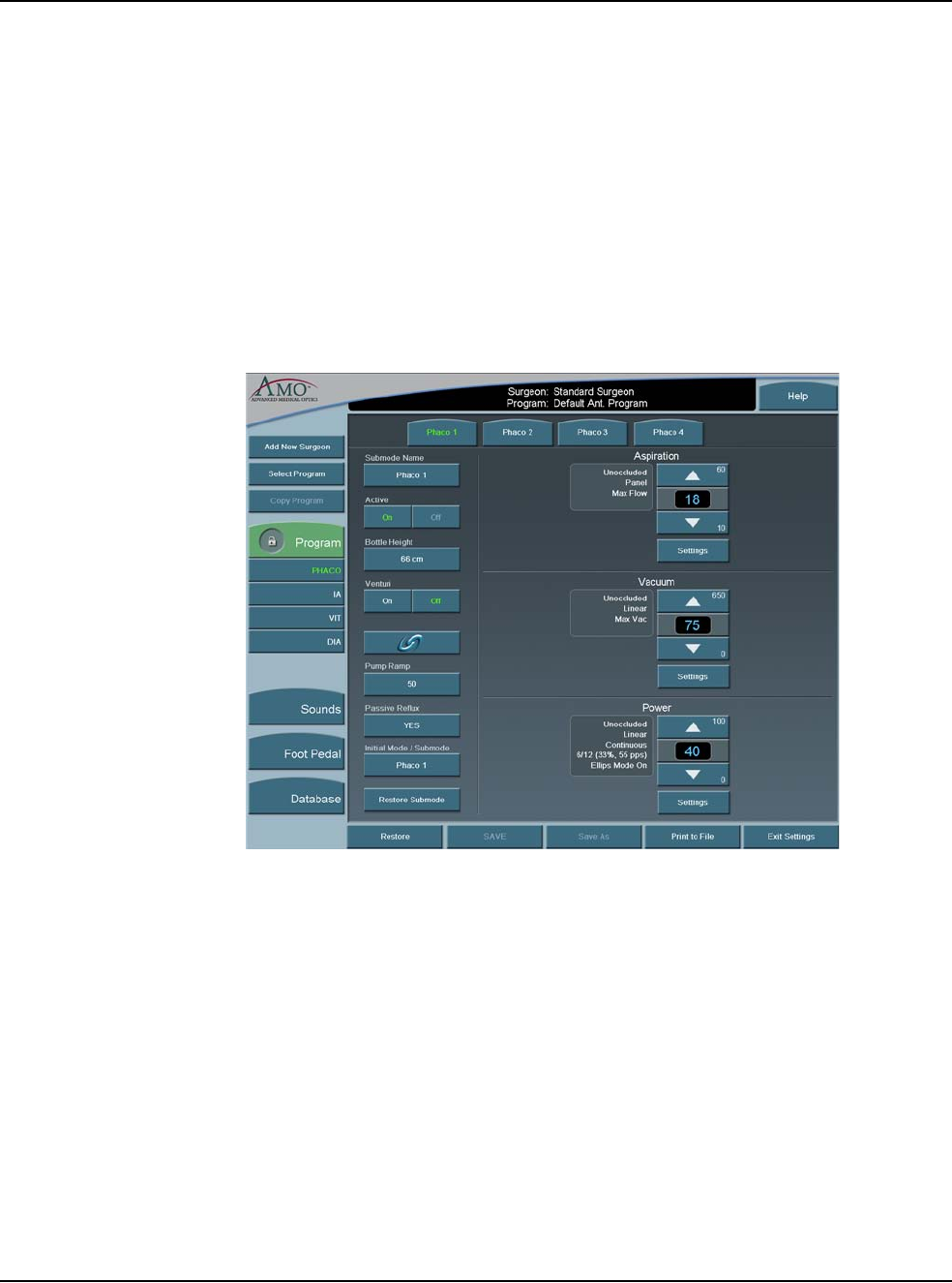
5 • Anterior Segment Surgery Operating Modes
WHITESTAR SIGNATURE™ System Rx Only – Z370147 Rev. C 1108 5-7
PHACO Submodes
There are four PHACO submodes. Within each submode, there are programmable
parameters for Unoccluded Phaco, and Occluded Phaco, and CASE settings.
Phaco Power is a combination of stroke length, frequency and handpiece
efficiency. A preset power setting of 30% using linear control allows you the
ultimate control during phaco. Adjustments to phaco power depend on factors that
include nuclear density, your preferences and your experience.
Phacoemulsification mode lets you set four submodes with different settings. You
can adjust the individual parameters of each submode.
Figure 5.6 – PHACO Submodes
For each PHACO submode, you can change the following settings:
• Aspiration Rate
•Vacuum
•Power
Before phacoemulsification, you must complete the steps to verify the Irrigation
and Aspiration balance, as recommended in the Irrigation/Aspiration section in this
chapter.
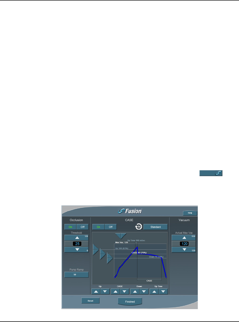
5 • Anterior Segment Surgery Operating Modes
WHITESTAR SIGNATURE™ System Rx Only – Z370147 Rev. C 1108 5-8
Using PHACO
1. Press PHACO.
2. Press Phaco 1, Phaco 2, Phaco 3, or Phaco 4 to select the submode. The main
panel shows all of the settings for Aspiration Rate, Vacuum and Power. Each
submode has different default settings.
3. Press the footpedal to activate phacoemulsification. The Aspiration Rate,
Vacuum and Power control panels indicate the associated levels throughout the
procedure. The Footpedal icon in the upper right corner of the screen shows the
position of the footpedal.
How to Program PHACO
1. Press the PHACO button.
2. Press the desired submode button. Phaco 1 is selected by default.
Note: You can set your Initial Mode/Submode on the Phaco Configuration screen.
The Initial Mode/Submode is then your default setting. (Refer to Program
Configuration, in this chapter.)
3. In the control panels in the main panel, click the Up or Down arrows to
increase or decrease Aspiration Rate, Vacuum, or Power.
Note: If the Venturi pump is On, only the Vacuum and Power Settings are shown.
CASE is not accessible when the Venturi pump is On.
4. Repeat for each submode you want to program.
5. If OCCLUSION MODE™ Phaco or CASE is desired, press in the
left column to activate the FUSION™ Mode screen. When OCCLUSION
MODE™ Phaco is active, the On button is green.
Figure 5.7 – Fusion™ Fluidics Screen
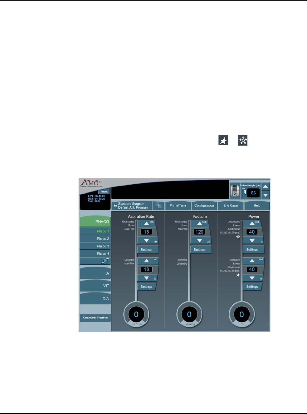
5 • Anterior Segment Surgery Operating Modes
WHITESTAR SIGNATURE™ System Rx Only – Z370147 Rev. C 1108 5-9
If you use CASE or OCCLUSION MODE™ Phaco, you can set different values
for both Occlusion Threshold and Max Vacuum. Refer to Fusion™ Fluidics Phaco
for programming CASE and OCCLUSION MODE™ Phaco modes.
After all four PHACO submodes are programmed; press a mode button to select
another mode.
If no other changes are needed press End Case to access the SAVE buttons and
save the settings.
WHITESTAR® Technology
The WHITESTAR® Technology can be applied in any phaco power delivery
mode. This technology is an advanced phacoemulsification power mode that
delivers finely modulated pulses of energy interrupted by extremely brief cooling
periods. This technology is available in Linear or Panel mode. When the
WHITESTAR® delivery mode is turned on, either or appears on the touch
screen, along with the WHITESTAR® Duty Cycle.
Figure 5.8 – WHITESTAR® Technology
WHITESTAR® Duty Cycles are expressed as Pulse Time On/Pulse Time Off, to
achieve a desired Duty Cycle. For example, the Duty Cycle setting 6/12 means that the
pulse time On is 6 ms, and the pulse time Off is 12 ms, resulting in a 33% duty cycle.
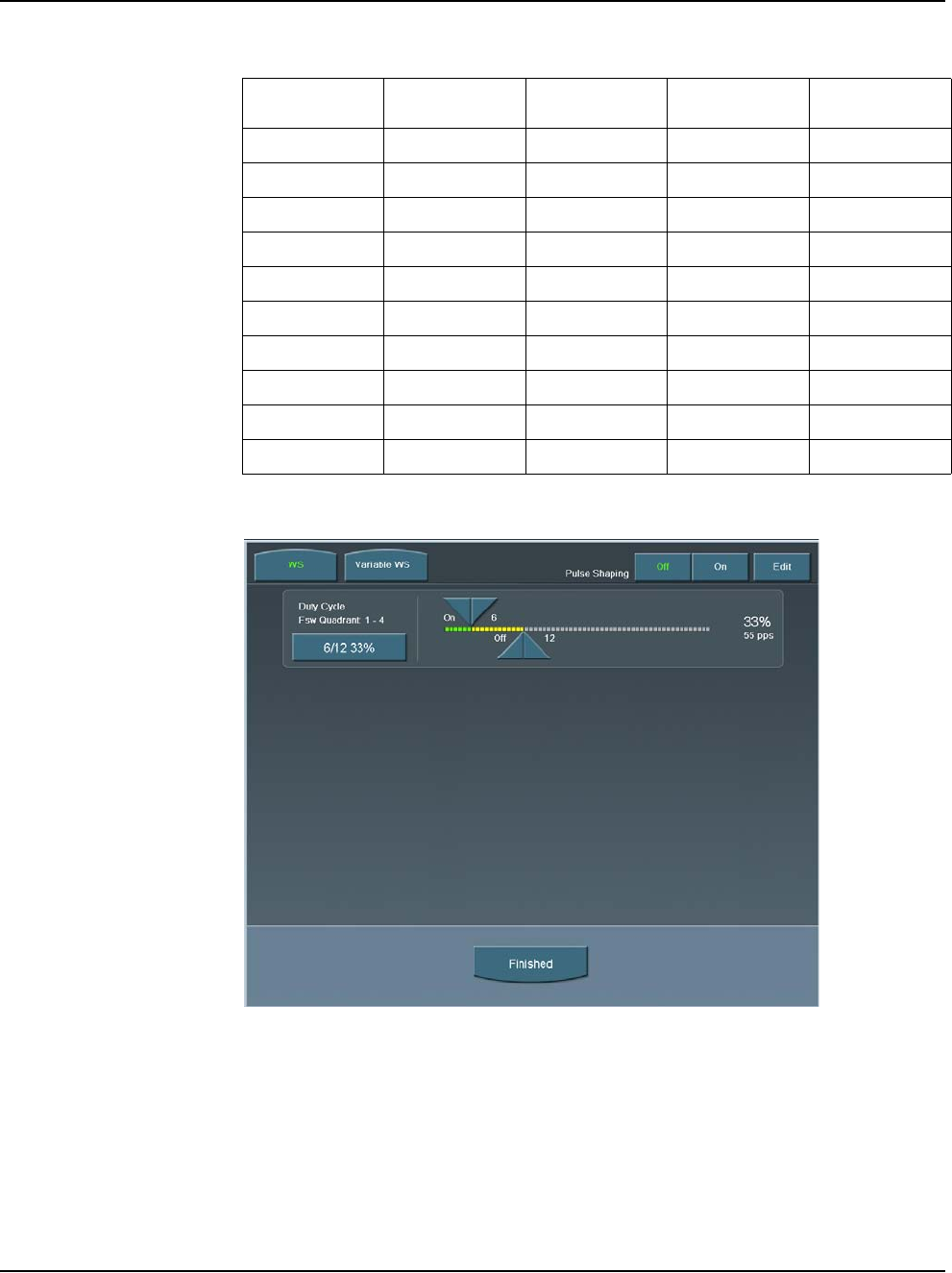
5 • Anterior Segment Surgery Operating Modes
WHITESTAR SIGNATURE™ System Rx Only – Z370147 Rev. C 1108 5-10
Table 5.1 – WHITESTAR® Technology Parameter Settings
Figure 5.9 – Duty Cycle
When the Variable WHITESTAR® Technology is used, different duty cycles are
applied as the footpedal moves through the power delivery zone. The zone is
divided into four equal size quadrants, and a different duty cycle can be applied in
each quadrant.
Setting Pulse On
Time (ms) Pulse Off
Time (ms) Duty Cycle Pulse Rate
(pps)
6/12 6 12 33% 55
4/8 4 8 33% 83
6/4 6 4 60% 100
6/8 6 8 43% 71
8/4 8 4 67% 83
4/24 4 24 14% 35
6/28 6 28 18% 29
6/24 6 24 20% 33
8/24 8 24 25% 31
6/18 6 18 25% 41
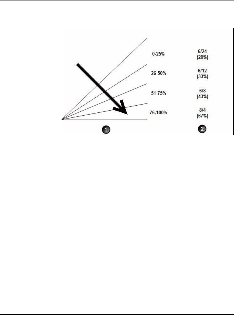
5 • Anterior Segment Surgery Operating Modes
WHITESTAR SIGNATURE™ System Rx Only – Z370147 Rev. C 1108 5-11
Figure 5.10 – Variable WHITESTAR® Technology Footpedal Positions and
Duty Cycles
The WHITESTAR SIGNATURE™ System maintains duty cycles to be used with
Variable WHITESTAR® – Variable WS. Variable WS contains the four duty
cycles that are used in the different quadrants. You can also use the sliding
adjustments to create Custom WHITESTAR® duty cycles for WS.
1. Footpedal Position 3
2. WHITESTAR® Duty Cycle
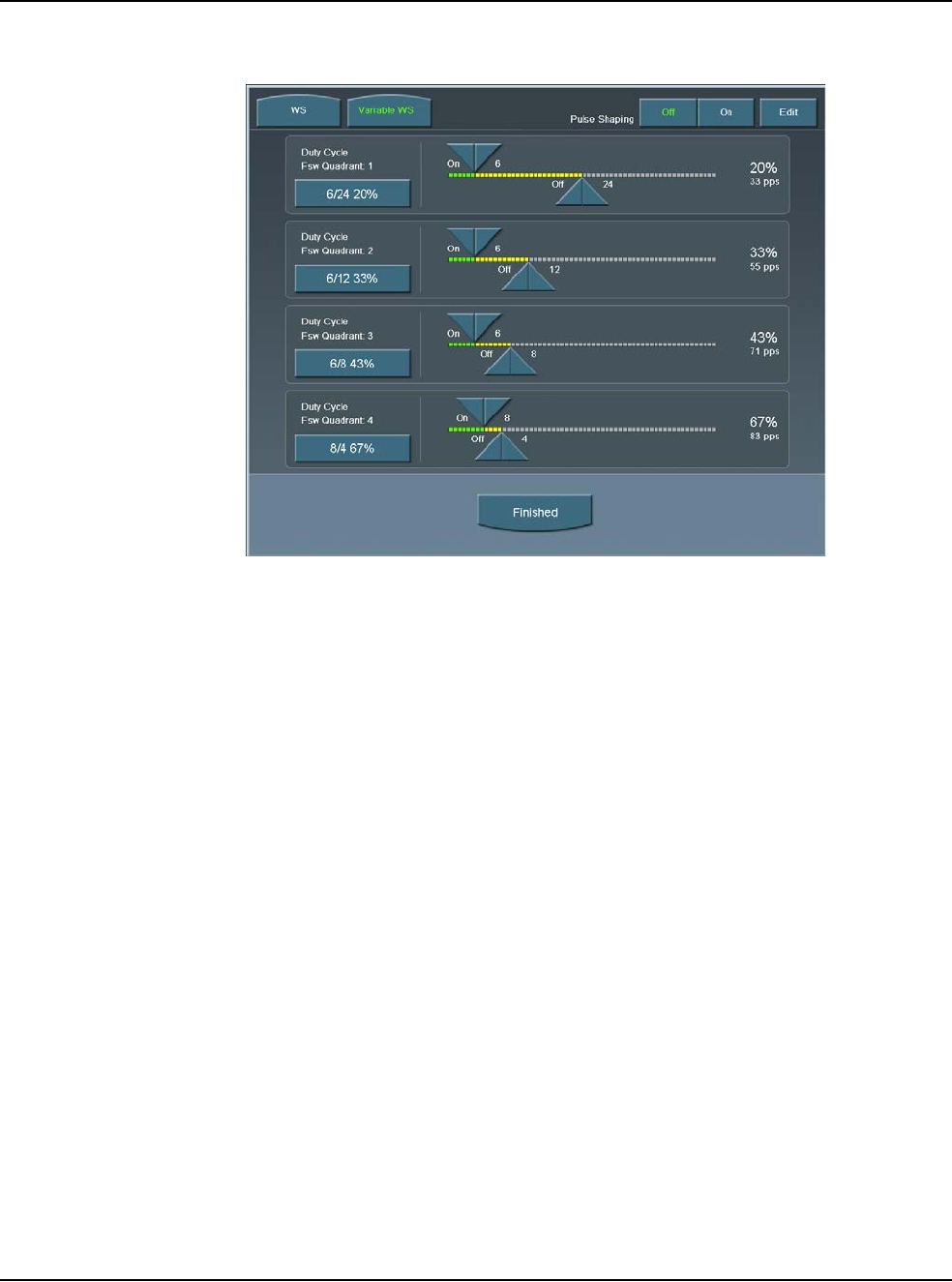
5 • Anterior Segment Surgery Operating Modes
WHITESTAR SIGNATURE™ System Rx Only – Z370147 Rev. C 1108 5-12
Figure 5.11 – Duty Cycles for Variable WS
WHITESTAR® ICE Technology Pulse Shaping
The WHITESTAR® ICE Technology was the next micro-pulse advance in
phacoemulsification technology, which combined modulated ultrasonic power
(pulse shaping) with vacuum control through the application of the Chamber
Stabilization Environment (CASE).
This pulse shaping technology modified the standard “square” wave pulse, by
increasing the amplitude of the first millisecond of the On Time “kick”, and then
setting the remaining part of the On Time to the standard power setting. This is
repeated for each On Time period, resulting in increased control and efficiency in
phacoemulsification.
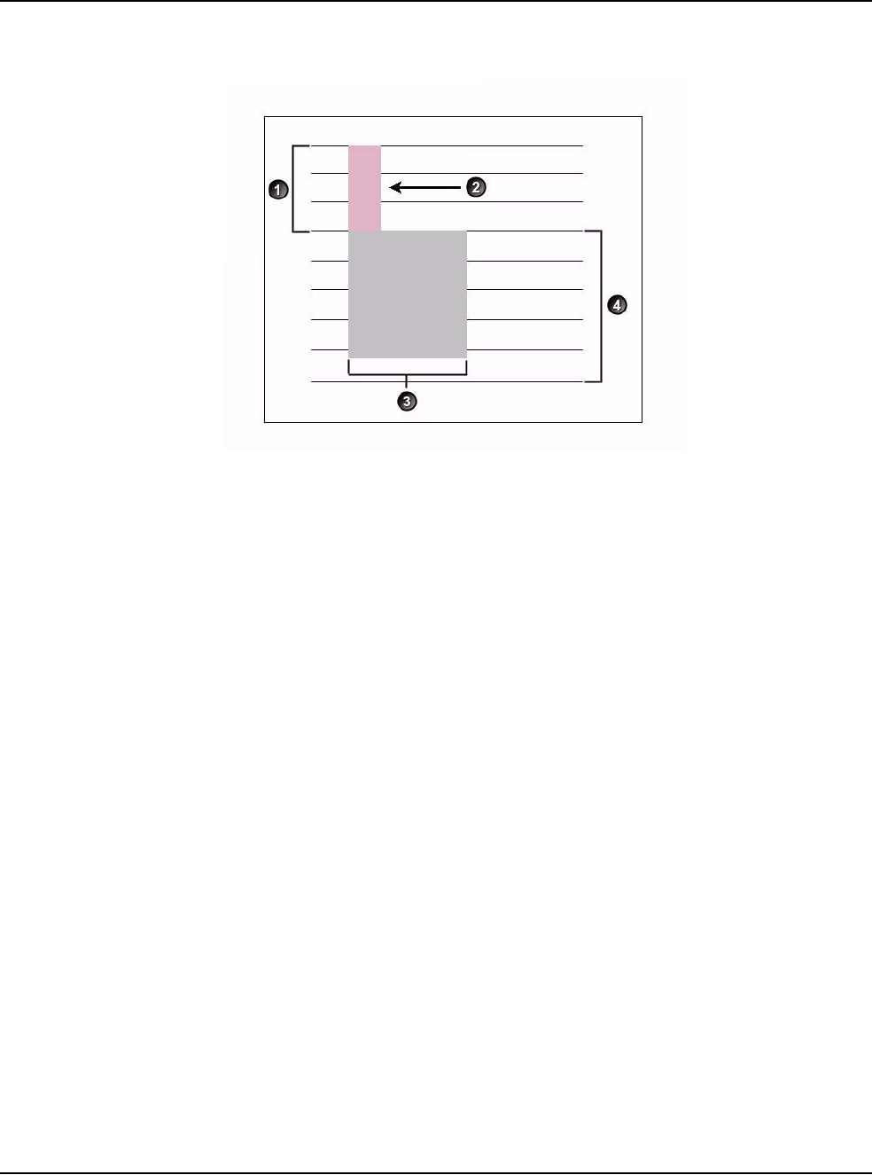
5 • Anterior Segment Surgery Operating Modes
WHITESTAR SIGNATURE™ System Rx Only – Z370147 Rev. C 1108 5-13
Figure 5.12 – WHITESTAR® ICE Technology Pulse Shaping
To access the WHITESTAR® ICE Technology settings:
1. Press the Power Settings button.
2. Press the WHITESTAR mode button.
3. Press On for Pulse Shaping.
4. Press Edit to access the Pulse Shaping parameter settings.
5. Press Finished to close the screen. Continue to press Finished to return to the
main screen.
1. Kick Amplitude 3. Burst Width
2. 1 Millisecond Kick 4. Phaco Power Level
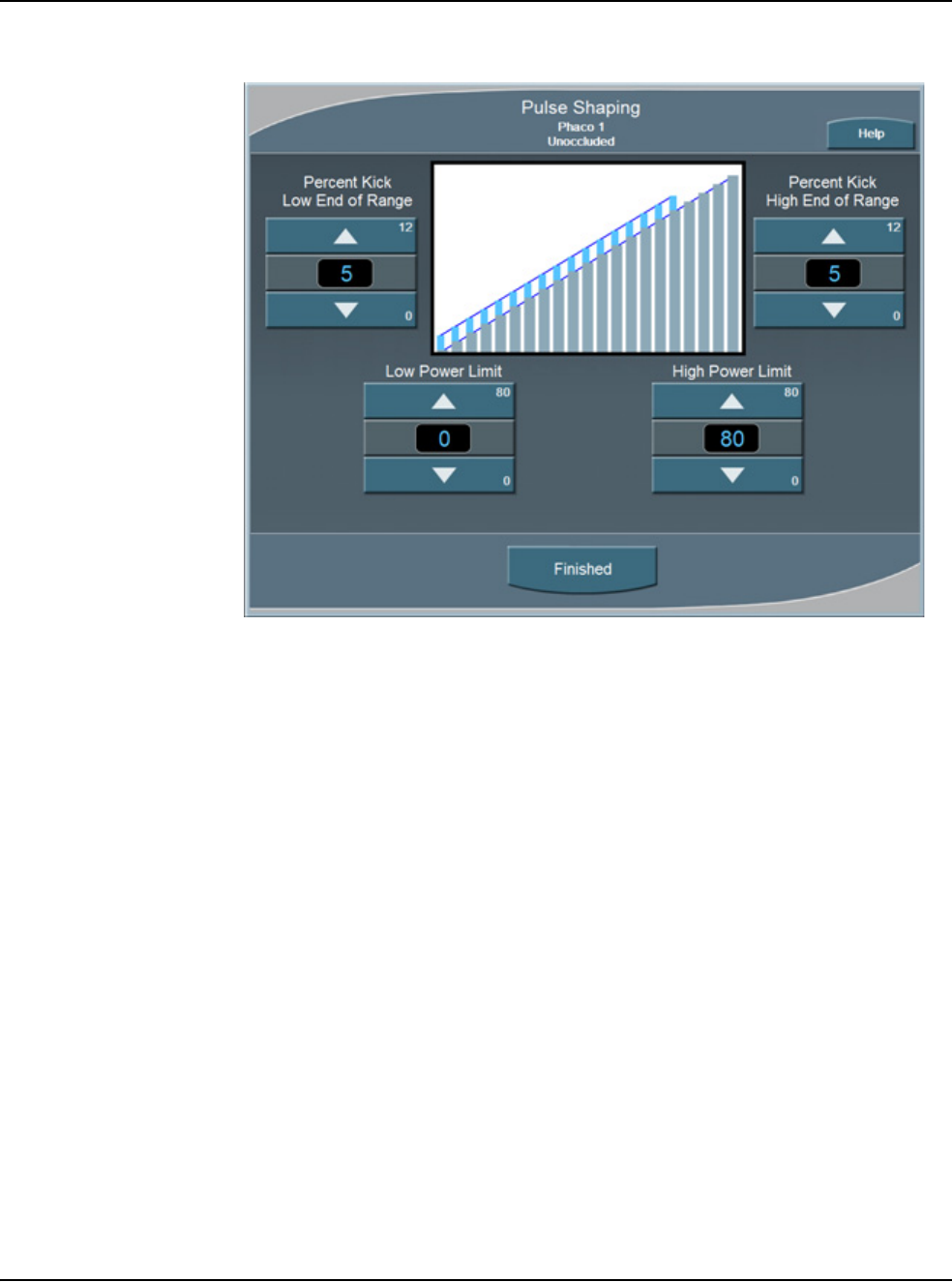
5 • Anterior Segment Surgery Operating Modes
WHITESTAR SIGNATURE™ System Rx Only – Z370147 Rev. C 1108 5-14
Figure 5.13 – Pulse Shaping Screen
There are four settings for WHITESTAR® ICE Pulse Shaping:
• Low Power Limit
•High Power Limit
• Percent Kick Low End of Range
• Percent Kick High End of Range
The Low and High Power Limit settings define the range over which pulse shaping
is applied. When the applied Phaco Power is outside of these limits, no pulse
shaping is applied.
The Percent Kick settings determine the amplitude, or amount of Phaco Power
“kick” that is applied in the first millisecond of Phaco Power application, either in
the low end or the high end of the power range. As the Phaco power increases from
the Low Power limit to the High Power Limit, the percentage of kick is interpolated
for the power ranges in between the two limits.
As an example, if a small kick setting is established for the Low End of the range
and a large kick setting is established for the High End of the range, the kick
percentage gradually increases as the Phaco Power increases. When the Percent
Kick at the Low End is the same as the High End, then the kick remains constant
throughout the Low to High range.
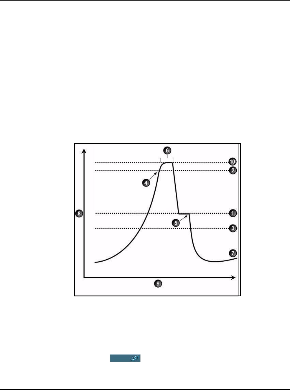
5 • Anterior Segment Surgery Operating Modes
WHITESTAR SIGNATURE™ System Rx Only – Z370147 Rev. C 1108 5-15
Fusion™ Fluidics
Phaco Fusion™ Fluidics Phaco is an intelligent vacuum monitoring system used to
regulate the maximum allowable vacuum that is experienced following an
occlusion of the phaco tip. When the phaco tip becomes occluded, the vacuum
rises. Clearing of the occlusion while the vacuum is at a high level can cause a post-
occlusion surge. With CASE enabled, the System monitors the actual vacuum
levels and when the vacuum exceeds a specific threshold for a specified duration,
the System automatically adjusts the maximum allowable vacuum setting to a
lower predefined CASE maximum vacuum level. When the occlusion is cleared,
the System is automatically restored to the original programmed maximum vacuum
setting. It is possible to have a different maximum vacuum setting when the needle
is occluded than when the needle is not occluded.
The power modulation of the phaco handpiece can be programmed to automatically
change when the phaco tip changes from an unoccluded condition to an occluded
condition.
Figure 5.14 – Fusion™ Fluidics Phaco
The CASE screen shows the settings as a graph. To access the OCCLUSION
MODE™ Phaco and CASE settings:
1. Press the button from the PHACO mode screen.
1. CASE Vacuum 6. Up Time
2. Upper Threshold 7. Vacuum Level
3. Lower Threshold 8. Vacuum.
4. Vacuum Level crosses Upper Threshold. 9. Time.
5. Phaco activated. 10. Max Vac
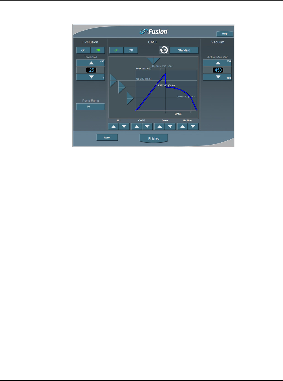
5 • Anterior Segment Surgery Operating Modes
WHITESTAR SIGNATURE™ System Rx Only – Z370147 Rev. C 1108 5-16
Figure 5.15 – Fusion™ Fluidics Phaco Screen
2. Press the On button to turn CASE mode on.
Note: If the Venturi pump option is On, you cannot access the Fusion™ Fluidics
screen. There is no Occlusion Mode or CASE Mode with Venturi.
3. Use the Up and Down arrows at the bottom of the screen to adjust the:
•CASE Vacuum (CASE) – This is the optimum occlusion vacuum setting
•Upper Threshold (Up) – This is the maximum threshold vacuum setting,
which is maintained for the amount of time defined by the Up Time
Threshold.
•Lower Threshold (Down) – After the occlusion is cleared, the vacuum is
reduced to the lower vacuum threshold setting to allow the occlusion to be
safely cleared, and then gradually returned to the previous levels.
4. Use the Right and Left arrows in the graphic to change the Up Time
Threshold. The Up Time Threshold is the maximum time that the maximum
threshold vacuum is maintained.
5. Press Finished to close the screen
Use the Fusion™ Fluidics screen to turn OCCLUSION MODE™ Phaco Off or On.
When OCCLUSION MODE™ Phaco is On, the main PHACO operating screen
provides for alternative Aspiration, Vacuum and Phaco Power settings that are used
when an occlusion is detected.
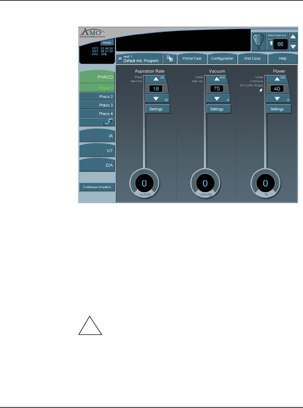
5 • Anterior Segment Surgery Operating Modes
WHITESTAR SIGNATURE™ System Rx Only – Z370147 Rev. C 1108 5-17
Figure 5.16 – PHACO Screen
Vitrectomy
The WHITESTAR SIGNATURE™ System uses a pneumatic guillotine vitrectomy
cutter. The handpieces are designed for cutting vitreous during anterior segment
surgery and operate in conjunction with the Irrigation/Aspiration mode. The cutting
speed can be changed on the touch screen. There are four adjustments related to the
Vitrectomy mode:
• Aspiration Rate
•Vacuum
•Cut Rate
•Footpedal
CAUTION: THE PHACO HANDPIECE AND VITRECTOMY
CUTTER MUST NEVER BE ACTIVATED WITH THE TIPS IN THE AIR.
EXPOSING THE TIP TO AIR DRASTICALLY REDUCES THE USEFUL LIFE
OF THE HANDPIECE. IF POWER IS TO BE INTRODUCED TO THE PHACO
HANDPIECE OR VITRECTOMY CUTTER, THE TIPS MUST BE IN A TEST
CHAMBER FILLED WITH A BALANCED SALT SOLUTION, IN A
CONTAINER OF BALANCED SALT SOLUTION OR IN THE PATIENT’S
EYE.
!
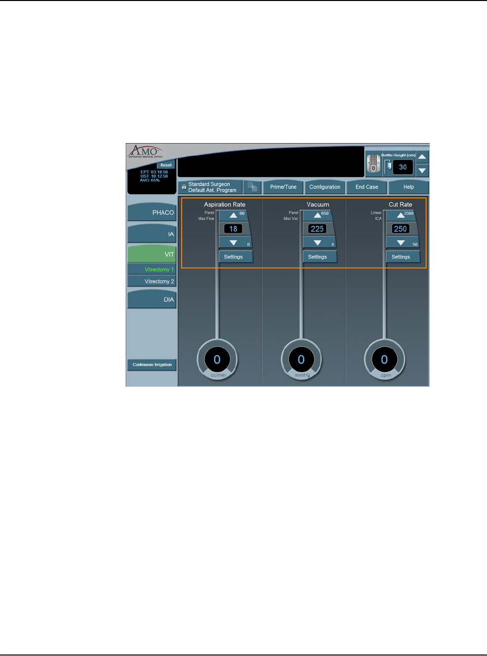
5 • Anterior Segment Surgery Operating Modes
WHITESTAR SIGNATURE™ System Rx Only – Z370147 Rev. C 1108 5-18
Using Vitrectomy
In the left panel, press VIT 1 or VIT 2 to select a submode. VIT 1 is selected by
default.
Note: Each time you select the vitrectomy mode you are prompted to prime the
vitrectomy handpiece. Refer to Chapter 4, Equipment Operation, Priming
for Vitrectomy for detailed information.
Figure 5.17 – Vitrectomy Mode Screen
1. In the main panel, press the Up or Down arrows to increase or decrease the
Aspiration Rate, Vacuum, or Cut Rate.
Note: If the Venturi pump is On, only the Vacuum and Cut Rate Settings are
shown.
2. To program the footpedal, go to Configuration, Surgeons and Programs,
Foot Pedal, Configuration, VIT.
3. Select a Submode to program.
4. Edit the footpedal settings as needed.
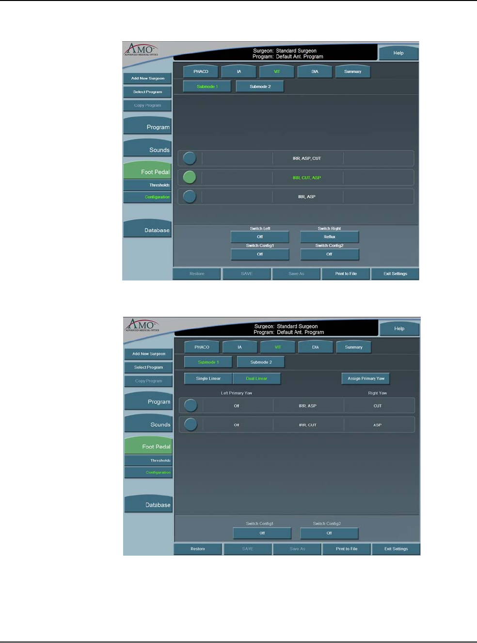
5 • Anterior Segment Surgery Operating Modes
WHITESTAR SIGNATURE™ System Rx Only – Z370147 Rev. C 1108 5-19
Figure 5.18 – Single Linear Foot Pedal Settings Screen
Figure 5.19 – Dual Linear Foot Pedal Settings Screen
5. When finished, press Exit Settings.
6. If no other changes are needed, press End Case to access the SAVE buttons
and save the settings

5 • Anterior Segment Surgery Operating Modes
WHITESTAR SIGNATURE™ System Rx Only – Z370147 Rev. C 1108 5-20
Footpedal Vitrectomy Modes
The footpedal mode selection must be made for ICA, IAC, or Side vitrectomy
(VIT), which determines how the vitrectomy cutter is activated as the footpedal is
pressed from Positions 1 through 3. Use the left side switch to activate the cutter at
the panel rate for Side VIT only.
Table 5.2 Vitrectomy Single Linear Footpedal Modes
Table 5.3 Vitrectomy Advanced Control Pedal (Dual Linear) Modes
Footpedal
Positions Vitrectomy Footpedal Modes
ICA IAC Side VIT
1 Irrigation Irrigation Irrigation
2 Irrigation/Cut Irrigation/
Aspiration Irrigation/
Aspiration
3 Irrigation/Cut/
Aspiration Irrigation/
Aspiration/Cut Irrigation/
Aspiration
Footpedal
Positions Vitrectomy Footpedal Modes
ICA IAC Side VIT
1 Irrigation Irrigation N/A
2 Irrigation/Cut Irrigation/
Aspiration N/A
Yaw Aspiration Cut N/A
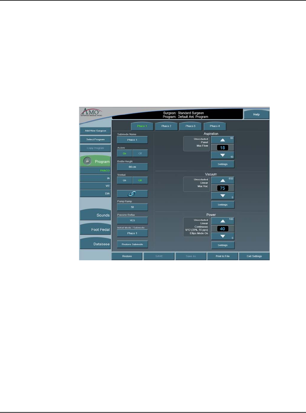
5 • Anterior Segment Surgery Operating Modes
WHITESTAR SIGNATURE™ System Rx Only – Z370147 Rev. C 1108 5-21
Programming the
Modes and Settings Program Configuration
These programmed settings allow for the selection of operational features and
options pertinent to general operation for each mode and submode, the footpedal,
system sounds and the system database.
When the AMO Default Program is selected, all of the modes and submodes are
preset. Although these settings can be changed, they cannot be saved. Use the
defaults as a source to your system settings. All default settings can be easily
viewed on the Mode Configuration screens.
Figure 5.20 – PHACO Program Screen

5 • Anterior Segment Surgery Operating Modes
WHITESTAR SIGNATURE™ System Rx Only – Z370147 Rev. C 1108 5-22
AMO Default Setups
Sounds
Table 5.4 – WHITESTAR SIGNATURE™ System Default Settings
Specific to each surgeon program/setup
Sounds Available Settings AMO Default
Settings
High Vacuum On, Off On
Mode Change Off, Tone, Voice Voice On
Submode Change Off, Tone, Voice Voice On
Value Change On, Off Voice On
Activity Confirmation On, Off Voice On
Vacuum Off–10 6
Diathermy 5–10 6
Phaco Power Off–10 Off
Error 5–10 6
Irrigation Off-10 3
Key Press Off–10 6
Speech Off–10 6
CASE Activation 0–10 5
Master Volume 0–10 10
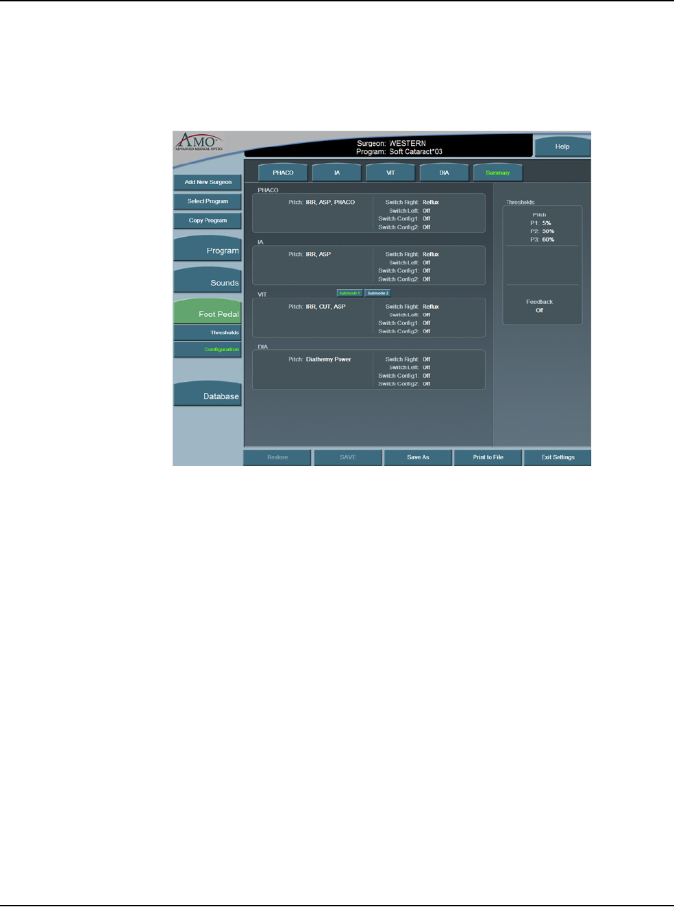
5 • Anterior Segment Surgery Operating Modes
WHITESTAR SIGNATURE™ System Rx Only – Z370147 Rev. C 1108 5-23
Footpedal – AMO Default Settings
The AMO Default footpedal settings for each operating mode are shown on the
System's Summary Screen.
Figure 5.21 – Single Linear Footpedal Summary Settings

5 • Anterior Segment Surgery Operating Modes
WHITESTAR SIGNATURE™ System Rx Only – Z370147 Rev. C 1108 5-24
Table 5.5 – Footpedal Threshold AMO Default Settings
*Switch Assignments
Table 5.6 – Diathermy – AMO Default Settings
Footpedal
Type Parameter Available
Settings AMO Default
Settings
Single Linear Pitch
Regions 1–100% P1=5%
P2=30%
P3=60%
Switch
Position Switch1= *
Switch 2= * Switch1=Off
Switch 2=Off
Right= *
Left= * Right=Off
Left=Off
Feedback On, Off Off
Advanced
Control Pedal
(Dual Linear)
Primary Yaw * Reflux
Pitch Region 1-100% P1=5%
P2=30%
P3=60%
Yaw Position 5-100% Left=50%
Right=50%
Switch
Position Switch1= *
Switch 2= * Switch1=Off
Switch 2=Off
Yaw
Threshold 5% - 100% 5%
Feedback On, Off Off
Surgeon Program Up Surgeon Program Down Previous Major Mode Next Major Mode Previous Active Mode
Next Active Mode Previous Sub Mode Next Sub Mode Toggle SMC Record Bottle Up
Bottle Down Reflux Continuous Irrigation 1-Touch Up (Phaco
Only) 1-Touch Down (Phaco
Only)
Toggle Case (Phaco
Only) Single Vit Cut
(Vitrectomy Only)
Parameter Available
Settings AMO Default Settings
DIA 1 DIA 2
Max Power 5–100% 30% 30%
Power Delivery
Type Linear, Burst,
Panel Linear Burst
Initial Mode/
Submode Any of the
Submode
Names
Phaco 1 Phaco 1

5 • Anterior Segment Surgery Operating Modes
WHITESTAR SIGNATURE™ System Rx Only – Z370147 Rev. C 1108 5-25
Table 5.7 – I/A – AMO Default Settings
Parameter Available
Settings AMO Default Settings
IA1 IA2 IA3
Continuous
Irrigation On, Off Off Off Off
Pump
Selection Venturi
Peristaltic Peristaltic Peristaltic Peristaltic
Bottle Height 0–104 cm
0–42 inches 76 cm
30 inches 50 cm
20 inches 50 cm
20 inches
Max Vacuum 0–650
mmHg 500
mmHg 500
mmHg 15 mmHg
Max
Aspiration/
Mode
(Peristaltic)
0–60 cc/min 26 cc/min
Panel 26 cc/min
Linear 6 cc/min
Panel
Peristaltic
Pump Ramp
Threshold
10–100% 80% 80% 80%
Venturi Pump On, Off Off Off Off
Passive Reflux
(Fusion™
Fluidics Pack)
Yes, No Yes Yes Yes
Passive Reflux
(Fusion™
Dual Pump
Pack)
Yes, No Yes Yes Yes
Initial Mode/
Submode Any of the
Submode
Names
Phaco 1 Phaco 1 Phaco 1
Fluidic Mode Panel, Linear Panel
Aspiration
Linear
Vacuum
Linear
Aspiration
Panel
Vacuum
Panel
Aspiration
Linear
Vacuum

5 • Anterior Segment Surgery Operating Modes
WHITESTAR SIGNATURE™ System Rx Only – Z370147 Rev. C 1108 5-26
Table 5.8 – PHACO – AMO Default Settings
Parameter Available
Settings AMO Default Settings
Phaco 1 Phaco 2 Phaco 3 Phaco 4
Bottle Height 0–104cm
0–42 inches 66 cm
26 inches 76 cm
30 inches 76 cm
30 inches 76 cm
30 inches
Continuous
Irrigation On, Off Off Off Off Off
Pump Selection Venturi
Peristaltic Peristaltic Peristaltic Peristaltic Peristaltic
Max Vacuum
Peristaltic 0–650 mmHg 75 mmHg 300 mmHg 400 mmHg 350 mmHg
Max Vacuum
Venturi 0-600 mmHg 75 mmHg 300 mmHg 400 mmHg 350 mmHg
Venturi Pump On, Off Off Off Off Off
Passive Reflux Yes, No
Fusion™
Fluidics Pack Yes Yes Yes Yes
Fusion™ Dual
Pump Pack Yes Yes Yes Yes
Initial Mode/
Submode Any of the
Submode
Names
Phaco 1 Phaco 1 Phaco 1 Phaco 1
Max Flow/
Aspiration Rate,
Unoccluded
(Peristaltic)
10–60 cc/min 18 cc/min 24 cc/min 18 cc/min 24 cc/min
Fluidics Mode Panel, Linear Panel
Aspiration,
Linear
Vacuum
Panel
Aspiration,
Panel
Vacuum
Panel
Aspiration,
Linear
Vacuum
Panel
Aspiration,
Linear
Vacuum
Occlusion
Threshold 0–Max Vac. 25 mmHg 140 mmHg 60 mmHg 80 mmHg
OCCLUSION
MODETM Phaco
On, Off Off On On Off
CASE Mode On, Off Off Off On On
CASE Upper
Threshold. 0–Max Vac. 100 mmHg 250 mmHg 325 mmHg 300 mmHg
CASE Lower
Threshold. 0–Max Vac. 70 mmHg 175 mmHg 200 mmHg 200 mmHg
Up Time 0–2000 ms 300 ms 300 ms 300 ms 300 ms
CASE Vac 120–650
mmHg 85 mmHg 225 mmHg 250 mmHg 250 mmHg
CASE
One-Touch -2, -1, STD,
+1, +2 STD STD STD STD
Peristaltic Pump
Ramp 10–100% 50% 60% 50% 70%
Power Delivery
Mode
(Unoccluded and
Occluded)
Continuous
Short Pulse
Long Pulse
Low Power
Pulse
High Power
Pulse
Single Burst
Multi-Burst
Continuous
Burst
Continuous Continuous Continuous Continuous
Short Pulse Rate 1–14 pps 6 pps 6 pps 6 pps 6 pps
Long Pulse Rate 1–6 pps 4 pps 4 pps 4 pps 4 pps

5 • Anterior Segment Surgery Operating Modes
WHITESTAR SIGNATURE™ System Rx Only – Z370147 Rev. C 1108 5-27
Table 5.9 – Vitrectomy – AMO Default Settings
WHITESTAR®
Technology
Duty Cycles
2–30 On Time
2–30 Off Time
Predefined: 6/
12, 4/8, 6/4, 6/
8, 8/4, 4/24, 6/
28, 6/24,
8/24, 6/18
6/12 (33%) 6/12 (33%) 6/12 (33%) 6/12 (33%)
Max Aspiration
Rate Occluded 10–60 cc/min 18 cc/min 28 cc/min 14 cc/min 24 cc/min
Max Phaco
Power Occluded 0–100% 40% 30% 10% 40%
Max Ellips™
Phaco Power
Occluded
On, Off Off Off Off Off
Max Phaco
Power
Unoccluded
0–100% 40% 20% 5% 30%
Max Ellips™
Phaco Power
Unoccluded
On, Off Off Off Off Off
Power Delivery
Type Occluded Linear, Panel Linear Linear Linear Linear
Customized to Each Surgeon Program/Setup AMO Default Settings
Parameter Available
Settings VIT 1 VIT 2
Bottle Height 0–104 cm
0–42 inches 30 cm
12 inches 30 cm
12 inches
Continuous Irrigation On, Off Off Off
Pump Selection Venturi
Peristaltic Peristaltic Peristaltic
Max Vacuum/Mode
(Peristaltic) 0–650 mmHg
Panel, Linear 225 mmHg
Panel 225 mmHg
Panel
Max Aspiration Rate/
Mode 0–60 cc/min
Panel, Linear 18 cc/min
Panel 12 cc/min
Panel
Fluidic Mode Panel, Linear Panel
Aspiration
Panel
Vacuum
Panel
Aspiration
Panel
Vacuum
Cut Rate 50–2500 cpm 250 cpm 450 cpm
Footpedal Mode ICA, IAC ICA IAC
Pump Ramp
Threshold 10 - 100% 100% 100%
Venturi Pump On, Off Off Off
Parameter Available
Settings AMO Default Settings

5 • Anterior Segment Surgery Operating Modes
WHITESTAR SIGNATURE™ System Rx Only – Z370147 Rev. C 1108 5-28
Aspiration Rate
The Aspiration Flow Rate is the speed at which material is removed from the eye
through the aspiration tubing. A pump provides the necessary aspiration flow to
withdraw fluid and lens material from the eye chamber through the handpiece.
With this aspiration flow system, the vacuum builds when the aspiration port is
blocked or occluded. The vacuum reduces as the occlusion clears.
You can adjust the rate in 1 cc increments from 0 to 60 cc per minute. You can also
choose Panel or Linear flow.
The flow rate decreases as the vacuum approaches maximum.
To adjust the flow rate:
1. On the Aspiration Rate control panel, press the Up or Down arrows to increase
or decrease the aspiration rate from 0 to 60 cc per minute.
2. Press the Settings button to select Linear or Panel aspiration flow.
The Settings panel appears.
3. Press the Linear or Panel button.
The Linear vacuum rate is linear with respect to the footpedal position. As the
footpedal is pressed through Position 2, the vacuum level travels between 0
mmHg and the maximum preset level as occlusions at the aspiration port occur.
The actual vacuum level is indicated by the vacuum progress shown on the
screen.
The Panel vacuum rate provides a continuous evacuation at the established
vacuum rate. The vacuum builds only when the footpedal is in Position 2 and
an occlusion in the aspiration port is created.
4. Press Finished to close the window.
Passive Reflux
(Fusion™ Fluidics
Pack)
Yes, No Yes Yes
Passive Reflux
(Fusion™ Dual
Pump Pack)
Yes, No Yes Yes
Initial Mode/
Submode Any of the
Submode
Names
Phaco 1 Phaco 1
Customized to Each Surgeon Program/Setup AMO Default Settings
Parameter Available
Settings VIT 1 VIT 2
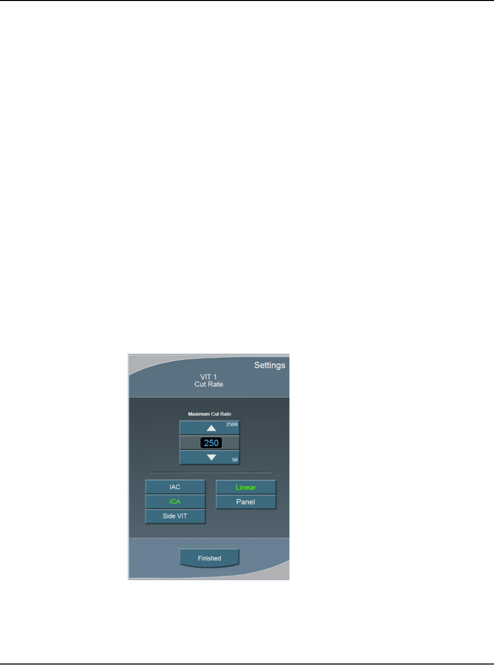
5 • Anterior Segment Surgery Operating Modes
WHITESTAR SIGNATURE™ System Rx Only – Z370147 Rev. C 1108 5-29
Vitrectomy Cutting Rates
Note: Each time you select the vitrectomy mode you are prompted to prime the
vitrectomy handpiece. Refer to Chapter 4, Equipment Operation, Priming
for Vitrectomy for detailed information.
You can vary the Vitrectomy Cut Rate of the vitrectomy cutter from 50-2500 CPM
(cuts per minute) in increments of 50 CPM between 100–1000, and 100 CPM
between 1000–2500 CPM.
Some surgeons prefer a higher rate, which allows the surgeon to perform the same
amount of cutting with smaller “bites” of vitreous. This minimizes motion and is
gentle on the tissue.
To adjust the cut rate
1. On the Cut Rate panel, press the Up or Down arrows to increase or decrease
the cut rate.
2. Press Settings to select either Linear or Panel cutting methods. The Settings
window opens.
Note: Side Vit is only available for use with a single linear foot pedal.
3. Press Linear or Panel button.
4. Press Finished to close the window.
Figure 5.22 – VIT Cut Rate
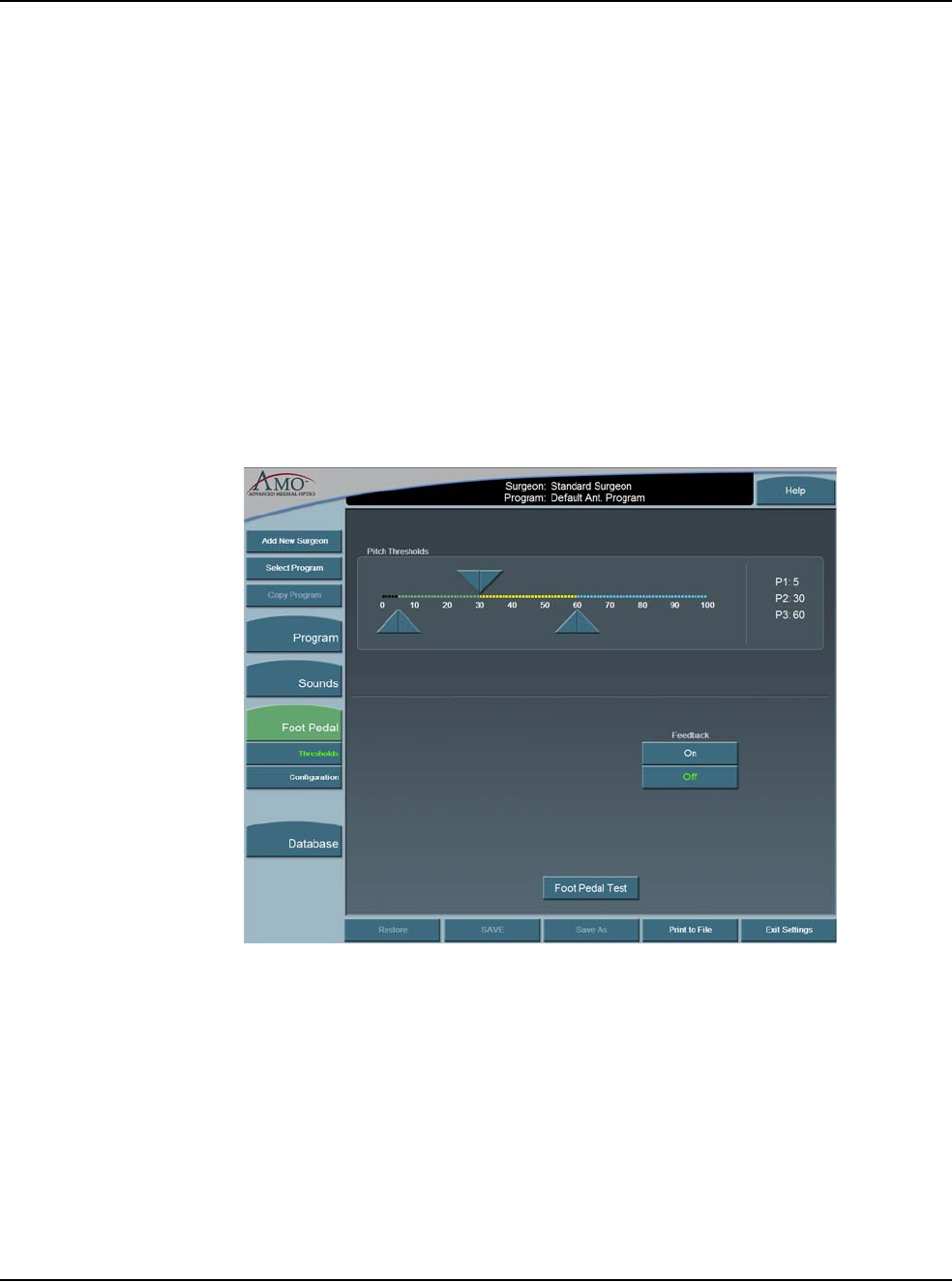
5 • Anterior Segment Surgery Operating Modes
WHITESTAR SIGNATURE™ System Rx Only – Z370147 Rev. C 1108 5-30
Footpedal Settings
The System accommodates multiple configurations for setting footpedal operation.
Each surgeon has one set of footpedal settings for all programs.
The Switch Assignment screen opens when you select On for any of the switches
on the Foot Pedal selection screens. The Switch Assignment screen allows you to
make a selection for that switch.
Footpedal Settings
From the top panel of any operating screen, press Configuration. The program
highlighted on the Main Menu is used.
1. Press Surgeons and Programs in the pop-up window.
2. In the side panel press Foot Pedal.
Figure 5.23 – Foot Pedal Pitch Thresholds - Single Linear
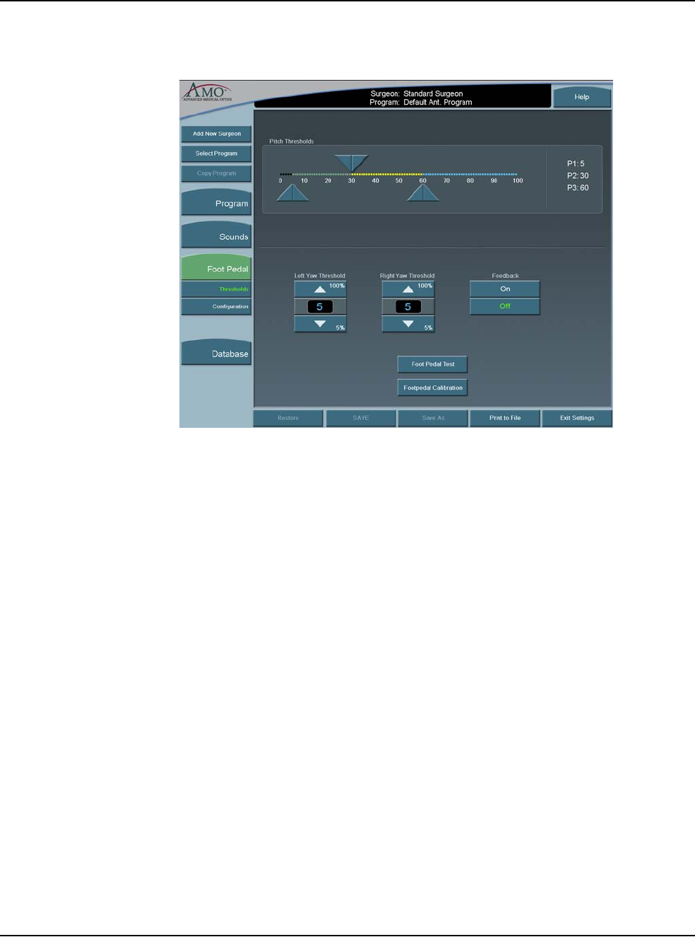
5 • Anterior Segment Surgery Operating Modes
WHITESTAR SIGNATURE™ System Rx Only – Z370147 Rev. C 1108 5-31
Figure 5.24 – Foot Pedal Pitch Thresholds - Advanced Control Pedal (Dual
Linear)
3. Adjust the Yaw Threshold percentage if the Advanced Control Pedal is used.
4. Adjust the Foot Pedal Pitch Threshold settings.
5. Turn the Foot Pedal Feedback On or Off. You can use the Foot Pedal Test
button to test your settings.
6. Press Configuration. The Foot Pedal Settings options are shown.
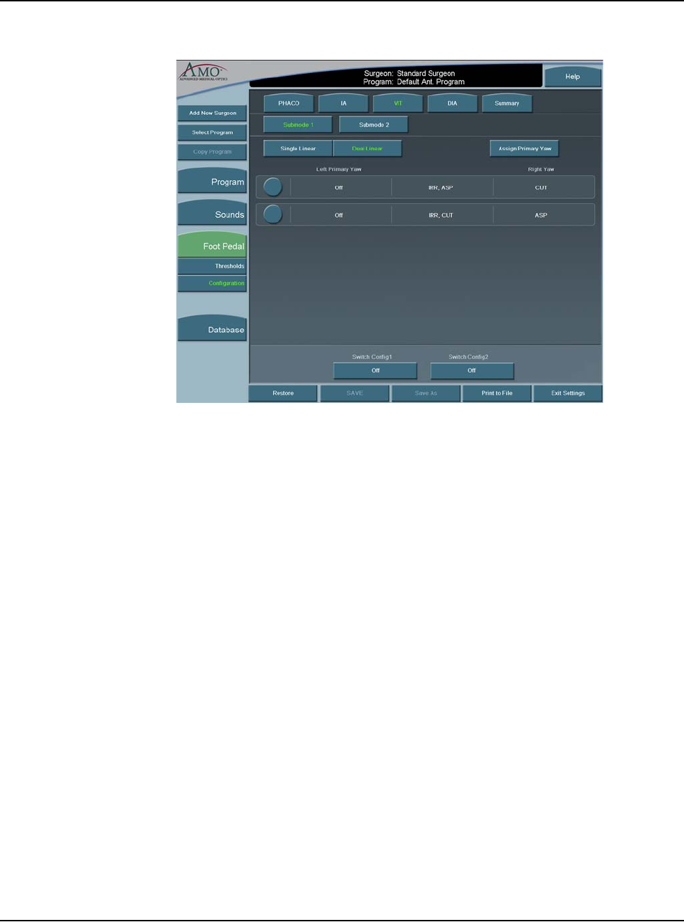
5 • Anterior Segment Surgery Operating Modes
WHITESTAR SIGNATURE™ System Rx Only – Z370147 Rev. C 1108 5-32
Figure 5.25 – VIT Foot Pedal Settings Advanced Control Pedal (Dual Linear)
7. Select the type of foot pedal.
8. Select the Primary Yaw. Each time you select the Assign Primary Yaw button,
the selection is changed from left-to-right or right-to-left.
9. Select the operating modes for that surgery using the top Mode tabs and
complete the footpedal setup for each mode (PHACO, IA, VIT, or DIA). The
footpedal settings are shown in the center of the screen. Select Summary to
view the footpedal settings for all of the modes.
10. Press each of the switches in any of the four modes. A pop-up window is shown
for each switch.
11. Select the Switch Assignment from the list.
Note: WHITESTAR Increment and WHITESTAR Decrement are used to
increase or decrease the Duty Cycles during surgery.
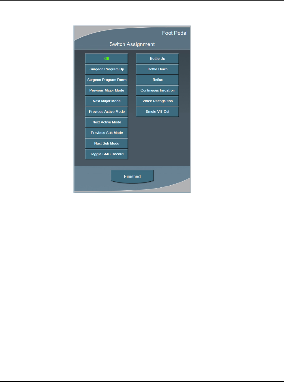
5 • Anterior Segment Surgery Operating Modes
WHITESTAR SIGNATURE™ System Rx Only – Z370147 Rev. C 1108 5-33
Figure 5.26 – Vitrectomy Switch Assignment Pop-up Window
12. Press Finished to close the window.
13. Press SAVE to retain the settings.
Note: If you entered Configuration while in an Operating mode, press Exit
Settings to return to the previous mode.

5 • Anterior Segment Surgery Operating Modes
WHITESTAR SIGNATURE™ System Rx Only – Z370147 Rev. C 1108 5-34
Vacuum
The vacuum is the force exerted on the aspirated fluid in the aspiration tubing. To
make sure you have fluidic balance while in phacoemulsification, you can adjust
the Max Vac from 0 to 650 mmHg (Peristaltic pump), as indicated on the Vacuum
panel.
1. To adjust the vacuum settings:
• To increase or decrease vacuum force, press the Up and Down arrows on the
Vacuum panel.
2. To select Linear or Panel flow, press Settings. The Vacuum Settings pop-up
window appears.
3. Press the Linear or Panel button.
4. Press Finished.
The Linear flow increases from the minimum (0 cc per min) to the maximum preset
flow rate as the surgeon presses the footpedal through Position 2. A higher flow
rate (as delivered from the footpedal) results in a quicker vacuum rise time. A
slower flow rate results in a slower vacuum rise time.
The Panel flow provides a constant evacuation at the preset flow rate when the
footpedal enters Position 2.
End Case
End Case is available in the top panel from any programming or surgical mode.
End Case allows you terminate the programming session or surgical case. If
changes were made to the program settings, you are prompted to SAVE the
settings.
Note: For ease of viewing, the EPT, Ellips EPT, UST and AVG times are shown
in a large font size on the End Case window. The Ellips EPT is shown only
when Ellips™ Technology is On.
Program
Note: SAVE, Save As, and Restore have the same functions on the Program
Configuration screens.
SAVE – Saves the changes to the existing Surgeon Name/Program.
Save As – Saves the program changes (made to an existing program) to a new
program name when you enter a program name.
Restore – Erases any program changes and resets the values back to the last saved
values.
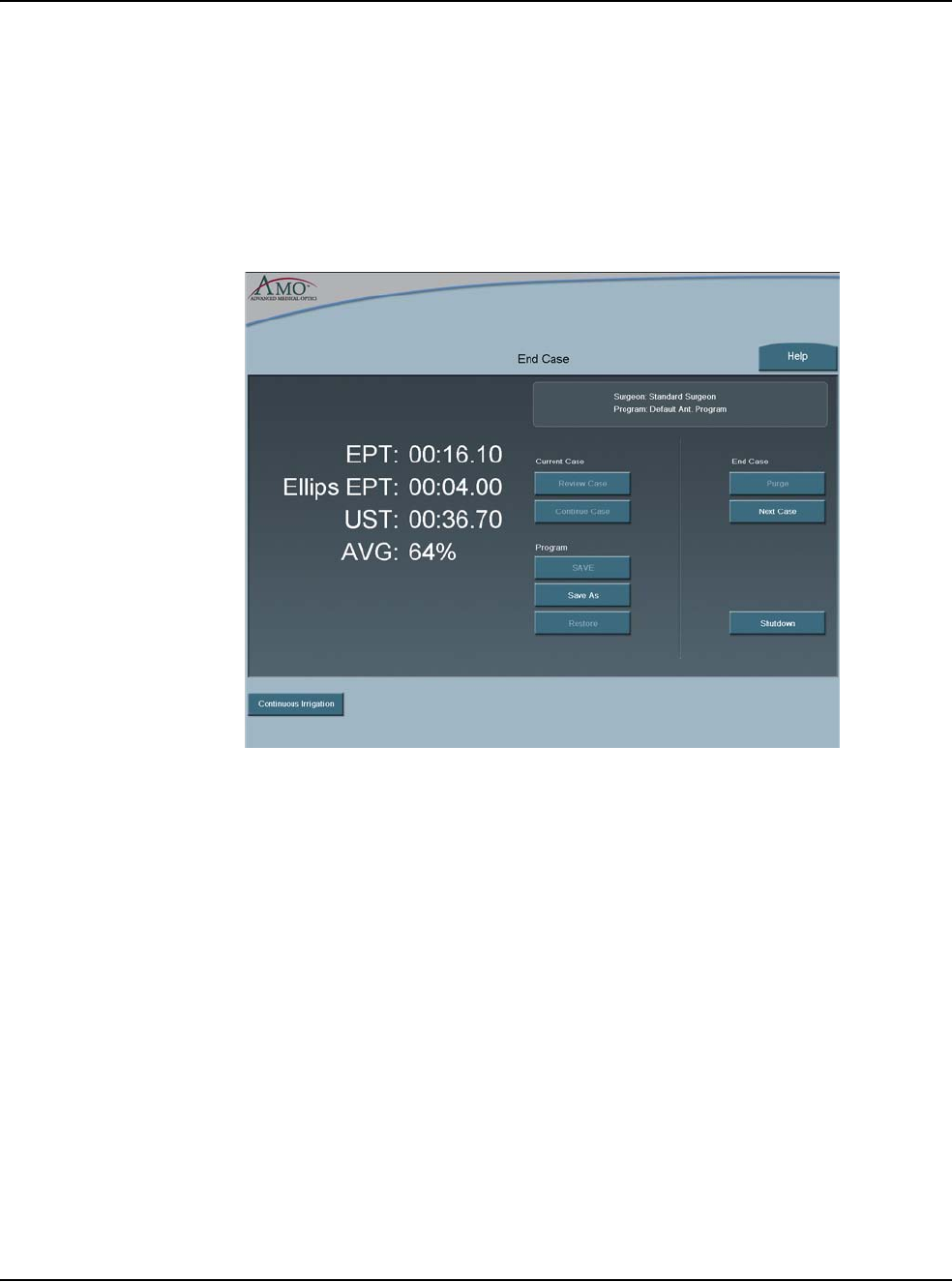
5 • Anterior Segment Surgery Operating Modes
WHITESTAR SIGNATURE™ System Rx Only – Z370147 Rev. C 1108 5-35
End Case
Purge – Select Purge to remove all of the fluid from the irrigation and aspiration
tubing before you remove the tubing cassette.
Next Case – Select Next Case to install a new tubing cassette.
Note: Use a new bottle of balanced salt solution at the start of each case.
Figure 5.27 – End Case Screen
The timers in the upper left corner indicate Effective Phaco Time (EPT), Ultrasonic
(U/S) Time in Footpedal Position 3, and Ellips EPT if Ellips™ Technology is On.
Effective Phaco Time is ultrasound time as a weighted total that takes into account
the amount of power being used:
• at 100% power: 1 sec. U/S Time = 1 sec. EPT
• at 50% power: 1 sec. U/S Time = .5 sec. EPT
Current Case
Review Case – shows the graphical history of the surgery. (Refer to Figure 5.28
Review Case Screen.)
1. Select a shorter time interval to adjust the Time Line Duration and to see
greater case details. For example, 10 Sec shows more detail than 15 Min.
2. Select a longer time interval for an overview of the surgery or sessions, such as
1 hour or 2 hours. This view provides less detail, but gives you a better
indication of the trends over a period of time. Use the << or >> buttons to
change the time intervals. You cannot use the arrow buttons when you view an
active case.
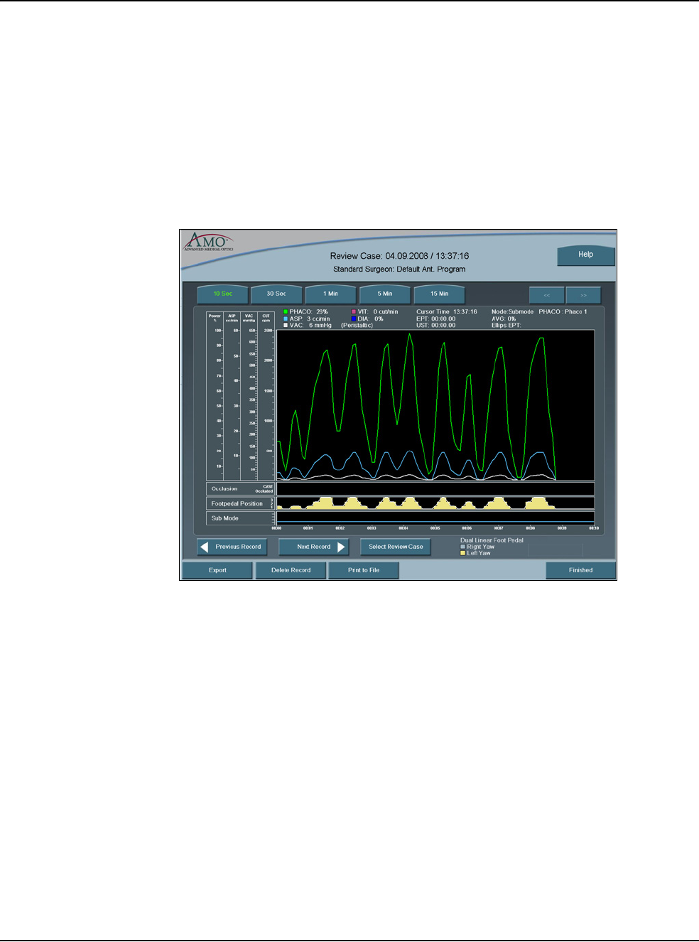
5 • Anterior Segment Surgery Operating Modes
WHITESTAR SIGNATURE™ System Rx Only – Z370147 Rev. C 1108 5-36
3. Press the Select Review Case to select and view a specific surgical case.
4. Press Export to name and save the record to a USB device. Enter a name for
the Case History.
Note: Use only AMO recommended USB stick drives.
5. Use the Print to File to save the data to a file format. The Delete Record
button removes the case from the Record database.
6. Select Finished to close the window.
Figure 5.28 – Review Case Screen
Continue Case – Select Continue Case to return to the current case, after you
selected Review Case or Restore.
Shutdown – Select the Shutdown button to turn the System Off. At the prompt,
press Yes to complete the process.

5 • Anterior Segment Surgery Operating Modes
WHITESTAR SIGNATURE™ System Rx Only – Z370147 Rev. C 1108 5-37
Anterior Segment –
Recommended
Settings
Phaco Power
You can adjust power from 0% to 100% in 5% increments for both Occluded and
Unoccluded phaco tips. The large number in the power panel indicates the selected
maximum Phaco Power. The phaco power can be either Linear or Panel.
1. Linear – Power is controlled with the footpedal, the power increases from 0%–
100% to the maximum preset level. When the footpedal is fully pressed, the
power level is at the maximum preset level. The power increase is indicated by
the power display bar.
2. Panel – Power is delivered consistently at the power level (%) indicated on the
screen. The power level does not change when you press the footpedal.
There are eight choices for delivery of phaco power:
•Continuous
•Short Pulse
•Long Pulse
•Low Power Pulse
•High Power Pulse
•Single Burst (Panel only)
•Multiple Burst (Panel only)
•Continuous Burst (Panel only)
From the PHACO operating screen, press Settings and the Phaco Power selection
screen appears.
Figure 5.29 – Phaco Power Settings
In addition to the eight Phaco Power modes, you can also select the WHITESTAR
Mode. The WHITESTAR® Technology and Ellips™ Technology are discussed
later in this section.
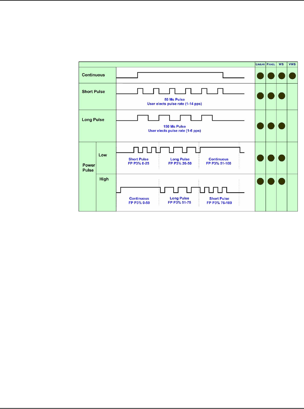
5 • Anterior Segment Surgery Operating Modes
WHITESTAR SIGNATURE™ System Rx Only – Z370147 Rev. C 1108 5-38
Continuous Phaco Power
Continuous Phaco Power delivers continuous, uninterrupted phaco power to the
handpiece and requires no pulse rate setting.
Figure 5.30 – AMO® Phaco Power Modes
Short Pulse Phaco Power
Short Pulse delivers Phaco in pulses of 50 ms when the footpedal is in Position 3.
You can set this in a range of 1 to 14 pulses per second (pps). The actual number of
pps is shown on the button to the right of the Short Pulse button.
To set the Short Pulse range:
1. Press the button to the right of the Short Pulse button. A Settings pop-up
window appears.
2. Press the Up or Down arrow to increase or decrease the pps from 1 to 14.
3. Press Finished to close the window.
Long Pulse Phaco Power
Long Pulse delivers Phaco in pulses of 150 ms when the footpedal is in Position 3.
You can set this in a range of 1 to 6 pulses per second (pps). The actual number of
pps is displayed on the button to the right of the Long Pulse button.
To set the Long Pulse range:
1. Press the button to the right of the Long Pulse button. A Settings pop-up
window appears.
2. Press the Up or Down arrow to increase or decrease the pps from 1 to 6.
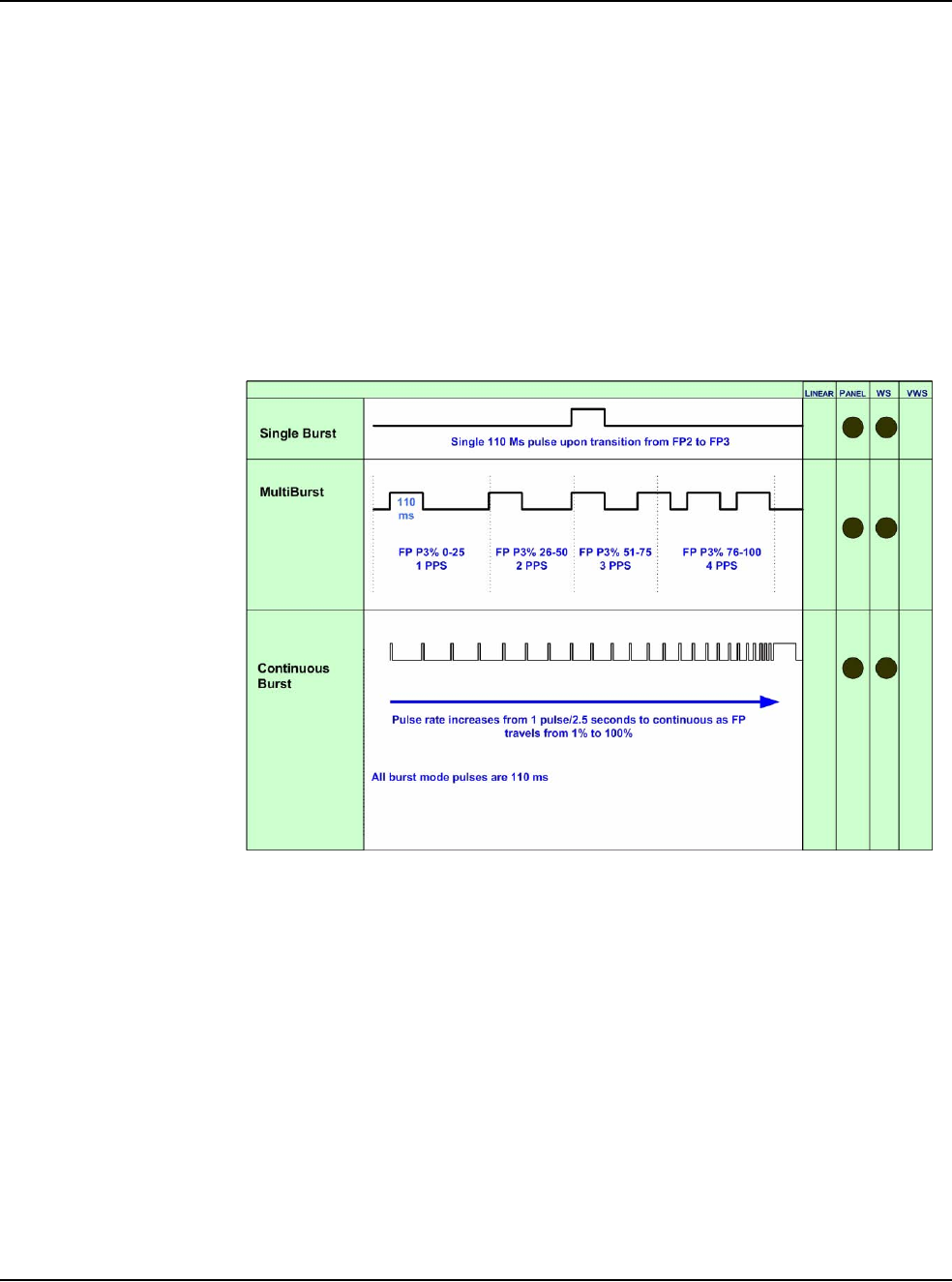
5 • Anterior Segment Surgery Operating Modes
WHITESTAR SIGNATURE™ System Rx Only – Z370147 Rev. C 1108 5-39
3. Press Finished to close the window.
Low Power Pulse Phaco Power
Low Power Pulse generates short pulses of ultrasonic power in footpedal Position
3. When you press the footpedal, the pulses become longer and eventually blend
together to become continuous phaco power.
High Power Pulse Phaco Power
High Power Pulse generates continuous Phaco Power in footpedal Position 3.
When you press the footpedal, the continuous pulse changes into long pulses and
then gradually changes to short pulses.
Figure 5.31 – AMO® Phaco Burst Power Modes
Single Burst Phaco Power (Panel Only)
Single Burst delivers a single burst of ultrasonic power of 110 ms duration when
you press the footpedal to Position 3. You must return to footpedal Position 2,
pause for approximately one-half (.5) second, and then press the footpedal to
Position 3 to obtain an additional burst of energy.
Multiple Burst Phaco Power (Panel Only)
Multiple Burst generates a burst of ultrasonic power of 110 ms duration, with
additional bursts deployed beginning at approximately 1 burst per second when you
press the footpedal to Position 3.
The frequency of burst increases as you press the footpedal. At the maximum level
of footpedal Position 3, the bursts are delivered at the rate of 4 bursts per second.
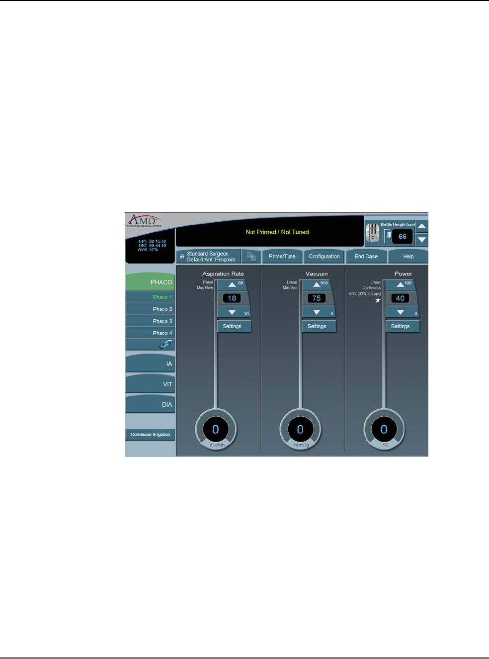
5 • Anterior Segment Surgery Operating Modes
WHITESTAR SIGNATURE™ System Rx Only – Z370147 Rev. C 1108 5-40
Continuous Burst Phaco Power (Panel Only)
Continuous Burst delivers a 110 ms ultrasonic burst duration. As you press the
footpedal through Position 3, the bursts get closer together. At the maximum level
of footpedal Position 3, the bursts blend together, and the power becomes
continuous (at the preset power level).
Override PHACO Submode Settings
You can override the settings for a PHACO submode by selecting the submode,
and either press the Up and Down arrows to increase or decrease Aspiration Rate,
Vacuum, or Power settings, or press Settings on the control panels for Aspiration
Rate, Vacuum, or Power. If you pressed the Settings button, the Settings pop-up
window appears.
Figure 5.32 – Override PHACO Submode Settings
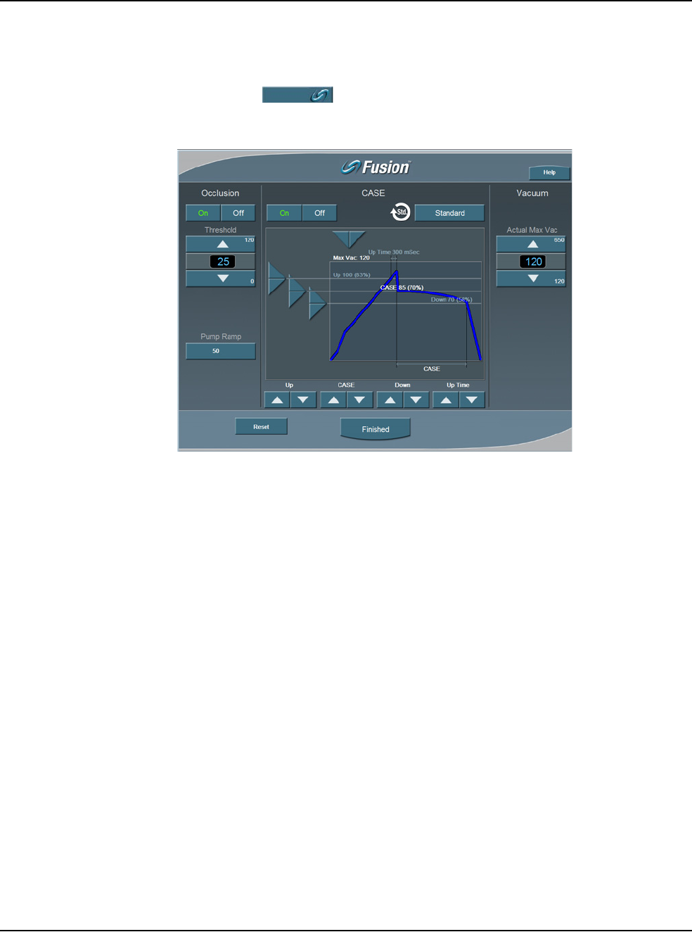
5 • Anterior Segment Surgery Operating Modes
WHITESTAR SIGNATURE™ System Rx Only – Z370147 Rev. C 1108 5-41
OCCLUSION
MODE™ Phaco
Settings
CASE Mode
To access the OCCLUSION MODE™ Phaco and CASE settings:
1. Press the button from the PHACO operating screen.
Figure 5.33 – CASE OCCLUSION MODE™ Phaco
CASE maintains a stable chamber by detecting an impending occlusion break, and
reducing the vacuum before occlusion surge can occur. When the occlusion is
detected, the System waits long enough to allow the particle to be firmly grasped,
and then reduces the vacuum to a lower level in order to allow the occlusion to be
safely cleared. When the occlusion is fully cleared, the vacuum returns to the
previous vacuum level.
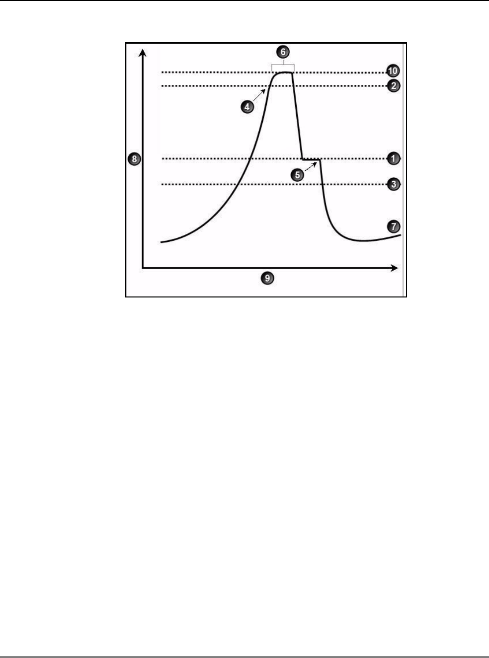
5 • Anterior Segment Surgery Operating Modes
WHITESTAR SIGNATURE™ System Rx Only – Z370147 Rev. C 1108 5-42
Figure 5.34 – CASE OCCLUSION MODE™ Phaco
You can control and customize the CASE behavior by setting the:
1. Upper and Lower Vacuum Threshold levels
2. CASE Vacuum Level
3. “Up Time” delay, which determines the maximum time that the Upper
Threshold Vacuum level is maintained.
1. CASE Vacuum 6. Up Time
2. Upper Threshold 7. Vacuum Level
3. Lower Threshold 8. Vacuum
4. Vacuum Level crosses Upper Threshold 9. Time
5. Phaco activated 10. Max Vac
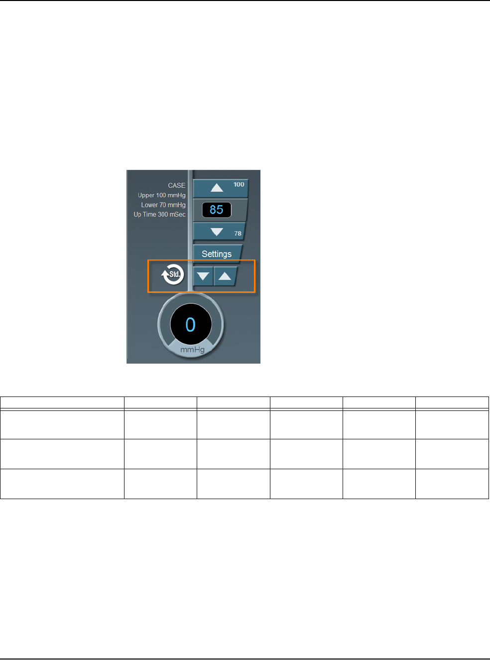
5 • Anterior Segment Surgery Operating Modes
WHITESTAR SIGNATURE™ System Rx Only – Z370147 Rev. C 1108 5-43
CASE One Touch
To simplify the programming of the CASE function, you only need to define the
basic CASE parameters once. The CASE function can then be adjusted quickly and
simply from the CASE One Touch settings on the surgical screen. Using these
controls, the CASE functionality can be changed to provide greater efficiency (Up
arrow) or provide more control (Down arrow) to suit any particular combination of
cataract density, surgical technique or personal preference.
When CASE is On, use the One Touch buttons to adjust the CASE parameters.
Figure 5.35 – CASE One Touch
Table 5.10 – CASE One Touch Parameter Settings
Parameter CASE -2 CASE -1 CASE STD CASE +1 CASE +2
Pump Ramp Setting Program
default Program
default Program
default CASE STD
+10% CASE STD
+20%
CASE Occlusion Delay CASE STD
-200 ms CASE STD
-100 ms Program
default CASE STD
+100 ms CASE STD
+200 ms
CASE Upper
Threshold CASE STD
-5% Program
default Program
default Program
default CASE STD
+5%
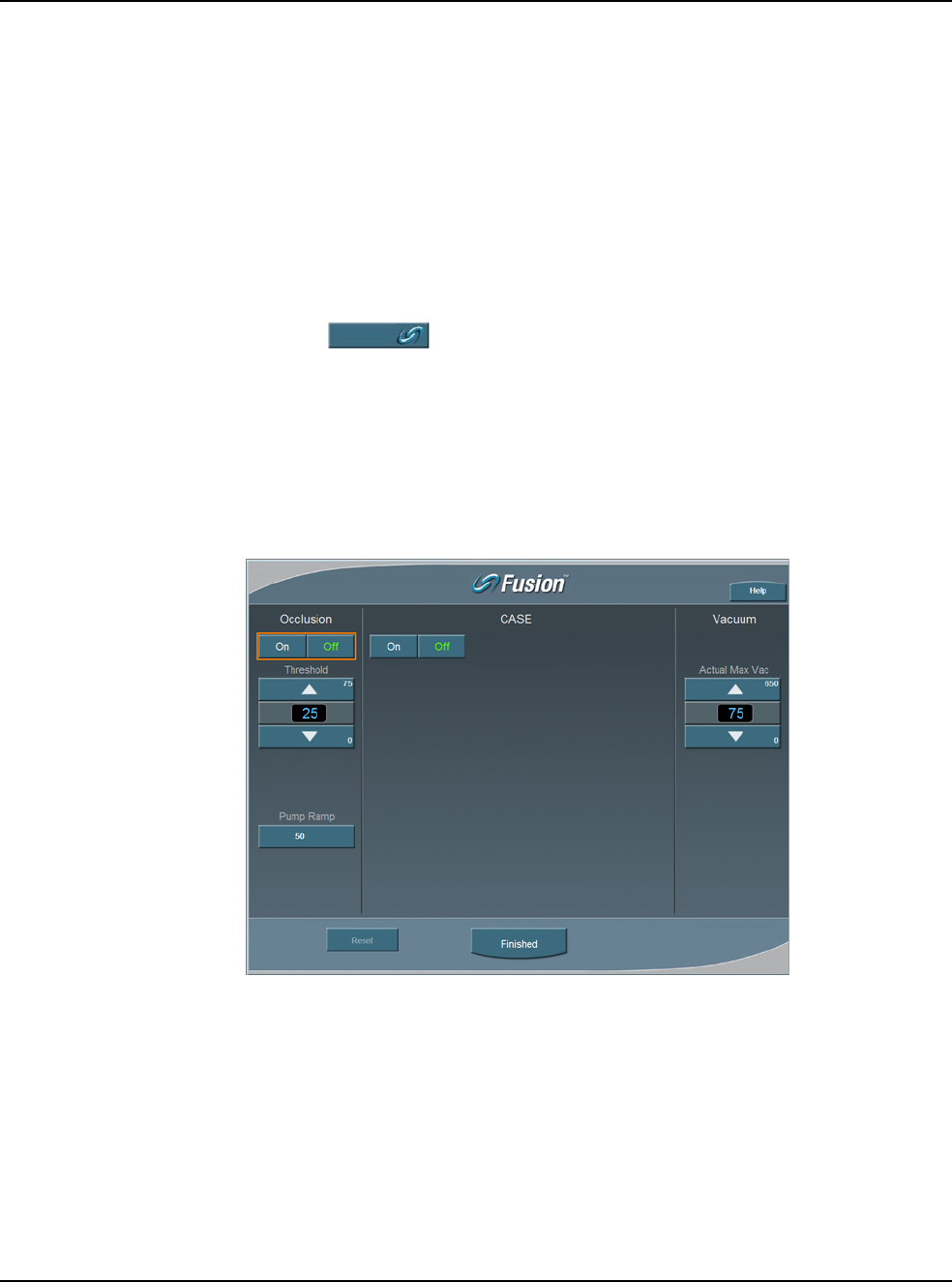
5 • Anterior Segment Surgery Operating Modes
WHITESTAR SIGNATURE™ System Rx Only – Z370147 Rev. C 1108 5-44
OCCLUSION MODE™ Phaco Settings
You can set different Aspiration Rates for occluded aspiration as opposed to
unoccluded aspiration.
With the OCCLUSION MODE™ Phaco you can set a different vacuum rise time
when the phaco tip is occluded without changing the aspiration rate through an
unoccluded needle.
To set the Occluded Aspiration Rate thresholds:
1. Press PHACO.
2. Press on the left of the screen. Three new control panels appear for
Aspiration and Power. The center panel is for a graphical display of the CASE
settings.
3. Press On to set the thresholds.
4. Change the settings in the new control panels as needed.
5. Press Finished to close the window.
Figure 5.36 – OCCLUSION MODE™ Phaco
6. Press Finished to close the screen.
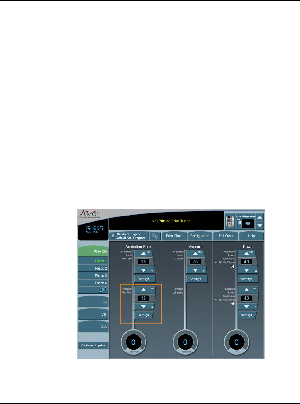
5 • Anterior Segment Surgery Operating Modes
WHITESTAR SIGNATURE™ System Rx Only – Z370147 Rev. C 1108 5-45
Occlusion Vacuum Threshold
In OCCLUSION MODE™ Phaco, you can set an occluded threshold value for
vacuum.
When in OCCLUSION MODE™ Phaco, there is an additional control panel for
Vacuum. The Vacuum Threshold setting lets you choose the vacuum level at which
occluded settings take effect.
To adjust the Occluded Vacuum Threshold:
1. Press the Up or Down arrows, in Occlusion mode, to increase or decrease the
Occluded Vacuum Threshold.
2. When the threshold is decreased, the occlusion settings take effect sooner.
Occlusion Aspiration Rate
In OCCLUSION MODE™ Phaco, you can set a different Max Flow value for
aspiration. There is an additional control panel for aspiration below the standard
aspiration control panel.
To adjust the occluded aspiration rate:
1. In OCCLUSION MODE™ Phaco, press the Up or Down arrows to increase or
decrease the occluded aspiration rate.
Figure 5.37 – Occlusion Aspiration Rate
Or
2. Press Settings. The Occluded Aspiration Rate pop-up window appears.
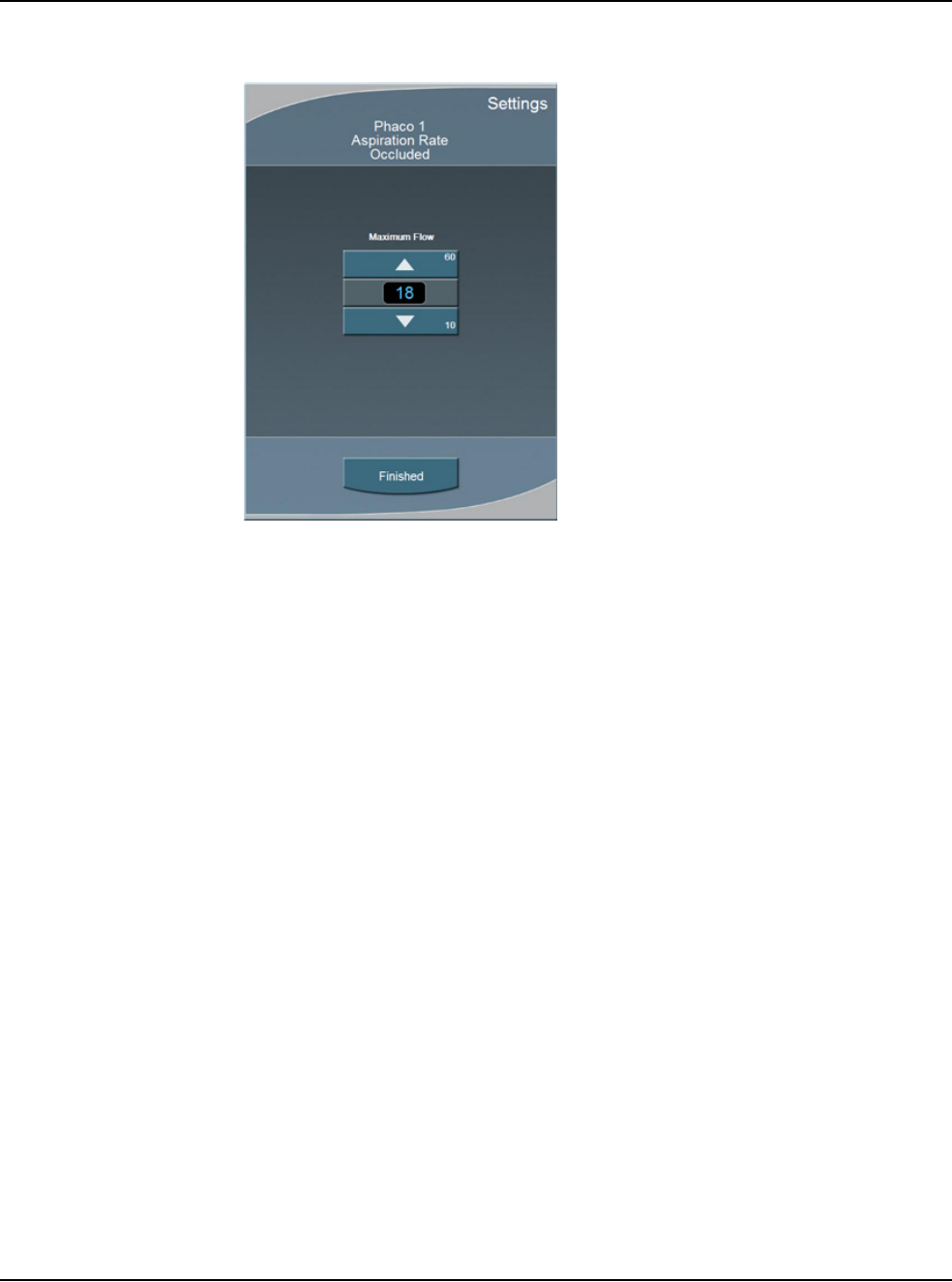
5 • Anterior Segment Surgery Operating Modes
WHITESTAR SIGNATURE™ System Rx Only – Z370147 Rev. C 1108 5-46
Figure 5.38 – Occluded Aspiration Rate Pop-up Window
3. Press the Up or Down arrows to increase or decrease the occluded aspiration
rate.
4. Press Finished to close the window.
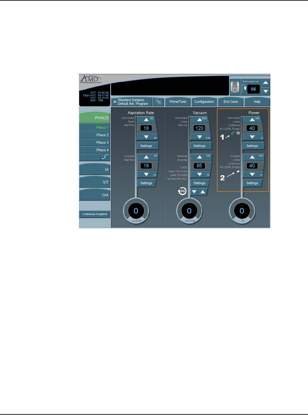
5 • Anterior Segment Surgery Operating Modes
WHITESTAR SIGNATURE™ System Rx Only – Z370147 Rev. C 1108 5-47
OCCLUSION MODE™ Phaco Power Settings
You can set different power levels when the phaco tip is occluded.
When you are in OCCLUSION MODE™ Phaco, there is an additional control
panel for Power.
Figure 5.39 – OCCLUSION MODE™ Phaco Power Settings
To adjust the occluded power delivery:
1. In OCCLUSION MODE™ Phaco, press the Up or Down arrows to increase or
decrease the occluded power level.
2. Press Settings to change other power settings. A Power Settings screen opens.
3. Press Linear or Panel. Depending on whether you select Linear or Panel,
there are a total of nine different power settings you can choose.
4. Press the buttons on the right of the Settings screen to select a power delivery
value.
5. Press the On button to engage WHITESTAR® Technology.
6. Press Finished to close the screen.
Venting an Occlusion
When the aspiration port is blocked or occluded by tissue or other material, the
vacuum pressure builds up. The aspiration flow system vents to the bottle when the
footpedal is released. Another choice is that you can release the footpedal to
Position 1 and that causes the aspiration system fluid to vent using pump rotation.
1. WHITESTAR® Technology with Pulse Shaping with Ellips™ Technology
2. WHITESTAR® Technology without Pulse Shaping
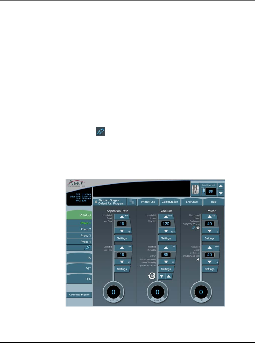
5 • Anterior Segment Surgery Operating Modes
WHITESTAR SIGNATURE™ System Rx Only – Z370147 Rev. C 1108 5-48
These methods release the material at the aspiration port and gives you full control
if the tip accidentally grabs the capsule or iris. The internal fluidic system allows
the desired vacuum level to be maintained when you hold the footpedal at a
constant position. The two adjustments associated with aspiration flow are Max
Vac and Max Flow.
Passive Reflux You can select from either Yes or No. The Yes reverses the pump to vent. The No
option opens a path to the bottle pressure and allows reflux into the eye.
1. Select Configuration.
2. Select Surgeons and Programs.
3. Select the applicable operating mode and submode.
4. Press the Passive Reflux button to select either Yes or No. The system default
is Yes.
Ellips™ Technology Press the Ellips™ Technology button on the Phaco Power Settings screen to
activate. The is shown on the Phaco operating mode screen when Ellips™
Technology is on. Ellips™ Technology can be set for each Phaco submode.
Note: You must have an Ellips™ Phaco handpiece attached to the system before
you can activate the Ellips™ Technology.
Figure 5.40 – Phaco with Ellips™ Technology

WHITESTAR SIGNATURE™ System Rx Only – Z370147 Rev. C 1108 6-1
Select Surgeon/Program
Add a New Surgeon
Edit a Surgeon
Select a Preferred Program
Create a New Program
Edit a Surgeon Program
Copy a Surgeon Program
Delete a Surgeon
Delete a Program
Delete a Database
Lock a Program
Program – Assign Order
6SURGEON PROGRAMS
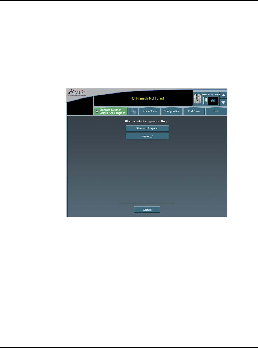
6 • Surgeon Programs
WHITESTAR SIGNATURE™ System Rx Only – Z370147 Rev. C 1108 6-2
Select Surgeon/
Program 1. When the System completes the Self Test routine, you are prompted by the
System to select a Surgeon (by name). If there are no surgeons defined on the
system this screen is not shown.
Note: If your name is not listed, you can use Standard Surgeon, the AMO
default surgeon setup, and then save those settings to your name.
2. After you select a surgeon, the System prompts you to select a Surgeon
Program. If there are no programs defined on the system, the Select A
Surgeon Program screen is not shown.
Figure 6.1 – Select Surgeon Window
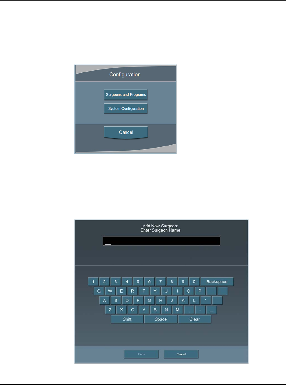
6 • Surgeon Programs
WHITESTAR SIGNATURE™ System Rx Only – Z370147 Rev. C 1108 6-3
Add a New Surgeon To create a new Surgeon program:
1. Press Configuration.
2. Press Surgeons and Programs.
Figure 6.2 – Configuration Pop-up Window
3. The Program Settings screen opens.
4. Press Add New Surgeon. The Keyboard window opens.
5. Enter the name of the surgeon.
6. Press Enter to save the new surgeon and exit the Keyboard window. The new
Surgeon now appears in the list of available surgeons.
Figure 6.3 – Keyboard Screen
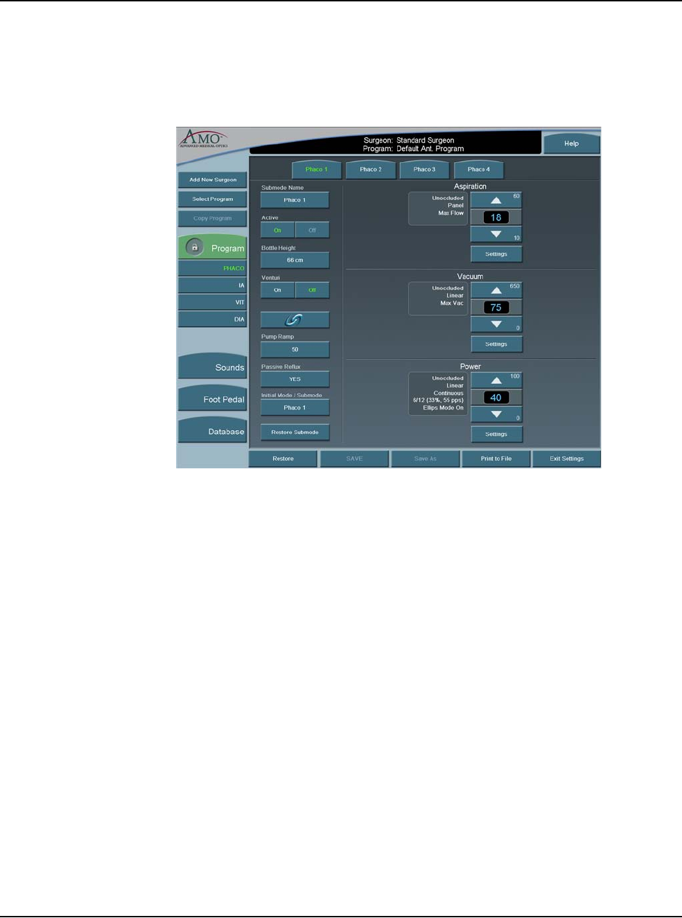
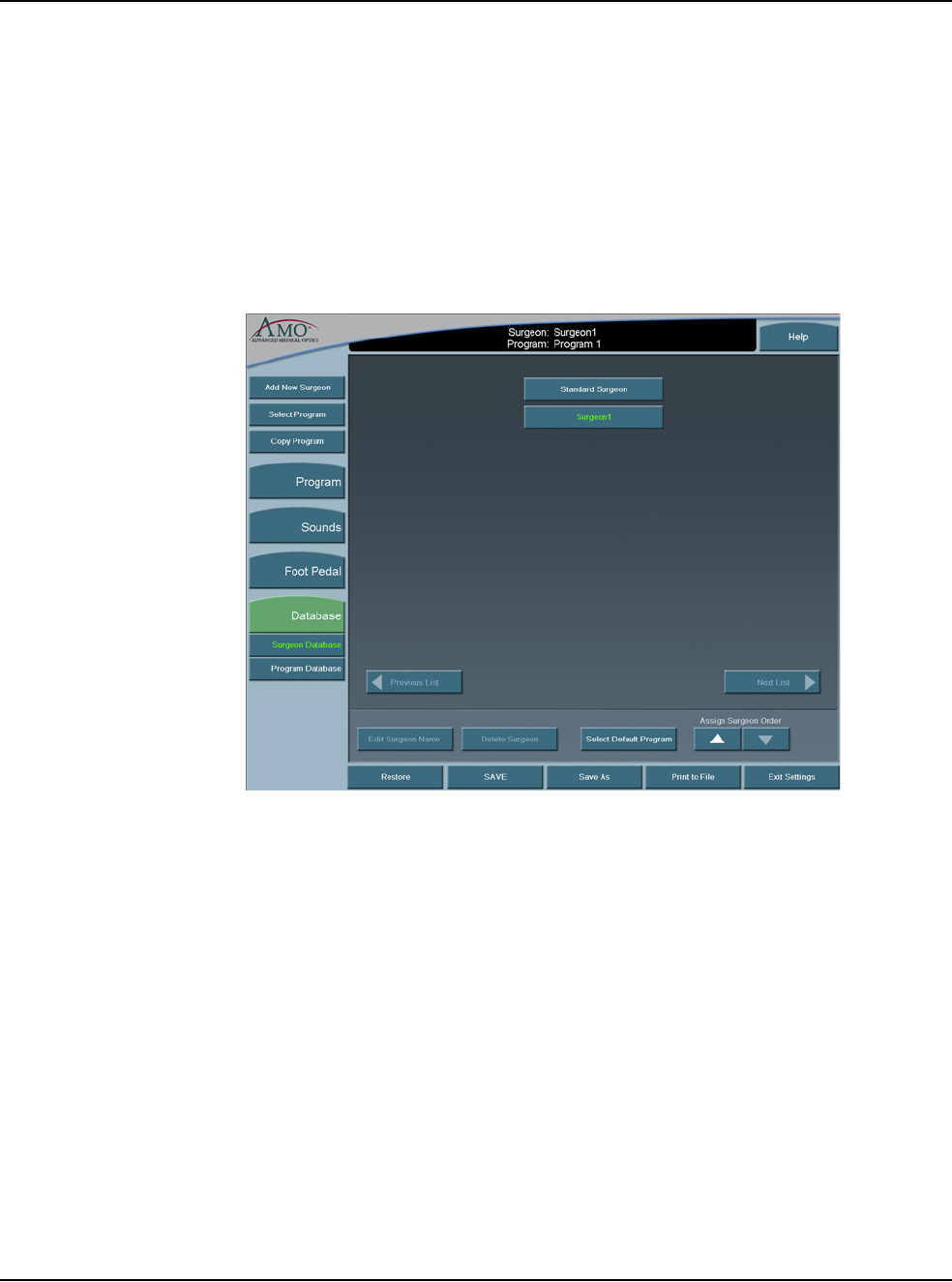
6 • Surgeon Programs
WHITESTAR SIGNATURE™ System Rx Only – Z370147 Rev. C 1108 6-5
8. Press SAVE. If you do not edit any of the settings you can only use Save As.
9. Press Exit Settings.
Edit a Surgeon 1. Press Configuration.
2. Press Surgeons and Programs.
3. Press Database.
4. Press Surgeon Database button.
5. Select a surgeon from the list.
Figure 6.5 – Select Surgeon
6. Press Edit Surgeon Name. The Keyboard window appears.
7. Edit the name.
8. Press Enter.
9. Press Exit Settings.
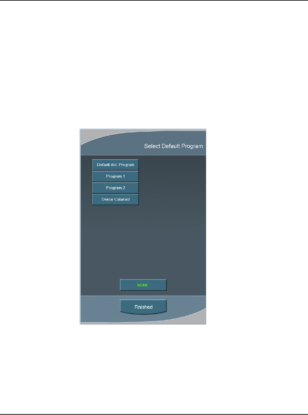
6 • Surgeon Programs
WHITESTAR SIGNATURE™ System Rx Only – Z370147 Rev. C 1108 6-6
Select a Preferred
Program Use the Select Surgeon screen to assign your preferred or default program. the
program selected here is indicated with an asterisk (*) on the Select Program to
Begin screen when the system is started. When you select Next Case the system
asks if you want to return to your preferred program. You are prompted only if you
are not in your preferred program.
1. Press Configuration.
2. Press Surgeons and Programs.
3. Press Database.
4. Press Surgeon Database.
5. Select a surgeon from the list.
6. Select Assign Default Program.
Figure 6.6 – Select Default Program Pop-up
7. Select a program or select None to clear a selection.
8. Select Finished to close the window. Your preferred program is indicated with
an asterisk on the Select Program to Begin screen when the system is started.
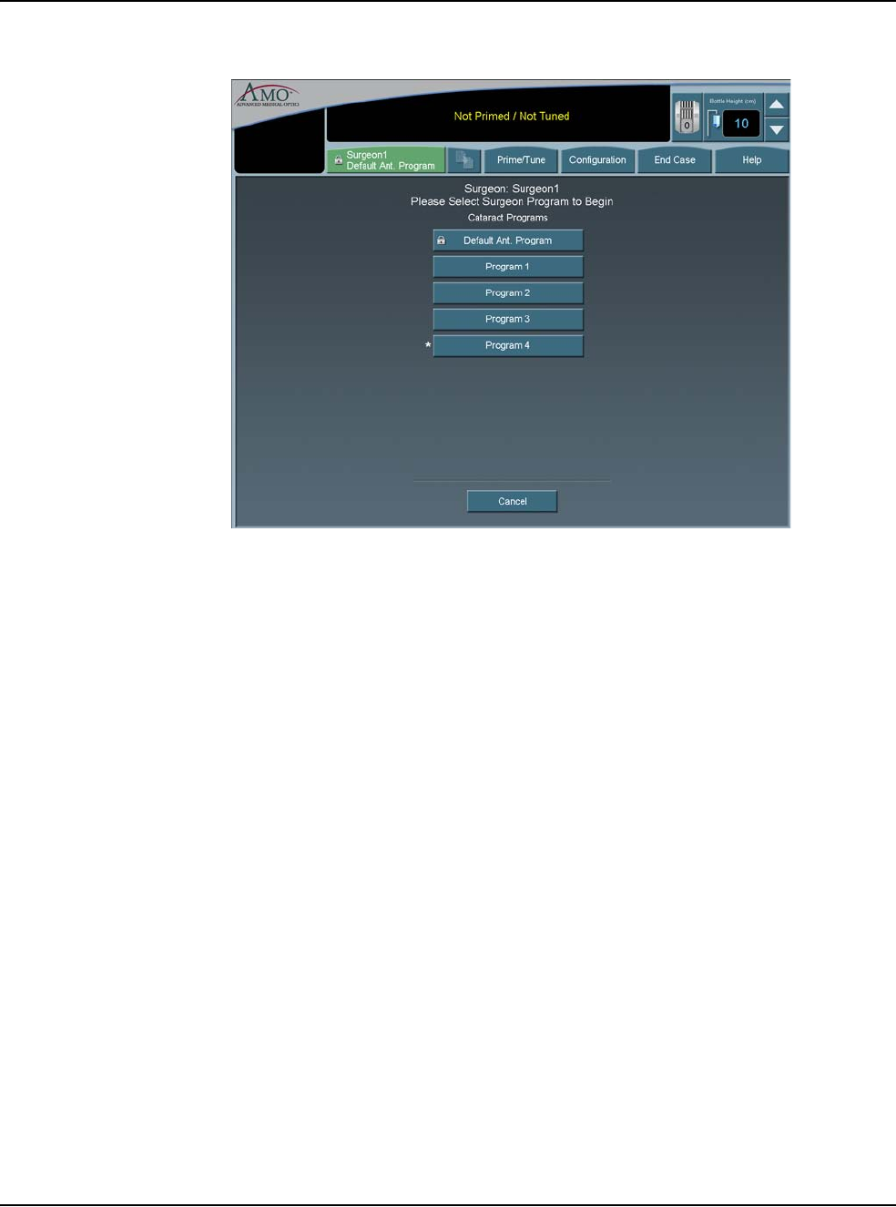
6 • Surgeon Programs
WHITESTAR SIGNATURE™ System Rx Only – Z370147 Rev. C 1108 6-7
Figure 6.7 – Select a Program to Begin Screen

6 • Surgeon Programs
WHITESTAR SIGNATURE™ System Rx Only – Z370147 Rev. C 1108 6-8
Create a New
Program When you create a new surgeon, that surgeon is assigned the AMO Default
Program setup. You can customize a program for that surgeon name with your
preferred settings. You can also create new programs for existing surgeons.
1. Press Configuration.
2. Press Surgeons and Programs.
3. Press Select Program.
4. Select the surgeon or program from the list.
5. Press Enter.
6. Edit the settings for this program on the Settings window. Use the Copy
Program to copy another surgeon's program. Refer to Copy a Surgeon
Program in this chapter.
7. Press Save As. The Keyboard window opens.
8. Enter the name of the program.
9. Press Enter.
10. Press Exit Settings.
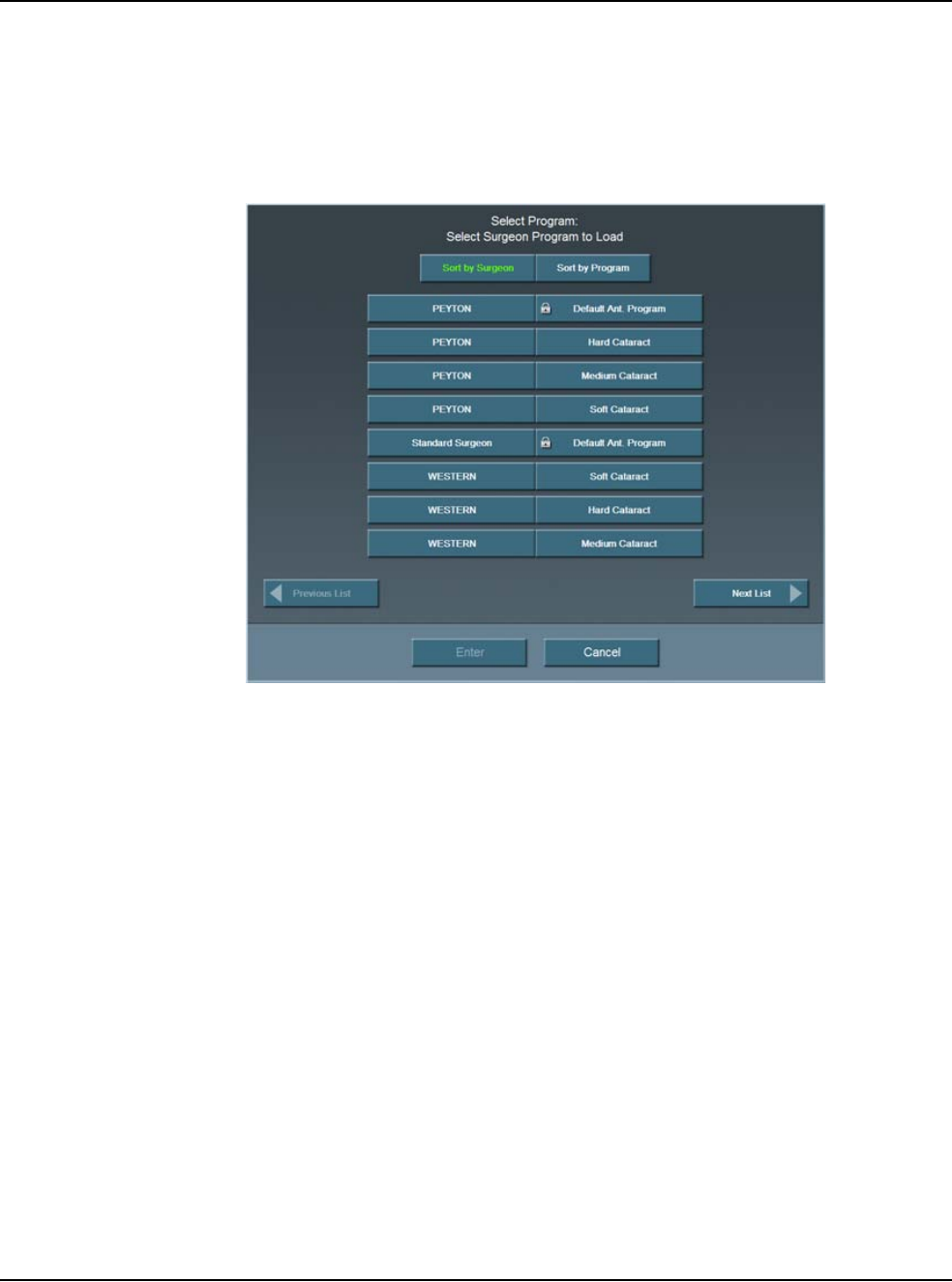
6 • Surgeon Programs
WHITESTAR SIGNATURE™ System Rx Only – Z370147 Rev. C 1108 6-9
Edit a Surgeon
Program 1. Press Configuration.
2. Press Surgeons and Programs.
3. Press Select Program.
4. Select the surgeon or program from the list.
Figure 6.8 – Select Program
5. Press Enter.
6. Select the mode and submode to edit.
7. Edit the settings for this program on the Settings window.
8. Press SAVE.
9. Press Exit Settings.

6 • Surgeon Programs
WHITESTAR SIGNATURE™ System Rx Only – Z370147 Rev. C 1108 6-10
Copy a Surgeon
Program You can copy the settings of one surgeon program for use by another surgeon.
To copy a surgeon program:
1. Press Configuration.
2. Select Surgeons and Programs.
3. Press Copy Program and select the Surgeon or Program you want to copy
from the list. This copies all of the settings of the selected program and the
submodes.
Note: If Standard Surgeon is the active surgeon, Copy Program is not
available to the user. Press Select Program to change the surgeon and
program.
4. Press Enter.
5. Press Save As at the bottom of the screen. The Keyboard window opens.
6. Enter the new name for the program.
7. Press Enter to save the new program and exit the Keyboard window. The new
program now appears in the list of available programs.
8. Press Exit Settings.

6 • Surgeon Programs
WHITESTAR SIGNATURE™ System Rx Only – Z370147 Rev. C 1108 6-11
Delete a Surgeon Use Delete Surgeon to remove a surgeon from the Select Surgeon screen. You
cannot delete the current surgeon.
Note: You cannot delete a current surgeon or a surgeon that is selected on the
Settings screen.
1. Press Configuration.
2. Press Surgeons and Programs.
3. Press Database.
4. Press Surgeon Database.
5. Select a surgeon to delete.
6. Select Delete Surgeon. A delete confirmation pop-up appears.
Figure 6.9 – Delete Confirmation Pop-up Window
7. Press Yes.
8. Select Exit Settings.
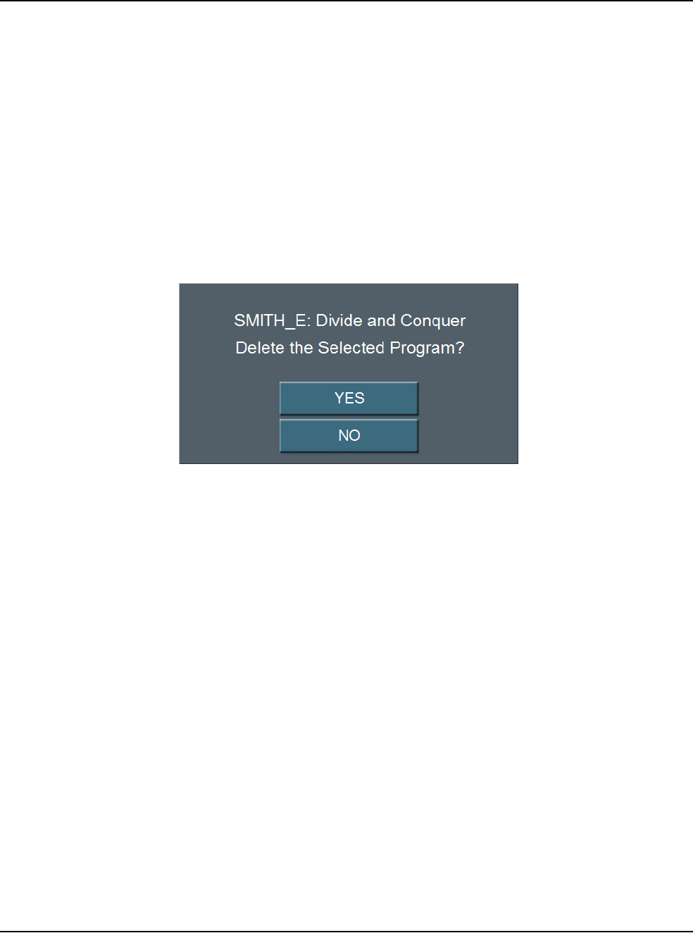
6 • Surgeon Programs
WHITESTAR SIGNATURE™ System Rx Only – Z370147 Rev. C 1108 6-12
Delete a Program Use Delete Program to remove a surgeon program from the Select Program
screen. You cannot delete the current program.
Note: You cannot delete a current program or a program that is selected on the
Settings screen.
1. Press Configuration.
2. Press Surgeons and Programs.
3. Press Database.
4. Press Program Database.
5. Select a program to delete.
6. Select Delete Program. A delete confirmation pop-up appears.
Figure 6.10 – Deletion Confirmation
7. Press Yes.
8. Select Exit Settings.
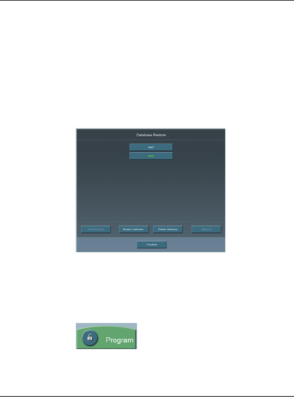
6 • Surgeon Programs
WHITESTAR SIGNATURE™ System Rx Only – Z370147 Rev. C 1108 6-13
Delete a Database You can delete a database from your memory device. Contact your AMO Service
Representative to delete a database from your system's hard drive.
Note: Use only AMO recommended USB stick drives.
1. Insert the USB flash drive into the port on the back of the system.
2. From Configuration, press System Configuration to access the Diagnostic
screen.
3. Press Restore All.
4. Press the database to delete from the list.
5. Press Delete Selection.
6. Press OK at the confirmation window.
7. Press Finished to close the window.
Figure 6.11 – Database Restore Screen
Lock a Program Press the open padlock at any time to lock the program. To edit a locked program,
use Save As and rename the program.
Note: When a program is locked the program cannot be unlocked. You cannot
edit a locked program.
Figure 6.12 – Program Lock Button
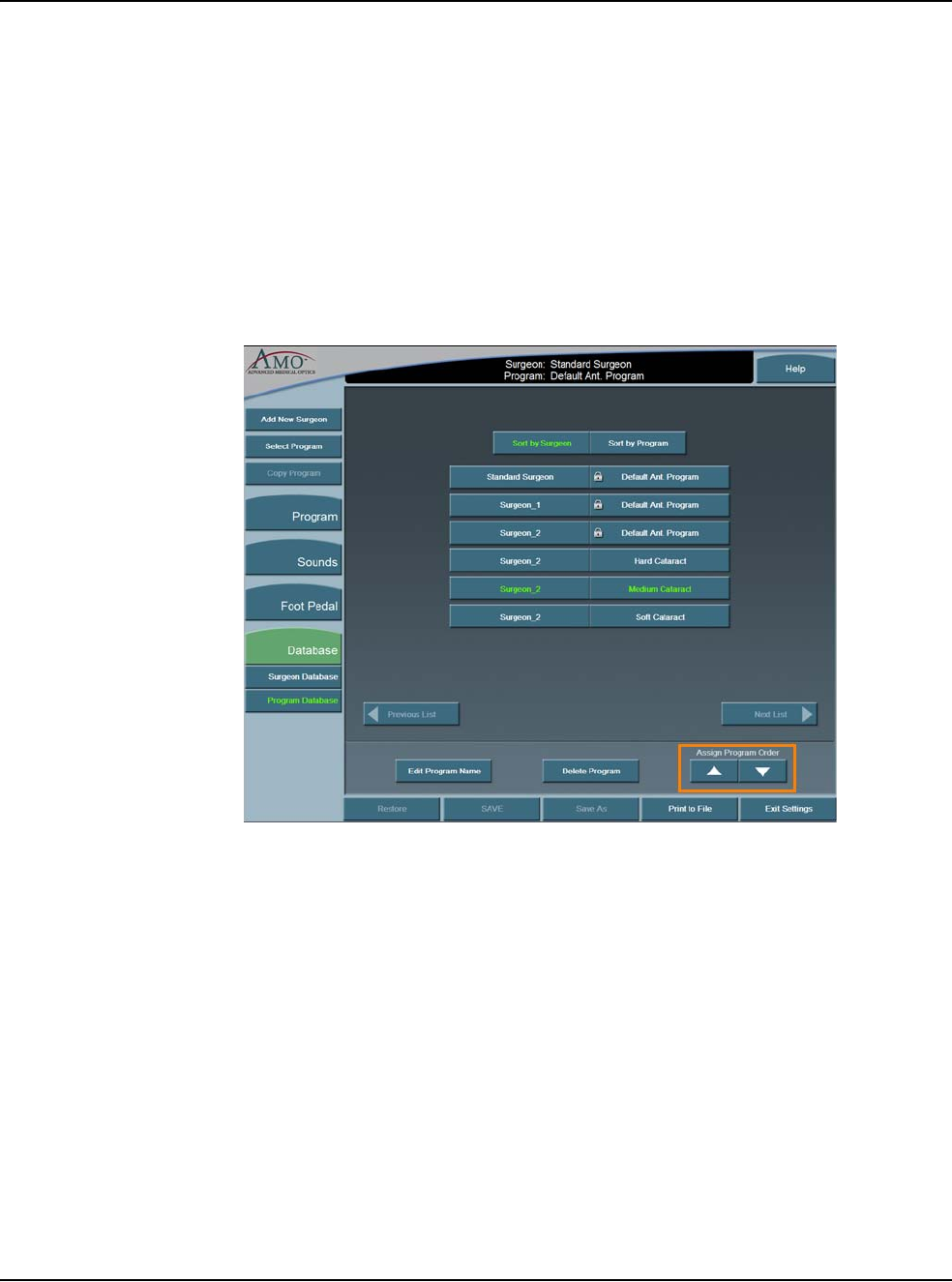
6 • Surgeon Programs
WHITESTAR SIGNATURE™ System Rx Only – Z370147 Rev. C 1108 6-14
Program – Assign
Order Use Program Assign Order to change the order in which the surgeon names are
shown on the Select Surgeon window.
1. Press Configuration.
2. Press Surgeons and Programs.
3. Press Database.
4. Select Program Database. A list of programs appears.
5. Select a program.
6. Use the Assign Program Order Up and Down arrows to move the Program.
The arrows are found at the bottom of the window.
Figure 6.13 – Surgeon and Program Databases
7. Repeat steps 5 and 6 until you are satisfied with the order.
8. Select Exit Settings.

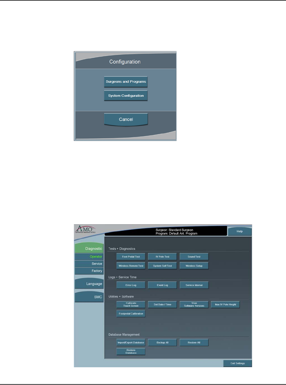
7 • Diagnostics
WHITESTAR SIGNATURE™ System Rx Only – Z370147 Rev. C 1108 7-2
Diagnostics To access diagnostics:
1. Press Configuration.
Figure 7.1 – Configuration Pop-up Window
2. Press System Configuration. On the System Configuration screen, Diagnostic
is selected by default.
The Diagnostic screen shows the various Diagnostic Routines, Logs, System
Utilities and Database Management functions that can be accessed by the Operator.
Press the button for the diagnostic routine you want to run or view. Follow the
instructions on the screen to complete the test process. The Service and Factory
Diagnostic routines can only be accessed by authorized AMO service personnel.
Figure 7.2 – Diagnostics Screen
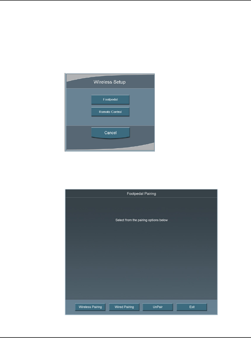
7 • Diagnostics
WHITESTAR SIGNATURE™ System Rx Only – Z370147 Rev. C 1108 7-3
Wireless Footpedal
Setup You can pair the Wireless Foot Pedal (Advanced Control Pedal) to the system with
either the Footpedal Cable or wireless. The Wireless Foot Pedal uses Bluetooth®
technology to communicate with the system. The Wireless Foot Pedal has a range
of ten (10) feet from the system.
1. Press Wireless Setup.
2. Select Footpedal.
Figure 7.3 – Wireless Setup Pop-up Screen
3. Select either Wireless Pairing or Wired Pairing. To use Wired Pairing you
must have the Footpedal Cable attached to the system.
Figure 7.4 – Footpedal Pairing Screen
4. Follow the instructions shown on the screen.

7 • Diagnostics
WHITESTAR SIGNATURE™ System Rx Only – Z370147 Rev. C 1108 7-4
Figure 7.5 – Wireless Footpedal Pairing Instructions
5. Press Exit to close the screen and access the Foot Pedal Test screen.
• If the blue light is on, the wireless foot pedal is paired.
• If the blue light is flashing the wireless foot pedal is not paired.
• If the green light is on, the batteries in the foot pedal are charged.
• If the green light is blinking, the batteries in the wireless foot pedal need to
be charged. Attach the cable to charge the batteries.
6. Use UnPair to unpair either of the Advanced Control Pedals (dual linear) from
the system.
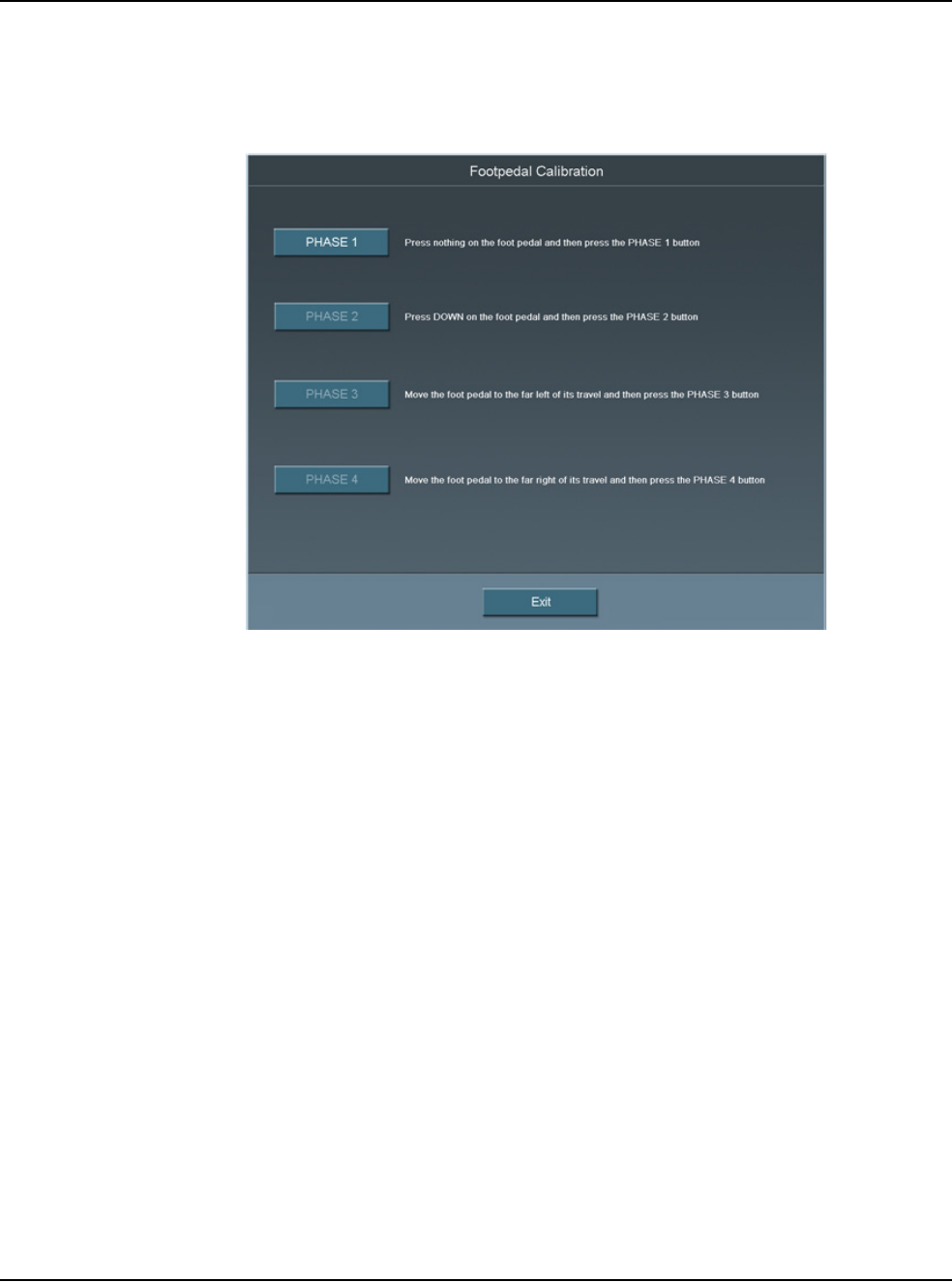
7 • Diagnostics
WHITESTAR SIGNATURE™ System Rx Only – Z370147 Rev. C 1108 7-5
Wireless Foot Pedal
Calibration To maintain optimal use of the foot pedal, the wireless foot pedal must be
calibrated from time to time.
Figure 7.6 – Footpedal Calibration Screen
1. Press Footpedal Calibration from the Diagnostic screen. The Footpedal
Calibration screen can also be accessed from the Foot Pedal Threshold screen.
Note: Only press the foot pedal when you are instructed. If you press the foot
pedal at any other time the calibration of the foot pedal can fail.
2. Follow the instructions shown on the screen. The Calibration screen closes
automatically when completed and the Foot Pedal Test screen opens.
3. Test the foot pedal.
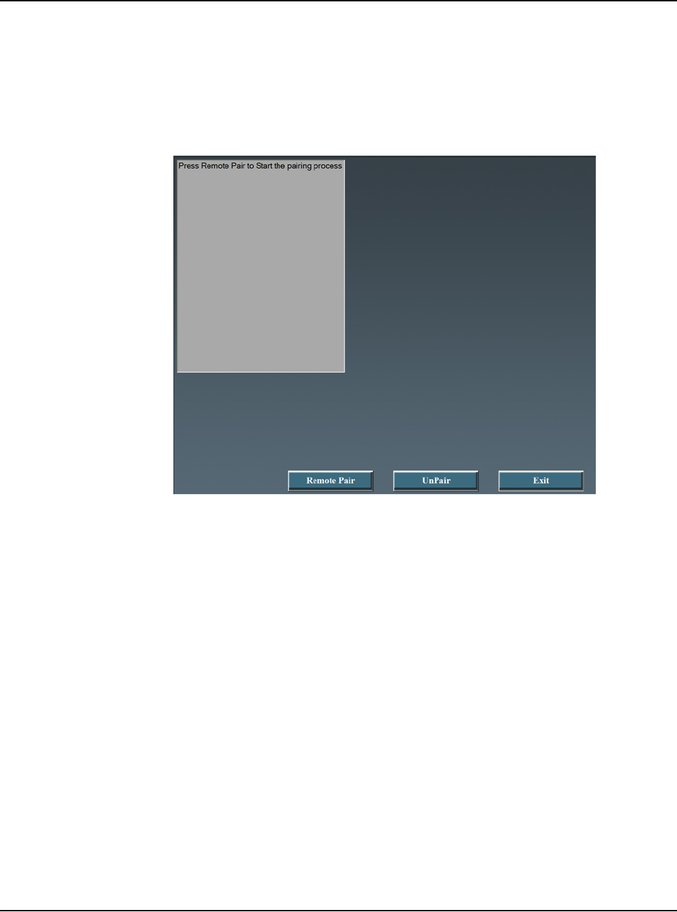
7 • Diagnostics
WHITESTAR SIGNATURE™ System Rx Only – Z370147 Rev. C 1108 7-6
Wireless Remote
Control Setup Use the Wireless Setup button to connect the System with a Wireless Remote
Control.
Note: Make sure that the Backlight feature for the Wireless Remote Control is off
(before you start the Wireless Setup process).
Figure 7.7 – Wireless Setup Screen
1. Press Wireless Setup.
2. Select Remote Control.
3. Press Remote Pair.
4. Follow the messages shown on the screen.
5. For the Remote Control:
• Press the corresponding buttons on the wireless remote control as prompted.
If Remote Pair fails, follow the instructions on the screen.
• Press the buttons on the wireless remote control.
• Verify for each button that the corresponding button on the screen lights. If
the button does not light on the screen, the test fails. If the test fails contact
AMO for technical service.
6. Press Exit to close the window.
7. Press the Unpair button to unpair the Remote.

7 • Diagnostics
WHITESTAR SIGNATURE™ System Rx Only – Z370147 Rev. C 1108 7-7
Calibrate Touch
Screen The System touch screen needs to be calibrated as part of the system maintenance.
Press Calibrate Touch Screen to start the calibration procedure.
1. Press the center of the target circle until the Touch message changes to
Release.
Figure 7.8 – Touch Screen Target Circle
2. When released, the circle moves to the next point to be calibrated.
3. Repeat Step 1 for all of the calibration points.
4. Press Accept when all of the calibration points are completed.


8 • Check-out Precautions
WHITESTAR SIGNATURE™ System Rx Only – Z370147 Rev. C 1108 8-2
System Check-out The purpose of the check-out procedure is to verify that the System is installed and
operating properly. The check-out procedure must be performed at least prior to the
first case of the day and any time program changes are made as outlined in the
following steps. The IA mode and handpiece are tested first, then the PHACO
mode and handpiece, so that the phaco handpiece (which is used first) is set up and
ready for surgery.
If any of the check-out steps are not successfully performed, they must be repeated.
If the instrument still does not work correctly, refer to Chapter 10, “Error Messages
Troubleshooting and Diagnostics”.
Note: Refer to WARNINGS in Chapter 3, “System Setup” before you set up the
System.
Set-Up and Prime/Tune
Refer to the System Setup and Equipment Operation chapters of this manual for
instructions on installing the tubing and priming/tuning the system.
Irrigation and Aspiration
1. Connect the tubing to the IA handpiece.
2. Select IA mode.
3. Hold the test chamber near the handpiece tip, press and hold the footpedal in
Position 1.
4. Observe the irrigation flow.
Phacoemulsification
1. Connect the tubing to the phaco handpiece.
2. Screw the phaco needle onto the handpiece, use your fingers to engage the
screw thread, and then use the tip wrench to tighten the needle. Screw the
irrigation sleeve assembly over the needle.
3. Select the PHACO mode.
4. Press and hold the footpedal in Position 1.
5. Observe the irrigation flow.
6. Hold the handpiece approximately at the patient’s eye level, and fill the test
chamber with irrigation fluid.
7. Place the test chamber over the irrigation sleeve.
8. Occlude the aspiration tubing just below the phaco handpiece. Press and hold
the footpedal in Position 2. The actual vacuum level should rise to the preset
level.

8 • Check-out Precautions
WHITESTAR SIGNATURE™ System Rx Only – Z370147 Rev. C 1108 8-3
9. Release the occlusion and watch the test chamber to make sure that the test
chamber does not collapse. A dent or dimple in the test chamber is normal.
10. To test irrigation, pinch the irrigation tubing at the IA handpiece and watch for
the test chamber to collapse. Release the irrigation tubing and the test chamber
should fill.
11. Press Next Case to reset the Phaco timer.
Phacoemulsification check-out is complete.
Diathermy
CAUTION: IF A TONE IS NOT HEARD WHEN THE
FOOTPEDAL IS PRESSED AND VOLUME ADJUSTMENT IS
UNSUCCESSFUL, THE MODE IS NOT FUNCTIONING PROPERLY.
REFER TO Chapter 10, “Error Messages Troubleshooting and Diagnostics”.
1. Connect the Diathermy forceps to the cable and the cable to the front panel of
the console.
2. Select the Diathermy mode.
3. Press the footpedal. A tone should be heard when the footpedal is pressed.
Vitrectomy
1. Attach the irrigation and aspiration cassette pack tubing together.
2. Press Prime on the Prime/Tune screen.
3. Press the VIT button to enter VIT mode.
4. Follow the instructions on the screen.
5. Observe that the:
• irrigation fluid flows
• aspiration tubing is full and clear of air
• the vitrectomy cutter motor is activated (slight sense of motion of the
handpiece)
• cutter blade operates
6. Press Start Vit Prime. The screen closes automatically when the handpiece is
primed.
Vitrectomy check-out is complete.
!


9 • Care and Cleaning
WHITESTAR SIGNATURE™ System Rx Only – Z370147 Rev. C 1108 9-2
Cleaning Procedures All previously used reusable items must be handled according to ANSI/AAMI
ST79:2006 Comprehensive guide to steam sterilization and sterility assurance in
health care facilities. Information about the reuse of any products can be found in
the Directions for Use for the particular product. All single use items or items
which have completed their recommended useful life must be disposed of in
accordance with accepted hospital practices and procedures and local governing
ordinances and recycling plans. These items can include, but are not limited to,
waste materials, waste collection bags, tubing, infusion-sleeves and test chambers.
Note: Inspect the Diathermy, Vitrectomy and Phaco handpiece cables for possible
damage on a daily basis.
Phaco Handpiece
The following cleaning procedures for the phaco handpieces must be implemented
immediately after use. The straight-through design of the phaco handpiece makes
cleaning easy and greatly reduces the likelihood of the handpiece clogging.
However, to maximize the life of your instruments, you must clean the instruments
immediately after use. Failure to properly clean the instrument can result in tissue
buildup and dangerous cross-contamination.
WARNING: Balanced salt solutions tarnish and pit metals, which causes
the handpiece to deteriorate. Proper cleaning of the instruments prolongs their
useful life. AMO recommends using sterile nonpyrogenic water to clean the
handpieces and accessories.
CAUTION: DO NOT STERILIZE THE HANDPIECES PRIOR TO
PERFORMING THE CLEANING PROCEDURES DESCRIBED BELOW.
The following cleaning procedure is to be performed at the end of each surgical
case:
1. With the tip cap sleeve and phaco tip still in place on the handpiece, inject 60 cc
of sterile nonpyrogenic water through the irrigation tubing of the handpiece
with a syringe. Remove the syringe and fill the syringe with air. Attach the
syringe and flush the tube and handpiece with air.
2. Inject 60 cc of sterile nonpyrogenic water through the aspiration tubing of the
phaco handpiece. It is helpful to use a female to female connector to attach the
syringe to the aspiration tubing. Remove the syringe and fill the syringe with
air. Attach the syringe and flush the tube and handpiece with air.
3. Carefully remove the phaco tip cap sleeve and phaco tip from the handpiece for
disposal or to be sanitized and stored
4. Inject sterile nonpyrogenic water into the test chamber with a syringe and then
empty. Repeat this step three to four times.
!
!
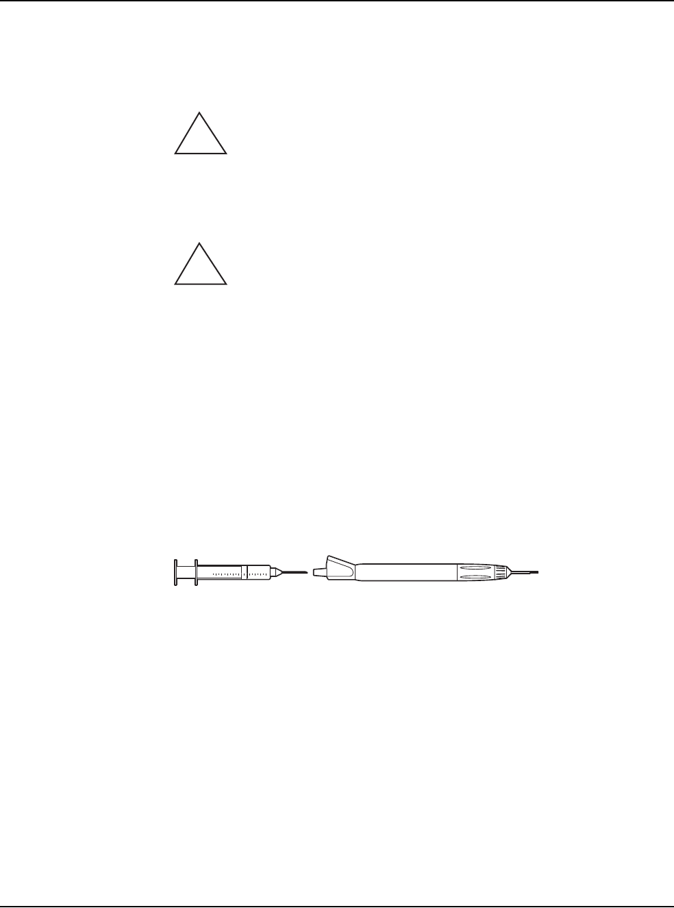
9 • Care and Cleaning
WHITESTAR SIGNATURE™ System Rx Only – Z370147 Rev. C 1108 9-3
5. Aspirate sterile nonpyrogenic water through the phaco tip into a syringe; this
clears any debris from within the tip and prevents clogging of the suction port.
6. Gently wipe the power cable of the handpiece with gauze soaked in distilled
water.
WARNING: Improper/inadequate cleaning may result in particulate
matter adhering to the instrument and exfoliation of particles into the surgical field.
In addition, the function and life expectancy of the phaco handpiece can become
compromised.
CAUTION: DO NOT CLEAN THE PHACO HANDPIECE WITH
ANY TYPE OF ULTRASONIC CLEANING DEVICE; THE CLEANING
DEVICE CAN DAMAGE THE PIEZOELECTRIC CRYSTALS.
Irrigation/Aspiration Handpiece
1. Back-flush the IA handpieces immediately at the end of the procedure.
Use a 10cc syringe with sterile nonpyrogenic water and flush the water from
the back of the handpiece through the tip. This process must be performed at
least two times through both the irrigation and aspiration channels.
Note: You can use other available AMO® products designed for this process
(IA Cleaning Kit, AMO Part No. OM05510114).
Figure 9.1 – I/A Handpiece Cleaning
2. Make sure IA handpieces are dry when they are stored.
Diathermy Handpiece
Clean the diathermy handpieces with the same procedures you use to clean other
ophthalmic instruments.
Note: Inspect the Diathermy, Vitrectomy and Phaco handpiece cables for possible
damage on a daily basis.
Vitrectomy Cutter
The vitrectomy cutter is a disposable, single-use instrument.
!
!

9 • Care and Cleaning
WHITESTAR SIGNATURE™ System Rx Only – Z370147 Rev. C 1108 9-4
Sterilization
Procedures AMO recommends that you follow the sterilization procedures outlined in this
section to maximize the life of your System instruments.
All parts must be cleaned thoroughly prior to sterilization, and all sterilization
equipment must be validated prior to use.
CAUTION: DO NOT STERILIZE THE HANDPIECES PRIOR TO
PERFORMING THE CLEANING PROCEDURES DESCRIBED EARLIER
IN THIS SECTION.
THE STORAGE CASES PROVIDED CANNOT BE PLACED IN AN
AUTOCLAVE.
The following sterilization techniques, times, and temperatures must be used in
order to ensure consistent product performance:
Gravity Displacement Sterilization – A type of sterilizer in which incoming steam
displaces the residual air through a port or drain usually in or near the bottom of the
sterilizer chamber. Typical operating temperatures are 121 to 123°C (250 to 254°F)
and 132 to 135°C (270 to 275°F).
Prevacuum Sterilization – A type of sterilizer which relies on one or more pressure
and vacuum excursions at the beginning or end of the cycle.
This method of operation usually results in shorter cycle times because of the rapid
removal of air from the chamber and the load by the vacuum system, the usually
higher operating temperature (132 to 135°C / 270 to 275°F; 141 to 144°C / 285 to
290°F), and the shorter exposure time for porous loads.
Note: The cycle times require the product to be wrapped. In an emergency
situation only Flash Sterilization in accordance with ANSI/AAMI
ST79:2006 Comprehensive guide to steam sterilization and sterility
assurance in health care facilities can be used. The parameters for mixed
porous and nonporous items must be used.
CAUTION: GAS STERILIZATION IS NOT RECOMMENDED.
Cooling is not necessary prior to reassembly; however, caution must be used to
prevent burns. Follow the handpiece assembly instructions.
!
!

9 • Care and Cleaning
WHITESTAR SIGNATURE™ System Rx Only – Z370147 Rev. C 1108 9-5
WARNING: Sterility assurance is the responsibility of the user. All non-
sterile accessories must be sterilized prior to use. In addition, AMO recommends a
terminal sterilization cycle in the autoclave after the final case of the day. This
cycle must include a drying cycle to remove moisture from the tubing and
handpieces for storage.
Devices undergoing sterilization must be thoroughly cleaned to minimize
bio-burden. Validation of the sterilization vessel and the sterilization cycle is the
responsibility of the user.
1. After sterilization, store the instruments in a safe, clean environment. Keep the
instruments dry and free of dust. Make sure that the handpiece nose cone tips
are adequately protected during storage.
2. Do not wind the phaco handpiece cord too tight. Handle the cord as you would
a fiber optic cable. Follow the natural curve of the cord and wind only as tight
as the natural curve of the cord (approximately 6 inch coiled cord diameter).
WARNING: Handle the phaco handpiece with extreme care. The
piezoelectric crystal in the handpiece is very sensitive to shock. If the handpiece is
dropped, it is possible that the handpiece might not function correctly. If this
happens, contact AMO for repair information or replacement.
WHITESTAR
SIGNATURE™
System Cleaning and
Care
1. Turn the power switch on the back of the System Off before you unplug the
system from the wall outlet.
2. At the end of the day, thoroughly wipe down the system, cart, power pole and
footpedal using a cloth dampened with a germicidal detergent and sterile
nonpyrogenic water. Be careful not to saturate any part of the system or the
footpedal with liquid. Excessive liquid can damage the System electronics.
3. Do not push or pull on the system components.
4. AMO recommends that you leave the footpedal and power cords connected to
the system to prevent loss and unnecessary wear on the electrical connectors.
5. Although the footpedal is water-resistant, make sure that the footpedal is kept
as dry as possible.
6. Place the Advanced Control Pedal (dual linear) in the storage recess at the
bottom of the console so that the footpedal batteries can charge. You can attach
the footpedal cable to the console to charge the batteries.
7. Place the wireless remote control in the storage recess on the top of the console
so that the Wireless Remote Control batteries can charge.
!
!

WHITESTAR SIGNATURE™ System Rx Only – Z370147 Rev. C 1108 10-1
Error Message Display
Fuse Replacement Procedure
Wireless Foot Pedal Battery Replacement Procedure
Most Common User-Correctable Problems
Status, Warning and Error Messages
System Operation (Error) Messages
Troubleshooting
10 ERROR MESSAGES
TROUBLESHOOTING AND
DIAGNOSTICS

10 • Error Messages Troubleshooting and Diagnostics
WHITESTAR SIGNATURE™ System Rx Only – Z370147 Rev. C 1108 10-2
Error Message
Display The red Error Messages are shown at the top of the screen. Press the Help button to
open the corrective action for that error. When the error is corrected, press OK to
clear the error message from the screen. If the error message is cleared but not
corrected, the error message is generated again.
The yellow Alerts are shown at the top of the screen. The alert does not need to be
cleared as an error message. An alert, for example, can be: Remote Control Battery
power level is 10 – 25% of maximum. The battery needs to be charged.
WARNING: DO NOT try to replace the Wireless Remote Control
batteries. Call your AMO Technical Service representative to replace the batteries.
Fuse Replacement
Procedure If the System does not turn on when the power switch is turned On, and you have
confirmed that the power cord is properly connected and plugged in, check to see if
the fuse is bad.
Note: To prevent the risk of fire or damage to the instrument, replace the fuses
with the exact type and rating as indicated below (check the voltage sticker
on the back panel of System to confirm your system voltage):
Table 10.1 – Fuse Specifications
To replace the console fuses:
1. Unplug the System electrical power.
2. Unplug the power cord from the back panel.
3. Locate the fuse holder on the back panel of the System, as shown below.
4. Use a small screwdriver to gently pry open the cover and expose the fuse
holder.
5. Gently pry out the fuse holder.
6. Remove the bad fuse and replace the fuse with a new fuse (value and size
specified above).
7. Replace the fuse holder. Make sure that the arrows point to the right side of the
back panel. Tilt the fuse holder slightly to the right and push in.
8. Push the fuse holder cover up and in until the cover snaps closed.
9. Reconnect the power cord to the back panel.
10. Plug the System into an electrical receptacle (outlet).
!
Voltage Quantity Fuse
Specifications
Console 100/120/240 2 6.3A, 250V,
Bussman GDA
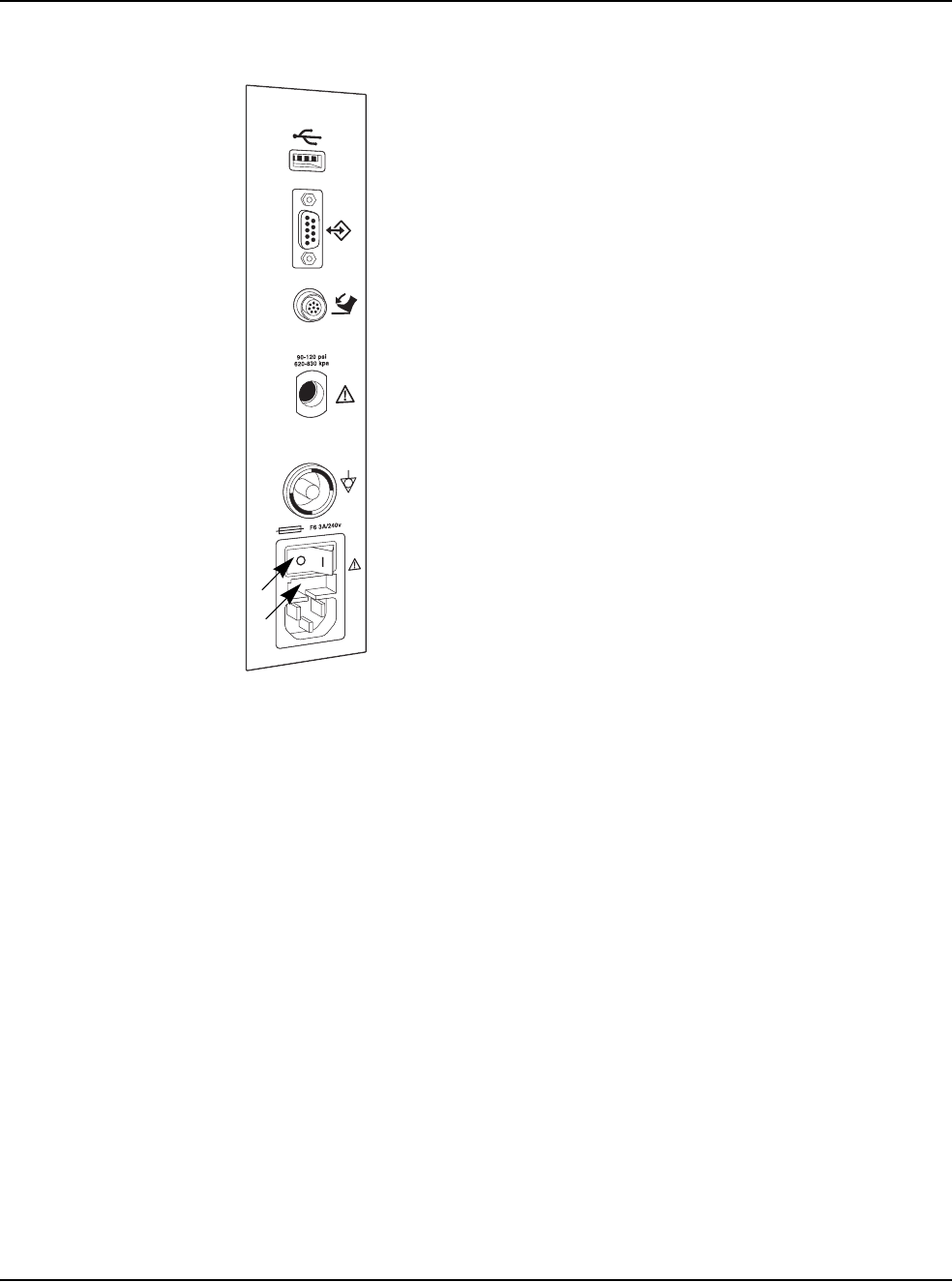
10 • Error Messages Troubleshooting and Diagnostics
WHITESTAR SIGNATURE™ System Rx Only – Z370147 Rev. C 1108 10-3
Figure 10.1 – Fuse Location
Wireless Foot Pedal
Battery Replacement
Procedure
Four AA size NiMH batteries provide power to the wireless foot pedal. You must
replace the batteries with the same size and type (NiMH) of batteries. If incorrect
batteries are used, the wrong batteries might cause damage to the foot pedal.
To replace the batteries in the foot pedal:
1. Remove the screws on the battery cover. The battery cover is located on the
bottom of the foot pedal.
2. Remove the old batteries. Do not throw the batteries in to the garbage. Use the
proper disposal method for the batteries.
3. Insert the new batteries. Make sure that the batteries are inserted correctly.
4. Replace the battery cover and tighten all of the screws.
1. Power Switch 2. Fuse Holder
1
2
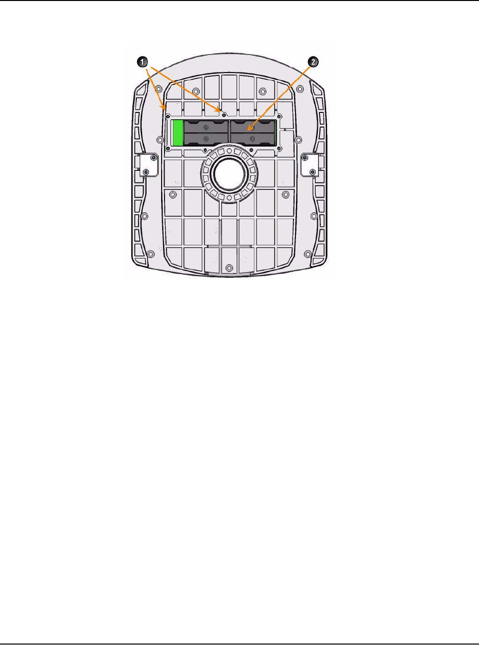
10 • Error Messages Troubleshooting and Diagnostics
WHITESTAR SIGNATURE™ System Rx Only – Z370147 Rev. C 1108 10-4
Figure 10.2 – Battery Location for the Wireless Foot Pedal
1. Battery Cover Screws (7) 2. NiMH Batteries

10 • Error Messages Troubleshooting and Diagnostics
WHITESTAR SIGNATURE™ System Rx Only – Z370147 Rev. C 1108 10-5
Most Common
User-Correctable
Problems
Use the information in this section if you are not successful with the System
Check-out. Consult this section to resolve the problem before you call AMO for
technical service.
Before you call AMO for service:
• Make sure that the System is plugged in to a power recptacle.
• Make sure that there is electrical power to the receptacle.
• If there is no phacoemulsification, make sure that the phaco needle is tight on the
handpiece.
• If there is no phacoemulsification, make sure that the phaco needle is compatible
with the handpiece (for example, non-AMO® phaco needle on an AMO®
handpiece).
• If there is no phacoemulsification, confirm that phaco needle/handpiece was not
damaged by dropping or misuse.
• If no irrigation occurs, shake the drip chamber to confirm that the ball or valve
moves freely. If there is no rattle sound, replace the drip chamber with another
disposable tubing pack.
Status, Warning and
Error Messages The System shows Status, Warning and Error Messages on the monitor.
The message can show possible solutions or recommendations to clear the error.
The messages can indicate the available options if a component or subsystem fails.
The messages are listed in the following pages with the corrective actions to be
taken to clear the error.
Recycle Power as a Corrective Action means that you turn the System Off (through
the normal shut down procedure), wait a few seconds, and then turn the System On.
If an error cannot be corrected, document the error message before you call AMO
for technical service. Technical Service needs to know the error message to
diagnose and correct the error.
System Operation
(Error) Messages Table 10.2 – Fluidic Controller Error Messages
Error
Number Message Probable Cause Corrective Action
14 Vacuum Parameter Check
Failure. Hardware failure or
program error. Select Next Case.
15 Flow Parameter Error Hardware failure or
program error. Select Next Case.
16 FP Yaw Parameter Error Hardware failure or
program error. Select Next Case.

10 • Error Messages Troubleshooting and Diagnostics
WHITESTAR SIGNATURE™ System Rx Only – Z370147 Rev. C 1108 10-6
17 FP Pitch Parameter Error Hardware failure or
program error. Select Next Case.
18 IV Check Error Hardware failure or
program error. Select Next Case.
19 Vit Cutter Check Error Hardware failure or
program error. Select Next Case.
101 Fluidics communication
error. Invalid data from the IH
or communication errors. Select Next Case.
102 Fluidics write error. Microcontroller SPI, SPI
Bus, EEPROM, or ADC
is faulty.
Cycle power.
103 Fluidics read error. Microcontroller SPI, SPI
Bus, EEPROM, or ADC
is faulty.
Cycle power.
104 Fluidics Reservoir Vacuum
Level Error. External air pressure low.
Venturi muffler clogged.
External air valve
clogged.
External air leak.
Venturi vacuum path leak.
Vacuum sensor not
calibrated or faulty.
Reprime the System.
105 Fluidics Reservoir Leak. Venturi vacuum path leak Reprime the System.
106 Fluidics Tank Vacuum
Level Error. Reservoir vacuum is low.
Tank vacuum path leak.
Vacuum sensor not
calibrated or faulty.
Vacuum regulator not
calibrated or faulty.
Vacuum regulator drive
circuit failure.
Reprime the System.
107 Fluidics Tank Leak. Tank vacuum path leak. Reprime the System.
Error
Number Message Probable Cause Corrective Action

10 • Error Messages Troubleshooting and Diagnostics
WHITESTAR SIGNATURE™ System Rx Only – Z370147 Rev. C 1108 10-7
108 Fluidics Pack Vacuum
Level Error. Reservoir vacuum is low.
Pack vacuum path leak.
Vacuum sensor not
calibrated or faulty.
Vacuum regulator not
calibrated or faulty.
Vacuum regulator drive
circuit failure.
Reprime the System.
109 Fluidics Pack Leak. Pack leak. Reprime the System.
110 Fluidics RAM error. Bad Microcontroller. Cycle power.
111 Fluidics ROM error. Bad Microcontroller. Cycle power.
112 Fluidics Master
Communication error. Instrument Host
malfunction.
Bad microcontroller.
Cycle power.
113 Drain Pump Fault. Droplets, bubbles, or fog
on chamber walls.
Bad fluid level sensor(s).
Bad cable.
Fluid level sensor drive
circuits faulty.
Drain pump drive circuit
fault.
Check the chamber and the
bag for over-inflation.
Select Next Case.
114 Fluidics DAC Fault. Circuit failure (I2C bus,
DAC, or micro). Reprime the System.
115 Fluidics Evacuation
Vacuum Level Error. Reservoir vacuum is low
Evacuation vacuum path
leak
Vacuum sensor not
calibrated or faulty
Vacuum regulator not
calibrated or faulty
Vacuum regulator drive
circuit failure
Reprime the System.
116 Fluidics Evacuation Leak. Evacuation path leak. Reprime the System.
Error
Number Message Probable Cause Corrective Action

10 • Error Messages Troubleshooting and Diagnostics
WHITESTAR SIGNATURE™ System Rx Only – Z370147 Rev. C 1108 10-8
117 Fluidics Fluid Level Sense
Error. Droplets, bubbles, or fog
on chamber walls.
Bad fluid level sensor(s).
Bad cable.
Fluid level sensor drive
circuits faulty.
Check the chamber and the
bag for over-inflation.
Select Next Case.
118 Fluidics Irrigation Valve
error. Valve failure.
Drive circuit failure.
Cycle power.
119 Fluidics Pinch Valve error. Valve failure.
Drive circuit failure.
Cycle power.
120 Fluidics Silicone Extraction
Valve Fault Valve failure.
Drive Circuit failure.
Disable Venturi or select
Next Case.
121 Fluidics Pack Alignment
Valve Fault. Pump failure.
Drive circuit failure.
Reinsert the pack and
reprime.
122 Fluidics Dump Valve Fault. Valve failure.
Drive circuit failure.
Disable Venturi or select
Next Case.
123 Fluidics Venturi Valve
Fault. Valve failure.
Drive circuit failure.
Disconnect compressed air.
Reprime the system.
124 Fluidics Rotary Vane Fault. Pump failure.
Drive circuit failure.
Connect compressed air.
Reprime the system.
125 Fluidics Pack Valve error. Valve failure.
Drive circuit failure.
Cycle power.
127 Fluidics Valve Vent error. Irrigation blocked. 1. End the current Case.
2. Start a New Case.
3. Reprime the System.
4. Turn the system off, wait a
few seconds, then turn the
system on.
5. Install a new tubing
cassette
6. If the error does not clear or
if the error continues to
occur, document the Error
Message and contact AMO
for technical service.
128 Fluidics Pack Loading
error. Pack not properly seated. Reload the tubing cassette.
Reprime.
129 Fluidics Proportional Valve
Fault. Valve failure.
Drive circuit failure.
Disconnect compressed air.
Reprime the system.
Error
Number Message Probable Cause Corrective Action

10 • Error Messages Troubleshooting and Diagnostics
WHITESTAR SIGNATURE™ System Rx Only – Z370147 Rev. C 1108 10-9
130 Fluidics Encoder error. Pack loading problem.
Encoder is faulty.
Decoder circuit is faulty.
Stepper driver circuit is
faulty.
Reload the tubing cassette.
Select Next Case.
131 Fluidics Mode error. Instrument Host
malfunction.
Bad SSC Board.
Bad footpedal.
Cycle power.
132 Fluidics VAC regulator
current is too high or too
low.
Vacuum regulator faulty.
Drive circuit faulty.
Disable Venturi or select
Next Case.
133 Fluidics strain gauge ADC
error. ADC is faulty. Cycle power.
134 Fluidics Drain Pump
Rotational Error. Pack loading problem.
Encoder is faulty.
Decoder circuit is faulty.
Stepper driver circuit is
faulty.
Insert Fusion™ Pack or
select Next Case.
Reprime the system.
135 Low external air pressure. Leak in external air
supply path.
Pressure regulator set too
low.
Pressure sensor faulty.
Reinsert the pack and
reprime.
Check the external air
supply.
136 Fluidics VAC Regulator
Vent Fault. Pinch valve is blocked. Disable Venturi or select
Next Case.
137 Footpedal error. Bad footpedal or user
depressing footpedal. Release the footpedal.
Disconnect and reconnect
footpedal.
Cycle power and retry.
138 Tank fluid level has reached
the top sensor. Drain pump cannot keep
up with the input of fluid. Please wait for the tank to
drain
144 Fluidics Vacuum Senors
Disagree Error. Leak in vacuum path
Vacuum sensor faulty.
Reinsert the pack and
reprime.
147 Reservoir vacuum is too
low. Target vacuum cannot
be reached.
Leak
Vacuum regulator faulty
Drive circuit faulty
Select Next Case.
Reprime the system.
Error
Number Message Probable Cause Corrective Action

10 • Error Messages Troubleshooting and Diagnostics
WHITESTAR SIGNATURE™ System Rx Only – Z370147 Rev. C 1108 10-10
148 Pressure to pack capture
mechanism is less than 60
psi.
Leak Reinsert the pack and
reprime.
149 Unloaded strain gauge
reading is too high or too
low.
Pack not loaded correctly. Reinsert the pack and
reprime.
201 Phaco Communication
error. Bad data sent from host. Retune or cycle power.
202 Phaco power error. Hardware failure (phaco
driver). Retune or cycle power.
203 Phaco handpiece error. Bad handpiece. Retune or cycle power.
Replace the phaco handpiece.
204 Phaco handpiece error. Wire in handpiece broken. Retune or cycle power.
Replace the phaco handpiece.
207 Incompatible Handpiece
Error. Incompatible handpiece. 1. Turn off Ellips™
Technology.
2. Attach the Ellips™
handpiece.
3. Tune the handpiece.
210 Phaco RAM error. Chip is bad. Cycle power.
211 Phaco ROM error. Bad 196 processor. Cycle power.
212 Phaco controller timeout. Host stopped writing to
the Phaco controller. Cycle power.
281 Phaco communication
error. Software bug or Hardware
failure. Cycle power.
282 Phaco error. Bad handpiece. Check handpiece and retune.
283 Phaco error. Driver failure. Check handpiece and retune.
Replace the handpiece and
tune.
284 Phaco power supply error. Bad Power Supply. Cycle power or call service.
285 Check for loose handpiece
and retune. Tip is loose. Check for loose handpiece
tip and retune.
Replace the handpiece and
tune.
286 Phaco handpiece impedance
error. Bad handpiece. Check handpiece and retune.
Replace the handpiece and
tune.
Error
Number Message Probable Cause Corrective Action

10 • Error Messages Troubleshooting and Diagnostics
WHITESTAR SIGNATURE™ System Rx Only – Z370147 Rev. C 1108 10-11
288 Diathermy error. DIA subsystem issue. Check handpiece.
Select Next Case or cycle
power.
290 Footpedal error. Bad footpedal or user
pressing the footswitch. Check footpedal. Cycle
power.
291 Phaco Diathermy power
supply error. Software or hardware
failure. Cycle power.
301 Pneumatics RAM error. Microcontroller failure. Cycle power.
302 Pneumatics ROM error. Microcontroller failure. Cycle power.
303 Pneumatics Master
communication error. Watchdog event.
PC104 Bus failure.
Micro failure.
CPLD failure.
Cycle power.
307 Pneumatics communication
error. Invalid data received by
the IH or communication
error.
Cycle power.
308 External air pressure high/
low. Valve failure.
Drive circuit failure.
Check compressed air
supply.
Select Next Case.
309 Piston pump pressure high/
low. Pump failure.
Drive circuit failure.
Select Next Case.
310 Vit selector valve pressure
high/low. VIT Selector Valve
failure.
Drive circuit failure.
Select Next Case.
311 Dump valve pressure high/
low. VIT Dump Valve failure.
Drive circuit failure.
Select Next Case.
312 Cut valve pressure high/
low. VIT Cut Valve failure.
Drive circuit failure.
Select Next Case.
322 Pneumatics system pressure
too low. V1 External Air valve not
open.
Piston Pump not working.
System leak.
Dump valve not closing.
Vitrectomy Cut valve
always on.
Select Next Case.
Error
Number Message Probable Cause Corrective Action

10 • Error Messages Troubleshooting and Diagnostics
WHITESTAR SIGNATURE™ System Rx Only – Z370147 Rev. C 1108 10-12
323 Pneumatics system pressure
too low. PP1 Piston Pump not
working.
Piston Pump not working.
System leak.
Dump valve not closing.
Vitrectomy Cut valve
always on.
Select Next Case.
327 Pneumatics system pressure
too low at the high cut rates. PP1 Piston Pump not
working.
Piston Pump not working.
System leak.
Dump valve not closing.
Vitrectomy Cut valve
always on.
Selector valve is not
changing.
Select Next Case.
336 Pneumatics system pressure
too low at the low cut rates. PP1 Piston Pump not
working.
Piston Pump not working.
System leak.
Dump valve not closing.
Vitrectomy Cut valve
always on.
Selector valve is not
changing.
Select Next Case.
353 IH to GUI Communication
Timed Out. Software error or
hardware error. Select Next Case.
360 IH Fluidics – read error. Communication error. Cycle power.
361 IH Fluidics – write error. Communication error. Cycle power.
362 IH Fluidics – Comm. error. Communication error. Cycle power.
370 IH Phaco read error. Communication error. Cycle power.
371 IH Phaco write error. Communication error. Cycle power.
372 Bad Phaco long pulse. Communication error. Check program setting.
Cycle power.
373 IH Invalid Phaco burst
setting. Communication error. Check program. Cycle
power.
374 Handpiece removed during
Phaco. No handpiece is
connected. 1. Attach a handpiece.
2. Tune the handpiece.
Error
Number Message Probable Cause Corrective Action

10 • Error Messages Troubleshooting and Diagnostics
WHITESTAR SIGNATURE™ System Rx Only – Z370147 Rev. C 1108 10-13
375 Incompatible HP. Attempted to use Ellips™
Phaco settings with a
WHITESTAR®
handpiece.
1. Turn off Ellips™
Technology.
2. Attach the Ellips™
handpiece.
3. Tune the handpiece.
380 IH Pneumatics – read error. Communication error. Cycle power.
381 IH Pneumatics – write
error. Communication error. Cycle power.
390 IH Diag read error. Communication error. Cycle power.
391 IH Diag write error. Communication error. Cycle power.
416 Footpedal communication
error. Could not open port.
Footpedal not responding.
Reconnect footpedal.
418 Footpedal compatibility
error. New footpedal firmware. Replace footpedal.
501 Prime excessive vacuum
error. Communication error. Check the tubing cassette.
Reload or replace the tubing
cassette.
Reprime.
502 Prime low bottle height
error. Bottle not at the proper
height. Increase bottle height and
reprime.
503 Prime low vacuum error. Hardware failure. Check the tubing cassette.
Reload or replace the tubing
cassette.
Reprime.
507 Prime EQ pressure error. Hardware failure. Reprime.
508 Prime low venturi vacuum
error. Hardware failure. Reprime.
511 IV Pole communications
error. Communication error. Reprime the system.
512 IV Pole communications
error. Communication error. Reprime the system.
513 IV Pole communications
error. Communication error. Reprime the system.
514 IV Pole error. Communication error. Reprime the system.
Error
Number Message Probable Cause Corrective Action

10 • Error Messages Troubleshooting and Diagnostics
WHITESTAR SIGNATURE™ System Rx Only – Z370147 Rev. C 1108 10-14
515 IV Pole calibration error. Communication error. Reprime the system.
516 IV Pole communication
error. Communication error. Reprime the system.
517 IV Pole jammed. Jammed.
Motor failure.
A “Short” in the motor
wires.
Obstruction is not
allowing the pole to move
Check for obstructions.
Reprime the system.
601 Tune excessive vacuum
error. Hardware failure. Check the tubing and the
connections to the handpiece.
Retune.
605 Tune no handpiece error. Hardware failure. Insert handpiece and retune.
2000 DLL CRC Error DLL checksum does not
match config.dat. Cycle power.
2001 CRC Error STR checksum does not
match config.dat. Cycle power.
2002 Database Self Test Error Database file checksum
does not match config.dat. Cycle power.
2003 Error updating database
file. Error when database was
saved. Cycle power.
2004 Error adding language. Error during the Install
Language session. Cycle power.
2005 Error reading USB memory
stick. Error during an Import or
Export session. Cycle power.
2006 Error loading DLL. Cannot find or load a DLL
file. Cycle power.
2007 Record file save error. Error when Record
database file was saved. Cycle power.
2008 Error reading Record file. Cannot read Record
database file. Cycle power.
2010 IH Communication timed
out. No communication with
the IH. Cycle power.
Error
Number Message Probable Cause Corrective Action

10 • Error Messages Troubleshooting and Diagnostics
WHITESTAR SIGNATURE™ System Rx Only – Z370147 Rev. C 1108 10-15
Troubleshooting Table 10.3 – Troubleshooting – General
2011 Error retrieving version
strings from IH. Cannot not retrieve the IH
version numbers. Cycle power.
2012 IH timeout error. No communication with
IH. Cycle power.
2014 IH Selftest error. Cannot get Selftest status
from the IH. Cycle power.
Error
Number Message Probable Cause Corrective Action
General
Problem Corrective Action
The System does not come
on when the power switch
is turned on.
1. Turn the power switch Off.
2. Confirm that the power cord is connected to the console back panel.
3. Confirm that the power cord is plugged into the electrical receptacle or
another power source.
4. Confirm that there is electrical power to the wall receptacle or power
source.
5. Turn the system On.
6. If the system still does not come on, turn the power Off. Check for bad
fuses and replace the fuse if necessary.
7. Contact AMO for Technical Service.

10 • Error Messages Troubleshooting and Diagnostics
WHITESTAR SIGNATURE™ System Rx Only – Z370147 Rev. C 1108 10-16
The wireless remote control
does not pair. 1. Make sure that you are pairing only one remote. If you try to pair more
than one remote at the same time, the pairing fails.
2. Only pair the remote with one console at a time. Do not press the
pairing key sequence on multiple remote controls as this causes the pairing
to fail.
3. Do not have any other Bluetooth® devices in the same area as the
remote and the console (other remote controls, dual linear foot pedals, cell
phones, or headsets, for example) as the pairing operation will fail. The
software only detects a maximum of nine (9) devices any more than nine
and the pairing fails.
4. Check to see if the remote control is in “Sleep” mode. If the remote is
in “Sleep” mode, press the Backlight button on the remote. Complete the
UP, DOWN, RIGHT, LEFT, RELOAD key sequence to pair the remote.
Note: Always press the Backlight button before you pair the remote.
5. The remote control can only be paired with one console at a time.
Make sure that the remote has not been paired with another console. You
must:
• Unpair the remote from the console.
• Shut down the console.
• Pair the remote with the new console. Make sure this console is at
least 40 meters away from the first console.
6. The remote cannot be paired with another console after that remote has
been paired. (You cannot pair one remote with two (2) consoles.)
• Unpair the remote from the console.
• Move the first remote out of range from the console.
• Wait for the first remote to go into “Sleep” mode.
• Pair the new remote.
7. Make sure that the batteries are fully charged before you pair the
remote with the console. Low batteries can cause pairing failures.
8. Charge the batteries if pairing has failed after several attempts.
9. When the batteries are charging (the remote is in the charge cradle):
• The Bluetooth® is turned off
• The remote cannot be used
• Pairing cannot be performed
General
Problem Corrective Action

10 • Error Messages Troubleshooting and Diagnostics
WHITESTAR SIGNATURE™ System Rx Only – Z370147 Rev. C 1108 10-17
Dual Linear Foot Pedal
does not pair.(Advanced
Control Pedal)
1. Make sure that the foot pedal is not paired with another console.
2. Do not have any other Bluetooth® devices in the same area as the foot
pedal and the console (other remote controls, dual linear foot pedals, cell
phones, or headsets, for example) as the pairing operation will fail. The
software only detects a maximum of nine (9) devices any more than nine
and the pairing fails.
3. Make sure that the batteries are fully charged before you pair the foot
pedal with the console. Low batteries can cause pairing failures.
4. Charge the batteries if pairing has failed after several attempts.
5. When the batteries are charging (the foot pedal is in the charge cradle):
• The Bluetooth® is turned off
• The foot pedal cannot be used
• Pairing cannot be performed
The footpedal is not
operating properly. 1. Go to the Diagnostics section and perform a Footpedal Test.
2. Confirm the footpedal cord is connected at the back of the console.
3. Confirm the footpedal is paired to the System, for the Advanced
Control Pedal (dual linear) only.
4. Perform a Foot Pedal Calibration, for the Advanced Control Pedal
(dual linear) only.
5. Replace the wireless footpedal batteries, Advanced Control Pedal
(dual linear) only.
The Programmable IV Pole
does not respond. 1. The pole might have reached maximum or minimum height.
2. Attempt a Programmable IV Pole height adjustment with the touch
screen, remote, or the up and down switch on the side of the system.
The Touch Screen does not
respond. Perform the Touch Screen Calibration procedure as described in
Diagnostics.
Priming Errors. 1. Check the tubing pack loading, including reloading the tubing cassette.
2. Verify that there are no kinks, clogs, or loose fittings.
3. Replace the handpiece and the tip and prime.
4. Replace the tubing cassette.
5. Check the test chamber for proper installation and leaks.
6. Contact AMO Technical Service to check the vacuum.
General
Problem Corrective Action

10 • Error Messages Troubleshooting and Diagnostics
WHITESTAR SIGNATURE™ System Rx Only – Z370147 Rev. C 1108 10-18
Table 10.4 – Troubleshooting – Irrigation
Irrigation
Problem Corrective Action
No irrigation flow. 1. Make sure the appropriate mode is selected on the screen.
2. Check for kinks in the irrigation tubing.
3. Check the tubing connection to the handpiece.
4. Tap the drip chamber to make sure the valve operates properly.
5. Check the bottle height.
6. Press the footpedal to Position 1 and check for flow.
7. Listen for the irrigation pinch valve in the tubing manifold area to
confirm that the valve operates when the footpedal is pressed.
8. If there is still no flow, replace the tubing cassette.
Reduced/insufficient
irrigation flow. 1. Check for kinks in the tubing or leaks in the tubing or the handpiece.
2. Check the bottle height.
3. Check the tubing connections.
4. Check for a pinched irrigation sleeve at the incision.
Irrigation flow continues
even when footpedal is Off
(Position 0).
1. Check that the footpedal is not obstructed and not stuck in P 1.
2. Check the footpedal operation.
3. Verify that Continuous Irrigation is not active.
Anterior chamber is too
shallow or too deep. 1. Check the bottle height.
2. Too shallow, check for a pinched irrigation sleeve at the incision.
3. Check the pump speed (flow rate).
4. Check that the irrigation tubing is not obstructed.
5. Make sure Irrigation and Aspiration are balanced.
Using large amounts of
fluid. 1. Check the bottle height.
2. Check the incision size.
3. Check the flow rate (pump speed too high).
4. Check that no fluid enters the collection bag when you do not use
irrigation.
5. Reseat or replace the tubing.

10 • Error Messages Troubleshooting and Diagnostics
WHITESTAR SIGNATURE™ System Rx Only – Z370147 Rev. C 1108 10-19
Table 10.5 – Troubleshooting – Aspiration
Aspiration
Problem Corrective Action
No aspiration. 1. Make sure the appropriate mode is selected on the screen.
2. Check for kinks or clogs in the tubing.
3. Check the tubing connection to the handpiece.
4. Make sure that the handpiece is not clogged.
5. Press the footpedal to Position 2 and check the pump function.
Poor aspiration. 1. Check the flow rate.
2. Check the footpedal operation.
3. Check for kinks or clogs in the tubing.
4. Make sure that the handpiece is not clogged.
5. Check the tubing connection to the handpiece.
6. Check the IA handpiece o-rings for excessive wear. Replace the
o-rings, if needed.
Not building vacuum.
Pump does not turn.
1. Check the programming. If the surgeon is in “linear vacuum” as
opposed to “linear aspiration”, the footpedal must be pressed through
Position 2 for the vacuum to reach the preset maximum.
2. Make sure the footpedal is pressed.
3. Check the tubing connection to the handpiece.
4. Check for air in the irrigation and aspiration tubing.
5. Check the system vacuum settings.
6. Replace the tubing cassette
7. Run IA Prime.
8. Check the flow rate.
Chamber shallowing or
partially collapses. 1. Check the bottle height and the handpieces for correct position.
2. Check the flow rate setting.
3. Check the tubing fittings to the handpiece.
4. Check for kinks in the tubing.
5. Remove the handpiece and perform the test chamber test to make sure
the handpiece is balanced.
6. Make sure Irrigation and Aspiration are balanced.

10 • Error Messages Troubleshooting and Diagnostics
WHITESTAR SIGNATURE™ System Rx Only – Z370147 Rev. C 1108 10-20
Table 10.6 – Troubleshooting – Phacoemulsification
Table 10.7 – Troubleshooting – Diathermy
Phacoemulsification
Problem Corrective Action
No phacoemulsification. 1. Make sure that the PHACO mode is selected on the touch screen.
2. Make sure that the System is Primed and Tuned.
3. Check the footpedal operation.
4. Make sure that the phaco handpiece cord is properly connected to the
phaco receptacle on the front of the system.
5. Check the Phaco Power setting.
6. Make sure that the phaco tip is tight on the handpiece.
7. Check to make sure that the phaco tip is not damaged.
8. If the tip is damaged, replace the tip with a new tip and retune.
Poor or intermittent
phacoemulsification. 1. Check all of the corrective steps above for “No Phacoemulsification”.
2. Remove the phaco tip and then replace the tip. Make sure the tip is
tight on the handpiece.
3. Check the Phaco Power delivery setting for both unoccluded and
occluded (if applicable) settings.
4. Tune the phaco handpiece.
Diathermy
Problem Corrective Action
No diathermy or poor
diathermy. 1. Make sure that the Diathermy mode is selected on the touch screen.
2. Check the footpedal operation.
3. Check the Diathermy Power setting.
4. Check the diathermy cord for a secure connection to the forceps and to
the diathermy receptacles on the system.
5. Make sure that the diathermy cord connections are dry.
6. Try to use diathermy starting at a low power setting and gradually
increase the power.
7. Replace the diathermy cord.
8. Replace the diathermy handpiece.
No sound when using
diathermy. 1. Make sure the Volume Setting is set at 6 or greater in Settings.
2. Check for sounds when you push any touch screen or remote buttons.
3. Check for an audible confirmation upon completion of system start-up
test (at power up).
4. Perform the Sound Test on the Diagnostics screen.

10 • Error Messages Troubleshooting and Diagnostics
WHITESTAR SIGNATURE™ System Rx Only – Z370147 Rev. C 1108 10-21
Table 10.8 – Troubleshooting – Vitrectomy
Vitrectomy
Problem Corrective Action
No vitrectomy cutting or
poor cutting. 1. Make sure that the Vitrectomy mode is selected on the touch screen.
2. Verify that the surgeon is in footpedal Position 3, if IAC step
vitrectomy is programmed. If ICA is programmed, verify the footpedal is
in Position 2.
3. Check the footpedal operation.
4. Check the tubing connections to the vitrectomy cutter.
5. Check the vitrectomy tubing connection to the front panel receptacle
on the system.
6. Check the Vitrectomy Rate (CPM) setting on the touch screen. Lower
the CPM, if necessary.
7. Check that irrigation and aspiration are working correctly.
8. Verify that the cutter blade moves.
9. Replace the vitrectomy cutter and try again.


11 • Warranty and Maintenance
WHITESTAR SIGNATURE™ System Rx Only – Z370147 Rev. C 1108 11-2
Warranty Statement AMO warrants for a period of two years (24 months) from the date of installation of
the WHITESTAR SIGNATURE™ System console, footpedal, wireless remote
control, programmable power pole and the phaco handpiece to be free from defects
in materials and workmanship when properly installed, maintained, and used for
the intended purpose.
MISUSE AND MISHANDLING ARE NOT COVERED UNDER WARRANTY.
AMO’s sole obligation is to repair or replace, at AMO’s option, the defective
part(s).
The Irrigation/Aspiration Handpiece Set, Diathermy Forceps and Diathermy Cord
are warranted for ninety (90) days.
This warranty applies only to the original purchaser/user of the device and only so
long as the equipment is used in the country to which it was originally shipped by
AMO.
THIS WARRANTY IS IN LIEU OF ALL OTHER WARRANTIES, EXPRESSED
OR IMPLIED, INCLUDING WITHOUT LIMITATION THE WARRANTIES OF
MERCHANTABILITY OR FITNESS FOR A PARTICULAR PURPOSE. IN NO
EVENT SHALL AMO BE LIABLE TO THE PURCHASER FOR
CONSEQUENTIAL DAMAGES.
Extended Warranty
Extended Warranty Contracts (excluding the phaco handpiece) are available.
Contact AMO for information on the availability of an Extended Warranty
Contract.
Note: If outside the United States, contact your local AMO office or
representative for warranty information.
Maintenance
User maintenance of the WHITESTAR SIGNATURE™ System is limited to those
adjustments and corrective actions given in the Error Messages and
Troubleshooting, and Diagnostics sections of this manual. There are no user
serviceable components within the machine and you must not attempt to access the
internal components. Any attempt to do so will void the warranty.
Routine or periodic maintenance of the WHITESTAR SIGNATURE™ System by
an AMO representative is recommended at least annually. AMO recommends the
measurement of PE resistance and leakage current according to IEC 601-1 every
two years.
If a problem continues following setup, check-out and troubleshooting as per the
procedures given in this manual, contact AMO for corrective action (1-877-AMO-
4LIFE in USA 1-877-266-4543). Please contact your local AMO office or
representative for region-specific phone numbers.

WHITESTAR SIGNATURE™ System Rx Only – Z370147 Rev. C 1108 12-1
Physical Specifications
Environmental Specifications
Electrical Specifications
Diathermy Specifications
Irrigation and Aspiration Specifications
Phacoemulsification Specifications
Vitrectomy Specifications
Diathermy Power Graphs
Diathermy Power versus Load Impedance
Phaco Power Graphs
12 SPECIFICATIONS

12 • Specifications
WHITESTAR SIGNATURE™ System Rx Only – Z370147 Rev. C 1108 12-2
Physical
Specifications Table 12.1 – System Physical Specifications
English /
U.S. Metric:
WHITESTAR SIGNATURE™ System Console:
Console Dimensions (with
display) Width 24 inches 61 cm
Depth 24 inches 61 cm
Height 54 inches 137 cm
Power Cord Length 20 feet 6 meters
Electrical Enclosure Current
Leakage IEC 60601-1
compliance
UL 60601-1
Weight (including IV pole) 195 pounds 88.5 kg
Footpedal:
Single Linear
Dimensions Width 12 inches 31 cm
Length 10.5 inches 27 cm
Height 5.5 inches 14 cm
Weight 10.0 pounds 4.5 kg
Advanced Control Pedal
(Dual Linear)
Dimensions Width 10.5 inches 27 cm
Length 14 inches 36 cm
Height 5.5 inches 14 cm
Weight 15 pounds 7 Kg
Cord Length 11.8 feet 36 cm
Power IV Pole:
Maximum Travel 41 inches 107 cm
Velocity 2.4 inches/sec 6 cm/sec.
Maximum Lift Weight 2.43 pounds 1.1 kg
Wireless Remote Control
Width 5 inches 13 cm
Length 5 inches 13 cm
Height 1.5 inches 4 cm
Weight 2.0 pounds .9 kg

12 • Specifications
WHITESTAR SIGNATURE™ System Rx Only – Z370147 Rev. C 1108 12-3
Environmental
Specifications Table 12.2 – Environmental Specifications
Electrical
Specifications Table 12.3 – Electrical Specifications
Diathermy
Specifications Table 12.4 – Diathermy Specifications
Irrigation and
Aspiration
Specifications
Table 12.5 – Irrigation and Aspiration Specifications
Environmental
Specifications Operating Temperature
Humidity
10 to 40°C
Up to 95% RH,
non-condensing
Storage/Transportation
Conditions Storage Temperature
Humidity
-20 to 60°C
Up to 95% RH,
non-condensing
Voltage Frequency Rated Power Fuse Rating Enclosure
Current Leakage
System 100/120/240
Vac 50/60 Hz 750 VA 6.3A, 250V,
Bussman
GDA
<500 uA
Diathermy
Specifications
Power Adjustment
Diathermy Power (maximum power
into rated load)
Diathermy Type
5 to 100%, in 5% increments
8.5 Watts into 350 ohms 386 KHz
Bipolar
IA Specifications
Peristaltic Pump Vacuum Level 0–650 mmHg in 5 mmHg increments
Pump Flow 0 to 60 cc/minute
Venturi Pump Vacuum Level 0-600 mmHg in 5 mmHg increments

12 • Specifications
WHITESTAR SIGNATURE™ System Rx Only – Z370147 Rev. C 1108 12-4
Phacoemulsification
Specifications Table 12.6 – Phacoemulsification Specifications
Vitrectomy
Specifications Table 12.7 – Vitrectomy Specifications
Phacoemulsification
Specifications Phaco Power 0 to 100%, in 5% increments
Peristaltic Pump Vacuum Level 0–650 mmHg in 5 mmHg increments
Pump Flow Rate 0 to 60 cc/minute
Venturi Pump Vacuum Level 0-600 mmHg in 5 mmHg increments
Vitrectomy Specifications
Peristaltic Pump Vacuum Level 0–650 mmHg in 5 mmHg increments
Pump Flow Rate 10 to 60 cc/minute, in 2 cc increments
Venturi Pump Vacuum Level 0-600 mmHg in 5 mmHg increments
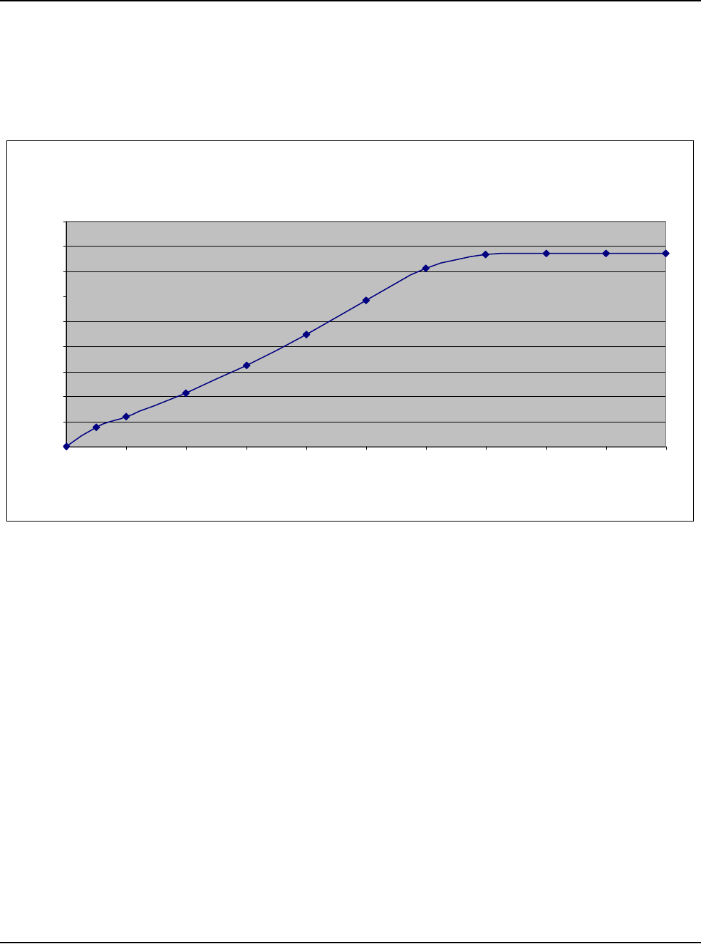
12 • Specifications
WHITESTAR SIGNATURE™ System Rx Only – Z370147 Rev. C 1108 12-5
Diathermy Power
Graphs
Table 12.8 – Diathermy Output Power (Typical) 50 Ohm
Diathermy Output Power (Typical)
50 Ohm
0
0.5
1
1.5
2
2.5
3
3.5
4
4.5
0 102030405060708090100
Control Panel Settings (%)
Output Power (Watts) +/- 20%

12 • Specifications
WHITESTAR SIGNATURE™ System Rx Only – Z370147 Rev. C 1108 12-6
Table 12.9 – Diathermy Output Power (Typical) 100 Ohm
Diathermy Output Power (Typical)
100 Ohm
0
1
2
3
4
5
6
7
0 102030405060708090100
Control Panel Settings (%)
Output Power (Watts) +/- 20%
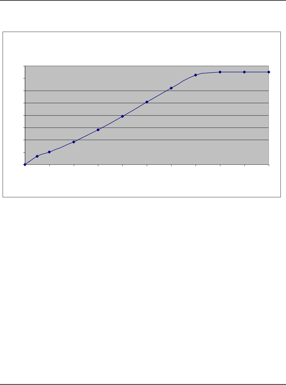
12 • Specifications
WHITESTAR SIGNATURE™ System Rx Only – Z370147 Rev. C 1108 12-7
Table 12.10 – Diathermy Output Power (Typical) 200 Ohm
Diathermy Output Power (Typical)
200 Ohm
0
1
2
3
4
5
6
7
8
0 102030405060708090100
Control Panel Settings (%)
Output Power (Watts) +/- 20
%
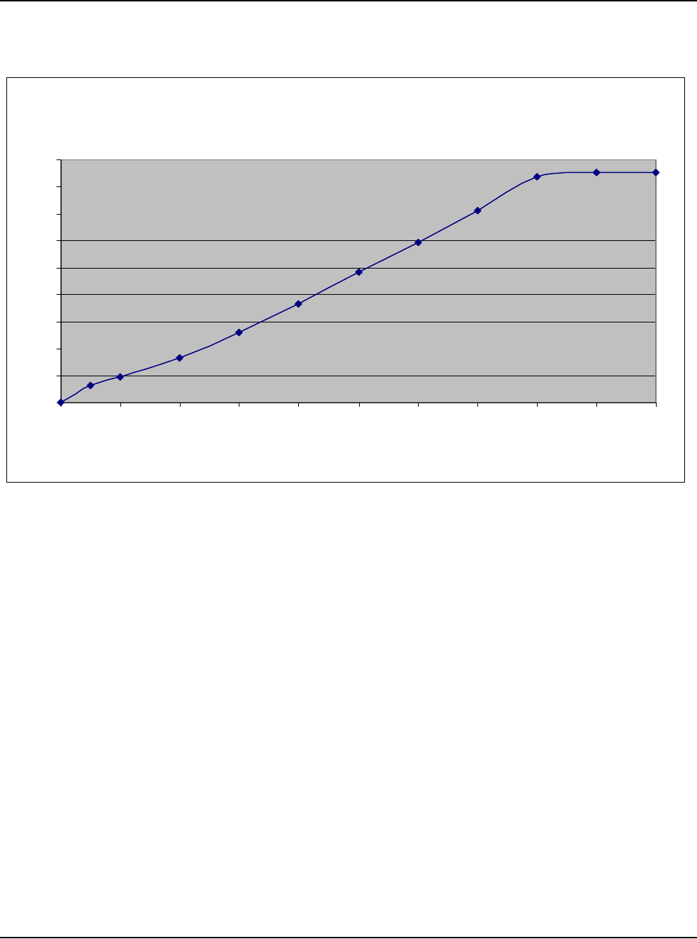
12 • Specifications
WHITESTAR SIGNATURE™ System Rx Only – Z370147 Rev. C 1108 12-8
Table 12.11 – Diathermy Output Power (Typical) 500 Ohm
Diathermy Output Power (Typical)
500 Ohm
0
1
2
3
4
5
6
7
8
9
0 102030405060708090100
Control Panel Settings (%)
Output Power (Watts) +/- 20
%
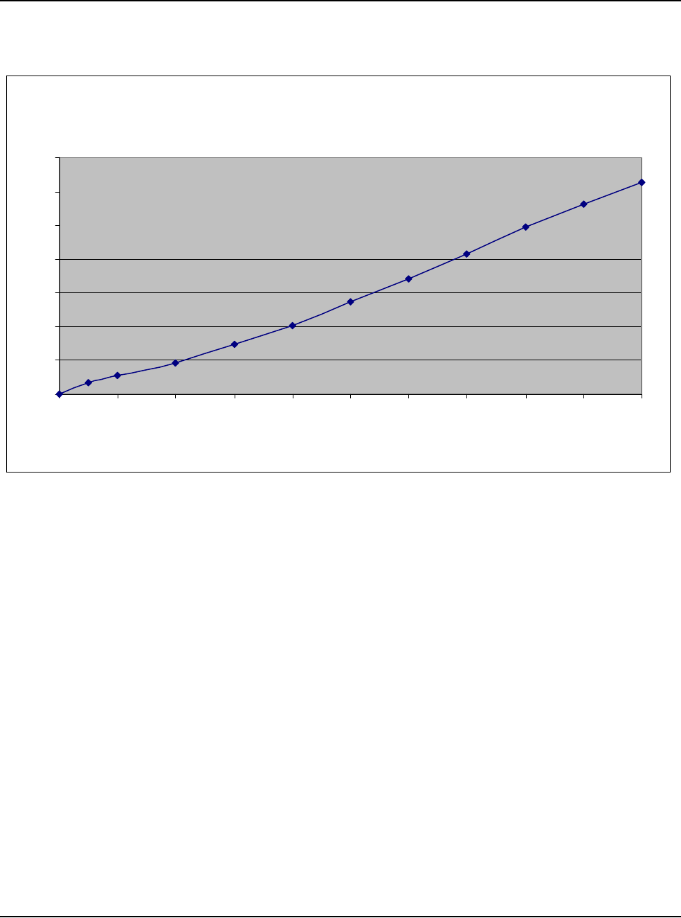
12 • Specifications
WHITESTAR SIGNATURE™ System Rx Only – Z370147 Rev. C 1108 12-9
Table 12.12 – Diathermy Output Power (Typical) 1000 Ohm
Diathermy Output Power (Typical)
1000 Ohm
0
1
2
3
4
5
6
7
0 102030405060708090100
Control Panel Settings (%)
Output Power (Watts) +/- 20%
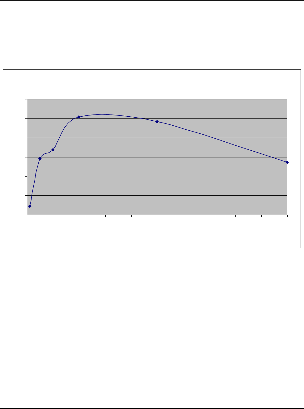
12 • Specifications
WHITESTAR SIGNATURE™ System Rx Only – Z370147 Rev. C 1108 12-10
Diathermy Power
versus Load
Impedance
Table 12.13 – Diathermy Output Power (50% Setting)
Diathermy Output Power (50% Setting)
0
1
2
3
4
5
6
0 100 200 300 400 500 600 700 800 900 1000
Load Resistance (Ohms)
Output Power (Watts) +/- 20%
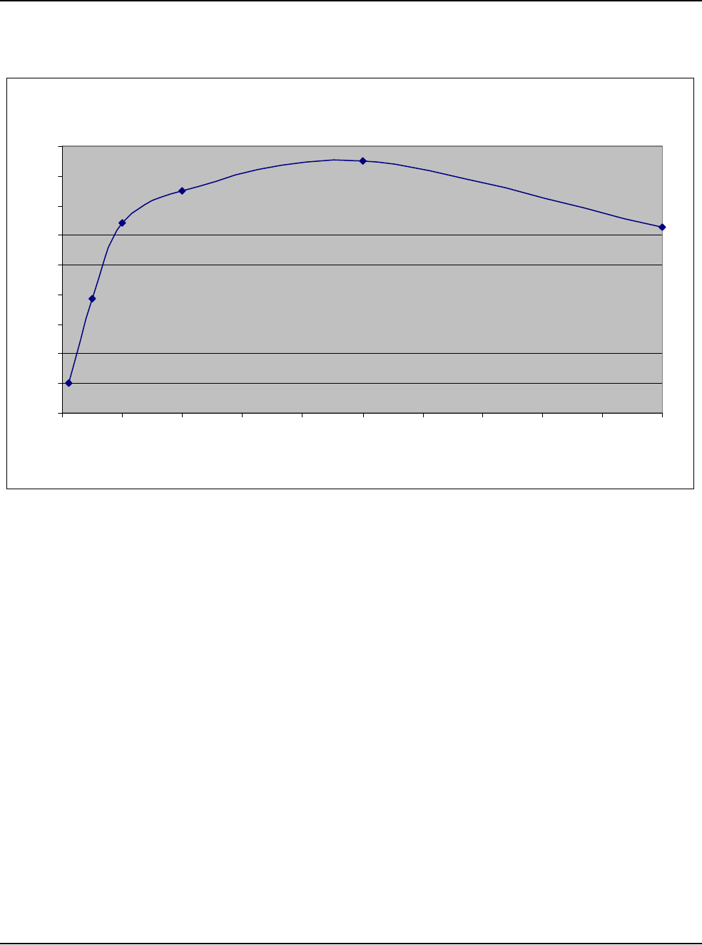
12 • Specifications
WHITESTAR SIGNATURE™ System Rx Only – Z370147 Rev. C 1108 12-11
Table 12.14 – Diathermy Output Power (100% Setting)
Diathermy Output Power (100% Setting)
0
1
2
3
4
5
6
7
8
9
0 100 200 300 400 500 600 700 800 900 1000
Load Resistance (Ohms)
Output Power (Watts) +/- 20%
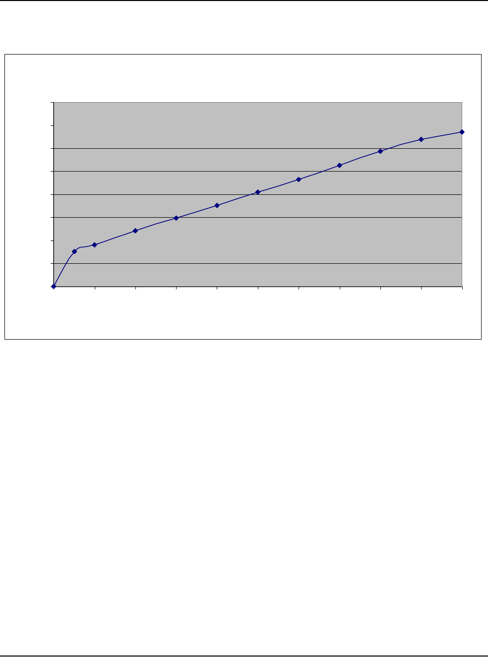
12 • Specifications
WHITESTAR SIGNATURE™ System Rx Only – Z370147 Rev. C 1108 12-12
Table 12.15 – Diathermy Voltage
Diathermy Voltage
0
20
40
60
80
100
120
140
160
0 102030405060708090100
Control Panel Settings (%)
Output Voltage (Volts) +/- 20%
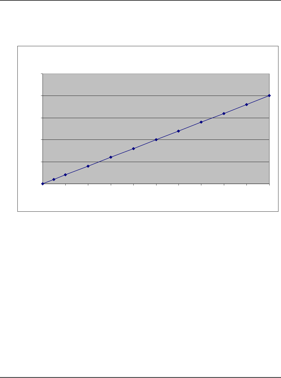
12 • Specifications
WHITESTAR SIGNATURE™ System Rx Only – Z370147 Rev. C 1108 12-13
Phaco Power
Graphs
Table 12.16 – Longitudinal Phaco Power
Phaco Power (Longitudinal)
0
5
10
15
20
25
0 102030405060708090100
Control Panel Settings (%)
Output Power (Watts) +/- 20%

12 • Specifications
WHITESTAR SIGNATURE™ System Rx Only – Z370147 Rev. C 1108 12-14
Table 12.17 – Ellips™ Phaco Power
Ellips™ Phaco Power
0
5
10
15
20
25
0 102030405060708090100
Control Panel Settings (%)
Output Power (Watts) +/- 20%
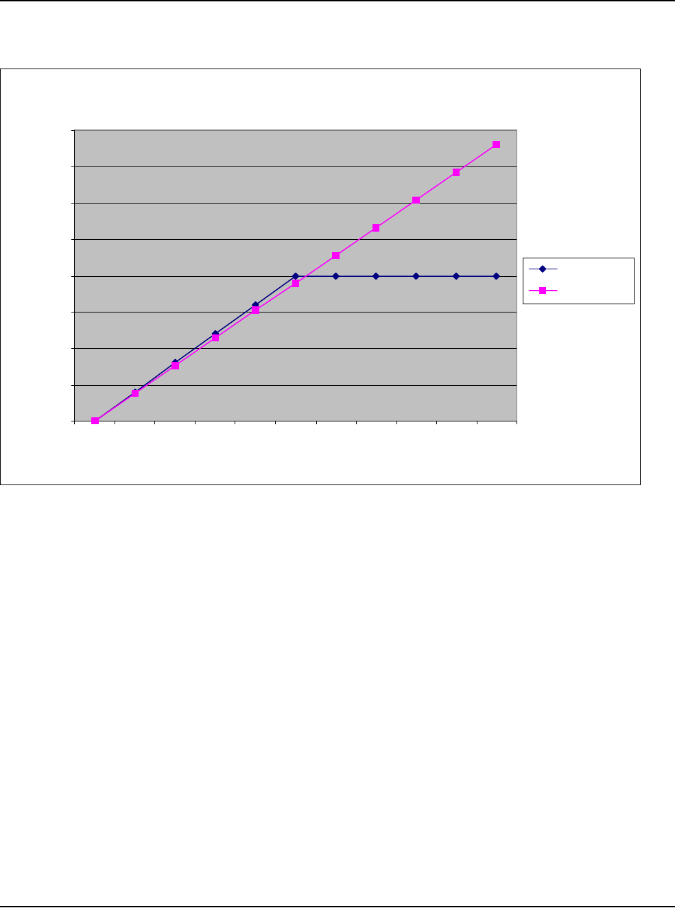
12 • Specifications
WHITESTAR SIGNATURE™ System Rx Only – Z370147 Rev. C 1108 12-15
Table 12.18 – Ellips™ Phaco Power and Longitudinal Phaco Power
Power Output (Watts)
0.00
5.00
10.00
15.00
20.00
25.00
30.00
35.00
40.00
0% 10% 20% 30% 40% 50% 60% 70% 80% 90% 100%
Displayed % Power
Watts
Ellips™ Phaco
Longitudinal
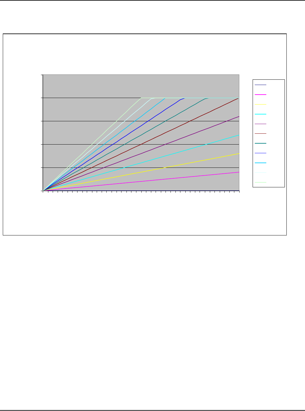
12 • Specifications
WHITESTAR SIGNATURE™ System Rx Only – Z370147 Rev. C 1108 12-16
Table 12.19 – Ellips™ Phaco Power Linear Mode
Ellips™ Power (in Linear Mode) Depending Upon User Defined
Max Power Setting
0.00
5.00
10.00
15.00
20.00
25.00
0.00%
10.00%
20.00%
30.00%
40.00%
50.00%
60.00%
70.00%
80.00%
90.00%
100.00%
Footpedal P3% Depression
Delivered Power (Watts)
0%
10%
20%
30%
40%
50%
60%
70%
80%
90%
100%


13 • Accessories and Parts Reordering
WHITESTAR SIGNATURE™ System Rx Only – Z370147 Rev. C 1108 13-2
Table 13.1 – WHITESTAR SIGNATURE™ System Part Number
List of Accessories
with Part Numbers The following table is a list of accessories that you can use to reorder parts for your
WHITESTAR SIGNATURE™ System. Your AMO representative can advise you
of recommended inventory levels based on the volume of phacoemulsification
procedures done in your facility. All of the items listed below are ordered through
your AMO representative or directly through AMO Customer Service.
Table 13.2 – Accessories and Parts List
Name Description Part No.
WHITESTAR SIGNATURE™
Console An ophthalmic microsurgical system. NGP680300
System Accessories Description Part No.
Phaco Handpiece AMO® Phaco Handpiece SOV680290
WHITESTAR® Phaco Handpiece,
Coaxial
690697
Ellips™ Phaco Handpiece 690858
19 Gauge LAMINAR™ Flow Phaco Tip,
0° Round Tip OPOR0019L
19 Gauge LAMINAR™ Flow Phaco Tip,
15° Round Tip OPOD1519L
19 Gauge LAMINAR™ Flow Phaco Tip,
30° Round Tip OPOD3019L
19 Gauge LAMINAR™ Flow Phaco Tip,
45° Round Tip OPOD4519L
Disposable 20 Gauge LAMINAR™
Flow Phaco Tip, 0° Round Tip OPOD0020L
Disposable 20 Gauge LAMINAR™
Flow Phaco Tip, 15° Round Tip OPOD1520L
Disposable 20 Gauge LAMINAR™
Flow Phaco Tip, 30° Round Tip OPOD3020L
Disposable 20 Gauge LAMINAR™
Flow Phaco Tip, 45° Round Tip OPOD4520L
Disposable LAMINAR™ Flow Phaco
Tip, 19 Gauge, 30° Curved OPOCR3019L
Disposable LAMINAR™ Flow Phaco
Tip, 20 Gauge, 30° Curved OPOCR3020L
19 Gauge LAMINAR™ Flow Irrigation
Sleeve and Test Chamber OPOS19L
Disposable 20 Gauge LAMINAR™ Flow
Infusion Sleeve and Test Chamber OPOD20L

13 • Accessories and Parts Reordering
WHITESTAR SIGNATURE™ System Rx Only – Z370147 Rev. C 1108 13-3
LAMINAR™ Flow Tip Wrench OPOMTWL
SOLO™ I/A Handpiece, 20 Ga., Curved
Silicone Sleeve Tip OPOIA20CRV
SOLO™ I/A Handpiece, 20 Ga., 45°
Silicone Sleeve Tip OPOIA2045D
SOLO™ I/A Handpiece, 20 Ga., Straight
Silicone Sleeve Tip OPOIA20STR
SOLO™ I/A Handpiece Kit OPOIA20KIT
I/A Handpiece PHACOFIT™ Titanium Handle OM055002
PHACOFIT™ I/A Tip Curved .5 mm Port OM05510110
PHACOFIT™ O-Ring's I/A Tip (5PK) OM05510112
PHACOFIT™ Titanium, Multi-Tip Set OM05510113
PHACOFIT™ Cleaning/Flushing Kit OM05510114
PHACOFIT™ Tip, Luer Adapter
(Aspiration) OM05510115
PHACOFIT™ Tip, 45 Degree Silicone
(No Sleeve) OM05510116
PHACOFIT™ I/A Tip Straight .3MM
Port OM0551011
PHACOFIT™ I/A Tip Curved .3 mm Port OM0551012
PHACOFIT™ I/A Tip 45 Degree 0.3 mm
Port OM0551013
PHACOFIT™ I/A Tip 90 Degree 0.3 mm
Port OM0551014
PHACOFIT™ I/A Tip Binkhorst 0.3 mm
Port OM0551015
PHACOFIT™ I/A Tip Straight SI 0.3 mm
Port OM0551016
PHACOFIT™ I/A Luer Adapter, F/F OM0551017
PHACOFIT™ I/A Tip Curved, SI, .3 mm
Port OM0551018
PHACOFIT™ I/A Tip Straight .5MM
Port OM0551019
PHACOFIT™ Athlete I/A Tip Straight
Type OM0551020J
PHACOFIT™ Athlete I/A Tip 45 Degree
Type OM0551021J
DUET™ STARTER KIT, 20GA DUA02020
System Accessories Description Part No.

13 • Accessories and Parts Reordering
WHITESTAR SIGNATURE™ System Rx Only – Z370147 Rev. C 1108 13-4
DUET™ ASPIRATION HANDLE DU02100
DUET™ IRRIGATION HANDLE DU02200
DUET™ 20G CURVED IRRIGATOR
CLOSED END DU02301
DUET™ 20G CURVED ASPIRATION
.3MM PORT CAP POL DU02302
DUET™ 19G FINE IRRIGATING
CHOPPER DU02303
DUET™ 20G OLSON II IRRIGATING
CHOPPER DU02305
DUET™ MST Aguirre Duet Tip DU02325
DUET™ MST Fine/Nagahara Tip DU02335
Diathermy Handpiece Bipolar Cord with Fischer Connection K106075
Bipolar Forceps, Curved Iris 0.5 mm Tip K121085
18 Gauge Straight Diathermy Pencil,
reusable K147000
Vitrectomy Cutter 20 gauge Vitreous Cutter NGP0020
23 gauge Vitreous Cutter NGP0023
25 gauge Vitreous Cutter NGP0025
FUSION™ Tubing Pack Fusion™ Tubing Pack (disposable,
sterile) OPO70
Fusion™ Dual Pump Tubing Pack
(disposable, sterile) OPO71
Wireless Remote Control WHITESTAR SIGNATURE™ System
Remote Control NGP680135
Footpedal WHITESTAR SIGNATURE™ Foot
Pedal (Single Linear) NGP680701
Advanced Control Pedal for the
WHITESTAR SIGNATURE™
(Dual Linear)
NGP680702
Miscellaneous Power Cord, Hospital Grade, 20 ft., 6.1
meters 2410-0049-L
Footpedal Cable to WHITESTAR
SIGNATURE™ System 0100-0055
WHITESTAR SIGNATURE™ Dust
Cover 0100-0750
Sterilization Tray MSR309
WHITESTAR SIGNATURE™ System
Owner's Manual (English) NGP Z370147
System Accessories Description Part No.

13 • Accessories and Parts Reordering
WHITESTAR SIGNATURE™ System Rx Only – Z370147 Rev. C 1108 13-5
WHITESTAR SIGNATURE™ System
Owner's Manual (Chinese) NGP Z370161
WHITESTAR SIGNATURE™ System
Owner's Manual (Korean) NGP Z370163
WHITESTAR SIGNATURE™ System
Owner's Manual (Japanese) NGP Z370162
WHITESTAR SIGNATURE™ System
Owner's Manual (French) NGP Z370148
WHITESTAR SIGNATURE™ System
Owner's Manual (German) NGP Z370150
WHITESTAR SIGNATURE™ System
Owner's Manual (Swedish) NGP Z370157
WHITESTAR SIGNATURE™ System
Owner's Manual (Finnish) NGP Z370160
WHITESTAR SIGNATURE™ System
Owner's Manual (Portuguese) NGP Z370152
WHITESTAR SIGNATURE™ System
Owner's Manual (Italian) NGP Z370149
WHITESTAR SIGNATURE™ System
Owner's Manual (Spanish) NGP Z370151
WHITESTAR SIGNATURE™ System
Owner's Manual (Danish) NGP Z370158
WHITESTAR SIGNATURE™ System
Owner's Manual (Dutch) NGP Z370153
WHITESTAR SIGNATURE™ System
Owner's Manual (Greek) NGP Z370156
WHITESTAR SIGNATURE™ System
Owner's Manual (Norwegian) NGP Z370159
WHITESTAR SIGNATURE™ System
Owner's Manual (Polish) NGP Z370154
WHITESTAR SIGNATURE™ System
Owner's Manual (Russian) NGP Z370155
WHITESTAR SIGNATURE™ System
Owner's Manual CD, Multilingual NGP Z370164
System Accessories Description Part No.

WHITESTAR SIGNATURE™ System Rx Only – Z370147 Rev. C 1108 Glossary-1
GLOSSARY
Term Definition
Active Reflux Reflux that occurs in response to a user request (typically by way of
the footpedal).
Active State The state where the instrument responds to the footpedal in all zones.
All the surgical modes are operative.
Active Vacuum Vent The vacuum is relieved by a controlled reversal of the peristaltic
pump or by the vacuum regulator.
Advanced Control Pedal (Dual
Linear) A footpedal for the WHITESTAR SIGNATURE™
Phacoemulsification System that operates in two independent linear
movement planes (Pitch and Yaw). The two linear movement planes
provide proportional control of user-defined functions.
Anterior Chamber A fluid filled space inside the eye between the iris and the innermost
corneal surface.
Anterior Mode The Anterior function operating mode of the instrument.
Anterior Segment The front third of the globe; includes structures located between the
front surface of the cornea and the vitreous.
Aspiration Removal of fluid from the eye using the pumps.
Aspiration Line Fluids pathway within he handpiece that is utilized to extract fluid and
tissue from the eye.
Burst Mode One of the available options on the WHITESTAR SIGNATURE™
System for phaco power delivery. Characterized by short periods of
time where the power is turned on, interspersed with off times.
CASE ChAmber Stabilization Environment is an intelligent vacuum system
that monitors occlusions and adjusts the vacuum to prevent or reduce
post occlusion surge or chamber collapse.
Cassette The tubing packs that are installed on the system to connect the tubing
on the hand pieces to the vacuum and irrigation sources in the
instrument.
Compatible Surgeon Programs Programs that have the same Pack Type, Pump Type, and Infusion
method.
Continuous Phaco Power One of the available Phaco power delivery modes.

Glossary
WHITESTAR SIGNATURE™ System Rx Only – Z370147 Rev. C 1108 Glossary-2
Controller A processor or microcontroller that is programmed to fulfill a specific
task. It can be anything from a small 8-bit microprocessor to a PC-
compatible system. On the WHITESTAR SIGNATURE™ system,
the following controllers have been identified: GUI Host Processor,
Instrument Host Processor, Fluidics Controller, Phaco-Diathermy
(PD) Controller, Pneumatic Controller, Diagnostic Controller, IV
Pole Controller, Remote Controller, Touch Screen Controller,
Footpedal Controller, Footpedal Wireless Controller, Remote
Wireless Controller, and Sound Controller.
Continuous Burst Phaco Power One of the available Phaco power delivery modes.
Diathermy Method used to coagulate blood vessels during a cataract procedure
and to join together the conjunctiva at the end of a cataract procedure
using electrical current.
DLL Dynamic Link Library. A collection of software routines that can be
loaded and accessed at run time.
Ellips™ Technology A technology that provides both longitudinal and transverse
movement within the Ellips™ handpiece.
EMI Electromagnetic Interference. Emitted by electrical circuits carrying
rapidly changing signals, as a by-product of their normal operation,
and which causes unwanted signals (interference or noise) to be
induced in other circuits.
Evacuation The removal, by suction, of fluids from the eye cavity through a
phacoemulsification ultrasonic handpiece.
Extraction The process or act of pulling or drawing out fluids from the eye cavity
during Phacoemulsification surgery.
Fluidics The components and aspects of the system involving fluid;
specifically, irrigation, aspiration, vacuum, pressure and their
performance as interdependent systems.
FPn Foot Pedal zone position (0, 1, 2, or 3). The zone changes when the
footpedal is pressed.
FUSION™ The screen in which the Occlusion mode, CASE mode, and Actual
Maximum Vacuum settings can be modified.
FUSION™ Fluidics Pack
(OPO70) The fluidic tubing pack which interfaces only with the peristaltic
pump related components.
FUSION™ Dual Pump Pack
(OPO71) The FUSION™ dual pump fluidic tubing pack which interfaces with
both the peristaltic and the vacuum-based pump related components.
Gravity Infusion The bottle height-induced irrigation when the IV pole is positioned at
a specific height.
GUI Graphical User Interface. Used to reference the interface presented to
the user on a graphical screen.
High Power Pulse Phaco Power One of the available Phaco power delivery modes.
Term Definition

Glossary
WHITESTAR SIGNATURE™ System Rx Only – Z370147 Rev. C 1108 Glossary-3
IV Pole The programmable pole used to position the irrigation solution during
the phacoemulsification process.
I/A A general term for Irrigation/Aspiration, and a specific footpedal
configuration.
IAC A Vitrectomy mode that uses the Irrigation, Aspiration, and Cutting
sequences as the footpedal is pressed.
ICA A Vitrectomy mode that uses the Irrigation, Cutting, and Aspiration
sequences as the footpedal is pressed.
Irrigation Causing fluid to be moved into/toward the eye via the irrigation line.
Irrigation Line The fluid path within the handpiece that is used to allow the clean
balanced salt solution to travel from the bottle into the eye.
LCD The Liquid Crystal Display on the WHITESTAR SIGNATURE™
System.
Linear Variable Any switch on the footpedal that is used for Linear control. (Pitch or
Yaw.)
Long Pulse Phaco Power One of the available Phaco power delivery modes.
Low Power Pulse Phaco Power One of the available Phaco power delivery modes.
Max Vac (Maximum Vacuum) The value for a vacuum based fluidic is the lesser of 600 mmHg or
85% of the CASE Upper Threshold. The maximum value for a
peristaltic pump is 650 mmHg.
Motor Venting Used with both the FUSION™ Fluidics pack (OPO70) and the Dual
Linear (OPO71) pack. Driving the peristaltic pump in the reverse
direction to vent.
Multiple Burst Phaco Power One of the available Phaco power delivery modes.
NiMh Nickel-Metal Hydride. A type of rechargeable battery.
One-Touch CASE The ability to alter the CASE settings with a single press of a button.
The modes are +2, +1, Standard, -1, -2.
Operating Mode The current operating mode of the instrument. The modes are Phaco,
I/A, Vitrectomy, and Diathermy.
Pairing The process of matching two BlueTooth® Devices, the console and
the remote control or the console and the wireless foot pedal, so that
they can communicate with one another.
Pars Plana Incision A surgical cut into the eyeball that passes through the sclera and the
pars plana area of the cilary body, between the pars plans and the ora
serrata. Common site for instruments used for Vitrectomy procedures.
Passive Reflux A small reflux from the aspiration line that occurs automatically when
the system vents. Historically, this has occurred on AMO® systems
that utilize valve venting.
Peristaltic A flow based pump.
Term Definition

Glossary
WHITESTAR SIGNATURE™ System Rx Only – Z370147 Rev. C 1108 Glossary-4
Phacoemulsification / Phaco The term is abbreviated as Phaco. Phaco is a cataract extraction
technique originally developed by Dr. Charles Kelman. To use this
technique, a surgeon makes a small incision in the eye and emulsifies
the cataract with the help of a vibrating needle inserted through the
incision. The emulsified particles of the cataract are gently aspirated
through the needle while the surgeon continues to irrigate the eye's
chamber to maintain intraocular pressure (IOP).
Pitch The vertical travel of the footpedal.
Pneumatics Components and aspects of the system involving high and low
pressure and vacuum.
Post Occlusion Surge A result of rapidly changing pressures within the anterior chamber of
the eye. The fluid surge is caused when the Phaco Tip is blocked
during a procedure and is suddenly cleared. The surge can cause an
imbalance of fluids leaving the eye and potential damage to the eye
tissue.
Power Boost Mode An operating mode in which the yaw movement of the Advanced
Control Pedal (Dual Linear Footpedal) is utilized to provide a
temporary increase (Boost) in phaco power.
Primary Venting Mechanism A venting mechanism (valve, motor) selected by the host software as
the preferred means of performing venting.
Programming Mode (System
Configuration) When the system is not Primed/and not Tuned Phaco, I/A, and
Vitrectomy surgical modes are not available. However, the user can
program and update surgical and system settings.
Pump Ramp A characteristic of the peristaltic pump that determines the point at
which the pump speed is decreased in order to maintain a manageable
rate of vacuum rise.
Pulse Shape A feature of WHITESTAR® Technology which allows the user to
define a "kick" of increased power at the beginning of a
WHITESTAR® pulse over a range of Phaco power settings.
Reflux Fluid that is moved into/toward the eye via the aspiration port/line.
The reverse flow within the aspiration line that can be used to release
or dislodge unwanted material from the handpiece tip or to “tent” the
incision site to allow easier tip insertion. Reflux is not intended to
clear a clogged handpiece. However, reflux can be used to identify a
blockage.
Remote Control A user interface control for the GUI system through a wireless
connection. The Remote Control commands are interpreted to control
the GUI software.
Safe State A state where the Phaco, Vitrectomy, Diathermy, and fluidics
functions are disabled, with irrigation on and the fluid vented. The
instrument the footpedal is disabled. As a result, all of the surgical
modes become inoperable.
Term Definition

Glossary
WHITESTAR SIGNATURE™ System Rx Only – Z370147 Rev. C 1108 Glossary-5
Secondary Venting Mechanism A venting mechanism (valve, motor or vacuum regulator)
automatically used by the system to attempt venting if the primary
venting mechanism should fail.
Short Pulse Phaco Power One of the available Phaco power delivery modes.
Single Burst Phaco Power One of the available Phaco power delivery modes.
Single Linear Footpedal A footpedal with only one plane of travel allowing proportional
control of system parameters.
SubMode A submode is a defined set of parameters for the current mode. Most
operating modes have multiple submodes. For example, there are
three I/A submodes for Anterior surgery, each of which contains a set
of potentially different parameters for the I/A mode.
Surgical Media Center (SMC) An optional accessory product that can be connected to the
WHITESTAR SIGNATURE™ system to generate and record video
images of the surgery. The video images contain embedded
information about the instrument status and settings throughout the
surgical procedure.
System A hardware unit and associated peripherals including software
required to perform a specific function.
Tenting the Incision (Wound) Using reflux while inserting the handpiece into the eye. This
technique causes the incision (wound) to open slightly (tent), thus
making handpiece insertion easier.
Touch Screen The display surface of the Liquid Crystal Display (LCD) that
responds to touch.
Vacuum Boost Mode An operating mode in which the yaw movement of the Dual Linear
Footpedal is utilized to provide a temporary increase (Boost) in the
maximum vacuum.
Vacuum Regulator Venting Using the vacuum regulator in the WHITESTAR SIGNATURE™
system to vent the vacuum in the OPO71 vacuum tank. Used only
with the Venturi pump.
Valve Reflux The fluid flows back through the pinch valve.
Valve Vent The vacuum is vented through the aspiration line.
Valve Venting Used with OPO70 pack only. Manipulation of the fluidic connections
to cause fluid from the irrigation bottle to be directed toward the
aspiration port in order to vent. Typically this results in passive reflux.
Variable WS A mode where the user can define the WHITESTAR® Technology
delivery based on the footpedal position.
Venting Relieving vacuum in the aspiration tube. Typically venting is
performed when the Footpedal is moved from position 2 into position
1 or 0.
Venturi A vacuum based pump.
Term Definition

Glossary
WHITESTAR SIGNATURE™ System Rx Only – Z370147 Rev. C 1108 Glossary-6
Vitrectomy The removal of vitreous with a needle-like cutter that has fluid
injection and suction capabilities.
WHITESTAR® Technology A proprietary software technology that is used to deliver finely
modulated pulses of energy, interrupted by extremely brief cooling
periods.
Yaw The horizontal movement of the footpedal that works from either the
left or the right of the footpedal.
Yaw Threshold The programmed yaw movement that is allowed before the yaw
switch is activated on the footpedal.
Term Definition

WHITESTAR SIGNATURE™ System Rx Only – Z370147 Rev. C 1108 Index-1
A
Accessories 13-1
Add a Surgeon 6-3
Adjusting
Cut Rates 5-29
Flow Rate 5-28
Advanced Control Pedal
Does Not Pair 10-17
Dual Linear 1-4, 3-11, 3-22, 7-4, 9-5, 12-2
Modes
Vitrectomy 5-20
Pitch
Thresholds 5-31
VIT 5-32
Settings
Dual Linear 5-19
Wireless 3-22
Anterior chamber too deep 10-18
Anterior Segment
Settings 5-37
Surgery 3-15
Anterior Segment Surgery 5-1
Aspiration
Specifications 12-3
Troubleshooting 10-19
Aspiration Flow Rate 5-28
Aspiration Rate
Occlusion 5-45
PHACO 5-7
Vitrectomy 5-17
Assign Order 6-14
Autoclave 9-4
B
Backlight button 10-16
Balance
Irrigation/Aspiration 4-10
balanced salt solution 3-19
batteries
footpedal 3-22, 9-5
remote control 3-26
Battery
Location
Wireless Foot Pedal 10-4
Replacement
Wireless Foot Pedal 10-3
Begin Tune 4-9
blocked
aspiration port 5-47
Bluetooth® 10-16
Bluetooth® devices 10-17
Bottle Height
IA 5-25
PHACO 5-26
Vitrectomy 5-27
Burst 5-3
Bypass 4-7, 4-11
INDEX

Index
WHITESTAR SIGNATURE™ System Rx Only – Z370147 Rev. C 1108 Index-2
C
Calibration
Touch Screen 7-7
Wireless Foot Pedal 7-5
Care of the System 9-5
CASE 5-7
CASE Lower Threshold
PHACO 5-26
CASE Mode 5-41
PHACO 5-26
CASE ONE Touch 1-7, 5-43
CASE Upper Threshold
PHACO 5-26
CASE Vac
PHACO 5-26
CASE Vacuum 5-16
Cassette
Loading 3-18
Chamber partially collapses 10-19
Changing
Irrigation 3-3
Mode Parameters 4-12
charging the footpedal 9-5
Check-out 8-2
Irrigation/Aspiration 8-2
Phacoemulsification 8-2
Vitrectomy 8-3
Cleaning
Handpiece 9-2
System 9-5
Common Problems 10-5
Complete
Setup 3-19
Components 2-2
Configuration 4-12
Connecting Handpieces 3-3
Connections
Rear Panel 3-16
Console Dimensions 12-2
Continuous Burst 5-37
PHACO Power 5-40
Continuous Irrigation 1-5, 4-7, 5-6
Cup Fill 4-9
IA 5-25
PHACO 5-26
Continuous Phaco Power 5-38
Continuous Power 5-37
Controls
Screens 4-2
Copy a Program 6-10
Cup Fill 4-7, 4-9
Custom Duty Cycles 5-11
Cut Rate
Adjusting 5-29
Vitrectomy 5-17, 5-27
cuts per minute 5-29
Cutter
Vitrectomy 3-21
Cutting Rates
Vitrectomy 5-29
D
Database 4-2
Delete 6-13
Management 7-2
Program 6-14
Restore 6-13
Default Program 4-6, 5-21
Default Settings
Diathermy 5-24
Footpedal 5-23
Irrigation/Aspiration 5-25
PHACO 5-26
Sound 5-22
Vitrectomy 5-27
Delete
Database 6-13
Program 6-12, 6-13
Surgeon 6-11
DIA time 5-3
Diagnostics 4-2, 7-2, 10-1

Index
WHITESTAR SIGNATURE™ System Rx Only – Z370147 Rev. C 1108 Index-3
Diathermy 1-6, 3-4, 5-2
Default Settings 5-24
Forceps 3-21
Handpiece 9-3
Part Numbers 13-4
Output Power 12-10
Pencil Probe 3-21
Power 12-10
Power Graphs 12-5
Specifications 12-3
Troubleshooting 10-20
Using 5-3
Voltage 12-12
Dimensions 12-2
drainage bag 3-18
DT 5-3
Dual Linear
Advanced Control Pedal 1-4, 3-11, 3-22,
5-31, 7-4, 9-5, 12-2
Settings 5-19
Settings
Advanced Control Pedal 5-19
VIT Footpedal Settings 5-32
Dual Linear Foot Pedal does not pair 10-17
Dual Pump 1-5
Duty Cycles 5-9
PHACO 5-27
E
Edit
Program 6-9
Surgeon 6-5
Effective Phaco Time 5-35
Electrical
Specifications 12-3
Ellips™ 1-4
Handpiece 1-4, 3-17
Technology 5-48
End Case 4-2, 5-34
Environmental
Specifications 12-3
EPT 5-35
Equipment Operation 4-1
Error Message 10-2
Error Messages 10-5
F
failed to pair 10-16
Feedback
Footpedal 5-24
Flash Sterilization 9-4
Flow Rate
Adjusting 5-28
Fluidics 1-4
Error Messages 10-5
Mode
PHACO 5-26
Foot Pedal
Battery Replacement 10-3
Calibration 7-5
Pitch
Advanced Control Pedal 5-31
Pitch Thresholds
single linear 5-30
Settings
single linear 5-19
Single Linear 1-4
wireless 3-4
Footpedal 1-4, 3-22, 4-2
Advanced Control Pedal 3-11
charging 9-5
Dual Linear
Advanced Control 3-11
Feedback 5-24
Modes
Vitrectomy 5-20
Part Number 13-4
Pitch 3-23
Pitch Regions 5-24
Positions 3-23, 5-11
Settings 5-23, 5-30
Setup
Wireless 7-3
Single Linear 3-22
Specifications 12-2

Index
WHITESTAR SIGNATURE™ System Rx Only – Z370147 Rev. C 1108 Index-4
Summary
single linear 5-23
Switch Assignment 5-32
Threshold 5-24
Vitrectomy 5-17, 5-27
Wireless 1-4, 3-22
Forceps 11-2
Diathermy 3-21
Fuse
Location 10-3
Replacement 10-2
Fusion 5-15, 5-44
FUSION™ 2-4
FUSION™ Tubing Pack
Part Number 13-4
G
Gas Sterilization 5-28, 9-4
General
Troubleshooting 10-15
Graph
Phaco Power 12-13
Graphic User Interface 1-5
Graphs
Diathermy Power 12-5
Gravity Displacement Sterilization 9-4
GUI 1-5
H
Handpiece
Cleaning 9-2, 9-3
Connecting 3-3
IA 3-18
Phaco 3-20
Priming 4-8
Ultrasonic 3-3
Warranty 11-2
Help 10-2
High Power
Limit 5-14
Pulse 5-37
PHACO Power 5-39
I
IA Handpiece 3-18
Submodes 5-5
IAC 5-20
ICA 5-20
ICE Pulse Shaping
WHITESTAR® 5-14
Infusion Sleeve 2-4
Initial Mode 5-8, 5-24, 5-25, 5-28
Inspection Instructions 2-2
Install Tubing Cassette 4-6
Irrigation
Changing 3-3
Continuous 4-7, 5-6
flow does not stop 10-18
Inadequate 3-3
Specifications 12-3
Troubleshooting 10-18
Irrigation/Aspiration 1-7, 5-4
Balance 4-10
Check-out 8-2
Default Settings 5-25
IV Pole
does not work 10-17
Programmable 3-4, 3-25, 5-4
K
kick 5-14
L
LAMINAR™ Flow 3-18
Linear 5-2, 5-3, 5-28
Occluded Power 5-47
List of Accessories 13-1
Load
Impedance 12-10
Resistance 12-10
Locked Program 6-13
Logs 7-2

Index
WHITESTAR SIGNATURE™ System Rx Only – Z370147 Rev. C 1108 Index-5
Long Pulse
PHACO Power 5-38
Power 5-37
Rate
PHACO 5-26
Low batteries 10-16, 10-17
Low Power
Limit 5-14
Pulse 5-37
PHACO Power 5-39
Lower Threshold 5-16
M
Maintenance 4-2, 11-2
Touch Screen 7-7
Max Aspiration
IA 5-25
Rate
Occluded
PHACO 5-27
PHACO 5-26
Vitrectomy 5-27
Max Phaco Power
Occluded
PHACO 5-27
Unoccluded
PHACO 5-27
Max Power
Diathermy 5-24
Max Vacuum 5-9
IA 5-25
PHACO 5-26
Vitrectomy 5-27
maximum vacuum 5-15
Mayo Stand Drape 2-4
Messages
Error 10-2
Miscellaneous Part Numbers 13-4
Mode Programming 1-6
Modes
Changing Parameters 4-12
How to program 5-21
Monitor Drape 2-4
Multiple Burst
PHACO Power 5-39
Power 5-37
Multiple Mode Programming 1-6
N
NiMH 3-22, 10-3
No aspiration 10-19
No diathermy or poor diathermy 10-20
No irrigation flow 10-18
No phacoemulsification 10-20
No sound when using diathermy 10-20
No vacuum 10-19
No vitrectomy cutting 10-21
O
Occluded Aspiration Rate 5-44
Occluded Phaco 5-7
Occlusion
Aspiration Rate 5-45
Threshold 5-9
PHACO 5-26
Vacuum Threshold 5-45
Venting 5-47
OCCLUSION MODE™ Phaco
Settings 5-26, 5-41, 5-44
Off Time 5-27
On Time 5-27
ONE Touch
CASE 5-43
Operating Modes 1-6
Anterior Segment 5-1
Operating the Equipment 4-1
Output Power
Diathermy 12-10
Override Settings 5-40

Index
WHITESTAR SIGNATURE™ System Rx Only – Z370147 Rev. C 1108 Index-6
P
pairAdvanced Control Pedal 10-17
Dual Linear Foot Pedal 10-17
Wireless Remote Control 10-16
Pairing Instruction
Wireless Remote Control 7-6
Pairing Instructions
Wireless Foot Pedal 7-4
Panel 5-2, 5-3, 5-28
Occluded Power 5-47
Parameter Settings
WHITESTAR® Technology 5-10
Parameters
Programming 1-6
Part Numbers 13-2
Parts
Reordering 13-1
Passive Reflux 5-48
Pencil Probe
Diathermy 3-21
Percent Kick
High End of Range 5-14
Low End of Range 5-14
Peristaltic Pump 12-3
PHACO
Default Settings 5-26
Program 5-8
Submodes 5-7
Using 5-8
Phaco Handpiece 1-4, 3-4, 3-17, 3-20, 9-2
Part Numbers 13-2
PHACO Power 5-37
Phaco Power 5-7
Continuous 5-38
Graph 12-13
Phacoemulsification 1-2, 1-7, 3-3, 3-16, 5-6, 5-7,
8-3, 10-20, 12-4
Check-out 8-2
Specifications 12-4
Troubleshooting 10-20
Physical Specifications 12-2
PITCH 3-23
Pitch Regions
Footpedal 5-24
Poor aspiration 10-19
Poor phacoemulsification 10-20
Positions
Footpedal 3-23
Power
Continuous 5-37
Continuous Burst 5-37
Delivery
Diathermy 5-24
PHACO 5-26, 5-27
Failure 3-3
High Pulse 5-37
Long Pulse 5-37
Low Pulse 5-37
Multiple Burst 5-37
PHACO 5-7
Phaco 5-37
Short Pulse 5-37
Single Burst 5-37
Switch 10-5
Power Cord Length 12-2
pps 5-38
Precautions 8-2
Safety 3-2
Preferred Program 6-6
Prevacuum Sterilization 9-4
Prime
Bypass 4-7
Prime/Tune 1-5, 4-2, 4-7, 4-8, 4-9, 5-3, 8-2
Priming
Handpiece 4-8
Vitrectomy 4-11
Problems
Common 10-5

Index
WHITESTAR SIGNATURE™ System Rx Only – Z370147 Rev. C 1108 Index-7
Program 4-2
Assign Order 6-14
Configuration 5-21
Database 6-14
Defaults 5-21
Delete 6-12
Edit 6-9
Lock 6-13
Locked 6-13
Preferred 6-6
Programmable IV Pole 1-6, 3-4, 3-19, 3-25, 5-4
Specifications 12-2
Programming
Multiple Mode 1-6
PHACO 5-8
Programs
Select 4-4
Surgeon 6-1
Pulse Off Time 5-10
Pulse On time 5-10
Pulse Rate 5-10
Pulse Shaping 5-12
pulses per second 5-38
Pump not working 10-19
Pump Ramp
PHACO 5-26
Threshold
IA 5-25
R
Rear Panel 3-16
Recording Mode 3-28
Reduced/insufficient irrigation flow 10-18
Reflux 3-24
Passive 5-48
Remote Control 3-4
Wireless 3-26, 7-6
Remote Pair 7-6
Reordering
Parts 13-1
Replacing
Batteries 10-2, 10-3
Replacing the Fuse 10-2
Reset
Timers 4-10
Restore
Database 6-13
Restriction of Hazardous Substances 3-14
RoHS 3-14
S
Safety Precautions 3-2
Screens
Controls 4-2
Select Program 4-6
Selecting a Language 4-3
Self Test 4-4
Settings
Anterior Segment 5-37
Footpedal 5-30
How to program 5-21
Occlusion Mode 5-44, 5-47
OCCLUSION MODE™ Phaco 5-41
Override 5-40
Submode Parameters 5-4
Setup
Completion 3-19
Sequence 3-15
System 8-2
Wireless 7-6
Short Pulse
PHACO Power 5-38
Power 5-37
Rate
PHACO 5-26
Shutdown
Sequence 3-29
Side VIT 5-20
Side vitrectomy 5-20
Single Burst
PHACO Power 5-39
Power 5-37
Single Linear
Foot Pedal 1-4, 12-2
Settings 5-19
Pitch Thresholds 5-30

Index
WHITESTAR SIGNATURE™ System Rx Only – Z370147 Rev. C 1108 Index-8
Sleep Mode 10-16
SMC
Surgical Media Center 3-27
SOLO™ 3-18
Sounds 4-2
Default Settings 5-22
Specifications
Diathermy 12-3
Electrical 12-3
Environmental 12-3
Footpedal 12-2
Fuse 10-2
IA 12-3
IV Pole 12-2
Phacoemulsification 12-4
Physical 12-2
Vitrectomy 12-4
Start Vit Prime 8-3
Startup 4-4
Status 10-5
STD Surgeon 6-2
Sterilization 3-22, 9-4
Gas 9-4
Gravity Displacement 9-4
Prevacuum 9-4
Storage Conditions 12-3
Submode
Parameters 5-4
PHACO 5-7, 5-40
Submodes
IA 5-5
PHACO 5-7
Surgeon
Add 6-3
Copy 6-10
Delete 6-11
Edit 6-5
Select 6-1
STD 6-2
Surgeon/Program
Select 4-4
Surgeons and Programs 4-13
Surgical Media Center
SMC 3-27
Switch Assignment 5-30
Footpedal 5-32
Symbol Definitions 3-9
System
Check-out 8-2
Cleaning 9-5
Console 1-5
Default Settings 5-22
Description 1-2
Disposal 3-12
does not turn on 10-15
Self Test 4-4
Shutdown 3-29
Tests 7-2
Utilities 7-2
T
Technical Service 10-5
Technology
WHITESTAR® 5-9
Test Chamber 2-4, 13-2
Threshold
Vacuum 5-45
Timers
Reset 4-10
Touch Screen
Calibration 7-7
Does not respond 10-17
Using 4-12
Translucency 3-28
Troubleshooting 8-2, 10-1
Aspiration 10-19
Diathermy 10-20
General 10-15
Irrigation 10-18
Phacoemulsification 10-20
Vitrectomy 10-21
Tubing Cassette 2-4
Install 3-18, 4-6
Tune 4-7
Begin 4-9

Index
WHITESTAR SIGNATURE™ System Rx Only – Z370147 Rev. C 1108 Index-9
U
Ultrasonic (U/S) Time 5-35
Ultrasonic Handpiece 3-3
Unoccluded Phaco 5-7
Unpair 10-16
Up Time
PHACO 5-26
Threshold 5-16
Upper Threshold 5-16
Using
Diathermy 5-3
PHACO 5-8
too much fluid 10-18
Touch Screen 4-12
Vitrectomy 5-18
V
Vacuum 5-34
monitoring 5-15
PHACO 5-7
pressure 5-47
Rate
Linear 5-28
Panel 5-28
Vitrectomy 5-17
Variable WHITESTAR® Technology 5-11
Variable WS 5-11
Venting
Occlusion 5-47
Venturi pump 5-16
VIT Foot Pedal Settings
dual linear 5-32
Vitrectomy 3-4, 3-21, 5-17
Advanced Control Pedal (Dual Linear) Modes
5-20
Check-out 8-3
Cut Rate 5-29
Cutter 3-4
Default Settings 5-27
Footpedal Modes 5-20
Prime 4-11
Specifications 12-4
Troubleshooting 10-21
Using 5-18
VIT 1-7
Voltage
Diathermy 12-12
W
Wake-up 3-24
Warnings 3-2, 3-5
Warranty 11-1
Watts 12-5, 12-14
WHITESTAR
Decrement 5-32
Increment 5-32
WHITESTAR® ICE Technology 1-3
WHITESTAR® Technology 1-3, 5-9
Wireless Advanced Control Pedal 3-22
Wireless Foot Pedal 3-4
Battery Location 10-4
Calibration 7-5
Wireless Footpedal
Pairing 7-4
Setup 7-3
Wireless Remote Control 1-5, 3-4, 3-26
Part Number 13-4
Setup 7-6
wireless remote control does not pair 10-16
Y
Yaw 3-23