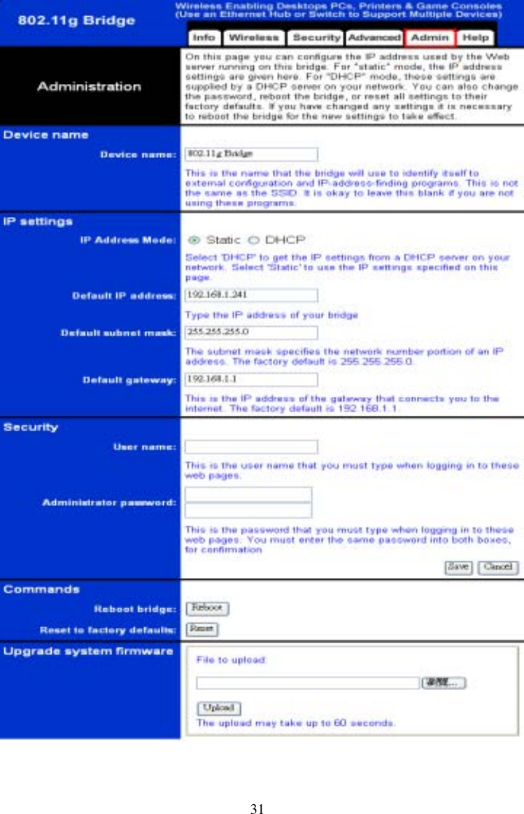
Abocom Systems AP900 802.11b+g Wireless AP(2.4GHz) User Manual

Abocom Systems Inc 802.11b+g Wireless AP(2.4GHz)

User Manual

       Wireless 802.11g   Access Point  User’s Manual
 Table of contents  INTRODUCTION.....................................................................................1 Features............................................................................................................... 1 LED Indicators................................................................................................... 2 Solid................................................................................................................. 2 Ports on the Rear Panel..................................................................................... 2 GETTING CONNECTED.........................................................................4 AP MODES:............................................................................................5 CONFIGURATION VIA WEB ..................................................................6 Login.................................................................................................................... 6 Info(Information)............................................................................................... 7 Assoc(Associations)—Only for Access Point mode......................................... 8 Wireless (Wireless Configuration)....................................................................9 Access (Access Control)-Only for Access Point mode................................... 11 Advanced (Advanced Wireless)...................................................................... 12 Security ............................................................................................................. 15 IP Addr (IP Address Settings) -Only for Access Point mode........................ 17 IP Address Mode............................................................................................ 17 Access point name ......................................................................................... 18 Admin (Administration).................................................................................. 19 Change password. .......................................................................................... 19 Reboot/Reset this device................................................................................ 19 Upgrade system firmware.............................................................................. 19 Help ................................................................................................................... 21
1 Introduction The Wireless 802.11g Access Point is a 54 Mbps Access Point (AP) that can also act as a Media Access Control (MAC) bridge between wired Local Area Networks, and one or more LAN wireless networks.    Placed anywhere along with an Ethernet LAN, the Wireless 802.11g Access Point allows up to 200 wireless stations within its area of coverage to access transparently to the corporate network. Features ♦  High speed for wireless LAN connection, 54 Mbps. ♦  Web browser-based configuration utility. ♦  Wireless security of 128-bit WEP Encryption/ MAC Address Filtering ♦  AP Visibility Modes ♦  Firmware upgrades ♦  Static IP Address or DHCP ♦  Automatic Device Discovery
2  LED Indicators LED Indicators on the Front Panel            Status LED Indicator Solid Dim/ Flashing Power  Glows when power is applied to this device, the LED turns solid yellow.   Dim when no power is applied.  Status  Normal  Flashing when upgrading firmware.  LAN-Link    Glows when Ethernet is connected.  Dim when no Ethernet is connected.  Flashing when this device is sending/receiving data LAN-100M  Glows for 100Mbps Ethernet connection.   Dim for 10 Mbps Ethernet connection LAN-Full Duplex  Glows for Full duplex mode  Dim for half duplex WLAN-Link  Glows when this device is associated Dim when it is not associated WLAN-Ready  Glows when WLAN is connected.  Dim when no WLAN is connected.
3 Flashing when trying to connect to WLAN. WLAN-Active        N/A  Flashing when this device is actively sending/receiving data over the wireless LAN connection.  Ports on the Rear Panel   Port/button   Functions A 5V DC  Connects the power adapter plug. B LAN  Connects to your LAN’s network device.   C II-X  Switch this button for choosing different wiring scheme LAN connection; Switch left to select using a straight Ethernet cable; Switch right to use a Crossover Ethernet cable. . D Antenna  Adjust to have better performance E  Reboot  Use a pin-shape item, for example a pin tip, to press this button to re-boot this device when the device stop working properly. .
4 Getting Connected   1.  Find a Location: choose a location to place the Access Point. Usually, the best place for the Access Point is at the center of your wireless network, with line of straight to all your wireless stations.   2.  Adjust the Antenna: usually the higher the antenna is placed, the better will be the performance.   3.  Connect to your local area network: connect a straight or a crossover Ethernet cable to one of the Ethernet port of the Access Point, and the other end to a hub or switch. (If you are using a straight Ethernet cable, make sure the II-X button is switched right; the other way for Cross Ethernet cable.) 4.  Power on the device: connect the included AC power adapter to the Access Point’s power port and the other end to a wall outlet. Note: use only the power adapter that provided with the Access Point. Using a different power adapter may cause permanent damage to the device.
5 AP MODES:   This device is shipped with configuration that can be utilized right out of the box. The default configuration is as a AP/bridge depending on your purchase. If you want to change the settings in order to perform more advanced configuration or just configure into the other mode, namely Access Point to bridge or the other way, you can use the web-based utility provided by the manufacturer as described below.
6 Configuration via Web Login Open the browser, enter the local port IP address of the Device (default at 192.168.1. 240), and click “Go” to get the login page. The user name and password are not required and should be left blank for the first-time login. Just click OK to enter.
7 Info(Information) The setup home page will display the information about the current settings of this access point.
8 Assoc(Associations)—Only for Access Point mode This page shows the MAC addresses of devices connected to this Wireless 802.11g Access Point.
9 Wireless (Wireless Configuration) Here you can set/change wireless configuration including visibility status, PHY profiles, SSID, channel, transmission rate … etc. See the description that comes after each function.   When you are done with the change, remember to restart this access point to let the new settings take effect.    Visibility Status  If you select invisible, this AP can not be detected by wireless sniffers; which means all the wireless clients can not associated to this AP unless they know/use the SSID.
10 PHY Profiles  You can select different wireless networking hardware (PHY) to meet your wireless environment or for optimal performance. You can thus choose from the list.  Wireless Network Name (SSID)  The SSID is the unique name shared among all points in your wireless network. The name must be identical for all devices and points attempting to connect to the same network. Channel  Shows the selected channel that is currently in use. (There are 14 channels available, depending on the country.) Transmission rate (Mbps)  Shows the current transfer rate There are Best (Automatic), Fixed 1, 2, 5.5, 6, 9, 11, 12, 18, 24, 36, 48, and 54Mbps. )
11 Access (Access Control)-Only for Access Point mode This AP provides MAC Address filtering, which prevents the unauthorized MAC Addresses from accessing your Wireless LAN.   Once you check to enable access control, only MAC addresses entered in following fields are allowed to associate to this AP.   Note:  1.  You can enter 16 MAC Addresses to associate to this AP.   2.  You can copy the MAC addresses shown on the Station List and past them to the MAC address table to save the effort of typing and avoid typo as well.      Figure: Access Control
12 Advanced (Advanced Wireless)   Maximum associated stations  200 Fragmentation threshold  To fragment MSDU or MMPDU into small sizes of frames for increasing the reliability of frame (The maximum value of 2346 means no fragmentation is needed) transmission. The performance will be decreased as well, thus a noisy environment is recommended.     RTS Threshold    RTS (Request To Send) is a control frame sent from the transmitting station to the
13 receiving station requesting permission to transmit. This value is recommended to remain at its default setting of 2432.  Should you encounter inconsistent data flow, only minor modifications of this value are recommended.  Beacon period  This is also called Beacon Interval. This value indicates the frequency interval of the beacon. A beacon is a packet broadcast by the AP to synchronize the wireless network. The default value is 100.   DTIM interval  DTIM stands for Delivery Traffic Indication Message. A DTIM is a countdown field informing clients of the next window for listening to broadcast and multicast messages. When the access point has buffered broadcast or multicast message for associated clients, it sends the next DTIM with a DTIM Interval value. Access Point clients hear and awaken to receive the broadcast and multicast messages.
14  Maximum burst time  The amount of time the radio will be reserved to send data without requiring an ACK.   Adding a burst time should help throughput for 802.11g clients when AP is running in mixed mode. This number is in units of microseconds. A typical value would be 1000 microseconds.   When this number is zero, bursting is disabled. Enable PSM buffer  PSM stands for Power Save Mechanisms.   Turn this on to enable support for stations in power save mode.
15 Security Here you can enable the WEP and set the WEP key, if you enable the WEP, the client PC also need to set the WEP key.  Enable WEP  WEP (Wired Equivalent Privacy) encryption can be used to ensure the security of your wireless network.   The window allows you to set to 64bit or 128bit Encryption (WEP) by using either Passphrase or Manual Entry methods. Note: To allow Decryption and communication, all wireless devices must share the identical encryption key on the same network. WEP key lengths  Select between 64-bit and 128-bit.   WEP key    You can enter WEP key here or use the default settings shown in the next field.     Default WEP key to use  Select one of the four keys to encrypt your data. Only
16 the key you select it in the “Default WEP key to use” will take effect.   Deny unencrypted data  To access this wireless network clients are required to use encryption. This should be checked together with the item “Enable WEP”.   Authentication   The authentication mode defines configuration options for the sharing of wireless networks to verify identity and access privileges of roaming wireless network cards. You may choose between Open, Shared Authentication, and Both.  If the Access Point is using "Open Authentication”, then the wireless adapter will need to be set to the same authentication mode. Shared Authentication is when both the sender and the recipient share a secret key. Select  Both for the network adapter to select the Authentication mode automatically depending on the Access Point Authentication mode.
17 IP Addr (IP Address Settings) -Only for Access Point mode Set the management IP for the Wireless 802.11g Access Point, the default IP address is 192.168.1.240. IP Address Mode  If you select DHCP, DHCP server will automatically assign IP addresses to this device. And the fields that follow will be grayed out and need no settings. If, otherwise you select Static, you will have to manually set the device IP address.
18  Access point name You can name this Access Point for identification. You can leave it blank without entering anything. However, the name for the access point will be useful for identification especially when there are more than on Access Points in your wireless network.
19 Admin (Administration) In this Administration page, you can   Change password.   The device has no password at default. It is recommended that you set a password to ensure that no one can adjust the device’s settings;         Reboot/Reset this device.   By Reboot, the device will re-boot itself and while still keep your original settings. You will probably do this if problems occur with this Access Point.   By Reset, the device will reset itself to the factory default settings. (Note that all your original settings will be replaced by factory default settings.)    Upgrade system firmware.    To set/change password:   1.  Enter your password to the first password box.     2.  Enter the password again in the next box to confirm. 3. Click SAVE to save the setting. To upgrade system firmware,   1.  You will have to download the file to your computer. 2.  Enter the file name and path in the field next to the Browse button. Or you can click Browse to find the file you previously downloaded.   3. Click the Upload button to start upgrading. Wait for about 1 minute for the upgrade.   4.  When the firmware upgrade is complete, remember to reboot the device.
20
21 Help
22 Bridge MODES:   Info(Information) The setup home page will display the information about the current settings of this access point.
23 Wireless (Wireless Configuration) Here you can set/change wireless configuration including visibility status, PHY profiles, SSID, channel, transmission rate … etc. See the description that comes after each function.   When you are done with the change, remember to restart this access point to let the new settings take effect.    Wireless Mode    Infrastructure mode: to connect to a AP Ad-hoc mode to connect to other bridge station.
24   Wireless Network Name (SSID)  The SSID is the unique name shared among all points in your wireless network. The name must be identical for all devices and points attempting to connect to the same network. Channel  Select channel that is currently in use. (There are 14 channels available, depending on the country.) only for Ad-hoc mode Transmission rate (Mbps)  Shows the current transfer rate There are Best (Automatic), Fixed 1, 2, 5.5, 6, 9, 11, 12, 18, 24, 36, 48, and 54Mbps. ) PHY Profiles  You can select different wireless networking hardware (PHY) to meet your wireless environment or for optimal performance. You can thus choose from the list.
25 Security Here you can enable the WEP and set the WEP key, if you enable the WEP, the client PC also need to set the WEP key.  Enable WEP  WEP (Wired Equivalent Privacy) encryption can be used to ensure the security of your wireless network.
26 The window allows you to set to 64bit or 128bit Encryption (WEP) by using either Passphrase or Manual Entry methods. Note: To allow Decryption and communication, all wireless devices must share the identical encryption key on the same network. Default WEP key to use  Select one of the four keys to encrypt your data. Only the key you select it in the “Default WEP key to use” will take effect.   Deny unencrypted data  To access this wireless network clients are required to use encryption. This should be checked together with the item “Enable WEP”.   Authentication   The authentication mode defines configuration options for the sharing of wireless networks to verify identity and access privileges of roaming wireless network cards. You may choose between Open, Shared Authentication, and Both.  If the Access Point is using "Open Authentication”, then the wireless adapter will need to be set to the same authentication mode. Shared Authentication is when both the sender and the recipient share a secret key. Select  Both for the network adapter to select the Authentication mode automatically depending on the Access Point Authentication mode. WEP key lengths  Select between 64-bit and 128-bit.   WEP key    Enter WEP key here .
27 Advanced (Advanced Wireless)   Clonling mode  WLAN Card : set MAC address by internal MAC address, Ethernet Client: Set MAC address as the first LAN client. Fragmentation threshold  To fragment MSDU or MMPDU into small
28 sizes of frames for increasing the reliability of frame (The maximum value of 2346 means no fragmentation is needed) transmission. The performance will be decreased as well, thus a noisy environment is recommended.     RTS Threshold    RTS (Request To Send) is a control frame sent from the transmitting station to the receiving station requesting permission to transmit. This value is recommended to remain at its default setting of 2432.  Should you encounter inconsistent data flow, only minor modifications of this value are recommended.  Maximum burst time  The amount of time the radio will be reserved to send data without requiring an ACK.
29 Admin (Administration) In this Administration page, you can   Change device name.   This is the name that the bridge will use to identify itself to external configuration and IP-address-finding programs.    It is okay to leave this blank if you are not using these programs  IP address setting. Set the IP address for this device or use dhcp to get a ip for this device.  Change password.   The device has no password at default. It is recommended that you set a password to ensure that no one can adjust the device’s settings;         Reboot/Reset this device.   By Reboot, the device will re-boot itself and while still keep your original settings. You will probably do this if problems occur with this Access Point.   By Reset, the device will reset itself to the factory default settings. (Note that all your original settings will be replaced by factory default settings.)    To set/change password:   4.  Enter your password to the first password box.     5.  Enter the password again in the next box to confirm. 6. Click SAVE to save the setting.
30 Upgrade system firmware.      To upgrade system firmware,   5.  You will have to download the file to your computer. 6.  Enter the file name and path in the field next to the Browse button. Or you can click Browse to find the file you previously downloaded.   7. Click the Upload button to start upgrading. Wait for about 1 minute for the upgrade.   8.  When the firmware upgrade is complete, remember to reboot the device.
31
FEDERAL COMMUNICATIONS COMMISSION INTERFERENCE STATEMENT This equipment has been tested and found to comply with the limits for a Class B digital device, pursuant to Part 15 of the FCC Rules. These limits are designed to provide reasonable protection against harmful interference in a residential installation. This equipment generates, uses and can radiate radio frequency energy and, if not installed and used in accordance with the instructions, may cause harmful interference to radio communications. However, there is no guarantee that interference will not occur in a particular installation. If this equipment does cause harmful interference to radio or television reception, which can be determined by turning the equipment off and on, the user is encouraged to try to correct the interference by one or more of the following measures: -- Reorient or relocate the receiving antenna. -- Increase the separation between the equipment and receiver. -- Connect the equipment into an outlet on a circuit different from that to which the receiver is connected. -- Consult the dealer or an experienced radio/TV technician for help. CAUTION:  Any changes or modifications not expressly approved by the grantee of this device could void the user's authority to operate the equipment.  FCC RF Radiation Exposure Statement This equipment complies with FCC RF radiation exposure limits set forth for an uncontrolled environment. This equipment should be installed and operated with a minimum distance of 20cm between the radiator and your body.

Navigation menu