Abocom Systems NBG6503P 11ac 300Mbps+433Mbps Dualband router User Manual AR7210 QIG ok
Abocom Systems Inc 11ac 300Mbps+433Mbps Dualband router AR7210 QIG ok
User Manual
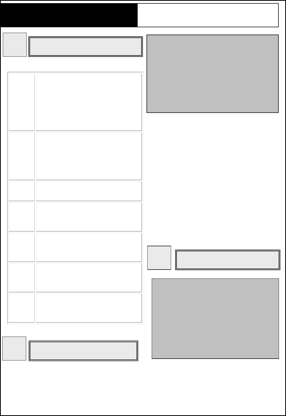
LAN Use standard LAN cables (RJ45
connectors) to connect your PCs to
this port. If required, any port can
be connected to other hub. Any
LAN port will automatically function
as an “Uplink” port when necessary.
WAN Connect the ADSL or Cable Modem
here with RJ45 cable. If your
modem came with a cable, use the
supplied cabled, otherwise, use a
standard LAN cable.
Power DC 12V/1A. Connect the supplied
power adapter here.
WPS Press WPS button to connect with
other WPS complied devices via
secured WLAN connection.
Reset Keep on pressing the Reset button
more than 5 seconds, the unit will
be reset to factory default.
Power
button
Pressing down the button to power
the device up and press it up to
power down.
WiFi
button
Pressing down the button to enable
Wi-Fi connection and press it up to
disable Wi-Fi connection.
NBG6503F/NBG6503P Wireless Router Quick Install Guide
1
Hardware button Overview
Hardware Connection
2
Notes:
Before you start hardware connection, you
are advised to find an appropriate location to
place the device. Usually, the best place is at
the center of your wireless network, with line
of sight to all wireless stations. Also, higher
antenna position usually results in better
p
erformance.
Step1. Connect to your local area network:
connect the Ethernet cable to LAN
port of the device, and the other end
to a PC, hub, switch, router or other
Wireless Access Point.
Step2. Power on the device: connect the
included AC power adapter to the
power port of this wireless router and
other end the wall outlet.
Step3. Check the LEDs: the power LED
should be always on when system is
ready.
Software Configuration
3
Notes:
The operation mode is totally controlled by
hardware slide switch not software. Before
you start to setup the device, you are
advised to change the switch the operation
mode you need. Then the device will
reboot automatically into the mode you
have selected.
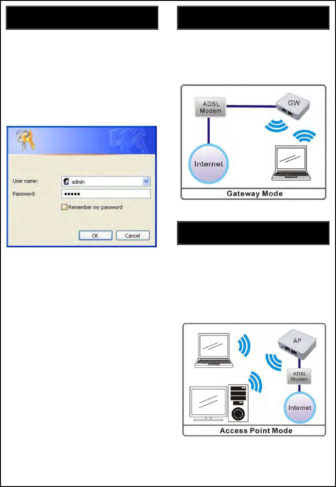
When Gateway mode is selected, the device
will enter gateway mode. And the wireless
connection will be set up from a point-to-point
local LAN into a
p
oint-to-multi
p
oint WAN.
Login
2. Start your computer and make sure the
connection by an Ethernet cable between
your computer and the Wireless Router.
3. Start your WEB Browser.
4. In the Address box, enter the IP address:
192.168.1.1
5. Login User Name admin and Password
1234
Gateway Mode
Access Point Mode
When acting as Access Point (AP), this device
connects all the stations to a wireless network.
All stations can have the Internet access if
only the Access Point has the Internet
connection.
FCC Statement:
Federal Communication Commission Interference Statement
This equipment has been tested and found to comply with the limits for a Class B digital device,
pursuant to Part 15 of the FCC Rules. These limits are designed to provide reasonable protection
against harmful interference in a residential installation. This equipment generates, uses and can
radiate radio frequency energy and, if not installed and used in accordance with the instructions, may
cause harmful interference to radio communications. However, there is no guarantee that interference
will not occur in a particular installation. If this equipment does cause harmful interference to radio or
television reception, which can be determined by turning the equipment off and on, the user is
encouraged to try to correct the interference by one of the following measures:
● Reorient or relocate the receiving antenna.
● Increase the separation between the equipment and receiver.
● Connect the equipment into an outlet on a circuit different from that to which the receiver is
connected.
● Consult the dealer or an experienced radio/TV technician for help.
FCC Caution: Any changes or modifications not expressly approved by the party
responsible for compliance could void the user’s authority to operate this equipment.
This device complies with Part 15 of the FCC Rules. Operation is subject to the following two
conditions: (1) This device may not cause harmful interference, and (2) this device must accept any
interference received, including interference that may cause undesired operation.
For product available in the USA/Canada market, only channel 1~11 can be operated. Selection of
other channels is not possible.
This device and it's antennas(s) must not be co-located or operating in conjunction with any other
antenna or transmitter except in accordance with FCC multi-transmitter product procedures.
This device is going to be operated in 5.15~5.25GHz frequency range, it is restricted in indoor
environment only.
IMPORTANT NOTE:
FCC Radiation Exposure Statement:
This equipment complies with FCC radiation exposure limits set forth for an uncontrolled environment.
This equipment should be installed and operated with minimum distance 20cm between the radiator &
your body.
6
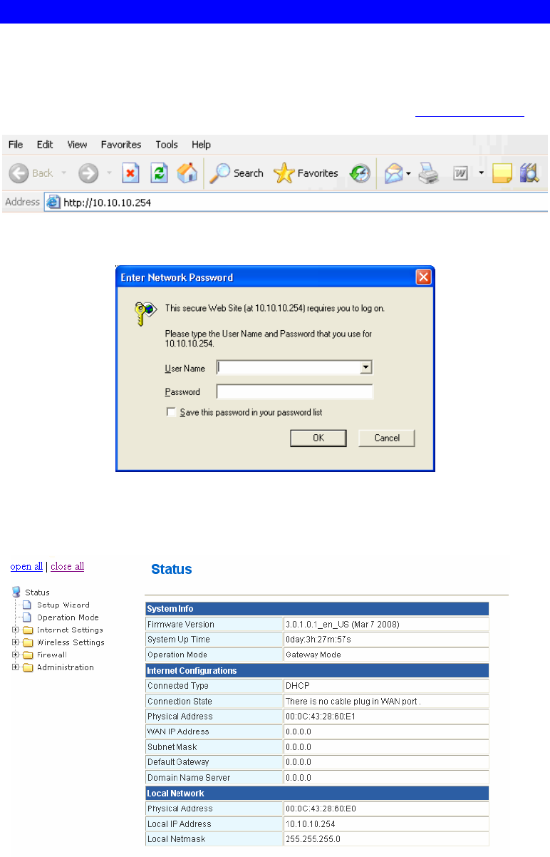
Chapter 3: Router Configuration
Login
1. Start your computer. Connect an Ethernet cable between your computer and the Wireless
Router.
2. Make sure your wired station is set to the same subnet as the Wireless Router, i.e.
10.10.10.254
3. Start your WEB browser. In the Address box, enter the following: http://10.10.10.254
4. Please enter the username “admin” and password “admin” for login.
The configuration menu is divided into four folders: Internet Settings, Wireless Settings,
Firewall, and Administration. Click on the desired setup item to expand the folder in the
main navigation page. The setup pages covered in this utility are described below.

7
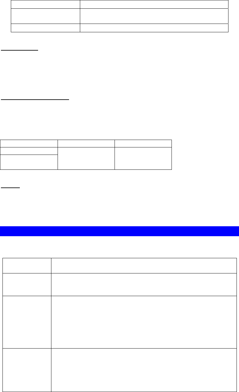
Common Connection Types
Cable Modems
Type Details ISP Data required
Dynamic IP
Address
Your IP Address is
allocated automatically,
when you connect to you
ISP.
Usually, none.
However, some ISP's may
require you to use a particular
Hostname, Domain name, or
MAC (physical) address.
Static (Fixed) IP
Address
Your ISP allocates a
permanent IP Address to
you.
IP Address allocated to you.
Some ISP's may also require
you to use a particular
Hostname, Domain name, or
MAC (physical) address.
DSL Modems
Type Details ISP Data required
Dynamic
IP Address
Your IP Address is allocated
automatically, when you
connect to you ISP.
None.
Static (Fixed)
IP Address
Your ISP allocates a
permanent IP Address to you.
IP Address allocated to you.
PPPoE You connect to the ISP only
when required. The IP address
is usually allocated
automatically.
User name and password.
PPTP Mainly used in Europe.
You connect to the ISP only
when required. The IP address
is usually allocated
automatically, but may be
Static (Fixed).
• PPTP Server IP Address.
• User name and password.
• IP Address allocated to
you, if Static (Fixed).
Other Modems (e.g. Broadband Wireless)
Type Details ISP Data required
Dynamic
IP Address
Your IP Address is allocated
automatically, when you
connect to you ISP.
None.
Static (Fixed)
IP Address
Your ISP allocates a permanent
IP Address to you.
IP Address allocated to you.
8
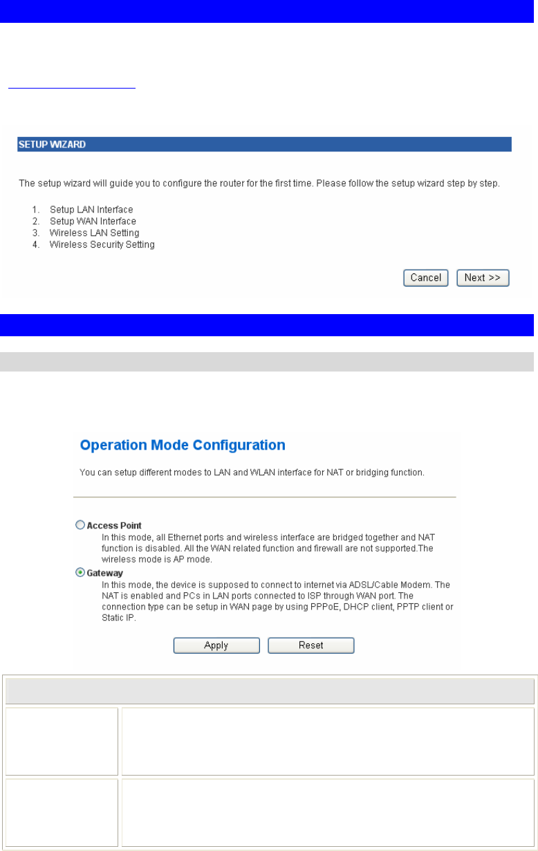
Setup Wizard
The Setup Wizard provides brief and basic configuration of this device, you may enter each
screen to change the default settings. For more detailed settings, you may refer to the
“Configuration via Web” section.
1. View the listed configuration items and click Next to continue.
Configuration via Web
Operation Mode
Select an operation mode then click Apply to enable the mode you preferred or click Reset
button to discard current settings. Default operation mode is Gateway mode.
Operation Mode
Access Point
When acting as an access point, this device connects all the stations
(PC/notebook with wireless network adapter) to a wired network. All
stations can have the Internet access if only the Access Point has the
Internet connection.
Gateway
In this mode, the device is supposed to connect to internet via
ADSL/Cable Modem. The NAT is enabled and PCs in LAN ports share
the same IP to ISP through WAN port. The connection type can be setup
in WAN page by using PPPOE, DHCP client, PPTP client or static IP.
9
Internet Settings
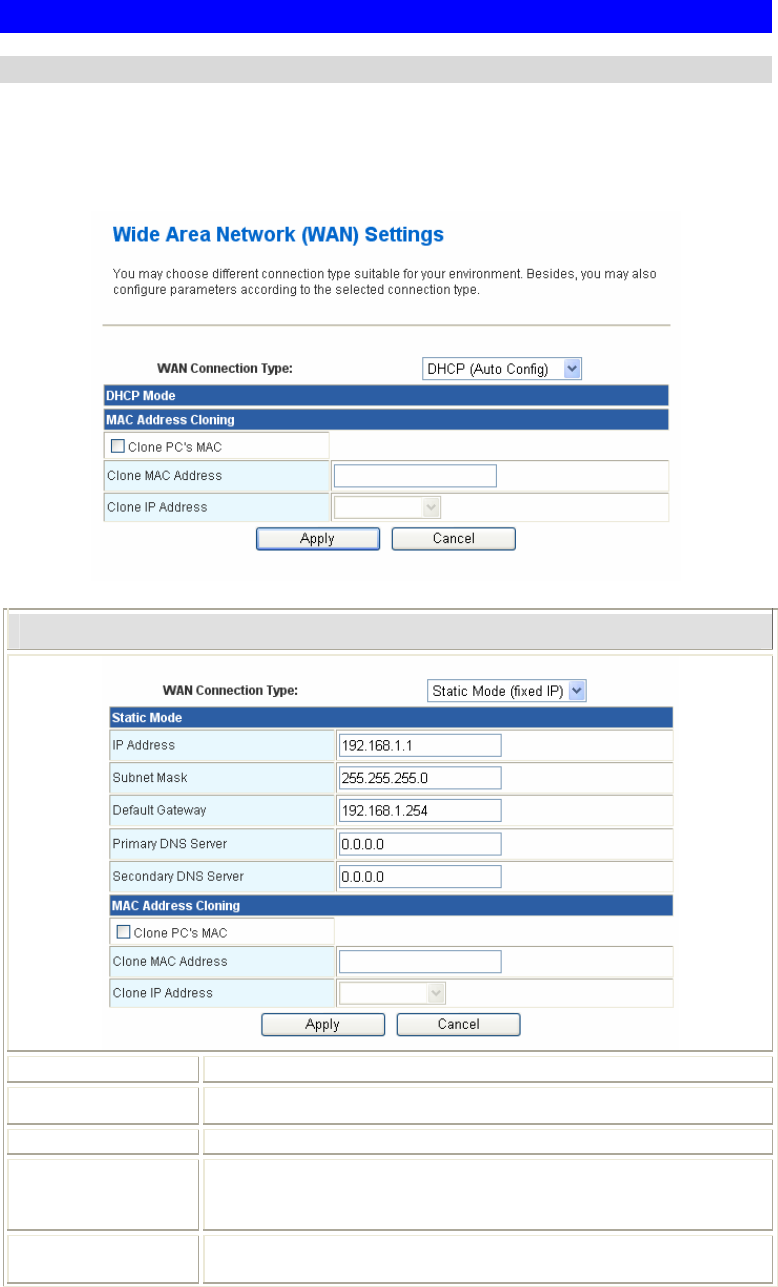
WAN (Wide Area Network) Settings
WAN Connection Type, select the WAN access type (Static Mode (fixed IP), DHCP (Auto
Config), PPPoE (ADSL), L2TP and PPTP) from the pull-down menu. Default setting is DHCP
(Auto Config) Type.
Static Mode
IP Address Enter the WAN IP address provided by your ISP in this column.
Subnet Mask Enter the Subnet Mask in this column.
Default Gateway Enter the default gateway IP provided by your ISP in this column.
Primary and
Secondary DNS
Server
The DNS should be set to the address provided by your ISP.
Clone PC’s MAC
Address Check to enable this function.
10
Clone MAC
Address
Your ISP may require a particular MAC address in order for you to
connect to the Internet. This MAC address is the PC’s MAC
address that your ISP had originally connected your Internet
connection to. Type in this Clone MAC address in this section to
replace the WAN MAC address with the MAC address of that PC.
Clone IP Address Shows the IP address of the device from the pull-down menu.
Apply Click to save and apply the current settings.
Cancel Click to discard the current settings.
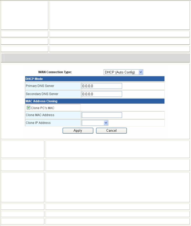
DHCP Mode
Primary and
Secondary DNS
Server
The DNS should be set to the address provided by your ISP.
Clone PC’s MAC
Address Check to enable this function.
Clone MAC
Address
Your ISP may require a particular MAC address in order for you to
connect to the Internet. This MAC address is the PC’s MAC address
that your ISP had originally connected your Internet connection to.
Type in this Clone MAC address in this section to replace the WAN
MAC address with the MAC address of that PC.
Clone IP Address Shows the IP address of the device from the pull-down menu.
Apply Click to save and apply the current settings.
Cancel Click to discard the current settings.
11
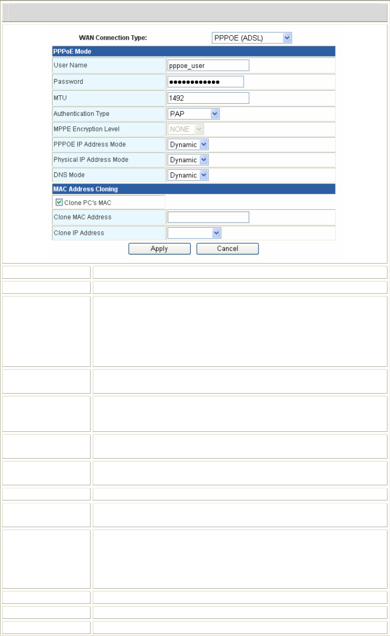
PPPoE Mode
User Name Maximum input is 20 alphanumeric characters (case sensitive).
Password Maximum input is 20 alphanumeric characters (case sensitive).
MTU (Maximum
Transmission
Unit)
Click the pull-down menu to select the most appropriate MTU
(Maximum Transmission Unit, namely the maximum packet size,
the default value is 1492) for your application. Reducing the packet
size can help connecting to certain web sites or speeding up packet
transfer rate. If the incorrect selection is entered, you may not be
able to open certain web sites.
Authentication
Type
Select PAP, CHAP, MSCHAP-v1, MSCHAP-v2 or Auto form the
pull-down menu.
MPPE
Encryption Level
When the authentication type has been set to be MSCHAP-v1,
MSCHAP-v2 or Auto, here can select None, 40 bits, 56bits, 128bits
or Auto form the pull-down menu.
PPPoE IP
Address Mode Select Dynamic or Static for the pull-down menu.
Physical IP
Address Mode Select Dynamic or Static for the pull-down menu.
DNS mode Select from the pull-down menu for Static or Dynamic DNS mode.
Clone PC’s MAC
Address Check to enable this function.
Clone MAC
Address
Your ISP may require a particular MAC address in order for you to
connect to the Internet. This MAC address is the PC’s MAC address
that your ISP had originally connected your Internet connection to.
Type in this Clone MAC address in this section to replace the WAN
MAC address with the MAC address of that PC.
Clone IP Address Shows the IP address of the device from the pull-down menu.
Apply Click to save and apply the current settings.
Cancel Click to discard the current settings.
12
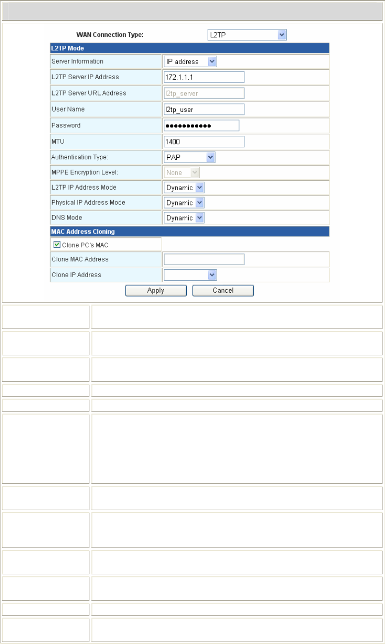
L2TP Mode
Server
Information Select IP address or URL address form the pull-down menu.
L2TP Server IP
Address Enter the L2TP Server IP Address in this column.
L2TP Server
URL Address Enter the L2TP Server URL Address in this column.
User Name Maximum input is 20 alphanumeric characters (case sensitive).
Password Maximum input is 20 alphanumeric characters (case sensitive).
MTU (Maximum
Transmission
Unit)
Click the pull-down menu to select the most appropriate MTU
(Maximum Transmission Unit, namely the maximum packet size,
the default value is 1400) for your application. Reducing the packet
size can help connecting to certain web sites or speeding up packet
transfer rate. If the incorrect selection is entered, you may not be
able to open certain web sites.
Authentication
Type
Select PAP, CHAP, MSCHAP-v1, MSCHAP-v2 or Auto form the
pull-down menu.
MPPE
Encryption Level
When the authentication type has been set to be MSCHAP-v1,
MSCHAP-v2 or Auto, here can select None, 40 bits, 56bits, 128bits
or Auto form the pull-down menu.
L2TP IP
Address Mode Select Dynamic or Static for the pull-down menu.
Physical IP
Address Mode Select Dynamic or Static for the pull-down menu.
DNS mode Select from the pull-down menu for Static or Dynamic DNS mode.
Clone PC’s MAC
Address Check to enable this function.
13
Clone MAC
Address
Your ISP may require a particular MAC address in order for you to
connect to the Internet. This MAC address is the PC’s MAC address
that your ISP had originally connected your Internet connection to.
Type in this Clone MAC address in this section to replace the WAN
MAC address with the MAC address of that PC.
Clone IP Address Shows the IP address of the device from the pull-down menu.
Apply Click to save and apply the current settings.
Cancel Click to discard the current settings.
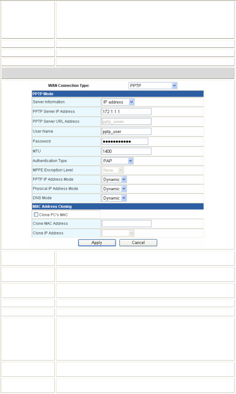
PPTP Mode
Server
Information Select IP address or URL address form the pull-down menu.
PPTP Server IP
Address Enter the PPTP Server IP Address in this column.
PPTP Server
URL Address Enter the PPTP Server URL Address in this column.
User Name Maximum input is 20 alphanumeric characters (case sensitive).
Password Maximum input is 20 alphanumeric characters (case sensitive).
MTU (Maximum
Transmission
Unit)
Click the pull-down menu to select the most appropriate MTU
(Maximum Transmission Unit, namely the maximum packet size,
the default value is 1400) for your application. Reducing the packet
size can help connecting to certain web sites or speeding up packet
transfer rate. If the incorrect selection is entered, you may not be
able to open certain web sites.
Authentication
Type
Select PAP, CHAP, MSCHAP-v1, MSCHAP-v2 or Auto form the
pull-down menu.
MPPE
Encryption Level
When the authentication type has been set to be MSCHAP-v1,
MSCHAP-v2 or Auto, here can select None, 40 bits, 56bits, 128bits
14
or Auto form the pull-down menu.
PPTP IP
Address Mode Select Dynamic or Static for the pull-down menu.
Physical IP
Address Mode Select Dynamic or Static for the pull-down menu.
DNS mode Select from the pull-down menu for Static or Dynamic DNS mode.
Clone PC’s MAC
Address Check to enable this function.
Clone MAC
Address
Your ISP may require a particular MAC address in order for you to
connect to the Internet. This MAC address is the PC’s MAC address
that your ISP had originally connected your Internet connection to.
Type in this Clone MAC address in this section to replace the WAN
MAC address with the MAC address of that PC.
Clone IP Address Shows the IP address of the device from the pull-down menu.
Apply Click to save and apply the current settings.
Cancel Click to discard the current settings.
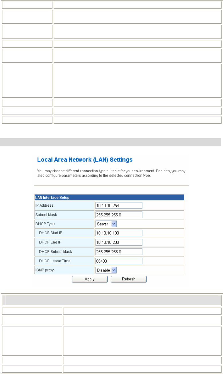
LAN (Local Area Network) Settings
LAN Interface Setup
IP Address Shows the IP address of the router.
Subnet Mask The subnet mask of the router.
DHCP Type Disable: Select to disable this Router to distribute IP addresses.
Server: Select to enable this Router to distribute IP Addresses
(DHCP Server). And the following field will be activated for you
to enter the starting IP Address.
DHCP Start IP The starting address of this local IP network address pool.
DHCP End IP The ending address of this local IP network address pool.
15
DHCP Subnet Mask Shows the DHCP subnet mask.
DHCP Lease Time Default settings are 86400 seconds.
IGMP Proxy Select Disable or Enable from the pull-down menu.
Apply Click to save and apply the current settings.
Refresh Click to get the latest information.
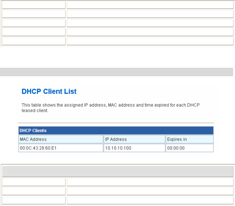
DHCP Clients
DHCP Clients
MAC Address Shows the client MAC address information.
IP Address Shows the client IP address information.
Expires in Shows the expired time of the client.
16
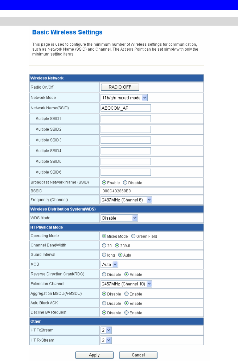
Wireless Settings
Basic
17
Wireless Network
Radio On/Off Click Radio OFF button to turn off the radio function.
Network Mode Select 11 b/g mixed mode, 11b only, 11g only or 11 b/g/n mixed
mode from the pull-down menu. Default is 11 b/g/n mixed mode.
Network Name
(SSID)
A SSID is referred to a network name because essentially it is a
name that identifies a wireless network.
Multiple SSID 1~6 A multiple SSID is referred to a network name because
essentially it is a name that identifies a wireless network.
Broadcast Network
Name(SSID)
Enable: This wireless AP will broadcast its SSID to stations.
Disable: This wireless AP will not broadcast its SSID to stations.
If stations want to connect to this wireless AP, this AP’s SSID
should be known in advance to make a connection.
BSSID Shows the MAC address of the router.
Frequency (Channel) Select 1~11 or Auto Select from the pull-down menu.
Wireless Distribution System(WDS)
WDS Mode Select the mode from the pull-down menu, Disable, Lazy Mode,
Bridge Mode or Repeater Mode.
HT Physical Mode
Operating Mode Select Mixed Mode or Green Field. Default setting is Mixed
Mode.
Channel Band Width Select 20 or 20/40, default setting is 20/40.
Guard Interval Select Long or Auto, default setting is Auto.
MCS Default setting is Auto. Or select form the pull-down menu 0~15,
32 or Auto.
Reverse Direction
Grant(RDG) Select Disable or Enable this function, default setting is Enable.
Extension Channel You can select 2457MHz (Channel 10) or 2417MHz (Channel 2)
form the pull-down menu.
Aggregation MSDU
(A-MSDU) Select Disable or Enable, default setting is Disable.
Auto Block ACK Select Disable or Enable, default setting is Enable.
Decline BA Request Select Disable or Enable, default setting is Disable.
Other
HT Tx Stream Select 1 or 2 form the pull-down menu.
HT Rx Stream Select 1 or 2 form the pull-down menu.
Apply Click to save and apply the current settings.
Cancel Click to discard the current settings.
18
Advanced
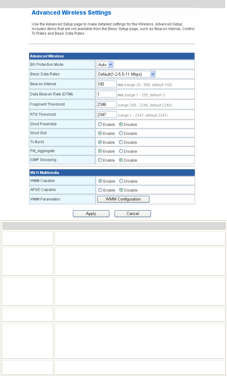
Advanced Wireless
BG Protection
Mode Select Auto, On or Off from the pull-down menu.
Basic Data Rates By default, the unit adaptively selects the highest possible rate for
transmission. Select the basic rates to be used among the following
options: 1-2Mbps, Default (1-2-5.5-11Mbps), or All(1-2-5,5-6-11-12-
24Mbps.)
Beacon Interval Beacon Interval is the amount of time between beacon transmissions.
Before a station enters power save mode, the station needs the beacon
interval to know when to wake up to receive the beacon. Range 20-
999, default is 100.
Data Beacon
Rate (DTIM) Range from 1 to 255, default setting is 1.
Fragment
Threshold
Fragmentation mechanism is used for improving the efficiency when
high traffic flows along in the wireless network. If the 802.11g
MIMO Wireless Router often transmit large files in wireless network,
you can enter new Fragment Threshold value to split the packet. The
value can be set from 256 to 2346. The default value is 2346.
RTS Threshold RTS Threshold is a mechanism implemented to prevent the “Hidden
Node” problem. If the “Hidden Node” problem is an issue, please
19
specify the packet size. The RTS mechanism will be activated if the
data size exceeds the value you set.. The default value is 2347.
Warning: Enabling RTS Threshold will cause redundant network
overhead that could negatively affect the throughput performance
instead of providing a remedy.
This value should remain at its default setting of 2347. Should you encounter
inconsistent data flow, only minor modifications of this value are
recommended.
Short Preamble Select Disable or Enable this function, default setting is Disable. A
preamble is a signal used in wireless environment to synchronize the
transmitting timing including Synchronization and Start frame
delimiter.
Short Slot Select Disable or Enable this function, default setting is Enable.
Tx Burst Select Disable or Enable this function, default setting is Enable.
Pkt_Aggregate Select Disable or Enable this function, default setting is Enable.
IGMP Snooping Select Disable or Enable this function, default setting is Disable.
Wi-Fi Multimedia
WMM Capable Select Disable or Enable this function, default setting is Enable.
APSD Capable Select Disable or Enable this function, default setting is Disable.
WMM
Parameters Click the WMM Configuration button to go further settings.
Apply Click to save and apply the current settings.
Cancel Click to discard the current settings.
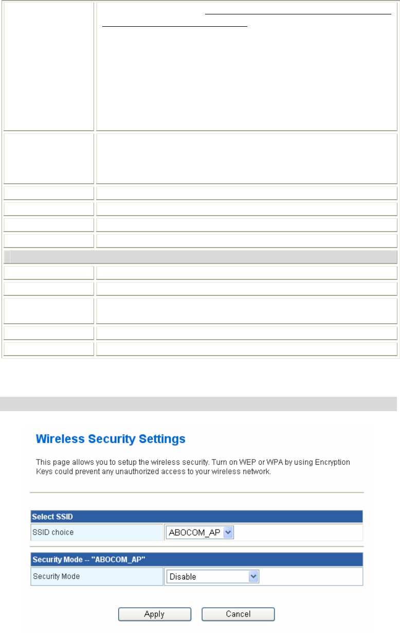
Security

20
Select SSID
SSID choice Select the SSID form the pull-down menu for security settings.
Security Mode There are eleven type of authentication modes including Disable,
Open, Shared, WEP Auto, WPA, WPA-PSK, WPA2, WPA2-
PSK, WPA-PSK/WPA2-PSK, WPA/WPA2 and 802.1X.
• Open: If your wireless router is using "Open” authentication, then the
wireless adapter will need to be set to the same authentication type.
• Shared: Shared key is when both the sender and the recipient share a
secret key.
• WPA, WPA-PSK, WPA2, WPA2-PSK, WPA-PSK/WPA2-
PSK, and WPA1/WPA2: WPA-PSK offers two encryption methods,
TKIP and AES. Select the type of algorithm, TKIP or AES and then enter
a WPA Shared Key of 8~64 characters in the WPA Pre-shared Key field.
Encryption Type: For Open and Shared authentication mode, the
selection of encryption type are None and WEP. For WPA, WPA2,
WPA-PSK and WPA2-PSK authentication mode, the encryption
type supports both TKIP and AES.
WPA Pre-shared Key: This is the shared secret between AP and
STA. For WPA-PSK and WPA2-PSK authentication mode, this field
must be filled with character longer than 8 and less than 64 lengths.
WEP Key: Only valid when using WEP encryption algorithm. The
key must match with the AP’s key. There are several formats to enter
the keys.
• Hexadecimal (128bits): 26 Hex characters (0~9, a~f).
• ASCII (128bits): 13 ASCII characters.
WPA Algorithms Select TKIP, AES or TKIP/AES for the WPA Algorithms.
Enable Pre-
Authentication
The two most important features beyond WPA to become
standardized through 802.11i/WPA2 are: pre-authentication, which
enables secure fast roaming without noticeable signal latency.
RADIUS Server RADIUS is an authentication, authorization and accounting client-
server protocol. The client is a Network Access Server that desires to
authenticate its links. The server is a server that has access to a user
database with authentication information.
IP Address Enter the RADIUS Server’s IP Address provided by your ISP.
Port Enter the RADIUS Server’s port number provided by your ISP. The
default is 1812.
Shared Secret Enter the password that the router shares with the RADIUS Server.
Apply Click to save and apply the current settings.
Cancel Click to discard the current settings.
21
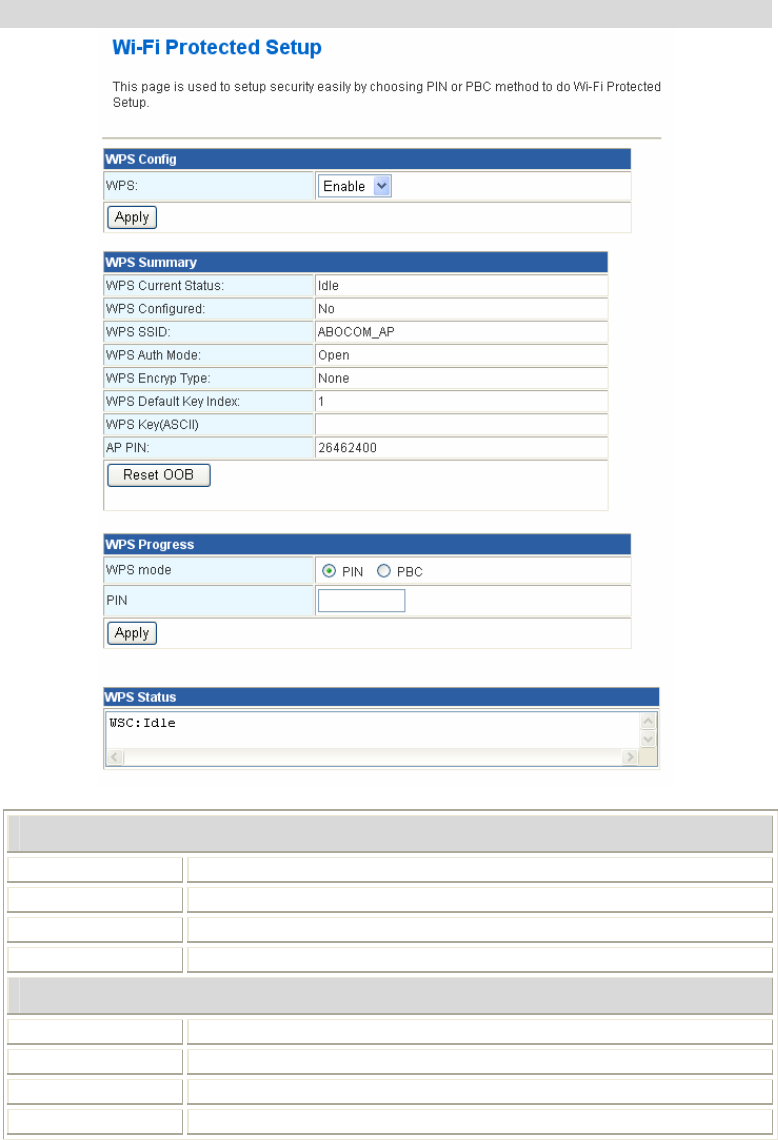
WPS
WPS Configuration
WPS Select Enable or Disable from the pull-down menu.
Apply Click to save and apply the current settings.
WPS Summary Here shows the WPS function status.
Reset OOB Click the button to reset the settings.
WPS Process
WPS mode Select PCB or PIN WPS mode.
PIN Enter the PIN code form the registrar or enrollee.
Apply Click to save and apply the current settings.
WPS Status Here shows the current status of the WPS function.
22
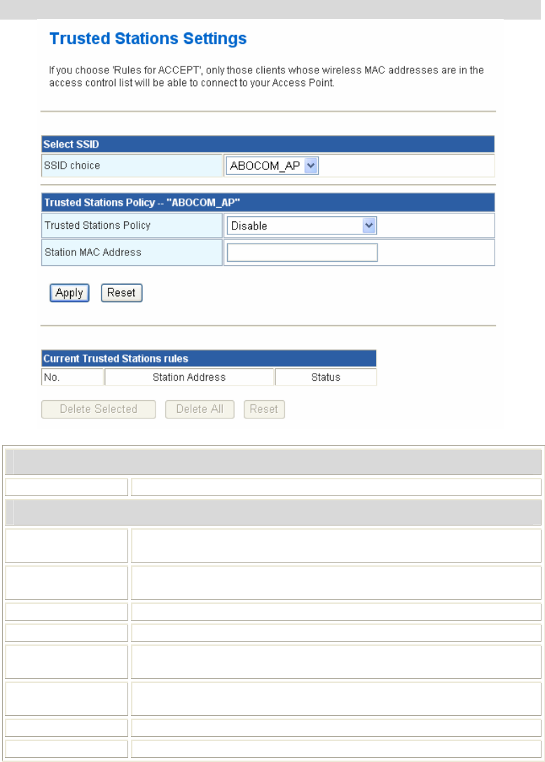
Trusted Stations
Select SSID
SSID choice Select the SSID from the pull-down menu.
Trusted Stations Policy
Trusted Stations
Policy
Select Disable, Enable –Rules for DROP, or Enable –Rules for
ACCEPT form the pull-down menu.
Station MAC
Address Enter the MAC address of the station.
Apply Click to save and apply the current settings.
Reset Press to discard the current settings.
Current Trusted
Stations rules Here shows the information of the trusted stations clients.
Delete Selected Select the unwanted trusted station MAC addresses and then click the
Delete Selected button to eliminate them.
Delete All Click to delete all the trusted station MAC addresses in the table.
Reset Click to clear the current settings.
23
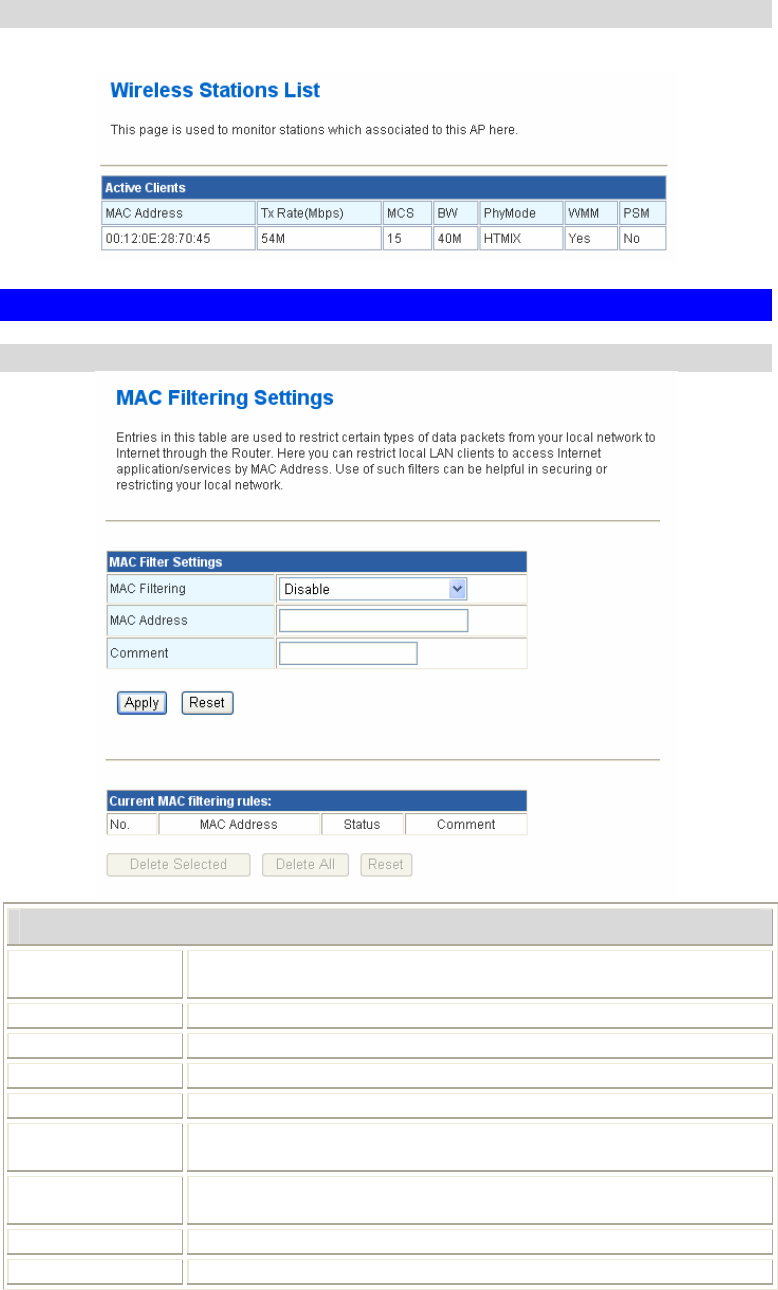
Station List
Here shows the information of stations that connected with the AP.
Firewall
MAC Filtering
MAC Filtering Settings
MAC Filtering Select Disable, enable –Rules for DROP, or enable –Rules for
ACCEPT form the pull-down menu.
MAC Address Enter the client MAC address.
Comment You may key in a description for the MAC address.
Apply Click to save and apply the current settings.
Reset Press to discard the current settings.
Current MAC
filtering rules Here shows the information of the MAC filtering clients.
Delete Selected Select the unwanted MAC addresses and then click the Delete
Selected button to eliminate them.
Delete All Click to delete all the MAC addresses in the table.
Reset Click to clear the current settings.
24
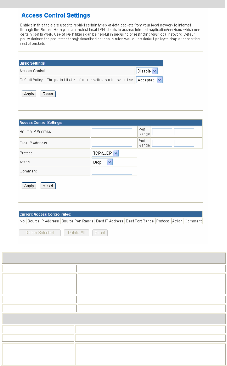
Access Control
Basic Settings
Access Control Select Disable or Enable from the pull-down menu.
Default Policy -- The
packet that don't match
with any rules would be:
Select Accepted or Dropped from the pull-down menu.
Apply Click to save and apply the current settings.
Reset Press to discard the current settings.
Access Control Settings
Source IP Address Enter the client IP address.
Dest IP Address Enter the destined IP address.
Port Range For TCP and UDP services enter the beginning of the range
of port numbers used by the service. If the service uses a
single port number, enter it in both the start and finish fields.
25
Protocol Select the protocol (TCP, UDP or TCP&UDP) used to the
remote system or service.
Action Select Drop or Accept from the pull-down menu.
Comment You may key in a description for the local IP address
Apply Click to save and apply the current settings.
Reset Press to discard the current settings.
Current Access Control
rules Here shows the information of the Access Control clients.
Delete Selected Select the unwanted IP addresses and then click the Delete
Selected button to eliminate them.
Delete All Click to delete all the IP addresses in the table.
Reset Click to clear the current settings.
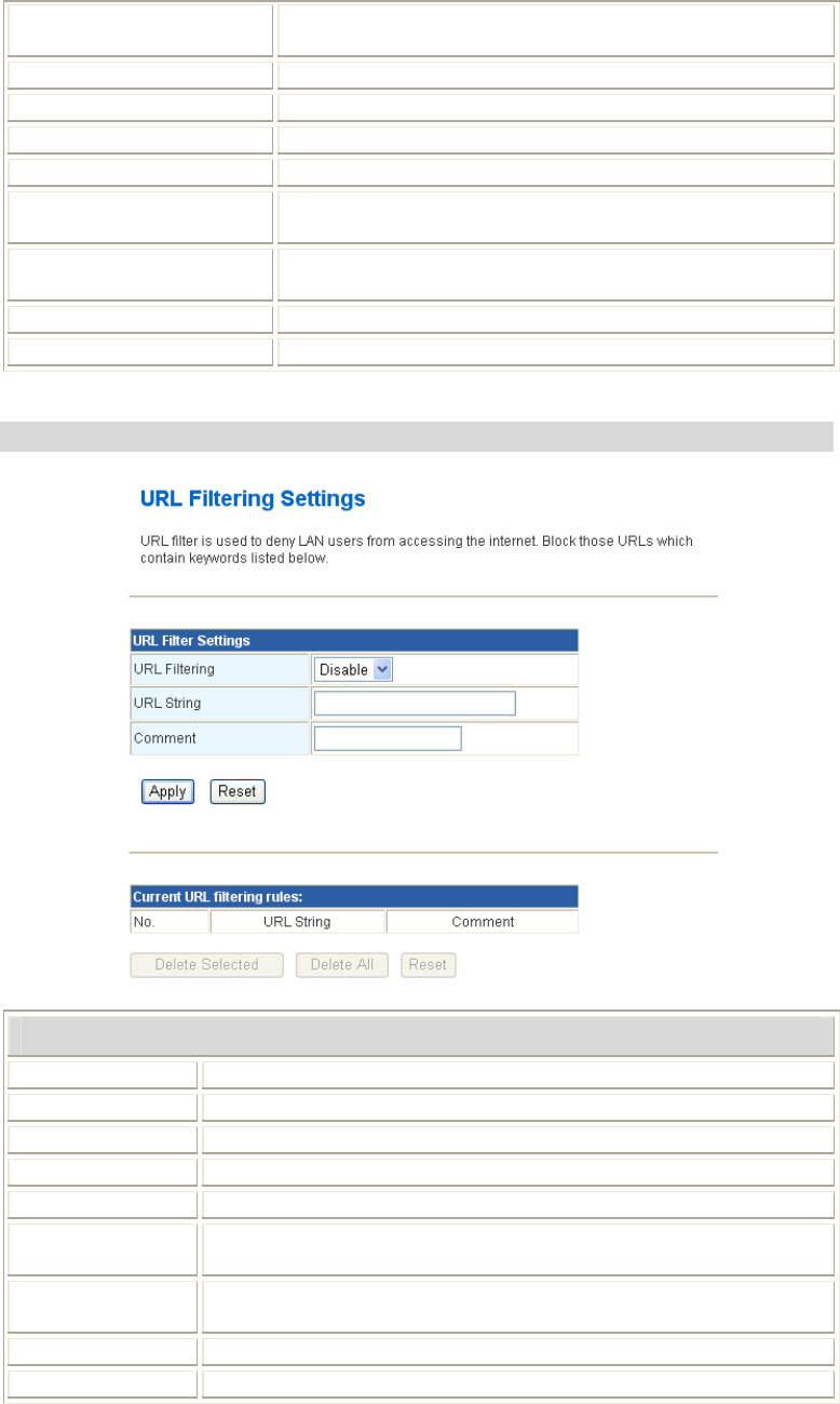
URL Filtering
URL Filter Settings
URL Filtering Select Disable or Enable from the pull-down menu.
URL String You can block websites with specific URL addresses.
Comment You may key in a description for the URL address.
Apply Click to save and apply the current settings.
Reset Press to discard the current settings.
Current URL
filtering rules Shows the current URL address status.
Delete Selected Select the unwanted URL addresses and then click the Delete
Selected button to eliminate them.
Delete All Click to delete all the URL addresses in the table.
Reset Click to clear the current settings.
26
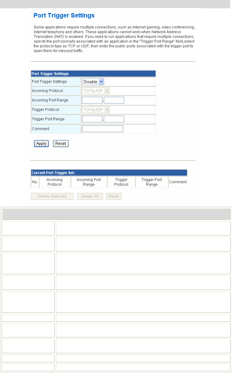
Port Trigger
Port Trigger Settings
Port Trigger
Settings Select Disable or Enable from the pull-down menu.
Incoming
Protocol
Select the protocol (TCP, UDP or TCP&UDP) used to the remote
system or service.
Incoming Port
Range
For TCP and UDP Services, enter the beginning of the range of port
numbers used by the service. If the service uses a single port number,
enter it in both the start and finish fields.
Trigger Protocol Select the protocol (TCP, UDP or TCP&UDP) used to the remote
system or service.
Trigger Port
Range
For TCP and UDP Services, enter the beginning of the range of port
numbers used by the service. If the service uses a single port number,
enter it in both the start and finish fields.
Comment You may key in a description for the port trigger.
Current Port
Trigger list Shows the current Port Trigger status.
Delete Selected Select the unwanted URL addresses and then click the Delete
Selected button to eliminate them.
Delete All Click to delete all the URL addresses in the table.
Reset Click to clear the current settings.
27
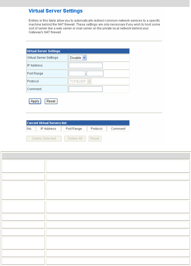
Virtual Server
Virtual Server Settings
Virtual Server
Settings Select Enable or Disable from the pull-down menu.
IP Address Enter the local server’s IP address.
Port Range For TCP and UDP services enter the beginning of the range of port
numbers used by the service. If the service uses a single port number,
enter it in both the start and finish fields.
Protocol Select the protocol (TCP, UDP or TCP&UDP) used to the remote
system or service.
Comment You may key in a description for the IP address.
Apply Click to save and apply the current settings.
Reset Press to discard the current settings.
Delete Selected Select the unwanted IP addresses and then click the Delete Selected
button to eliminate them.
Delete All Click to delete all the IP addresses in the table.
Reset Click to clear the current settings.
28
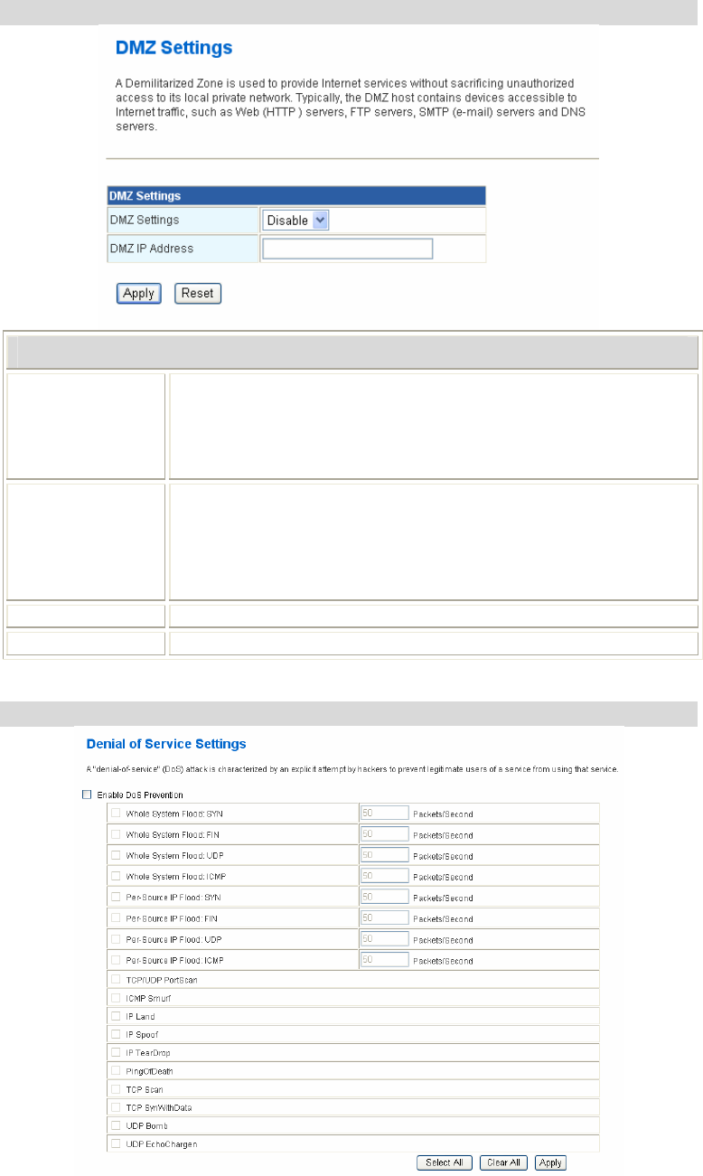
DMZ
DMZ Settings
DMZ Settings If the DMZ Host Function is enabled, it means that you set up DMZ
host at a particular computer to be exposed to the Internet so that
some applications/software, especially Internet / online game can
have two-way connections. Select Enable or Disable from the pull-
down menu.
DMZ IP Address Enter the IP address of a particular host in your LAN that will receive
all the packets originally going to the WAN port/ Public IP address
above.
Note: You need to give your LAN PC clients a fixed/ static IP
address for DMZ to work properly.
Apply Click to save and apply the current settings.
Reset Press to discard current settings.
Denial of Service
29
Denial of Service Settings
Enable DoS
Prevention
DoS (Denial of Service) attacks can flood your Internet connection
with invalid packets and connection requests, using so much
bandwidth and so many resources that Internet access becomes
unavailable. The Wireless Router incorporates protection against DoS
attacks. This screen allows you to configure DoS protection.
Check the box to enable the DoS settings.
Select All After you enabled the DoS prevention, you can click to select all DoS
preventions.
Clear All After you enabled the DoS prevention, you can click to uncheck all
DoS preventions.
Apply Click to enable selected DoS preventions.
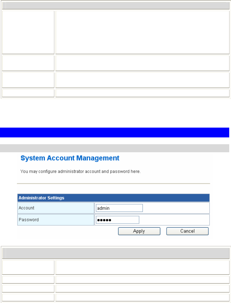
Administration
User/ Password
Administrator Settings
Account Enter the user name for managing this device. Maximum Input is 16
alphanumeric characters.
Password Enter the passwords for managing this device.
Apply Click to save and apply the current settings.
Cancel Click to discard the current settings.

30
Time Zone Setting
Time Zone Management
Current Time Here shows the current time information.
Enable NTP Client Check the box to enable below time zone settings.
Time Zone Select Select the preferred time zone from the pull-down menu.
NTP Servers
Auto Selection: Select Auto Selection to choose the server
automatically.
Manual IP: Enter an IP address of a specific server.
Daylight Saving Check the box to enable this function, select start and end date
from the pull-down menu.
Save Click to save the current settings.
Refresh Click to renew the current settings.
Smart Update Click to update the current time information.
31
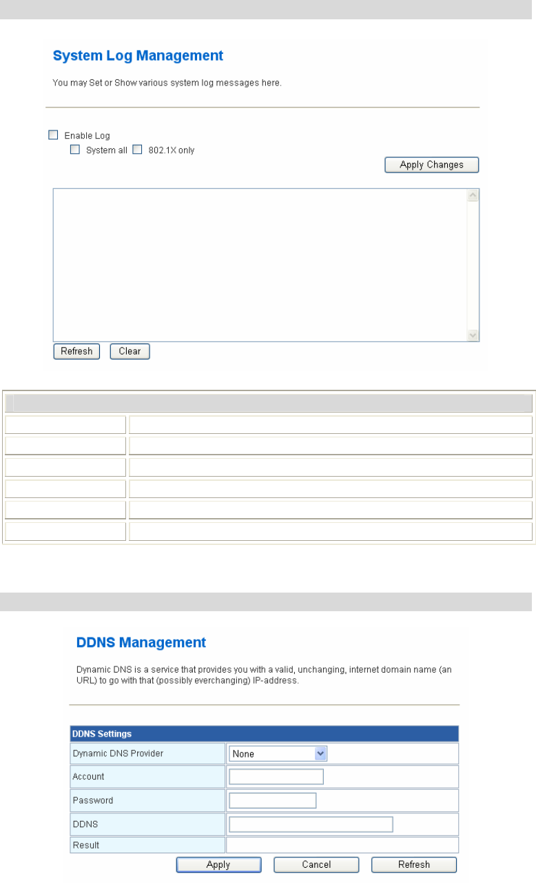
System Log
System Log Management
Enable Log Check the box to enable this function.
System all Check to show all system related log files.
802.1X only Check to show 802.1X log file only.
Apply Changes Click this button to save the settings.
Refresh Click to renew the current log message.
Clear Click to remove current log message.
DDNS
32
DDNS Settings
Dynamic DNS
Provider • Select the desired DDNS Service Provider None, Dyndns.org,
www.zoneedit.com, or www.no-ip.com from the pull-down list.
• Details of your DDNS account (Name, password, Domain name)
must then be entered and saved on this screen.
• This device will then automatically ensure that your current IP
Address is recorded by the DDNS Service Provider.
• From the Internet, users will now be able to connect to your
Virtual Servers (or DMZ PC) using your Domain name.
Account Enter the user name for managing this device.
Password Enter the password for managing this device.
DDNS Apply for a Domain Name, and ensure it is allocated to you.
Result The result of the update DNS result will show here.
Apply Click to save and apply the current settings.
Cancel Click to discard the current settings.
Refresh Click to refresh the settings.
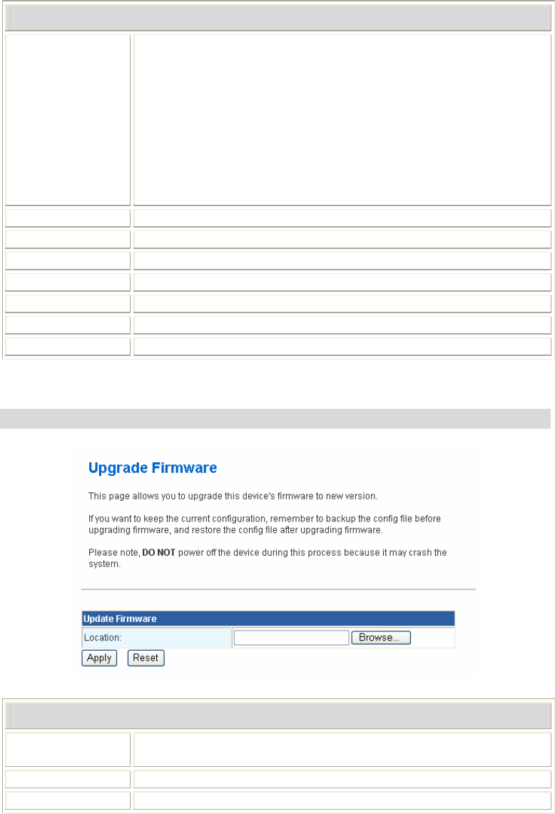
Upload Firmware
Update Firmware
Location Click the Browse button, find and open the firmware file (the
browser will display to correct file path).
Apply Click the Apply button to perform.
Reset Click Reset to restore to default values.
33
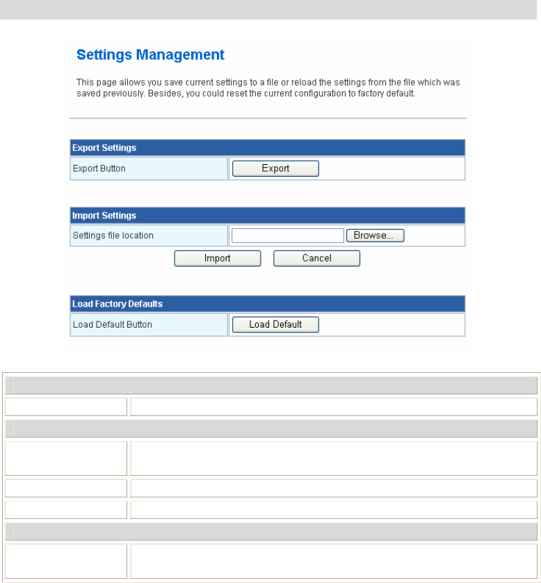
Settings Management
Export Settings
Export Button Click the Export button to export the current device settings.
Import Settings
Settings file
location
Click the Browse button, find and open the file that has been saved
before. (The browser will display to correct file path).
Import Click the Import button to import the device settings.
Cancel Click to discard the current settings.
Load Factory Defaults
Load Default
Button
Click to Load Default button to set the device back to factory default
settings.
34
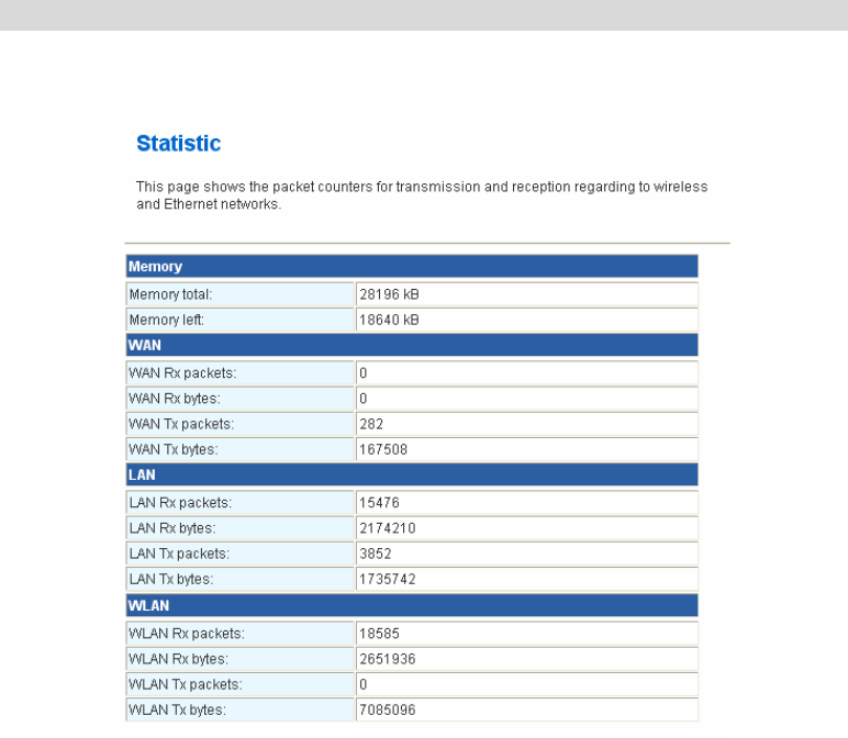
Statistics
This screen displays the transmission and reception statistics on your current networks.

35
Chapter 4: PC Configuration
Overview
For each PC, the following may need to be configured:
• TCP/IP network settings
• Internet Access configuration
• Wireless configuration
Windows Clients
• This section describes how to configure Windows clients for Internet access via the
Wireless Router.
• The first step is to check the PC's TCP/IP settings.
• The Wireless Router uses the TCP/IP network protocol for all functions, so it is essential
that the TCP/IP protocol be installed and configured on each PC.
TCP/IP Settings - Overview
If using default Wireless Router settings, and default Windows TCP/IP
settings, no changes need to be made.
• By default, the Wireless Router will act as a DHCP Server, automatically providing a
suitable IP Address (and related information) to each PC when the PC boots.
• For all non-Server versions of Windows, the default TCP/IP setting is to act as a DHCP
client.
If using a Fixed (specified) IP address, the following changes are
required:
• The Gateway must be set to the IP address of the Wireless Router.
• The DNS should be set to the address provided by your ISP.
36
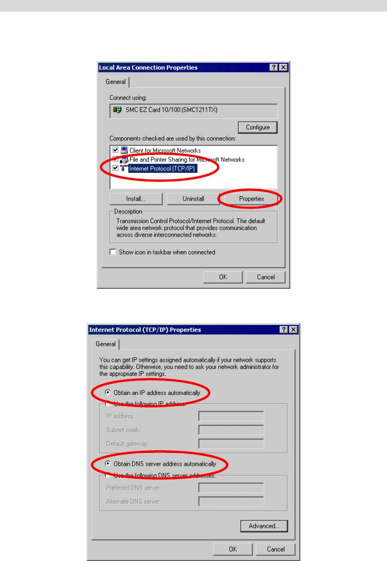
Checking TCP/IP Settings - Windows 2000
1. Select Control Panel - Network and Dial-up Connection.
2. Right - click the Local Area Connection icon and select Properties. You should see a
screen like the following:
3. Select the TCP/IP protocol for your network card.
4. Click on the Properties button. You should then see a screen like the following.
5. Ensure your TCP/IP settings are correct, as described below.
37
Using DHCP
• To use DHCP, select the radio button Obtain an IP Address automatically. This is the
default Windows setting. Using this is recommended. By default, the Wireless Router
will act as a DHCP Server.
• Restart your PC to ensure it obtains an IP Address from the Wireless Router.
Using a fixed IP Address ("Use the following IP Address")
If your PC is already configured, check with your network administrator before making the
following changes.
• Enter the Wireless Router's IP address in the Default gateway field and click OK. (Your
LAN administrator can advise you of the IP Address they assigned to the Wireless Router.)
• If the DNS Server fields are empty, select Use the following DNS server addresses, and
enters the DNS address or addresses provided by your ISP, then click OK.
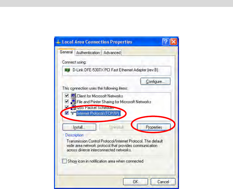
Checking TCP/IP Settings - Windows XP
1. Select Control Panel - Network Connection.
2. Right click the Local Area Connection and choose Properties. You should see a screen
like the following:
3. Select the TCP/IP protocol for your network card.
4. Click on the Properties button. You should then see a screen like the following.
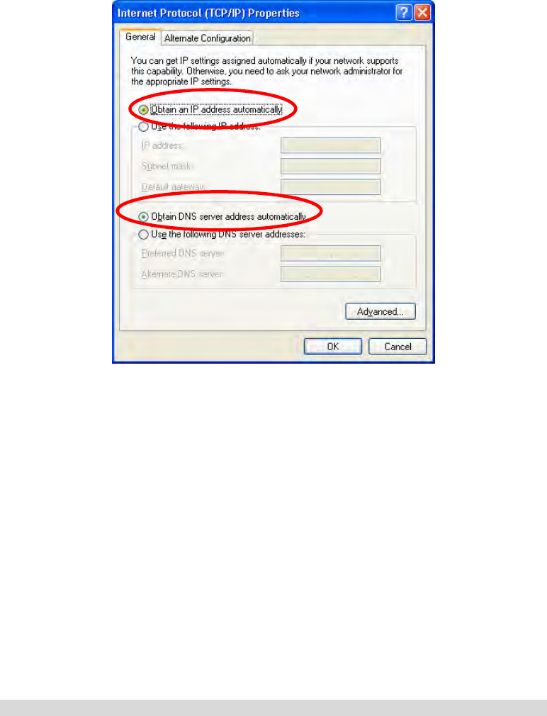
38
5. Ensure your TCP/IP settings are correct.
Using DHCP
• To use DHCP, select Obtain an IP Address automatically. This is the default Windows
setting. Using this is recommended. By default, the Wireless Router will act as a DHCP
Server.
• Restart your PC to ensure it obtains an IP Address from the Wireless Router.
Using a fixed IP Address ("Use the following IP Address")
If your PC is already configured, check with your network administrator before making the
following changes.
• In the Default gateway field, enter the Wireless Router's IP address and click OK. Your
LAN administrator can advise you of the IP Address they assigned to the Wireless Router.
• If the DNS Server fields are empty, select Use the following DNS server addresses, and
enters the DNS address or addresses provided by your ISP, then click OK.
Internet Access
To configure your PCs to use the Wireless Router for Internet access:
• Ensure that the DSL modem, Cable modem, or other permanent connection is functional.
• Use the following procedure to configure your Browser to access the Internet via the LAN,
rather than by a Dial-up connection.

39
For Windows 2000
1. Select Start Menu - Settings - Control Panel - Internet Options.
2. Select the Connection tab, and click the Setup button.
3. Select "I want to set up my Internet connection manually, or I want to connect through a
local area network (LAN)" and click Next.
4. Select "I connect through a local area network (LAN)" and click Next.
5. Ensure all of the boxes on the following Local area network Internet Configuration
screen are unchecked.
6. Check the "No" option when prompted "Do you want to set up an Internet mail account
now?"
7. Click Finish to close the Internet Connection Wizard. Setup is now completed.
For Windows XP
1. Select Start Menu - Control Panel - Network and Internet Connections.
2. Select Set up or change your Internet Connection.
3. Select the Connection tab, and click the Setup button.
4. Cancel the pop-up "Location Information" screen.
5. Click Next on the "New Connection Wizard" screen.
6. Select "Connect to the Internet" and click Next.
7. Select "Set up my connection manually" and click Next.
8. Check "Connect using a broadband connection that is always on" and click Next.
9. Click Finish to close the New Connection Wizard. Setup is now completed.
Accessing AOL
To access AOL (America On Line) through the Wireless Router, the AOL for Windows
software must be configured to use TCP/IP network access, rather than a dial-up connection.
The configuration process is as follows:
1. Start the AOL for Windows communication software. Ensure that it is Version 2.5, 3.0 or
later. This procedure will not work with earlier versions.
2. Click the Setup button.
3. Select Create Location, and change the location name from "New Locality" to "Wireless
Router."
4. Click Edit Location. Select TCP/IP for the Network field. (Leave the Phone Number
blank.)
5. Click Save, then OK. Configuration is now complete.
6. Before clicking "Sign On", always ensure that you are using the "Wireless Router"
location.

40
Macintosh Clients
From your Macintosh, you can access the Internet via the Wireless Router. The procedure is as
follows.
1. Open the TCP/IP Control Panel.
2. Select Ethernet from the Connect via pop-up menu.
3. Select Using DHCP Server from the Configure pop-up menu. The DHCP Client ID field
can be left blank.
4. Close the TCP/IP panel, saving your settings.
Note:
If using manually assigned IP addresses instead of DHCP, the required changes are:
• Set the Router Address field to the Wireless Router's IP Address.
• Ensure your DNS settings are correct.
Linux Clients
To access the Internet via the Wireless Router, it is only necessary to set the Wireless Router as
the "Gateway".
Ensure you are logged in as "root" before attempting any changes.
Fixed IP Address
By default, most Unix installations use a fixed IP Address. If you wish to continue using a
fixed IP Address, make the following changes to your configuration.
• Set your "Default Gateway" to the IP Address of the Wireless Router.
• Ensure your DNS (Name server) settings are correct.
To act as a DHCP Client (Recommended)
The procedure below may vary according to your version of Linux and X -windows shell.
1. Start your X Windows client.
2. Select Control Panel - Network
3. Select the "Interface" entry for your Network card. Normally, this will be called "eth0".
4. Click the Edit button, set the "protocol" to "DHCP", and save this data.
5. To apply your changes:
• Use the "Deactivate" and "Activate" buttons, if available.
• OR, restart your system.
Other Unix Systems
To access the Internet via the Wireless Router:
• Ensure the "Gateway" field for your network card is set to the IP Address of the Wireless
Router.
• Ensure your DNS (Name Server) settings are correct.

41
Wireless Station Configuration
• This section applies to all Wireless stations wishing to use the Wireless Router's Access
Point, regardless of the operating system that is used on the client.
• To use the Wireless Station with Wireless Router, each Wireless Station must have
compatible settings, as follows:
Mode The mode must be set to Infrastructure.
SSID (ESSID)
This must match the value used on the Wireless Router. The default
value is Untitled.
Note! The SSID is case sensitive.
WEP
By default, the security setting on the Wireless Router is Disabled.
• If security setting remains disabled on the Wireless Router, all
stations must have it disabled.
• If security setting is enabled on the Wireless Router, each station
must use the same settings as the Wireless Router.
WPA
WPA2 (AES)
WPA2 Mixed
WPA (TKIP/AES)/ WPA2 (AES)/ WPA2 Mixed: If one of these
securities is enabled on the Wireless Router, each station must use the
same settings as the Wireless Router. If there is no security is enabled on
the Wireless Router, the security of each station should be disabled as
well.
Note: By default, the Wireless Router will allow both 802.11b and 802.11g connections.

Appendix A:
Troubleshooting
Overview
This chapter covers some common problems that may be encountered while using the Wireless
Router and some possible solutions to them. If you follow the suggested steps and the Wireless
Router still does not function properly, contact your dealer for further advice.
General Problems
Problem 1: Can't connect to the Wireless Router to configure it.
Solution 1: Check the following:
• The Wireless Router is properly installed, LAN connections are OK,
and it is powered ON.
• Ensure that your PC and the Wireless Router are on the same network
segment. (If you don't have a router, this must be the case.)
• If your PC is set to "Obtain an IP Address automatically" (DHCP
client), restart it.
• If your PC uses a Fixed (Static) IP address, ensure that it is using an IP
Address within the range 10.10.10.1 to 10.10.10.253 and thus
compatible with the Wireless Router's default IP Address of
10.10.10.254.
Also, the Network Mask should be set to 255.255.255.0 to match the
Wireless Router.
In Windows, you can check these settings by using Control Panel-
Network to check the Properties for the TCP/IP protocol.
Internet Access
Problem 1: When I enter a URL or IP address I get a time out error.
Solution 1: A number of things could be causing this. Try the following troubleshooting
steps.
• Check if other PCs work. If they do, ensure that your PCs IP settings are
correct. If using a Fixed (Static) IP Address, check the Network Mask,
Default gateway and DNS as well as the IP Address.
• If the PCs are configured correctly, but still not working, check the
Wireless Router. Ensure that it is connected and ON. Connect to it and
check its settings. (If you can't connect to it, check the LAN and power
connections.)
• If the Wireless Router is configured correctly, check your Internet
connection (DSL/Cable modem etc) to see that it is working correctly.
Problem 2: Some applications do not run properly when using the Wireless Router.
Solution 2: The Wireless Router processes the data passing through it, so it is not
transparent.
Use the Special Applications feature to allow the use of Internet
applications, which do not function correctly. If this does solve the problem
you can use the DMZ function. This should work with almost every
application, but:
• It is a security risk, since the firewall is disabled.
• Only one (1) PC can use this feature.
A

43
Wireless Access
Problem 1: My PC can't locate the Wireless Router.
Solution 1: Check the following:
• Your PC is set to Infrastructure Mode. (Access Points are always in
Infrastructure Mode.)
• The SSID on your PC and the Wireless Router are the same.
Remember that the SSID is case-sensitive. So, for example
"Workgroup" does NOT match "workgroup".
• Both your PC and the Wireless Router must have the same setting for
security. The default setting for the Wireless Router is disabled, so your
wireless station should also have security setting disabled.
• If security setting is enabled on the Wireless Router, your PC must have
it enabled, and the password or key must match.
• If the Wireless Router's Wireless screen is set to Allow LAN access to
selected Wireless Stations only, then each of your Wireless stations
must have been selected, or access will be blocked.
• To see if radio interference is causing a problem, see if connection is
possible when close to the Wireless Router. Remember that the
connection range can be as little as 100 feet in poor environments.
Problem 2: Wireless connection speed is very slow.
Solution 2: The wireless system will connect at the highest possible speed, depending
on the distance and the environment. To obtain the highest possible
connection speed, you can experiment with the following:
• Wireless Router location.
Try adjusting the location and orientation of the Wireless Router.
• Wireless Channel.
If interference is the problem, changing to another channel may show a
marked improvement.
• Radio Interference.
Other devices may be causing interference. You can experiment by
switching other devices Off, and see if this helps. Any "noisy" devices
should be shielded or relocated.
• RF Shielding.
Your environment may tend to block transmission between the wireless
stations. This will mean high access speed is only possible when close
to the Wireless Router.

Appendix B:
About Wireless LANs
BSS
BSS
A group of Wireless Stations and a single Access Point, all using the same ID (SSID), form a
Basic Service Set (BSS).
Using the same SSID is essential. Devices with different SSIDs are unable to communicate
with each other.
Channels
The Wireless Channel sets the radio frequency used for communication.
• Access Points use a fixed Channel. You can select the Channel used. This allows you to
choose a Channel which provides the least interference and best performance. In the USA
and Canada, 11 channel are available. If using multiple Access Points, it is better if
adjacent Access Points use different Channels to reduce interference.
• In "Infrastructure" mode, Wireless Stations normally scan all Channels, looking for an
Access Point. If more than one Access Point can be used, the one with the strongest signal
is used. (This can only happen within an ESS.)
Security
Authentication methods include Disable, Open, Shared, WEP Auto, WPA, WPA-PSK,
WPA2, WPA2-PSK, WPA-PSK/WPA2-PSK, WPA1/WPA2 and 802.1X. Once you choose
your authentication, you then need to select the Data Encryption methods which may includes
WEP Key, Pass Phrase and Radius Server settings.
Encryption
Enabling WEP can protect your data from eavesdroppers. There are two levels of WEP
Encryption: 64 bits and 128 bits. 64 bits WEP encryption requires enter 10 Hex characters as a
“secret key”, whereas 128 bits WEP requires users to enter 26 Hex characters as “secret key”.
PASS PHRASE is applicable only when you select to use WPA-PSK authentication. You will
need to enter an 8~63 characters password to kick off the encryption process, which will
generate four WEP keys automatically.
RADIUS setup is used to set up additional parameters for authorizing wireless clients through
RADIUS server. The RADIUS setup is required when you select to use Open System with
802.1x or WPA/WPA2 authentication.
Open, Shared, WEP auto
With Shared Key or Open System, the Wireless Router can automatically change its
authentication method to Shared Key or Open System depending on its client’s setting.
WEP (Wired Equivalent Privacy) is a standard for encrypting data before it is transmitted.
This is desirable because it is impossible to prevent snoopers from receiving any data that is
transmitted by your Wireless Stations. But if the data is encrypted, then it is meaningless unless
the receiver can decrypt it.
If WEP is used, the Wireless Stations and the Access Point must have the same settings
for each of the following:
B
45
WEP Off, 64 Bit, 128 Bit.
Key For 64 Bit encryption, the Key value must match.
For 128 Bit encryption, the Key value must match.
WEP Authentication Open System or Shared Key.
WPA/WPA2
WPA/WPA2 (Wi-Fi Protected Access) is more secure than WEP. It uses a “Shared Key”
which allows the encryption keys to be regenerated at a specified interval. There are four
encryption options: TKIP, AES, TKIP-AES and additional setup for RADIUS is required in
this method.
WPA-PSK/WPA2-PSK
WPA/WPA2 (Wi-Fi Protected Access using Pre-Shared Key) is recommended for users who
are not using a RADIUS server in a home environment and all their clients support
WPA/WPA2. This method provides a better security.
Encryption WEP Key 1~4 Passphrase
TKIP
AES NOT REQUIRED 8-63 characters
802.1x
With 802.1x authentication, a wireless PC can join any network and receive any messages that
are not encrypted, however, additional setup for RADIUS to issue the WEP key dynamically
will be required.
Wireless LAN Configuration
To allow Wireless Stations to use the Access Point, the Wireless Stations and the Access Point
must use the same settings, as follows:
Mode On client Wireless Stations, the mode must be set to "Infrastructure."
(The Access Point is always in "Infrastructure" mode.)
SSID (ESSID)
Wireless Stations should use the same SSID (ESSID) as the Access
Point they wish to connect to, but the SSID can not set to be null
(blank).
WEP
The Wireless Stations and the Access Point must use the same settings
for WEP (Off, 64 Bit, 128 Bit).
WEP Key: If WEP is enabled, the Key must be the same on the
Wireless Stations and the Access Point.
WEP Authentication: If WEP is enabled, all Wireless Stations must
use the same setting as the Access Point (either "Open System" or
"Shared Key").
WPA
WPA2 (AES)
WPA2 Mixed
WPA (TKIP/AES)/ WPA2 (AES)/ WPA2 Mixed: If one of these
securities is enabled on the Wireless Router, each station must use the
same settings as the Wireless Router. If there is no security is enabled
on the Wireless Router, the security of each station should be disabled
as well.

46
Regulatory Approvals
CE Standards
This product complies with the 99/5/EEC directives, including the following safety and EMC
standards:
• EN300328-2
• EN301489-1/-17
• EN60950
CE Marking Warning
This is a Class B product. In a domestic environment this product may cause radio interference
in which case the user may be required to take adequate measures.