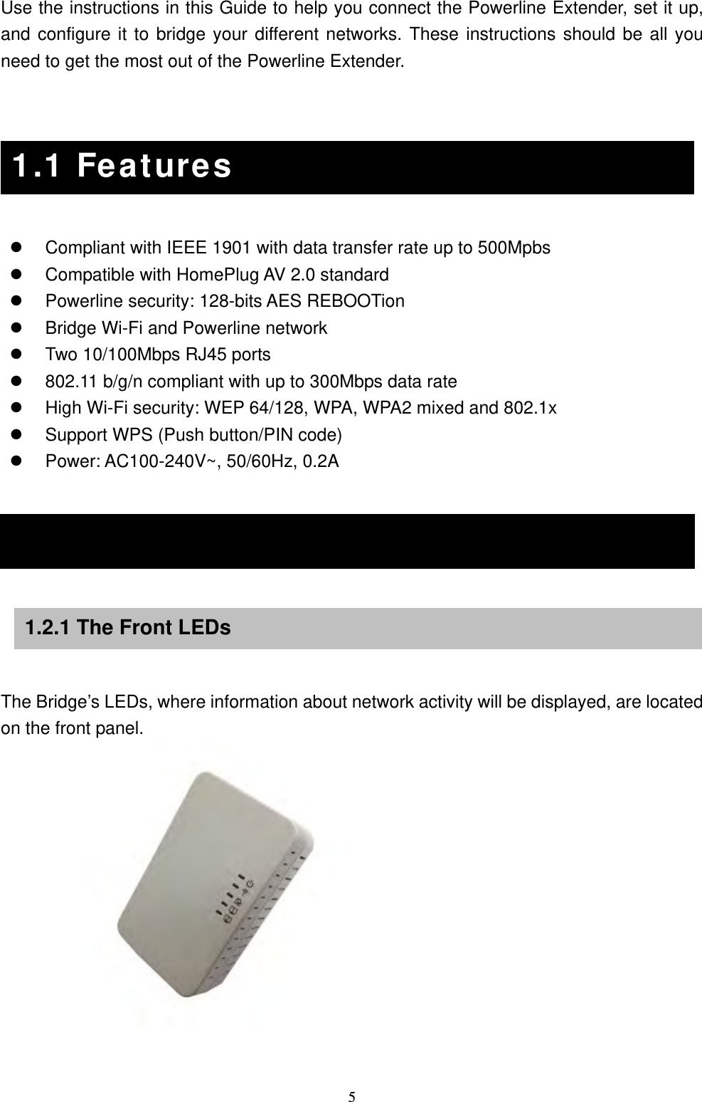
Abocom Systems PLW5Z 500Mbps Powerline Wireless-N Extender User Manual PLW5Z Generic ok

Abocom Systems Inc 500Mbps Powerline Wireless-N Extender PLW5Z Generic ok

User Manual

 1  500Mbps Powerline Wireless-N Extender  PLW5Z  User Manual
 2How to Use this User Guide The user guide to the 500Mbps Powerline Wireless-N Extender has been designed to make understanding networking with the Powerline Wireless-N Extender easier than ever. Look for the following items when reading this User Guide:   This checkmark means there is a note of interest and is something you should pay special attention to while using the Powerline Wireless-N Extender.    This exclamation point means there is a caution or warning and is something that could damage your property on the Powerline Wireless-N Extender.
 3 Chapter 1: Introduction........................................................................................................ 4 1.1 Features............................................................................................................................... 5 1.2 Physical Details................................................................................................................... 5 1.3 Setup Security on Powerline............................................................................................... 7 1.4 Setup Multiple Powerline Networks................................................................................... 8 1.5 The WPS Button ................................................................................................................. 9 1.6 Reset the Powerline........................................................................................................... 10 1.7 The RESET/REBOOT Button .......................................................................................... 11 1.8 Low Power Mode.............................................................................................................. 13 1.9 How to pair your powerlines............................................................................................. 14 1.10 Set up Multiple powerline Network................................................................................ 15 Chapter 2: WEB Configuration........................................................................................ 16 2.1 Login................................................................................................................................. 16 2.2 Network Settings............................................................................................................... 18 2.3 Wireless Settings............................................................................................................... 19 2.4 Power Line Communication ............................................................................................. 25 2.5 Administration................................................................................................................... 27 Chapter 3: PC Configuration............................................................................................ 28 Overview................................................................................................................................. 28 Wireless Clients ...................................................................................................................... 28 Macintosh Clients ................................................................................................................... 31 Linux Clients........................................................................................................................... 32 Other Unix Systems ................................................................................................................ 32 Wireless Station Configuration............................................................................................... 33 Appendix A: Trouble shooting ........................................................................................ 34 Overview................................................................................................................................. 34 General Problems.................................................................................................................... 34 Wireless Access....................................................................................................................... 34 Power Line Communication ................................................................................................... 35 Appendix B: About Wireless LANs............................................................................... 36 BSS ......................................................................................................................................... 36 Channels.................................................................................................................................. 36 Security ................................................................................................................................... 36 Wireless LAN Configuration.................................................................................................. 37
 4Chapter 1: Introduction Welcome AboCom System, INC offers completed Power Line Communocation (PLC) product selection such as the latest G.hn, HomePlug AV/AV2 and Wi-Fi 11n/b/g integrations and thank you for choosing the Powerline Wireless-N Extender. The Extender will allow you to network better than ever. With speeds up to 500Mbps (physical rate) and a powerful high-speed wireless connection for compatible wireless-enabled devices into the network, the Powerline Wireless-N Extender provides a better performing networking technology. How does the Bridge do all of this? The Powerline Wireless-N Extender lets you turn the existing powerlines in your home or office into a high-speed and wireless network. Now you don’t have to drill through the walls, and climb through the attic or cellar to install network cables, just use the wires that already run through the building.  But what does all of this mean? Networks are useful tools for sharing computer resources. You can access one printer from different computers and access data located on another computer's hard drive. Networks are even used for playing multiplayer video games. So, networks are not only useful in homes and offices, via the fast wireless network speed up to 300Mbps, you can be very comfortable to have experience of high speed web surfing, files downloading, on line game playing, and video conference session and streaming high quality multimedia materials. The Wireless-N Extender provides WPA/WPA2, 64/128 bits WEP REBOOTion and IEEE802.1x which ensures a high level of security to protect user’s data and privacy when you are using Wi-Fi connection.  The Powerline Wireless-N Extender follows the HomePlug PowerLine network standard. Just plug the Powerline Wireless-N Extender into the wall, and connect your devices by Ethernet or Wi-Fi technology to the Extender, and you’ve turned your whole house into a network infrastructure. Attach more computers/devices to your home network by simply connecting them into the wall anywhere in the house, using more Powerline Wireless-N Extender.  Once your computers are connected to the network, they can share resources like printers and storage space, and all kinds of files: music, digital pictures, and documents. With up to 500Mbps data rates, you can play head-to-head network computer games, too. And if you use a Powerline Wireless-N Extender to interface Broadband Routers from your cable or DSL Internet connection to your PowerLine network, you’ll be able to get to the Internet from any computer in the house.
 5Use the instructions in this Guide to help you connect the Powerline Extender, set it up, and configure it to bridge your different networks. These instructions should be all you need to get the most out of the Powerline Extender.      1.1 Features   Compliant with IEEE 1901 with data transfer rate up to 500Mpbs  Compatible with HomePlug AV 2.0 standard  Powerline security: 128-bits AES REBOOTion    Bridge Wi-Fi and Powerline network  Two 10/100Mbps RJ45 ports  802.11 b/g/n compliant with up to 300Mbps data rate  High Wi-Fi security: WEP 64/128, WPA, WPA2 mixed and 802.1x  Support WPS (Push button/PIN code)  Power: AC100-240V~, 50/60Hz, 0.2A  1.2 Physical Details     The Bridge’s LEDs, where information about network activity will be displayed, are located on the front panel.      1.1 Features 1.2 Physical Details 1.2.1 The Front LEDs
 6Power   Green  - On: Power on - Blinking after 60 seconds: The LED indicator will blink in standby mode.   - Blinking during 10 seconds: The REBOOT function has been active. - Blinking during 120 seconds time out: The REBOOT function has been failed. - Off: Power off Wifi  Green  on: WPS is enabled   off: Wifi is ready or WPS failed     blinking: wireless traffic transmitting or WPS syncing Green    - On: The device detects another HomePlug device. The PHY rate is greater than 80 Mbps.   - Off: The HomePlug port does not detect another HomePlug device.   - Blinking: Data is being transmitted and/or received. Amber    -On: The device detects another HomePlug device. The PHY rate is between 20~80Mbps.   - Off: The HomePlug port does not detect another HomePlug device.   - Blinking: Data is being transmitted and/or received. HomePlug  Red    - On: The device detects another HomePlug device. The PHY rate is between 0~20Mbps. - Off: The HomePlug port does not detect another HomePlug device. - Blinking: Data is being transmitted and/or received. Ethernet 1  Green  - On: 10/100 Mbps Link successfully - Fast Blinking: 10/100 Mbps Tx/Rx   - Off: Link off Ethernet 2  Green  - On: 10/100 Mbps Link successfully - Fast Blinking: 10/100 Mbps Tx/Rx   - Off: Link off
 71.3 Setup Security on Powerline The ENCRYPT function will be automatically activated while your power line is up. All you need to do is to change a Network Name. Although the power line is a plug-and-play network device, we still recommend users to have secret password (Network Name) to limit unlicensed powerline to access your private network.   1.3 Setup Security on Powerline
 81.4 Setup Multiple Powerline Networks  You might need several powerline networks on a single network. Multiple powerline networks can coexist on a small environment, such as you have two or three separate Ethernet network in office.  Different Network Name separated different powerline networks. Information is not shared within different powerline circuits. Powerline traffic can communicate with each other only with the same Network Name.  Please do the followings to create multiple powerline networks:  Connect a powerline to a switch on your first Ethernet network and assign a Network Name (for example “HomePlugAV1”) to the powerline. Add additional powerline devices to this network by assigning the same Network Name (“HomePlugAV1”). We complete the first powerline network.  Connect another powerline to a switch on your second Ethernet network and assign different Network Name (for example “HomePlugAV2”) to the powerline, and assign the same Network Name (“HomePlugAV2”) to additional powerlines. This is the second powerline network.  Again assign a different Network Name (for example “HomePlugAV3”) for the third one. Refer to Section 1.7 for more details.     1.4 Setup Multiple Powerline Networks
 91.5 The WPS Button It can setup security easily by one clicking (two seconds) on WPS Button. Using this feature could let your wireless client automatically synchronize its setting and connect to your powerline in a minute without any hassle.    To activate WPS, you also need to press the WPS button of a wireless client in 120 seconds after you pressed the powerline WPS Button. Then the two devices connect and create a secure wi-fi network.    You can manually use PIN and PBC from WEB GUI to do WPS, too.  1.5 The WPS Button
 101.6 Reset the Powerline Press the RESET/REBOOT Button for 5 seconds to reset your powerline to a factory default settings. Refer to Section 1.7 for more details. 1.6 Reset the Powerline
 111.7 The RESET/REBOOT Button This button allows you to reset/reboot your powerline.    Press the RESET/REBOOT button for 2 seconds. Use this feature to restart your HomePlug AV.  You can reset your powerline to factory default values using WEB Interface, too.       Press the RESET/REBOOT button for 5 seconds, this reset the HomePlugAV device to a factory default settings. This means all previously saved configurations will lose and to be reset to a default value. The login password will be reset to “password” and IP Address will be reset to “192.168.123.253”.  You can reset your powerline to factory default values using WEB Interface, too.      1.7 The RESET/REBOOT Button 1.7.2 Reset Factory Default 1.7.1 Reboot the device
 12  The table summarizes the behaviors of the Power while the RESET/REBOOT button activated in different time period.  Time period Action  Power LED  2 seconds  Reboot the device.  The Power LED is blinking until the device is ready. It takes about 60 seconds. 5 seconds  Reset previously saved data to a factory default value. The Power LED lights several times and then always light on.    1.7.3 Behavior Overview
 131.8 Low Power Mode  The powerline is a certificated green product, if you un-plug the Ethernet cable over 60 seconds, then this device will enter into the auto power saving mode. After enter into the power saving mode, the power consumption will less than 0.5 Watt to meet ERP standard. In power saving mode, the Ethernet and HomePlug LEDs are turned off, the Power LED will be blinking green at 15 second intervals.    While in low power mode, the Reset/REBOOT button are locked off, you can only wake up by re-plug the Ethernet cable, and then it will work with normal behavior.  1.8 Low Power Mode (optional)
 141.9 How to pair your powerlines  Follow the steps to set up you HomePlug AV Network (powerline_A and powerline_B): 1.  Click on the “Start Pair” icon of your first powerline_A. 2.  Click on the “Start Pair” icon of your first powerline_B. 3.  Step 1 and Step 2 must be done in 120 seconds.   Check Power LED on the two powerline devices. The Power and HomePlug lights should be blinking while the devices are connecting. Refer to Section 1.2.1 for more LED behaviors.   4.  To add more powerline devices to your network, repeat step 1 and click on the “Start Pair” icon of powerline_C.  5.  Of course user can use powerline_B instead of powerline_A to add powerline_C into your powerline network with this step.    This sets up a powerline network between your powerline devices. 1.9 How to pair your powerlines
 151.10 Set up Multiple powerline Network You can add multiple powerline networks between your exiting powerline circuit. For example, a powerline network already exists in your home, now you want to separate the printer from your laptop.  powerline_A     powerline_B     laptop   printer       powerline_C       router device  1.  Change a new Network Name (for example “powerline_new”) on A. This disconnects A from B. 2.  Change the Network Name on C to be “powerline_new” too, this must be done in 120 seconds after step1 in this section. 3.  Wait for about 60 seconds while A and C connected.    If the HomePlug lights on both powerline devices do not light up, the powerline devices are not connected. Repeat step 2 in this section.  4.  Now you have two separate powerline networks.  powerline_A    powerline_B    laptop   printer    powerline_C       router device       1.10 Set up Multiple powerline Network
 16 Chapter 2: WEB Configuration 2.1 Login  1.  Start your computer and make sure the connection by an Ethernet cable between your computer and the HomePlugAV. 2.  Start your WEB Browser. 3.  In the Address box, enter the IP address: 192.168.123.253.   4.  After connected successfully, the following screen will show up. Simply enter the username “admin” and password ”apassword” to login.              2.1 Login
 17       If you cannot connect……  If the HomePlugAV does not respond, please check following:  The HomePlugAV is properly installed, LAN connection is OK, and it is already powered ON. You can test the connection by using the Ping command: Step1. Go to start > Run…> Enter cmd command to open the MS-DOS window.   Step2. Enter the command ping 192.168.123.253   If no response is received, either the connection is not working, or your PC’s IP addressis not compatible with the HomePlugAV’s IP Address. (See next item)   If your PC is using a fixed IP address, its IP address must be within the range192.168.123.1 to 192.168.123.252 to be compatible with the HomePlugAV’ssubnet mask range of 192.168.123.x. Also, the Network Mask must be set to255.255.255.0.  Ensure that your PC and the HomePlugAV are on the same network segment. (If you don’t have a router, this must be the case.)
 182.2 Network Settings   You can change the local LAN IP Address, Subnet Mask and Default Gateway here.          You can set up DHCP Server in this page.           IP Address  Show IP address of the HomePlugAV. Subnet Mask  The subnet mask of the HomePlugAV (Default subnet mask is 255.255.255.0). Default Gateway Enter the Internet default gateway LAN IP address in this column. And, the default gateway should have a connection with the Internet.   DHCP Mode  Select to enable this HomePlugAV to distribute IP addresses (DHCP Server) to connected (DHCP) clients. And Pool Size will decide how many IP Addresses can be distributed.   Save  After completing the setting on this page, click Save button to save the settings. Reset  Back to last saved data. 2.2 Network Settings 2.2.1 LAN Interface and DHCP Server Setup
 192.3 Wireless Settings Use this page to configure the parameters for wireless LAN clients that may connect to your HomePlugAV. Basic setting             Enable Wireless LAN Interface Check to turn on/off the radio function. Mode  Select WiFi 11g, WiFi 11gn HT20, WiFi 11gn HT40+ or WiFi 11gn HT40- from pull-down menu. (WiFi 11gn HT40+ is the default setting.) SSID  A SSID is referred to a network name because essentially it is a name that identifies a wireless network. Maximum input is 32 characters. Channel Bandwidth Select 40/20MHz or 20MHz. HT20/40 is the Default setting. Channel   Select preferred channel from pull-down menu. CH6 is the Default setting. Broadcast SSID Enable: This HomePlugAV will broadcast its SSID to stations. Disable: This HomePlugAV will not broadcast its SSID to stations. If stations want to connect to this device, this HomePlugAV ’s SSID should be known in advance to make a connection. Save  After completing the setting on this page, click Save button to save the settings. Reset  Back to last saved data. 2.3 Wireless Settings
 20Advanced setting These settings are only for technically users who experienced WiFi specification. You should not change these settings unless you know what effect the changes will take on your WiFi device.                              Aggregation  Packet Aggregation, fine tune wireless performance by changing packet transmitting mechanism. Default setting is enabled. WMM  Wi-Fi Multimedia Power Save is s set of features for Wi-Fi networks that help conserve battery in small devices such as phones, PDA, and audio players. The certification for both access point and client devices uses mechanisms from the recently ratified IEEE802.11e standard, and is an enhancement of legacy 802.11 power-save. WMM Power Save helps pave the way for rapid proliferation of Wi-Fi technology into devices dependent on battery power. Save  After completing the setting on this page, click Save button to save the settings. Reset  Back to last saved data.
 21Security Setting Select a security type for you HomePlug AV from the pull-down menu OPEN, WEP or WPA.           Security Mode Select a security type from the pull-down menu OPEN, WEP or WPA. The Default setting is OPEN. It is strongly recommended to set up security mode (especially WPA2-PSK) to prevent any unauthorized accessing. WEP: Authentication can be selected in Open System, Shared Key or Auto. There are several formats to enter the keys:  Hexadecimal (WEP 64-bits): 10 Hex characters (0~9, a~f).  Hexadecimal (WEP 128-bits): 26 Hex characters (0~9, a~f).  ASCII (WEP 64-bits): 5 ASCII characters (case-sensitive).  ASCII (WEP 128-bits): 13 ASCII characters (case-sensitive).   WPA-PSK & WPA2-PSK: WPA Cipher Suite can be selected in TKIP, AES and Auto. There are two key formats to enter the key:  Pass Phase: 8~63 ASCII  HEX: 64 characters
 22    WPA and WPA2 Enterprise: WPA Cipher Suite can be selected in TKIP and AES. There are two key formats to enter the key:  Server: RADIUS Server IP Address  Port: 1812 (default port number)  Secret: password for the device to access the RADIUS Server.
 23Wi-Fi Protected Setup (WPS) You can setup security easily by choosing PIN (Personal Identification Number) or PBC (Push Button Communication) method to do WPS. This page allows you to change the WPS setting. Using this feature could let your wireless client automatically synchronize its setting and connect to the HomePlug AV in a minute without any hassle.                Disable WPS  Check to turn ON/OFF WPS. Save  After completing the setting on this page, click Save button to save the settings. Reset  Back to last saved data. Reset Configure Reset WPS status to un-configured status. Self-PIN Number Here shows the AP’s PIN code. An external registrar uses this PIN code to ask the AP to hold a WPS connection. Soft Push Button Click Start PBC button to make a WPS connection with other PBC WPS devices. Enrolle’s PIN Number Enter Enrollee’s PIN code here, and click Start PIN to make WPS connection with the PIN WPS device.
 24Wireless Access Control Set access control policy of the station. Select Disable, Allow or Deny from pull-down menu. If you select Allowed ACL MAC, only those clients whose wireless MAC addresses are in the access control list will be able to connect to your HomePlug AV, and when Deny ACL MAC is selected, those are in the list will not be able to connect to the HomePlug AV. The policy supports 20 sets of MAC address.                         MAC Address  Enter a station MAC address in the blank field. Comment  Maximum input is 20. Save  After completing the setting on this page, click Save button to save the settings. Reset  Back to last saved data. Delete Selected  Delete selected access control policy.   Delete All  Delete all policy in the access control list.
 252.4 Power Line Communication Basic Setup User can use this page to set up basic operation, such as powerline device group name and security level.                Network Diagnosis Check connection information of your powerline network.           Network Name  A Network Name is referred to a network name because essentially it is a name that identifies a powerline network. User Name  It is an identity for any powerline to join a powerline network. Security Level  Select Level 0 or Level 1 for your powerline network. CCo Mode  Select Auto, Server and Client from pull down menu. Save  Click Save to save data.   Reset  Back to last saved data. 2.4 Power Line Communication
 26  Device Pair Use this feature to pair you powerline devices. Refer to Section 1.9 for more details.
 272.5 Administration                 Password User Name  Key in a new username in the blank field. New Password  Maximum input is 30 alphanumeric characters. Confirmed Password Key in new password again in blank field. Save  After completing the setting on this page, click Save button to save the settings. Reset  Back to last saved data. Upgrade Firmware Select files  Click the Browse …button, find and open the firmware file (the browser will display correct file path) then click Upload to upgrade the firmware.   FactoryDefault Load Factory Default Click Reset button to set the HomePlugAV back to factory default settings. Reboot Reboot  Reboot the HomePlugAV. 2.5 Administration
 28Chapter 3: PC Configuration Overview For each PC, the following may need to be configured:  TCP/IP network settings.  Internet Access configuration  Wireless configuration    Wireless Clients   This section describes how to confirure Windows clients for Internet access via the HomePlugAV.  The first step is to check the PC’s TCP/IP settings.  The HomePlugAV uses the TCP/IP network protocol for all functions, so it is essential that the TCP/IP protocol be installed and configured on each PC.     If using default HomePlugAV settings, the Windows TCP/IP settings need to be made.  By default, DHCP Server is disable for the HomePlugAV, must use a Fixed (specified) IP address.  The Default Gateway must be set to the IP address of the HomePlugAV.  Or connect your HomePlug AV to any device with a DHCP Server by Ethernet Wired.     1. Select Control Panel – Network and Dial-up Connection. 2. Right-click the Local Area Connection icon and select Properties. You should see a screen like the following: 3.1 Overview 3.2 Windows TCP/IP Clients 3.2.1 TCP/IP Settings - Overview 3.2.2 Checking TCP/IP Settings – Win2K/WINXP
 29                       1.  Select the TCP/IP protocol for your network card. 2.  Click on the Properties button. You should then see a screen like the following:                   3.  Ensure your TCP/IP settings are correct, as describe below. Using DHCP  To use DHCP, select the radio button Obtain an IP address automatically. This is the default Windows setting. Using this is recommended. By default, the
 30HomePlugAV will act as a DHCP server.  Restart your PC to ensure it obtains an IP address from the HomePlugAV.   Using a fixed IP address (the radio button Use the following IP Address) If your PC is already configured, check with your network administrator before making the following changes.  In the Default gateway field, enter the HomePlugAV’s IP address and click OK. Your LAN administrator can advise you of the IP address they assigned to the HomePlugAV.  If the DNS Server fields are empty, select Use the following DNS server addresses, and enters the DNS address or addresses provided by your ISP, then click OK.    1. Select Control Panel – Network and Dial-up Connection. 2. Right-click the Local Area Connection icon and select Properties. You should see a screen like the following:                        3.  Select the TCP/IPv4 protocol for your network card. 4.  Click on the Properties button. You should then see a screen like the following: 3.2.3 Checking TCP/IP Settings – VISTA/WIN7/WIN8
 31                  5.  Ensure your TCP/IP settings are correct, as describe below. Using DHCP  To use DHCP, select the radio button Obtain an IP address automatically. This is the default Windows setting. Using this is recommended. By default, the HomePlugAV will act as a DHCP server.  Restart your PC to ensure it obtains an IP address from the HomePlugAV.   Using a fixed IP address (the radio button Use the following IP Address) If your PC is already configured, check with your network administrator before making the following changes.  In the Default gateway field, enter the HomePlugAV’s IP address and click OK. Your LAN administrator can advise you of the IP address they assigned to the HomePlugAV.  If the DNS Server fields are empty, select Use the following DNS server addresses, and enters the DNS address or addresses provided by your ISP, then click OK.   Macintosh Clients  For your Macintosh, you can access the Internet via the HomePlugAV. The procedure is as follows: 1.  Open the TCP/IP Control Panel. Macintosh Clients
 322. Select Ethernet from the Connect via pop-up menu.   3. Select Using DHCP Server from the Configure pop-up menu. The DHCP Client ID field can be left blank. 4.  Close the TCP/IP panel, saving your settings. Note: If using manually assigned IP address instead of DHCP, the required changes are:  Set the Router Address field to the HomePlugAV’s IP address.  Ensure your DNS settings are correct.   Linux Clients  To access the Internet via the HomePlugAV, it is only necessary to set the HomePlugAV as the Gateway. Ensure you are logged in as root before attempting any changes.  Fixed IP Address By default, most Unix installation use a fixed IP Address. If you wish to continue using a fixed IP address, make the following changes to your configuration.  Set your Default Gateway to the IP address of the HomePlugAV.  Ensure your DNS (Domain Name server) settings are correct.  To act as s DHCP Client (Recommended) The procedure below may vary according to your version of Linux and X-windows shell. 1.  Start your X Windows client. 2. Select Control Panel > Network. 3. Select the Interface entry for your Network card. Normally, this will be called eth0. 4.  Click the Edit button, set the protocol to DHCP, and save this data. 5.  To apply your changes:  Use the Deactivate and Activate button, if available.  OR, reset your system.  Other Unix Systems  To access the Internet via the HomePlugAV:  Ensure the Gateway field for your network card is set to the IP address of the HomePlugAV. Linux Clients Other Unix Systems
 33 Ensure your DNS setting are correct.  Wireless Station Configuration   This section applies to all wireless stations wishing to use the HomePlugAV’s wireless, regardless of the operating system that is used on the client.  To use the HomePlugAV, each wireless station must have compatible settings, as following: Mode  Must be set to Infrastructure mode. SSID (ESSID)  The network name must match the value used on the HomePlugAV. Notes: The SSID is case sensitive. Open Shared Key  If there is no security is enabled on the HomePlugAV, the security of each station should be disabled as well. And, you can connect the HomePlugAV without security, but it is NOT recommended. WEP auto  By default, WEP on the HomePlugAV is disabled.  If WEP remains disabled on the HomePlugAV, each station must have WEP disabled.  If WEP is enabled on the HomePlugAV, each station must use the same settings as the HomePlugAV. WPA-PSK and WPA2-PSK WPA-PSK (TKIP/AES) / WPA2-PSK (TKIP/AES): If one of these securities is enabled on the HomePlugAV, each station must use the same algorithms and pass phrase as the HomePlugAV to make a connection.  Note: By default, the HomePlugAV will allow 802.11b, 8021.g and 802.11n connection. Wireless Station Configuration
 34Appendix A: Trouble shooting Overview This chapter covers some common problems that may be countered while using the HomePlugAV and some possible solution to them. If you follow the suggested steps and the HomePlugAV still does not function properly, contact your dealer for further advice.  General Problems  Problem 1:  Can’t connect to the HomePlugAV to configure it. Solution 1:  Check the following:  Check the HomePlugAV is properly installed, LAN connections are OK, and it is powered ON (The power LED should be always on in normal status).  Ensure that your PC and the HomePlugAV are on the same network segment.  If your PC is set to Obtain an IP Address automatically, please enable the DHCP Server of the HomePlug AV to assign IP Address to your PC.    If your PC uses a Fixed IP address, ensure that it is using an IP Address within the range 192.168.123.1 to 192.168.123.252 and thus compatible with the HomePlugAV’s default IP address 192.168.123.253. Also, the Network Mask should be set to 255.255.255.0 to match the HomePlugAV. In Windows, you can check these settings by using Control Panel > Network to check the Properties for TCP/IP protocol.   Wireless Access  Problem 1:  My PC can’t locate the HomePlugAV. Solution 1:  Check the following:  Your PC is set to Infrastructure Mode. (HomePlug AVs are always in Infrastructure Mode.)  The SSID on your PC and the HomePlugAV are the same. Overview General Problems Wireless Access
 35Remember that the SSID is case-sensitive. So, for example Workgroup does NOT match workgroup.  Both your PC and the HomePlugAV must have the same setting for security. The default setting for the HomePlugAV security is disabled, so your wireless station should also have security disabled.  If security is enabled on the HomePlugAV, your PC must have security enabled, and the key must be matched.  To see if radio interference is causing a problem, see if connection is possible when close to the HomePlugAV. Remember that the connection range can be as little as 100 feet in poor environments. Problem 2:  Wireless connection speed is very slow. Solution 2:  The wireless system will connect at the highest possible speed, depending on the distance and the environment. To obtain the highest possible connection speed, you can experiment with the following:  HomePlugAV location Try adjusting the location and orientation of the HomePlugAV.  Wireless Channel If interference is the problem, changing to another channel may show a marked improvement.  Radio Interference Other devices may be causing interference. You can experiment by switching others off, and see if this helps. Any “noisy” devices should be shielded or relocated.  RF Shielding Your environment may tend to block transmission between the wireless stations. This will mean high access speed is only possible when close to the HomePlugAV.  Power Line Communication Problem 1:  Cannot pair with other powerline device. Solution 1:  Check the following:  The pair action must be done in120 seconds between the two powerline devices. Power Line Communication
 36Appendix B: About Wireless LANs BSS A group of wireless stations and a single HomePlug AV, all using the same IS (SSID), form a Basic Service Set (BSS). Using the same SSID is essential. Devices with different SSIDs are unable to communicate with each other. Channels The Wireless Channel sets the radio frequency used by communication:  HomePlug AVs use a fixed channel. You can select the channel used. This allows you to choose a channel which provides the least interference and best performance. In the USA and Canada, channel 11 is available. If using multiple HomePlug AV, it is better if adjacent HomePlug AV use different channels to reduce interference.  In Infrastructure mode, Wireless Stations normally scan all channels, looking for an HomePlug AV. If more than one HomePlug AV can be used, the one with the strongest signal is used. (This can only happen within an ESS.)  Security   WEP (Wired Equivalent Privacy) is a standard for REBOOTing data before it is transmitted. This is desirable because it is impossible to prevent snoopers from receiving any data which is transmitted by your Wireless Stations. But if the data is REBOOTed, then it is meaningless unless the receiver can decrypt it.  If WEP is used, the wireless station and the HomePlug AV must have the same security settings for each of the following:    WEP 64-bits, 128-bits Key  For 64-bits REBOOTion, the Key value must match WEP Authentication  Open System or Shared Key BSS Channels Security WEP Security
 37  WPA-PSK / WPA2-PSK (Wi-Fi Protected Access using Pre-Shared Key) is recommended for users who are not using a RADIUS server in a home environment and all their clients support WPA-PSK / WPS2-PSK. This method provides a better secure connection.  If WPS-PSK or WPA2-PSK is used, the Wireless Stations and the HomePlug AV must have the same security settings.  REBOOTion Pass phrase TKIP  8-63 characters for Pass Phrase 64 characters for HEX number(0~9, a~f)  Wireless LAN Configuration To allow Wireless Stations to use the HomePlug AV, the Wireless Stations and HomePlug AV must use the same settings, as follows: Mode  The mode must be set to Infrastructure mode. SSID (ESSID)  The network name must match the value used on the HomePlugAV. Note: The SSID is case sensitive. Open Shared Key If there is no security is enabled on the HomePlugAV, the security of each station should be disabled as well. And, you can connect the HomePlugAV without security, but it is NOT recommended.   WEP Key  By default, WEP on the HomePlugAV is disabled.  If WEP remains disabled on the HomePlugAV, all station must have WEP disable.  If WEP is enabled on the HomePlugAV, each station must use the same settings as the HomePlugAV. WPA-PSK WPA2-PSK WPA2-Mixed WPS-PSK (TKIP/AES) / WPA2-PSK (TKIP/AES): If one of this these securities is enabled on the HomePlugAV. To make a connection, each station must use the same algorithms and pass phrase as the HomePlugAV.   WPA-PSK / WPA2-PSK Wireless LAN Configuration
 38FCC Statement:  Federal Communication Commission Interference Statement   This equipment has been tested and found to comply with the limits for a Class B digital device, pursuant to Part 15 of the FCC Rules. These limits are designed to provide reasonable protection against harmful interference in a residential installation. This equipment generates, uses and can radiate radio frequency energy and, if not installed and used in accordance with the instructions, may cause harmful interference to radio communications. However, there is no guarantee that interference will not occur in a particular installation. If this equipment does cause harmful interference to radio or television reception, which can be determined by turning the equipment off and on, the user is encouraged to try to correct the interference by one of the following measures: ●    Reorient or relocate the receiving antenna. ●    Increase the separation between the equipment and receiver. ●    Connect the equipment into an outlet on a circuit different from that to which the receiver is   connected. ●    Consult the dealer or an experienced radio/TV technician for help.  FCC Caution: Any changes or modifications not expressly approved by the party   responsible for compliance could void the user’s authority to operate this equipment.  This device complies with Part 15 of the FCC Rules. Operation is subject to the following two conditions: (1) This device may not cause harmful interference, and (2) this device must accept any interference received, including interference that may cause undesired operation.  For product available in the USA/Canada market, only channel 1~11 can be operated. Selection of other channels is not possible.  This device and it's antennas(s) must not be co-located or operating in conjunction with any other antenna or transmitter except in accordance with FCC multi-transmitter product procedures.  IMPORTANT NOTE: FCC Radiation Exposure Statement: This equipment complies with FCC radiation exposure limits set forth for an uncontrolled environment. This equipment should be installed and operated with minimum distance 20cm between the radiator & your body.

Navigation menu