Abocom Systems WAP2101 Wireless 802.11b/g Portable Router User Manual
Abocom Systems Inc Wireless 802.11b/g Portable Router
User Manual
Wireless 802.11b/g Portable Router
User’s Guide
1
FCC Certifications
This equipment has been tested and found to comply with the limits for a Class B digital device,
pursuant to Part 15 of the FCC Rules. These limits are designed to provide reasonable
protection against harmful interference in a residential installation. This equipment generates,
uses and can radiate radio frequency energy and, if not installed and used in accordance with
the instructions, may cause harmful interference to radio communications. However, there is
no guarantee that interference will not occur in a particular installation. If this equipment does
cause harmful interference to radio or television reception, which can be determined by turning
the equipment off and on, the user is encouraged to try to correct the interference by one or
more of the following measures:
Reorient or relocate the receiving antenna.
Increase the separation between the equipment and receiver.
Connect the equipment into an outlet on a circuit different from that to which the receiver
is connected.
Consult the dealer or an experienced radio/TV technician for help.
CAUTION:
Any changes or modifications not expressly approved by the grantee of this device could void
the user’s authority to operate the equipment.
This device complies with Part 15 of the FCC rules. Operation is subject to the following two
conditions: (1) This device may not cause harmful interference, and (2) This device must
accept any interference received, including interference that may cause undesired operation.
FCC RF Radiation Exposure Statement
This equipment complies with FCC RF radiation exposure limits set forth for an uncontrolled
environment. This equipment should be installed and operated with a minimum distance of
20cm between the radiator and your body.
For product available in the US market, only channel 1~11 can be operated. Selection
of other channels is not possible.
The device and its antenna(s) must not be co-located or operating in conjunction with
any other antenna or transmitter.
CE Mark Warning
This is a Class B product. In a domestic environment, this product may cause radio interference,
in which case the user may be required to take adequate measures.
All trademarks and brand names are the property of their respective proprietors.
Specifications are subject to change without prior notification.
Hereby, AboCom, declares that this device is in compliance with the essential requirement and
other relevant provisions of the R&TTE Driective 1999/5/EC.

2
Table of Content
INTRODUCTION.....................................................................................................................1
Features..............................................................................................................................1
Hardware Connection.......................................................................................................1
LED Indicators..................................................................................................................2
ABOUT THE OPERATION MODES.....................................................................................3
AP Mode ............................................................................................................................3
GW Mode...........................................................................................................................3
CONFIGURATION..................................................................................................................4
Login...................................................................................................................................4
Common Connection Types .........................................................................................4
Configuration via Web......................................................................................................6
Wireless Mode..............................................................................................................6
Status ..........................................................................................................................16
System Data................................................................................................................16
TCP/IP........................................................................................................................18
Other...........................................................................................................................19
CHAPTER 4: PC CONFIGURATION.................................................................................20
Overview ..........................................................................................................................20
Windows Clients..............................................................................................................20
TCP/IP Settings - Overview .......................................................................................20
Checking TCP/IP Settings - Windows 98/ME:...........................................................21
Checking TCP/IP Settings - Windows NT4.0 ............................................................23
Checking TCP/IP Settings - Windows 2000:..............................................................27
Checking TCP/IP Settings - Windows XP..................................................................29
Internet Access ...........................................................................................................31
Macintosh Clients............................................................................................................32
Linux Clients....................................................................................................................32
Other Unix Systems.........................................................................................................32
Wireless Station Configuration......................................................................................33
APPENDIX A TROUBLESHOOTING..................................................................34
Overview ..........................................................................................................................34
General Problems............................................................................................................34
Internet Access.................................................................................................................34
Wireless Access................................................................................................................35
APPENDIX B ABOUT WIRELESS LANS............................................................36
BSS....................................................................................................................................36
Channels...........................................................................................................................36
WEP..................................................................................................................................36
Wireless LAN Configuration..........................................................................................36
Regulatory Approvals.....................................................................................................38
1
Introduction
This is an IEEE802.11b/g compliant 11 Mbps & 54 Mbps Ethernet Wireless Portable Router.
The Wireless Portable Router is equipped with two 10/100 M Auto-sensing Ethernet ports for
connecting to LAN and also for cascading to next Wireless Portable Router.
This Portable Router provides 64/128bit WEP encryption, WPA and IEEE802.1x which
ensures a high level of security to protects users’ data and privacy. The MAC Address filter
prevents the unauthorized MAC Addresses from accessing your Wireless LAN. Your network
security is therefore double assured.
The web-based management utility is provided for easy configuration that your wireless
network connection is ensured to be always solid and hassle free.
Features
1. One port for both wireless LAN and WAN
2. Support WPA/WAP2/WPA-PSK/WPA2-PSK/WAP-RADIUS/WPA2-RADIUS
3. Support AP and Gateway modes
4. Automatic channel selection
5. Client access control
6. Support 802.1x/Radius client with EAP-TLS, TKIP, AES encryption
7. Adjustable Tx power, Tx rate, and SSID broadcast
8. Allow WEP 64/128 bit
9. MAC filtering
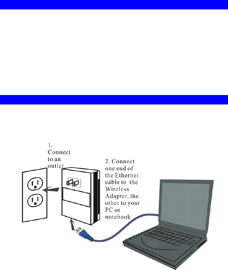
Hardware Connection
1. Connect the Wireless 802.11b/g Portable Router to a power outlet.
2. Connect one end of the Ethernet cable to the Wireless 802.11b/g Portable Router, the other
end to your PC or notebook.
2
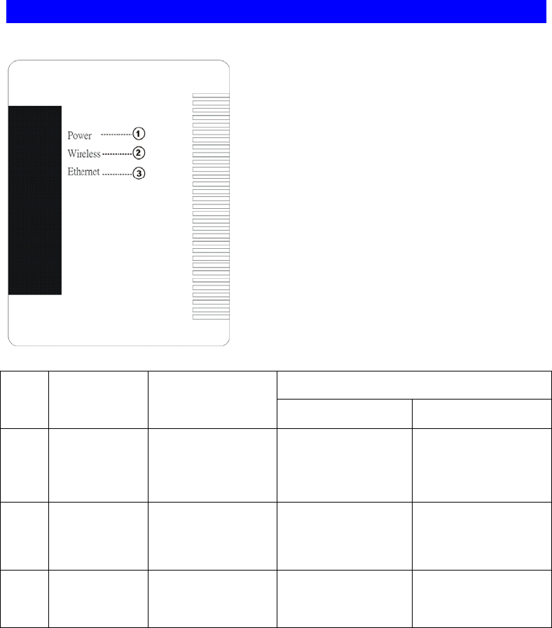
LED Indicators
Front Panel: (LED Indicators)
Status
LED indicator Color
Solid Flashing
1 Power Green Turns solid Green
when the power is
applied to this
device.
NA
2 Wireless Blue Turns solid Blue
when the power is
applied to this
device.
Receiving/
Sending data
3 Ethernet Green Turns solid Green
when an Ethernet
cable is connected.
Receiving/
Sending data
3
About the Operation Modes
This device provides four operational applications with Portable Router, Bridge, Client (Ad-
hoc) and Client (Infrastructure) modes, which are mutually exclusive.
This device is shipped with configuration that is functional right out of the box. If you want to
change the settings in order to perform more advanced configuration or even change the mode
of operation, you can use the web-based utility provided by the manufacturer as described in
the following sections.
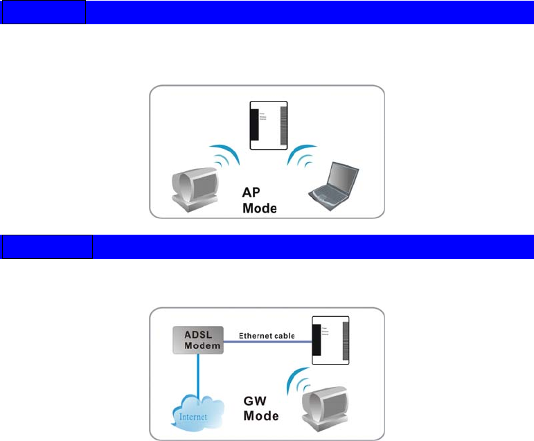
AP Mode
When acting as an access point, this device connects all the stations (PC/notebook with
wireless network adapter) to a wired network. All stations can have the Internet access if only
the Access Point has the Internet connection.
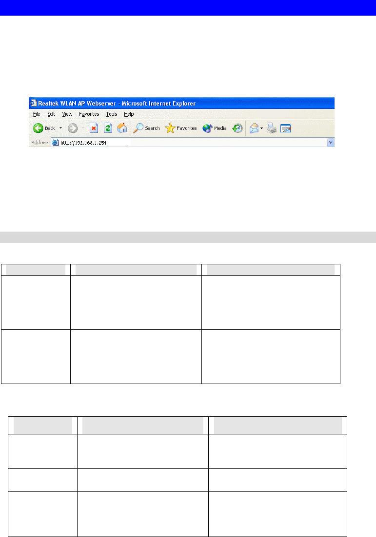
GW Mode
When GW mode is selected, the AP will enter the gateway mode. And the wireless connection
will be set up from a point-to-point local LAN into a point-to-multipoint WAN.
4
Configuration
Login
1. Start your computer. Connect an Ethernet cable between your computer and the Wireless
Portable Router.
2. Make sure your wired station is set to the same subnet as the Wireless Portable Router,
i.e. 192.168.1.254
3. Start your WEB browser. In the Address box, enter the following:
HTTP://192.168.1.254
The configuration menu is divided into four categories: Status, Wireless, TCP/IP, and
Other settings. Click on the desired setup item to expand the page in the main
navigation page. The setup pages covered in this utility are described below.
No username and password required for the fist login, however, you can set up a set of
username and password for the future security, for detailed configuration, please refer to the
Password in the later section of Configuration.
Common Connection Types
Cable Modems
Type Details ISP Data required
Dynamic
IP Address Your IP Address is allocated
automatically, when you
connect to you ISP.
Usually, none.
However, some ISP's may
require you to use a particular
Hostname, Domain name, or
MAC (physical) address.
Static (Fixed)
IP Address Your ISP allocates a
permanent IP Address to you. IP Address allocated to you.
Some ISP's may also require
you to use a particular
Hostname, Domain name, or
MAC (physical) address.
DSL Modems
Type Details ISP Data required
Dynamic
IP Address Your IP Address is allocated
automatically, when you
connect to you ISP.
None.
Static (Fixed)
IP Address Your ISP allocates a
permanent IP Address to you. IP Address allocated to you.
PPPoE You connect to the ISP only
when required. The IP address
is usually allocated
automatically.
User name and password.

5
PPTP Mainly used in Europe.
You connect to the ISP only
when required. The IP address
is usually allocated
automatically, but may be
Static (Fixed).
• PPTP Server IP Address.
• User name and password.
• IP Address allocated to
you, if Static (Fixed).
Other Modems (e.g. Broadband Wireless)
Type Details ISP Data required
Dynamic
IP Address Your IP Address is allocated
automatically, when you
connect to you ISP.
None.
Static (Fixed)
IP Address Your ISP allocates a permanent
IP Address to you. IP Address allocated to you.
6
Configuration via Web
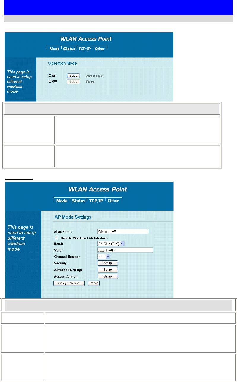
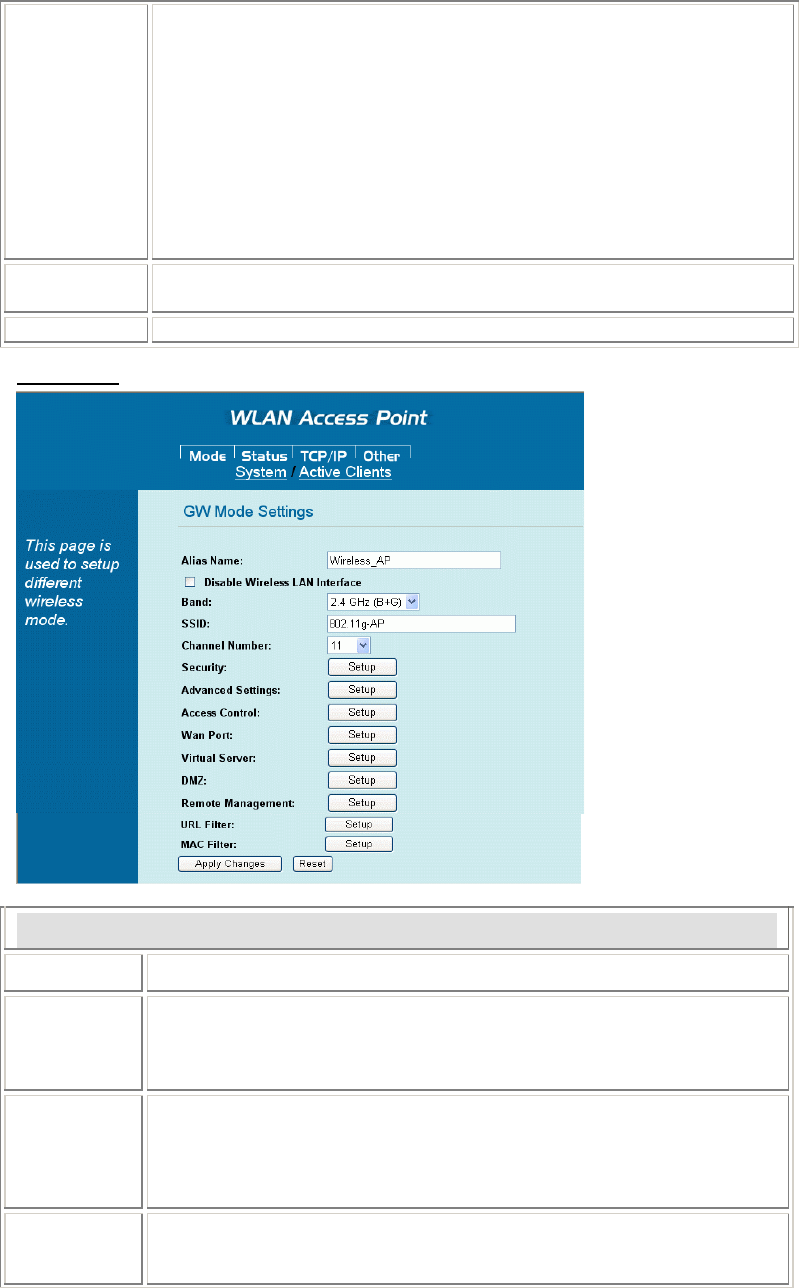
Wireless Mode
Select a wireless mode and then click the Setup button to enter its configuration page.
Wireless Mode
AP When acting as an access point, this device connects all the stations
(PC/notebook with wireless network adapter) to a wired network.
All stations can have the Internet access if only the Access Point
has the Internet connection.
GW Select GW will enter the gateway mode. This means that the
wireless connection will be set up from a point-to-point wireless
LAN into a point-to-multipoint WAN.
AP Mode
AP Mode Settings
Alias Name Display the name of this device.
Disable
Wireless
LAN
Interface
Check the box to disable the Wireless LAN Interface, by so doing, you
won’t be able to make wireless connection with this Access Point in the
network you are located. In other words, this device will not be visible by
any wireless station.
Band You can choose one mode of the following you need.
2.4GHz (B): 802.11b supported rate only.
2.4GHz (G): 802.11g supported rate only.
2.4GHz (B+G): 802.11b supported rate and 802.11g supported rate.
7
The default is 2.4GHz (B+G) mode.
SSID The SSID differentiates one WLAN from another, therefore, all access
points and all devices attempting to connect to a specific WLAN must use
the same SSID. It is case-sensitive and must not exceed 32 characters. A
device will not be permitted to join the BSS unless it can provide the unique
SSID. An SSID is also referred to as a network name because essentially it is
a name that identifies a wireless network.
Channel
Number Allow user to set the channel manually or automatically.
If set channel manually, just select the channel you want to specify.
If “Auto” is selected, user can set the channel range to have the Wireless
Portable Router automatically survey and choose the channel with best
situation for communication.
The number of channels supported depends on the region of this Access
Point. All stations communicating with the Access Point must use the same
channel.
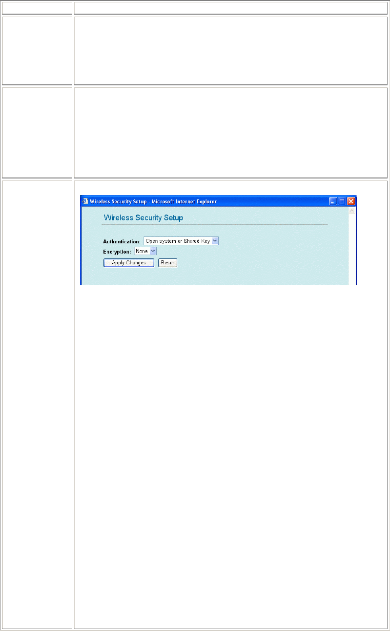
Security Click the Setup button to enter the Security setup page.
Authentication: Select an Authentication from the pull-down list including
Open system or Shared Key, Open System, Open System with 802.1x,
Shared Key, WPA-RADIUS, WPA-PSK, WPA2-RADIUS and WPA2-
PSK.
Encryption: Select the type of encryption from the pull-down list either non
or WEP.
Use 802.1x Authentication: Select 64bit or 128bit Encryption.
Select HEX if you are using hexadecimal numbers (0-9, or A-F). Select
ASCII if you are using ASCII characters (case-sensitive).
Ten hexadecimal digits or five ASCII characters are needed if 64-bit
WEP is used; 26 hexadecimal digits or 13 ASCII characters are needed if
128-bit WEP is used.
Pre-Shared Key Format: Select Passphrase or Hex (64 characters)
Pre-Shared Key: Pre-Shared-Key serves as a password. Users may key in a
8 to 63 characters string to set the password or leave it blank, in which the
802.1x Authentication will be activated. Make sure the same password is
used on client's end.
There are two formats for choice to set the Pre-shared key, i.e. Passphrase
and Hex. If Hex is selected, users will have to enter a 64 characters string.
For easier configuration, the Passphrase (at least 8 characters) format is
recommended.
Group Key Life Time: Enter the number of seconds that will elapse before
the group key change automatically. The default is 86400 seconds.
Enable Pre-Authentication: The two most important features beyond WPA
to become standardized through 802.11i/WPA2 are: pre-authentication,
which enables secure fast roaming without noticeable signal latency.
Preauthentication provides a way to establish a PMK security association
b
efore a client associates. The advanta
g
e is that the client reduces the time
8
that it's disconnected to the network.
Authentication RADIUS Server: RADIUS is an authentication,
authorization and accounting client-server protocol. The client is a Network
Access Server that desires to authenticate its links. The server is a server that
has access to a user database with authentication information.
Port: Enter the RADIUS Server’s port number provided by your ISP. The
default is 1812.
IP Address: Enter the RADIUS Server’s IP Address provided by your ISP.
Password: Enter the password that the AP shares with the RADIUS Server.
Enable Accounting: Check to enable this function.
Accounting RADIUS Server: Port: Enter the RADIUS Server’s port
number provided by your ISP. The default is 1812.
IP Address: Enter the RADIUS Server’s IP Address provided by your ISP.
Password: Enter the password that the AP shares with the RADIUS Server.
Apply Changes: Click to save and apply the current settings.
Reset: Click to clear and reset the current settings.
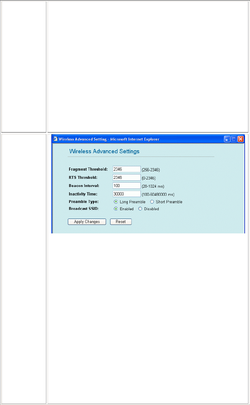
Advanced
Settings
Fragment Threshold: Fragmentation mechanism is used for improving the
efficiency when high traffic flows along in the wireless network. If your
802.11g Wireless LAN PC Card often transmit large files in wireless
network, you can enter new Fragment Threshold value to split the packet.
The value can be set from 256 to 2346. The default value is 2346.
RTS Threshold: RTS Threshold is a mechanism implemented to prevent the
“Hidden Node” problem. “Hidden Node” is a situation in which two
stations are within range of the same Access Point, but are not within range
of each other. Therefore, they are hidden nodes for each other. When a
station starts data transmission with the Access Point, it might not notice that
the other station is already using the wireless medium. When these two
stations send data at the same time, they might collide when arriving
simultaneously at the Access Point. The collision will most certainly result
in a loss of messages for both stations.
Thus, the RTS Threshold mechanism provides a solution to prevent data
collisions. When you enable RTS Threshold on a suspect “hidden station”,
this station and its Access Point will use a Request to Send (RTS). The
station will send an RTS to the Access Point, informing that it is going to
transmit the data. Upon receipt, the Access Point will respond with a CTS
message to all station within its range to notify all other stations to defer
transmission. It will also confirm the requestor station that the Access Point
has reserved it for the time-frame of the requested transmission.
9
If the “Hidden Node” problem is an issue, please specify the packet size. The
RTS mechanism will be activated if the data size exceeds the value you set..
The default value is 2347.
Warning: Enabling RTS Threshold will cause redundant network
overhead that could negatively affect the throughput performance instead
of providing a remedy.
This value should remain at its default setting of 2347. Should you encounter
inconsistent data flow, only minor modifications of this value are recommended.
Beacon Interval: Beacon Interval is the amount of time between beacon
transmissions. Before a station enters power save mode, the station needs the
beacon interval to know when to wake up to receive the beacon (and learn
whether there are buffered frames at the access point).
Inactivity Time:
Data Rate: By default, the unit adaptively selects the highest possible rate
for transmission. Select the basic rates to be used among the following
options: Auto, 1, 2, 5.5, 11or 54 Mbps. For most networks the default setting
is Auto which is the best choice. When Auto is enabled the transmission rate
will select the optimal rate. If obstacles or interference are present, the
system will automatically fall back to a lower rate.
Preamble Type: A preamble is a signal used in wireless environment to
synchronize the transmitting timing including Synchronization and Start
frame delimiter. (Note: If you want to change the Preamble type into Long
or Short, please check the setting of AP)
Broadcast SSID: Enable: This wireless AP will broadcast its SSID to stations.
Disable: This wireless AP will not broadcast its SSID to stations. If stations want to connect
to this wireless AP, this AP’s SSID should be known in advance to make a connection.
Apply Changes: Click to save and apply the current setting.
Reset: Click to clear and reset the current settings.
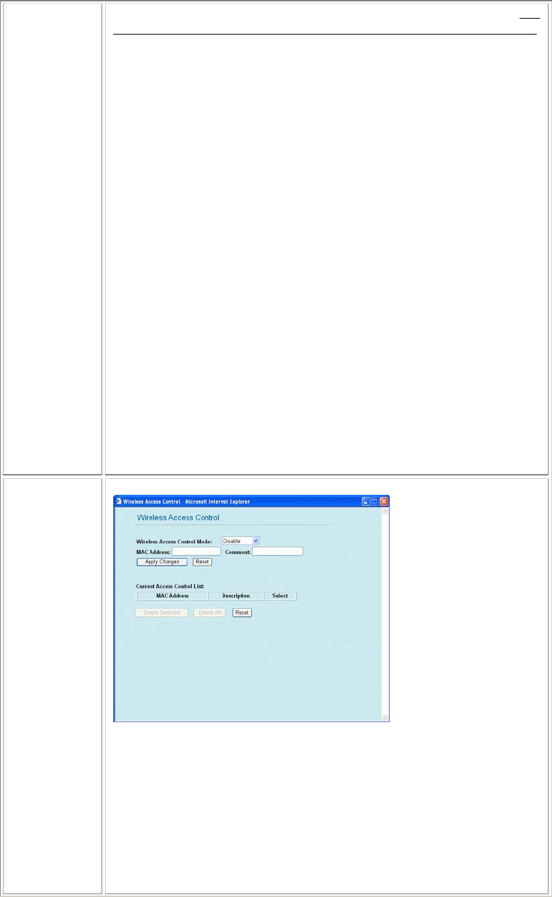
Access
Control Click to enter the Access Control screen.
Wireless Access Control Mode: Select the Access Control Mode from the
pull-down menu.
• Disable: Select to disable Wireless Access Control Mode.
• Allow Listed: Only the stations shown in the table can associate
with the AP.
Deny Listed: Stations shown in the table won’t be able to associate with the
AP.
MAC Address: Enter the MAC Address of a station that is allowed to
access this Access Point.
Comment: You ma
y
enter u
p
to 20 characters as a remark to the
p
revious
10
MAC Address.
Apply Changes: Press to save the new settings on the screen.
Reset: Press to discard the data you have entered since last time you press
Apply Change.
Delete Selected: To delete clients from access to this Access Point, you
may firstly check the Select checkbox next to the MAC address and
Comments, and press Delete Selected.
Delete All: To delete all the clients from access to this Access Point, just
press Delete All without selecting the checkbox.
Reset: If you have made any selection, press Reset will clear all the select
mark.
Apply
Changes Click to save the current settings.
Reset Click to reset this page.
GW mode
GW Mode Settings
Alias Name Display the name of this device.
Disable
Wireless
LAN
Interface
Check the box to disable the Wireless LAN Interface, by so doing, you
won’t be able to make wireless connection with this Portable Router in the
network you are located. In other words, this device will not be visible by
any wireless station.
Band You can choose one mode of the following you need.
2.4GHz (B): 802.11b supported rate only.
2.4GHz (G): 802.11g supported rate only.
2.4GHz (B+G): 802.11b supported rate and 802.11g supported rate.
The default is 2.4GHz (B+G) mode.
SSID The SSID differentiates one WLAN from another, therefore, all access
points and all devices attempting to connect to a specific WLAN must use
the same SSID. It is case-sensitive and must not exceed 32 characters. A
11
device will not be permitted to join the BSS unless it can provide the unique
SSID. An SSID is also referred to as a network name because essentially it is
a name that identifies a wireless network.
Channel
Number Allow user to set the channel manually or automatically.
If set channel manually, just select the channel you want to specify.
If “Auto” is selected, user can set the channel range to have the Wireless
Portable Router automatically survey and choose the channel with best
situation for communication.
The number of channels supported depends on the region of this Portable
Router. All stations communicating with the Portable Router must use the
same channel.
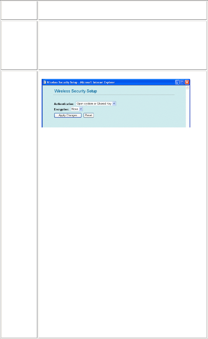
Security Click the Setup button to enter the Security setup page.
Authentication: Select an Authentication from the pull-down list including
Open system or Shared Key, Open System, Open System with 802.1x,
Shared Key, WPA-RADIUS, WPA-PSK, WPA2-RADIUS and WPA2-
PSK.
Encryption: Select the type of encryption from the pull-down list either non
or WEP.
Use 802.1x Authentication: Select 64bit or 128bit Encryption.
Select HEX if you are using hexadecimal numbers (0-9, or A-F). Select
ASCII if you are using ASCII characters (case-sensitive).
Ten hexadecimal digits or five ASCII characters are needed if 64-bit
WEP is used; 26 hexadecimal digits or 13 ASCII characters are needed if
128-bit WEP is used.
Pre-Shared Key Format: Select Passphrase or Hex (64 characters)
Pre-Shared Key: Pre-Shared-Key serves as a password. Users may key in a
8 to 63 characters string to set the password or leave it blank, in which the
802.1x Authentication will be activated. Make sure the same password is
used on client's end.
There are two formats for choice to set the Pre-shared key, i.e. Passphrase
and Hex. If Hex is selected, users will have to enter a 64 characters string.
For easier configuration, the Passphrase (at least 8 characters) format is
recommended.
Group Key Life Time: Enter the number of seconds that will elapse before
the group key change automatically. The default is 86400 seconds.
Enable Pre-Authentication: The two most important features beyond WPA
to become standardized through 802.11i/WPA2 are: pre-authentication,
which enables secure fast roaming without noticeable signal latency.
Preauthentication provides a way to establish a PMK security association
before a client associates. The advantage is that the client reduces the time
that it's disconnected to the network.
Authentication RADIUS Server: RADIUS is an authentication,
authorization and accounting client-server protocol. The client is a Network
Access Server that desires to authenticate its links. The server is a server that
12
has access to a user database with authentication information.
Port: Enter the RADIUS Server’s port number provided by your ISP. The
default is 1812.
IP Address: Enter the RADIUS Server’s IP Address provided by your ISP.
Password: Enter the password that the AP shares with the RADIUS Server.
Enable Accounting: Check to enable this function.
Accounting RADIUS Server
Port: Enter the RADIUS Server’s port number provided by your ISP. The
default is 1812.
IP Address: Enter the RADIUS Server’s IP Address provided by your ISP.
Password: Enter the password that the AP shares with the RADIUS Server.
Apply Changes: Click to save and apply the current settings.
Reset: Click to clear and reset the current settings.
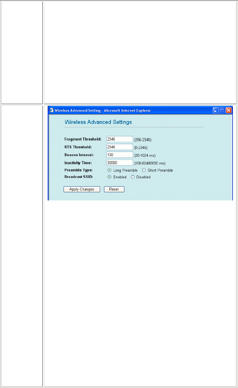
Advanced
Settings
Fragment Threshold: Fragmentation mechanism is used for improving the
efficiency when high traffic flows along in the wireless network. If your
Wireless Router often transmits large files in wireless network, you can
enter new Fragment Threshold value to split the packet. The value can be
set from 256 to 2346. The default value is 2346.
RTS Threshold: RTS stands for “Request to Send”. This parameter controls
what size data packet the low level RF protocol issues to an RTS packet. The
default is 2346. The RTS Threshold mechanism provides a solution to
prevent data collisions. When you enable RTS Threshold on a suspect
“hidden station”, this station and its Portable Router will use a Request to
Send (RTS). The station will send an RTS to the Access Point, informing
that it is going to transmit the data. Upon receipt, the Access Point will
respond with a CTS message to all station within its range to notify all other
stations to defer transmission. It will also confirm the requestor station that
the Access Point has reserved it for the time-frame of the requested
transmission.
Beacon Interval: Enter a value between 20-1024 milliseconds. The Beacon
Interval value indicates the frequency interval of the beacon. A beacon is a
packet broadcast by the Router to synchronize the wireless network. The
default value is 100.
Inactivity Time:
Data Rate: By default, the unit adaptively selects the highest possible rate
for transmission. Select the basic rates to be used among the following
options: Auto, 1, 2, 5.5, 11or 54 Mbps. For most networks the default setting
is Auto which is the best choice. When Auto is enabled the transmission
rate will select the o
p
ti
m
al rate. If obstacles or interference are
p
resent
,
the
13
system will automatically fall back to a lower rate.
Preamble Type: A preamble is a signal used in wireless environment to
synchronize the transmitting timing including Synchronization and Start
frame delimiter. (Note: If you want to change the Preamble type into Long
or Short, please check the setting of AP)
Broadcast SSID
Enable: This Wireless Router will broadcast its SSID to stations.
Disable: This Wireless Router will not broadcast its SSID to stations. If stations
want to connect to this Wireless Router, this Wireless Router’s SSID should be
known in advance to make a connection.
Apply Changes: Click to save and apply the current setting.
Reset: Click to clear and reset the current settings.
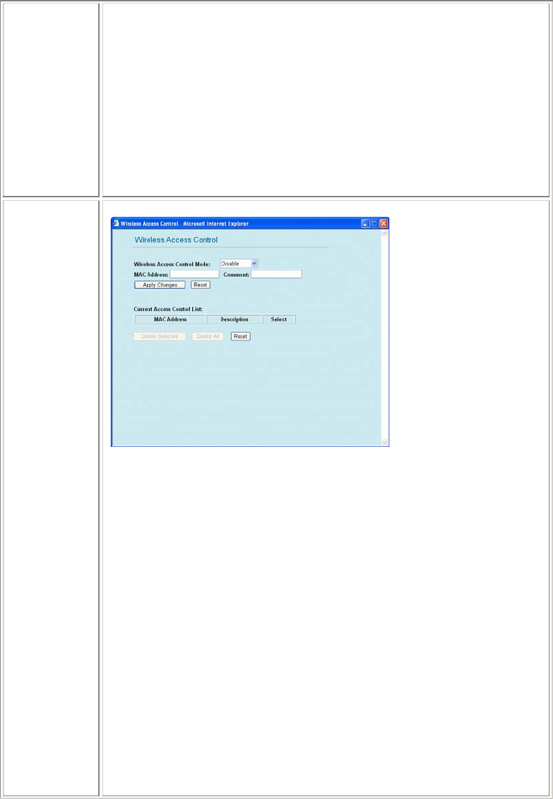
Access
Control Click to enter the Access Control screen.
Wireless Access Control Mode: Select the Access Control Mode from the
pull-down menu.
• Disable: Select to disable Wireless Access Control Mode.
• Allow Listed: Only the stations shown in the table can associate
with the Wireless Router.
Deny Listed: Stations shown in the table won’t be able to associate with the
Wireless Router.
MAC Address: Enter the MAC Address of a station that is allowed to
access this Access Point.
Comment: You may enter up to 20 characters as a remark to the previous
MAC Address.
Apply Changes: Press to save the new settings on the screen.
Reset: Press to discard the data you have entered since last time you press
Apply Change.
Delete Selected: To delete clients from access to this Access Point, you
may firstly check the Select checkbox next to the MAC address and
Comments, and press Delete Selected.
Delete All: To delete all the clients from access to this Access Point, just
press Delete All without selecting the checkbox.
Reset: If you have made any selection, press Reset will clear all the select
mark.
14
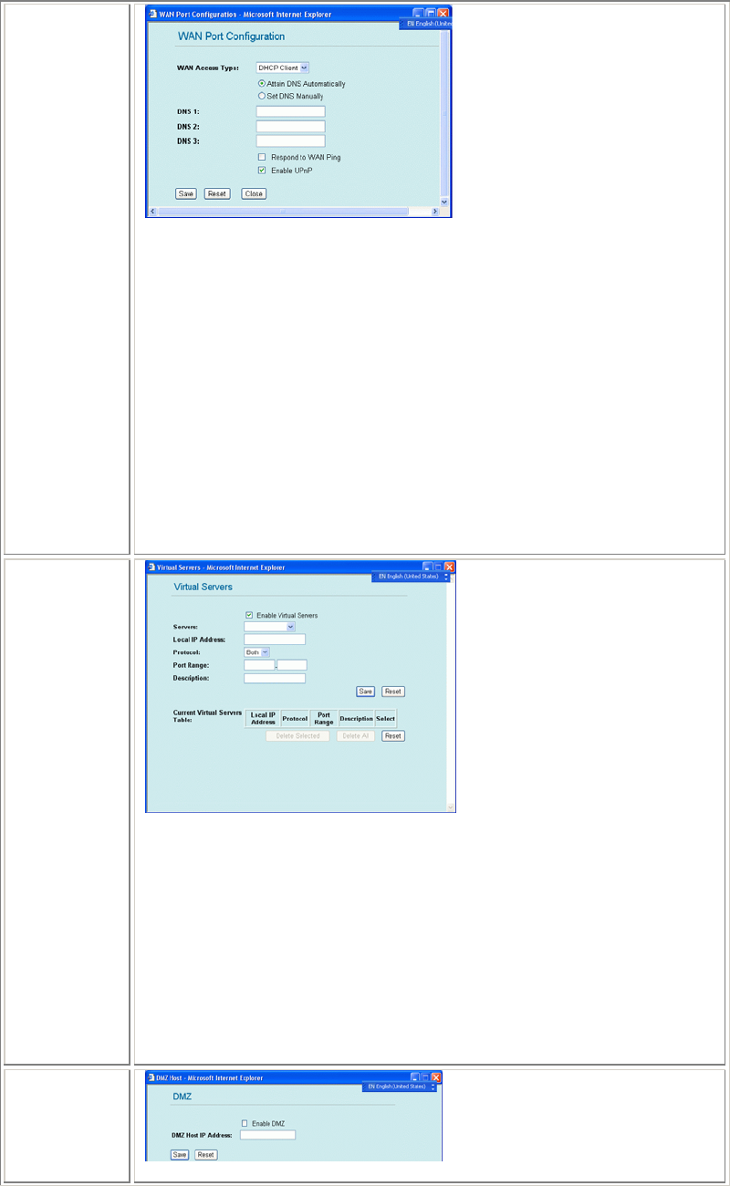
WAN Port
WAN Access Type: Select the WAN access type (Static IP, DHCP, PPPoE
and PPTP) from the pull-down menu.
Attain DNS Automatically:
Set DNS Manually:
DNS1~3: Enter the DNS server IP address(es) provided by your ISP, or you
can specify your own preferred DNS server IP address(es).
DNS 1 and DNS 2 servers are optional. You can enter another DNS server’s
IP address as a backup. DNS 1 and DNS 2 servers will be used when the
DNS 1 server fails.
Respond to WAN Ping:
Enable UPnP: Universal Plug and Play (UPnP) allows Windows Me and XP
to automatically configure the Router for various Internet applications, such
as gaming and videoconferencing. If you want to use UPnP, select Enable
UPnP.
Save: Click to save and apply the current settings.
Close: click to exit the current settings.
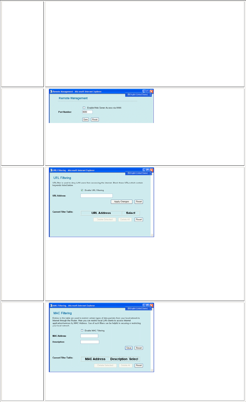
Virtual Server
Enable Virtual Servers: Check to enable the Virtual Server function.
Local IP Address: Enter the Local Server’s IP address.
Protocol: Select the protocol (TCP, UDP or Both) used to the remote system
or service.
Port Range: For TCP and UDP Services, enter the beginning of the range of
port numbers used by the service. If the service uses a single port number,
enter it in both the start and finish fields.
Description: You may key in a description for the local IP address.
Save: Click to save and apply the current settings.
Reset: Click to clear and rest the current settings.
Current Virtual Servers table: Shows the current virtual servers
information.
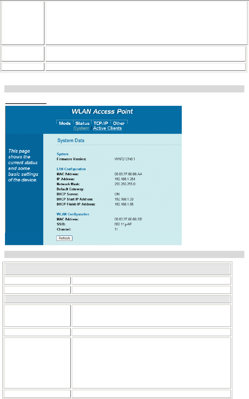
DMZ
Enable DMZ: If the DMZ Hos
t
Function is enabled
,
it means that
y
ou set u
p
15
DMZ host at a particular computer to be exposed to the Internet so that some
applications/software, especially Internet / online game can have two-way
connections.
DMZ Host IP Address: Enter the IP address of a particular host in your
LAN which will receive all the packets originally going to the WAN
port/Public IP address above.
Save: Click to save the current settings.
Reset: Click to restore to the default values.
Note: You need to give your LAN PC clients a fixed/static IP address for
DMZ to work properly.
Remote
Management
Enable Web Server Access via WAN: to permit remote access of the Router,
from outside the local network, select to enable.
Otherwise, keep the default setting, Disabled.
Port Number: Enter the port number that will be open to outside access.
Save: Click to save the current settings.
Reset: Click to restore to the default values.
URL Filter
Enable URL Filtering: Click to enable the URL filtering function
URL Address: You can block websites with specific URL addresses.
Apply Changes: Click to save the current settings
Reset: Click to clear the current settings
Current Filter Table: Shows the current URL address status.
Delete Selected: Select the unwanted URL addresses and then click the
Delete Selected button to eliminate them
Delete All: Click to delete all the URL addresses in the tale
Reset: Click to clear the current settings
MAC Filter
Enable MAC Filtering:
MAC Address: For MAC filtering, enter the 12-digit MAC address in the
appropriate MAC field
Save: Click to save the current settings.
16
Reset: Click to restore to the default values.
Current Filter Table: Shows
Delete Selected: Select the unwanted MAC addresses and then click the
Delete Selected button to eliminate them
Delete All: Click to delete all the MAC addresses in the tale
Reset: Click to clear the current settings
Apply
Changes Click to save the current settings.
Reset Click to reset this page.
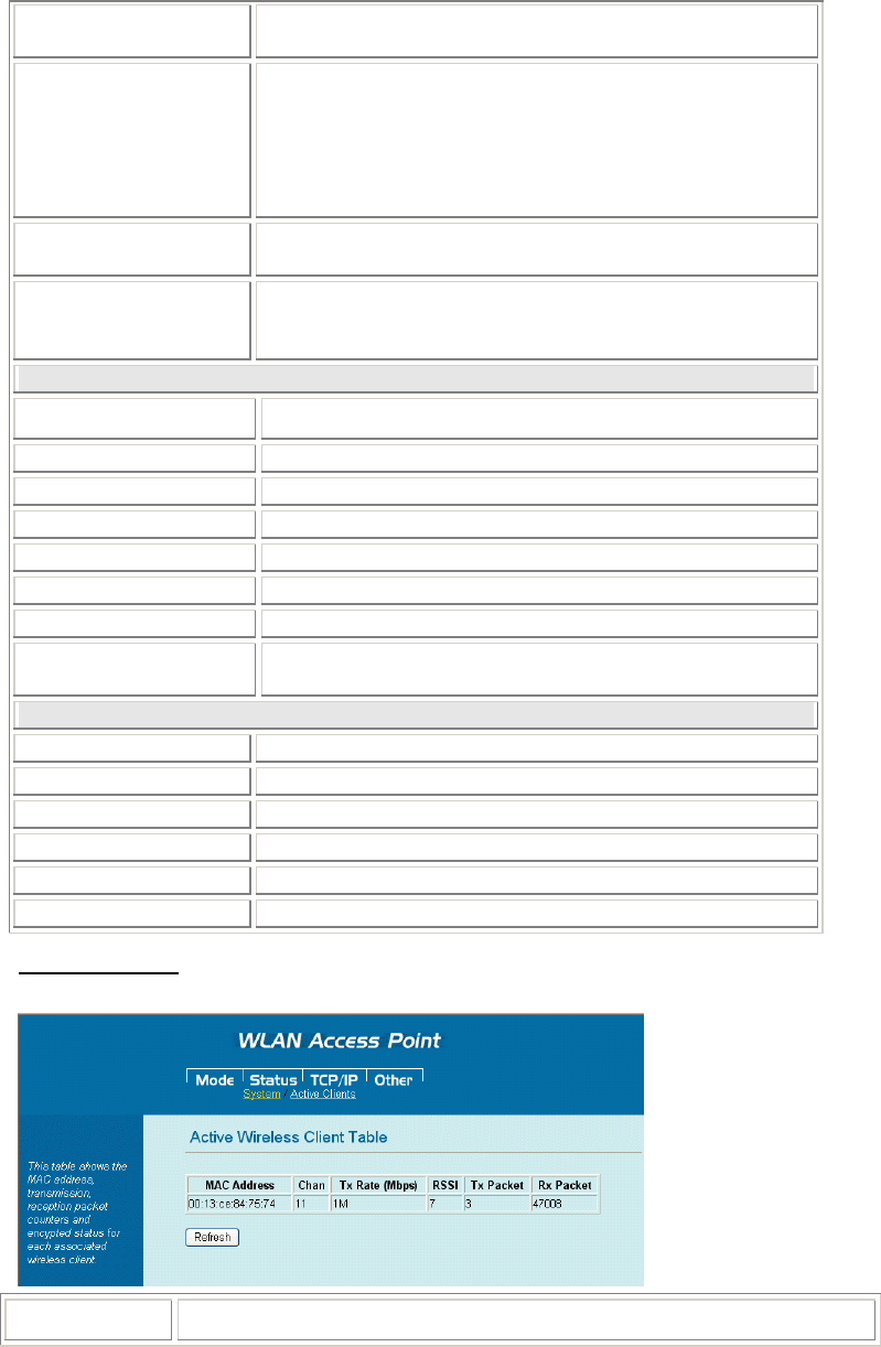
Status
System Data
System Data
System Data
Uptime The time period since the device was up.
Firmware Version The current version of the firmware installed in this device.
Wireless
Mode There are four modes supported, Access Point, Client (Ad-
hoc and Infrastructure), WDS Bridge and WDS repeater.
The default mode is Access Point.
Band Displays the current band in use.
SSID The SSID differentiates one WLAN from another, therefore,
all access points and all devices attempting to connect to a
specific WLAN must use the same SSID. It is case-sensitive
and must not exceed 32 characters. A device will not be
permitted to join the BSS unless it can provide the unique
SSID. An SSID is also referred to as a network name because
essentially it is a name that identifies a wireless network.
Channel Number The number of channels su
pp
orted de
p
ends on the re
g
ion of
17
this Access Point. All stations communicating with the Access
Point must use the same channel.
Encryption WEP Encryption (Wired Equivalent Privacy) is set to
Disabled by default. When WEP is enabled, data packet is
encrypted before being transmitted. The WEP prevents data
packets from being eavesdropped by unrelated people. By
using WEP data encryption, there may be a significant
degradation of the data throughput on the wireless link.
Associated Clients Displays the total number of clients associated to this AP. You
can have up to 64 clients to associate to this Access Point.
BSSID BSSID displays the ID of current BSS, which uniquely
identifies each BSS. In AP mode, this value is the MAC
address of this Access Point.
LAN Configuration
Connection Method Shows the currently used connection method.
Physical Address Shows the MAC address of this device.
IP Address Shows the LAN IP address.
Network Mask Shows the LAN subnet mask.
Default Gateway Shows the LAN default gateway.
DHCP Server Shows the current DHCP Server status.
DHCP Start IP Address Shows the DHCP Start IP address.
DHCP Finish IP
Address Shows the DHCP Finish IP address.
Internet Configuration
Connection Method Shows the current used internet connection method.
Physical Address Shows the MAC address of this device.
IP Address Shows the Internet IP address
Network Mask Shows the subnet mask IP address.
Default Gateway Shows the Internet default gateway.
Refresh Click to refresh the current system data.
Active Clients
Displays the wireless clients that are currently connecting with this Wireless Portable Router.
Refresh Click to refresh the Active Wireless Client table.
18
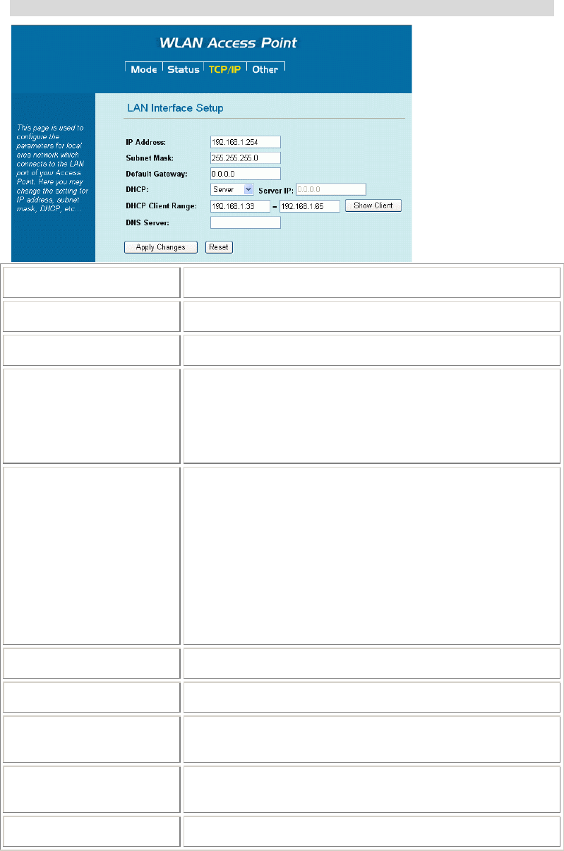
TCP/IP
IP Address Default: 192.168.1.254 (this is the local address of this Router)
Subnet Mask Default: 255.255.255.0
Default Gateway Shows the default gateway IP address.
DHCP Disable: Select to disable this Router to distribute IP Addresses
(Disabled)
Server: Select to enable this Router to distribute IP Addresses
(DHCP Server). And the following field will be activated for
you to enter the starting IP Address
DHCP Client Range The starting address of this local IP network address pool.
The pool is a piece of continuous IP address segment. Keep
the default value 192.168.1.1 should work for most cases.
• Maximum: 253. Default value 253 should work
for most cases.
Note: If “Continuous IP address poll starts” is set at
192.168.1.1 and the “Number of IP address in pool” is 253,
the device will distribute IP addresses from 192.168.1.1 to
192.168.1.253 to all the computers in the network that request
IP addresses from DHCP server (Router)
Show Client Click to show Active DHCP Client table.
DNS Server Enter the Domain Name Service IP address.
Clone MAC Address You can specify the MAC address of your Access Point to
replace the factory setting.
Apply Changes After completing the settings on this page, click to save the
settings.
Reset Click to restore to default values.
19
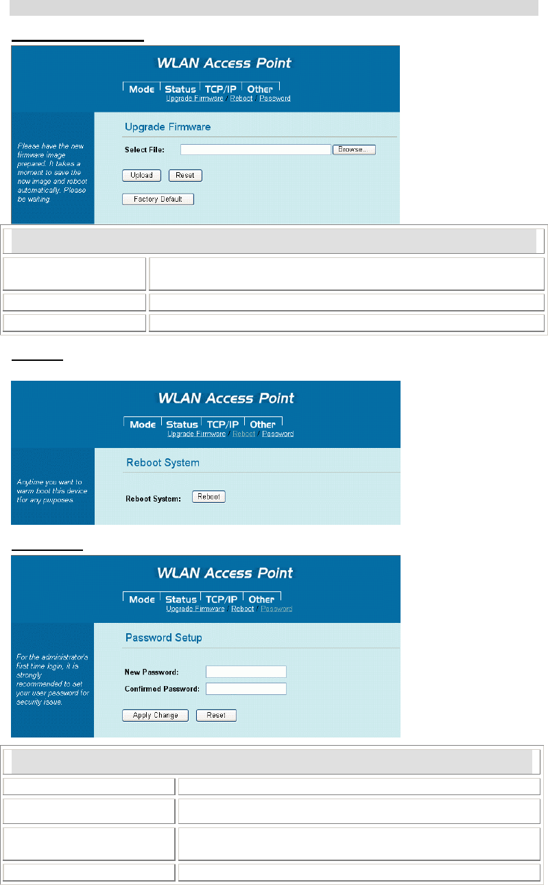
Other
Upgrade Firmware
Upgrade Firmware
Browse Click the Browse button, find and open the firmware file (the
browser will display to correct file path).
Upload Click the Upload button to perform.
Reset Clic the Reset button to restore default values.
Reboot
Click the Reboot button to reboot the hardware system.
Password
Password Setup
New Password Maximum input is 36 alphanumeric characters (case sensitive)
Confirmed Password Key in the password again to confirm.
Apply Change After completing the settings on this page, click the Apply
Change button to save the settings.
Reset Click the Reset button to clear settings.

20
Chapter 4: PC Configuration
Overview
For each PC, the following may need to be configured:
• TCP/IP network settings
• Internet Access configuration
• Wireless configuration
Windows Clients
This section describes how to configure Windows clients for Internet access via the Wireless
Router.
The first step is to check the PC's TCP/IP settings.
The Wireless Router uses the TCP/IP network protocol for all functions, so it is essential that
the TCP/IP protocol be installed and configured on each PC.
TCP/IP Settings - Overview
If using the default Wireless Router settings, and the default Windows
TCP/IP settings, no changes need to be made.
• By default, the Wireless Router will act as a DHCP Server, automatically providing a
suitable IP Address (and related information) to each PC when the PC boots.
• For all non-Server versions of Windows, the default TCP/IP setting is to act as a DHCP
client.
If using a Fixed (specified) IP address, the following changes are
required:
• The Gateway must be set to the IP address of the Wireless Router
• The DNS should be set to the address provided by your ISP.
21
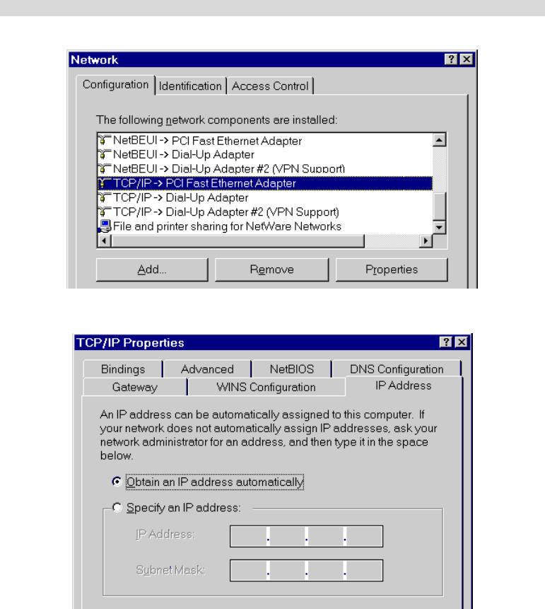
Checking TCP/IP Settings - Windows 98/ME:
1. Select Control Panel - Network. You should see a screen like the following:
1. Select the TCP/IP protocol for your network card.
2. Click on the Properties button. You should then see a screen like the following.
Ensure your TCP/IP settings are correct, as follows:
Using DHCP
To use DHCP, select the radio button Obtain an IP Address automatically. This is the default
Windows setting. Using this is recommended. By default, the Wireless Router will act as a
DHCP Server.
Restart your PC to ensure it obtains an IP Address from the Wireless Router.
Using "Specify an IP Address"
If your PC is already configured, check with your network administrator before making the
following changes:
• On the Gateway tab, enter the Wireless Router's IP address in the New Gateway field and
click Add, as shown below. Your LAN administrator can advise you of the IP Address
they assigned to the Wireless Router.
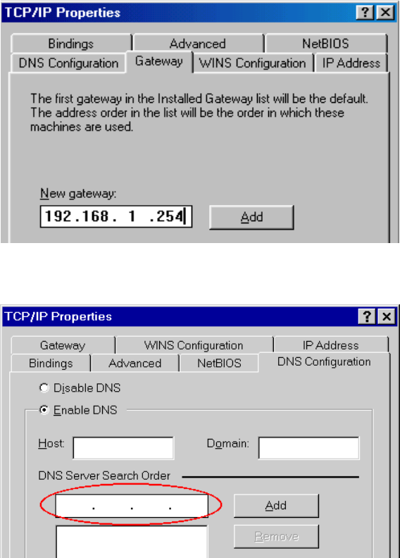
22
• On the DNS Configuration tab, ensure Enable DNS is selected. If the DNS Server Search
Order list is empty, enter the DNS address provided by your ISP in the fields beside the
Add button, then click Add.
23
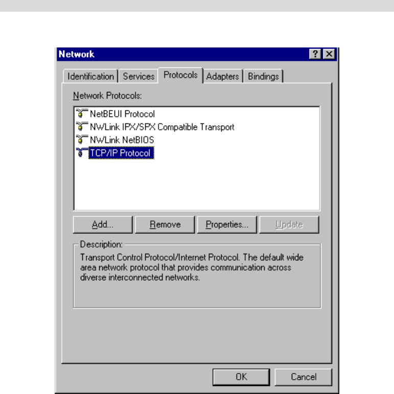
Checking TCP/IP Settings - Windows NT4.0
2. Select Control Panel - Network, and, on the Protocols tab, select the TCP/IP protocol, as
shown below.
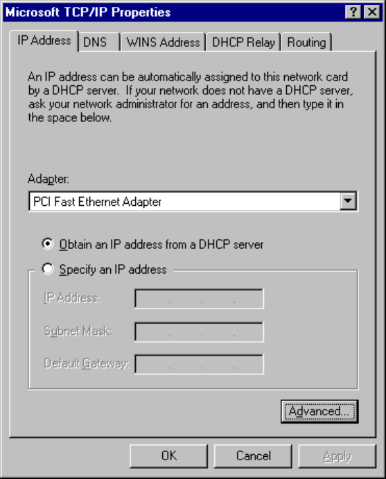
3. Click the Properties button to see a screen like the one below.
24
4. Select the network card for your LAN.
5. Select the appropriate radio button - Obtain an IP address from a DHCP Server or Specify
an IP Address, as explained below.
Obtain an IP address from a DHCP Server
This is the default Windows setting. Using this is recommended. By default, the Wireless
Router will act as a DHCP Server.
Restart your PC to ensure it obtains an IP Address from the Wireless Router.
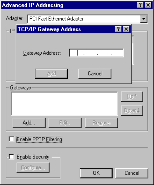
Specify an IP Address
If your PC is already configured, check with your network administrator before making the
following changes.
3. The Default Gateway must be set to the IP address of the Wireless Router. To set this:
• Click the Advanced button on the screen above.
• On the following screen, click the Add button in the Gateways panel, and enter the
Wireless Router's IP address.
• If necessary, use the Up button to make the Wireless Router the first entry in the
Gateways list.
25
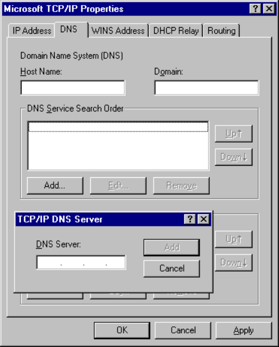
6. The DNS should be set to the address provided by your ISP, as follows:
• Click the DNS tab.
• On the DNS screen, shown below, click the Add button (under DNS Service Search
Order), and enter the DNS provided by your ISP.
26
27
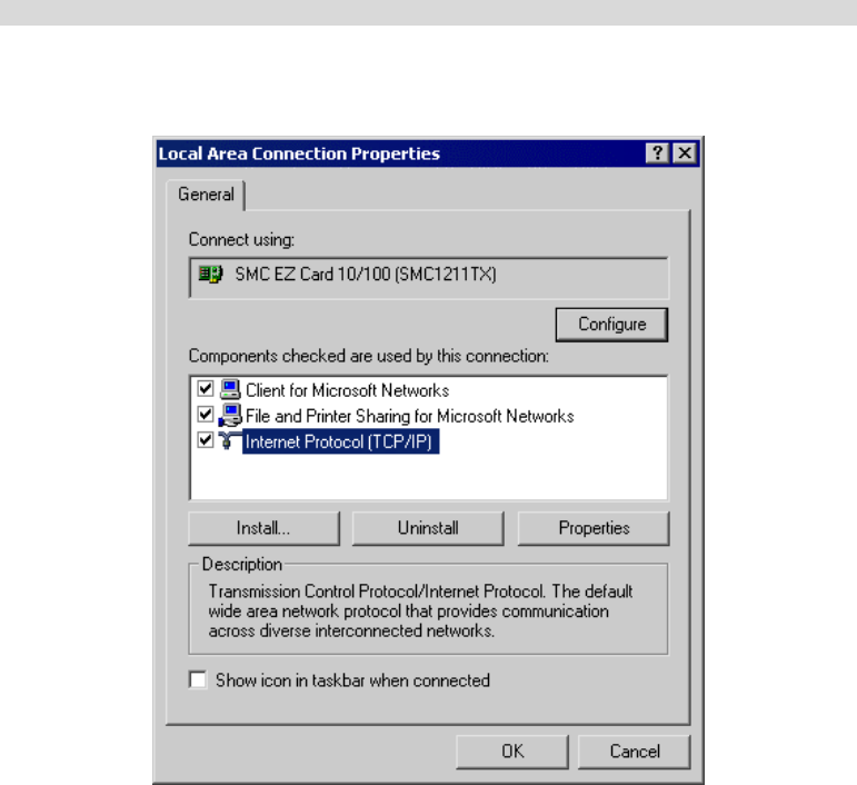
Checking TCP/IP Settings - Windows 2000:
4. Select Control Panel - Network and Dial-up Connection.
7. Right - click the Local Area Connection icon and select Properties. You should see a
screen like the following:
8. Select the TCP/IP protocol for your network card.
9. Click on the Properties button. You should then see a screen like the following.
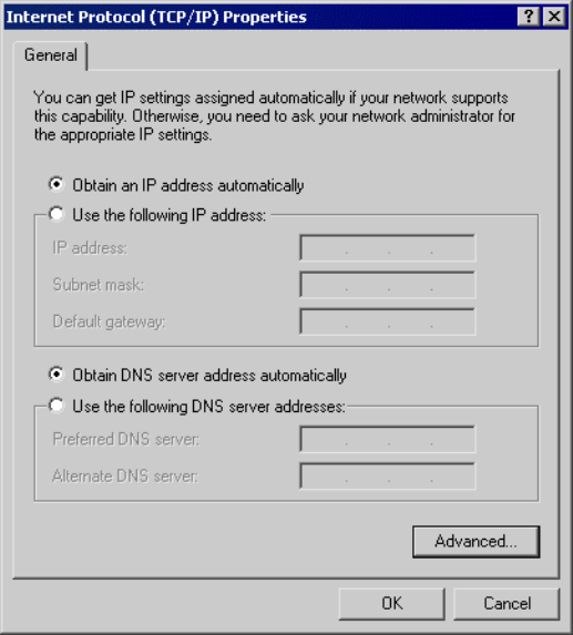
28
10. Ensure your TCP/IP settings are correct, as described below.
Using DHCP
To use DHCP, select the radio button Obtain an IP Address automatically. This is the default
Windows setting. Using this is recommended. By default, the Wireless Router will act as a
DHCP Server.
Restart your PC to ensure it obtains an IP Address from the Wireless Router.
Using a fixed IP Address ("Use the following IP Address")
If your PC is already configured, check with your network administrator before making the
following changes.
• Enter the Wireless Router's IP address in the Default gateway field and click OK. (Your
LAN administrator can advise you of the IP Address they assigned to the Wireless Router.)
• If the DNS Server fields are empty, select Use the following DNS server addresses, and
enter the DNS address or addresses provided by your ISP, then click OK.
29
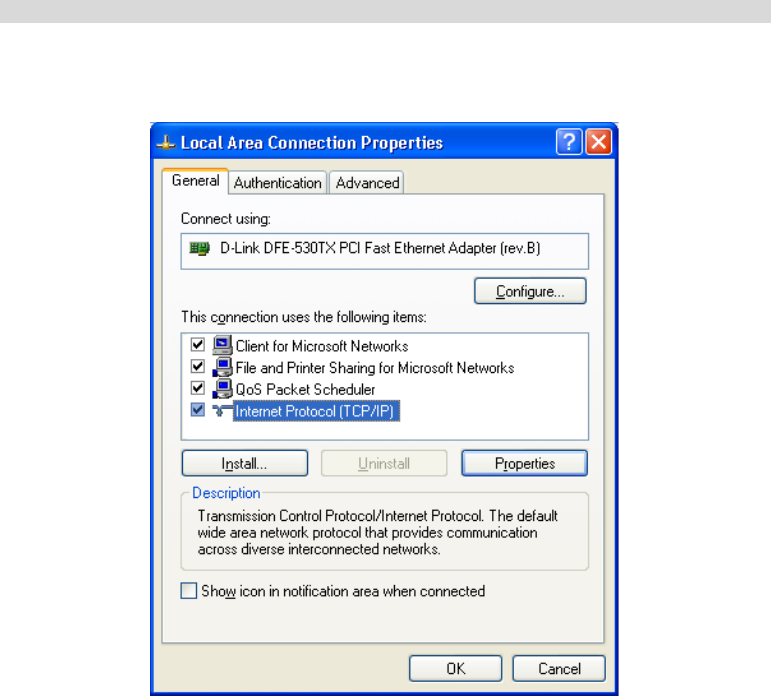
Checking TCP/IP Settings - Windows XP
5. Select Control Panel - Network Connection.
11. Right click the Local Area Connection and choose Properties. You should see a screen
like the following:
12. Select the TCP/IP protocol for your network card.
13. Click on the Properties button. You should then see a screen like the following.
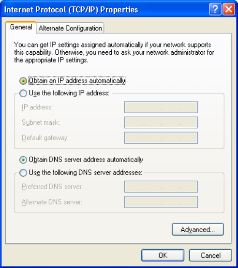
30
14. Ensure your TCP/IP settings are correct.
Using DHCP
To use DHCP, select the radio button Obtain an IP Address automatically. This is the default
Windows setting. Using this is recommended. By default, the Wireless Router will act as a
DHCP Server.
Restart your PC to ensure it obtains an IP Address from the Wireless Router.
Using a fixed IP Address ("Use the following IP Address")
If your PC is already configured, check with your network administrator before making the
following changes.
• In the Default gateway field, enter the Wireless Router's IP address and click OK. Your
LAN administrator can advise you of the IP Address they assigned to the Wireless Router.
• If the DNS Server fields are empty, select Use the following DNS server addresses, and
enter the DNS address or addresses provided by your ISP, then click OK.

31
Internet Access
To configure your PCs to use the Wireless Router for Internet access:
• Ensure that the DSL modem, Cable modem, or other permanent connection is functional.
• Use the following procedure to configure your Browser to access the Internet via the LAN,
rather than by a Dial-up connection.
For Windows 9x/ME/2000
6. Select Start Menu - Settings - Control Panel - Internet Options.
15. Select the Connection tab, and click the Setup button.
16. Select "I want to set up my Internet connection manually, or I want to connect through a
local area network (LAN)" and click Next.
17. Select "I connect through a local area network (LAN)" and click Next.
18. Ensure all of the boxes on the following Local area network Internet Configuration screen
are unchecked.
19. Check the "No" option when prompted "Do you want to set up an Internet mail account
now?"
20. Click Finish to close the Internet Connection Wizard.
Setup is now completed.
For Windows XP
7. Select Start Menu - Control Panel - Network and Internet Connections.
21. Select Set up or change your Internet Connection.
22. Select the Connection tab, and click the Setup button.
23. Cancel the pop-up "Location Information" screen.
24. Click Next on the "New Connection Wizard" screen.
25. Select "Connect to the Internet" and click Next.
26. Select "Set up my connection manually" and click Next.
27. Check "Connect using a broadband connection that is always on" and click Next.
28. Click Finish to close the New Connection Wizard.
Setup is now completed.
Accessing AOL
To access AOL (America On Line) through the Wireless Router, the AOL for Windows
software must be configured to use TCP/IP network access, rather than a dial-up connection.
The configuration process is as follows:
• Start the AOL for Windows communication software. Ensure that it is Version 2.5, 3.0 or
later. This procedure will not work with earlier versions.
• Click the Setup button.
• Select Create Location, and change the location name from "New Locality" to "Wireless
Router".
• Click Edit Location. Select TCP/IP for the Network field. (Leave the Phone Number
blank.)
• Click Save, then OK.
Configuration is now complete.
• Before clicking "Sign On", always ensure that you are using the "Wireless Router"
location.

32
Macintosh Clients
From your Macintosh, you can access the Internet via the Wireless Router. The procedure is as
follows.
8. Open the TCP/IP Control Panel.
29. Select Ethernet from the Connect via pop-up menu.
30. Select Using DHCP Server from the Configure pop-up menu. The DHCP Client ID field
can be left blank.
31. Close the TCP/IP panel, saving your settings.
Note:
If using manually assigned IP addresses instead of DHCP, the required changes are:
• Set the Router Address field to the Wireless Router's IP Address.
• Ensure your DNS settings are correct.
Linux Clients
To access the Internet via the Wireless Router, it is only necessary to set the Wireless Router as
the "Gateway".
Ensure you are logged in as "root" before attempting any changes.
Fixed IP Address
By default, most Unix installations use a fixed IP Address. If you wish to continue using a
fixed IP Address, make the following changes to your configuration.
• Set your "Default Gateway" to the IP Address of the Wireless Router.
• Ensure your DNS (Name server) settings are correct.
To act as a DHCP Client (recommended)
The procedure below may vary according to your version of Linux and X -windows shell.
9. Start your X Windows client.
10. Select Control Panel - Network
11. Select the "Interface" entry for your Network card. Normally, this will be called "eth0".
12. Click the Edit button, set the "protocol" to "DHCP", and save this data.
13. To apply your changes
• Use the "Deactivate" and "Activate" buttons, if available.
• OR, restart your system.
Other Unix Systems
To access the Internet via the Wireless Router:
• Ensure the "Gateway" field for your network card is set to the IP Address of the Wireless
Router.
• Ensure your DNS (Name Server) settings are correct.

33
Wireless Station Configuration
This section applies to all Wireless stations wishing to use the Wireless Router's Access Point,
regardless of the operating system which is used on the client.
To use the Wireless Portable Router in the Wireless Router, each Wireless Station must have
compatible settings, as follows:
Mode The mode must be set to Infrastructure.
SSID (ESSID) This must match the value used on the Wireless Router. The default
value is Untitled
Note! The SSID is case sensitive.
WEP By default, WEP on the Wireless Router is disabled.
• If WEP remains disabled on the Wireless Router, all stations must
have WEP disabled.
• If WEP is enabled on the Wireless Router, each station must use the
same settings as the Wireless Router.
Note:
By default, the Wireless Router will allow both 802.11b and 802.11g connections.

34
Appendix A
Troubleshooting
Overview
This chapter covers some common problems that may be encountered while using the Wireless
Router and some possible solutions to them. If you follow the suggested steps and the Wireless
Router still does not function properly, contact your dealer for further advice.
General Problems
Problem 1: Can't connect to the Wireless Router to configure it.
Solution 1: Check the following:
• The Wireless Router is properly installed, LAN connections are OK,
and it is powered ON.
• Ensure that your PC and the Wireless Router are on the same network
segment. (If you don't have a router, this must be the case.)
• If your PC is set to "Obtain an IP Address automatically" (DHCP
client), restart it.
• If your PC uses a Fixed (Static) IP address, ensure that it is using an IP
Address within the range 192.168.1.1 to 192.168.1.253 and thus
compatible with the Wireless Router's default IP Address of
192.168.1.254.
Also, the Network Mask should be set to 255.255.255.0 to match the
Wireless Router.
In Windows, you can check these settings by using Control Panel-
Network to check the Properties for the TCP/IP protocol.
Internet Access
Problem 1: When I enter a URL or IP address I get a time out error.
Solution 1: A number of things could be causing this. Try the following troubleshooting
steps.
• Check if other PCs work. If they do, ensure that your PCs IP settings are
correct. If using a Fixed (Static) IP Address, check the Network Mask,
Default gateway and DNS as well as the IP Address.
• If the PCs are configured correctly, but still not working, check the
Wireless Router. Ensure that it is connected and ON. Connect to it and
check its settings. (If you can't connect to it, check the LAN and power
connections.)
• If the Wireless Router is configured correctly, check your Internet
connection (DSL/Cable modem etc) to see that it is working correctly.
Problem 2: Some applications do not run properly when using the Wireless Router.
Solution 2: The Wireless Router processes the data passing through it, so it is not
transparent.
Use the Special Applications feature to allow the use of Internet applications
which do not function correctly.
If this does solve the problem
y
ou can use the DMZ function. This should

Appendix A - Troubleshooting
35
work with almost every application, but:
• It is a security risk, since the firewall is disabled.
• Only one (1) PC can use this feature.
Wireless Access
Problem 1: My PC can't locate the Wireless Portable Router.
Solution 1: Check the following.
• Your PC is set to Infrastructure Mode. (Access Points are always in
Infrastructure Mode)
• The SSID on your PC and the Wireless Portable Router are the same.
Remember that the SSID is case-sensitive. So, for example
"Workgroup" does NOT match "workgroup".
• Both your PC and the Wireless Router must have the same setting for
WEP. The default setting for the Wireless Router is disabled, so your
wireless station should also have WEP disabled.
• If WEP is enabled on the Wireless Router, your PC must have WEP
enabled, and the key must match.
• If the Wireless Router's Wireless screen is set to Allow LAN access to
selected Wireless Stations only, then each of your Wireless stations
must have been selected, or access will be blocked.
• To see if radio interference is causing a problem, see if connection is
possible when close to the Wireless Router.
Remember that the connection range can be as little as 100 feet in poor
environments.
Problem 2: Wireless connection speed is very slow.
Solution 2: The wireless system will connect at the highest possible speed, depending
on the distance and the environment. To obtain the highest possible
connection speed, you can experiment with the following:
• Wireless Router location.
Try adjusting the location and orientation of the Wireless Router.
• Wireless Channel
If interference is the problem, changing to another channel may show a
marked improvement.
• Radio Interference
Other devices may be causing interference. You can experiment by
switching other devices Off, and see if this helps. Any "noisy" devices
should be shielded or relocated.
• RF Shielding
Your environment may tend to block transmission between the wireless
stations. This will mean high access speed is only possible when close
to the Wireless Router.

36
Appendix B
About Wireless LANs
BSS
BSS
A group of Wireless Stations and a single Access Point, all using the same ID (SSID), form a
Basic Service Set (BSS).
Using the same SSID is essential. Devices with different SSIDs are unable to communicate
with each other.
Channels
The Wireless Channel sets the radio frequency used for communication.
• Access Points use a fixed Channel. You can select the Channel used. This allows you to
choose a Channel which provides the least interference and best performance. In the USA
and Canada, 11 channel are available. If using multiple Access Points, it is better if
adjacent Access Points use different Channels to reduce interference.
• In "Infrastructure" mode, Wireless Stations normally scan all Channels, looking for an
Access Point. If more than one Access Point can be used, the one with the strongest signal
is used. (This can only happen within an ESS.)
WEP
WEP (Wired Equivalent Privacy) is a standard for encrypting data before it is transmitted.
This is desirable because it is impossible to prevent snoopers from receiving any data which is
transmitted by your Wireless Stations. But if the data is encrypted, then it is meaningless unless
the receiver can decrypt it.
If WEP is used, the Wireless Stations and the Access Point must have the same settings
for each of the following:
WEP Off, 64 Bit, 128 Bit
Key For 64 Bit encryption, the Key value must match.
For 128 Bit encryption, the Key value must match
WEP Authentication Open System or Shared Key.
Wireless LAN Configuration
To allow Wireless Stations to use the Access Point, the Wireless Stations and the Access Point
must use the same settings, as follows:
Mode On client Wireless Stations, the mode must be set to "Infrastructure".
(The Access Point is always in "Infrastructure" mode.)
SSID (ESSID) Wireless Stations should use the same SSID (ESSID) as the Access Point
they wish to connect to, but the SSID can not set to be null (blank).
WEP The Wireless Stations and the Access Point must use the same settings
for WEP (Off, 64 Bit, 128 Bit).
WEP Key: If WEP is enabled, the Key must be the same on the
Wireless Stations and the Access Point.
WEP Authentication: If WEP is enabled, all Wireless Stations must
B
Appendix B - Specifications
37
use the same setting as the Access Point (either "Open System" or
"Shared Key").

Appendix B - Specifications
38
Regulatory Approvals
CE Standards
This product complies with the 99/5/EEC directives, including the following safety and EMC
standards:
• EN300328-2
• EN301489-1/-17
• EN60950
CE Marking Warning
This is a Class B product. In a domestic environment this product may cause radio interference
in which case the user may be required to take adequate measures.