Abocom Systems WAP253 802.11b+g Access Point User Manual Manual rev
Abocom Systems Inc 802.11b+g Access Point Manual rev
Manual rev
802.11b+g Access Point
User’s Guide
-
FCC Certifications
This equipment has been tested and found to comply with the limits for a Class B digital
device, pursuant to Part 15 of the FCC Rules. These limits are designed to provide
reasonable protection against harmful interference in a residential installation. This
equipment generates, uses and can radiate radio frequency energy and, if not installed and
used in accordance with the instructions, may cause harmful interference to radio
communications. However, there is no guarantee that interference will not occur in a
particular installation. If this equipment does cause harmful interference to radio or television
reception, which can be determined by turning the equipment off and on, the user is
encouraged to try to correct the interference by one or more of the following measures:
Reorient or relocate the receiving antenna.
Increase the separation between the equipment and receiver.
Connect the equipment into an outlet on a circuit different from that to which the
receiver is connected.
Consult the dealer or an experienced radio/TV technician for help.
CAUTION:
Any changes or modifications not expressly approved by the grantee of this device could void
the user’s authority to operate the equipment.
This device complies with Part 15 of the FCC rules. Operation is subject to the following two
conditions: (1) This device may not cause harmful interference, and (2) This device must
accept any interference received, including interference that may cause undesired operation.
FCC RF Radiation Exposure Statement
This equipment complies with FCC RF radiation exposure limits set forth for an uncontrolled
environment. This equipment should be installed and operated with a minimum distance of
20cm between the radiator and your body.
CE Mark Warning
This is a Class B product. In a domestic environment, this product may cause radio
interference, in which case the user may be required to take adequate measures.
All trademarks and brand names are the property of their respective proprietors.
Specifications are subject to change without prior notification.

-
Table of Content
Introduction ............................................................................................................................ 1
FEATURES ............................................................................................................................. 1
APPLICATION......................................................................................................................... 2
PARTS NAMES AND FUNCTIONS ............................................................................................ 3
FACTORY DEFAULT SETTINGS............................................................................................... 5
Wireless AP....................................................................................................................... 5
Hardware Connection............................................................................................................ 6
Check the LEDs:............................................................................................................... 6
About the Operation Modes .................................................................................................. 7
ACCESS POINT MODE............................................................................................................ 7
BRIDGE MODE ...................................................................................................................... 8
CLIENT MODE (INFRASTRUCTURE) ....................................................................................... 9
CLIENT MODE (AD-HOC) .................................................................................................... 10
Configuration........................................................................................................................ 12
LOGIN.................................................................................................................................. 12
STATUS................................................................................................................................13
System............................................................................................................................. 13
System Log......................................................................................................................14
Statistics.......................................................................................................................... 15
WIRELESS............................................................................................................................ 16
Basic Settings..................................................................................................................16
Advanced Settings........................................................................................................... 17
Security........................................................................................................................... 21
Access Control................................................................................................................ 23
Site Survey ...................................................................................................................... 24
WDS Setting.................................................................................................................... 25
TCP/IP................................................................................................................................ 27
Basic ............................................................................................................................... 27
OTHER................................................................................................................................. 29
Upgrade Firmware......................................................................................................... 29
Save/Reload Settings....................................................................................................... 29
Password ........................................................................................................................31

1
INTRODUCTION
This is an IEEE802.11b/g compliant 11 Mbps & 54 Mbps Ethernet Wireless Access Point.
The Wireless Access Point is equipped with two 10/100 M Auto-sensing Ethernet ports
for connecting to LAN and also for cascading to next Wireless Access Point.
This Access Point provides 64/128bit WEP encryption, WPA and IEEE802.1x which
ensures a high level of security to protects users’ data and privacy. The MAC Address
filter prevents the unauthorized MAC Addresses from accessing your Wireless LAN.
Your network security is therefore double assured.
The web-based management utility is provided for easy configuration that your wireless
network connection is ensured to be always solid and hassle free.
Features
• Two LAN ports for Wireless AP cascade.
• Support WPA.
• Support AP client mode.
• Support WDS for bridge mode.
• Support data rate automatic fallback.
• Automatic channel selection.
• Client access control.
• Support 802.1x/Radius client with EAP-TLS, TKIP, AES encryption.
• Support IAPP.
• Adjustable Tx power, Tx rate, and SSID broadcast.
• Allow WEP 64/128 bit.
• Web redirection for unauthorized clients.
• Web interface management.
• Support System event log and statistics.
• MAC filtering (For wireless only).
2
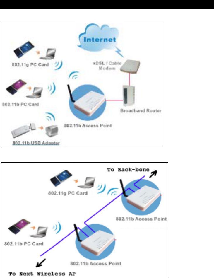
Application
Example 1
Example 2

3
Parts Names and Functions
1. Front Panel: (LED Indicators)
LED Status
Indicator Color Solid Flashing
1 Power Green Turns solid green when
power is applied to this
device.
N/A.
2 Status Red Turns solid red when the
device is booting, after
boot scuessfully, the light
turn off.
Link/Act. Green Turns solid green when
connected and associated
to at least a client station.
Receiving/
Sending data
WEP/WP
A Orange Turns solid orange when
wireless security is
enabled.
N/A
MAC
Ctrl Orange Turns solid orange when
MAC Control is enabled. N/A
3~6
Wireless
WDS Orange Turn solid orange when
WDS is enabled. N/A
7 LAN 1
8 LAN 2
Green
Turns solid green when
linked to a local network.
Receiving/
Sending data
Table 1: LED Indicators
4
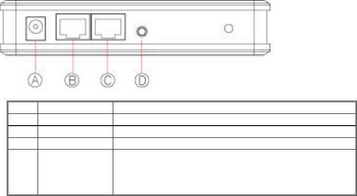
2. Rear Panel: Connection Ports
Port/button Functions
A 12V DC Connects the power adapter plug
B LAN1 Connects to Ethernet
C LAN2 Connects to Ethernet
D
(Factory)
RESET Press over 3 seconds to reboot this device.
Press for over 10 seconds to restore factory settings.
Performing the Factory Reset will erase all previously
entered device settings.
Table 2: Connection Ports

5
Factory Default Settings
Setting Wireless Access Point
Device Name Wireless AP
SSID Default value: 802.11g-AP
Channel 11
WEP Default value: Disabled
IP Address 192.168.100.252
6
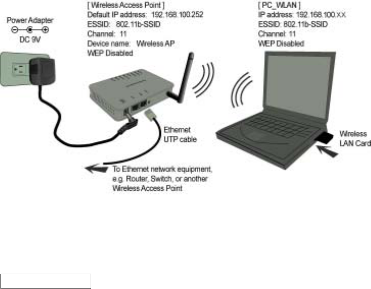
HARDWARE CONNECTION
Note: Before you starting hardware connection, you are advised to find an appropriate
location to place the Access Point. Usually, the best place for the Access Point is at the
center of your wireless network, with line of straight to all your wireless stations. Also,
remember to adjust the antenna; usually the higher the antenna is placed, the better will
be the performance.
1. Connect to your local area network: connect a Ethernet cable to one of the
Ethernet port (LAN1 or LAN2) of this Wireless Access Point, and the other end to a
hub, switch, router, or another wireless access point.
2. Power on the device: connect the included AC power adapter to the Wireless Access
Point’s power port and the other end to a wall outlet.
Check the LEDs:
The Power and LAN # LEDs should be ON. LAN# LED will even blink if there is traffic.
The Link/Act LED will be on in static when associated with a station and blink whenever
this AP receives data packets in the air.
If the Status LED glows after self-test , it means this Wireless Access Point fails on self
test. Please ask your dealer for technical support.
3. Configure your PC: Make sure your local PC(s) has wireless network adapter
installed.
7
ABOUT THE OPERATION MODES
This device provides four operational applications with Access Point, Bridge, Client
(Ad-hoc) and Client (Infrastructure) modes, which are mutually exclusive.
This device is shipped with configuration that is functional right out of the box. If you
want to change the settings in order to perform more advanced configuration or even
change the mode of operation, you can use the web-based utility provided by the
manufacturer as described in the following sections.
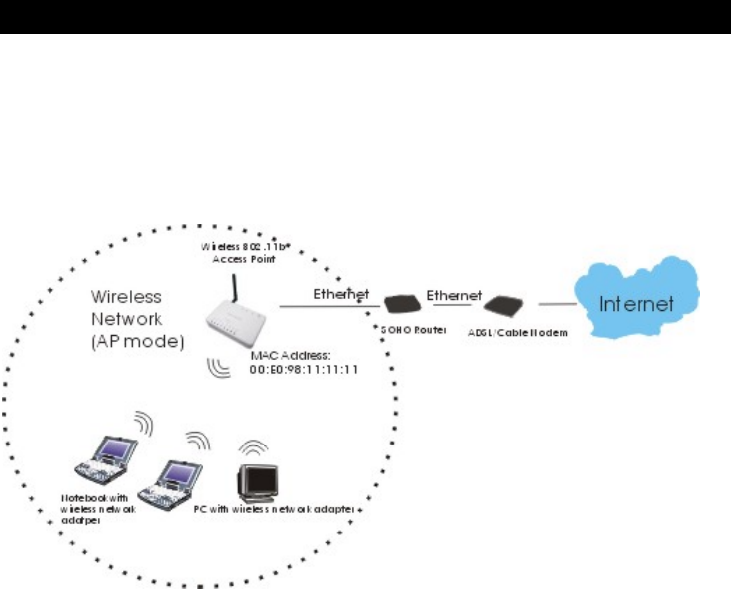
Access Point Mode
When acting as an access point, this device connects all the stations (PC/notebook with
wireless network adapter) to a wired network. All stations can have the Internet access if
only the Access Point has the Internet connection.
See the sample application below.
To set the operation mode to Access Point, please go to “Wireless JBasic Settings”, in
the “Mode” field click the down arrow b to select AP mode.
8
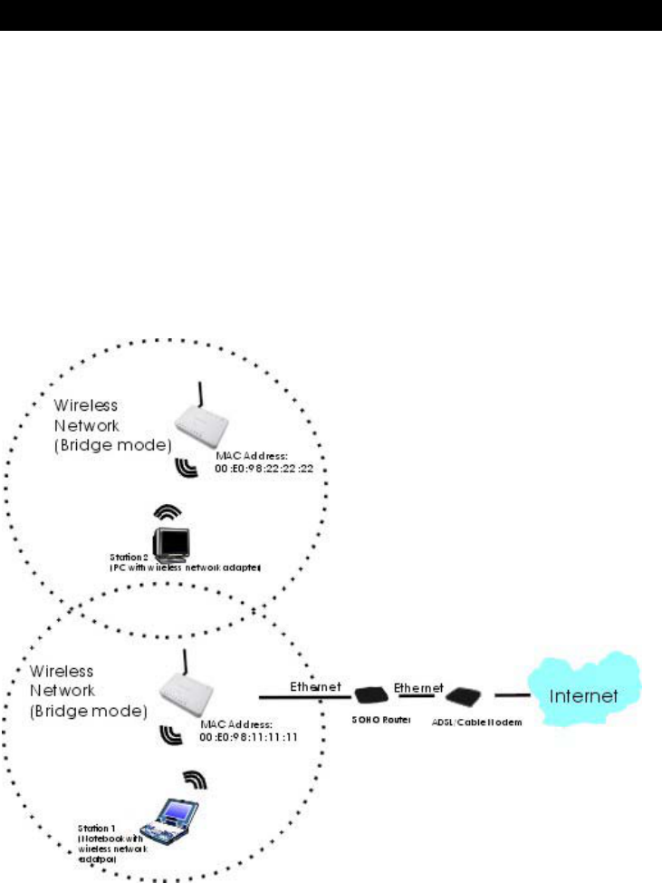
Bridge Mode
Refer to the illustration below. While acting as Bridges, AP1 (with Station 1 being
associated to) and AP2 (with Station 2 being associated) can communicate with each other
through wireless interface (with WDS). Thus Station 1 can communicate with Station 2
and both Station 1 and Station 2 are able to access the Internet if only AP1 or AP2 has the
Internet connection.
To set the operation mode to Bridge, please go to “Wireless JBasic Settings”, in the
“Mode” field click the down arrow b to select AP mode. And go to “Wireless JWDS
Settings” to enable WDS.
Note:
To act as Bridge, both AP1 and AP2 must have WDS enabled and add each other as its
WDS Access Point. (e.g. Add AP2’s MAC address to AP1’s “WDS AP List” and vice
versa)
9
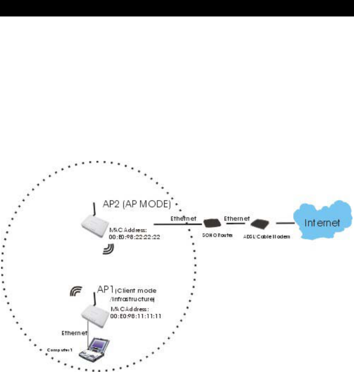
Client Mode (Infrastructure)
If set to Client (Infrastructure) mode, this device can work like a wireless station when it’s
connected to a computer so that the computer can send packets from wired end to wireless
interface.
Refer to the illustration below. This station (AP1 plus the connected computer 1) can
associate to another Access Point (AP2), and then can have the Internet access if the other
Access Point (AP2) has the Internet connection.
To set the operation mode to Client (Infrastructure), please go to “Wireless JBasic
Settings”, in the “Mode” field click the down arrow b to select Client mode, and then
select “Network Type” as “Infrastructure”.
10
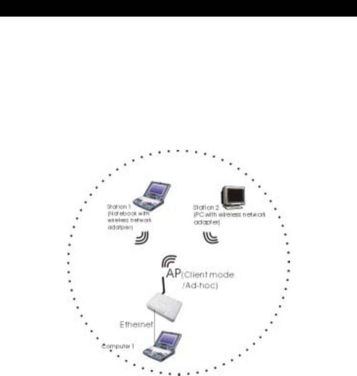
Client Mode (Ad-hoc)
If set to the Client (Ad-hoc) mode, this device can work like a wireless station when it is
connected to a computer so that the computer can send packets from wired end to wireless
interface. You can share files and printers between wireless stations (PC and laptop with
wireless network adapter installed).
See the sample application below.
To set the operation mode to Client (Ad-hoc), please go to “Wireless JBasic Settings”,
in the “Mode” field click the down arrow b to select Client mode, and then select
Network Type as “Ad-hoc”.

11
WDS Bridge Mode (Repeater Mode)
The WDS (Wireless Distributed System) function let this access point acts as a wireless
LAN access point and repeater at the same time. Users can use this feature to build up a
large wireless network in a large space like airports, hotels and schools …etc. This feature
is also useful when users want to bridge networks between buildings where it is
impossible to deploy network cable connections between these buildings.
12
CONFIGURATION
Login
1. Start your computer. Connect an Ethernet cable between your computer and the
Wireless Access Point.
2. Make sure your wired station is set to the same subnet as the Wireless Access Point,
i.e. 192.168.100.12.
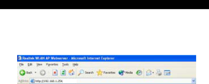
3. Start your WEB browser. In the Address box, enter the following:
HTTP://192.168.1.254
The configuration menu is divided into four categories: Status, Wireless, TCP/IP,
and Other settings. Click on the desired setup item to expand the page in the main
navigation page. The setup pages covered in this utility are described below.
13
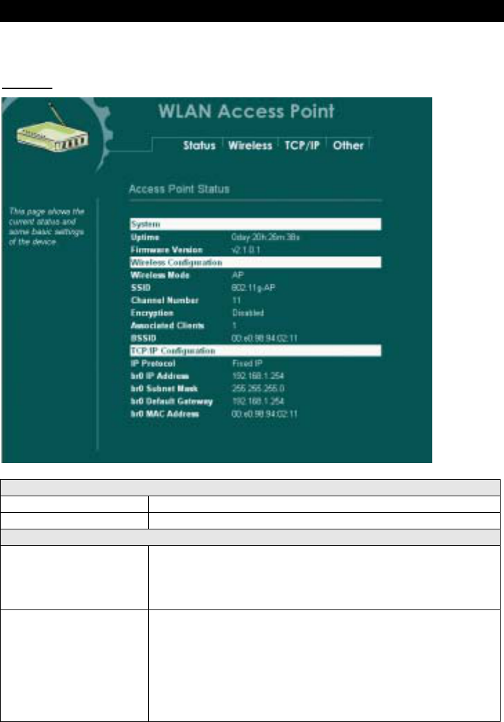
Status
In this screen, you can see the current settings and status of this Access Point. You
can change settings by selecting specific tab described in below.
System
System
Uptime The time period since the device was up.
Firmware Version The current version of the firmware installed in this device.
Wireless Configuration
Wireless Mode There are four modes supported, Access Point, Client (Ad-
hoc and Infrastructure), and Bridge. The default mode is
Access Point. If you want to change to bridge mode, please
go to Wireless/WDS Setting to enable the WDS function.
SSID The SSID differentiates one WLAN from another, therefore,
all access points and all devices attempting to connect to a
specific WLAN must use the same SSID. It is case-sensitive
and must not exceed 32 characters. A device will not be
permitted to join the BSS unless it can provide the unique
SSID. An SSID is also referred to as a network name because
essentially it is a name that identifies a wireless network.

14
Channel Number The number of channels supported depends on the region of
this Access Point. All stations communicating with the Access
Point must use the same channel.
Encryption WEP Encryption (Wired Equivalent Privacy) is set to
Disabled by default. When WEP is enabled, data packet is
encrypted
before being transmitted. The WEP prevents data packets from
being eavesdropped by unrelated people. By using WEP data
encryption, there may be a significant degradation of the data
throughput on the wireless link.
Associated Clients Displays the total number of clients associated to this AP. You
can have up to 64 clients to associate to this Access Point.
BSSID BSSID displays the ID of current BSS, which uniquely
identifies each BSS. In AP mode, this value is the MAC
address of this Access Point.
TCP/IP Configuration
IP Protocol Display the method to get the IP of this AP, which could be
obtained by Fixed-IP or DHCP-client.
br0 IP Address Current IP address for this Access Point
br0 Subnet Mask Current Subnet mask for this Access Point
br0 Default Gateway Default Gateway for this Access Point
br0 MAC Address The MAC Address for this Access Point
System Log
This page display log events with time when events happened, log events’ types, log
sources and the description for events themselves. System manager can use the system log
to trace when problems occur.
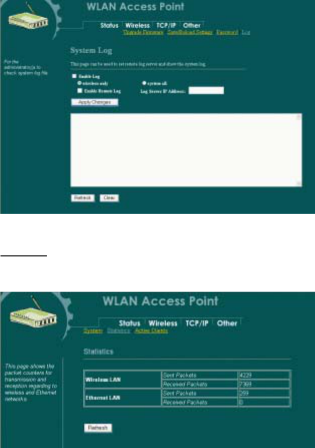
15
Statistics
The Statistics table shows the packets sent/received over wireless and ethernet LAN
respectively.
16
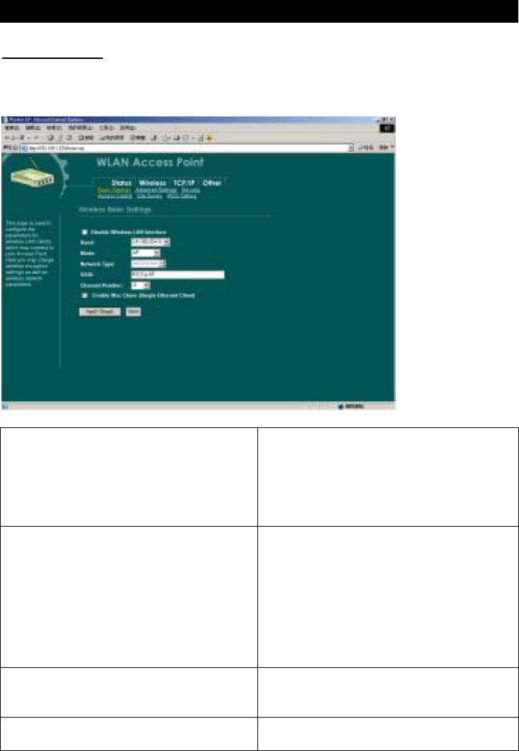
Wireless
Basic Settings
This page includes all primary and major parameters. Any parameter change will cause
the device to reboot for the new settings to take effect.
Disable Wireless LAN Interface Check the box to disable the Wireless LAN
Interface, by so doing, you won’t be able to
make wireless connection with this Access
Point in the network you are located. In
other words, this device will not be visible
by any wireless station.
Band You can choose one mode of the following
you need.
2.4GHz (B): 802.11b supported rate
only.
2.4GHz (G): 802.11g supported rate
only.
2.4GHz (B+G): 802.11b supported rate
and 802.11g supported rate.
The default is 2.4GHz (B+G) mode.
Mode This Wireless Access Point can support four
modes AP, Client, Bridge and Repeater.
(Refer to page 7-11 for detailed information)
Network Type When in Client mode, you can select
between Ad-Hoc and Infrastructure.

17
SSID The SSID differentiates one WLAN from
another, therefore, all access points and all
devices attempting to connect to a specific
WLAN must use the same SSID. It is case-
sensitive and must not exceed 32 characters.
A device will not be permitted to join the
BSS unless it can provide the unique SSID.
An SSID is also referred to as a network
name because essentially it is a name that
identifies a wireless network.
Channel Number Allow user to set the channel manually or
automatically.
If set channel manually, just select the
channel you want to specify.
If “Auto” is selected, user can set the
channel range to have Wireless Access Point
automatically survey and choose the channel
with best situation for communication.
The number of channels supported depends
on the region of this Access Point. All
stations communicating with the Access
Point must use the same channel.
Enable Mac Clone (Sin
g
le Ethernet
Client) If your ISP restricts service to PCs only, use
the MAC Clone feature to copy a PC Media
Access Control (MAC) address to your
router. This procedure will cause the router
to appear
as a single PC, while allowing online access
to multiple computers on your network.
Apply Changes Press to save the new settings on the screen.
Reset Press to discard the data you have entered
since last time you press Apply Change.
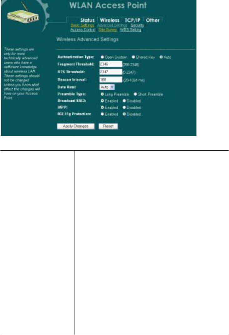
Advanced Settings
It is not recommended that settings in this page to be changed unless advanced users want
to change to meet their wireless environment for optimal performance
18
Authentication Type To provide a certain level of security, the IEEE 802.11
standard has defined two types of authentication methods,
Open System and Shared Key. With Open System
authentication, a wireless PC can join any network and
receive any messages that are not encrypted. With Shared
Key authentication, only those PCs that possess the correct
authentication key can join the network. By default, IEEE
802.11 wireless devices o
p
erate in an Open System network.
Wired Equivalent Privacy (WEP) data encryption is used
when the wireless devices are configured to operate in
Shared Key authentication mode.
If the Access Point is using Open System, then the wireless
adapter will need to be set to the same authentication mode.
Shared Key is used when both the sender and the recipient
share a secret key.
Select Auto for the network adapter to select the
Authentication mode automatically depending on the Access
Point Authentication mode.

19
Fragment Threshold Fragmentation mechanism is used for improving the
efficiency when high traffic flows along in the wireless
network. If your 802.11g Wireless LAN PC Card often
transmit large files in wireless network, you can enter new
Fragment Threshold value to split the packet. The value
can be set from 256 to 2346. The default value is 2346.
RTS Threshold RTS Threshold is a mechanism implemented to prevent the
“Hidden Node” problem. “Hidden Node” is a situation in
which two stations are within range of the same Access
Point, but are not within range of each other. Therefore, they
are hidden nodes for each other. When a station starts data
transmission with the Access Point, it might not notice that
the other station is already using the wireless medium. When
these two stations send data at the same time, they might
collide when arriving simultaneously at the Access Point.
The collision will most certainly result in a loss of messages
for both stations.
Thus, the RTS Threshold mechanism provides a solution to
p
revent data collisions. When you enable RTS Threshold on
a suspect “hidden station”, this station and its Access Point
will use a Request to Send (RTS). The station will send an
RTS to the Access Point, informing that it is going to
transmit the data. Upon receipt, the Access Point will
respond with a CTS message to all station within its range to
notify all other stations to defer transmission. It will also
confirm the requestor station that the Access Point has
reserved it for the time-frame of the requested transmission.
If the “Hidden Node” problem is an issue, please specify the
packet size. The RTS mechanism will be activated if the data
size exceeds the value you set.. The default value is 2347.
Warning: Enabling RTS Threshold will cause redundant
network overhead that could negatively affect the
throughput performance instead of providing a remedy.
This value should remain at its default setting of 2347. Should you
encounter inconsistent data flow, only minor modifications of this
value are recommended.
Beacon Interval Beacon Interval is the amount of time between beacon
transmissions. Before a station enters power save mode, the
station needs the beacon interval to know when to wake up
to receive the beacon (and learn whether there are buffered
frames at the access point).
Data Rate By default, the unit adaptively selects the highest
p
ossible
rate for transmission. Select the basic rates to be used among

20
the following options: Auto, 1, 2, 5.5, 11or 54 Mbps. For
most networks the default setting is Auto which is the best
choice. When Auto is enabled the transmission rate will
select the optimal rate. If obstacles or interference are
p
resent, the system will automatically fall back to a lower
rate.
Preamble Type A preamble is a signal used in wireless environment to
synchronize the transmitting timing including
Synchronization and Start frame delimiter. In a "noisy"
network environment, the Preamble Type should be set to
Long Preamble. The Short Preamble is intended for
applications where minimum overhead and maximum
p
erformance is desired. If in a "noisy" network environment,
the performance will be decreased.
Broadcast SSID Select enabled to allow all the wireless stations to detect the
SSID of this Access Point.
IAPP IAPP (Inter Access Point Protocol) is designed for the
enforcement of unique association throughout a ESS
(Extended Service Set) and a secure exchange of station’s
security context between current access point (AP) and new
AP during handoff period.
802.11g Protection The 802.11g standard includes a protection mechanism to ensure
mixed 802.11b and 802.11g operation. If there is no such kind of
mechanism exists, the two kinds of standards may mutually
interfere and decrease network’s performance.
Apply Change Press to save the new settings on the screen.
Reset Press to discard the data you have entered since last time
you press Apply Change.
21
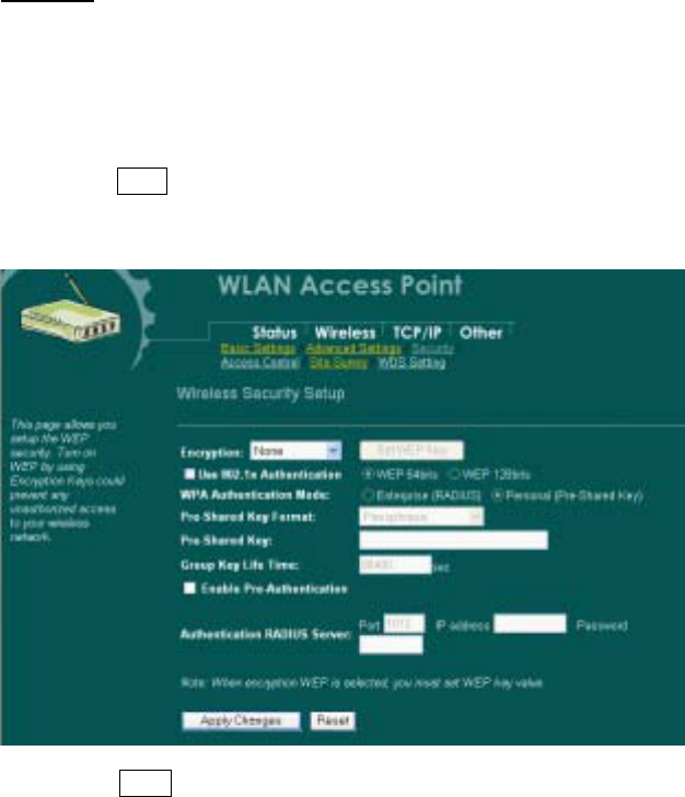
Security
Here you can configure the security of your wireless network. Selecting different method
will enable you to have different level of security. Please note that by using any
encryption, by which data packet is encrypted before transmission to prevent data packets
from being eavesdropped by unrelated people, there may be a significant degradation of
the data throughput on the wireless link.
Encryption : None ( Encryption is set to None by default. )
If Use 802.1x Authentication is selected, the RADIUS Server will proceed to check the
802.1x Authentication.
Encryption: WEP
If WEP is selected, users will have to Set WEP keys either manually, or select to Use
802.1x Authentication to make the RADIUS server to issue the WEP key dynamically.
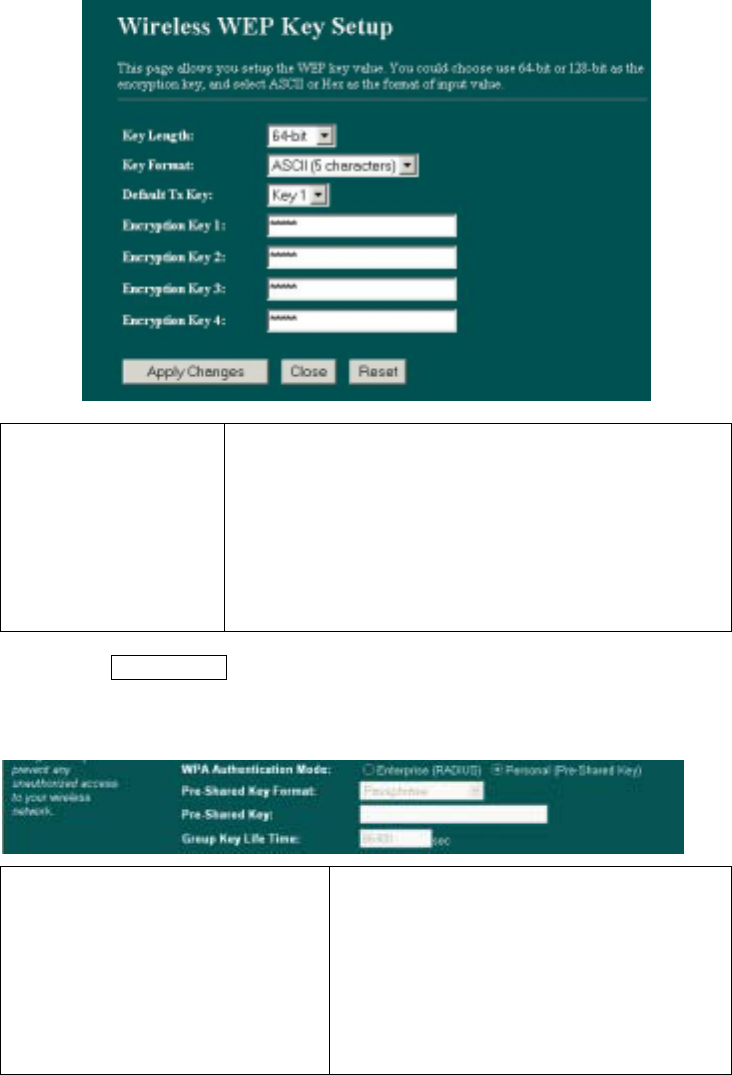
22
Set WEP key Click the Set WEP Keys will prompt you a
window to set 64bit or 128bit Encryption.
Select HEX if you are using hexadecimal
numbers (0-9, or A-F). Select ASCII if you are
using ASCII characters (case-sensitive).
Ten hexadecimal digits or five ASCII
characters are needed if 64-bit WEP is used;
26 hexadecimal digits or 13 ASCII characters
are needed if 128-bit WEP is used.
Encryption: WPA (TKIP)
WPA (TKIP): If WPA is selected, users will have to select the Authentication modes
between Enterprise (RADIUS) and Personal (Pre-shared Key).
Pre-shared Key Pre-Shared-Key serves as a password. Users
may key in a 1 to 63 characters string to set the
p
assword or leave it blank, in which the 802.1x
Authentication will be activated. Make sure the
same password is used on client's end.
There are two formats for choice to set the Pre-
shared key, i.e. Passphrase and Hex. If Hex is
selected, users will have to enter a 64 characters
strin
g
. For easier confi
g
uration, the Pass
p
hrase

23
(at least 8 characters) format is recommended.
Group Key Life Time Enter the number of seconds that will elapse
before the group key change automatically. The
default is 86400 seconds.
Enable Pre-Authentication The two most important features beyond WPA to
b
ecome standardized through 802.11i/WPA2 are:
pre-authentication, which enables secure fast
roaming without noticeable signal latency.
Preauthentication provides a way to establish a
PMK security association before a client
associates. The advantage is that the client
reduces the time that it's disconnected to the
network.
Authentication RADIUS Server Port: Enter the RADIUS Server’s port number
provided by your ISP. The default is 1812.
IP Address: Enter the RADIUS Server’s IP
Address provided by your ISP.
Password: Enter the password that the AP
shares with the RADIUS Server.
Apply Change Press to save the new settings on the screen.
Reset Press to discard the data you have entered since last time you
press Apply Change.
Access Control
When Enable Wireless Access Control is checked, only those clients whose wireless
MAC addresses listed in the access control list can access this Access Point. If the list
contains no entries with this function being enabled, then no clients will be able to access
this Access Point.
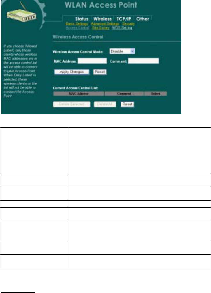
24
Wireless Access Control
Mode Select the Access Control Mode from the pull-down menu.
Disable: Select to disable Wireless Access Control Mode.
Allow Listed: Only the stations shown in the table can
associate with the AP.
Deny Listed: Stations shown in the table won’t be able to
associate with the AP.
MAC Address Enter the MAC Address of a station that is allowed to access
this Access Point.
Comment You may enter up to 20 characters as a remark to the
previous MAC Address.
Apply Changes Press to save the new settings on the screen.
Reset Press to discard the data you have entered since last time
you press Apply Change.
Delete Selected To delete clients from access to this Access Point, you may
firstly check the Select checkbox next to the MAC address
and Comments, and press Delete Selected.
Delete All To delete all the clients from access to this Access Point,
just press Delete All without selecting the checkbox.
Reset If you have made any selection, press Reset will clear all the
select mark.
Site Survey
Site survey displays all the active Access Points and IBSS in the neighborhood. When you
are in the client mode, you can select one AP to associate.
25
Press Refresh to get the latest information.
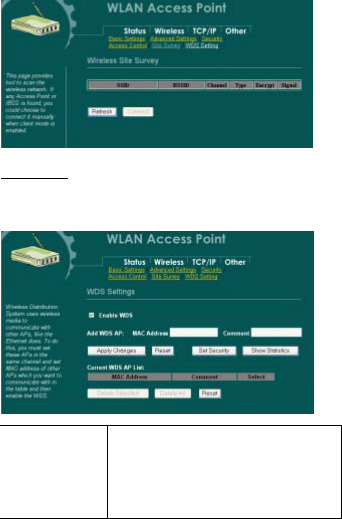
WDS Setting
To enable WDS function will let this AP enter “Bridge Mode”. Two APs in bridge modes
can communicate with each other through wireless interface. That is, two stations
associated to different AP in bridge mode can communicate with each other.
Enable WDS Check the checkbox to enable WDS, all of the WDS
settings in this screen can be enabled only when WDS or
AP+WDS is selected in Wireless Basic Settings screen
(See pageXX).
Add WDS AP
MAC Address: Enter the MAC Address for the Access
Point to establishWDS
Comment: You may enter up to 20 characters as a
remark to the previous MAC Address.
26
Apply Changes Press to save the new settings on the screen.
Reset Press to discard the data you have entered since last time
you press Apply Change.
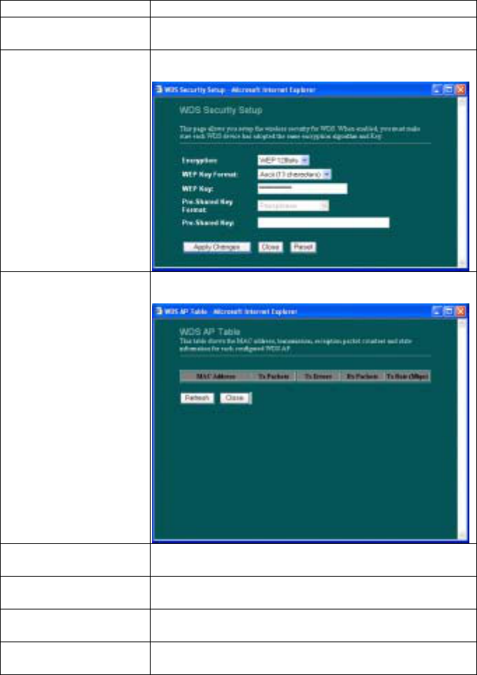
Set Security Click to set the WDS security, please refer to the
previous Wireless Security Setup section (Page XX).
Show Statistics Click to show the detailed information for each WDS
AP.
Current WDS AP List The added Access Points for participating WDS with this
Access Point are shown.
Delete Selected You can delete the WDS Access Points listed above by
marking the checkbox.
Delete All You can delete all of the WDS Access Points listed
above.
Reset Press to discard the data you have entered since last time
you press Apply Change.
27
TCP/IP
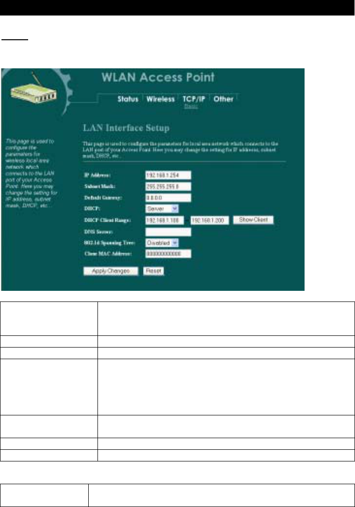
Basic
In this page, you can change the TCP/IP settings of this Access Point, select to
enable/disable the DHCP Client, 802.1d Spanning Tree, and Clone MAC Address.
IP Address This field can be modified only when DHCP Client is disabled.
If your system manager assigned you static IP settings, then you
will have to enter the information provided.
Subnet Mask Enter the information provided by your system manager.
Default Gateway Enter the information provided by your system manager.
DHCP Select Disable, Client or Server from the pull-down menu.
Disable: Select to disable DHCP server function.
Client: Select to automatically get the LAN port IP address from
ISP (For ADSL/Cable Modem).
Server: Select to enable DHCP server function.
DHCP Client
Range 253 IP addresses continuing from 192.168.1.1 to
192.168.1.253
Show Client Click to show Active DHCP Client table.
DNS Server Enter the Domain Name Service IP address.
802.1d
Spanning Tree To enable 802.1d Spanning Tree will prevent the network
from infinite loops. Infinite loop will happen in the network
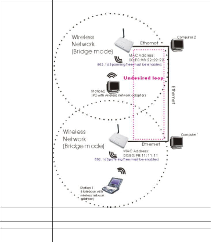
28
when WDS is enabled and there are multiple active paths
between stations.
Clone MAC
Address You can specify the MAC address of your Access Point to
replace the factory setting.
Apply Change Press to save the new settings on the screen.
Reset Press to discard the data you have entered since last time you press
Apply Change.
29
Other
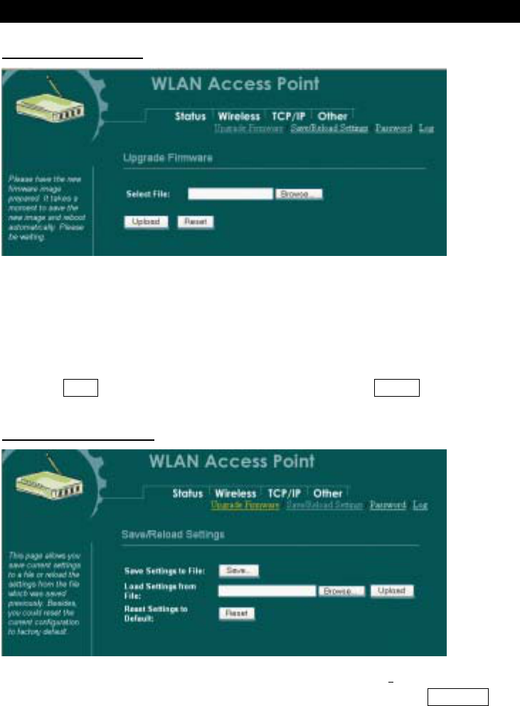
Upgrade Firmware
1. Download the latest firmware from your distributor and save the file on the hard
drive.
2. Start the browser, open the configuration page, click on Other, and click
Upgrade Firmware to enter the Upgrade Firmware window. Enter the new
firmware’s path and file name (i.e. C:\FIRMWARE\firmware.bin). Or, click the
Browse button, find and open the firmware file (the browser will display to
correct file path).
3. Click Reset to clear all the settings on this page. Or click Upload to start the
upgrade.
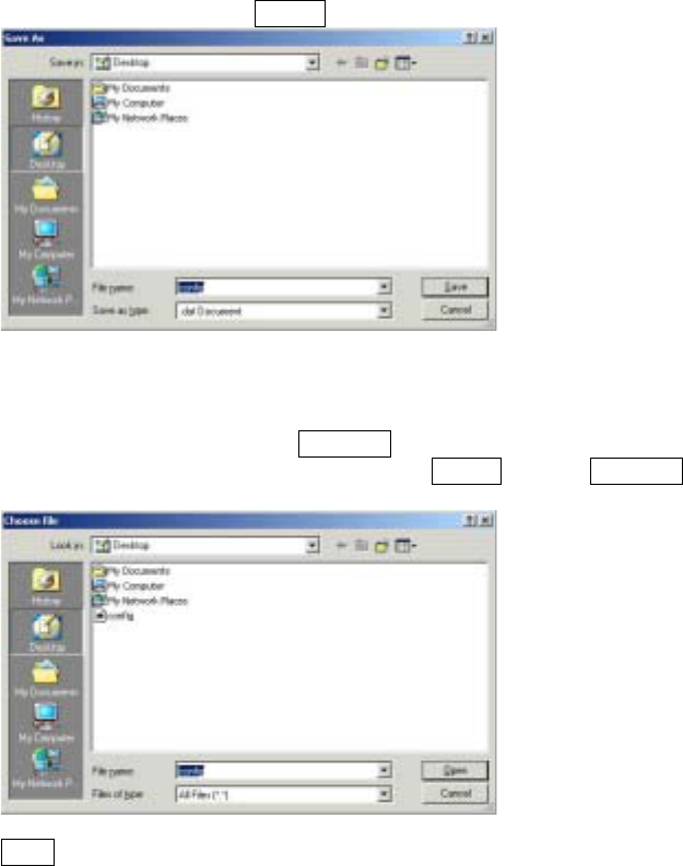
Save/Reload Settings
This function enables users to save the current configurations as a file (i.e.
config.dat) To load configuration from a file, enter the file name or click Browse…
to find the file from your computer.
30
Save Settings to File: Click SAVE.. to save the current configuration to file.
When prompted the upper left screen, select “Save this file to disk”, and the upper
right screen will prompt you a dialog box to enter the file name and the file location.
Load Settings From File: Click Browse… if you want to load a pre-saved file, enter the
file name with the correct path and then click on Upload. Or click Browse… to select the
file.
Reset: Click to restore the default configuration.
31
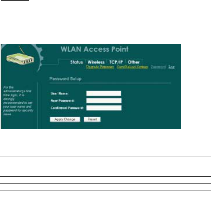
Password
For secure reason, it is recommended that you set the account to access the web server of
this Access Point. Leaving the user name and password blank will disable the protection.
The login screen prompts immediately once you finish setting the account and password.
Remember your user name and password for you will be asked to enter them every time
you access the web server of this Access Point.
User Name Enter your new user name to access the web server. User
name can be up to 30 characters long. User name can contain
letter, number and space. It is case sensitive.
New Password Set your new password. Password can be up to 30 characters
long. Password can contain letter, number and space. It is case
sensitive.
Confirm Password Re-enter the new password for confirmation.
Apply Change Press to save the new settings on the screen.
Reset Press to discard the data you have entered since last time you
press Apply Change.