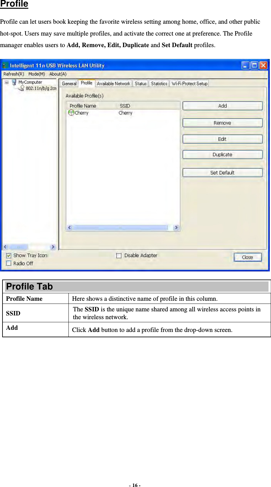
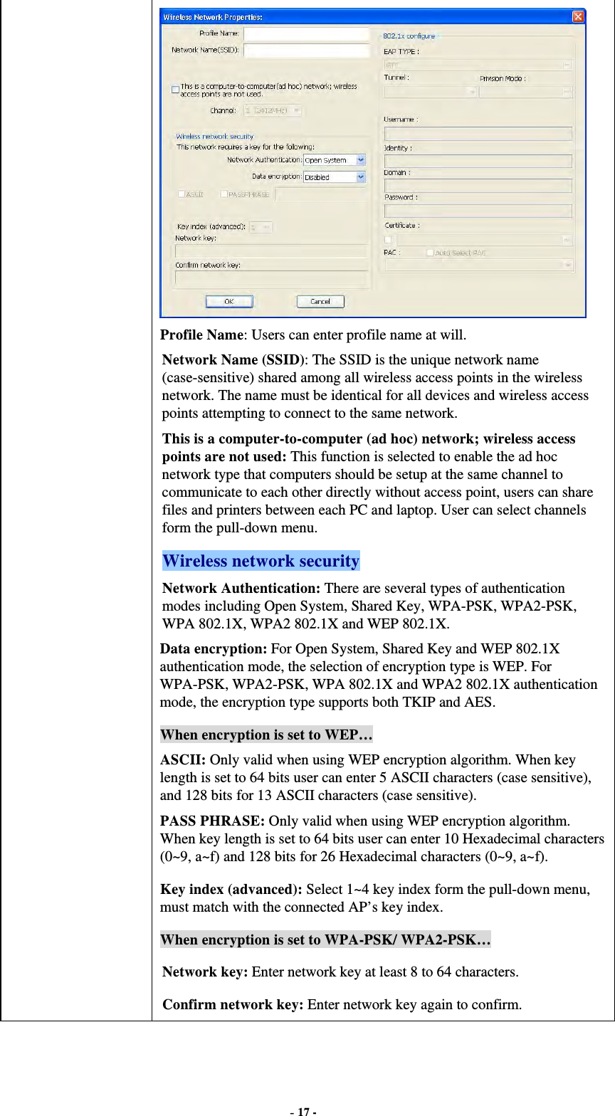
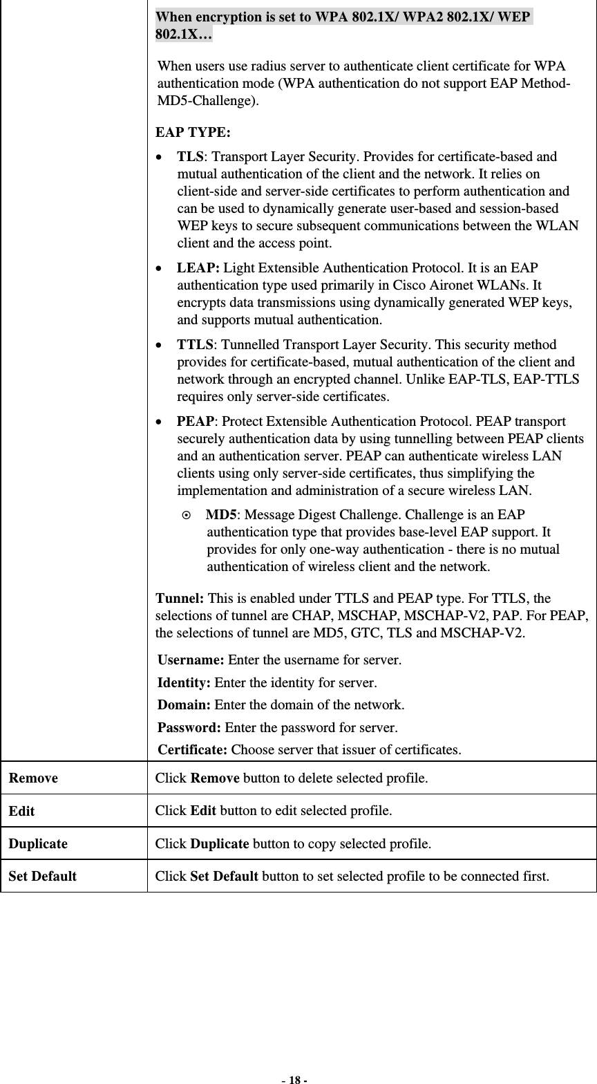
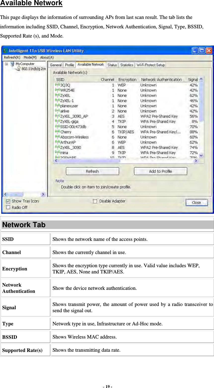
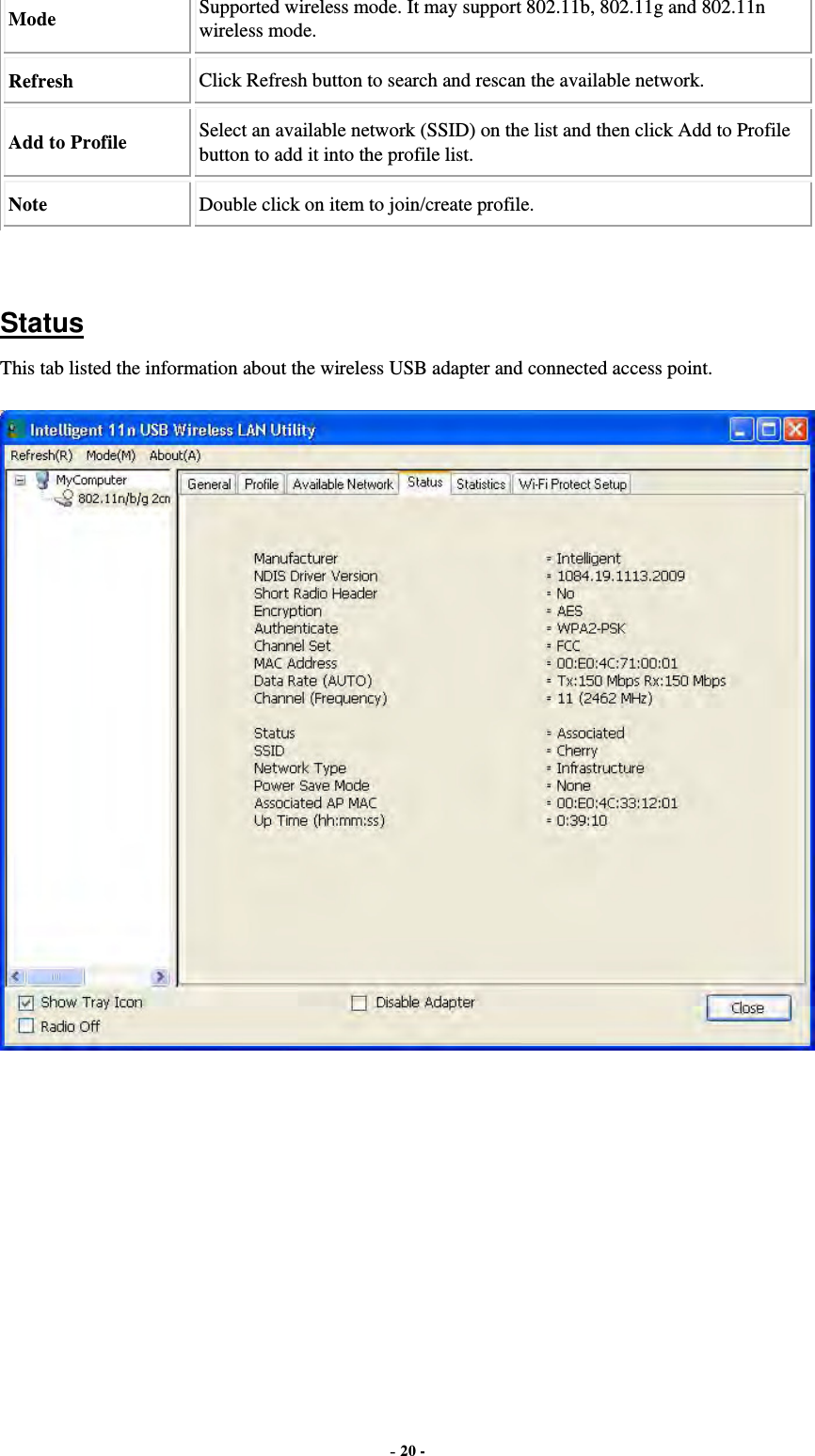
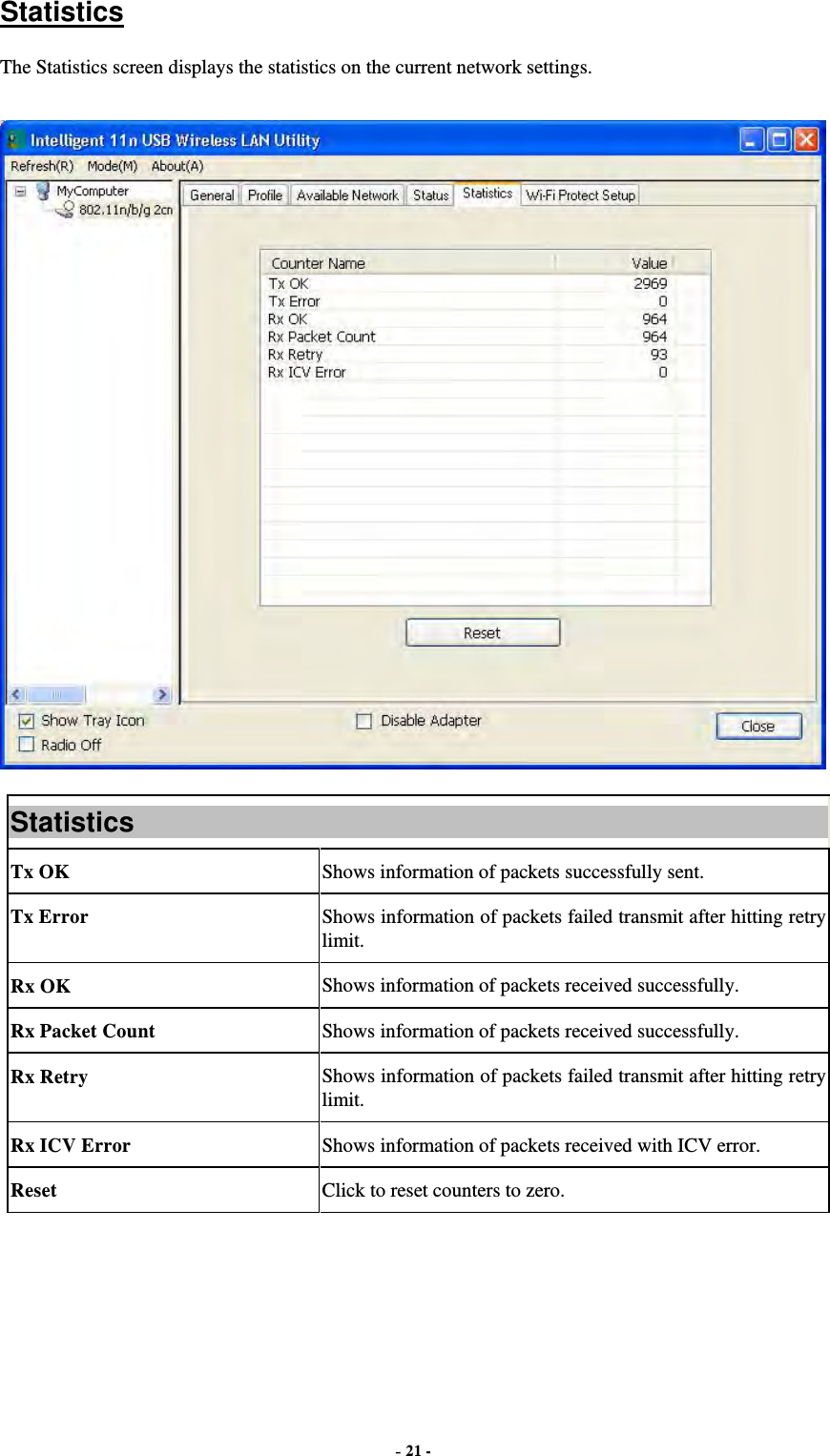
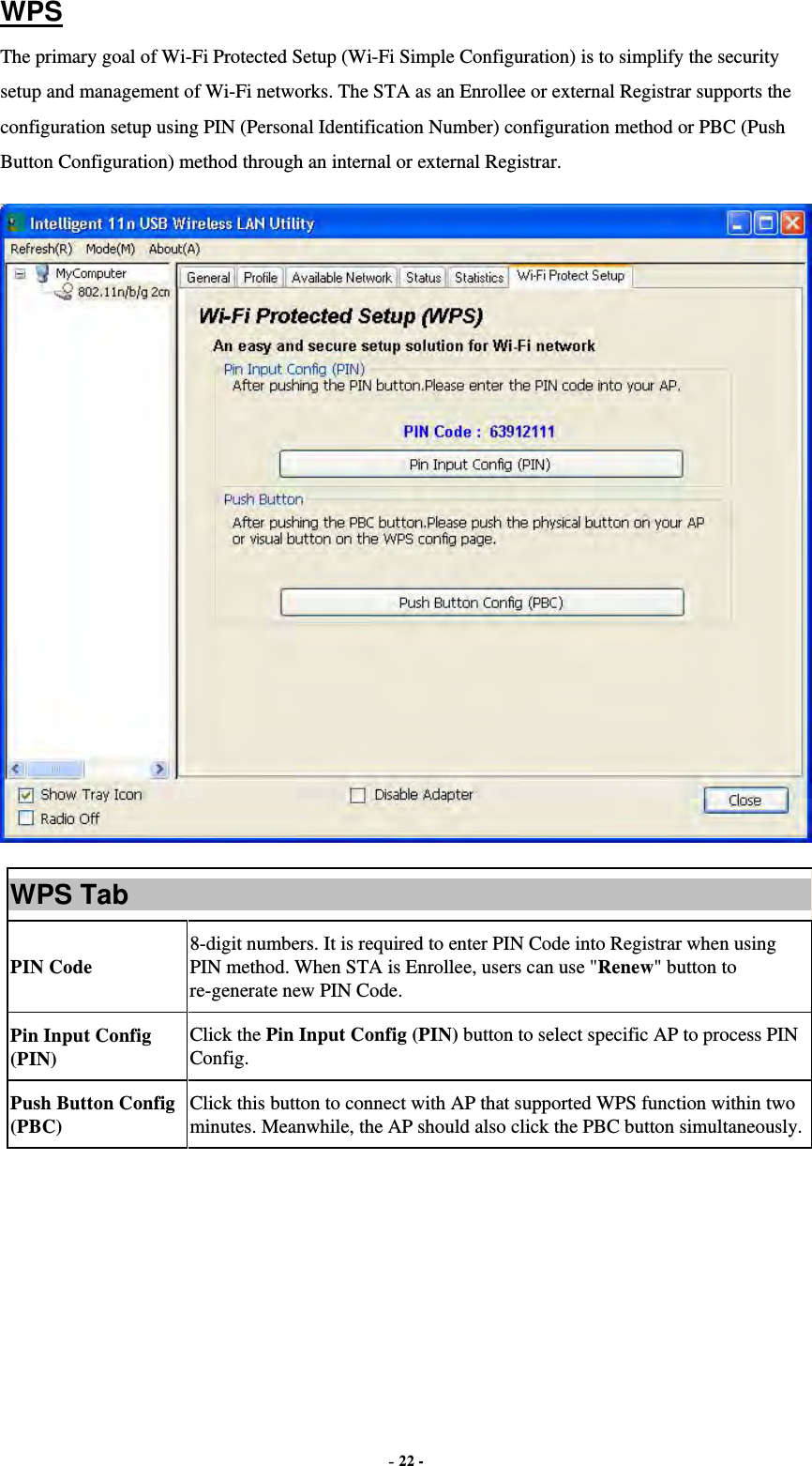
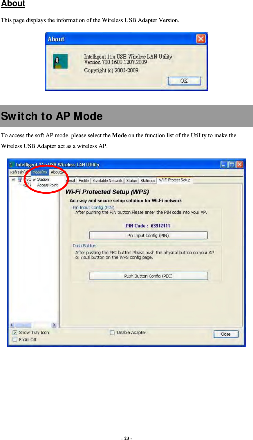
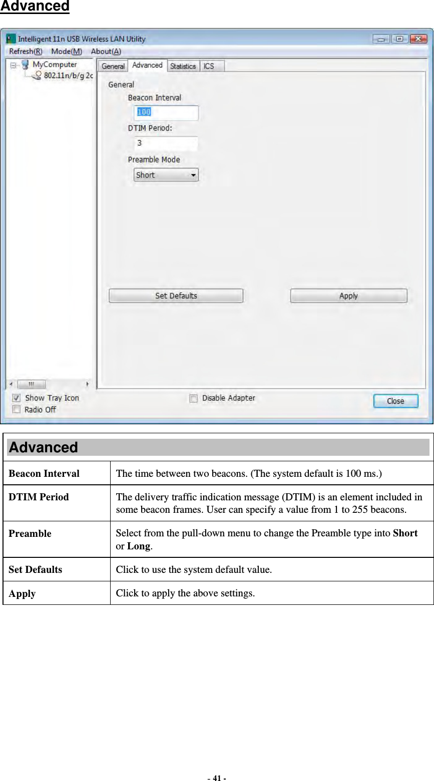
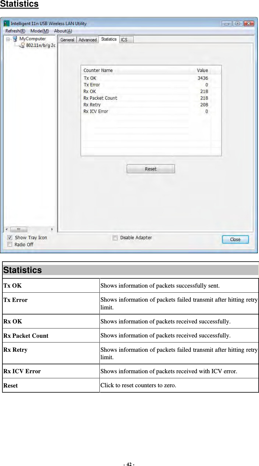
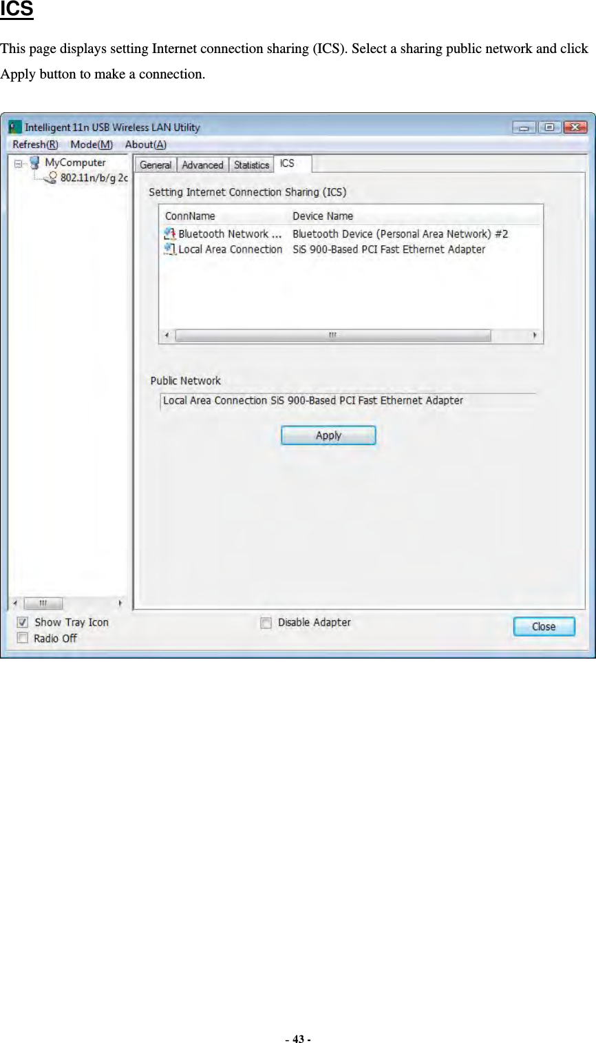
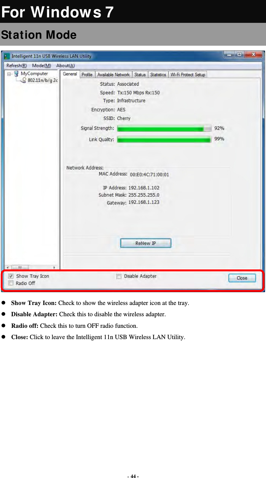
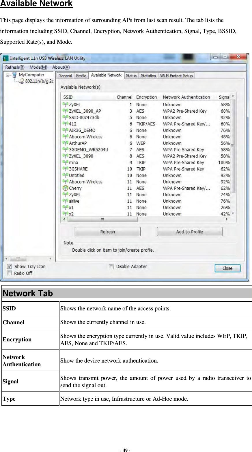
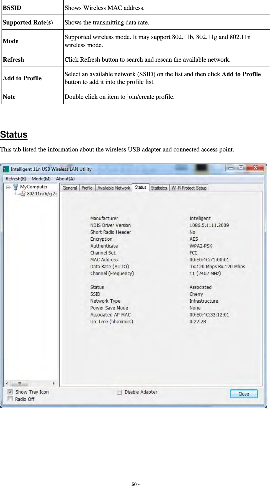
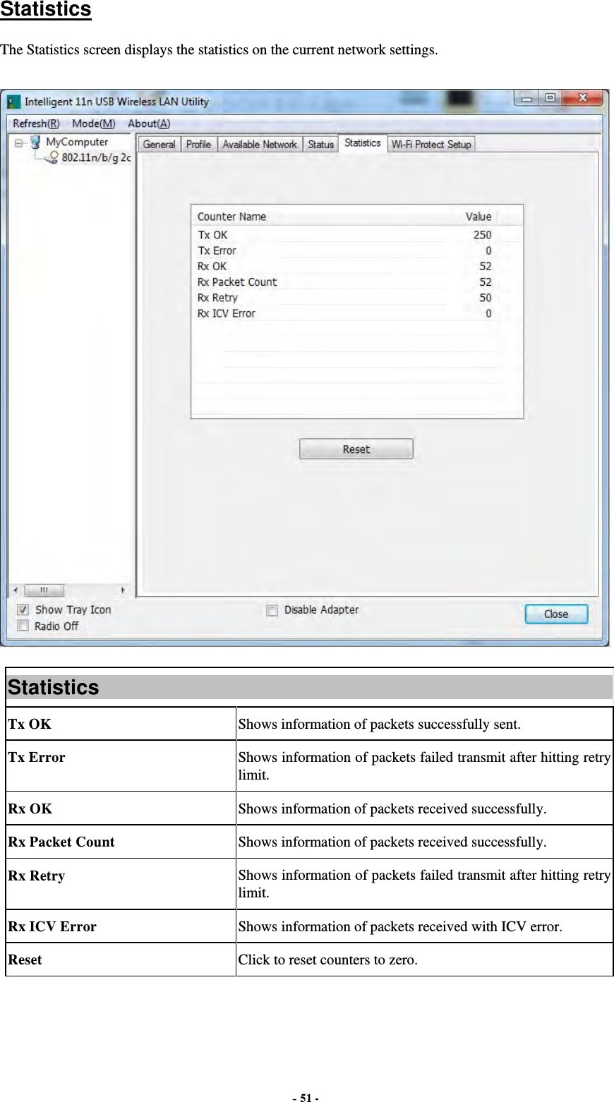
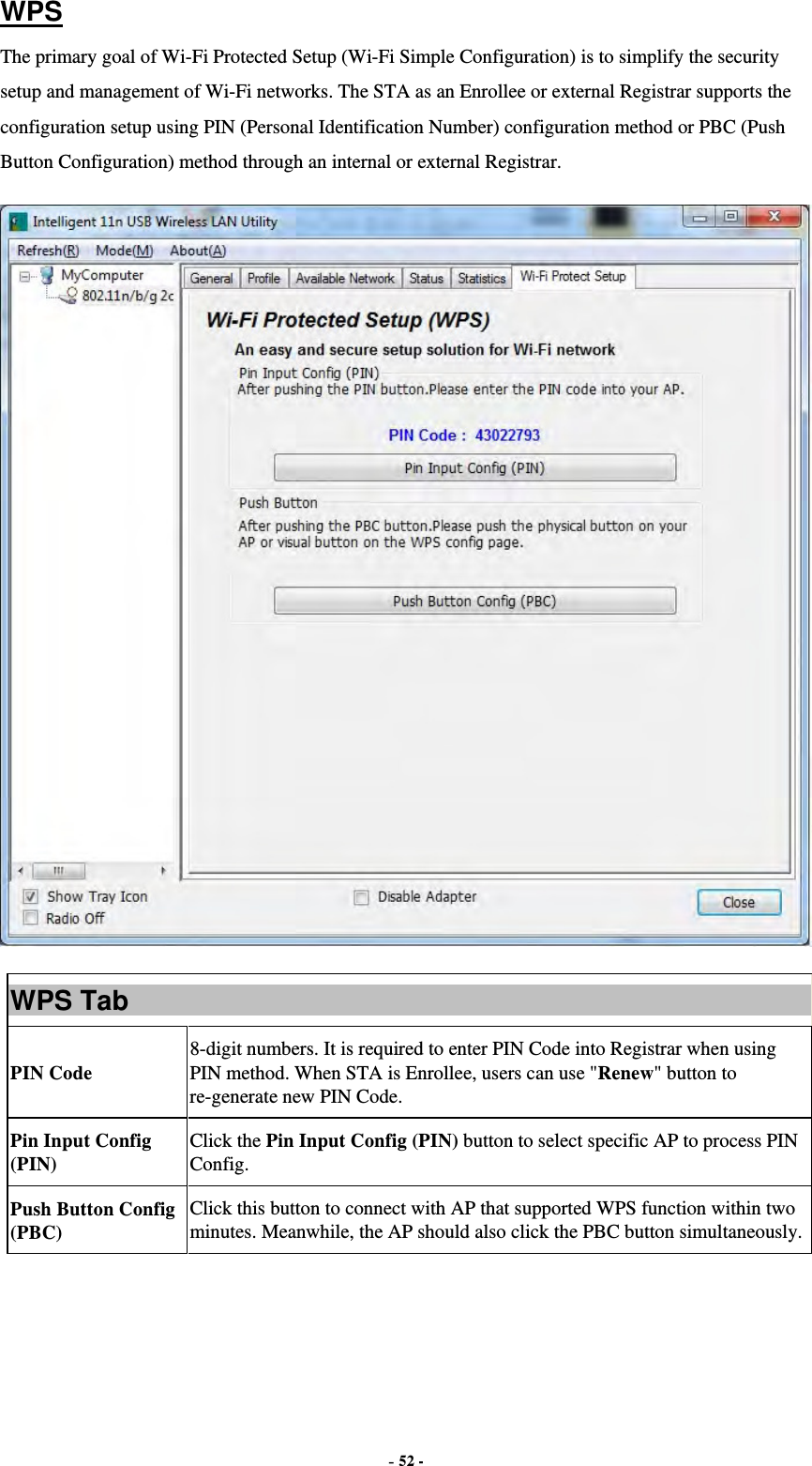
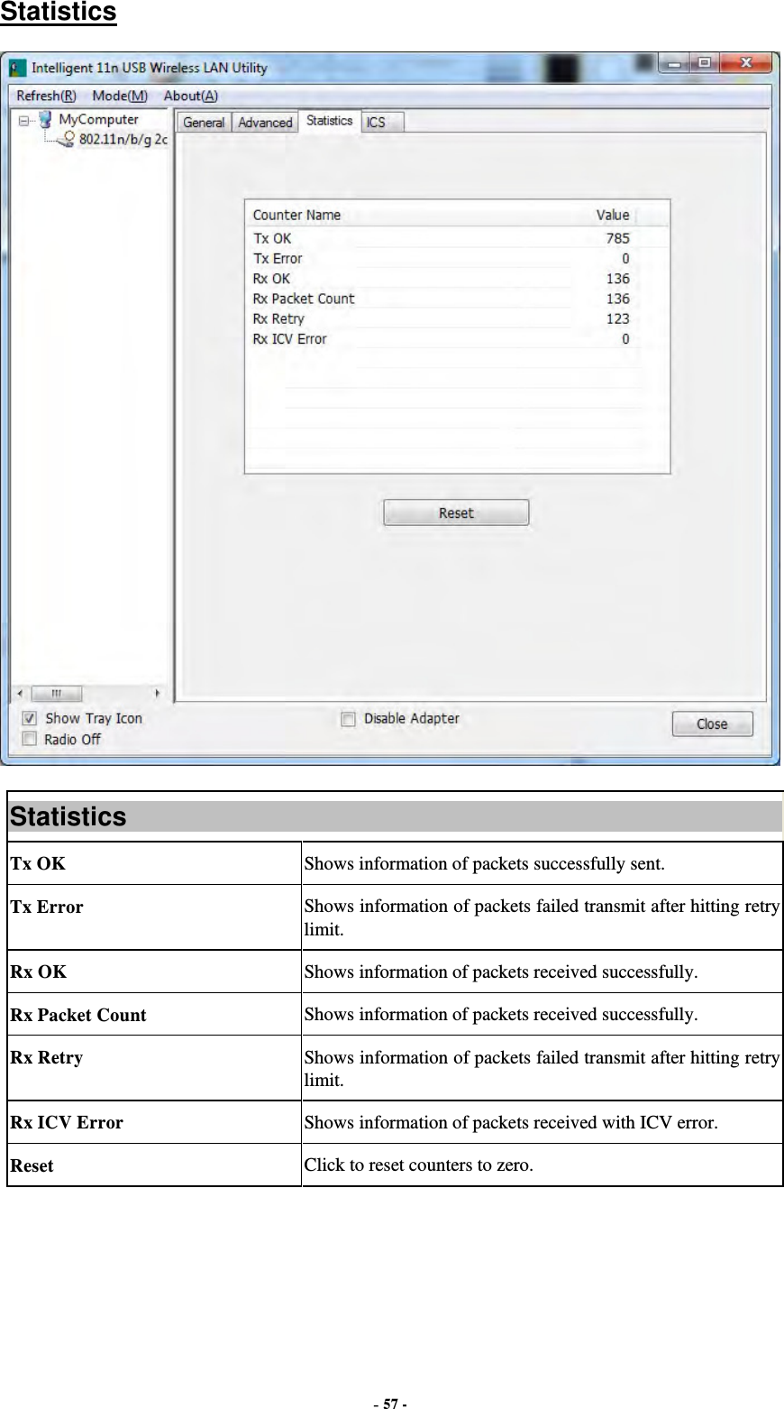
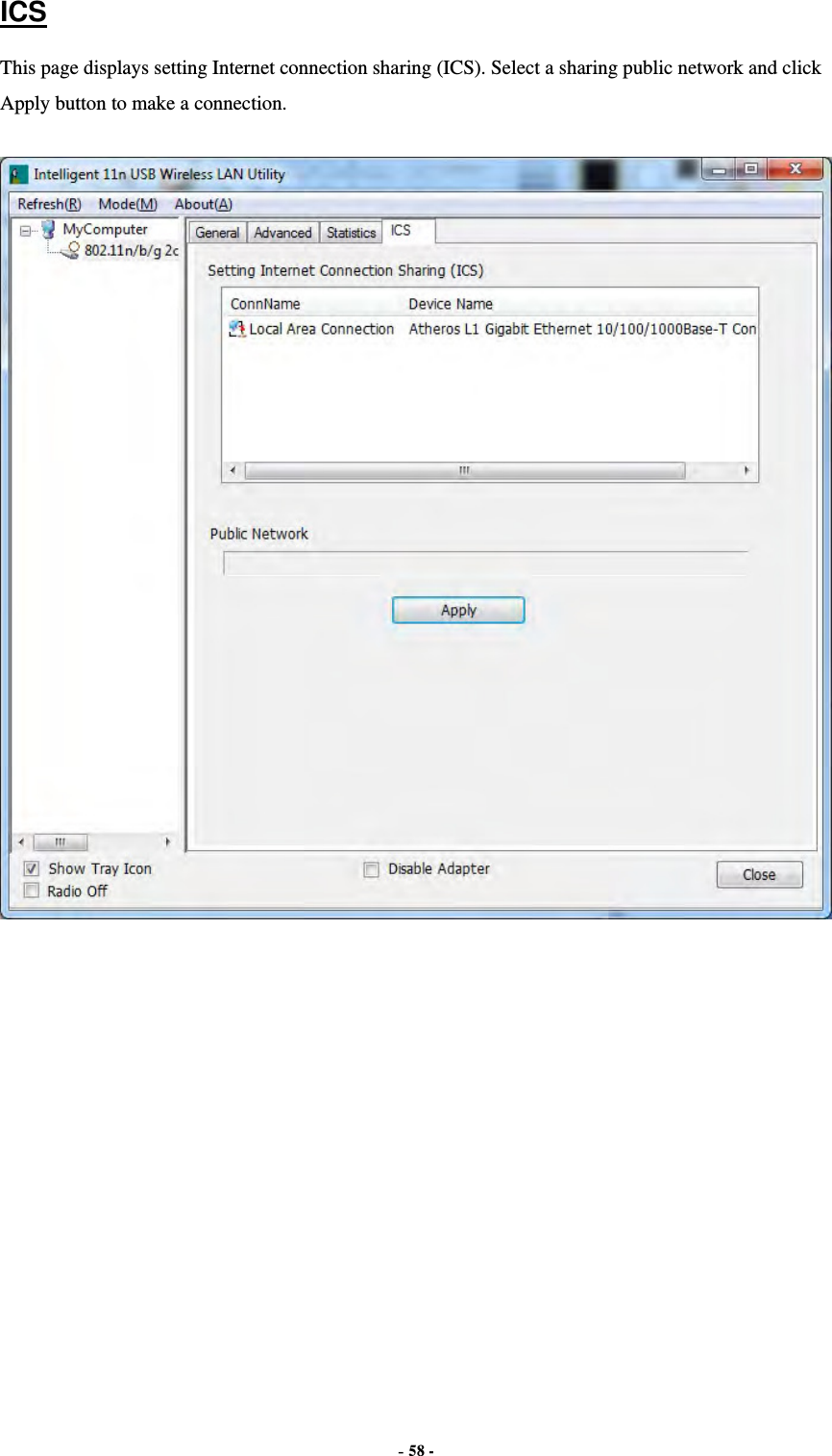
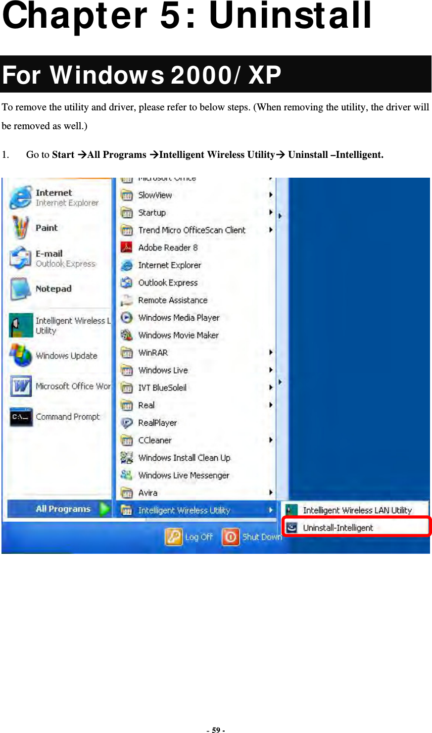
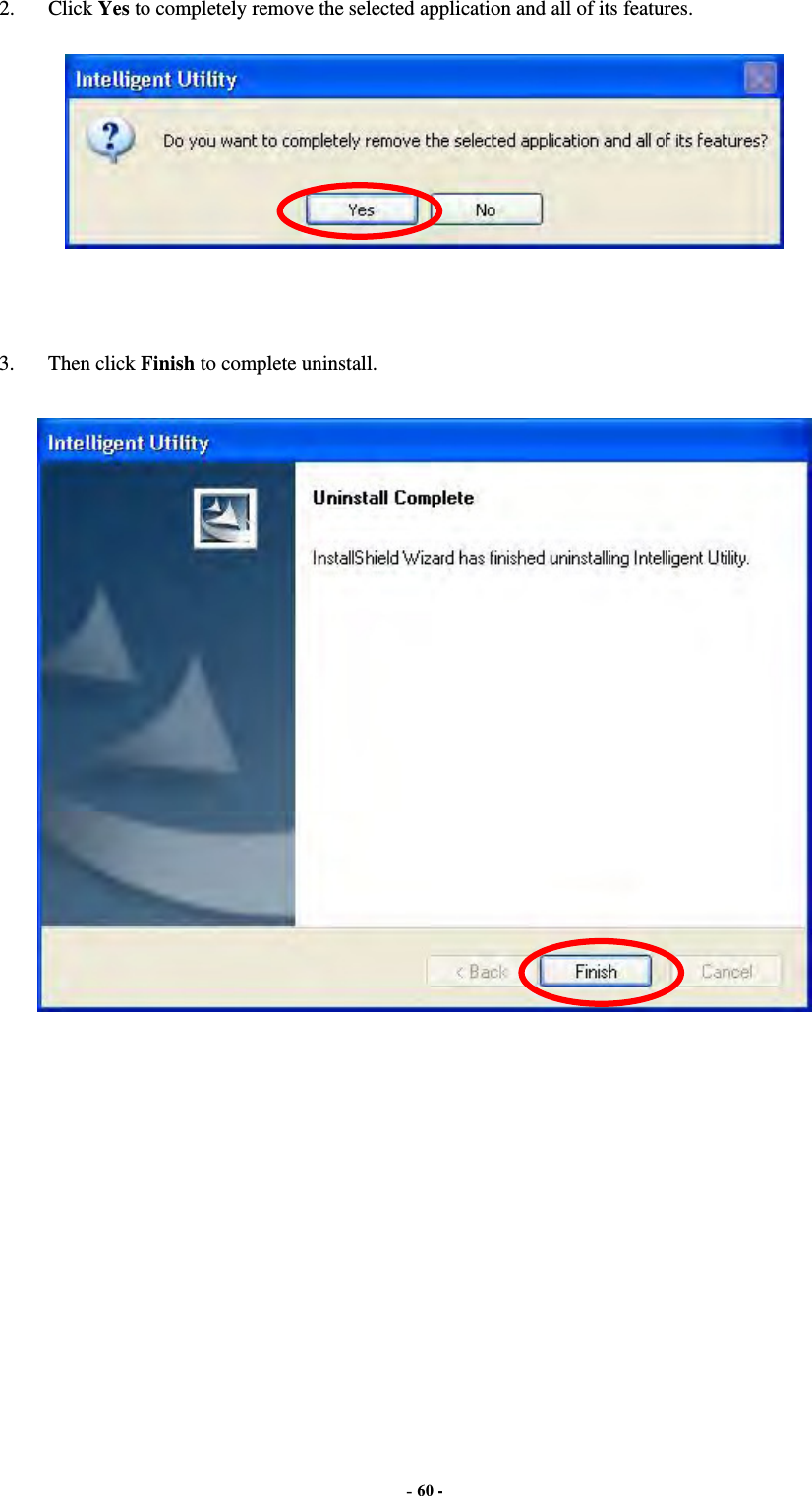
Abocom Systems WM5208 802.11b/g/n Module User Manual

Abocom Systems Inc 802.11b/g/n Module

User Manual

      802.11n/ b/ g WLAN Module WM5208   User’s Manual
  FCC Certification Federal Communication Commission Interference Statement   This equipment has been tested and found to comply with the limits for a Class B digital device, pursuant to Part 15 of the FCC Rules. These limits are designed to provide reasonable protection against harmful interference in a residential installation. This equipment generates, uses and can radiate radio frequency energy and, if not installed and used in accordance with the instructions, may cause harmful interference to radio communications. However, there is no guarantee that interference will not occur in a particular installation. If this equipment does cause harmful interference to radio or television reception, which can be determined by turning the equipment off and on, the user is encouraged to try to correct the interference by one of the following measures: ●  Reorient or relocate the receiving antenna. ●  Increase the separation between the equipment and receiver. ●  Connect the equipment into an outlet on a circuit different from that to which the receiver is connected. ●  Consult the dealer or an experienced radio/TV technician for help.  Warning: Changes or modifications to this unit not expressly approved by the party responsible for compliance could void the user authority to operate the equipment.  CAUT ION This device complies with Part 15 of the FCC Rules. Operation is subject to the following two conditions: (1) This device may not cause harmful interference, and (2) this device must accept any interference received, including interference that may cause undesired operation. For product available in the USA/Canada market, only channel 1~11 can be operated. Selection of other channels is not possible.  This device and its antenna(s) must not be co-located with any other transmitters except in accordance with FCC multi-transmitter product procedures. Refering to the multi-transmitter policy, multiple-transmitter(s) and module(s) can be operated simultaneously without C2P.
 IMPORTANT NOTE: This module is intended for OEM integrator. The OEM integrator is responsible for the compliance to all the rules that apply to the product into which this certified RF module is integrated. Additional testing and certification may be necessary when multiple modules are used.   20cm minimum distance has to be able to be maintained between the antenna and the users for the host this module is integrated into. Under such configuration, the FCC radiation exposure limits set forth for an population/uncontrolled environment can be satisfied.     Any changes or modifications not expressly approved by the manufacturer could void the user's authority to operate this equipment.   USERS MANUAL OF THE END PRODUCT: In the users manual of the end product, the end user has to be informed to keep at least 20cm separation with the antenna while this end product is installed and operated. The end user has to be informed that the FCC radio-frequency exposure guidelines for an uncontrolled environment can be satisfied. The end user has to also be informed that any changes or modifications not expressly approved by the manufacturer could void the user's authority to operate this equipment. If the size of the end product is smaller than 8x10cm, then additional FCC part 15.19 statement is required to be available in the users manual: This device complies with Part 15 of FCC rules. Operation is subject to the following two conditions: (1) this device may not cause harmful interference and (2) this device must accept any interference received, including interference that may cause undesired operation.   LABEL OF THE END PRODUCT: The final end product must be labeled in a visible area with the following " Contains TX FCC ID: MQ4WM5208 ". If the size of the end product is larger than 8x10cm, then the following FCC part 15.19 statement has to also be available on the label:  This device complies with Part 15 of FCC rules. Operation is subject to the following two conditions: (1) this device may not cause harmful interference and (2) this device must accept any interference received, including interference that may cause undesired operation.    IC C󲘒rti󲘓icati󲘜󲘛 This device complies with Industry Canada license-exempt RSS standard(s). Operation is subject to the following two conditions: (1) this device may not cause interference, and (2) this device must accept any interference, including interference that may cause undesired operation of the device. Le présent appareil est conforme aux CNR d'Industrie Canada applicables aux appareils radio exempts de licence. L'exploitation est autorisée aux deux conditions suivantes : (1) l'appareil ne doit pas produire de brouillage, et (2) l'utilisateur de l'appareil doit accepter tout brouillage radioélectrique subi, même si le brouillage est susceptible d'en compromettre le fonctionnement.   For product available in the USA/Canada market, only channel 1~11 can be operated. Selection of other channels is not possible. Pour les produits disponibles aux États-Unis / Canada du marché, seul le canal 1 à 11 peuvent être exploités. Sélection d'autres canaux n'est pas possible.   This device and its antenna(s) must not be co-located with any other transmitters except in accordance with IC multi-transmitter product procedures. Refering to the multi-transmitter policy, multiple-transmitter(s) and module(s) can be operated simultaneously without reassessment permissive change. Cet appareil et son antenne (s) ne doit pas être co-localisés ou fonctionnement en association avec une autre antenne ou transmetteur.
 IMPORTANT NOTE: IC Radiation Exposure Statement: This equipment complies with IC RSS-102 radiation exposure limits set forth for an uncontrolled environment. This equipment should be installed and operated with minimum distance 20 cm between the radiator & your body. Cet équipement est conforme aux limites d'exposition aux rayonnements IC établies pour un environnement non contrôlé. Cet équipement doit être installé et utilisé avec un minimum de 20 cm de distance entre la source de rayonnement et votre corps.   This module is intended for OEM integrator. The OEM integrator is still responsible for the IC compliance requirement of the end product, which integrates this module.  Any changes or modifications not expressly approved by the manufacturer could void the user's authority to operate this equipment.  USERS MANUAL OF THE END PRODUCT: In the users manual of the end product, the end user has to be informed to keep at least 20cm separation with the antenna while this end product is installed and operated. The end user has to be informed that the IC radio-frequency exposure guidelines for an uncontrolled environment can be satisfied. The end user has to also be informed that any changes or modifications not expressly approved by the manufacturer could void the user's authority to operate this equipment. Operation is subject to the following two conditions: (1) this device may not cause harmful interference and (2) this device must accept any interference received, including interference that may cause undesired operation.    LABEL OF THE END PRODUCT: The final end product must be labeled in a visible area with the following " Contains TX IC : 2826B-WM5208 ".  Antenna list: Ant.  Brand  Model Name  Antenna Type  Connector  Gain (dBi)  Remark 1  Abocom M30-05+++-000 PIFA Antenna  N/A  2.92  TX/RX 2  Abocom M30-05+++-000 PIFA Antenna  N/A 3.14 RX Note: The EUT has two antennas (1TX, 1RX).
 Table of Contents  CHAPTER 1: I NTRODUCTI ON ..........................................................1 FEATURES ................................................................................................1 PHYSICAL DETAILS.....................................................................................1 CHAPTER 2: I NSTALLATI ON.............................................................2 FOR WINDOWS 2000/ XP...........................................................................2 Install Software.................................................................................................................2 Install Hardware................................................................................................................4 Verification .........................................................................................................................4 FOR WINDOWS VISTA ................................................................................5 Install Software.................................................................................................................5 Install Hardware................................................................................................................7 Verification .........................................................................................................................7 FOR WINDOWS 7......................................................................................8 Install Software.................................................................................................................8 Install Hardware..............................................................................................................10 Verification .......................................................................................................................10 CHAPTER 3: NETWORK CONNECTI ON .......................................11 HOW TO MAKE A CONNECTION ..................................................................11 HOW TO ADD A PROFILE...........................................................................13 CHAPTER 4: UTI LI TY CONFI GURATI ON ....................................14 FOR WINDOWS 2000/ XP.........................................................................14 Station Mode ...................................................................................................................14 Switch to AP Mode..........................................................................................................23 Soft AP mode...................................................................................................................24 FOR WINDOWS VISTA ..............................................................................29 Station Mode ...................................................................................................................29 Switch to AP Mode..........................................................................................................38 Soft AP mode...................................................................................................................39 FOR WINDOWS 7....................................................................................44 Station Mode ...................................................................................................................44 Switch to AP Mode..........................................................................................................53 Soft AP mode...................................................................................................................54
  CHAPTER 5: UNI NSTALL..................................................................59 FOR WINDOWS 2000/ XP.........................................................................59 FOR WINDOWS VISTA ..............................................................................61 FOR WINDOWS 7....................................................................................63
 - 1 - Chapter 1: I ntroduction WM5208 measures just around 15 mm long and 15mm wide that make it hold the distinction of being the smallest USB dongle in the world at present. WM5208 give mobile workers the freedom of staying connected to the network while roaming around a building or multiple buildings maintaining access to the Internet, e-mail, networked applications with the best convenience in narrow or crowded space for it’s ultra micro size.WM5208 is expected to be able to reach 150Mbps, which is relatively lower than normal, but still far more than sufficient to receive media streaming to the from access point.   Features  1T1R Mode with 150Mbps PHY Rate  Complies with IEEE 802.11n and IEEE 802.11 b/g standards  Supports WEP 64/128, WPA, WPA2  Supports USB 2.0 interface
 - 2 - Chapter 2: I nstallation For Windows 2000/ XP I nstall Software Note:  Do not insert the Wireless USB Adapter into the computer until the InstallShield Wizard finished installing. 1.  Exit all Windows programs. Insert the included Installation CD into the computer. The CD-ROM will run automatically. Please click Next to process the installation.
 - 3 - 2.  When prompt to the following message, please click Install to begin the installation.   3.  When the following screen appears, click Finish to restart the computer to complete the software installation.
 - 4 - I nstall Hardw are Note:  Insert the Wireless USB Adapter when finished software installation. Insert the Wireless USB Adapter into the USB Port of the computer. The system will automatically detect the new hardware. Verification To verify the device is active in the computer. Go to Start > Control Panel > System > Hardware> Device Manager. Expand the Network adapters category. If the 802.11n/b/g 2cm Wireless LAN USB2.0 Adapter is listed here, it means that the device is properly installed and enabled.
 - 5 -  For Windows Vista I nstall Software Note:  Do not insert the Wireless USB Adapter into the computer until the InstallShield Wizard finished installing. 1.  Exit all Windows programs. Insert the included Installation CD into the computer. The CD-ROM will run automatically. Please click Next to process the installation.
 - 6 - 2.  When prompt to the following message, please click Install to begin the installation.   3.  When the following screen appears, click Finish to restart the computer to complete the software installation.
 - 7 - I nstall Hardw are Note:  Insert the Wireless USB Adapter when finished software installation. Insert the Wireless USB Adapter into the USB Port of the computer. The system will automatically detect the new hardware.  Verification To verify the device is active in the computer. Go to Start >Control Panel > Hardware and Sound > Device Manager. Expand the Network adapters category. If the 802.11n/b/g 2cm Wireless LAN USB2.0 Adapter is listed here, it means that the device is properly installed and enabled.
 - 8 - For Windows 7 I nstall Software Note:  Do not insert the Wireless USB Adapter into the computer until the InstallShield Wizard finished installing. 1.  Exit all Windows programs. Insert the included Installation CD into the computer. The CD-ROM will run automatically. Please click Next to process the installation.
 - 9 - 2.  When prompt to the following message, please click Install to begin the installation  3.  When the following screen appears, click Finish to restart the computer to complete the software installation.
 - 10 - I nstall Hardw are Note:  Insert the Wireless USB Adapter when finished software installation. Insert the Wireless USB Adapter into the USB Port of the computer. The system will automatically detect the new hardware. Verification To verify the device is active in the computer. Go to Start > Control Panel > Device Manager. Expand the Network adapters category. If the 802.11n/b/g 2cm Wireless LAN USB2.0 Adapter is listed here, it means that the device is properly installed and enabled.
 - 11 - Chapter 3: Network Connection How to Make a Connection To make a connection with an access point, please follow below steps. Here takes Windows XP OS for example. Step 1: After set up the Wireless USB Adapter successfully, please launch the Configuration Utility. There are two ways to launch the utility by:   (1) Double clicking the Intelligent Wireless LAN Utility icon on the desktop.  (2) Or go to Start All Programs Intelligent Wireless Utility  Intelligent Wireless LAN Utility.
 - 12 - Step 2: Please go to the Available Network tab, the system will automatically scan access points nearby, or click Refresh button to site survey again.  Step 3: Then, double click preferred access point or click Add to Profile button to make a connection (if the access point has been set up security, please enter passwords and then click OK.)
 - 13 - How to Add a Profile After launched Wireless LAN Utility and selected preferred access point, please click Add to Profile button to enter Wireless Network Properties windows. If the access point has been set up security, please enter passwords, and then click OK to save profile settings.  After finished above settings, please go to Profile tab to check the profile list (Available Profile(s)).
 - 14 - Chapter 4: Utility Configuration For Windows 2000/ XP Station Mode  Show Tray Icon: Check to show the wireless adapter icon at the tray. Disable Adapter: Check this to disable the wireless adapter. Radio off: Check this to turn OFF radio function. Close: Click to leave the Intelligent 11n USB Wireless LAN Utility.
 - 15 -  General The General page displays the detail information of current connection.  General Tab Status Shows the current connected status. If there is no connection, it will show Not Associated. If been connected, the system will show Associated. When connecting, the system will show checking Status. Speed  Shows the current transmitting rate and receiving rate. Type  Network type in use, Infrastructure or Ad-Hoc. Encryption  Shows the encryption type currently in use. Valid value includes WEP, TKIP, AES, and Not Use. SSID  Shows the connected access point network name. Signal Strength  Shows the receiving signal strength. Link Quality  Shows the connection quality based on signal strength. MAC Address  The physical address of the Wireless USB Adapter. IP Address  Shows the IP address information. Subnet Mask  Shows the Subnet Mask information. Gateway  Shows the default gateway IP address. Renew IP  Click the Renew IP button to obtain IP address form the connected gateway.
 - 16 - Profile Profile can let users book keeping the favorite wireless setting among home, office, and other public hot-spot. Users may save multiple profiles, and activate the correct one at preference. The Profile manager enables users to Add, Remove, Edit, Duplicate and Set Default profiles.  Profile Tab Profile Name  Here shows a distinctive name of profile in this column. SSID  The SSID is the unique name shared among all wireless access points in the wireless network. Add  Click Add button to add a profile from the drop-down screen.
 - 17 -  Profile Name: Users can enter profile name at will.   Network Name (SSID): The SSID is the unique network name (case-sensitive) shared among all wireless access points in the wireless network. The name must be identical for all devices and wireless access points attempting to connect to the same network. This is a computer-to-computer (ad hoc) network; wireless access points are not used: This function is selected to enable the ad hoc network type that computers should be setup at the same channel to communicate to each other directly without access point, users can share files and printers between each PC and laptop. User can select channels form the pull-down menu. Wireless network security Network Authentication: There are several types of authentication modes including Open System, Shared Key, WPA-PSK, WPA2-PSK, WPA 802.1X, WPA2 802.1X and WEP 802.1X. Data encryption: For Open System, Shared Key and WEP 802.1X authentication mode, the selection of encryption type is WEP. For WPA-PSK, WPA2-PSK, WPA 802.1X and WPA2 802.1X authentication mode, the encryption type supports both TKIP and AES. When encryption is set to WEP… ASCII: Only valid when using WEP encryption algorithm. When key length is set to 64 bits user can enter 5 ASCII characters (case sensitive), and 128 bits for 13 ASCII characters (case sensitive). PASS PHRASE: Only valid when using WEP encryption algorithm. When key length is set to 64 bits user can enter 10 Hexadecimal characters (0~9, a~f) and 128 bits for 26 Hexadecimal characters (0~9, a~f). Key index (advanced): Select 1~4 key index form the pull-down menu, must match with the connected AP’s key index. When encryption is set to WPA-PSK/ WPA2-PSK… Network key: Enter network key at least 8 to 64 characters. Confirm network key: Enter network key again to confirm.
 - 18 - When encryption is set to WPA 802.1X/ WPA2 802.1X/ WEP 802.1X… When users use radius server to authenticate client certificate for WPA authentication mode (WPA authentication do not support EAP Method- MD5-Challenge). EAP TYPE:  TLS: Transport Layer Security. Provides for certificate-based and mutual authentication of the client and the network. It relies on client-side and server-side certificates to perform authentication and can be used to dynamically generate user-based and session-based WEP keys to secure subsequent communications between the WLAN client and the access point.  LEAP: Light Extensible Authentication Protocol. It is an EAP authentication type used primarily in Cisco Aironet WLANs. It encrypts data transmissions using dynamically generated WEP keys, and supports mutual authentication.  TTLS: Tunnelled Transport Layer Security. This security method provides for certificate-based, mutual authentication of the client and network through an encrypted channel. Unlike EAP-TLS, EAP-TTLS requires only server-side certificates.  PEAP: Protect Extensible Authentication Protocol. PEAP transport securely authentication data by using tunnelling between PEAP clients and an authentication server. PEAP can authenticate wireless LAN clients using only server-side certificates, thus simplifying the implementation and administration of a secure wireless LAN.  MD5: Message Digest Challenge. Challenge is an EAP authentication type that provides base-level EAP support. It provides for only one-way authentication - there is no mutual authentication of wireless client and the network. Tunnel: This is enabled under TTLS and PEAP type. For TTLS, the selections of tunnel are CHAP, MSCHAP, MSCHAP-V2, PAP. For PEAP, the selections of tunnel are MD5, GTC, TLS and MSCHAP-V2. Username: Enter the username for server. Identity: Enter the identity for server. Domain: Enter the domain of the network. Password: Enter the password for server. Certificate: Choose server that issuer of certificates. Remove  Click Remove button to delete selected profile. Edit  Click Edit button to edit selected profile. Duplicate  Click Duplicate button to copy selected profile. Set Default  Click Set Default button to set selected profile to be connected first.
 - 19 - Available Network This page displays the information of surrounding APs from last scan result. The tab lists the information including SSID, Channel, Encryption, Network Authentication, Signal, Type, BSSID, Supported Rate (s), and Mode.  Network Tab SSID  Shows the network name of the access points. Channel  Shows the currently channel in use. Encryption  Shows the encryption type currently in use. Valid value includes WEP, TKIP, AES, None and TKIP/AES. Network Authentication  Show the device network authentication. Signal  Shows transmit power, the amount of power used by a radio transceiver to send the signal out. Type Network type in use, Infrastructure or Ad-Hoc mode. BSSID  Shows Wireless MAC address. Supported Rate(s)  Shows the transmitting data rate.
 - 20 - Mode  Supported wireless mode. It may support 802.11b, 802.11g and 802.11n wireless mode. Refresh  Click Refresh button to search and rescan the available network. Add to Profile  Select an available network (SSID) on the list and then click Add to Profile button to add it into the profile list. Note  Double click on item to join/create profile.   Status This tab listed the information about the wireless USB adapter and connected access point.
 - 21 -  Statistics The Statistics screen displays the statistics on the current network settings.  Statistics Tx OK  Shows information of packets successfully sent. Tx Error  Shows information of packets failed transmit after hitting retry limit. Rx OK  Shows information of packets received successfully. Rx Packet Count  Shows information of packets received successfully. Rx Retry  Shows information of packets failed transmit after hitting retry limit. Rx ICV Error  Shows information of packets received with ICV error. Reset  Click to reset counters to zero.
 - 22 - WPS The primary goal of Wi-Fi Protected Setup (Wi-Fi Simple Configuration) is to simplify the security setup and management of Wi-Fi networks. The STA as an Enrollee or external Registrar supports the configuration setup using PIN (Personal Identification Number) configuration method or PBC (Push Button Configuration) method through an internal or external Registrar.  WPS Tab PIN Code 8-digit numbers. It is required to enter PIN Code into Registrar when using PIN method. When STA is Enrollee, users can use "Renew" button to re-generate new PIN Code. Pin Input Config (PIN) Click the Pin Input Config (PIN) button to select specific AP to process PIN Config. Push Button Config (PBC) Click this button to connect with AP that supported WPS function within two minutes. Meanwhile, the AP should also click the PBC button simultaneously.
 - 23 -  About This page displays the information of the Wireless USB Adapter Version.   Switch to AP Mode To access the soft AP mode, please select the Mode on the function list of the Utility to make the Wireless USB Adapter act as a wireless AP.
 - 24 - Soft AP mode General  General SSID   Shows the network name of the AP. BSSID  Shows the MAC address of the AP. Association Table  This table shows the connected client here. Config  Click the Config button to set up the Wireless Network Properties.
 - 25 -  Network Name (SSID): User can change the network name of this access point. Channel: User can select the channel form the pull-down list. Wireless network security Network Authentication: There are several types of authentication modes including Open System, Shared Key, WPA-PSK and WPA2-PSK. Data encryption: For Open System and Shared Key authentication mode, the selection of encryption type is WEP. For WPA-PSK, WPA2-PSK, authentication mode, the encryption type supports both TKIP and AES. When encryption is set to WEP… ASCII: Only valid when using WEP encryption algorithm. When key length is set to 64 bits user can enter 5 ASCII characters (case sensitive), and 128 bits for 13 ASCII characters (case sensitive). PASS PHRASE: Only valid when using WEP encryption algorithm. When key length is set to 64 bits user can enter 10 Hexadecimal characters (0~9, a~f) and 128 bits for 26 Hexadecimal characters (0~9, a~f). Key index (advanced): Select 1~4 key index form the pull-down menu, must match with the connected AP’s key index. When encryption is set to WPA-PSK/ WPA2-PSK… Network key: Enter network key at least 8 to 64 characters. Confirm network key: Enter network key again to confirm.
 - 26 - Advanced  Advanced Beacon Interval  The time between two beacons. (The system default is 100 ms.) DTIM Period  The delivery traffic indication message (DTIM) is an element included in some beacon frames. User can specify a value from 1 to 255 beacons. Preamble  Select from the pull-down menu to change the Preamble type into Short or Long. Set Defaults  Click to use the system default value. Apply  Click to apply the above settings.
 - 27 - Statistics  Statistics Tx OK  Shows information of packets successfully sent. Tx Error  Shows information of packets failed transmit after hitting retry limit. Rx OK  Shows information of packets received successfully. Rx Packet Count  Shows information of packets received successfully. Rx Retry  Shows information of packets failed transmit after hitting retry limit. Rx ICV Error  Shows information of packets received with ICV error. Reset  Click to reset counters to zero.
 - 28 -  ICS This page displays setting Internet connection sharing (ICS). Select a sharing public network and click Apply button to make a connection.
 - 29 - For Windows Vista Station Mode  Show Tray Icon: Check to show the wireless adapter icon at the tray. Disable Adapter: Check this to disable the wireless adapter. Radio off: Check this to turn OFF radio function. Close: Click to leave the Intelligent 11n USB Wireless LAN Utility.
 - 30 - General The General page displays the detail information of current connection.  General Tab Status Shows the current connected status. If there is no connection, it will show Not Associated. If been connected, the system will show Associated. When connecting, the system will show checking Status. Speed  Shows the current transmitting rate and receiving rate. Type  Network type in use, Infrastructure or Ad-Hoc. Encryption  Shows the encryption type currently in use. Valid value includes WEP, TKIP, AES, and Not Use. SSID  Shows the connected access point network name. Signal Strength  Shows the receiving signal strength. Link Quality  Shows the connection quality based on signal strength. MAC Address  The physical address of the Wireless USB Adapter. IP Address  Shows the IP address information. Subnet Mask  Shows the Subnet Mask information. Gateway  Shows the default gateway IP address. Renew IP  Click the Renew IP button to obtain IP address form the connected
 - 31 - gateway.  Profile Profile can let users book keeping the favorite wireless setting among home, office, and other public hot-spot. Users may save multiple profiles, and activate the correct one at preference. The Profile manager enables users to Add, Remove, Edit, Duplicate and Set Default profiles.  Profile Tab Profile Name  Here shows a distinctive name of profile in this column. SSID  The SSID is the unique name shared among all wireless access points in the wireless network. Add  Click Add button to add a profile from the drop-down screen.
 - 32 -  This is a computer-to-computer (ad hoc) network; wireless access points are not used: This function is selected to enable the ad hoc network type that computers should be setup at the same channel to communicate to each other directly without access point, users can share files and printers between each PC and laptop. Profile Name: Users can enter profile name at will.   Network Name (SSID): The SSID is the unique network name (case-sensitive) shared among all wireless access points in the wireless network. The name must be identical for all devices and wireless access points attempting to connect to the same network. Channel: If set to ad hoc network type, user can select channels form the pull-down menu. Wireless network security Network Authentication: There are several types of authentication modes including Open System, Shared Key, WPA-PSK, WPA2-PSK, WPA 802.1X, WPA2 802.1X and WEP 802.1X. Data encryption: For Open System, Shared Key and WEP 802.1X authentication mode, the selection of encryption type is WEP. For WPA-PSK, WPA2-PSK, WPA 802.1X and WPA2 802.1X authentication mode, the encryption type supports both TKIP and AES. When encryption is set to WEP… ASCII: Only valid when using WEP encryption algorithm. When key length is set to 64 bits user can enter 5 ASCII characters (case sensitive), and 128 bits for 13 ASCII characters (case sensitive). PASS PHRASE: Only valid when using WEP encryption algorithm. When key length is set to 64 bits user can enter 10 Hexadecimal characters (0~9, a~f) and 128 bits for 26 Hexadecimal characters (0~9, a~f). Key index (advanced): Select 1~4 key index form the pull-down menu, must match with the connected AP’s key index.
 - 33 - When encryption is set to WPA-PSK/ WPA2-PSK… Network key: Enter network key at least 8 to 64 characters. Confirm network key: Enter network key again to confirm. When encryption is set to WPA 802.1X/ WPA2 802.1X/ WEP 802.1X… When users use radius server to authenticate client certificate for WPA authentication mode (WPA authentication do not support EAP Method- MD5-Challenge). EAP TYPE:  TLS: Transport Layer Security. Provides for certificate-based and mutual authentication of the client and the network. It relies on client-side and server-side certificates to perform authentication and can be used to dynamically generate user-based and session-based WEP keys to secure subsequent communications between the WLAN client and the access point.  LEAP: Light Extensible Authentication Protocol. It is an EAP authentication type used primarily in Cisco Aironet WLANs. It encrypts data transmissions using dynamically generated WEP keys, and supports mutual authentication.  TTLS: Tunnelled Transport Layer Security. This security method provides for certificate-based, mutual authentication of the client and network through an encrypted channel. Unlike EAP-TLS, EAP-TTLS requires only server-side certificates.  PEAP: Protect Extensible Authentication Protocol. PEAP transport securely authentication data by using tunnelling between PEAP clients and an authentication server. PEAP can authenticate wireless LAN clients using only server-side certificates, thus simplifying the implementation and administration of a secure wireless LAN.  MD5: Message Digest Challenge. Challenge is an EAP authentication type that provides base-level EAP support. It provides for only one-way authentication - there is no mutual authentication of wireless client and the network. Tunnel: This is enabled under TTLS and PEAP type. For TTLS, the selections of tunnel are CHAP, MSCHAP, MSCHAP-V2, PAP. For PEAP, the selections of tunnel are MD5, GTC, TLS and MSCHAP-V2. Username: Enter the username for server. Identity: Enter the identity for server. Domain: Enter the domain of the network. Password: Enter the password for server. Certificate: Choose server that issuer of certificates. Remove  Click Remove button to delete selected profile. Edit  Click Edit button to edit selected profile. Duplicate  Click Duplicate button to copy selected profile. Set Default  Click Set Default button to set selected profile to be connected first.
 - 34 - Available Network This page displays the information of surrounding APs from last scan result. The tab lists the information including SSID, Channel, Encryption, Network Authentication, Signal, Type, BSSID, Supported Rate(s), and Mode.  Network Tab SSID  Shows the network name of the access points. Channel  Shows the currently channel in use. Encryption  Shows the encryption type currently in use. Valid value includes WEP, TKIP, AES, None and TKIP/AES. Network Authentication  Show the device network authentication. Signal  Shows transmit power, the amount of power used by a radio transceiver to send the signal out. Type Network type in use, Infrastructure or Ad-Hoc mode.
 - 35 - BSSID  Shows Wireless MAC address. Supported Rate(s)  Shows the transmitting data rate. Mode  Supported wireless mode. It may support 802.11b, 802.11g and 802.11n wireless mode. Refresh  Click Refresh button to search and rescan the available network. Add to Profile  Select an available network (SSID) on the list and then click Add to Profile button to add it into the profile list. Note  Double click on item to join/create profile.   Status This tab listed the information about the wireless USB adapter and connected access point.
 - 36 - Statistics The Statistics screen displays the statistics on the current network settings.  Statistics Tx OK  Shows information of packets successfully sent. Tx Error  Shows information of packets failed transmit after hitting retry limit. Rx OK  Shows information of packets received successfully. Rx Packet Count  Shows information of packets received successfully. Rx Retry  Shows information of packets failed transmit after hitting retry limit. Rx ICV Error  Shows information of packets received with ICV error. Reset  Click to reset counters to zero.
 - 37 - WPS The primary goal of Wi-Fi Protected Setup (Wi-Fi Simple Configuration) is to simplify the security setup and management of Wi-Fi networks. The STA as an Enrollee or external Registrar supports the configuration setup using PIN (Personal Identification Number) configuration method or PBC (Push Button Configuration) method through an internal or external Registrar.  WPS Tab PIN Code 8-digit numbers. It is required to enter PIN Code into Registrar when using PIN method. When STA is Enrollee, users can use "Renew" button to re-generate new PIN Code. Pin Input Config (PIN) Click the Pin Input Config (PIN) button to select specific AP to process PIN Config. Push Button Config (PBC) Click this button to connect with AP that supported WPS function within two minutes. Meanwhile, the AP should also click the PBC button simultaneously.
 - 38 - About This page displays the information of the Wireless USB Adapter Version.   Switch to AP Mode To access the soft AP mode, please select the Mode on the function list of the Utility to make the Wireless USB Adapter act as a wireless AP.
 - 39 - Soft AP mode General  General SSID   Shows the network name of the AP. BSSID  Shows the MAC address of the AP. Association Table  This table shows the connected client here. Config  Click the Config button to set up the Wireless Network Properties.
 - 40 -  Network Name (SSID): User can change the network name of this access point. Channel: User can select the channel form the pull-down list. Wireless network security Network Authentication: There are several types of authentication modes including Open System, Shared Key, WPA-PSK and WPA2-PSK. Data encryption: For Open System and Shared Key authentication mode, the selection of encryption type is WEP. For WPA-PSK, WPA2-PSK, authentication mode, the encryption type supports both TKIP and AES. When encryption is set to WEP… ASCII: Only valid when using WEP encryption algorithm. When key length is set to 64 bits user can enter 5 ASCII characters (case sensitive), and 128 bits for 13 ASCII characters (case sensitive). PASS PHRASE: Only valid when using WEP encryption algorithm. When key length is set to 64 bits user can enter 10 Hexadecimal characters (0~9, a~f) and 128 bits for 26 Hexadecimal characters (0~9, a~f). Key index (advanced): Select 1~4 key index form the pull-down menu, must match with the connected AP’s key index. When encryption is set to WPA-PSK/ WPA2-PSK… Network key: Enter network key at least 8 to 64 characters. Confirm network key: Enter network key again to confirm.
 - 41 - Advanced  Advanced Beacon Interval  The time between two beacons. (The system default is 100 ms.) DTIM Period  The delivery traffic indication message (DTIM) is an element included in some beacon frames. User can specify a value from 1 to 255 beacons. Preamble  Select from the pull-down menu to change the Preamble type into Short or Long. Set Defaults  Click to use the system default value. Apply  Click to apply the above settings.
 - 42 - Statistics  Statistics Tx OK  Shows information of packets successfully sent. Tx Error  Shows information of packets failed transmit after hitting retry limit. Rx OK  Shows information of packets received successfully. Rx Packet Count  Shows information of packets received successfully. Rx Retry  Shows information of packets failed transmit after hitting retry limit. Rx ICV Error  Shows information of packets received with ICV error. Reset  Click to reset counters to zero.
 - 43 -  ICS This page displays setting Internet connection sharing (ICS). Select a sharing public network and click Apply button to make a connection.
 - 44 - For Windows 7 Station Mode  Show Tray Icon: Check to show the wireless adapter icon at the tray. Disable Adapter: Check this to disable the wireless adapter. Radio off: Check this to turn OFF radio function. Close: Click to leave the Intelligent 11n USB Wireless LAN Utility.
 - 45 -  General The General page displays the detail information of current connection.  General Tab Status Shows the current connected status. If there is no connection, it will show Not Associated. If been connected, the system will show Associated. When connecting, the system will show checking Status. Speed  Shows the current transmitting rate and receiving rate. Type  Network type in use, Infrastructure or Ad-Hoc. Encryption  Shows the encryption type currently in use. Valid value includes WEP, TKIP, AES, and Not Use. SSID  Shows the connected access point network name. Signal Strength  Shows the receiving signal strength. Link Quality  Shows the connection quality based on signal strength. MAC Address  The physical address of the Wireless USB Adapter. IP Address  Shows the IP address information. Subnet Mask  Shows the Subnet Mask information. Gateway  Shows the default gateway IP address.
 - 46 - Renew IP  Click the Renew IP button to obtain IP address form the connected gateway.  Profile Profile can let users book keeping the favorite wireless setting among home, office, and other public hot-spot. Users may save multiple profiles, and activate the correct one at preference. The Profile manager enables users to Add, Remove, Edit, Duplicate and Set Default profiles.  Profile Tab Profile Name  Here shows a distinctive name of profile in this column. SSID  The SSID is the unique name shared among all wireless access points in the wireless network. Add  Click Add button to add a profile from the drop-down screen.
 - 47 -  This is a computer-to-computer (ad hoc) network; wireless access points are not used: This function is selected to enable the ad hoc network type that computers should be setup at the same channel to communicate to each other directly without access point, users can share files and printers between each PC and laptop. Profile Name: Users can enter profile name at will.   Network Name (SSID): The SSID is the unique network name (case-sensitive) shared among all wireless access points in the wireless network. The name must be identical for all devices and wireless access points attempting to connect to the same network. Channel: If set to ad hoc network type, user can select channels form the pull-down menu. Wireless network security Network Authentication: There are several types of authentication modes including Open System, Shared Key, WPA-PSK, WPA2-PSK, WPA 802.1X, WPA2 802.1X and WEP 802.1X. Data encryption: For Open System, Shared Key and WEP 802.1X authentication mode, the selection of encryption type is WEP. For WPA-PSK, WPA2-PSK, WPA 802.1X and WPA2 802.1X authentication mode, the encryption type supports both TKIP and AES. When encryption is set to WEP… ASCII: Only valid when using WEP encryption algorithm. When key length is set to 64 bits user can enter 5 ASCII characters (case sensitive), and 128 bits for 13 ASCII characters (case sensitive). PASS PHRASE: Only valid when using WEP encryption algorithm. When key length is set to 64 bits user can enter 10 Hexadecimal characters (0~9, a~f) and 128 bits for 26 Hexadecimal characters (0~9, a~f). Key index (advanced): Select 1~4 key index form the pull-down menu, must match with the connected AP’s key index.
 - 48 - When encryption is set to WPA-PSK/ WPA2-PSK… Network key: Enter network key at least 8 to 64 characters. Confirm network key: Enter network key again to confirm. When encryption is set to WPA 802.1X/ WPA2 802.1X/ WEP 802.1X… When users use radius server to authenticate client certificate for WPA authentication mode (WPA authentication do not support EAP Method- MD5-Challenge). EAP TYPE:  TLS: Transport Layer Security. Provides for certificate-based and mutual authentication of the client and the network. It relies on client-side and server-side certificates to perform authentication and can be used to dynamically generate user-based and session-based WEP keys to secure subsequent communications between the WLAN client and the access point.  LEAP: Light Extensible Authentication Protocol. It is an EAP authentication type used primarily in Cisco Aironet WLANs. It encrypts data transmissions using dynamically generated WEP keys, and supports mutual authentication.  TTLS: Tunnelled Transport Layer Security. This security method provides for certificate-based, mutual authentication of the client and network through an encrypted channel. Unlike EAP-TLS, EAP-TTLS requires only server-side certificates.  PEAP: Protect Extensible Authentication Protocol. PEAP transport securely authentication data by using tunnelling between PEAP clients and an authentication server. PEAP can authenticate wireless LAN clients using only server-side certificates, thus simplifying the implementation and administration of a secure wireless LAN.  MD5: Message Digest Challenge. Challenge is an EAP authentication type that provides base-level EAP support. It provides for only one-way authentication - there is no mutual authentication of wireless client and the network. Tunnel: This is enabled under TTLS and PEAP type. For TTLS, the selections of tunnel are CHAP, MSCHAP, MSCHAP-V2, PAP. For PEAP, the selections of tunnel are MD5, GTC, TLS and MSCHAP-V2. Username: Enter the username for server. Identity: Enter the identity for server. Domain: Enter the domain of the network. Password: Enter the password for server. Certificate: Choose server that issuer of certificates. Remove  Click Remove button to delete selected profile. Edit  Click Edit button to edit selected profile. Duplicate  Click Duplicate button to copy selected profile. Set Default  Click Set Default button to set selected profile to be connected first.
 - 49 - Available Network This page displays the information of surrounding APs from last scan result. The tab lists the information including SSID, Channel, Encryption, Network Authentication, Signal, Type, BSSID, Supported Rate(s), and Mode.  Network Tab SSID  Shows the network name of the access points. Channel  Shows the currently channel in use. Encryption  Shows the encryption type currently in use. Valid value includes WEP, TKIP, AES, None and TKIP/AES. Network Authentication  Show the device network authentication. Signal  Shows transmit power, the amount of power used by a radio transceiver to send the signal out. Type Network type in use, Infrastructure or Ad-Hoc mode.
 - 50 - BSSID  Shows Wireless MAC address. Supported Rate(s)  Shows the transmitting data rate. Mode  Supported wireless mode. It may support 802.11b, 802.11g and 802.11n wireless mode. Refresh  Click Refresh button to search and rescan the available network. Add to Profile  Select an available network (SSID) on the list and then click Add to Profile button to add it into the profile list. Note  Double click on item to join/create profile.   Status This tab listed the information about the wireless USB adapter and connected access point.
 - 51 - Statistics The Statistics screen displays the statistics on the current network settings.  Statistics Tx OK  Shows information of packets successfully sent. Tx Error  Shows information of packets failed transmit after hitting retry limit. Rx OK  Shows information of packets received successfully. Rx Packet Count  Shows information of packets received successfully. Rx Retry  Shows information of packets failed transmit after hitting retry limit. Rx ICV Error  Shows information of packets received with ICV error. Reset  Click to reset counters to zero.
 - 52 - WPS The primary goal of Wi-Fi Protected Setup (Wi-Fi Simple Configuration) is to simplify the security setup and management of Wi-Fi networks. The STA as an Enrollee or external Registrar supports the configuration setup using PIN (Personal Identification Number) configuration method or PBC (Push Button Configuration) method through an internal or external Registrar.  WPS Tab PIN Code 8-digit numbers. It is required to enter PIN Code into Registrar when using PIN method. When STA is Enrollee, users can use "Renew" button to re-generate new PIN Code. Pin Input Config (PIN) Click the Pin Input Config (PIN) button to select specific AP to process PIN Config. Push Button Config (PBC) Click this button to connect with AP that supported WPS function within two minutes. Meanwhile, the AP should also click the PBC button simultaneously.
 - 53 -  About This page displays the information of the Wireless USB Adapter Version.   Switch to AP Mode To access the soft AP mode, please select the Mode on the function list of the Utility to make the Wireless USB Adapter act as a wireless AP.
 - 54 - Soft AP mode General  General SSID   Shows the network name of the AP. BSSID  Shows the MAC address of the AP. Association Table  This table shows the connected client here. Config  Click the Config button to set up the Wireless Network Properties.
 - 55 -  Network Name (SSID): User can change the network name of this access point. Channel: User can select the channel form the pull-down list. Wireless network security Network Authentication: There are several types of authentication modes including Open System, Shared Key, WPA-PSK and WPA2-PSK. Data encryption: For Open System and Shared Key authentication mode, the selection of encryption type is WEP. For WPA-PSK, WPA2-PSK, authentication mode, the encryption type supports both TKIP and AES. When encryption is set to WEP… ASCII: Only valid when using WEP encryption algorithm. When key length is set to 64 bits user can enter 5 ASCII characters (case sensitive), and 128 bits for 13 ASCII characters (case sensitive). PASS PHRASE: Only valid when using WEP encryption algorithm. When key length is set to 64 bits user can enter 10 Hexadecimal characters (0~9, a~f) and 128 bits for 26 Hexadecimal characters (0~9, a~f). Key index (advanced): Select 1~4 key index form the pull-down menu, must match with the connected AP’s key index. When encryption is set to WPA-PSK/ WPA2-PSK… Network key: Enter network key at least 8 to 64 characters. Confirm network key: Enter network key again to confirm.
 - 56 - Advanced  Advanced Beacon Interval  The time between two beacons. (The system default is 100 ms.) DTIM Period  The delivery traffic indication message (DTIM) is an element included in some beacon frames. User can specify a value from 1 to 255 beacons. Preamble  Select from the pull-down menu to change the Preamble type into Short or Long. Set Defaults  Click to use the system default value. Apply  Click to apply the above settings.
 - 57 - Statistics  Statistics Tx OK  Shows information of packets successfully sent. Tx Error  Shows information of packets failed transmit after hitting retry limit. Rx OK  Shows information of packets received successfully. Rx Packet Count  Shows information of packets received successfully. Rx Retry  Shows information of packets failed transmit after hitting retry limit. Rx ICV Error  Shows information of packets received with ICV error. Reset  Click to reset counters to zero.
 - 58 -  ICS This page displays setting Internet connection sharing (ICS). Select a sharing public network and click Apply button to make a connection.
 - 59 -  Chapter 5: Uninstall For Windows 2000/ XP To remove the utility and driver, please refer to below steps. (When removing the utility, the driver will be removed as well.) 1. Go to Start All Programs Intelligent Wireless Utility Uninstall –Intelligent.
 - 60 -  2. Click Yes to completely remove the selected application and all of its features.    3. Then click Finish to complete uninstall.
 - 61 - For Windows Vista To remove the utility and driver, please refer to below steps. (When removing the utility, the driver will be removed as well.) 1. Go to Start  Programs Intelligent Wireless LAN Utility Uninstall –Intelligent.   2. Click Yes to complete remove the selected application and all of its features.
 - 62 -  3. Finally, click Finish to complete uninstall.
 - 63 -  For Windows 7 To remove the utility and driver, please refer to below steps. (When removing the utility, the driver will be removed as well.) 1. Go to Start  Programs Intelligent Wireless Utility Uninstall –Intelligent.
 - 64 -  2. Click Yes to complete remove the selected application and all of its features.    3. Finally, click Finish to complete uninstall.

Navigation menu