Abocom Systems WMG2400 802.11b/g Wirless LAN mini PCI Card User Manual 802
Abocom Systems Inc 802.11b/g Wirless LAN mini PCI Card 802
UserManual.wiki
>
Abocom Systems
>
WMG2400 User Manual
>
Users Manual
Contents
1.
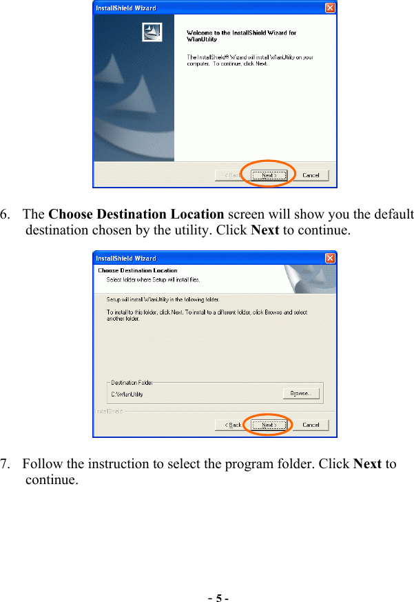
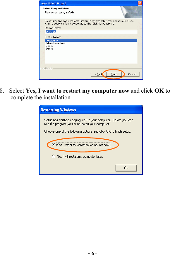
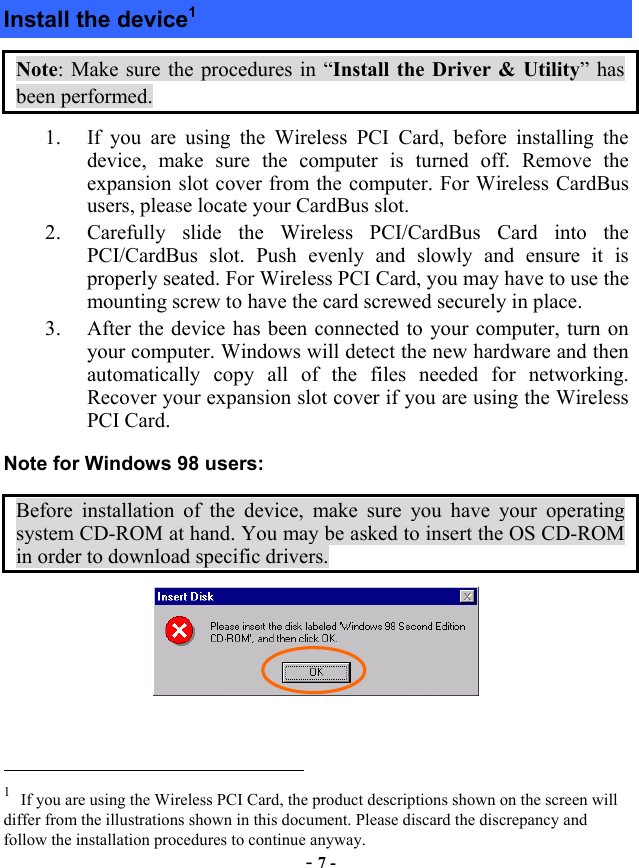
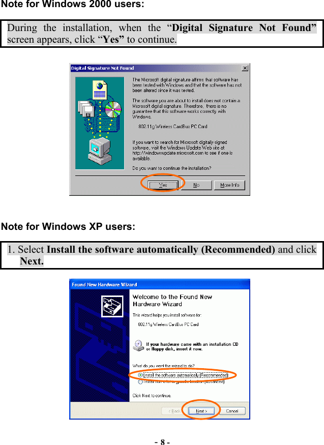
Users Manual
2.
OEM Installation Manual
3.
Antenna Installation Manual
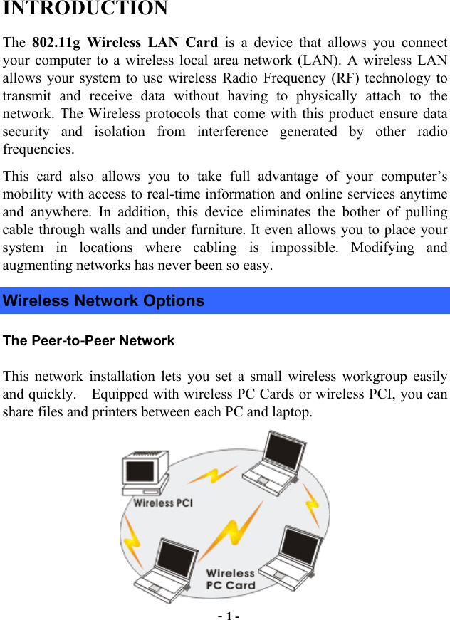
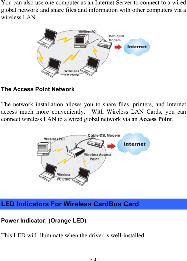
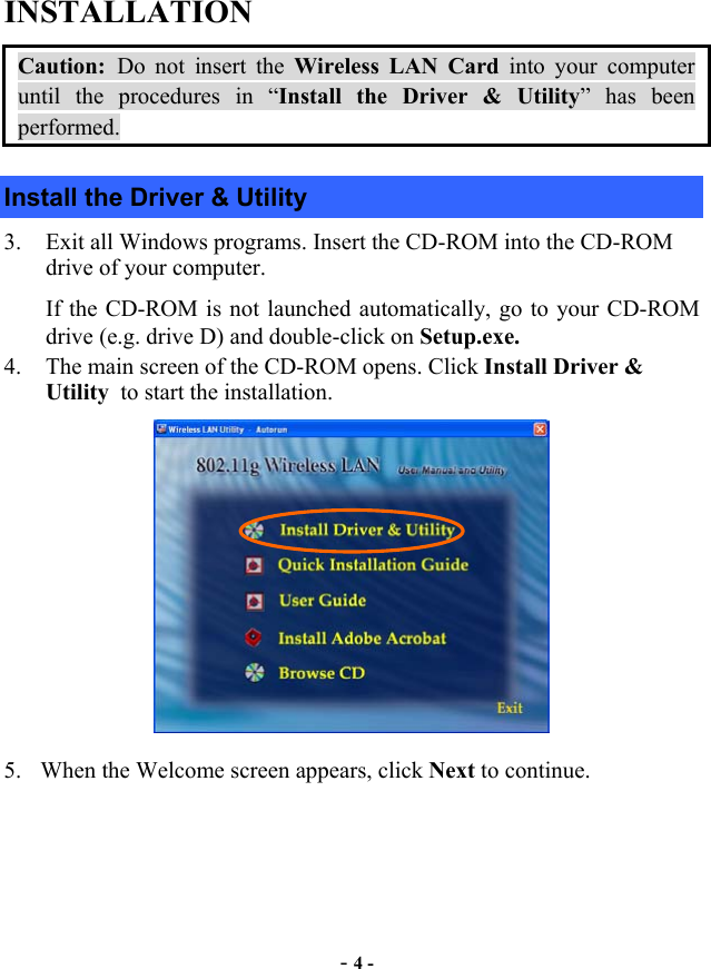
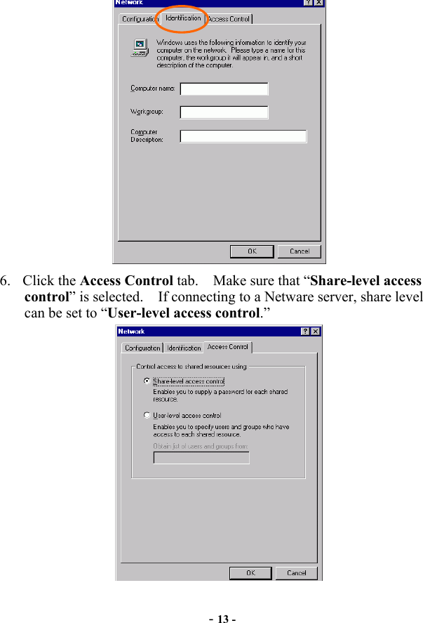
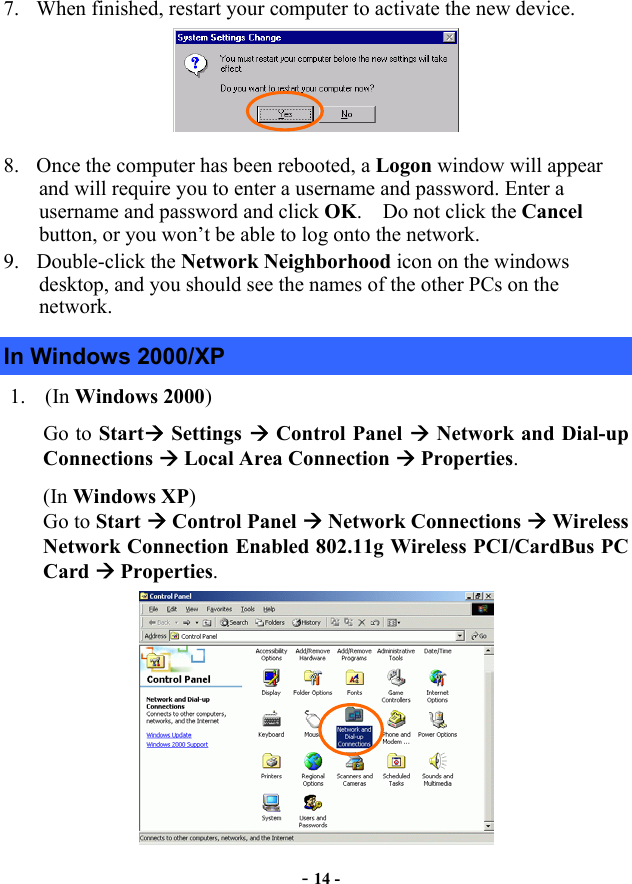
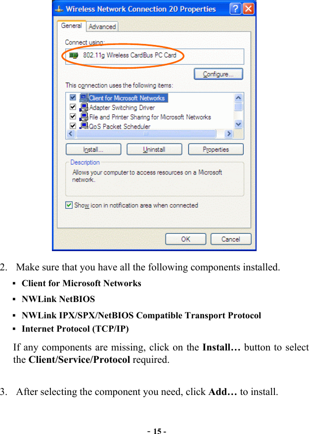
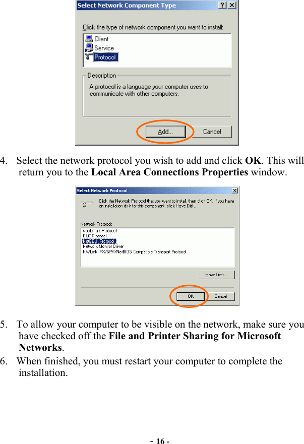
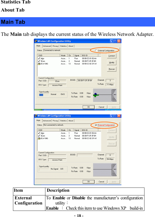
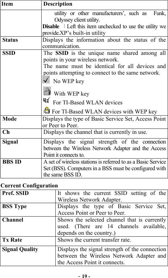
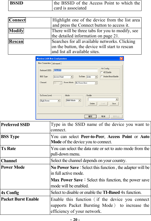
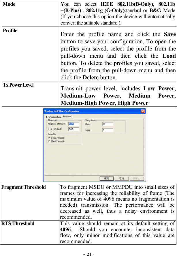
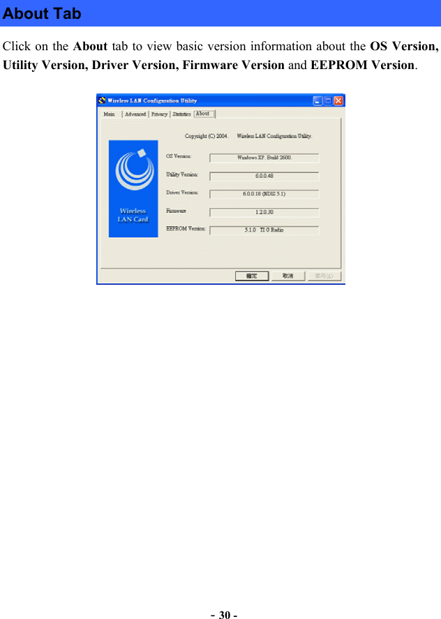
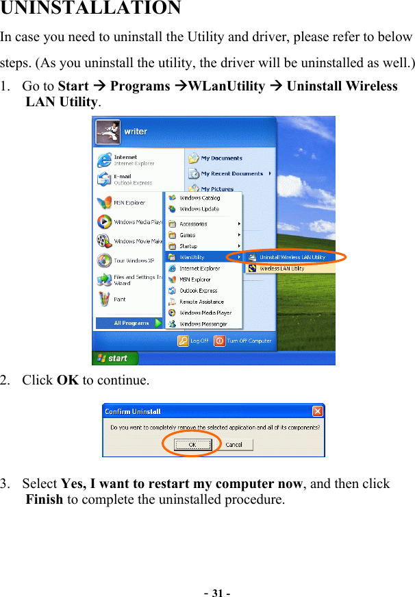
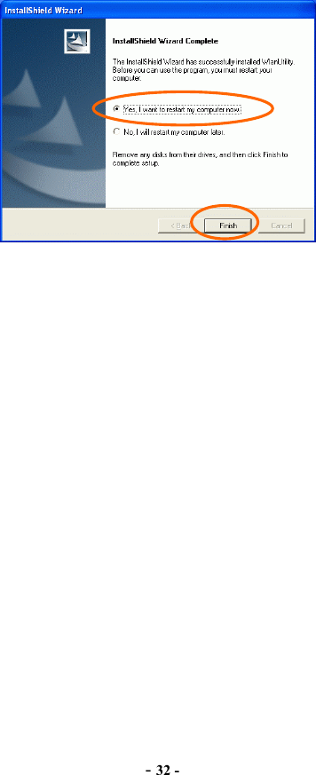
Users Manual
Navigation menu
Upload a User Manual
Namespaces
Wiki Guide
HTML
PDF
Info
Views
User Manual
Discussion / Help
Navigation