Abocom Systems WPG2401 802.11g Wireless LAN PCI Card User Manual 802
Abocom Systems Inc 802.11g Wireless LAN PCI Card 802
Users Manual
802.11g
Wireless LAN Card
User’s Manual
Federal Communication Commission Interference Statement
This equipment has been tested and found to comply with the limits for
a Class B digital device, pursuant to Part 15 of the FCC Rules. These
limits are designed to provide reasonable protection against harmful
interference in a residential installation. This equipment generates,
uses and can radiate radio frequency energy and, if not installed and
used in accordance with the instructions, may cause harmful
interference to radio communications. However, there is no guarantee
that interference will not occur in a particular installation. If this
equipment does cause harmful interference to radio or television
reception, which can be determined by turning the equipment off and
on, the user is encouraged to try to correct the interference by one of
the following measures:
- Reorient or relocate the receiving antenna.
- Increase the separation between the equipment and receiver.
- Connect the equipment into an outlet on a circuit different from that
to which the receiver is connected.
- Consult the dealer or an experienced radio/TV technician for help.
This device complies with Part 15 of the FCC Rules. Operation is
subject to the following two conditions: (1) This device may not cause
harmful interference, and (2) this device must accept any interference
received, including interference that may cause undesired operation.
FCC Caution: Any changes or modifications not expressly approved by
the party responsible for compliance could void the user's authority to
operate this equipment.
IMPORTANT NOTE:
FCC Radiation Exposure Statement:
This equipment complies with FCC radiation exposure limits set forth
for an uncontrolled environment. This equipment should be installed
and operated with minimum distance 20cm between the radiator & your
body.
This transmitter must not be co-located or operating in conjunction with
any other antenna or transmitter.
AboCom declared that WPG2401 is limited in CH1~11 from 2400 to
2483.5 MHz by specified firmware controlled in USA.
Table of Contents
INTRODUCTION...................................................................................................1
WIRELESS NETWORK OPTIONS ...............................................................................1
The Peer-to-Peer Network.........................................................................1
The Access Point Network ........................................................................2
LED INDICATORS FOR WIRELESS CARDBUS CARD.................................................2
Power Indicator: (Orange LED).................................................................2
Act Indicator: (Green LED).......................................................................2
INSTALLATION ....................................................................................................3
INSTALL THE DRIVER & UTILITY ............................................................................3
INSTALL THE DEVICE ..............................................................................................6
Note for Windows 98 users: ......................................................................6
Note for Windows XP users: .....................................................................7
Verify Device Installation..........................................................................8
NETWORK CONNECTION .................................................................................9
IN WINDOWS 98/ME ..............................................................................................9
IN WINDOWS 2000/XP .........................................................................................12
CONFIGURATION ..............................................................................................15
ACCESSING THE CONFIGURATION UTILITY............................................................15
MAIN TAB............................................................................................................16
PROFILE MANAGER TAB.......................................................................................25
INFORMATION TAB ...............................................................................................26
ABOUT TAB..........................................................................................................28
UNINSTALLATION.............................................................................................29
- 1 -
INTRODUCTION
The 802.11g Wireless LAN Card is a device that allows you connect your
computer to a wireless local area network (LAN). A wireless LAN allows your
system to use wireless Radio Frequency (RF) technology to transmit and receive
data without physically attaching to the network. The Wireless protocols that
come with this product ensure data security and isolation from interference
generated by other radio frequencies.
This card also allows you to take full advantage of your computer’s mobility with
access to real-time information and online services anytime and anywhere. In
addition, this device eliminates the bother of pulling cable through walls and
under furniture. It even allows you to place your system in locations where
cabling is impossible. Modifying and augmenting networks has never been so
easy.
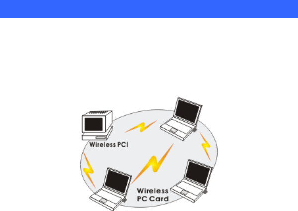
Wireless Network Options
The Peer-to-Peer Network
This network installation lets you set a small wireless workgroup easily and
quickly. Equipped with wireless PC Cards or wireless PCI, you can share files
and printers between each PC and laptop.
- 2 -
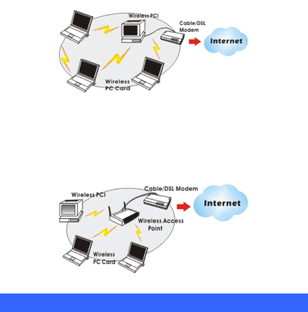
You can also use one computer as an Internet Server to connect to a wired global
network and share files and information with other computers via a wireless LAN.
The Access Point Network
The network installation allows you to share files, printers, and Internet access
much more conveniently. With Wireless LAN Cards, you can connect wireless
LAN to a wired global network via an Access Point.
LED Indicators For Wireless CardBus Card
Power Indicator: (Orange LED)
The power LED will appear as solid orange when the Wireless PC card is
connected with an AP. If the Wireless PC card is not connected with an
AP, the power LED will be blank.
Act Indicator: (Green LED)
The Act LED will be blinking green when transmitting/receiving wireless data.
- 3 -
INSTALLATION
Caution: Do not insert the Wireless LAN Card into your computer
until the procedures in “Install the Driver & Utility” has been
performed.
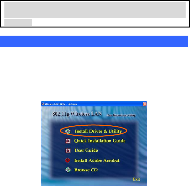
Install Driver & Utility
3. Exit all Windows programs. Insert the CD-ROM into the CD-ROM
drive of your computer.
If the CD-ROM is not launched automatically, go to your CD-ROM drive
(e.g. drive D) and double-click on Setup.exe.
4. The main screen of the CD-ROM opens. Click Install Driver &
Utility to start the installation.
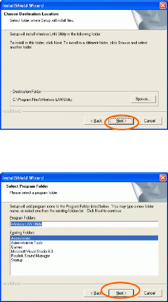
5. When the Welcome screen appears, click Next to continue.
120
6. The Choose Destination Location screen will show you the default
destination chosen by the utility. Click Next to continue.
- 4 -
7. Follow the instruction to select the program folder. Click Next to
continue.
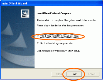
9. Select Yes, I want to restart my computer now and click Finish to
complete the software installation.
- 5 -
- 6 -
Install the device1
Note: Make sure the procedures in “Install Driver & Utility” has been
performed.
1. If you are using the Wireless PCI Card, before installing the
device, make sure the computer is turned off. Remove the
expansion slot cover from the computer. For Wireless CardBus
users, please locate your CardBus slot.
2. Carefully slide the Wireless PCI/CardBus Card into the
PCI/CardBus slot. Push evenly and slowly and ensure it is
properly seated. For Wireless PCI Card, you may have to use
the mounting screw to have the card screwed securely in place.
3. After the device has been connected to your computer, turn on
your computer. Windows will detect the new hardware and then
automatically copy all of the files needed for networking.
Recover your expansion slot cover if you are using the Wireless
PCI Card.
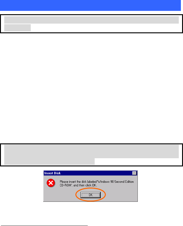
Note for Windows 98 users:
Before installation of the device, make sure you have your operating
system CD-ROM at hand. You may be asked to insert the OS CD-ROM
in order to download specific drivers.
1 If you are using the Wireless PCI Card, the product descriptions shown on the screen will
differ from the illustrations shown in this document. Please discard the discrepancy and
follow the installation procedures to continue anyway.
- 7 -
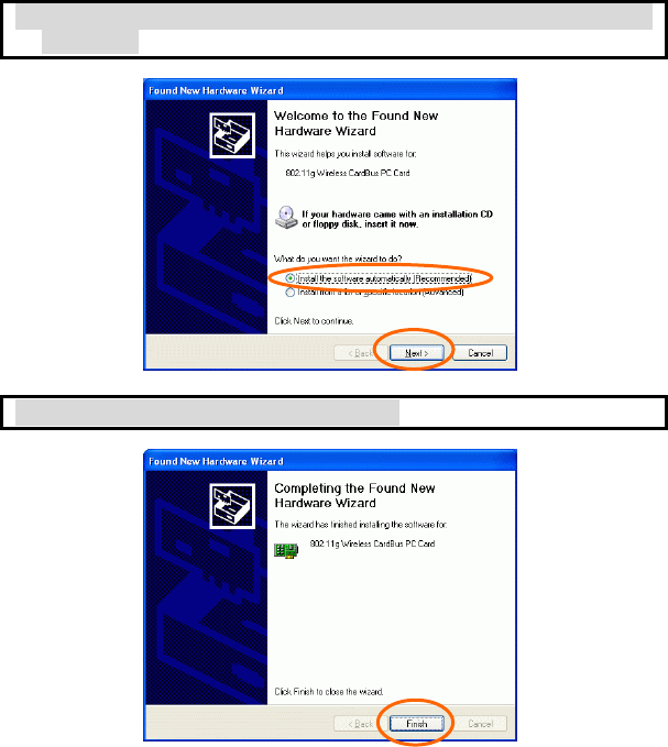
Note for Windows XP users:
1. Select Install the software automatically (Recommended) and
click Next.
4. Click Finish to complete the installation.
- 8 -
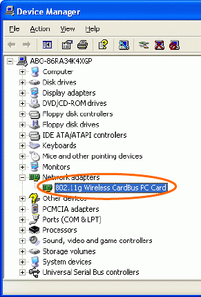
Verify Device Installation
To verify that the device has been properly installed in your computer and is
enabled, go to Start Settings Control Panel System ( Hardware)
Device Manager. Expand the Network adapters item. If the 802.11g Wireless
PCI/CardBus PC Card is listed, it means that your device is properly installed
and enabled.
- 9 -
NETWORK CONNECTION
Once the driver has been installed, you will need to make adjustments to your
network settings.
In Windows 98/ME
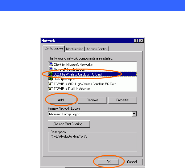
1. Go to Start Settings Control Panel Network.
2. Make sure that you have all the following components installed.
802.11g Wireless PCI / CardBus PC Card
IPX/SPX-compatible Protocol
NetBEUI
TCP/IP
- 10 -
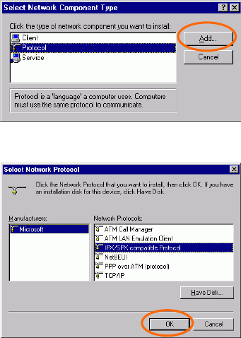
If any components are missing, click on the Add button to install them. All of the
protocols and clients required (listed above) are provided by Microsoft.
3. Next, highlight the specific network component you need, click Add.
4. Highlight Microsoft, and then double click on the item you want to
add. Click OK.
After returning to the Network screen, you can make your computer is visible
on the network by enabling the File and Print Sharing.
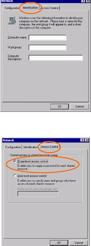
5. Click the Identification tab. Enter a name that is unique on the
network. Type the name of your workgroup, which should be the
same name used by all of the other PCs on the network.
- 11 -
6. Click the Access Control tab. Make sure that “Share-level access
control” is selected. If connecting to a Netware server, share level
can be set to “User-level access control.”
- 12 -
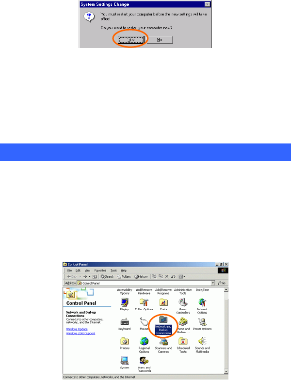
7. When finished, restart your computer to activate the new device.
8. Once the computer has been rebooted, a Logon window will appear
and will require you to enter a username and password. Enter a
username and password and click OK. Do not click the Cancel
button, or you won’t be able to log onto the network.
9. Double-click the Network Neighborhood icon on the windows
desktop, and you should see the names of the other PCs on the
network.
In Windows 2000/XP
1. (In Windows 2000)
Go to Start Settings Control Panel Network and Dial-up
Connections Local Area Connection Properties.
(In Windows XP)
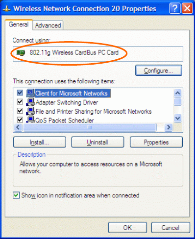
Go to Start Control Panel Network Connections Wireless
Network Connection Enabled 802.11g Wireless PCI/CardBus PC Card
Properties.
- 13 -
2. Make sure that you have all the following components installed.
Client for Microsoft Networks
NWLink NetBIOS
NWLink IPX/SPX/NetBIOS Compatible Transport Protocol
Internet Protocol (TCP/IP)
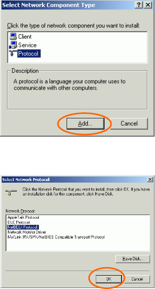
If any components are missing, click on the Install… button to select the
Client/Service/Protocol required.
3. After selecting the component you need, click Add… to install.
- 14 -
4. Select the network protocol you wish to add and click OK. This will
return you to the Local Area Connections Properties window.
5. To allow your computer to be visible on the network, make sure you
have checked off the File and Printer Sharing for Microsoft
Networks.
6. When finished, you must restart your computer to complete the
installation.
- 15 -
CONFIGURATION
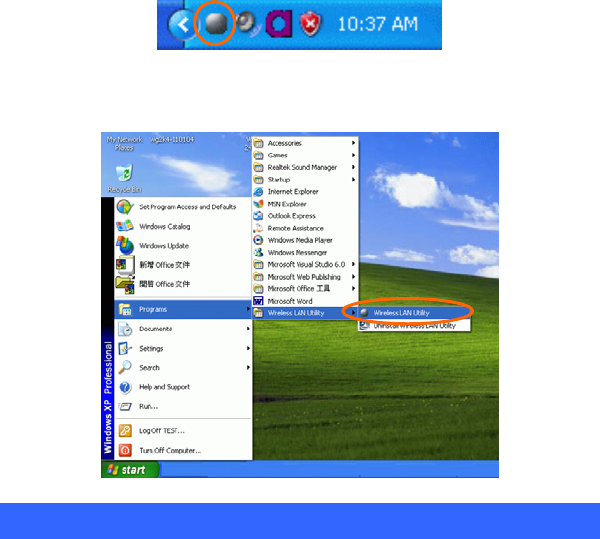
After successful installation of the Wireless LAN Card’s driver, the utility icon
will display in the task bar. You will be able to access the Configuration Utility
through the Network Status icon.
If the icon doesn’t appear automatically, go to Start Programs Wireless
LAN Utility Wireless LAN Utility, it will appear in the task bar.
Accessing the Configuration Utility
All settings are categorized into 4 Tabs:
Main Tab
Profile Manager Tab
Information Tab
About Tab
- 16 -
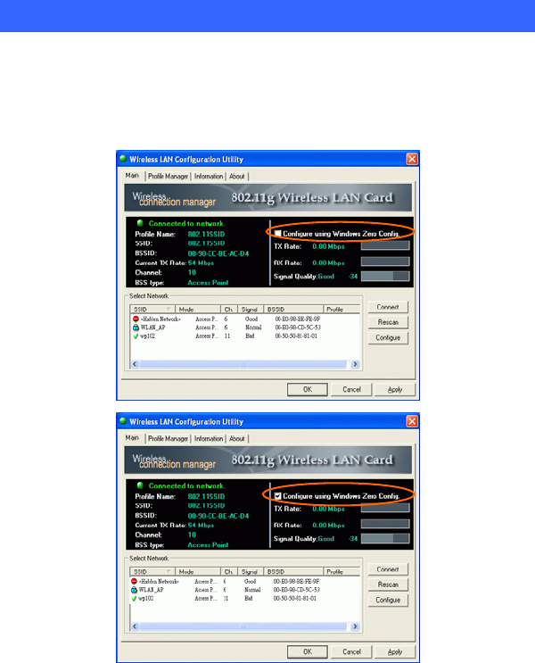
Main Tab
The main tab enables you to scan for available networks, select a network to
which to connect, modify the settings for the current connection, or set up your
station for Ad Hoc connection.

- 17 -
Note:Only one configuration utility can be active at a time. When the ZCU is set
to be the active utility, opening the TI utility-by double-clicking on the utility
icon in the system tray or right-clicking the icon and selecting Open-launches
the ZCU inserted of the TI utility.
Configure using
Windows Zero Config.
External Configuration Checkbox (Windows XP
only): A checkbox that enables you to disable the
WLAN Station Configuration Utility and indicates
that the station driver is to be configured with
Windows XP’s built-in Zero Configuration Utility
(ZCU).
On Windows XP systems, the ZCU service is
automatically stopped when the WLAN utility is
installed. The ZCU is started when you check the
Configure using Windows Zero Configuration
checkbox.
The checkbox is only displayed on Windows XP
systems.
Profile name The profile name that is currently connected.
SSID The SSID is the unique name shared among all points
in your wireless network.
The name must be identical for all devices and points
attempting to connect to the same network.
Indicates that the network does not require special
security settings and access rights in order to
connect to it (that is, you can connect to the
network by setting the station’s privacy mode to
None and authentication mode to None.)
Indicates that the network requires special security
settings and access rights in order to connect to it.
Indicates a hidden network which is not
- 18 -
broadcasting its SSID. The SSID for such networks
are listed as <Hidden Network>. In order to connect
to such a network, you must know the network’s
SSID.
BBS ID The MAC address for the Access Point or station.
Current Tx Rate It displays the currently connected rate.
Channel The channel that is currently connected.
BSS type The type of connection, either Access Point or
Peer-to-Peer.
Tx Rate /Rx Rate The actual instantaneous transmit and receive rates, in
Mbps.
Signal quality The signal strength from the network Access Point or
station. The strength is displayed in three formats: a
signal quality level (one of five levels, from Bad to
Best), a numerical value in dBm, and a signal quality
bar graph with a scale of –82 to –10.
Connect Highlight one of the devices from the list area and
press the Connect button to access it.
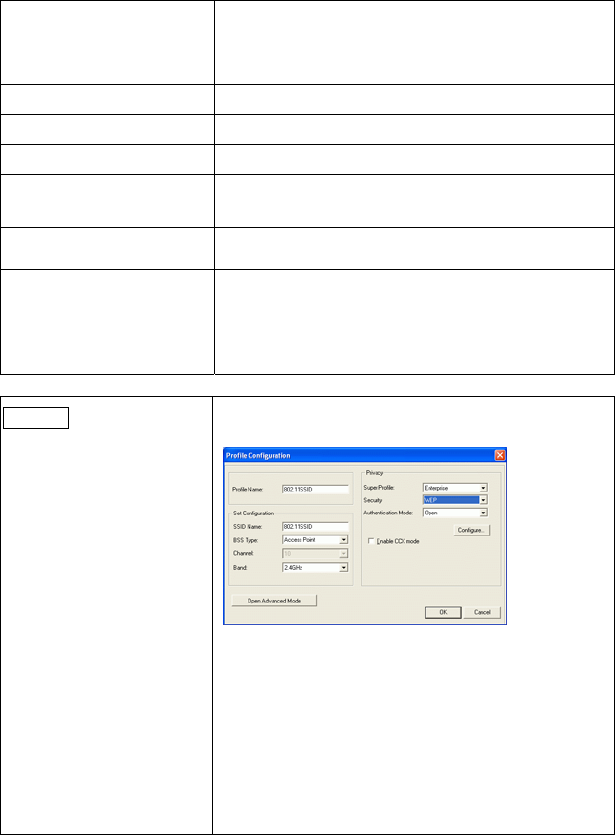
Profile Name:Enter the profile name you wish to have.
Set Configuration :The Set Configuration area
contains the following fields
SSID Name:The SSID for the current profile
BSS Type:The BSS type, either peer-to-
p
eer or Access
Point
Channel:The preferred channel on which to make a
connection (available for peer-to-
p
eer connections
only)
- 19 -
Band:The band on which to make a connection.
Super Profile :Determines the security settings
available to you, and can be one of the following:
Personal: Enables only the basic security settings that
you are likely to need at home.
Enterprise: Enables all security settings, including
more complex certificate-
b
ased settings that you may
need in an office.
Security:Determines the type of security to use for
this connection, and can be one of the following:
None
WEP
WPA2
Any WPA
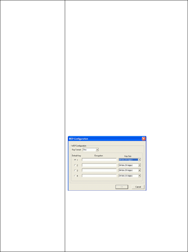
WEP:WEP (Wired Equivalent Privacy) is a data
security mechanism based on a 64 Bit/128 Bit/256 Bit
shared key algorithm.
Press the Configure button to change WEP
configuration.
Note: You must use the same Default Key #, Key Size,
and Encryption Key on both the host and destination
devices in order to establish a connection.
KEY1 ~ KEY 4:You can specify up to 4 different
keys, but only one can be used at a time.
Encryption:Enter the key value in this field.
A key of 10 hexadecimal characters (0-9, A-F) is
required if a 64-bit Key Size is selected.
- 20 -
A key of 26 hexadecimal characters (0-9, A-F) is
required if a 128-bit Key Size is selected.
A key of 58 hexadecimal characters (0-9, A-F) is
required if a 256-bit Key Size is selected.
WPA2 & Any WPA:(WiFi Protected Access)is more
secure than WEP, and should be used if possible.
Authentication Mode :Determines the type of
authentication to use for this connection.
With Super Profile set to Personal, this field can be
one of the following:
Open : If your access point/wireless router is using
"Open " authentication, then the wireless adapter will
need to be set to the same authentication type.
Shared Key: Shared Key is when both the sender and
the recipient share a secret key.
Auto Switch: Select Auto Switch for the adapter to
automatically select the appropriate
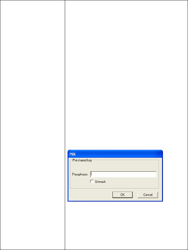
PSK:In the Passphrase field, enter the key that you
are sharing with the network for the WLAN
connection. By default, the key that you type is
masked with asterisks (*). To view the key that you
entered, check Unmask.
With Super Profile set to Enterprise, this field can
also be one of the following:
TLS
PEAP – MS-CHAP-V2 (only with CCX mode
enabled)
PEAP – GTC (only with CCX mode enabled)
- 21 -
LEAP (only with CCX mode enabled)
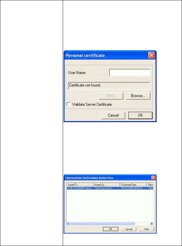
The Personal Certificate window enables you to
supply a personal certificate for use with TLS and
PEAP – MS-CHAP-V2 authentication.
This window is only applicable with Enterprise
security.
Personal Certificate
:
To supply a personal certificate:
1. In the User Name field, type in the user name
assigned to the certificate.
2. Select a certificate by clicking Browse. The
standard Windows Select Certificate window is
displayed:
3. Select a certificate from the list, and click OK. The
name of the certificate is dis
p
la
y
ed in the textbox in
- 22 -
the middle of the Personal Certificate window.
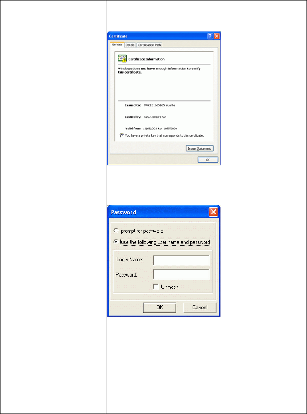
4. To view the certificate, click View. The certificate
is displayed:
The Password window enables you to supply a login
name and password for use when selecting LEAP or
PEAP – GTC authentication.
To specify a user name and password:
1.Select the appropriate radio button to indicate
whether:
You are supplying a user name and password now.
The utility prompts you for them each time you try
to connect to a network.
2. To provide a user name and password now, enter
them in the fields provided.
Not all values for Authentication Mode are available
- 23 -
for all Security settings.
Enable CCX mode:Enables connections in CCX
mode. When checked, additional authentication modes
are available.
This checkbox is only enabled when Super Profile is
set to Enterprise.
Configure :Click Configure to open the
configuration window.
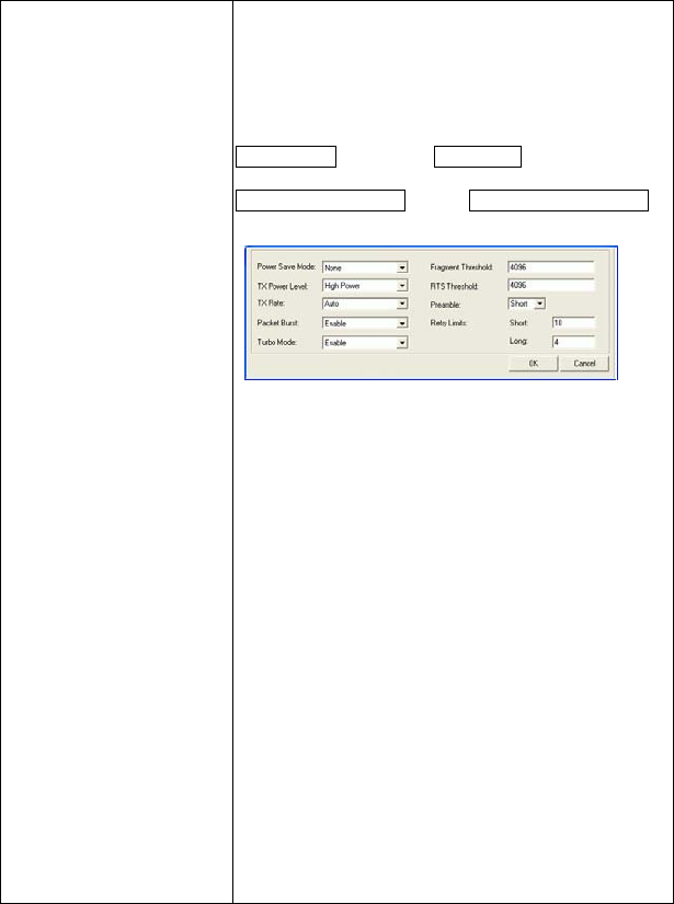
Open Advanced Mode:Click Open Advanced Mode to
configure the following screen:
Power Save Mode: Indicates whether to use power
saving. This field can be one of the following:
♦ None:No power save mode.
♦ Max :Max power save mode.
TX Power Level: The transmit power level, which
can be one of the following:
♦ Low Power (6% of full power)
♦ Medium-Low Power (12%)
♦ Medium-Power (25%)
♦ Medium-High Power (50%)
♦ High Power (100%)
TX Rate: The preferred rate of transmission, in Mbps.
The options for this field are based on the selected
band and channel,
Packet Burst: Indicates whether the Packet Bursting
feature is enabled.
Turbo Mode: Indicates whether the 4X feature is
enabled.
Fragment Threshold: The maximum fragment
length, in bytes. The value is an even number from
256 to 4096 (default is 4096).

- 24 -
RTS Threshold: The minimum packet length for
sending an RTS frame, in bytes. The value must be
greater than 0 (default is 4096).
Preamble: Either short or long
Retry limits: The number of retries to attempt, if
necessary, when sending a frame. There are two Retry
limits fields:
Short: For frames without an RTS frame
Long: For frames with an RTS frame
To hide the advanced fields, click Close Advanced
Mode.
OK:When the configuration is done, click OK to
save.
Cancel:Click Cancel to discard changes.
Rescan Searches for all available networks. Clicking on the
button, the device will start to rescan and list all
available sites.
Configure Click Configure to modify the settings for the
profiles with the SSID of the selected network.
If no profile exists, the Profile Configuration window
is displayed so that you can create a profile. The
Profile Name field is blank
If no profile exists, the Profile Configuration window
is displayed so that you can modify its settings.
OK Click OK to save your settings.
Cancel Click Cancel to discard changes.
Apply Click Apply to save any changes to profiles and
connection settings.
- 25 -
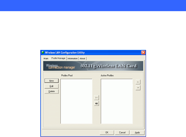
Profile Manager Tab
The Profile Manager enables you to create, modify and delete the profiles that the
station uses to connect to WLAN networks, to activate and de-activate profiles,
and to raise and lower a profiles’s priority.
All profiles are displayed in one of the following lists:
Profiles Pool: A list of inactive profiles, that is, profiles that cannot currently be
used for making a connection.
Active Profiles: A list of active profiles, that is, profiles that can be used for
making a connection.
Each profile in the Active Profiles list has a priority based on its location in the list.
The higher in the list, the higher the profile’s priority.
When the station tries to connect to a network with a specific SSID, the station first
tries to connect to the network using the profile with the highest priority (that is, the
profile highest in the list of active profiles) that is set to the selected SSID. If the
station cannot connect using the first profile, the station tries to connect using the
next-highest profile, and so forth.
Likewise, when the station loses the connection with the current network, the station
tries to make a connection with any available network for which a profile exists.
The station first tries to connect to a network using the profile with the highest
- 26 -
priority. If the station cannot connect using the first profile, the station tries to
connect using the next-highest profile, and so forth.
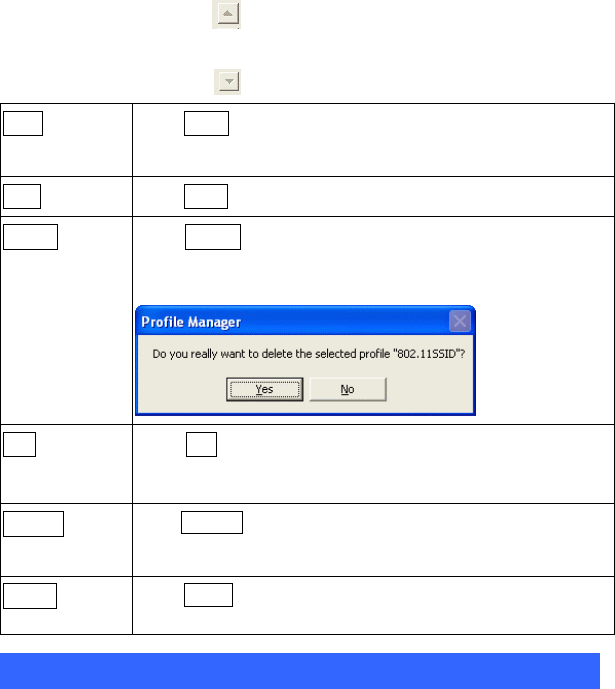
To move a profile up one spot in the Active Profiles list, select the profile by
clicking on it, and then click
To move a profile down one spot in the Active Profiles list, select the profile by
clicking on it, and then click
New Click New to create a new profile.
The new profile is inactive and is added to the Profiles Pool list.
Edit Click Edit to edit an exiting profile.
Delete Click Delete to delete the profile that is currently selected
in the Profile Manager tab. The following confirmation
dialog box is displayed:
OK Click OK to save any changes to profiles and connection
settings, and then minimizes the utility to the Windows
system tray
Cancel Click Cancel to discard any changes to profiles and connection
settings, and then minimizes the utility to the Windows system
tray.
Apply Click Apply to save any changes to profiles and connection
settings.
Information Tab
The Information tab displays information maintained by the driver, such as the
number of packet errors and the total number of bytes received or transmitted. The
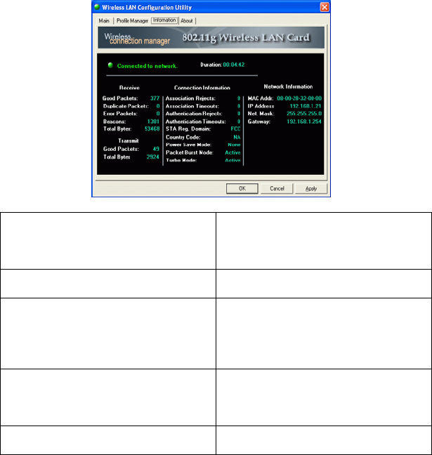
- 27 -
tab also displays information about the current connection, as well as network
information about the station. The statistics are for the period starting when you last
connected to a network. The statistics are refreshed at least twice a second.
Connection Status
Indicates whether the station is currently
connected to a network. This is the same
connection status as displayed on the
Main tab.
Duration The time since the station last connected
to a network.
Receive / Transmit Statistics All information is for the period starting
when you last connected to a network,
except for Beacons, which is for the
period starting when you installed the
driver.
Connection Information Information about association and
authentication attempts with the
currently selected network, as well as
some connection settings.
Network Information Network information, such as the IP
address, of the station.
- 28 -
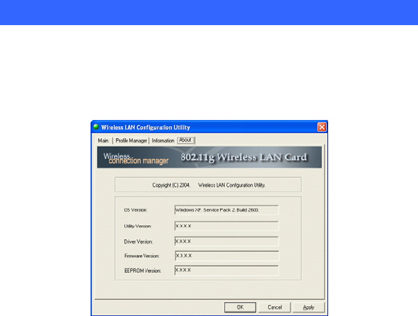
About Tab
Click on the About tab to view basic version information about the OS Version,
Utility Version, Driver Version, Firmware Version and EEPROM Version.
- 29 -
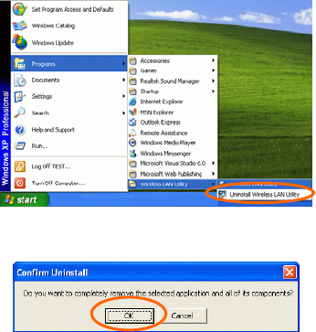
UNINSTALLATION
In case you need to uninstall the Utility and driver, please refer to below steps.
(As you uninstall the utility, the driver will be uninstalled as well.)
1. Go to Start Programs Wireless LAN Utility Uninstall
Wireless LAN Utility.
2. Click OK to continue.
3. Click Finish to complete the uninstalled procedure.