Abocom Systems WR404 Wireless VPN Router User Manual WR404MNL new
Abocom Systems Inc Wireless VPN Router WR404MNL new
Manual
Wireless VPN Router
802.11g/802.11b Wireless Access Point
Broadband Internet Access
4-Port Switching Hub
User’s Manual

i
Table of Contents
CHAPTER 1 INTRODUCTION.............................................................................1
Wireless VPN router Features......................................................................................1
Package Contents..........................................................................................................1
Physical Details.............................................................................................................2
CHAPTER 2 INSTALLATION..............................................................................4
Requirements................................................................................................................4
Procedure......................................................................................................................4
CHAPTER 3 CONFIGURATION..........................................................................6
Setup Wizard................................................................................................................7
Check the Network Connection....................................................................................9
CHAPTER 4
CONFIGURATION VIA WEB.........................................................................................10
Internet Port...............................................................................................................10
Local Port....................................................................................................................15
Advanced Setup..........................................................................................................17
Network Status............................................................................................................25
Others.........................................................................................................................26
1
Chapter 1
Introduction
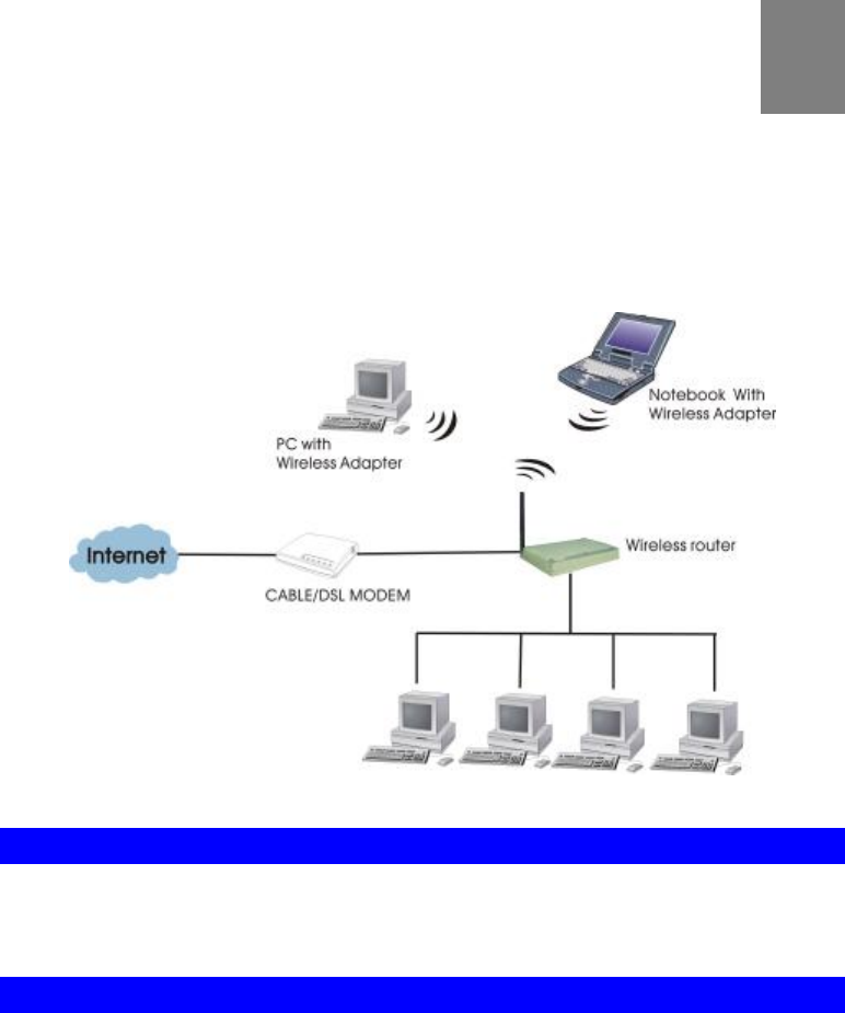
Congratulations on the purchase of your new Wireless Router. The Wireless VPN router is a
multi-function device providing the following services:
• Shared Broadband Internet Access for all LAN users.
• 4-Port Switching Hub for 10BaseT or 100BaseT connections.
• Wireless Access Point for 802.11b and 802.11g Wireless Stations.
Figure 1: Wireless VPN Router Application Map
Wireless VPN router Features
The Wireless VPN router incorporates many advanced features, carefully designed to provide
sophisticated functions while being easy to use.
Package Contents
The following items should be included:
• The Wireless VPN router Unit
• Power Adapter
• Quick Installation Guide
• CD-ROM containing the on-line manual.
If any of the above items are damaged or missing, please contact your dealer immediately.
1
2
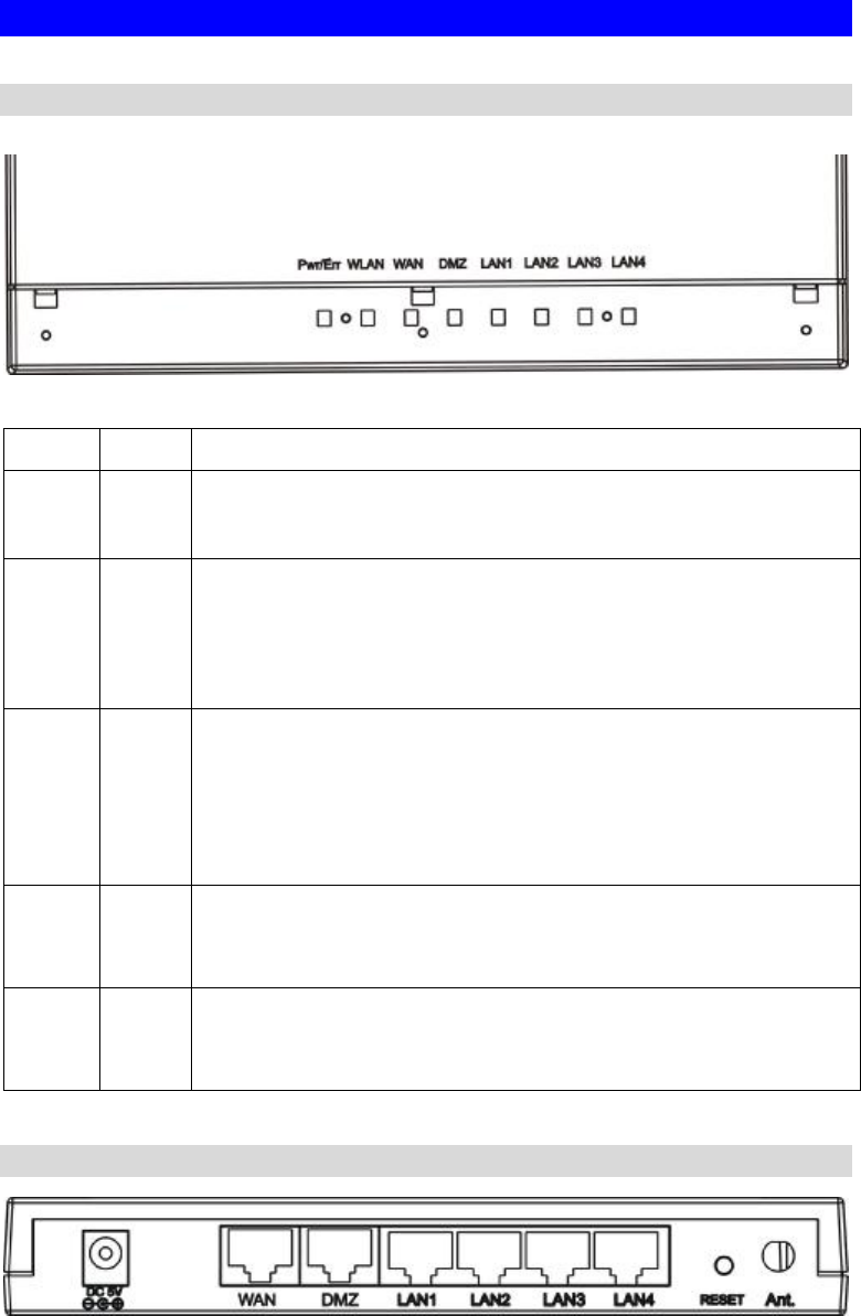
Physical Details
Front-mounted LEDs
Figure 2: Front Panel
Color Status
Pwr/Er
r Green On - Power on.
Off - No power.
WAN Green On - Connection to the Broadband Modem attached to the WAN port is
established.
Off - No connection to the Broadband Modem.
Flashing - Data is being transmitted or received via the WAN port.
WLAN
Green On - Wireless connection available; Wireless Access Point is ready for
use.
Off - No Wireless connection available.
Flashing - Data is being transmitted or received via the Wireless access
point. Data includes "network traffic" as well as user data.
LAN
(1-4)
Green
On -Linked to LAN
Off - No link to LAN
Flashing - Data is being transmitted or received via LAN
DMZ Green
On -Linked to DMZ
Off - No link to DMZ
Flashing - Data is being transmitted or received via DMZ
Rear Panel
Figure 3: Rear Panel

3
Power port
(DC 5V) Connect the supplied power adapter here.
10/100BaseT
LAN port Use standard LAN cables (RJ45 connectors) to connect your PCs to
these ports.
If required, any port can be connected to another hub. Any LAN port
will automatically function as an "Uplink" port when necessary.
WAN port
(10/100BaseT) Connect the DSL or Cable Modem here. If your modem came with a
cable, use the supplied cable. Otherwise, use a standard LAN cable.
Reset Button
4
Chapter 2
Installation
Requirements
• Network cables. Use standard 10/100BaseT network (UTP) cables with RJ45 connectors.
• TCP/IP protocol must be installed on all PCs.
• For Internet Access, an Internet Access account with an ISP, and either of a DSL or
Cable modem (for WAN port usage)
• To use the Wireless Access Point, all Wireless devices must be compliant with the
IEEE802.11b or IEEE802.11g specifications.
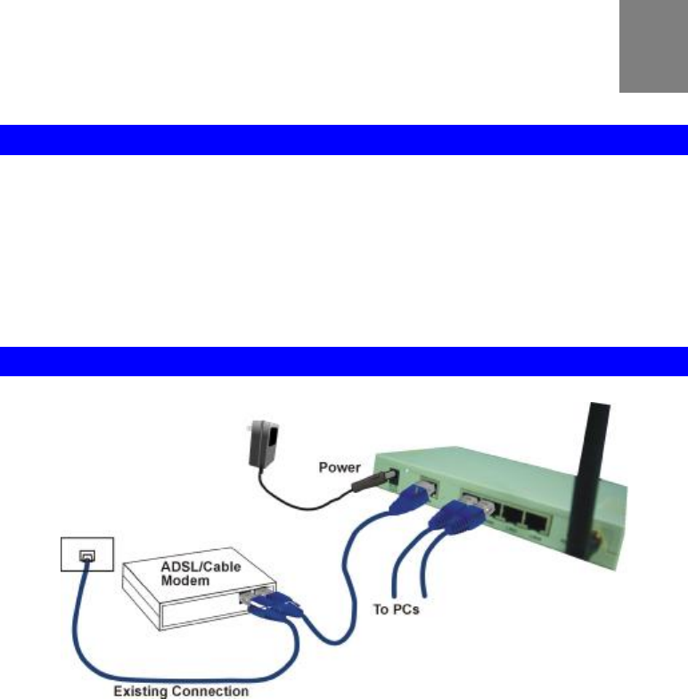
Procedure
Figure 4: Installation Diagram
1. Choose an Installation Site
Select a suitable place on the network to install the Wireless Router.
Ensure the Wireless VPN router and the DSL/Cable modem are powered OFF.
2. Connect LAN Cables
Connect PCs to the LAN ports on the Wireless VPN router with standard LAN cables
(RJ-45).
3. Connect WAN Cable
Connect the DSL or Cable modem to the WAN port on the Wireless Router. Use the cable
supplied with your DSL/Cable modem. If no cable was supplied, use a standard cable.
4. Power Up
• Power on the Cable or DSL modem.
• Connect the supplied power adapter to the Wireless VPN router and power up.
Use only the power adapter provided. Using a different one may cause hardware damage
2
5
5. Check the LEDs
• The Power LED should be ON.
• For each LAN (PC) connection, the LAN should be ON (provided the PC is also ON.)
• The WAN LED should be ON.
• The WLAN LED should be ON

6
NOTE
!
Chapter 3
Configuration
Before setting up the Wireless Router, make sure your PCs are configured to "Obtain an IP
(or TCP/IP) address automatically".
For Windows 2000 & XP Users
1. Go to Start à Control Panelà Network and Internet Connectionsà (Right-click
on) Local Area Connectionà Properties
2. Make sure the box next to Internet Protocol (TCP/IP) is checked. Click the Internet
Protocol (TCP/IP) and click the Properties button.
3. Select "Obtain an IP address automatically".
Select "Obtain DNS server address automatically".
Then click OK to complete the PC configuration.
4. Restart your computer.
3
7
Setup Wizard
For Windows 2000 & XP users, your computer should obtain an IP Address automatically
from the Wireless Router's DHCP Server, after you've done the above steps and restarted
your computer.
1.Start your WEB browser. In the Address box, enter the following:
HTTP://192.168.1.254
Figure 5
2. Press the Setup Wizard on the upper left screen to configure the router.
Figure 6
3. Refer to the data from your ISP and the following table, please select the type of Internet
Access you want. And then follow the instructions on the screen to continue.
Figure 7
The type of
Internet
Access
Type of
connection
Data Required
PPPoE
(DSL dynamic
mode)
PPPoE Please enter “ Login name” and “ Password”.
DHCP
(CATV dy-
namic mode)
DHCP Usually you don’t need to enter any data, but
some ISP
may require a particular Hostname, Domain name
.
Please enter the data required.
Static configu-
ration Static IP
For static IP users, please enter the data provided by
your ISP including IP address, Subnet Mask, Gateway,
8
Primary DNS and Secondary DNS.
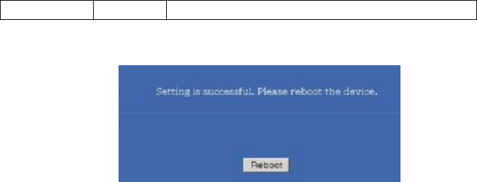
4. Please press Reboot after the configuration is completed and wait for a moment for
Network connection checking.
Figure 8
9
Check the Network Connection
After the installation is completed, you can open a new browser to surf the Internet.
If the browser fails to open the web page, you can check the Internet connection by following
the steps below:
1. On the browser’s “address” field, type in 192.168.1.254 and click “Go”.
2. Leave both “User Name” and “Password” blank and press“Ok”.
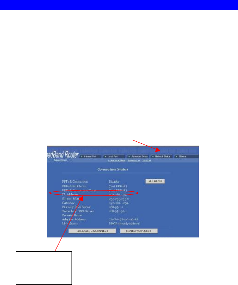
3. On the screen, select “Network status” tab on the upper right hand screen.
4. Locate “IP address” on the screen.
• If the IP address is not 0.0.0.0 (as illustrated below), the Internet connection is established.
• If the IP address is 0.0.0.0, that means the Internet connection test fails. Please check
your data, the Cable/DSL modem, and all connection. Make sure you have entered all
data correctly. Repeat the Setup Wizard described above.
Figure 9
Network Status
The Internet
connection is
established.
10
Chapter 4
Configuration via Web
In the setup home page, you can set your preference from Internet Port (CATV dynamic
Mode, PPPoE, Static configuration, PPTP), Local Port, Advanced Setup(Management,
Virtual Server, Packet Filter, Static Route, Dynamic DNS, URL Blocking) Network
Status (Connection Status, Session List, Users List,), and Others (Factory Reset, Save
Configuration, Firmware Upgrade. )
Internet Port
The opening screen contains settings for the Internet connection interface. Click on the
down arrow 6 to select the desired Internet connection mode on the list.
Obtain configuration automatically
(CATV dynamic mode) For users who are using Cable Modem
Internet service.
PPPoE (DSL dynamic mode) For users who are using xDSL Inter-
net service that runs PPPoE. If your
xDSL service uses PPPoE, after
installing the Router, do not run
PPPoE software on your computers.
Static configuration Select this item when the ISP assigns
static IP address for your account.
PPTP (DSL dynamic mode)
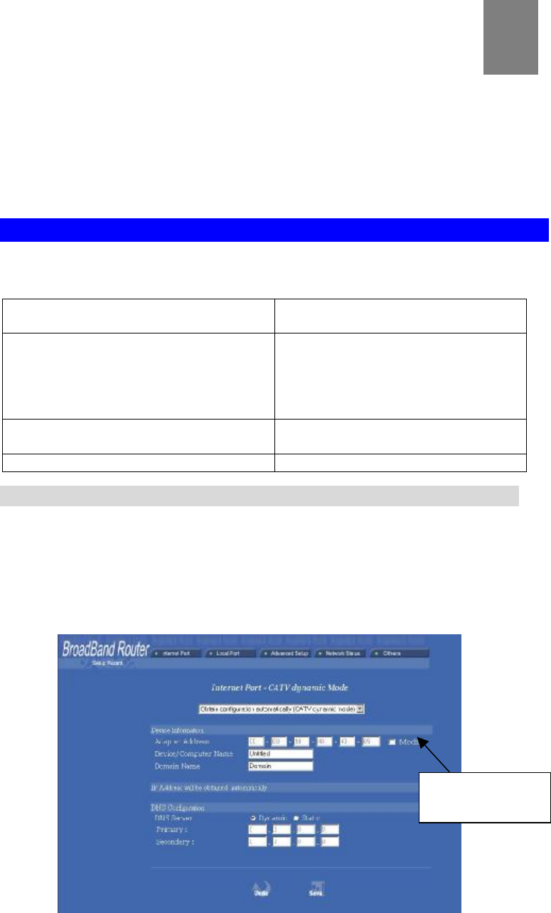
CATV dynamic Mode
Selecting this mode enables you to obtain dynamic IP address from your ISP via DHCP
support. Once the IP address is obtained, you can access the Internet.
For most cases, this page needs no input. However, some ISPs may require some infor-
mation for identification purpose. For example: Device/Computer name and Domain
Name; please enter the information required to complete the settings.
4
Check to modify
the MAC address

11
Figure 10
Device Information
Adapter Address This field is grayed out, because the Adapter Address is
not supposed to be entered randomly. Do Not change the
content unless you are sure it is necessary to modify your
MAC address. To modify the address; check Modify
and enter the desired MAC address.
Device/Computer
Name
Enter a descriptive name for identification purpose. Some
Internet Service Providers (ISP) requires this information
and if that is the case, they will provide you with the
name.
Domain Name For example: yourcompany.com. The maximum input
for this field is 32 alphanumeric characters and it is case
insensitive. Note: 1. Your ISP may ask you to input a
certain domain name. 2. Domain name is also required
for internal network’s email and news functions.
DNS Configuration This field is grayed out for the IP address is obtained
dynamically
DNS Server Select Dynamic or Static. Enter the information of
Primary and Secondary DNS Server provided by your
ISP when Static configuration is selected.
Undo Click Undo to clear all the settings on this page.
Save After completing the settings on this page, click Save to
save the settings.
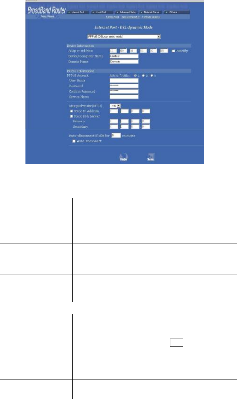
PPPoE (DSL dynamic Mode)
If this mode is selected and settings are saved, this Router will be connected to the
Internet over an always-on connection by a method provided by PPPoE.
PPPoE offers simulated dial-up, which save users’ time and effort to run the program on
their PCs. And the auto-connect/disconnect feature lets the system to stay idle when
there’s no activity, but pick up the connection in no time when there’s network activity.
This can significantly save users’ cost on connection fees.
The MTU function lets you choose the maximum packet size that fits your need for
optimal throughput. To reduce the packet size can help connecting to certain web sites or
speeding up packet to be received/sent.
12
Figure 11
Device Information
Adapter Address This field is grayed out, because the Adapter Address is
not supposed to be entered randomly. Do Not alter the
content unless you are sure it is necessary to modify your
MAC address. To modify the address, check Modify
and enter the desired MAC address.
Device/Computer
Name
Enter a descriptive name for identification purpose. Some
Internet
Service Providers (ISP) requires this information and if
that is the case, they will provide you with the name.
Domain Name For example: yourcompany.com. The maximum input for
this field is 32 alphanumeric characters and it is case
insensitive
PPPoE Information
PPPoE Account Active Profile ¤1 ¤2 ¤3 You can set up to three
PPPoE accounts, while only one account can be enabled at
a time. To set the profile, select the profile number, enter
all the information, and then click on Save. The device
will save the information, restart and return to the previ-
ous menu page. If you don’t see the saved information on
the screen, click on the “Internet Port” to refresh the
screen.
Username Maximum input is 52 alphanumeric characters (case
sensitive)

13
Password Maximum input is 36 alphanumeric characters (case
sensitive)
Confirm Password Re-enter your password for confirmation.
Service Name For identification purpose. If it is required, your ISP will
provide you with the information.
MAX PACKET SIZE
(MTU) Max packet size (MTU): Click the down arrow 6 to select
the most appropriate MSS (maximum segment size;
default value is 1492) for your application. Reducing the
packet size can help connecting to certain web sites or
speeding up packet transfer rate. If the incorrect selection
is selected, you may not be able to open certain web sites.
Static IP Address: Enter the IP address provided by your ISP.
Static DNS Server Enter the primary and secondary DNS addresses provided
by your ISP.
Auto-disconnect if
idle for minutes
Configure this device to disconnect the PPPoE connection
when there is no activity for a predetermined period of
time.
• Default: 5 minutes. You can input any number from 0
to 65535.
• To keep the line always connected, set the number to
0.
Auto-reconnect Check to enable auto-reconnected with PPPoE line. This
function allows the device to automatically reconnect
when the line is disconnected due to ISP problem.
Save After completing the settings on this page, click Save to
save the settings.
Undo Click Undo to clear all the settings on this page.
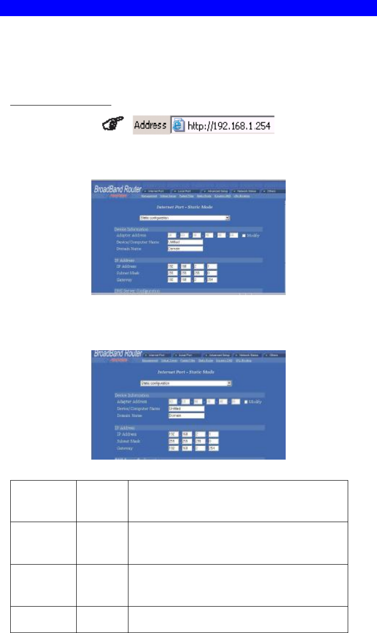
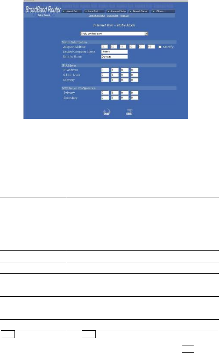
Static Configuration
For leased line users, information provided by their ISPs has to be filled in the below
respective fields when this mode is selected. Information from your ISP includes: IP
address, Subnet Mask, Gateway, primary DNS, secondary DNS, note that there may be
more than one IP address from your ISP, select one address and enter it in the corre-
sponding field.
14
Figure 12
Device Information
Adapter Address This field is grayed out, because the Adapter Address is
not supposed to be entered randomly. Do Not alter the
content unless you are sure it is necessary to modify your
MAC address. To modify the address, check Modify
and enter the desired MAC address.
Device/Computer
Name
Enter a descriptive name for identification purpose. Some
Internet Service Providers (ISP) requires this information
and if that is the case, they will provide you with the name
Domain Name For example: yourcompany.com. The maximum input for
this field is 32 alphanumeric characters and it is case
insensitive
IP Address
IP Address Enter the information provided by your ISP.
Subnet Mask Enter the information provided by your ISP.
Gateway Enter the information provided by your ISP.
DNS Server Configuration
Primary/Secondary Enter the information provided by your ISP.
Undo
Click Undo to clear all the settings on this page.
Save After completing the settings on this page, click Save to
save the settings.
15
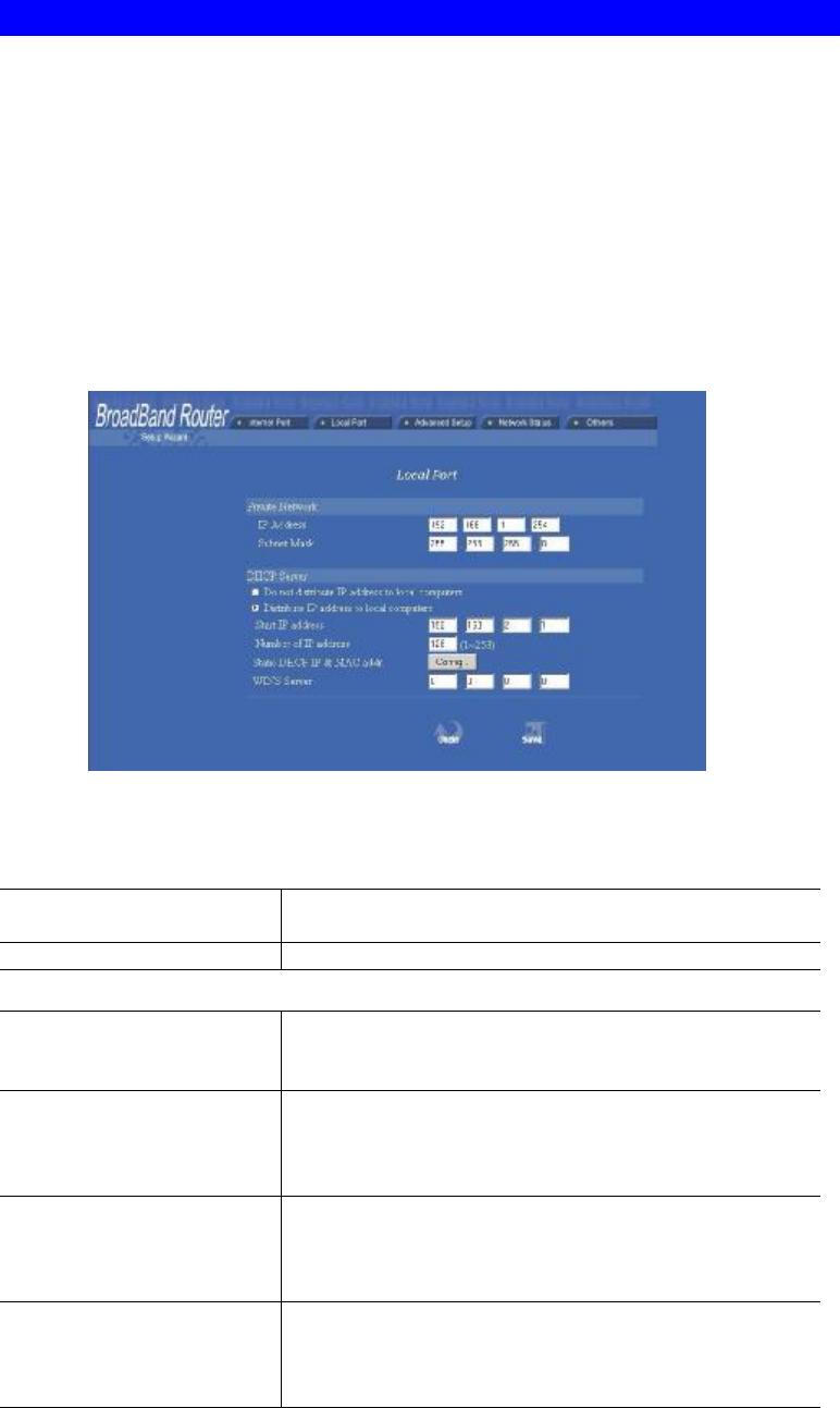
Local Port
This screen contains settings for LAN interface attached to the local network. You can
set to distribute IP address to local PCs or not.
If “Distribute IP address to local computer” is selected, users can assign IP addresses
for computers on LAN. The number of IP address decides the number of clients allowed
to obtain IP addresses. Note that all the PC on the same LAN should use the same
subnet Mask.
Users can also set Static DHCP in this page. Users are allowed to set 32 Static DHCP.
Using this feature, the device will assign the same IP address to a computer (according to
the network adapter’s MAC address) and this computer becomes the only one able to
request that IP address. This is quite useful to set virtual serveres which requires
particulary fixed IP for outside Internet access.
Figure 13
Private Network
IP Address Default: 192.168.1.254 (this is the local address of this
Router)
Subnet mask Default: 255.255.255.0
DHCP Server
Do not distribute IP
address to local com-
puters
Checking this radio button to disable this Router to
distribute IP Addresses (DHCP Server disabled)
Distribute IP addresses
to local computers Checking this radio button to enable this Router to
distribute IP Addresses (DHCP enabled). And the
following field will be activated for you to enter the
starting IP Address
Start IP address The starting address of this local IP network address
pool. The pool is a piece of continuous IP address
segment. Keep the default value 192.168.1.1 should
work for most cases.
Number of IP address • Maximum: 253. Default value 253 should
work for most cases.
Note: If “Continuous IP address poll starts” is set at
192.168.1.1 and the “Number of IP address in pool” is
16
253, the device will distribute IP addresses from
192.168.1.1 to 192.168.1.253 to all the computers in
the network that request IP addresses from DHCP
server (Router)
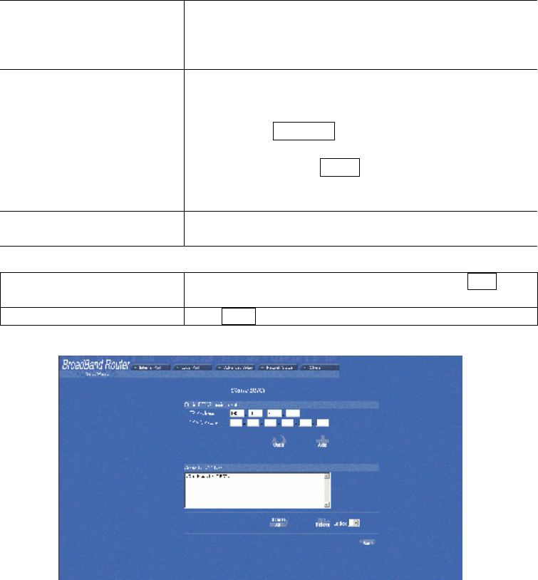
Static DHCP IP&MAC
addr Click the Config. button to enter the Static DHCP
page. Enter IP and Network adapter MAC addresses
for Static DHCP and click the Add button to save the
settings. Click Delete All to clear all entries. Click the
Index drop-down menu to select the desired entry
number and then click Delete to delete only the
selected one. You can add up to 32 static DHCP IPs.
Click Back to return to the Local Port page to continue
WINS server When necessary, enter the IP Address of the Windows
domain name server.
Save After completing the settings on this page, click Save
to save the settings.
Undo Click Undo to clear all the settings on this page.
Figure 14
17
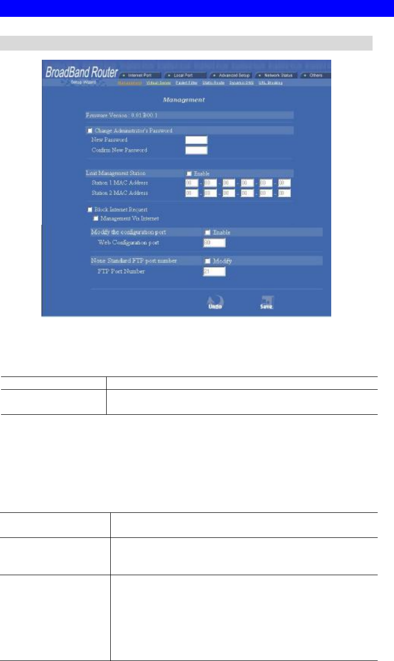
Advanced Setup
Management
Figure 15
Change Administrator’s password: change the password for the device.
New Password Enter the new password.
Confirm New
Password Re-enter the new password for confirmation.
Limit Management
Click to enable this function.
Enables two stations to manage this IP Share through Web configuration. Enter the
MAC addresses of the stations you selected for management. After the setup is
completed, only the assigned stations with correct password authentication can manage
this IP Share device.
Section 1 MAC
Address Enter the first management station’s network adapter
MAC addresss.
Section 2 MAC
Address Enter the second management station’s network adapter
MAC address. If you are only setting up one management
station, leave Station 2 MAC address with all F.
Block Internet
Request Click to enable this function.
Blocks requests from Internet to the local network. If this
item is checked, the function of management through Web
configuration will be disabled. In other words, Internet
requests and the HTTP management, namely ICMP,
IDENT, and HTTP will be rejected.

18
Management via
Internet Allows management of this device via HTTP from Inter-
net. This field will be automatically disabled when Block
Internet Request is checked. If Block Internet Request is
not enabled, you can choose to enable/disable this
function.
Below are coordinate results of Block Internet Request and HTTP management for this
device. Refer to this table for further Internet/system management.
V: Checked
O: Unchecked
Block Internet
Request Manageme
nt Via
Internet
Coordinate Result
V O
(automatical
ly)
WAN requests over TCP 113 (IDENT) and
ICMP are rejected.
HTTP management is not allowed.
O V WAN requests over TCP 113 (IDENT) and
ICMP are accepted.
HTTP management is allowed.
O O WAN requests over TCP 113 (IDENT) and
ICMP are accepted.
HTTP managements is not allowed.
Modify the configuration port Enable
Check to modify web configuration port number settings.
Web Configuration port Input the port number for web configuration. The default web
port for configuration is set to 80. If you want to set the port to
other port, input that port number and click SAVE. Once the
web configuration was modifiied, configuation over web
should be changed with the new setting; e.g. if the web
configuration port was set to 8080, to login the web
configuration, you need to input the address like:
http://192.168.1.254:8080 (where 192.168.1.254 is Router’s
local port IP address.)
None Standard FTP Port Number
Check to modify FTP port port number setting.
FTP Port Number
The standard FTP port is set to port 21. You can set it to other
port as long as they are free to use.
Save changing the setting(s), click Save to save the setting(s)
Undo Click Undo to clear all the settings on this page.
Virtual Server
In this page, you can set up a local server with specific port number that stands for the
service (e.g. web(80), FTP(21), Telnet(23)). When this device receives an incoming
access request for this specific port, it will be forwarded to the corresponding internal
server. You can add virtual servers by either port numbers or by names.
19
Maximum 24 Server entries are allowed and each port number can only be assigned to
one IP address.
NOTE: Setting up Virtual Server is like opening the firewall, which exposes your
network to users on the Internet. Which means the IP Share’s NAT will no longer be
able to provide protection from hackers.
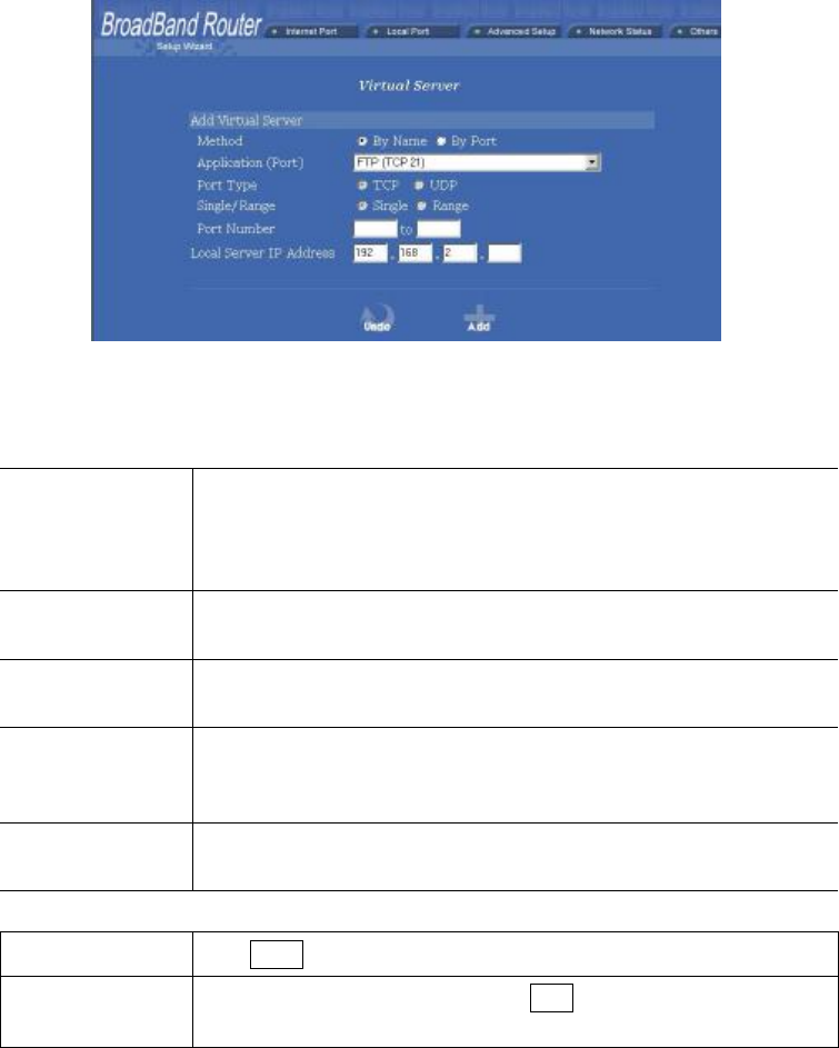
Figure 16
Add Vitural Server
Method
¤By Name
¤ By Port
You can select to set up a virtual server either by name or by port
number.
Application
(Port) Select and click ▼ to scroll down. Select from the most popular
server applications for Virtual Server.
Port Type Select the port type (TCP or UDP) for the port number that was
entered earlier.
Single/Range,
Port Number For selecting a specific port or a range of ports which you want
the Internet users to be able to access. The valid port number
ranges from 0 to 65535.
Local Server
IP Address Enter the Local Server’s IP address (for the specified port entered
above).
Undo Click Undo to clear all the settings on this page.
Add Each time you finished setting, click Add and the added servers
will appear on the Server List.
20
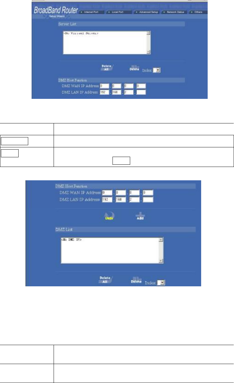
Figure 17
Server List Display all the virtual servers.
Delete All Click to delete all the servers on the list.
Delete Click the Index drop-down menu to select the desired server
number and then click Delete to delete only the selected server.
Figure 18
DMZ Host Function:
If the DMZ Host Function is enabled, it means that you set up DMZ host at a particu-
lar computer to be exposed to the Internet so that some applications/software,
especially Internet / online game can have two-way connections. You can enter up to
four DMZ Hosts in the device.
DMZ WAN
IP Address
Enter the WAN IP Address set for DMZ Host.
DMZ LAN IP
Address
Enter the local IP address mapping to the client computer, which
you want to use as the DMZ Host computer.
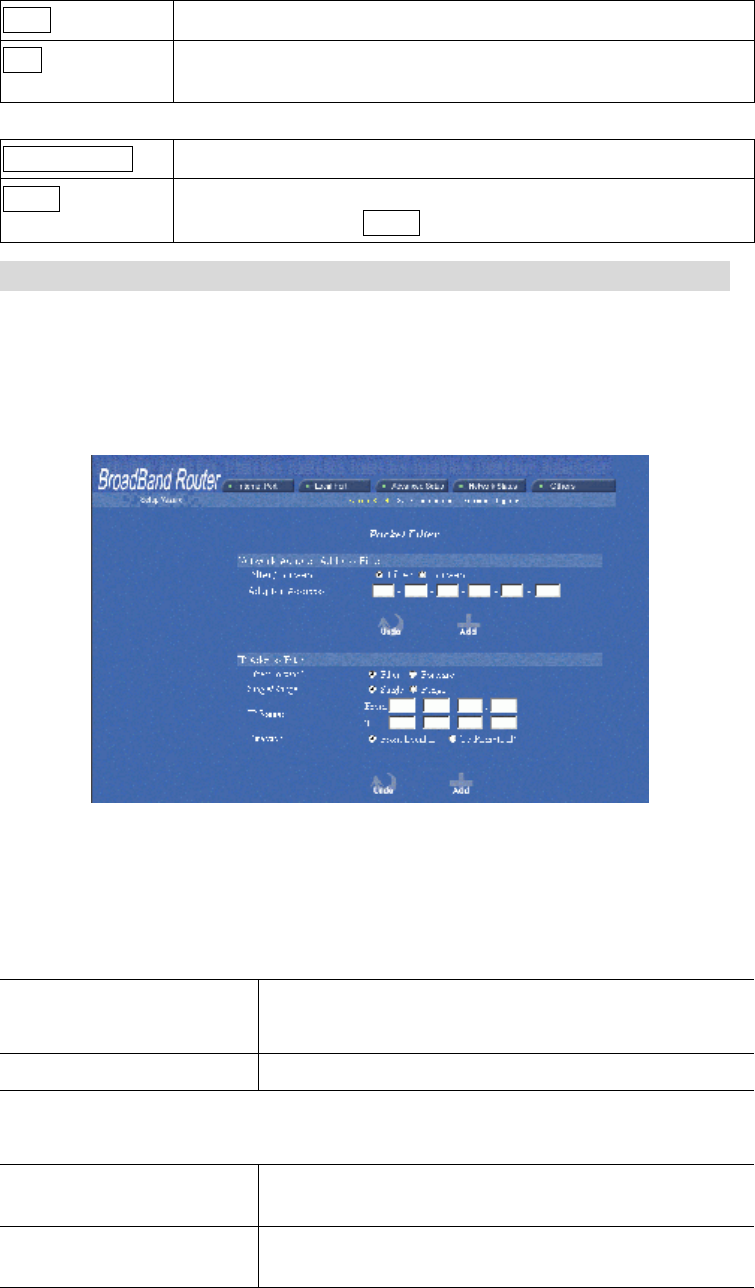
21
Undo Click to clear all the settings on this page.
Add After completing the settings on this page, click “Add” to save
the settings.
DMZ List Display all the DMZ hosts.
DELETE ALL Click to delete all the DMZ host(s) on the list.
Delete Click on the Index drop-down menu to select the desired host
number and then click Delete to delete only the selected host.
Packet Filters
In the Packet Filters setup screen, you can block specific internal users from accessing
the Internet and you can also disable specific Internet services.
You can set up the filters through the following two filters: Network Adapter Address
(MAC address) and IP Address. Each filter can be set to Filter (drop) or Forward
(pass) packets. You can input up to 24 filters in this device.
Figure 19
NETWORK ADAPTER ADDRESS FILTER
Filter according to local computer’s network adapter MAC address (also known as the
adapter card’s Physical Address).
¤ FILTER ¤ FORWARD
SELECT TO FILTER OR FORWARD FOR THE
FOLLOWING ADAPTER ADDRESSES.
ADAPTER ADDRESS ENTER THE DESIRED ADAPTER ADDRESSES.
IP Address Filter
Filter with computer’s IP address.
Filter/Forward Select to Filter or Forward for the following IP Ad-
dresses.
Single/Range You can filter a single IP, or a range of the IP ad-
dresses.
22
IP Range Enter the Start and End IP addresses for a range of IP
addresses for filter/forward.
Direction
¤From Local IP
¤To Remote IP
Filtering IP address of a local computer; or filtering IP
address of a remote server (this remote server connects
to the device via Internet).
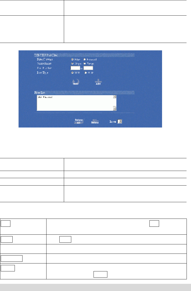
Figure 20
TCP/UDP Port Filter
Filter using the port number. You can set filter for a single port or a range of ports.
Filter/Forward Select to Filter or Forward for the following assigned
port(s).
Single/Range You can filter a single port, or a range of ports
Port Number The port number(s) for the filters.
Port Type •TCP •UDP: filter according to the Connection-
Based Application Service on the remote server
using the port number.
Add Each time you finished setting the filters, click the Add button and
the added filter will appear on the Filter List
Undo Click Undo to clear all the settings in this categrory
Filter List Display all the Packet Filters.
Delete All Click to delete all the filters on the list.
Delete Click on the Index drop-down menu to select the desired filter
number and then click Delete to delete only the selected filter.
Static Route
You can set static routes to manually administrate the network topology/traffic when the
dynamic route is not effective enough.
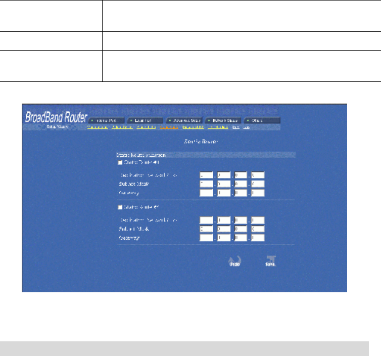
23
To set static routers, select “Static Route #1” or “Static Route #2”, enter the settings.
You can refer to the following two example applications for settings. When finished,
click “Save” to save settings. Click “Undo” to clear all entries.
Static Route #
Destination Network
Host
The network address of the remote LAN Segment.
Network Mask The network mask for the remote LAN Segment.
Gateway The IP address of the gateway which this router must use to
communicate with the destination above.
Figure 21
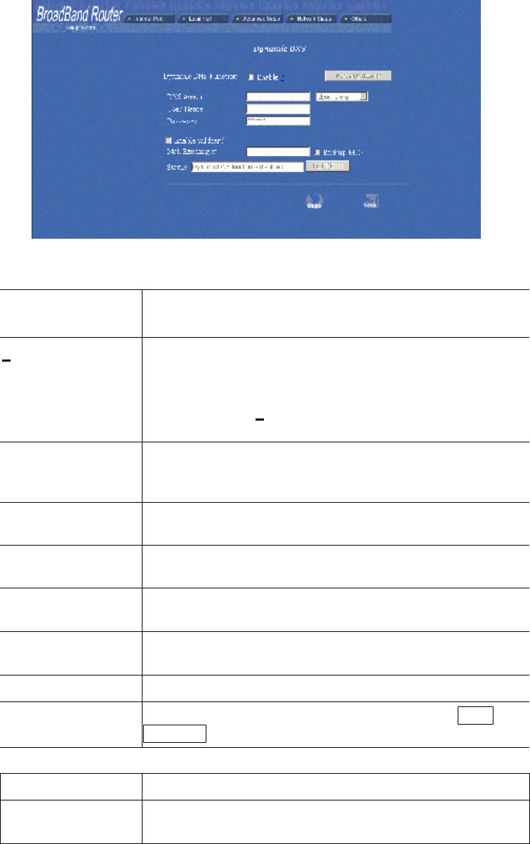
Dynamic DNS
The Dynamic DNS (require Dynamic DNS Service) enables you to alias a dynamic IP
address to a static hostname, this allows your device to be more easily accessed by
specific name. When this function is enabled, the IP address in Dynamic DNS Server
will be automatically updated with the new IP address provided by ISP.
24
Figure 22
o Dynamic DNS
Enable
Click to enable this function and make the settings available.
? Click on the question mark to find out more about Dynamic DNS
Service.
Note: If you don’t already have the Dynamic DNS Service,
please click on the
? and then follow the instructions to sign up
for the serv
ice.
DNS Account Enter your host domain name. Click the down arrow 6 to select
your Dynamic DNS client with which you registered for the ser-
vice.
User Name Enter your user name, which was registered with the Dynamic
DNS client.
Password Enter your password, which was registered with the Dynamic DNS
client.
o Enable Wildcard Check to enable the Wildcard function. To know more about
Wildcard, please refer to FAQ section.
Mail Exchanger To know more about MX (Mail Exchanger), please refer to FAQ
section.
Backup MX? Check to have Backup MX service enabled.
Status Displays the results of the action. If action failed, click Force
Update IP to enable the function.
Undo Click to clear all the settings on this page.
Save After completing the settings on this page, click Save to save
the settings.
25
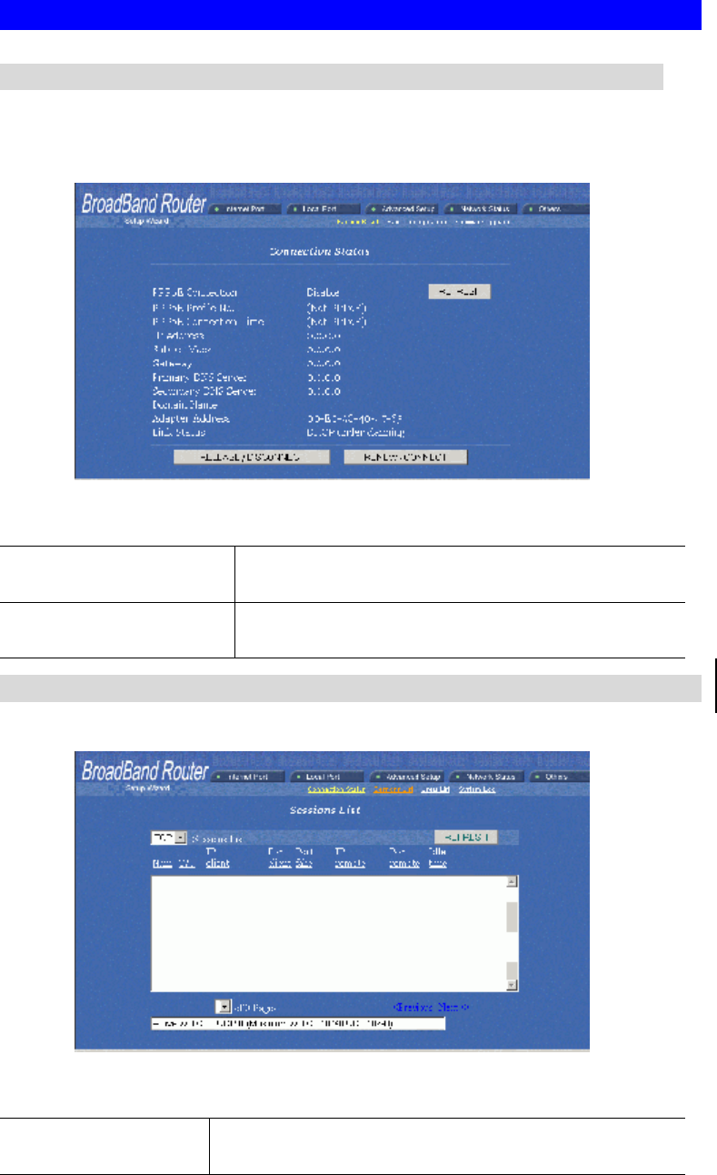
Network Status
Connection Status
Display the current Internet connection status. After the device is connected to the
Internet Service, you will see IP, Subnet Mask, Gateway and DNS IP addresses on the
table.
Figure 23
RELEASE/DISCONNECT Click on this button to disconnect from ISP and release all
the IP information on the Internet Port.
RENEW/CONNECT
Click on this button to reconnect to the ISP and renew all IP
information on the Internet Port.
Sessions List
Displays active Internet sessions through this device.
Figure 24
REFRESH Click on this button to refresh the list and get the latest
session list.
26
T/U Display TCP or UDP port type.
IP Client/ Port
Client
The local network IP address/port number of one end point of
the session.
Port Fake Featuring NAT, the Port Fake is used to translate the local
network IP addresses for connecting to the Internet.
IP Remote/Port
Remote
The outside network IP address/port number of the other end
of the session.
Idle The idle time of the session. If the idle time is too long (more
than 15 minutes), the device will disconnect the idled session.
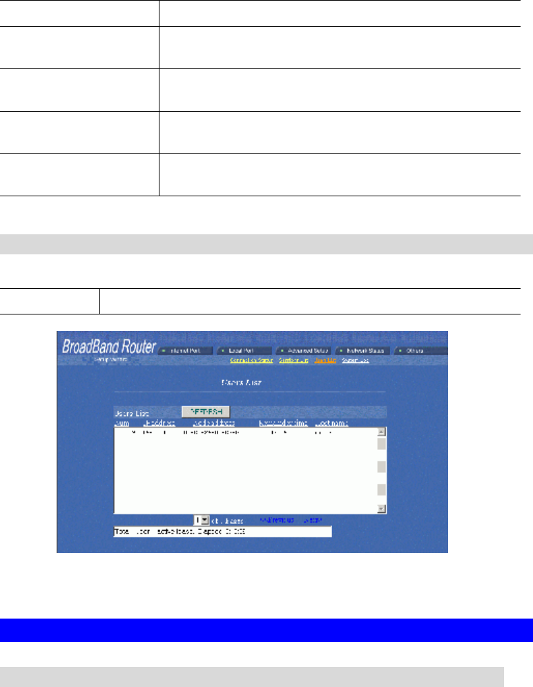
Users List
Displays the current active users.
REFRESH Click this button to refresh the list.
Figure 25
Others
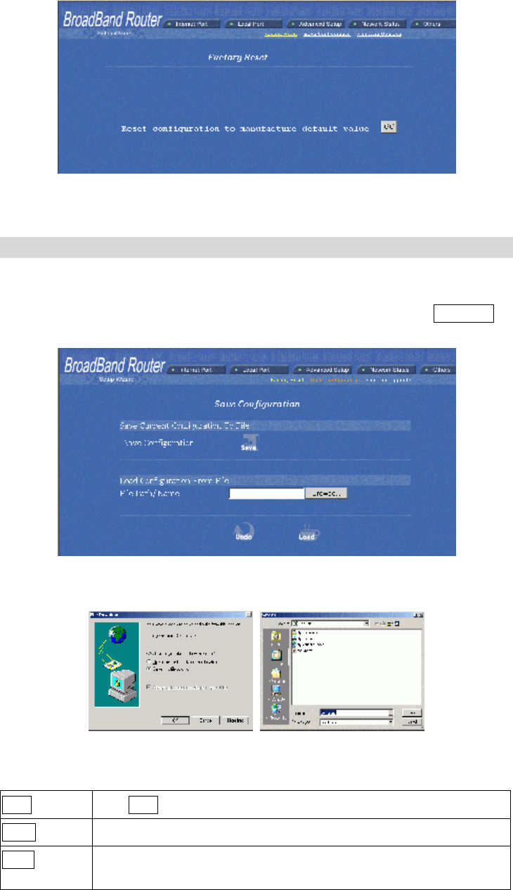
Factory Reset
To reset to factory default setting, click the GO button. Please note that performing the
Factory Reset will erase all previously entered device settings.
27
Figure 26
Save Configuration
This function enables users to always save the current configurations as a file (i.e.
config.sav), so that no re-entry is required when users want to switch between various
configurations. To load configuration from file, enter the file name or click Browse… to
find the file from your computer.
Figure 27
Figure 28 Figure 29
Save Click Save to save the current configuration to file.
Undo Click to clear the input.
Load Click to start loading configuration from file when you are done with
the previous settings.
28
When prompted the upper left screen, select “Save this file to disk”, and the upper right
screen will prompt you a dialog box to enter the file name and the file location. Please
note that the configuration file is in .sav format.
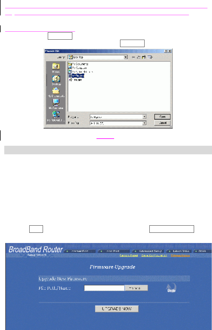
Load Configuration From File
File Path/Name Browse…: If you want to load a configuration file, enter the file name with
the correct path and then click on Load. Or click Browse… to select the file.
Figure 30
Firmware Upgrade
1. Download the latest firmware from your distributor and save the file on the hard
drive.
2. Make sure all computers in the network are off; or connect the HighSpeed Internet
Router directly to the PC that has the new firmware.
3. Start the browser, open the configuration page, click on Others, and click Firm-
ware Upgrade to enter the Firmware Upgrade window. Enter the new firmware’s
path and file name (i.e. C:\FIRMWARE\firmware.bin). Or, click the Browse button,
find and open the firmware file (the browser will display to correct file path).
4. Click Undo to clear all the settings on this page. Or click UPGRADE NOW to
start the upgrade.
Figure 31

29
FCC Warning
Warning: Changes or modifications to this unit not expressly approved by the party
responsible for compliance could void the user authority to operate the equipment.
This device complies with Part 15 of the FCC Rules. Operation is subject to the follow-
ing two conditions: (1) this device may not cause harmful interference, and (2) this
device must accept any interference received, including interference that may cause
undesired operation.
NOTE: This equipment has been tested and found to comply with the limits for a Class B
digital device, pursuant to Part 15 of the FCC Rules. These limits are designed to provide
reasonable protection against harmful interference in a residential installation. This
equipment generates, uses and can radiate radio frequency energy and, if not installed and
used in accordance with the instructions, may cause harmful interference to radio
communications.
However, there is no guarantee that interference will not occur in a particular installation. If
this equipment does cause harmful interference to radio or television reception, which can be
determined by turning the equipment off and on, the user is encouraged to try to correct the
interference by one or more of the following measures:
o Reorient or relocate the receiving antenna.
o Increase the separation between the equipment and receiver.
o Connect the equipment into an outlet on a circuit different from that to
which the receiver is needed.
o Consult the dealer or an experienced radio/TV technician for help.
CAUTION:
1. To comply with FCC RF exposure compliance requirements, a separation distance of
at least 20 cm must be maintained between the antenna of this device and all persons.
2. This Transmitter must not be co-located or operating in conjunction with any other
antenna or transmitter