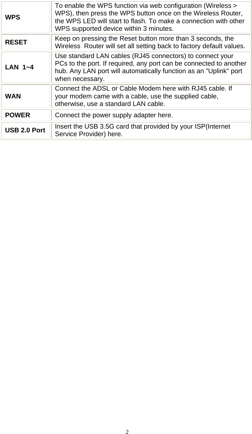
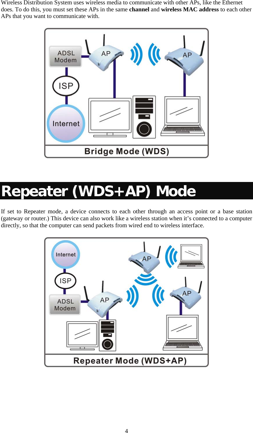
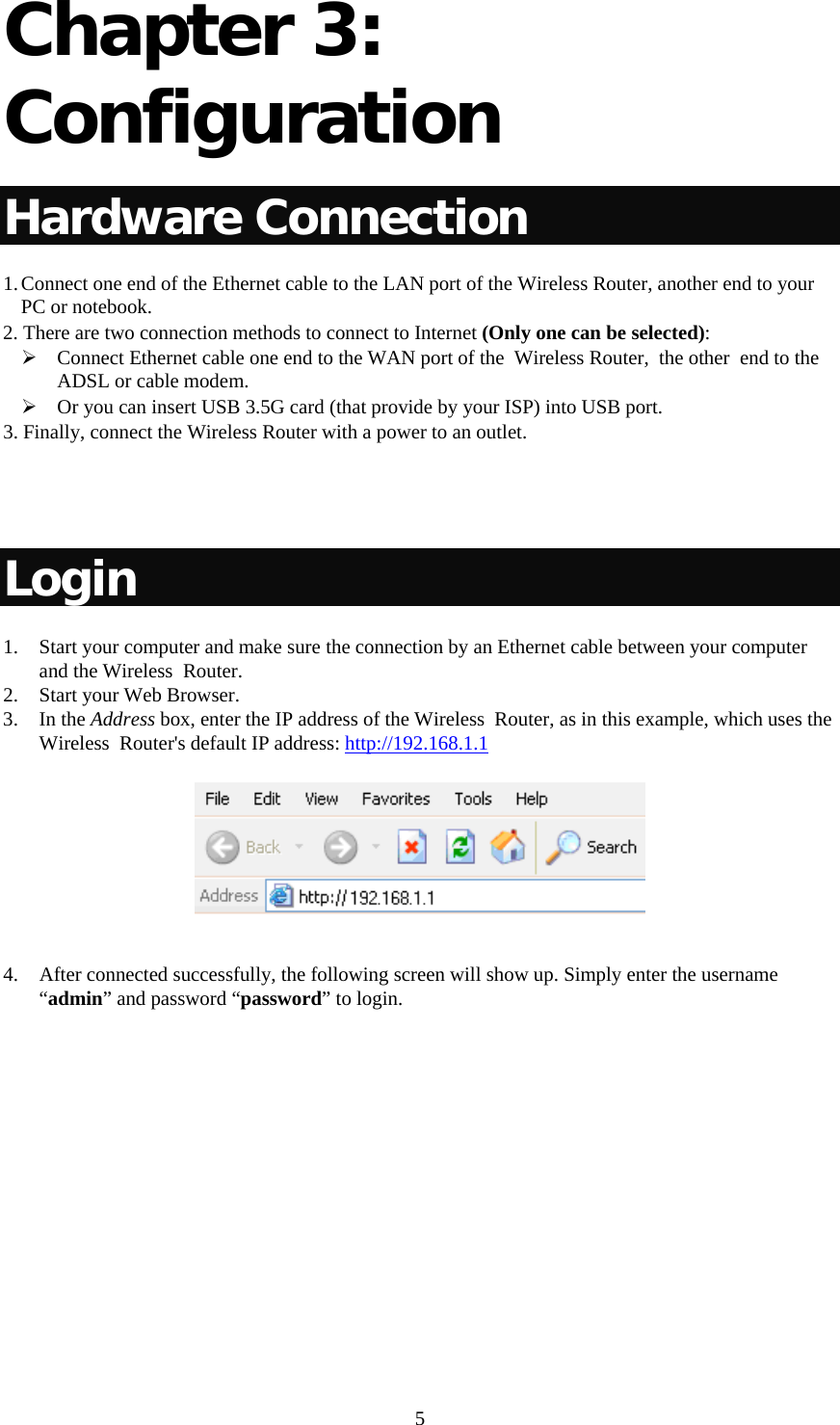
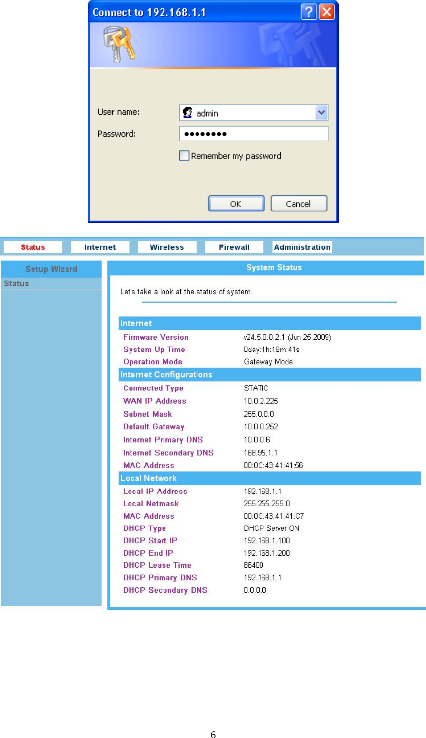
Abocom Systems WR5205G Wireless 11n Giga Router User Manual
Abocom Systems Inc Wireless 11n Giga Router Users Manual
UserManual.wiki
>
Abocom Systems
>
WR5205G User Manual
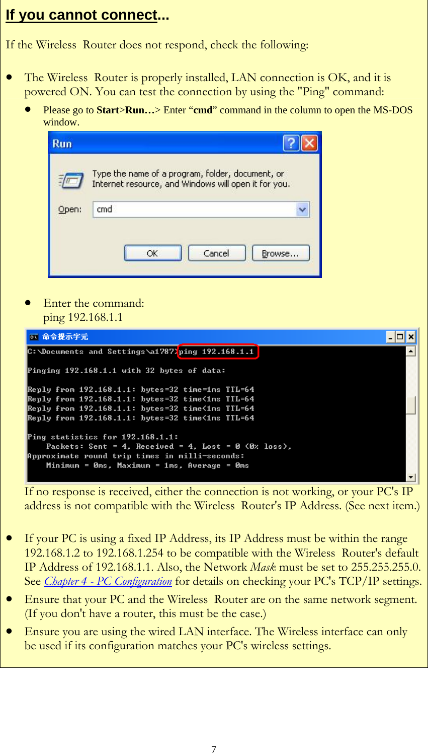
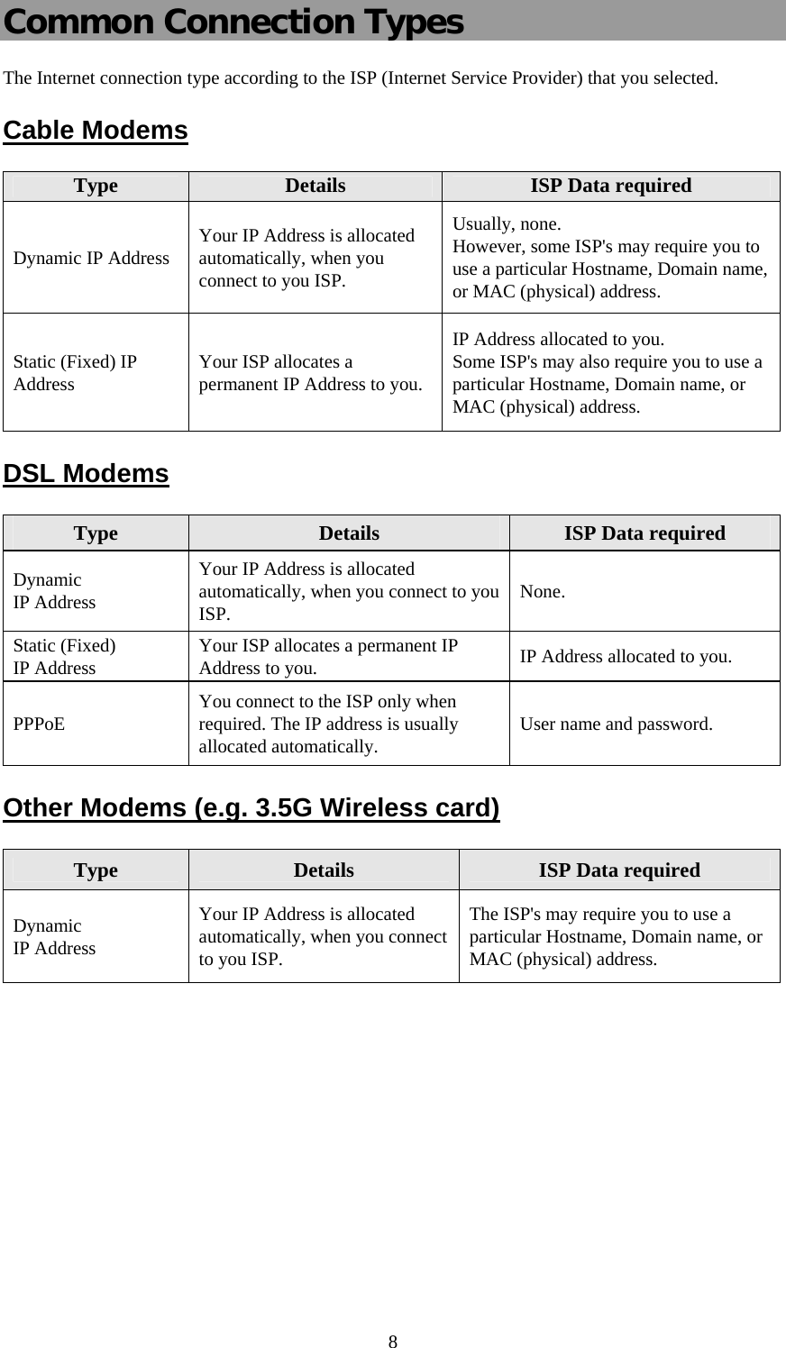
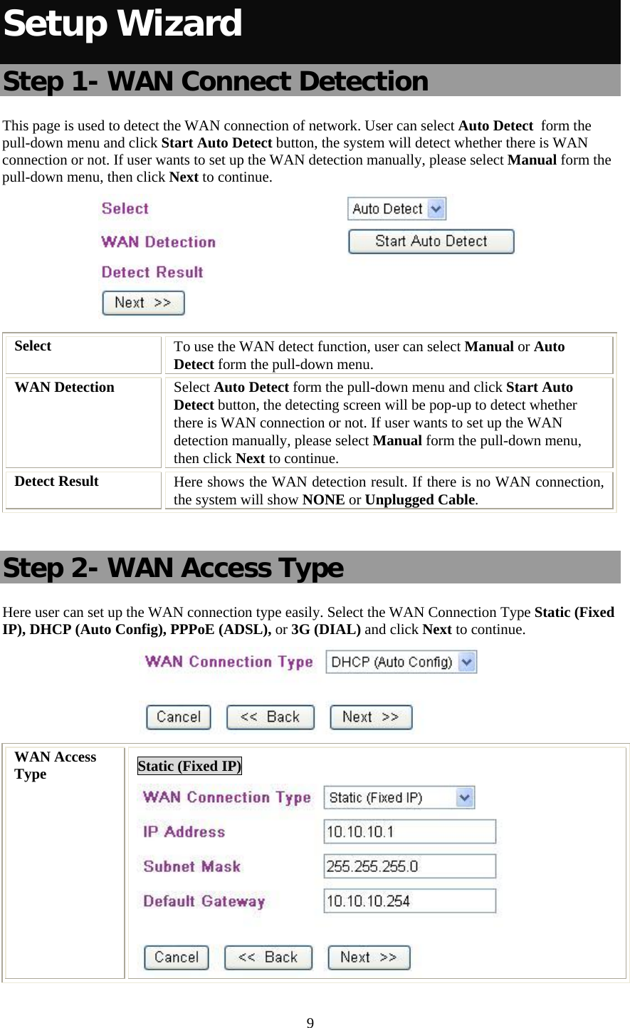
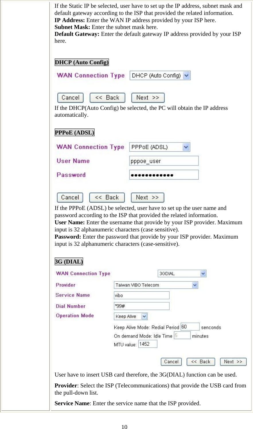
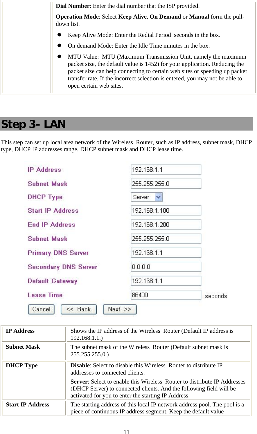
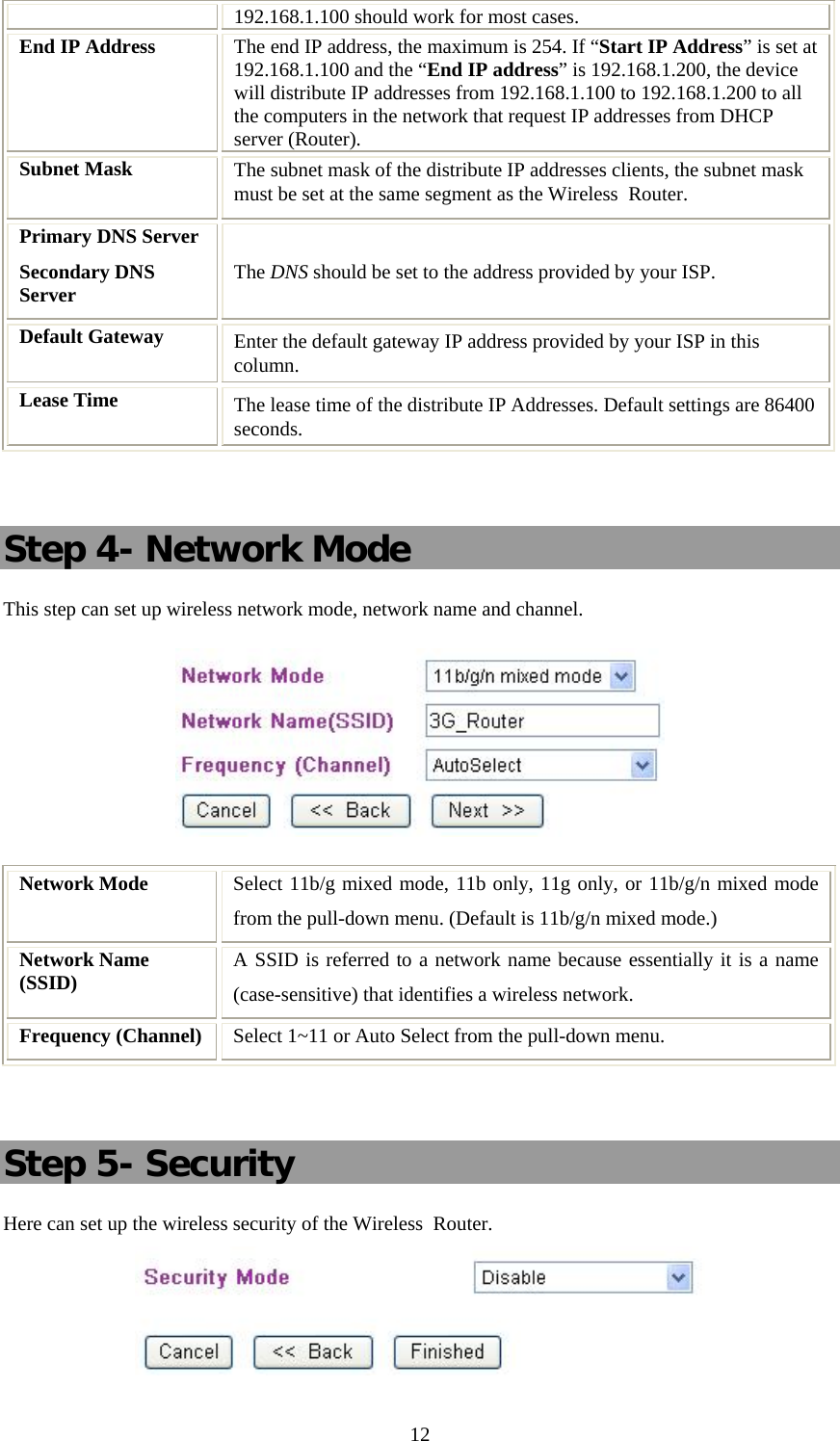
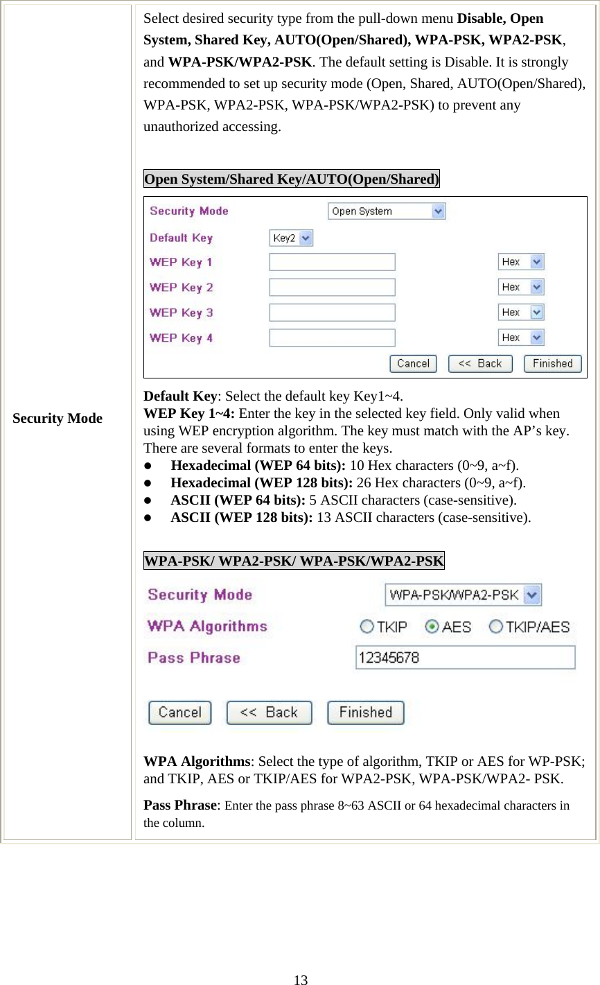
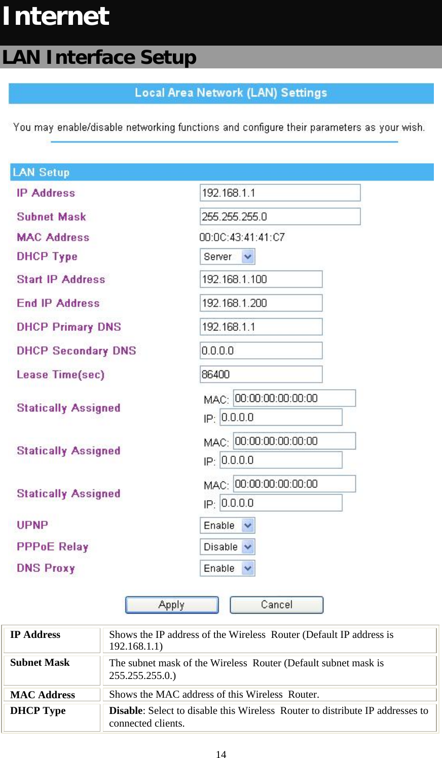
Users Manual
Navigation menu
Upload a User Manual
Namespaces
Wiki Guide
HTML
PDF
Info
Views
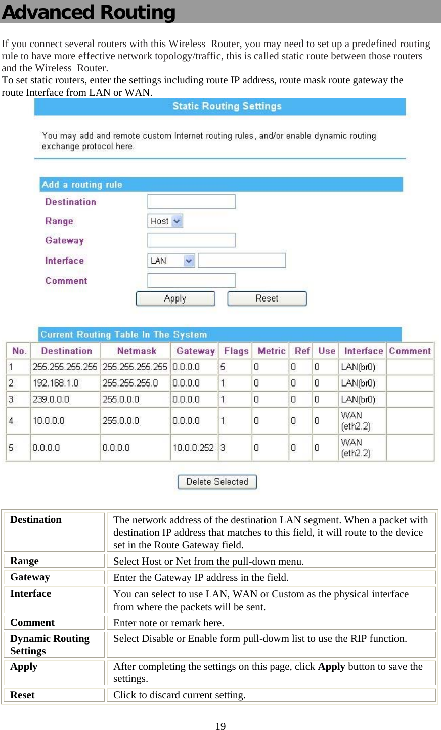
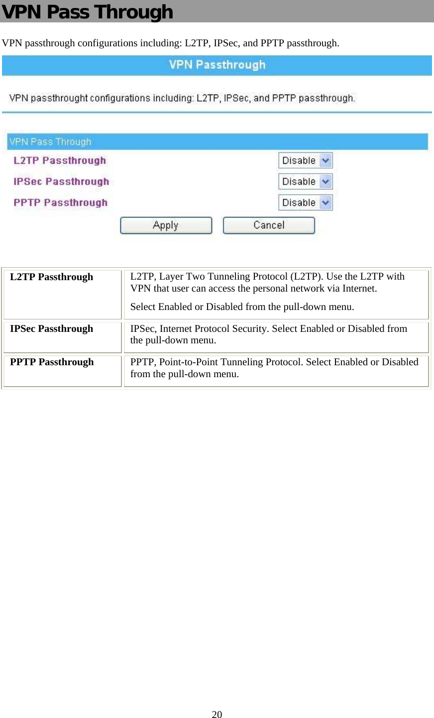
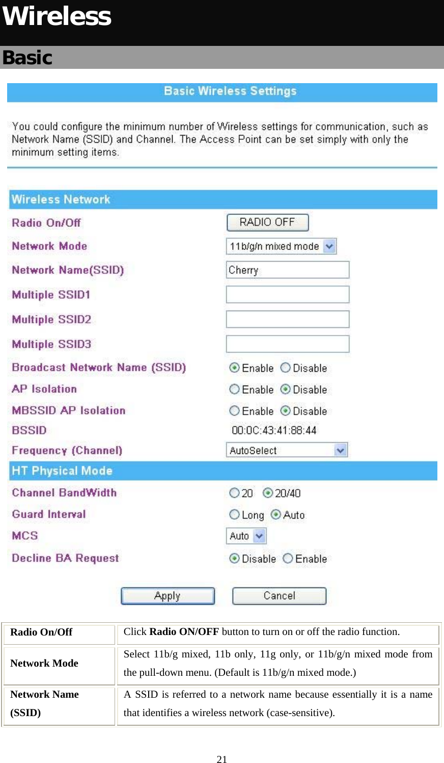
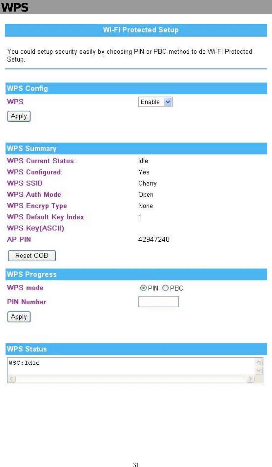
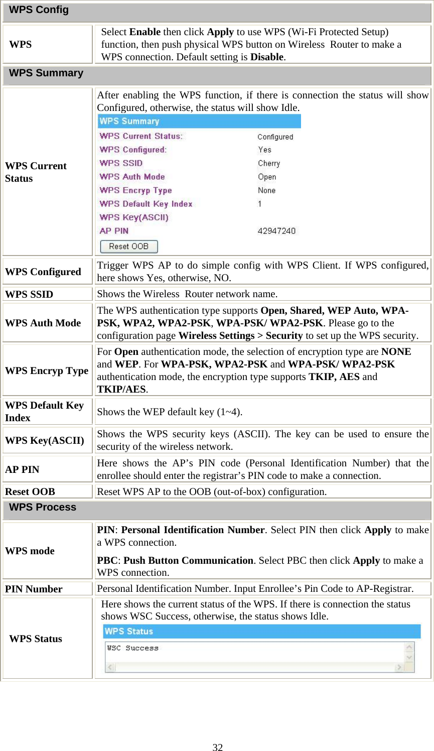
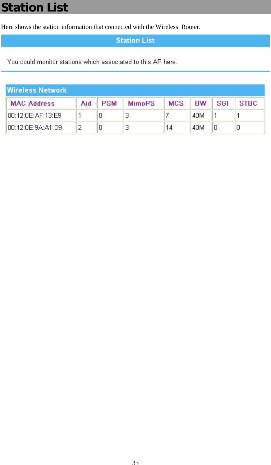
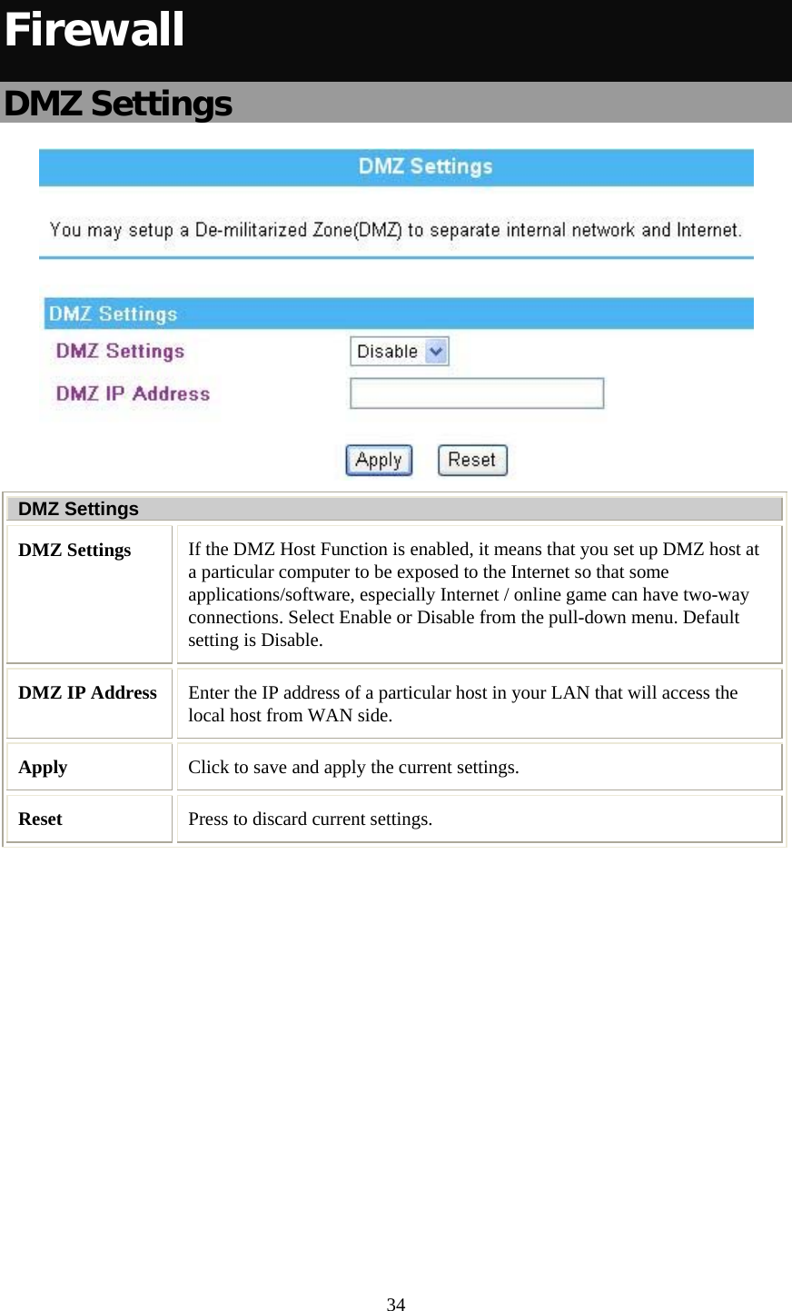
User Manual
Discussion / Help
Navigation