Abocom Systems WR5208 802.11b/g/n Portable 3G Router (Dual USB Function) User Manual WR5208 Manual Eng For FCC only1006
Abocom Systems Inc 802.11b/g/n Portable 3G Router (Dual USB Function) WR5208 Manual Eng For FCC only1006
UserManual.wiki
>
Abocom Systems
>
WR5208 User Manual
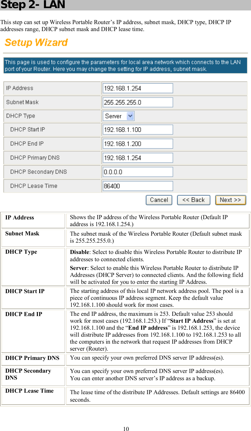
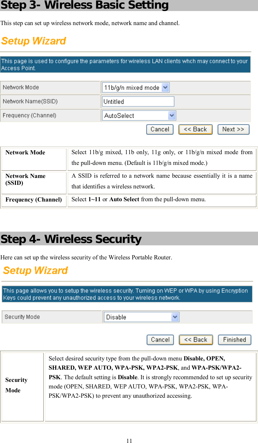
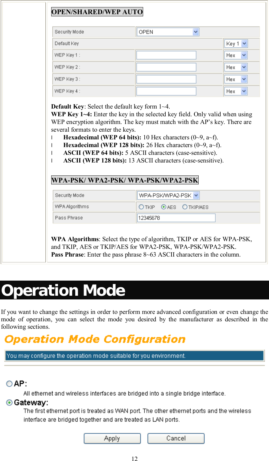
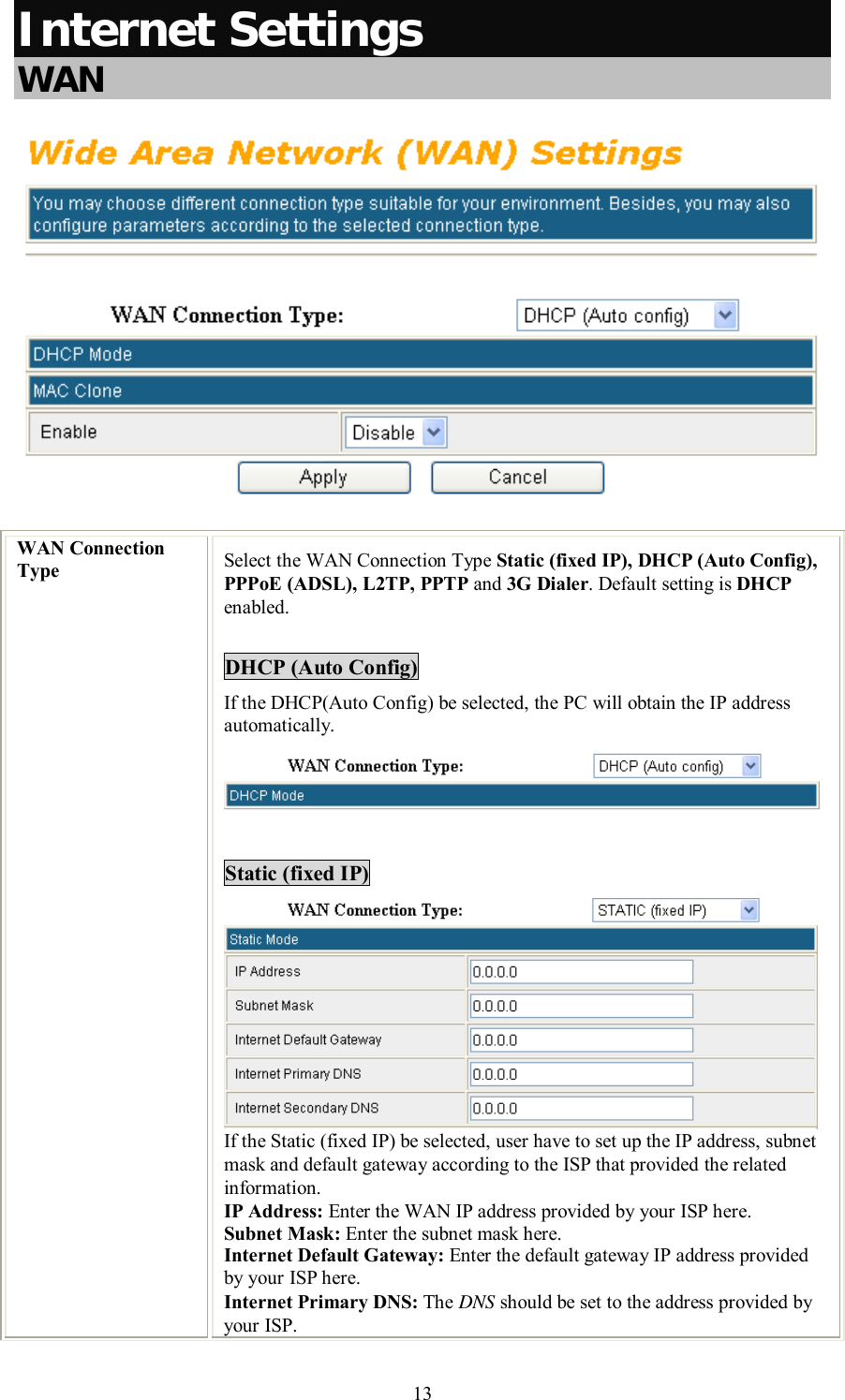
User Manual
Navigation menu
Upload a User Manual
Namespaces
Wiki Guide
HTML
PDF
Info
Views
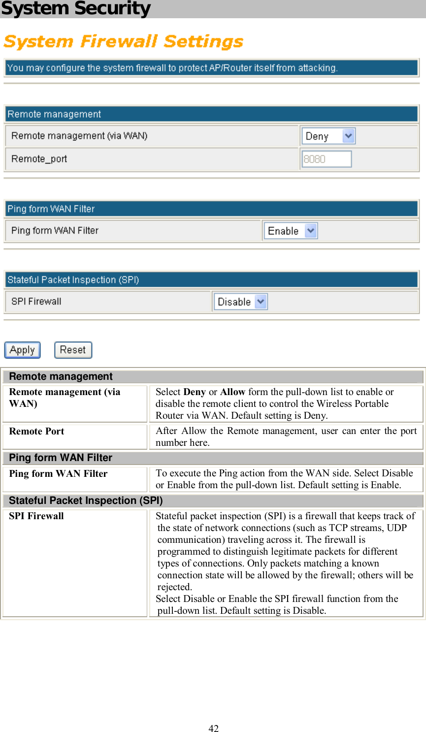
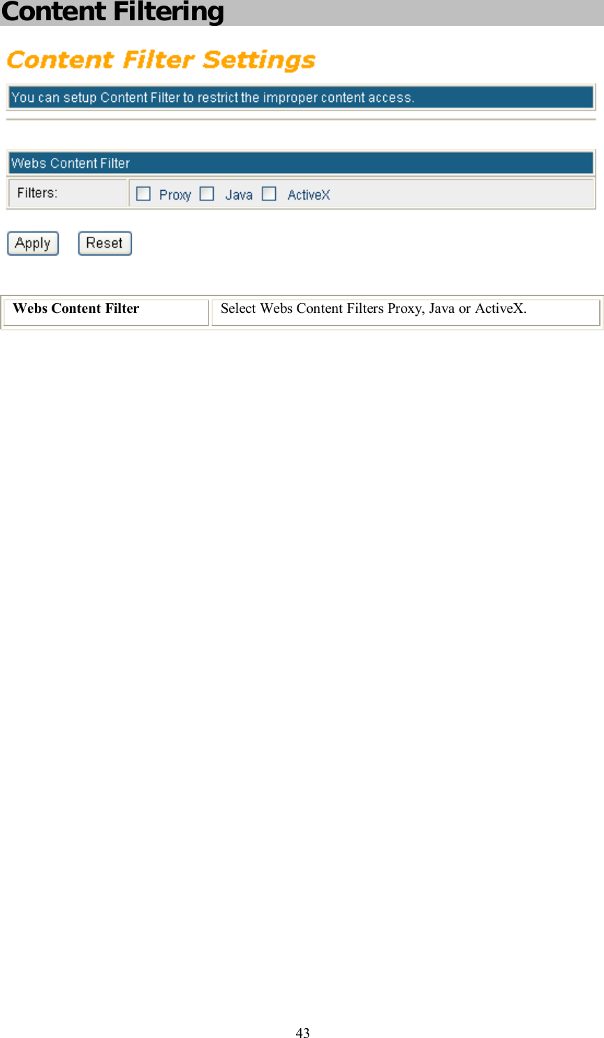
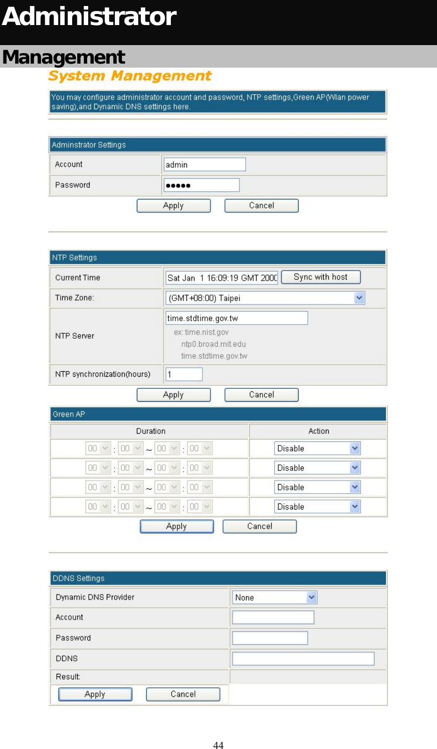
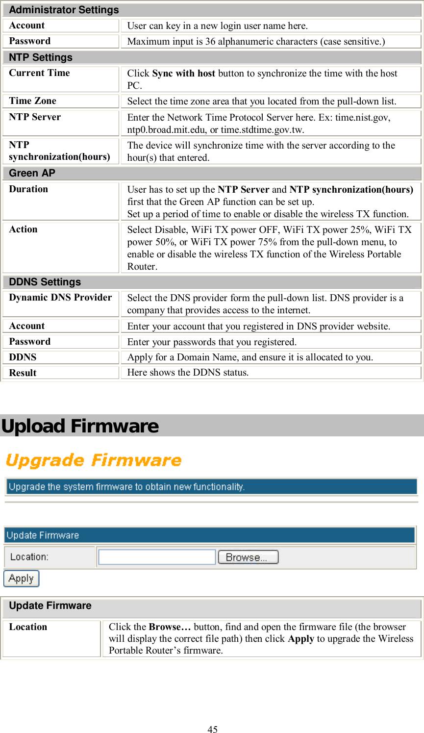
User Manual
Discussion / Help
Navigation