Abocom Systems WUG2690 802.11b/g Wireless LAN USB2.0 module User Manual User s manual ADT revise 0905
Abocom Systems Inc 802.11b/g Wireless LAN USB2.0 module User s manual ADT revise 0905
Manual
802.11b+g Wireless LAN
USB Adapter
WUG2690
User’s Manual
Federal Communication Commission Interference Statement
This equipment has been tested and found to comply with the limits for a Class B
digital device, pursuant to Part 15 of the FCC Rules. These limits are designed
to provide reasonable protection against harmful interference in a residential
installation. This equipment generates, uses and can radiate radio frequency
energy and, if not installed and used in accordance with the instructions, may
cause harmful interference to radio communications. However, there is no
guarantee that interference will not occur in a particular installation. If this
equipment does cause harmful interference to radio or television reception, which
can be determined by turning the equipment off and on, the user is encouraged to
try to correct the interference by one of the following measures:
- Reorient or relocate the receiving antenna.
- Increase the separation between the equipment and receiver.
- Connect the equipment into an outlet on a circuit different from that
to which the receiver is connected.
- Consult the dealer or an experienced radio/TV technician for help.
This device complies with Part 15 of the FCC Rules. Operation is subject to the
following two conditions: (1) This device may not cause harmful interference, and
(2) this device must accept any interference received, including interference that
may cause undesired operation.
FCC Caution: Any changes or modifications not expressly approved by the party
responsible for compliance could void the user's authority to operate this
equipment.
IMPORTANT NOTE:

FCC Radiation Exposure Statement:
This equipment complies with FCC radiation exposure limits set forth for an
uncontrolled environment. This equipment should be installed and operated with
minimum distance 20cm between the radiator & your body.
This transmitter must not be co-located or operating in conjunction with any other
antenna or transmitter.
IEEE 802.11b or 802.11g operation of this product in the U.S.A. is
firmware-limited to channels 1 through 11.
This device is intended only for OEM integrators under the following
conditions:
1) The antenna must be installed such that 20 cm is maintained
between the antenna and users, and
2) The transmitter module may not be co-located with any other
transmitter or antenna,
3) For all products market in US, OEM has to limit the operation
channels in CH1 to CH11 for 2.4G band by supplied firmware
programming tool. OEM shall not supply any tool or info to the end-user
regarding to Regulatory Domain change.
As long as 3 conditions above are met, further transmitter test will not be
required. However, the OEM integrator is still responsible for testing their
end-product for any additional compliance requirements required with this
module installed (for example, digital device emissions, PC peripheral
requirements, etc.).

IMPORTANT NOTE: In the event that these conditions can not be met (for
example certain laptop configurations or co-location with another
transmitter), then the FCC authorization is no longer considered valid and
the FCC ID can not be used on the final product. In these circumstances,
the OEM integrator will be responsible for re-evaluating the end product
(including the transmitter) and obtaining a separate FCC authorization.
End Product Labeling
This transmitter module is authorized only for use in device where the antenna
may be installed such that 20 cm may be maintained between the antenna and
users. The final end product must be labeled in a visible area with the following:
“Contains FCC ID: MQ4WUG2690”.
Manual Information To the End User
The OEM integrator has to be aware not to provide information to the end user
regarding how to install or remove this RF module in the user’s manual of the end
product which integrates this module.
The end user manual shall include all required regulatory information/warning as
show in this manual.
Table of Contents
INTRODUCTION...................................................................................................1
F
EATURES
..............................................................................................................1
SOFTWARE INSTALLATION.............................................................................2
I
NSTALL THE
D
RIVER
&
U
TILITY
............................................................................2
HARDWARE INSTALLATION............................................................................5
NETWORK CONNECTION .................................................................................7
I
N
W
INDOWS
98SE/ME..........................................................................................7
I
N
W
INDOWS
2000/XP .........................................................................................10
IP
A
DDRESS
.........................................................................................................12
Configuration Utility.............................................................................................13
S
TATION
...............................................................................................................15
A
CCESS
P
OINT
......................................................................................................22
Appendix ................................................................................................................28
S
OFT
AP
C
ONFIGURATION
....................................................................................28

-
1 -
INTRODUCTION
The 802.11b+g Wireless LAN USB Adapter is designed for a USB type A port
of a laptop or desktop computer for creating a wireless workstation
.
It is USB 2.0
compliant which connects to any available USB port on a notebook or desktop
computer.
The 802.11b+g Wireless LAN USB Adapter complies with IEEE 802.11g
standard that offers a data rate up to 54Mbps in a wireless LAN environment. It is
backward compliant with IEEE 802.11b specification. The
high-speed wireless
network card can plug into your notebook or desktop PC and accesses to
the LAN or peer-to-peer networking easily without wires or cables.
Whether you’re at your desk or in the boardroom, it allows you to share
printers, files, and other network resources.
Features
Complies with IEEE 802.11g standard for 2.4GHz Wireless LAN
USB 2.0 compliant
USB Plug & Play
Interoperable with existing network infrastructure
Secure information transmission
Freedom to roam while staying connected
Compatible with specialty wireless products and services
Up to 54 Mbps data rate
Low power consumption
Easy to install and configure
-
2 -
SOFTWARE INSTALLATION
Install the Driver & Utility
Caution
!
Do not insert the wireless LAN adapter into your computer until the
procedures in “ Install the Driver& Utility” have been performed.
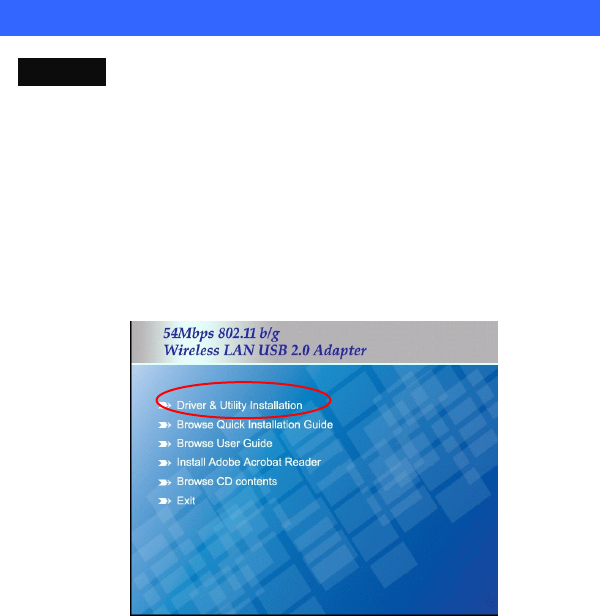
1. Exit all Windows programs. Insert the included CD-ROM into your
computer. The CD-ROM will run automatically.
2. When the Main Menu screen appears, click “ Driver & Utility
Installation” to continue.
-
3 -
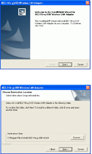
3. When the Welcome screen appears, click Next to continue.
4. The installation program will start running automatically. Follow the
on-screen instruction to proceed.
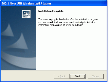
5. Click Finish to complete the software installation.
-
4 -

-
5 -
HARDWARE INSTALLATION
Note: Before you install the device to your computer, make sure you
have installed the driver and utility as described in the previous
section.
Windows 98SE/2000/ME / XP
1. Locate your USB host and insert the USB Adapter.
2. Once the device has been inserted to your computer, Windows will
detect the new hardware.
-
6 -
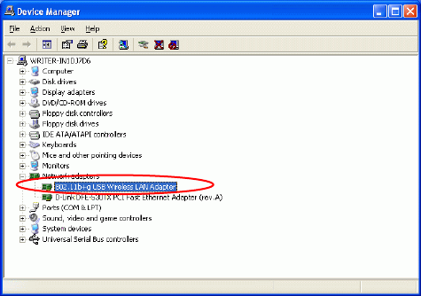
Verify
To verify if the device exists in your computer and is enabled, go to Start
Settings Control Panel System ( Hardware) Device Manager.
Expand the Network Adapters category. If the 802.11b+g USB Wireless LAN
Adapter is listed here, it means that your device is properly installed and enabled.
-
7 -
NETWORK CONNECTION
Once the device driver is well installed, a network setting described in the
following should be also established.
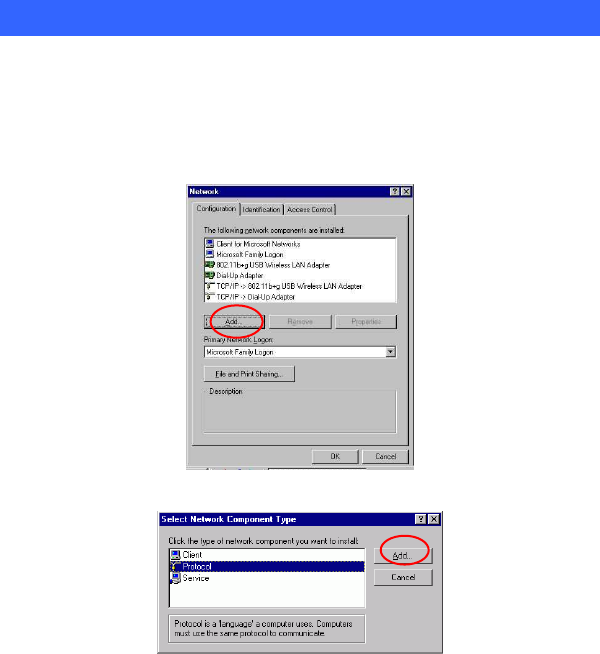
In Windows 98SE/ME
1.
Go to Start
Settings
Control Panel
Network.
2. Make sure that all the required components are installed. If any
components are missing, click on the Add button to add them
in.
-
8 -
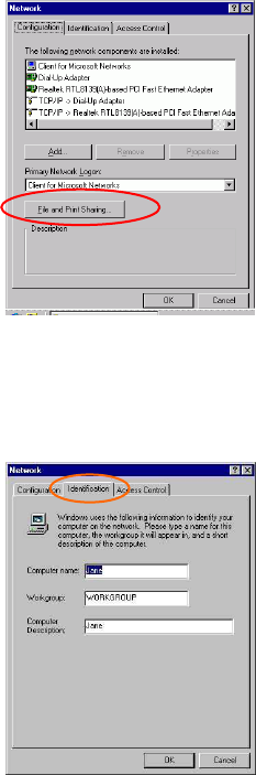
3. For making your computer visible on the network, enable the File
and Print Sharing.
4. Click the Identification tab. Make up a name that is unique from the
other computers' names on the network. Type the name of your
workgroup, which should be the same used by all of the other PCs on
the network.
-
9 -
5. Click the Access Control tab. Make sure that “Share-level access
control” is selected. If connecting to a Netware server, share level
can be set to “User-level access control.”
6. When finished, restart your computer to activate the new device.
-
10 -
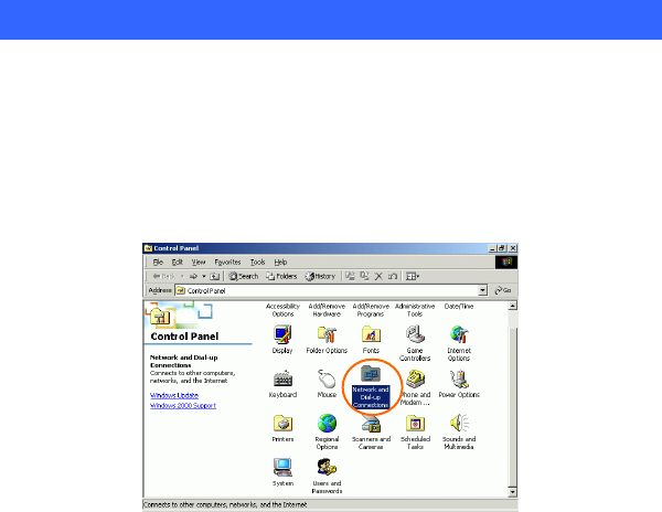
In Windows 2000/XP
1. (In Windows 2000)
Go to Start
Settings
Control Panel
Network and Dial-up
Connections
Local Area Connection
Properties.
(In Windows XP)
Go to Start
Control Panel
Network and Internet Connections
Network Connection
Wireless Network Connection
Properties.
-
11 -
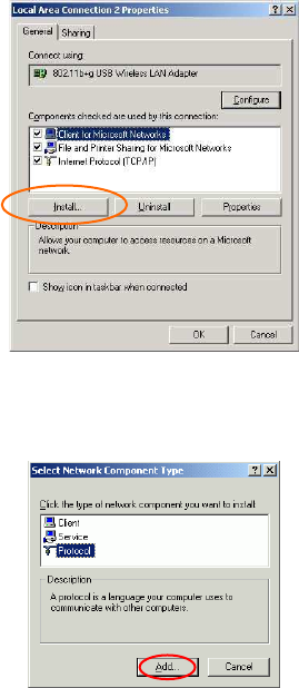
2. Make sure that all the required components are installed.
3. If any components are missing, click on the Install… button to
select the Client/Service/Protocol required. After selecting the
component you need, click Add… to add it in.
4. For making your computer visible on the network, make sure you
have installed File and Printer Sharing for Microsoft Networks.
-
12 -
IP Address
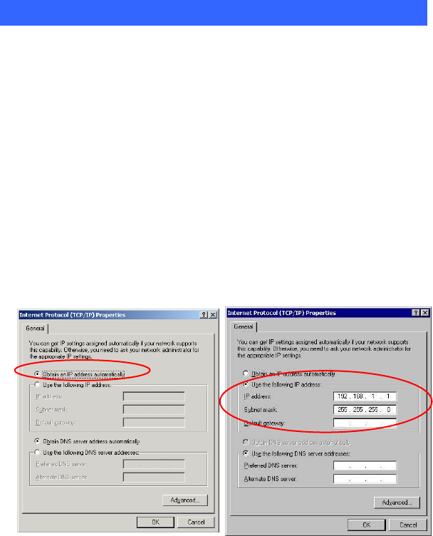
Note: When assigning IP Addresses to the computers on the network, remember
to have the IP address for each computer set on the same subnet mask. If your
Broadband Router use DHCP technology, however, it won’t be necessary for you
to assign Static IP Address for your computer.
1. To configure a dynamic IP address (i.e. if your broadband Router has the DHCP
technology), check the Obtain an IP Address Automatically option.
2. To configure a fixed IP address (if you broadband Router is not DHCP
supported, or when you need to assign a static IP address), check the Use the
following IP address option. Then, enter an IP address into the empty field, for
example, enter 192.168.1.1 in the IP address field, and 255.255.255.0 for the
Subnet Mask.
-
13 -
Configuration Utility
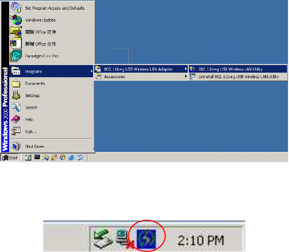
After the Wireless adapter has been successfully installed, users can use the
included Configuration Utility to set their preference.
Go to Start
Program
802.11b+g Wireless LAN
802.11b+g USB
Wireless LAN Utility
For Windows 2000/XP, the Configuration Utility icon will also appear in the
taskbar. You can open the Configuration Utility by clicking the icon.
-
14 -
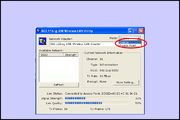
Note: There will be two modes – Station and Access Point for you to
switch, you can select the mode you need from the pull-down menu.
-
15 -
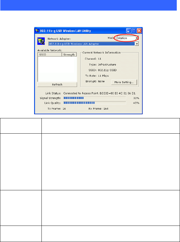
Station
Select Station mode, and you will see the following figure.
Channel Shows the selected channel that is currently in use.
Type
The infrastructure is intended for the connection between
wireless network cards and an Access Point. With the wireless
adapter, you can connect wireless LAN to a wired global
network via an Access Point
The Ad-hoc lets you set a small wireless workgroup easily and
quickly. Equipped with the wireless adapter, you can share
files and printers between each PC and laptop.
SSID
The SSID is the unique name shared among all points in your
wireless network. The name must be identical for all devices
and points attempting to connect to the same network.
It shows the current SSID setting of the Wireless USB
Adapter.
Tx Rate Click the down arrow ▼ to select the Tx Rate from Auto, 1, 2,
5.5, 11, 6, 9, 12, 18, 24, 36, 48, 54 Mbps, you can select up to
-
16 -
54 Mbps.
Encrypt WEP is a data privacy mechanism based on a 64-bit/128-bit
shared key algorithm.
More Setting…
Click the More Setting button to configure, see the following
figure (Refer to the More Setting part on the next page for
more information about this figure):
Link Status Displays the information about the status of the communication
between the Wireless USB Adapter and the Access Point.
Signal Strength Displays the signal strength of the connection between the
Wireless USB Adapter and the Access Point it connects.
Link Quality Displays the link quality of the connection between the
Wireless USB Adapter and the Access Point it connects.
Tx Frame The quantities for the wireless network card transmit.
(Frame: The unit of packet)
-
17 -
Rx Frame The quantities for the wireless network card receive.
(Frame: The unit of packet)
More Setting…
Wireless Mode
This column displays the wirel
ess mode of your wireless adapter
as 2.4GHz (802.11b+g).
Channel The Channel will change automatically according to AP’s setting.
Tx Rate
Click the down arrow ▼ to select the Tx Rate from Auto, 1, 2,
5.5, 11, 6, 9, 12, 18, 24, 36, 48, 54 Mbps, you can select up to 54
Mbps.
SSID
The SSID is the unique name shared among all points in your
wireless network. The name must be identical for all devices and
points attempting to connect to the same network.
Any
You may select to have SSID by choosing any, the
SSID will be
obtained automatically
from whichever Access Point with the
optimal signal for this device. If any
is left unchecked, it means
you will have to enter the SSID manually.
-
18 -
Network Type
The infrastructure is intended for the connection between
wireless network cards and an Access Point. With the wireless
adapter, you can connect wireless LAN to a wired global network
via an Access Point
The Ad-hoc lets you set a small wireless workgroup easily and
quickly. Equipped with the wireless adapter, you can share files
and printers between each PC and laptop.
Encryption
You can only set your Security preference when Change is
selected and then all fields are active for change. To save
settings, press Apply when you are done with the settings. Select
from the pull-down menu, there are four options including
Disable, WEP, TKIP and AES.
Authentication
Mode
You can select the Authentication Mode from the pull-down men,
including Auto, Open System, Shared Key, WPA/WPA2,
WPA PSK and WPA2 PSK.
Encryption
Setting
WEP Encryption Setting WPA Encryption Setting:
::
:
You can only set your Security preference when Change is
selected and then all fields are active for change. To save settings,
press Apply when you are done with the settings.
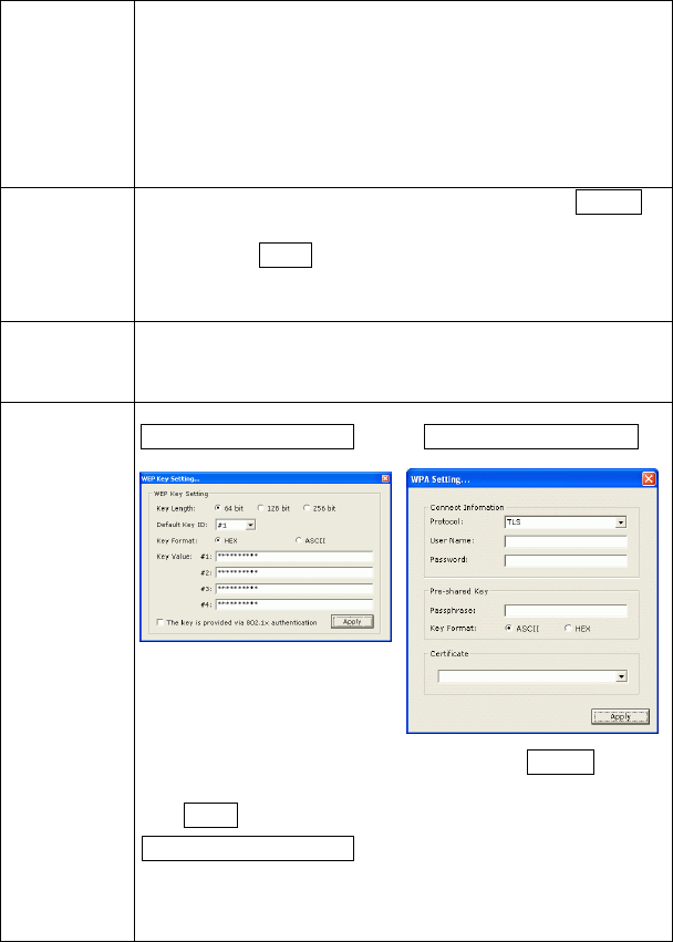
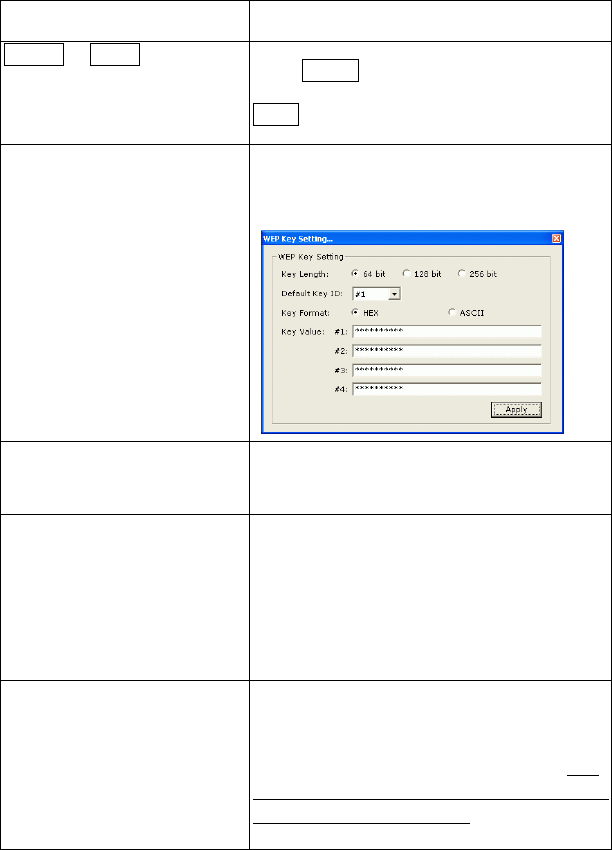
WEP Encryption Setting
Key length :
::
: You may select the key length between 64 (bit),
128 (bit) and 256 (bit).
Default Key ID:
::
:You can set your default key ID at #1~#4.
-
19 -
Key Format :
::
:Select Hexadecimal if you are using hexadecimal
numbers (0-9, or A-F).
Select ASCII if you are using ASCII characters
(case-sensitive).
10 hexadecimal digits or 5 ASCII characters are needed if
64-bit WEP is used; 26 hexadecimal digits or 13 ASCII
characters are needed if 128-bitWEP is used;58 hexadecimal
digits or 29 ASCII characters are needed if 256-bitWEP is
used.
Key Value:
#1~#4 This setting is the configuration key used in accessing
the wireless network via WEP encryption. You can specify up to
4 different keys to encrypt or decrypt wireless data.
□
□□
□ The Key is provided via 802.1x authentication:
::
:
Please query your network manager about the currently used
security protocol, if 802.1x authentication is currently used, then
you can check this item to enable 802.1x security protocol. The
key value will be configured automatically, just click Apply to
take effect.
WPA/WPA2 Encryption Setting
Protocol:
::
:This panel enables you to select an authentication
protocol.
User Name:
::
:Type in the user name assigned to the certificate.
Password:
::
:This panel is available when EAP-TLS is not selected
(either MSCHAP V2 over PEAP is selected with WEP or LEAP
is selected for CCX). This panel enables you to enter a login
name and password or request that the driver prompt for them
when you connect to a network.
Passphrase:
::
:Enter the key that you are sharing with the network
for the WLAN connection.
Key Format:
::
:Select Hex if you are using hexadecimal numbers
(0-9, or A-F).
Select ASCII if you are using ASCII characters.
Certificate:
::
:Please query your network manager about the
certificate, select the same certificate as the certification server.
Profile Name
You may enter a new profile name in this column.
Load You may select already saved file from the "Profile name"
list,
-
20 -
and then press "Load ". The setting status will then be restored.
Save Current
You may save current setting to profile and add one new item in
"Profile name".
Delete Delete the files in the “Profile name”
Advanced
Setting
Click the Advanced Setting button to configure the following
figure (Refer to the Advanced Setting
part on the next page
to see more information about the Advanced Setting):
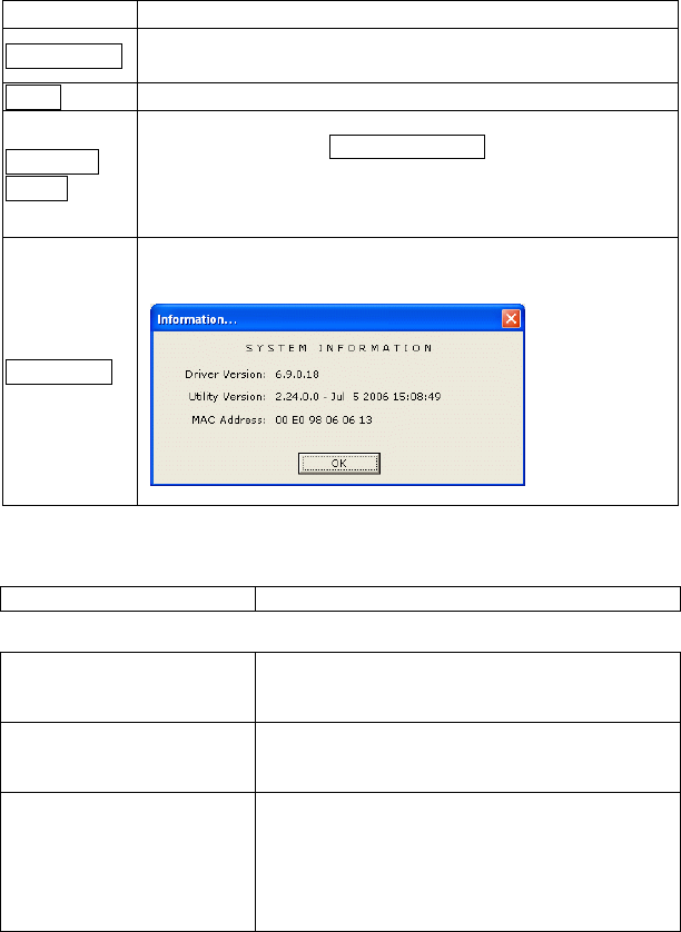
Information
Click the Information button to show the Driver Version, Utility
Version and MAC Address of the system.
User Interface
Language Select English or Traditional Chinese.
Power Consumption Setting
Continuous Access Mode
(CAM)
When this mode is selected, the power supply will
be normally provided even when there is no
throughput.
Maximum Power-Saving
Mode When this mode is selected, this device will stay in
power saving mode even when there is high volume
of throughput.
Fast Power-Saving Mode When this mode is selected, the power mode will
switch between CAM and Maximum Power-Saving
Mode depending on the volume of throughput. The
device driver checks the total bytes (only data
frame) every 4 seconds to decide the power mode.
If the total bytes sent exceed 10k bytes, the device

-
21 -
driver will choose “CAM”. If the total bytes are
less than 10k bytes, however, the device driver will
choose “Maximum Power-Saving Mode”.
Fragmentation Threshold
The mechanism of Fragmentation Threshold is used
to improve the efficiency when high traffic flows
along in the wireless network. If your 802. Wireless
LAN Adapter often transmit large files in wireless
network, you can enter new Fragment Threshold
value to split the packet. The value can be set
from 256 to 2346. The default value is 2346.
RTS/CTS Threshold RTS/CTS Threshold is a mechanism implemented
to prevent the “Hidden Node” problem. If the
“Hidden Node” problem is an issue, users have to
specify the packet size. The RTS/CTS mechanism
will be activated if the data size exceeds the value
you set.. The default value is 2347.
This value should remain at its default setting of
2347. Should you encounter inconsistent data
flow, only minor modifications of this value are
recommended.
-
22 -
Access Point
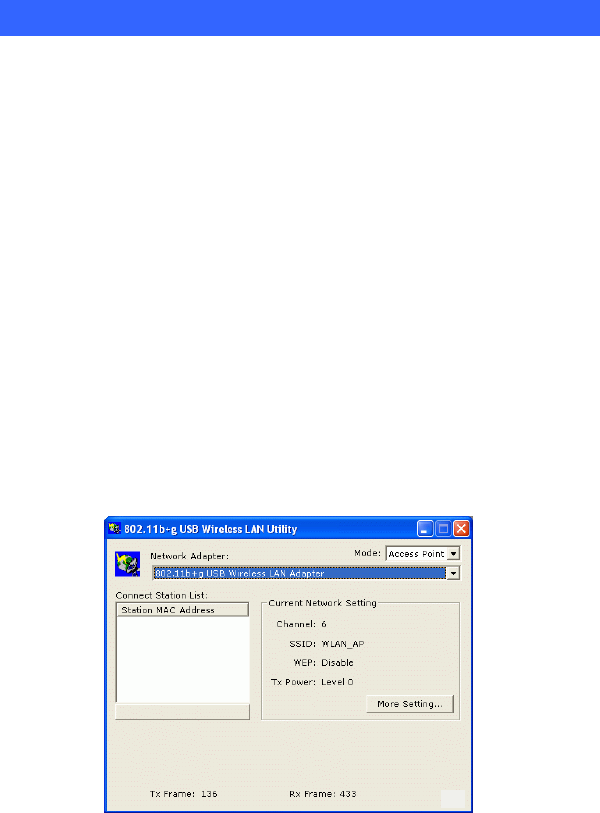
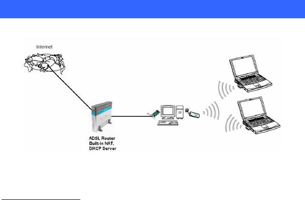
To set your 802.11g Wireless LAN USB Adapter as an Access Point (AP). In
access point mode, the 802.11g Wireless LAN USB Adapter will function as an
access point. This allows you to set up your wireless networks without using a
dedicated AP device. Up to 16 wireless stations can associate to the 802.11g
Wireless LAN USB Adapter.
To the 802.11g Wireless LAN USB Adapter to bridge your wired and wireless
network, the following requirements must be met:
1. The 802.11g Wireless LAN USB Adapter must be installed on a computer
connected to the wired network.
2. Either configure network sharing (refer to the appendix for an example) or
bridge the two interfaces (wireless and wired) on the computer.
3. Set the wireless station’s IP address to be in the same subnet as the computer
in which the 802.11g Wireless LAN USB Adapter is installed. Refer to
Configuring the Wireless Station Computer.
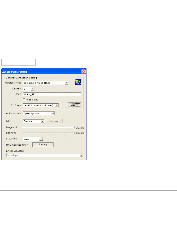
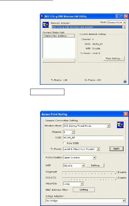
Select the Access Point mode, and you will see the following figure.
-
23 -
Network Adapter
You can select the network adapter from the
pull-down menu, it shows the device itself(
the
802.11g Wireless LAN USB Adapter)
and also
shows the devices supported by the 802.11g
Wireless LAN USB Adapter.
Connection Station List
It shows the stations which are now connecting
to the AP.
Channel Shows the selected channel that is currently i
n
use.
SSID The SSID is the unique name shared among all
points in your wireless network. The name must
be identical for all devices and points attempting
to connect to the same network.
It shows the current SSID setting of the
Wireless USB Adapter.
WEP
The WEP function here has been disabled. If you
want to change to Enabled, click More
Setting… to configure.
Tx Power
The Tx power here is configured as Level 0, to
change the Tx power, click More Setting…
to
configure.
More Setting… Click the More Setting…
button and the
following figure will appear for you to configure
(Refer to the More Setting…
part on the next
page for more information about this figure.)
-
24 -
Tx Frame The quantities for the wireless network card
transmit.
(Frame: The unit of packet)
Rx Frame The quantities for the wireless network card
receive.
(Frame: The unit of packet)
More Setting…
Wireless Mode Select the wireless mode from the pull-
down
menu, there are three modes for you to select,
including 802.11b+g Mixed Mode,
802.11g
only and 802.11b only.
Channel Shows the selected channel that is currently
in
use.
SSID The SSID is the unique name shared among all
points in your wireless network. The name must
be identical for all devices and points attempting
to connect to the same network.
It shows the current SSID setting of the Wireless
USB Adapter.
Tx Power Select the Tx power from the pull-
down menu,
-
25 -
there are four levels including
Level 1, Level 2,
Level 3 (Minimum).
Change or Apply Click Change to set the Gen
eral Connection
Setting. After Completing the setting Click
Apply.
WEP You can select to Enable or Disable
the WEP
function by selecting from the pull-
down men.
Click Setting and the following figure will
appear.
Authentication Mode Select the Au
thentication mode from the
pull-
down menu, there are two modes for you to
choose, Open System and Shared Key.
Fragment The mechanism of Fragmentation Threshold is
used to improve the efficiency when high traffic
flows along in the wireless network. If your 802.
Wireless LAN Adapter often transmit large files
in wireless network, you can enter new Fragment
Threshold value to split the packet. The value
can be set from 256 to 2346. The default value is
2346.
RTS/CTS RTS/CTS Threshold is a mechanism
implemented to prevent the “Hidden Node”
problem. If the “Hidden Node” problem is an
issue, users have to specify the packet size. The
RTS/CTS mechanism will be activated if the data
size exceeds the value you set.. The default value
is 2347.
-
26 -
This value should remain at its default setting of
2347. Should you encounter inconsistent data
flow, only minor modifications of this value are
recommended.
Preamble
A preamble is a signal used in wireless
environment to synchronize the transmitting
timing including Synch
ronization and Start
frame delimiter. Select from the pull-
down menu
to change the Preamble type into Long or Short.
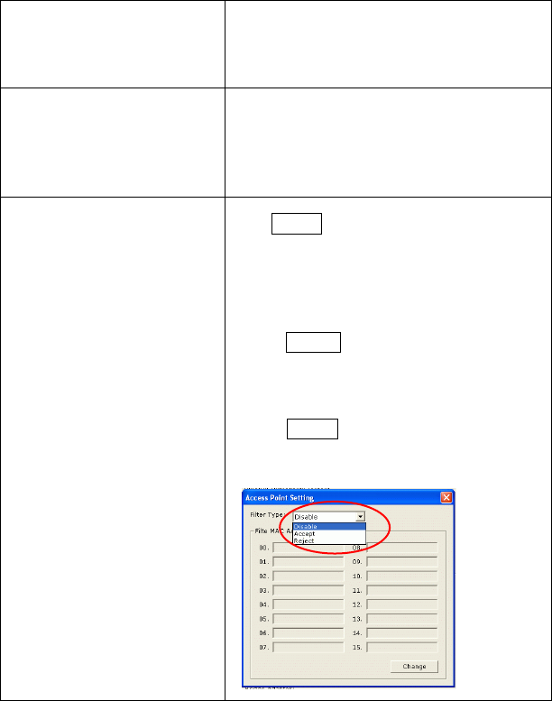
MAC Address Filter Click Setting
and you will see the following
figure. You can select the Filter Type from the
pull-down menu.
Disable:Select to disable the filter function.
Accept:
You can type in 15 MAC addresses by
clicking Change
. If you select Accept, then the
MAC address(es) you type in will be connected
to the AP.
Reject:
You can type in 15 MAC addresses by
clicking Change. If you sele
ct Reject, then the
MAC address(es) you type in will not be
connected to the AP.

-
27 -
Bridge Adapter
The stations will not be allowed to connect to the
internet if you select No bridge.
The stations will be allowed to connect to the
internet if you se
lect the device listed in the
pull-down menu.
-
28 -
Appendix
Soft AP Configuration
Setup Requirement:
To bridge your wired and wireless network using 802.11b+g Wireless LAN USB
Adapter, the following must be met:
1. Install the 802.11b+g Wireless LAN USB Adapter on the LAN-connected
computer.
2. The Soft Access Point should be connected to a network switch, hub or a
Broadband Router. Use a standard Category 5 UTP Ethernet cable with an
RJ-45 connector to connect the Soft Access Point to one of router, hub, or
switch.
3. The computer that you are installing the wireless card into has an Ethernet
connection, and is connected to a LAN with a DHCP server.
-
29 -
SoftAP Configuration:
::
:
1. Select the Access Point mode, and you will see the following figure
2. Click the More Setting… button and the following figure will appear for
you to configure
-
30 -
3. Select the wired Network Adapter that has already installed in the PC
from the pull-down menu.
4. If the network connected to the wired LAN card has a DHCP server, you just
need to configure the wireless station as a DHCP client (select Obtain an IP
address automatically). If the network does not have a DHCP server, you
must assign a fixed IP to the wired PC (select Use the following IP address).