Abon Tech RF88157101 Radio Frequency Identification (RFID) User Manual RFC157 v1 9 eng
Abon-Tech International Corp. Radio Frequency Identification (RFID) RFC157 v1 9 eng
User Manual

RFID Transponder Reader
User Manual
(Model: 88-157-101)
FCC ID: S44RF88157101
DOCUMENT INFORMATION
DOCUMENT ID: UT-RFID-LFRD157-MN01 VERSION NO: 1.9
ISSUED DATE: SEP , 1 , 2004 REVISIED DATE: APR , 14 , 2005

RFID Transponder Reader User Manual Version:1.9
This document is prepared by UNISON Technology Inc. All rights reserved. Page 2 of 31
IMPORTANT NOTES:
This device complies with Part 15 of the FCC Rules. Operation is subject to the
following two conditions:
(1) this device may not cause harmful interference, and
(2) this device must accept any interference received, including interference that may
cause undesired operation.
Any changes or modifications not expressly approved by the party responsible for
compliance could void the authority to operate equipment.
! CAUTION:
01. Read and understand all safety and operating instructions before installing and
operating the device.
02. This instruction is designed for specially trained personnel. This device is NOT
intended for use by the “general population” in an uncontrolled environment.
Installation, operation and error handling the device shall be carried out by specially
trained personnel only.
03.The device cannot be sold retail ,to the general public or by mail order. It must be sold to
dealers.
04. Install in accordance with the manufacturer's instructions only.
05.This product is designed to be mounted and operated in an industrial environment as a
built-in-device only. It is not designed to be used as a stand-alone or a portable device or
in a non-industrial environment, such as a household, vehicle or open-air environment.
06. This manual is designed for specially trained personnel only. This device must be
installed and maintained by the manufacturer or its specially trained representatives.
Intervention or error handling not expressively approved in this manual must be carried
out by the manufacturer’s personnel only. If you are unsure about the qualifications that
are actually required, contact the manufacturer.
z Unqualified interventions may result in personal injury or damage to the device!
07. Do not connect the device to any kind of power supply such as a standard household
power supply. The device should be connected to a power supply of the type described
in these instructions only.
08. When you disconnect a cable, pull on its conductor and not on the cable itself. Keep the
connector evenly aligned to avoid bending any connector pins. When you connect a
cable, ensure that the connector pins are positioned correctly.

RFID Transponder Reader User Manual Version:1.9
This document is prepared by UNISON Technology Inc. All rights reserved. Page 3 of 31
09. Never over bend the antenna cable or expose it to mechanical loads.
10. When replacement parts are required, use the replacement parts specified by the
manufacturer only. Unauthorized substitutions may result in fire, electric shock, or
other hazards.
11. This equipment generates , uses and can radiate radio frequency energy and, if not
installed and used in accordance with the instructions, may cause harmful interference
to radio communications.
12. Never locate the antenna so that it is very close to or touching parts of the body while
transmitting.

RFID Transponder Reader User Manual Version:1.9
This document is prepared by UNISON Technology Inc. All rights reserved. Page 4 of 31
TABLE OF CONTENT
IMPORTANT NOTES AND CAUTION ………………………………………………………. 2
1. INTRODUCTION …………..………………………………………………………………… 6
2. PRODUCT DESCRIPTION …………………………………………………………………. 6
2.1. OVERVIEW ……………………………………………………………………………… 7
2.2. LAYOUT …………………………………………………………………………………. 8
2.3. FUNCTION ………………………………………………………………………………. 11
2.4. SPECIFICATION ………………………………………………………………………… 13
2.5. LOAD PORT INTEGRATION …………………………………………………………... 14
3. SECS OPERATION ………………………………………………………………………….. 15
3.1. INTRODUCTION ………………………………………………………………………... 15
3.2. SECS II MESSAGE ………………………………………………………………………. 15
3.2.1. Message Set ………………………………………………………………………... 15
3.2.2. Message Set Format ……………………………………………………………….. 16
3.3. INTRODUCTION TO SEMI E99 ………………………………………………………... 20
3.3.1. State Model and Transition ………………………………………………………… 21
3.3.2. Services …………………………………………………………………………….. 22
3.3.3. Service Operability ………………………………………………………………… 23
4. ASCII OPERATION …………………………………………………………………………. 23
4.1. HOST COMMAND FORMAT …………………………………………………………… 23
4.2. READER COMMAND FORMAT ……………………………………………………….. 24
5. SETUP …………………………………………………………………………………………. 25
5.1. INSTALLATION PROCEDURE ………………………………………………………… 26
5.2. INITIAL TEST PROCEDURE …………………………………………………………… 26
6. TROUBLE SHOOTING ……………………………………………………………………… 27
6.1. ERROR INDICATOR …………………………………………………………………….. 27
6.1.1. Watch Dog Timer …………………………………………………………………... 27
6.1.2. Read/Write indicator ……………………………………………………………….. 27
6.2. ERROR RECOVERY …………………………………………………………………….. 27
7. ACCESSORIES ……………………………………………………………………………….. 28
7.1. RS232 ……………………………………………………………………………………… 28
7.2. ANTENNA ………………………………………………………………………………... 29
7.3. POWER ADAPTER ………………………………………………………………………. 30
8. SERVICE INFORMATION …………………………………………………………………. 31

RFID Transponder Reader User Manual Version:1.9
This document is prepared by UNISON Technology Inc. All rights reserved. Page 5 of 31
FIGURES
FIGURE 2-1. SYSTEM INTEGRATION ARCHITECTURE………………………………… 7
FIGURE 2-2. READER OPERATION PANEL ………………………………………………. 8
FIGURE 2-3. READER FLANK CONNECTORS …………………………………………… 8
FIGURE 2-4. STICK TYPE ANTENNA ……………………………………………………… 9
FIGURE 2-5. READER APPEARANCE SIZE ………………………………………………. 10
FIGURE 2-6. STICK TYPE ANTENNA ……………………………………………………... 10
FIGURE 2-7. RFID READER CONTROLLER LAYOUT …………………………………... 11
FIGURE 2-8. DIP SWITCH SETTING ……………………………………………………….. 11
FIGURE 2-9. I/O CONNECTOR PIN ASSIGNMENT ………………………………………. 12
FIGURE 3-1. CIDRW STATE MODEL DIAGRAM ………………………………………… 21
FIGURE 7-1. STICK TYPE ANTENNA READOUT DIAGRAM …………………………... 30
TABLES
TABLE 2-1. RFID READER SYSTEM SPECIFICATION ………………………………….. 13
TABLE 2-2. RFID READER STANDARD COMPLIANT …………………………………... 14
TABLE 2-3. KITS P/NS FOR DIFFERENT LOAD PORTS …………………………………. 14
TABLE 3-1. SECS STREAM FUNCTION LIST ……………………………………………... 15
TABLE 3-2. SECS-II RETURN CODE ……………………………………………………….. 20
TABLE 3-3. CIDRW STATE TRANSITIONS ……………………………………………….. 21
TABLE 3-4. COMPLIANT SERVICES LIST ………………………………………………… 22
TABLE 3-5. VALID SERVICES PER STATE ……………………………………………….. 23
TABLE 4-1. ASCII HOST COMMAND FORMAT ………………………………………….. 23
TABLE 4-2. ASCII HOST COMMAND LIST ………………………………………………... 24
TABLE 4-3. ASCII READER COMMAND FORMAT ………………………………………. 24
TABLE 4-4. ASCII READER COMMAND LIST ……………………………………………. 24
TABLE 7-1-1. RS232 CABLE SPEC …………………………………………………………. 28
TABLE 7-1-2. RS232 PIN DEFINITION …………………………………………………….. 28
TABLE 7-2. ANTENNA CABLE SPEC ……………………………………………………… 29
TABLE 7-3. SWITCHING POWER ADAPTOR ……………………………………………... 30

RFID Transponder Reader User Manual Version:1.9
This document is prepared by UNISON Technology Inc. All rights reserved. Page 6 of 31
1. INTRODUCTION
The history of RFID technology could be retraced to early 20th century which is
involving the study of radio wave generation and transmission. The RFID became
reality from 1970’s, many developers、inventors、companies、academic institutions and
Lab are all actively working on RFID. In the past thirty years, the electronic technique
and integrated circuit development were promoted in tenfold speed. It has gradually
driven the RFID technology to commercial and practical applications.
The characteristic of RFID depends on the operating frequency. Unison RFID Reader
works in LF (Low Frequency) range of 134.2 kHz and 125kHz. It uses inductive
coupling and FSK (Frequency Shift Keying) technologies to transmit data between
reader and tag. Non-contact communication reduces the abrasion of tag, and the
read/write do not restrict within line of sight. In addition, the passive tag is energy by
reader, no battery needed during operation. The cost of tag is reduced substantially.
The response time of reader is within hundreds of millisecond, which is dependent on
the data transmission. The reader controller provides standard serial port and Ethernet
port (not support yet) for host connection, most field applications can easily integrate
the reader with those standard ports.
This manual describes the system specification and operation, as well as the procedure
of installation and maintenance. It recommends user to operate reader after reading this
document.
RFID Transponder Reader User Manual Version:1.9
This document is prepared by UNISON Technology Inc. All rights reserved. Page 7 of 31
2. PRODUCT DESCRIPTION
2.1. OVERVIEW
With safe、reliable、low cost requirements, UNISON RFID Reader is specifically designed for
semiconductor and TFT-LCD industry material tracking system by using low frequency RFID
technology. Take semiconductor FAB as an example, the integration of RFID reader and machine
load port can let EAP or MCS to track the cassette/carrier location in the FAB. CIM system can also
take advantage of rich tag information to achieve more efficient automation management.
UNISOSN RFID Reader is composed of reader controller and reader antenna. The RS232 (SECS
I/II) and Ethernet (HSMS) communication ports provide system integration for semiconductor
industry. The tag (transponder) specification is TI® ‘s 134.2kHz low frequency solution, it is the
most popular used RFID tag in 300mm FAB. UNISON RFID Reader is compliant with TI® ‘s LF
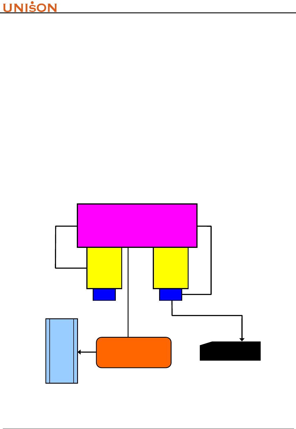
transponder. Following figure illustrate a typical single-wired application with process tool. The
RFID reader controller and antenna are installed in tool load port, and communicate with tool host
by RS232 connection (ASCII or SECS). The lot tracking become more easy and efficient for
automation system.
Figure 2-1. System Integration Architecture
LOAD
PORT
LOAD
PORT
PROCESS TOOL
SECS
STATION
CONTROLLER
H
O
S
T
RFC READER
HSMS
RS232
ASCII / SECS
RFID Transponder Reader User Manual Version:1.9
This document is prepared by UNISON Technology Inc. All rights reserved. Page 8 of 31
2.2. LAYOUT
The housing material of UNISON RFID Reader is made by A.B.S. which is used in electrical device
and will not impact the FAB cleanness. All connectors and switch are designed at controller flank,
and operation panel locate at top side. It make user easily to use it. The appearance and layout are
described as follow.
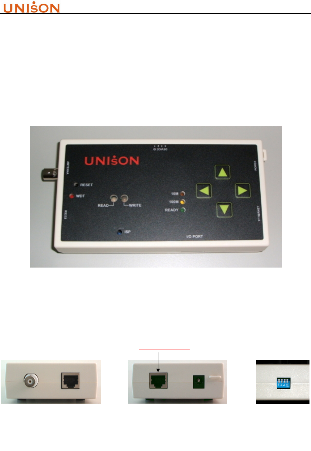
<1>. Operation Panel :
Figure 2-2. Reader operation panel
<2>. Flank connectors :
(not support yet)
Figure 2-3. Reader flank connectors
RFID Transponder Reader User Manual Version:1.9
This document is prepared by UNISON Technology Inc. All rights reserved. Page 9 of 31
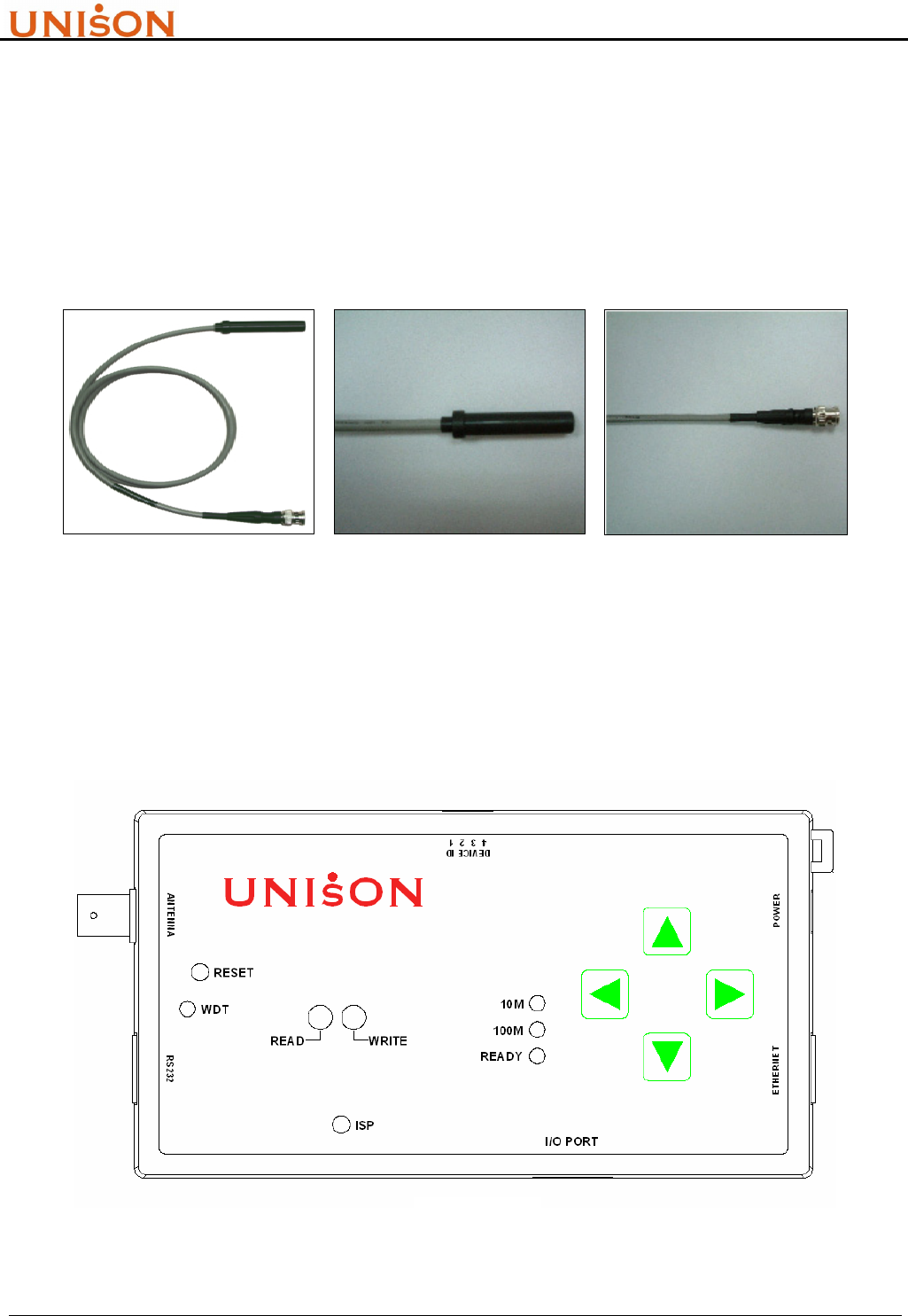
<3>. Antenna :
! Never over bend the antenna cable or expose it to mechanical loads.
The antenna design and RFID reader controller design are physically separated, and can connect
them by common interface. Based on TI® ‘s glass type transponder, UNISON RFID Reader use the
induction coil which is wired and packaged as stick type. Follow pictures show their appearance.
Overall Antenna BNC Connector
Figure 2-4. Stick type antenna
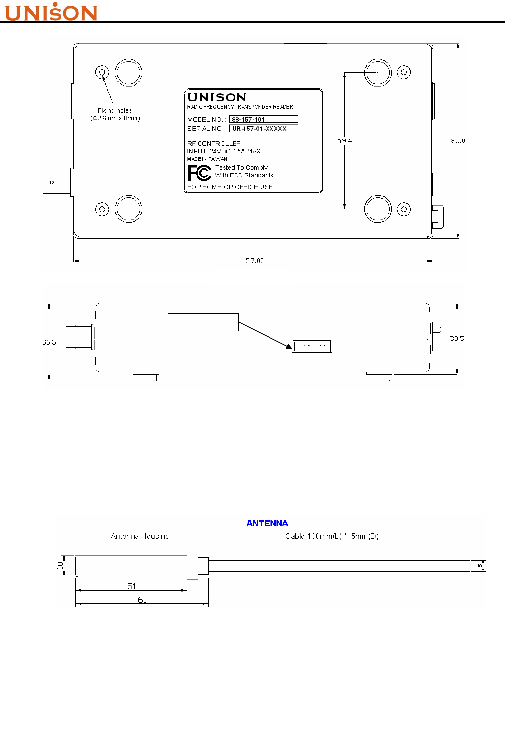
<4>. Size
Standard version of Reader size (product number 88-157-XXX) is listed below,
TOP VIEW
RFID Transponder Reader User Manual Version:1.9
This document is prepared by UNISON Technology Inc. All rights reserved. Page 10 of 31
Figure 2-5. Reader appearance size
Antenna size
Figure 2-6. Stick type antenna dimension
The description of UNISION RFID Reader functions are referred to section 2.3.
SIDE VIEW
not support yet
BAC
K
VIEW
RFID Transponder Reader User Manual Version:1.9
This document is prepared by UNISON Technology Inc. All rights reserved. Page 11 of 31
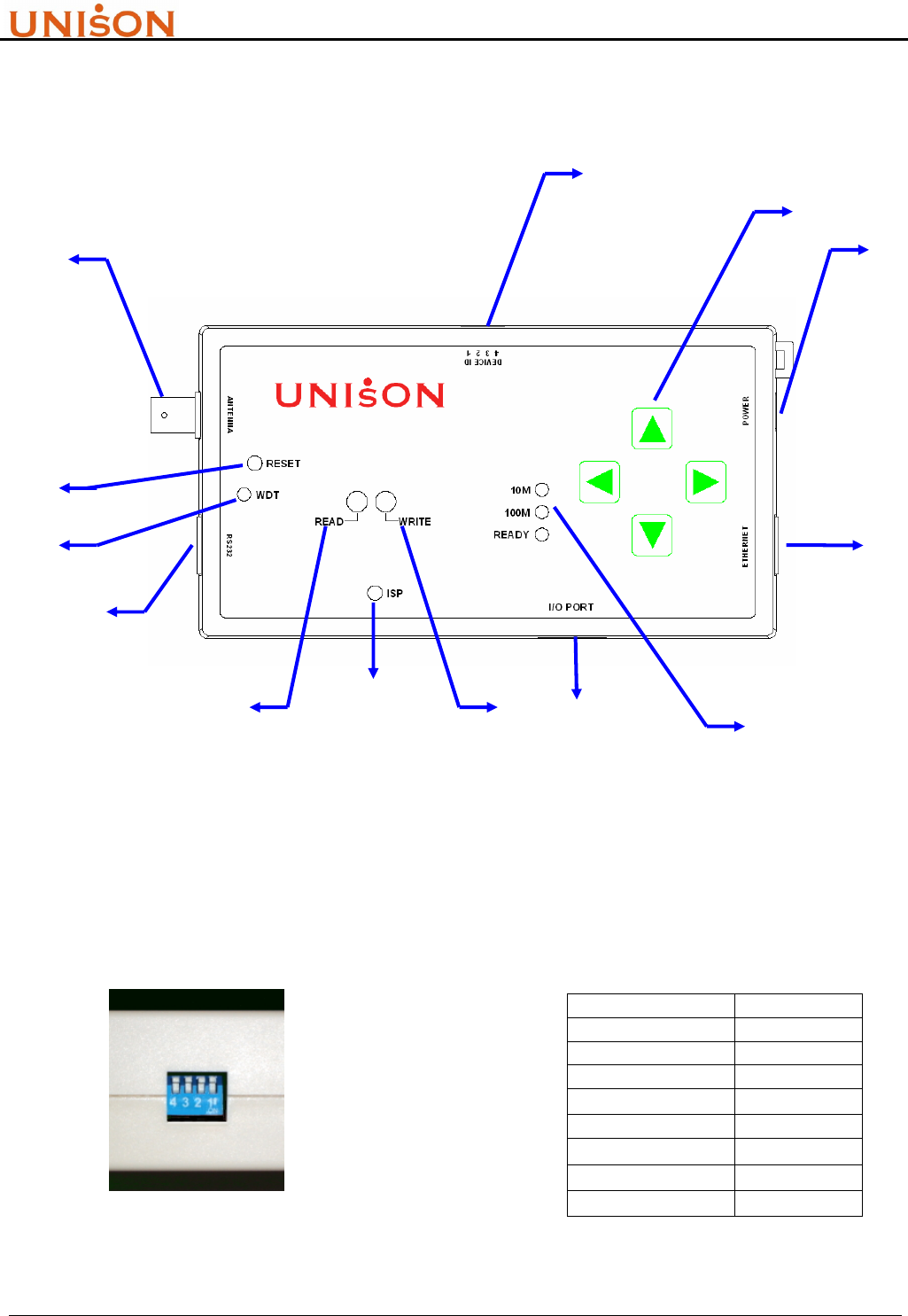
2.3. FUNCTION
Figure 2-7 indicate all the functions on the RFID reader controller. This section will describe those
functions in details.
Figure 2-7. RFID reader controller layout
1. DIP Switch
To set RFID reader controller‘ s device ID. Host controller can identify the connected readers
by this ID number. The range is from 0 ~ 7, and totally eight devices are available in one host
link. After set the DIP switch, it needs to reset reader controller to take effect. The DIP switch
and device ID mapping is shown in Fig 2-8.
DIP Switch Device ID
All Down 0
1 up 1
2 up 2
1、2 up 3
3 up 4
1、3 up 5
2、3 up 6
1、2、3 up 7
Figure 2-8. DIP switch setting
(2)
(3)
(4)
(5)
(7) (9)
(10)
(13)
(8) (6)
(1)
(12)
(11)
RFID Transponder Reader User Manual Version:1.9
This document is prepared by UNISON Technology Inc. All rights reserved. Page 12 of 31
2. Select Button
A. Reserve for selection input when connecting external display device such as LCD.
B. Push UP and DOWN buttons simultaneously, system will run internal test once, and will
write string “0000000000000000” (only for multi page tag) to tag MID if successfully.
3. Power Input
24V , 0.5A DC input
4. HSMS Interface Connector (not apply to 88-157-101)
Reserve for Semi standard HSMS interface
5. Ethernet Indicator (not apply to 88-157-101)
Ethernet speed and status indicators. “10M/100M” indicates HSMS port current speed, and
“READY” indicates the HSMS port is ready or not.
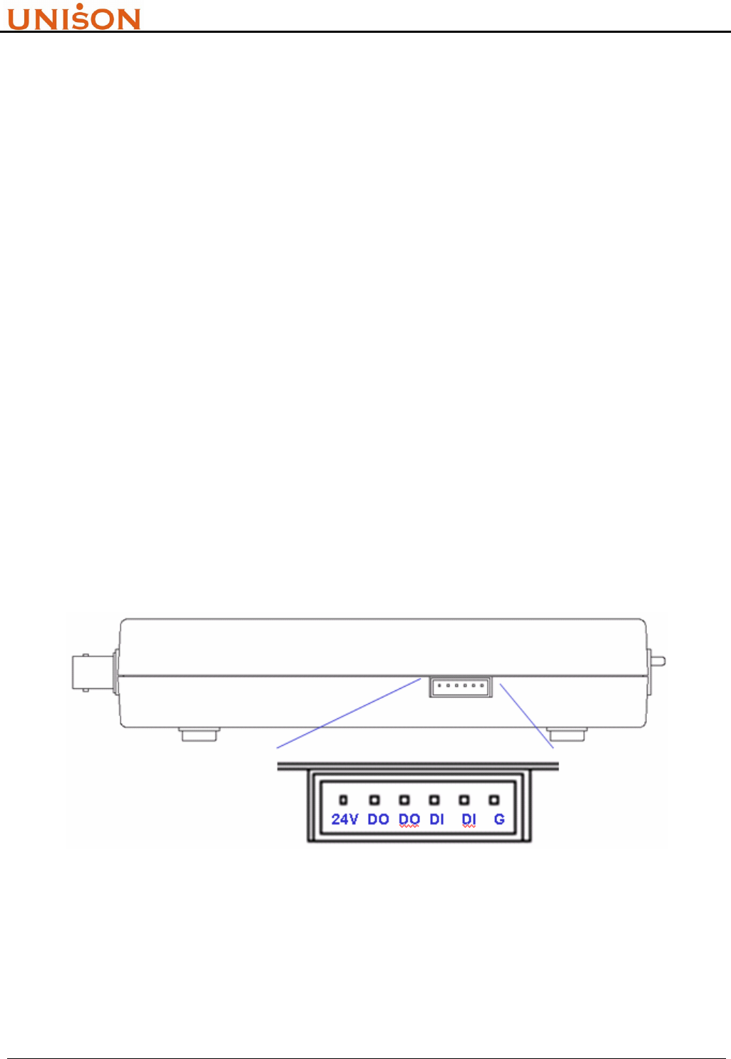
6. I/O Port (not apply to 88-157-101)
There are four input/output contact points can be used to integrate with external device. It
provides user the additional control functions such as external trigger. The pin assignment is
defined as in Figure 2-9.
Figure 2-9. I/O connector pin assignment (not support yet)
7. WRITE Indicator
Used to indicate the executing command is “write”. When command start to execute, the light
of indicator turn to green. Green color will be turned off if the command is executed

RFID Transponder Reader User Manual Version:1.9
This document is prepared by UNISON Technology Inc. All rights reserved. Page 13 of 31
successfully. Otherwise, if the command execution is failed, the light of indicator will turn to
red, it will not turn off until next command is executed.
8. ISP Button
In System Programming function button. Technician can update firmware through RS232 port
by enabling this button.
9. READ Indicator
Used to indicate the executing command is “read”. When command start to execute, the light
of indicator turn to green. Green color will be turned off if the command is executed
successfully. Otherwise, if the command execution is failed, the light of indicator will turn to
red, it will not turn off until next command is executed.
10. RS232 Interface Connector
Serial port interface to support Semi standard SECS I/II protocol.
11. Watch Dog Timer Indicator
Used to indicate the system health. The red light will be flashing after successfully
initialization.
12. RESET Button
Reset reader controller CPU. Usually used to restart controller after upgrade firmware.
13. Antenna Connector
Standard BNC connector to connect antenna and reader.
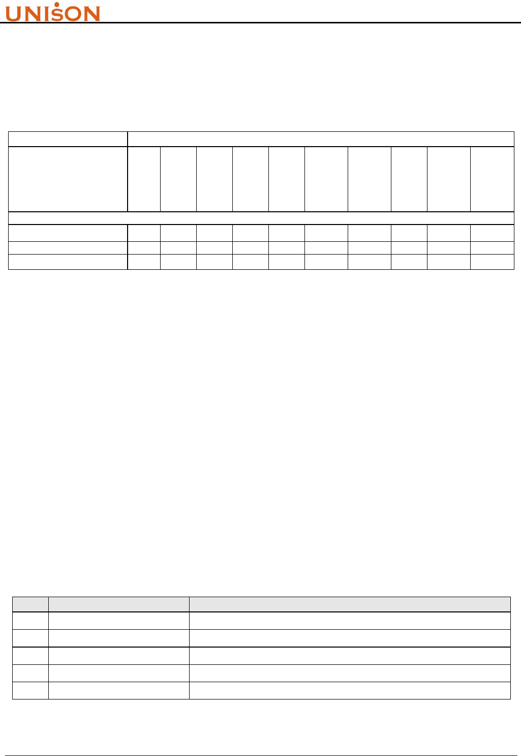
2.4. SPECIFICATION
UNISON RFID Reader system specification and compliant standard are listed in Table 2-1 and
Table 2-2.
Table 2-1. RFID Reader System Specification
Item Name Specification
1 RF working frequency 134.2 KHz
2 Tag chip provider TI®
Read 10mm ~ 85mm
3 Detect Range Write 10mm ~ 65mm
MID 16 bytes / 2 pages(MPT) , 8 bytes / 1 page(SPT)
4 Memory size DATA 120 bytes / 15 pages(MPT)

RFID Transponder Reader User Manual Version:1.9
This document is prepared by UNISON Technology Inc. All rights reserved. Page 14 of 31
MID max. bytes : Read 0.15 sec ; Write 0.68 sec
5 Working duration time DATA max. bytes : Read 2 sec ; Write 6 sec
6 External power 120/240V 50/60 Hz DC 24V 0.5A
7 Working Humidity 20% ~ 80%RH
8 Working Temperature 0℃ ~ +55℃ / 32℉ ~ 131℉
9 Communication SECS I/II、ASCII、HSMS(in roadmap)
10 Serial port baud rate 9600 , N , 8 , 1
11 Antenna Connector Type BNC male
12 RS232、Ethernet Connector RJ45
13 RS232 host Connector 9 pin female
14 I/O connector 0.98” pitch, 6 pins male, disconnectable
15 Weight (without antenna) 230g
16 Reader size 157mm x 85mm x 33.5mm (L x W x H)
Table 2-2. RFID Reader Standard Compliant
Item Name Description
1 SEMI E15.1 Specification for Tool Load Port
2 SEMI E99 , E99.1 Specification for Carrier ID Reader/Writer
2.5. LOAD PORT INTEGRATION
The most common application of RFID reader in Semiconductor and TFT-LCD industry is to
integrate with equipment load port to track cassette/FOUP move-in and move-out. Table 2-3 lists
the mapping for RFID reader and load port vendor.
Table 2-3. Kits P/Ns for different Load Ports
Description Kit N/O
TDK® Front Load UT-0010-01
ASYST® Front Load (S2,S3) UT-0020-01
ASYST® IsoPort UT-0020-02
Brooks® Load Port UT-0030-01
AMAT® Load Port UT-0040-01
TEL® Load Port UT-0050-01
Kaijo® Load Port UT0060-01
8” SMIF FAB (SMIF I/O) UT-0080-01
8” Bare cassette UT-0090-01

RFID Transponder Reader User Manual Version:1.9
This document is prepared by UNISON Technology Inc. All rights reserved. Page 15 of 31
3. SECS OPERATION
3.1. INTRODUCTION
! This manual is designed for specially trained personnel only. This device must be installed and
maintained by the manufacturer or its specially trained representatives.
! Unqualified interventions may result in personal injury or damage to the device!
SEMI Equipment Communications Standard is a coordinated pair of standards for the
semiconductor industry that defines a serial communications interface between equipment and a
host. SECS-I (SEMI E4-91) defines the transfer of binary messages through an RS-232 link
communication. SECS-II (SEMI E5-95) is designed to use SECS-I, and it defines the high level data
structures of message.
SECS II message are organized into “stream” and “function”. “Stream” represents the category of
activities, it is identified by a 7 bits code (0~127). “Function” represents the use of that activity, it is
identified as an 8 bits code (0~255). SECS II message data structures are composed of entities called
items and list of items, those data will be processed by SECS driver and sent between equipment
and host. For application user, the message format and definition are most important, they will be
described in section 3.2.
SEMI E99 is another standard to define the usage of RFID reader in FABs. All related carrier ID
products must be compliant to this standard to avoid integration problem. The E99 compliance topic
is described in section 3.3.
Some specific machine or equipment does not support SECS protocol. This situation can be solved
alternatively to use ASCII command string by RS232 serial port. Chapter 4 will describe the ASCII
command mode communication.
3.2. SECS II MESSAGE
3.2.1. Message Set
The SECS communication protocol between RFID reader and equipment host is defined in SEMI
E99. There are three Streams and fifteen common used Functions. Table 3-1 summaries those
streams and functions.
Table 3-1. SECS Stream Function list
Function
Stream Primary Secondary Direction Description
1 1 2
H → R Are you there

RFID Transponder Reader User Manual Version:1.9
This document is prepared by UNISON Technology Inc. All rights reserved. Page 16 of 31
1 2
H → R Query system state
3 4
H → R Set system state
5 6
H → R Read data
7 8
H → R Write data
9 10
H → R Read MID
11 12
H → R Write MID
13 14
H → R Change State
73 -
H → R Initialize system
18
71 -
H ← R Power On status
1 -
H ← R unrecognized device ID
3 -
H ← R unrecognized stream
5 -
H ← R unrecognized function
7
H ← R SECS format error
9
9 -
H ← R transaction time out
3.2.2. Message Set Format
According to the definition of Stream and Function, the SECS II message format samples are list as
follow:
1. S1F1 Are You There
Header only
2. S1F2 Are You There reply
<L2
< A[20] > //model no.
< A[8] > //software version
>
3. S18F1 Query System State
<L1
<A[00~07]> //Device ID
>
4. S18F2 Query System State reply
< L3
< A [00~07]> //DeviceID
< A [XX] > //Return code
<L4
< A [XX] > //PM information
< A [1~8] > //Alarm status
< A [XXXX] > //Operation state
< A [XXXX] > //Head status
>
>

RFID Transponder Reader User Manual Version:1.9
This document is prepared by UNISON Technology Inc. All rights reserved. Page 17 of 31
5. S18F3 Set System State
<L2
<A[00~07]> //Device ID
<A[00~01]> //setting value
>
6. S18F4 Set System State reply
< L3
< A [0~7]> //DeviceID
< A [XX] > //Return code
<L4
< A [XX] > //PM information
< A [1~8] > //Alarm status
< A [XXXX] > //Operation state
< A [XXXX] > //Head status
>
>
7. S18F5 Read Data
<L3
< A[00~07] > // DeviceID
< A [0~119] > // Start offset address
< A [ReadNo.] > // Number of bytes to read
>
8. S18F6 Read Data reply
< L4
< A[00~07] > //Device ID
< A[XX] > //Return code
< A [Data string] > //Return Data string
<L4
< A [XX] > //PM information
< A [1~8] > //Alarm status
< A [XXXX] > //Operation state
< A [XXXX] > //Head status
>
>
9. S18F7 Write Data
< L4
< A [00~07] > //DeviceID
< A [0~119] > //Start offset address
< A [1~120] > //bytes to write
< A [String to write] > //Data to write
>
10. S18F8 Write Data reply
< L3

RFID Transponder Reader User Manual Version:1.9
This document is prepared by UNISON Technology Inc. All rights reserved. Page 18 of 31
< A [00~07] > //DeviceID
< A [XX] > //Return Code
<L4
< A [XX] > //PM information
< A [1~8] > //Alarm status
< A [XXXX] > //Operation state
< A [XXXX] > //Head status
>
>
11. S18F9 Read MID
< A [00~07] > //DeviceID
12. S18F10 Read MID reply
< L3
< A [00~07] > //DeviceID
< A [XX] > //Return code
< A [MID string]> //Return MID, max 16 bytes
<L4
< A [XX] > //PM information
< A [1~8] > //Alarm status
< A [XXXX] > //Operation state
< A [XXXX] > //Head status
>
>
13. S18F11 Write MID
< L3
< A [00~07]> //DeviceID
< A [String to write] > //String to write
<L4
< A [XX] >
< A [1~8] >
< A [XXXX] >
< A [XXXX] >
>
>
14. S18F12 Write MID reply
< L3
< A [00~07] > //DeviceID
< A [XX] > //Return Code
<L4
< A [XX] > //PM information
< A [1~8] > //Alarm status
< A [XXXX] > //Operation state
< A [XXXX] > //Head status
>
>
15. S18F13 Change State
<L2
<A[00~07]> //Device ID

RFID Transponder Reader User Manual Version:1.9
This document is prepared by UNISON Technology Inc. All rights reserved. Page 19 of 31
<A[00~01]> //Operation State :
// ”00” operating
// ”01” maintenance
>
16. S18F14 Change State reply
< L3
< A [00~07]> //DeviceID
< A [XX] > //Return code
<L4
< A [XX] > //PM information
< A [1~8] > //Alarm status
< A [XXXX] > //Operation state :
// ”IDLE” operating
// ”MANT” maintenance
< A [XXXX] > //Head status
>
>
17. S18F71 Power On status
<L4
< A[00~07] > //Device ID
< A[XX] > //Return code
< A[XX] > //EventReport ID
// 01: pod arrive
// 02: pod remove
// 05: power on
<L2 //only in “pod arrive” event
< ‘AutoReadData’ > //fixed string
< A [MID string] > //Return MID, max 16 bytes
>
>
18. S18F73 Initialize system
Header only
19. S9F1 Unrecognized Device ID
<L2
< A [00~07]>
< A ‘UD’ > //unrecognized DeviceID
>
20. S9F3 Unrecognized Stream
<L2
< A [00~07]>
< A ‘US’ > //unrecognized Stream
>
21. S9F5 Unrecognized Function
<L2

RFID Transponder Reader User Manual Version:1.9
This document is prepared by UNISON Technology Inc. All rights reserved. Page 20 of 31
< A [00~07]>
< A ‘UF’ > //unrecognized function
>
22. S9F7 SECS format error
<L2
< A [00~07]>
< A ‘FE’ > //SECS format error
>
23. S9F9 Transaction Time Out
<L2
< A [00~07]>
< A ‘T2’ > //Transaction Time Out
>
The return codes of UNISON RFID Reader in SECS II message string are summarized in Table 3-2.
Application program can acquire those codes to process event routine.
Table 3-2. SECS-II Return Code
Item Name Description
1 NO Normal Operation
2 CE Communication Error,no transponder appeared or transponder does not response
3 24 CRC check error for transponder response
4 TE Timing Error
5 FE SECS message item number does not match.
6 05 Data length not correct in item(offset or read/write bytes)
7 04 Written MID data is too long (over16 bytes)
8 19 SECS message format are not correct from host
9 SM System state Mismatch,can not read/write (E99)
10 EF Execute Fail,can not write the setting value when try to set system state
11 DE Data error,the written values is not 0x00 nor 0x01 when try to set system state
12 IC Illegal Character,which is not allowed in MID
13 TM Tag Type Mismatch,the write/read data length exceed 8 bytes of single page tag
14 UD Unknow device ID
15 US Unknow stream
16 UF Unknow function
3.3. INTRODUCTION TO SEMI E99
SEMI E99 normalizes the functionality of Carrier ID Reader/Writer (CIDRW), to provide a
common specification for concepts、behavior and services of CIDRW. In order to be compliant with
E99, RFID reader provider should implement complete state、transition and services. Those are
described in details in E99 and E99.1 document which are published by SEMI org.
RFID Transponder Reader User Manual Version:1.9
This document is prepared by UNISON Technology Inc. All rights reserved. Page 21 of 31
The term “CIDRW” is the “RFID reader” in this manual, and “Read/Write Head” is corresponding
to “antenna”. Actually UNISON RFID Reader is the CIDRW Single Head in E99’s definition.
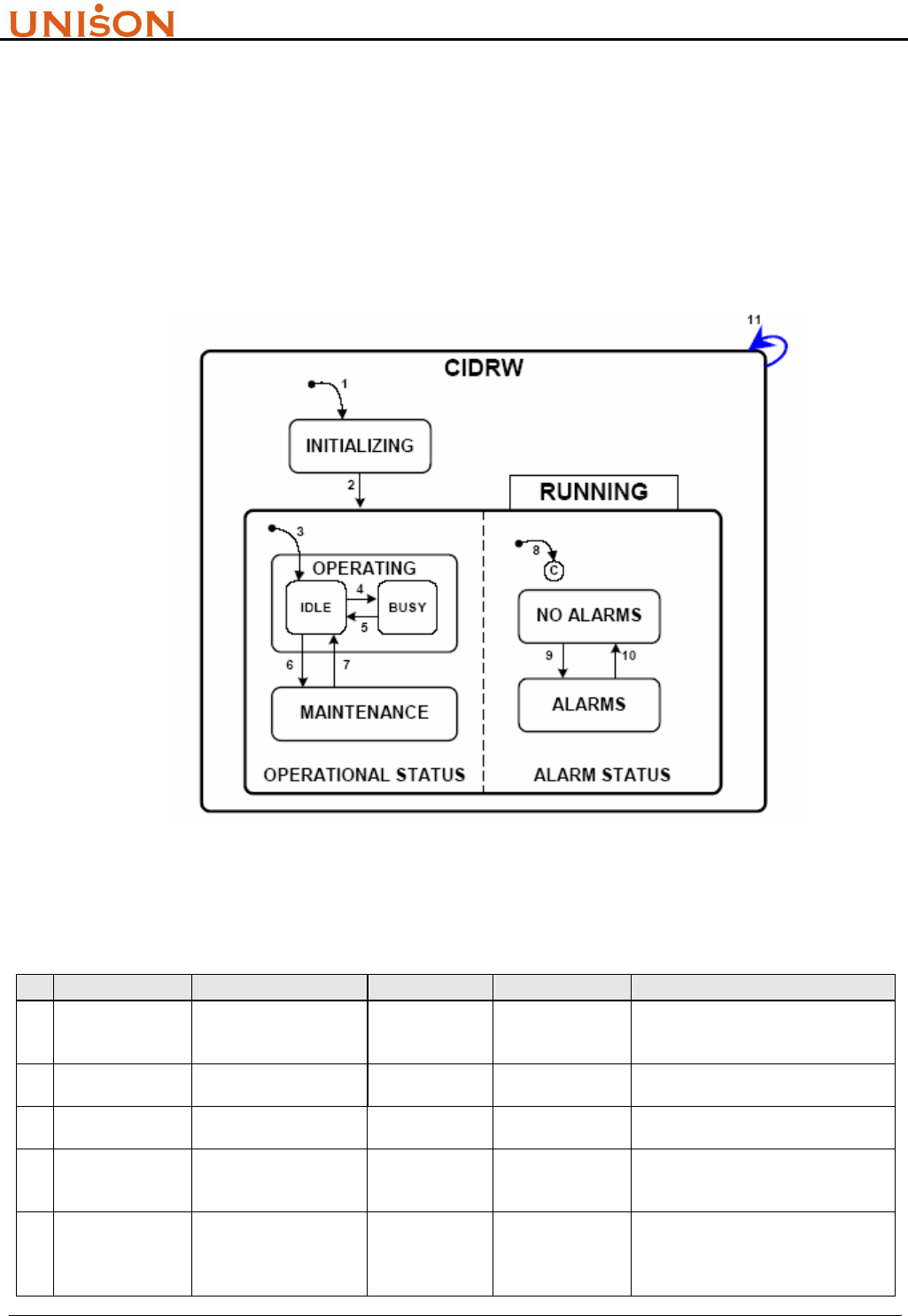
3.3.1. State Model and Transition
The state and state transition define the characteristics and behavior of RFID reader. Those
definitions can make upstream controller to understand how system is operating. Figure 3-1 and
Table 3-3 explain the meanings of state and transition.
Figure 3-1. CIDRW State Model Diagram
Table 3-3. CIDRW State Transitions
# Previous State Trigger New State Actions Comment
1 (Any) Power up or reset INITIALIZING
Initialize hardware
and software
components
Default entry on power up
2 INITIALIZING Initialization is
completed RUNNING None The CIDRW is now able to
communicate
3 INITIALIZING Default entry into
OPERATING IDLE None Internal
4 IDLE
A service request to
read or write or perform
diagnostics is received
BUSY None
5 BUSY
All services requests
that affect the state of
the hardware are
completed
IDLE None

RFID Transponder Reader User Manual Version:1.9
This document is prepared by UNISON Technology Inc. All rights reserved. Page 22 of 31
6 IDLE
A user selects the
MAINTENANCE state
and all heads are idle
MAINTENANC
E
None
The upstream controller may send a
request or the operator may set a
switch to select the OPERATING or
the MAINTENANCE state.
Maintenance and setup activities
may now be performed.
7 MAINTENANCE
A user selects the
OPERATING state and
all heads are idle.
IDLE None
The upstream controller may send a
request or the operator may set a
switch to select the OPERATING or
the MAINTENANCE state. Normal
operating activities may now be
performed.
8 INITIALIZING Default entry into
ALARM STATUS
ALARMS or
NO ALARMS None
9 NO ALARMS An alarm condition is
detected. ALARMS None
10 ALARMS All alarm conditions
have cleared NO ALARMS None
11 (Any) A reset service request
is received. CIDRW None
3.3.2. Services
“Services” mean the “function” which are supported by RFID reader. To be compliant with this
standard, the RFID reader shall support all services which are indicated as required in Table 3-4. In
practice, the corresponding SECS II stream functions are also given. The compliance can be
achieved by implementing the defined SECS protocol.
Table 3-4. Compliant Services List
Service Name Description Stream,Function
Fundamental Requirements
Get Attributes Get specified information about the CIDRW S18,F1/F2
Get Status Get the current status of the CIDRW S18,F13/F14
Read ID Read ID S18,F9/F10
Requirement for Reader/Writer
Read Data Read back data written previously (not applicable to
read-only devices) S18,F5/F6
Write Data Write data (not applicable to read-only devices) S18,F7/F8
Optional capabilities
Change State
Change to MAINTENANCE state or OPERATING state.
This is required if the device supports the optional WriteID
service.
S18,F13/F14
Perform
Diagnostics Perform diagnostic tests S18,F13/F14
Reset Reset CIDRW hardware and software S18,F13/F14
Set attributes Write specified information S18,F3/F4
Write ID Write ID field (device must also support Change State
service) S18,F11/F12
RFID Transponder Reader User Manual Version:1.9
This document is prepared by UNISON Technology Inc. All rights reserved. Page 23 of 31
3.3.3. Service Operability
SEMI E99 also defines the services operability under some CIDRW state. The valid services per
state are shown in Table 3-5.
Table 3-5. Valid Services per State
Service
Write ID
Write Data
Set
attributes
Reset
Read ID
Read Data
Perform
Diagnostics
Get Status
Get
attributes
Change
State
CIDRW State
INITIALIZING
OPERATING X X X X X X X X X
MAINTENANCE X X X X X X X X
4. ASCII OPERATION
Besides standard SEMI SECS I/II communication protocol, UNISON RFID Reader also support
ASCII command mode through RS232 port. It means host controller can communicate with
UNISON RFID Reader ether by SECS protocol or formatted ASCII string commands.
ASCII commands are categorized to host side and reader side. Section 4.1 and 4.2 will introduce the
commands usage.
4.1. HOST COMMAND FORMAT
Host command string format:
~xx cmd data1 data2 data3*
Fields description
Table 4-1. ASCII host command format
Item Code Description
1 ~ Start of command string
2 Xx The device ID, range from 00 ~07, two digits are required
3 Cmd Command name, which is listed in Table 4-2.
4 data1/data2/data3 Parameters for command
5 * End of command string

RFID Transponder Reader User Manual Version:1.9
This document is prepared by UNISON Technology Inc. All rights reserved. Page 24 of 31
Host commands list
Table 4-2. ASCII host command list
Item Command Format Parameter String
1 Are you there ~xx RU*
2 Read MID ~xx RMID*
3 Write MID ~xx WMID MIDstring* MIDstring: max16bytes
4 Read DATA ~xx RDAT startoffset datalength* Startoffset:000~119
Datalength: 001~120
5 Write DATA ~xx WDAT startoffset datalength datastring* Startoffset:000~119
Datalength:001~120
6 Write State ~xx WS yy* yy: 00 operation mode
yy: 01 maintenance mode
7 Read State ~xx RS*
4.2. READER COMMAND FORMAT
RFID reader reply command string format:
~xx cmdR rc data*
Fields description
Table 4-3. ASCII reader command format
Item Code Description
1 ~ Start of command string
2 xx The device ID, range from 00 ~07, two digits are required
3 cmdR The reply command name, which is listed in Table 4-4. “R” stands for “Reply”
4 rc Return code
5 data Parameters for the reply command
6 * End of command string
Reader commands list:
Table 4-4. ASCII reader command list
Item Command Format Parameter String
1 Are you there ~xx RUR softver*
2 Read MID ~xx RMIDR rc MIDstring*
3 Write MID ~xx WMIDR rc* MIDstring: max16bytes
4 Read DATA ~xx RDATR rc datastring* Startoffset:000~119
Datalength: 001~120
5 Write DATA ~xx WDATR rc* Startoffset:000~119
Datalength:001~120
6 Write State ~xx WSR rc*
7 Read State ~xx RSR rc*
8 Unknow command ~xx UNCMD*

RFID Transponder Reader User Manual Version:1.9
This document is prepared by UNISON Technology Inc. All rights reserved. Page 25 of 31
5. SETUP
5.1. INSTALLATION PROCEDURE
! Only install and operate this equipment if it is in perfect condition and with reference to this
manual. Do not use the equipment if it is damaged.
! This device is designed for use in an indoor industrial environment only. Installation is only
permitted in an environmental indoor.
! The device should not be used in the immediate vicinity of electrical units (such as medical units,
monitors, telephones, televisions and energy-saver lamps), magnetic data carriers, or metallic
objects. This could result in reduced reading/writing ranges.
! Do not install or use this device in or near water. Never spill liquids of any kind onto the device.
! Do not position the device in a location where it can suffer from vibration or shock.
! When installing the device, take extreme care not to encounter such circuits as they can cause
serious injury or death.
! Never expose the device to intense changes in temperature, otherwise condensation can develop
inside the device and cause damages.
! Ensure the installation location complies with FCC requirements for human exposure to radio
frequency.
! The installation shall be carried out by specially trained personnel only. If you are uncertain
about the qualification, contact the manufacturer.
)Operating the device without special skills can result in damage to the reader and/or connected devices!
! This product is designed to be mounted and operated in an industrial environment as a
built-in-device only. It is not designed to be used as a stand-alone or a portable device or in a
non-industrial environment, such as a household, vehicle or open-air environment.
A. Unpacking
Open the package, inspect the RFID reader controller and accessories including power
adaptor、RS232 Cable、Antenna and Cable.

RFID Transponder Reader User Manual Version:1.9
This document is prepared by UNISON Technology Inc. All rights reserved. Page 26 of 31
B. Mounting UNISON RFID Reader
Mount RFID reader controller to equipment or supporter by the hook which is beside the
controller. Please refer to section 2.2. (Mounting brackets are supplied by equipment dealer)
C. Mount Antenna
If stick type antenna is used, the antenna holder should be set up in somewhere first. Stick
antenna then is inserted to holder and fixed well. The distance between antenna holder and
RFID Reader controller can not exceed 1 meter of cable length.
D. Connect Antenna
Connect antenna cable BNC connector to RFID reader controller, and arrange the cable. Be
careful not to drag hard the antenna cable to avoid impacting signal transfer.
E. Connect RS232 connector
Connect RS232 cable RJ-45 connector to RFID reader controller, and arrange the cable.
F. Connect Power Adaptor
Finally connect the power adaptor to RFID reader controller.
5.2. INITIAL TEST PROCEDURE
A. Switch the DIPs on RFID reader controller to set Device ID.
B. Connect RS232 9 pins connector to equipment host or PC.
C. After connecting all cables then power on RFID reader controller.
D. Start up equipment host or PC’s application such as WinSECS.
E. Push “UP” and “DOWN” buttons simultaneously to do self test. RFID reader will read MID
data first and then write into ”0000000000000000” (only for multi page tag) data. During the
self test, the Read/Write indicator will light up once in order
F. From host side, check the MID data ”0000000000000000” are written to tag correctly.
G. Turn off RFID reader controller power, and then turn on again.
H. After RFID reader controller complete initialization, controller will send S18F71 message to
notify host the system is ready. If the working voltage exceeds the range of 5V+10%, the
controller will host and stop working.

RFID Transponder Reader User Manual Version:1.9
This document is prepared by UNISON Technology Inc. All rights reserved. Page 27 of 31
I. From host side, check if host receives S18F71 message or not.
J. From host side, test another SECS Stream Functions.
6. TROUBLE SHOOTING
6.1. ERROR INDICATOR
6.1.1. Watch Dog Timer
It is used to indicate the system is in normal operation or not. The red light will be flashing after
successfully initialization
6.1.2. Read/Write indicator
They are used to indicate the executing command is “read” or “write”. When command start to
execute, the light of indicator turn to green. Green color will be turned off if the command is
executed successfully. Otherwise, if the command execution is failed, the light of indicator will turn
to red, it will not turn off until next command is executed
6.2. ERROR RECOVERY
When abnormal condition occurs, first step is to check the Watch Dog Timer Indicator to justify the
abnormal condition is caused by RFID reader controller itself or communication problem.If the
Watch Dog Timer Indicator does not flash, it means RFID reader controller encounter some
troblem. To confirm this, power off controller and restart again (refer to section 5.2). If it still dose
not work, the best way is to change it and call support service. If the Watch Dog Timer Indicator is
still flashing, it means the abnormal condition may be caused by communication. Please check the
cable wire, and do communication test once again from host.
Please note, do not reset RFID reader controller CPU by yourself. The procedure should be done by
technical support.
RFID Transponder Reader User Manual Version:1.9
This document is prepared by UNISON Technology Inc. All rights reserved. Page 28 of 31
7. ACCESSORIES
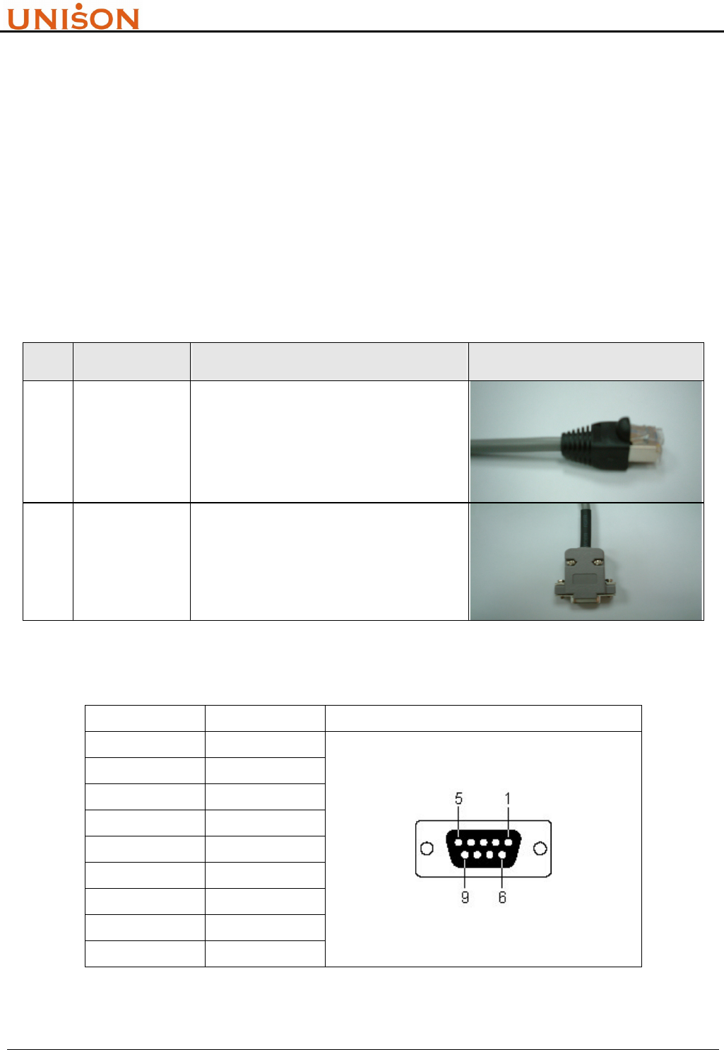
7.1. RS232
! When you disconnect a cable, pull on its conductor and not on the cable itself. Keep the
connector evenly aligned to avoid bending any connector pins. When you connect a cable,
ensure that the connector pins are positioned correctly.
! Before removing or inserting components, disconnect the power supply.
Table 7-1-1. RS232 Cable Spec (88-CBL-232-L5)
Item Component Spec Description Picture
1 RJ45 Plug RJ45 STP PLUG 50u", PC material
2 RS232 Cable STP Cat.5, 4P8C, PVC material
Table 7-1-2. RS232 pin definition
Pin No. Signal RS-232 9 Pin Female Connector
1 NC
2 TxD
3 RxD
4 NC
5 GND
6 NC
7 NC
8 NC
9 NC
RFID Transponder Reader User Manual Version:1.9
This document is prepared by UNISON Technology Inc. All rights reserved. Page 29 of 31
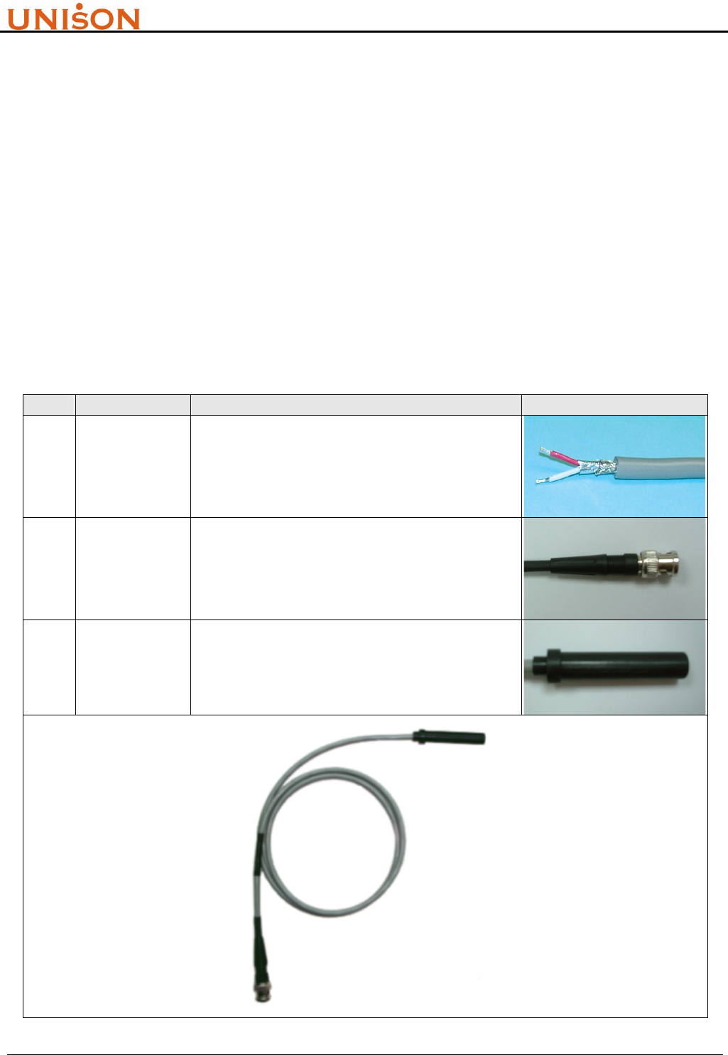
7.2. ANTENNA
! The device should not be used in the immediate vicinity of electrical units (such as medical units,
monitors, telephones, televisions and energy-saver lamps), magnetic data carriers, or metallic
objects. This could result in reduced reading/writing ranges.
! Never over bend the antenna cable or expose it to mechanical loads.
! Never locate the antenna so that it is very close to or touching parts of the body while
transmitting.
! Do NOT operate this device without a proper antenna attached. Proper antennas are antennas
supplied by the manufacturer and listed in section „Accessories“.
Table 7-2. Antenna Cable Spec (88-ANT-RD-L1)
Item Component Spec Description Picture
1 Cable
UL2464 two layer shield computer cable
(aluminum foil + copper mesh), 2C/1P, 1m in
length, PVC material
2 BNC
Connector
BNC Male 180degree 50Ω connector, 36mm in
length and 14.5mm in outer diameter
3 Housing Antenna Housing, POM material
RFID Transponder Reader User Manual Version:1.9
This document is prepared by UNISON Technology Inc. All rights reserved. Page 30 of 31
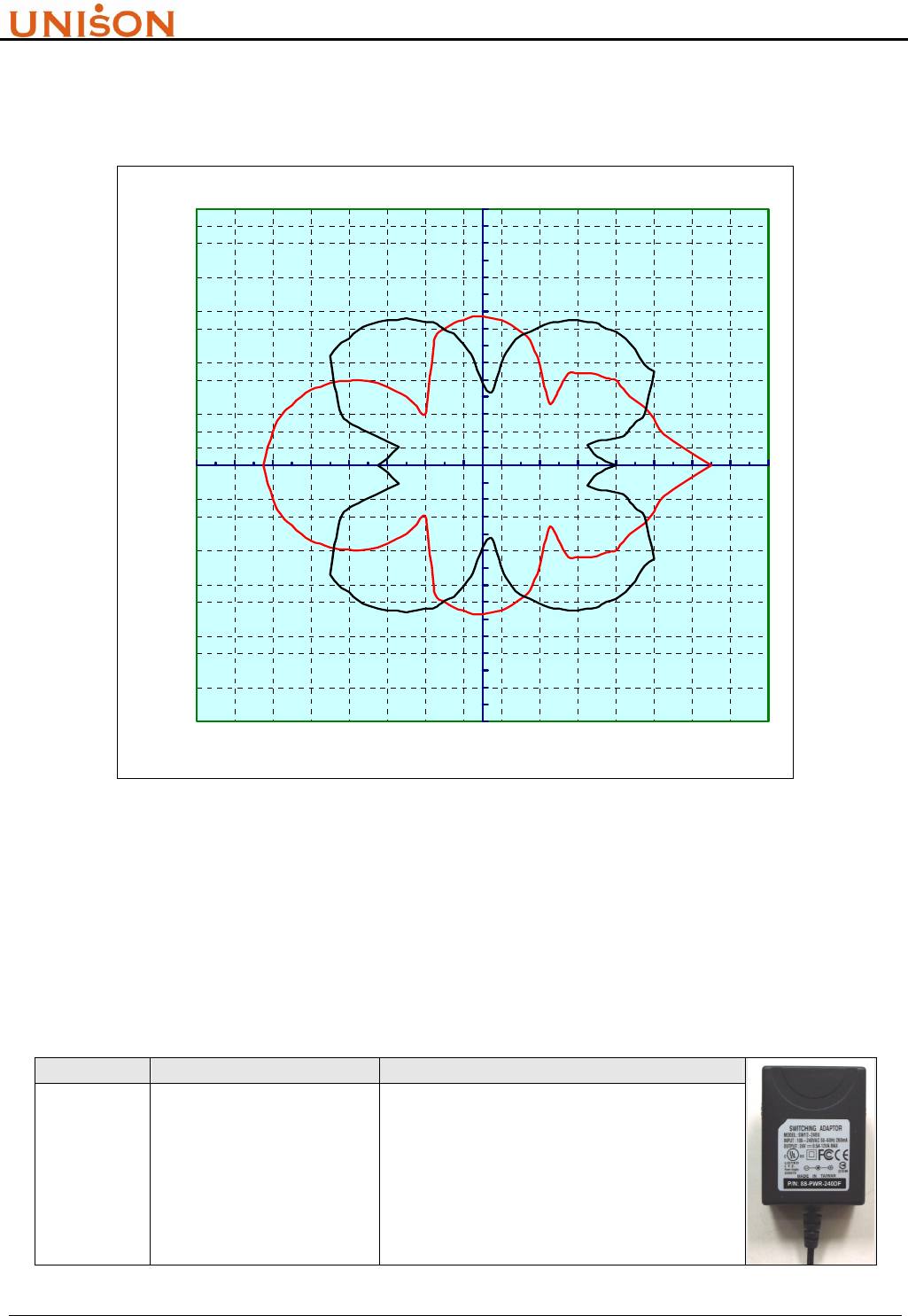
The readout diagram of antenna represents the detectable area for transponder (TI®, herein).
Figure 7-1 shows the typical readout diagram of stick type respectively.
Readout Diagram(red:parallel,black:vertical)
-15
-14
-13
-12
-11
-10
-9
-8
-7
-6
-5
-4
-3
-2
-1
0
1
2
3
4
5
6
7
8
9
10
11
12
13
14
15
-15-13-11-9-7-5-3-1 1 3 5 7 9111315
X (cm)
Y (cm)
Figure 7-1. Stick type antenna readout diagram
7.3. POWER ADAPTER
! Do not connect the device to any kind of power supply such as a standard household power
supply. The device should be connected to a power supply of the type described in these
instructions only.
Table 7-3. Switching Power Adaptor (88-PWR-240DF)
Item Component Spec Description
1 AC to DC Converter
Input 100-240VAC 50-60Hz
Output 24V 0.8A
Safety Approval:
FCC / CE / CUL / PSE / BSMI

RFID Transponder Reader User Manual Version:1.9
This document is prepared by UNISON Technology Inc. All rights reserved. Page 31 of 31
8. ERVICE INFORMATION
This product is developed and manufactured by UNISON Technology, Inc. ABON-TECH
INTERNATIONAL CORP is the product agent for Sales and Service
ABON-TECH International Corp. (Headquarter)
13F-2, No. 289, Sec. 2, Kuang-Fu Rd.,
Hsinchu, Taiwan R.O.C.
Tel.: +886-3-572-1959 Ext. 301
Fax.: +886-3-572-1990
ABON-TECH International Corp. (Tainan Branch)
2F, No. 140, Cheng-Kou Rd.,
Shanhua, Tainan R.O.C.
Tel.: +886-6-583-3458
Fax.: +886-6-583-0740, 583-4250
ABON-TECH International Corp. (Shanghai Branch)
Room G, 10F, No. 432, Huai-Hai Xi Rd.,
Xu Hui District, Shanghai 200052, China
Tel.: +86-21-6282-0387, 6282-0385
Fax.: +86-21-6283-6567