Access BGR135 Boarding Gate Reader User Manual BGR135 manual
Access Ltd Boarding Gate Reader BGR135 manual
Access >
Contents
- 1. BGR135_manual
- 2. BGR135C_Boarding_Gate_Reader_with_NFC_Datasheet
BGR135_manual

Page 1 of 12 Revision 1 Access Limited 2011 - All Rights Reserved
BGR135
1D and 2D BCBP Boarding
Gate Reader
Product Specification
Revision 1

Page 2 of 12 Revision 1 Access Limited 2011 - All Rights Reserved
About this manual
BGR135 - Installation and Use
First Edition (Jan 2011) (c) 2011 Access Ltd.
Part No. BGR135 www.access-is.com
All rights reserved. Whilst every precaution has been taken in the preparation of this manual,
Access Ltd assumes no responsibility for errors or omissions. Neither is any liability assumed for
damages resulting from the use of the information contained herein. We reserve the right to change
the specifications, functions and circuitry of the product without notice. All trademarks
acknowledged.
Warnings
This manual contains important information regarding the installation and operation of the BGR135
Boarding Gate Reader. For safe and reliable operation of the product, all users must ensure that
they are familiar with and fully understand all instructions contained herein.
Warranty
Access Ltd warrants that this product shall be free from defects in workmanship and materials for a
period of one year from the date of original purchase. If the product should fail to operate correctly
in normal use during the warranty period, Access will replace or repair it free of charge. No liability
can be accepted for damage due to misuse or circumstances outside Access control. Also Access
will not be responsible for any loss, damage or injury arising directly or indirectly from the use of this
product. Access total liability under the terms of this warranty shall in all circumstances be limited to
the replacement value of this product.
If any difficulty is experienced in the installation or use of this product that you are unable to
resolve, please contact Access.
Trademarks
All trademarks mentioned in this manual are acknowledged to be the property of the respective
trademark owners.Access Keyboards is a registered trademark of Access Keyboards Limited.
IBM, PC/AT, PS/2 are registered trademarks of International Business Machines Corporation.
Microsoft and Windows are registered trademarks of Microsoft Corporation.

Page 3 of 12 Revision 1 Access Limited 2011 - All Rights Reserved
Radio Frequency Energy
European EMC directive 89/336/EEC
This equipment has been tested and found to
comply with the limits for a class A computing
device in accordance with the specifications in the
European standard EN55022. These limits are
designed to provide reasonable protection against
harmful interference. This equipment generates,
uses and can radiate radio frequency energy and
if not installed and used in accordance with the
instructions may cause harmful interference to
radio or television reception. However, there is no
guarantee that harmful interference will not occur
in a particular installation. If this equipment does
cause interference to radio or television reception,
which can be determined by turning the equipment
on and off, the user is encouraged to correct the
interference with one or more of the following
measures (a) Reorient or relocate the receiving
antenna. (b) Increase the separation between the
equipment and the receiver. (c) Connect the
equipment to an outlet on a circuit different from
that to which the receiver is connected. (d) Consult
the supplier or an experienced radio / TV
technician for help.
FCC Compliance Statement (United States)
This equipment generates, uses and can radiate
radio frequency energy and if not installed and
used properly, that is, in strict accordance with the
manufacturer’s instructions, may cause
interference to radio communication. It has been
tested and found to comply with the limits for a
class A computing device in accordance with the
specifications in Subpart J of part 15 of FCC rules,
which are designed to provide reasonable
protection against such interference when the
equipment is operated in a commercial
environment. Operation of this equipment in a
residential area may cause interference, in which
case the user at his own expense will be required
to take whatever measures may be necessary to
correct the interference. Changes or modifications
not expressly approved by the manufacturer could
void the user’s authority to operate the equipment.
Canadian Department of Communications RFI
statement
This equipment does not exceed the class A
limits for radio noise emissions from digital
apparatus set out in the radio interference
regulations of the Canadian Department of
Communications.
Le présent appareil numérique n’émet pas de
bruits radioélectriques dépassant les limites
applicables aux appareils numériques de la classe
A prescrites dans le règlement sur le brouillage
radioélectriques publié par le ministère des
Communications du Canada.
Revision History
Rev 1 Jan 2011 Original

Page 4 of 12 Revision 1 Access Limited 2011 - All Rights Reserved
Contents
Contents
1. Overview .............................................................................................................................. 5
2. Specifications ....................................................................................................................... 6
2.1 BGR ................................................................................................................................................ 6
2.2 Bi-colour LEDs ............................................................................................................................... 6
2.3 Internal Sounder ............................................................................................................................. 6
3. Data Format Protocol ........................................................................................................... 8
4. Installation ............................................................................................................................ 9
4.1 BGR Connection ............................................................................................................................ 9
4.2 BGR Configuration ....................................................................................................................... 10
5. Operation ........................................................................................................................... 11
5.1 Barcode Reading .......................................................................................................................... 11
6. Maintenance…………………………………………………………………………………………………..12

Page 5 of 12 Revision 1 Access Limited 2011 - All Rights Reserved
1. Overview
The Access BGR135 is a compact Boarding Gate Reader for 2D Bar Coded Boarding Passes and NFC
device. The BGR135 features
Fixed focal length, regardless of bar code size. The operator does not have to find the optimum
reading position.
Omni-directional reading. The bar code may be inserted at any angle.
Wide document throat. The imager can read a bar code printed at any position on an A4 (European)
or Letter (American) document.
Programmable visible and audible indication give an easy “go / no-go” indication to the operator.
Robust unit with a small footprint, which may be easily secured to the check-in desk using the
optional quick-release bracket (see section 4.2)
Compatible with dedicated airline and common-user departure control systems.
Highly visible red/green LEDs
and audible alarm provide positive
read confirmation to the agent.
VFD display can be easily read
over a wide range of angles, and
in bright ambient lighting conditions.
Wide document throat facilitates
reading of barcode at any position
on an A4 document.
Omni-directional and fixed-focus
design allows easy and instant
reading of linear and 2D bar codes
regardless of size and orientation.
Wide reception area reads NFC cards
and phones quickly and easily.
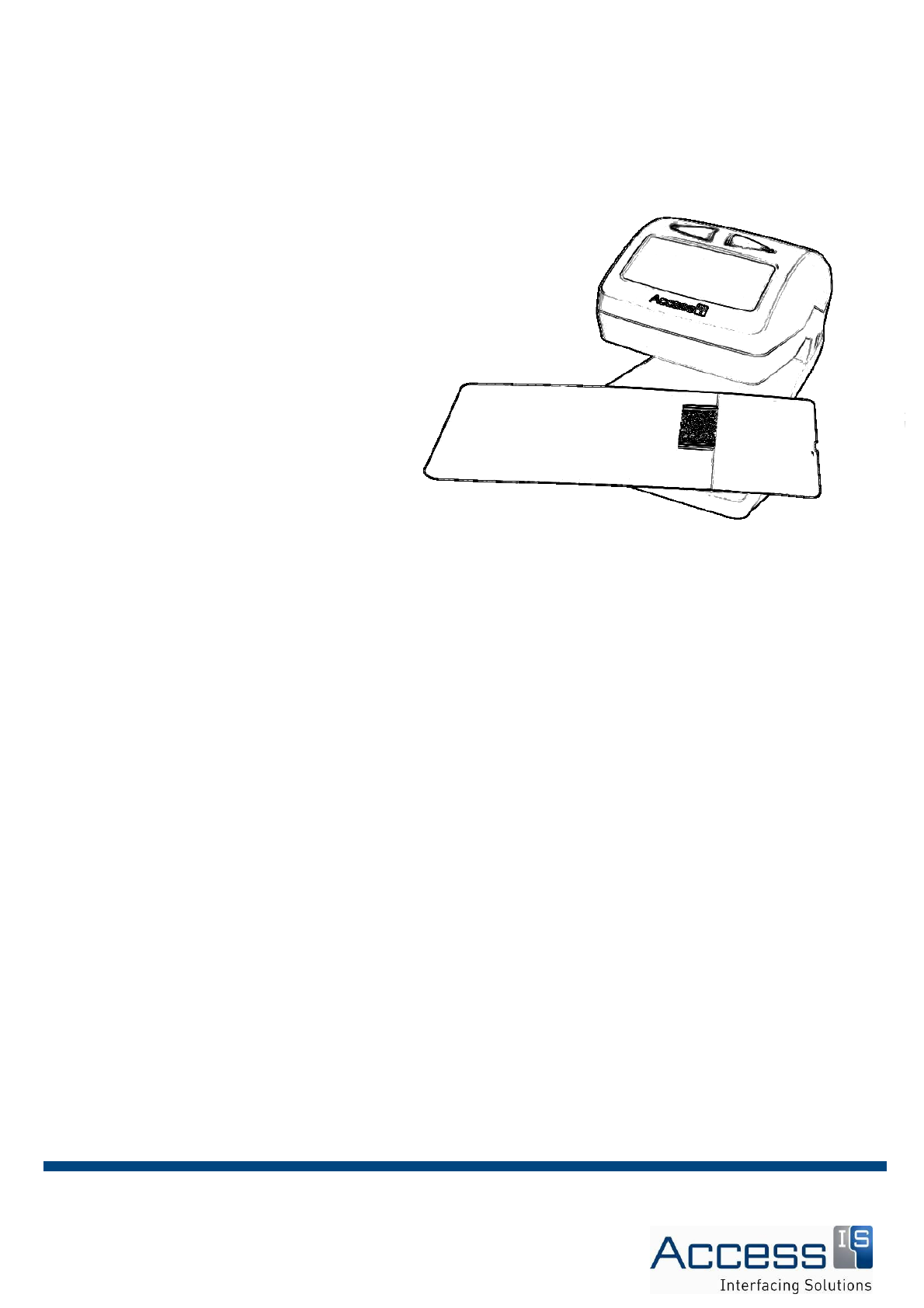
Can read barcodes from most mobile phones or PDAs.
Can read linear barcodes of up to 80mm presented
At any angle. It may be possible to read longer
linear barcodes up to a maximum of approximately
90mm by presenting them at an angle as shown.

Page 6 of 12 Revision 1 Access Limited 2011 - All Rights Reserved
2. Specifications
2.1 BGR
Dimensions Length 185mm
Height 142mm
Width 130mm
Weight 750g (excluding cable)
Colour Dark Grey
Environmental Operating temperature 0º to 50ºC
Storage temperature 0º to 60ºC
Humidity 0 to 95%, non-condensing
Power Requirements 9V to 15V DC.
BGR135 is supplied with a “universal” AC power supply, 100-240V
50/60Hz
Electrical Interface Serial (RS-232)
Bar Codes Linear Code 2 of 5, Interleaved 2 of 5, IATA 2 of 5, Code 3 of 9, Code
128
2D PDF417, QR, Aztec, DataMatrix
Performance Will read in full sunlight.
Can read bar codes from most mobile phone and PDA displays.
MTBF 85 000 hours
Approvals FCC Class B
CE EMC Class B
CE Low Voltage Directive
IEC60825-1 LED Safety Class 1
2.2 Bi-colour LEDs
A green LED of programmable duration is illuminated in response to a message from the host
computer indicating that a valid boarding pass has been accepted.
A red LED of programmable duration is illuminated in response to a host message indicating that
the boarding pass was invalid.
2.3 Internal Sounder
The BGR135 contains a sounder whose pitch and duration can be programmed for “accept” and
“reject”, and which may be addressed by the host computer.

Page 7 of 12 Revision 1 Access Limited 2011 - All Rights Reserved
2.4 Display
The BGR135 contains a 2 line x 16 character VFD display, which may be addressed by the host
computer.

Page 8 of 12 Revision 1 Access Limited 2011 - All Rights Reserved
3. Data Format Protocol
The BGR135 will normally be delivered factory-configured to work within the common use or shared
environment specified by the customer. It has been certified by SITA, ARINC, Ultra and RESA, and
complies with AEA2009 specifications, including 2D symbologies and headers.
For non-common use or shared applications, or for assistance with changing the host protocol,
please contact Access sales department on +44 118 966 3333 or email sales@access-is.com.
Page 9 of 12 Revision 1 Access Limited 2011 - All Rights Reserved
4. Installation
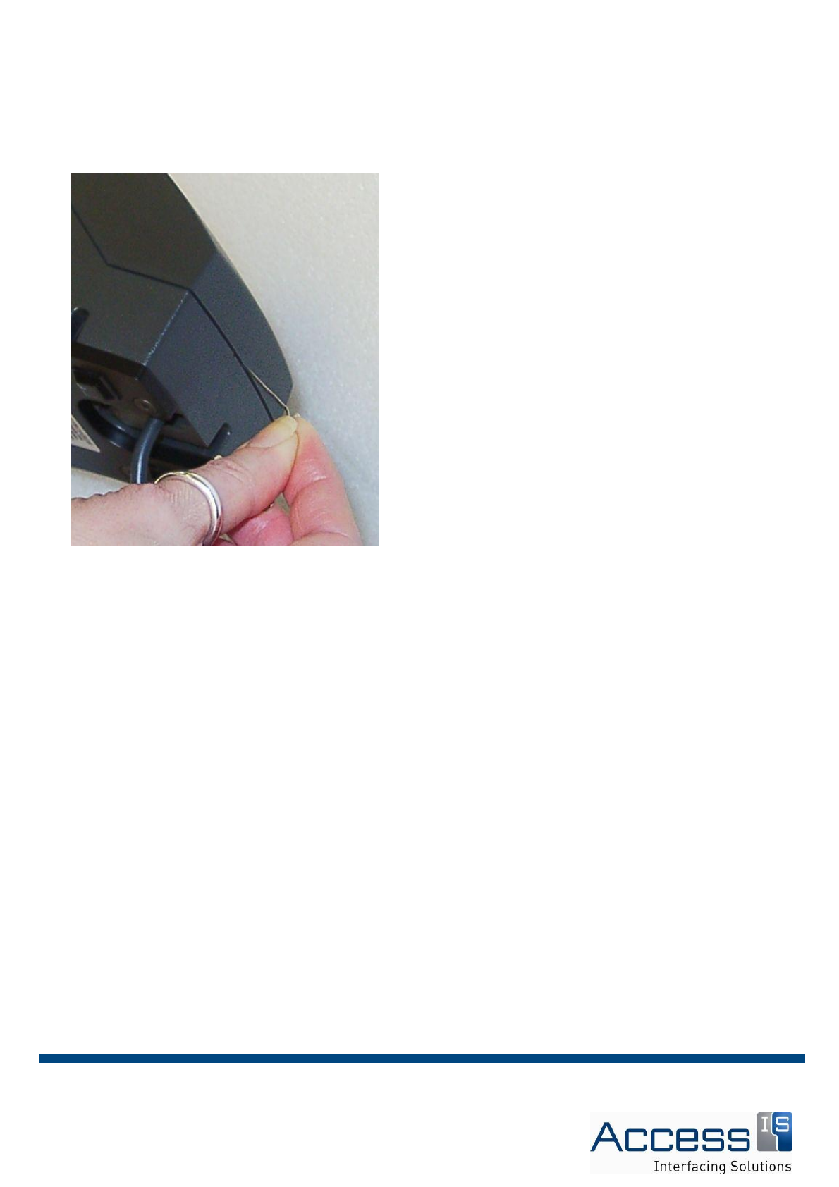
4.1 BGR Connection
The BGR135 connects by means of an RJ-50 10-pin
modular socket on the back of the unit.
To connect the BGR135 cable, push the connector
into the host socket until you hear a click. The host
socket is clearly marked as can be located closest to
the power switch.
To remove the cable the connecting lug must be
depressed while the cable is gently pulled to
disconnect it.
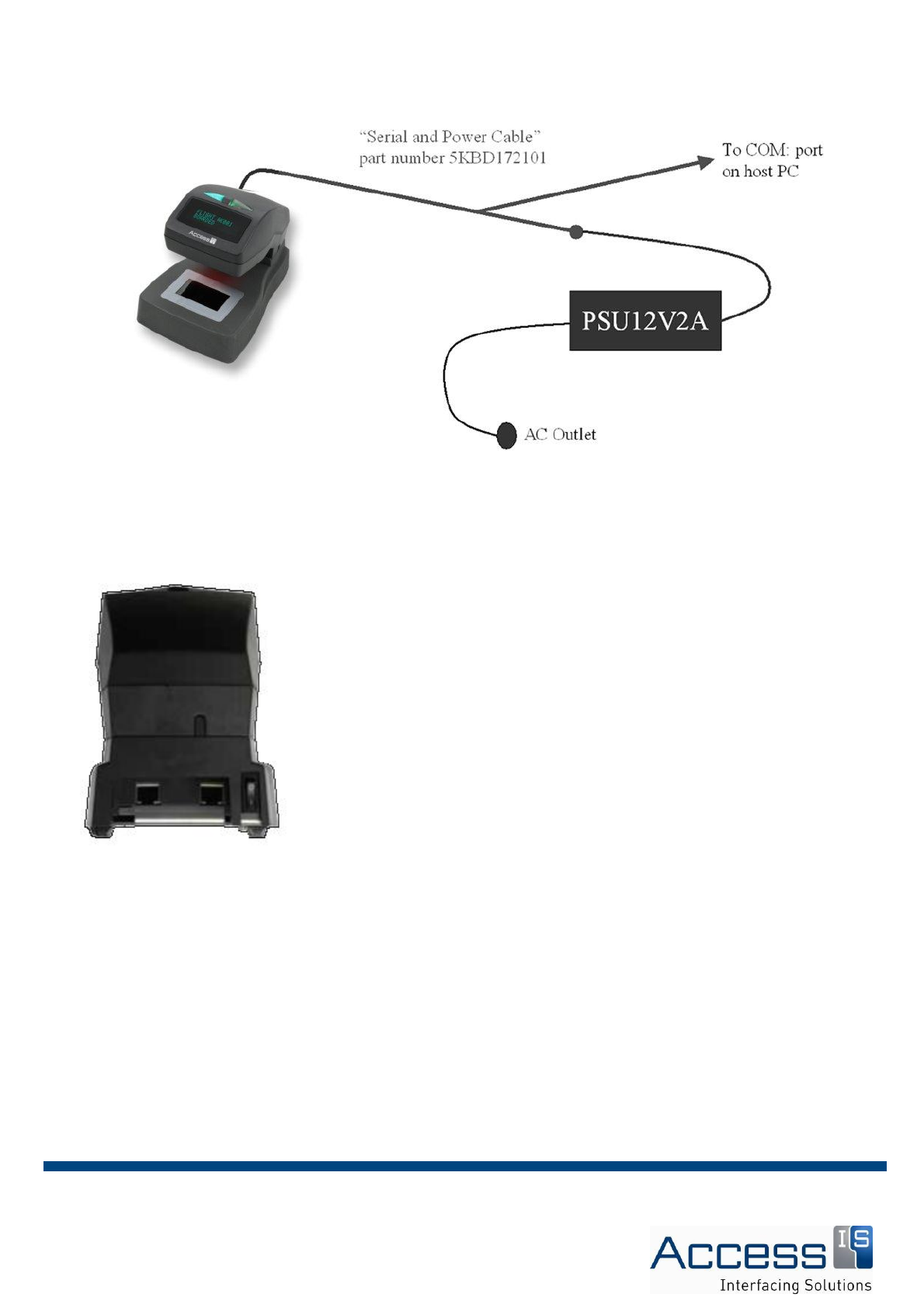
The BGR135 is supplied with the following accessories
5KBD172102 Serial and Power Cable
PSU12V2A Universal AC Power Supply
Page 10 of 12 Revision 1 Access Limited 2011 - All Rights Reserved
These are connected as depicted below
The BGR135 features a RJ45 port for receipt printing functionality as well as an on/off switch. Both
are located to the rear base of the unit – see attached illustration.
4.2 BGR Configuration
The BGR135 serial port configuration, including the host protocol, may be achieved in either of the
following ways
1/ Using the Access “ZippyTools” utility.
2/ Using a configuration barcode provided by Access.
Page 11 of 12 Revision 1 Access Limited 2011 - All Rights Reserved
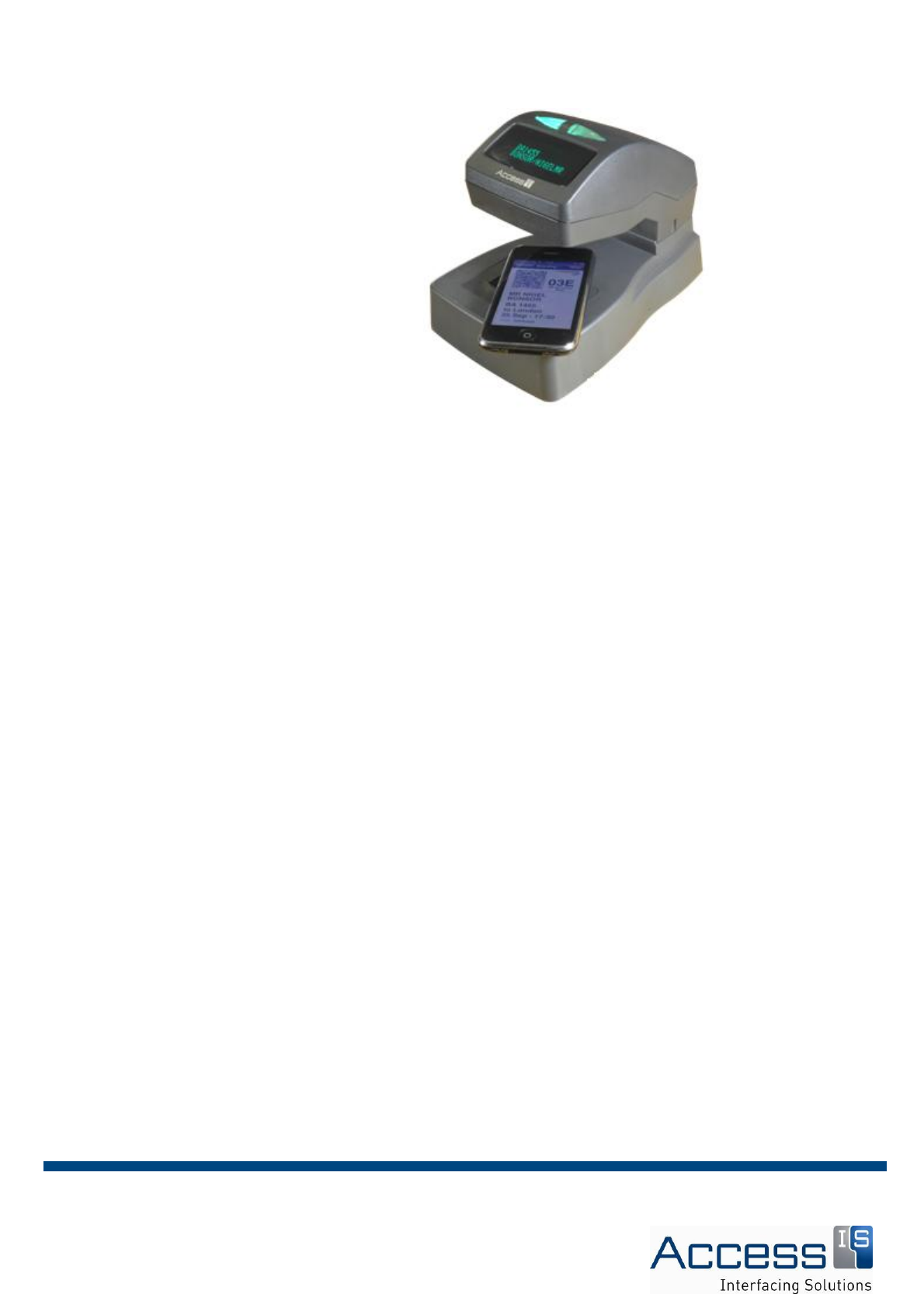
To read a bar coded boarding pass,
place the document face-up into the bar
code reader zone. As soon as a
document is detected, the bar code
reader’s LEDs will illuminate the
document (a bar code on a mobile
phone or PDA will be automatically
illuminated at a lower level than a bar
code on a paper document).
The bar code imager is omni-
directional, and a well-printed document
should be read almost immediately.
Better read performance will be
achieved if the document is held flat on
the surface under the bar code reader.
The boarding application will determine
if the document is valid, and a message
will be sent to the operator message
display. Either the green LED (OK to
Board) or the red LED (Do Not Board)
will be illuminated.
5. Operation
5.1 Barcode Reading
Page 12 of 12 Revision 1 Access Limited 2011 - All Rights Reserved
Limited maintenance of the BGR135 is
required as essentially the unit is free
from moving parts and the glass
window is protected.
General, monthly cleaning of the sensor
window and imager window (underside
of unit) is recommended to remove any
dust and build up of debris.
6.0 Maintenance