Access CPM01 Contactless Payment Module (CPM01) User Manual Users manual
Access Ltd Contactless Payment Module (CPM01) Users manual
Access >
Users manual

Contactless Payment Module (CPM)
Installation Manual
1
Installation manual - v0.1
Contactless Payment Module
Installation Manual

Contactless Payment Module (CPM)
Installation Manual
2
Installation manual - v0.1
1. Introduction
This document describes the hardware of the Contactless Payment Module (CPM). The readers of this document
would benefit if they have prior knowledge of the specifications mentioned in References section.
2. References
The readers of this document shall have knowledge on the following specifications
USB CCID rev1.1 : Specification for Integrated Circuit Cards Interface Devices
ISO/IEC 14443-2 : Radio frequency power and signal interface
ISO/IEC 14443-3 : Initialisation and anti-collision
ISO/IEC 14443-4 : Transmission protocol
Mifare contactless card (Classic 1K, Classic 4K and Ultralight) datasheets
ISO/IEC 7816-3 : Electronic signals and transmission protocols
ISO/IEC 7816-4 : Inter-Industry commands for interchange
CPM USB/Serial software reference manual
3. FCC Statement
This device complies with Part 15 of the FCC Rules. Operation is subject to the following two conditions:
(1) this device may not cause harmful interference, and
(2) this device must accept any interference received, including interference that may cause undesired
operation.
No changes shall be made to the equipment without the manufacturer’s permission as this may void the user’s
authority to operate the equipment
It is the responsibility of the product manufacturer to ensure compliance with FCC Part 15B with the Contactless
Smartcard Module integrated into their product.
The host product using CPM module shall have the following text on a permanent label.
Contains FCC ID : ZERCPM01
The label should be on a visible location outside the enclosure of the product.
Contactless Payment Module (CPM)
Installation Manual
3
Installation manual - v0.1
4. Industry Canada Statement
This device complies with Industry Canada licence‐exempt RSS standards. Operation is subject to the following
two conditions:
1. This device may not cause interference.
2. This device must accept any interference, including interference that may cause undesired
operation of the device.
Under Industry Canada regulations, this radio transmitter may only operate using an antenna of a type and
maximum (or lesser) gain approved for the transmitter by Industry Canada. To reduce potential radio
interference to other users, the antenna type and its gain should be so chosen that the equivalent isotropically
radiated power (e.i.r.p.) is not more than that necessary for successful communication.
This device complies with the safety requirements for RF exposure in accordance with RSS-102 Issue 5 for
portable use conditions.
This radio transmitter (IC : 9653A‐CPM01) has been approved by Industry Canada to operate with the antenna
types listed below with the maximum permissible gain indicated *. Antenna types not included in this list,
having a gain greater than the maximum gain indicated for that type, are strictly prohibited for use with this
device.
* (and required antenna impedance for each antenna type indicated)
Parameter
Minimum
Typical
Maximum
Impedance @13.56MHz
800 Ohms
1500 Ohms
-
Phase @ 13.56MHz
-10 Degrees
0 Degrees
+10 Degrees
Antenna Coil inductance
700nH
1200nH
2000nH
Antenna Coil Q
30
25
100
Antenna Gain
0.6 (-2.21 dB)
0.7 (-1.54 dB)
0.8 (-0.96 dB)
Antenna maximum size
-
-
11cm x 15cm
The host product using CPM module shall have the following text on a permanent label.
Contains IC : 9653A-CPM01
The label should be on a visible location outside the enclosure of the product.
Contactless Payment Module (CPM)
Installation Manual
4
Installation manual - v0.1
5. Conformité IC
Le présent appareil est conforme aux CNR dʹIndustrie Canada applicables aux appareils radio exempts de
licence. Lʹexploitation est autorisée aux deux conditions suivantes :
1. Lʹappareil ne doit pas produire de brouillage.
2. Lʹutilisateur de lʹappareil doit accepter tout brouillage radioélectrique subi, même si le brouillage est
susceptible dʹen compromettre le fonctionnement.
Conformément à la réglementation dʹIndustrie Canada, le présent émetteur radio peut fonctionner avec une
antenne dʹun type et dʹun gain maximal (ou inférieur) approuvé pour lʹémetteur par Industrie Canada. Dans le
but de réduire les risques de brouillage radioélectrique à lʹintention des autres utilisateurs, il faut choisir le type
dʹantenne et son gain de sorte que la puissance isotrope rayonnée équivalente (p.i.r.e.) ne dépasse pas
lʹintensité nécessaire à lʹétablissement dʹune communication satisfaisante.
Cet appareil est conforme avec les exigences de sécurité pour l’exposition aux radiofréquences conformément
au CNR-102, 5e édition, pour les conditions d’utilisation portables.
Le présent émetteur radio (IC : 9653A‐CPM01) a été approuvé par Industrie Canada pour fonctionner avec les
types dʹantenne énumérés ci‐dessous et ayant un gain admissible maximal indiqué *. Les types dʹantenne non
inclus dans cette liste, ou dont le gain est supérieur au gain maximal indiqué, sont strictement interdits pour
lʹexploitation de lʹémetteur.
* (et l'impédance d'antenne requise pour chaque type indiqué d'antenne)
Parameter
Minimum
Typical
Maximum
Impedance @13.56MHz
800 Ohms
1500 Ohms
-
Phase @ 13.56MHz
-10 Degrees
0 Degrees
+10 Degrees
Antenna Coil inductance
700nH
1200nH
2000nH
Antenna Coil Q
30
25
100
Antenna Gain
0.6 (-2.21 dB)
0.7 (-1.54 dB)
0.8 (-0.96 dB)
Antenna maximum size
-
-
11cm x 15cm
Le produit de l'hôte en utilisant le module CPM a le texte suivant sur une étiquette permanente.
Contient IC : 9653A-CPM01
L'étiquette doit être sur un emplacement visible à l'extérieur de l'enceinte du produit.
Contactless Payment Module (CPM)
Installation Manual
5
Installation manual - v0.1
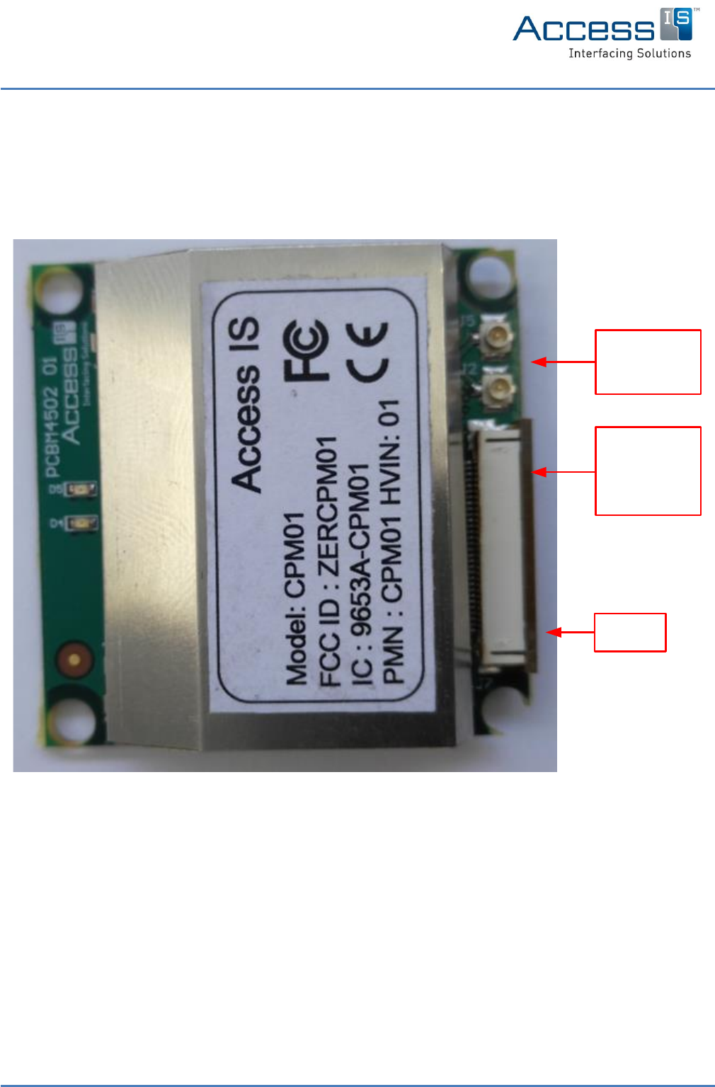
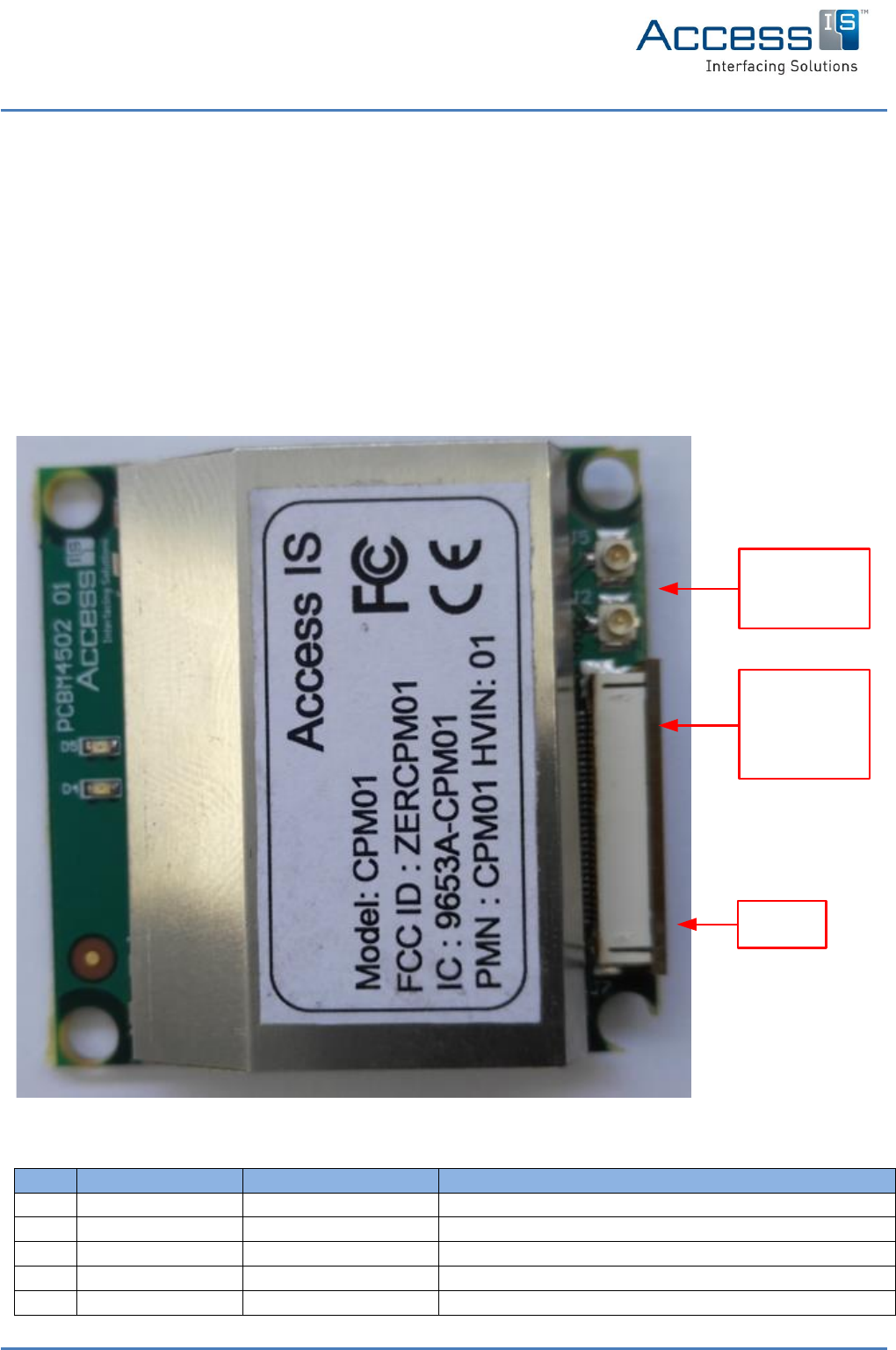
6. Product pictures
6.1. CPM – Top view with Shield
Antenna
connector
30 Way
Host
connector
PIN 1
Contactless Payment Module (CPM)
Installation Manual
6
Installation manual - v0.1
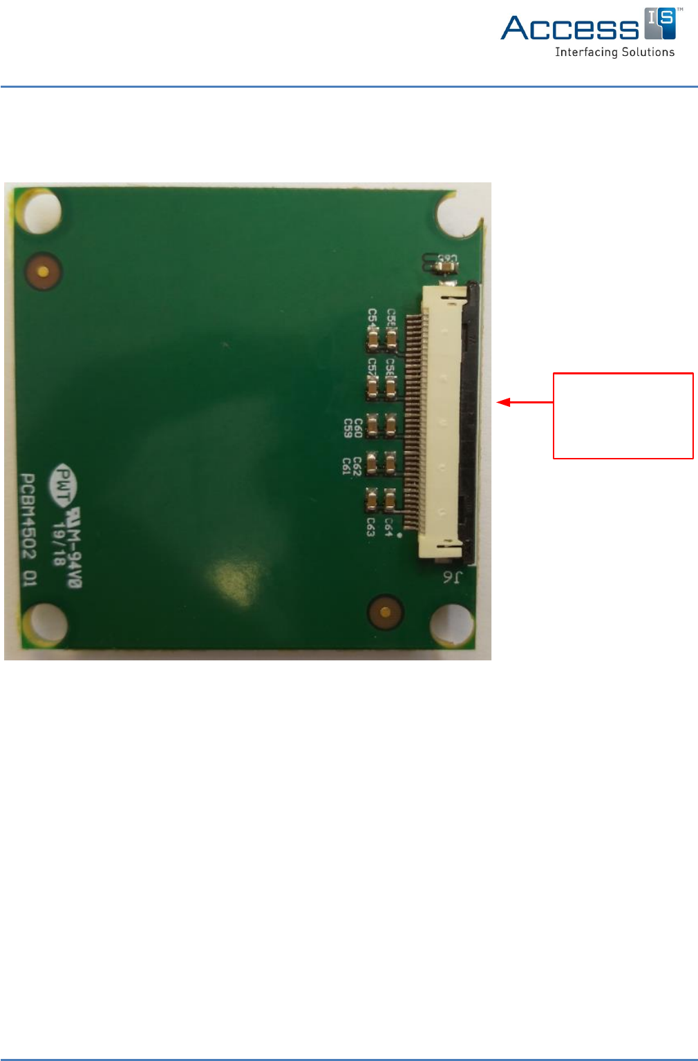
6.2. CPM – Bottom view
40 Way
4x Smartcard/
PSAM connector
Contactless Payment Module (CPM)
Installation Manual
7
Installation manual - v0.1
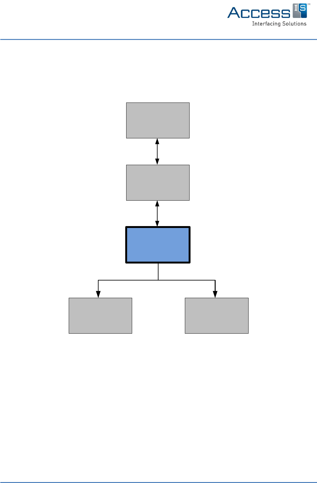
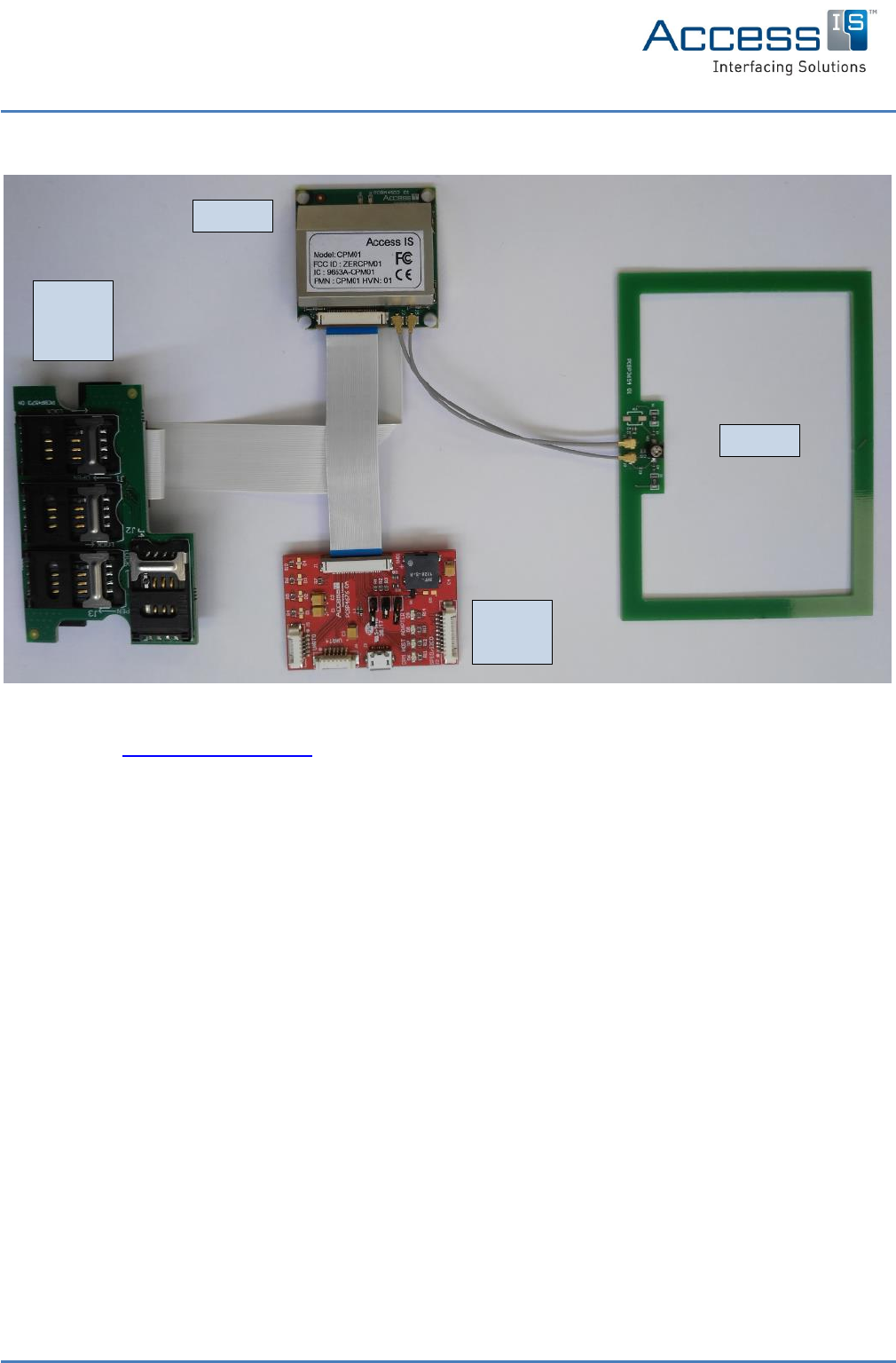
6.3. Typical Hardware Setup
The following diagram and pictures shows a typical setup for CPM module.
Host Adapter
CPM module
1x NFC Antenna 4x External
1x Internal
SIM carrier
USB or Serial
Host
Contactless Payment Module (CPM)
Installation Manual
8
Installation manual - v0.1
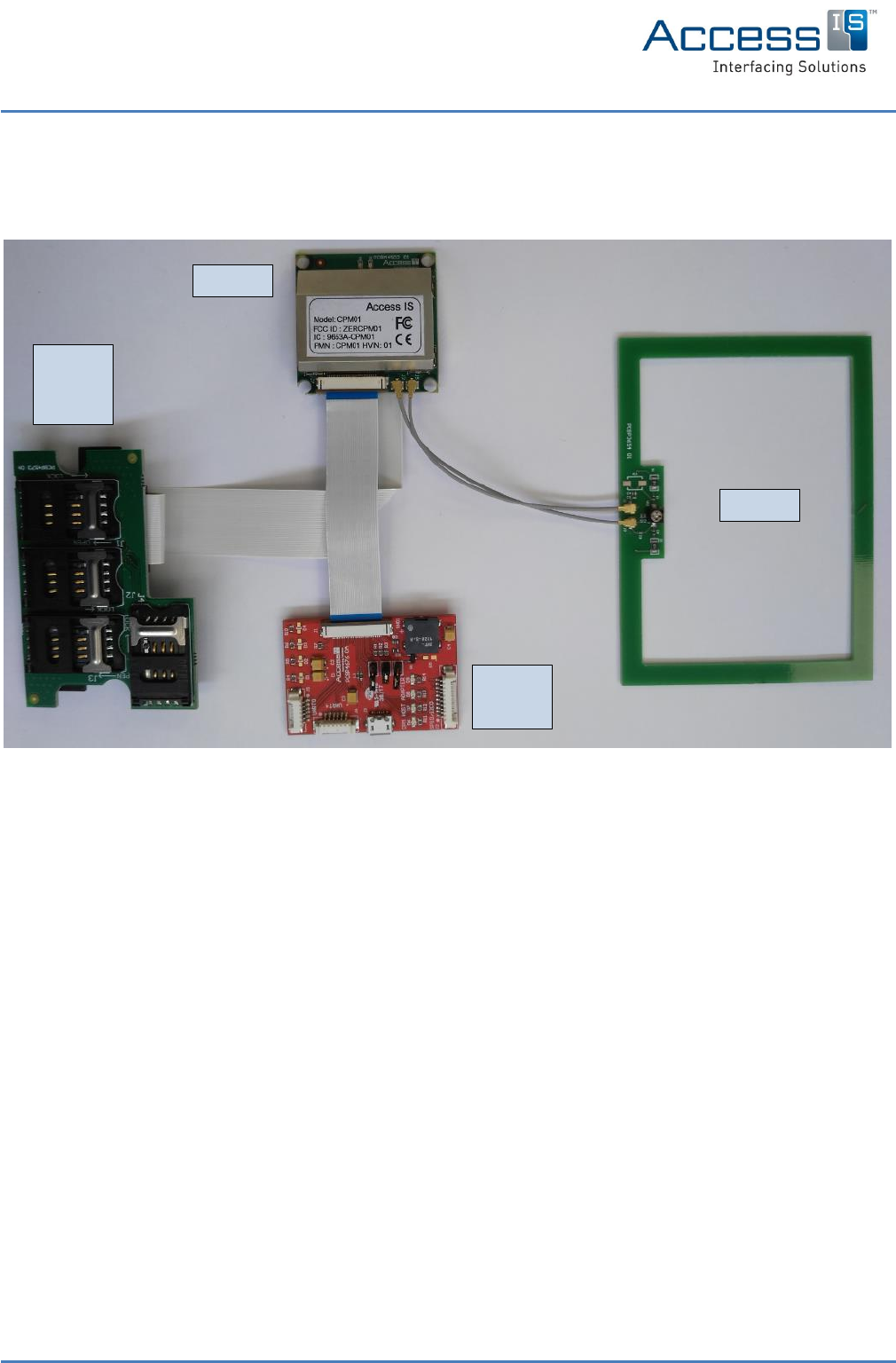
The following picture shows a typical setup. Note that the antenna and the Serial/USB host shown in the
pictures are for illustration only. The actual size and shape of the user’s antenna and host system may vary. If
the SIM functionality is not required, then the SIM carrier board need not be connected.
CPM
USB or
Serial Host
System
Antenna
5x SIM
Carrier
board
Contactless Payment Module (CPM)
Installation Manual
9
Installation manual - v0.1
6. Installation
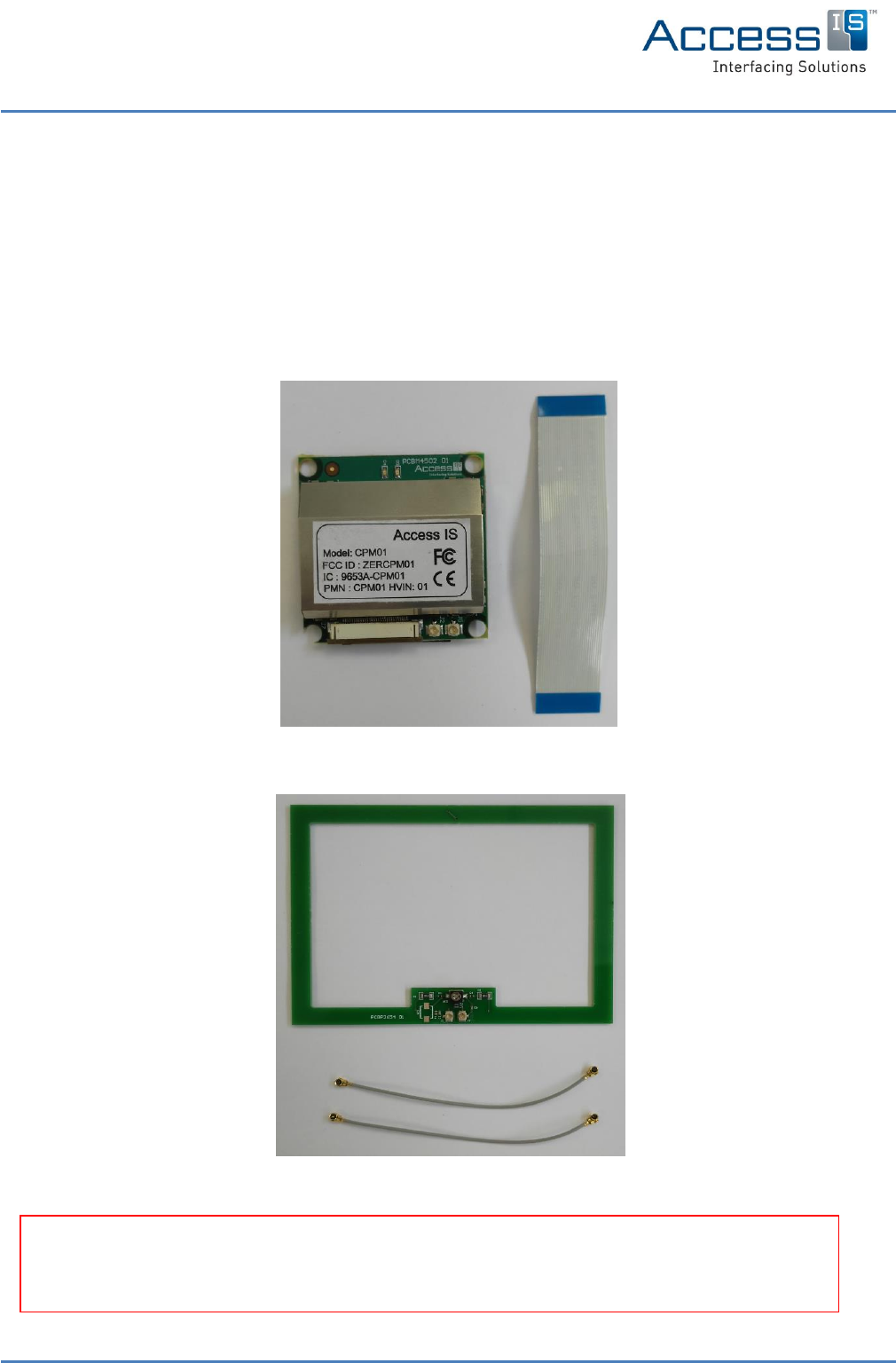
a. Hardware Prerequisites
The following section shows the hardware required for the installation.
Serial or USB host system where the CPM module will connect to.
CPM module and 30 way host FFC cable
Antenna and two U.FL coax cables
NOTE: The Antenna and the U.FL coax cables can be supplied by Access IS or the user can design
the antenna using the support provided by Access IS. U.FL cables are widely available from
electronics stores like RS/Farnell.
Contactless Payment Module (CPM)
Installation Manual
10
Installation manual - v0.1
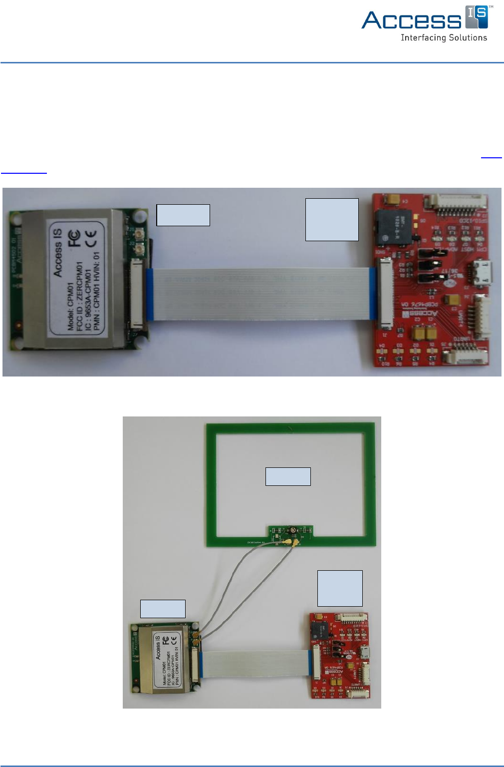
b. Hardware Installation Steps
The following details the installation steps with diagrams.
1, Turn OFF power for the host system before starting the installation
2, Connect the host system to the CPM module using the 30 way FCC cable as shown below. Please refer to Host
connector section for the connector location and its pinouts.
CPM USB or
Serial Host
System
3, Connect the antenna to the NFC module using the coax cables.
CPM
USB or
Serial Host
System
Antenna
Contactless Payment Module (CPM)
Installation Manual
11
Installation manual - v0.1
4, If SIM function is required, then connect the 5x SIM carrier board as shown below.
CPM
USB or
Serial Host
System
Antenna
5x SIM
Carrier
board
5, After the connections are done, select/verify the correct host interface selection on HOST_IFSEL_IO pins.
Please refer to Host Interface Selection for HOST_IFSEL_IO pin settings.
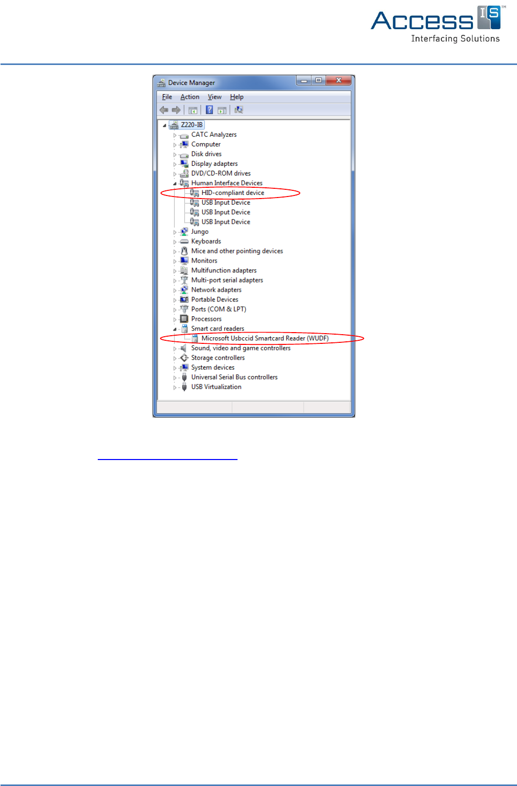
6, Power up the host system. Now, the CPM module should start working. If the host interface is USB, then NSM
module shall start enumerating as a HID device and a smartcard reader as shown in the next page.
Contactless Payment Module (CPM)
Installation Manual
12
Installation manual - v0.1
7, Application software can now communicate to NSM module through USB interface or through serial
communication (See Serial Communication Settings).
c. Software Setup
Depending on the host interface selected, please refer USB or Serial software reference manual.
Contactless Payment Module (CPM)
Installation Manual
13
Installation manual - v0.1
7. Hardware Connections and Pinouts
There are three connectors that provides interface to the CPM module. Each of these connectors are described
in detail on the following sections.
7.1. Host connector
The host connector provides interface to the CPM host. Further, it also has additional signals that are brought
out of the module for host mode selection and for future expansion. The following diagram shows the location
of the 30 way FFC host connector and the pin#1 location.
Antenna
connector
30 Way
Host
connector
PIN 1
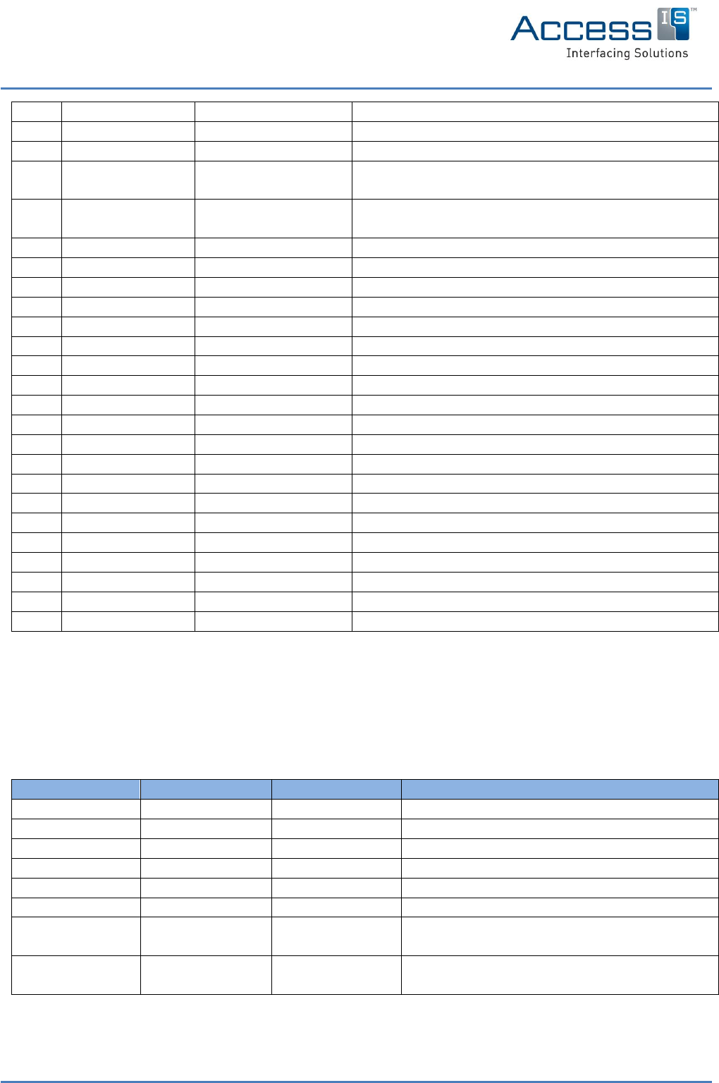
The following table shows the pinouts for the host connector.
Pin #
Signal Type
Signal
Description
1
Ground
GND
Ground signal
2
3V3 CMOS input
HOST_IFSEL_IO2
Host interface selection input – sampled during reset
3
3V3 CMOS input
HOST_IFSEL_IO1
Host interface selection input – sampled during reset
4
3V3 CMOS input
HOST_IFSEL_IO0
Host interface selection input – sampled during reset
5
Ground
GND
Ground signal
Contactless Payment Module (CPM)
Installation Manual
14
Installation manual - v0.1
6
3V3 CMOS I/O
EXT_TAMPER0
Security Tamper 0 signal
7
3V3 CMOS output
EMV_BEEPER
EMV Beeper signal
8
Ground
GND
Ground signal
9
Open collector
output/input
I2C0_SCL
External I2C interface – Not used
10
Open collector
output/input
I2C0_SDA
External I2C interface – Not used
11
Ground
GND
Ground signal
12
3V3 CMOS output
SPI0_CS2
External SPI interface slave select 2 – Not used
13
3V3 CMOS output
SPI0_CS0
External SPI interface slave select 0 – Not used
14
3V3 CMOS output
SPI0_SCK
External SPI interface clock – Not used
15
3V3 CMOS output
SPI0_MOSI
External SPI interface MOSI – Not used
16
3V3 CMOS input
SPI0_MISO
External SPI interface MISO – Not used
17
Power input
5V0
5V power input
18
USB data lines
USB D-
USB D- signal
19
USB data lines
USB D+
USB D+ signal
20
Power input
5V0
5V power input
21
3V3 CMOS output
EMV_LED3
EMV LED or Debug UART RTS signal, active low
22
3V3 CMOS input
EMV_LED2
EMV LED or Debug UART CTS signal, active low
23
3V3 CMOS input
EMV_LED1
EMV LED or Debug UART Receiver line
24
3V3 CMOS output
EMV_LED0
EMV LED or Debug UART Transmitter line
25
Power input
EXT_TAMPER1
Security Tamper1 signal
26
3V3 CMOS output
HOST_UART_RTS_n
Serial host UART RTS signal, active low
27
3V3 CMOS input
HOST_UART_CTS_n
Serial host UART CTS signal, active low
28
3V3 CMOS input
HOST_UART_RX
Serial host UART Receiver line
29
3V3 CMOS output
HOST_UART_TX
Serial host UART Transmitter line
30
Power input
5V0
5V power input
7.2. Host Interface Selection
The CPM module will select the host interface depending on the HOST_IFSEL_IOx signal values during reset. The
following table shows the different modes of operation based on the HOST_IFSEL_IOx signal.
HOST_IFSEL_IO2
HOST_IFSEL_IO1
HOST_IFSEL_IO0
Operating mode
0
0
0
USB mode
0
0
1
Serial mode
0
1
0
USB mode
0
1
1
USB mode
1
0
0
USB mode
1
0
1
USB mode
1
1
0
Serial Bootloader mode –Used for firmware
update
1
1
1
USB Bootloader mode – Used for firmware
update
Note that if any of the HOST_IFSEL_IO pins are left open, then the module reads that pin as HIGH.

Contactless Payment Module (CPM)
Installation Manual
15
Installation manual - v0.1
7.3. Serial Communication Settings
The module by default uses the following serial communication settings.
Parameter
Value
Baud Rate
115200
Data format
8 bits
Parity
None
Stop bits
1
Flow Control
RTS/CTS
Contactless Payment Module (CPM)
Installation Manual
16
Installation manual - v0.1
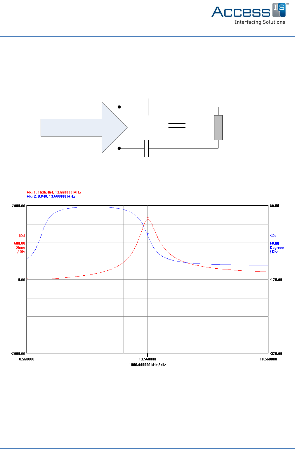
7.4. NFC Antenna
The NFC antenna is a simple LC circuit tuned to 13.56MHz. The following diagram show the circuit of the
antenna
LC2
C1a
Phase angle @13.56 MHz = 0 degree,
+/- 10 degree Antenna
loop
C1b
The Antenna is tuned to resonate at 13.56MHz with a phase angle tolerance of +/-10 degrees. The following
graph shows the impedance and phase for a typical antenna tuned to 13.56MHz.

Contactless Payment Module (CPM)
Installation Manual
17
Installation manual - v0.1
The following table provides information on the maximum and minimum values for the NFC antenna
parameters.
Parameter
Minimum
Typical
Maximum
Impedance @13.56MHz
800 Ohms
1500 Ohms
-
Phase @ 13.56MHz
-10 Degrees
0 Degrees
+10 Degrees
Antenna Coil inductance
700nH
1200nH
2000nH
Antenna Coil Q
30
50
100
Antenna Gain
0.6 (-2.21 dB)
0.7 (-1.54 dB)
0.8 (-0.96 dB)
Antenna maximum size
-
-
11cm x 15cm
The impedance at the PN5180 driver chip shall be typically 20 Ohm. The antenna impedance is adjusted to
achieve it.
7.5. Software Setup
Depending on the host interface selected, please refer USB or Serial software reference manual.

Contactless Payment Module (CPM)
Installation Manual
18
Installation manual - v0.1
8. Host Product Label
The host product using CPM module shall have the following text on a permanent label.
Contains FCC ID : ZERCPM01
The label should be on a visible location outside the enclosure of the product.
Contactless Payment Module (CPM)
Installation Manual
19
Installation manual - v0.1
9. Revision
Revision
Description
0.0
Initial version
0.1
Removed the module internal pictures
Confidential note removed