Accton Technology 2555WAG2 Dual Band Access Point User Manual WA6102 17
Accton Technology Corp Dual Band Access Point WA6102 17
Users Manual

www.edge-core.com
User Guide
WA6102X-2
2.4 GHz / 5 GHz
Wireless Access Point


User Guide
2.4 GHz / 5 GHz Wireless Access Point
IEEE 802.11g and 802.11a Dual-band Access Point
with 1 10/100BASE-TX (RJ-45) Port
WA6102X-2AG-17
F4.3.2.0 E012006-R01
149100033300E

i
COMPLIANCES
Federal Communication Commission Interference
Statement
This equipment has been tested and found to comply with the limits for a Class B
digital device, pursuant to Part 15 of the FCC Rules. These limits are designed to
provide reasonable protection against harmful interference in a residential
installation. This equipment generates, uses and can radiate radio frequency
energy and, if not installed and used in accordance with the instructions, may
cause harmful interference to radio communications. However, there is no
guarantee that interference will not occur in a particular installation. If this
equipment does cause harmful interference to radio or television reception, which
can be determined by turning the equipment off and on, the user is encouraged to
try to correct the interference by one of the following measures:
• Reorient or relocate the receiving antenna
• Increase the separation between the equipment and receiver
• Connect the equipment into an outlet on a circuit different from that to which the
receiver is connected
• Consult the dealer or an experienced radio/TV technician for help
FCC Caution: Any changes or modifications not expressly approved by the party
responsible for compliance could void the user's authority to operate this
equipment. This device complies with Part 15 of the FCC Rules. Operation is
subject to the following two conditions: (1) This device may not cause harmful
interference, and (2) this device must accept any interference received, including
interference that may cause undesired operation.
IMPORTANT NOTE:
FCC Radiation Exposure Statement
This equipment complies with FCC radiation exposure limits set forth for an
uncontrolled environment. This equipment should be installed and operated with a
minimum distance of 20 centimeters (8 inches) between the radiator and your
body. This transmitter must not be co-located or operating in conjunction with any
other antenna or transmitter.
Wireless 5 GHz Band Statements:
As the Access Point can operate in the 5150-5250 MHz frequency band it is
limited by the FCC, Industry Canada and some other countries to indoor use only
so as to reduce the potential for harmful interference to co-channel Mobile
Satellite systems.

COMPLIANCES
ii
High power radars are allocated as primary users (meaning they have priority) of
the 5250-5350 MHz and 5650-5850 MHz bands. These radars could cause
interference and /or damage to the access point when used in Canada.
The term “IC” before the radio certification number only signifies that Industry
Canada technical specifications were met.
Industry Canada - Class B
This digital apparatus does not exceed the Class B limits for radio noise emissions
from digital apparatus as set out in the interference-causing equipment standard
entitled “Digital Apparatus,” ICES-003 of Industry Canada.
Cet appareil numérique respecte les limites de bruits radioélectriques applicables
aux appareils numériques de Classe B prescrites dans la norme sur le matérial
brouilleur: “Appareils Numériques,” NMB-003 édictée par l’Industrie.
Japan VCCI Class B
Australia/New Zealand AS/NZS 4771
ACN 066 352010

C
OMPLIANCES
iii
EC Conformance Declaration
Marking by the above symbol indicates compliance with the Essential
Requirements of the R&TTE Directive of the European Union (1999/5/
EC). This equipment meets the following conformance standards:
• EN 60950-1 (IEC 60950-1) - Product Safety
• EN 301 893 - Technical requirements for 5 GHz radio equipment
• EN 300 328 - Technical requirements for 2.4 GHz radio equipment
• EN 301 489-1 / EN 301 489-17 - EMC requirements for radio equipment
Countries of Operation & Conditions of Use in the European
Community
This device is intended to be operated in all countries of the European
Community. Requirements for indoor vs. outdoor operation, license
requirements and allowed channels of operation apply in some countries
as described below:
Note: The user must use the configuration utility provided with this
product to ensure the channels of operation are in conformance
with the spectrum usage rules for European Community countries
as described below.
• This device requires that the user or installer properly enter the current
country of operation in the command line interface as described in the
user guide, before operating this device.
• This device will automatically limit the allowable channels determined
by the current country of operation. Incorrectly entering the country of
operation may result in illegal operation and may cause harmful
interference to other systems. The user is obligated to ensure the
device is operating according to the channel limitations, indoor/outdoor
restrictions and license requirements for each European Community
country as described in this document.
• This device employs a radar detection feature required for European
Community operation in the 5 GHz band. This feature is automatically
enabled when the country of operation is correctly configured for any
European Community country. The presence of nearby radar operation
may result in temporary interruption of operation of this device. The
radar detection feature will automatically restart operation on a channel
free of radar.

COMPLIANCES
iv
• The 5 GHz Turbo Mode feature is not allowed for operation in any
European Community country. The current setting for this feature is
found in the 5 GHz 802.11a Radio Settings Window as described in the
user guide.
• The 5 GHz radio's Auto Channel Select setting described in the user
guide must always remain enabled to ensure that automatic 5 GHz
channel selection complies with European requirements. The current
setting for this feature is found in the 5 GHz 802.11a Radio Settings
Window as described in the user guide.
• This device is restricted to indoor use when operated in the European
Community using the 5.15 - 5.35 GHz band: Channels 36, 40, 44, 48,
52, 56, 60, 64. See table below for allowed 5 GHz channels by country.
• This device may be operated indoors or outdoors in all countries of the
European Community using the 2.4 GHz band: Channels 1 - 13, except
where noted below.
- In Italy the end-user must apply for a license from the national
spectrum authority to operate this device outdoors.
- In Belgium outdoor operation is only permitted using the 2.46 -
2.4835 GHz band: Channel 13.
- In France outdoor operation is only permitted using the 2.4 - 2.454
GHz band: Channels 1 - 7.

C
OMPLIANCES
v
Operation Using 5 GHz Channels in the European
Community
The user/installer must use the provided configuration utility to check the
current channel of operation and make necessary configuration changes
to ensure operation occurs in conformance with European National
spectrum usage laws as described below and elsewhere in this
document.
Allowed 5GHz Channels in Each European Community Country
Allowed Frequency Bands Allowed Channel Numbers Countries
5.15 - 5.25 GHz* 36, 40, 44, 48 Austria, Belgium
5.15 - 5.35 GHz* 36, 40, 44, 48, 52, 56, 60, 64 France,
Switzerland,
Liechtenstein
5.15 - 5.35* & 5.470 - 5.725
GHz 36, 40, 44, 48, 52, 56, 60, 64,
100, 104, 108, 112, 116, 120,
124, 128, 132, 136, 140
Denmark, Finland,
Germany, Iceland,
Ireland, Italy,
Luxembourg,
Netherlands,
Norway, Portugal,
Spain, Sweden,
U.K.
5 GHz Operation Not
Allowed None Greece
* Outdoor operation is not allowed using 5.15-5.35 GHz bands (Channels 36 -
64).

COMPLIANCES
vi
Declaration of Conformity in Languages of the European
Community
English Hereby, SMC, declares that this Radio LAN device is in
compliance with the essential requirements and other relevant
provisions of Directive 1999/5/EC.
Finnish Valmistaja SMC vakuuttaa täten että Radio LAN device tyyppinen
laite on direktiivin 1999/5/EY oleellisten vaatimusten ja sitä
koskevien direktiivin muiden ehtojen mukainen.
Dutch Hierbij verklaart SMC dat het toestel Radio LAN device in
overeenstemming is met de essentiële eisen en de andere
relevante bepalingen van richtlijn 1999/5/EG
Bij deze SMC dat deze Radio LAN device voldoet aan de
essentiële eisen en aan de overige relevante bepalingen van
Richtlijn 1999/5/EC.
French Par la présente SMC déclare que l'appareil Radio LAN device est
conforme aux exigences essentielles et aux autres dispositions
pertinentes de la directive 1999/5/CE
Swedish Härmed intygar SMC att denna Radio LAN device står I
överensstämmelse med de väsentliga egenskapskrav och övriga
relevanta bestämmelser som framgår av direktiv 1999/5/EG.
Danish Undertegnede SMC erklærer herved, at følgende udstyr Radio
LAN device overholder de væsentlige krav og øvrige relevante
krav i direktiv 1999/5/EF
German Hiermit erklärt SMC, dass sich dieser/diese/dieses Radio LAN
device in Übereinstimmung mit den grundlegenden
Anforderungen und den anderen relevanten Vorschriften der
Richtlinie 1999/5/EG befindet". (BMWi)
Hiermit erklärt SMC die Übereinstimmung des Gerätes Radio
LAN device mit den grundlegenden Anforderungen und den
anderen relevanten Festlegungen der Richtlinie 1999/5/EG.
(Wien)
Greek με την παρουσα SMC δηλωνει οτι radio LAN device
συμμορφωνεται προσ τισ ουσιωδεισ απαιτησεισ και τισ λοιπεσ
σΧετικεσ διαταξεισ τησ οδηγιασ 1999/5/εκ
Italian Con la presente SMC dichiara che questo Radio LAN device è
conforme ai requisiti essenziali ed alle altre disposizioni pertinenti
stabilite dalla direttiva 1999/5/CE.

C
OMPLIANCES
vii
Safety Compliance
Power Cord Safety
Please read the following safety information carefully before installing the access
point:
WARNING: Installation and removal of the unit must be carried out by qualified
personnel only.
• The unit must be connected to an earthed (grounded) outlet to comply with
international safety standards.
• Do not connect the unit to an A.C. outlet (power supply) without an earth
(ground) connection.
• The appliance coupler (the connector to the unit and not the wall plug) must have
a configuration for mating with an EN 60320/IEC 320 appliance inlet.
• The socket outlet must be near to the unit and easily accessible. You can only
remove power from the unit by disconnecting the power cord from the outlet.
• This unit operates under SELV (Safety Extra Low Voltage) conditions according
to IEC 60950. The conditions are only maintained if the equipment to which it is
connected also operates under SELV conditions.
France and Peru only
This unit cannot be powered from IT† supplies. If your supplies are of IT type, this
unit must be powered by 230 V (2P+T) via an isolation transformer ratio 1:1, with
the secondary connection point labelled Neutral, connected directly to earth
(ground).
† Impédance à la terre
Spanish Por medio de la presente Manufacturer declara que el Radio LAN
device cumple con los requisitos esenciales y cualesquiera otras
disposiciones aplicables o exigibles de la Directiva 1999/5/CE
Portuguese Manufacturer declara que este Radio LAN device está conforme
com os requisitos essenciais e outras disposições da Directiva
1999/5/CE.

COMPLIANCES
viii
Important! Before making connections, make sure you have the correct cord set.
Check it (read the label on the cable) against the following:
Power Cord Set
U.S.A. and
Canada The cord set must be UL-approved and CSA certified.
The minimum specifications for the flexible cord are:
- No. 18 AWG - not longer than 2 meters, or 16 AWG.
- Type SV or SJ
- 3-conductor
The cord set must have a rated current capacity of at least
10 A
The attachment plug must be an earth-grounding type with
NEMA 5-15P (15 A, 125 V) or NEMA 6-15P (15 A, 250 V)
configuration.
Denmark The supply plug must comply with Section 107-2-D1,
Standard DK2-1a or DK2-5a.
Switzerland The supply plug must comply with SEV/ASE 1011.
U.K. The supply plug must comply with BS1363 (3-pin 13 A) and
be fitted with a 5 A fuse which complies with BS1362.
The mains cord must be <HAR> or <BASEC> marked and
be of type HO3VVF3GO.75 (minimum).
Europe The supply plug must comply with CEE7/7 (“SCHUKO”).
The mains cord must be <HAR> or <BASEC> marked and
be of type HO3VVF3GO.75 (minimum).
IEC-320 receptacle.

C
OMPLIANCES
ix
Veuillez lire à fond l'information de la sécurité suivante avant
d'installer le access point:
AVERTISSEMENT: L’installation et la dépose de ce groupe doivent être confiés à un
personnel qualifié.
• Ne branchez pas votre appareil sur une prise secteur (alimentation électrique)
lorsqu'il n'y a pas de connexion de mise à la terre (mise à la masse).
• Vous devez raccorder ce groupe à une sortie mise à la terre (mise à la masse) afin
de respecter les normes internationales de sécurité.
• Le coupleur d’appareil (le connecteur du groupe et non pas la prise murale) doit
respecter une configuration qui permet un branchement sur une entrée d’appareil
EN 60320/IEC 320.
• La prise secteur doit se trouver à proximité de l’appareil et son accès doit être
facile. Vous ne pouvez mettre l’appareil hors circuit qu’en débranchant son cordon
électrique au niveau de cette prise.
• L’appareil fonctionne à une tension extrêmement basse de sécurité qui est
conforme à la norme IEC 60950. Ces conditions ne sont maintenues que si
l’équipement auquel il est raccordé fonctionne dans les mêmes conditions.
France et Pérou uniquement:
Ce groupe ne peut pas être alimenté par un dispositif à impédance à la terre. Si vos
alimentations sont du type impédance à la terre, ce groupe doit être alimenté par
une tension de 230 V (2 P+T) par le biais d’un transformateur d’isolement à rapport
1:1, avec un point secondaire de connexion portant l’appellation Neutre et avec
raccordement direct à la terre (masse).
Cordon électrique - Il doit être agréé dans le pays d’utilisation
Etats-Unis et
Canada: Le cordon doit avoir reçu l’homologation des UL et un
certificat de la CSA.
Les spécifications minimales pour un cable flexible sont
AWG No. 18, ou AWG No. 16 pour un cable de longueur
inférieure à 2 mètres.
- type SV ou SJ
- 3 conducteurs
Le cordon doit être en mesure d’acheminer un courant
nominal d’au moins 10 A.
La prise femelle de branchement doit être du type à mise à
la terre (mise à la masse) et respecter la configuration NEMA
5-15P (15 A, 125 V) ou NEMA 6-15P (15 A, 250 V).
Danemark: La prise mâle d’alimentation doit respecter la section 107-2
D1 de la norme DK2 1a ou DK2 5a.

COMPLIANCES
x
Bitte unbedingt vor dem Einbauen des Access Point die folgenden
Sicherheitsanweisungen durchlesen (Germany):
WARNUNG: Die Installation und der Ausbau des Geräts darf nur durch
Fachpersonal erfolgen.
• Das Gerät sollte nicht an eine ungeerdete Wechselstromsteckdose
angeschlossen werden.
• Das Gerät muß an eine geerdete Steckdose angeschlossen werden, welche die
internationalen Sicherheitsnormen erfüllt.
• Der Gerätestecker (der Anschluß an das Gerät, nicht der
Wandsteckdosenstecker) muß einen gemäß EN 60320/IEC 320 konfigurierten
Geräteeingang haben.
• Die Netzsteckdose muß in der Nähe des Geräts und leicht zugänglich sein. Die
Stromversorgung des Geräts kann nur durch Herausziehen des
Gerätenetzkabels aus der Netzsteckdose unterbrochen werden.
• Der Betrieb dieses Geräts erfolgt unter den SELV-Bedingungen
(Sicherheitskleinstspannung) gemäß IEC 60950. Diese Bedingungen sind nur
gegeben, wenn auch die an das Gerät angeschlossenen Geräte unter
SELV-Bedingungen betrieben werden.
•
Suisse: La prise mâle d’alimentation doit respecter la norme SEV/
ASE 1011.
Europe La prise secteur doit être conforme aux normes CEE 7/7
(“SCHUKO”)
LE cordon secteur doit porter la mention <HAR> ou
<BASEC> et doit être de type HO3VVF3GO.75 (minimum).
Cordon électrique - Il doit être agréé dans le pays d’utilisation

C
OMPLIANCES
xi
Stromkabel. Dies muss von dem Land, in dem es benutzt wird geprüft werden:
U.S.A und
Kanada Der Cord muß das UL gepruft und war das CSA
beglaubigt.
Das Minimum spezifikation fur der Cord sind:
- Nu. 18 AWG - nicht mehr als 2 meter, oder 16 AWG.
- Der typ SV oder SJ
- 3-Leiter
Der Cord muß haben eine strombelastbarkeit aus
wenigstens 10 A
Dieser Stromstecker muß hat einer erdschluss mit der typ
NEMA 5-15P (15A, 125V) oder NEMA 6-15P (15A, 250V)
konfiguration.
Danemark Dieser Stromstecker muß die ebene 107-2-D1, der
standard DK2-1a oder DK2-5a Bestimmungen einhalten.
Schweiz Dieser Stromstecker muß die SEV/ASE
1011Bestimmungen einhalten.
Europe Das Netzkabel muß vom Typ HO3VVF3GO.75
(Mindestanforderung) sein und die Aufschrift <HAR> oder
<BASEC> tragen.
Der Netzstecker muß die Norm CEE 7/7 erfüllen
(”SCHUKO”).

COMPLIANCES
xii

xiii
Table of Contents
Chapter 1: Introduction 1-1
Package Checklist 1-2
Hardware Description 1-2
Component Description 1-3
Features and Benefits 1-5
Applications 1-6
System Defaults 1-6
Chapter 2: Hardware Installation 2-1
Chapter 3: External Antennas 3-1
Instalation Procedures 3-1
Chapter 4: Network Configuration 4-1
Network Topologies 4-2
Ad Hoc Wireless LAN (no Access Point) 4-2
Infrastructure Wireless LAN 4-3
Infrastructure Wireless LAN for Roaming Wireless PCs 4-4
Infrastructure Wireless Bridge 4-5
Infrastructure Wireless Repeater 4-6
Chapter 5: Initial Configuration 5-1
Initial Setup through the CLI 5-1
Required Connections 5-1
Initial Configuration Steps 5-2
Logging In 5-3
Chapter 6: System Configuration 6-1
Advanced Configuration 6-2
System Identification 6-3
TCP / IP Settings 6-5
RADIUS 6-7
SSH Settings 6-11
Authentication 6-12

xiv
Contents
Filter Control 6-17
VLAN 6-19
WDS Settings 6-21
AP Management 6-27
Administration 6-28
System Log 6-33
RSSI 6-37
SNMP 6-37
Configuring SNMP and Trap Message Parameters 6-38
Configuring SNMPv3 Users 6-42
Configuring SNMPv3 Trap Filters 6-44
Configuring SNMPv3 Targets 6-46
Radio Interface 6-48
Radio Settings A (802.11a) 6-49
Radio Settings G (802.11g) 6-63
Security 6-66
Status Information 6-84
Access Point Status 6-84
Station Status 6-87
Event Logs 6-90
Chapter 7: Command Line Interface 7-1
Using the Command Line Interface 7-1
Accessing the CLI 7-1
Console Connection 7-1
Telnet Connection 7-1
Entering Commands 7-2
Keywords and Arguments 7-2
Minimum Abbreviation 7-2
Command Completion 7-3
Getting Help on Commands 7-3
Partial Keyword Lookup 7-4
Negating the Effect of Commands 7-4
Using Command History 7-4
Understanding Command Modes 7-4
Exec Commands 7-5
Configuration Commands 7-5
Command Line Processing 7-6
Command Groups 7-6
General Commands 7-7
configure 7-8
end 7-8
exit 7-8
ping 7-9

xv
Contents
reset 7-10
show history 7-10
show line 7-11
System Management Commands 7-11
country 7-12
prompt 7-14
system name 7-14
username 7-15
password 7-15
ip ssh-server enable 7-16
ip ssh-server port 7-16
ip telnet-server enable 7-17
ip http port 7-17
ip http server 7-18
ip https port 7-18
ip https server 7-19
web-redirect 7-20
APmgmtIP 7-21
APmgmtUI 7-22
show apmanagement 7-22
show system 7-23
show version 7-24
show config 7-24
show hardware 7-28
System Logging Commands 7-28
logging on 7-29
logging host 7-29
logging console 7-30
logging level 7-30
logging facility-type 7-31
logging clear 7-32
show logging 7-32
show event-log 7-33
System Clock Commands 7-33
sntp-server ip 7-34
sntp-server enable 7-34
sntp-server date-time 7-35
sntp-server daylight-saving 7-36
sntp-server timezone 7-36
show sntp 7-37
DHCP Relay Commands 7-38
dhcp-relay enable 7-38
dhcp-relay 7-39
show dhcp-relay 7-39
SNMP Commands 7-40

xvi
Contents
snmp-server community 7-41
snmp-server contact 7-41
snmp-server location 7-42
snmp-server enable server 7-42
snmp-server host 7-43
snmp-server trap 7-44
snmp-server engine-id 7-45
snmp-server user 7-46
snmp-server targets 7-48
snmp-server filter 7-49
snmp-server filter-assignments 7-50
show snmp groups 7-50
show snmp users 7-51
show snmp group-assignments 7-51
show snmp target 7-52
show snmp filter 7-52
show snmp filter-assignments 7-53
show snmp 7-54
Flash/File Commands 7-55
bootfile 7-55
copy 7-56
delete 7-57
dir 7-58
show bootfile 7-58
RADIUS Client 7-59
radius-server address 7-59
radius-server port 7-60
radius-server key 7-60
radius-server retransmit 7-61
radius-server timeout 7-61
radius-server port-accounting 7-62
radius-server timeout-interim 7-62
radius-server radius-mac-format 7-63
radius-server vlan-format 7-63
show radius 7-64
802.1X Authentication 7-65
802.1x 7-65
802.1x broadcast-key-refresh-rate 7-66
802.1x session-key-refresh-rate 7-67
802.1x session-timeout 7-67
802.1x-supplicant enable 7-68
802.1x-supplicant user 7-68
show authentication 7-69
MAC Address Authentication 7-70
address filter default 7-70

xvii
Contents
address filter entry 7-71
address filter delete 7-71
mac-authentication server 7-72
mac-authentication session-timeout 7-72
Filtering Commands 7-73
filter local-bridge 7-73
filter ap-manage 7-74
filter ethernet-type enable 7-74
filter ethernet-type protocol 7-75
show filters 7-76
WDS Bridge Commands 7-76
bridge role (WDS) 7-77
bridge-link parent 7-77
bridge-link child 7-78
bridge dynamic-entry age-time 7-78
show bridge aging-time 7-79
show bridge filter-entry 7-80
show bridge link 7-80
Spanning Tree Commands 7-82
bridge stp enable 7-82
bridge stp forwarding-delay 7-83
bridge stp hello-time 7-83
bridge stp max-age 7-84
bridge stp priority 7-84
bridge-link path-cost 7-85
bridge-link port-priority 7-85
show bridge stp 7-86
Ethernet Interface Commands 7-87
interface ethernet 7-87
dns server 7-88
ip address 7-88
ip dhcp 7-89
speed-duplex 7-90
shutdown 7-91
show interface ethernet 7-91
Wireless Interface Commands 7-92
interface wireless 7-94
vap 7-94
speed 7-95
turbo 7-95
multicast-data-rate 7-96
channel 7-96
transmit-power 7-97
radio-mode 7-98
preamble 7-98

xviii
Contents
antenna control 7-99
antenna id 7-100
antenna location 7-100
beacon-interval 7-101
dtim-period 7-101
fragmentation-length 7-102
rts-threshold 7-103
super-a 7-104
super-g 7-104
description 7-105
ssid 7-105
closed-system 7-106
max-association 7-106
assoc-timeout-interval 7-107
auth-timeout-value 7-107
shutdown 7-107
show interface wireless 7-109
show station 7-110
Rogue AP Detection Commands 7-111
rogue-ap enable 7-111
rogue-ap authenticate 7-112
rogue-ap duration 7-113
rogue-ap interval 7-113
rogue-ap scan 7-114
show rogue-ap 7-115
Wireless Security Commands 7-115
auth 7-116
encryption 7-118
key 7-119
transmit-key 7-120
cipher-suite 7-121
mic_mode 7-122
wpa-pre-shared-key 7-123
pmksa-lifetime 7-123
pre-authentication 7-124
Link Integrity Commands 7-125
link-integrity ping-detect 7-126
link-integrity ping-host 7-126
link-integrity ping-interval 7-127
link-integrity ping-fail-retry 7-127
link-integrity ethernet-detect 7-127
show link-integrity 7-128
IAPP Commands 7-129
iapp 7-129
VLAN Commands 7-130

xix
Contents
vlan 7-130
management-vlanid 7-131
vlan-id 7-131
WMM Commands 7-132
wmm 7-133
wmm-acknowledge-policy 7-133
wmmparam 7-134
Appendix A: Troubleshooting A-1
Appendix B: Cables and Pinouts B-1
Twisted-Pair Cable Assignments B-1
10/100BASE-TX Pin Assignments B-1
Straight-Through Wiring B-2
Crossover Wiring B-3
Console Port Pin Assignments B-3
Wiring Map for Serial Cable B-4
Appendix C: Specifications C-1
General Specifications C-1
Sensitivity C-4
Transmit Power C-5
Operating Range C-6
Glossary
Index

xx
Contents

1-1
Chapter 1: Introduction
The 2.4 GHz/5 GHz Wireless Access Point is an IEEE 802.11a/g access point that
provides transparent, wireless high-speed data communications between the wired
LAN and fixed or mobile devices equipped with an 802.11a, 802.11b, or 802.11g
wireless adapter.
This solution offers fast, reliable wireless connectivity with considerable cost savings
over wired LANs (which include long-term maintenance overhead for cabling). Using
802.11a and 802.11g technology, this access point can easily replace a 10 Mbps
Ethernet connection or seamlessly integrate into a 10/100 Mbps Ethernet LAN.
The access point supports up to eight Virtual Access Points per physical radio
interface, that is eight on the 802.11a radio and eight on the 802.11g radio. This
allows traffic to be separated for different user groups using an access point that
services one area. For each VAP, different security settings, VLAN assignments, and
other parameters can be applied.
Each radio interface on the access point can operate in one of four modes:
• Access Point – Providing conectivity to wireless clients in the service area.
• Repeater – Providing an extended link to a remote access point from the wired
LAN. In this mode, the access point does not have a cable connection to the wired
Ethernet LAN.
• Bridge – Providing links to access points operating in “Bridge” or “Root Bridge”
mode and thereby connecting other wired LAN segments.
• Root Bridge – Providing links to other access points operating in “Bridge” mode
and thereby connecting other wired LAN segments. Only one unit in the wireless
bridge network can be set to “Root Bridge” mode.
In addition, the access point offers full network management capabilities through an
easy to configure web interface, a command line interface for initial configuration
and troubleshooting, and support for Simple Network Management Protocol tools.
Radio Characteristics – The IEEE 802.11a/g standard uses a radio modulation
technique known as Orthogonal Frequency Division Multiplexing (OFDM), and a
shared collision domain (CSMA/CA). It operates at the 5 GHz Unlicensed National
Information Infrastructure (UNII) band for connections to 802.11a clients, and at 2.4
GHz for connections to 802.11g clients.
IEEE 802.11g includes backward compatibility with the IEEE 802.11b standard.
IEEE 802.11b also operates at 2.4 GHz, but uses Direct Sequence Spread
Spectrum (DSSS) and Complementary Code Keying (CCK) modulation technology
to achieve a communication rate of up to 11 Mbps.
The access point supports a 54 Mbps half-duplex connection to Ethernet networks
for each active channel (or up to 108 Mbps when using turbo mode on the 802.11a
interface).
Introduction
1-2
1
Package Checklist
The 2.4 GHz/5 GHz Wireless Access Point package includes:
• One 2.4 GHz/5 GHz Wireless Access Point
• One Category 5 network cable
• One RS-232 console cable
• One AC power adapter and power cord
• Four rubber feet
• User Guide CD
Inform your dealer if there are any incorrect, missing or damaged parts. If possible,
retain the carton, including the original packing materials. Use them again to repack
the product in case there is a need to return it.
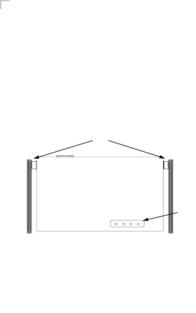
Hardware Description
Top Panel
PWR Link 11a 11g
LED
Indicators
Antennas
Hardware Description
1-3
1
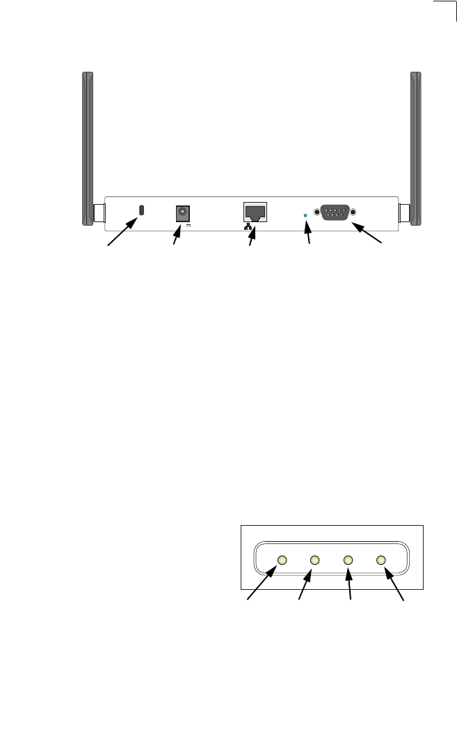
Rear Panel
Component Description
Antennas
The access point includes integrated diversity antennas for wireless
communications. A diversity antenna system uses two identical antennas to receive
and transmit signals, helping to avoid multipath fading effects. When receiving, the
access point checks both antennas and selects the one with the strongest signal.
When transmitting, it will continue to use the antenna previously selected for
receiving. The access point never transmits from both antennas at the same time.
The antennas transmit the outgoing signal as a toroidal sphere (doughnut shaped),
with the coverage extending most in a direction perpendicular to the antenna. The
antenna should be adjusted to an angle that provides the appropriate coverage for
the service area. For further information, see “Positioning the Antennas” on 2-2.
LED Indicators
The access point includes four status LED
indicators, as described in the following
figure and table.
Lock ConsolePOE In ResetDC 5V
Security Slot Console
Port
RJ-45 Port,
PoE Connector Reset
Button
5 VDC
Power Socket
PWR Link 11a 11g
Power 802.11a
Wireless
Link/Activity
Ethernet
Link/Activity 802.11b/g
Wireless
Link/Activity

Introduction
1-4
1
Security Slot
The access point includes a Kensington security slot on the rear panel. You can
prevent unauthorized removal of the access point by wrapping the Kensington
security cable (not provided) around an unmovable object, inserting the lock into the
slot, and turning the key.
Console Port
This port is used to connect a console device to the access point through a serial
cable. This connection is described under “Console Port Pin Assignments” on page
B-3. The console device can be a PC or workstation running a VT-100 terminal
emulator, or a VT-100 terminal.
Ethernet Port
The access point has one 10BASE-T/100BASE-TX RJ-45 port that can be attached
directly to 10BASE-T/100BASE-TX LAN segments. These segments must conform
to the IEEE 802.3 or 802.3u specifications.
This port uses an MDI (i.e., internal straight-through) pin configuration. You can
therefore use straight-through twisted-pair cable to connect this port to most network
interconnection devices such as a switch or router that provide MDI-X ports.
However, when connecting the access point to a workstation or other device that
does not have MDI-X ports, you must use crossover twisted-pair cable.
The access point appears as an Ethernet node and performs a bridging function by
moving packets from the wired LAN to remote workstations on the wireless
infrastructure.
LED Status Description
PWR On Indicates that the system is working normally.
Flashing Indicates running a self-test or loading the software program.
Flashing (Prolonged) Indicates system errors.
Link On Indicates a valid 10/100 Mbps Ethernet cable link.
Flashing Indicates that the access point is transmitting or receiving data
on a 10/100 Mbps Ethernet LAN. Flashing rate is proportional
to network activity.
11a On Indicates that the 802.11a radio is enabled.
Flashing Indicates that the access point is transmitting or receiving data
through wireless links. Flashing rate is proportional to network
activity.
Off Indicates that the 802.11a radio is disabled.
11g On Indicates that the 802.11b/g radio is enabled.
Flashing Indicates that the access point is transmitting or receiving data
through wireless links. Flashing rate is proportional to network
activity.
Off Indicates that the 802.11b/g radio is disabled.

Features and Benefits
1-5
1
Note: The RJ-45 port also supports Power over Ethernet (PoE) based on the IEEE
802.3af standard. Refer to the description for the “Power Connector” for
information on supplying power to the access point’s network port from a network
device, such as a switch, that provides Power over Ethernet (PoE).
Reset Button
This button is used to reset the access point or restore the factory default
configuration. If you hold down the button for less than 5 seconds, the access point
will perform a hardware reset. If you hold down the button for 5 seconds or more,
any configuration changes you may have made are removed, and the factory default
configuration is restored to the access point.
Power Connector
The access point does not have a power switch. It is powered on when connected to
the AC power adapter, and the power adapter is connected to a power source. The
power adapter automatically adjusts to any voltage between 100-240 volts at 50 or
60 Hz. No voltage range settings are required.
The access point may also receive Power over Ethernet (PoE) from a switch or
other network device that supplies power over the network cable based on the IEEE
802.3af standard.
Note that if the access point is connected to a PoE source device and also
connected to a local power source through the AC power adapter, PoE will be
disabled.
Features and Benefits
• Local network connection via 10/100 Mbps Ethernet ports or 54 Mbps wireless
interface (supporting up to 128 mobile users)
• IEEE 802.11a, 802.11b, and 802.11g compliant
• Interoperable with multiple vendors based on the IEEE 802.11f protocol
• Advanced security through 64/128/152-bit Wired Equivalent Protection (WEP)
encryption, IEEE 802.1X authentication via a RADIUS server, Wi-Fi Protected
Access (WPA), and MAC address filtering features to protect your sensitive data
and authenticate only authorized users to your network
• Provides seamless roaming within the IEEE 802.11a, 802.11b and 802.11g WLAN
environment
• Scans all available channels and selects the best channel for each client based on
the signal-to-noise ratio

Introduction
1-6
1
Applications
Wireless network products offer a high speed, reliable, cost-effective solution for
wireless Ethernet client access to the network in applications such as:
• Remote access to corporate network information –
E-mail, file transfer, and terminal emulation.
• Difficult-to-wire environments –
Historical or old buildings, asbestos installations, and open areas where wiring is
difficult to employ.
• Frequently changing environments –
Retailers, manufacturers, and banks that frequently rearrange the workplace or
change location.
• Temporary LANs for special projects or peak times –
Trade shows, exhibitions and construction sites that need temporary setup for a
short time period. Retailers, airline and shipping companies that need additional
workstations for a peak period. Auditors who require workgroups at customer
sites.
• Access to databases for mobile workers –
Doctors, nurses, retailers, or white-collar workers who need access to databases
while being mobile in a hospital, retail store, or an office campus.
• SOHO users –
SOHO (Small Office and Home Office) users who need easy and quick installation
of a small computer network.
System Defaults
The following table lists some of the access point’s basic system defaults. To reset
the access point defaults, use the CLI command “reset configuration” from the Exec
level prompt.
Table 1-1. System Defaults
Feature Parameter Default
Identification System Name SMC
Administration User Name admin
Password null
General HTTP Server Enabled
HTTP Server Port 80
HTTPS Server Enabled
HTTPS Server Port 443
Web Redirect Disabled

System Defaults
1-7
1
TCP/IP DHCP Enabled
IP Address 192.168.1.1
Subnet Mask 255.255.255.0
Default Gateway 0.0.0.0
Primary DNS IP 0.0.0.0
Secondary DNS IP 0.0.0.0
RADIUS (Primary and
Secondary) IP Address 0.0.0.0
Port 1812
Key DEFAULT
Timeout 5 seconds
Retransmit attempts 3
Accounting Port 0 (Disabled)
Interim Update Timeout 3600 seconds
SSH Server Status Enabled
Server Port 22
PPPoE PPPoE Status Disabled
MAC Authentication MAC Disabled
Authentication Session Timeout 0 minutes (disabled)
Local MAC System Default Allowed
Local MAC Permission Allowed
802.1X Authentication Status Disabled
Broadcast Key Refresh 0 minutes (disabled)
Session Key Refresh 0 minutes (disabled)
Reauthentication Refresh Rate 0 seconds (disabled)
Supplicant Disabled
VLAN Management VLAN ID 1
VLAN ID (VAP Interface) 1
VLAN Tag Support Disabled
QoS QoS Mode Off
SVP (SpectraLink Voice Priority) Disabled
Table 1-1. System Defaults
Feature Parameter Default

Introduction
1-8
1
Filter Control Local Bridge Disabled
AP Management Enabled
Ethernet Type Disabled
SNMP Status Enabled
Location null
Contact null
Community (Read Only) Public
Community
(Read/Write) Private
Traps Enabled
Trap Destination (1-4) Disabled
Trap Destination IPAddress null
Trap Destination Community
Name Public
SNMP v3 Groups RO
RWAuth
RWPriv
SNMP v3 Users none
System Logging Syslog Disabled
Logging Host Disabled
Logging Console Disabled
IP Address / Host Name 0.0.0.0
Logging Level Informational
Logging Facility Type 16
System Clock SNTP Server Status Enabled
SNTP Server 1 IP 137.92.140.80
SNTP Server 2 IP 192.43.244.18
Date and Time 00:00, Jan 1, 1970 (when there is no time
server)
Daylight Saving Time Disabled
Time Zone GMT-5 (Eastern Time, US and Canada)
Ethernet Interface Speed and Duplex Auto
Table 1-1. System Defaults
Feature Parameter Default

System Defaults
1-9
1
Wireless Interface
802.11a IAPP Enabled
SSID VAP_TEST_11A (0 to 7)
Turbo Mode Disabled
Status Disabled
Auto Channel Select Enabled
Closed System Disabled
Transmit Power Full
Max Station Data Rate 54 Mbps
Multicast Data Rate 6 Mbps
Beacon Interval 100 TUs
Data Beacon Rate (DTIM Interval) 1 beacon
RTS Threshold 2347 bytes
Association Timeout Interval 30 minutes
Authentication Timeout Interval 60 minutes
Rogue AP Detection Disabled
Antenna Control Method Diversity
Antenna ID 0x0000
Antenna Location Indoor
Wireless Security
802.11a Authentication Type Open System
Data Encryption Disabled
WEP Key Length 128 bits
WEP Key Type Hexadecimal
WEP Transmit Key Number 1
WEP Keys null
WPA Configuration Mode WEP Only (Disabled)
WPA Key Management WPA Pre-shared Key
WPA PSK Type Alphanumeric
Multicast Cipher WEP
Table 1-1. System Defaults
Feature Parameter Default

Introduction
1-10
1
Wireless Interface
802.11b/g IAPP Enabled
SSID VAP_TEST_11G (0 to 7)
Radio Mode b+g
Status Disabled
Auto Channel Select Enabled
Closed System Disabled
Transmit Power Full
Max Station Data Rate 54 Mbps
Multicast Data Rate 5.5 Mbps
Preamble Length Long
Beacon Interval 100 TUs
Data Beacon Rate (DTIM Interval) 1 beacon
RTS Threshold 2347 bytes
Association Timeout Interval 30 minutes
Authentication Timeout Interval 60 minutes
Rogue AP Detection Disabled
Antenna Control Method Diversity
Antenna ID 0x0000
Antenna Location Indoor
Wireless Security
802.11b/g Authentication Type Open System
Data Encryption Disabled
WEP Key Length 128 bits
WEP Key Type Hexadecimal
WEP Transmit Key Number 1
WEP Keys null
WPA Configuration Mode WEP Only (Disabled)
WPA Key Management WPA Pre-shared Key
WPA PSK Type Alphanumeric
Multicast Cipher WEP
Table 1-1. System Defaults
Feature Parameter Default

System Defaults
1-11
1
Link Integrity Status Disabled
Ping Interval 30 seconds
Fail Retry Count 6
Table 1-1. System Defaults
Feature Parameter Default

Introduction
1-12
1
2-1
Chapter 2: Hardware Installation
1. Select a Site – Choose a proper place for the access point. In general, the best
location is at the center of your wireless coverage area, within line of sight of all
wireless devices. Try to place the access point in a position that can best cover
its Basic Service Set (refer to “Infrastructure Wireless LAN” on page 4-3). For
optimum performance, consider these points:
• Mount the access point as high as possible above any obstructions in the
coverage area.
• Avoid mounting next to or near building support columns or other obstructions
that may cause reduced signal or null zones in parts of the coverage area.
• Mount away from any signal absorbing or reflecting structures (such as those
containing metal).
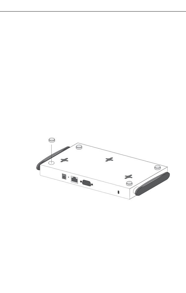
2. Mount the Access Point – The access point can be mounted on any
horizontal surface.
Mounting on a horizontal surface – To keep the access point from sliding on the
surface, attach the four rubber feet provided in the accessory kit to the marked
circles on the bottom of the access point.
Lock the Access Point in Place – To prevent unauthorized removal of the
access point, you can use a Kensington Slim MicroSaver security cable (not
included) to attach the access point to a fixed object.
3. Connect the Power Cord – Connect the power adapter to the access point,
and the power cord to an AC power outlet.
Otherwise, the access point can derive its operating power directly from the
RJ-45 port when connected to a device that provides IEEE 802.3af compliant
Power over Ethernet (PoE).
Note: If the access point is connected to both a PoE source device and an AC power
source, PoE will be disabled.
Caution: Use ONLY the power adapter supplied with this access point. Otherwise, the
product may be damaged.

Hardware Installation
2-2
2
4. Observe the Self Test – When you power on the access point, verify that the
PWR indicator stops flashing and remains on, and that the other indicators start
functioning as described under “LED Indicators” on page 1-3. If the PWR LED
does not stop flashing, the self test has not completed correctly. Refer to
“Troubleshooting” on page A-1.
5. Connect the Ethernet Cable – The access point can be wired to a 10/100
Mbps Ethernet through a network device such as a hub or a switch. Connect
your network to the RJ-45 port on the back panel with category 3, 4, or 5 UTP
Ethernet cable. When the access point and the connected device are powered
on, the Ethernet Link LED should light indicating a valid network connection. If
this LED fails to turn on refer to “Troubleshooting” on page A-1.
Note: The RJ-45 port on the access point uses an MDI pin configuration, so you must
use straight-through cable for network connections to switches that only have
MDI-X ports, and crossover cable for network connections to PCs, servers or
other devices that only have MDI ports. However, if the connected device
supports auto-MDI/MDI-X operation, you can use either straight-through or
crossover cable.
6. Position the Antennas – Each antenna emits a radiation pattern that is
toroidal (doughnut shaped), with the coverage extending most in the direction
perpendicular to the antenna. Therefore, the antennas should be oriented so
that the radio coverage pattern fills the intended horizontal space. Also, the
diversity antennas should both be positioned along the same axes, providing
the same coverage area. For example, if the access point is mounted on a
horizontal surface, both antennas should be positioned pointing vertically up to
provide optimum coverage.
7. Connect the Console Port – Connect the console cable (included) to the
RS-232 console port for accessing the command-line interface. You can
manage the access point using the console port (Chapter 6), the web interface
(Chapter 5), or SNMP management software such as HP’s OpenView.

3-1
Chapter 3: External Antennas
The SMC WA6102X-2AG provides a variety of external antenna options for
extending the radio range and shaping the coverge area. These antennas offer a
number of different mounting locations, including indoor or outdoor, wall,
ceiling, or radio mast.
This chapter shows you how to install an external antenna for your
WA6102X-2AG.
Only the SMC antennas listed in this guide are permitted to be connected to the
WA6102X-2AG. You must use the appropriate antennas, cables, and where
applicable, surge arrestors, for your given region. You are responsible for
verifying local regulations or legislation that may impose restrictions on the use
of specific antenna and cable combinations. For this reason, SMC recommends
that you consult with a professional installer who is trained in RF installation
and knowledgeable in the local regulations prior to connecting an external
antenna to your wireless radio product. It is the responsibility of the end user to
ensure that the antenna installation complies with the local radio regulations.
Instalation Procedures
Follow these steps to install an external antenna and connect it to the
WA6102X-2AG.
Caution: Never mount the access point outdoors to be near an external antenna.
The access point must always be installed indoors.
1. Plan the Installation
•Pigtail Cables - Use the coax pigtail cable attached to the antenna to connect
to the access point. Because most pigtail cables are a relatively short length
(83 cm or 33 inches), be sure to find a suitable mounting position for the
antenna that is not too far from the access point. If an extension cable is
required, please contact a professional installer who is trained in RF
installation and knowledgeable in the local regulations.
•Installation Location - Plan the antenna’s position and orientation.
Warning: The radiated output power of this device is below the FCC radio
exposure limits. Nevertheless, the device should be used in such a
manner that the potential for human contact during normal operation
is minimized. To avoid the possibility of exceeding the FCC radio
frequency exposure limits, human proximity to the antennas should
not be less than 20 cm (8 inches) during normal operation.

External Antennas
3-2
3
Consider these points:
• Use the antenna’s mounting bracket or other hardware, if included.
• For optimum performance, mount antennas as high as possible above any
obstructions, and away from any signal absorbing or reflecting structures
(such as those containing metal)
• Be sure there are no other radio antennas mounted within 2 m (6 ft).
• Consider the antenna’s radio coverage pattern so that it can properly cover
the intended service area.
•Omnidirectional Antennas - Consider these factors when selecting a
location for these antennas:
• Always mount the antenna in a vertical orientation so that the radio
coverage pattern fills the intended horizontal space.
• For optimum coverage, mount the antenna at the center of the area with a
line-of-sight path to all points within the area.
• Avoid mounting next to or near building support columns or other
obstructions that may cause reduced signal or null zones in parts of the
coverage area.
• When mounting outdoors using a mast, make sure that the antenna extends
beyond the top of the mast.
•Directional Antennas - Consider these factors when selecting a location for
these antennas:
• For optimum coverage, mount the antenna above any obstructions,
directed at the center of the coverage area sector.
• High-gain directional antennas provide a flattened radio coverage pattern
in the horizontal plane. Use the tilting or articulated mounts to point the
antennas towards the coverage area.
•Outdoor Installation - When installing an antenna outdoors, be sure to
consider these additional factors:
• Always place the antenna away from power and telephone lines
• Make sure that the antenna, any supporting structure, and cables are all
properly grounded.
• For lightning protection, consider using a lightning arrestor immediately
before the cable enters the building.
Warning: Never install an antenna or construct a radio mast near overhead
power lines.
2. Mount the Antenna
Install the antenna in its planned location using the brackets, clips, or other hardware
included in the antenna package.
Refer to documentation included with the antenna for specific information and
installation instructions.

Instalation Procedures
3-3
3
3. Connect Pigtail Cables to the Access Point
Use the pigtail cables that are attached to the antenna, or are included in the
antenna package. If an extension cable is required, please contact a professional
installer who is trained in RF installation and knowledgeable in the local regulations.
Note that diversity antennas have two pigtail cables. A diversity antenna includes
two internal antenna elements that are identical. Both antenna pigtail cables must be
connected to the access point for correct operation.
Other non-diversity antennas, which have only one pigtail cable, attach to the
access point’s right antenna connector. The access point’s right antenna is the one
on the side closest to the LED indicators. When using a non-diversity antenna, a
50-ohm terminator (included with the antenna) must be connected to the access
point’s left antenna connector.
To connect pigtail cables to the access point, follow these steps:
1. Disable the access point radio using the web browser interface, CLI, or SNMP.
2. Remove power to the access point.
3. Remove both of the access point’s antennas by unscrewing them at their base.
4. For diversity antennas, connect the antenna pigtail cables to the exposed
Reverse SMA connectors on both sides of the access point.
For non-diversity antennas, be sure to connect the single pigtail cable to the
Reverse SMA connector on the access point’s right side. When using a
non-diversity antenna, you must also connect the 50-ohm terminator
(5092-0933), included with the antenna, to the access point’s left-side Reverse
SMA connector.
Right antenna
Unscrew antenna
to remove

External Antennas
3-4
3
5. Reconnect power to the access point.
Note: Before enabling the radio with an external antenna attached, be sure to first
configure the access point’s antenna mode and transmit power settings.
Antenna pigtail cable
Screw onto access point’s

4-1
Chapter 4: Network Configuration
Wireless networks support a stand-alone configuration as well as an integrated
configuration with 10/100 Mbps Ethernet LANs. The 2.4 GHz/5 GHz Wireless
Access Point also provides repeater and bridging services that can be configured
independently on either the 5 GHz or 2.4 GHz radio interfaces.
Access points can be deployed to support wireless clients and connect wired LANs
in the following configurations:
• Ad hoc for departmental, SOHO or enterprise LANs
• Infrastructure for wireless LANs
• Infrastructure wireless LAN for roaming wireless PCs
• Infrastructure wireless bridge to connect wired LANs
• Infrastructure wireless repeater for extended range
The 802.11b and 802.11g frequency band which operates at 2.4 GHz can easily
encounter interference from other 2.4 GHz devices, such as other 802.11b or g
wireless devices, cordless phones and microwave ovens. If you experience poor
wireless LAN performance, try the following measures:
• Limit any possible sources of radio interference within the service area
• Increase the distance between neighboring access points
• Decrease the signal strength of neighboring access points
• Increase the channel separation of neighboring access points (e.g. up to 5
channels of separation for 802.11b and 802.11g)
Network Configuration
4-2
4
Network Topologies
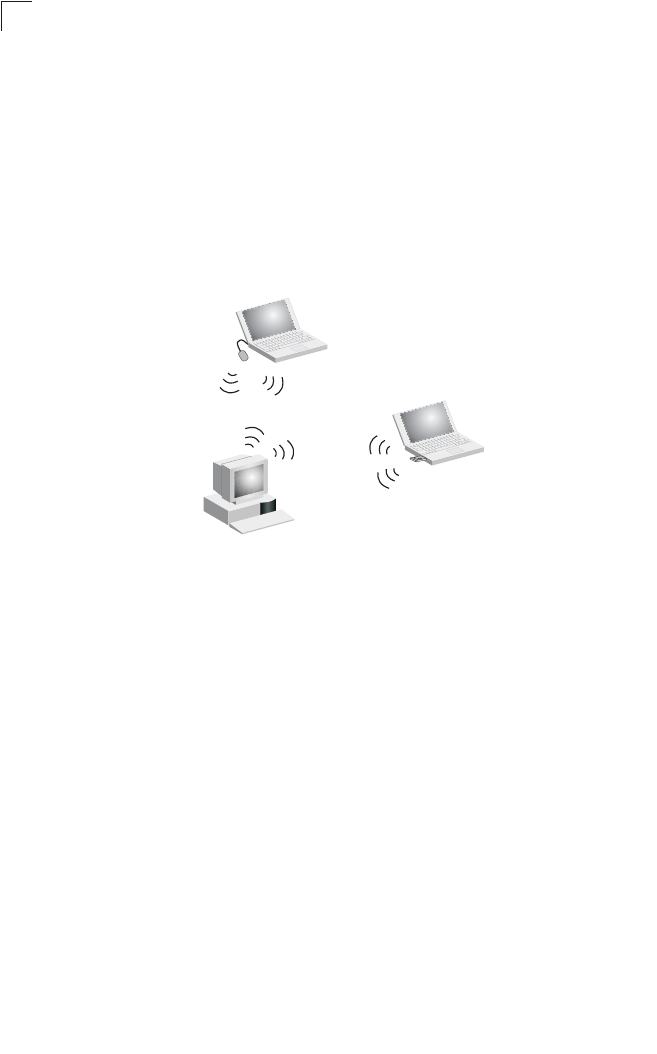
Ad Hoc Wireless LAN (no Access Point)
An ad hoc wireless LAN consists of a group of computers, each equipped with a
wireless adapter, connected via radio signals as an independent wireless LAN.
Computers in a specific ad hoc wireless LAN must therefore be configured to the
same radio channel. An ad hoc wireless LAN can be used for a branch office or
SOHO operation.
Ad Hoc Wireless LAN
Notebook with
Wireless USB Adapter
Notebook with
Wireless PC Card
PC with Wireless
PCI Ada
p
ter
Network Topologies
4-3
4
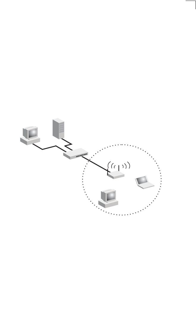
Infrastructure Wireless LAN
The access point also provides access to a wired LAN for wireless workstations. An
integrated wired/wireless LAN is called an Infrastructure configuration. A Basic
Service Set (BSS) consists of a group of wireless PC users, and an access point
that is directly connected to the wired LAN. Each wireless PC in this BSS can talk to
any computer in its wireless group via a radio link, or access other computers or
network resources in the wired LAN infrastructure via the access point.
The infrastructure configuration not only extends the accessibility of wireless PCs to
the wired LAN, but also increases the effective wireless transmission range for
wireless PCs by passing their signal through one or more access points.
A wireless infrastructure can be used for access to a central database, or for
connection between mobile workers, as shown in the following figure.
Server
Switch
Desktop PC
Access Point
Wired LAN Extension
to Wireless Clients
Desktop PC
Notebook PC
Network Configuration
4-4
4
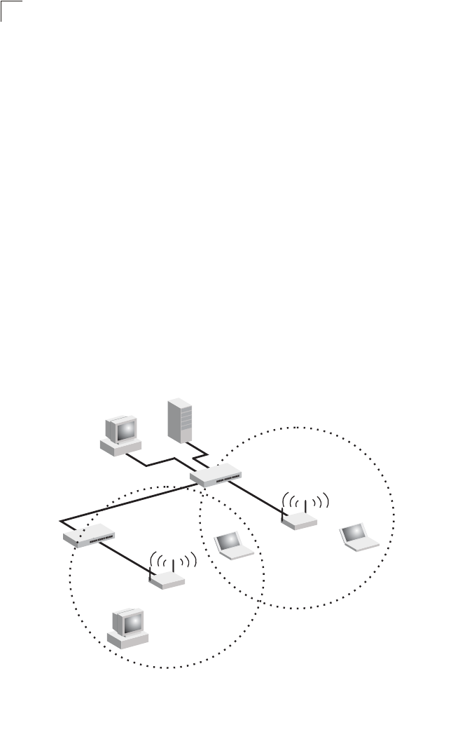
Infrastructure Wireless LAN for Roaming Wireless PCs
The Basic Service Set (BSS) defines the communications domain for each access
point and its associated wireless clients. The BSS ID is a 48-bit binary number
based on the access point’s wireless MAC address, and is set automatically and
transparently as clients associate with the access point. The BSS ID is used in
frames sent between the access point and its clients to identify traffic in the service
area.
The BSS ID is only set by the access point, never by its clients. The clients only
need to set the Service Set Identifier (SSID) that identifies the service set provided
by one or more access points. The SSID can be manually configured by the clients,
can be detected in an access point’s beacon, or can be obtained by querying for the
identity of the nearest access point. For clients that do not need to roam, set the
SSID for the wireless card to that used by the access point to which you want to
connect.
A wireless infrastructure can also support roaming for mobile workers. More than
one access point can be configured to create an Extended Service Set (ESS). By
placing the access points so that a continuous coverage area is created, wireless
users within this ESS can roam freely. All wireless network cards and adapters and
wireless access points within a specific ESS must be configured with the same
SSID.
<BSS 2>
<ESS>
<BSS 1>
Server
Switch
Desktop PC
Access Point
Seamless Roaming
Between Access Points
Desktop PC
Notebook PC
Access Point
Notebook PC
Switch

Network Topologies
4-5
4
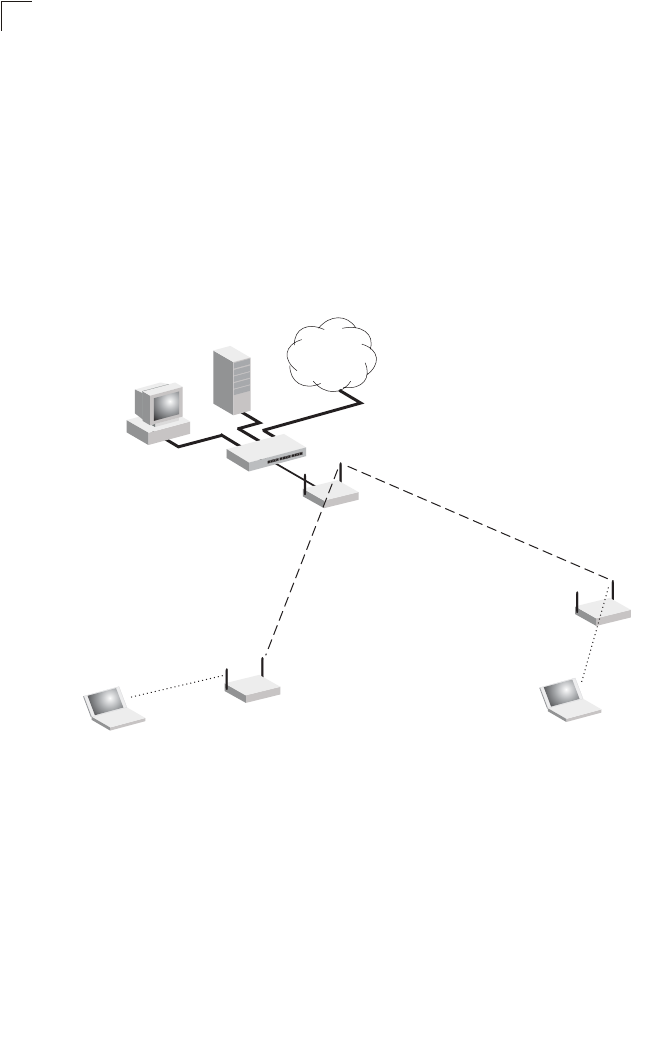
Infrastructure Wireless Bridge
The IEEE 802.11 standard defines a WIreless Distribution System (WDS) for bridge
connections between BSS areas (access points). The access point uses WDS to
forward traffic on links between units.
The access point supports WDS bridge links on either the 5 GHz (802.11a) or
2.4 GHz (802.11b/g) bands and can be used with various external antennas to offer
flexible deployment options.
Up to six WDS bridge links can be specified for each unit in the wireless bridge
network. One unit only must be configured as the “root bridge” in the wireless
network. The root bridge should be the unit connected to the main core of the wired
LAN. Other bridges must configure one “parent” link to the root bridge or to a bridge
connected to the root bridge. The other five available WDS links can be specified as
“child” links to other bridges. This forms a tiered-star topology for the wireless bridge
network.
When using WDS on a radio band, only wireless bridge units can associate to each
other. Wireless clients can only associate with the access point using a radio band
set to access point or repeater mode.
Wireless Bridge Links
Between Access Points
802.11a Radio
Bridge Link
802.11g Radio
AP Link 802.11a Radio
Bridge Link
802.11g Radio
AP Link
802.11g Radio
AP Link
Root Bridge
Bridge
802.11a Radio
Bridge Link
802.11g Radio
AP Link Bridge
Bridge
Network
Core
Network Configuration
4-6
4
Infrastructure Wireless Repeater
The access point can also operate in a bridge “repeater” mode to extend the range
of links to wireless clients. The access point uses WDS to forward traffic between
the repeater bridge and the root bridge. The access point supports up to six WDS
repeater links.
In repeater mode, the access point does not support an Ethernet link to a wired LAN.
Note that when the access point operates in this mode only half the normal
throughput is possible. This is because the access point has to receive and then
re-transmit all data on the same channel.
Wireless Repeater Links
Between Access Points
802.11g Radio
Repeater Link
802.11g Radio
Repeater Link
802.11g Radio
AP Link
802.11g Radio
AP Link
Root Bridge
Repeater
Network
Core
Repeater

5-1
Chapter 5: Initial Configuration
The 2.4 GHz/5 GHz Wireless Access Point offers a variety of management options,
including a web-based interface, a direct connection to the console port, Telnet,
Secure Shell (SSH), or using SNMP software.
The initial configuration steps can be made through the web browser interface or
CLI. The access point requests an IP address via DHCP by default. If no response is
received from the DHCP server, then the access point uses the default address
192.168.1.1. If this address is not compatible with your network, you can first use the
command line interface (CLI) as described below to configure a valid address.
Note: Units sold in countries outside the United States are not configured with a specific
country code. You must use the CLI to set the country code and enable wireless
operation (page 5-3).
Initial Setup through the CLI
Required Connections
The access point provides an RS-232 serial port that enables a connection to a PC
or terminal for monitoring and configuration. Attach a VT100-compatible terminal, or
a PC running a terminal emulation program to the access point. You can use the
console cable provided with this package, or use a cable that complies with the
wiring assignments shown on page B-3.
To connect to the console port, complete the following steps:
1. Connect the console cable to the serial port on a terminal, or a PC running
terminal emulation software, and tighten the captive retaining screws on the
DB-9 connector.
2. Connect the other end of the cable to the RS-232 serial port on the access
point.
3. Make sure the terminal emulation software is set as follows:
• Select the appropriate serial port (COM port 1 or 2).
• Set the data rate to 9600 baud.
• Set the data format to 8 data bits, 1 stop bit, and no parity.
• Set flow control to none.
• Set the emulation mode to VT100.
• When using HyperTerminal, select Terminal keys, not Windows keys.

Initial Configuration
5-2
5
Note: When using HyperTerminal with Microsoft® Windows® 2000, make sure that you
have Windows 2000 Service Pack 2 or later installed. Windows 2000 Service
Pack 2 fixes the problem of arrow keys not functioning in HyperTerminal’s VT100
emulation. See www.microsoft.com for information on Windows 2000 service
packs.
4. Once you have set up the terminal correctly, press the [Enter] key to initiate the
console connection. The console login screen will be displayed.
For a description of how to use the CLI, see “Using the Command Line Interface” on
page 7-1. For a list of all the CLI commands and detailed information on using the
CLI, refer to “Command Groups” on page 7-6.
Initial Configuration Steps
Logging In – Enter “admin” for the user name. The default password is null, so just
press [Enter] at the password prompt. The CLI prompt appears displaying the
access point’s name.
Setting the IP Address – By default, the access point is configured to obtain IP
address settings from a DHCP server. If a DHCP server is not available, the IP
address defaults to 192.168.1.1, which may not be compatible with your network.
You will therefore have to use the command line interface (CLI) to assign an IP
address that is compatible with your network.
Type “configure” to enter configuration mode, then type “interface ethernet” to
access the Ethernet interface-configuration mode.
First type “no ip dhcp” to disable DHCP client mode. Then type “ip address
ip-address netmask gateway,” where “ip-address” is the access point’s IP address,
“netmask” is the network mask for the network, and “gateway” is the default gateway
router. Check with your system administrator to obtain an IP address that is
compatible with your network.
Username: admin
Password:
Enterprise AP#
Enterprise AP#configure
Enterprise AP(config)#interface ethernet
Enterprise AP(config-if)#
Enterprise AP(if-ethernet)#no ip dhcp
Enterprise AP(if-ethernet)#ip address 192.168.2.2
255.255.255.0 192.168.2.254
Enterprise AP(if-ethernet)#
Logging In
5-3
5
After configuring the access point’s IP parameters, you can access the management
interface from anywhere within the attached network. The command line interface
can also be accessed using Telnet from any computer attached to the network.
Setting the Country Code – Units sold in the United States are configured by
default to use only radio channels 1-11 in 802.11b or 802.11g mode as defined by
FCC regulations. Units sold in other countries are configured by default without a
country code (i.e., 99). You must use the CLI to set the country code. Setting the
country code restricts operation of the access point to the radio channels and
transmit power levels permitted for wireless networks in the specified country.
Type “exit” to leave configuration mode. Then type “country ?” to display the list of
countries. Select the code for your country, and enter the country command again,
following by your country code (e.g., tw for Taiwan).
Note: Command examples shown later in this manual abbreviate the console prompt to
“AP” for simplicity.
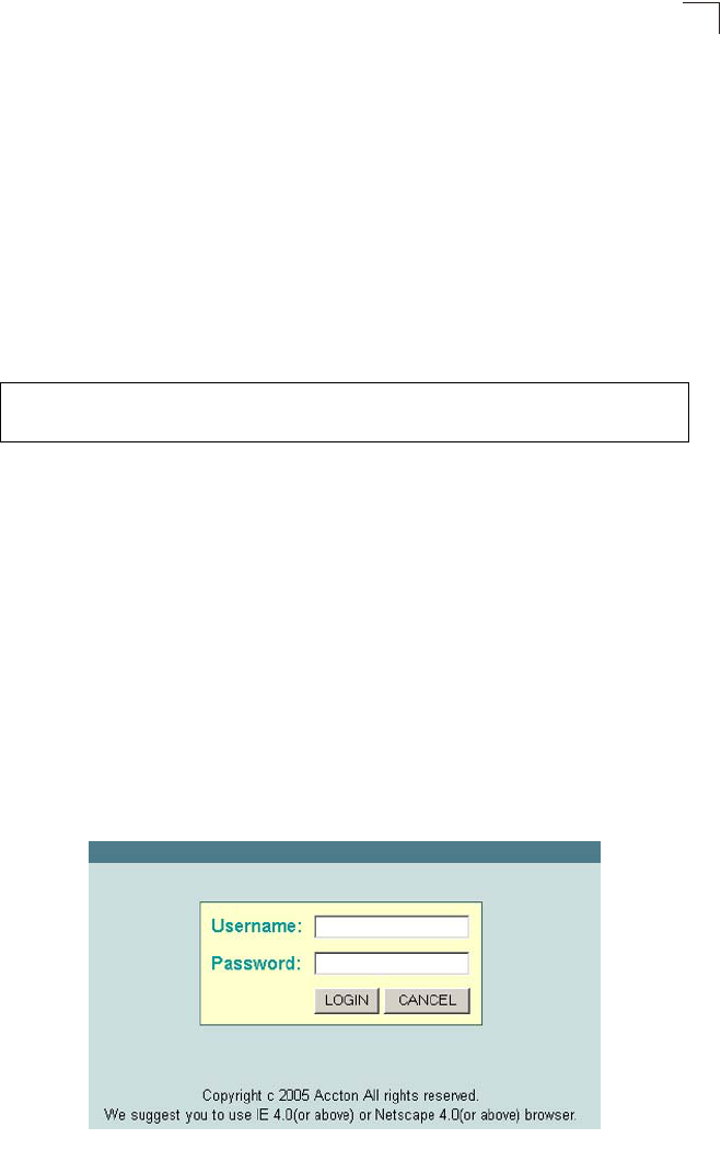
Logging In
There are only a few basic steps you need to complete to connect the access point
to your corporate network, and provide network access to wireless clients.
The access point can be managed by any computer using a web browser (Internet
Explorer 5.0 or above, or Netscape Navigator 6.2 or above). Enter the default IP
address: http://192.168.1.1
Logging In – Enter the username “admin,” the password is null, so just press just
leave it blank and click LOGIN. For information on configuring a user name and
password, see page 6-28.
Enterprise AP#country tw
Enterprise AP#

Initial Configuration
5-4
5
The home page displays the Main Menu.

6-1
Chapter 6: System Configuration
Before continuing with advanced configuration, first complete the initial configuration
steps described in Chapter 4 to set up an IP address for the access point.
The access point can be managed by any computer using a web browser (Internet
Explorer 5.0 or above, or Netscape Navigator 6.2 or above). Enter the configured IP
address of the access point, or use the default address: http://192.168.1.1
To log into the access point, enter the default user name “admin”, leave the
password blank, and press “LOGIN”. When the home page displays, click on
Advanced Setup. The following page will display.
The information in this chapter is organized to reflect the structure of the web
screens for easy reference. However, it is recommended that you configure a user
name and password as the first step under advanced configuration to control
management access to this device (page 6-28).

System Configuration
6-2
6
Advanced Configuration
The Advanced Configuration pages include the following options.
Table 6-2. Menu
Menu Description Page
System Configures basic administrative and client access 6-3
Identification Specifies the host name 6-3
TCP / IP Settings Configures the IP address, subnet mask, gateway, and domain
name servers 6-5
RADIUS Configures the RADIUS server for wireless client authentication
and accounting 6-7
SSH Settings Configures Secure Shell management access 6-11
Authentication Configures 802.1X client authentication, with an option for MAC
address authentication 6-12
Filter Control Filters communications between wireless clients, access to the
management interface from wireless clients, and traffic matching
specific Ethernet protocol types
6-17
VLAN Enables VLAN support and sets the management VLAN ID 6-19
WDS Settings Configures bridge or repeater modes for each radio interface and
sets spanning tree parameters 6-21
AP Management Configures access to management interfaces 6-27
Administration Configures user name and password for management
access;
upgrades software from local file, FTP or TFTP server;
resets
configuration settings to factory defaults; and resets the access
point
6-28
System Log Controls logging of error messages; sets the system clock via
SNTP server or manual configuration 6-33
Mesh Settings Configures meshing functions. 6-37
SNMP Configures SNMP settings 6-37
SNMP Controls access to this access point from management stations
using SNMP, as well as the hosts that will receive trap messages 6-37
SNMP Trap Filters Defines trap filters for SNMPv3 users 6-44
SNMP Targets Specifies SNMPv3 users that will receive trap messages 6-46
Radio Interface A Configures the IEEE 802.11a interface 6-48
Radio Settings Configures common radio signal parameters and other settings for
each VAP interface 6-49
Security Enables each virtual access point (VAP) interface, sets the Service
Set Identifier (SSID), and configures wireless security 6-66
Radio Interface G Configures the IEEE 802.11g interface 6-48
Radio Settings Configures common radio signal parameters and other settings for
each VAP interface 6-63
Advanced Configuration
6-3
6
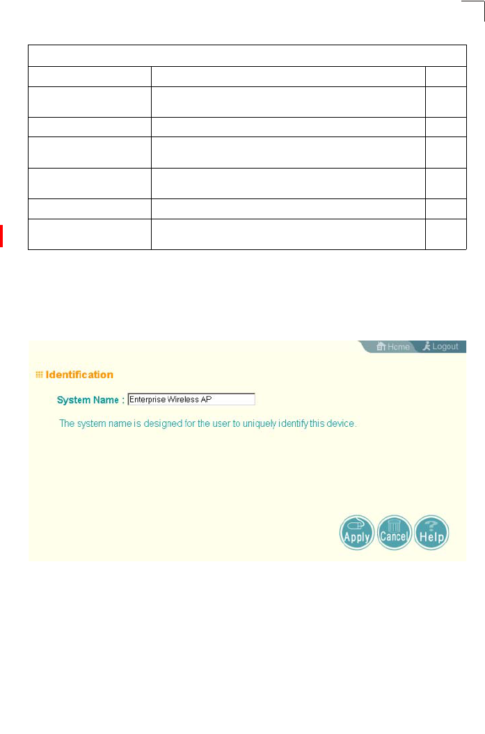
System Identification
The system name for the access point can be left at its default setting. However,
modifying this parameter can help you to more easily distinguish different devices in
your network.
System Name – An alias for the access point, enabling the device to be uniquely
identified on the network. (Default: SMC; Range: 1-32 characters)
Security Enables each VAP interface, sets the SSID, and configures
wireless security 6-66
Status Displays information about the access point and wireless clients 6-84
AP Status Displays configuration settings for the basic system and the
wireless interface 6-84
Station Station Shows the wireless clients currently associated with the access
point 6-87
Event Logs Shows log messages stored in memory 6-90
Mesh Status Displays information on the mesh configuration settings and
current network topology 6-91
Table 6-2. Menu
Menu Description Page

System Configuration
6-4
6
CLI Commands for System Identification – Enter the global configuration mode, and
use the system name command to specify a new system name. Then return to the
Exec mode, and use the show system command to display the changes to the
system identification settings.
Enterprise AP#config
Enterprise AP(config)#system name R&D 7-14
Enterprise AP(config)#end 7-87
Enterprise AP#show system 7-23
Enterprise AP#config 7-8
Enter configuration commands, one per line.
Enterprise AP(config)#system name R&D 7-14
Enterprise AP(config)#end 7-87
Enterprise AP#show system 7-23
System Information
==============================================================
Serial Number :
System Up time : 0 days, 0 hours, 32 minutes, 22 seconds
System Name : R&D
System Location :
System Contact : Contact
System Country Code : US - UNITED STATES
MAC Address : 00-12-CF-12-34-60
Radio A MAC Address : 00-12-CF-12-34-61
Radio G MAC Address : 00-12-CF-12-34-65
IP Address : 192.168.1.1
Subnet Mask : 255.255.255.0
Default Gateway : 0.0.0.0
VLAN State : DISABLED
Management VLAN ID(AP): 1
IAPP State : ENABLED
DHCP Client : ENABLED
HTTP Server : ENABLED
HTTP Server Port : 80
HTTPS Server : ENABLED
HTTPS Server Port : 443
Slot Status : Dual band(a/g)
Boot Rom Version : v1.1.5
Software Version : v4.3.2.0b01
SSH Server : ENABLED
SSH Server Port : 22
Telnet Server : ENABLED
WEB Redirect : DISABLED
DHCP Relay : DISABLED
==============================================================
Enterprise AP#

Advanced Configuration
6-5
6
TCP / IP Settings
Configuring the access point with an IP address expands your ability to manage the
access point. A number of access point features depend on IP addressing to
operate.
Note: You can use the web browser interface to access IP addressing only if the access
point already has an IP address that is reachable through your network.
By default, the access point will be automatically configured with IP settings from a
Dynamic Host Configuration Protocol (DHCP) server. However, if you are not using
a DHCP server to configure IP addressing, use the CLI to manually configure the
initial IP values (see page 5-2). After you have network access to the access point,
you can use the web browser interface to modify the initial IP configuration, if
needed.
Note: If there is no DHCP server on your network, or DHCP fails, the access point will
automatically start up with a default IP address of 192.168.1.1.
DHCP Client (Enable) – Select this option to obtain the IP settings for the access
point from a DHCP (Dynamic Host Configuration Protocol) server. The IP address,
subnet mask, default gateway, and Domain Name Server (DNS) address are
dynamically assigned to the access point by the network DHCP server.
(Default: Enabled)
DHCP Client (Disable) – Select this option to manually configure a static address for
the access point.
• IP Address: The IP address of the access point. Valid IP addresses consist of four
decimal numbers, 0 to 255, separated by periods.

System Configuration
6-6
6
• Subnet Mask: The mask that identifies the host address bits used for routing to
specific subnets.
• Default Gateway: The default gateway is the IP address of the router for the
access point, which is used if the requested destination address is not on the local
subnet.
If you have management stations, DNS, RADIUS, or other network servers
located on another subnet, type the IP address of the default gateway router in the
text field provided. Otherwise, leave the address as all zeros (0.0.0.0).
• Primary and Secondary DNS Address: The IP address of Domain Name Servers
on the network. A DNS maps numerical IP addresses to domain names and can
be used to identify network hosts by familiar names instead of the IP addresses.
If you have one or more DNS servers located on the local network, type the IP
addresses in the text fields provided. Otherwise, leave the addresses as all zeros
(0.0.0.0).
CLI Commands for TCP/IP Settings – From the global configuration mode, enter the
interface configuration mode with the interface ethernet command. Use the ip
dhcp command to enable the DHCP client, or no ip dhcp to disable it. To manually
configure an address, specify the new IP address, subnet mask, and default
gateway using the ip address command. To specify DNS server addresses use the
dns server command. Then use the show interface ethernet command from the
Exec mode to display the current IP settings.
Enterprise AP(config)#interface ethernet 7-87
Enter Ethernet configuration commands, one per line.
Enterprise AP(if-ethernet)#no ip dhcp 7-89
Enterprise AP(if-ethernet)#ip address 192.168.1.2
255.255.255.0 192.168.1.253 7-88
Enterprise AP(if-ethernet)#dns primary-server 192.168.1.55 7-88
Enterprise AP(if-ethernet)#dns secondary-server 10.1.0.55 7-88
Enterprise AP(config)#end 7-8
Enterprise AP#show interface ethernet 7-91
Ethernet Interface Information
========================================
IP Address : 192.168.1.2
Subnet Mask : 255.255.255.0
Default Gateway : 192.168.1.253
Primary DNS : 192.168.1.55
Secondary DNS : 10.1.0.55
Speed-duplex : 100Base-TX Full Duplex
Admin status : Up
Operational status : Up
========================================
Enterprise AP#

Advanced Configuration
6-7
6
RADIUS
Remote Authentication Dial-in User Service (RADIUS) is an authentication protocol
that uses software running on a central server to control access to RADIUS-aware
devices on the network. An authentication server contains a database of user
credentials for each user that requires access to the network.
A primary RADIUS server must be specified for the access point to implement IEEE
802.1X network access control and Wi-Fi Protected Access (WPA) wireless security.
A secondary RADIUS server may also be specified as a backup should the primary
server fail or become inaccessible.
In addition, the configured RADIUS server can also act as a RADIUS Accounting
server and receive user-session accounting information from the access point.
RADIUS Accounting can be used to provide valuable information on user activity in
the network.
Note: This guide assumes that you have already configured RADIUS server(s) to
support the access point. Configuration of RADIUS server software is beyond the
scope of this guide, refer to the documentation provided with the RADIUS server
software.
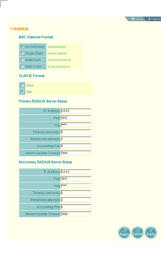
System Configuration
6-8
6

Advanced Configuration
6-9
6
Primary Radius Server Setup – Configure the following settings to use RADIUS
authentication on the access point.
• IP Address: Specifies the IP address or host name of the RADIUS server.
• Port: The UDP port number used by the RADIUS server for authentication
messages. (Range: 1024-65535; Default: 1812)
• Key: A shared text string used to encrypt messages between the access point and
the RADIUS server. Be sure that the same text string is specified on the RADIUS
server. Do not use blank spaces in the string. (Maximum length: 255 characters)
• Timeout: Number of seconds the access point waits for a reply from the RADIUS
server before resending a request. (Range: 1-60 seconds; Default: 5)
• Retransmit attempts: The number of times the access point tries to resend a
request to the RADIUS server before authentication fails. (Range: 1-30; Default: 3)
• Interim Update Timeout: The interval between transmitting accounting updates to
the RADIUS server. (Range: 60-86400; Default: 3600 seconds)
Note: For the Timeout and Retransmit attempts fields, accept the default values unless
you experience problems connecting to the RADIUS server over the network.
Secondary Radius Server Setup – Configure a secondary RADIUS server to provide
a backup in case the primary server fails. The access point uses the secondary
server if the primary server fails or becomes inaccessible. Once the access point
switches over to the secondary server, it periodically attempts to establish
communication again with primary server. If communication with the primary server
is re-established, the secondary server reverts to a backup role.

System Configuration
6-10
6
CLI Commands for RADIUS – From the global configuration mode, use the
radius-server address command to specify the address of the primary or
secondary RADIUS servers. (The following example configures the settings for the
primary RADIUS server.) Configure the other parameters for the RADIUS server.
Then use the show show radius command from the Exec mode to display the
current settings for the primary and secondary RADIUS servers.
Enterprise AP(config)#radius-server address 192.168.1.25 7-59
Enterprise AP(config)#radius-server port 181 7-60
Enterprise AP(config)#radius-server key green 7-60
Enterprise AP(config)#radius-server timeout 10 7-61
Enterprise AP(config)#radius-server retransmit 5 7-61
Enterprise AP(config)#radius-server port-accounting 1813 7-62
Enterprise AP(config)#radius-server timeout-interim 500 7-62
Enterprise AP(config)#exit
Enterprise AP#show radius 7-64
Radius Server Information
========================================
IP : 192.168.1.25
Port : 181
Key : *****
Retransmit : 5
Timeout : 10
Radius MAC format : no-delimiter
Radius VLAN format : HEX
========================================
Radius Secondary Server Information
========================================
IP : 0.0.0.0
Port : 1812
Key : *****
Retransmit : 3
Timeout : 5
Radius MAC format : no-delimiter
Radius VLAN format : HEX
========================================
Enterprise AP#
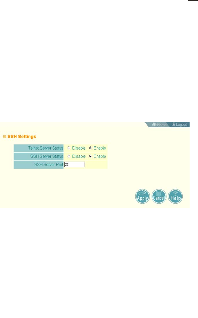
Advanced Configuration
6-11
6
SSH Settings
Telnet is a remote management tool that can be used to configure the access point
from anywhere in the network. However, Telnet is not secure from hostile attacks.
The Secure Shell (SSH) can act as a secure replacement for Telnet. The SSH
protocol uses generated public keys to encrypt all data transfers passing between
the access point and SSH-enabled management station clients and ensures that
data traveling over the network arrives unaltered. Clients can then securely use the
local user name and password for access authentication.
Note that SSH client software needs to be installed on the management station to
access the access point for management via the SSH protocol.
Notes: 1. The access point supports only SSH version 2.0.
2. After boot up, the SSH server needs about two minutes to generate host
encryption keys. The SSH server is disabled while the keys are being
generated.
SSH Settings
• SSH Server Status: Enables or disables the SSH server. (Default: Enabled)
• SSH Server Port: Sets the UDP port for the SSH server. (Range: 1-65535;
Default: 22)
CLI Commands for SSH – To enable the SSH server, use the ip ssh-server enable
command from the CLI Ethernet interface configuration mode. To set the SSH
server UDP port, use the ip ssh-server port command. To view the current settings,
use the show system command from the CLI Exec mode (not shown in the
following example).
Enterprise AP(if-ethernet)#ip ssh-server enable 7-16
Enterprise AP(if-ethernet)#ip ssh-server port 1124 7-16
Enterprise AP(if-ethernet)#exit
Enterprise AP(if-ethernet)#configure

System Configuration
6-12
6
Authentication
Wireless clients can be authenticated for network access by checking their MAC
address against the local database configured on the access point, or by using a
database configured on a central RADIUS server. Alternatively, authentication can
be implemented using the IEEE 802.1X network access control protocol.
A client’s MAC address provides relatively weak user authentication, since MAC
addresses can be easily captured and used by another station to break into the
network. Using 802.1X provides more robust user authentication using user names
and passwords or digital certificates. You can configure the access point to use both
MAC address and 802.1X authentication, with client station MAC authentication
occurring prior to IEEE 802.1X authentication. However, it is better to choose one or
the other, as appropriate.
Take note of the following points before configuring MAC address or 802.1X
authentication:
• Use MAC address authentication for a small network with a limited number of
users. MAC addresses can be manually configured on the access point itself
without the need to set up a RADIUS server, but managing a large number of MAC
addresses across many access points is very cumbersome. A RADIUS server can
be used to centrally manage a larger database of user MAC addresses.
• Use IEEE 802.1X authentication for networks with a larger number of users and
where security is the most important issue. When using 802.1X authentication, a
RADIUS server is required in the wired network to centrally manage the
credentials of the wireless clients. It also provides a mechanism for enhanced
network security using dynamic encryption key rotation or W-Fi Protected Access
(WPA).
Note: If you configure RADIUS MAC authentication together with 802.1X, RADIUS MAC
address authentication is performed prior to 802.1X authentication. If RADIUS
MAC authentication succeeds, then 802.1X authentication is performed. If
RADIUS MAC authentication fails, 802.1X authentication is not performed.
• The access point can also operate in a 802.1X supplicant mode. This enables the
access point itself to be authenticated with a RADIUS server using a configured
MD5 user name and password. This prevents rogue access points from gaining
access to the network.
Note: The 802.1X supplicant mode is only configurable using the CLI.
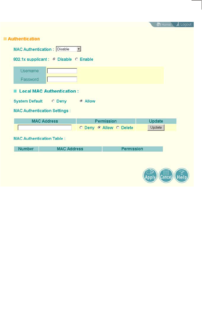
Advanced Configuration
6-13
6
MAC Authentication – You can configure a list of the MAC addresses for wireless
clients that are authorized to access the network. This provides a basic level of
authentication for wireless clients attempting to gain access to the network. A
database of authorized MAC addresses can be stored locally on the access point or
remotely on a central RADIUS server.
(Default: Disabled)
• Disabled: No checks are performed on an associating station’s MAC address.
• Local MAC: The MAC address of the associating station is compared against the
local database stored on the access point. Use the Local MAC Authentication
section of this web page to set up the local database, and configure all access
points in the wireless network service area with the same MAC address database.
• Radius MAC: The MAC address of the associating station is sent to a configured
RADIUS server for authentication. When using a RADIUS authentication server
for MAC address authentication, the server must first be configured in the Radius
window (see “RADIUS” on page 6-7). The database of MAC addresses and
filtering policy must be defined in the RADIUS server.
Note: MAC addresses on the RADIUS server can be entered in four different formats
(see “radius-server radius-mac-format” on page 7-63).

System Configuration
6-14
6
MAC Authentication Session Timeout – Sets the interval at which associated clients
will be re-authenticated with the RADIUS server. (Range: 0-1440 minutes; Default:
0, that is, disabled)
WEB Redirect – Enables web-based authentication of wireless clients. This feature
supports billing for a public access wireless network without requiring 802.1X or
MAC authentication. After successful association to an access point, a client is
“redirected” to an access point login web page as soon as Internet access is
attempted. The client is then authenticated by entering a user name and password
on the web page. Authentication is determined by checking these credentials
against a database of user names and passwords stored n a RADIUS server that is
attached to the wired network. For information on configuring the RADIUS server’s
details on the access point, see “RADIUS Client” on page 6-54. (Default: Disabled)
Note: Enabling Web Redirect will cause the system to reboot after 5 seconds.
Local MAC Authentication – Configures the local MAC authentication database. The
MAC database provides a mechanism to take certain actions based on a wireless
client’s MAC address. The MAC list can be configured to allow or deny network
access to specific clients.
• System Default: Specifies a default action for all unknown MAC addresses (that
is, those not listed in the local MAC database).
• Deny: Blocks access for all MAC addresses except those listed in the local
database as “Allow.”
• Allow: Permits access for all MAC addresses except those listed in the local
database as “Deny.”
• MAC Authentication Settings: Enters specified MAC addresses and permissions
into the local MAC database.
• MAC Address: Physical address of a client. Enter six pairs of hexadecimal digits
separated by hyphens; for example, 00-90-D1-12-AB-89.
• Permission: Select Allow to permit access or Deny to block access. If Delete is
selected, the specified MAC address entry is removed from the database.
• Update: Enters the specified MAC address and permission setting into the local
database.
• MAC Authentication Table: Displays current entries in the local MAC database.

Advanced Configuration
6-15
6
CLI Commands for Local MAC Authentication – Use the mac-authentication
server command from the global configuration mode to enable local MAC
authentication. Use the mac-authentication session-timeout command to set the
authentication interval, and web-redirect command to enable web-based
authentication for service billing. Set the default action for MAC addresses not in the
local table using the address filter default command, then enter MAC addresses in
the local table using the address filter entry command. To remove an entry from
the table, use the address filter delete command. To display the current settings,
use the show authentication command from the Exec mode.
Enterprise AP(config)#mac-authentication server local 7-72
Enterprise AP(config)#mac-authentication session-timeout 5 7-72
Enterprise AP(config)#web-redirect 7-20
Enterprise AP(config)#address filter default denied 7-70
Enterprise AP(config)#address filter entry
00-70-50-cc-99-1a denied 7-71
Enterprise AP(config)#address filter entry
00-70-50-cc-99-1b allowed
Enterprise AP(config)#address filter entry
00-70-50-cc-99-1c allowed
Enterprise AP(config)#address filter delete
00-70-50-cc-99-1c 7-71
Enterprise AP(config)#exit
Enterprise AP#show authentication 7-68
Authentication Information
===========================================================
MAC Authentication Server : LOCAL
MAC Auth Session Timeout Value : 0 min
802.1x supplicant : DISABLED
802.1x supplicant user : EMPTY
802.1x supplicant password : EMPTY
Address Filtering : DENIED
System Default : ALLOW addresses not found in filter table.
Filter Table
MAC Address Status
----------------- ----------
00-70-50-cc-99-1a DENIED
00-70-50-cc-99-1b ALLOWED
=========================================================
Enterprise AP#

System Configuration
6-16
6
CLI Commands for RADIUS MAC Authentication – Use the mac-authentication
server command from the global configuration mode to enable remote MAC
authentication. Set the timeout value for re-authentication using the mac-
authentication session-timeout command. Be sure to also configure connection
settings for the RADIUS server (not shown in the following example). To display the
current settings, use the show authentication command from the Exec mode.
CLI Command for Web Redirect – To configure the access point to use web redirect,
first use the web-redirect command under global configuration mode. To display the
current settings, use the show system command from the Exec mode (not shown in
the following example).
CLI Command for 802.1x Supplicant – To configure the access point to operate as a
802.1X supplicant, first use the 802.1X supplicant user command to set a user
name and password for the access point, then use the 802.1X supplicant command
to enable the feature. To display the current settings, use the show authentication
command from the Exec mode (not shown in the following example)
Enterprise AP(config)#mac-authentication server remote 7-72
Enterprise AP(config)#mac-authentication
session-timeout 300 7-72
Enterprise AP(config)#exit
Enterprise AP#show authentication 7-68
Authentication Information
===========================================================
MAC Authentication Server : REMOTE
MAC Auth Session Timeout Value : 300 min
802.1x supplicant : DISABLED
802.1x supplicant user : EMPTY
802.1x supplicant password : EMPTY
Address Filtering : DENIED
System Default : DENY addresses not found in filter table.
Filter Table
MAC Address Status
----------------- ----------
00-70-50-cc-99-1a DENIED
00-70-50-cc-99-1b ALLOWED
=========================================================
Enterprise AP#
Enterprise AP(config)#web-redirect 7-68
Enterprise AP(config)#
Enterprise AP(config)#802.1X supplicant user WA6102 dot1xpass 7-68
Enterprise AP(config)#802.1X supplicant 7-68
Enterprise AP(config)#
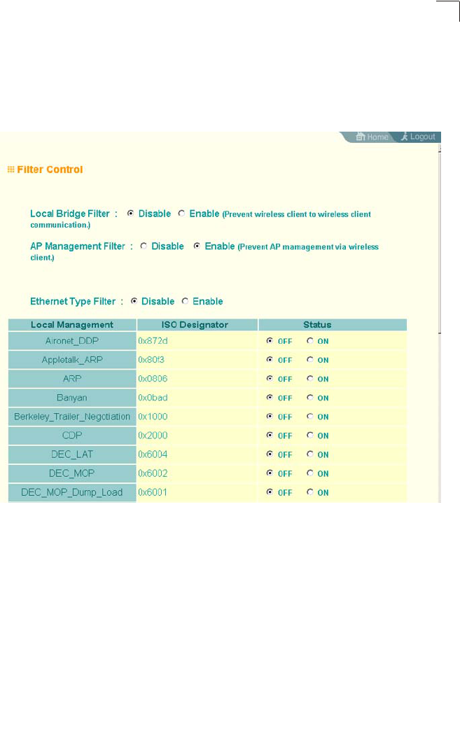
Advanced Configuration
6-17
6
Filter Control
The access point can employ network traffic frame filtering to control access to
network resources and increase security. You can prevent communications between
wireless clients and prevent access point management from wireless clients. Also,
you can block specific Ethernet traffic from being forwarded by the access point.
IAPP – Enables roaming between multi-vendor access points.
Local Bridge Filter – Controls wireless-to-wireless communications between clients
through the access point. However, it does not affect communications between
wireless clients and the wired network. (Default: Enabled)
• Disabled: Allows wireless-to-wireless communications between clients through
the access point.
• Enabled: Blocks wireless-to-wireless communications between clients through the
access point.
AP Management Filter – Controls management access to the access point from
wireless clients. Management interfaces include the web, Telnet, or SNMP.
(Default: Disabled)
• Disabled: Allows management access from wireless clients.
• Enabled: Blocks management access from wireless clients.

System Configuration
6-18
6
Ethernet Type Filter – Controls checks on the Ethernet type of all incoming and
outgoing Ethernet packets against the protocol filtering table. (Default: Disabled)
• Disabled: Access point does not filter Ethernet protocol types.
• Enabled: Access point filters Ethernet protocol types based on the configuration
of protocol types in the filter table. If the status of a protocol is set to “ON,” the
protocol is filtered from the access point.
Note: Ethernet protocol types not listed in the filtering table are always forwarded by the
access point.
CLI Commands for Bridge Filtering – Use the filter local-bridge command from the
global configuration mode to prevent wireless-to-wireless communications through
the access point. Use the filter ap-manage command to restrict management
access from wireless clients. To configure Ethernet protocol filtering, use the filter
ethernet-type enable command to enable filtering and the filter ethernet-type
protocol command to define the protocols that you want to filter. To remove an entry
from the table, use the address filter delete command. To display the current
settings, use the show filters command from the Exec mode.
Enterprise AP(config)#filter local-bridge 7-73
Enterprise AP(config)#filter ap-manage 7-74
Enterprise AP(config)#filter ethernet-type enable 7-74
Enterprise AP(config)#filter ethernet-type protocol ARP 7-75
Enterprise AP(config)#exit
Enterprise AP#show filters 7-76
Protocol Filter Information
=========================================================
Local Bridge :ENABLED
AP Management :ENABLED
Ethernet Type Filter :ENABLED
Enabled Protocol Filters
---------------------------------------------------------
Protocol: ARP ISO: 0x0806
=========================================================
Enterprise AP#

Advanced Configuration
6-19
6
VLAN
The access point can employ VLAN tagging support to control access to network
resources and increase security. VLANs separate traffic passing between the
access point, associated clients, and the wired network. There can be a VLAN
assigned to each associated client, a default VLAN for each VAP (Virtual Access
Point) interface, and a management VLAN for the access point.
Note the following points about the access point’s VLAN support:
• The management VLAN is for managing the access point through remote
management tools, such as the web interface, SSH, SNMP, or Telnet. The access
point only accepts management traffic that is tagged with the specified
management VLAN ID.
• All wireless clients associated to the access point are assigned to a VLAN. If IEEE
802.1X is being used to authenticate wireless clients, specific VLAN IDs can be
configured on the RADIUS server to be assigned to each client. If a client is not
assigned to a specific VLAN or if 802.1X is not used, the client is assigned to the
default VLAN for the VAP interface with which it is associated. The access point
only allows traffic tagged with assigned VLAN IDs or default VLAN IDs to access
clients associated on each VAP interface.
• When VLAN support is enabled on the access point, traffic passed to the wired
network is tagged with the appropriate VLAN ID, either an assigned client VLAN
ID, default VLAN ID, or the management VLAN ID. Traffic received from the wired
network must also be tagged with one of these known VLAN IDs. Received traffic
that has an unknown VLAN ID or no VLAN tag is dropped.
• When VLAN support is disabled, the access point does not tag traffic passed to
the wired network and ignores the VLAN tags on any received frames.
Note: Before enabling VLAN tagging on the access point, be sure to configure the
attached network switch port to support tagged VLAN frames from the access
point’s management VLAN ID, default VLAN IDs, and other client VLAN IDs.
Otherwise, connectivity to the access point will be lost when you enable the VLAN
feature.
Using IEEE 802.1X and a central RADIUS server, up to 64 VLAN IDs can be
mapped to specific wireless clients, allowing users to remain within the same VLAN
as they move around a campus site. This feature can also be used to control access
to network resources from clients, thereby improving security.
A VLAN ID (1-4094) can be assigned to a client after successful IEEE 802.1X
authentication. The client VLAN IDs must be configured on the RADIUS server for
each user authorized to access the network. If a client does not have a configured
VLAN ID on the RADIUS server, the access point assigns the client to the
configured default VLAN ID for the VAP interface.
Note: When using IEEE 802.1X to dynamically assign VLAN IDs, the access point must
have 802.1X authentication enabled and a RADIUS server configured. Wireless
clients must also support 802.1X client software.
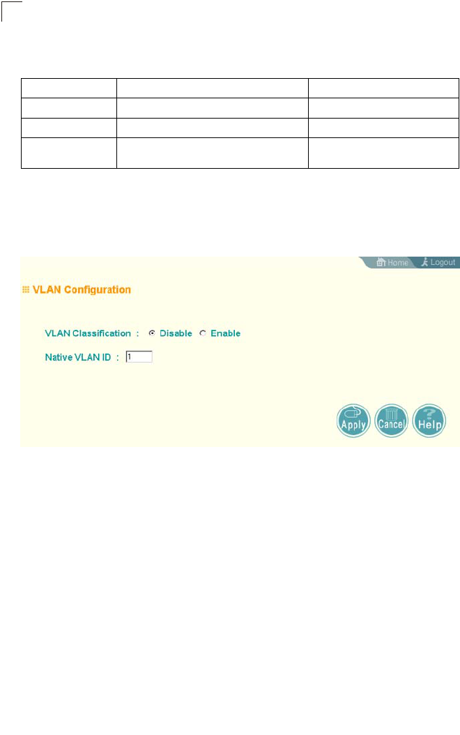
System Configuration
6-20
6
When setting up VLAN IDs for each user on the RADIUS server, be sure to use the
RADIUS attributes and values as indicated in the following table.
VLAN IDs on the RADIUS server can be entered as hexadecimal digits or a string
(see “radius-server vlan-format” on page 7-63).
Note: The specific configuration of RADIUS server software is beyond the scope of this
guide. Refer to the documentation provided with the RADIUS server software.
Management Native VLAN ID – The VLAN ID that traffic must have to be able to
manage the access point. (Range 1-4094; Default: 1)
System VLAN status (forces AP reboot) – Enables or disables VLAN tagging
support on the access point. Changing this parameter automatically reboots the
access point. (Default: Disable)
Number RADIUS Attribute Value
64 Tunnel-Type VLAN (13)
65 Tunnel-Medium-Type 802
81 Tunnel-Private-Group-ID VLANID
(1 to 4094 as hexadecimal or string)
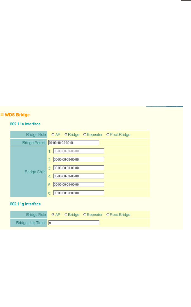
Advanced Configuration
6-21
6
WDS Settings
Each access point radio interface can be configured to operate in a bridge or
repeater mode, which allows it to forward traffic directly to other access point units.
To set up bridge links between access point units, you must configure the WIreless
Distribution System (WDS) forwarding table by specifying the wireless MAC address
of all units to which you want to forward traffic. Up to six WDS bridge or repeater
links can be specified for each unit in the wireless bridge network.
The Spanning Tree Protocol (STP) can be used to detect and disable network loops,
and to provide backup links between bridges. This allows a wireless bridge to
interact with other bridging devices (that is, an STP-compliant switch, bridge or
router) in your network to ensure that only one route exists between any two stations
on the network, and provide backup links which automatically take over when a
primary link goes down.
WDS Bridge – Up to six WDS bridge or repeater links (MAC addresses) per radio
interface can be specified for each unit in the wireless bridge network. One unit only
must be configured as the “root bridge” in the wireless network. The root bridge is
the unit connected to the main core of the wired LAN. Other bridges need to specify
one “Parent” link to the root bridge or to a bridge connected to the root bridge. The
other five WDS links are available as “Child” links to other bridges.
• Bridge Role – Each radio interface can be set to operate in one of the following
four modes: (Default: AP)
• AP (Access Point): Operates as an access point for wireless clients, providing
connectivity to a wired LAN.

System Configuration
6-22
6
• Bridge: Operates as a bridge to other access points. The “Parent” link to the root
bridge must be configured. Up to five other ”Child” links are available to other
bridges.
• Repeater: Operates as a wireless repeater, extending the range for remote
wireless clients and connecting them to the root bridge. The “Parent” link to the
root bridge must be configured. In this mode, traffic is not forwarded to the
Ethernet port from the radio interface.
• Root Bridge: Operates as the root bridge in the wireless bridge network. Up to
six ”Child” links are available to other bridges in the network.
• Bridge Parent – The physical layer address of the root bridge unit or the bridge unit
connected to the root bridge. (12 hexadecimal digits in the form
“xx-xx-xx-xx-xx-xx”)
• Bridge Child – The physical layer address of other bridge units for which this unit
serves as the bridge parent or the root bridge. Note that the first entry under the
list of child nodes is reserved for the root bridge, and can only be configured if the
role is set to “Root Bridge.” (12 hexadecimal digits in the form “xx-xx-xx-xx-xx-xx”)
• Bridge Link Timer – Sets the maximum time the bridge waits to receive a link
message from the parent bridge. (Range: 0 -100; Default: 0, that is disabled)
Child bridges periodically send requests for link information from the parent bridge.
The Parent bridge responds with the information and checks that it was received
by the child bridge. The message includes link information on the connection path
to the root bridge and confirms that the link is valid. If a link is detected as down,
the bridge restarts the association process to try and recover the link.
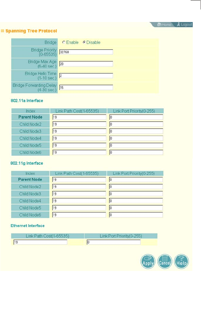
Advanced Configuration
6-23
6
Spanning Tree Protocol – STP uses a distributed algorithm to select a bridging
device (STP-compliant switch, bridge or router) that serves as the root of the
spanning tree network. It selects a root port on each bridging device (except for the
root device) which incurs the lowest path cost when forwarding a packet from that
device to the root device. Then it selects a designated bridging device from each
LAN which incurs the lowest path cost when forwarding a packet from that LAN to
the root device. All ports connected to designated bridging devices are assigned as

System Configuration
6-24
6
designated ports. After determining the lowest cost spanning tree, it enables all root
ports and designated ports, and disables all other ports. Network packets are
therefore only forwarded between root ports and designated ports, eliminating any
possible network loops.
Once a stable network topology has been established, all bridges listen for Hello
BPDUs (Bridge Protocol Data Units) transmitted from the root bridge. If a bridge
does not get a Hello BPDU after a predefined interval (Maximum Age), the bridge
assumes that the link to the root bridge is down. This bridge will then initiate
negotiations with other bridges to reconfigure the network to reestablish a valid
network topology.
• Bridge – Enables/disables STP on the wireless bridge or repeater.
(Default: Disabled)
• Bridge Priority – Used in selecting the root device, root port, and designated port.
The device with the highest priority becomes the STP root device. However, if all
devices have the same priority, the device with the lowest MAC address will then
become the root device. (Note that lower numeric values indicate higher priority.)
• Range: 0-65535
• Default: 32768
• Bridge Max Age – The maximum time (in seconds) a device can wait without
receiving a configuration message before attempting to reconfigure. All device
ports (except for designated ports) should receive configuration messages at
regular intervals. Any port that ages out STP information (provided in the last
configuration message) becomes the designated port for the attached LAN. If it is
a root port, a new root port is selected from among the device ports attached to
the network. (Range: 6-40 seconds)
• Default: 20
• Minimum: The higher of 6 or [2 x (Hello Time + 1)].
• Maximum: The lower of 40 or [2 x (Forward Delay - 1)]
• Bridge Hello Time – Interval (in seconds) at which the root device transmits a
configuration message. (Range: 1-10 seconds)
• Default: 2
• Minimum: 1
• Maximum: The lower of 10 or [(Max. Message Age / 2) -1]
• Bridge Forwarding Delay – The maximum time (in seconds) this device waits
before changing states (i.e., discarding to learning to forwarding). This delay is
required because every device must receive information about topology changes
before it starts to forward frames. In addition, each port needs time to listen for
conflicting information that would make it return to a discarding state; otherwise,
temporary data loops might result. (Range: 4-30 seconds)
• Default: 15
• Minimum: The higher of 4 or [(Max. Message Age / 2) + 1]
• Maximum: 30
• Link Path Cost – This parameter is used by the STP to determine the best path

Advanced Configuration
6-25
6
between devices. Therefore, lower values should be assigned to ports attached to
faster media, and higher values assigned to ports with slower media. (Path cost
takes precedence over port priority.)
• Range: 1-65535
• Default: Ethernet interface: 19; Wireless interface: 40
• Link Port Priority – Defines the priority used for this port in the Spanning Tree
Protocol. If the path cost for all ports on a switch are the same, the port with the
highest priority (i.e., lowest value) will be configured as an active link in the
spanning tree. This makes a port with higher priority less likely to be blocked if the
Spanning Tree Protocol is detecting network loops. Where more than one port is
assigned the highest priority, the port with lowest numeric identifier will be
enabled.
• Default: 128
• Range: 0-240, in steps of 16
CLI Commands for WDS Settings – To set the role of the access point radio
interface, use the bridge role command from the CLI wireless interface
configuration mode. If the role of the radio interface is set to “Bridge” or “Repeater,”
the MAC address of the parent node must also be configured using the bridge-link
parent command. If the role is set to anything other than “Access Point,” then you
should also configure the MAC addresses of the child nodes using the bridge-link
child command. You can also use the bridge-link link-timer command to adjust the
interval at which a node will wait for a spanning-tree message from it’s parent before
trying to recover. To view the current bridge link settings, use the show bridge link
command.
Enterprise AP(if-wireless a)#bridge role bridge 6-96
Enterprise AP(if-wireless a)#bridge-link child 2
00-08-3e-84-bc-6d 6-98
Enterprise AP(if-wireless a)#bridge-link child 3
00-08-3e-85-13-f2
Enterprise AP(if-wireless a)#bridge-link child 4
00-08-3e-84-79-31
Enterprise AP(if-wireless a)#bridge-link parent
00-08-2d-69-3a-51 6-97
Enterprise AP(if-wireless a)#exit
Enterprise AP#show bridge link wireless a 6-101
Interface Wireless A WDS Information
====================================
AP Role: Bridge
Parent: 00-08-2d-69-3a-51
Child:
Child 2: 00-08-3e-84-bc-6d
Child 3: 00-08-3e-85-13-f2
Child 4: 00-08-3e-84-79-31
Child 5: 00-00-00-00-00-00
Child 6: 00-00-00-00-00-00
STAs:
No WDS Stations.
Enterprise AP#

System Configuration
6-26
6
CLI Commands for STP Settings – If the role of a radio interface is set to Repeater,
Bridge or Root Bridge, STP can be enabled on the access point to maintain a valid
network topology. To globally enable STP, use the bridge stp enable command
from the CLI configuration mode. Then configure the other global STP parameters
for the bridge. The path cost and priority for each bridge link can be set using the
bridge-link path-cost and bridge-link port-priority command from the Wireless
Interface configuration mode. The path cost and priority can also be set for the
Ethernet port from the Ethernet Interface configuration mode. To view the current
STP settings, use the show bridge stp command.
Enterprise AP(config)#bridge stp enable 6-104
Enterprise AP(config)#bridge stp forwarding-delay 2500 6-105
Enterprise AP(config)#bridge stp hello-time 500 6-106
Enterprise AP(config)#bridge stp max-age 4000 6-107
Enterprise AP(config)#bridge stp priority 40000 6-108
Enterprise AP(config)#interface wireless a
Enterprise AP(if-wireless a)#bridge-link path-cost 2 40 6-109
Enterprise AP(if-wireless a)#bridge-link port-priority 2 64 6-110
Enterprise AP(if-wireless a)#exit
Enterprise AP#show bridge stp 6-111
Bridge MAC : 00:30:F1:F0:9A:9C
Status : Disabled
priority : 32768
desiginated-root : priority = 0, MAC = 00:00:00:00:00:00
root-path-cost : 0
root-Port-no : 0
Hold Time : 0 Seconds
Hello Time : 0 Seconds
Maximum Age : 0 Seconds
Forward Delay : 0 Seconds
bridge Hello Time : 2 Seconds
bridge Maximum Age : 20 Seconds
bridge Forward Delay : 5 Seconds
time-since-top-change: 3168 Seconds
topology-change-count: 0
Enterprise AP#
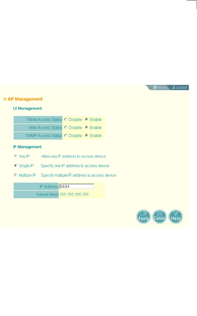
Advanced Configuration
6-27
6
AP Management
The Web, Telnet, and SNMP management interfaces are enabled and open to all IP
addresses by default. To provide more security for management access to the
access point, specific interfaces can be disabled and management restricted to a
single IP address or a limited range of IP addresses.
Once you specify an IP address or range of addresses, access to management
interfaces is restricted to the specified addresses. If anyone tries to access a
management interface from an unauthorized address, the access point will reject the
connection.
UI Management – Enables or disables management access through Telnet, the Web
(HTTP), or SNMP interfaces. (Default: Enabled)
Note: Secure Web (HTTPS) connections are not affected by the UI Management or IP
Management settings.
IP Management – Restricts management access to Telnet, Web, and SNMP
interfaces to specified IP addresses. (Default: Any IP)
• Any IP: Indicates that any IP address is allowed management access.
• Single IP: Specifies a single IP address that is allowed management access.
• Multiple IP: Specifies an address range as defined by the entered IP address and
subnet mask. For example, IP address 192.168.1.6 and subnet mask
255.255.255.0, defines all IP addresses from 192.168.1.1 to 192.168.1.254.

System Configuration
6-28
6
CLI Commands for AP Management features.
Administration
Changing the Password
Management access to the web and CLI interface on the access point is controlled
through a single user name and password. You can also gain additional access
security by using control filters (see “Filter Control” on page 6-17).
To protect access to the management interface, you need to configure an
Administrator’s user name and password as soon as possible. If the user name and
password are not configured, then anyone having access to the access point may
be able to compromise access point and network security. Once a new Administrator
has been configured, you can delete the default “admin” user name from the system.
Note: Pressing the Reset button on the back of the access point for more than five
seconds resets the user name and password to the factory defaults. For this
reason, we recommend that you protect the access point from physical access by
unauthorized persons.
Username – The name of the user. The default name is “admin.” (Length: 3-16
characters, case sensitive)
New Password – The password for management access. (Length: 3-16 characters,
case sensitive)
Confirm New Password – Enter the password again for verification.
Enterprise AP(config)#apmgmtip multiple 192.168.1.50 255.255.255.0 7-21
Enterprise AP(config)#apmgmtui SNMP enable 7-22
Enterprise AP(config)#ip http server 7-18
Enterprise AP(config)#ip http port 769 7-17
Enterprise AP(config)#ip https server 7-18
Enterprise AP(config)#ip https port 1234 7-18

Advanced Configuration
6-29
6
CLI Commands for the Administrator’s User Name and Password – Use the
username and password commands from the CLI configuration mode.
Upgrading Firmware
You can upgrade new access point software from a local file on the management
workstation, or from an FTP or TFTP server. New software may be provided
periodically from your distributor.
After upgrading new software, you must reboot the access point to implement the
new code. Until a reboot occurs, the access point will continue to run the software it
was using before the upgrade started. Also note that new software that is
incompatible with the current configuration automatically restores the access point to
the factory default settings when first activated after a reboot.
Enterprise AP(config)#username bob 7-15
Enterprise AP(config)#password admin 7-15
Enterprise AP#
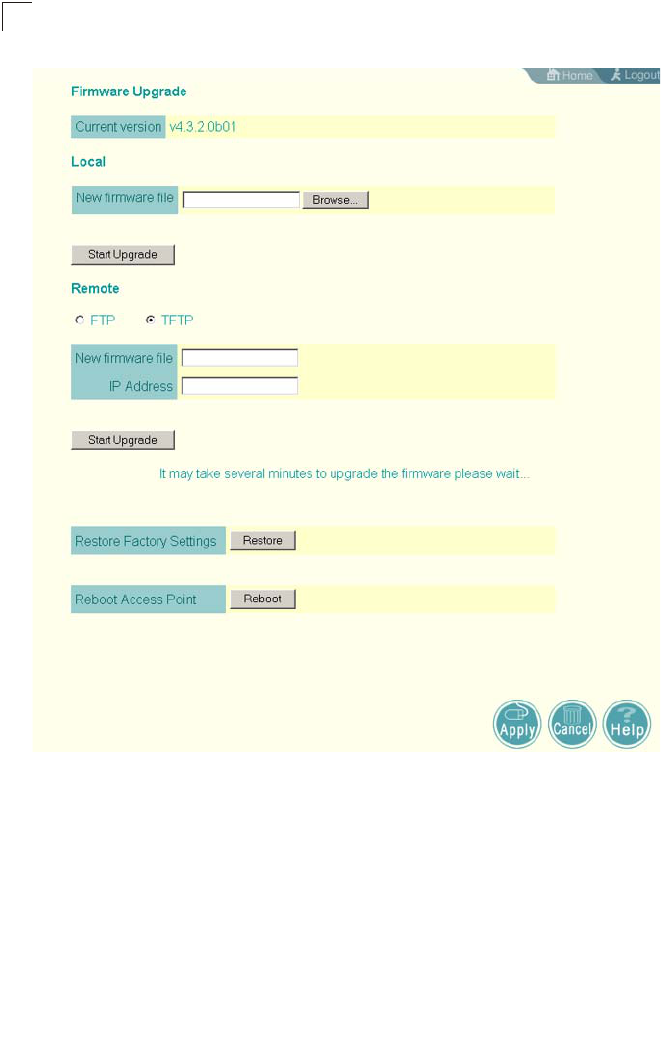
System Configuration
6-30
6
Before upgrading new software, verify that the access point is connected to the
network and has been configured with a compatible IP address and subnet mask.
If you need to download from an FTP or TFTP server, take the following additional
steps:
• Obtain the IP address of the FTP or TFTP server where the access point software
is stored.
• If upgrading from an FTP server, be sure that you have an account configured on
the server with a user name and password.

Advanced Configuration
6-31
6
• If VLANs are configured on the access point, determine the VLAN ID with which
the FTP or TFTP server is associated, and then configure the management
station, or the network port to which it is attached, with the same VLAN ID. If you
are managing the access point from a wireless client, the VLAN ID for the wireless
client must be configured on a RADIUS server.
Current version – Version number of runtime code.
Firmware Upgrade Local – Downloads an operation code image file from the web
management station to the access point using HTTP. Use the Browse button to
locate the image file locally on the management station and click Start Upgrade to
proceed.
• New firmware file: Specifies the name of the code file on the server. The new
firmware file name should not contain slashes (\ or /), the leading letter of the file
name should not be a period (.), and the maximum length for file names is 32
characters for files on the access point. (Valid characters: A-Z, a-z, 0-9, “.”, “-”, “_”)
Firmware Upgrade Remote – Downloads an operation code image file from a
specified remote FTP or TFTP server. After filling in the following fields, click Start
Upgrade to proceed.
• New firmware file: Specifies the name of the code file on the server.
The new
firmware file name should not contain slashes (\ or /),
the leading letter of the file
name should not be a period (.), and the maximum length for file names on the
FTP/TFTP server is 255 characters or 32 characters for files on the access point.
(Valid characters: A-Z, a-z, 0-9, “.”, “-”, “_”)
• IP Address: IP address or host name of FTP or TFTP server.
• Username: The user ID used for login on an FTP server.
• Password: The password used for login on an FTP server.
Restore Factory Settings – Click the Restore button to reset the configuration
settings for the access point to the factory defaults and reboot the system. Note that
all user configured information will be lost. You will have to re-enter the default user
name (admin) to re-gain management access to this device.
Reboot Access Point – Click the Reset button to reboot the system.
Note: If you have upgraded system software, then you must reboot the access point to
implement the new operation code. New software that is incompatible with the
current configuration automatically restores the access point to default values
when first activated after a reboot.

System Configuration
6-32
6
CLI Commands for Downloading Software from a TFTP Server – Use the copy tftp
file command from the Exec mode and then specify the file type, name, and IP
address of the TFTP server. When the download is complete, the dir command can
be used to check that the new file is present in the access point file system. To run
the new software, use the reset board command to reboot the access point.
Enterprise AP#copy tftp file 7-56
1. Application image
2. Config file
3. Boot block image
Select the type of download<1,2,3>: [1]:1
TFTP Source file name:img.bin
TFTP Server IP:192.168.1.19
Enterprise AP#dir 7-58
File Name Type File Size
-------------------------- ---- -----------
dflt-img.bin 2 1319939
img.bin 2 1629577
syscfg 5 17776
syscfg_bak 5 17776
262144 byte(s) available
Enterprise AP#reset board 7-10
Reboot system now? <y/n>: y
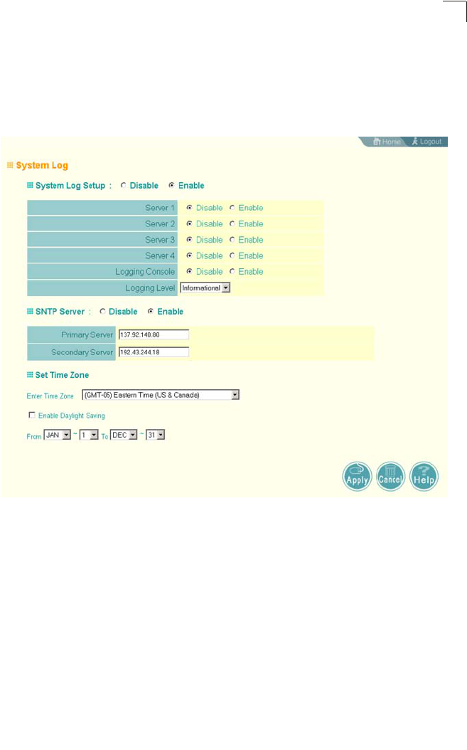
Advanced Configuration
6-33
6
System Log
The access point can be configured to send event and error messages to a System
Log Server. The system clock can also be synchronized with a time server, so that
all the messages sent to the Syslog server are stamped with the correct time and
date.
Enabling System Logging
The access point supports a logging process that can control error messages saved
to memory or sent to a Syslog server. The logged messages serve as a valuable tool
for isolating access point and network problems.
System Log Setup – Enables the logging of error messages. (Default: Disable)
Server (1-4) – Enables the sending of log messages to a Syslog server host. Up to
four Syslog servers are supported on the access point. (Default: Disable)
Server Name/IP – The IP address or name of a Syslog server. (Default: 0.0.0.0)
UDP Port – The UDP port used by a Syslog server. (Range: 514 or 11024-65535;
Default: 514)
Logging Console – Enables the logging of error messages to the console.
(Default: Disable)

System Configuration
6-34
6
Logging Level – Sets the minimum severity level for event logging.
(Default: Informational)
The system allows you to limit the messages that are logged by specifying a
minimum severity level. The following table lists the error message levels from the
most severe (Emergency) to least severe (Debug). The message levels that are
logged include the specified minimum level up to the Emergency level.
Note: The access point error log can be viewed using the Event Logs window in the
Status section (page 6-90). The Event Logs window displays the last 128
messages logged in chronological order, from the newest to the oldest. Log
messages saved in the access point’s memory are erased when the device is
rebooted.
Logging Facility Type – Sets the facility type for remote logging of syslog messages.
The command specifies the facility type tag sent in syslog messages. (See RFC
3164.) This type has no effect on the kind of messages reported by the switch.
However, it may be used by the syslog server to sort messages or to store
messages in the corresponding database. (Range: 16-23; Default: 16)
Error Level Description
Emergency System unusable
Alerts Immediate action needed
Critical Critical conditions (e.g., memory allocation, or free memory error - resource
exhausted)
Error Error conditions (e.g., invalid input, default used)
Warning Warning conditions (e.g., return false, unexpected return)
Notice Normal but significant condition, such as cold start
Informational Informational messages only
Debug Debugging messages

Advanced Configuration
6-35
6
CLI Commands for System Logging – To enable logging on the access point, use
the logging on command from the global configuration mode. The logging level
command sets the minimum level of message to log. Use the logging console
command to enable logging to the console. Use the logging host command to
specify up to four Syslog servers. The CLI also allows the logging facility-type
command to set the facility-type number to use on the Syslog server. To view the
current logging settings, use the show logging command.
Configuring SNTP
Simple Network Time Protocol (SNTP) allows the access point to set its internal
clock based on periodic updates from a time server (SNTP or NTP). Maintaining an
accurate time on the access point enables the system log to record meaningful
dates and times for event entries. If the clock is not set, the access point will only
record the time from the factory default set at the last bootup.
The access point acts as an SNTP client, periodically sending time synchronization
requests to specific time servers. You can configure up to two time server IP
addresses. The access point will attempt to poll each server in the configured
sequence.
SNTP Server – Configures the access point to operate as an SNTP client. When
enabled, at least one time server IP address must be specified.
• Primary Server: The IP address of an SNTP or NTP time server that the access
point attempts to poll for a time update.
• Secondary Server: The IP address of a secondary SNTP or NTP time server. The
access point first attempts to update the time from the primary server; if this fails
it attempts an update from the secondary server.
Enterprise AP(config)#logging on 7-29
Enterprise AP(config)#logging level alert 7-30
Enterprise AP(config)#logging console 7-30
Enterprise AP(config)#logging host 1 IP 10.1.0.3 514 7-29
Enterprise AP(config)#logging host 1 Port 514 7-29
Enterprise AP(config)#logging facility-type 19 7-31
Enterprise AP(config)#exit
Enterprise AP#show logging 7-32
Logging Information
============================================
Syslog State : Enabled
Logging Console State : Enabled
Logging Level : Alert
Logging Facility Type : 19
Servers
1: 10.1.0.3, UDP Port: 514, State: Enabled
2: 0.0.0.0, UDP Port: 514, State: Disabled
3: 0.0.0.0, UDP Port: 514, State: Disabled
4: 0.0.0.0, UDP Port: 514, State: Disabled
=============================================
Enterprise AP#

System Configuration
6-36
6
Note: The access point also allows you to disable SNTP and set the system clock
manually.
Set Time Zone – SNTP uses Coordinated Universal Time (or UTC, formerly
Greenwich Mean Time, or GMT) based on the time at the Earth’s prime meridian,
zero degrees longitude. To display a time corresponding to your local time, you must
indicate the number of hours your time zone is located before (east) or after (west)
UTC.
Enable Daylight Saving – The access point provides a way to automatically adjust
the system clock for Daylight Savings Time changes. To use this feature you must
define the month and date to begin and to end the change from standard time.
During this period the system clock is set back by one hour.
CLI Commands for SNTP – To enable SNTP support on the access point, from the
global configuration mode specify SNTP server IP addresses using the sntp-server
ip command, then use the sntp-server enable command to enable the service. Use
the sntp-server timezone command to set the time zone for your location, and the
sntp-server daylight-saving command to set daylight savings. To view the current
SNTP settings, use the show sntp command.
Enterprise AP(config)#sntp-server ip 1 10.1.0.19 7-34
Enterprise AP(config)#sntp-server enable 7-34
Enterprise AP(config)#sntp-server timezone +8 7-36
Enterprise AP(config)#sntp-server daylight-saving 7-36
Enter Daylight saving from which month<1-12>: 3
and which day<1-31>: 31
Enter Daylight saving end to which month<1-12>: 10
and which day<1-31>: 31
Enterprise AP(config)#exit
Enterprise AP#show sntp 7-37
SNTP Information
=========================================================
Service State : Enabled
SNTP (server 1) IP : 10.1.10.19
SNTP (server 2) IP : 192.43.244.18
Current Time : 19 : 35, Oct 10th, 2003
Time Zone : +8 (TAIPEI, BEIJING)
Daylight Saving : Enabled, from Mar, 31st to Oct, 31st
=========================================================
Enterprise AP#

SNMP
6-37
6
CLI Commands for the System Clock – The following example shows how to
manually set the system time when SNTP server support is disabled on the access
point.
RSSI
The RSSI page displays the ambient noise floor for both radios A and G. These
values only apply to external used antennas. The displayed values are
non-configurable.
dBm – Decibel referenced to milliwatts.
SNMP
Simple Network Management Protocol (SNMP) is a communication protocol
designed specifically for managing devices on a network. Equipment commonly
managed with SNMP includes switches, routers and host computers. SNMP is
typically used to configure these devices for proper operation in a network
environment, as well as to monitor them to evaluate performance or detect potential
problems.
Managed devices supporting SNMP contain software, which runs locally on the
device and is referred to as an agent. A defined set of variables, known as managed
objects, is maintained by the SNMP agent and used to manage the device. These
objects are defined in a Management Information Base (MIB) that provides a
standard presentation of the information controlled by the agent. SNMP defines both
the format of the MIB specifications and the protocol used to access this information
over the network.
Enterprise AP(config)#no sntp-server enable 7-34
Enterprise AP(config)#sntp-server date-time 7-35
Enter Year<1970-2100>: 2003
Enter Month<1-12>: 10
Enter Day<1-31>: 10
Enter Hour<0-23>: 18
Enter Min<0-59>: 35
Enterprise AP(config)#
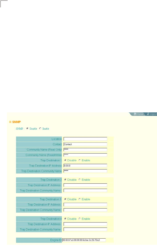
System Configuration
6-38
6
The access point includes an onboard agent that supports SNMP versions 1, 2c,
and 3 clients. This agent continuously monitors the status of the access point, as
well as the traffic passing to and from wireless clients. A network management
station can access this information using SNMP management software that is
compliant with MIB II. To implement SNMP management, the access point must first
have an IP address and subnet mask, configured either manually or dynamically.
Access to the onboard agent using SNMP v1 and v2c is controlled by community
strings. To communicate with the access point, the management station must first
submit a valid community string for authentication.
Access to the access point using SNMP v3 provides additional security features that
cover message integrity, authentication, and encryption; as well as controlling
notifications that are sent to specified user targets.
Configuring SNMP and Trap Message Parameters
The access point SNMP agent must be enabled to function (for versions 1, 2c, and
3 clients). Management access using SNMP v1 and v2c also requires community
strings to be configured for authentication. Trap notifications can be enabled and
sent to up to four management stations.

SNMP
6-39
6
SNMP – Enables or disables SNMP management access and also enables the
access point to send SNMP traps (notifications). (Default: Disable)
Location – A text string that describes the system location. (Maximum length: 255
characters)
Contact – A text string that describes the system contact. (Maximum length: 255
characters)
Community Name (Read Only) – Defines the SNMP community access string that
has read-only access. Authorized management stations are only able to retrieve
MIB objects. (Maximum length: 23 characters, case sensitive; Default: public)
Community Name (Read/Write) – Defines the SNMP community access string that
has read/write access. Authorized management stations are able to both retrieve
and modify MIB objects. (Maximum length: 23 characters, case sensitive;
Default: private)
Trap Destination (1 to 4) – Enables recipients (up to four) of SNMP notifications.
• Trap Destination IP Address – Specifies the recipient of SNMP notifications. Enter
the IP address or the host name. (Host Name: 1 to 63 characters, case sensitive)
• Trap Destination Community Name – The community string sent with the
notification operation. (Maximum length: 23 characters, case sensitive;
Default: public)
Engine ID – Sets the engine identifier for the SNMPv3 agent that resides on the
access point. This engine protects against message replay, delay, and redirection.
The engine ID is also used in combination with user passwords to generate the
security keys for authenticating and encrypting SNMPv3 packets. A default engine
ID is automatically generated that is unique to the access point. (Range: 10 to 64
hexadecimal characters)
Note: If the local engine ID is deleted or changed, all SNMP users will be cleared. All
existing users will need to be re-configured. If you want to change the default
engine ID, change it first before configuring other SNMP v3 parameters.
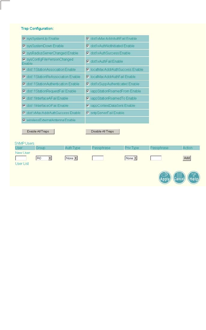
System Configuration
6-40
6
Trap Configuration – Allows selection of specific SNMP notifications to send. The
following items are available:
• sysSystemUp - The access point is up and running.
• sysSystemDown - The access point is about to shutdown and reboot.
• sysRadiusServerChanged - The access point has changed from the primary
RADIUS server to the secondary, or from the secondary to the primary.
• sysConfigFileVersionChanged - The access point’s configuration file has been
changed.
• dot11StationAssociation - A client station has successfully associated with the
access point.
• dot11StationReAssociation - A client station has successfully re-associated with
the access point.
• dot11StationAuthentication - A client station has been successfully authenticated.
• dot11StationRequestFail - A client station has failed association, re-association,
or authentication.
• dot11InterfaceBFail - The 802.11b interface has failed.
• dot11InterfaceAGFail - The 802.11a or 802.11g interface has failed.
• dot1xMacAddrAuthSuccess - A client station has successfully authenticated its
MAC address with the RADIUS server.

SNMP
6-41
6
• dot1xMacAddrAuthFail - A client station has failed MAC address authentication
with the RADIUS server.
• dot1xAuthNotInitiated - A client station did not initiate 802.1X authentication.
• dot1xAuthSuccess - A 802.1X client station has been successfully authenticated
by the RADIUS server.
• dot1xAuthFail - A 802.1X client station has failed RADIUS authentication.
• localMacAddrAuthSuccess - A client station has successfully authenticated its
MAC address with the local database on the access point.
• localMacAddrAuthFail - A client station has failed authentication with the local
MAC address database on the access point.
• iappStationRoamedFrom - A client station has roamed from another access point
(identified by its IP address).
• iappStationRoamedTo - A client station has roamed to another access point
(identified by its IP address).
• iappContextDataSent - A client station’s Context Data has been sent to another
access point with which the station has associated.
• sntpServerFail - The access point has failed to set the time from the configured
SNTP server.
• Enable All Traps - Click the button to enable all the available traps.
• Disable All Traps - Click the button to disable all the available traps.
CLI Commands for SNMP and Trap Configuration – Use the snmp-server enable
server command from the global configuration mode to enable the SNMP agent.
Use the snmp-server location and snmp-server contact commands to indicate
the physical location of the access point and define a system contact. To set the
read-only and read/write community names, use the snmp-server community
command. Use the snmp-server host command to define a trap receiver host and
the snmp-server trap command to enable or disable specific traps.
Enterprise AP(config)#snmp-server enable server 7-42
Enterprise AP(config)#snmp-server community alpha rw 7-41
Enterprise AP(config)#snmp-server community beta ro
Enterprise AP(config)#snmp-server location WC-19 7-42
Enterprise AP(config)#snmp-server contact Paul 7-41
Enterprise AP(config)#snmp-server host 192.168.1.9 alpha 7-43
Enterprise AP(config)#snmp-server trap dot11StationAssociation 7-44
Enterprise AP(config)#

System Configuration
6-42
6
To view the current SNMP settings, use the show snmp command.
Configuring SNMPv3 Users
The access point allows up to 10 SNMP v3 users to be configured. Each user must
be defined by a unique name, assigned to one of three pre-defined security groups,
and configured with specific authentication and encryption settings.
User – The SNMPv3 user name. (32 characters maximum)
Group – The SNMPv3 group name. (Options: RO, RWAuth, or RWPriv; Default: RO)
• RO – Read-only access.
• RWAuth – Read/write access with user authentication.
• RWPriv – Read/write access with both user authentication and data encryption.
Auth Type – The authentication type used for the SNMP user; either MD5 or none.
When MD5 is selected, enter a password in the corresponding Passphrase field.
Priv Type – The data encryption type used for the SNMP user; either DES or none.
When DES is selected, enter a key in the corresponding Passphrase field.
Enterprise AP#show snmp 7-54
SNMP Information
==============================================
Service State : Enable
Community (ro) : *****
Community (rw) : *****
Location : WC-19
Contact : Paul
EngineId :80:00:07:e5:80:00:00:2e:62:00:00:00:18
EngineBoots:1
Trap Destinations:
1: 192.168.1.9, Community: *****, State: Enabled
2: 0.0.0.0, Community: *****, State: Disabled
3: 0.0.0.0, Community: *****, State: Disabled
4: 0.0.0.0, Community: *****, State: Disabled
dot11InterfaceAGFail Enabled dot11InterfaceBFail Enabled
dot11StationAssociation Enabled dot11StationAuthentication Enabled
dot11StationReAssociation Enabled dot11StationRequestFail Enabled
dot1xAuthFail Enabled dot1xAuthNotInitiated Enabled
dot1xAuthSuccess Enabled dot1xMacAddrAuthFail Enabled
dot1xMacAddrAuthSuccess Enabled iappContextDataSent Enabled
iappStationRoamedFrom Enabled iappStationRoamedTo Enabled
localMacAddrAuthFail Enabled localMacAddrAuthSuccess Enabled
pppLogonFail Enabled sntpServerFail Enabled
configFileVersionChanged Enabled radiusServerChanged Enabled
systemDown Enabled systemUp Enabled
=============================================
Enterprise AP#

SNMP
6-43
6
Passphrase – The password or key associated with the authentication and privacy
settings. A minimum of eight plain text characters is required.
Action – Click the Add button to add a new user to the list. Click the edit button to
change details of an existing user. Click the Del button to remove a user from the list.
Note: Users must be assigned to groups that have the same security levels. For
example, a user who has “Auth Type” and “Priv Type” configured to MD5 and
DES respectively (that it, uses both authentication and data encryption) must be
assigned to the RWPriv group. If this same user were instead assigned to the
read-only (RO) group, the user would not be able to access the database.
CLI Commands for Configuring SNMPv3 Users – Use the snmp-server engine-id
command to define the SNMP v3 engine before assigning users to groups. Use the
snmp-server user command to assign users to one of the three groups and set the
appropriate authentication and encryption types to be used. To view the current
SNMP v3 engine ID, use the show snmp command. To view SNMP users and
group settings, use the show snmp users or show snmp group-assignments
commands.
Enterprise AP(config)#snmp-server engine-id 1a:2b:3c:4d:00:ff 7-45
Enterprise AP(config)#snmp-server user 7-46
User Name<1-32> :chris
Group Name<1-32> :RWPriv
Authtype(md5,<cr>none):md5
Passphrase<8-32>:a good secret
Privacy(des,<cr>none) :des
Passphrase<8-32>:a very good secret
Enterprise AP(config)#exit
Enterprise AP#show snmp users 7-51
=============================================
UserName :chris
GroupName :RWPriv
AuthType :MD5
Passphrase:****************
PrivType :DES
Passphrase:****************
=============================================
Enterprise AP#show snmp group-assignments 7-51
GroupName :RWPriv
UserName :chris
Enterprise AP#
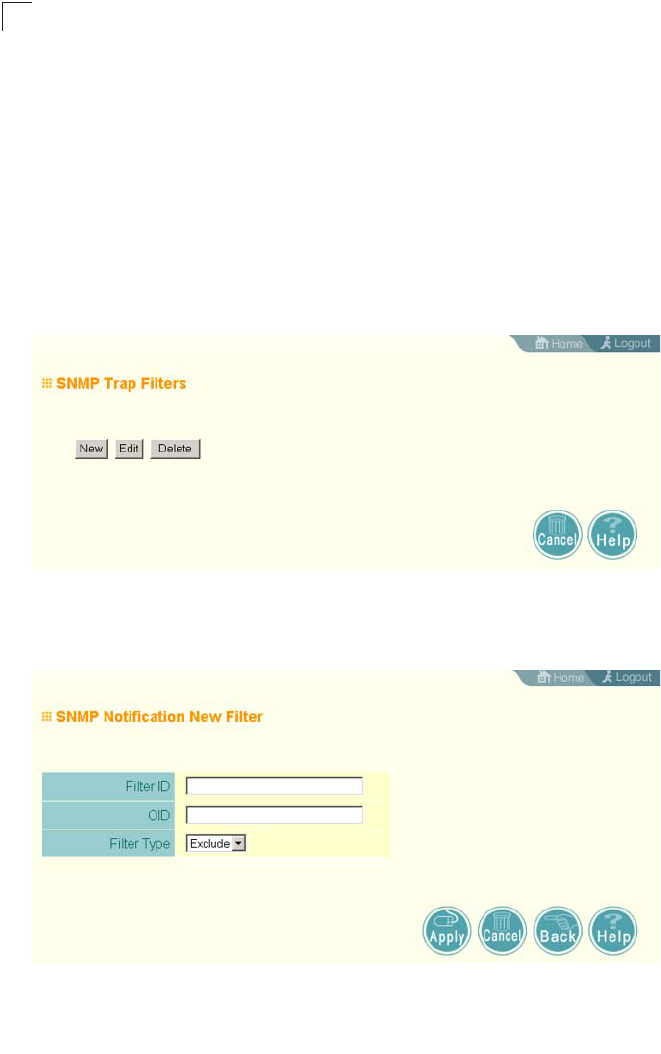
System Configuration
6-44
6
Configuring SNMPv3 Trap Filters
SNMP v3 users can be configured to receive notification messages from the access
point. An SNMP Target ID is created that specifies the SNMP v3 user, IP address,
and UDP port. A user-defined notification filter can be created so that specific
notifications can be prevented from being sent to particular targets.
The access point allows up to 10 notification filters to be created. Each filter can be
defined by up to 20 MIB subtree ID entries.
To configure a new notification filter, click the New button. A new page opens to
configure the filter (see below). To edit an existing filter, select the radio button next
to the entry in the table and then click the Edit button. To delete a filter, select the
radio button next to the entry in the table and then click the Delete button.
When you click on the New button in the SNMP Trap Filters page, a new page
opens where the filter parameters are configured. Define a filter name, subtree ID to
be filtered, and a mask if required. Select the filter type, include or exclude, from the
drop-down list. Click Apply to create the filter.
To add more subtree IDs to the filter, return to the SNMP Trap Filters page and click
the Edit button. In the Edit page, click the New button to access the Add SNMP
Notification Subtree page and configure a new subtree ID to be filtered.

SNMP
6-45
6
Note: Only the New Filter page allows the Filter ID to be configured.
Filter ID – A user-defined name that identifies the filter. (Maximum length: 32
characters)
Subtree OID – Specifies MIB subtree to be filtered. The MIB subtree must be
defined in the form “.1.3.6.1” and always start with a “.”.
Subtree Mask – A hexadecimal value with each bit masking the corresponding ID in
the MIB subtree. A “1” in the mask indicates an exact match and a “0” indicates a
“wild card.” For example, a mask value of 0xFFBF provides a bit mask “1111 1111
1011 1111.” If applied to the subtree “1.3.6.1.2.1.2.2.1.1.23,” the zero corresponds to
the 10th subtree ID. When there are more subtree IDs than bits in the mask, the
mask is padded with ones.
Filter Type – Indicates if the filter is to “include” or “exclude” the MIB subtree objects
from the filter. Note that MIB objects included in the filter are not sent to the receiving
target and objects excluded are sent. By default all traps are sent, so you can first
use an “include” filter entry for all trap objects. Then use “exclude” entries for the
required trap objects to send to the target. Note that the filter entries are applied in
the sequence that they are defined.

System Configuration
6-46
6
CLI Commands for Configuring SNMPv3 Trap Filters – To create a notification filter,
use the snmp-server filter command from the CLI configuration mode. Use the
command more than once with the same filter ID to build a filter that includes or
excludes multiple MIB objects. To view the current SNMP filters, use the show
snmp filter command from the CLI Exec mode.
Configuring SNMPv3 Targets
An SNMP v3 notification Target ID is specified by the SNMP v3 user, IP address,
and UDP port. A user-defined filter can also be assigned to specific targets to limit
the notifications received to specific MIB objects. (Note that the filter must first be
configured. see “Configuring SNMPv3 Trap Filters” on page 6-44)
To configure a new notification receiver target, click the New button. A new page
opens to configure the settings (see below). To edit an existing target, select the
radio button next to the entry in the table and then click the Edit button. To delete
targets, select the radio button next to the entry in the table and then click the Delete
button.
When you click on the New or Edit button in the SNMP Targets page, a new page
opens where the target parameters are configured. Define the parameters and
select a filter, if required. Note that the SNMP v3 user name must first be defined
(see “Configuring SNMPv3 Users” on page 6-42). Click Apply.
Enterprise AP(config)#snmp-server filter trapfilter
include .1 7-49
Enterprise AP(config)#snmp-server filter trapfilter
exclude .1.3.6.1.2.1.2.2.1.1.23
Enterprise AP(config)#exit
Enterprise AP#show snmp filter 7-52
Filter: trapfilter
Type: include
Subtree: iso
Type: exclude
Subtree: iso.3.6.1.2.1.2.2.1.1.23
=============================
Enterprise AP#
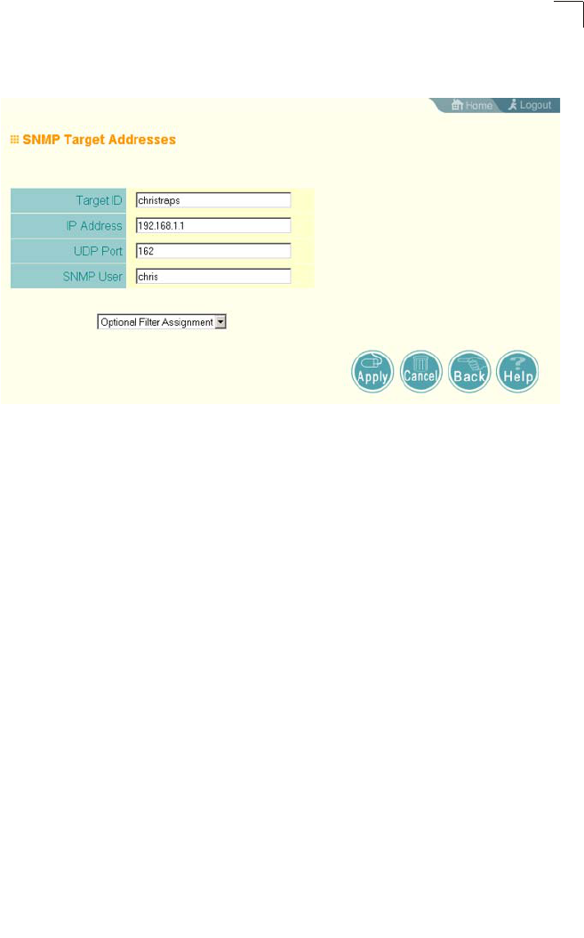
SNMP
6-47
6
Note: The Target ID cannot be changed in the Edit Target page. Only the New Target
page allows the Target ID to be configured.
Target ID – A user-defined name that identifies a receiver of notifications. The
access point supports up to 10 target IDs. (Maximum length: 32 characters)
IP Address – Specifies the IP address of the receiving management station.
UDP Port – The UDP port that is used on the receiving management station for
notification messages.
SNMP User – The defined SNMP v3 user that is to receive notification messages.
Assigned Filter – The name of a user-defined notification filter that is applied to the
target.
CLI Commands for Configuring SNMPv3 Targets – To create a notification target,
use the snmp-server targets command from the CLI configuration mode. To assign
a filter to a target, use the snmp-server filter-assignment command. To view the
current SNMP targets, use the show snmp target command from the CLI Exec
mode. To view filter assignment to targets, use the show snmp filter-assignments
command.

System Configuration
6-48
6
Radio Interface
The IEEE 802.11a and 802.11g interfaces include configuration options for radio
signal characteristics and wireless security features. The configuration options are
nearly identical, and are therefore both covered in this section of the manual.
The access point can operate in three modes, IEEE 802.11a only, 802.11b/g only, or
a mixed 802.11a/b/g mode. Also note that 802.11g is backward compatible with
802.11b. These interfaces are configured independently under the following web
pages:
• Radio Interface A: 802.11a
• Radio Interface G: 802.11b/g
Each radio supports up to four virtual access point (VAP) interfaces numbered 0 to
3. Each VAP functions as a separate access point, and can be configured with its
own Service Set Identification (SSID) and security settings. However, most radio
signal parameters apply to all four VAP interfaces.
The VAPs function similar to a VLAN, with each VAP mapped to its own VLAN ID.
Traffic to specific VAPs can segregated based on user groups or application traffic.
Each VAP can have up to 64 wireless clients, whereby the clients associate with
these VAPs the same as they would with a physical access point.
Note: The radio channel settings for the access point are limited by local regulations,
which determine the number of channels that are available. Refer to “General
Specifications” on page C-1 for additional information on the maximum number
channels available.
Enterprise AP(config)#snmp-server targets mytraps
192.168.1.33 chris 7-48
Enterprise AP(config)#snmp-server filter-assignment
mytraps trapfilter 7-50
Enterprise AP(config)#exit
Enterprise AP#show snmp target 7-52
Host ID : mytraps
User : chris
IP Address : 192.168.1.33
UDP Port : 162
=============================
Enterprise AP#show snmp filter-assignments 7-53
HostID FilterID
mytraps trapfilter
Enterprise AP#
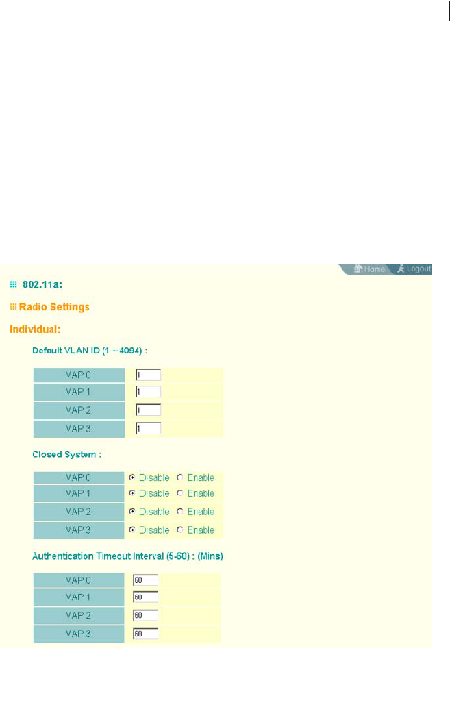
Radio Interface
6-49
6
Radio Settings A (802.11a)
The IEEE 802.11a interface operates within the 5 GHz band, at up to 54 Mbps in
normal mode or up to 108 Mbps in Turbo mode.
First configure the radio settings that apply to the individual VAPs (Virtual Access
Point) and the common radio settings that apply to the overall system. After you
have configured the radio settings, go to the Security page under the 802.a Interface
(see “Security” on page 6-66), enable the radio service for any of the VAP interfaces,
and then set an SSID to identify the wireless network service provided by each VAP.
Remember that only clients with the same SSID can associate with a VAP.
Note: You must first enable VAP interface 0 before the other interfaces can be enabled.
Configuring VAP Radio Settings
To configure VAP radio settings, select the Radio Settings page.

System Configuration
6-50
6
Default VLAN ID – The VLAN ID assigned to wireless clients associated to the VAP
interface that are not assigned to a specific VLAN by RADIUS server configuration.
(Default: 1)
Closed System – When enabled, the VAP interface does not include its SSID in
beacon messages. Nor does it respond to probe requests from clients that do not
include a fixed SSID. (Default: Disable)
Authentication Timeout Interval – The time within which the client should finish
authentication before authentication times out. (Range: 5-60 minutes; Default: 60
minutes)
Association Timeout Interval – The idle time interval (when no frames are sent) after
which a client is disassociated from the VAP interface. (Range: 5-60 minutes;
Default: 30 minutes)
WPA2 PMKSA Life Time – WPA2 provides fast roaming for authenticated clients by
retaining keys and other security settings in a cache for each VAP. In this way, when
clients roam back into a VAP they had previously been using, re-authentication is
not required. When a WPA2 client is first authenticated, it receives a Pairwise
Master Key (PMK) that is used to generate the other keys used for unicast data
encryption. This key and other client information form a client Security Association
(SA) that the VAP holds in a cache. When the lifetime expires, the security
association and keys are deleted from the cache. If the client returns to an access
point after the association has been deleted, it will require full re-authentication.
(Range: 1-1440 minutes; Default: 720 minutes)
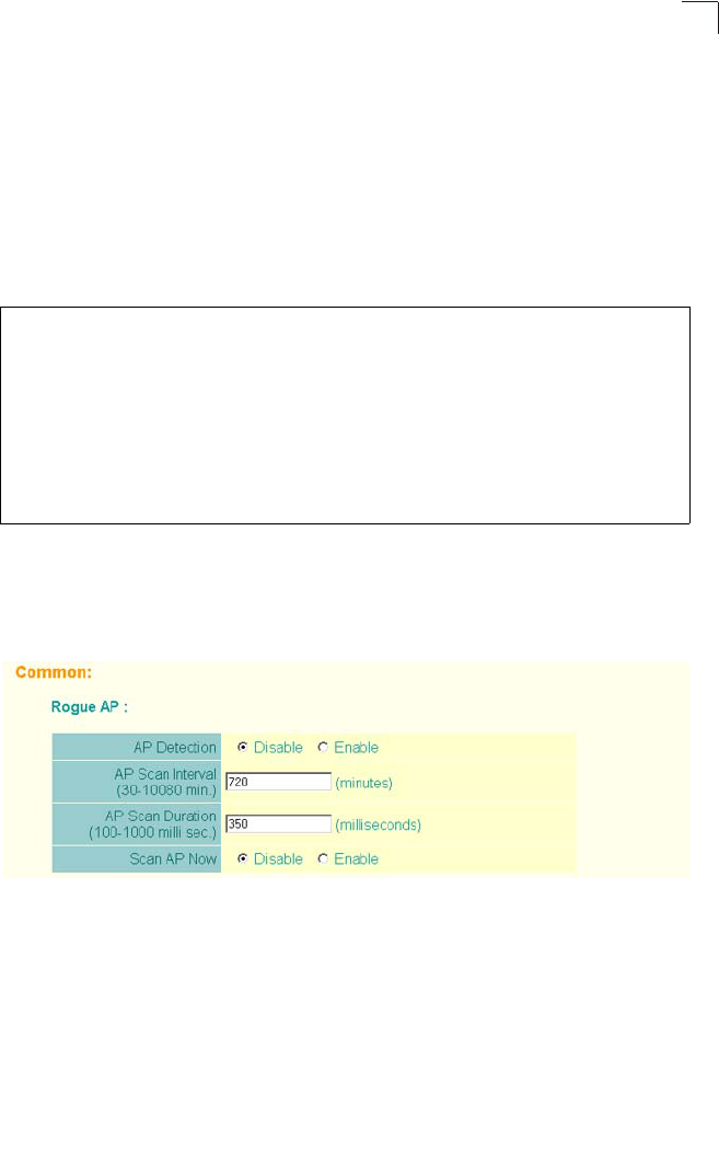
Radio Interface
6-51
6
CLI Commands for the Configuring the VAPs – From the global configuration mode,
enter the interface wireless a command to access the 802.11a radio interface.
From the 802.11a interface mode, you can access radio settings that apply to all
VAP interfaces. To access a specific VAP interface (numbered 0 to 3), use the vap
command. You can configure a name for each interface using the description
command. You can also use the closed-system command to stop sending the
SSID in beacon messages. Set any other VAP parameters and radio setting as
required before enabling the VAP interface (with the no shutdown command). To
view the current 802.11a radio settings for the VAP interface, use the show
interface wireless a 0 command as shown on 7-94.
Configuring Rogue AP Detection
To configure Rouge AP detection, select the Radio Settings page, and scroll down to
the “Rouge AP” section.
Rogue AP – A “rogue AP” is either an access point that is not authorized to
participate in the wireless network, or an access point that does not have the correct
security configuration. Rogue APs can allow unauthorized access to the network, or
fool client stations into mistakenly associating them and thereby blocking access to
network resources.
Enterprise AP(if-wireless a)#vap 0 7-94
Enterprise AP(if-wireless a: VAP[0])#description RD-AP#3 7-105
Enterprise AP(if-wireless a: VAP[0])#vlan-id 1 7-131
Enterprise AP(if-wireless a: VAP[0])#closed-system 7-106
Enterprise AP(if-wireless a: VAP[0])#authentication-timeout-
interval 30 7-107
Enterprise AP(if-wireless a: VAP[0])#association-timeout-
interval 20 7-107
Enterprise AP(if-wireless a: VAP[0])#max-association 32 7-106
Enterprise AP(if-wireless a: VAP[0])#pmksa-lifetime 900 7-123
Enterprise AP(if-wireless a: VAP[0])#

System Configuration
6-52
6
The access point can be configured to periodically scan all radio channels and find
other access points within range. A database of nearby access points is maintained
where any rogue APs can be identified. During a scan, Syslog messages (see
“Enabling System Logging” on page 6-33) are sent for each access point detected.
Rogue access points can be identified by unknown BSSID (MAC address) or SSID
configuration.
• AP Detection – Enables the periodic scanning for other access points.
(Default: Disable)
• AP Scan Interval – Sets the time between each rogue AP scan. (Range: 30 -10080
minutes; Default: 720 minutes)
• AP Scan Duration – Sets the length of time for each rogue AP scan. A long scan
duration time will detect more access points in the area, but causes more
disruption to client access. (Range: 100 -1000 milliseconds; Default: 350
milliseconds)
• Rogue AP Authenticate – Enables or disables RADIUS authentication. Enabling
RADIUS Authentication allows the access point to discover rogue access points.
With RADIUS authentication enabled, the access point checks the MAC address/
Basic Service Set Identifier (BSSID) of each access point that it finds against a
RADIUS server to determine whether the access point is allowed. With RADIUS
authentication disabled, the access point can identify its neighboring access
points only; it cannot identify whether the access points are allowed or are rogues.
If you enable RADIUS authentication, you must configure a RADIUS server for this
access point (see “RADIUS” on page 6-7).
• Scan AP Now – Starts an immediate rogue AP scan on the radio interface.
(Default: Disable)
Note: While the access point scans a channel for rogue APs, wireless clients will not be
able to connect to the access point. Therefore, avoid frequent scanning or scans
of a long duration unless there is a reason to believe that more intensive scanning
is required to find a rogue AP.
CLI Commands for Rogue AP Detection – From the global configuration mode,
enter the interface wireless command to access the 802.11a or 802.11g radio
interface. From the wireless interface mode, use the rogue-ap enable command to
enable rogue AP detection. Set the duration and interval times with the rogue-ap
duration and rogue-ap interval commands. If required, start an immediate scan

Radio Interface
6-53
6
using the rogue-ap scan command. To view the database of detected access
points, use the show rogue-ap command from the Exec level.
Enterprise AP(config)#interface wireless g 7-87
Enter Wireless configuration commands, one per line.
Enterprise AP(if-wireless g)#rogue-ap enable 7-111
configure either syslog or trap or both to receive the rogue APs detected.
Enterprise AP(if-wireless g)#rogue-ap duration 200 7-113
Enterprise AP(if-wireless g)#rogue-ap interval 120 7-113
Enterprise AP(if-wireless g)#rogue-ap scan 7-114
Enterprise AP(if-wireless g)#rogueApDetect Completed (Radio G) : 5 APs
detected
rogueAPDetect (Radio G): refreshing ap database now
Enterprise AP(if-wireless g)#exit
Enterprise AP#show rogue-ap 7-115
802.11a Channel : Rogue AP Status
AP Address(BSSID) SSID Channel(MHz) RSSI
=======================================================
802.11g Channel : Rogue AP Status
AP Address(BSSID) SSID Channel(MHz) RSSI
=======================================================
00-04-e2-2a-37-23 WLAN1AP 11(2462 MHz) 17
00-04-e2-2a-37-3d ANY 7(2442 MHz) 42
00-04-e2-2a-37-49 WLAN1AP 9(2452 MHz) 42
00-90-d1-08-9d-a7 WLAN1AP 1(2412 MHz) 12
00-30-f1-fb-31-f4 WLAN 6(2437 MHz) 16
Enterprise AP#
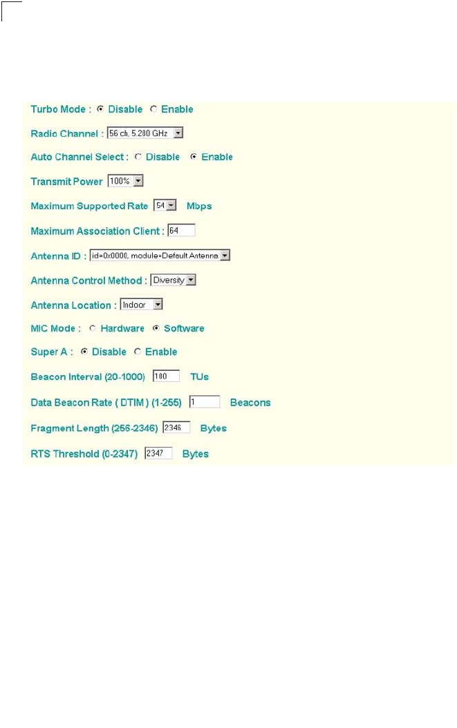
System Configuration
6-54
6
Configuring Common Radio Settings
To configure Rouge AP detection, select the Radio Settings page, and scroll down to
the “Rouge AP” section.
Turbo Mode – The normal 802.11a wireless operation mode provides connections
up to 54 Mbps. Turbo Mode is an enhanced mode (not regulated in IEEE 802.11a)
that provides a higher data rate of up to 108 Mbps. Enabling Turbo Mode allows the
access point to provide connections up to 108 Mbps. (Default: Disabled)
Note: Note: In normal mode, the access point provides a channel bandwidth of 20 MHz,
and supports the maximum number of channels permitted by local regulations
(e.g., 13 channels for the United States). In Turbo Mode, the channel bandwidth is
increased to 40 MHz to support the increased data rate. However, this reduces
the number of channels supported (e.g., 5 channels for the United States).
Note: Check your country’s regulations to see if Turbo Mode is allowed.
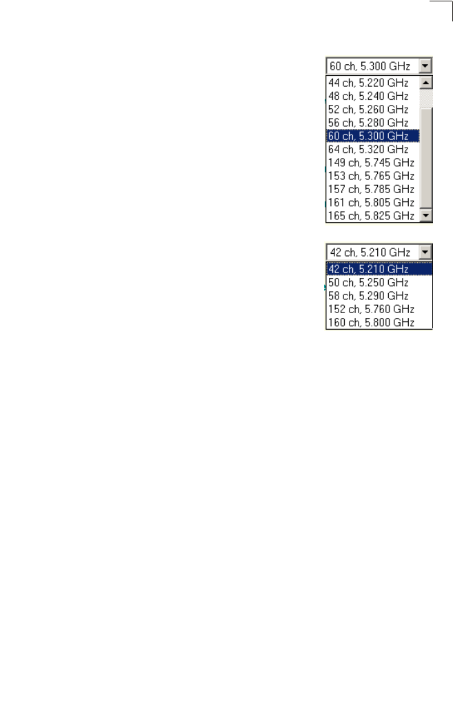
Radio Interface
6-55
6
Radio Channel – The radio channel that the access point uses
to communicate with wireless clients. When multiple access
points are deployed in the same area, set the channel on
neighboring access points at least four channels apart to avoid
interference with each other. For example, in the United States
you can deploy up to four access points in the same area (e.g.,
channels 36, 56, 149, 165). Also note that the channel for
wireless clients is automatically set to the same as that used
by the access point to which it is linked. (Default: Channel 60
for normal mode, and channel 42 for Turbo mode)
Auto Channel Select – Enables the access point to
automatically select an unoccupied radio channel.
(Default: Enabled)
Note: Check your country’s regulations to see if Auto
Channel can be disabled.
Transmit Power – Adjusts the power of the radio signals
transmitted from the access point. The higher the transmission
power, the farther the transmission range. Power selection is
not just a trade off between coverage area and maximum
supported clients. You also have to ensure that high-power signals do not interfere
with the operation of other radio devices in the service area. (Options: 100%, 50%,
25%, 12%, minimum; Default: 100%)
Note: When operating the access point using 5 GHz channels in a European
Community country, the end user and installer are obligated to operate the device
in accordance with European regulatory requirements for Transmit Power Control
(TPC).
Maximum Supported Rate – The maximum data rate at which the access point
transmits unicast packets on the wireless interface. The maximum transmission
distance is affected by the data rate. The lower the data rate, the longer the
transmission distance. (Options: 54, 48, 36, 24 Mbps; Default: 54 Mbps)
Maximum Associated Clients – Sets the maximum number of clients that can be
associated with a VAP interface at the same time. (Range: 1-64 per VAP interface:
Default: 64)
Antenna ID – Selects the antenna to be used by the access point; either the
integrated diversity antennas (the "Default Antenna") or an optional external
antenna. The optional external antennas (if any) that are certified for use with the
access point are listed in the drop-down menu. Selecting the correct antenna ID
ensures that the access point's radio transmissions are within regulatory power
limits for the country of operation. When an external antenna is selected, the
Antenna Control Method must be set to "Right." (Default: Default Antenna)
Note: The Antenna ID must be selected in conjunction with the Antenna Control Method
to configure proper use of any of the antenna options.
Normal Mode
Turbo Mode

System Configuration
6-56
6
Antenna Control Method - Selects the use of both fixed antennas operating in
diversity mode or a single antenna. (Default: Diversity)
• Diversity: The radio uses both antennas in a diversity system. Select this method
when the Antenna ID is set to "Default Antenna" to use the access point's
integrated antennas. The access point does not support external diversity
antennas.
• Right: The radio only uses the antenna on the right side (the side closest to the
access point LEDs). Select this method when using an optional external antenna
that is connected to the right antenna connector.
• Left: The radio only uses the antenna on the left side (the side farthest from the
access point LEDs). The access point does not support an external antenna
connection on its left antenna. Therefore, this method is not valid for the access
point.
Antenna Location – Selects the mounting location of the antenna in use; either
“Indoor” or “Outdoor.” Selecting the correct location ensures that the access point
only uses radio channels that are permitted in the country of operation.
(Default: Indoor)
MIC Mode – The Michael Integrity Check (MIC) is part of the Temporal Key Integrity
Protocol (TKIP) encryption used in Wi-Fi Protected Access (WPA) security. The MIC
calculation is performed in the access point for each transmitted packet and this can
impact throughput and performance. The access point supports a choice of software
or hardware MIC calculation. The performance of the access point can be improved
by selecting the best method for the specific deployment. (Default: Software)
• Hardware: Provides best performance when the number of supported clients is
less than 27.
• Software: Provides the best performance for a large number of clients on one radio
interface. Throughput may be reduced when both 802.11a and 802.11g interfaces
are supporting a high number of clients simultaneously.
Super A – The Atheros proprietary Super A performance enhancements are
supported by the access point. These enhancements include bursting, compression,
and fast frames. Maximum throughput ranges between 40 to 60 Mbps for
connections to Atheros-compatible clients. (Default: Disabled)
Beacon Interval – The rate at which beacon signals are transmitted from the access
point. The beacon signals allow wireless clients to maintain contact with the access
point. They may also carry power-management information.
(Range: 20-1000 TUs; Default: 100 TUs)
Data Beacon Rate – The rate at which stations in sleep mode must wake up to
receive broadcast/multicast transmissions.
Known also as the Delivery Traffic Indication Map (DTIM) interval, it indicates how
often the MAC layer forwards broadcast/multicast traffic, which is necessary to wake
up stations that are using Power Save mode. The default value of 2 indicates that
the access point will save all broadcast/multicast frames for the Basic Service Set

Radio Interface
6-57
6
(BSS) and forward them after every second beacon. Using smaller DTIM intervals
delivers broadcast/multicast frames in a more timely manner, causing stations in
Power Save mode to wake up more often and drain power faster. Using higher DTIM
values reduces the power used by stations in Power Save mode, but delays the
transmission of broadcast/multicast frames.
(Range: 1-255 beacons; Default: 1 beacon)
Multicast Data Rate – The maximum data rate at which the access point transmits
multicast and broadcast packets on the wireless interface. (Options: 24, 12, 6
Mbps; Default: 6 Mbps)
Fragmentation Length – Configures the minimum packet size that can be
fragmented when passing through the access point. Fragmentation of the PDUs
(Package Data Unit) can increase the reliability of transmissions because it
increases the probability of a successful transmission due to smaller frame size. If
there is significant interference present, or collisions due to high network utilization,
try setting the fragment size to send smaller fragments. This will speed up the
retransmission of smaller frames. However, it is more efficient to set the fragment
size larger if very little or no interference is present because it requires overhead to
send multiple frames. (Range: 256-2346 bytes; Default: 2346 bytes)
RTS Threshold – Sets the packet size threshold at which a Request to Send (RTS)
signal must be sent to a receiving station prior to the sending station starting
communications. The access point sends RTS frames to a receiving station to
negotiate the sending of a data frame. After receiving an RTS frame, the station
sends a CTS (clear to send) frame to notify the sending station that it can start
sending data.
If the RTS threshold is set to 0, the access point always sends RTS signals. If set to
2347, the access point never sends RTS signals. If set to any other value, and the
packet size equals or exceeds the RTS threshold, the RTS/CTS (Request to Send /
Clear to Send) mechanism will be enabled.
The access points contending for the medium may not be aware of each other. The
RTS/CTS mechanism can solve this “Hidden Node Problem.” (Range: 0-2347 bytes:
Default: 2347 bytes)

System Configuration
6-58
6
CLI Commands for the Common Radio Settings – From the global configuration
mode, enter the interface wireless a command to access the 802.11a radio
interface. From the 802.11a interface mode, you can access radio settings that apply
to all VAP interfaces. Use the turbo command to enable this feature before setting
the radio channel with the channel command. Set any other radio setting as
required before enabling the VAP interface (with the no shutdown command). To
view the current 802.11a radio settings for the VAP interface, use the show
interface wireless a [0~3] command as shown on 7-94.
Configuring Wi-Fi Multimedia
Wireless networks offer an equal opportunity for all devices to transmit data from
any type of application. Although this is acceptable for most applications, multimedia
applications (with audio and video) are particularly sensitive to the delay and
throughput variations that result from this “equal opportunity” wireless access
method. For multimedia applications to run well over a wireless network, a Quality of
Service (QoS) mechanism is required to prioritize traffic types and provide an
“enhanced opportunity” wireless access method.
The access point implements QoS using the Wi-Fi Multimedia (WMM) standard.
Using WMM, the access point is able to prioritize traffic and optimize performance
when multiple applications compete for wireless network bandwidth at the same
time. WMM employs techniques that are a subset of the developing IEEE 802.11e
QoS standard and it enables the access point to inter operate with both WMM-
enabled clients and other devices that may lack any WMM functionality.
Access Categories — WMM defines four access categories (ACs): voice, video,
best effort, and background. These categories correspond to traffic priority levels
and are mapped to IEEE 802.1D priority tags (see Table 6-1). The direct mapping of
the four ACs to 802.1D priorities is specifically intended to facilitate inter operability
with other wired network QoS policies. While the four ACs are specified for specific
Enterprise AP(config)#interface wireless a 7-87
Enter Wireless configuration commands, one per line.
Enterprise AP(if-wireless a)#turbo 7-95
Enterprise AP(if-wireless a)#channel 42 7-96
Enterprise AP(if-wireless a)#transmit-power full 7-97
Enterprise AP(if-wireless a)#speed 9 7-95
Enterprise AP(if-wireless a)#antenna id 0000 7-100
Enterprise AP(if-wireless a)#antenna control right 7-99
Enterprise AP(if-wireless a)#antenna location indoor 7-100
Enterprise AP(if-wireless a)#mic_mode hardware 7-122
Enterprise AP(if-wireless a)#super-a 7-104
Enterprise AP(if-wireless a)#beacon-interval 150 7-101
Enterprise AP(if-wireless a)#beacon-interval 150 7-101
Enterprise AP(if-wireless a)#dtim-period 5 7-101
Enterprise AP(if-wireless a)#multicast-data-rate 6 7-96
Enterprise AP(if-wireless a)#fragmentation-length 512 7-102
Enterprise AP(if-wireless a)#rts-threshold 256 7-103
Enterprise AP(if-wireless a)#

Radio Interface
6-59
6
types of traffic, WMM allows the priority levels to be configured to match any
network-wide QoS policy. WMM also specifies a protocol that access points can use
to communicate the configured traffic priority levels to QoS-enabled wireless clients.
WMM Operation — WMM uses traffic priority based on the four ACs; Voice, Video,
Best Effort, and Background. The higher the AC priority, the higher the probability
that data is transmitted.
When the access point forwards traffic, WMM adds data packets to four independent
transmit queues, one for each AC, depending on the 802.1D priority tag of the
packet. Data packets without a priority tag are always added to the Best Effort AC
queue. From the four queues, an internal “virtual” collision resolution mechanism
first selects data with the highest priority to be granted a transmit opportunity. Then
the same collision resolution mechanism is used externally to determine which
device has access to the wireless medium.
For each AC queue, the collision resolution mechanism is dependent on two timing
parameters:
• AIFSN (Arbitration Inter-Frame Space Number), a number used to calculate the
minimum time between data frames
• CW (Contention Window), a number used to calculate a random backoff time
After a collision detection, a backoff wait time is calculated. The total wait time is the
sum of a minimum wait time (Arbitration Inter-Frame Space, or AIFS) determined
from the AIFSN, and a random backoff time calculated from a value selected from
zero to the CW. The CW value varies within a configurable range. It starts at CWMin
and doubles after every collision up to a maximum value, CWMax. After a
successful transmission, the CW value is reset to its CWMin value.
Table 6-1. WMM Access Categories
Access Category WMM Designation Description 802.1D Tags
AC_VO (AC3) Voice Highest priority, minimum delay. Time-sensitive
data such as VoIP (Voice over IP) calls. 7, 6
AC_VI (AC2) Video High priority, minimum delay. Time-sensitive data
such as streaming video. 5, 4
AC_BE (AC0) Best Effort Normal priority, medium delay and throughput.
Data only affected by long delays. Data from
applications or devices that lack QoS capabilities.
0, 3
AC_BK (AC1) Background Lowest priority. Data with no delay or throughput
requirements, such as bulk data transfers. 2, 1
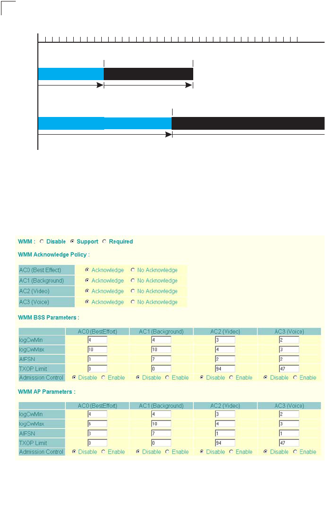
System Configuration
6-60
6
Figure 6-1. WMM Backoff Wait Times
For high-priority traffic, the AIFSN and CW values are smaller. The smaller values
equate to less backoff and wait time, and therefore more transmit opportunities.
To configure WMM, select the Radio Settings page, and scroll down to the WMM
configuration settings.
AIFS Random Backoff
AIFS Random Backoff
CWMin CWMax
CWMin
C
Ti
m
r
iority
r
iority
Minimum Wait Time Random Wait Time
Minimum Wait Time Random Wait Time

Radio Interface
6-61
6
WMM – Sets the WMM operational mode on the access point. When enabled, the
parameters for each AC queue will be employed on the access point and QoS
capabilities are advertised to WMM-enabled clients. (Default: Support)
• Disable: WMM is disabled.
• Support: WMM will be used for any associated device that supports this feature.
Devices that do not support this feature may still associate with the access point.
• Required: WMM must be supported on any device trying to associated with the
access point. Devices that do not support this feature will not be allowed to
associate with the access point.
WMM Acknowledge Policy – By default, all wireless data transmissions require the
sender to wait for an acknowledgement from the receiver. WMM allows the
acknowledgement wait time to be turned off for each Access Category (AC).
Although this increases data throughput, it can also result in a high number of errors
when traffic levels are heavy. (Default: Acknowledge)
WMM BSS Parameters – These parameters apply to the wireless clients.
WMM AP Parameters – These parameters apply to the access point.
• logCWMin (Minimum Contention Window) – The initial upper limit of the random
backoff wait time before wireless medium access can be attempted. The initial
wait time is a random value between zero and the CWMin value. Specify the
CWMin value in the range 0-15 microseconds. Note that the CWMin value must
be equal or less than the CWMax value.
• logCWMax (Maximum Contention Window) – The maximum upper limit of the
random backoff wait time before wireless medium access can be attempted. The
contention window is doubled after each detected collision up to the CWMax
value. Specify the CWMax value in the range 0-15 microseconds. Note that the
CWMax value must be greater or equal to the CWMin value.
• AIFS (Arbitration Inter-Frame Space) – The minimum amount of wait time before
the next data transmission attempt. Specify the AIFS value in the range
0-15 microseconds.
• TXOP Limit (Transmit Opportunity Limit) – The maximum time an AC transmit
queue has access to the wireless medium. When an AC queue is granted a
transmit opportunity, it can transmit data for a time up to the TxOpLimit. This data
bursting greatly improves the efficiency for high data-rate traffic. Specify a value
in the range 0-65535 microseconds.
• Admission Control – The admission control mode for the access category. When
enabled, clients are blocked from using the access category. (Default: Disabled)
Key Type – See “Wired Equivalent Privacy (WEP)” on page 6-71.
CLI Commands for WMM – Enter interface wireless mode and type wmm required
for clients that want to associate with the access point. The
wmm-acknowledge-policy command is used to enable or disable a policy for each
access category. The wmmparms command defines detailed WMM parameters.

System Configuration
6-62
6
To view the current 802.11a radio settings for the VAP interface, use the show
interface wireless a 0 command.
Enterprise AP(if-wireless a)#wmm required
Enterprise AP(if-wireless a)#wmm-acknowledge-policy 0 noack
Enterprise AP(if-wireless a)#wmmparams ap 0 4 6 3 1 1
Enterprise AP#show interface wireless a 0 7-109
Wireless Interface Information
=============================================================
--------------------Identification---------------------------
Description : SMC 802.11g Access Point
SSID : SMC_A 0
Turbo Mode : DISABLED
Channel : 36 (AUTO)
Status : DISABLED
MAC Address : 00:12:cf:05:95:0c
----------------802.11 Parameters---------------------------
Transmit Power : FULL (16 dBm)
Max Station Data Rate : 54Mbps
Multicast Data Rate : 6Mbps
Fragmentation Threshold : 2346 bytes
RTS Threshold : 2347 bytes
Beacon Interval : 100 TUs
Authentication Timeout Interval : 60 Mins
Association Timeout Interval : 30 Mins
DTIM Interval : 1 beacon
Maximum Association : 64 stations
MIC Mode : Software
Super A : Disabled
VLAN ID : 1
----------------Security-------------------------------------
Closed System : Disabled
Multicast cipher : WEP
WPA clients : TKIP and AES
WPA Key Mgmt Mode : PRE SHARED KEY
WPA PSK Key Type : PASSPHRASE
Encryption : DISABLED
Default Transmit Key : 1
Common Static Keys : Key 1: EMPTY Key 2: EMPTY
Key 3: EMPTY Key 4: EMPTY
Authentication Type : OPEN
----------------802.1x---------------------------------------
802.1x :
Broadcast Key Refresh Rate : 30 min
Session Key Refresh Rate : 30 min
802.1x Session Timeout Value : 0 min
----------------Antenna--------------------------------------
Antenna Control method : Diversity
Antenna ID : 0x0000(Default Antenna)
Antenna Location : Indoor

Radio Interface
6-63
6
Radio Settings G (802.11g)
The IEEE 802.11g standard operates within the 2.4 GHz band at up to 54 Mbps.
Also note that because the IEEE 802.11g standard is an extension of the IEEE
802.11b standard, it allows clients with 802.11b wireless network cards to associate
to an 802.11g access point.
First configure the radio settings that apply to the individual VAPs (Virtual Access
Point) and the common radio settings that apply to the overall system. After you
have configured the radio settings, go to the Security page under the 802.a Interface
(see “Security” on page 6-66), enable the radio service for any of the VAP interfaces,
and then set an SSID to identify the wireless network service provided by each VAP.
Remember that only clients with the same SSID can associate with a VAP.
Note: You must first enable VAP interface 0 before the other interfaces can be enabled.
----------------Quality of Service---------------------------
WMM Mode : SUPPORTED
WMM Acknowledge Policy
AC0(Best Effort) : Ack
AC1(Background) : Acknowledge
AC2(Video) : Acknowledge
AC3(Voice) : Acknowledge
WMM BSS Parameters
AC0(Best Effort) : logCwMin: 4 logCwMax: 10 AIFSN: 3
Admission Control: No
TXOP Limit: 0.000 ms
AC1(Background) : logCwMin: 4 logCwMax: 10 AIFSN: 7
Admission Control: No
TXOP Limit: 0.000 ms
AC2(Video) : logCwMin: 3 logCwMax: 4 AIFSN: 2
Admission Control: No
TXOP Limit: 3.008 ms
AC3(Voice) : logCwMin: 2 logCwMax: 3 AIFSN: 2
Admission Control: No
TXOP Limit: 1.504 ms
WMM AP Parameters
AC0(Best Effort) : logCwMin: 4 logCwMax: 6 AIFSN: 3
Admission Control: No
TXOP Limit: 0.000 ms
AC1(Background) : logCwMin: 4 logCwMax: 10 AIFSN: 7
Admission Control: No
TXOP Limit: 0.000 ms
AC2(Video) : logCwMin: 3 logCwMax: 4 AIFSN: 1
Admission Control: No
TXOP Limit: 3.008 ms
AC3(Voice) : logCwMin: 2 logCwMax: 3 AIFSN: 1
Admission Control: No
TXOP Limit: 1.504 ms
=============================================================
Enterprise AP#
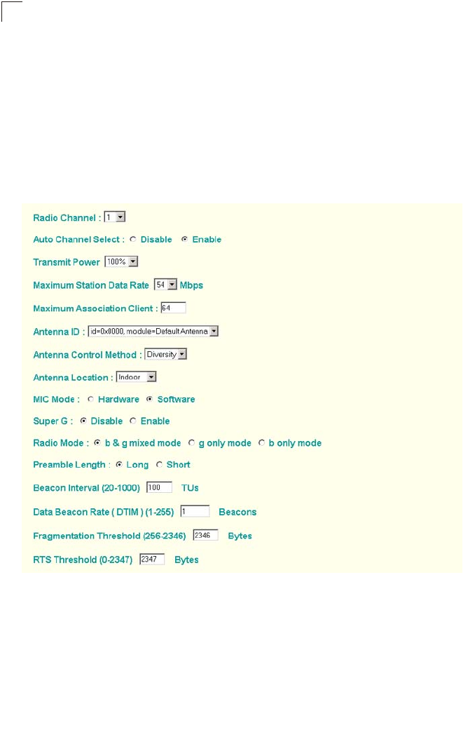
System Configuration
6-64
6
Most of the 802.11g commands are identical to those used by the 802.11a interface.
For information on the these command, refer to the following sections:
• “Configuring VAP Radio Settings” on page 6-49
• “Configuring Rogue AP Detection” on page 6-51
• “Configuring Common Radio Settings” on page 6-54
• “Configuring Wi-Fi Multimedia” on page 6-58
Only the radio settings unique to the 802.11g interface are included in this section.
To configure the 802.11g radio settings, select the Radio Settings page.
Radio Mode – Selects the operating mode for the 802.11g wireless interface.
(Default: 802.11b+g)
• 802.11b+g: Both 802.11b and 802.11g clients can communicate with the access
point (up to 54 Mbps).
• 802.11b only: Both 802.11b and 802.11g clients can communicate with the access
point, but 802.11g clients can only transfer data at 802.11b standard rates (up to
11 Mbps).
• 802.11g only: Only 802.11g clients can communicate with the access point (up to
54 Mbps).

Radio Interface
6-65
6
Radio Channel – The radio channel that the access point uses to communicate with
wireless clients. When multiple access points are deployed in the same area, set the
channel on neighboring access points at least five channels apart to avoid
interference with each other. For example, in the United States you can deploy up to
three access points in the same area (e.g., channels 1, 6, 11). Also note that the
channel for wireless clients is automatically set to the same as that used by the
access point to which it is linked. (Range: 1-11; Default: 1)
Auto Channel Select – Enables the access point to automatically select an
unoccupied radio channel. (Default: Enabled)
Maximum Station Data Rate – The maximum data rate at which the access
point transmits unicast packets on the wireless interface. The maximum
transmission distance is affected by the data rate. The lower the data rate,
the longer the transmission distance. (Default: 54 Mbps)
Super G – The Atheros proprietary Super G performance enhancements
are supported by the access point. These enhancements include bursting,
compression, fast frames and dynamic turbo. Maximum throughput ranges
between 40 to 60 Mbps for connections to Atheros-compatible clients.
(Default: Disabled)
Preamble – Sets the length of the signal preamble that is used at the start of
a data transmission. (Default: Long)
• Long: Sets the preamble to long (192 microseconds). Using a long preamble
ensures the access point can support all 802.11b and 802.11g clients.
• Short or Long: Sets the preamble according to the capability of clients that are
currently asscociated. Uses a short preamble (96 microseconds) if all associated
clients can support it, otherwise a long preamble is used. The access point can
increase data throughput when using a short preamble, but will only use a short
preamble if it determines that all associated clients support it.

System Configuration
6-66
6
CLI Commands for the 802.11g Wireless Interface – From the global configuration
mode, enter the interface wireless g command to access the 802.11g radio
interface. The 802.11g radio can be forced to an 802.11g-only, 802.11b-only, or
mixed 802.11b/g operating mode using the radio-mode command. You should set
the desired operating mode before configuring channel settings (the default is mixed
802.11b/g operation). Select a radio channel or set selection to Auto using the
channel command. Set any other radio settings as required before enabling the
VAP interface (with the no shutdown command). To view the current 802.11g radio
settings for the VAP interface, use the show interface wireless g [0~3] command
as shown on 7-94.
Security
The access point is configured by default as an “open system,” which broadcasts a
beacon signal including the configured SSID. Wireless clients with an SSID setting
of “any” can read the SSID from the beacon and automatically set their SSID to
allow immediate connection to the nearest access point.
To improve wireless network security, you have to implement two main functions:
• Authentication: It must be verified that clients attempting to connect to the network
are authorized users.
• Traffic Encryption: Data passing between the access point and clients must be
protected from interception and eavesdropping.
For a more secure network, the access point can implement one or a combination of
the following security mechanisms:
• Wired Equivalent Privacy (WEP) page 6-67
• IEEE 802.1X page 5-15
• Wireless MAC address filtering page 6-13
• Wi-Fi Protected Access (WPA or WPA2) page 6-75
Both WEP and WPA security settings are configurable separately for each virtual
access point (VAP) interface. MAC address filtering, IEEE 802.1X, and RADIUS
server settings are global and apply to all VAP interfaces.
The security mechanisms that may be employed depend on the level of security
required, the network and management resources available, and the software
support provided on wireless clients.
Enterprise AP(config)#interface wireless g 7-87
Enter Wireless configuration commands, one per line.
Enterprise AP(if-wireless g)#radio-mode g 7-98
Enterprise AP(if-wireless g)#channel auto 7-96
Enterprise AP(if-wireless a)#transmit-power full 7-97
Enterprise AP(if-wireless a)#super-g 7-104
Enterprise AP(if-wireless g)#preamble short 7-98
Enterprise AP(if-wireless g)#

Radio Interface
6-67
6
A summary of wireless security considerations is listed in the following table.
Note: You must enable data encryption through the web or CLI in order to enable all
types of encryption (WEP, TKIP, or AES) in the access point.
Table 6-2. Wireless Security Considerations
Security
Mechanism Client Support Implementation Considerations
WEP Built-in support on all 802.11a
and 802.11g devices • Provides only weak security
• Requires manual key management
WEP over 802.1X Requires 802.1X client support
in system or by add-in software
(support provided in Windows
2000 SP3 or later and Windows
XP)
• Provides dynamic key rotation for improved WEP
security
• Requires configured RADIUS server
• 802.1X EAP type may require management of
digital certificates for clients and server
MAC Address
Filtering Uses the MAC address of client
network card • Provides only weak user authentication
• Management of authorized MAC addresses
• Can be combined with other methods for improved
security
• Optionally configured RADIUS server
WPA over 802.1X
Mode Requires WPA-enabled system
and network card driver
(native support provided in
Windows XP)
• Provides robust security in WPA-only mode
(i.e., WPA clients only)
• Offers support for legacy WEP clients, but with
increased security risk (i.e., WEP authentication
keys disabled)
• Requires configured RADIUS server
• 802.1X EAP type may require management of
digital certificates for clients and server
WPA PSK Mode Requires WPA-enabled system
and network card driver
(native support provided in
Windows XP)
• Provides good security in small networks
• Requires manual management of pre-shared key
WPA2 with 802.1X Requires WPA-enabled system
and network card driver (native
support provided in Windows
XP)
• Provides the strongest security in WPA2-only
mode
• Provides robust security in mixed mode for WPA
and WPA2 clients
• Offers fast roaming for time-sensitive client
applications
• Requires configured RADIUS server
• 802.1X EAP type may require management of
digital certificates for clients and server
• Clients may require hardware upgrade to be WPA2
compliant
WPA2 PSK Mode Requires WPA-enabled system
and network card driver (native
support provided in Windows
XP)
• Provides robust security in small networks
• Requires manual management of pre-shared key
• Clients may require hardware upgrade to be WPA2
compliant

System Configuration
6-68
6
The access point can simultaneously support clients using various different security
mechanisms. The configuration for these security combinations are outlined in the
following table. Note that MAC address authentication can be configured
independently to work with all security mechanisms and is indicated separately in
the table. Required RADIUS server support is also listed.
Table 6-3. Security Combinations
Client Security
Combination Configuration SummaryaMAC
Auth.bRADIUS
Server
Static WEP only (with
or without shared key
authentication)
802.1X: Disable
Enter 1 to 4 WEP keys
Select a WEP transmit key
VAP interface settings:
Authentication Type: Shared Key or Open System
Data Encryption: Enable
WPA Clients: WEP only
Local or
RADIUS Yesc
Dynamic WEP
(802.1X) only 802.1X: Required
Set 802.1X key refresh rates
VAP interface settings:
Authentication Type: Open System
Data Encryption: Enable
WPA Clients: WEP only
Local or
RADIUS Yesc
802.1X WPA only 802.1X: Required
Set 802.1X key refresh rates
VAP interface settings:
Authentication Type: Open System
Data Encryption: Enable
WPA Clients: Required
WPA Key Mode: WPA over 802.1X
WPA Multicast Cipher: TKIP or AES
Local only Yes
WPA Pre-Shared Key
only 802.1X: Disable
VAP interface settings:
Authentication Type: Open System
Data Encryption: Enable
WPA Clients: Required
WPA Key Mode: WPA Pre-shared Key
Enter a WPA Pre-shared key
WPA Multicast Cipher: TKIP or AES
Local only No
Static and dynamic
(802.1X) WEP keys 802.1X: Supported
Set 802.1X key refresh rates
Enter 1 to 4 WEP keys
Select a WEP transmit key
VAP interface settings:
Authentication Type: Open System
Data Encryption: Enable
WPA clients: WEP only
Local or
RADIUS Yes

Radio Interface
6-69
6
Note: If you choose to configure RADIUS MAC authentication together with 802.1X, the
RADIUS MAC address authentication occurs prior to 802.1X authentication. Only
when RADIUS MAC authentication succeeds is 802.1X authentication performed.
When RADIUS MAC authentication fails, 802.1X authentication is not performed.
Static WEP and WPA
Pre-Shared Key 802.1X: Disable
Enter 1 to 4 WEP keys
Select a WEP transmit key
VAP interface settings:
Authentication Type: Open System
Data Encryption: Enable
WPA Clients: Supported
WPA Key Mode: WPA Pre-shared Key
Enter a WPA Pre-shared key
WPA Multicast Cipher: WEP
Local only No
Dynamic WEP and
802.1X WPA 802.1X: Required
Set 802.1X key refresh rates
VAP interface settings:
Authentication Type: Open System
Data Encryption: Enable
WPA Clients: Supported
WPA Key Mode: WPA over 802.1X
WPA Multicast Cipher: WEP
Local only Yes
Static and dynamic
(802.1X) WEP keys
and 802.1X WPA
802.1X: Supported
Set 802.1X key refresh rates
Enter 1 to 4 WEP keys
Select a WEP transmit key
VAP interface settings:
Authentication Type: Open System
Data Encryption: Enable
WPA Clients: Supported
WPA Key Mode: WPA over 802.1X
WPA Multicast Cipher: WEP
Local only Yes
a. The configuration summary does not include the setup for MAC authentication (see page 6-12) or
RADIUS server (see page 6-7).
b. The configuration of RADIUS MAC authentication together with 802.1X WPA or WPA Pre-shared
Key is not supported.
c. RADIUS server required only when RADIUS MAC authentication is configured.
Table 6-3. Security Combinations
Client Security
Combination Configuration SummaryaMAC
Auth.bRADIUS
Server
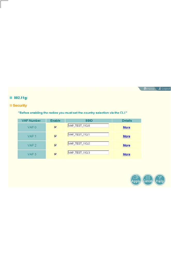
System Configuration
6-70
6
Enabling the VAPs
Before enabling the Virtual Access Point (VAP) radio interfaces, first configure all of
the relevant raido settings (see “Radio Settings A (802.11a)” on page 6-49 or “Radio
Settings G (802.11g)” on page 6-63.)
After you have configured the radio settnings, select Security under Radio A or
Radio G, set an SSID to identify the wireless network service provided by each VAP
you want to use, and then click Apply to save your settings.
Before enabling the radio service for any VAP, first configure the WEP, WPA, and
802.1X security settings described in the following sections. After you have finished
configuring the security settings, return to the main Security page shown below, start
the required VAP interfaces by clicking the Enable checkbox, and then click Apply.
Enable – Enables radio communications on the VAP interface. (Default: Disabled)
Note:
You must first enable VAP interface 0 before you can enable other VAP interfaces.
SSID – The name of the basic service set provided by a VAP interface. Clients that
want to connect to the network through the access point must set their SSID to the
same as that of an access point VAP interface. (Default: SMC_A # (0 to 3); Range:
1-32 characters)
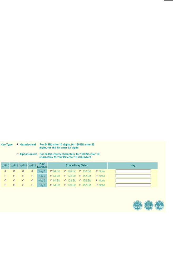
Radio Interface
6-71
6
Wired Equivalent Privacy (WEP)
WEP provides a basic level of security, preventing unauthorized access to the
network, and encrypting data transmitted between wireless clients and the access
point. WEP uses static shared keys (fixed-length hexadecimal or alphanumeric
strings) that are manually distributed to all clients that want to use the network.
WEP is the security protocol initially specified in the IEEE 802.11 standard for
wireless communications. Unfortunately, WEP has been found to be seriously
flawed and cannot be recommended for a high level of network security. For more
robust wireless security, the access point provides Wi-Fi Protected Access (WPA)
for improved data encryption and user authentication.
Setting up shared keys enables the basic IEEE 802.11 Wired Equivalent Privacy
(WEP) on the access point to prevent unauthorized access to the network.
If you choose to use WEP shared keys instead of an open system, be sure to define
at least one static WEP key for user authentication and data encryption. Also, be
sure that the WEP shared keys are the same for each client in the wireless network.
Note that all clients share the same keys, which are used for user authentication and
data encryption. Up to four keys can be specified. These four keys are used for all
VAP interfaces on the same radio.
To set up WEP shared keys, click Radio Settings under Radio A or Radio G.
Key Type – Select the preferred method of entering WEP encryption keys on the
access point and enter up to four keys:
• Hexadecimal: Enter keys as 10 hexadecimal digits (0-9 and A-F) for 64 bit keys,
26 hexadecimal digits for 128 bit keys, or 32 hexadecimal digits for 152 bit keys
(802.11a radio only). This is the default setting.
• Alphanumeric: Enter keys as 5 alphanumeric characters for 64 bit keys, 13
alphanumeric characters for 128 bit keys, or 16 alphanumeric characters for 152
bit keys (802.11a radio only).
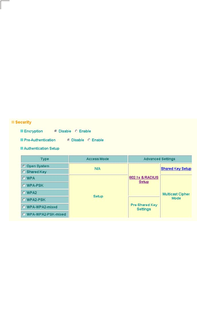
System Configuration
6-72
6
Key Number – Selects the key number to use for encryption for each VAP interface.
If the clients have all four keys configured to the same values, you can change the
encryption key to any of the four settings without having to update the client keys.
(Default: Key 1)
Shared Key Setup – Select 64 Bit, 128 Bit, or 152 Bit key length. Note that the same
size of encryption key must be supported on all wireless clients. (Default: None)
Note: Key index and type must match that configured on the clients.
Note: In a mixed-mode environment with clients using static WEP keys and WPA, select
WEP transmit key index 2, 3, or 4. The access point uses transmit key index 1 for
the generation of dynamic keys.
To enable WEP shared keys for a VAP interface, click Security under Radio A or
Radio G. Then, select the VAP interface that will use WEP keys by clicking More,
and configure the Authentication Type Setup and Data Encryption fields.
Authentication Type Setup – Sets the access point to communicate as an open
system that accepts network access attempts from any client, or with clients using
pre-configured static shared keys. (Default: Open System)
• Open System: Select this option if you plan to use WPA or 802.1X as a security
mechanism. If you don’t set up any other security mechanism on the access point,
the network has no protection and is open to all users. This is the default setting.
• Shared Key: Sets the access point to use WEP shared keys. If this option is
selected, you must configure at least one key on the access point and all clients.
Note: To use 802.1X on wireless clients requires a network card driver and 802.1X
client software that supports the EAP authentication type that you want to use.
Windows 2000 SP3 or later and Windows XP provide 802.1X client support.
Windows XP also provides native WPA support. Other systems require additional
client software to support 802.1X and WPA.

Radio Interface
6-73
6
Data Encryption – Enable or disable the access point to use data encryption (WEP,
TKIP, or AES). If this option is selected when using static WEP keys, you must
configure at
least one key on the access point and all clients. (Default: Disabled)
Note: You must enable data encryption through the web or CLI in order to enable all
types of encryption (WEP, TKIP, or AES) in the access point.
CLI Commands for WEP Shared Key Security – For static WEP shared keys, be
sure to first disable 802.1X port authentication using the 802.1X command from the
configuration mode. Then, from the 802.11a or 802.11g interface configuration
mode, use the key command to define up to four WEP keys that can be used for all
VAP interfaces on the radio. Then use the vap command to access each VAP
interface to configure other security settings.
From the VAP interface configuration mode, use the authentication command to
enable WEP shared-key authentication and the encryption command to enable
data encryption. Then set one key as the transmit key for the VAP interface using
the transmit-key command. To view the current security settings, use the show
interface wireless a 0 or show interface wireless g 0 command from the Exec
mode.
Enterprise AP(config)#no 802.1X 7-65
Enterprise AP(config)#interface wireless g 7-87
Enter Wireless configuration commands, one per line.
Enterprise AP(if-wireless g)#key 1 128 ascii abcdeabcdeabc 7-119
Enterprise AP(if-wireless g)#vap 0 7-94
Enterprise AP(if-wireless g: VAP[0])#authentication shared 7-119
Enterprise AP(if-wireless g: VAP[0])#encryption 7-118
Enterprise AP(if-wireless g: VAP[0])#transmit-key 1 7-120
Enterprise AP(if-wireless g: VAP[0])#exit
Enterprise AP#show interface wireless g 0 7-109
Wireless Interface Information
========================================================================
----------------Identification------------------------------------------
Description : SMC 802.11g Access Point
SSID : SMC_G 0
Channel : 11 (AUTO)
Status : DISABLED
MAC Address : 00:12:cf:05:95:08
----------------802.11 Parameters----------------------------------------
Radio Mode : b & g mixed mode
Transmit Power : FULL (5 dBm)
Max Station Data Rate : 54Mbps
Multicast Data Rate : 5.5Mbps
Fragmentation Threshold : 2346 bytes
RTS Threshold : 2347 bytes
Beacon Interval : 100 TUs
Authentication Timeout Interval : 60 Mins
Association Timeout Interval : 30 Mins
DTIM Interval : 1 beacon
Preamble Length : SHORT-OR-LONG
Maximum Association : 64 stations
MIC Mode : Software
Super G : Disabled
VLAN ID : 1

System Configuration
6-74
6
----------------Security------------------------------------------------
Closed System : Disabled
Multicast cipher : WEP
Unicast cipher : TKIP and AES
WPA clients : DISABLED
WPA Key Mgmt Mode : PRE SHARED KEY
WPA PSK Key Type : PASSPHRASE
WPA PSK Key : EMPTY
PMKSA Lifetime : 720 minutes
Encryption : DISABLED
Default Transmit Key : 1
Common Static Keys : Key 1: EMPTY Key 2: EMPTY
Key 3: EMPTY Key 4: EMPTY
Pre-Authentication : DISABLED
Authentication Type : OPEN
----------------802.1x--------------------------------------------------
802.1x : DISABLED
Broadcast Key Refresh Rate : 30 min
Session Key Refresh Rate : 30 min
802.1x Session Timeout Value : 0 min
----------------Antenna-------------------------------------------------
Antenna Control method : Diversity
Antenna ID : 0x0000(Default Antenna)
Antenna Location : Indoor
----------------Quality of Service---------------------------------------
WMM Mode : SUPPORTED
WMM Acknowledge Policy
AC0(Best Effort) : Acknowledge
AC1(Background) : Acknowledge
AC2(Video) : Acknowledge
AC3(Voice) : Acknowledge
WMM BSS Parameters
AC0(Best Effort) : logCwMin: 4 logCwMax: 10 AIFSN: 3
Admission Control: No
TXOP Limit: 0.000 ms
AC1(Background) : logCwMin: 4 logCwMax: 10 AIFSN: 7
Admission Control: No
TXOP Limit: 0.000 ms
AC2(Video) : logCwMin: 3 logCwMax: 4 AIFSN: 2
Admission Control: No
TXOP Limit: 3.008 ms
AC3(Voice) : logCwMin: 2 logCwMax: 3 AIFSN: 2
Admission Control: No
TXOP Limit: 1.504 ms
WMM AP Parameters
AC0(Best Effort) : logCwMin: 4 logCwMax: 6 AIFSN: 3
Admission Control: No
TXOP Limit: 0.000 ms
AC1(Background) : logCwMin: 4 logCwMax: 10 AIFSN: 7
Admission Control: No
TXOP Limit: 0.000 ms
AC2(Video) : logCwMin: 3 logCwMax: 4 AIFSN: 1
Admission Control: No
TXOP Limit: 3.008 ms
AC3(Voice) : logCwMin: 2 logCwMax: 3 AIFSN: 1
Admission Control: No
TXOP Limit: 1.504 ms
========================================================================
Enterprise AP#

Radio Interface
6-75
6
CLI Commands for WEP over 802.1X Security – First set 802.1X to required using
the 802.1X command and set the 802.1X key refresh rates. Then, from the 802.11a
or 802.11g interface configuration mode, use the vap command to access each VAP
interface to configure other security settings. From the VAP interface configuration
mode, use the authentication command to select open system authentication and
the encryption command to enable data encryption. Be sure that WPA is disabled
by using the wpa-clients wep-only command. To view the current security settings,
use the show interface wireless a 0 or show interface wireless g 0 command
(not shown in example).
Wi-Fi Protected Access (WPA)
WPA employs a combination of several technologies to provide an enhanced
security solution for 802.11 wireless networks.
The access point supports the following WPA components and features:
IEEE 802.1X and the Extensible Authentication Protocol
(EAP):
WPA employs
802.1X as its basic framework for user authentication and dynamic key
management. The 802.1X client and RADIUS server should use an appropriate EAP
type—such as EAP-TLS (Transport Layer Security), EAP-TTLS (Tunneled TLS), or
PEAP (Protected EAP)—for strongest authentication. Working together, these
protocols provide “mutual authentication” between a client, the access point, and a
RADIUS server that prevents users from accidentally joining a rogue network. Only
when a RADIUS server has authenticated a user’s credentials will encryption keys
be sent to the access point and client.
Note: To implement WPA on wireless clients requires a WPA-enabled network card
driver and 802.1X client software that supports the EAP authentication type that
you want to use. Windows XP provides native WPA support, other systems
require additional software.
Temporal Key Integrity Protocol (TKIP): WPA specifies TKIP as the data
encryption method to replace WEP. TKIP avoids the problems of WEP static keys by
dynamically changing data encryption keys. Basically, TKIP starts with a master
(temporal) key for each user session and then mathematically generates other keys
Enterprise AP(if-wireless g)#vap 0
Enterprise AP(if-wireless g: VAP[0])#802.1X required 7-65
Enterprise AP(if-wireless g: VAP[0])#802.1X
broadcast-key-refresh-rate 5 7-66
Enterprise AP(if-wireless g: VAP[0])#802.1X
session-key-refresh-rate 5 7-67
Enterprise AP(if-wireless g: VAP[0])#802.1X session-timeout 300 7-67
Enterprise AP(if-wireless g: VAP[0])#interface wireless g 7-87
Enter Wireless configuration commands, one per line.
Enterprise AP(if-wireless g: VAP[0])#authentication open 7-119
Enterprise AP(if-wireless g: VAP[0])#encryption 7-118
Enterprise AP(if-wireless g: VAP[0])#

System Configuration
6-76
6
to encrypt each data packet. TKIP provides further data encryption enhancements
by including a message integrity check for each packet and a re-keying mechanism,
which periodically changes the master key.
WPA Pre-Shared Key Mode (WPA-PSK, WPA2-PSK): For enterprise deployment,
WPA requires a RADIUS authentication server to be configured on the wired
network. However, for small office networks that may not have the resources to
configure and maintain a RADIUS server, WPA provides a simple operating mode
that uses just a pre-shared password for network access. The Pre-Shared Key
mode uses a common password for user authentication that is manually entered on
the access point and all wireless clients. The PSK mode uses the same TKIP packet
encryption and key management as WPA in the enterprise, providing a robust and
manageable alternative for small networks.
Mixed WPA and WEP Client Support: WPA enables the access point to indicate its
supported encryption and authentication mechanisms to clients using its beacon
signal. WPA-compatible clients can likewise respond to indicate their WPA support.
This enables the access point to determine which clients are using WPA security
and which are using legacy WEP. The access point uses TKIP unicast data
encryption keys for WPA clients and WEP unicast keys for WEP clients. The global
encryption key for multicast and broadcast traffic must be the same for all clients,
therefore it restricts encryption to a WEP key.
When access is opened to both WPA and WEP clients, no authentication is provided
for the WEP clients through shared keys. To support authentication for WEP clients
in this mixed mode configuration, you can use either MAC authentication or 802.1X
authentication.
WPA2 – WPA was introduced as an interim solution for the vulnerability of WEP
pending the ratification of the IEEE 802.11i wireless security standard. In effect, the
WPA security features are a subset of the 802.11i standard. WPA2 includes the now
ratified 802.11i standard, but also offers backward compatibility with WPA.
Therefore, WPA2 includes the same 802.1X and PSK modes of operation and
support for TKIP encryption. The main differences and enhancements in WPA2 can
be summarized as follows:
•Advanced Encryption Standard (AES): WPA2 uses AES Counter-Mode
encryption with Cipher Block Chaining Message Authentication Code (CBC-MAC)
for message integrity. The AES Counter-Mode/CBCMAC Protocol (AES-CCMP)
provides extremely robust data confidentiality using a 128-bit key. The AES-CCMP
encryption cipher is specified as a standard requirement for WPA2. However, the
computational intensive operations of AES-CCMP requires hardware support on
client devices. Therefore to implement WPA2 in the network, wireless clients must
be upgraded to WPA2-compliant hardware.
•WPA2 Mixed-Mode: WPA2 defines a transitional mode of operation for networks
moving from WPA security to WPA2. WPA2 Mixed Mode allows both WPA and
WPA2 clients to associate to a common SSID interface. In mixed mode, the unicast
encryption cipher (TKIP or AES-CCMP) is negotiated for each client. The access
point advertises its supported encryption ciphers in beacon frames and probe

Radio Interface
6-77
6
responses. WPA and WPA2 clients select the cipher they support and return the
choice in the association request to the access point. For mixed-mode operation,
the cipher used for broadcast frames is always TKIP. WEP encryption is not
allowed.
•Key Caching: WPA2 provides fast roaming for authenticated clients by retaining
keys and other security information in a cache, so that if a client roams away from
an access point and then returns, re-authentication is not required. When a WPA2
client is first authenticated, it receives a Pairwise Master Key (PMK) that is used to
generate other keys for unicast data encryption. This key and other client
information form a Security Association that the access point names and holds in
a cache.
•Preauthentication: Each time a client roams to another access point it has to be
fully re-authenticated. This authentication process is time consuming and can
disrupt applications running over the network. WPA2 includes a mechanism,
known as pre-authentication, that allows clients to roam to a new access point and
be quickly associated. The first time a client is authenticated to a wireless network
it has to be fully authenticated. When the client is about to roam to another access
point in the network, the access point sends pre-authentication messages to the
new access point that include the client’s security association information. Then
when the client sends an association request to the new access point, the client is
known to be already authenticated, so it proceeds directly to key exchange and
association.
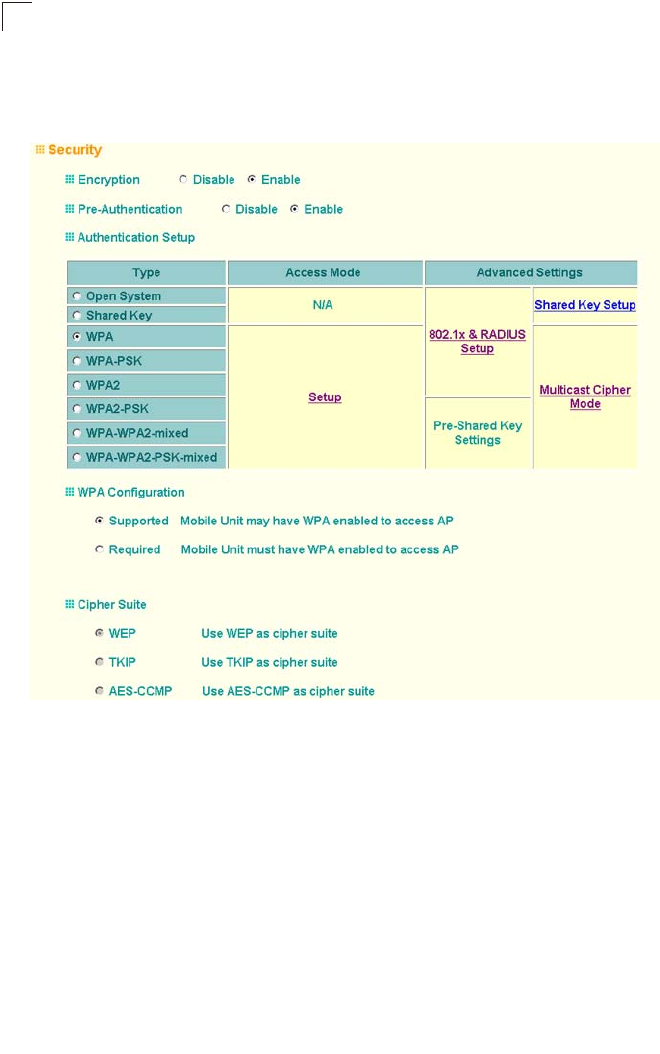
System Configuration
6-78
6
To configure WPA, click Security under Radio A or Radio G. Select one of the VAP
interfaces by clicking More. Select one of the WPA options in the Authentication
Setup table, and then configure the parameters displayed beneath the table.
The WPA configuration parameters are described below:
Data Encryption Mode – You must enable data encryption in order to enable all
types of encryption (WEP, TKIP, or AES) in the access point.
Pre-Authentication – When using WPA2 over 802.1X, pre-authentication can be
enabled, which allows clients to roam to a new access point and be quickly
associated without performing full 802.1X authentication. (Default: Disabled)
Authentication Setup – To use WPA or WPA2, set the access point to one of the
following options. If a WPA/WPA2 mode that operates over 802.1X is selected
(WPA, WPA2, WPA-WPA2-mixed, or WPA-WPA2-PSK-mixed), the 802.1X settings
and RADIUS server details need to be configured. Be sure you have also configured
a RADIUS server on the network before enabling authentication. If a WPA/WPA2
Pre-shared Key mode is selected (WPA-PSK or WPA2-PSK), be sure to specify the
key string.

Radio Interface
6-79
6
• WPA: Clients using WPA over 802.1X are accepted for authentication.
• WPA-PSK: Clients using WPA with a Pre-shared Key are accepted for
authentication.
• WPA2: Clients using WPA2 over 802.1X are accepted for authentication.
• WPA2-PSK: Clients using WPA2 with a Pre-shared Key are accepted for
authentication.
• WPA-WPA2-mixed: Clients using WPA or WPA2 over 802.1X are accepted for
authentication.
• WPA-WPA2-PSK-mixed: Clients using WPA or WPA2 with a Pre-shared Key are
accepted for authentication.
WPA Configuration – Each VAP interface can be configured to allow only
WPA-enabled clients to access the network (Required), or to allow access to both
WPA and WEP clients (Supported). (Default: Required)
Cipher Suite – Selects an encryption method for the global key used for multicast
and broadcast traffic, which is supported by all wireless clients.
• WEP: WEP is used as the multicast encryption cipher. You should select WEP only
when both WPA and WEP clients are supported.
• TKIP: TKIP is used as the multicast encryption cipher.
• AES-CCMP: AES-CCMP is used as the multicast encryption cipher. AES-CCMP
is the standard encryption cipher required for WPA2.
WPA Pre-Shared Key Type – If the WPA or WPA2 pre-shared-key mode is used, all
wireless clients must be configured with the same key to communicate with the
access point.
•Hexadecimal – Enter a key as a string of 64 hexadecimal numbers.
•Alphanumeric – Enter a key as an easy-to-remember form of letters and numbers.
The string must be from 8 to 63 characters, which can include spaces.

System Configuration
6-80
6
The configuration settings for WPA are summarized below:
CLI Commands for WPA Using Pre-shared Key Security – Be sure to first disable
802.1X port authentication using the 802.1X command from the configuration mode.
Then, from the 802.11a or 802.11g interface configuration mode, use the vap
command to access each VAP interface to configure other security settings.
From the VAP interface configuration mode, use the authentication command to
set the access point to “Open System.” Use the encryption command to enable
data encryption. To enable WPA to be required for all clients, use the wpa-clients
command. Set the broadcast and multicast key encryption using the
multicast-cipher command. Use the wpa-mode command to enable the
Pre-shared Key mode. To enter a key value, use the wpa-psk-type command to
specify a hexadecimal or alphanumeric key, and then use the wpa-preshared-key
command to define the key. To view the current security settings, use the show
interface wireless a 0 or show interface wireless g 0 command (not shown in
example).
Table 6-4. WPA Configuration Settings
WPA and WPA2 pre-shared key only WPA and WPA2 over 802.1X
Authentication Type: Open System
Data Encryption: Enabled
Key Source: Authentication Server
Authentication Setup: WPA-PSK or WPA2-PSK
WPA Key Management: WPA/WPA2 pre-shared key
WPA Cipher Mode: WEP/TKIP/AES-CCMP
WPA Pre-shared Key Type: Hex/ASCII
Authentication Type: Open System
Data encryption: Enabled
Key Source: Authentication Server
Authentication Setup: WPA, WPA2,
WPA-WPA2-mixed, or WPA-WPA2-PSK-mixed
WPA Key Management: WPA/WPA2 over 802.1x
WPA Cipher Mode: WEP/TKIP/AES-CCMP
Key Type: Hex/ASCII
Shared Key: 64/128/152 bits
Transmit Key: 1/2/3/4
(requires RADIUS server to be specified)
1: You must enable data encryption in order to enable all types of encryption in the access point.
2: Select Auto or TKIP when any WPA clients do not support AES. Select AES only if all clients support AES.
Enterprise AP(config)#interface wireless g 7-87
Enter Wireless configuration commands, one per line.
Enterprise AP(if-wireless g)#vap 0
Enterprise AP(if-wireless g: VAP[0])#no 802.1X 7-65
Enterprise AP(if-wireless g: VAP[0])#authentication open 7-119
Enterprise AP(if-wireless g: VAP[0])#encryption 7-118
Enterprise AP(if-wireless g: VAP[0])#wpa-clients required 7-123
Enterprise AP(if-wireless g: VAP[0])#multicast-cipher TKIP 7-121
Enterprise AP(if-wireless g: VAP[0])#wpa-preshared-key
ASCII agoodsecret 7-123
Enterprise AP(if-wireless g: VAP[0])#

Radio Interface
6-81
6
CLI Commands for WPA Over 802.1X Security – First set 802.1X to required using
the 802.1X command and set the 802.1X key refresh rates. Then, from the 802.11a
or 802.11g interface configuration mode, use the vap command to access each VAP
interface to configure other security settings.
From the VAP interface configuration mode, use the authentication command to
select open system authentication and the encryption command to enable data
encryption. Use the wpa-clients command to set WPA to be required or supported
for clients. Use the wpa-mode command to enable WPA dynamic keys over 802.1X.
Set the broadcast and multicast key encryption using the multicast-cipher
command. To view the current security settings, use the show interface wireless a
0 or show interface wireless g 0 command (not shown in example).
Configuring 802.1X
IEEE 802.1X is a standard framework for network access control that uses a central
RADIUS server for user authentication. This control feature prevents unauthorized
access to the network by requiring an 802.1X client application to submit user
credentials for authentication. The 802.1X standard uses the Extensible
Authentication Protocol (EAP) to pass user credentials (either digital certificates,
user names and passwords, or other) from the client to the RADIUS server. Client
authentication is then verified on the RADIUS server before the access point grants
client access to the network.
The 802.1X EAP packets are also used to pass dynamic unicast session keys and
static broadcast keys to wireless clients. Session keys are unique to each client and
are used to encrypt and correlate traffic passing between a specific client and the
access point. You can also enable broadcast key rotation, so the access point
provides a dynamic broadcast key and changes it at a specified interval.
Enterprise AP(config)#interface wireless g 7-87
Enter Wireless configuration commands, one per line.
Enterprise AP(if-wireless g)#vap 0
Enterprise AP(if-wireless g: VAP[0])#802.required 7-65
Enterprise AP(if-wireless g: VAP[0])#802.1X
broadcast-key-refresh-rate 5 7-66
Enterprise AP(if-wireless g: VAP[0])#802.1X
session-key-refresh-rate 5 7-67
Enterprise AP(if-wireless g: VAP[0])#802.1X session-timeout 300 7-67
Enterprise AP(if-wireless g: VAP[0])#authentication open 7-119
Enterprise AP(if-wireless g: VAP[0])#encryption 7-118
Enterprise AP(if-wireless g: VAP[0])#wpa-clients required 7-123
Enterprise AP(if-wireless g: VAP[0])#multicast-cipher TKIP 7-121
Enterprise AP(if-wireless g: VAP[0])#

System Configuration
6-82
6
Open the Security page, and click More for one of the VAP interfaces.
You can enable 802.1X as optionally supported or as required to enhance the
security of the wireless network. (Default: Disable)
• Disable: The access point does not support 802.1X authentication for any wireless
client. After successful wireless association with the access point, each client is
allowed to access the network.
• Supported: The access point supports 802.1X authentication only for clients
initiating the 802.1X authentication process (i.e., the access point does not initiate
802.1X authentication). For clients initiating 802.1X, only those successfully
authenticated are allowed to access the network. For those clients not initiating
802.1X, access to the network is allowed after successful wireless association
with the access point. The 802.1X supported mode allows access for clients not
using WPA or WPA2 security.
• Required: The access point enforces 802.1X authentication for all associated
wireless clients. If 802.1X authentication is not initiated by a client, the access
point will initiate authentication. Only those clients successfully authenticated with
802.1X are allowed to access the network.
Note: If 802.1X is enabled on the access point, then RADIUS setup must be completed
(see “RADIUS” on page 6-7).
When 802.1X is enabled, the broadcast and session key rotation intervals can also
be configured.
• Broadcast Key Refresh Rate: Sets the interval at which the broadcast keys are
refreshed for stations using 802.1X dynamic keying. (Range: 0-1440 minutes;
Default: 0 means disabled)
• Session Key Refresh Rate: The interval at which the access point refreshes
unicast session keys for associated clients. (Range: 0-1440 minutes; Default: 0
means disabled)

Radio Interface
6-83
6
• 802.1X Reauthentication Refresh Rate: The time period after which a connected
client must be re-authenticated. During the re-authentication process of verifying
the client’s credentials on the RADIUS server, the client remains connected the
network. Only if re-authentication fails is network access blocked. (Range:
0-65535 seconds; Default: 0 means disabled)
CLI Commands for 802.1X Authentication – Use the 802.1X supported command
from the VAP interface mode to enable 802.1X authentication. Set the session and
broadcast key refresh rate, and the re-authentication timeout. To display the current
settings, use the show authentication command from the Exec mode.
Enterprise AP(if-wireless g: VAP[0])#802.1X supported 7-65
Enterprise AP(if-wireless g: VAP[0])#802.1X
broadcast-key-refresh-rate 5 7-66
Enterprise AP(if-wireless g: VAP[0])#802.1X
session-key-refresh-rate 5 7-67
Enterprise AP(if-wireless g: VAP[0])#802.1X
session-timeout 300 7-67
Enterprise AP(if-wireless g: VAP[0])#exit
Enterprise AP#show authentication 7-68
Authentication Information
===========================================================
MAC Authentication Server : DISABLED
MAC Auth Session Timeout Value : 0 min
802.1x supplicant : DISABLED
802.1x supplicant user : EMPTY
802.1x supplicant password : EMPTY
Address Filtering : ALLOWED
System Default : ALLOW addresses not found in filter table.
Filter Table
MAC Address Status
----------------- ----------
00-70-50-cc-99-1a DENIED
00-70-50-cc-99-1b ALLOWED
=========================================================
Enterprise AP#
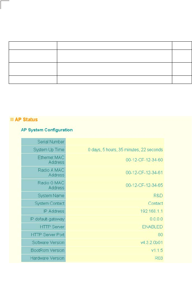
System Configuration
6-84
6
Status Information
The Status page includes information on the following items:
Access Point Status
The AP Status window displays basic system configuration settings, as well as the
settings for the wireless interface.
Menu Description Page
AP Status Displays configuration settings for the basic system and the
wireless interface 6-84
Station Status Shows the wireless clients currently associated with the access
point 6-87
Event Logs Shows log messages stored in memory 6-90
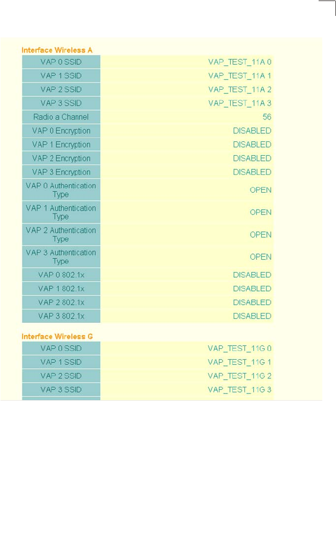
Status Information
6-85
6
AP System Configuration – The AP System Configuration table displays the basic
system configuration settings:
• System Up Time: Length of time the management agent has been up.
• MAC Address: The physical layer address for this device.
• System Name: Name assigned to this system.
• System Contact: Administrator responsible for the system.
• IP Address: IP address of the management interface for this device.
• IP Default Gateway: IP address of the gateway router between this device and
management stations that exist on other network segments.

System Configuration
6-86
6
• HTTP Server: Shows if management access via HTTP is enabled.
• HTTP Server Port: Shows the TCP port used by the HTTP interface.
• Version: Shows the version number for the runtime code.
AP Wireless Configuration – The AP Wireless Configuration tables display the radio
and VAP interface settings listed below. Note that Interface Wireless A refers to the
802.11a radio and Interface Wireless G refers the 802.11b/g radio.
• SSID: The service set identifier for the VAP interface.
• Radio Channel: The radio channel through which the access point communicates
with wireless clients.
• Encryption: The key size used for data encryption.
• Authentication Type: Shows the type of authentication used.
• 802.1X: Shows if IEEE 802.1X access control for wireless clients is enabled.
CLI Commands for Displaying System Settings – To view the current access point
system settings, use the show system command from the Exec mode. To view the
current radio interface settings, use the show interface wireless a 0 or show
interface wireless g 0 command (see page 7-109).
Enterprise AP#show system 7-23
System Information
==========================================================
Serial Number : A123456789
System Up time : 0 days, 4 hours, 33 minutes, 29 seconds
System Name : SMC
System Location :
System Contact :
System Country Code : US - UNITED STATES
MAC Address : 00-30-F1-F0-9A-9C
IP Address : 192.168.1.1
Subnet Mask : 255.255.255.0
Default Gateway : 0.0.0.0
VLAN State : DISABLED
Management VLAN ID(AP): 1
IAPP State : ENABLED
DHCP Client : ENABLED
HTTP Server : ENABLED
HTTP Server Port : 80
HTTPS Server : ENABLED
HTTPS Server Port : 443
Slot Status : Dual band(a/g)
Boot Rom Version : v3.0.7
Software Version : v4.3.2.2
SSH Server : ENABLED
SSH Server Port : 22
Telnet Server : ENABLED
WEB Redirect : DISABLED
DHCP Relay : DISABLED
==========================================================
Enterprise AP#
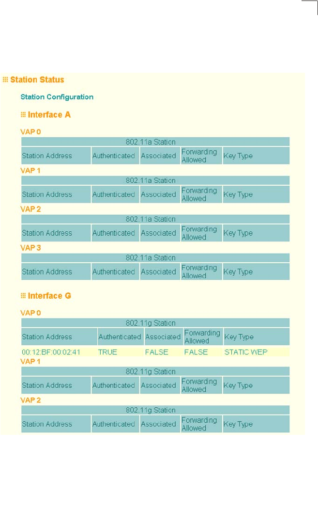
Status Information
6-87
6
Station Status
The Station Status window shows the wireless clients currently associated with the
access point.
The Station Configuration page displays basic connection information for all
associated stations as described below. Note that this page is automatically
refreshed every five seconds.
• Station Address: The MAC address of the wireless client.

System Configuration
6-88
6
• Authenticated: Shows if the station has been authenticated. The two basic
methods of authentication supported for 802.11 wireless networks are “open
system” and “shared key.” Open-system authentication accepts any client
attempting to connect to the access point without verifying its identity. The
shared-key approach uses Wired Equivalent Privacy (WEP) to verify client identity
by distributing a shared key to stations before attempting authentication.
• Associated: Shows if the station has been successfully associated with the access
point. Once authentication is completed, stations can associate with the current
access point, or reassociate with a new access point. The association procedure
allows the wireless system to track the location of each mobile client, and ensure
that frames destined for each client are forwarded to the appropriate access point.
• Forwarding Allowed: Shows if the station has passed 802.1X authentication and
is now allowed to forward traffic to the access point.
• Encryption: The data encryption method used for this client.
• Authentication Type: The authentication method used for this client; including
WEP (Open System or Pre-Shared Key), WPA, WPA2, or some combination.
• SSID: The Service Set Identifier this client used to associate with the VAP.
• Channel: The radio channel this client is using to communicate with the VAP.
• Data Rate: The data rate at which this client is communicating with the VAP.

Status Information
6-89
6
CLI Commands for Displaying Station Status – To view status of clients currently
associated with the access point, use the show station command from the Exec
mode.
Enterprise AP#show station 7-110
Station Table Information
===========================================================
if-wireless A VAP [0] :
802.11a Channel : Auto
No 802.11a Channel Stations.
if-wireless A VAP [1] :
802.11a Channel : Auto
No 802.11a Channel Stations.
if-wireless A VAP [2] :
802.11a Channel : Auto
No 802.11a Channel Stations.
if-wireless A VAP [3] :
802.11a Channel : Auto
No 802.11a Channel Stations.
if-wireless G VAP [0] :
802.11g Channel : Auto
No 802.11g Channel Stations.
if-wireless G VAP [1] :
802.11g Channel : Auto
No 802.11g Channel Stations.
if-wireless G VAP [2] :
802.11g Channel : Auto
No 802.11g Channel Stations.
if-wireless G VAP [3] :
802.11g Channel : Auto
No 802.11g Channel Stations.
===========================================================
Enterprise AP#

System Configuration
6-90
6
Event Logs
The Event Logs window shows the log messages generated by the access point and
stored in memory.
The Event Logs table displays the following information:
• Log Time: The time the log message was generated.
• Event Level: The logging level associated with this message. For a description of
the various levels, see “logging level” on page 6-33.
• Event Message: The content of the log message.
Error Messages – An example of a logged error message is: “Station Failed to
authenticate (unsupported algorithm).”
This message may be caused by any of the following conditions:
• Access point was set to “Open Authentication”, but a client sent an authentication
request frame with a “Shared key.”
• Access point was set to “Shared Key Authentication,” but a client sent an
authentication frame for “Open System.”
• WEP keys do not match: When the access point uses “Shared Key
Authentication,” but the key used by client and access point are not the same, the
frame will be decrypted incorrectly, using the wrong algorithm and sequence
number.

Status Information
6-91
6
CLI Commands for Displaying the Logging Status – From the global configuration
mode, use the show logging command.
CLI Commands for Displaying Event Logs – To view the access point log entries,
use the show event-log command from the Exec mode. To clear all log entries from
the access point, use the logging clear command from the Global Configuration
mode.
Enterprise AP#show loggging 7-32
Logging Information
============================================
Syslog State : Enabled
Logging Console State : Enabled
Logging Level : Alert
Logging Facility Type : 16
Servers
1: 192.168.1.19, UDP Port: 514, State: Enabled
2: 0.0.0.0, UDP Port: 514, State: Disabled
3: 0.0.0.0, UDP Port: 514, State: Disabled
4: 0.0.0.0, UDP Port: 514, State: Disabled
=============================================
Enterprise AP#
Enterprise AP#show event-log 7-33
Mar 09 11:57:55 Information: 802.11g:11g Radio Interface Enabled
Mar 09 11:57:55 Information: 802.11g:Radio channel updated to 8
Mar 09 11:57:34 Information: 802.11g:11g Radio Interface Enabled
Mar 09 11:57:18 Information: 802.11g:11g Radio Interface Enabled
Mar 09 11:56:35 Information: 802.11a:11a Radio Interface Enabled
Mar 09 11:55:52 Information: SSH task: Set SSH server port to 22
Mar 09 11:55:52 Information: SSH task: Enable SSH server.
Mar 09 11:55:52 Information: Enable Telnet.
Mar 09 11:55:40 Information: 802.11a:11a Radio Interface Disabled
Mar 09 11:55:40 Information: 802.11a:Transmit Power set to QUARTER
Press <n> next. <p> previous. <a> abort. <y> continue to end :
Enterprise AP#configure
Enter configuration commands, one per line. End with CTRL/Z
Enterprise AP(config)#logging clear 7-32
Enterprise AP#

System Configuration
6-92
6

7-1
Chapter 7:
Command Line Interface
Using the Command Line Interface
Accessing the CLI
When accessing the management interface for the over a direct connection to the
console port, or via a Telnet connection, the access point can be managed by
entering command keywords and parameters at the prompt. Using the access
point’s command-line interface (CLI) is very similar to entering commands on a
UNIX system.
Console Connection
To access the access point through the console port, perform these steps:
1. At the console prompt, enter the user name and password. (The default user
name is “admin” and the default password is null) When the user name is
entered, the CLI displays the “Enterprise AP#” prompt.
2. Enter the necessary commands to complete your desired tasks.
3. When finished, exit the session with the “exit” command.
After connecting to the system through the console port, the login screen displays:
Caution: Command examples shown later in this chapter abbreviate the console prompt
to “AP” for simplicity.
Telnet Connection
Telnet operates over the IP transport protocol. In this environment, your
management station and any network device you want to manage over the network
must have a valid IP address. Valid IP addresses consist of four numbers, 0 to 255,
separated by periods. Each address consists of a network portion and host portion.
For example, if the access point cannot acquire an IP address from a DHCP server,
the default IP address used by the access point, 192.168.1.1, consists of a network
portion (192.168.1) and a host portion (1).
To access the access point through a Telnet session, you must first set the IP
address for the access point, and set the default gateway if you are managing the
access point from a different IP subnet. For example:
Username: admin
Password:
Enterprise AP#
Enterprise AP#configure
Enterprise AP(config)#interface ethernet
Enterprise AP(if-ethernet)#ip address 10.1.0.1 255.255.255.0 10.1.0.254
Enterprise AP(if-ethernet)#

Command Line Interface
7-2
7
If your corporate network is connected to another network outside your office or to
the Internet, you need to apply for a registered IP address. However, if you are
attached to an isolated network, then you can use any IP address that matches the
network segment to which you are attached.
After you configure the access point with an IP address, you can open a Telnet
session by performing these steps.
1. From the remote host, enter the Telnet command and the IP address of the
device you want to access.
2. At the prompt, enter the user name and system password. The CLI will display
the “Enterprise AP#” prompt to show that you are using executive access mode
(i.e., Exec).
3. Enter the necessary commands to complete your desired tasks.
4. When finished, exit the session with the “quit” or “exit” command.
After entering the Telnet command, the login screen displays:
Caution: You can open up to four sessions to the device via Telnet.
Entering Commands
This section describes how to enter CLI commands.
Keywords and Arguments
A CLI command is a series of keywords and arguments. Keywords identify a
command, and arguments specify configuration parameters. For example, in the
command “show interfaces ethernet,” show and interfaces are keywords, and
ethernet is an argument that specifies the interface type.
You can enter commands as follows:
• To enter a simple command, enter the command keyword.
• To enter commands that require parameters, enter the required parameters after
the command keyword. For example, to set a password for the administrator,
enter:
Enterprise AP(config)#username smith
Minimum Abbreviation
The CLI will accept a minimum number of characters that uniquely identify a
command. For example, the command “configure” can be entered as con. If an
entry is ambiguous, the system will prompt for further input.
Username: admin
Password:
Enterprise AP#

Entering Commands
7-3
7
Command Completion
If you terminate input with a Tab key, the CLI will print the remaining characters of a
partial keyword up to the point of ambiguity. In the “configure” example, typing con
followed by a tab will result in printing the command up to “configure.”
Getting Help on Commands
You can display a brief description of the help system by entering the help
command. You can also display command syntax by following a command with the
“?” character to list keywords or parameters.
Showing Commands
If you enter a “?” at the command prompt, the system will display the first level of
keywords for the current configuration mode (Exec, Global Configuration, or
Interface). You can also display a list of valid keywords for a specific command. For
example, the command “show ?” displays a list of possible show commands:
The command “show interface ?” will display the following information:
Enterprise AP#show ?
APmanagement Show management AP information.
authentication Show Authentication parameters
bootfile Show bootfile name
bridge Show bridge
config System snapshot for tech support
dhcp-relay Show DHCP Relay Configuration
event-log Show event log on console
filters Show filters
hardware Show hardware version
history Display the session history
interface Show interface information
line TTY line information
link-integrity Show link integrity information
logging Show the logging buffers
radius Show radius server
rogue-ap Show Rogue ap Stations
snmp Show snmp configuration
sntp Show sntp configuration
station Show 802.11 station table
system Show system information
version Show system version
Enterprise AP#show
Enterprise AP#show interface ?
ethernet Show Ethernet interface
wireless Show wireless interface
<cr>
Enterprise AP#show interface

Command Line Interface
7-4
7
Partial Keyword Lookup
If you terminate a partial keyword with a question mark, alternatives that match the
initial letters are provided. (Remember not to leave a space between the command
and question mark.) For example “s?” shows all the keywords starting with “s.”
Negating the Effect of Commands
For many configuration commands you can enter the prefix keyword “no” to cancel
the effect of a command or reset the configuration to the default value. For example,
the logging command will log system messages to a host server. To disable
logging, specify the no logging command. This guide describes the negation effect
for all applicable commands.
Using Command History
The CLI maintains a history of commands that have been entered. You can scroll
back through the history of commands by pressing the up arrow key. Any command
displayed in the history list can be executed again, or first modified and then
executed.
Using the show history command displays a longer list of recently executed
commands.
Understanding Command Modes
The command set is divided into Exec and Configuration classes. Exec commands
generally display information on system status or clear statistical counters.
Configuration commands, on the other hand, modify interface parameters or enable
certain functions. These classes are further divided into different modes. Available
commands depend on the selected mode. You can always enter a question mark “?”
at the prompt to display a list of the commands available for the current mode. The
command classes and associated modes are displayed in the following table:
Enterprise AP#show s?
snmp sntp station system
Enterprise AP#show s
Class Mode
Exec Privileged
Configuration Global
Interface-ethernet
Interface-wireless
Interface-wireless-vap

Entering Commands
7-5
7
Exec Commands
When you open a new console session on an access point, the system enters Exec
command mode. Only a limited number of the commands are available in this mode.
You can access all other commands only from the configuration mode. To access
Exec mode, open a new console session with the user name “admin.” The
command prompt displays as “Enterprise AP#” for Exec mode.
Configuration Commands
Configuration commands are used to modify access point settings. These
commands modify the running configuration and are saved in memory.
The configuration commands are organized into four different modes:
• Global Configuration (GC) - These commands modify the system level
configuration, and include commands such as username and password.
• Interface-Ethernet Configuration (IC-E) - These commands modify the Ethernet
port configuration, and include command such as dns and ip.
• Interface-Wireless Configuration (IC-W) - These commands modify the wireless
port configuration of global parameters for the radio, and include commands such
as channel and transmit-power.
• Interface-Wireless Virtual Access Point Configuration (IC-W-VAP) - These
commands modify the wireless port configuration for each VAP, and include
commands such as ssid and authentication.
To enter the Global Configuration mode, enter the command configure in Exec
mode. The system prompt will change to “Enterprise AP(config)#” which gives you
access privilege to all Global Configuration commands.
To enter Interface mode, you must enter the “interface ethernet,” or “interface
wireless a,” or “interface wireless g” command while in Global Configuration
mode. The system prompt will change to “Enterprise AP(if-ethernet)#,” or Enterprise
AP(if-wireless)” indicating that you have access privileges to the associated
commands. You can use the end command to return to the Exec mode.
Username: admin
Password: [system login password]
Enterprise AP#
Enterprise AP#configure
Enterprise AP(config)#
Enterprise AP(config)#interface ethernet
Enterprise AP(if-ethernet)#

Command Line Interface
7-6
7
Command Line Processing
Commands are not case sensitive. You can abbreviate commands and parameters
as long as they contain enough letters to differentiate them from any other currently
available commands or parameters. You can use the Tab key to complete partial
commands, or enter a partial command followed by the “?” character to display a list
of possible matches. You can also use the following editing keystrokes for
command-line processing:
Command Groups
The system commands can be broken down into the functional groups shown below.
Table 7-1. Keystroke Commands
Keystroke Function
Ctrl-A Shifts cursor to start of command line.
Ctrl-B Shifts cursor to the left one character.
Ctrl-C Terminates a task and displays the command prompt.
Ctrl-E Shifts cursor to end of command line.
Ctrl-F Shifts cursor to the right one character.
Ctrl-K Deletes from cursor to the end of the command line.
Ctrl-L Repeats current command line on a new line.
Ctrl-N Enters the next command line in the history buffer.
Ctrl-P Shows the last command.
Ctrl-R Repeats current command line on a new line.
Ctrl-U Deletes the entire line.
Ctrl-W Deletes the last word typed.
Esc-B Moves the cursor backward one word.
Esc-D Deletes from the cursor to the end of the word.
Esc-F Moves the cursor forward one word.
Delete key or
backspace key Erases a mistake when entering a command.
Table 7-2. Command Groups
Command Group Description Page
General Basic commands for entering configuration mode, restarting the system,
or quitting the CLI 7-7
System Management Controls user name, password, web browser management options, and
a variety of other system information 7-11
System Logging Configures system logging parameters 7-28
System Clock Configures SNTP and system clock settings 7-33
DHCP Relay Configures the access point to send DHCP requests from clients to
specified servers 7-38

General Commands
7-7
7
The access mode shown in the following tables is indicated by these abbreviations:
Exec (Executive Mode), GC (Global Configuration), IC-E (Interface-Ethernet
Configuration), IC-W (Interface-Wireless Configuration), and IC-W-VAP
(Interface-Wireless VAP Configuration).
General Commands
SNMP Configures community access strings and trap managers 7-40
Flash/File Manages code image or access point configuration files 7-55
RADIUS Configures the RADIUS client used with 802.1X authentication 7-58
802.1X Authentication Configures 802.1X authentication 7-65
MAC Address
Authentication Configures MAC address authentication 7-70
Filtering Filters communications between wireless clients, controls access to the
management interface from wireless clients, and filters traffic using
specific Ethernet protocol types
7-73
WDS Bridge Configures WDS forwarding table settings 7-76
Spanning Tree Configures spanning tree parameters 7-82
Ethernet Interface Configures connection parameters for the Ethernet interface 7-87
Wireless Interface Configures radio interface settings 7-92
Wireless Security Configures radio interface security and encryption settings 7-111
Rogue AP Detection Configures settings for the detection of rogue access points in the
network 7-111
Link Integrity Configures a link check to a host device on the wired network 7-125
IAPP Enables roaming between multi-vendor access points 7-129
VLANs Configures VLAN membership 7-130
WMM Configures WMM quality of service parameters 7-132
Table 7-3. General Commands
Command Function Mode Page
configure Activates global configuration mode Exec 7-8
end Returns to previous configuration mode GC, IC 7-8
exit Returns to the previous configuration mode, or exits the CLI any 7-8
ping Sends ICMP echo request packets to another node on the
network Exec 7-9
reset Restarts the system Exec 7-10
show history Shows the command history buffer Exec 7-10
show line Shows the configuration settings for the console port Exec 7-11
Table 7-2. Command Groups
Command Group Description Page

Command Line Interface
7-8
7
configure
This command activates Global Configuration mode. You must enter this mode to
modify most of the settings on the access point. You must also enter Global
Configuration mode prior to enabling the context modes for Interface Configuration.
See “Using the Command Line Interface” on page 1.
Default Setting
None
Command Mode
Exec
Example
Related Commands
end (7-8)
end
This command returns to the previous configuration mode.
Default Setting
None
Command Mode
Global Configuration, Interface Configuration
Example
This example shows how to return to the Configuration mode from the Interface
Configuration mode:
exit
This command returns to the Exec mode or exits the configuration program.
Default Setting
None
Command Mode
Any
Enterprise AP#configure
Enterprise AP(config)#
Enterprise AP(if-ethernet)#end
Enterprise AP(config)#

General Commands
7-9
7
Example
This example shows how to return to the Exec mode from the Interface
Configuration mode, and then quit the CLI session:
ping
This command sends ICMP echo request packets to another node on the network.
Syntax
ping <host_name | ip_address>
•host_name - Alias of the host.
•ip_address - IP address of the host.
Default Setting
None
Command Mode
Exec
Command Usage
• Use the ping command to see if another site on the network can be
reached.
• The following are some results of the ping command:
-Normal response - The normal response occurs in one to ten seconds,
depending on network traffic.
-Destination does not respond - If the host does not respond, a “timeout”
appears in ten seconds.
-Destination unreachable - The gateway for this destination indicates that
the destination is unreachable.
-Network or host unreachable - The gateway found no corresponding
entry in the route table.
• Press <Esc> to stop pinging.
Example
Enterprise AP(if-ethernet)#exit
Enterprise AP#exit
CLI session with the Access Point is now closed
Username:
Enterprise AP#ping 10.1.0.19
192.168.1.19 is alive
Enterprise AP#

Command Line Interface
7-10
7
reset
This command restarts the system or restores the factory default settings.
Syntax
reset <board | configuration>
•board - Reboots the system.
•configuration - Resets the configuration settings to the factory defaults,
and then reboots the system.
Default Setting
None
Command Mode
Exec
Command Usage
When the system is restarted, it will always run the Power-On Self-Test.
Example
This example shows how to reset the system:
show history
This command shows the contents of the command history buffer.
Default Setting
None
Command Mode
Exec
Command Usage
• The history buffer size is fixed at 10 commands.
• Use the up or down arrow keys to scroll through the commands in the
history buffer.
Example
In this example, the show history command lists the contents of the command
history buffer:
Enterprise AP#reset board
Reboot system now? <y/n>: y
Enterprise AP#show history
config
exit
show history
Enterprise AP#

System Management Commands
7-11
7
show line
This command displays the console port’s configuration settings.
Command Mode
Exec
Example
The console port settings are fixed at the values shown below.
System Management Commands
These commands are used to configure the user name, password, system logs,
browser management options, clock settings, and a variety of other system
information.
Enterprise AP#show line
Console Line Information
======================================================
databits : 8
parity : none
speed : 9600
stop bits : 1
======================================================
Enterprise AP#
Table 7-4. System Management Commands
Command Function Mode Page
Country Setting
country Sets the access point country code Exec 7-12
Device Designation
prompt Customizes the command line prompt GC 7-14
system name Specifies the host name for the access point GC 7-14
snmp-server contact Sets the system contact string GC 7-41
snmp-server location Sets the system location string GC 7-42
Management Access
username Configures the user name for management access GC 7-15
password Specifies the password for management access GC 7-15
ip ssh-server enable Enables the Secure Shell server IC-E 7-16
ip ssh-server port Sets the Secure Shell port IC-E 7-16
ip telnet-server enable Enables the Telnet server IC-E 7-17
APmgmtIP Specifies an IP address or range of addresses allowed
access to the management interface GC 7-21
APmgmtUI Enables or disables SNMP, Telnet or web management
access GC 7-22
show APmanagement Shows the AP management configuration Exec 7-22

Command Line Interface
7-12
7
country
This command configures the access point’s country code, which identifies the
country of operation and sets the authorized radio channels.
Syntax
country <country_code>
country_code - A two character code that identifies the country of operation.
See the following table for a full list of codes.
Web Server
ip http port Specifies the port to be used by the web browser interface GC 7-17
ip http server Allows the access point to be monitored or configured from a
browser GC 7-18
ip https port Specifies the UDP port number used for a secure HTTP
connection to the access point’s Web interface GC 7-18
ip https server Enables the secure HTTP server on the access point GC 7-19
web-redirect Enables web authentication of clients using a public access
Internet service GC 7-20
System Status
show system Displays system information Exec 7-23
show version Displays version information for the system Exec 7-24
show config Displays detailed configuration information for the system Exec 7-24
show hardware Displays the access point’s hardware version Exec 7-28
Table 7-5. Country Codes
Country Code Country Code Country Code Country Code
Albania AL Dominican
Republic DO Kuwait KW Romania RO
Algeria DZ Ecuador EC Latvia LV Russia RU
Argentina AR Egypt EG Lebanon LB Saudi Arabia SA
Armenia AM Estonia EE Liechtenstein LI Singapore SG
Australia AU Finland FI Lithuania LT Slovak Republic SK
Austria AT France FR Macao MO Spain ES
Azerbaijan AZ Georgia GE Macedonia MK Sweden SE
Bahrain BH Germany DE Malaysia MY Switzerland CH
Table 7-4. System Management Commands
Command Function Mode Page

System Management Commands
7-13
7
Default Setting
US - for units sold in the United States
99 (no country set) - for units sold in other countries
Command Mode
Exec
Belarus BY Greece GR Malta MT Syria SY
Belgium BE Guatemala GT Mexico MX Taiwan TW
Honduras HN Monaco MC Thailand TH
Belize BZ Hong Kong HK Morocco MA Trinidad &
Tobago TT
Bolivia BO Hungary HU Netherlands NL Tunisia TN
Brazil BR Iceland IS New Zealand NZ Turkey TR
Brunei
Darussalam BN India IN Norway NO Ukraine UA
Bulgaria BG Indonesia ID Qatar QA United Arab
Emirates AE
Canada CA Iran IR Oman OM United Kingdom GB
Chile CL Ireland IE Pakistan PK United States US
China CN Israel IL Panama PA Uruguay UY
Colombia CO Italy IT Peru PE Uzbekistan UZ
Costa Rica CR Japan JP Philippines PH Yemen YE
Croatia HR Jordan JO Poland PL Venezuela VE
Cyprus CY Kazakhstan KZ Portugal PT Vietnam VN
Czech
Republic CZ North Korea KP Puerto Rico PR Zimbabwe ZW
Denmark DK Korea
Republic KR Slovenia SI
Elsalvador SV Luxembourg LU South Africa ZA
Table 7-5. Country Codes
Country Code Country Code Country Code Country Code

Command Line Interface
7-14
7
Command Usage
• If you purchased an access point outside of the United States, the country
code must be set before radio functions are enabled.
• The available Country Code settings can be displayed by using the country
? command.
Example
prompt
This command customizes the CLI prompt. Use the no form to restore the default
prompt.
Syntax
prompt <string>
no prompt
string - Any alphanumeric string to use for the CLI prompt.
(Maximum length: 32 characters)
Default Setting
Enterprise AP
Command Mode
Global Configuration
Example
system name
This command specifies or modifies the system name for this device. Use the no
form to restore the default system name.
Syntax
system name <name>
no system name
name - The name of this host.
(Maximum length: 32 characters)
Default Setting
Enterprise AP
Enterprise AP#country tw
Enterprise AP#
Enterprise AP(config)#prompt RD2
RD2(config)#

System Management Commands
7-15
7
Command Mode
Global Configuration
Example
username
This command configures the user name for management access.
Syntax
username <name>
name - The name of the user.
(Length: 3-16 characters, case sensitive)
Default Setting
admin
Command Mode
Global Configuration
Example
password
After initially logging onto the system, you should set the password. Remember to
record it in a safe place. Use the no form to reset the default password.
Syntax
password <password>
no password
password - Password for management access.
(Length: 3-16 characters, case sensitive)
Default Setting
null
Command Mode
Global Configuration
Example
Enterprise AP(config)#system name AP
Enterprise AP(config)#
Enterprise AP(config)#username bob
Enterprise AP(config)#
Enterprise AP(config)#password
Enterprise AP(config)#

Command Line Interface
7-16
7
ip ssh-server enable
This command enables the Secure Shell server. Use the no form to disable the
server.
Syntax
ip ssh-server enable
no ip ssh-server
Default Setting
Interface enabled
Command Mode
Interface Configuration (Ethernet)
Command Usage
• The access point supports Secure Shell version 2.0 only.
• After boot up, the SSH server needs about two minutes to generate host
encryption keys. The SSH server is disabled while the keys are being
generated. The show system command displays the status of the SSH
server.
Example
ip ssh-server port
This command sets the Secure Shell server port. Use the no form to disable the
server.
Syntax
ip ssh-server port <port-number>
•port-number - The UDP port used by the SSH server. (Range: 1-65535)
Default Setting
22
Command Mode
Interface Configuration (Ethernet)
Example
Enterprise AP(if-ethernet)#ip ssh-server enable
Enterprise AP(if-ethernet)#
Enterprise AP(if-ethernet)#ip ssh-server port 1124
Enterprise AP(if-ethernet)#

System Management Commands
7-17
7
ip telnet-server enable
This command enables the Telnet server. Use the no form to disable the server.
Syntax
ip telnet-server enable
no ip telnet-server
Default Setting
Interface enabled
Command Mode
Interface Configuration (Ethernet)
Example
ip http port
This command specifies the TCP port number used by the web browser interface.
Use the no form to use the default port.
Syntax
ip http port <port-number>
no ip http port
port-number - The TCP port to be used by the browser interface.
(Range: 1024-65535)
Default Setting
80
Command Mode
Global Configuration
Example
Related Commands
ip http server (7-18)
Enterprise AP(if-ethernet)#ip telnet-server enable
Enterprise AP(if-ethernet)#
Enterprise AP(config)#ip http port 769
Enterprise AP(config)#

Command Line Interface
7-18
7
ip http server
This command allows this device to be monitored or configured from a browser. Use
the no form to disable this function.
Syntax
ip http server
no ip http server
Default Setting
Enabled
Command Mode
Global Configuration
Example
Related Commands
ip http port (7-17)
ip https port
Use this command to specify the UDP port number used for HTTPS/SSL connection
to the access point’s Web interface. Use the no form to restore the default port.
Syntax
ip https port <port_number>
no ip https port
port_number – The UDP port used for HTTPS/SSL.
(Range: 80, 1024-65535)
Default Setting
443
Command Mode
Global Configuration
Command Usage
• You cannot configure the HTTP and HTTPS servers to use the same port.
• To avoid using common reserved TCP port numbers below 1024, the
configurable range is restricted to 443 and between 1024 and 65535.
• If you change the HTTPS port number, clients attempting to connect to the
HTTPS server must specify the port number in the URL, in this format:
https://device:port_number
Enterprise AP(config)#ip http server
Enterprise AP(config)#

System Management Commands
7-19
7
Example
ip https server
Use this command to enable the secure hypertext transfer protocol (HTTPS) over
the Secure Socket Layer (SSL), providing secure access (i.e., an encrypted
connection) to the access point’s Web interface. Use the no form to disable this
function.
Syntax
ip https server
no ip https server
Default Setting
Enabled
Command Mode
Global Configuration
Command Usage
• Both HTTP and HTTPS service can be enabled independently.
• If you enable HTTPS, you must indicate this in the URL:
https://device:port_number]
• When you start HTTPS, the connection is established in this way:
- The client authenticates the server using the server’s digital certificate.
- The client and server negotiate a set of security protocols to use for the
connection.
- The client and server generate session keys for encrypting and decrypting
data.
• The client and server establish a secure encrypted connection.
A padlock icon should appear in the status bar for Internet Explorer 5.x.
Example
Enterprise AP(config)#ip https port 1234
Enterprise AP(config)#
Enterprise AP(config)#ip https server
Enterprise AP(config)#

Command Line Interface
7-20
7
web-redirect
Use this command to enable web-based authentication of clients. Use the no form
to disable this function.
Syntax
[no] web-redirect
Default Setting
Disabled
Command Mode
Global Configuration
Command Usage
• The web redirect feature is used to support billing for a public access
wireless network. After successful association to an access point, a client is
“redirected” to an access point login web page as soon as Internet access is
attempted. The client is then authenticated by entering a user name and
password on the web page. This process allows controlled access for clients
without requiring 802.1X or MAC authentication.
• Web redirect requires a RADIUS server on the wired network with configured
user names and passwords for authentication. The RADIUS server details
must also be configured on the access point. (See “show bootfile” on
page 7-58.)
• Use the show system command to display the current web redirect status.
Example
Enterprise AP(config)#web-redirect
Enterprise AP(config)#

System Management Commands
7-21
7
APmgmtIP
This command specifies the client IP addresses that are allowed management
access to the access point through various protocols.
Caution: Secure Web (HTTPS) connections are not affected by the UI Management or
IP Management settings.
Syntax
APmgmtIP <multiple IP_address subnet_mask | single IP_address | any>
•multiple - Adds IP addresses within a specifiable range to the SNMP, web
and Telnet groups.
•single - Adds an IP address to the SNMP, web and Telnet groups.
•any - Allows any IP address access through SNMP, web and Telnet
groups.
•IP_address - Adds IP addresses to the SNMP, web and Telnet groups.
•subnet_mask - Specifies a range of IP addresses allowed management
access.
Default Setting
All addresses
Command Mode
Global Configuration
Command Usage
• If anyone tries to access a management interface on the access point from
an invalid address, the unit will reject the connection, enter an event
message in the system log, and send a trap message to the trap manager.
• IP address can be configured for SNMP, web and Telnet access
respectively. Each of these groups can include up to five different sets of
addresses, either individual addresses or address ranges.
• When entering addresses for the same group (i.e., SNMP, web or Telnet),
the access point will not accept overlapping address ranges. When entering
addresses for different groups, the access point will accept overlapping
address ranges.
• You cannot delete an individual address from a specified range. You must
delete the entire range, and reenter the addresses.
• You can delete an address range just by specifying the start address, or by
specifying both the start address and end address.
Example
This example restricts management access to the indicated addresses.
Enterprise AP(config)#apmgmtip multiple 192.168.1.50 255.255.255.0
Enterprise AP(config)#

Command Line Interface
7-22
7
APmgmtUI
This command enables and disables management access to the access point
through SNMP, Telnet and web interfaces.
Caution: Secure Web (HTTPS) connections are not affected by the UI Management or
IP Management settings.
Syntax
APmgmtUI <[SNMP | Telnet | Web] enable | disable>
•SNMP - Specifies SNMP management access.
•Telnet - Specifies Telnet management access.
•Web - Specifies web based management access.
-enable/disable - Enables or disables the selected management access
method.
Default Setting
All enabled
Command Mode
Global Configuration
Example
This example restricts management access to the indicated addresses.
show apmanagement
This command shows the AP management configuration, including the IP
addresses of management stations allowed to access the access point, as well as
the interface protocols which are open to management access.
Command Mode
Exec
Example
Enterprise AP(config)#apmgmtui SNMP enable
Enterprise AP(config)#
Enterprise AP#show apmanagement
Management AP Information
=================================
AP Management IP Mode: Any IP
Telnet UI: Enable
WEB UI : Enable
SNMP UI : Enable
==================================
Enterprise AP#

System Management Commands
7-23
7
show system
This command displays basic system configuration settings.
Default Setting
None
Command Mode
Exec
Example
Enterprise AP#show system
System Information
==========================================================
Serial Number : A123456789
System Up time : 0 days, 4 hours, 33 minutes, 29 seconds
System Name : SMC
System Location :
System Contact :
System Country Code : US - UNITED STATES
MAC Address : 00-30-F1-F0-9A-9C
IP Address : 192.168.1.1
Subnet Mask : 255.255.255.0
Default Gateway : 0.0.0.0
VLAN State : DISABLED
Management VLAN ID(AP): 1
IAPP State : ENABLED
DHCP Client : ENABLED
HTTP Server : ENABLED
HTTP Server Port : 80
HTTPS Server : ENABLED
HTTPS Server Port : 443
Slot Status : Dual band(a/g)
Boot Rom Version : v3.0.3
Software Version : v4.3.1.9
SSH Server : ENABLED
SSH Server Port : 22
Telnet Server : ENABLED
WEB Redirect : DISABLED
DHCP Relay : DISABLED
Proxy ARP : DISABLED
==========================================================
Enterprise AP#

Command Line Interface
7-24
7
show version
This command displays the software version for the system.
Command Mode
Exec
Example
show config
This command displays detailed configuration information for the system.
Command Mode
Exec
Example
Enterprise AP#show version
Version Information
=========================================
Version: v4.3.2.2
Date : Dec 20 2005, 18:38:12
=========================================
Enterprise AP#
Enterprise AP#show config
Authentication Information
===========================================================
MAC Authentication Server : DISABLED
MAC Auth Session Timeout Value : 0 min
802.1x supplicant : DISABLED
802.1x supplicant user : EMPTY
802.1x supplicant password : EMPTY
Address Filtering : ALLOWED
System Default : ALLOW addresses not found in filter table.
Filter Table
-----------------------------------------------------------
No Filter Entries.
Bootfile Information
===================================
Bootfile : ec-img.bin
===================================
Protocol Filter Information
===========================================================
Local Bridge :DISABLED
AP Management :ENABLED
Ethernet Type Filter :DISABLED
Enabled Protocol Filters
-----------------------------------------------------------
No protocol filters are enabled
===========================================================

System Management Commands
7-25
7
Hardware Version Information
===========================================
Hardware version R01A
===========================================
Ethernet Interface Information
========================================
IP Address : 192.168.0.151
Subnet Mask : 255.255.255.0
Default Gateway : 192.168.0.1
Primary DNS : 210.200.211.225
Secondary DNS : 210.200.211.193
Speed-duplex : 100Base-TX Full Duplex
Admin status : Up
Operational status : Up
========================================
Wireless Interface 802.11a Information
===========================================================
----------------Identification-----------------------------
Description : SMC 802.11a Access Point
SSID : SMC_A 0
Channel : 0 (AUTO)
Status : Disable
----------------802.11 Parameters--------------------------
Transmit Power : 100% (5 dBm)
Data Rate : 54Mbps
Fragmentation Threshold : 2346 bytes
RTS Threshold : 2347 bytes
Beacon Interval : 100 TUs
DTIM Interval : 1 beacon
Maximum Association : 64 stations
Native VLAN ID : 1
----------------Security-----------------------------------
Closed System : DISABLED
Multicast cipher : WEP
Unicast cipher : TKIP and AES
WPA clients : REQUIRED
WPA Key Mgmt Mode : PRE SHARED KEY
WPA PSK Key Type : ALPHANUMERIC
Encryption : DISABLED
Default Transmit Key : 1
Static Keys :
Key 1: EMPTY Key 2: EMPTY Key 3: EMPTY Key 4: EMPTY
Key Length :
Key 1: ZERO Key 2: ZERO Key 3: ZERO Key 4: ZERO
Authentication Type : OPEN
Rogue AP Detection : Disabled
Rogue AP Scan Interval : 720 minutes
Rogue AP Scan Duration : 350 milliseconds
===========================================================
Console Line Information
===========================================================
databits : 8
parity : none
speed : 9600
stop bits : 1
===========================================================

Command Line Interface
7-26
7
Logging Information
=====================================================
Syslog State : Disabled
Logging Console State : Disabled
Logging Level : Informational
Logging Facility Type : 16
Servers
1: 0.0.0.0 , UDP Port: 514, State: Disabled
2: 0.0.0.0 , UDP Port: 514, State: Disabled
3: 0.0.0.0 , UDP Port: 514, State: Disabled
4: 0.0.0.0 , UDP Port: 514, State: Disabled
======================================================
Radius Server Information
========================================
IP : 0.0.0.0
Port : 1812
Key : *****
Retransmit : 3
Timeout : 5
Radius MAC format : no-delimiter
Radius VLAN format : HEX
========================================
Radius Secondary Server Information
========================================
IP : 0.0.0.0
Port : 1812
Key : *****
Retransmit : 3
Timeout : 5
Radius MAC format : no-delimiter
Radius VLAN format : HEX
========================================
SNMP Information
==============================================
Service State : Disable
Community (ro) : ********
Community (rw) : ********
Location :
Contact : Contact
EngineId :80:00:07:e5:80:00:00:29:f6:00:00:00:0c
EngineBoots:2
Trap Destinations:
1: 0.0.0.0, Community: *****, State: Disabled
2: 0.0.0.0, Community: *****, State: Disabled
3: 0.0.0.0, Community: *****, State: Disabled
4: 0.0.0.0, Community: *****, State: Disabled

System Management Commands
7-27
7
dot11InterfaceAGFail Enabled dot11InterfaceBFail Enabled
dot11StationAssociation Enabled dot11StationAuthentication Enabled
dot11StationReAssociation Enabled dot11StationRequestFail Enabled
dot1xAuthFail Enabled dot1xAuthNotInitiated Enabled
dot1xAuthSuccess Enabled dot1xMacAddrAuthFail Enabled
dot1xMacAddrAuthSuccess Enabled iappContextDataSent Enabled
iappStationRoamedFrom Enabled iappStationRoamedTo Enabled
localMacAddrAuthFail Enabled localMacAddrAuthSuccess Enabled
pppLogonFail Enabled sntpServerFail Enabled
configFileVersionChanged Enabled radiusServerChanged Enabled
systemDown Enabled systemUp Enabled
=============================================
SNTP Information
===========================================================
Service State : Disabled
SNTP (server 1) IP : 137.92.140.80
SNTP (server 2) IP : 192.43.244.18
Current Time : 00 : 14, Jan 1st, 1970
Time Zone : -5 (BOGOTA, EASTERN, INDIANA)
Daylight Saving : Disabled
===========================================================
Station Table Information
===========================================================
if-wireless A VAP [0] :
802.11a Channel : Auto
No 802.11a Channel Stations.
.
.
.
if-wireless G VAP [0] :
802.11g Channel : Auto
No 802.11g Channel Stations.
.
.
.
System Information
==============================================================
Serial Number :
System Up time : 0 days, 0 hours, 16 minutes, 51 seconds
System Name : SMC
System Location :
System Contact : Contact
System Country Code : 99 - NO_COUNTRY_SET
MAC Address : 00-12-CF-05-B7-84
IP Address : 192.168.0.151
Subnet Mask : 255.255.255.0
Default Gateway : 192.168.0.1
VLAN State : DISABLED
Management VLAN ID(AP): 1
IAPP State : ENABLED
DHCP Client : ENABLED
HTTP Server : ENABLED
HTTP Server Port : 80
HTTPS Server : ENABLED
HTTPS Server Port : 443
Slot Status : Dual band(a/g)
Boot Rom Version : v3.0.7
Software Version : v4.3.2.2

Command Line Interface
7-28
7
show hardware
This command displays the hardware version of the system.
Command Mode
Exec
Example
System Logging Commands
These commands are used to configure system logging on the access point.
SSH Server : ENABLED
SSH Server Port : 22
Telnet Server : ENABLED
WEB Redirect : DISABLED
DHCP Relay : DISABLED
==============================================================
Version Information
=========================================
Version: v4.3.2.2
Date : Dec 20 2005, 18:38:12
=========================================
Enterprise AP#
Enterprise AP#show hardware
Hardware Version Information
===========================================
Hardware version R01
===========================================
Enterprise AP#
Table 7-6. System Logging Commands
Command Function Mode Page
logging on Controls logging of error messages GC 7-29
logging host Adds a syslog server host IP address that will receive
logging messages GC 7-29
logging console Initiates logging of error messages to the console GC 7-30
logging level Defines the minimum severity level for event logging GC 7-30
logging facility-type Sets the facility type for remote logging of syslog
messages GC 7-31
logging clear Clears all log entries in access point memory GC 7-32
show logging Displays the state of logging Exec 7-32
show event-log Displays all log entries in access point memory Exec 7-33

System Logging Commands
7-29
7
logging on
This command controls logging of error messages; i.e., sending debug or error
messages to memory. The no form disables the logging process.
Syntax
[no] logging on
Default Setting
Disabled
Command Mode
Global Configuration
Command Usage
The logging process controls error messages saved to memory. You can use
the logging level command to control the type of error messages that are
stored in memory.
Example
logging host
This command specifies syslog servers host that will receive logging messages. Use
the no form to remove syslog server host.
Syntax
logging host <1 | 2 | 3 | 4> <host_name | host_ip_address> [udp_port]
no logging host <1 | 2 | 3 | 4>
•1 - First syslog server.
•2 - Second syslog server.
•3 - Third syslog server.
•4 - Fourth syslog server.
•host_name - The name of a syslog server. (Range: 1-20 characters)
•host_ip_address - The IP address of a syslog server.
•udp_port - The UDP port used by the syslog server.
Default Setting
None
Command Mode
Global Configuration
Enterprise AP(config)#logging on
Enterprise AP(config)#

Command Line Interface
7-30
7
Example
logging console
This command initiates logging of error messages to the console. Use the no form
to disable logging to the console.
Syntax
logging console
no logging console
Default Setting
Disabled
Command Mode
Global Configuration
Example
logging level
This command sets the minimum severity level for event logging.
Syntax
logging level <Emergency | Alert | Critical | Error | Warning | Notice |
Informational | Debug>
Default Setting
Informational
Command Mode
Global Configuration
Enterprise AP(config)#logging host 1 10.1.0.3
Enterprise AP(config)#
Enterprise AP(config)#logging console
Enterprise AP(config)#

System Logging Commands
7-31
7
Command Usage
Messages sent include the selected level down to Emergency level.
Example
logging facility-type
This command sets the facility type for remote logging of syslog messages.
Syntax
logging facility-type <type>
type - A number that indicates the facility used by the syslog server to
dispatch log messages to an appropriate service. (Range: 16-23)
Default Setting
16
Command Mode
Global Configuration
Level Argument Description
Emergency System unusable
Alert Immediate action needed
Critical Critical conditions (e.g., memory allocation, or free memory error - resource
exhausted)
Error Error conditions (e.g., invalid input, default used)
Warning Warning conditions (e.g., return false, unexpected return)
Notice Normal but significant condition, such as cold start
Informational Informational messages only
Debug Debugging messages
Enterprise AP(config)#logging level alert
Enterprise AP(config)#

Command Line Interface
7-32
7
Command Usage
The command specifies the facility type tag sent in syslog messages. (See
RFC 3164.) This type has no effect on the kind of messages reported by the
access point. However, it may be used by the syslog server to sort messages
or to store messages in the corresponding database.
Example
logging clear
This command clears all log messages stored in the access point’s memory.
Syntax
logging clear
Command Mode
Global Configuration
Example
show logging
This command displays the logging configuration.
Syntax
show logging
Command Mode
Exec
Example
Enterprise AP(config)#logging facility 19
Enterprise AP(config)#
Enterprise AP(config)#logging clear
Enterprise AP(config)#
Enterprise AP#show logging
Logging Information
============================================
Syslog State : Enabled
Logging Console State : Enabled
Logging Level : Alert
Logging Facility Type : 16
Servers
1: 192.168.1.19, UDP Port: 514, State: Enabled
2: 0.0.0.0, UDP Port: 514, State: Disabled
3: 0.0.0.0, UDP Port: 514, State: Disabled
4: 0.0.0.0, UDP Port: 514, State: Disabled
=============================================
Enterprise AP#

System Clock Commands
7-33
7
show event-log
This command displays log messages stored in the access point’s memory.
Syntax
show event-log
Command Mode
Exec
Example
System Clock Commands
These commands are used to configure SNTP and system clock settings on the
access point.
Enterprise AP#show event-log
Mar 09 11:57:55 Information: 802.11g:11g Radio Interface Enabled
Mar 09 11:57:55 Information: 802.11g:Radio channel updated to 8
Mar 09 11:57:34 Information: 802.11g:11g Radio Interface Enabled
Mar 09 11:57:18 Information: 802.11g:11g Radio Interface Enabled
Mar 09 11:56:35 Information: 802.11a:11a Radio Interface Enabled
Mar 09 11:55:52 Information: SSH task: Set SSH server port to 22
Mar 09 11:55:52 Information: SSH task: Enable SSH server.
Mar 09 11:55:52 Information: Enable Telnet.
Mar 09 11:55:40 Information: 802.11a:11a Radio Interface Disabled
Mar 09 11:55:40 Information: 802.11a:Transmit Power set to QUARTER
Press <n> next. <p> previous. <a> abort. <y> continue to end :
Enterprise AP#configure
Enter configuration commands, one per line. End with CTRL/Z
Enterprise AP(config)#logging clear
Table 7-7. System Clock Commands
Command Function Mode Page
sntp-server ip Specifies one or more time servers GC 7-34
sntp-server enable Accepts time from the specified time servers GC 7-34
sntp-server date-time Manually sets the system date and time GC 7-35
sntp-server
daylight-saving Sets the start and end dates for daylight savings time GC 7-36
sntp-server timezone Sets the time zone for the access point’s internal clock GC 7-36
show sntp Shows current SNTP configuration settings Exec 7-37

Command Line Interface
7-34
7
sntp-server ip
This command sets the IP address of the servers to which SNTP time requests are
issued. Use the this command with no arguments to clear all time servers from the
current list.
Syntax
sntp-server ip <1 | 2> <ip>
•1 - First time server.
•2 - Second time server.
•ip - IP address of an time server (NTP or SNTP).
Default Setting
137.92.140.80
192.43.244.18
Command Mode
Global Configuration
Command Usage
When SNTP client mode is enabled using the sntp-server enable command,
the sntp-server ip command specifies the time servers from which the access
point polls for time updates. The access point will poll the time servers in the
order specified until a response is received.
Example
Related Commands
sntp-server enable (7-34)
show sntp (7-37)
sntp-server enable
This command enables SNTP client requests for time synchronization with NTP or
SNTP time servers specified by the sntp-server ip command. Use the no form to
disable SNTP client requests.
Syntax
sntp-server enable
no sntp-server enable
Default Setting
Enabled
Enterprise AP(config)#sntp-server ip 10.1.0.19
Enterprise AP#

System Clock Commands
7-35
7
Command Mode
Global Configuration
Command Usage
The time acquired from time servers is used to record accurate dates and
times for log events. Without SNTP, the access point only records the time
starting from the factory default set at the last bootup (i.e., 00:14:00, January
1, 1970).
Example
Related Commands
sntp-server ip (7-34)
show sntp (7-37)
sntp-server date-time
This command sets the system clock.
Default Setting
00:14:00, January 1, 1970
Command Mode
Global Configuration
Example
This example sets the system clock to 17:37 June 19, 2003.
Related Commands
sntp-server enable (7-34)
Enterprise AP(config)#sntp-server enable
Enterprise AP(config)#
Enterprise AP#sntp-server date-time
Enter Year<1970-2100>: 2003
Enter Month<1-12>: 6
Enter Day<1-31>: 19
Enter Hour<0-23>: 17
Enter Min<0-59>: 37
Enterprise AP#

Command Line Interface
7-36
7
sntp-server daylight-saving
This command sets the start and end dates for daylight savings time. Use the no
form to disable daylight savings time.
Syntax
sntp-server daylight-saving
no sntp-server daylight-saving
Default Setting
Disabled
Command Mode
Global Configuration
Command Usage
The command sets the system clock back one hour during the specified
period.
Example
This sets daylight savings time to be used from July 1st to September 1st.
sntp-server timezone
This command sets the time zone for the access point’s internal clock.
Syntax
sntp-server timezone <hours>
hours - Number of hours before/after UTC.
(Range: -12 to +12 hours)
Default Setting
-5 (BOGOTA, EASTERN, INDIANA)
Command Mode
Global Configuration
Enterprise AP(config)#sntp-server daylight-saving
Enter Daylight saving from which month<1-12>: 6
and which day<1-31>: 1
Enter Daylight saving end to which month<1-12>: 9
and which day<1-31>: 1
Enterprise AP(config)#

System Clock Commands
7-37
7
Command Usage
This command sets the local time zone relative to the Coordinated Universal
Time (UTC, formerly Greenwich Mean Time or GMT), based on the earth’s
prime meridian, zero degrees longitude. To display a time corresponding to
your local time, you must indicate the number of hours and minutes your time
zone is east (before) or west (after) of UTC.
Example
show sntp
This command displays the current time and configuration settings for the SNTP
client.
Command Mode
Exec
Example
Enterprise AP(config)#sntp-server timezone +8
Enterprise AP(config)#
Enterprise AP#show sntp
SNTP Information
=========================================================
Service State : Enabled
SNTP (server 1) IP : 137.92.140.80
SNTP (server 2) IP : 192.43.244.18
Current Time : 08 : 04, Jun 20th, 2003
Time Zone : +8 (TAIPEI, BEIJING)
Daylight Saving : Enabled, from Jun, 1st to Sep, 1st
=========================================================
Enterprise AP#

Command Line Interface
7-38
7
DHCP Relay Commands
Dynamic Host Configuration Protocol (DHCP) can dynamically allocate an IP
address and other configuration information to network clients that broadcast a
request. To receive the broadcast request, the DHCP server would normally have to
be on the same subnet as the client. However, when the access point’s DHCP relay
agent is enabled, received client requests can be forwarded directly by the access
point to a known DHCP server on another subnet. Responses from the DHCP
server are returned to the access point, which then broadcasts them back to clients.
dhcp-relay enable
This command enables the access point’s DHCP relay agent. Use the no form to
disable the agent.
Syntax
[no] dhcp-relay enable
Default Setting
Disabled
Command Mode
Global Configuration
Command Usage
• For the DHCP relay agent to function, the primary DHCP server must be
configured using the dhcp-relay primary command. A secondary DHCP
server does not need to be configured, but it is recommended.
• If there is no response from the primary DHCP server, and a secondary
server has been configured, the agent will then attempt to send DHCP
requests to the secondary server.
Example
Table 7-8. DHCP Relay Commands
Command Function Mode Page
dhcp-relay enable Enables the DHCP relay agent GC 7-38
dhcp-relay Sets the primary and secondary DHCP server
address GC 7-39
show dhcp-relay Shows current DHCP relay configuration settings Exec 7-39
Enterprise AP(config)#dhcp-relay enable
Enterprise AP(config)#

DHCP Relay Commands
7-39
7
dhcp-relay
This command configures the primary and secondary DHCP server addresses.
Syntax
dhcp-relay <primary | secondary> <ip_address>
•primary - The primary DHCP server.
•secondary - The secondary DHCP server.
•ip_address - IP address of the server.
Default Setting
Primary and secondary: 0.0.0.0
Command Mode
Global Configuration
Example
show dhcp-relay
This command displays the current DHCP relay configuration.
Command Mode
Exec
Example
Enterprise AP(config)#dhcp-relay primary 192.168.1.10
Enterprise AP(config)#
Enterprise AP#show dhcp-relay
DHCP Relay : ENABLED
Primary DHCP Server : 192.168.1.10
Secondary DHCP Server : 0.0.0.0
Enterprise AP#

Command Line Interface
7-40
7
SNMP Commands
Controls access to this access point from management stations using the Simple
Network Management Protocol (SNMP), as well as the hosts that will receive trap
messages.
Table 7-9. SNMP Commands
Command Function Mode Page
snmp-server community Sets up the community access string to permit access
to SNMP commands GC 7-41
snmp-server contact Sets the system contact string GC 7-41
snmp-server location Sets the system location string GC 7-42
snmp-server enable server Enables SNMP service and traps GC 7-42
snmp-server host Specifies the recipient of an SNMP notification
operation GC 7-43
snmp-server trap Enables specific SNMP notifications GC 7-44
snmp-server engine id Sets the engine ID for SNMP v3 GC 7-45
snmp-server user Sets the name of the SNMP v3 user GC 7-46
snmp-server targets Configures SNMP v3 notification targets GC 7-48
snmp-server filter Configures SNMP v3 notification filters GC 7-49
snmp-server
filter-assignments Assigns SNMP v3 notification filters to targets GC 7-50
show snmp groups Displays the pre-defined SNMP v3 groups Exec 7-50
show snmp users Displays SNMP v3 user settings Exec 7-51
show snmp
group-assignments Displays the assignment of users to SNMP v3 groups Exec 7-51
show snmp target Displays the SNMP v3 notification targets Exec 7-52
show snmp filter Displays the SNMP v3 notification filters Exec 7-52
show snmp
filter-assignments Displays the SNMP v3 notification filter assignments Exec 7-53
show snmp Displays the status of SNMP communications Exec 7-54

SNMP Commands
7-41
7
snmp-server community
This command defines the community access string for the Simple Network
Management Protocol. Use the no form to remove the specified community string.
Syntax
snmp-server community string [ro | rw]
no snmp-server community string
•string - Community string that acts like a password and permits access to
the SNMP protocol. (Maximum length: 23 characters, case sensitive)
•ro - Specifies read-only access. Authorized management stations are only
able to retrieve MIB objects.
•rw - Specifies read/write access. Authorized management stations are able
to both retrieve and modify MIB objects.
Default Setting
• public - Read-only access. Authorized management stations are only able
to retrieve MIB objects.
• private - Read/write access. Authorized management stations are able to
both retrieve and modify MIB objects.
Command Mode
Global Configuration
Command Usage
If you enter a community string without the ro or rw option, the default is read
only.
Example
snmp-server contact
This command sets the system contact string. Use the no form to remove the
system contact information.
Syntax
snmp-server contact string
no snmp-server contact
string - String that describes the system contact. (Maximum length: 255
characters)
Default Setting
None
Enterprise AP(config)#snmp-server community alpha rw
Enterprise AP(config)#

Command Line Interface
7-42
7
Command Mode
Global Configuration
Example
Related Commands
snmp-server location (7-42)
snmp-server location
This command sets the system location string. Use the no form to remove the
location string.
Syntax
snmp-server location <text>
no snmp-server location
text - String that describes the system location.
(Maximum length: 255 characters)
Default Setting
None
Command Mode
Global Configuration
Example
Related Commands
snmp-server contact (7-41)
snmp-server enable server
This command enables SNMP management access and also enables this device to
send SNMP traps (i.e., notifications). Use the no form to disable SNMP service and
trap messages.
Syntax
snmp-server enable server
no snmp-server enable server
Default Setting
Enabled
Enterprise AP(config)#snmp-server contact Paul
Enterprise AP(config)#
Enterprise AP(config)#snmp-server location WC-19
Enterprise AP(config)#

SNMP Commands
7-43
7
Command Mode
Global Configuration
Command Usage
• This command enables both authentication failure notifications and
link-up-down notifications.
•The snmp-server host command specifies the host device that will receive
SNMP notifications.
Example
Related Commands
snmp-server host (7-43)
snmp-server host
This command specifies the recipient of an SNMP notification. Use the no form to
remove the specified host.
Syntax
snmp-server host <1 | 2 | 3 | 4> <host_ip_address | host_name>
<community-string>
no snmp-server host
•1 - First SNMP host.
•2 - Second SNMP host.
•3 - Third SNMP host.
•4 - Fourth SNMP host.
•host_ip_address - IP of the host (the targeted recipient).
•host_name - Name of the host. (Range: 1-63 characters)
•community-string - Password-like community string sent with the
notification operation. Although you can set this string using the
snmp-server host command by itself, we recommend that you define this
string using the snmp-server community command prior to using the
snmp-server host command. (Maximum length: 23 characters)
Default Setting
Host Address: None
Community String: public
Command Mode
Global Configuration
Enterprise AP(config)#snmp-server enable server
Enterprise AP(config)#

Command Line Interface
7-44
7
Command Usage
The snmp-server host command is used in conjunction with the
snmp-server enable server command to enable SNMP notifications.
Example
Related Commands
snmp-server enable server (7-42)
snmp-server trap
This command enables the access point to send specific SNMP traps
(i.e., notifications). Use the no form to disable specific trap messages.
Syntax
snmp-server trap <trap>
no snmp-server trap <trap>
•trap - One of the following SNMP trap messages:
-dot11InterfaceAGFail - The 802.11a or 802.11g interface has failed.
-dot11InterfaceBFail - The 802.11b interface has failed.
-dot11StationAssociation - A client station has successfully associated
with the access point.
-dot11StationAuthentication - A client station has been successfully
authenticated.
-dot11StationReAssociation - A client station has successfully
re-associated with the access point.
-dot11StationRequestFail - A client station has failed association,
re-association, or authentication.
-dot1xAuthFail - A 802.1X client station has failed RADIUS
authentication.
-dot1xAuthNotInitiated - A client station did not initiate 802.1X
authentication.
-dot1xAuthSuccess - A 802.1X client station has been successfully
authenticated by the RADIUS server.
-dot1xMacAddrAuthFail - A client station has failed MAC address
authentication with the RADIUS server.
-dot1xMacAddrAuthSuccess - A client station has successfully
authenticated its MAC address with the RADIUS server.
-iappContextDataSent - A client station’s Context Data has been sent to
another access point with which the station has associated.
-iappStationRoamedFrom - A client station has roamed from another
access point (identified by its IP address).
Enterprise AP(config)#snmp-server host 1 10.1.19.23 batman
Enterprise AP(config)#

SNMP Commands
7-45
7
-iappStationRoamedTo - A client station has roamed to another access
point (identified by its IP address).
-localMacAddrAuthFail - A client station has failed authentication with
the local MAC address database on the access point.
-localMacAddrAuthSuccess - A client station has successfully
authenticated its MAC address with the local database on the access
point.
-pppLogonFail - The access point has failed to log onto the PPPoE
server using the configured user name and password.
-sntpServerFail - The access point has failed to set the time from the
configured SNTP server.
-sysConfigFileVersionChanged - The access point’s configuration file
has been changed.
-sysRadiusServerChanged - The access point has changed from the
primary RADIUS server to the secondary, or from the secondary to the
primary.
-sysSystemDown - The access point is about to shutdown and reboot.
-sysSystemUp - The access point is up and running.
Default Setting
All traps enabled
Command Mode
Global Configuration
Command Usage
This command is used in conjunction with the snmp-server host and
snmp-server enable server commands to enable SNMP notifications.
Example
snmp-server engine-id
This command is used for SNMP v3. It is used to uniquely identify the access point
among all access points in the network. Use the no form to delete the engine ID.
Syntax
snmp-server engine-id <engine-id>
no snmp-server engine-id
engine-id - Enter engine-id in hexadecimal (5-32 characters).
Default Setting
Enabled
Enterprise AP(config)#no snmp-server trap dot11StationAssociation
Enterprise AP(config)#

Command Line Interface
7-46
7
Command Mode
Global Configuration
Command Usage
• This command is used in conjunction with the snmp-server user command.
• Entering this command invalidates all engine IDs that have been previously
configured.
• If the engineID is deleted or changed, all SNMP users will be cleared. You
will need to reconfigure all existing users
Example
snmp-server user
This command configures the SNMP v3 users that are allowed to manage the
access point. Use the no form to delete an SNMP v3 user.
Syntax
snmp-server user <user-name>
user-name - A user-defined string for the SNMP user. (32 characters
maximum)
Default Setting
None
Command Mode
Global Configuration
Command Usage
• Up to 10 SNMPv3 users can be configured on the access point.
• The SNMP engine ID is used to compute the authentication/privacy digests
from the pass phrase. You should therefore configure the engine ID with the
snmp-server engine-id command before using this configuration
command.
• The access point enables SNMP v3 users to be assigned to three
pre-defined groups. Other groups cannot be defined. The available groups
are:
- RO - A read-only group using no authentication and no data encryption.
Users in this group use no security, either authentication or encryption, in
SNMP messages they send to the agent. This is the same as SNMP v1
or SNMP v2c.
Enterprise AP(config)#snmp-server engine-id 1a:2b:3c:4d:00:ff
Enterprise AP(config)#

SNMP Commands
7-47
7
- RWAuth - A read/write group using authentication, but no data
encryption. Users in this group send SNMP messages that use an MD5
key/password for authentication, but not a DES key/password for
encryption.
- RWPriv - A read/write group using authentication and data encryption.
Users in this group send SNMP messages that use an MD5 key/
password for authentication and a DES key/password for encryption.
Both the MD5 and DES key/passwords must be defined.
• The command prompts for the following information to configure an SNMP
v3 user:
-user-name - A user-defined string for the SNMP user. (32 characters
maximum)
-group-name - The name of the SNMP group to which the user is
assigned (32 characters maximum). There are three pre-defined groups:
RO, RWAuth, or RWPriv.
-auth-proto - The authentication type used for user authentication: md5 or
none.
-auth-passphrase - The user password required when authentication is
used (8 – 32 characters).
-priv-proto - The encryption type used for SNMP data encryption: des or
none.
-priv-passphrase - The user password required when data encryption is
used (8 – 32 characters).
• Users must be assigned to groups that have the same security levels. If a
user who has “AuthPriv” security (uses authentication and encryption) is
assigned to a read-only (RO) group, the user will not be able to access the
database. An AuthPriv user must be assigned to the RWPriv group with the
AuthPriv security level.
• To configure a user for the RWAuth group, you must include the auth-proto
and auth-passphrase keywords.
• To configure a user for the RWPriv group, you must include the auth-proto,
auth-passphrase, priv-proto, and priv-passphrase keywords.
Example
Enterprise AP(config)#snmp-server user
User Name<1-32> :chris
Group Name<1-32> :RWPriv
Authtype(md5,<cr>none):md5
Passphrase<8-32>:a good secret
Privacy(des,<cr>none) :des
Passphrase<8-32>:a very good secret
Enterprise AP(config)#

Command Line Interface
7-48
7
snmp-server targets
This command configures SNMP v3 notification targets. Use the no form to delete
an SNMP v3 target.
Syntax
snmp-server targets <target-id> <ip-addr> <sec-name>
[version {3}] [udp-port {port-number}] [notification-type
{TRAP}]
no snmp-server targets <target-id>
•target-id - A user-defined name that identifies a receiver of SNMP
notifications. (Maximum length: 32 characters)
•ip-addr - Specifies the IP address of the management station to receive
notifications.
•sec-name - The defined SNMP v3 user name that is to receive
notifications.
•version - The SNMP version of notifications. Currently only version 3 is
supported in this command.
•udp-port - The UDP port that is used on the receiving management station
for notifications.
•notification-type - The type of notification that is sent. Currently only TRAP
is supported.
Default Setting
None
Command Mode
Global Configuration
Command Usage
• The access point supports up to 10 SNMP v3 target IDs.
• The SNMP v3 user name that is specified in the target must first be
configured using the snmp-server user command.
Example
Enterprise AP(config)#snmp-server targets mytraps 192.168.1.33 chris
Enterprise AP(config)#

SNMP Commands
7-49
7
snmp-server filter
This command configures SNMP v3 notification filters. Use the no form to delete an
SNMP v3 filter or remove a subtree from a filter.
Syntax
snmp-server filter <filter-id> <include | exclude> <subtree>
[mask {mask}]
no snmp-server filter <filter-id> [subtree]
•filter-id - A user-defined name that identifies an SNMP v3 notification filter.
(Maximum length: 32 characters)
•include - Defines a filter type that includes objects in the MIB subtree.
•exclude - Defines a filter type that excludes objects in the MIB subtree.
•subtree - The part of the MIB subtree that is to be filtered.
•mask - An optional hexadecimal value bit mask to define objects in the MIB
subtree.
Default Setting
None
Command Mode
Global Configuration
Command Usage
• The access point allows up to 10 notification filters to be created. Each filter
can be defined by up to 20 MIB subtree ID entries.
• Use the command more than once with the same filter ID to build a filter that
includes or excludes multiple MIB objects. Note that the filter entries are
applied in the sequence that they are defined.
• The MIB subtree must be defined in the form “.1.3.6.1” and always start with
a “.”.
• The mask is a hexadecimal value with each bit masking the corresponding
ID in the MIB subtree. A “1” in the mask indicates an exact match and a “0”
indicates a “wild card.” For example, a mask value of 0xFFBF provides a bit
mask “1111 1111 1011 1111.” If applied to the subtree
1.3.6.1.2.1.2.2.1.1.23, the zero corresponds to the 10th subtree ID. When
there are more subtree IDs than bits in the mask, the mask is padded with
ones.
Example
Enterprise AP(config)#snmp-server filter trapfilter include .1
Enterprise AP(config)#snmp-server filter trapfilter exclude
.1.3.6.1.2.1.2.2.1.1.23

Command Line Interface
7-50
7
snmp-server filter-assignments
This command assigns SNMP v3 notification filters to targets. Use the no form to
remove an SNMP v3 filter assignment.
Syntax
snmp-server filter-assignments <target-id> <filter-id>
no snmp-server filter-assignments <target-id>
•target-id - A user-defined name that identifies a receiver of SNMP
notifications. (Maximum length: 32 characters)
•filter-id - A user-defined name that identifies an SNMP v3 notification filter.
(Maximum length: 32 characters)
Default Setting
None
Command Mode
Global Configuration
Example
show snmp groups
This command displays the SNMP v3 pre-defined groups.
Syntax
show snmp groups
Command Mode
Exec
Enterprise AP(config)#snmp-server filter-assignments mytraps trapfilter
Enterprise AP(config)#exit
Enterprise AP#show snmp target
Host ID : mytraps
User : chris
IP Address : 192.168.1.33
UDP Port : 162
=============================
Enterprise AP#show snmp filter-assignments
HostID FilterID
mytraps trapfilter
Enterprise AP(config)#

SNMP Commands
7-51
7
Example
show snmp users
This command displays the SNMP v3 users and settings.
Syntax
show snmp users
Command Mode
Exec
Example
show snmp group-assignments
This command displays the SNMP v3 user group assignments.
Syntax
show snmp group-assignments
Command Mode
Exec
Enterprise AP#show snmp groups
GroupName :RO
SecurityModel :USM
SecurityLevel :NoAuthNoPriv
GroupName :RWAuth
SecurityModel :USM
SecurityLevel :AuthNoPriv
GroupName :RWPriv
SecurityModel :USM
SecurityLevel :AuthPriv
Enterprise AP#
Enterprise AP#show snmp users
=============================================
UserName :chris
GroupName :RWPriv
AuthType :MD5
Passphrase:****************
PrivType :DES
Passphrase:****************
=============================================
Enterprise AP#

Command Line Interface
7-52
7
Example
show snmp target
This command displays the SNMP v3 notification target settings.
Syntax
show snmp target
Command Mode
Exec
Example
show snmp filter
This command displays the SNMP v3 notification filter settings.
Syntax
show snmp filter [filter-id]
•filter-id - A user-defined name that identifies an SNMP v3 notification filter.
(Maximum length: 32 characters)
Command Mode
Exec
Example
Enterprise AP#show snmp group-assignments
GroupName :RWPriv
UserName :chris
Enterprise AP#
Enterprise AP#
Enterprise AP#show snmp target
Host ID : mytraps
User : chris
IP Address : 192.168.1.33
UDP Port : 162
=============================
Enterprise AP#
Enterprise AP#show snmp filter
Filter: trapfilter
Type: include
Subtree: iso.3.6.1.2.1.2.2.1
Type: exclude
Subtree: iso.3.6.1.2.1.2.2.1.1.23
=============================
Enterprise AP#

SNMP Commands
7-53
7
show snmp filter-assignments
This command displays the SNMP v3 notification filter assignments.
Syntax
show snmp filter-assignments
Command Mode
Exec
Example
Enterprise AP#show snmp filter-assignments
HostID FilterID
mytraps trapfilter
Enterprise AP#

Command Line Interface
7-54
7
show snmp
This command displays the SNMP configuration settings.
Command Mode
Exec
Example
Enterprise AP#show snmp
SNMP Information
==============================================
Service State : Enable
Community (ro) : *****
Community (rw) : *****
Location : WC-19
Contact : Paul
EngineId :80:00:07:e5:80:00:00:2e:62:00:00:00:18
EngineBoots:1
Trap Destinations:
1: 192.168.1.9, Community: *****, State: Enabled
2: 0.0.0.0, Community: *****, State: Disabled
3: 0.0.0.0, Community: *****, State: Disabled
4: 0.0.0.0, Community: *****, State: Disabled
dot11InterfaceAGFail Enabled dot11InterfaceBFail Enabled
dot11StationAssociation Enabled dot11StationAuthentication
Enabled
dot11StationReAssociation Enabled dot11StationRequestFail
Enabled
dot1xAuthFail Enabled dot1xAuthNotInitiated Enabled
dot1xAuthSuccess Enabled dot1xMacAddrAuthFail Enabled
dot1xMacAddrAuthSuccess Enabled iappContextDataSent
Enabled
iappStationRoamedFrom Enabled iappStationRoamedTo
Enabled
localMacAddrAuthFail Enabled localMacAddrAuthSuccess Enabled
pppLogonFail Enabled sntpServerFail Enabled
configFileVersionChanged Enabled radiusServerChanged
Enabled
systemDown Enabled systemUp Enabled
=============================================
Enterprise AP#

Flash/File Commands
7-55
7
Flash/File Commands
These commands are used to manage the system code or configuration files.
bootfile
This command specifies the image used to start up the system.
Syntax
bootfile <filename>
filename - Name of the image file.
Default Setting
None
Command Mode
Exec
Command Usage
• The file name should not contain slashes (\ or /), the leading letter of the file
name should not be a period (.), and the maximum length for file names is
32 characters. (Valid characters: A-Z, a-z, 0-9, “.”, “-”, “_”)
• If the file contains an error, it cannot be set as the default file.
Example
Table 7-10. Flash/File Commands
Command Function Mode Page
bootfile Specifies the file or image used to start up the system GC 7-55
copy Copies a code image or configuration between flash
memory and a FTP/TFTP server Exec 7-56
delete Deletes a file or code image Exec 7-57
dir Displays a list of files in flash memory Exec 7-58
show bootfile Displays the name of the current operation code file that
booted the system Exec 7-58
Enterprise AP#bootfile -img.bin
Enterprise AP#

Command Line Interface
7-56
7
copy
This command copies a boot file, code image, or configuration file between the
access point’s flash memory and a FTP/TFTP server. When you save the
configuration settings to a file on a FTP/TFTP server, that file can later be
downloaded to the access point to restore system operation. The success of the file
transfer depends on the accessibility of the FTP/TFTP server and the quality of the
network connection.
Syntax
copy <ftp | tftp> file
copy config <ftp | tftp>
•ftp - Keyword that allows you to copy to/from an FTP server.
•tftp - Keyword that allows you to copy to/from a TFTP server.
•file - Keyword that allows you to copy to/from a flash memory file.
•config - Keyword that allows you to upload the configuration file from flash
memory.
Default Setting
None
Command Mode
Exec
Command Usage
• The system prompts for data required to complete the copy command.
• Only a configuration file can be uploaded to an FTP/TFTP server, but every
type of file can be downloaded to the access point.
•
The destination file name should not contain slashes (\ or /),
the leading
letter of the file name should not be a period (.), and the maximum length
for file names on the FTP/TFTP server is 255 characters or 32 characters
for files on the access point. (Valid characters: A-Z, a-z, 0-9, “.”, “-”, “_”)
• Due to the size limit of the flash memory, the access point supports only two
operation code files.
• The system configuration file must be named “syscfg” in all copy
commands.
Example
The following example shows how to upload the configuration settings to a file on
the TFTP server:
Enterprise AP#copy config tftp
TFTP Source file name:syscfg
TFTP Server IP:192.168.1.19
Enterprise AP#

Flash/File Commands
7-57
7
The following example shows how to download a configuration file:
delete
This command deletes a file or image.
Syntax
delete <filename>
filename - Name of the configuration file or image name.
Default Setting
None
Command Mode
Exec
Caution: Beware of deleting application images from flash memory. At least one
application image is required in order to boot the access point. If there are
multiple image files in flash memory, and the one used to boot the access point
is deleted, be sure you first use the bootfile command to update the application
image file booted at startup before you reboot the access point.
Example
This example shows how to delete the test.cfg configuration file from flash memory.
Related Commands
bootfile (7-55)
dir (7-58)
Enterprise AP#copy tftp file
1. Application image
2. Config file
3. Boot block image
Select the type of download<1,2,3>: [1]:2
TFTP Source file name:syscfg
TFTP Server IP:192.168.1.19
Enterprise AP#
Enterprise AP#delete test.cfg
Are you sure you wish to delete this file? <y/n>:
Enterprise AP#

Command Line Interface
7-58
7
dir
This command displays a list of files in flash memory.
Command Mode
Exec
Command Usage
File information is shown below:
Example
The following example shows how to display all file information:
show bootfile
This command displays the name of the current operation code file that booted the
system.
Syntax
show snmp filter-assignments
Command Mode
Exec
Example
Column Heading Description
File Name The name of the file.
Type (2) Operation Code and (5) Configuration file
File Size The length of the file in bytes.
Enterprise AP#dir
File Name Type File Size
-------------------------- ---- -----------
dflt-img.bin 2 1044140
syscfg 5 16860
syscfg_bak 5 16860
zz-img.bin 2 1044140
1048576 byte(s) available
Enterprise AP#
Enterprise AP#show bootfile
Bootfile Information
===================================
Bootfile : ec-img.bin
===================================
Enterprise AP#

RADIUS Client
7-59
7
RADIUS Client
Remote Authentication Dial-in User Service (RADIUS) is a logon authentication
protocol that uses software running on a central server to control access for
RADIUS-aware devices to the network. An authentication server contains a
database of credentials, such as users names and passwords, for each wireless
client that requires access to the access point.
radius-server address
This command specifies the primary and secondary RADIUS servers.
Syntax
radius-server [secondary] address <host_ip_address | host_name>
•secondary - Secondary server.
•host_ip_address - IP address of server.
•host_name - Host name of server. (Range: 1-20 characters)
Default Setting
None
Table 7-11. RADIUS Client
Command Function Mode Page
radius-server address Specifies the RADIUS server GC 7-59
radius-server port Sets the RADIUS server network port GC 7-60
radius-server key Sets the RADIUS encryption key GC 7-60
radius-server retransmit Sets the number of retries GC 7-61
radius-server timeout Sets the interval between sending authentication
requests GC 7-61
radius-server
port-accounting Sets the RADIUS Accounting server network port GC 7-62
radius-server
timeout-interim Sets the interval between transmitting accounting
updates to the RADIUS server GC 7-62
radius-server
radius-mac-format Sets the format for specifying MAC addresses on the
RADIUS server GC 7-63
radius-server vlan-format Sets the format for specifying VLAN IDs on the
RADIUS server GC 7-63
show radius Shows the current RADIUS settings Exec 7-64

Command Line Interface
7-60
7
Command Mode
Global Configuration
Example
radius-server port
This command sets the RADIUS server network port.
Syntax
radius-server [secondary] port <port_number>
•secondary - Secondary server.
•port_number - RADIUS server UDP port used for authentication messages.
(Range: 1024-65535)
Default Setting
1812
Command Mode
Global Configuration
Example
radius-server key
This command sets the RADIUS encryption key.
Syntax
radius-server [secondary] key <key_string>
•secondary - Secondary server.
•key_string - Encryption key used to authenticate logon access for client. Do
not use blank spaces in the string. (Maximum length: 20 characters)
Default Setting
DEFAULT
Command Mode
Global Configuration
Example
Enterprise AP(config)#radius-server address 192.168.1.25
Enterprise AP(config)#
Enterprise AP(config)#radius-server port 181
Enterprise AP(config)#
Enterprise AP(config)#radius-server key green
Enterprise AP(config)#

RADIUS Client
7-61
7
radius-server retransmit
This command sets the number of retries.
Syntax
radius-server [secondary] retransmit number_of_retries
•secondary - Secondary server.
•number_of_retries - Number of times the access point will try to
authenticate logon access via the RADIUS server. (Range: 1 - 30)
Default Setting
3
Command Mode
Global Configuration
Example
radius-server timeout
This command sets the interval between transmitting authentication requests to the
RADIUS server.
Syntax
radius-server [secondary] timeout number_of_seconds
•secondary - Secondary server.
•number_of_seconds - Number of seconds the access point waits for a reply
before resending a request. (Range: 1-60)
Default Setting
5
Command Mode
Global Configuration
Example
Enterprise AP(config)#radius-server retransmit 5
Enterprise AP(config)#
Enterprise AP(config)#radius-server timeout 10
Enterprise AP(config)#

Command Line Interface
7-62
7
radius-server port-accounting
This command sets the RADIUS Accounting server network port.
Syntax
radius-server [secondary] port-accounting <port_number>
•secondary - Secondary server. If secondary is not specified, then the
access point assumes you are configuring the primary RADIUS server.
•port_number - RADIUS Accounting server UDP port used for accounting
messages.
(Range: 0 or 1024-65535)
Default Setting
0 (disabled)
Command Mode
Global Configuration
Command Usage
• When the RADIUS Accounting server UDP port is specified, a RADIUS
accounting session is automatically started for each user that is
successfully authenticated to the access point.
Example
radius-server timeout-interim
This command sets the interval between transmitting accounting updates to the
RADIUS server.
Syntax
radius-server [secondary] timeout-interim <number_of_seconds>
•secondary - Secondary server.
•number_of_seconds - Number of seconds the access point waits between
transmitting accounting updates. (Range: 60-86400)
Default Setting
3600
Command Mode
Global Configuration
Command Usage
• The access point sends periodic accounting updates after every interim
period until the user logs off and a “stop” message is sent.
Enterprise AP(config)#radius-server port-accounting 1813
Enterprise AP(config)#

RADIUS Client
7-63
7
Example
radius-server radius-mac-format
This command sets the format for specifying MAC addresses on the RADIUS server.
Syntax
radius-server radius-mac-format <multi-colon | multi-dash | no-delimiter |
single-dash>
•multi-colon - Enter MAC addresses in the form xx:xx:xx:xx:xx:xx.
•multi-dash - Enter MAC addresses in the form xx-xx-xx-xx-xx-xx.
•no-delimiter - Enter MAC addresses in the form xxxxxxxxxxxx.
•single-dash - Enter MAC addresses in the form xxxxxx-xxxxxx.
Default Setting
No delimiter
Command Mode
Global Configuration
Example
radius-server vlan-format
This command sets the format for specifying VLAN IDs on the RADIUS server.
Syntax
radius-server vlan-format <hex | ascii>
•hex - Enter VLAN IDs as a hexadecimal number.
•ascii - Enter VLAN IDs as an ASCII string.
Default Setting
Hex
Command Mode
Global Configuration
Example
Enterprise AP(config)#radius-server timeout-interim 500
Enterprise AP(config)#
Enterprise AP(config)#radius-server radius-mac-format multi-dash
Enterprise AP(config)#
Enterprise AP(config)#radius-server vlan-format ascii
Enterprise AP(config)#

Command Line Interface
7-64
7
show radius
This command displays the current settings for the RADIUS server.
Default Setting
None
Command Mode
Exec
Example
Enterprise AP#show radius
Radius Server Information
========================================
IP : 0.0.0.0
Port : 1812
Key : *****
Retransmit : 3
Timeout : 5
Radius MAC format : no-delimiter
Radius VLAN format : HEX
========================================
Radius Secondary Server Information
========================================
IP : 0.0.0.0
Port : 1812
Key : *****
Retransmit : 3
Timeout : 5
Radius MAC format : no-delimiter
Radius VLAN format : HEX
========================================
Enterprise AP#

802.1X Authentication
7-65
7
802.1X Authentication
The access point supports IEEE 802.1X access control for wireless clients. This
control feature prevents unauthorized access to the network by requiring an 802.1X
client application to submit user credentials for authentication. Client authentication
is then verified by a RADIUS server using EAP (Extensible Authentication Protocol)
before the access point grants client access to the network. The 802.1X EAP
packets are also used to pass dynamic unicast session keys and static broadcast
keys to wireless clients.
802.1x
This command configures 802.1X as optionally supported or as required for wireless
clients. Use the no form to disable 802.1X support.
Syntax
802.1x <supported | required>
no 802.1x
•supported - Authenticates clients that initiate the 802.1X authentication
process. Uses standard 802.11 authentication for all others.
•required - Requires 802.1X authentication for all clients.
Default Setting
Disabled
Table 7-12. 802.1X Authentication
Command Function Mode Page
802.1x Configures 802.1X as disabled, supported, or required IC-W-VAP 7-65
802.1x broadcast-key-
refresh-rate Sets the interval at which the primary broadcast keys are
refreshed for stations using 802.1X dynamic keying IC-W-VAP 7-66
802.1x session-key-
refresh-rate Sets the interval at which unicast session keys are
refreshed for associated stations using dynamic keying IC-W-VAP 7-67
802.1x session-timeout Sets the timeout after which a connected client must be
re-authenticated IC-W-VAP 7-67
802.1x-supplicant enable Enables the access point to operate as a 802.1X
supplicant GC 7-68
802.1x-supplicant user Sets the supplicant user name and password for the
access point GC 7-68
show authentication Shows all 802.1X authentication settings, as well as the
address filter table Exec 7-68

Command Line Interface
7-66
7
Command Mode
Global Configuration
Command Usage
• When 802.1X is disabled, the access point does not support 802.1X
authentication for any station. After successful 802.11 association, each
client is allowed to access the network.
• When 802.1X is supported, the access point supports 802.1X
authentication only for clients initiating the 802.1X authentication process
(i.e., the access point does NOT initiate 802.1X authentication). For stations
initiating 802.1X, only those stations successfully authenticated are allowed
to access the network. For those stations not initiating 802.1X, access to
the network is allowed after successful 802.11 association.
• When 802.1X is required, the access point enforces 802.1X authentication
for all 802.11 associated stations. If 802.1X authentication is not initiated by
the station, the access point will initiate authentication. Only those stations
successfully authenticated with 802.1X are allowed to access the network.
• 802.1X does not apply to the 10/100Base-TX port.
Example
802.1x broadcast-key-refresh-rate
This command sets the interval at which the broadcast keys are refreshed for
stations using 802.1X dynamic keying.
Syntax
802.1x broadcast-key-refresh-rate <rate>
rate - The interval at which the access point rotates broadcast keys.
(Range: 0 - 1440 minutes)
Default Setting
0 (Disabled)
Command Mode
Global Configuration
Command Usage
• The access point uses Enterprise APOL (Extensible Authentication
Protocol Over LANs) packets to pass dynamic unicast session and
broadcast keys to wireless clients. The 802.1x
broadcast-key-refresh-rate command specifies the interval after which
the broadcast keys are changed. The 802.1x session-key-refresh-rate
Enterprise AP(config)#802.1x supported
Enterprise AP(config)#

802.1X Authentication
7-67
7
command specifies the interval after which unicast session keys are
changed.
• Dynamic broadcast key rotation allows the access point to generate a
random group key and periodically update all key-management capable
wireless clients.
Example
802.1x session-key-refresh-rate
This command sets the interval at which unicast session keys are refreshed for
associated stations using dynamic keying.
Syntax
802.1x session-key-refresh-rate <rate>
rate - The interval at which the access point refreshes a session key.
(Range: 0 - 1440 minutes)
Default Setting
0 (Disabled)
Command Mode
Global Configuration
Command Usage
Session keys are unique to each client, and are used to authenticate a client
connection, and correlate traffic passing between a specific client and the
access point.
Example
802.1x session-timeout
This command sets the time period after which a connected client must be
re-authenticated. Use the no form to disable 802.1X re-authentication.
Syntax
802.1x session-timeout <seconds>
no 802.1x session-timeout
seconds - The number of seconds. (Range: 0-65535)
Default
0 (Disabled)
Enterprise AP(config)#802.1X broadcast-key-refresh-rate 5
Enterprise AP(config)#
Enterprise AP(config)#802.1x session-key-refresh-rate 5
Enterprise AP(config)#

Command Line Interface
7-68
7
Command Mode
Global Configuration
Example
802.1x-supplicant enable
This command enables the access point to operate as an 802.1X supplicant for
authentication. Use the no form to disable 802.1X authentication of the access
point.
Syntax
802.1x-supplicant enable
no 802.1x-supplicant
Default
Disabled
Command Mode
Global Configuration
Command Usage
A user name and password must be configured first before the 802.1X
supplicant feature can be enabled.
Example
802.1x-supplicant user
This command sets the user name and password used for authentication of the
access point when operating as a 802.1X supplicant. Use the no form to clear the
supplicant user name and password.
Syntax
802.1x-supplicant user <username> <password>
no 802.1x-supplicant user
•username - The access point name used for authentication to the network.
(Range: 1-32 alphanumeric characters)
•password - The MD5 password used for access point authentication.
(Range: 1-32 alphanumeric characters)
Default
None
Enterprise AP(config)#802.1x session-timeout 300
Enterprise AP(config)#
Enterprise AP(config)#802.1x-supplicant enable
Enterprise AP(config)#

802.1X Authentication
7-69
7
Command Mode
Global Configuration
Command Usage
The access point currently only supports EAP-MD5 CHAP for 802.1X
supplicant authentication.
Example
show authentication
This command shows all 802.1X authentication settings, as well as the address filter
table.
Command Mode
Exec
Example
Enterprise AP(config)#802.1x-supplicant user WA6102 dot1xpass
Enterprise AP(config)#
Enterprise AP#show authentication
Authentication Information
===========================================================
MAC Authentication Server : DISABLED
MAC Auth Session Timeout Value : 0 min
802.1x supplicant : DISABLED
802.1x supplicant user : EMPTY
802.1x supplicant password : EMPTY
Address Filtering : ALLOWED
System Default : ALLOW addresses not found in filter table.
Filter Table
MAC Address Status
----------------- ----------
00-70-50-cc-99-1a DENIED
00-70-50-cc-99-1b ALLOWED
=========================================================
Enterprise AP(config)#

Command Line Interface
7-70
7
MAC Address Authentication
Use these commands to define MAC authentication on the access point. For local
MAC authentication, first define the default filtering policy using the address filter
default command. Then enter the MAC addresses to be filtered, indicating if they are
allowed or denied. For RADIUS MAC authentication, the MAC addresses and
filtering policy must be configured on the RADIUS server.
address filter default
This command sets filtering to allow or deny listed MAC addresses.
Syntax
address filter default <allowed | denied>
•allowed - Only MAC addresses entered as “denied” in the address filtering
table are denied.
•denied - Only MAC addresses entered as “allowed” in the address filtering
table are allowed.
Default
allowed
Command Mode
Global Configuration
Example
Table 7-13. MAC Address Authentication
Command Function Mode Page
address filter default Sets filtering to allow or deny listed addresses GC 7-70
address filter entry Enters a MAC address in the filter table GC 7-71
address filter delete Removes a MAC address from the filter table GC 7-71
mac- authentication server Sets address filtering to be performed with local or
remote options GC 7-72
mac- authentication
session-timeout Sets the interval at which associated clients will be
re-authenticated with the RADIUS server authentication
database
GC 7-72
show authentication Shows all 802.1X authentication settings, as well as the
address filter table Exec 7-68
Enterprise AP(config)#address filter default denied
Enterprise AP(config)#

MAC Address Authentication
7-71
7
Related Commands
address filter entry (7-71)
802.1x-supplicant user (7-68)
address filter entry
This command enters a MAC address in the filter table.
Syntax
address filter entry <mac-address> <allowed | denied>
•mac-address - Physical address of client. (Enter six pairs of hexadecimal
digits separated by hyphens; e.g., 00-90-D1-12-AB-89.)
•allowed - Entry is allowed access.
•denied - Entry is denied access.
Default
None
Command Mode
Global Configuration
Command Mode
• The access point supports up to 1024 MAC addresses.
• An entry in the address table may be allowed or denied access depending
on the global setting configured for the address entry default command.
Example
Related Commands
address filter default (7-70)
802.1x-supplicant user (7-68)
address filter delete
This command deletes a MAC address from the filter table.
Syntax
address filter delete <mac-address>
mac-address - Physical address of client. (Enter six pairs of hexadecimal
digits separated by hyphens.)
Default
None
Enterprise AP(config)#address filter entry 00-70-50-cc-99-1a allowed
Enterprise AP(config)#

Command Line Interface
7-72
7
Command Mode
Global Configuration
Example
Related Commands
802.1x-supplicant user (7-68)
mac-authentication server
This command sets address filtering to be performed with local or remote options.
Use the no form to disable MAC address authentication.
Syntax
mac-authentication server [local | remote]
•local - Authenticate the MAC address of wireless clients with the local
authentication database during 802.11 association.
•remote - Authenticate the MAC address of wireless clients with the
RADIUS server during 802.1X authentication.
Default
Disabled
Command Mode
Global Configuration
Example
Related Commands
address filter entry (7-71)
radius-server address (7-59)
802.1x-supplicant user (7-68)
mac-authentication session-timeout
This command sets the interval at which associated clients will be re-authenticated
with the RADIUS server authentication database. Use the no form to disable
reauthentication.
Syntax
mac-authentication session-timeout <minutes>
minutes - Re-authentication interval. (Range: 0-1440)
Enterprise AP(config)#address filter delete 00-70-50-cc-99-1b
Enterprise AP(config)#
Enterprise AP(config)#mac-authentication server remote
Enterprise AP(config)#

Filtering Commands
7-73
7
Default
0 (disabled)
Command Mode
Global Configuration
Example
Filtering Commands
The commands described in this section are used to filter communications between
wireless clients, control access to the management interface from wireless clients,
and filter traffic using specific Ethernet protocol types.
filter local-bridge
This command disables communication between wireless clients. Use the no form
to disable this filtering.
Syntax
filter local-bridge
no filter local-bridge
Default
Disabled
Command Mode
Global Configuration
Enterprise AP(config)#mac-authentication session-timeout 1
Enterprise AP(config)#
Table 7-14. Filtering Commands
Command Function Mode Page
filter local-bridge Disables communication between wireless clients GC 7-73
filter ap-manage Prevents wireless clients from accessing the
management interface GC 7-74
filter ethernet-type enable Checks the Ethernet type for all incoming and outgoing
Ethernet packets against the protocol filtering table GC 7-74
filter ethernet-type
protocol Sets a filter for a specific Ethernet type GC 7-75
show filters Shows the filter configuration Exec 7-76

Command Line Interface
7-74
7
Command Usage
This command can disable wireless-to-wireless communications between
clients via the access point. However, it does not affect communications
between wireless clients and the wired network.
Example
filter ap-manage
This command prevents wireless clients from accessing the management interface
on the access point. Use the no form to disable this filtering.
Syntax
filter ap-manage
no filter ap-manage
Default
Enabled
Command Mode
Global Configuration
Example
filter ethernet-type enable
This command checks the Ethernet type on all incoming and outgoing Ethernet
packets against the protocol filtering table. Use the no form to disable this feature.
Syntax
filter ethernet-type enable
no filter ethernet-type enable
Default
Disabled
Command Mode
Global Configuration
Command Usage
This command is used in conjunction with the filter ethernet-type protocol
command to determine which Ethernet protocol types are to be filtered.
Enterprise AP(config)#filter local-bridge
Enterprise AP(config)#
Enterprise AP(config)#filter AP-manage
Enterprise AP(config)#

Filtering Commands
7-75
7
Example
Related Commands
filter ethernet-type protocol (7-75)
filter ethernet-type protocol
This command sets a filter for a specific Ethernet type. Use the no form to disable
filtering for a specific Ethernet type.
Syntax
filter ethernet-type protocol <protocol>
no filter ethernet-type protocol <protocol>
protocol - An Ethernet protocol type. (Options: ARP, RARP,
Berkeley-Trailer-Negotiation, LAN-Test, X25-Level-3, Banyan, CDP, DEC
XNS, DEC-MOP-Dump-Load, DEC-MOP, DEC-LAT, Ethertalk,
Appletalk-ARP, Novell-IPX(old), Novell-IPX(new), EAPOL, Telxon-TXP,
Aironet-DDP, Enet-Config-Test, IP, IPv6, NetBEUI, PPPoE_Discovery,
PPPoE_PPP_Session)
Default
None
Command Mode
Global Configuration
Command Usage
Use the filter ethernet-type enable command to enable filtering for Ethernet
types specified in the filtering table, or the no filter ethernet-type enable
command to disable all filtering based on the filtering table.
Example
Related Commands
filter ethernet-type enable (7-74)
Enterprise AP(config)#filter ethernet-type enable
Enterprise AP(config)#
Enterprise AP(config)#filter ethernet-type protocol ARP
Enterprise AP(config)#

Command Line Interface
7-76
7
show filters
This command shows the filter options and protocol entries in the filter table.
Command Mode
Exec
Example
WDS Bridge Commands
The commands described in this section are used to set the operation mode for
each access point interface and configure WIreless Distribution System (WDS)
forwarding table settings.
Enterprise AP#show filters
Protocol Filter Information
=========================================================
Local Bridge :ENABLED
AP Management :ENABLED
Ethernet Type Filter :ENABLED
Enabled Protocol Filters
---------------------------------------------------------
Protocol: ARP ISO: 0x0806
=========================================================
Enterprise AP#
Command Function Mode Page
bridge role Selects the bridge operation mode for a radio interface IC-W 7-77
bridge-link parent Configures the MAC addresses of the parent bridge
node IC-W 7-77
bridge-link child Configures MAC addresses of connected child bridge
nodes IC-W 7-78
bridge dynamic-entry
age-time Sets the aging time for dynamic entries in the WDS
forwarding table GC 7-78
show bridge aging-time Displays the current WDS forwarding table aging time Exec 7-79
show bridge filter-entry Displays current entries in the bridge MAC address
table Exec 7-80
show bridge link Displays current bridge settings for specified interfaces Exec 7-80

WDS Bridge Commands
7-77
7
bridge role (WDS)
This command selects the bridge operation mode for the radio interface.
Syntax
bridge role <ap | repeater | bridge | root-bridge >
•ap - Operates only as an access point for wireless clients.
•repeater - Operates as a wireless repeater, extending the range for remote
wireless clients and connecting them to the root bridge. The “Parent” link to
the root bridge must be configured. In this mode, traffic is not forwarded to
the Ethernet port from the radio interface.
•bridge - Operates as a bridge to other access points also in bridge mode.
•root-bridge - Operates as the root bridge in the wireless bridge network.
Default Setting
AP
Command Mode
Interface Configuration (Wireless)
Command Usage
• When the bridge role is set to “repeater,” the “Parent” link to the root bridge
must be configured (see “bridge-link parent” on page 7-77). When the
access point is operating in this mode, traffic is not forwarded to the
Ethernet port from the radio interface.
• Up to four WDS bridge links (MAC addresses) per radio interface can be
specified for each unit in the wireless bridge network. One unit only must be
configured as the “root bridge” in the wireless network. The root bridge is
the unit connected to the main core of the wired LAN. Other bridges need
to specify one “Parent” link to the root bridge or to a bridge connected to the
root bridge. The other seven WDS links are available as “Child” links to
other bridges.
• The bridge link on the radio interface always uses the default VAP interface.
In any bridge mode, VAP interfaces 1 to 3 are not available for use.
Example
bridge-link parent
This command configures the MAC address of the parent bridge node.
Syntax
bridge-link parent <mac-address>
mac-address - The wireless MAC address of the parent bridge unit.
(12 hexadecimal digits in the form “xx-xx-xx-xx-xx-xx”).
Enterprise AP(if-wireless a)#bridge role root-bridge
Enterprise AP(if-wireless a)#

Command Line Interface
7-78
7
Default Setting
None
Command Mode
Interface Configuration (Wireless)
Command Usage
Every bridge (except the root bridge) in the wireless bridge network must
specify the MAC address of the parent bridge that is linked to the root bridge,
or the root bridge itself.
Example
bridge-link child
This command configures the MAC addresses of child bridge nodes.
Syntax
bridge-link child <index> <mac-address>
-index - The link index number of the child node. (Range: 1 - 6)
-mac-address - The wireless MAC address of a child bridge unit.
(12 hexadecimal digits in the form “xx-xx-xx-xx-xx-xx”).
Default Setting
None
Command Mode
Interface Configuration (Wireless)
Command Usage
• In root bridge mode, up to six child bridge links can be specified using link
index numbers 1 to 6.
• In bridge mode, up to five child links can be specified using link index
numbers 2 to 6. Index number 1 is reserved for the parent link, which must
be set using the bridge parent command.
Example
bridge dynamic-entry age-time
This command sets the time for aging out dynamic entries in the WDS forwarding
table.
Enterprise AP(if-wireless a)#bridge-link parent 00-08-2d-69-3a-51
Enterprise AP(if-wireless a)#
Enterprise AP(if-wireless a)#bridge-link child 2 00-08-3e-84-bc-6d
Enterprise AP(if-wireless a)#bridge-link child 3 00-08-3e-85-13-f2
Enterprise AP(if-wireless a)#bridge-link child 4 00-08-3e-84-79-31
Enterprise AP(if-wireless a)#

WDS Bridge Commands
7-79
7
Syntax
bridge dynamic-entry age-time <seconds>
seconds - The time to age out an address entry. (Range: 10-10000
seconds).
Default Setting
300 seconds
Command Mode
Global Configuration
Command Usage
If the MAC address of an entry in the address table is not seen on the
associated interface for longer than the aging time, the entry is discarded.
Example
show bridge aging-time
This command displays the current WDS forwarding table aging time setting.
Command Mode
Exec
Example
Enterprise AP(config)#bridge dynamic-entry age-time 100
Enterprise AP(config)#
Enterprise AP#show bridge aging-time
Aging time: 300
Enterprise AP#

Command Line Interface
7-80
7
show bridge filter-entry
This command displays current entries in the WDS forwarding table.
Command Mode
Exec
Example
show bridge link
This command displays WDS bridge link and spanning tree settings for specified
interfaces.
Syntax
show bridge link <ethernet | wireless <a | g> [index]>
•ethernet - Specifies the Ethernet interface.
•wireless - Specifies a wireless interface.
-a - The 802.11a radio interface.
-g - The 802.11g radio interface.
-index - The index number of a bridge link. (Range: 1 - 6)
Command Mode
Exec
Enterprise AP#show bridge filter-entry
max entry numbers =512
current entry nums =13
*****************************************************************************
*********************** Bridge MAC Addr Table *******************************
*****************************************************************************
| MAC | Port |Fwd_type| VlanID|origin life|remain Life| Type |
01 80 c2 00 00 00 0 5 4095 300 300 Static
01 80 c2 00 00 03 0 5 4095 300 300 Static
00 30 f1 f0 9b 20 1 0 1 300 300 Static
00 30 f1 f0 9b 21 1 0 1 300 300 Static
00 30 f1 f0 9b 22 1 0 1 300 300 Static
00 30 f1 f0 9b 23 1 0 1 300 300 Static
00 30 f1 f0 9b 24 1 0 1 300 300 Static
00 30 f1 f0 9b 25 1 0 1 300 300 Static
00 30 f1 f0 9b 26 1 0 1 300 300 Static
00 30 f1 f0 9b 27 1 0 1 300 300 Static
00 30 f1 2f be 30 1 3 0 300 175 Dynamic
00 30 f1 f0 9a 9c 1 0 1 300 300 Static
ff ff ff ff ff ff 0 4 4095 300 300 Static
Enterprise AP#

WDS Bridge Commands
7-81
7
Example
Enterprise AP#show bridge link wireless a
Interface Wireless A WDS Information
====================================
AP Role: Bridge
Parent: 00-12-34-56-78-9a
Child:
Child 2: 00-08-12-34-56-de
Child 3: 00-00-00-00-00-00
Child 4: 00-00-00-00-00-00
Child 5: 00-00-00-00-00-00
Child 6: 00-00-00-00-00-00
STAs:
No WDS Stations.
Enterprise AP#
Enterprise AP#show bridge link wireless a 2
Port-No : 11
status : Enabled
state : Disabled
priority : 0
path cost : 19
message age Timer : Inactive
message age : 4469
designated-root : priority = 32768, MAC = 00:30:F1:F0:9A:9C
designated-cost : 0
designated-bridge : priority = 32768, MAC = 00:30:F1:F0:9A:9C
designated-port : priority = 0, port No = 11
forward-transitions : 0
Enterprise AP#
Enterprise AP#show bridge link ethernet
status : Enabled
state : Forwarding
priority : 0
path cost : 19
message age Timer : Inactive
message age : 4346
designated-root : priority = 32768, MAC = 00:30:F1:F0:9A:9C
designated-cost : 0
designated-bridge : priority = 32768, MAC = 00:30:F1:F0:9A:9C
designated-port : priority = 0, port No = 1
forward-transitions : 1
Enterprise AP#

Command Line Interface
7-82
7
Spanning Tree Commands
The commands described in this section are used to set the MAC address table
aging time and spanning tree parameters for both the Ethernet and wireless
interfaces.
bridge stp enable
This command enables the Spanning Tree Protocol. Use the no form to disable the
Spanning Tree Protocol.
Syntax
bridge stp enable
no bridge stp enable
Default Setting
Enabled
Command Mode
Global Configuration
Example
This example globally enables the Spanning Tree Protocol.
Table 7-15. Bridge Commands
Command Function Mode Page
bridge stp enable Enables the Spanning Tree feature GC 7-82
bridge stp forwarding-delay Configures the spanning tree bridge forward time GC 7-83
bridge stp hello-time Configures the spanning tree bridge hello time GC 7-83
bridge stp max-age Configures the spanning tree bridge maximum age GC 7-84
bridge stp priority Configures the spanning tree bridge priority GC 7-84
bridge-link path-cost Configures the spanning tree path cost of a port IC 7-85
bridge-link port-priority Configures the spanning tree priority of a port IC 7-85
show bridge stp Displays the global spanning tree settings Exec 7-86
show bridge link Displays current bridge settings for specified interfaces Exec 7-80
Enterprise AP(config)bridge stp enable
Enterprise AP(config)

Spanning Tree Commands
7-83
7
bridge stp forwarding-delay
Use this command to configure the spanning tree bridge forward time globally for the
wireless bridge. Use the no form to restore the default.
Syntax
bridge stp forwarding-delay <seconds>
no bridge stp forwarding-delay
seconds - Time in seconds. (Range: 4 - 30 seconds)
The minimum value is the higher of 4 or [(max-age / 2) + 1].
Default Setting
15 seconds
Command Mode
Global Configuration
Command Usage
This command sets the maximum time (in seconds) the root device will wait
before changing states (i.e., discarding to learning to forwarding). This delay is
required because every device must receive information about topology
changes before it starts to forward frames. In addition, each port needs time to
listen for conflicting information that would make it return to the discarding
state; otherwise, temporary data loops might result.
Example
bridge stp hello-time
Use this command to configure the spanning tree bridge hello time globally for the
wireless bridge. Use the no form to restore the default.
Syntax
bridge stp hello-time <time>
no bridge stp hello-time
time - Time in seconds. (Range: 1-10 seconds).
The maximum value is the lower of 10 or [(max-age / 2) -1].
Default Setting
2 seconds
Command Mode
Global Configuration
Command Usage
This command sets the time interval (in seconds) at which the root device
transmits a configuration message.
Enterprise AP(config)#bridge stp forwarding-delay 20
Enterprise AP(config)#

Command Line Interface
7-84
7
Example
bridge stp max-age
Use this command to configure the spanning tree bridge maximum age globally for
the wireless bridge. Use the no form to restore the default.
Syntax
bridge stp max-age <seconds>
no bridge stp max-age
seconds - Time in seconds. (Range: 6-40 seconds)
The minimum value is the higher of 6 or [2 x (hello-time + 1)].
The maximum value is the lower of 40 or [2 x (forward-time - 1)].
Default Setting
20 seconds
Command Mode
Global Configuration
Command Usage
This command sets the maximum time (in seconds) a device can wait without
receiving a configuration message before attempting to reconfigure. All device
ports (except for designated ports) should receive configuration messages at
regular intervals. Any port that ages out STP information (provided in the last
configuration message) becomes the designated port for the attached LAN. If
it is a root port, a new root port is selected from among the device ports
attached to the network.
Example
bridge stp priority
Use this command to configure the spanning tree priority globally for the wireless
bridge. Use the no form to restore the default.
Syntax
bridge stp priority<priority>
no bridge stp priority
priority - Priority of the bridge. (Range: 0 - 65535)
Default Setting
32768
Enterprise AP(config)#bridge stp hello-time 5
Enterprise AP(config)#
Enterprise AP(config)#bridge stp max-age 40
Enterprise AP(config)#

Spanning Tree Commands
7-85
7
Command Mode
Global Configuration
Command Usage
Bridge priority is used in selecting the root device, root port, and designated
port. The device with the highest priority becomes the STP root device.
However, if all devices have the same priority, the device with the lowest MAC
address will then become the root device.
Example
bridge-link path-cost
Use this command to configure the spanning tree path cost for the specified port.
Syntax
bridge-link path-cost <index> <cost>
•index - Specifies the bridge link number on the wireless bridge. (Range: 1-6
required on wireless interface only)
•cost - The path cost for the port. (Range: 1-65535)
Default Setting
19
Command Mode
Interface Configuration
Command Usage
• This command is used by the Spanning Tree Protocol to determine the best
path between devices. Therefore, lower values should be assigned to ports
attached to faster media, and higher values assigned to ports with slower
media.
• Path cost takes precedence over port priority.
Example
bridge-link port-priority
Use this command to configure the priority for the specified port.
Syntax
bridge-link port-priority <index> <priority>
•index - Specifies the bridge link number on the wireless bridge. (Range: 1-6
required on wireless interface only)
•priority - The priority for a port. (Range: 1-255)
Enterprise AP(config)#bridge stp-bridge priority 40000
Enterprise AP(config)#
Enterprise AP(if-wireless a)#bridge-link path-cost 1 50
Enterprise AP(if-wireless a)#

Command Line Interface
7-86
7
Default Setting
128
Command Mode
Interface Configuration
Command Usage
• This command defines the priority for the use of a port in the Spanning Tree
Protocol. If the path cost for all ports on a wireless bridge are the same, the
port with the highest priority (that is, lowest value) will be configured as an
active link in the spanning tree.
• Where more than one port is assigned the highest priority, the port with lowest
numeric identifier will be enabled.
Example
Related Commands
bridge-link path-cost (7-85)
show bridge stp
This command displays aging time and spanning tree settings for the Ethernet and
wireless interfaces.
Syntax
show bridge stp
Command Mode
Exec
Example
Enterprise AP(if-wireless a)#bridge-link port-priority 1 64
Enterprise AP(if-wireless a)#
Enterprise AP#show bridge stp
Bridge MAC : 00:12:CF:05:B7:84
Status : Disabled
priority : 0
designated-root : priority = 0, MAC = 00:00:00:00:00:00
root-path-cost : 0
root-Port-no : 0
Hold Time : 1 Seconds
Hello Time : 2 Seconds
Maximum Age : 20 Seconds
Forward Delay : 15 Seconds
bridge Hello Time : 2 Seconds
bridge Maximum Age : 20 Seconds
bridge Forward Delay : 15 Seconds
time-since-top-change: 89185 Seconds
topology-change-count: 0
Enterprise AP#

Ethernet Interface Commands
7-87
7
Ethernet Interface Commands
The commands described in this section configure connection parameters for the
Ethernet port and wireless interface.
interface ethernet
This command enters Ethernet interface configuration mode.
Default Setting
None
Command Mode
Global Configuration
Example
To specify the 10/100Base-TX network interface, enter the following command:
Table 7-16. Ethernet Interface Commands
Command Function Mode Page
interface ethernet Enters Ethernet interface configuration mode GC 7-87
dns primary- server Specifies the primary name server IC-E 7-88
dns secondary- server Specifies the secondary name server IC-E 7-88
ip address Sets the IP address for the Ethernet interface IC-E 7-88
ip dhcp Submits a DHCP request for an IP address IC-E 7-89
speed-duplex Configures speed and duplex operation on the
Ethernet interface IC-E 7-90
shutdown Disables the Ethernet interface IC-E 7-91
show interface ethernet Shows the status for the Ethernet interface Exec 7-91
Enterprise AP(config)#interface ethernet
Enterprise AP(if-ethernet)#

Command Line Interface
7-88
7
dns server
This command specifies the address for the primary or secondary domain name
server to be used for name-to-address resolution.
Syntax
dns primary-server <server-address>
dns secondary-server <server-address>
•primary-server - Primary server used for name resolution.
•secondary-server - Secondary server used for name resolution.
•server-address - IP address of domain-name server.
Default Setting
None
Command Mode
Global Configuration
Command Usage
The primary and secondary name servers are queried in sequence.
Example
This example specifies two domain-name servers.
Related Commands
show interface ethernet (7-91)
ip address
This command sets the IP address for the access point. Use the no form to restore
the default IP address.
Syntax
ip address <ip-address> <netmask> <gateway>
no ip address
•ip-address - IP address
•netmask - Network mask for the associated IP subnet. This mask identifies
the host address bits used for routing to specific subnets.
•gateway - IP address of the default gateway
Default Setting
IP address: 192.168.1.1
Netmask: 255.255.255.0
Enterprise AP(if-ethernet)#dns primary-server 192.168.1.55
Enterprise AP(if-ethernet)#dns secondary-server 10.1.0.55
Enterprise AP(if-ethernet)#

Ethernet Interface Commands
7-89
7
Command Mode
Interface Configuration (Ethernet)
Command Usage
• DHCP is enabled by default. To manually configure a new IP address, you
must first disable the DHCP client with the no ip dhcp command.
• You must assign an IP address to this device to gain management access
over the network or to connect the access point to existing IP subnets. You
can manually configure a specific IP address using this command, or direct
the device to obtain an address from a DHCP server using the ip dhcp
command. Valid IP addresses consist of four numbers, 0 to 255, separated
by periods. Anything outside this format will not be accepted by the
configuration program.
Example
Related Commands
ip dhcp (7-89)
ip dhcp
This command enables the access point to obtain an IP address from a DHCP
server. Use the no form to restore the default IP address.
Syntax
ip dhcp
no ip dhcp
Default Setting
Enabled
Command Mode
Interface Configuration (Ethernet)
Command Usage
• You must assign an IP address to this device to gain management access
over the network or to connect the access point to existing IP subnets. You
can manually configure a specific IP address using the ip address
command, or direct the device to obtain an address from a DHCP server
using this command.
Enterprise AP(config)#interface ethernet
Enter Ethernet configuration commands, one per line.
Enterprise AP(if-ethernet)#ip address 192.168.1.2 255.255.255.0
192.168.1.253
Enterprise AP(if-ethernet)#

Command Line Interface
7-90
7
• When you use this command, the access point will begin broadcasting
DHCP client requests. The current IP address (i.e., default or manually
configured address) will continue to be effective until a DHCP reply is
received. Requests will be broadcast periodically by this device in an effort
to learn its IP address. (DHCP values can include the IP address, subnet
mask, and default gateway.)
Example
Related Commands
ip address (7-88)
speed-duplex
This command configures the speed and duplex mode of a given interface when
autonegotiation is disabled. Use the no form to restore the default.
Syntax
speed-duplex <auto | 10MH | 10MF | 100MF | 100MH>
•auto - autonegotiate speed and duplex mode
•10MH - Forces 10 Mbps, half-duplex operation
•10MF - Forces 10 Mbps, full-duplex operation
•100MH - Forces 100 Mbps, half-duplex operation
•100MF - Forces 100 Mbps, full-duplex operation
Default Setting
Auto-negotiation is enabled by default.
Command Mode
Interface Configuration (Ethernet)
Command Usage
If autonegotiation is disabled, the speed and duplex mode must be configured
to match the setting of the attached device.
Example
The following example configures the Ethernet port to 100 Mbps, full-duplex
operation.
Enterprise AP(config)#interface ethernet
Enter Ethernet configuration commands, one per line.
Enterprise AP(if-ethernet)#ip dhcp
Enterprise AP(if-ethernet)#
Enterprise AP(if-ethernet)#speed-duplex 100mf
Enterprise AP(if-ethernet)#

Ethernet Interface Commands
7-91
7
shutdown
This command disables the Ethernet interface. To restart a disabled interface, use
the no form.
Syntax
shutdown
no shutdown
Default Setting
Interface enabled
Command Mode
Interface Configuration (Ethernet)
Command Usage
This command allows you to disable the Ethernet port due to abnormal
behavior (e.g., excessive collisions), and reenable it after the problem has
been resolved. You may also want to disable the Ethernet port for security
reasons.
Example
The following example disables the Ethernet port.
show interface ethernet
This command displays the status for the Ethernet interface.
Syntax
show interface [ethernet]
Default Setting
Ethernet interface
Command Mode
Exec
Enterprise AP(if-ethernet)#shutdown
Enterprise AP(if-ethernet)#

Command Line Interface
7-92
7
Example
Wireless Interface Commands
The commands described in this section configure connection parameters for the
wireless interfaces.
Enterprise AP#show interface ethernet
Ethernet Interface Information
========================================
IP Address : 192.168.2.2
Subnet Mask : 255.255.255.0
Default Gateway : 192.168.1.253
Primary DNS : 192.168.1.55
Secondary DNS : 10.1.0.55
Speed-duplex : 100Base-TX Half Duplex
Admin status : Up
Operational status : Up
========================================
Enterprise AP#
Table 7-17. Wireless Interface Commands
Command Function Mode Page
interface wireless Enters wireless interface configuration mode GC 7-94
vap Provides access to the VAP interface configuration
mode IC-W 7-94
speed Configures the maximum data rate at which the
access point transmits unicast packets IC-W 7-95
turbo Configures turbo mode to use a faster data rate IC-W (a) 7-95
multicast-data-rate Configures the maximum rate for transmitting
multicast packets on the wireless interface IC-W 7-96
channel Configures the radio channel IC-W 7-96
transmit-power Adjusts the power of the radio signals transmitted
from the access point IC-W 7-97
radio-mode Forces the operating mode of the 802.11g radio IC-W (b/g) 7-98
preamble Sets the length of the 802.11g signal preamble IC-W (b/g) 7-98
antenna control Selects the antenna control method to use for the
radio IC-W 7-99
antenna id Selects the antenna ID to use for the radio IC-W 7-100
antenna location Selects the location of the antenna IC-W 7-100

Wireless Interface Commands
7-93
7
beacon-interval Configures the rate at which beacon signals are
transmitted from the access point IC-W 7-101
dtim-period Configures the rate at which stations in sleep mode
must wake up to receive broadcast/multicast
transmissions
IC-W 7-101
fragmentation- length Configures the minimum packet size that can be
fragmented IC-W 7-102
rts-threshold Sets the packet size threshold at which an RTS must
be sent to the receiving station prior to the sending
station starting communications
IC-W 7-103
super-a Enables Atheros proprietary Super A performance
enhancements IC-W (a) 7-104
super-g Enables Atheros proprietary Super G performance
enhancements IC-W (b/g) 7-104
description Adds a description to the wireless interface IC-W-VAP 7-105
ssid Configures the service set identifier IC-W-VAP 7-105
closed system Opens access to clients without a pre-configured
SSID IC-W-VAP 7-106
max-association Configures the maximum number of clients that can
be associated with the access point at the same time IC-W-VAP 7-106
assoc- timeout-interval Configures the idle time interval (when no frames are
sent) after which a client is disassociated from the
VAP interface
IC-W-VAP 7-107
auth- timeout-value Configures the time interval after which clients must
be re-authenticated IC-W-VAP 7-107
shutdown Disables the wireless interface IC-W-VAP 7-107
show interface wireless Shows the status for the wireless interface Exec 7-109
show station Shows the wireless clients associated with the access
point Exec 7-110
Table 7-17. Wireless Interface Commands
Command Function Mode Page

Command Line Interface
7-94
7
interface wireless
This command enters wireless interface configuration mode.
Syntax
interface wireless <a | g>
•a - 802.11a radio interface.
•g - 802.11g radio interface.
Default Setting
None
Command Mode
Global Configuration
Example
To specify the 802.11a interface, enter the following command:
vap
This command provides access to the VAP (Virtual Access Point) interface
configuration mode.
Syntax
vap <vap-id>
vap-id - The number that identifies the VAP interface. (Options: 0-3)
Default Setting
None
Command Mode
Interface Configuration (Wireless)
Example
Enterprise AP(config)#interface wireless a
Enterprise AP(if-wireless a)#
Enterprise AP(if-wireless g)#vap 0
Enterprise AP(if-wireless g: VAP[0])#

Wireless Interface Commands
7-95
7
speed
This command configures the maximum data rate at which the access point
transmits unicast packets.
Syntax
speed <speed>
speed - Maximum access speed allowed for wireless clients.
(Options for 802.11a: 6, 9, 12, 18, 24, 36, 48, 54 Mbps)
(Options for 802.11b/g: 1, 2, 5.5, 6, 9, 11, 12, 18, 24, 36, 48, 54 Mbps)
Default Setting
54 Mbps
Command Mode
Interface Configuration (Wireless)
Command Usage
• The maximum transmission distance is affected by the data rate. The lower
the data rate, the longer the transmission distance. Please refer to the table
for maximum distances on page C-6.
• When turbo mode is enabled (page 7-105) for 802.11a, the effective
maximum speed specified by this command is double the entered value
(e.g., setting the speed to 54 Mbps limits the effective maximum speed to
108 Mbps).
Example
turbo
This command sets the access point to an enhanced proprietary modulation mode
(not regulated in IEEE 802.11a) that provides a higher data rate of up to 108 Mbps.
Default Setting
Disabled
Command Mode
Interface Configuration (Wireless - 802.11a)
Command Usage
• The normal 802.11a wireless operation mode provides connections up to
54 Mbps. Turbo Mode is an enhanced mode (not regulated in IEEE
802.11a) that provides a higher data rate of up to 108 Mbps. Enabling Turbo
Mode allows the access point to provide connections up to 108 Mbps.
Enterprise AP(if-wireless g)#speed 6
Enterprise AP(if-wireless g)#

Command Line Interface
7-96
7
• In normal mode, the access point provides a channel bandwidth of 20 MHz,
and supports the maximum number of channels permitted by local
regulations (e.g., 11 channels for the United States). In Turbo Mode, the
channel bandwidth is increased to 40 MHz to support the increased data
rate. However, this reduces the number of channels supported (e.g., 5
channels for the United States).
Example
multicast-data-rate
This command configures the maximum data rate at which the access point
transmits multicast and management packets (excluding beacon packets) on the
wireless interface.
Syntax
multicast-data-rate <speed>
speed - Maximum transmit speed allowed for multicast data.
(Options for 802.11a: 6, 12, 24 Mbps)
(Options for 802.11b/g; 1, 2, 5.5, 11 Mbps)
Default Setting
1 Mbps for 802.11b/g
6 Mbps for 802.11a
Command Mode
Interface Configuration (Wireless)
Example
channel
This command configures the radio channel through which the access point
communicates with wireless clients.
Syntax
channel <channel | auto>
•channel - Manually sets the radio channel used for communications with
wireless clients. (Range for 802.11a: 36, 40, 44, 48, 52, 56, 60, 64, 149,
153, 157, 161, 165 for normal mode, and 42, 50, 58, 152, 160 for turbo
mode; Range for 802.11b/g: 1 to 11)
•auto - Automatically selects an unoccupied channel (if available).
Otherwise, the lowest channel is selected.
Enterprise AP(if-wireless a)#turbo
Enterprise AP(if-wireless a)#
Enterprise AP(if-wireless g)#multicast-data-rate 5.5
Enterprise AP(if-wireless g)#

Wireless Interface Commands
7-97
7
Default Setting
Automatic channel selection
Command Mode
Interface Configuration (Wireless)
Command Usage
• The available channel settings are limited by local regulations, which
determine the number of channels that are available.
• When multiple access points are deployed in the same area, be sure to
choose a channel separated by at least two channels for 802.11a to avoid
having the channels interfere with each other, and at least five channels for
802.11b/g. You can deploy up to four access points in the same area for
802.11a (e.g., channels 36, 56, 149, 165) and three access points for
802.11b/g (e.g., channels 1, 6, 11).
• For most wireless adapters, the channel for wireless clients is automatically
set to the same as that used by the access point to which it is linked.
Example
transmit-power
This command adjusts the power of the radio signals transmitted from the access
point.
Syntax
transmit-power <signal-strength>
signal-strength - Signal strength transmitted from the access point.
(Options: full, half, quarter, eighth, min)
Default Setting
full
Command Mode
Interface Configuration (Wireless)
Command Usage
• The “min” keyword indicates minimum power.
• The longer the transmission distance, the higher the transmission power
required. But to support the maximum number of users in an area, you must
keep the power as low as possible. Power selection is not just a trade off
between coverage area and maximum supported clients. You also have to
ensure that high strength signals do not interfere with the operation of other
radio devices in your area.
Enterprise AP(if-wireless g)#channel 1
Enterprise AP(if-wireless g)#

Command Line Interface
7-98
7
Example
radio-mode
This command forces the operating mode for the 802.11g wireless interface.
Syntax
radio-mode <b | g | b+g>
•b - b-only mode: Both 802.11b and 802.11g clients can communicate with
the access point, but 802.11g clients can only transfer data at 802.11b
standard rates (up to 11 Mbps).
•g - g-only mode: Only 802.11g clients can communicate with the access
point (up to 54 Mbps).
•b+g - b & g mixed mode: Both 802.11b and 802.11g clients can
communicate with the access point (up to 54 Mbps).
Default Setting
b+g mode
Command Mode
Interface Configuration (Wireless - 802.11g)
Command Usage
• For Japan, only 13 channels are available when set to g or b+g modes.
When set to b mode, 14 channels are available.
• Both the 802.11g and 802.11b standards operate within the 2.4 GHz band.
If you are operating in g mode, any 802.11b devices in the service area will
contribute to the radio frequency noise and affect network performance.
Example
preamble
This command sets the length of the signal preamble that is used at the start of a
802.11b/g data transmission.
Syntax
preamble [long | short]
•long - Sets the preamble to long (192 microseconds).
•short - Sets the preamble to short (96 microseconds).
Default Setting
Short-or-Long
Enterprise AP(if-wireless g)#transmit-power half
Enterprise AP(if-wireless g)#
Enterprise AP(if-wireless g)#radio-mode g
Enterprise AP(if-wireless g)#

Wireless Interface Commands
7-99
7
Command Mode
Interface Configuration (Wireless - 802.11b/g)
Command Usage
• Using a short preamble instead of a long preamble can increase data
throughput on the access point, but requires that all clients can support a
short preamble.
• Set the preamble to long to ensure the access point can support all 802.11b
and 802.11g clients.
Example
antenna control
This command selects the use of two diversity antennas or a single antenna for the
radio interface.
Syntax
antenna control <diversity | left | right>
•diversity - The radio uses both antennas in a diversity system. Select this
method when the Antenna ID is set to “Default Antenna” to use the access
point's integrated antennas. The access point does not support external
diversity antennas.
•left - The radio only uses the antenna on the left side (the side farthest from
the access point LEDs). The access point does not support an external
antenna connection on its left antenna. Therefore, this method is not valid
for the access point.
•right - The radio only uses the antenna on the right side (the side closest
to the access point LEDs). Select this method when using an optional
external antenna that is connected to the right antenna connector.
Default Setting
Diversity
Command Mode
Interface Configuration (Wireless)
Command Usage
The antenna ID must be selected in conjunction with the antenna control
method to configure proper use of any of the antenna options.
Example
Enterprise AP(if-wireless g)#preamble short
Enterprise AP(if-wireless g)#
Enterprise AP(if-wireless g)#antenna control right
Enterprise AP(if-wireless g)#

Command Line Interface
7-100
7
antenna id
This command specifies the antenna type connected to the access point
represented by a four-digit hexadecimal ID number, either the integrated diversity
antennas (the "Default Antenna") or an optional external antenna.
Syntax
antenna id <antenna-id>
•antenna-id - Specifies the ID number of an approved antenna that is
connected to the access point
(Range: 0x0000 - 0xFFFF)
Default Setting
0x0000 (built-in antennas)
Command Mode
Interface Configuration (Wireless)
Command Usage
• The optional external antennas (if any) that are certified for use with the
access point are listed by typing antenna control id ?. Selecting the
correct antenna ID ensures that the access point's radio transmissions are
within regulatory power limits for the country of operation.
• The antenna ID must be selected in conjunction with the antenna control
method to configure proper use of any of the antenna options.
Example
antenna location
This command selects the antenna mounting location for the radio interface.
Syntax
antenna location <indoor | outdoor>
•indoor - The antenna is mounted indoors.
•outdoor - The antenna is mounted outdoors.
Default Setting
Indoor
Command Mode
Interface Configuration (Wireless)
Enterprise AP(if-wireless g)#antenna id 0000
Enterprise AP(if-wireless g)#

Wireless Interface Commands
7-101
7
Command Usage
• When an external antenna is selected, the antenna control must be set to
“right.”
• Selecting the correct location ensures that the access point only uses radio
channels that are permitted in the country of operation.
Example
beacon-interval
This command configures the rate at which beacon signals are transmitted from the
access point.
Syntax
beacon-interval <interval>
interval - The rate for transmitting beacon signals.
(Range: 20-1000 milliseconds)
Default Setting
100
Command Mode
Interface Configuration (Wireless)
Command Usage
The beacon signals allow wireless clients to maintain contact with the access
point. They may also carry power-management information.
Example
dtim-period
This command configures the rate at which stations in sleep mode must wake up to
receive broadcast/multicast transmissions.
Syntax
dtim-period <interval>
interval - Interval between the beacon frames that transmit broadcast or
multicast traffic. (Range: 1-255 beacon frames)
Default Setting
1
Enterprise AP(if-wireless g)#antenna location indoor
Enterprise AP(if-wireless g)#
Enterprise AP(if-wireless g)#beacon-interval 150
Enterprise AP(if-wireless g)#

Command Line Interface
7-102
7
Command Mode
Interface Configuration (Wireless)
Command Usage
• The Delivery Traffic Indication Map (DTIM) packet interval value indicates
how often the MAC layer forwards broadcast/multicast traffic. This
parameter is necessary to wake up stations that are using Power Save
mode.
• The DTIM is the interval between two synchronous frames with broadcast/
multicast information. The default value of 2 indicates that the access point
will save all broadcast/multicast frames for the Basic Service Set (BSS) and
forward them after every second beacon.
• Using smaller DTIM intervals delivers broadcast/multicast frames in a more
timely manner, causing stations in Power Save mode to wake up more
often and drain power faster. Using higher DTIM values reduces the power
used by stations in Power Save mode, but delays the transmission of
broadcast/multicast frames.
Example
fragmentation-length
This command configures the minimum packet size that can be fragmented when
passing through the access point.
Syntax
fragmentation-length <length>
length - Minimum packet size for which fragmentation is allowed.
(Range: 256-2346 bytes)
Default Setting
2346
Command Mode
Interface Configuration (Wireless)
Command Usage
• If the packet size is smaller than the preset Fragment size, the packet will
not be segmented.
• Fragmentation of the PDUs (Package Data Unit) can increase the reliability
of transmissions because it increases the probability of a successful
transmission due to smaller frame size. If there is significant interference
present, or collisions due to high network utilization, try setting the fragment
size to send smaller fragments. This will speed up the retransmission of
Enterprise AP(if-wireless g)#dtim-period 100
Enterprise AP(if-wireless g)#

Wireless Interface Commands
7-103
7
smaller frames. However, it is more efficient to set the fragment size larger
if very little or no interference is present because it requires overhead to
send multiple frames.
Example
rts-threshold
This command sets the packet size threshold at which a Request to Send (RTS)
signal must be sent to the receiving station prior to the sending station starting
communications.
Syntax
rts-threshold <threshold>
threshold - Threshold packet size for which to send an RTS.
(Range: 0-2347 bytes)
Default Setting
2347
Command Mode
Interface Configuration (Wireless)
Command Usage
• If the threshold is set to 0, the access point always sends RTS signals. If set
to 2347, the access point never sends RTS signals. If set to any other value,
and the packet size equals or exceeds the RTS threshold, the RTS/CTS
(Request to Send / Clear to Send) mechanism will be enabled.
• The access point sends RTS frames to a receiving station to negotiate the
sending of a data frame. After receiving an RTS frame, the station sends a
CTS frame to notify the sending station that it can start sending data.
• Access points contending for the wireless medium may not be aware of
each other. The RTS/CTS mechanism can solve this “Hidden Node”
problem.
Example
Enterprise AP(if-wireless g)#fragmentation-length 512
Enterprise AP(if-wireless g)#
Enterprise AP(if-wireless g)#rts-threshold 256
Enterprise AP(if-wireless g)#

Command Line Interface
7-104
7
super-a
This command enables Atheros proprietary Super A performance enhancements.
Use the no form to disable this function.
Syntax
[no] super-a
Default Setting
Disabled
Command Mode
Interface Configuration (Wireless - 802.11a)
Command Usage
Super A enhancements include bursting, compression, and fast frames.
Maximum throughput ranges between 40 to 60 Mbps for connections to
Atheros-compatible clients.
Example
super-g
This command enables Atheros proprietary Super G performance enhancements.
Use the no form to disable this function.
Syntax
[no] super-g
Default Setting
Disabled
Command Mode
Interface Configuration (Wireless - 802.11g)
Command Usage
These enhancements include bursting, compression, fast frames and dynamic
turbo. Maximum throughput ranges between 40 to 60 Mbps for connections to
Atheros-compatible clients.
Example
Enterprise AP(if-wireless a)#super a
Enterprise AP(if-wireless a)#
Enterprise AP(if-wireless a)#super g
Enterprise AP(if-wireless a)#

Wireless Interface Commands
7-105
7
description
This command adds a description to a the wireless interface. Use the no form to
remove the description.
Syntax
description <string>
no description
string - Comment or a description for this interface.
(Range: 1-80 characters)
Default Setting
None
Command Mode
Interface Configuration (Wireless-VAP)
Example
ssid
This command configures the service set identifier (SSID).
Syntax
ssid <string>
string - The name of a basic service set supported by the access point.
(Range: 1 - 32 characters)
Default Setting
802.11a Radio: VAP_TEST_11A (0 to 3)
802.11g Radio: VAP_TEST_11G (0 to 3)
Command Mode
Interface Configuration (Wireless-VAP)
Command Usage
Clients that want to connect to the wireless network via an access point must
set their SSIDs to the same as that of the access point.
Example
Enterprise AP(if-wireless g: VAP[0])#description RD-AP#3
Enterprise AP(if-wireless g: VAP[0])#
Enterprise AP(if-wireless g: VAP[0])#ssid RD-AP#3
Enterprise AP(if-wireless g)#

Command Line Interface
7-106
7
closed-system
This command prohibits access to clients without a pre-configured SSID. Use the no
form to disable this feature.
Syntax
closed-system
no closed-system
Default Setting
Disabled
Command Mode
Interface Configuration (Wireless-VAP)
Command Usage
When closed system is enabled, the access point will not include its SSID in
beacon messages. Nor will it respond to probe requests from clients that do
not include a fixed SSID.
Example
max-association
This command configures the maximum number of clients that can be associated
with the access point at the same time.
Syntax
max-association <count>
count - Maximum number of associated stations. (Range: 0-64)
Default Setting
64
Command Mode
Interface Configuration (Wireless-VAP)
Example
Enterprise AP(if-wireless g: VAP[0])#closed-system
Enterprise AP(if-wireless g)#
Enterprise AP(if-wireless g: VAP[0])#max-association 32
Enterprise AP(if-wireless g)#

Wireless Interface Commands
7-107
7
assoc-timeout-interval
This command configures the idle time interval (when no frames are sent) after
which the client is disassociated from the VAP interface.
Syntax
assoc-timeout-interval <minutes>
minutes - The number of minutes of inactivity before disassociation.
(Range: 5-60)
Default Setting
30
Command Mode
Interface Configuration (Wireless-VAP)
Example
auth-timeout-value
This command configures the time interval within which clients must complete
authentication to the VAP interface.
Syntax
auth-timeout-value <minutes>
minutes - The number of minutes before re-authentication. (Range: 5-60)
Default Setting
60
Command Mode
Interface Configuration (Wireless-VAP)
Example
shutdown
This command disables the wireless interface. Use the no form to restart the
interface.
Syntax
shutdown
no shutdown
Enterprise AP(if-wireless g: VAP[0])#association-timeout-interval 20
Enterprise AP(if-wireless g: VAP[0])#
Enterprise AP(if-wireless g: VAP[0])#auth-timeout-value 40
Enterprise AP(if-wireless g: VAP[0])#

Command Line Interface
7-108
7
Default Setting
Interface enabled
Command Mode
Interface Configuration (Wireless-VAP)
Command Usage
You must first enable VAP interface 0 before you can enable VAP interfaces 1,
2, or 3.
Example
Enterprise AP(if-wireless g: VAP[0])#shutdown
Enterprise AP(if-wireless g)#

Wireless Interface Commands
7-109
7
show interface wireless
This command displays the status for the wireless interface.
Syntax
show interface wireless <a | g> vap-id
•a - 802.11a radio interface.
•g - 802.11g radio interface.
•vap-id - The number that identifies the VAP interface. (Options: 0, 1, 2, or 3)
Command Mode
Exec
Example
Enterprise AP#show interface wireless g 0
Wireless Interface Information
===========================================================
----------------Identification-----------------------------
Description : Enterprise 802.11g Access Point
SSID : VAP_TEST_11G 0
Turbo Mode : OFF
Channel : 1 (AUTO)
Status : Disable
----------------802.11 Parameters--------------------------
Transmit Power : FULL (13 dBm)
Max Station Data Rate : 54Mbps
Multicast Data Rate : 5.5Mbps
Fragmentation Threshold : 2346 bytes
RTS Threshold : 2347 bytes
Beacon Interval : 100 TUs
Authentication Timeout Interval : 60 Mins
Association Timeout Interval : 30 Mins
DTIM Interval : 1 beacon
Preamble Length : LONG
Maximum Association : 64 stations
VLAN ID : 1
----------------Security------------------------------------
Closed System : DISABLED
Multicast cipher : WEP
WPA clients : WEP-ONLY
WPA Key Mgmt Mode : PRE SHARED KEY
WPA PSK Key Type : ALPHANUMERIC
Encryption : DISABLED
Default Transmit Key : 1
Common Static Keys : Key 1: EMPTY Key 2: EMPTY
Key 3: EMPTY Key 4: EMPTY
Authentication Type : OPEN
==========================================================
Enterprise AP#

Command Line Interface
7-110
7
show station
This command shows the wireless clients associated with the access point.
Command Mode
Exec
Example
Enterprise AP#show station
Station Table Information
========================================================
if-wireless A VAP [0] :
802.11a Channel : 60
No 802.11a Channel Stations.
.
.
.
if-wireless G VAP [0] :
802.11g Channel : 1
802.11g Channel Station Table
Station Address : 00-04-23-94-9A-9C VLAN ID: 0
Authenticated Associated Forwarding KeyType
TRUE FALSE FALSE NONE
Counters:pkts Tx / Rx bytes Tx / Rx
20/ 0 721/ 0
Time:Associated LastAssoc LastDisAssoc LastAuth
0 0 0 0
if-wireless G VAP [1] :
802.11g Channel : 1
No 802.11g Channel Stations.
.
.
.
Enterprise AP#

Rogue AP Detection Commands
7-111
7
Rogue AP Detection Commands
A “rogue AP” is either an access point that is not authorized to participate in the
wireless network, or an access point that does not have the correct security
configuration. Rogue APs can potentially allow unauthorized users access to the
network. Alternatively, client stations may mistakenly associate to a rogue AP and
be prevented from accessing network resources. Rogue APs may also cause radio
interference and degrade the wireless LAN performance.
The access point can be configured to periodically scan all radio channels and find
other access points within range. A database of nearby access points is maintained
where any rogue APs can be identified.
rogue-ap enable
This command enables the periodic detection of nearby access points. Use the no
form to disable periodic detection.
Syntax
[no] rogue-ap enable
Default Setting
Disabled
Command Mode
Interface Configuration (Wireless)
Command Usage
• While the access point scans a channel for rogue APs, wireless clients will
not be able to connect to the access point. Therefore, avoid frequent
scanning or scans of a long duration unless there is a reason to believe that
more intensive scanning is required to find a rogue AP.
Table 7-18. Rogue AP Detection Commands
Command Function Mode Page
rogue-ap enable Enables the periodic detection of other nearby access
points GC 7-111
rogue-ap authenticate Enables identification of all access points GC 7-112
rogue-ap duration Sets the duration that all channels are scanned GC 7-113
rogue-ap interval Sets the time between each scan GC 7-113
rogue-ap scan Forces an immediate scan of all radio channels GC 7-114
show rogue-ap Shows the current database of detected access points Exec 7-115

Command Line Interface
7-112
7
• A “rogue AP” is either an access point that is not authorized to participate
in the wireless network, or an access point that does not have the correct
security configuration. Rogue access points can be identified by unknown
BSSID (MAC address) or SSID configuration. A database of nearby access
points should therefore be maintained on a RADIUS server, allowing any
rogue APs to be identified (see “rogue-ap authenticate” on page 7-112).
The rogue AP database can be viewed using the show rogue-ap
command.
• The access point sends Syslog messages for each detected access point
during a rogue AP scan.
Example
rogue-ap authenticate
This command forces the unit to authenticate all access points on the network. Use
the no form to disable this function.
Syntax
[no] rogue-ap authenticate
Default Setting
Disabled
Command Mode
Interface Configuration (Wireless)
Command Usage
Enabling authentication in conjunction with a database of approved access
points stored on a RADIUS server allows the access point to discover rogue
APs. With authentication enabled and a configure RADIUS server, the access
point checks the MAC address/Basic Service Set Identifier (BSSID) of each
access point that it finds against a RADIUS server to determine whether the
access point is allowed. With authentication disabled, the access point can
identify its neighboring access points only; it cannot identify whether the
access points are allowed or are rogues. If you enable authentication, you
should also configure a RADIUS server for this access point (see “RADIUS”
on page 6-7).
Example
Enterprise AP(if-wireless g)#rogue-ap enable
configure either syslog or trap or both to receive the rogue APs
detected.
Enterprise AP(if-wireless g)#
Enterprise AP(if-wireless g)#rogue-ap authenticate
Enterprise AP(if-wireless g)#

Rogue AP Detection Commands
7-113
7
rogue-ap duration
This command sets the scan duration for detecting access points.
Syntax
rogue-ap duration <milliseconds>
milliseconds - The duration of the scan. (Range: 100-1000 milliseconds)
Default Setting
350 milliseconds
Command Mode
Interface Configuration (Wireless)
Command Usage
• During a scan, client access may be disrupted and new clients may not be
able to associate to the access point. If clients experience severe
disruption, reduce the scan duration time.
• A long scan duration time will detect more access points in the area, but
causes more disruption to client access.
Example
Related Commands
rogue-ap interval (7-113)
rogue-ap interval
This command sets the interval at which to scan for access points.
Syntax
rogue-ap interval <minutes>
minutes - The interval between consecutive scans. (Range: 30-10080
minutes)
Default Setting
720 minutes
Command Mode
Interface Configuration (Wireless)
Command Usage
This command sets the interval at which scans occur. Frequent scanning will
more readily detect other access points, but will cause more disruption to
client access.
Enterprise AP(if-wireless g)#rogue-ap duration 200
Enterprise AP(if-wireless g)#

Command Line Interface
7-114
7
Example
Related Commands
rogue-ap duration (7-113)
rogue-ap scan
This command starts an immediate scan for access points on the radio interface.
Default Setting
Disabled
Command Mode
Interface Configuration (Wireless)
Command Usage
While the access point scans a channel for rogue APs, wireless clients will not
be able to connect to the access point. Therefore, avoid frequent scanning or
scans of a long duration unless there is a reason to believe that more
intensive scanning is required to find a rogue AP.
Example
Enterprise AP(if-wireless g)#rogue-ap interval 120
Enterprise AP(if-wireless g)#
Enterprise AP(if-wireless g)#rogue-ap scan
Enterprise AP(if-wireless g)#rogueApDetect Completed (Radio G) : 9 APs
detected
rogueAPDetect (Radio G): refreshing ap database now
Enterprise AP(if-wireless g)#

Wireless Security Commands
7-115
7
show rogue-ap
This command displays the current rogue AP database.
Command Mode
Exec
Example
Wireless Security Commands
The commands described in this section configure parameters for wireless security
on the 802.11a and 802.11g interfaces.
Enterprise AP#show rogue-ap
802.11a Channel : Rogue AP Status
AP Address(BSSID) SSID Channel(MHz) RSSI Type Privacy RSN
======================================================================
802.11g Channel : Rogue AP Status
AP Address(BSSID) SSID Channel(MHz) RSSI Type Privacy RSN
======================================================================
00-04-e2-2a-37-23 WLAN1AP 11(2462 MHz) 17 ESS 0 0
00-04-e2-2a-37-3d ANY 7(2442 MHz) 42 ESS 0 0
00-04-e2-2a-37-49 WLAN1AP 9(2452 MHz) 42 ESS 0 0
00-90-d1-08-9d-a7 WLAN1AP 1(2412 MHz) 12 ESS 0 0
00-30-f1-fb-31-f4 WLAN 6(2437 MHz) 16 ESS 0 0
Enterprise AP#
Table 7-19. Wireless Security Commands
Command Function Mode Page
auth Defines the 802.11 authentication type allowed by the
access point IC-W-VAP 7-119
encryption Defines whether or not WEP encryption is used to
provide privacy for wireless communications IC-W-VAP 7-118
key Sets the keys used for WEP encryption IC-W 7-119
transmit-key Sets the index of the key to be used for encrypting
data frames sent between the access point and
wireless clients
IC-W-VAP 7-120
cipher-suite Selects an encryption method for the global key used
for multicast and broadcast traffic IC-W-VAP 7-121
mic_mode Specifies how to calculate the Message Integrity
Check (MIC) IC-W 7-122
wpa-pre-shared- key Defines a WPA preshared-key value IC-W-VAP 7-123

Command Line Interface
7-116
7
auth
This command defines the 802.11 authentication type allowed by the VAP interface.
Syntax
auth <open-system | shared-key | wpa | wpa-psk | wpa2 | wpa2-psk |
wpa-wpa2-mixed | wpa-wpa2-psk-mixed | > <required | supported>
•open-system - Accepts the client without verifying its identity using a
shared key. “Open” authentication means either there is no encryption (if
encryption is disabled) or WEP-only encryption is used (if encryption is
enabled).
•shared-key - Authentication is based on a shared key that has been
distributed to all stations. If encryption is enabled, “shared” authentication
uses WEP-only encryption.
•wpa - Clients using WPA are accepted for authentication.
•wpa-psk - Clients using WPA with a Pre-shared Key are accepted for
authentication.
•wpa2 - Clients using WPA2 are accepted for authentication.
•wpa2-psk - Clients using WPA2 with a Pre-shared Key are accepted for
authentication.
•wpa-wpa2-mixed - Clients using WPA or WPA2 are accepted for
authentication.
•wpa-wpa2-psk-mixed - Clients using WPA or WPA2 with a Pre-shared
Key are accepted for authentication
•required - Clients are required to use WPA or WPA2.
•supported - Clients may use WPA or WPA2, if supported.
Default Setting
open-system
Command Mode
Interface Configuration (Wireless-VAP)
Command Usage
• To use WEP, set the authentication method to either “open-system” or
“shared-key.” Shared key authentication can only be used when WEP is
enabled with the encryption command, and at least one static WEP key
has been defined with the key command.
pmksa-lifetime Sets the lifetime PMK security associations IC-W-VAP 7-123
pre-authentication Enables WPA2 pre-authentication for fast roaming IC-W-VAP 7-124
Table 7-19. Wireless Security Commands
Command Function Mode Page

Wireless Security Commands
7-117
7
• When any WPA or WPA2 option is selected, clients are authenticated using
802.1X via a RADIUS server. Each client must be WPA-enabled or support
802.1X client software. The 802.1X settings (see “802.1X Authentication”
on page 7-65) and RADIUS server details (see “RADIUS Client” on
page 7-59) must be configured on the access point. A RADIUS server must
also be configured and be available in the wired network.
• If a WPA/WPA2 mode that operates over 802.1X is selected (WPA, WPA2,
WPA-WPA2-mixed, or WPA-WPA2-PSK-mixed), the 802.1X settings (see
“802.1X Authentication” on page 7-65) and RADIUS server details (see
“RADIUS Client” on page 7-59) must be configured. Be sure you have also
configured a RADIUS server on the network before enabling authentication.
Also, note that each client has to be WPA-enabled or support 802.1X client
software. A RADIUS server must also be configured and be available in the
wired network.
• If a WPA/WPA2 Pre-shared Key mode is selected (WPA-PSK, WPA2-PSK
or WPA-WPA2-PSK-mixed), the key must first be generated and distributed
to all wireless clients before they can successfully associate with the access
point. Use the wpa-preshared-key command to configure the key (see “key”
on page 7-119 and “transmit-key” on page 7-120).
• WPA2 defines a transitional mode of operation for networks moving from
WPA security to WPA2. WPA2 Mixed Mode allows both WPA and WPA2
clients to associate to a common VAP interface. When the encryption
cipher suite is set to TKIP, the unicast encryption cipher (TKIP or
AES-CCMP) is negotiated for each client. The access point advertises it’s
supported encryption ciphers in beacon frames and probe responses. WPA
and WPA2 clients select the cipher they support and return the choice in the
association request to the access point. For mixed-mode operation, the
cipher used for broadcast frames is always TKIP. WEP encryption is not
allowed.
• The “required” option places the VAP into TKIP only mode. The “supported”
option places the VAP into TKIP+AES+WEP mode. The “required” mode is
used in WPA-only environments.
• The “supported” mode can be used for mixed environments with legacy
WPA products, specifically WEP. (For example, WPA+WEP. The
WPA2+WEP environment is not available because WPA2 does not support
WEP). To place the VAP into AES only mode, use “required” and then
select the “cipher-ccmp” option for the cipher-suite command.

Command Line Interface
7-118
7
Example
Related Commands
encryption (7-118)
key (7-119)
encryption
This command enables data encryption for wireless communications. Use the no
form to disable data encryption.
Syntax
encryption
no encryption
Default Setting
disabled
Command Mode
Interface Configuration (Wireless-VAP)
Command Usage
• Wired Equivalent Privacy (WEP) is implemented in this device to prevent
unauthorized access to your wireless network. For more secure data
transmissions, enable encryption with this command, and set at least one
static WEP key with the key command.
• The WEP settings must be the same on each client in your wireless
network.
• Note that WEP protects data transmitted between wireless nodes, but does
not protect any transmissions over your wired network or over the Internet.
• You must enable data encryption in order to enable all types of encryption
(WEP, TKIP, and AES-CCMP) in the access point.
Example
Related Commands
key (7-119)
Enterprise AP(if-wireless g: VAP[0])#auth shared-key
Enterprise AP(if-wireless g)#
Enterprise AP(if-wireless g: VAP[0])#encryption
Enterprise AP(if-wireless g)#

Wireless Security Commands
7-119
7
key
This command sets the keys used for WEP encryption. Use the no form to delete a
configured key.
Syntax
key <index> <size> <type> <value>
no key index
•index - Key index. (Range: 1-4)
•size - Key size. (Options: 64, 128, or 152 bits)
•type - Input format. (Options: ASCII, HEX)
•value - The key string.
- For 64-bit keys, use 5 alphanumeric characters or 10 hexadecimal digits.
- For 128-bit keys, use 13 alphanumeric characters or 26 hexadecimal
digits.
- For 152-bit keys, use 16 alphanumeric characters or 32 hexadecimal
digits.
Default Setting
None
Command Mode
Interface Configuration (Wireless)
Command Usage
• To enable Wired Equivalent Privacy (WEP), use the auth shared-key
command to select the “shared key” authentication type, use the
encryption command to enable data encryption, use the key command to
configure at least one key, and use the transmit-key command to assign a
key to one of the VAP interfaces.
• If you enable Wi-Fi Protected Access (WPA/WPA2) with a pre-shared key
option, use the encryption command to enable data encryption, use the
key command to configure at least one key, and use the transmit-key
command to assign a key to one of the VAP interfaces.
• If WEP or WPA/WPA2 with a pre-shared key option is enabled, all wireless
clients must be configured with the same shared keys to communicate with
the access point.
• The encryption index, length and type configured in the access point must
match those configured in the clients.
Example
Enterprise AP(if-wireless g)#key 1 64 hex 1234512345
Enterprise AP(if-wireless g)#key 2 128 ascii asdeipadjsipd
Enterprise AP(if-wireless g)#key 3 64 hex 12345123451234512345123456
Enterprise AP(if-wireless g)#

Command Line Interface
7-120
7
Related Commands
key (7-119)
encryption (7-118)
transmit-key (7-120)
transmit-key
This command sets the index of the key to be used for encrypting data frames for
broadcast or multicast traffic transmitted from the VAP to wireless clients.
Syntax
transmit-key <index>
index - Key index. (Range: 1-4)
Default Setting
1
Command Mode
Interface Configuration (Wireless-VAP)
Command Usage
• If you use WEP key encryption or WPA/WPA2 with a pre-shared key option,
the access point uses the transmit key to encrypt multicast and broadcast
data signals that it sends to client devices. Other keys can be used for
decryption of data from clients.
• When using IEEE 802.1X, the access point uses a dynamic key to encrypt
unicast and broadcast messages to 802.1X-enabled clients. However,
because the access point sends the keys during the 802.1X authentication
process, these keys do not have to appear in the client’s key list.
• In a mixed-mode environment with clients using static keys and WPA,
select transmit key index 2, 3, or 4. The access point uses transmit key
index 1 for the generation of dynamic keys.
Example
Enterprise AP(if-wireless g: VAP[0])#transmit-key 2
Enterprise AP(if-wireless g)#

Wireless Security Commands
7-121
7
cipher-suite
This command defines the cipher algorithm used to encrypt the global key for
broadcast and multicast traffic when using Wi-Fi Protected Access (WPA) security.
Syntax
multicast-cipher <aes-ccmp | tkip | wep>
•aes-ccmp - Use AES-CCMP encryption for the unicast and multicast
cipher.
•tkip - Use TKIP encryption for the multicast cipher. TKIP or AES-CCMP can
be used for the unicast cipher depending on the capability of the client.
•wep - Use WEP encryption for the multicast cipher. TKIP or AES-CCMP
can be used for the unicast cipher depending on the capability of the client.
Default Setting
wep
Command Mode
Interface Configuration (Wireless-VAP)
Command Usage
• WPA enables the access point to support different unicast encryption keys
for each client. However, the global encryption key for multicast and
broadcast traffic must be the same for all clients.
• If any clients supported by the access point are not WPA enabled, the
multicast-cipher algorithm must be set to WEP.
• WEP is the first generation security protocol used to encrypt data crossing
the wireless medium using a fairly short key. Communicating devices must
use the same WEP key to encrypt and decrypt radio signals. WEP has
many security flaws, and is not recommended for transmitting highly
sensitive data.
• TKIP provides data encryption enhancements including per-packet key
hashing (i.e., changing the encryption key on each packet), a message
integrity check, an extended initialization vector with sequencing rules, and
a re-keying mechanism. Select TKIP if there are clients in the network that
are not WPA2 compliant.
• TKIP defends against attacks on WEP in which the unencrypted
initialization vector in encrypted packets is used to calculate the WEP key.
TKIP changes the encryption key on each packet, and rotates not just the
unicast keys, but the broadcast keys as well. TKIP is a replacement for
WEP that removes the predictability that intruders relied on to determine the
WEP key.

Command Line Interface
7-122
7
• AES-CCMP (Advanced Encryption Standard Counter-Mode/CBCMAC
Protocol): WPA2 is backward compatible with WPA, including the same
802.1X and PSK modes of operation and support for TKIP encryption. The
main enhancement is its use of AES Counter-Mode encryption with Cipher
Block Chaining Message Authentication Code (CBC-MAC) for message
integrity. The AES Counter-Mode/CBCMAC Protocol (AES-CCMP)
provides extremely robust data confidentiality using a 128-bit key. The
AES-CCMP encryption cipher is specified as a standard requirement for
WPA2. However, the computational intensive operations of AES-CCMP
requires hardware support on client devices. Therefore to implement WPA2
in the network, wireless clients must be upgraded to WPA2-compliant
hardware.
Example
mic_mode
This command specifies how to calculate the Message Integrity Check (MIC).
Syntax
mic_mode <hardware | software>
•hardware - Uses hardware to calculate the MIC.
•software - Uses software to calculate the MIC.
Default Setting
software
Command Mode
Interface Configuration (Wireless)
Command Usage
• The Michael Integrity Check (MIC) is part of the Temporal Key Integrity
Protocol (TKIP) encryption used in Wi-Fi Protected Access (WPA) security.
The MIC calculation is performed in the access point for each transmitted
packet and this can impact throughput and performance. The access point
supports a choice of hardware or software for MIC calculation. The
performance of the access point can be improved by selecting the best
method for the specific deployment.
• Using the “hardware” option provides best performance when the number
of supported clients is less than 27.
• Using the “software” option provides the best performance for a large
number of clients on one radio interface. Throughput may be reduced when
both 802.11a and 802.11g interfaces are supporting a high number of
clients simultaneously.
Enterprise AP(if-wireless g: VAP[0])#multicast-cipher TKIP
Enterprise AP(if-wireless g)#

Wireless Security Commands
7-123
7
Example
wpa-pre-shared-key
This command defines a Wi-Fi Protected Access (WPA/WPA2) preshared-key.
Syntax
wpa-pre-shared-key <hex | passphrase-key> <value>
•hex - Specifies hexadecimal digits as the key input format.
•passphrase-key - Specifies an ASCII pass-phrase string as the key input
format.
•value - The key string. For ASCII input, specify a string between 8 and 63
characters. For HEX input, specify exactly 64 digits.
Command Mode
Interface Configuration (Wireless-VAP)
Command Usage
• To support WPA or WPA2 for client authentication, use the auth command
to specify the authentication type, and use the wpa-preshared-key
command to specify one static key.
• If WPA or WPA2 is used with pre-shared-key mode, all wireless clients
must be configured with the same pre-shared key to communicate with the
access point’s VAP interface.
Example
Related Commands
auth (7-116)
pmksa-lifetime
This command sets the time for aging out cached WPA2 Pairwise Master Key
Security Association (PMKSA) information for fast roaming.
Syntax
pmksa-lifetime <minutes>
minutes - The time for aging out PMKSA information.
(Range: 0 - 14400 minutes)
Default Setting
720 minutes
Enterprise AP(if-wireless a)#mic_mode hardware
Enterprise AP(if-wireless g)#
Enterprise AP(if-wireless g: VAP[0])#wpa-pre-shared-key ASCII agoodsecret
Enterprise AP(if-wireless g)#

Command Line Interface
7-124
7
Command Mode
Interface Configuration (Wireless-VAP)
Command Usage
• WPA2 provides fast roaming for authenticated clients by retaining keys and
other security information in a cache, so that if a client roams away from an
access point and then returns reauthentication is not required.
• When a WPA2 client is first authenticated, it receives a Pairwise Master Key
(PMK) that is used to generate other keys for unicast data encryption. This
key and other client information form a Security Association that the access
point names and holds in a cache. The lifetime of this security association
can be configured with this command. When the lifetime expires, the client
security association and keys are deleted from the cache. If the client
returns to the access point, it requires full reauthentication.
• The access point can store up to 256 entries in the PMKSA cache.
Example
pre-authentication
This command enables WPA2 pre-authentication for fast secure roaming.
Syntax
pre-authentication <enable | disable>
•enable - Enables pre-authentication for the VAP interface.
•disable - Disables pre-authentication for the VAP interface.
Default Setting
Disabled
Command Mode
Interface Configuration (Wireless-VAP)
Command Usage
• Each time a client roams to another access point it has to be fully
re-authenticated. This authentication process is time consuming and can
disrupt applications running over the network. WPA2 includes a
mechanism, known as pre-authentication, that allows clients to roam to a
new access point and be quickly associated. The first time a client is
authenticated to a wireless network it has to be fully authenticated. When
the client is about to roam to another access point in the network, the
access point sends pre-authentication messages to the new access point
that include the client’s security association information. Then when the
client sends an association request to the new access point the client is
Enterprise AP(if-wireless g: VAP[0])#wpa-pre-shared-key ASCII agoodsecret
Enterprise AP(if-wireless g: VAP[0])#

Link Integrity Commands
7-125
7
known to be already authenticated, so it proceeds directly to key exchange
and association.
• To support pre-authentication, both clients and access points in the network
must be WPA2 enabled.
• Pre-authentication requires all access points in the network to be on the
same IP subnet.
Example
Link Integrity Commands
The access point provides a link integrity feature that can be used to ensure that
wireless clients are connected to resources on the wired network. The access point
does this by periodically sending Ping messages to a host device in the wired
Ethernet network. If the access point detects that the connection to the host has
failed, it disables the radio interfaces, forcing clients to find and associate with
another access point. When the connection to the host is restored, the access point
re-enables the radio interfaces.
Enterprise AP(if-wireless g: VAP[0])#wpa-pre-shared-key ASCII agoodsecret
Enterprise AP(if-wireless g: VAP[0])#
Table 7-20. Link Integrity Commands
Command Function Mode Page
link-integrity ping-detect Enables link integrity detection GC 7-126
link-integrity ping-host Specifies the IP address of a host device in the
wired network GC 7-126
link-integrity ping-interval Specifies the time between each Ping sent to the
link host GC 7-127
link-integrity ping-fail-retry Specifies the number of consecutive failed Ping
counts before the link is determined as lost GC 7-127
link-integrity ethernet-detect Enables integrity check for Ethernet link GC 7-127
show link-integrity Displays the current link integrity configuration Exec 7-128

Command Line Interface
7-126
7
link-integrity ping-detect
This command enables link integrity detection. Use the no form to disable link
integrity detection.
Syntax
[no] link-integrity ping-detect
Default Setting
Disabled
Command Mode
Global Configuration
Command Usage
• When link integrity is enabled, the IP address of a host device in the wired
network must be specified.
• The access point periodically sends an ICMP echo request (Ping) packet to
the link host IP address. When the number of failed responses (either the
host does not respond or is unreachable) exceeds the limit set by the
link-integrity ping-fail-retry command, the link is determined as lost.
Example
link-integrity ping-host
This command configures the link host name or IP address. Use the no form to
remove the host setting.
Syntax
link-integrity ping-host <host_name | ip_address>
no link-integrity ping-host
•host_name - Alias of the host.
•ip_address - IP address of the host.
Default Setting
None
Command Mode
Global Configuration
Example
Enterprise AP(config)#link-integrity ping-detect
Enterprise AP(config)#
Enterprise AP(config)#link-integrity ping-host 192.168.1.10
Enterprise AP(config)#

Link Integrity Commands
7-127
7
link-integrity ping-interval
This command configures the time between each Ping sent to the link host.
Syntax
link-integrity ping-interval <interval>
interval - The time between Pings. (Range: 5 - 60 seconds)
Default Setting
30 seconds
Command Mode
Global Configuration
Example
link-integrity ping-fail-retry
This command configures the number of consecutive failed Ping counts before the
link is determined as lost.
Syntax
link-integrity ping-fail-retry <counts>
counts - The number of failed Ping counts before the link is determined as
lost. (Range: 1 - 10)
Default Setting
6
Command Mode
Global Configuration
Example
link-integrity ethernet-detect
This command enables an integrity check to determine whether or not the access
point is connected to the wired Ethernet.
Syntax
[no] link-integrity ethernet-detect
Default Setting
DISA
Enterprise AP(config)#link-integrity ping-interval 20
Enterprise AP(config)#
Enterprise AP(config)#link-integrity ping-fail-retry 10
Enterprise AP(config)#

Command Line Interface
7-128
7
Command Mode
Global Configuration
Example
show link-integrity
This command displays the current link integrity configuration.
Command Mode
Exec
Example
Enterprise AP(config)#link-integrity ethernet-detect
Notification : Ethernet Link Detect SUCCESS - RADIO(S) ENABLED
Enterprise AP(config)#
Enterprise AP#show link-integrity
Link Integrity Information
===========================================================
Ethernet Detect : Enabled
Ping Detect : Enabled
Target IP/Name : 192.168.0.140
Ping Fail Retry : 6
Ping Interval : 30
===========================================================
Enterprise AP#

IAPP Commands
7-129
7
IAPP Commands
The command described in this section enables the protocol signaling required to
ensure the successful handover of wireless clients roaming between different
802.11f-compliant access points. In other words, the 802.11f protocol can ensure
successful roaming between access points in a multi-vendor environment.
iapp
This command enables the protocol signaling required to hand over wireless clients
roaming between different 802.11f-compliant access points. Use the no form to
disable 802.11f signaling.
Syntax
[no] iapp
Default
Enabled
Command Mode
Global Configuration
Command Usage
The current 802.11 standard does not specify the signaling required between
access points in order to support clients roaming from one access point to
another. In particular, this can create a problem for clients roaming between
access points from different vendors. This command is used to enable or
disable 802.11f handover signaling between different access points, especially
in a multi-vendor environment.
Example
Enterprise AP(config)#iapp
Enterprise AP(config)#

Command Line Interface
7-130
7
VLAN Commands
The access point can enable the support of VLAN-tagged traffic passing between
wireless clients and the wired network. Up to 64 VLAN IDs can be mapped to
specific wireless clients, allowing users to remain within the same VLAN as they
move around a campus site.
When VLAN is enabled on the access point, a VLAN ID (a number between 1 and
4094) can be assigned to each client after successful authentication using IEEE
802.1X and a central RADIUS server. The user VLAN IDs must be configured on the
RADIUS server for each user authorized to access the network. If a user does not
have a configured VLAN ID, the access point assigns the user to its own configured
native VLAN ID.
Caution: When VLANs are enabled, the access point’s Ethernet port drops all received
traffic that does not include a VLAN tag. To maintain network connectivity to the
access point and wireless clients, be sure that the access point is connected to
a device port on a wired network that supports IEEE 802.1Q VLAN tags.
The VLAN commands supported by the access point are listed below.
vlan
This command enables VLANs for all traffic. Use the no form to disable VLANs.
Syntax
[no] vlan enable
Default
Disabled
Command Mode
Global Configuration
Command Description
• When VLANs are enabled, the access point tags frames received from
wireless clients with the VLAN ID configured for each client on the RADIUS
server. If the VLAN ID has not been configured for a client on the RADIUS
server, then the frames are tagged with the access point’s native VLAN ID.
Table 7-21. VLAN Commands
Command Function Mode Page
vlan Enables a single VLAN for all traffic GC 7-130
management-
vlanid Configures the management VLAN for the access point GC 7-131
vlan-id Configures the default VLAN for the VAP interface IC-W-VAP 7-131

VLAN Commands
7-131
7
• Traffic entering the Ethernet port must be tagged with a VLAN ID that
matches the access point’s native VLAN ID, or with a VLAN tag that
matches one of the wireless clients currently associated with the access
point.
Example
Related Commands
management-vlanid (7-131)
management-vlanid
This command configures the management VLAN ID for the access point.
Syntax
management-vlanid <vlan-id>
vlan-id - Management VLAN ID. (Range: 1-4094)
Default Setting
1
Command Mode
Global Configuration
Command Usage
The management VLAN is for managing the access point. For example, the
access point allows traffic that is tagged with the specified VLAN to manage
the access point via remote management, SSH, SNMP, Telnet, etc.
Example
Related Commands
vlan (7-130)
vlan-id
This command configures the default VLAN ID for the VAP interface.
Syntax
vlan-id <vlan-id>
vlan-id - Native VLAN ID. (Range: 1-4094)
Enterprise AP(config)#vlan enable
Reboot system now? <y/n>: y
Enterprise AP(config)#management-vlanid 3
Enterprise AP(config)#

Command Line Interface
7-132
7
Default Setting
1
Command Mode
Interface Configuration (Wireless-VAP)
Command Usage
• To implement the default VLAN ID setting for VAP interface, the access
point must enable VLAN support using the vlan command.
• When VLANs are enabled, the access point tags frames received from
wireless clients with the default VLAN ID for the VAP interface. If IEEE
802.1X is being used to authenticate wireless clients, specific VLAN IDs
can be configured on the RADIUS server to be assigned to each client.
Using IEEE 802.1X and a central RADIUS server, up to 64 VLAN IDs can
be mapped to specific wireless clients.
• If the VLAN ID has not been configured for a client on the RADIUS server,
then the frames are tagged with the default VLAN ID of the VAP interface.
Example
WMM Commands
The access point implements QoS using the Wi-Fi Multimedia (WMM) standard.
Using WMM, the access point is able to prioritize traffic and optimize performance
when multiple applications compete for wireless network bandwidth at the same
time. WMM employs techniques that are a subset of the developing IEEE 802.11e
QoS standard and it enables the access point to inter-operate with both WMM-
enabled clients and other devices that may lack any WMM functionality.
The WMM commands supported by the access point are listed below.
Enterprise AP(if-wireless g: VAP[0])#vlan-id 3
Enterprise AP(if-wireless g: VAP[0])#
Table 7-22. WMM Commands
Command Function Mode Page
wmm Sets the WMM operational mode on the access point IC-W 7-133
wmm-acknowledge-
policy Allows the acknowledgement wait time to be enabled or
disabled for each Access Category (AC) IC-W 7-133
wmmparam Configures detailed WMM parameters that apply to the
access point (AP) or the wireless clients (BSS) IC-W 7-134

WMM Commands
7-133
7
wmm
This command sets the WMM operational mode on the access point. Use the no
form to disable WMM.
Syntax
[no] wmm <supported | required>
•supported - WMM will be used for any associated device that supports this
feature. Devices that do not support this feature may still associate with the
access point.
•required - WMM must be supported on any device trying to associated with
the access point. Devices that do not support this feature will not be allowed
to associate with the access point.
Default
supported
Command Mode
Interface Configuration (Wireless)
Example
wmm-acknowledge-policy
This command allows the acknowledgement wait time to be enabled or disabled for
each Access Category (AC).
Syntax
wmm-acknowledge-policy <ac_number> <ack | noack>
•ac_number - Access categories. (Range: 0-3)
•ack - Require the sender to wait for an acknowledgement from the receiver.
•noack - Does not require the sender to wait for an acknowledgement from
the receiver.
Default
ack
Command Mode
Interface Configuration (Wireless)
Command Usage
• WMM defines four access categories (ACs) – voice, video, best effort, and
background. These categories correspond to traffic priority levels and are
mapped to IEEE 802.1D priority tags (see Table 6-1). The direct mapping
of the four ACs to 802.1D priorities is specifically intended to facilitate
Enterprise AP(if-wireless a)#wmm required
Enterprise AP(if-wireless a)#

Command Line Interface
7-134
7
interpretability with other wired network QoS policies. While the four ACs
are specified for specific types of traffic, WMM allows the priority levels to
be configured to match any network-wide QoS policy. WMM also specifies
a protocol that access points can use to communicate the configured traffic
priority levels to QoS-enabled wireless clients.
• Although turning off the requirement for the sender to wait for an
acknowledgement can increases data throughput, it can also result in a
high number of errors when traffic levels are heavy.
Example
wmmparam
This command configures detailed WMM parameters that apply to the access point
(AP) or the wireless clients (BSS).
Syntax
wmmparam <AP | BSS> <ac_number> <LogCwMin> <LogCwMax> <AIFS>
<TxOpLimit> <admission_control>
•AP - Access Point
•BSS - Wireless client
•ac_number - Access categories (ACs) – voice, video, best effort, and
background. These categories correspond to traffic priority levels and are
mapped to IEEE 802.1D priority tags as shown in Table 6-1. (Range: 0-3)
•LogCwMin - Minimum log value of the contention window. This is the initial
upper limit of the random backoff wait time before wireless medium access
can be attempted. The initial wait time is a random value between zero and
the LogCwMin value. Specify the LogCwMin value. Note that the LogCwMin
value must be equal or less than the LogCwMax value.
(Range: 1-15 microseconds)
•LogCwMax - Maximum log value of the contention window. This is the
maximum upper limit of the random backoff wait time before wireless
medium access can be attempted. The contention window is doubled after
each detected collision up to the LogCwMax value. Note that the CWMax
value must be greater or equal to the LogCwMin value.
(Range: 1-15 microseconds)
•AIFS - Arbitrary InterFrame Space specifies the minimum amount of wait
time before the next data transmission attempt.
(Range: 1-15 microseconds)
•TXOPLimit - Transmission Opportunity Limit specifies the maximum time
an AC transmit queue has access to the wireless medium. When an AC
queue is granted a transmit opportunity, it can transmit data for a time up to
the TxOpLimit. This data bursting greatly improves the efficiency for high
data-rate traffic. (Range: 0-65535 microseconds)
Enterprise AP(if-wireless a)#wmm-acknowledge-policy 0 noack
Enterprise AP(if-wireless a)#

WMM Commands
7-135
7
•admission_control - The admission control mode for the access category.
When enabled, clients are blocked from using the access category.
(Options: 0 to disable, 1 to enable)
Default
Command Mode
Interface Configuration (Wireless)
Example
AP Parameters
WMM Parameters AC0 (Best Effort) AC1 (Background) AC2 (Video) AC3 (Voice)
LogCwMin4432
LogCwMax 10 10 4 3
AIFS3722
TXOP Limit 0 0 94 47
Admission Control Disabled Disabled Disabled Disabled
BSS Parameters
WMM Parameters AC0 (Best Effort) AC1 (Background) AC2 (Video) AC3 (Voice)
LogCwMin4432
LogCwMax 6 10 4 3
AIFS3711
TXOP Limit 0 0 94 47
Admission Control Disabled Disabled Disabled Disabled
Enterprise AP(if-wireless a)#wmmparams ap 0 4 6 3 1 1
Enterprise AP(if-wireless a)#

Command Line Interface
7-136
7

A-1
Appendix A: Troubleshooting
Check the following items before you contact local Technical Support.
1. If wireless clients cannot access the network, check the following:
• Be sure the access point and the wireless clients are configured with the same
Service Set ID (SSID).
• If authentication or encryption are enabled, ensure that the wireless clients are
properly configured with the appropriate authentication or encryption keys.
• If authentication is being performed through a RADIUS server, ensure that the
clients are properly configured on the RADIUS server.
• If authentication is being performed through IEEE 802.1X, be sure the
wireless users have installed and properly configured 802.1X client software.
• If MAC address filtering is enabled, be sure the client’s address is included in
the local filtering database or on the RADIUS server database.
• If the wireless clients are roaming between access points, make sure that all
the access points and wireless devices in the Extended Service Set (ESS) are
configured to the same SSID, and authentication method.
2. If the access point cannot be configured using the Telnet, a web browser, or
SNMP software:
• Be sure to have configured the access point with a valid IP address, subnet
mask and default gateway.
• If VLANs are enabled on the access point, the management station should be
configured to send tagged frames with a VLAN ID that matches the access
point’s management VLAN (default VLAN 1, page 6-17). However, to manage
the access point from a wireless client, the AP Management Filter should be
disabled (page 6-17).
• Check that you have a valid network connection to the access point and that
the Ethernet port or the wireless interface that you are using has not been
disabled.
• If you are connecting to the access point through the wired Ethernet interface,
check the network cabling between the management station and the access
point. If you are connecting to access point from a wireless client, ensure that
you have a valid connection to the access point.
• If you cannot connect using Telnet, you may have exceeded the maximum
number of concurrent Telnet sessions permitted (i.e, four sessions). Try
connecting again at a later time.

Troubleshooting
A-2
A
3. If you cannot access the on-board configuration program via a serial port
connection:
• Be sure you have set the terminal emulator program to VT100 compatible, 8
data bits, 1 stop bit, no parity and 9600 bps.
• Check that the null-modem serial cable conforms to the pin-out connections
provided on page B-3.
4. If you forgot or lost the password:
• Set the access point to its default configuration by pressing the reset button
on the back panel for 5 seconds or more. Then use the default user name
“admin” and a null password to access the management interface.
5. If all other recovery measure fail, and the access point is still not functioning
properly, take any of these steps:
• Reset the access point’s hardware using the console interface, web interface,
or through a power reset.
• Reset the access point to its default configuration by pressing the reset button
on the back panel for 5 seconds or more. Then use the default user name
“admin” and a null password to access the management interface.
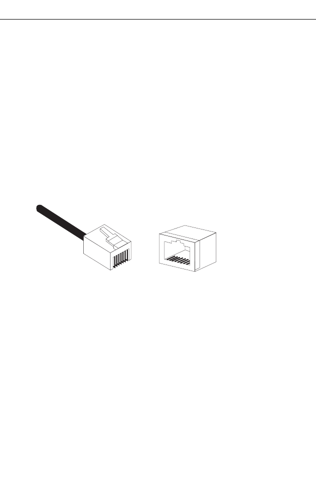
B-1
Appendix B: Cables and Pinouts
Twisted-Pair Cable Assignments
For 10/100BASE-TX connections, a twisted-pair cable must have two pairs of wires.
Each wire pair is identified by two different colors. For example, one wire might be
green and the other, green with white stripes. Also, an RJ-45 connector must be
attached to both ends of the cable.
Caution: Each wire pair must be attached to the RJ-45 connectors in a specific
orientation. (See “Straight-Through Wiring” on page B-2 and “Crossover
Wiring” on page B-3 for an explanation.)
Caution: DO NOT plug a phone jack connector into the RJ-45 port. Use only
twisted-pair cables with RJ-45 connectors that conform with FCC standards.
The following figure illustrates how the pins on the RJ-45 connector are numbered.
Be sure to hold the connectors in the same orientation when attaching the wires to
the pins.
10/100BASE-TX Pin Assignments
Use unshielded twisted-pair (UTP) or shielded twisted-pair (STP) cable for RJ-45
connections: 100-ohm Category 3 or better cable for 10 Mbps connections, or
100-ohm Category 5 or better cable for 100 Mbps connections. Also be sure
that the
length of any twisted-pair connection does not exceed 100 meters (328 feet).
The RJ-45 port on the access point is wired with MDI pinouts. This means that you
must use crossover cables for connections to PCs or servers, and straight-through
cable for connections to switches or hubs. However, when connecting to devices
that support automatic MDI/MDI-X pinout configuration, you can use either
straight-through or crossover cable.
1
88
1

Cables and Pinouts
B-2
B
Straight-Through Wiring
Because the 10/100 Mbps port on the access point uses an MDI pin configuration,
you must use “straight-through” cable for network connections to hubs or switches
that only have MDI-X ports. However, if the device to which you are connecting
supports auto-MDIX operation, you can use either “straight-through” or “crossover”
cable.
Table B-1. 10/100BASE-TX MDI Port Pinouts
Pin MDI Signal Name
1 Transmit Data plus (TD+)
2 Transmit Data minus (TD-)
3 Receive Data plus (RD+)
4 GND (Positive Vport)
5 GND (Positive Vport)
6 Receive Data minus (RD-)
7 -48V feeding power (Negative- Vport)
8 -48V feeding power (Negative- Vport)
Note: The “+” and “-” signs represent the polarity of the wires that
make up each wire pair.
White/Orange Stripe
Orange
White/Green Stripe
Green
1
2
3
4
5
6
7
8
1
2
3
4
5
6
7
8
EIA/TIA 568B RJ-45 Wiring Standard
10/100BASE-TX Straight-through Cable
End A End B
Blue
White/Blue Stripe
Brown
White/Brown Stripe

Console Port Pin Assignments
B-3
B
Crossover Wiring
Because the 10/100 Mbps port on the access point uses an MDI pin configuration,
you must use “crossover” cable for network connections to PCs, servers or other
end nodes that only have MDI ports. However, if the device to which you are
connecting supports auto-MDIX operation, you can use either “straight-through” or
“crossover” cable.
Console Port Pin Assignments
The DB-9 console port on the front panel of the access point is used to connect to
the access point for out-of-band console configuration. The command-line
configuration program can be accessed from a terminal, or a PC running a terminal
emulation program. The pin assignments and cable wiring used to connect to the
console port are provided in the following table.
White/Orange Stripe
Orange
White/Green Stripe
1
2
3
4
5
6
7
8
1
2
3
4
5
6
7
8
EIA
/
TIA 568B RJ-45 Wiring
S
tandard
10/100BASE-TX Crossover Cable
End A End B
Green
Blue
White/Blue Stripe
Brown
White/Brown Stripe
15
69

Cables and Pinouts
B-4
B
Wiring Map for Serial Cable
Table B-2. Wiring Map for Serial Cable
DB9 Male (AP Console) DB9 Male (PC DTE)
Pin Function Pin Function
1 GND (ground) 5 GND (ground)
2 Unused 4Unused
3 RXD (receive data) 3 TXD (transmit data)
4 TXD (transmit data) 2 RXD (receive data)
5 Unused 1 Unused
6 Unused 9 Unused
7 RTS (request to send) 8 CTS (clear to send)
8 CTS (clear or send) 7 RTS (request to send)
9 Unused 6 Unused
Note: The left hand column pin assignments are for the male DB-9 connector on the access point. Pin 4
(TXD or “transmit data”) must emerge on the management console’s end of the connection as RXD
(“receive data”). Pin 8 (CTS or “clear to send”) must emerge on the management console’s end of
the connection as RTS (“request to send”)

C-1
Appendix C: Specifications
General Specifications
Maximum Channels
802.11a:
US & Canada: 13 (normal mode), 5 (turbo mode)
Japan: 4 (normal mode), 1 (turbo mode)
ETSI: 11 channels (normal mode), 4 (turbo mode)
Taiwan: 8 (normal mode), 3 (turbo mode)
802.11b/g:
FCC/IC: 1-11
ETSI: 1-13
France: 10-13
MKK: 1-14
Taiwan: 1-11
Maximum Clients
64 per VAP interface
Operating Range
See “Operating Range” on page C-6
Data Rate
802.11a:
Normal Mode: 6, 9, 12, 18, 24, 36, 48, 54 Mbps per channel
Turbo Mode: 12, 18, 24, 36, 48, 54, 96, 108 Mbps per channel
802.11g: 6, 9, 11, 12, 18, 24, 36, 48, 54 Mbps per channel
802.11b: 1, 2, 5.5, 11 Mbps per channel
Modulation Type
802.11a: BPSK, QPSK, 16-QAM, 64-QAM
802.11g: CCK, BPSK, QPSK, OFDM
802.11b: CCK, BPSK, QPSK
Network Configuration
Infrastructure

Specifications
C-2
C
Operating Frequency
802.11a:
5.15 ~ 5.25 GHz (lower band) US/Canada, Japan
5.25 ~ 5.35 GHz (middle band) US/Canada
5.725 ~ 5.825 GHz (upper band) US/Canada
5.50~ 5.70 GHz Europe
5.25 ~ 5.35 GHz (middle band) Taiwan
5.725 ~ 5.825 GHz (high band) Taiwan
802.11b:
2.4 ~ 2.4835 GHz (US, Canada, ETSI)
2.4 ~ 2.497 GHz (Japan)
2.400 ~ 2.4835 GHz (Taiwan)
AC Power Adapter
Input: 100-240 AC, 50-60 Hz
Output: 5.1 VDC, 3A
Power consumption: 13.2 watts
Unit Power Supply
DC Input: 5 VDC, 1.92 A maximum
PoE input: -48 VDC, 0.27 A maximum
Power consumption: 9.6 W maximum
PoE (DC)
Input voltage: 48 volts, 0.27A, 12.96 watts
Note: Power can also be provided to the access point through the Ethernet port based
on IEEE 802.3af Power over Ethernet (PoE) specifications. When both PoE is
provided and the adapter is plugged in, PoE will be turned off.
Physical Size
21.83 x 13.73 x 3.27 cm (8.60 x 5.40 x 1.29 in)
Weight
0.745 kg (1.642 lbs)
LED Indicators
PWR (Power), Link (Ethernet Link/Activity), 11a and 11g (Wireless Link/Activity)
Network Management
Web-browser, RS232 console, Telnet, SSH, SNMP
Temperature
Operating: 0 to 55 °C (32 to 122 °F)
Storage: 0 to 70 °C (32 to 158 °F)
Humidity
15% to 95% (non-condensing)

General Specifications
C-3
C
Compliances
FCC Class B (US)
ICES-003 (Canada)
RTTED 1999/5/EC
VCCI (Japan)
RCR STD-33A
Radio Signal Certification
FCC Part 15C 15.247, 15.207 (2.4 GHz)
FCC part 15E 15.407 (5 GHz)
RSS-210 (Canada)
EN 301.893, EN 300.328, EN 301.489-1, EN 301.489-17
MPT RCR std.33 (D33 1~13 Channel, T66 Channel 14)
Safety
CSA/NTRL (CSA 22.2 No. 60950 & UL60950)
EN60950 (TÜV/GS), IEC60950 (CB)
Standards
IEEE 802.3 10BASE-T, IEEE 802.3u 100BASE-TX,
IEEE 802.11a, b, g

Specifications
C-4
C
Sensitivity
IEEE 802.11a Sensitivity (GHz - dBm)
Modulation/Rates 5.15-5.250 5.25-5.350 5.50-5.700 5.725-5.825
BPSK (6 Mbps) -88 -88 -88 -88
BPSK (9 Mbps) -87 -87 -87 -87
QPSK (12 Mbps) -86 -86 -86 -86
QPSK (18 Mbps) -84 -84 -84 -84
16 QAM (24 Mbps) -82 -81 -81 -81
16 QAM (36 Mbps) -80 -79 -78 -78
64 QAM (48 Mbps) -73 -73 -73 -73
64QAM(54 Mbps) -70 -70 -69 -67
IEEE 802.11g
Data Rate Sensitivity (dBm)
6 Mbps -88
9 Mbps -87
12 Mbps -86
17 Mbps -85
24 Mbps -81
36 Mbps -77
48 Mbps -72
54 Mbps -70
IEEE 802.11b
Data Rate Sensitivity (dBm)
1 Mbps -93
2 Mbps -90
5.5 Mbps -90
11 Mbps -87

Transmit Power
C-5
C
Transmit Power
IEEE 802.11a Maximum Output Power (GHz - dBm)
Data Rate 5.15-5.250 5.25-5.350 5.50-5.700 5.725-5.825
6 Mbps 17 17 17 17
9 Mbps 17 17 17 17
12 Mbps 17 17 17 17
8 Mbps 17 17 17 17
24 Mbps 17 17 17 17
36 Mbps 17 17 17 17
48 Mbps 17 17 17 17
54 Mbps 12 17 17 16
IEEE 802.11g Maximum Output Power (GHz - dBm)
Data Rate 2.412 2.417~2.467 2.472
6 Mbps 20 20 18
9 Mbps 20 20 18
12 Mbps 20 20 18
18 Mbps 20 20 18
24 Mbps 20 20 18
36 Mbps 18 19 17
48 Mbps 17 16 15
54 Mbps 15 14 13
IEEE 802.11b Maximum Output Power (GHz - dBm)
Data Rate 2.412 2.417~2.467 2.472
1 Mbps 15 16 15
2 Mbps 15 16 15
5.5 Mbps 15 16 15
11 Mbps 15 16 15

Specifications
C-6
C
Operating Range
Important Notice
Maximum distances posted below are actual tested distance thresholds. However,
there are many variables such as barrier
composition and construction and local
environmental interference
that may impact your actual distances and cause you to
experience
distance thresholds far lower than those posted below.
Notes: 1. Outdoor Environment: A line-of-sight environment with no interference or
obstruction between the access point and clients.
2. Indoor Environment: A typical office or home environment with floor to ceiling
obstructions between the access point and clients.
Table C-1 802.11a Wireless Distance Table
Speed and Distance Ranges
Environment 108
Mbps 72
Mbps 54
Mbps 48
Mbps 36
Mbps 24
Mbps 18
Mbps 12
Mbps 9
Mbps 6
Mbps
Outdoors130 m
99 ft
40 m
131 ft
85 m
279 ft
250 m
820 ft
310 m
1016 ft
400 m
1311 ft
445 m
1459 ft
455 m
1492 ft
465 m
1525 ft
510 m
1672 ft
Indoors215 m
49.5 ft 20 m
66 ft 25 m
82 ft 35 m
115 ft 40 m
131 ft
45 m
148 ft
50 m
164 ft
55 m
180 ft
66 m
216 ft
70 m
230 ft
Table C-2 802.11g Wireless Distance Table
Speed and Distance Ranges
Environment 54
Mbps 48
Mbps 36
Mbps 24
Mbps 18
Mbps 12
Mbps 11
Mbps 9
Mbps 6
Mbps 5
Mbps 2
Mbps 1
Mbps
Outdoors182 m
269 ft 100 m
328 ft 300 m
984 ft 330 m
1082 ft 350 m
1148 ft 450 m
1475 ft 470 m
1541 ft 485 m
1590 ft 495 m
1623 ft 510 m
1672 ft 520 m
1705 ft 525 m
1722 ft
Indoors220 m
66 ft 25 m
82 ft 35 m
115 ft 43 m
141 ft 50 m
164 ft 57 m
187 ft 66 m
216 ft 71 m
233 ft 80 m
262 ft 85 m
279 ft 90 m
295 ft 93 m
305 ft
Table C-3 802.11b Wireless Distance Table
Speed and Distance Ranges
Environment 11 Mbps 5.5 Mbps 2 Mbps 1 Mbps
Outdoors1300 m
984 ft 465 m
1525 ft 500 m
1639 ft 515 m
1689 ft
Indoors260 m
197 ft 70 m
230 ft 83 m
272 ft 85 m
279 ft

Glossary-1
Glossary
10BASE-T
IEEE 802.3 specification for 10 Mbps Ethernet over two pairs of Category 3 or better UTP
cable.
100BASE-TX
IEEE 802.3u specification for 100 Mbps Fast Ethernet over two pairs of Category 5 or
better UTP cable.
Access Point
An internetworking device that seamlessly connects wired and wireless networks. Access
points attached to a wired network, support the creation of multiple radio cells that enable
roaming throughout a facility.
Ad Hoc
A group of computers connected as an independent wireless network, without an access
point.
Advanced Encryption Standard (AES)
An encryption algorithm that implements symmetric key cryptography. AES provides very
strong encryption using a completely different ciphering algorithm to TKIP and WEP.
Authentication
The process to verify the identity of a client requesting network access. IEEE 802.11
specifies two forms of authentication: open system and shared key.
Backbone
The core infrastructure of a network. The portion of the network that transports
information from one central location to another central location where it is unloaded onto
a local system.
Basic Service Set (BSS)
A set of 802.11-compliant stations and an access point that operate as a fully-connected
wireless network.
Beacon
A signal periodically transmitted from the access point that is used to identify the service
set, and to maintain contact with wireless clients.

Glossary-2
Glossary
Broadcast Key
Broadcast keys are sent to stations using 802.1X dynamic keying. Dynamic broadcast
key rotation is often used to allow the access point to generate a random group key and
periodically update all key-management capable wireless clients.
CSMA/CA
Carrier Sense Multiple Access with Collision Avoidance.
Dynamic Host Configuration Protocol (DHCP)
Provides a framework for passing configuration information to hosts on a TCP/IP
network. DHCP is based on the Bootstrap Protocol (BOOTP), adding the capability of
automatic allocation of reusable network addresses and additional configuration options.
Encryption
Data passing between the access point and clients can use encryption to protect from
interception and evesdropping.
Extended Service Set (ESS)
More than one wireless cell can be configured with the same Service Set Identifier to
allow mobile users can roam between different cells with the Extended Service Set.
Extensible Authentication Protocol (EAP)
An authentication protocol used to authenticate network clients. EAP is combined with
IEEE 802.1X port authentication and a RADIUS authentication server to provide “mutual
authentication” between a client, the access point, and the a RADIUS server
Ethernet
A popular local area data communications network, which accepts transmission from
computers and terminals.
File Transfer Protocol (FTP)
A TCP/IP protocol used for file transfer.
Hypertext Transfer Protocol (HTTP)
HTTP is a standard used to transmit and receive all data over the World Wide Web.
IEEE 802.11a
A wireless standard that supports high-speed communications in the 5 GHz band using
Orthogonal Frequency Division Multiplexing (OFDM). The standard supports data rates
of 6, 12, 24, and 54 Mbps.

Glossary-3
Glossary
IEEE 802.11b
A wireless standard that supports wireless communications in the 2.4 GHz band using
Direct Sequence Spread Spectrum (DSSS). The standard provides for data rates of 1, 2,
5.5, and 11 Mbps.
IEEE 802.11g
A wireless standard that supports wireless communications in the 2.4 GHz band using
using Orthogonal Frequency Division Multiplexing (OFDM). The standard provides for
data rates of 6, 9, 11, 12, 18, 24, 36, 48, 54 Mbps. IEEE 802.11g is also backward
compatible with IEEE 802.11b.
IEEE 802.1X
Port Authentication controls access to the switch ports by requiring users to first enter a
user ID and password for authentication.
Infrastructure
An integrated wireless and wired LAN is called an infrastructure configuration.
Inter Access Point Protocol (IAPP)
A protocol that specifies the wireless signaling required to ensure the successful
handover of wireless clients roaming between different 802.11f-compliant access points.
Local Area Network (LAN)
A group of interconnected computer and support devices.
MAC Address
The physical layer address used to uniquely identify network nodes.
Network Time Protocol (NTP)
NTP provides the mechanisms to synchronize time across the network. The time servers
operate in a hierarchical-master-slave configuration in order to synchronize local clocks
within the subnet and to national time standards via wire or radio.
Open System
A security option which broadcasts a beacon signal including the access point’s
configured SSID. Wireless clients can read the SSID from the beacon, and automatically
reset their SSID to allow immediate connection to the nearest access point.
Orthogonal Frequency Division Multiplexing (ODFM)
OFDM/ allows multiple users to transmit in an allocated band by dividing the bandwidth
into many narrow bandwidth carriers.

Glossary-4
Glossary
Power over Ethernet (PoE)
A specification for providing both power and data to low-power network devices using a
single Category 5 Ethernet cable. PoE provides greater flexibility in the locating of access
point’s and network devices, and significantly decreased installation costs.
RADIUS
A logon authentication protocol that uses software running on a central server to control
access to the network.
Roaming
A wireless LAN mobile user moves around an ESS and maintains a continuous
connection to the infrastructure network.
RTS Threshold
Transmitters contending for the medium may not be aware of each other. RTS/CTS
mechanism can solve this “Hidden Node Problem.” If the packet size is smaller than the
preset RTS Threshold size, the RTS/CTS mechanism will NOT be enabled.
Service Set Identifier (SSID)
An identifier that is attached to packets sent over the wireless LAN and functions as a
password for joining a particular radio cell; i.e., Basic Service Set (BSS).
Session Key
Session keys are unique to each client, and are used to authenticate a client connection,
and correlate traffic passing between a specific client and the access point.
Shared Key
A shared key can be used to authenticate each client attached to a wireless network.
Shared Key authentication must be used along with the 802.11 Wireless Equivalent
Privacy algorithm.
Simple Network Management Protocol (SNMP)
The application protocol in the Internet suite of protocols which offers network
management services.
Simple Network Time Protocol (SNTP)
SNTP allows a device to set its internal clock based on periodic updates from a Network
Time Protocol (NTP) server. Updates can be requested from a specific NTP server, or
can be received via broadcasts sent by NTP servers.

Glossary-5
Glossary
Temporal Key Integrity Protocol (TKIP)
A data encryption method designed as a replacement for WEP. TKIP avoids the
problems of WEP static keys by dynamically changing data encryption keys.
Trivial File Transfer Protocol (TFTP)
A TCP/IP protocol commonly used for software downloads.
Virtual Access Point (VAP)
Virtual AP technology multiplies the number of Access Points present within the RF
footprint of a single physical access device. With Virtual AP technology, WLAN users
within the device’s footprint can associate with what appears to be different access points
and their associated network services. All the services are delivered using a single radio
channel, enabling Virtual AP technology to optimize the use of limited WLAN radio
spectrum.
Virtual LAN (VLAN)
A Virtual LAN is a collection of network nodes that share the same collision domain
regardless of their physical location or connection point in the network. A VLAN serves
as a logical workgroup with no physical barriers, and allows users to share information
and resources as though located on the same LAN.
Wi-Fi Protected Access
WPA employs 802.1X as its basic framework for user authentication and dynamic key
management to provide an enhanced security solution for 802.11 wireless networks.
Wired Equivalent Privacy (WEP)
WEP is based on the use of security keys and the popular RC4 encryption algorithm.
Wireless devices without a valid WEP key will be excluded from network traffic.
WPA Pre-shared Key (PSK)
PSK can be used for small office networks that may not have the resources to configure
and maintain a RADIUS server, WPA provides a simple operating mode that uses just a
pre-shared password for network access.

Glossary-6
Glossary

Index-1
Numerics
802.11g 7-94
A
AES 6-76
antennas, positioning 2-2
authentication 6-12, 7-116
cipher suite 6-79, 7-117
closed system 7-106
configuring 6-12, 7-116
MAC address 6-13, 7-70, 7-71
type 6-66, 7-106
web redirect 6-14, 7-20
B
Basic Service Set See BSS
beacon
interval 6-56, 7-101
rate 6-56, 7-101
BOOTP 7-88, 7-89
BPDU 6-24
BSS 4-3
C
cable
assignments B-1
crossover B-3
straight-through B-2
CCK 1-1
channel 7-96
channels, maximum C-1
Clear To Send See CTS
CLI 7-1
command modes 7-4
clients, maximum C-1
closed system 6-50, 7-106
command line interface See CLI
community name, configuring 7-41
community string 6-39, 7-41
configuration settings, saving or
restoring 6-31, 7-56
configuration, initial setup 5-1
console port 1-4
connecting 2-2
pin assignments B-3
required settings 5-1
country code
configuring 5-3, 7-12
crossover cable B-3
CSMA/CA 1-1
CTS 6-57, 7-103
D
data rate
maximum distances C-6
data rate, options C-1
default settings 1-6
device status, displaying 6-84, 7-23
DHCP 6-5, 7-88, 7-89
distances, maximum C-6
DNS 6-6, 7-88
Domain Name Server See DNS
downloading software 6-29, 7-56
DSSS 1-1
DTIM 6-56, 7-101
Dynamic Host Configuration Protocol
See DHCP
E
EAP 6-75
encryption 6-66, 6-71, 6-75
Ethernet
cable 2-2
port 1-4
event logs 6-90, 7-32
Extensible Authentication Protocol See
EAP
F
factory defaults
restoring 6-31, 7-10
Index

Index
Index-2
filter 6-17, 7-70
address 6-12, 7-70
between wireless clients 6-17, 7-73
local bridge 6-17, 7-73
local or remote 6-12, 7-72
management access 6-17, 7-74
protocol types 6-18, 7-74
VLANs 6-50, 7-130
firmware
displaying version 6-31, 7-24
upgrading 6-29, 6-31, 7-56
fragmentation 7-102
G
gateway address 5-2, 6-6, 7-1, 7-88
H
hardware version, displaying 7-24
HTTP, secure server 7-19
HTTPS 7-19
I
IAPP 7-129
IEEE 802.11a 1-1, 6-48, 7-94
configuring interface 6-49, 7-94
maximum data rate 7-96
radio channel 7-96
IEEE 802.11b 6-48
IEEE 802.11f 7-129
IEEE 802.11g 6-48
configuring interface 6-63, 7-94
maximum data rate 7-96
radio channel 6-65, 7-96
IEEE 802.1x 6-75, 7-65, 7-70
configuring 6-81, 7-65
infrastructure
wireless bridge 4-5
wireless repeater 4-6
initial setup 5-1
installation
hardware 2-1, 3-1
location considerations 3-1
mounting 2-1
IP address
BOOTP/DHCP 7-88, 7-89
configuring 5-2, 6-5, 7-88, 7-89
L
LED indicators 1-3
location for the access point,
considerations 3-1
lock, Kensington 2-1
log
messages 6-34, 6-90, 7-29
server 6-33, 7-29
login
CLI 7-1
web 5-3
logon authentication
RADIUS client 6-14, 7-59
M
MAC address, authentication 6-13,
7-70, 7-71
maximum associated clients 6-55
maximum data rate 7-96
802.11a interface 7-96
802.11g interface 7-96
maximum distances C-6
MDI, RJ-45 pin configuration 1-4
mounting the access point 2-1
N
network topologies
infrastructure 4-3
infrastructure for roaming 4-4
O
OFDM 1-1
open system 6-66, 7-106
operating frequency C-2
P
package checklist 1-2
password
configuring 6-28, 7-15
management 6-28, 7-15

Index
Index-3
pin assignments
console port B-3
DB-9 port B-3
PoE 1-5
specifications C-2
port priority
STA 7-85
power connection 2-1
Power over Ethernet See PoE
power supply, specifications C-2
PSK 6-76
R
radio channel
802.11a interface 7-96
802.11g interface 6-65, 7-96
RADIUS 6-7, 6-75, 7-59
RADIUS, logon authentication 6-14,
7-59
Remote Authentication Dial-in User
Service See RADIUS
Request to Send See RTS
reset 6-31, 7-10
reset button 1-5, 6-31
resetting the access point 6-31, 7-10
restarting the system 6-31, 7-10
RJ-45 port
configuring duplex mode 7-90
configuring speed 7-90
RTS
threshold 6-57, 7-103
S
Secure Socket Layer See SSL
security, options 6-66
session key 6-81, 6-82, 7-67
shared key 6-72, 7-119
Simple Network Time Protocol See
SNTP
SNMP 6-38, 7-40
community name 7-41
community string 7-41
enabling traps 6-39, 7-42
trap destination 6-39, 7-43
trap manager 6-39, 7-43
SNTP 6-35, 7-34
enabling client 6-35, 7-34
server 6-35, 7-34
software
displaying version 6-29, 6-84, 7-24
downloading 6-31, 7-56
specifications C-1
SSH
server Status 6-11
SSID 6-70, 7-105
SSL 7-19
STA
interface settings 7-85–??
path cost 7-85
port priority 7-85
startup files, setting 7-55
station status 6-87, 7-110
status
displaying device status 6-84, 7-23
displaying station status 6-87, 7-110
straight-through cable B-2
system clock, setting 6-35, 7-35
system log
enabling 6-33, 7-29
server 6-33, 7-29
system software, downloading from
server 6-29, 7-56
T
Telnet
for managenet access 7-1
Temporal Key Integrity Protocol See
TKIP
time zone 6-36, 7-36
TKIP 6-75
transmit power, configuring 6-55, 7-97
trap destination 6-39, 7-43
trap manager 6-39, 7-43
troubleshooting A-1
U
upgrading software 6-29, 7-56
user name, manager 6-28, 7-15
user password 6-28, 7-15

Model Number: WA6102X-2AG-17
Pub. Number: 150000030500E, E012006-R03