Accton Technology 3CRWE554G72 OfficeConnect Wireless 11g Cable/DSL Gateway User Manual Part 1 Revised
Accton Technology Corp OfficeConnect Wireless 11g Cable/DSL Gateway Users Manual Part 1 Revised
Contents
- 1. DoC
- 2. Users Manual Part 1 Revised
- 3. Users Manual Part 2 Revised
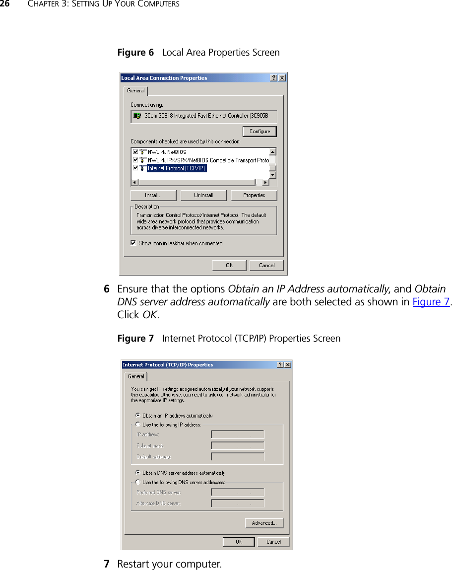
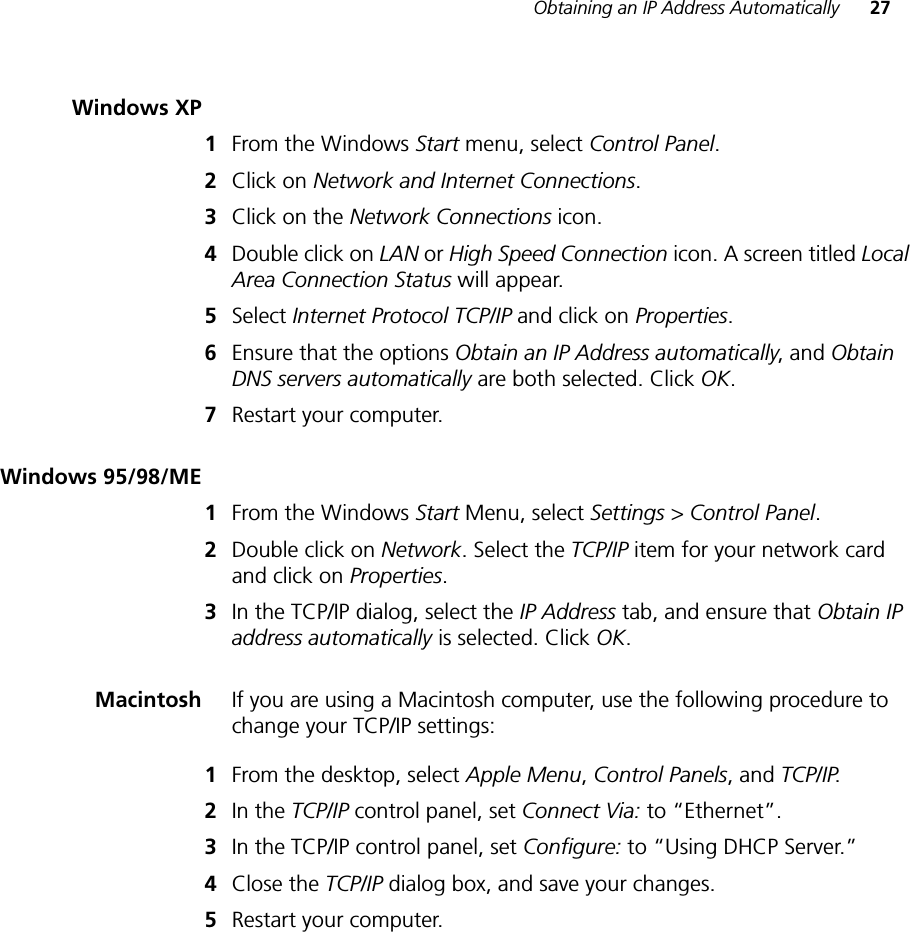
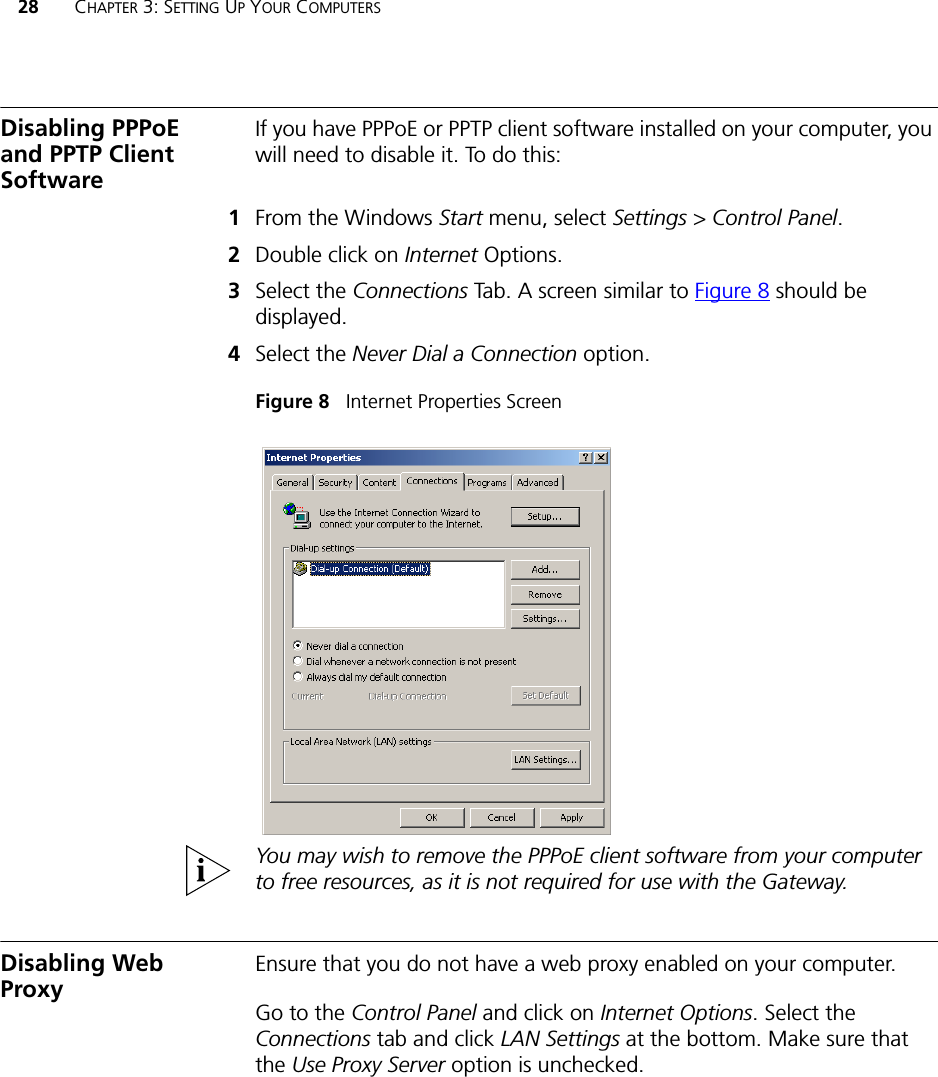
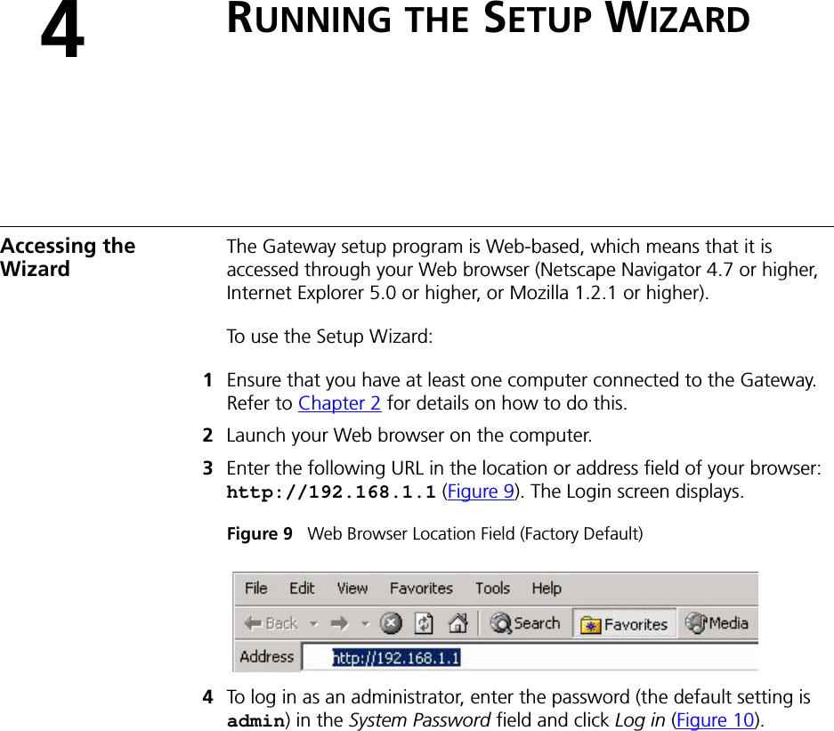
Users Manual Part 1 Revised